Embed Size (px)
Citation preview

TI418F/24/ae
Technical Information
Solicap M FTI55, FTI56
Level Limit Switch
Universal Capacitive Limit Switch for Bulk Solids
Application
The compact transmitter is used for level limit detection
in bulk solids and can be operated in minimum or
maximum failsafe mode.
Due to its robust construction, it can also be used to
provide accurate measurements in applications with very
high tensile loads up to 13,500 lb/f (60 kN) for cable
version, or lateral loads up to 220 lbf ft (300 Nm) for rod
version.
In combination with Fieldgate (for remote interrogation
of measured values using internet technology),
Solicap M represents an ideal solution for material
provisioning and logistical optimization (inventory
control).
Your benefits
• Extremely robust design for harsh process conditions
• Easy and fast commissioning, calibration is performed
at the press of a button
• All major agency approvals
• Two-stage overvoltage protection against static
discharges from the silo
• Active buildup compensation for bulk solids with
caking tendency (under development)
• Increased safety due to permanent automatic
monitoring of electronics
• Reduction in storage costs thanks to easy-to-shorten
rod model (for partial insulation) and cable model
(for partial and full insulation)
• Two-point control (e.g. for controlling a handling
device)

Level limit detection with Solicap M FTI55, FTI56
2 Endress+Hauser
Table of contents
Function and system design. . . . . . . . . . . . . . . . . . . . . 4
Measuring principle . . . . . . . . . . . . . . . . . . . . . . . . . . . . . . . . . . . 4
Application examples . . . . . . . . . . . . . . . . . . . . . . . . . . . . . . . . . . 4
Electronic versions . . . . . . . . . . . . . . . . . . . . . . . . . . . . . . . . . . . . 4
Measuring system . . . . . . . . . . . . . . . . . . . . . . . . . . . . . . . . . . . . . 5
System integration via Fieldgate . . . . . . . . . . . . . . . . . . . . . . . . . . 7
Operating conditions: Installation . . . . . . . . . . . . . . . . 8
Installation instructions . . . . . . . . . . . . . . . . . . . . . . . . . . . . . . . . . 8
General notes . . . . . . . . . . . . . . . . . . . . . . . . . . . . . . . . . . . . . . . . 8
Preparing to install FTI55 . . . . . . . . . . . . . . . . . . . . . . . . . . . . . . 9
Preparing to install FTI56 . . . . . . . . . . . . . . . . . . . . . . . . . . . . . 11
With remote housing . . . . . . . . . . . . . . . . . . . . . . . . . . . . . . . . . 14
Operating conditions: Environment. . . . . . . . . . . . . . 16
Ambient temperature range . . . . . . . . . . . . . . . . . . . . . . . . . . . . 16
Storage temperature . . . . . . . . . . . . . . . . . . . . . . . . . . . . . . . . . . 16
Climate class . . . . . . . . . . . . . . . . . . . . . . . . . . . . . . . . . . . . . . . 16
Degree of protection . . . . . . . . . . . . . . . . . . . . . . . . . . . . . . . . . . 16
Vibration resistance . . . . . . . . . . . . . . . . . . . . . . . . . . . . . . . . . . 16
Cleaning . . . . . . . . . . . . . . . . . . . . . . . . . . . . . . . . . . . . . . . . . . 16
Electromagnetic compatibility (EMC) . . . . . . . . . . . . . . . . . . . . . 16
Shock resistance . . . . . . . . . . . . . . . . . . . . . . . . . . . . . . . . . . . . 16
Operating conditions: Process . . . . . . . . . . . . . . . . . . 17
Process temperature range . . . . . . . . . . . . . . . . . . . . . . . . . . . . . 17
Process pressure and temperature derating . . . . . . . . . . . . . . . . . 19
Types of process medium. . . . . . . . . . . . . . . . . . . . . . . . . . . . . . 19
Mechanical construction . . . . . . . . . . . . . . . . . . . . . . 20
Overview . . . . . . . . . . . . . . . . . . . . . . . . . . . . . . . . . . . . . . . . . . 20
Technical data (probe) . . . . . . . . . . . . . . . . . . . . . . . . . . . . . . . . 25
Material . . . . . . . . . . . . . . . . . . . . . . . . . . . . . . . . . . . . . . . . . . . 25
Weight . . . . . . . . . . . . . . . . . . . . . . . . . . . . . . . . . . . . . . . . . . . . 25
Input . . . . . . . . . . . . . . . . . . . . . . . . . . . . . . . . . . . . . 26
Measured variable . . . . . . . . . . . . . . . . . . . . . . . . . . . . . . . . . . . 26
Measuring range (valid for all FEI5x) . . . . . . . . . . . . . . . . . . . . . 26
Input signal . . . . . . . . . . . . . . . . . . . . . . . . . . . . . . . . . . . . . . . . 26
Measuring conditions . . . . . . . . . . . . . . . . . . . . . . . . . . . . . . . . . 26
Output . . . . . . . . . . . . . . . . . . . . . . . . . . . . . . . . . . . . 27
Galvanic isolation . . . . . . . . . . . . . . . . . . . . . . . . . . . . . . . . . . . . 27
Switch behavior . . . . . . . . . . . . . . . . . . . . . . . . . . . . . . . . . . . . . 27
Switch-on behavior . . . . . . . . . . . . . . . . . . . . . . . . . . . . . . . . . . 27
Failsafe mode . . . . . . . . . . . . . . . . . . . . . . . . . . . . . . . . . . . . . . . 27
Switching delay . . . . . . . . . . . . . . . . . . . . . . . . . . . . . . . . . . . . . 27
FEI52 electronic insert (DC PNP) . . . . . . . . . . . . . . . 28
Power supply . . . . . . . . . . . . . . . . . . . . . . . . . . . . . . . . . . . . . . . 28
Electrical connection . . . . . . . . . . . . . . . . . . . . . . . . . . . . . . . . . 28
Output signal . . . . . . . . . . . . . . . . . . . . . . . . . . . . . . . . . . . . . . . 28
Signal on alarm . . . . . . . . . . . . . . . . . . . . . . . . . . . . . . . . . . . . . 28
Connectable load . . . . . . . . . . . . . . . . . . . . . . . . . . . . . . . . . . . . 28
Electronic insert FEI53 (3-wire) . . . . . . . . . . . . . . . . 29
Power supply . . . . . . . . . . . . . . . . . . . . . . . . . . . . . . . . . . . . . . . 29
Electrical connection . . . . . . . . . . . . . . . . . . . . . . . . . . . . . . . . . 29
Output signal . . . . . . . . . . . . . . . . . . . . . . . . . . . . . . . . . . . . . . . 29
Signal on alarm . . . . . . . . . . . . . . . . . . . . . . . . . . . . . . . . . . . . . 29
Connectable load . . . . . . . . . . . . . . . . . . . . . . . . . . . . . . . . . . . . 29
FEI54 electronic insert (AC/DC with relay output) . . 30
Power supply . . . . . . . . . . . . . . . . . . . . . . . . . . . . . . . . . . . . . . . 30
Electrical connection . . . . . . . . . . . . . . . . . . . . . . . . . . . . . . . . . 30
Output signal . . . . . . . . . . . . . . . . . . . . . . . . . . . . . . . . . . . . . . . 30
Signal on alarm . . . . . . . . . . . . . . . . . . . . . . . . . . . . . . . . . . . . . 30
Connectable load . . . . . . . . . . . . . . . . . . . . . . . . . . . . . . . . . . . . 30
FEI55 electronic insert (8/16 mA) . . . . . . . . . . . . . . 31
Power supply . . . . . . . . . . . . . . . . . . . . . . . . . . . . . . . . . . . . . . . 31
Electrical connection . . . . . . . . . . . . . . . . . . . . . . . . . . . . . . . . . 31
Output signal . . . . . . . . . . . . . . . . . . . . . . . . . . . . . . . . . . . . . . . 31
Signal on alarm . . . . . . . . . . . . . . . . . . . . . . . . . . . . . . . . . . . . . 31
Connectable load . . . . . . . . . . . . . . . . . . . . . . . . . . . . . . . . . . . . 31
FEI57S electronic insert (PFM) . . . . . . . . . . . . . . . . . 32
Power supply . . . . . . . . . . . . . . . . . . . . . . . . . . . . . . . . . . . . . . . 32
Electrical connection . . . . . . . . . . . . . . . . . . . . . . . . . . . . . . . . . 32
Output signal . . . . . . . . . . . . . . . . . . . . . . . . . . . . . . . . . . . . . . . 32
Signal on alarm . . . . . . . . . . . . . . . . . . . . . . . . . . . . . . . . . . . . . 32
Connectable load . . . . . . . . . . . . . . . . . . . . . . . . . . . . . . . . . . . . 32
Power supply . . . . . . . . . . . . . . . . . . . . . . . . . . . . . . . 33
Electrical connection . . . . . . . . . . . . . . . . . . . . . . . . . . . . . . . . . 33
Cable entry . . . . . . . . . . . . . . . . . . . . . . . . . . . . . . . . . . . . . . . . 33
Performance characteristics. . . . . . . . . . . . . . . . . . . . 33
Reference operating . . . . . . . . . . . . . . . . . . . . . . . . . . . . . . . . . 33
Switchpoint deviation . . . . . . . . . . . . . . . . . . . . . . . . . . . . . . . . 33
Influence of ambient temperature . . . . . . . . . . . . . . . . . . . . . . . . 33
Human interface . . . . . . . . . . . . . . . . . . . . . . . . . . . . 34
Electronic inserts . . . . . . . . . . . . . . . . . . . . . . . . . . . . . . . . . . . . 34
Certificates and approvals . . . . . . . . . . . . . . . . . . . . . 35
CE approval . . . . . . . . . . . . . . . . . . . . . . . . . . . . . . . . . . . . . . . . 35
Hazardous area approvals . . . . . . . . . . . . . . . . . . . . . . . . . . . . . . 35
Other standards and guidelines . . . . . . . . . . . . . . . . . . . . . . . . . . 35
Ordering information. . . . . . . . . . . . . . . . . . . . . . . . . 35
Solicap M FTI55 . . . . . . . . . . . . . . . . . . . . . . . . . . . . . . . . . . . . 35
Solicap M FTI56 . . . . . . . . . . . . . . . . . . . . . . . . . . . . . . . . . . . . 37
Accessories . . . . . . . . . . . . . . . . . . . . . . . . . . . . . . . . 38
Weather protection cover . . . . . . . . . . . . . . . . . . . . . . . . . . . . . . 38
Overvoltage protection HAW569 for FEI55 and FEI57S . . . . . . . 38
Spare parts . . . . . . . . . . . . . . . . . . . . . . . . . . . . . . . . . . . . . . . . . 39

3 Endress+Hauser
Level limit detection with Solicap M FTI55, FTI56
Documentation . . . . . . . . . . . . . . . . . . . . . . . . . . . . . 39
Technical Information . . . . . . . . . . . . . . . . . . . . . . . . . . . . . . . . 39
Operating Instructions . . . . . . . . . . . . . . . . . . . . . . . . . . . . . . . . 39
Safety information (ATEX) . . . . . . . . . . . . . . . . . . . . . . . . . . . . . 39
Patents . . . . . . . . . . . . . . . . . . . . . . . . . . . . . . . . . . . . . . . . . . . 39

Level limit detection with Solicap M FTI55, FTI56
4 Endress+Hauser
Function and system design
Measuring principle The principle of capacitive level limit detection is based on the change in capacitance of a capacitor as a result
of the probe being covered by bulk solids. The probe and container wall (conductive material) form an electric
capacitor. When the probe is in air (1), a certain low initial capacitance is measured. If the container is being
filled, the capacitance of the capacitor increases as more of the probe is covered (2), (3).
The limit switch switches when the capacitance CS specified during calibration is reached.
In addition, a probe with inactive length ensures that the effects of medium buildup or condensate near the
process connection are avoided. A probe with active buildup compensation compensates for the effects of
buildup on the probe in the area of the process connection.
TI418F01
R: Conductivity of bulk solidsC: Capacity of bulk solidsCA: Initial capacitance (probe not covered)CS: Switching capacitanceΔC: Change in capacitance
Function
The electronic insert selected for the probe determines the change in capacitance depending on how much of
the probe is covered. This ensures accurate switching at the switchpoint (level) calibrated for this purpose.
Application examples Sand, glass aggregate, gravel, moulding sand, lime, ore (crushed), plaster, aluminium shavings, cement, grain,
pumice, flour, dolomite, sugar beet, kaolin, fodder and similar bulk solids.
In general:
Bulk solids with a relative dielectric constant εr ≥ 2.5.
Electronic versions FEI52
3-wire direct current version:
• Switch the load via the transistor (PNP) and separate supply voltage connection.
• Level limit adjustment directly at the level limit probe.
FEI53
3-wire direct current version with 3 to 12 V signal output:
• For separate switching unit, Nivotester FTC325 3–WIRE.
• Level limit adjustment directly at the switching unit.
FEI54
Universal current version with relay output:
• Switch the loads via 2 floating changeover contacts (DPDT).
• Level limit adjustment directly at the level limit probe.
FEI55
Signal transmission 8/16 mA on two-wire cabling:
• For separate switching unit (e.g. RN221N, RNS221, RMA421, RMA422).
• Level limit adjustment directly at the level limit probe.
CA
R
CCS
1.
CA
�C
2. 3.
Level limit detection with Solicap M FTI55, FTI56
Endress+Hauser 5
FEI57S
PFM signal transmission (current pulses are superimposed on the supply current):
• For separate switching unit with PFM signal transmission e.g. FTC325 PFM, FTC625 PFM and FTC470Z,
FTC471Z
• Self-test from the switching unit without changing levels.
• Level limit adjustment directly at the switching unit.
! Note!
For additional information see Page 28.
Measuring system The make-up of the measuring system depends on the electronic insert selected.
Level limit switch
The complete measuring system consists of:
• The capacitive level limit probe, Solicap M FTI55 or FTI56
• An FEI52, FEI54 electronic insert
TI418Fen02
EX EXFEI52, FEI54
Hazardous area Non-hazardousarea
Ex dDust-Ex

Level limit detection with Solicap M FTI55, FTI56
6 Endress+Hauser
Two-point control (Δs function)
! Note!
Only in conjunction with nonconductive bulk solids.
TI418Fen03
The level limit switch can also be used to control a screw conveyor, for example, where the on and off values
can be freely defined.
Level limit sensor
Solicap M FTI55, FTI56 with electronic versions FEI53, FEI57S for connecting to a separate switching unit.
The complete measuring system consists of:
• The capacitive level limit probe, Solicap M FTI55 or FTI56
• An FEI53, FEI57S electronic insert
• A transmitter power supply (e.g. FTC325, FTC625, FTC470Z, FTC471Z)
TI418Fen04
EX EXFEI52, FEI54
ON
OFF
ΔsConveyor screw
Ex dHazardousarea
Non-hazardousareaDust-Ex
EX EX
Hazardousarea
Non-hazardousarea
CH1
U~U~
FTC625T
FEI53 (non-Ex),FEI57S (Intrinsically safe)
Level limit detection with Solicap M FTI55, FTI56
Endress+Hauser 7
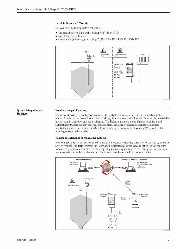
Level limit sensor 8/16 mA
The complete measuring system consists of:
• The capacitive level limit probe, Solicap M FTI55 or FTI56
• The FEI55 electronic insert
• A transmitter power supply unit (e.g. RN221N, RNS221, RMA421, RMA422)
TI418Fen05
System integration via
Fieldgate
Vendor managed inventory
The remote interrogation of tank or silo levels via Fieldgate enables suppliers of raw materials to gather
information about the current inventories of their regular customers at any time and, for example, to take this
into account in their own production planning. The Fieldgate monitors the configured level limits and
automatically triggers the next order as required. Here, the range of possibilities ranges from simple
requisitioning by e-mail through to fully automatic order processing by incorporating XML data into the
planning systems on both sides.
Remote maintenance of measuring systems
Fieldgate transmits the current measured values, and also alerts the standby personnel responsible by e-mail or
SMS as required. Fieldgate forwards the information transparently. In this way, all options of the operating
software in question are available remotely. By using remote diagnosis and remote configuration some local
service operations can be avoided and all others can at least be planned and prepared better.
TI418Fen06
EX
IntrinsicallySafe
Non-hazardousarea
EX
ENDRESS + HAUSERRMA422
On
Q-SET
+– E
FEI55
FXA191/195orDXR375
Transmitterpower supplyunit e.g.RMA422 orRN221N
PLC
RS485interface
AnalogEthernet
GSM
EX
CH1
U~U~
FTC625T
FEI57S (PFM)
Hazardous area
NivotesterFTC625
FieldgateFXA520
HTTP scriptweb browser…
via HART client:- ToF Tool - FieldToolPackage
- FieldCare. . .
Remote interrogation Remote configuration/diagnostics

Level limit detection with Solicap M FTI55, FTI56
8 Endress+Hauser
Operating conditions: Installation
! Note!
All dimensions are in inches (mm).
Installation instructions The Solicap M FTI55 (rod probe) can be installed from above and from the side.
The Solicap M FTI56 (cable probe) is installed vertically from above.
! Note!
• The probe may not come into contact with the container wall! Do not install probes in the area of the
filling stream!
• If the process connection of the probe is insulated from the metal container (e.g. using seal material),
the ground connection on the probe housing must be connected to the container using a short line.
General notes Filling the silo
The filling stream should not be
directed onto the probe.
Angle of material flow
Note the expected angle of the
material flow or of the outlet funnel
when determining the mounting
location or probe length.
Distance between probes
When installing several probes in a
silo, a minimum distance of 20"
(0.5 m) between the probes must be
observed.
Threaded coupling for mounting
When installing the Solicap M
FTI55, FTI56, the threaded coupling
should be as short as possible.
Condensation or product residue
may occur in a long threaded
coupling and interfere with the
correct operation of the probe.
Heat insulation
In the event of high temperatures in
the silo:
Insulate the external silo wall to
avoid exceeding the permitted
temperature of the Solicap M
housing.
Heat insulation also prevents
condensate from forming near the
threaded boss in the silo.
This reduces buildup and the risk of
error switching.
TI418Fen07
FTI55 FTI56
min. 20”(500)
min. 20”(500)
min. 20”(500)
FTI55
FTI55
Angle ofslope
Protectiveroof
Distance
Angle ofslope
approx.8”
(200)

Level limit detection with Solicap M FTI55, FTI56
Endress+Hauser 9
Preparing to install FTI55
Correct installation
a. For maximum level limit detection, a short threaded coupling is used.
b. For minimum detection, a protective roof protects against collapsing mounds or high strain
on the probe rod caused by the removal of material, if using the Solicap M FTI55.
c. In the event of light buildup on the silo wall, the threaded coupling is welded internally.
The probe tip points slightly downwards so that bulk solids slide off more easily.
Incorrect installation
d. The threaded coupling is too long. This may cause material to settle inside and result in error switching.
e. Horizontal mounting means a risk of error switching in the event of heavy buildup on the silo wall.
In this case, the Solicap M FTI55 (rod probe) with inactive length is recommended.
f. In areas where product buildup occurs, the device cannot detect if the silo is "empty".
In this case, the FTI56 (cable probe) should be installed from above.
Correct installation Incorrect installation
TI418Fen08
* Protective roof In a silo with metal walls
In this example, the steel plate forms the counter
electrode.
Heat insulation prevents condensation and therefore
buildup on the steel plate.
TI418Fen09
In a silo with concrete walls
d.a.
e.
c.
f.
b.
14.2”(360)
short
approx.
approx.8” (200)
8” (200)
Sheet metal platewiththreaded socket
Heat insulation
min. ø12” (300)or 12” (300)

Level limit detection with Solicap M FTI55, FTI56
10 Endress+Hauser
Probe length
! Note!
• The lengths given are minimum lengths in addition to the distance between the sealing surface of the flange
or thread and the level limit required. For probe length tolerances see Page 23.
• To ensure problem-free operation, it is important that the difference in capacitance between the covered and
uncovered parts of the probe is at least 5 pF.
• If you do not know the dielectric constant of the material, contact Endress+Hauser.
When installing in a silo made of plastic, a sheet
metal plate must be attached to the exterior of the
silo as a counter electrode.
This plate can be either square or round.
– Dimensions in the case of a thin silo wall with a
low dielectric constant:
approx. 20" (0.5 m) along each side or ø 20"
(0.5 m);
– Dimensions in the case of a thicker silo wall or
wall with a higher dielectric constant:
approx. 27" (0.7 m) along each side or ø 27"
(0.7 m).
TI418Fen10
In a silo with plastic walls
The required minimum distances can be
accomplished by staggering the installation.
TI418Fen11
For small differences in level
Product properties,
relative dielectric constant εr
TI418F12
* additional length to be covered
Electrically conductive 0.4" (10 mm)
Non-conductive
εr > 10 4" (100 mm)
εr > 5 to 10 8" (200 mm)
εr > 2 to 5 20" (500 mm)
Sheet metal plate
Ground connection
ElectricalHF field
e.g. 12”(300)
Min. 20”(500)
*

Level limit detection with Solicap M FTI55, FTI56
Endress+Hauser 11
Preparing to install FTI56
Correct installation
a. Solicap M FTI55, FTI56 with inactive length in the event of condensation and material buildup on the
silo roof.
b. At the correct distance from the silo wall, the material inlet and the material outlet.
Close to the wall, for reliable switching in the case of a low dielectric constant (not for pneumatic filling).
For pneumatic filling, the distance from the probe to the wall should not be too short, as the probe may
swing.
Incorrect installation
c. If too close to the material inlet, inflowing bulk solids may damage the sensor.
If close to the center of the material outflow, high tensile forces at this point may cause the probe to break
off or subject the silo roof to excessive strain.
d. The threaded coupling is too long. This may cause condensate and dust to settle inside which may result
in error switching.
e. If too close to the silo wall, the probe may swing slightly against the wall or come in contact with buildup.
This can result in error switching.
Correct installation Incorrect installation
TI418F13
In a silo with metal walls Distance D between the probe and the wall approx. 10 to 25 % of the silo diameter
a. b. c.
d.
e.
Dmin. 8”(0.2 m)

Level limit detection with Solicap M FTI55, FTI56
12 Endress+Hauser
Silo roof
Ensure that the silo roof is of a sufficiently stable construction.
High tensile forces may occur when material is being removed, particularly in the case of heavy and powdery
bulk solids which have a tendency to form buildup.
The cable tension calculation program from Endress+Hauser can be used to calculate the expected cable
tension values.
Coarse-grained bulk solids
In silos with extremely coarse-grained or extremely abrasive bulk solids, the use of a Solicap M FTI55 or FTI56
is recommended only for maximum detection.
Distance between probes
To avoid mutual interference, probes must be positioned at least 20" (0.5 m) apart. This applies also when using
several Solicap M devices in adjacent silos with nonconductive walls.
The threaded coupling, with a maximum length of 1"
(25 mm), should if possible protrude into the silo to
reduce the effects of condensation and buildup.
Heat insulation reduces condensation and therefore
buildup on the steel plate.
TI418Fen14
In a silo with concrete walls
Recommended:
Use the FTI56 with inactive length.
The inactive length prevents moisture and buildup
forming between the active part of the probe and the
silo roof.
TI418Fen15
Steel plate
Steel plate;connected to thereinforcing steel
Heat insulation
Recommended with condensation:
Active partof probe

Level limit detection with Solicap M FTI55, FTI56
Endress+Hauser 13
Range of sensor lengths
When installing in a silo made of plastic, a counter
electrode must be mounted on the silo exterior at the
same height as the tensioning weight.
The length of the edge of the counter electrode
should be approximately the same length as the
distance between the tensioning weight and the silo
wall.
TI418Fen16
In a silo with plastic walls
TI418Fen17
Electrically conductive
bulk solids
(e.g. coal)
Bulk solids with high
dielectric constant
(e.g. flour)
Bulk solids with low
dielectric constant
(e.g. dried grain)
* LB (covered length):
For nonconductive bulk solids with a low dielectric constant, the cable probe must be approx. 5 % (but no
less than 10" / 250 mm) longer than the distance between the tank roof and the required level limit.
Ground connection
ElectricalHF field
Surface areae.g. 10 ft (1 m²)²
Counter electrodee.g.sheet metal plate
Weight
Distancee.g. 3 ft(1 m)
L LL
LL
min. 10” *(250)min. 8”
(200)
B
B
Level

Level limit detection with Solicap M FTI55, FTI56
14 Endress+Hauser
With remote housing For information on how to order, see also "Ordering information", "Probe design" from Page 36.
TI418F18
Rod length L1 max. 13 ft (4 m); Cable length L1 max. 72 ft (22 m)
! Note!
• The maximum connection length between the probe and the remote housing is 20 ft / 6 m (L4). When
ordering a Solicap M with a remote housing, the desired length must be specified.
• If, however, the connecting cable is to be shortened or passed through a wall, it must be separated from the
process connection. See "Documentation", "Operating Instructions" on Page 39.
• The cable has a bending radius of r ≥ 4" (100 mm). This must be observed as a minimum.
Extension heights
EX
Hazardous Area(Zone 1) Hazardous
Area(Zone 2)
L4 20 ft (6 m)�
EX
L1
Housing side: wall mounting Housing side: pipe mounting Sensor side
TI418F19
Polyester housing F16 Stainless steel housing F15 Aluminum housing F17
B, inches (mm) 2.33 (76) 2.52 (64) 2.56 (65)
H1, inches (mm) 6.77 (172) 6.54 (166) 6.97 (177)
~2.40”(61)
~2.95”(75)
~1.61”(41)
~1.61”(41)
BB
H1 H1 H3
D
r 4”(100)
�
r 4”(100)
�
Level limit detection with Solicap M FTI55, FTI56
Endress+Hauser 15
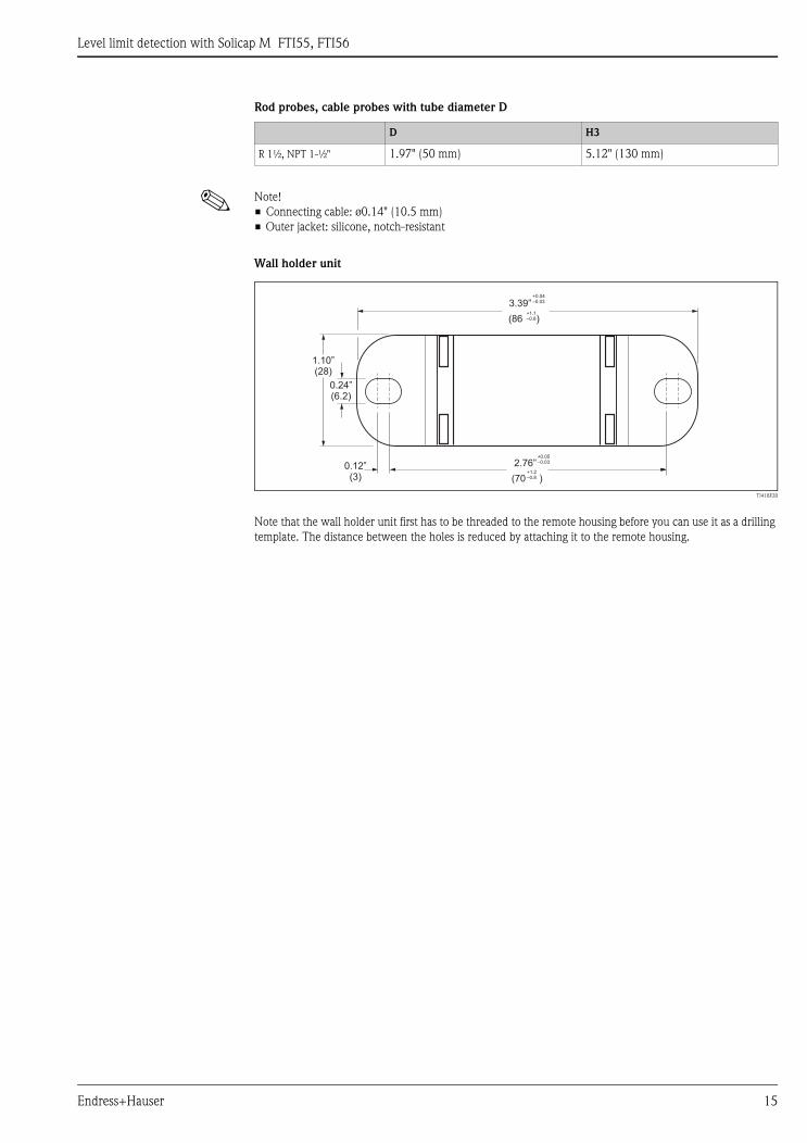
Rod probes, cable probes with tube diameter D
! Note!
• Connecting cable: ø0.14" (10.5 mm)
• Outer jacket: silicone, notch-resistant
Wall holder unit
D H3
R 1½, NPT 1-½" 1.97" (50 mm) 5.12" (130 mm)
TI418F20
Note that the wall holder unit first has to be threaded to the remote housing before you can use it as a drilling
template. The distance between the holes is reduced by attaching it to the remote housing.
+1.1–0.8
+0.04–0.03
+1.2–0.8
+0.05–0.03
0.12”(3)
1.10”(28)
2.76”
(70 )
(86 )
3.39”
0.24”(6.2)
Level limit detection with Solicap M FTI55, FTI56
16 Endress+Hauser
Operating conditions: Environment
Ambient temperature range • Ambient temperature of the transmitter: -58 to +158°F (-50°C to +70°C), note derating; see Page 17.
• A weather protection cover should be used when operating outdoors in strong sunlight. For further
information on the weather protection cover, see Page 38.
Storage temperature -58 to +185°F (-50°C to +85°C)
Climate class DIN EN 60068-2-38/IEC 68-2-38: test Z/AD
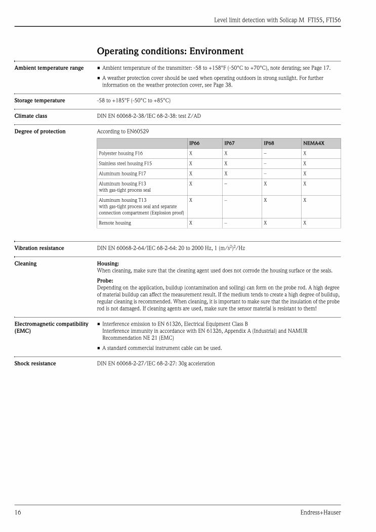
Degree of protection According to EN60529
Vibration resistance DIN EN 60068-2-64/IEC 68-2-64: 20 to 2000 Hz, 1 (m/s2)2/Hz
Cleaning Housing:
When cleaning, make sure that the cleaning agent used does not corrode the housing surface or the seals.
Probe:
Depending on the application, buildup (contamination and soiling) can form on the probe rod. A high degree
of material buildup can affect the measurement result. If the medium tends to create a high degree of buildup,
regular cleaning is recommended. When cleaning, it is important to make sure that the insulation of the probe
rod is not damaged. If cleaning agents are used, make sure the sensor material is resistant to them!
Electromagnetic compatibility
(EMC)
• Interference emission to EN 61326, Electrical Equipment Class B
Interference immunity in accordance with EN 61326, Appendix A (Industrial) and NAMUR
Recommendation NE 21 (EMC)
• A standard commercial instrument cable can be used.
Shock resistance DIN EN 60068-2-27/IEC 68-2-27: 30g acceleration
IP66 IP67 IP68 NEMA4X
Polyester housing F16 X X – X
Stainless steel housing F15 X X – X
Aluminum housing F17 X X – X
Aluminum housing F13
with gas-tight process seal
X – X X
Aluminum housing T13
with gas-tight process seal and separate
connection compartment (Explosion proof)
X – X X
Remote housing X – X X
Level limit detection with Solicap M FTI55, FTI56
Endress+Hauser 17
Operating conditions: Process
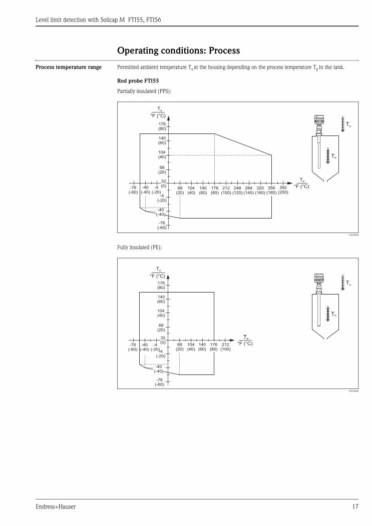
Process temperature range Permitted ambient temperature Ta at the housing depending on the process temperature Tp in the tank.
Rod probe FTI55
Partially insulated (PPS):
TI418F60
Fully insulated (PE):
TI418F60
Ta
32(0)
TP
176(80)
176(80)
248(120)
320(160)
392(200)
-76(-60)
-76(-60)
-4(-20)
-4(-20)
104(40)
104(40)
140(60)
140(60)
212(100)
284(140)
356(180)
TP
Ta
°F (°C)
°F (°C)
68(20)
68(20)
-40(-40)
-40(-40)
Ta
TP
TP
Ta
32(0)
176(80)
176(80)
-76(-60)
-76(-60)
-4(-20)
-4(-20)
104(40)
104(40)
140(60)
140(60)
212(100)
°F (°C)
°F (°C)
68(20)
68(20)
-40(-40)
-40(-40)

Level limit detection with Solicap M FTI55, FTI56
18 Endress+Hauser
Cable probe FTI56
Partially insulated (PTFE):
TI418F62
Fully insulated (PA):
TI418F63
Ta
0TP
248(120)
320(160)
392(200)
176(80)
176(80)
140(60)
140(60)
104(40)
104(40)
68(20)
-76(-60)
-76(-60)
-4(-20)
-4(-20)
212(100)
264(140)
356(180)
°F (°C)
°F (°C)
-40(-40)
TP
Ta
-40(-40)
68(20)
Ta
32(0)
-4(-20)
-4(-20)
-76(-60)
-76(-60)
176(80)
176(80)
140(60)
140(60)
104(40)
104(40)
68(20)
212(100)
TP
Ta
°F (°C)
-40(-40)
TP
284(140)
°F (°C)248(120)
68(20)
-40(-40)

Level limit detection with Solicap M FTI55, FTI56
Endress+Hauser 19
Process pressure and
temperature derating
Rod probe FTI55
Cable probe FTI56
Types of process medium See Page 4, "Application examples"
Partially insulated (PPS):
TI418F64
Fully insulated (PE):
TI418F65
Partially insulated (PTFE):
TI418F64
Fully insulated (PA):
TI418F66
psi (bar)
Pp
0
-40(-40)
-4(-20)
-76(-60)
176(80)
248(120)
320(160)
356(180)
392(200)
580(40)
290(20)
68(20)
104(40)
140(60)
212(100)
284(140)
TP
°F (°C)
32(0)
psi (bar)
Pp
-40(-40)
-4(-20)
-76(-60)
580 (40)
290 (20)
68(20)
104(40)
140(60)
176(80)
212(100)
TP
°F (°C)0
psi (bar)
Pp
0
-40(-40)
-4(-20)
-76(-60)
176(80)
248(120)
320(160)
356(180)
392(200)
580(40)
290(20)
68(20)
104(40)
140(60)
212(100)
284(140)
TP
°F (°C)
32(0)
psi (bar)
Pp
-40(-40)
-4(-20)
-76(-60)
176(80)
248(120)
580 (40)
290 (20)
68(20)
104(40)
140(60)
212(100)
284(140)
TP
°F (°C)0
Level limit detection with Solicap M FTI55, FTI56
20 Endress+Hauser
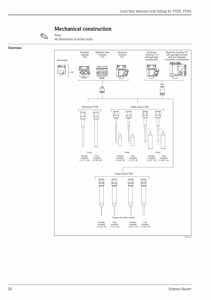
Mechanical construction
! Note!
All dimensions in inches (mm).
Overview
TI418Fen24
Electronics
Rod probe FTI55
Cable probe FTI56
Probes with inactive length
Partiallyinsulated
0.47” (12)�
Partiallyinsulated
0.47” (12)�
Partiallyinsulated
0.24” (6)�
Partiallyinsulated
0.24” (6)�
Partiallyinsulated
0.71” (18)�
ProbeProbe Probe
Fullyinsulated
0.55” (14)�
Fullyinsulated
0.55” (14)�
Fullyinsulated
0.31” (8)�
Fullyinsulated
0.31” (8)�
Fullyinsulated
0.98” (25)�
Cable probe FTI56
Polyesterhousing
F16
Stainless steelhousing
F15
Aluminumhousing
F17
Aluminumhousing F13with gas-tightprocess seal
Aluminum housing T13with gas-tight process
seal and separateconnection compartment
Level limit detection with Solicap M FTI55, FTI56
Endress+Hauser 21
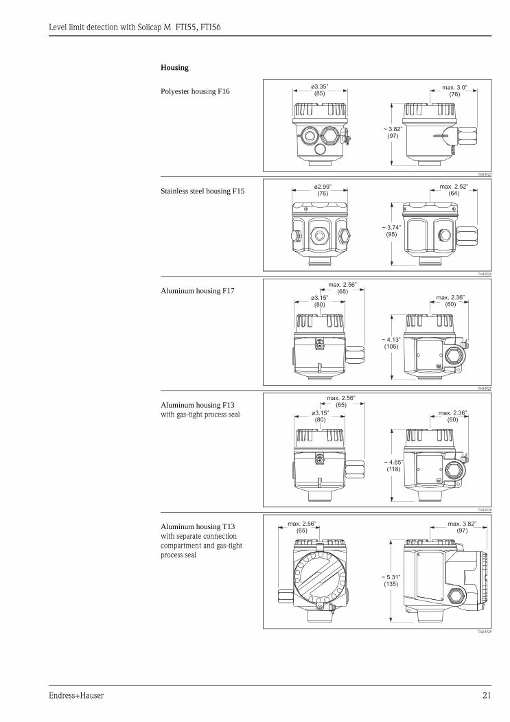
Housing
Polyester housing F16
TI418F25
Stainless steel housing F15
TI418F26
Aluminum housing F17
TI418F27
Aluminum housing F13with gas-tight process seal
TI418F28
Aluminum housing T13with separate connection
compartment and gas-tight
process seal
TI418F29
ø3.35”(85)
max. 3.0”(76)
~ 3.82”(97)
ø2.99”(76)
max. 2.52”(64)
~ 3.74”(95)
ø3.15”(80)
max. 2.36”(60)
max. 2.56”(65)
~ 4.13”(105)
ø3.15”(80)
max. 2.36”(60)
max. 2.56”(65)
~ 4.65”(118)
max. 2.56”(65)
max. 3.82”(97)
~ 5.31”(135)

Level limit detection with Solicap M FTI55, FTI56
22 Endress+Hauser
Housing extension heights with adapter
Process connections and flanges
Polyester housing
F16
Stainless steel
housing F15
Aluminum housing
F17
Aluminum housing
F13*
Aluminum housing
with separate
connection
compartment T13*
TI418F30 TI418F31 TI418F32 TI418F33 TI418F34
Order code 2 1 3 4 5
FTI55, FTI56
H1, inches (mm) 4.92 (125) 4.76 (121) 5.16 (131) 6.97 (177) 7.64 (194)
* Housing with gas-tight process seal
H1 H1 H1 H1 H1
Rod probe Cable probe Flanges
TI418Fen35
(DIN ISO228/I)
TI418Fen36
(ANSI B 1.20.1)
TI418F37
(EN1092-1)
(ANSI B 16.5)
(JIS B2220)
Thread R/NPT R/NPT
For pressures up to 362 psi (25 bar) 362 psi (25 bar) (depends on flange)
Version / order code R 1½ / RVJ
R 1½ / RV1
NPT 1½/ RGJ
NPT 1½ / RG1
R 1½ / RVJ
R 1½ / RV1
NPT 1½/ RGJ
NPT 1½ / RG1
ANSI 2" / AFJ
ANSI 3" / AGJ
ANSI 4" / AHJ
EN / B**
JIS / K**
Dimensions, inches (mm) H1 = 3.03 (77)
H2 = 0.98 (25)
AF = 50
H1 = 2.60 (66)
H2 = 0.98 (25)
AF = 50
H1 = 2.24" (57)
H1
H2
AF
H1
H2
AFH1

Level limit detection with Solicap M FTI55, FTI56
Endress+Hauser 23
Rod probes FTI55
! Note!
Total length of probe from start of thread: L = L1 + L3 (+4.92" / 125 mm with active buildup compensation)
Rod probe
partially insulated
Rod probe
fully insulated
Rod probe
with inactive length
partially/fully insulated
Rod probe
with active buildup
compensation
partially/fully insulated
TI418F38 TI418F39
Total length (L) 4" to 157" (100 to 4000) 4" to 157" (100 to 4000) 12" to 236" (300 to 6000) 4" to 157" (100 to 4000)
Active
rod length (L1)
4" to 157" (100 to 4000) 4" to 157" (100 to 4000) 4" to 157" (100 to 4000) 14" to 157" (100 to 4000)
Inactive
rod length (L3)
- - 8" to 78" (200 to 2000) -
Length of partial insulation (L2) 2.95" (75) - - / 2.95" (75) - / 2.95" (75)
Probe rod diameter
+ insulation thickness inches (mm)
0.71 (18)
0.14 (3.5)
0.71 (18)
0.14 (3.5)
0.71 (18)
0.14 (3.5)
0.71 (18)
0.14 (3.5)
ø Active buildup compensation
Length inches (mm)- / - - / - - / -
1.42 (36)
4.92 (125)
Lateral loading capacity lbf ft (Nm) at
68°F (20°C)
221 (300) 221 (300) 221 (300) 148 (200)
Maximum process temperature 356°F (180°C) 176°F (80°C) 176/356°F (80/180°C) 176/356°F (80/180°C)
For use in mounting nozzles - - X -
In the event of condensate on tank
ceiling
- - X -
X = recommended
L1/L2/L3
NPT / R
L1
L2
L1
L3
L2
L1
4.92”(125)
L2
L1
Length tolerance Up to 3 ft (1 m):
0 to -0.2" (–5 mm)
3 ft to 10 ft (1 m to 3 m):
0 to -0.39" (–10 mm)
10 ft to 20 ft (3 m to 6 m):
0 to -0.78" (–20 mm)

Level limit detection with Solicap M FTI55, FTI56
24 Endress+Hauser
Cable probes FTI56
! Note!
Total length of probe from start of thread: L = L1 + L3
Cable probe
partially insulated
Cable probe
Fully insulated
Cable probe
with inactive length
partially insulated
Cable probe
with inactive length
Fully insulated
TI418F38TI418F40
Total length (L) 20 to 866" (500 to 22000) 20 to 866" (500 to 22000) 20 to945" (500 to 24000) 20 to945" (500 to 24000)
Active cable length (L1) 20 to 866" (500 to 22000) 20 to 866" (500 to 22000) 20 to 866" (500 to 22000) 20 to 866" (500 to 22000)
Length of partial insulation (L2)* 20" (500) - 20" (500) 20" (500)
Inactive length (L3) - - 8 to 78" (200 to 2000) 8 to 78" (200 to 2000)
Probe cable diameter
+ insulation thickness, inches (mm)
0.24 (6 )
0.04 (1)
0.47 (12)
0.08 (2)
0.24 (6 )
0.04 (1)
0.47 (12)
0.04 (1)
0.24 (6 )
0.04 (1)
0.47 (12)
0.08 (2)
0.24 (6 )
0.04 (1)
0.47 (12)
0.04 (1)
ø Tensioning weight, inches (mm) 1.18 (30) 1.57 (40) 1.18 (30) 1.57 (40) 1.18 (30) 1.57 (40) 1.18 (30) 1.57 (40)
Length of tensioning weight (lg) in
inches (mm)
6 (150) 10 (250) 6 (150) 10 (250) 6 (150) 10 (250) 6 (150) 10 (250)
Tensile loading capacity in lbf (kN) of
probe cable at 68°F (20°C)
6744 (30) 13488 (60) 6744 (30) 13488 (60) 6744 (30) 13488 (60) 6744 (30) 13488 (60)
Maximum process temperature 356°F (180°F) 248°F (120°C) 356°F (180°F) 248°F (120°C)
For use in mounting nozzles - - X X
In the event of condensate on tank
ceiling
- - X X
X = recommended
* The length of the partial insulation extends, at maximum, to the tensioning weight.
L1/L2/L3
NPT / R
L1
L2
L1
L3
L2
L1
L3
lg lg lg lg
L1
Length tolerance Up to 3 ft (1 m): 0 to -0.39"
(0 to –10 mm)
3ft to 10 ft (1 m to 3 m):
0 to -0.79" (0 to –20 mm)
10 ft to 20 ft (3 m to 6 m):
0 to -1.18" (0 to –30 mm)
20 ft to 78 ft (6 m to 24 m):
0 to -1.57" (0 to –40 mm)

Level limit detection with Solicap M FTI55, FTI56
Endress+Hauser 25
Technical data (probe) Probe capacitance
Mount the probe at a minimum distance of 20" (500 mm) from a conductive container wall:
• Probe rod: approx. 1.3 pF/4" (100 mm) in air
• Probe rope: approx. 1.0 pF/4" (100 mm) in air
Material Housing
• Aluminum housing F17, F13, T13: GD–Al Si 10 Mg, DIN 1725, with plastic coating (blue/gray)
• Polyester housing F16: PBT–FR fiberglass reinforced polyester (blue/gray)
• Stainless steel housing F15: corrosion-resistant steel 316L (14404), uninsulated
Housing cover and seals
• Aluminum housing F17, F13, T13: EN-AC-AlSi10Mg, plastic-coated
Cover seal: EPDM
• Polyester housing F16: Cover made of PBT-FR or cover with sight glass made of PA12
Cover seal: EPDM
• Stainless steel housing F15: AISI 316L
Cover seal: silicone
Probe material
• Process connection, tensioning weight for cable probe: 1.4404 (316L SS) or steel
• Inactive length: 1.4404 (316L SS)
• Probe cable partially insulated: PTFE, 1.4401 (AISI 316 SS)
• Probe cable fully insulated: PA, galvanized steel
• Probe rod partially insulated: PPS, 1.4404 (316L SS)
• Probe rod fully insulated: PE, galvanized steel
Weight • with F15, F16, F17 or F13 housing approx. 9 lb (4.0 kg)
+ flange weight or process connection
+ probe rod 4 lb/3 ft (2.0 kg/m), for ø0.71" (18 mm) probe rod or
+ probe cable 0.4 lb/3 ft (0.180 kg/m), for ø0.24" (6 mm) cable probes, or
+ probe cable 1.2 lb/3 ft (0.550 kg/m) for ø0.47" (12 mm) cable probes
• with T13 housing approx. 10 lb (4.5 kg)
+ flange weight or process connection
+ probe rod 4 lb/3 ft (2.0 kg/m), for ø0.71" (18 mm) probe rod or
+ probe cable 0.4 lb/3 ft (0.180 kg/m ), for ø0.24" (6 mm) cable probes, or
+ probe cable 1.2 lb/3 ft (0.550 kg/m) for ø0.47" (12 mm) cable probes
Level limit detection with Solicap M FTI55, FTI56
26 Endress+Hauser
Input
Measured variable Capacitance change between the probe rod and the tank wall, depending on the level of the bulk solids.
Measuring range
(valid for all FEI5x)
• Measuring frequency:
500 kHz
• Span:
ΔC = 0 to 1600 pF
• Final capacitance:
CE = max. 1600 pF
• Adjustable initial capacitance:
CA = 0 to 500 pF (range 1 = factory setting)
CA = 0 to 1600 pF (range 2)
Input signal Probe covered => high capacitance
Probe not covered => low capacitance
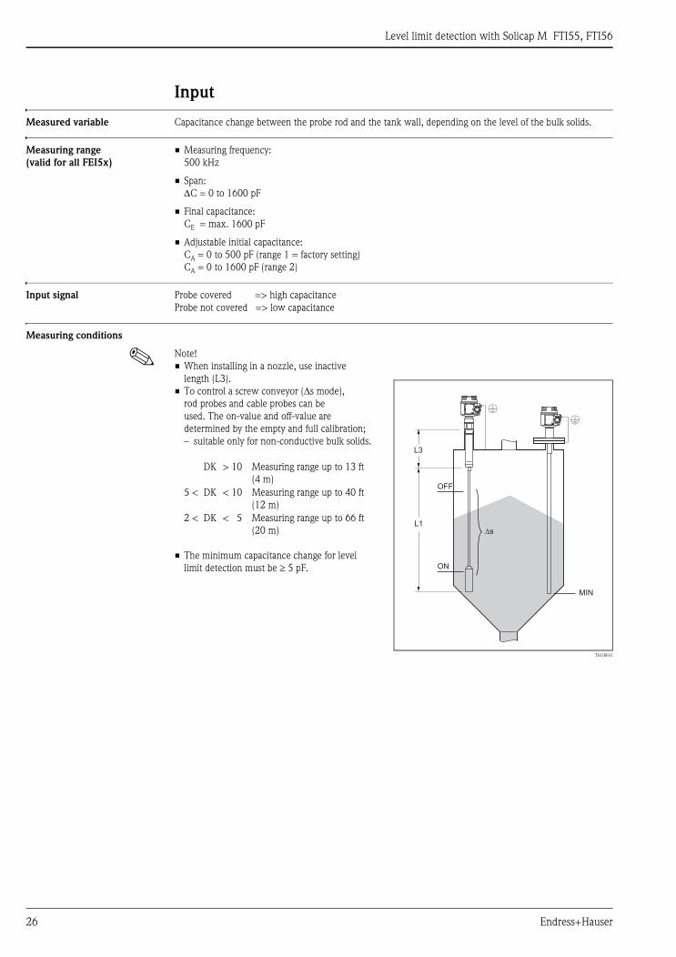
Measuring conditions
! Note!
• When installing in a nozzle, use inactive
length (L3).
• To control a screw conveyor (Δs mode),
rod probes and cable probes can be
used. The on-value and off-value are
determined by the empty and full calibration;
– suitable only for non-conductive bulk solids.
• The minimum capacitance change for level
limit detection must be ≥ 5 pF.
DK > 10 Measuring range up to 13 ft
(4 m)
5 < DK < 10 Measuring range up to 40 ft
(12 m)
2 < DK < 5 Measuring range up to 66 ft
(20 m)
TI418F41
L3
L1
MIN
OFF
ON
�s

Level limit detection with Solicap M FTI55, FTI56
Endress+Hauser 27
Output
Galvanic isolation FEI52:
Between rod probe and power supply
FEI54:
Between rod probe, power supply and load
FEI53, FEI55, FEI57S:
See connected switching device (functional galvanic isolation in the electronic insert)
Switch behavior Binary or Δs mode (e.g. controlling a screw conveyor)
Switch-on behavior When the power supply is switched on, the switching status of the outputs corresponds to the signal on alarm.
The correct switching status is achieved after max. 3 seconds.
Failsafe mode Minimum/maximum quiescent current safety can be switched at the electronic insert (for FEI53 and FEI57S
only in Nivotester FTC)
MIN = minimum safety: The output switches safety-oriented when the probe is uncovered (signal on alarm).
Used for dry-running protection and screw conveyor, for example
MAX = maximum safety: The output switches safety-oriented when the probe is covered (signal on alarm).
For use with overfill protection for example
Switching delay FEI52, FEI54, FEI55:
Can be adjusted incrementally in the electronic insert: 0.3 to 10 s
FEI53, FEI57S:
Depends on the connected Nivotester transmitter

Level limit detection with Solicap M FTI55, FTI56
28 Endress+Hauser
FEI52 electronic insert (DC PNP)
Power supply Supply voltage: 10 to 55 V DC
Ripple: max. 1.7 V, 0 to 400 Hz
Current consumption: < 20 mA
Power consumption without load: max. 0.9 W
Power consumption with full load (350 mA): 1.6 W
Reverse polarity protection: yes
Separation voltage: 3.7 kV
FEI52 overvoltage protection: overvoltage category III
Electrical connection Three-wire DC connection
Output signal
Signal on alarm Output signal on power failure or in the event of device failure: IR < 100 μA
Connectable load • Load switched via transistor and separate PNP connection, max. 55 V
• Load current max. 350 mA (cyclical overload and short-circuit protection)
• Residual current < 100 μA (with transistor blocked)
• Capacitive load max. 0.5 μF at 55 V; max. 1.0 μF at 24 V
• Residual voltage < 3 V (for transistor switched through)
Preferably in conjunction with programmable logic
controllers (PLC), DI modules in accordance with
EN 61131-2.
Positive signal present at the switch output of the
electronic system (PNP).
TI418F42
1 2 3
L+ L–
(+)
–
F0.5A R
FEI52
U – 10 to 55 V (DC)…
TI418Fen43
IL = Load current
(switched through)
IR = Residual current
(blocked)
TI418F44
Lit
Flashes
Unlit
L+ +1 3
L+ +1 3
1 3
1 3
1 3
1 3
IL
IL
IR
IR
IR
I / IL
MAX
MIN
Instrument failure
Maintenancerequired *
Safety mode Level Output signal LEDsgreen red yellow

Level limit detection with Solicap M FTI55, FTI56
Endress+Hauser 29
Electronic insert FEI53 (3-wire)
Power supply Supply voltage: 14.5 V DC
Current consumption: < 15 mA
Power consumption: max. 230 mW
Reverse polarity protection: yes
Separation voltage: 0.5 kV
Electrical connection Three-wire DC connection
Output signal
Signal on alarm Voltage at terminal 3: < 2.7 V
Connectable load • Floating relay contacts in the connected switching unit Nivotester FTC325 3-WIRE
• For the contact load capacity, refer to the technical data of the switching device.
3 to 12 V signal
For connecting to the switching unit, Nivotester
FTC325 3–WIRE from Endress+Hauser.
Switching between minimum/maximum
Safety in the Nivotester FTC325 3-WIRE.
Level limit adjustment directly at the Nivotester.
TI418F45
12 11 13– + S
Nivotester FTC325 3-WIRE
1 2 3
(+)
FEI53
TI418Fen46 TI418F44
Lit
Flashes
Unlit
Mode
Instrument failure
Maintenancerequired *
Output signal
Normal operation
< 2.7 V3at terminal
3 to 12 Vat terminal 3
3 to 12 V3at terminal
LEDsgreen red

Level limit detection with Solicap M FTI55, FTI56
30 Endress+Hauser
FEI54 electronic insert (AC/DC with relay output)
Power supply Supply voltage: 19 to 253 V AC, 50/60 Hz or 19 to 55 V DC
Power consumption: max. 1.6 W
Reverse polarity protection: yes
Separation voltage: 3.7 kV
FEI54 overvoltage protection: overvoltage category III
Electrical connection Universal current connection with relay output (DPDT)
Output signal
Signal on alarm Output signal on power failure or in the event of device failure: relay de-energized
Connectable load • Loads switched via 2 floating changeover contacts (DPDT)
• I~ max. 6 A, U~ max. 253 V; P~ max. 1500 VA at cos ϕ = 1, P~ max. 750 VA at cos ϕ > 0.7
• I– max. 6 A to 30 V, I– max. 0.2 A to 125 V
• The following applies when connecting a functional low-voltage circuit with double isolation as per IEC 1010:
Sum of voltages of relay output and power supply max. 300 V
Power supply:
Please note the different voltage ranges
for AC and DC.
Alternating current.
Output:
When connecting an instrument with high
inductance, provide a spark arrester to protect
the relay contact.
A fine-wire fuse (depending on the load connected)
protects the relay contact on short-circuiting.
Both relay contacts switch simultaneously.
* See below "Connectable load"
TI418F47
U~ 19 to 253 VU– 19 to 55 V
(AC)(DC)
L1L+
NO NOC CNC NC
*NL–
PE(Ground)
F0.5A
1 2 6 7 83 4 5
FEI54
*
TI418Fen48 TI418F49
Relay energized
Relay de-energized
Lit
Flashes
Unlit3 54 6 87
3 54 6 87
3 54
3 54
6 87
6 87
3 54 6 87MAX
MIN
Instrument failure
Maintenancerequired *
Safety mode Level Output signal LEDsgreen red yellow

Level limit detection with Solicap M FTI55, FTI56
Endress+Hauser 31
FEI55 electronic insert (8/16 mA)
Power supply Supply voltage: 11 to 36 V DC
Power consumption: < 600 mW
Reverse polarity protection: yes
Separation voltage: 0.5 kV
Electrical connection Two-wire connection for separate switching unit
Output signal
Signal on alarm Output signal on power failure or in the event of device failure: < 3.6 mA
Connectable load • U = connection DC voltage 11 to 36 V
• Imax = 16 mA
For connecting to programmable logic controllers
(PLC), AI modules 4 to 20 mA in accordance
with EN 61131–2.
The level limit signal is sent via an output signal
jump from 8 mA to 16 mA.
TI418Fen50
1 2
Intrinsicallysafe
Non-hazardousarea
FEI55
–
U– 11 to 36
+
EX
EX
e.g. PLC
TI418Fen51
~16 mA = 16 mA ± 5 %
~ 8 mA = 8 mA ± 6 %
TI418F44
Lit
Flashes
Unlit
MAX
MIN
+2 1
+2 1
+2 1
+2 1
~16 mA
~8 mA
~8 mA
~16 mA
+2 1
8/16 mA
+2 1
< 3.6 mAInstrument failure
Maintenancerequired *
Safety mode Level Output signal LEDsgreen red yellow
Level limit detection with Solicap M FTI55, FTI56
32 Endress+Hauser
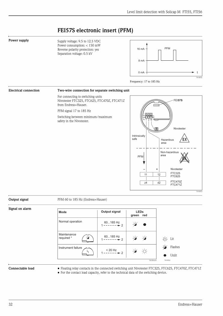
FEI57S electronic insert (PFM)
Power supply
Electrical connection Two-wire connection for separate switching unit
Output signal PFM 60 to 185 Hz (Endress+Hauser)
Signal on alarm
Connectable load • Floating relay contacts in the connected switching unit Nivotester FTC325, FTC625, FTC470Z, FTC471Z
• For the contact load capacity, refer to the technical data of the switching device.
Supply voltage: 9.5 to 12.5 VDC
Power consumption: < 150 mW
Reverse polarity protection: yes
Separation voltage: 0.5 kV
TI418F52
Frequency: 17 to 185 Hz
0 mA
8 mA
16 mA PFM
t
For connecting to switching units
Nivotester FTC325, FTC625, FTC470Z, FTC471Z
from Endress+Hauser.
PFM signal 17 to 185 Hz
Switching between minimum/maximum
safety in the Nivotester.
TI418F53
– +
11 12
z4 d2
PFM
EX
EX
Intrinsicallysafe Hazardous
area
Non-hazardousarea
1 2
FEI57S
FTC325FTC625
FTC470ZFTC471Z
Nivotester
Nivotester
TI418Fen54 TI418F44
Lit
Flashes
Unlit
1 2
1 2< 20 Hz
60...185 Hz
1 260...185 Hz
Mode
Instrument failure
Maintenancerequired *
Output signal
Normal operation
LEDsgreen red

Level limit detection with Solicap M FTI55, FTI56
Endress+Hauser 33
Power supply
Electrical connection Connection compartment
Five housings with the following protection classes are available:
Cable entry • Cable gland: M20x1.5
Two cable glands are included with each unit.
• Cable entry: M20, G ½ or NPT ½, NPT ¾
Performance characteristics
Reference operating • Temperature: 68°F ± 41°F (+20°C ± 5°C)
• Pressure: 15 psia ± 0.3 psi (1013 mbar abs. ± 20 mbar)
• Humidity: 65% ± 20%
Switchpoint deviation Reproducibility: 0.1% (related to the probe length)
Influence of ambient
temperature
Electronic insert
< 0.06% / 10 K related to the full scale value
Remote housing
Capacitance change in connecting cable 0.015 pF/mK
Standard Intrinsically safe Dust ignition-proof Gas-tight process seal
Plastic housing F16 X – – –
Stainless steel housing F15 X X X –
Aluminum housing F17 X X X –
Aluminum housing F13 X X X X
Aluminum housing T13
(with separate connection
compartment)
X X X X

Level limit detection with Solicap M FTI55, FTI56
34 Endress+Hauser
Human interface
Electronic inserts FEI52, FEI54, FEI55
• green LEDs ( operational status)
• Red LED ( fault message)
• Yellow LED (✲ switching status)
• Key (–)
• Key (+)
• Mode switch (position 1-8)
– 1: Operation
– 2: Calibration (empty/full)
– 3: Switchpoint adjustment
– 4: Measuring range setting
Controlling a screw conveyor, Δs mode
– 5: Switching delay
– 6: Self-test
– 7: Failsafe mode (MIN/MAX)
– 8: Configuration/upload, download
TI418F55
! Note!
To execute the various functions, press and hold the
key for at least 2 seconds.
BA300Fen002
FEI53, FEI57S
• Green LED ( operational status)
• Red LED ( fault message)
• DIP switch (left),
– Standard: If the measuring range is exceeded
no alarm is output
– : If the measuring range is exceeded
an alarm is output.
• DIP switch (right), span
– Range 1: 0 to 500 pF
– Range 2: 0 to 1600 pFTI418F57
- ++-
FEI558/16mA11...36V DC
7 3
5
I=16mA
1
2
3
4
5
6
7
8
_ +
Δc
Δs
MIN MAX
down-load
up-load
0.3
s1.5
s5
s10
s
2 4 8 16 32 pf
500
1600 pf
off on
1
7 3
5
build-up
active
Operation
Reset to factorysettings
Empty calibration
Full calibration
Switchpointadjustment
Measurementrange, small/big
Two-point controlBuild-up mode
Switching delay
Minimum/maximum failsafe
Device self test(Proof test)
pressfor
up-load
pressfor
down-load
Mode Key Key
press together for20 sec.
press
press
press2 x
press for<
press for<
press together
press forMIN
press forMAX
LED SignalsFunction/ModeSymbol
press
Up-DownloadSensor EEPROM
press for>
press for>
- +
FEI57SPFM
0.....500pF0.....500pFStandardStandard
0...1600pF0...1600pF

Level limit detection with Solicap M FTI55, FTI56
Endress+Hauser 35
Certificates and approvals
CE approval The devices are designed to meet state-of-the-art safety requirements, have been tested and left the factory in
a condition in which they are safe to operate. The devices comply with the applicable standards and regulations
that are listed in the EC Declaration of Conformity and thus meet the legal requirements of the EC Directives.
Endress+Hauser confirms the conformity of the device by affixing to it the CE approval.
Hazardous approvals See "Ordering information"
Other standards and
guidelines
EN 60529
Degrees of protection by housing (IP code)
EN 61010
Protection measures for electrical equipment for measurement, control, regulation and laboratory
procedures
EN 61326
Interference emission (Class B equipment), interference immunity (Appendix A - Industrial)
NAMUR
Association for Standards for Control and Regulation in the Chemical Industry
Ordering information
Solicap M FTI55 10 Approval:
A Non-hazardous areas
B ATEX II 1/3 D
C ATEX II 1/2 D
D ATEX II 3 D EEx nA/nL/nC
F ATEX II 1 D, II 1/2 GD EEx ia IIC T6
K CSA General Purpose, CSA C US
L CSA/FM IS Cl. I, II, III, Div. 1+2, Gr. A-G
M CSA/FM XP Cl. I, II, III, Div. 1+2, Gr. A-G
N CSA/FM DIP Cl. I, II, III, Div. 1+2, Gr. E-G
S TIIS Ex ia IIC T3
T TIIS Ex d IIC T3
Y Special version, to be specified
20 Inactive length L3:
A Not selected
B Not selected + 125 mm/5 inch
Active buildup compensation
316L
1 .... mm 316L
5 .... inch 316L
9 Special version
30 Active length L1:
A .... mm, steel
B 325 mm, steel
C .... mm, 316L
D 325 mm, 316L
H .... inch, steel
K 13 inch, steel
M .... inch, 316L
N 13 inch, 316L
Y Special version, to be specified
40 Insulation:
1 fully insulated PE, max. 176°F (80°C)
2 75 mm L2, partially insulated PPS, max. 356°F (180°C)
3 3 inch L2, partially insulated PPS, max. 356°F (180°C)
9 Special version, to be specified

Level limit detection with Solicap M FTI55, FTI56
36 Endress+Hauser
50 Process connection:
AFJ 2", 150 lbs RF 316/316L
AGJ 3", 150 lbs RF 316/316L
AHJ 4", 150 lbs RF 316/316L
BSJ DN80, PN10/16 A 316L EN1092-1 (DIN2527 B)
BTJ DN100, PN10/16 A 316L EN1092-1 (DIN2527 B)
B3J DN50, PN25/40 A 316L EN1092-1 (DIN2527 B)
KFJ 10K 50, RF 316L JIS B2220
KGJ 10K 80, RF 316L JIS B2220
KHJ 10K 100, RF 316L JIS B2220
RGJ NPT 1½, 316L thread ANSI
RG1 NPT 1½, steel thread ANSI
RVJ R 1½, 316L thread DIN2999
RV1 R 1½, steel thread DIN2999
YY9 Special version, to be specified
60 Electronics; output:
W Prepared for FEI5x
Y Special version, to be specified
2 FEI52; 3-wire PNP, 10 to 55 V DC
3 FEI53; 3-wire, 3 to 12 V signal
4 FEI54; relay DPDT, 19 to 253 V AC, 19 to 55 V DC
5 FEI55; 8/16 mA, 11 to 36 V DC
7 FEI57S; 2-wire PFM
70 Housing:
1 F15 316L IP66, NEMA4X
2 F16 polyester IP66, NEMA4X
3 F17 aluminum IP66, NEMA4X
4 F13 Alu + gas-tight probe seal IP66, NEMA4X
5 T13 Alu + gas-tight probe seal
+ separate connection compartment
IP66, NEMA4X
9 Special version, to be specified
80 Cable entry:
A M20 Threaded joint
B Thread G ½
C Thread NPT ½
D Thread NPT ¾
G Thread M20
Y Special version, to be specified
90 Probe design:
1 Compact
2 2000 mm L4 cable > separate housing
3 .... mm L4 cable > separate housing
4 80 inch L4 cable > separate housing
5 .... inch L4 cable > separate housing
9 Special version, to be specified
100 Additional equipment:
A Basic version
D EN10204-3.1 material (316L wetted), Inspection certificate
E EN10204-3.1 material (316L wetted),
NACE MR0175
Inspection certificate
Y Special version, to be specified
FTI55 Product designation
Level limit detection with Solicap M FTI55, FTI56
Endress+Hauser 37
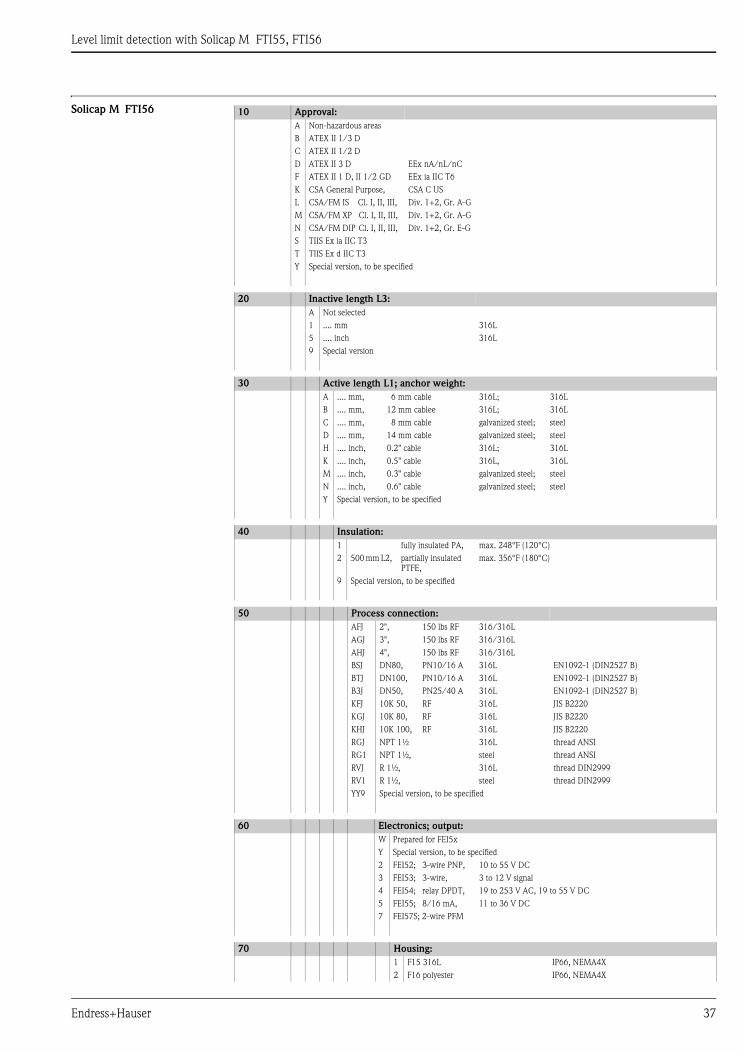
Solicap M FTI56 10 Approval:
A Non-hazardous areas
B ATEX II 1/3 D
C ATEX II 1/2 D
D ATEX II 3 D EEx nA/nL/nC
F ATEX II 1 D, II 1/2 GD EEx ia IIC T6
K CSA General Purpose, CSA C US
L CSA/FM IS Cl. I, II, III, Div. 1+2, Gr. A-G
M CSA/FM XP Cl. I, II, III, Div. 1+2, Gr. A-G
N CSA/FM DIP Cl. I, II, III, Div. 1+2, Gr. E-G
S TIIS Ex ia IIC T3
T TIIS Ex d IIC T3
Y Special version, to be specified
20 Inactive length L3:
A Not selected
1 .... mm 316L
5 .... inch 316L
9 Special version
30 Active length L1; anchor weight:
A .... mm, 6 mm cable 316L; 316L
B .... mm, 12 mm cablee 316L; 316L
C .... mm, 8 mm cable galvanized steel; steel
D .... mm, 14 mm cable galvanized steel; steel
H .... inch, 0.2" cable 316L; 316L
K .... inch, 0.5" cable 316L, 316L
M .... inch, 0.3" cable galvanized steel; steel
N .... inch, 0.6" cable galvanized steel; steel
Y Special version, to be specified
40 Insulation:
1 fully insulated PA, max. 248°F (120°C)
2 500 mm L2, partially insulated
PTFE,
max. 356°F (180°C)
9 Special version, to be specified
50 Process connection:
AFJ 2", 150 lbs RF 316/316L
AGJ 3", 150 lbs RF 316/316L
AHJ 4", 150 lbs RF 316/316L
BSJ DN80, PN10/16 A 316L EN1092-1 (DIN2527 B)
BTJ DN100, PN10/16 A 316L EN1092-1 (DIN2527 B)
B3J DN50, PN25/40 A 316L EN1092-1 (DIN2527 B)
KFJ 10K 50, RF 316L JIS B2220
KGJ 10K 80, RF 316L JIS B2220
KHJ 10K 100, RF 316L JIS B2220
RGJ NPT 1½ 316L thread ANSI
RG1 NPT 1½, steel thread ANSI
RVJ R 1½, 316L thread DIN2999
RV1 R 1½, steel thread DIN2999
YY9 Special version, to be specified
60 Electronics; output:
W Prepared for FEI5x
Y Special version, to be specified
2 FEI52; 3-wire PNP, 10 to 55 V DC
3 FEI53; 3-wire, 3 to 12 V signal
4 FEI54; relay DPDT, 19 to 253 V AC, 19 to 55 V DC
5 FEI55; 8/16 mA, 11 to 36 V DC
7 FEI57S; 2-wire PFM
70 Housing:
1 F15 316L IP66, NEMA4X
2 F16 polyester IP66, NEMA4X
Level limit detection with Solicap M FTI55, FTI56
38 Endress+Hauser
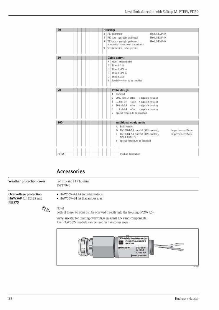
Accessories
Weather protection cover For F13 and F17 housing
TSP17090
Overvoltage protection
HAW569 for FEI55 and
FEI57S
• HAW569–A11A (non-hazardous)
• HAW569–B11A (hazardous area)
! Note!
Both of these versions can be screwed directly into the housing (M20x1.5).
Surge arrester for limiting overvoltage in signal lines and components.
The HAW562Z module can be used in hazardous areas.
TI418F58
3 F17 aluminum IP66, NEMA4X
4 F13 Alu + gas-tight probe seal IP66, NEMA4X
5 T13 Alu + gas-tight probe seal
+ separate connection compartment
IP66, NEMA4X
9 Special version, to be specified
80 Cable entry:
A M20 Threaded joint
B Thread G ½
C Thread NPT ½
D Thread NPT ¾
G Thread M20
Y Special version, to be specified
90 Probe design:
1 Compact
2 2000 mm L4 cable > separate housing
3 .... mm L4 cable > separate housing
4 80 inch L4 cable > separate housing
5 .... inch L4 cable > separate housing
9 Special version, to be specified
100 Additional equipment:
A Basic version
D EN10204-3.1 material (316L wetted), Inspection certificate
E EN10204-3.1 material (316L wetted),
NACE MR0175
Inspection certificate
Y Special version, to be specified
FTI56 Product designation
70 Housing:
ÜS-Ableiter/ArresterÜS-Ableiter/ArresterENDRESS+HAUSERENDRESS+HAUSERHAHAW569W569
HAHAW569-A1W569-A1 Uc 34.8 VUc 34.8 VIn 10 kAIn 10 kAILIL 500 mA500 mA
protectedprotected
Level limit detection with Solicap M FTI55, FTI56
Endress+Hauser 39
Spare parts Electronic insert
• FEI52 electronic insert: 71025819
• FEI53 electronic insert: 71025820
• FEI54 electronic insert: 71025814
• FEI55 electronic insert: 71025815
• FEI57S electronic insert: 71025816
Cover for housing
• Cover for aluminum housing F13, gray with sealing ring: 52002698
• Cover for stainless steel housing F15, with sealing ring: 52027000
• Cover for stainless steel housing F15, with clasp and sealing ring: 52028268
• Cover for polyester housing (F16), transparent plastic with seal: 52025790
• Cover for polyester housing F16, flat: gray with sealing ring: 52025606
• Cover for aluminum housing F17, flat: with sealing ring: 52002699
• Cover for aluminum housing T13 flat, electronics compartment: gray with sealing ring: 52006903
• Cover for aluminum housing T13 flat, connection compartment: gray with sealing ring: 52007103
Seal set for stainless steel housing
• Seal set for stainless steel housing F15: with 5 sealing rings: 52028179
Documentation
! Note!
This documentation is available on the product pages at www.endress.com
Technical Information • Fieldgate FXA320, FXA520
TI369F/00/en
Operating Instructions • Solicap M FTI55, FTI56
BA300F/00/en
Safety information (ATEX) • Solicap M FTI55, FTI56
ATEX II 1 D Ex tD A20 IP65 T 90 °C,
ATEX II 1/2 D Ex tD A20/A21 IP65 T 100 °C
XA389F/00/a3
Control drawings
• Solicap M FTI55, FTI56
FM
• Solicap M FTI55, FTI56
CSA
Patents This product is protected by at least one of the patents listed below.
Further patents are under development.
• DE 203 00 901 U1
• DE 103 22 279,
WO 2004 102 133,
US 2005 003 9528
• DE 203 13 695,
WO 2005 025 015

Level limit detection with Solicap M FTI55, FTI56
40 Endress+Hauser
Mexico
Endress+Hauser, México, S.A. de C.V.
Av. Gustavo Baz No. 43
Fracc. Bosques de Echegaray
Naucalpan de Juárez, C.P. 53310, Estado
de México
México
Tel: (52) 55-5371-1110
Fax (52) 55-5371-1128
United States
Endress+Hauser, Inc.
2350 Endress Place
Greenwood, IN 46143
Tel. 317-535-7138
Sales 888-ENDRESS
Service 800-642-8737
fax 317-535-8498
www.us.endress.com
TI418F/24/ae/12.06
© 2006 Endress+Hauser
Canada
Endress+Hauser Canada
1075 Sutton Drive
Burlington, ON L7L 5Z8
Tel. 905-681-9292
800-668-3199
Fax 905-681-9444
www.ca.endress.com

![Untitled-6 [] yamato.pdf · tis 1390-2539 (1996) tis 1390-2539 (1996) tis 1227-2539 (1996) tis 1227-2539 (1996) tis 1227-2539 (1996) tis 1227-2539 (1996)](https://img.pdfslide.net/doc/110x75/5f7cd919128bf72d7a0d9590/untitled-6-yamatopdf-tis-1390-2539-1996-tis-1390-2539-1996-tis-1227-2539.jpg)


![Untitled-6 [] · tis 1227-2539 (1996) tis 1390-2539 (1996) tis 1227-2539 (1996) tis 1390-2539 (1996) tis 1227-2539 (1996)](https://img.pdfslide.net/doc/110x75/5e1a6a0f6b8d9f48bd19bcad/untitled-6-tis-1227-2539-1996-tis-1390-2539-1996-tis-1227-2539-1996-tis.jpg)