Embed Size (px)
Citation preview
1
For your convenience: the HELP button brings up this Instruction Manual. You can:
Put cursor on page number in Table of Contents; click to go to topic (cool!)
Use View/Zoom and arrow buttons to examine details of drawings
Use Edit/Find for word search
Print whole or part of manual if desired
Download the newest RFCP and manual from our website
MUST HAVE MS WORD INSTALLED ON YOUR COMPUTER
TECHNICAL INNOVATIONS, INC.
7851 Cessna Ave.
Gaithersburg, MD 20879
301-977-9000
301-977-1106 (FAX) [email protected]
RoboFocus™ (Temperature Compensated)
Version 3.X Firmware
Version 3.2.X Software
Jan. 6, 2003
Notice: This instruction manual may be used for all versions of RoboFocus. However,
versions of the RoboFocus Control Program (RFCP) dated prior to Nov 2001 will not
show the full range of capabilities of the system. We recommend that you download the
latest RFCP from our website (free) at www.homedome.com See Ch. 1.
CAUTION
Technical Innovations, Inc. is not responsible and assumes no liability for any damage or injury
arising from assembly or use of this product. While the instructions include cautions and warnings, it is
ultimately the customer who must exercise good judgment and care during assembly and operation to avoid
damage to materials or persons, and it is the customer who assumes all risk and liability. Under no
circumstances will Technical Innovations, Inc. be responsible for consequential damages to person or
property.
All portions of this instruction manual are copyrighted by Technical Innovations, Inc. 2002 and
are protected under the laws of the United States. This document may not be reproduced without the consent
of Technical Innovations, Inc. except for use by the purchaser.
2
Table of Contents
RoboFocus™ .......................................................................................................................................................................................... 1
1. Introduction ....................................................................................................................................................................................... 3
Introduction ........................................................................................................................................................................................ 3
A Little Theory ................................................................................................................................................................................... 3
Changes in RoboFocus V3. ................................................................................................................................................................ 4 Changes in RoboFocus V3.2 Software ............................................................................................................................................... 4
Changes in Controller from Model 3 to Model 3.1 ............................................................................................................................. 4
2. RoboFocus Installation ...................................................................................................................................................................... 5
RoboFocus Software........................................................................................................................................................................... 5
RoboFocus Hardware ......................................................................................................................................................................... 5
RoboFocus Electrical ........................................................................................................................................................................ 10 Serial Pass Through .......................................................................................................................................................................... 10
Remote Power Module ..................................................................................................................................................................... 11
Hand Control .................................................................................................................................................................................... 11 Remote Temperature Sensor ............................................................................................................................................................. 11
3. Operation of RoboFocus ................................................................................................................................................................. 12
Introduction ...................................................................................................................................................................................... 12
Initial Check – Motion Direction and Clutch .................................................................................................................................... 12
Local Operation. ............................................................................................................................................................................... 12
Remote Operation: Use of RoboFocus Control Program (RFCP) ..................................................................................................... 13 Main Control Screen .................................................................................................................................................................... 13
Configuration Screen ................................................................................................................................................................... 15
Manual Full Travel Calibration. ....................................................................................................................................................... 17 Manual Menu. .................................................................................................................................................................................. 17
Multiple Copies of Robofocus Running Multiple Controllers .......................................................................................................... 19 Trouble Shooting Guide ................................................................................................................................................................... 20
4. Temperature Compensation .......................................................................................................................................................... 21
Introduction ...................................................................................................................................................................................... 21 Manual Temperature Coefficient ...................................................................................................................................................... 22
Temperature Compensation Training. .............................................................................................................................................. 22
Temperature Compensation Operation. ............................................................................................................................................ 23 Operational Issues ............................................................................................................................................................................ 24
5. Focusing Strategies ......................................................................................................................................................................... 26
Introduction ...................................................................................................................................................................................... 26 Schmidt –Cassegrain Scopes ............................................................................................................................................................ 26
Automatic Focusing Strategies ......................................................................................................................................................... 27
Using CCDSoft @Focus ................................................................................................................................................................... 28 Using MaxIm DL ............................................................................................................................................................................. 29
Using FocusMax ............................................................................................................................................................................... 29
Temperature Training Using Autofocus. .......................................................................................................................................... 30 Changing Setups. .............................................................................................................................................................................. 30
ASCOM and Scripting ...................................................................................................................................................................... 31
Film Photography ............................................................................................................................................................................. 31
Appendix 1 Software Commands ...................................................................................................................................................... 32
Appendix 2 Schematic Diagram ........................................................................................................................................................ 34
Appendix 3 Serial Cables ................................................................................................................................................................... 35
Appendix 4 Serial Ports and Cables .................................................................................................................................................. 36
Introduction ...................................................................................................................................................................................... 36 Serial Cable Options ......................................................................................................................................................................... 36
Parallel Cable Options ...................................................................................................................................................................... 37
Multiple Serial Ports ......................................................................................................................................................................... 37 USB .................................................................................................................................................................................................. 37
Serial Port Expansion Cards ............................................................................................................................................................. 38
Serial Communications Troubleshooting .......................................................................................................................................... 39
Appendix 5 ASCOM Scripting ........................................................................................................................................................... 41
Functions that Return Settings: ......................................................................................................................................................... 41
Functions that Alter Settings: ........................................................................................................................................................... 42 Functions that Perform an Action: .................................................................................................................................................... 43
Appendix 6 Parts List ......................................................................................................................................................................... 45
Appendix 7 Ins Manual Revisions ..................................................................................................................................................... 45
3
1. Introduction
Introduction
The RoboFocus is a remote focus driver to be installed on your existing focus mechanism. RoboFocus
provides digital control and feedback of the focus position using a stepping motor controlled by a
microprocessor. The user sends commands from his computer to the RoboFocus to move the focus, and
receives back digital position information. RoboFocus can also be used to control four remote 120VAC
power outlets using the optional Remote Power Module. The software to control the RoboFocus provides a
graphical interface, and is open source VB operating under Windows. It includes full ASCOM scripting
capability. The user may also write code to control the focuser.
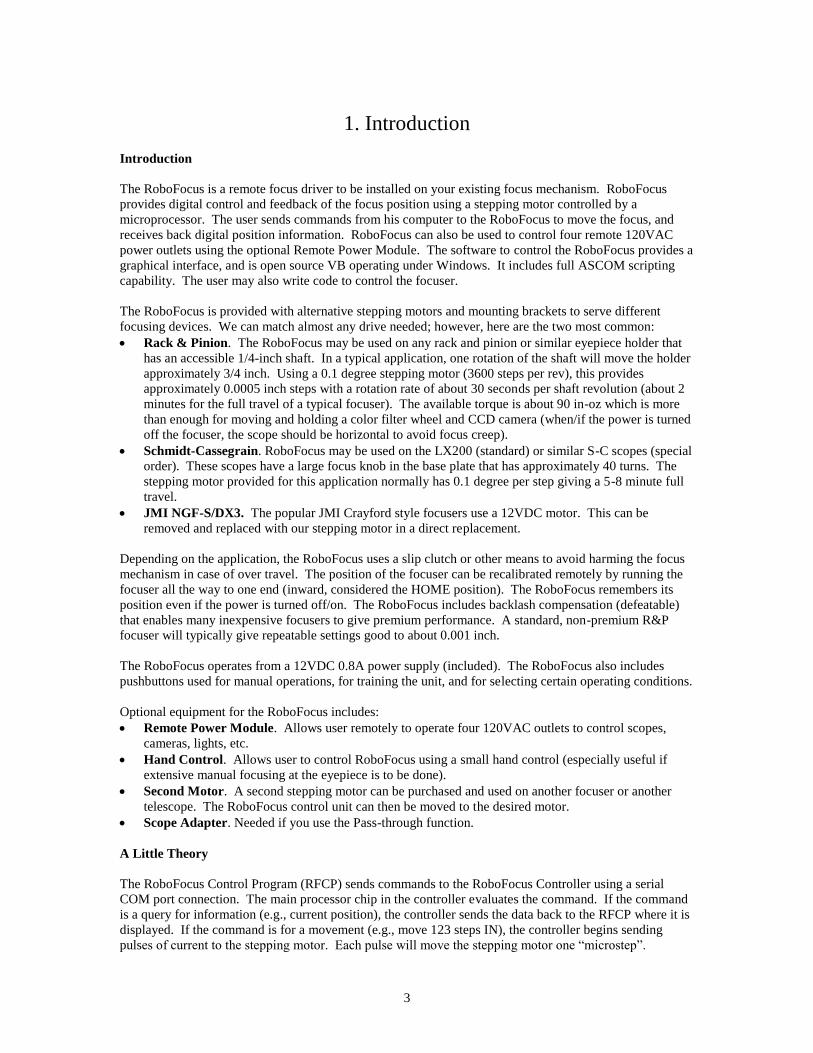
The RoboFocus is provided with alternative stepping motors and mounting brackets to serve different
focusing devices. We can match almost any drive needed; however, here are the two most common:
Rack & Pinion. The RoboFocus may be used on any rack and pinion or similar eyepiece holder that
has an accessible 1/4-inch shaft. In a typical application, one rotation of the shaft will move the holder
approximately 3/4 inch. Using a 0.1 degree stepping motor (3600 steps per rev), this provides
approximately 0.0005 inch steps with a rotation rate of about 30 seconds per shaft revolution (about 2
minutes for the full travel of a typical focuser). The available torque is about 90 in-oz which is more
than enough for moving and holding a color filter wheel and CCD camera (when/if the power is turned
off the focuser, the scope should be horizontal to avoid focus creep).
Schmidt-Cassegrain. RoboFocus may be used on the LX200 (standard) or similar S-C scopes (special
order). These scopes have a large focus knob in the base plate that has approximately 40 turns. The
stepping motor provided for this application normally has 0.1 degree per step giving a 5-8 minute full
travel.
JMI NGF-S/DX3. The popular JMI Crayford style focusers use a 12VDC motor. This can be
removed and replaced with our stepping motor in a direct replacement.
Depending on the application, the RoboFocus uses a slip clutch or other means to avoid harming the focus
mechanism in case of over travel. The position of the focuser can be recalibrated remotely by running the
focuser all the way to one end (inward, considered the HOME position). The RoboFocus remembers its
position even if the power is turned off/on. The RoboFocus includes backlash compensation (defeatable)
that enables many inexpensive focusers to give premium performance. A standard, non-premium R&P
focuser will typically give repeatable settings good to about 0.001 inch.
The RoboFocus operates from a 12VDC 0.8A power supply (included). The RoboFocus also includes
pushbuttons used for manual operations, for training the unit, and for selecting certain operating conditions.
Optional equipment for the RoboFocus includes:
Remote Power Module. Allows user remotely to operate four 120VAC outlets to control scopes,
cameras, lights, etc.
Hand Control. Allows user to control RoboFocus using a small hand control (especially useful if
extensive manual focusing at the eyepiece is to be done).
Second Motor. A second stepping motor can be purchased and used on another focuser or another
telescope. The RoboFocus control unit can then be moved to the desired motor.
Scope Adapter. Needed if you use the Pass-through function.
A Little Theory
The RoboFocus Control Program (RFCP) sends commands to the RoboFocus Controller using a serial
COM port connection. The main processor chip in the controller evaluates the command. If the command
is a query for information (e.g., current position), the controller sends the data back to the RFCP where it is
displayed. If the command is for a movement (e.g., move 123 steps IN), the controller begins sending
pulses of current to the stepping motor. Each pulse will move the stepping motor one ―microstep‖.
4
Meanwhile, the RFCP has told the controller to consider that it will take some number (e.g., four)
microsteps to make one step or count that the RFCP will consider. Thus, the RFCP command to move 123
steps will make the motor move 123x4=492 microsteps. The controller counts these steps, and after 492
microsteps will send the current position back to the RFCP for display. Note you can change the speed of
the motor by changing the ―pause/microstep‖ setting.
In general, data concerning the RoboFocus settings resides in the controller in nonvolatile memory. Thus,
the RFCP normally only knows what it can find out from the controller. RFCP does not poll the controller
on a regular basis—only when the refresh is pushed or a command is issued, or if it receives indications
that a manual move has occurred..
Changes in RoboFocus V3.
In V3 software (PC) and firmware (control processor) we have made the changes below. V2 and V3
software can be used with either V2 or V3 firmware (with some functionality limits).
Added temperature compensation with a sensor in the controller and appropriate software changes
Added a stepsize function to the controller to allow finer and coarser steps
Added a configuration command to allow remote setting of duty, speed (delay), and stepsize
Fixed minor bugs in firmware that sometimes could allow a microstep drift in position (unreported) or
one step error in movement (correctly reported). Deleted separate Backlash=0 setting.
Rearranged screens, repaired minor software bugs, improved ASCOM interface
Changes in RoboFocus V3.21 Software
Ability to change temperature scale between raw units, F, and C, and to calibrate temperature
Ability to operate with a manually entered temperature coefficient (new Relative Specified Mode).
This makes it very easy to share temperature coefficient results with other users without having to
share specific datasets. We have also improved the menu options for temperature compensation mode
choices
Display of temperature on main screen (updated automatically)
Assorted minor bug fixes
Changes in RoboFocus V3.22 Software
Correction of Slope Raw to Centigrade conversion algorithm.
Synchronization of Absolute/Relative values to appropriate mode.
Added temperature update when Refresh is pressed.
Decoupled Slope computation from temperature compensation logic.
Layout changes to Main and AbsRel Screens
Assorted minor bug fixes
Changes in Controller from Model 3 to Model 3.1
Minor layout changes
Moved temperature sensor to underside of board (to reduce temperature effect from stepper driver)
Converted from transistors to x4 drive chips for stepper and for remote power module (easier
servicing)
5
2. RoboFocus Installation
RoboFocus Software
The RoboFocus control program (RFCP) is provided on a CD with other software from Technical
Innovations. See the file ―readme.txt‖ for installation instructions. Once installed, your software includes a
help screen, which is a soft version of this instruction manual. The latest version of RFCP can also be
downloaded as a zip file from http://homedome.com/downloads.
RoboFocus Hardware
Rack & Pinion. The RoboFocus will control a rack and pinion (gear), Crayford style, or similar focuser
that uses a knob to turn a shaft that moves the drawtube. You can also remove the motor from many motor
driven focusers, and substitute the stepping motor from the RoboFocus. Each type of focuser has a
different shaft height and orientation (the shaft may be parallel to the scope back plate as in a refractor or S-
C or parallel or across the tube as in a Newtonian). For this reason, we provide two brackets that may be
used to support the stepping motor in almost any application.
Note: One end of the coupling has an internal sleeve that fits over the stepper motor shaft (NOT the focuser
shaft). The sleeve and setscrews serve as a safety clutch. Install the coupling onto the motor shaft and
tighten the setscrews snuggly.
To mount the RoboFocus, remove one of the knobs on the rack and pinion focuser (you may remove either
left or right knob). The shaft coupling that is normally supplied with the RoboFocus is designed to fit a
focuser shaft of 1/4-in. dia. If the focuser shaft size is larger, you can drill out the coupling as needed (high
precision is not needed). If the focuser shaft is smaller, contact us for a special coupling. Slide the
stepping motor/coupling assembly of the over the focuser shaft for about 1/2-inch. Tighten the set screws
onto shaft. If the focuser has a knob on the opposite end of the shaft, you should find that you can still turn
the focuser, although with more difficulty than usual (this assumes RoboFocus is turned off—if it is turned
on, you will likely not be able to turn the knob).
At this point, the RoboFocus is hanging on the focuser shaft. Although the lightweight of the RoboFocus is
not a problem for the focuser, the stepping motor does require a mounting bracket so that it does not turn
relative to the focuser. Because each installation is different, we have provided several different brackets
for mounting the motor. You may need to modify a bracket (e.g., bend to fit), provide a riser, or make
other modification. You may want to use cardboard to mock up a bracket to get the dimensions correct.
After deciding on your brackets, attach the bracket(s) to the motor using the screws provided. Attach the
bracket to the scope using the double back adhesive tape provided, or use any other fastening method you
choose (epoxy, screws, magnetic material, etc.).
The double back tape provided will last indefinitely if applied to a clean, warm (over 55F) surface. Before
applying it, we recommend cleaning the surface with acetone (finger nail polish remover). If you ever need
to remove the tape, first pry the bracket off with a knife. Paint thinner works best to help remove the tape,
followed by acetone to remove the residue.
Schmidt-Cassegrain. The standard fittings are designed for the LX200 telescope. If you have a Celestron
or other scope, the dimensions of the parts will be slightly different, but the design is very similar. In this
installation, the stepping motor drives a timing belt that turns a sprocket mounted on the telescope focuser
knob (the focus knob is larger at the outer end).
To install the sprocket, simply slide the assembly onto the knob, then tighten the set screws in the gray
sleeve to lock it against the focus knob.
6
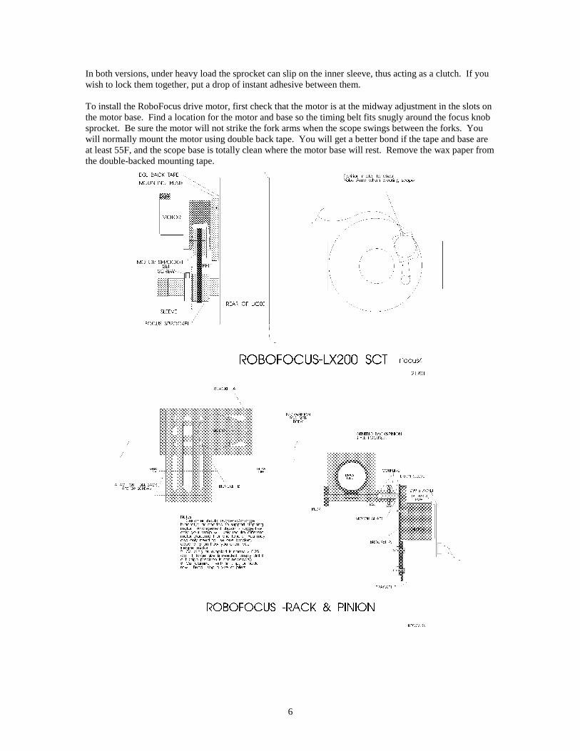
In both versions, under heavy load the sprocket can slip on the inner sleeve, thus acting as a clutch. If you
wish to lock them together, put a drop of instant adhesive between them.
To install the RoboFocus drive motor, first check that the motor is at the midway adjustment in the slots on
the motor base. Find a location for the motor and base so the timing belt fits snugly around the focus knob
sprocket. Be sure the motor will not strike the fork arms when the scope swings between the forks. You
will normally mount the motor using double back tape. You will get a better bond if the tape and base are
at least 55F, and the scope base is totally clean where the motor base will rest. Remove the wax paper from
the double-backed mounting tape.
7
8
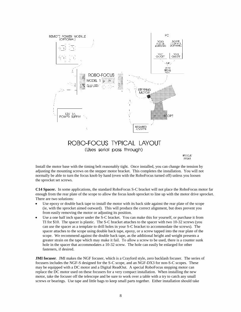
Install the motor base with the timing belt reasonably tight. Once installed, you can change the tension by
adjusting the mounting screws on the stepper motor bracket. This completes the installation. You will not
normally be able to turn the focus knob by hand (even with the RoboFocus turned off) unless you loosen
the sprocket set screws.
C14 Spacer. In some applications, the standard RoboFocus S-C bracket will not place the RoboFocus motor far
enough from the rear plate of the scope to allow the focus knob sprocket to line up with the motor drive sprocket.
There are two solutions:
Use epoxy or double back tape to install the motor with its back side against the rear plate of the scope
(ie, with the sprocket aimed outward). This will produce the correct alignment, but does prevent you
from easily removing the motor or adjusting its position.
Use a one half inch spacer under the S-C bracket. You can make this for yourself, or purchase it from
TI for $10. The spacer is plastic. The S-C bracket attaches to the spacer with two 10-32 screws (you
can use the spacer as a template to drill holes in your S-C bracket to accommodate the screws). The
spacer attaches to the scope using double back tape, epoxy, or a screw tapped into the rear plate of the
scope. We recommend against the double back tape, as the additional height and weight presents a
greater strain on the tape which may make it fail. To allow a screw to be used, there is a counter sunk
hole in the spacer that accommodates a 10-32 screw. The hole can easily be enlarged for other
fasteners, if desired.
JMI focuser. JMI makes the NGF focuser, which is a Crayford style, zero backlash focuser. The series of
focusers includes the NGF-S designed for the S-C scope, and an NGF-DX3 for non-S-C scopes. These
may be equipped with a DC motor and a Digital ReadOut. A special RoboFocus stepping motor can
replace the DC motor used on these focusers for a very compact installation. When installing the new
motor, take the focuser off the telescope and be sure to work over a table with a try to catch any small
screws or bearings. Use tape and little bags to keep small parts together. Either installation should take
9
about ten minutes. When complete, adjust the bearing tensions so that the focus tube will hold about 5lb
without slipping.
NGF-S.
Use 3/32 allen wrench to remove the pair of set screws holding the jack shaft and bearing (visible in a
slot on the side of the focuser). Working over the tray, turn the focuser on its side and remove the jack
shaft and bearing.
Use 1/16 allen wrench to loosen (don’t remove) the set screw holding the focus shaft far bearing at the
end away from the motor
Working over the tray, remove the screw holding the motor and remove the motor and shaft from the
focuser. An inboard bearing next to the motor will come out with it, and unless you hold it in, the far
bearing will likely fall out. Don’t lose it!
Install the new motor/shaft with its new inboard bearing. The bearing should fit into its seat in the
focuser. Install the motor mounting screw lightly.
Install the old far bearing onto the new shaft and tighten its set screw
Drop the jack shaft and bearing into its slot, install the two set screws to equal depths gently tight
Finish tightening the motor screw.
Adjust focuser tension with the jack shaft bearing set screws
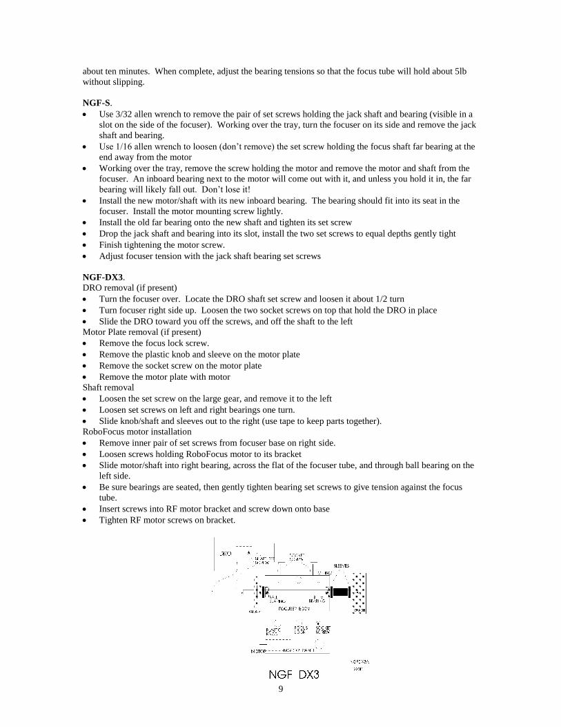
NGF-DX3.
DRO removal (if present)
Turn the focuser over. Locate the DRO shaft set screw and loosen it about 1/2 turn
Turn focuser right side up. Loosen the two socket screws on top that hold the DRO in place
Slide the DRO toward you off the screws, and off the shaft to the left
Motor Plate removal (if present)
Remove the focus lock screw.
Remove the plastic knob and sleeve on the motor plate
Remove the socket screw on the motor plate
Remove the motor plate with motor
Shaft removal
Loosen the set screw on the large gear, and remove it to the left
Loosen set screws on left and right bearings one turn.
Slide knob/shaft and sleeves out to the right (use tape to keep parts together).
RoboFocus motor installation
Remove inner pair of set screws from focuser base on right side.
Loosen screws holding RoboFocus motor to its bracket
Slide motor/shaft into right bearing, across the flat of the focuser tube, and through ball bearing on the
left side.
Be sure bearings are seated, then gently tighten bearing set screws to give tension against the focus
tube.
Insert screws into RF motor bracket and screw down onto base
Tighten RF motor screws on bracket.
10
RoboFocus Electrical
The RoboFocus control box has five electrical connections. First, on the left end of the box:
―+12V‖ — 12VDC (positive) input from the 120VAC power supply included
―REMPOW MOD‖ — Remote Power Module connection. RoboFocus provides four control channels
for the user for the optional RoboFocus Remote Power Module. You can remotely power your scope,
CCD, dew heaters, etc.
On the right end of the box:
―PC‖ — This is your RS232 connection from the computer. We include a 6-conductor telephone cable
(a 12ft length) and an adapter for the PC jack (PC1). DO NOT USE commercial 6-pin cables unless
you have verified that they are suitable. See appendix for details on making your own cable. Ideally,
the RoboFocus will have its own RS232 serial port on the PC; however, the RoboFocus can also
operate on the same port as the telescope control software (see below).
―SCOPE/HAND‖ — If you wish to operate the RoboFocus on the same serial port as your telescope,
connect the scope to this jack through the proper adapter. See discussion below for details. This jack
is also used for the optional RoboFocus hand control (hand control and scope connection cannot be
used at the same time unless you have an adapter from us). CAUTION: do NOT connect your scope
directly to this jack or you may damage it.
―STEP MOTOR‖ — The stepping motor connects to the DB9 connector using the 9-pin cable (an 8
foot length is provided).
The control box is usually mounted on the telescope pier where the wiring is convenient. In general, we
recommend mounting the control box vertically with the power switch DOWN. The reason is that the
internal temperature sensor will then be downward, so that the temperature readings will be less affected by
the internal heating in the controller.
Serial Pass Through
The Scope/Hand jack requires more discussion. As noted, one can connect the RoboFocus to its own serial
port (you will need to use the PC1 PC adapter to go from the DB-9 connector on the PC into the telephone
type cable used in the RoboFocus).
However, if you are limited in the number of serial ports available, you have a choice of adding serial ports
to your PC (see appendix) or you can use the RoboFocus ―Scope‖ jack. The RoboFocus is wired to allow it
to be on the same RS232 circuit as other devices, such as the telescope. The signals for both the
RoboFocus and the scope pass into the RoboFocus on the same cable. The RoboFocus will respond only to
its own signals. The scope signals will pass through the RoboFocus to the scope, and the scope responses
will pass back through the RoboFocus to the computer.
Because the wiring of each type of scope is different, you MUST use the proper adapter between the
RoboFocus ―SCOPE‖ jack and the scope itself: NEVER connect the scope directly to the RoboFocus
controller. If the proper adapter was not included in your RoboFocus package, please call us to obtain one.
If you intend to connect to an LX200, and you already have Digital Dome Works, you can use the LX200
adapter that came with DDW.
Unfortunately, your computer will not allow two different programs (e.g., focuser and scope control) to
connect to the same serial port at the same time. Therefore, to take full advantage of this feature, the scope
and focuser software must be in the same program. Although we expect such software soon, it is not yet
available.
However, you can take partial advantage of this design and still avoid adding serial ports. To do this,
connect your scope (or other RS232 device) to the Scope input, then alternately connect the software
programs to the serial port. For example, in the scope control program, open the port to the scope, aim the
11
scope at a star, then close the port (while leaving the program running). Switch to the focuser control
program, open the COM connection, thus connecting the port to the RoboFocus, perform your focusing,
then close the connection to the port. You can then switch back to the scope program, open the port once
again for telescope control. These steps are easy to do in Windows. During this process, you have left all
wiring in place.
This method will operate with most scopes and software. However, it is possible that some scopes or
software will not tolerate the focuser commands and data that are on the same line. Failures will generally
show up as software lockup or errors. Because of the coding protections, you will not have inadvertent
movements. If you do run into these problems, you will need to use a separate port for the RoboFocus or
change the software you use for scope control. Our tests with RoboFocus using the same Com port with
TheSky and LX200 or the AP GTO scopes show no compatibility problems.
Remote Power Module
The optional Remote Power Module allows you to control four outlets independently from your computer
(or from the RoboFocus itself). If you wish, you can plug multi-outlet strips into the outlets so that you can
control more items. Limit the total load to 10A maximum
The Remote Power Module plugs into a wall outlet for its 120VAC supply. Use the six conductor
telephone type cable provided to connect the Module to the RoboFocus (do NOT use commercial cables).
Hand Control
The hand control is an optional two button control that is useful if you do frequent manual focusing (i.e.,
focusing while looking through the eyepiece). The hand control plugs into the ―scope‖ jack. Depending on
the pass-through adapter you are using, this may require temporary disconnection of the cable from
RoboFocus to the scope (this is not a problem, as the two functions are not used at the same time). The
hand control also has a pilot light that mimics the light on the RoboFocus control unit. All directions given
for the control unit push buttons also apply to the hand control.
Remote Temperature Sensor
RoboFocus has a temperature sensor built into the control box (on the underside of the printed circuit
board). In some cases, the user may wish to use a remote sensor, ie., attached to the telescope tube. This is
available as an option with a cable that plugs into the motor cable connector. If using the remote sensor,
the internal sensor must be disconnected inside the controller. Instructions with the remote sensor will
provide details.
12
3. Operation of RoboFocus
Introduction
The operation of the RoboFocus begins with a brief initial check in which you will assure that the direction
of the buttons is correct (―the IN button yields ―IN‖ movement). You will also check the operation of the
clutch (Rack and Pinion models)
You can then operate the focuser manually (locally) or via the RFCP running on the PC (remotely).
Because the remote operation is the more complete, we will discuss that first. In the meantime, however,
don’t be afraid to push the buttons to move the focuser!
Initial Check – Motion Direction and Clutch
WARNING: Check that you have loosened any focus locks on your focuser! You may want to remove the
focus lock so that you don’t accidentally use it in the future as the RoboFocus motor will hold focus
position.
Direction Convention. In/Out directions are obvious for a R&P focuser. For a S-C scope, we use
CW/CCW for the knob as the corresponding directions. You can operate with reversed directions;
however, using the standard avoids confusion.
Direction. To check the RoboFocus direction, push the OUT button. You will notice that when you push
the button, the stepper executes one step (with a beep), waits for 1/2 second, then starts running at full
speed. This system allows making small focus changes when operating manually. If the RoboFocus OUT
button moves the focuser out (CCW on an SC scope), the direction is OK. If the direction is wrong, turn
off the RoboFocus. After about ten seconds, turn on the RoboFocus while pressing the OUT button. As
the RoboFocus powers up, it will sense the OUT button, will reverse itself (switching from inward to
outward), and will record the new button direction. After several seconds the RoboFocus will start running
outward and you can release the button. The RoboFocus will remember this direction information for
future sessions.
Clutch. You should now check the clutch setting (Rack & Pinion models only). The clutch screws should
be set fairly tight; i.e. you want to be sure the RoboFocus stepping motor does not slip under any normal
operation. The best test is to load the focuser and orient the scope upwards so that the maximum
gravitational force is put on the stepping motor. Then operate the IN button while watching for focuser
movement. Adjust the clutch screws as necessary to avoid slippage.
When you first apply power and turn on your RoboFocus, it has settings for its current position and the
length of travel available to it that are left over from factory testing. Before accurate operation can be done,
you will need to calibrate the length of travel of your focuser. You can run RoboFocus without this
calibration, but you will not have accurate absolute positioning.
Local Operation.
When you are in the observatory and want to operate the focuser, you may use the RoboFocus buttons to
provide local (manual) operation. When using the buttons, you will notice that the stepper steps once
(with a beep) and then switches to high speed (this helps in making small focus changes). A few
comments:
If you run all the way in, and then keep going, the stepper will continue to run (with the clutch
slipping), and will continue to reset its current position to 1.
If you run all the way out, and then keep going, the stepper will continue to run, and will continue to
reset its current position to a new maximum travel
13
If you want to retrain, you can do so at any time. However, the usual problem is that you removed or
turned off the RoboFocus and then manually adjusted the focuser. Of course, this causes loss of
information on the current position. In this case, although you can retrain, it is often sufficient to
simply reset the position to approximately the correct value using your computer (see below).
If you want to focus with your manual R&P control knob, turn off the RoboFocus. This will release
the magnetic brake that prevents motion, though the gears will make motion stiff unless you release the
clutch screws. . If you use manual knob focus you will, of course, lose accurate position data.
Manual button use preserves position data.
Of course, the backlash compensation does not function in local button operation because the user
determines the amount of movement. In local operation, you can also use the manual buttons to turn the
Remote Power Modules on or off, and you can set values for the duty cycle, steprate, and stepsize. How to
do this is discussed below.
We suggest that you hook up and test-run the focuser in and out with the buttons. If the focuser is too slow
or fast, you may want to change the speed. If the position count is too small or too large as you go from
one end of travel to another, you may want to change the number of microsteps per count. While you can
make these changes using the manual menu buttons, it is much easier to use the RFCP computer program.
You can always come back later to calibrate the length of travel.
Remote Operation: Use of RoboFocus Control Program (RFCP)
You can leave the RFCP running or not, as you wish. Even if RFCP is turned off, if the RoboFocus
controller is powered, it will hold the focus setting as well as any remote control power settings. You may
want to leave the RFCP program running, but switch between RoboFocus and a scope program (to avoid
software interference) using the COM connect/terminate settings.
Note: Because the RoboFocus requires time to process commands, carry out the instruction, and return
data, you should avoid rapid button pushing. That is, give the RoboFocus a few seconds to respond before
repeating a command or sending a new one. Also, on some computers with some color settings, running
RFCP may change the color of other displays. Please contact us if this causes you a problem.
Main Control Screen
The control screen or window provides the basic movement controls and access to additional screens for
other functions. The screen is small so that you can tuck it out of the way on your desktop. We will now
briefly describe the various controls on the screen. Several are discussed in more detail below.
Title Bar. The title bar will show the version number of the RFCP and the version number of the
controller, if connected.
COM#. This button toggles the chosen COM port connection. When the button is gray, the COM port is
closed (inoperative). Assuming you have made the proper settings (see configuration screen below), when
you click COM# the RFCP will connect to the controller. When the RFCP has completed the process of
connection, including getting information from the controller, then COM# will turn green showing that the
connection is made. You cut off the connection by clicking on the green COM#. The # sign will show the
chosen COM port number.
CONFIGuration. This button brings up the configuration screen (see below).
TempComp. This button brings up the temperature compensation screen from which you can train or
operate the temperature compensation (see below).
Temperature. This is a passive display of the temperature. The display automatically updates at the rate
set by the entries in the temperature compensation screen (though independent of whether temperature
compensation is actually turned on), or when a refresh or other action is made. The units (Raw, F, or C)
14
and calibration are selected in the temperature compensation screen. Note that Celsius and Fahrenheit
cannot be selected until temperature calibration is performed.
Help. This button brings up the Help/About screen. This screen shows details of the RFCP (date, version,
etc.). The screen also has the Help button. When clicked, the Help button activates a copy of the WORD
viewer, which in turn opens a copy of the instruction manual. Using the viewer, you can read any portion
of the manual, or print it out.
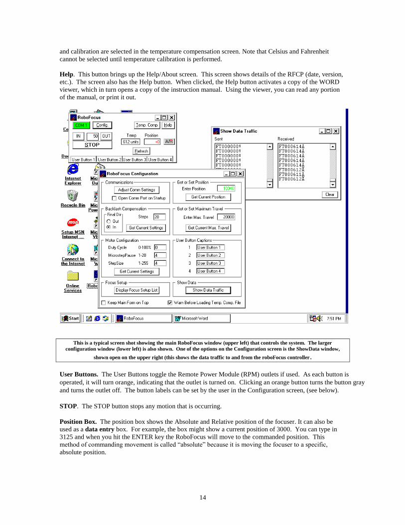
This is a typical screen shot showing the main RoboFocus window (upper left) that controls the system. The larger
configuration window (lower left) is also shown. One of the options on the Configuration screen is the ShowData window,
shown open on the upper right (this shows the data traffic to and from the roboFocus controller.
User Buttons. The User Buttons toggle the Remote Power Module (RPM) outlets if used. As each button is
operated, it will turn orange, indicating that the outlet is turned on. Clicking an orange button turns the button gray
and turns the outlet off. The button labels can be set by the user in the Configuration screen, (see below).
STOP. The STOP button stops any motion that is occurring.
Position Box. The position box shows the Absolute and Relative position of the focuser. It can also be
used as a data entry box. For example, the box might show a current position of 3000. You can type in
3125 and when you hit the ENTER key the RoboFocus will move to the commanded position. This
method of commanding movement is called ―absolute‖ because it is moving the focuser to a specific,
absolute position.
15
IN/OUT. On the left is a box into which you can type your intended relative motion, e.g., 50 steps. Now
you can click IN or OUT and the focuser will move as directed. This is very useful in fine focusing.
Absolute/Relative (A/R). To the right of the position window is a button labeled A/R (the R is red). This
button is a toggle. That is, if the absolute position is being displayed, e.g. a black 3000, and the button is
pressed, a +/- red relative value will be shown, e.g. a + red ―0‖ zero. Now if you move the focuser using
the in/out buttons you will see the motion relative to the setting present when you toggled to the Relative
mode. You return to absolute by toggling A/R again. This is very useful for keeping track of the net
movement in and out during focusing!
Focuser Movement. You can command motions of the focuser in one of two ways:
Position Box Enter the desired position into the position box and hit enter and the focuser will move
to the desired location.
In/Out Controls. You can enter the number of steps to change in the IN/OUT box, then click IN or
OUT and the focuser will move accordingly.
Refresh. When you click this button, RFCP queries the controller to get the current position and
temperature as well as other configuration data. The current position is displayed in the window to the
right. This position is updated upon a refresh, and at the conclusion of any move.
Configuration Screen
This screen is used to read or set the configuration items of the RoboFocus control program and controller.
Communications. The first time you use the RoboFocus, you will need to select the CONFIGuration
menu item. Then select Adjust CommSettings. This will show a screen with various communication
parameters. One of these is the COM port. You will choose the serial COM port you intend to use. You
will usually be using COM port numbered one through four. The rest of the settings are 9600 baud, 8 bit, 1
stop bit. Note that you can connect/disconnect the COM port without turning the program off. The COM
port will close when the program is closed.
You can now make or break your COM connection from the RFCP by clicking on the Open/Close COM
button on the main window. When you OPEN the COM port, you automatically issue commands to refresh
the RFCP data (version number, current position, and remote power module settings.)
At this point, if you have established communication with the RoboFocus, you will see the current position
displayed. The current position updates itself only when you first turn on or when you do a computer
directed focus move, or when you click the Refresh box to query the RoboFocus and renew the reading.
The RFCP does not poll the RoboFocus controller on a regular basis.
Backlash. Backlash is the ―mechanical lag‖ in the mechanical movement of the focuser itself. That is,
depending on the loading of the focuser and whether you are moving in or out, after moving in one
direction, you may have to move for a substantial distance before actual reverse focus movement begins.
To compensate for this, the RoboFocus can operate the commanded distance plus extra steps for
compensation, then reverses the extra steps so that all moves, no matter what the direction, are finished
with motion in the same direction. Factory default is compensation set for inbound, 20 steps. This
configuration control allows you to turn compensation to a value of 0-64,000 for IN bound (all motions
FINISH with movement in the INbound direction) or OUTbound.
The backlash compensation need not be set precisely—all that is needed is to take up the focuser system
slack in the direction of concern. Experience shows that with a stepsize of four, approximately 10-20 steps
of the RoboFocus are usually enough to accomplish this on a R&P focuser, while the LX200 may require
100 or more steps to accomplish the backlash correction.
16
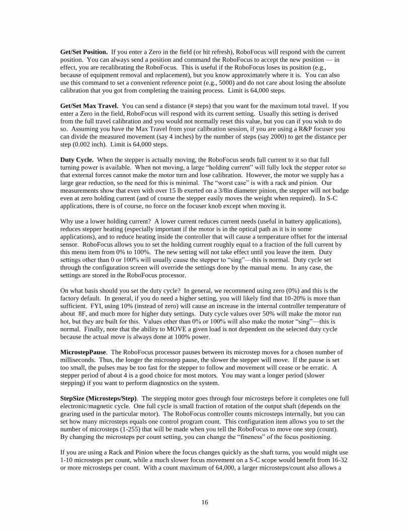
Get/Set Position. If you enter a Zero in the field (or hit refresh), RoboFocus will respond with the current
position. You can always send a position and command the RoboFocus to accept the new position — in
effect, you are recalibrating the RoboFocus. This is useful if the RoboFocus loses its position (e.g.,
because of equipment removal and replacement), but you know approximately where it is. You can also
use this command to set a convenient reference point (e.g., 5000) and do not care about losing the absolute
calibration that you got from completing the training process. Limit is 64,000 steps.
Get/Set Max Travel. You can send a distance (# steps) that you want for the maximum total travel. If you
enter a Zero in the field, RoboFocus will respond with its current setting. Usually this setting is derived
from the full travel calibration and you would not normally reset this value, but you can if you wish to do
so. Assuming you have the Max Travel from your calibration session, if you are using a R&P focuser you
can divide the measured movement (say 4 inches) by the number of steps (say 2000) to get the distance per
step (0.002 inch). Limit is 64,000 steps.
Duty Cycle. When the stepper is actually moving, the RoboFocus sends full current to it so that full
turning power is available. When not moving, a large ―holding current‖ will fully lock the stepper rotor so
that external forces cannot make the motor turn and lose calibration. However, the motor we supply has a
large gear reduction, so the need for this is minimal. The ―worst case‖ is with a rack and pinion. Our
measurements show that even with over 15 lb exerted on a 3/8in diameter pinion, the stepper will not budge
even at zero holding current (and of course the stepper easily moves the weight when required). In S-C
applications, there is of course, no force on the focuser knob except when moving it.
Why use a lower holding current? A lower current reduces current needs (useful in battery applications),
reduces stepper heating (especially important if the motor is in the optical path as it is in some
applications), and to reduce heating inside the controller that will cause a temperature offset for the internal
sensor. RoboFocus allows you to set the holding current roughly equal to a fraction of the full current by
this menu item from 0% to 100%. The new setting will not take effect until you leave the item. Duty
settings other than 0 or 100% will usually cause the stepper to ―sing‖—this is normal. Duty cycle set
through the configuration screen will override the settings done by the manual menu. In any case, the
settings are stored in the RoboFocus processor.
On what basis should you set the duty cycle? In general, we recommend using zero (0%) and this is the
factory default. In general, if you do need a higher setting, you will likely find that 10-20% is more than
sufficient. FYI, using 10% (instead of zero) will cause an increase in the internal controller temperature of
about 8F, and much more for higher duty settings. Duty cycle values over 50% will make the motor run
hot, but they are built for this. Values other than 0% or 100% will also make the motor ―sing‖—this is
normal. Finally, note that the ability to MOVE a given load is not dependent on the selected duty cycle
because the actual move is always done at 100% power.
MicrostepPause. The RoboFocus processor pauses between its microstep moves for a chosen number of
milliseconds. Thus, the longer the microstep pause, the slower the stepper will move. If the pause is set
too small, the pulses may be too fast for the stepper to follow and movement will cease or be erratic. A
stepper period of about 4 is a good choice for most motors. You may want a longer period (slower
stepping) if you want to perform diagnostics on the system.
StepSize (Microsteps/Step). The stepping motor goes through four microsteps before it completes one full
electronic/magnetic cycle. One full cycle is small fraction of rotation of the output shaft (depends on the
gearing used in the particular motor). The RoboFocus controller counts microsteps internally, but you can
set how many microsteps equals one control program count. This configuration item allows you to set the
number of microsteps (1-255) that will be made when you tell the RoboFocus to move one step (count).
By changing the microsteps per count setting, you can change the ―fineness‖ of the focus positioning.
If you are using a Rack and Pinion where the focus changes quickly as the shaft turns, you would might use
1-10 microsteps per count, while a much slower focus movement on a S-C scope would benefit from 16-32
or more microsteps per count. With a count maximum of 64,000, a larger microsteps/count also allows a
17
longer travel without resetting the position count. If you find that you need a finer focus adjustment,
simply decrease the number of microsteps per count.
User Button Captions. This is where you insert labels for your four Remote Power Module channels.
These labels then appear on the main screen of RFCP.
Show Data. The Show Data button brings up a separate screen that shows the serial communication out to
the RoboFocus and back to the PC. This is useful in diagnosing problems in the system.
Focus Setup. The Focus Setup button brings up a screen in which you can record the name or description
of up to 20 different optical setups, and for each one identify the ―correct‖ focus. Thus, if you change
optical setups, or use the RoboFocus control program for more than one scope, you can easily run the
focuser to the desired position (and then refine the focus, if needed).
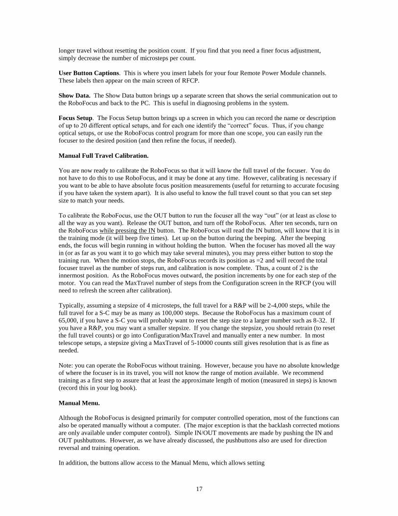
Manual Full Travel Calibration.
You are now ready to calibrate the RoboFocus so that it will know the full travel of the focuser. You do
not have to do this to use RoboFocus, and it may be done at any time. However, calibrating is necessary if
you want to be able to have absolute focus position measurements (useful for returning to accurate focusing
if you have taken the system apart). It is also useful to know the full travel count so that you can set step
size to match your needs.
To calibrate the RoboFocus, use the OUT button to run the focuser all the way ―out‖ (or at least as close to
all the way as you want). Release the OUT button, and turn off the RoboFocus. After ten seconds, turn on
the RoboFocus while pressing the IN button. The RoboFocus will read the IN button, will know that it is in
the training mode (it will beep five times). Let up on the button during the beeping. After the beeping
ends, the focus will begin running in without holding the button. When the focuser has moved all the way
in (or as far as you want it to go which may take several minutes), you may press either button to stop the
training run. When the motion stops, the RoboFocus records its position as =2 and will record the total
focuser travel as the number of steps run, and calibration is now complete. Thus, a count of 2 is the
innermost position. As the RoboFocus moves outward, the position increments by one for each step of the
motor. You can read the MaxTravel number of steps from the Configuration screen in the RFCP (you will
need to refresh the screen after calibration).
Typically, assuming a stepsize of 4 microsteps, the full travel for a R&P will be 2-4,000 steps, while the
full travel for a S-C may be as many as 100,000 steps. Because the RoboFocus has a maximum count of
65,000, if you have a S-C you will probably want to reset the step size to a larger number such as 8-32. If
you have a R&P, you may want a smaller stepsize. If you change the stepsize, you should retrain (to reset
the full travel counts) or go into Configuration/MaxTravel and manually enter a new number. In most
telescope setups, a stepsize giving a MaxTravel of 5-10000 counts still gives resolution that is as fine as
needed.
Note: you can operate the RoboFocus without training. However, because you have no absolute knowledge
of where the focuser is in its travel, you will not know the range of motion available. We recommend
training as a first step to assure that at least the approximate length of motion (measured in steps) is known
(record this in your log book).
Manual Menu.
Although the RoboFocus is designed primarily for computer controlled operation, most of the functions can
also be operated manually without a computer. (The major exception is that the backlash corrected motions
are only available under computer control). Simple IN/OUT movements are made by pushing the IN and
OUT pushbuttons. However, as we have already discussed, the pushbuttons also are used for direction
reversal and training operation.
In addition, the buttons allow access to the Manual Menu, which allows setting
18
Remote Power channels on/off
Duty cycle of stepping motor when at rest (power consumption)
Step Rate of motor when running (motor speed), StepSize, and Microsteps/count (coarseness of
movement)
StepSize (number of microsteps per count)
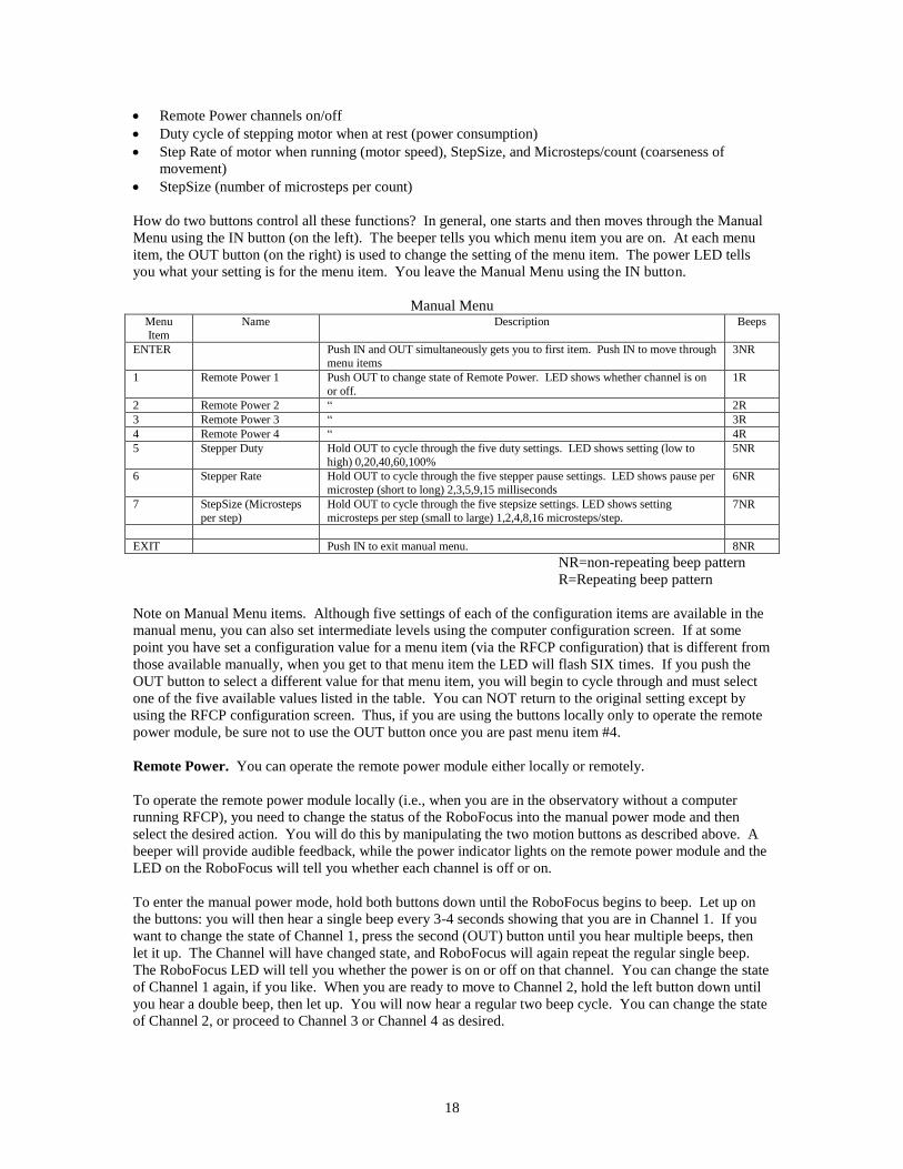
How do two buttons control all these functions? In general, one starts and then moves through the Manual
Menu using the IN button (on the left). The beeper tells you which menu item you are on. At each menu
item, the OUT button (on the right) is used to change the setting of the menu item. The power LED tells
you what your setting is for the menu item. You leave the Manual Menu using the IN button.
Manual Menu Menu
Item
Name Description Beeps
ENTER Push IN and OUT simultaneously gets you to first item. Push IN to move through
menu items
3NR
1 Remote Power 1 Push OUT to change state of Remote Power. LED shows whether channel is on
or off.
1R
2 Remote Power 2 ― 2R
3 Remote Power 3 ― 3R
4 Remote Power 4 ― 4R
5 Stepper Duty Hold OUT to cycle through the five duty settings. LED shows setting (low to
high) 0,20,40,60,100%
5NR
6 Stepper Rate Hold OUT to cycle through the five stepper pause settings. LED shows pause per
microstep (short to long) 2,3,5,9,15 milliseconds
6NR
7 StepSize (Microsteps
per step)
Hold OUT to cycle through the five stepsize settings. LED shows setting
microsteps per step (small to large) 1,2,4,8,16 microsteps/step.
7NR
EXIT Push IN to exit manual menu. 8NR
NR=non-repeating beep pattern
R=Repeating beep pattern
Note on Manual Menu items. Although five settings of each of the configuration items are available in the
manual menu, you can also set intermediate levels using the computer configuration screen. If at some
point you have set a configuration value for a menu item (via the RFCP configuration) that is different from
those available manually, when you get to that menu item the LED will flash SIX times. If you push the
OUT button to select a different value for that menu item, you will begin to cycle through and must select
one of the five available values listed in the table. You can NOT return to the original setting except by
using the RFCP configuration screen. Thus, if you are using the buttons locally only to operate the remote
power module, be sure not to use the OUT button once you are past menu item #4.
Remote Power. You can operate the remote power module either locally or remotely.
To operate the remote power module locally (i.e., when you are in the observatory without a computer
running RFCP), you need to change the status of the RoboFocus into the manual power mode and then
select the desired action. You will do this by manipulating the two motion buttons as described above. A
beeper will provide audible feedback, while the power indicator lights on the remote power module and the
LED on the RoboFocus will tell you whether each channel is off or on.
To enter the manual power mode, hold both buttons down until the RoboFocus begins to beep. Let up on
the buttons: you will then hear a single beep every 3-4 seconds showing that you are in Channel 1. If you
want to change the state of Channel 1, press the second (OUT) button until you hear multiple beeps, then
let it up. The Channel will have changed state, and RoboFocus will again repeat the regular single beep.
The RoboFocus LED will tell you whether the power is on or off on that channel. You can change the state
of Channel 1 again, if you like. When you are ready to move to Channel 2, hold the left button down until
you hear a double beep, then let up. You will now hear a regular two beep cycle. You can change the state
of Channel 2, or proceed to Channel 3 or Channel 4 as desired.
19
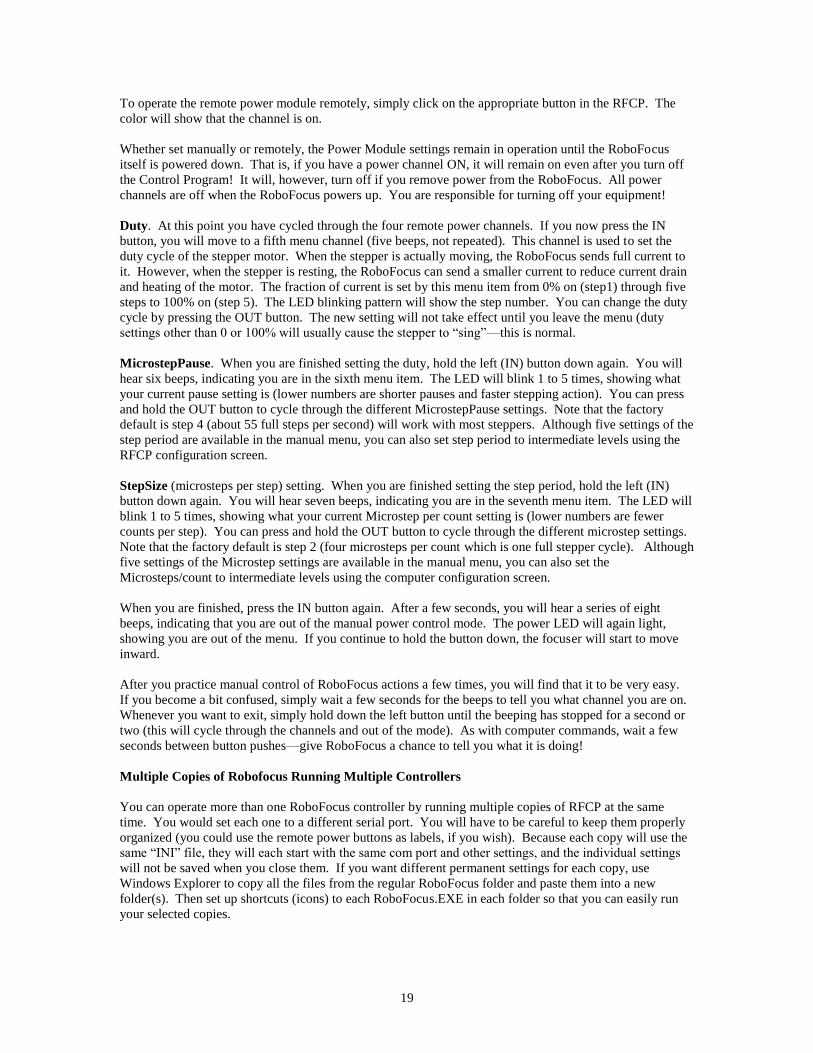
To operate the remote power module remotely, simply click on the appropriate button in the RFCP. The
color will show that the channel is on.
Whether set manually or remotely, the Power Module settings remain in operation until the RoboFocus
itself is powered down. That is, if you have a power channel ON, it will remain on even after you turn off
the Control Program! It will, however, turn off if you remove power from the RoboFocus. All power
channels are off when the RoboFocus powers up. You are responsible for turning off your equipment!
Duty. At this point you have cycled through the four remote power channels. If you now press the IN
button, you will move to a fifth menu channel (five beeps, not repeated). This channel is used to set the
duty cycle of the stepper motor. When the stepper is actually moving, the RoboFocus sends full current to
it. However, when the stepper is resting, the RoboFocus can send a smaller current to reduce current drain
and heating of the motor. The fraction of current is set by this menu item from 0% on (step1) through five
steps to 100% on (step 5). The LED blinking pattern will show the step number. You can change the duty
cycle by pressing the OUT button. The new setting will not take effect until you leave the menu (duty
settings other than 0 or 100% will usually cause the stepper to ―sing‖—this is normal.
MicrostepPause. When you are finished setting the duty, hold the left (IN) button down again. You will
hear six beeps, indicating you are in the sixth menu item. The LED will blink 1 to 5 times, showing what
your current pause setting is (lower numbers are shorter pauses and faster stepping action). You can press
and hold the OUT button to cycle through the different MicrostepPause settings. Note that the factory
default is step 4 (about 55 full steps per second) will work with most steppers. Although five settings of the
step period are available in the manual menu, you can also set step period to intermediate levels using the
RFCP configuration screen.
StepSize (microsteps per step) setting. When you are finished setting the step period, hold the left (IN)
button down again. You will hear seven beeps, indicating you are in the seventh menu item. The LED will
blink 1 to 5 times, showing what your current Microstep per count setting is (lower numbers are fewer
counts per step). You can press and hold the OUT button to cycle through the different microstep settings.
Note that the factory default is step 2 (four microsteps per count which is one full stepper cycle). Although
five settings of the Microstep settings are available in the manual menu, you can also set the
Microsteps/count to intermediate levels using the computer configuration screen.
When you are finished, press the IN button again. After a few seconds, you will hear a series of eight
beeps, indicating that you are out of the manual power control mode. The power LED will again light,
showing you are out of the menu. If you continue to hold the button down, the focuser will start to move
inward.
After you practice manual control of RoboFocus actions a few times, you will find that it to be very easy.
If you become a bit confused, simply wait a few seconds for the beeps to tell you what channel you are on.
Whenever you want to exit, simply hold down the left button until the beeping has stopped for a second or
two (this will cycle through the channels and out of the mode). As with computer commands, wait a few
seconds between button pushes—give RoboFocus a chance to tell you what it is doing!
Multiple Copies of Robofocus Running Multiple Controllers
You can operate more than one RoboFocus controller by running multiple copies of RFCP at the same
time. You would set each one to a different serial port. You will have to be careful to keep them properly
organized (you could use the remote power buttons as labels, if you wish). Because each copy will use the
same ―INI‖ file, they will each start with the same com port and other settings, and the individual settings
will not be saved when you close them. If you want different permanent settings for each copy, use
Windows Explorer to copy all the files from the regular RoboFocus folder and paste them into a new
folder(s). Then set up shortcuts (icons) to each RoboFocus.EXE in each folder so that you can easily run
your selected copies.
20
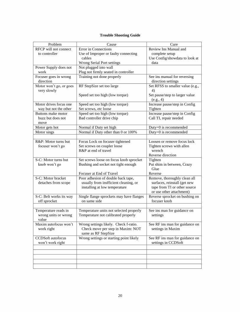
Trouble Shooting Guide
Problem Cause Cure
RFCP will not connect
to controller
Error in Connections
Use of Improper or faulty connecting
cables
Wrong Serial Port settings
Review Ins Manual and
complete setup
Use Config/showdata to look at
data
Power Supply does not
work
Not plugged into wall
Plug not firmly seated in controller
Focuser goes in wrong
direction
Training not done properly See ins manual for reversing
direction settings
Motor won’t go, or goes
very slowly
RF StepSize set too large
Speed set too high (low torque)
Set RFSS to smaller value (e.g.,
4)
Set pause/step to larger value
(e.g., 4)
Motor drives focus one
way but not the other
Speed set too high (low torque)
Set screws, etc loose
Increase pause/step in Config
Tighten
Buttons make motor
buzz but does not
move
Speed set too high (low torque)
Bad controller drive chip
Increase pause/step in Config
Call TI, repair needed
Motor gets hot Normal if Duty set high Duty=0 is recommended
Motor sings Normal if Duty other than 0 or 100% Duty=0 is recommended
R&P: Motor turns but
focuser won’t go
Focus Lock on focuser tightened
Set screws on coupler loose
R&P at end of travel
Loosen or remove focus lock
Tighten screws with allen
wrench
Reverse direction
S-C: Motor turns but
knob won’t go
Set screws loose on focus knob sprocket
Bushing and socket not tight enough
Focuser at End of Travel
Tighten
Put shim in between, Crazy
Glue
Reverse
S-C: Motor bracket
detaches from scope
Poor adhesion of double back tape,
usually from insfficient cleaning, or
installing at low temperature
Remove, thoroughly clean all
surfaces, reinstall (get new
tape from TI or other source
or use other attachment)
S-C: Belt works its way
off sprocket
Single flange sprockets may have flanges
on same side
Reverse sprocket on bushing on
focuser knob
Temperature reads in
wrong units or wrong
value
Temperature units not selected properly
Temperature not calibrated properly
See ins man for guidance on
settings
Maxim autofocus won’t
work right
Wrong settings likely. Check f-ratio.
Check move per step in Maxim: NOT
same as RF StepSize
See RF ins man for guidance on
settings in Maxim
CCDSoft autofocus
won’t work right
Wrong settings or starting point likely See RF ins man for guidance on
settings in CCDSoft
21
4. Temperature Compensation
Introduction
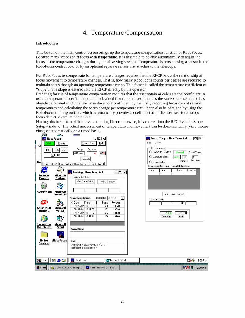
This button on the main control screen brings up the temperature compensation function of RoboFocus.
Because many scopes shift focus with temperature, it is desirable to be able automatically to adjust the
focus as the temperature changes during the observing session. Temperature is sensed using a sensor in the
RoboFocus control box, or by an optional separate sensor that attaches to the telescope.
For RoboFocus to compensate for temperature changes requires that the RFCP know the relationship of
focus movement to temperature changes. That is, how many RoboFocus counts per degree are required to
maintain focus through an operating temperature range. This factor is called the temperature coefficient or
―slope‖. The slope is entered into the RFCP directly by the operator.
Preparing for use of temperature compensation requires that the user obtain or calculate the coefficient. A
usable temperature coefficient could be obtained from another user that has the same scope setup and has
already calculated it. Or the user may develop a coefficient by manually recording focus data at several
temperatures and calculating the focus change per temperature unit. It can also be obtained by using the
RoboFocus training routine, which automatically provides a coefficient after the user has stored scope
focus data at several temperatures.
Having obtained the coefficient via a training file or otherwise, it is entered into the RFCP via the Slope
Setup window. The actual measurement of temperature and movement can be done manually (via a mouse
click) or automatically on a timed basis.
22
Note: temperature is measured using the built in temperature sensor in the RoboFocus controller. The
temperature readings are in raw temperature counts (the counts are close to twice the absolute temperature
in deg. Kelvin, with 32F=0C=273K=546 counts approximately), or in F, or C.
We have supplied a temperature compensation dataset that was taken with an 8in. f/10 LX200 under test
conditions. Your setup will almost surely have different values for all the data; however, it will give you
some idea of how the data might look. As noted below, you can inspect the file using RFCP, Notepad, or
Excel. Except to experiment, do NOT use this file to operate your telescope as it will surely produce
incorrect results.
Note: When using the internal temperature sensor either in training or in operation, we recommend setting
the duty cycle (configuration screen) to zero or 10% to reduce heating of the sensor (see Duty Cycle
discussion in previous chapter). The controller should also be mounted vertically with the power switch
down to reduce heating of the sensor by the electronics. See the discussion below.
Manual Temperature Coefficient
As noted above, you can manually enter a temperature coefficient and then begin compensation. But how
do you know what to enter? There are several ways:
You might know other people with the same telescope who have already measured the coefficient by
training their system
You may already know the coefficient for one setup (e.g., at f/10), and can easily calculate the new
coefficient for a new setup. For example, if you use an f/6 reducer, the coefficient would be 6/10 x the
f/10 coefficient.
You have focus data at several temperatures and can easily calculate the focus change per degree.
To enter the values, simply open the temperature compensation screen, pick Slope Setup mode, and type in
the value desired (be sure to get the sign correct).
Temperature Compensation Training.
The basic idea of training is to gather data on how the focus of the telescope changes as temperature
changes. Thus, you want to train during an evening (or more than one evening) when the temperature is
either likely to change, or is at least at a different temperature from that experienced in previous training
sessions. You would normally want focus measurements from at least three substantially different
temperatures, and with at least a half dozen focus position measurements at each temperature. Training can
extend over several sessions of using the same optical setup (lenses, cameras, Barlows, etc). A typical
training process would be as follows:
Use the View/Training to open the training window.
If you have previously trained using the current optical setup, open the relevant file (if not, start a new
file). When you open an existing file, the RFCP will take the stepsize (microstep per step) setting used
in the earlier training and send it to the RoboFocus controller so that the new data will fit the old.
Focus the telescope
Click on the GetDataPoint button. This will send a command to the RoboFocus unit to get the current
temperature and focus position, which are put into the new data boxes. If you like the new data and
want to add it to the dataset click the ―add to dataset‖ button. You can have up to 600
focus:temperature measurements in each data set.
Each time you enter or edit a piece of data, the system automatically recomputes the best-calculated fit
for the focus vs. temperature relationship. The coefficients in this equation are displayed in the
―position calculator‖ in the main temp comp window. Correlation coefficients and expected error
given the spread in the data) are displayed in a window at the bottom of the window (you can resize the
window to make this go away).
You can click on this or any other piece of the data, which will move the data into the editing box
where you can edit the data, replace the old entry in the data set, or delete it.
23
You may reorganize the data by date/time, temperature, or position by clicking on the column headings
or select an option from the ―sort order‖ list.
If you want to do wholesale editing of data, combine data sets, or perform other complex editing, you
can go to Explorer, find the data file, then use Notepad to edit, cut, paste, etc.
You may enter an ―X‖ into the left-hand column on the data set if you wish to leave the data piece in
the data set, but EXCLUDE it from the temperature compensation calculation.
You should save the data set at convenient times during the training session.
You may inspect the data set in several different ways. Obviously, you can look at the data points in
the RFCP table, or use Notepad. Or you can open a spreadsheet (e.g., Excel), and then select and open
the data file. Excel will present a wizard that parses the data into proper columns. You can then select
the temperature and position columns, and create an X-Y graph that will show the data graphically.
You can enter short notes in the ―dataset notes‖ box to describe the data set and the optical setup in
use.
Caution: if your current focus position calibration is different from earlier training sessions, you will
introduce major errors into your data set. If this is the case, before you train, you should recalibrate the
focuser to match the data set so that the new data will fit. To do so
Focus the telescope
Open the training file.
Select Compute Position Mode.
Record the Computed Focus Position displayed in the Compute Position window.
Open the Configuration window.
Enter the previously recorded Computed Focus Position into the Current Position text box.
Press ―Enter‖ (C/R) to set the focus position to the new value.
The focuser has been calibrated to the current dataset. You can now take additional data and add them
to the dataset.
Temperature Compensation Operation.
You will first select a mode to identify the source and type of the temperature coefficients you plan to use.
There are three modes:
Compute Position. The Compute Position mode computes where the focuser should be positioned at
the current temperature using the selected dataset. This mode is used only when it is desired to re-
establish synchronization between the focuser and a dataset.Compute Slope. The Compute Slope mode
computes the focus position relative to temperature and provides the slope value to text boxes that are
a part of the Scope Setup Mode screen. It uses the coefficient data from the training data set that you
select. For most users, this is the most convenient way to compute temperature coefficients.
Slope Setup. The Slope Setup mode uses a coefficient that you enter, or transfer and then adjusts the
focus as temperature changes, relative to when you start the compensation running.
If choosing one of the computed modes, you will use FILE to Open the data set you wish to use. When the
file opens, the program will use data in the file to insert the last used values of DeadZone and AutoRate
(see below), and will reset the stepsize (microsteps/step) setting to that used in the data set. Failure to have
the proper stepsize or changing it during a run will cause incorrect temperature compensation; therefor the
temperature compensation software will check the stepsize before it takes a reading and reset the stepsize if
necessary.
Having selected the temperature coefficient data source mode, you now have several settings to make to
control when the temperature compensation takes place:
Select the Dead Zone. This is the minimum amount of movement that must be computed before the
focus correction is actually applied. The purpose here is to set the DeadZone small enough that
necessary focus changes will be made, but large enough so that unnecessary focus movements will be
avoided. Note that each time a focus correction is done during an exposure, if there is a backlash
correction it is likely that the image will go out of focus for several seconds.
24
Select when/how often the temperature compensation is to be done. You can operate manually
anytime by pressing the MANUAL button whenever you want a temperature measurement and
correction (if necessary) made. Alternatively, you can select AUTO and set the frequency of automatic
temperature measurement and correction to be made. Most people will select a rate of about one
correction per minute (the correction will not actually be made unless the calculated motion exceeds
the dead zone).
The FIRST time a reading is made in Manual or Auto the result before correction is written into the
session record. The commanded correction is then written into the session record as the second entry.
Thus, the first entry always tells you the starting point of the session.
Each time a temperature measurement is made, it will be entered into the ―latest data‖ boxes on the
screen. The temperature will also be automatically entered into the compensation formula, which will
compute the best-fit position using the data set. Finally, if a movement correction is actually made, the
data will be added to the session record in the window.
When operating temperature compensation, changes to the dataset are locked out.
A log is made automatically of each operating session. Measurements that result in focus motions are
written to the file RFTRACK.LOG (use Explorer to find it, usually in the same folder as the program).
Up to 1000 items in a session are allowed. The file is a simple ASCII file that can be inspected,
renamed, or moved into a spreadsheet or graph as described above. Any old file is converted to
RFTrackOld when you open the temperature compensation window (and the preexisting RFTrackOld
is erased).
You can Clear the session record at any time using the Clear item on the file menu. Session data will
still remain in the log.
Note: when you close the temperature compensation window the temperature compensation operation will
cease. Normally you will want to minimize the window during your observation session, which will leave
the compensation running.
Operational Issues
Data Set Issues. The key to proper temperature compensation is to have a reasonable data set. Under most
applications, the dataset does not have to be of very high quality; however, it must span a reasonable
amount of temperature change covering or near your operating temperature.
Most operating problems arise from using a data set taken under one set of optical conditions and applying
it to another setup. In general, any change in your setup that changes the f/ratio will change the correction
coefficient. While the software will force the operating stepsize to the correct value (matching the dataset),
it cannot compensate automatically for changes in the position calibration unless you use the Relative
temperature compensation mode.
Direction Reversal. A more subtle error can be that you might have reversed the sense of the motion after
you took the dataset. If you look at the position calculator formula, you will see the form
A+B*(temp)=Position. B is the slope, i.e., the number of steps per temperature count that the scope focus
will change. You may have taken the data with one direction (giving for example -6.97 slope), but if you
change the RF reference direction, the -6.97 will be in the wrong direction. If that occurs, you could
develop a new dataset (which will show about +6.97) but the easier solution is to reverse the RF direction
setting using the manual buttons (see ch.3 setup instructions).
Thermal Tracking. As noted above, the standard temperature sensor is mounted inside the controller. In
most cases, this is sufficiently accurate (especially if you use duty cycle set to zero as we recommend);
however, you may wish to use a separate optional sensor on the scope itself (this is available as an option).
How accurate is the internal sensor in the RoboFocus control unit as a measuring device for the scope
temperature? The answer to that is complex:
There may be systematic temperature differences in the observatory between the scope and the
controller

25
The internal temperature of the controller is increased if the duty cycle is set above zero or if the
controller is placed with the sensor toward the top (power switch end up). Zero to full duty can raise
the sensor as much as 25F. This will introduce a measured temperature offset; however, so long as it is
stable or at least tracks the scope, there will be no error introduced in the temperature compensation.
In general if using the internal sensor, we recommend a duty of zero, or at most 10%. If using the
internal sensor, you should NOT change the duty while an imaging run is being made as the duty
change may change the temperature and introduce a focus shift.
The time constant of the RoboFocus controller may be different from the scope. In fact, the scope will
likely have several different parts (tube, mirror, etc) that contribute to temperature focus shift, and each
component will likely have different time constants. Even more complex, the rate of change with time
of temperature in the observatory and the presence of airflow will affect the overall ability of a sensor
(even an external sensor on the scope tube) to track the effective temperature.
In most cases, simple steps such as reducing the duty cycle or installing a small fan in the observatory will
eliminate operational problems arising from thermal tracking issues.
26
5. Focusing Strategies
Introduction
There are as many focusing strategies (almost) as there are astronomers. Regardless of the method you use,
the RoboFocus allows you to return to the same setting, and to make small, known changes to your focus.
Focusing may be performed ―manually‖ (taking an image, measuring the focus, moving the RoboFocus,
then reimaging) or you may focus ―automatically‖ by using one of the automated focus programs now
coming available. Either way, focusing should take no loner than a few minutes.
In general, if you are imaging planets or other extended objects, you will normally focus on a nearby star,
then move to the object to be imaged, knowing that the focus is correct. This process is much faster than
trying to focus the scope on the extended object, especially if poor atmospheric seeing causes the image to
be distorted differently in successive images.
Visual. Many users will find that the RoboFocus allows them manually to control the focus while avoiding
touching the telescope (which induces vibration). In this case, the eye provides the indication of focus.
Using the dual rate focusing, you can make the tiniest corrections to focus settings. If you do much visual
focusing, you may want to use the Manual Menu or RFCP configuration screen to slow the stepping
(longer step periods).
Photographic. When using film, the focusing is normally done with a single lens reflex or other camera
with a ground glass screen. Once the focus is determined, the RoboFocus allows the user to return to that
position using the computer control.
CCD Camera. The CCD camera and software provide several different methods of focusing. Usually,
focusing is best done by taking successive images of a medium bright star. The CCD software then
provides several measures of the quality of the stellar image. An easy measure to use is the peak brightness
(one adjusts focus for maximum brightness). Another measure is the Full Width Half Maximum (a
measure of the image width in pixels, which one focuses to minimize).
Many astronomers employ a variety of devices to assist in finding the best focus. These are usually masks
with holes or wires that fit onto the front of the scope. These introduce image artifacts that one observes
when adjusting focus. An obvious problem with these devices is that they are difficult to employ in a
remote operation. However, the good news is that most users find that the peak or FWHM methods work
as well or better.
If you are new to CCD imaging you may be aware that most cameras and software allows you to select a
small area of the image to use, usually from within a ―focus‖ procedure in the software. This is an
extremely important procedure to expedite focusing as it greatly speeds up downloading. For example, a
typical focusing routine would be:
Take an image using X3 binning, full frame
Use your mouse to draw a box around a star
Goto X1 binning
Take images of the star, and adjust focus.
This procedure minimizes wasted time spent in downloading. With many cameras, you can do an
image/focus cycle in 30 seconds so that your total time spent focusing will be only a few minutes.
Schmidt –Cassegrain Scopes
Achieving excellent focusing results with a Schmidt-Cassegrain scope requires some understanding of the
characteristics of the scope that affect good focusing. For your reference, as noted above, our convention
for S-C scopes is that OUT on the RoboFocus corresponds to CCW focus knob which moves the focus
position OUTward. For the 8-inch f/10 LX200, approximately eight (8) microsteps are required to move
27
the focus out 0.001 inch. Remember that a move of 5 steps (using the RFCP) at a step size setting of 4
corresponds to a move of 20 microsteps.
Thermal Effects. Because of the magnification inherent in the S-C design, most S-Cs change focus with
temperature ( 5-7 ºF shift is sufficient to change focus). RoboFocus temperature compensation can
compensate most of this shift. The compensation will not be perfect because the scope does not always
react the same way, and because the temperature of all parts, including the RoboFocus sensor, may not be
tracking together. The major scope part contributor to thermal focus shift appears to be the tube itself. So
long as the temperature sensor and the critical parts do track external temperature changes fairly well (to
within 3-5º) then compensation will be good. An external (optional) sensor mounted on the telescope tube
may also be used.
Backlash. The manual focus knob has a large amount of backlash and may amount to as many as 500
microsteps. The RoboFocus backlash compensation will remove most of this but the backlash must be set
to a large enough value.
Mirror Shift. During focusing with the main focus knob, the main mirror will usually shift to one side,
moving the image as much as several arc minutes. This may move the image out of the field of view of a
CCD camera. Again, if the RoboFocus backlash is set to a sufficiently high value, most of this effect is
removed.
Mirror Flop. As the scope is moved from one orientation to another, the main mirror may move (―flop‖)
in its cell. This may shift the image and/or change the focus. This is primarily a potential problem if one is
imaging while passing the meridian. If one is taking a long exposure using multiple shorter exposures (e.g.,
20 10 minute shots), flop may cause one image to be rejected, but the rest can still be combined using
software alignment techniques (assuming the focus is still acceptable).
To eliminate the effect of mirror flop, and to improve focus operation, some astronomers use the manual
focus knob on a S-C to set ―coarse‖ focus then lock the mirror in place. Fine focusing is then done using
one of the zero backlash focusers equipped with RoboFocus. This is an effective strategy, but does require
more expenditure. It also increases the optical path length raising potential balance, optical alignment, and
focus range problems.
Automatic Focusing Strategies
Third party software can support automatic focusing using the RoboFocus. For example, the newest
version of CCDSOFT (Software Bisque) incorporates @Focus, which is an automatic focus routine.
CCDSOFT is a standalone program that operates the camera and processes images. The newest version of
MaxImDL (diffraction Limited) is also a standalone program that provides automatic focusing using a
somewhat different algorithm from @Focus. Another program called FocusMax (formerly known as HFR
Focus) is now available as Freeware. FocusMax uses scripting to drive the CCD camera program
MaxImDL, so it is not a stand-alone program. Each program has its advantages, which we will briefly
describe. All three programs are effective in operating RoboFocus, with the choice depending on personal
preference and the features desired.
CCDSoft and MaxImDL connect directly to the RoboFocus controller through the serial port. Because
RFCP cannot be run at the same time, you do lose the data and controls available in RFCP. FocusMax
controls via RFCP, so the screen shows RFCP and you can use RFCP at any time. A big advantage of
seeing RFCP is that you will have the temperature display available at all times.
You can connect the focus program, do your focusing, and then close that part of the program. However, if
you leave the program running, you can recheck the focus during the session. During the observing
session, if you decide to refocus you may be able to do so using a star in the image field, or you may have
to shift the scope to a brighter star. You may do this ―manually‖, or you may use automatic scripting for an
automated session. In general, the programs will refocus a scope in 1-3 minutes.
28
Before you can effectively autofocus, you must have set up the RoboFocus properly. These are some good
starting points to use. The user will usually establish the internal RoboFocus settings for efficient operation
on a particular telescope-focuser combination whether focusing manually or with automatic focusing
software. Once the RoboFocus is set, the user will enter additional settings as necessary in the chosen auto-
focusing program. Note that the recipes we give below are derived from my own experience: they work for
me. Other users may find alternative methods of operation that are better for them.
The RoboFocus stepping motor operates with a configurable internal RoboFocus StepSize (RFSS) of 1-64
microsteps. This setting should be set low enough to give the resolution needed for a particular focus
system, and high enough to give the range of total movement needed. A directed move of 10 counts at
RFSS=4 is the same actual movement as 20 counts at RFSS=2: Both moves have 40 microsteps total
movement.
LX200 and other S-Cs. The RoboFocus applied to the LX200 focus knob generally requires RFSS=4 or
more to give the full range of focus motion without re-calibration. Total focus range will be about 35,000
counts. RoboFocus backlash setting should be at about 1000 or more microsteps, or about 250 counts for
RFSS=4. Direction of backlash correction should be OUT or CCW on the knob, which moves the focus
point OUT as a result of moving the mirror IN against gravity.
R&P. RoboFocus applied to any Rack and Pinion type focuser (including Crayford style) requires fine
steps to give fine control. With an RFSS=2, total focus range will be about 12,000 counts for a five inch
travel R&P, and about 2,000 counts for a Crayford focuser (usually only and inch or so travel). RoboFocus
backlash setting depends on the focuser, but about 60 microsteps (30 counts at RFSS=2) is typical.
Direction of backlash correction is normally IN so that the focuser will move against gravity.
We now discuss several different autofocusing programs. These are NOT detailed instructions, but will get
you started. As the programs are evolving, be sure to read the instructions on the version of program that
you have.
Using CCDSoft @Focus
@Focus instructions refer to the Critical Focus Zone (CFZ) which is the focus range over which an image
is ―perfectly‖ focused. The CFZ is proportional to the f-number squared and is primarily based on the
resolution limit of the scope. In practice, the effective CFZ is often much larger due to atmospheric seeing,
under-sampling on the CCD, inaccurate guiding, or any other effect that smears the image. For an f/10
scope, the CFZ is approximately 0.01inch. For ―perfect‖ focusing, you need to be able to make focus
movements at least as small as the CFZ. With RoboFocus on the focus knob of an LX200 or on an R&P
focuser, the least move is approximately 0.0001-.0002 inch, or about 15x smaller than the CFZ. Thus, one
could use an RFSS as large as 10-15 steps (in practice, we usually use smaller step size). For effective use
of automatic focusing, it is not necessary to know the particular CFZ value for the system, only that the step
size is smaller than the CFZ.
The recipe we give here (manual focus, step outward to out of focus, then run @Focus) is a bit different
from what is given in the @Focus instructions. We think our process is easier to use; also, we expect
customers will develop their own recipes for operation.
In @Focus, you will need initially to set the step sizes (position counts) that @Focus will use. As a start,
set the ―large step‖ to about 10 counts (20-40 microsteps) and the small step to 1 count. Be sure and set the
backlash in @Focus to zero—RoboFocus is already handling backlash!
The first time you use @Focus, you should spend a moment and find the approximate best focus point by
hand using the maximum pixel value as a guide. In this process you will take an image, read the peak pixel
value, move the focuser then repeat. You are seeking the focuser position for the highest brightness value.
You can use the RoboFocus control program (RFCP) to do the movement, or you can use the stepping
available within @Focus where you can make single steps with your mouse. If you have far to go, the
29
RFCP will be faster! When you are near best focus, adjust the exposure and star choice to get about 10,000
counts. Write down the focuser position for this best focus.
Now manually step outward using the @Focus large steps and take images as you go. Move outward until
the max value is about 20% of the starting value. It should take 5-7 steps or so to go from focus to the 20%
point. If it takes more or fewer, change the ―large‖ step size in @Focus setup to a value that gives the right
step size to make 5-7 steps. Write down this focuser out-of-focus ―start‖ position for future use in
@Focus.
Now choose either sharpness or maximum value as your focus quality parameter, click on @Focus, select
move ―inward‖, and allow @Focus to work. @Focus should generate the focus curve and ultimately move
to focus. In later focus operations, you simply move to the out-of-focus start position, find a star that
produces an out of focus image brightness of 1000 or more, then start @Focus.
@Focus (at least in the earlier versions) can cause a communication problem. Due to a deficiency in the
earlier versions of CCDSoft, you can make the initial connection to the RoboFocus controller without a
problem. However, if you terminate the connection, CCDSoft does not properly release the com port,
which makes it impossible to connect RFCP until CCDSoft has been closed (and reopened). This is a bug
that will presumably be fixed in later versions.
Using MaxIm DL
In Maxim autofocus, you will be asked for a variety of settings. The most unusual one is Focuser Step Size
(in microinches or microns). Note, this is NOT the same as the RF StepSize number, but must be
determined for YOUR particular scope/focuser/optical setup. Because the RoboFocus stepping motor can
be used on a variety of scopes, filling in this box requires YOU to do a little measurement.
If you are using an R&P or Crayford style focuser, use RoboFocus to move the focuser say 1000 steps, and
a ruler to measure how far the focuser moved. Then divide the numbers to get the inches per step. For
example, if your focuser moves 0.17 inches in 1000 steps, that is 170,000 microinches in 1000 steps, or 170
microinches in one step. You would enter 170 in the Maxim Focuser Step Size box.
If you have a S-C scope, RoboFocus will be moving the focus knob, which moves the focused image in and
out. The easiest way to measure this is to insert an eyepiece and focus on an object (does not need to be a
star). Again, use RoboFocus to move the focuser by about 1000 steps. Now refocus, then measure with a
ruler how far in/out you moved the eyepiece. Again, divide the numbers to get the inches per step. As an
example, an 8inch LX200 gives about 680 microinches per step (if the RoboFocus StepSize=4).
Because the measured value depends on the RFSS setting in the RFCP, if you change the RFSS, or if you
change the scope configuration (e.g., add a reducer or a Barlow), you should redetermine the Maxim value
to use. You can store numbers for different setups in the RFCP Config/Setup screen if you like.
Other Maxim settings that may help get you started (don’t be afraid to experiment, but keep track of what
you are doing so that you can converge to values suitable for your setup)
Use about 0.5 sec for the exposure and choose a star field with one star that will not saturate at x1 BIN
Use 3x3 bin for rough focus
Use about 120x120 for the sub frame
Use 7-9 pixels for HFD minimum setting
Be sure the Maxim RoboFocus Setup tab Max Position is set large enough to allow for needed
movement of the focuser (this setting is to prevent a runaway focuser movement by Maxim).
Using FocusMax
FocusMax runs a detailed sampling of focus vs. position in an initial training operation. It then uses this
data in future autofocus sessions to speed up the focusing process. Because the training automatically
calibrates the movement per step, no separate measurement needs to be made. Use the built-in Wizard to
30
do the initial training, and then follow the instructions. Note that FocusMax allows you to choose your star
and to control many other properties that are ―hidden‖ in other software.
Temperature Training Using Autofocus.
Using autofocusing, it is easy to collect temperature data needed to train the temperature compensation
function in RoboFocus. Simply focus with your autofocusing program, then switch over to RFCP, take a
temperature/data reading and record it (with focus position that will automatically be there) in the database.
As the temperature changes during the session (or in later sessions), you can repeat the process to get more
temperature compensation data for RoboFocus. You can also combine temperature data from multiple
sessions (see the Chapter on temperature compensation for details).
Changing Setups.
What is the best way to handle a new optical setup? For example, you might install a Barlow or a Reducer
that you know will greatly change the focus. If you have already used the setup, you would probably have
recorded the RoboFocus position for each setup either using your logbook or using the FocusSetup menu
item. Thus, if at position 5643 for setup 1, when you go to setup2 you might simply command a move to
12523 (outward 6880 steps) to get very close to the correct focus. This move might take several minutes.
You would then tweak the focus using your CCD imager.
On the other hand, if you are changing to a new setup that you have not used before, how do you find focus
without doing dozens of slow tests? One way is to put in an eyepiece that you know has about the same
focus point as the camera. You would then use the manual buttons to move to approximate focus, and then
refine with the camera.
You can also do it easily without visual work. You would direct the scope to a reasonably bright star, and
set the CCD to take quick pictures (e.g., 0.1 sec, bin X3). You will see a huge out-of –focus star image, or
maybe only a piece of one (or maybe even just the ―hole‖ in an out of focus S-C star image!). You could
repeatedly move the RoboFocus a hundred steps and reshoot, but that will be slow. A better way is to
direct the RoboFocus to begin a large move (say from present 5624 to 25,000). You then take repeated
images (continuously) while the focuser is moving. As you approach focus, the image will improve as you
watch, and you can stop the RoboFocus as you pass through focus. You would then refine the focus in the
usual way. Once you have the focus position for the new setup, you would record it for future use.
In any case, once you are close to focus, you can usually achieve "perfect" focus in only a few minutes by
taking several images and comparing peak or FWHM readings. No matter how you use RoboFocus, once
you have a good focus position, you should record it in your log. In fact, most users will have several
optical setups (e.g., with and without a Barlow), so you may have several different values recorded.
When using RoboFocus, you may want to redefine the current position (in the Configuration screen) to a
more convenient value (such as 1000). Of course, unless you keep a record, you will lose the absolute
position determined from training; however, the ease of referring to round numbers often outweighs this
factor.
Multiple Setups. You can use Configuration/Setups to record the information about a setup. This might
include which lenses are in use (e.g., reducer), filters, or other things that might affect the focus position. If
you use the same controller that you attach to different motors, each setup (including configuration items)
can be described in this mini-log.
Some users will have several RoboFocus controllers (each with its own motor) that they want to control
from a single computer. You might have each controller attached to its own port. In that case, you could
run one copy of RFCP and switch the COM port as desired to run each motor in succession. The minilog
would then include the relevant comport number of that controller. On the other hand, you might want to
run several copies of the RFCP at the same time, each set to its own comport. Again, the minilog would
help you keep straight which program is controlling which motor.

31
ASCOM and Scripting
The RoboFocus control program is available with full ASCOM scripting interface. We are unable to
provide training or examples in scripting; however, ASCOM can be pursued via the WEB (simply search
on ASCOM). We fully expect that very soon customers will be using this facility and sharing it with other
users. Please contact us for details.
Film Photography
For film photography (e.g. a 35mm single lens reflex camera) RoboFocus can be used in manual mode or
in computer-controlled mode. In either case, the focusing is performed by eye using standard tools, which
may include any of the following: the standard focus screen, an after-market focus screen, a loupe in
conjunction with a screen, an eyepiece-based focuser, a Ronchi screen, a knife edge focuser, etc.
In the manual mode, the focuser can be moved with the buttons on the control box or on the optional hand
control. To use the RoboFocus in manual mode, the control box needs only to be connected to the motor
and to the 12v power source. The advantage of RoboFocus over turning the camera focus by hand is that it
allows you reliably to make very fine adjustments.
If a computer is used to control the RoboFocus, the focuser can be moved with the RFCP and/or with the
buttons. Computer control also gives you access to temperature compensation.
For information on controlling a wide field camera or lens with RoboFocus, see
http://galaxyimages.com/focus.html.
32
Appendix 1 Software Commands
Although not discussed above, the processor includes coding to allow one or both ends of the focuser travel
to incorporate end of travel interlocks (closure to ground). The customer would provide this to fit each
installation. No special software settings are required.
All RFCP commands are sent/received to the RoboFocus in standard RS232 at 9600 baud, 8 bit, no parity.
Commands must be sent as a block within approximately 400 ms (i.e., if sending manually, the typing must
be fast). All commands and data received are of form ―FXNNNNNNZ‖ where
―F‖ denotes focuser command
―X‖ is a alpha character denoting which command
―?‖ is an arbitrary character as a placeholder
―NNNNNN‖ are six decimal digits with leading zeros as necessary
―Z‖ is a checksum character of value 0-255. Its value is the result of adding all the previous characters
together and setting Z equal to the least significant byte.
All data sets are nine ASCI characters (e.g., the character of value 48 represents a ―0‖). There is no end of
command character. If subsequent characters are sent to the RoboFocus (such as a CR), RoboFocus may
interpret them as a stop command (see below).
When a command is received, RoboFocus computes the checksum for the received characters. If it does
not match, or if there are illegal characters, the command is ignored. After a valid command or pushbutton
that causes motion, the RoboFocus responds with movement ticks (about 10-50 per second), which is a
string of the character ―I‖ or ―O‖. When motion ceases, RoboFocus issues a final packet of form
―FXNNNNNNZ‖. X corresponds to the command that was sent. If a command is sent during a movement,
the command will cause the motion to cease. In general, if it is a legal command, it will still be accepted
and then will be executed.
The RoboFocus processor has limited built-in data checking. Where a 65K limit exists, RoboFocus
controller does not block the command but will roll over its count for that parameter. In general, external
control software should have all necessary limits and format requirements built in.
Note that the standard motor we provide is rated as a "0.1 deg/step" unit (3600 ―steps‖ per revolution of the
geared down output shaft). When the motor companies rate the number of steps, they are really counting
the "microsteps" of the rotor. One complete cycle of the motor rotor (a ―whole step‖) itself takes four
microsteps. In our V2 firmware, we make output shaft movements in whole steps, i.e., four microsteps.
Therefor, our standard motor will rotate one complete turn in 900 of the "steps" from the RoboFocus. In
our V3 firmware (with temp comp), the user can select the stepsize, i.e., the number of microsteps per
―step‖.
FVXXXXXXZ. Commands RoboFocus to respond with RoboFocus firmware version number. Response
is FVXXXXXXZ.
FG?XXXXXZ. Commands RoboFocus to goto position ?XXXXX. If ?XXXXX are all zeros, response
from the RoboFocus is the current position in the form FD?XXXXXZ. If ?XXXXX represents non-zero,
the RoboFocus will take this as the target position and begin moving. As the stepper moves, RoboFocus
responds to the command with the character ―I‖ or ―O‖ for each step. At the conclusion of the move,
RoboFocus sends the current position FD?XXXXXZ. Note actual limit is 65K (there is a spare digit for the
future).
FI?XXXXXZ. Commands RoboFocus to move inward by ?XXXXX steps then sends current position.
Note actual limit is 65K (one digit is spare).
33
FO?XXXXXZ. Commands RoboFocus to move outward by ?XXXXX steps then sends current position.
Note actual limit is 65K (one digit is spare).
FS?XXXXXZ. Commands RoboFocus to set current position to ?XXXXX. If ?XXXXX=0 then
RoboFocus responds with the current position. If ?XXXXX<>0, RoboFocus responds with new current
position. Note limit is 64000 (there is a spare digit for the future).
FL?XXXXXZ Commands RoboFocus to set maximum travel to ?XXXXX. If ?XXXXX=0 then
RoboFocus responds with the old setting. If ?XXXXX<>0, RoboFocus responds with the new setting.
Form of response is FL?XXXXXZ. Note there is a limit of 65K (there is a spare digit for the future).
FP??XXXXZ Commands RoboFocus to set the four outputs for the remote power module. The channels
are 1-4 L-R.. If ??XXXX=0 then RoboFocus responds with the current power settings. If X=1 the channel
will be set to OFF; if an X=2, the channel will be set to ON. Values other than 0-2 are interpreted as 0.
RoboFocus responds with the new power settings in form FP??XXXXZ.
FBNXXXXXZ. Commands RoboFocus to change form of backlash compensation. If XXXX=0 then
RoboFocus responds with the current settings. N=1 is no compensation (N=1 not supported in V3 or later
firmware), N=2 is compensation added to IN motion, N=3 is compensation added to OUT motion.
XXXXX is amount of compensation as 1-255. Factory default is 200020 (IN with 20 steps). RoboFocus
response is FBNXXXXXZ.
Any command. During movement, RoboFocus monitors its input serial channel. Any serial activity is
taken as an immediate stop command and movement will cease (if the buttons on the RoboFocus are
pushed during computer driven movement it will also stop). RoboFocus response will be the current
position. Note that if the same serial port is being used simultaneously for the telescope control using an
integrated program, the scope control software may interrogate the scope during a focus movement, which
will stop the focus movement.
FCABCDEFZ. Commands RoboFocus to set configuration. If ABCDE=0 then RoboFocus responds with
current configuration settings. If non-zero, configurations be set as follows:
A-spare
B-spare
C-spare
D-Duty Cycle. This character has an ASCI value of 0-250 which corresponds to a duty cycle for the
stepper of 0-100%.
E-Step Delay. This character has an allowed ASCI value of 1-64 approximately equal to the time delay in
ms per microstep of the stepper.
F-Step Size. This character has an allowed ASCI value of 1-64 equal to the number of microsteps needed
to produce one ―step‖ (count) of the focus position. High numbers are coarse steps.
FTXXXXXXZ. Commands RoboFocus to take temperature reading and respond. Response is
FTXXNNNNZ where NNNN is the temperature reading in raw counts 0-1024 from the ten-bit ADC. The
count is normally within 1% of 2X the Kelvin temperature (Count of 600 equals 300K equals 27C).
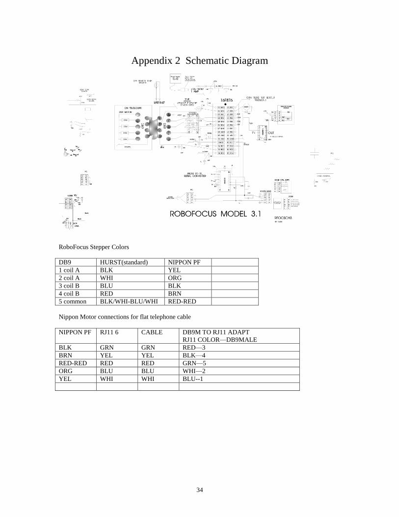
34
Appendix 2 Schematic Diagram
RoboFocus Stepper Colors
DB9 HURST(standard) NIPPON PF
1 coil A BLK YEL
2 coil A WHI ORG
3 coil B BLU BLK
4 coil B RED BRN
5 common BLK/WHI-BLU/WHI RED-RED
Nippon Motor connections for flat telephone cable
NIPPON PF RJ11 6 CABLE DB9M TO RJ11 ADAPT
RJ11 COLOR—DB9MALE
BLK GRN GRN RED—3
BRN YEL YEL BLK—4
RED-RED RED RED GRN—5
ORG BLU BLU WHI—2
YEL WHI WHI BLU--1
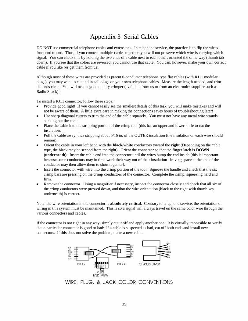
35
Appendix 3 Serial Cables
DO NOT use commercial telephone cables and extensions. In telephone service, the practice is to flip the wires
from end to end. Thus, if you connect multiple cables together, you will not preserve which wire is carrying which
signal. You can check this by holding the two ends of a cable next to each other, oriented the same way (thumb tab
down). If you see that the colors are reversed, you cannot use that cable. You can, however, make your own correct
cable if you like (or get them from us).
Although most of these wires are provided as precut 6-conductor telephone type flat cables (with RJ11 modular
plugs), you may want to cut and install plugs on your own telephone cables. Measure the length needed, and trim
the ends clean. You will need a good quality crimper (available from us or from an electronics supplier such as
Radio Shack).
To install a RJ11 connector, follow these steps:
Provide good light! If you cannot easily see the smallest details of this task, you will make mistakes and will
not be aware of them. A little extra care in making the connections saves hours of troubleshooting later!
Use sharp diagonal cutters to trim the end of the cable squarely. You must not have any metal wire strands
sticking out the end.
Place the cable into the stripping portion of the crimp tool (this has an upper and lower knife to cut the
insulation.
Pull the cable away, thus stripping about 5/16 in. of the OUTER insulation (the insulation on each wire should
remain).
Orient the cable in your left hand with the black/white conductors toward the right (Depending on the cable
type, the black may be second from the right). Orient the connector so that the finger latch is DOWN
(underneath). Insert the cable end into the connector until the wires bump the end inside (this is important
because some conductors may in time work their way out of their insulation--leaving space at the end of the
conductor may then allow them to short together).
Insert the connector with wire into the crimp portion of the tool. Squeeze the handle and check that the six
crimp bars are pressing on the crimp conductors of the connector. Complete the crimp, squeezing hard and
firm.
Remove the connector. Using a magnifier if necessary, inspect the connector closely and check that all six of
the crimp conductors were pressed down, and that the wire orientation (black to the right with thumb key
underneath) is correct.
Note: the wire orientation in the connector is absolutely critical. Contrary to telephone service, the orientation of
wiring in this system must be maintained. This is so a signal will always travel on the same color wire through the
various connectors and cables.
If the connector is not right in any way, simply cut it off and apply another one. It is virtually impossible to verify
that a particular connector is good or bad: If a cable is suspected as bad, cut off both ends and install new
connectors. If this does not solve the problem, make a new cable.
36
Appendix 4 Serial Ports and Cables Introduction
In the following discussion, we use DEVICE to stand for either Digital Dome Works, Dome Wizard, RoboFocus or
other device as may be appropriate to your installation.
The communication between the computer and the DEVICE is via a "serial" cable connected to a PC serial port,
called a COMmunications Port (for purposes of this discussion RS232 and ―serial‖ refer to the same thing). If the
settings for the software do not match the port, communication will not succeed. In this section, we'll talk about
COM ports.
A standard PC running a recent version of Windows (or alternative operating system) frequently has three serial
ports numbered COM1-COM3, which are often assigned to:
mouse (usually COM1)
spare(COM2)
modem (usually on COM3 in our port assignments)
Some PCs have a separate special input for the Mouse (PS/2 style), which frees the COM1 port for other uses.
A remote control observatory may require that the control computer have enough serial ports to serve:
mouse
modem (optional)
telescope
CCD (may be a parallel port rather than serial)
DEVICE
Task: You will need to assure that your computer has the correct number of RS232 ports to serve your needs, and
you will need to have the proper cables to run from your computer to the observatory. In this appendix, we will
discuss both issues.
Serial Cable Options
Regardless of how many conductors the long cable has, we only use three for the serial communication (e.g., black,
green, and yellow on 6-conductor cable).
We provide nominal 10-ft. signal cables to connect your PC to DEVICE. This will work fine if your computer is in
or next to the dome. However, if you need to run longer cables, you can order them from us or easily build and
install your own. For relatively short runs (roughly up to 50-75 feet), you can use standard six-conductor flat
telephone cable with standard six conductor connectors.
If you are at a substantial distance, say, 100 ft or more. You may need to run the cable in some type of conduit
underground, and you may want cable that is physically stronger. The cable for the RS232 can be almost any
reasonably low capacitance, three (or more) conductor cable, for example, twisted shielded pair. For long runs, use
reasonably large wire (e.g., 20 gauge conductors). We have used a variety of wire types, including ―thermostat‖
wire (4 conductor) and even Romex #14 building wire (2 wires plus ground).
The easiest and most flexible way to make the connections is to use a standard 6-conductor telephone jack (female)
with wire leads. You can then simply hook the proper wire color to each of your long wire conductors, and then use
our standard (or your own) phone cables for inside the dome and control room. The colors we use are Black
(ground, DB9-5), Yellow (PC in DB9-3), and Green (PC out DB9-2). You can also use various other types of
connectors (e.g. DB9, use numbers above plus jumper DB9-7 and 8). See the schematic of connectors in the rear of
this instruction manual for further details.
37
Parallel Cable Options
As noted, some CCD cameras require parallel cables. Standard lengths are 10-25 feet. However, you can make or
purchase cables up to 100 or more feet long; however, they do get quite expensive. If you are putting the cable in
conduit, you may not be able to get the connector through the conduit. Thus, you can’t easily install the connectors
ahead of time, test the cable, and then install it. This can make system checkout more difficult. Consult with your
CCD supplier for more information. Note that if your control room is far away from the observatory (more than 100
ft.), you will probably find it useful to install a computer in the dome, and run the system as ―Long distance
Remote‖ using a local network. This may save money, and is a more flexible system.
Multiple Serial Ports
As noted above, you may need to provide more serial ports in your computer. Many inexpensive "multi-port" cards
are available to add ports, and most of these cards are supported by modern Windows versions. However, the most
inexpensive cards may require an IRQ for each port, which your computer may not have available.
Since mid-2000, several new devices have come to market. There are now internal cards that provide 4 or more
serial ports that do NOT use IRQs. You can find these by searching on the Internet. Costs will be in the $125-250
range. A second development is the wider use of USB ports. Again, in recent months USB devices that offer four
or more serial ports have become available, also in the $125-250 price range. With these developments, adding
serial ports to non-laptops is much easier. Most of the rest of this appendix describes concerns for older port
expansion electronics.
If a computer is included in the DEVICE package, t already has the necessary cards installed and configured. If you
are using your own computer and need additional serial ports, you will need to add a new card to your PC (many
laptops will support additional ports via PCMCIA cards).
The programs that control each observatory component include a method of selecting a COM port. For example, in
DEVICE, it is done in the Configure. Check the instruction manual for your telescope and CCD software to find
how to set the COM/parallel port setting for those devices.
Proper operation requires that each component be connected to the physical port that has been assigned in its
software. Failure to plug into the correct, assigned port will result in a "failure to connect" or some similar error
message. If the connection is not successful, you will receive a message to that effect.
USB
Although we have no plans to implement a USB port on the Digital Dome Works hardware, some USB to Serial
converters have appeared which provide standard RS-232 serial ports and connect to the computer by USB port.
These devices come with driver software that makes the serial converter appear to software as a standard COM port.
Several converters may be operated in parallel via a USB Hub to gain multiple serial (and/or parallel) ports. These
converters are often restricted to use with Windows 95/98 (not NT), so the user must determine if a given converter
is suitable. Some software, expecting to communicate directly to a serial or parallel port’s hardware, may not be
able to exploit a USB converter- this is dependent upon the software itself. We have tested communications from
Digital Dome Works and The SKY via an USB to Serial converter and found both to work fine under Windows 98.
Extensive reliability testing under different mixes of hardware, tasks and multitasking has not been done, so we are
not aware of the possible problems a user may face.
The user should also be aware that the USB standard is in a state of evolution, and it is possible a substantial
investment in USB hardware could become useless if standards evolve unfavorably with respect to particular
combinations of hardware, software and operating system. We don’t expect this is likely, but since USB and related
standards are so new, support them is subject to future decisions of the companies involved.
38
Serial Port Expansion Cards
Modern PCs are supplied with two serial ports; one is a 9-pin male and the other a 25-pin female. Typically they are
designated as COM1 and COM2 respectively. If a mouse is supplied, it is connected in one of the following ways;
directly into the 9 pin serial connector, into its own ―PS/2‖ style jack, into the 25 pin connector via a 9 pin to 25 pin
adapter, or into its own specialized card input jack. Assuming the mouse is hooked either to COM1 or COM2, only
one COM port is free for accessories. There is a market for USB devices, which in principal can offer functions in
this area. USB is a serial bus standard, which allows multiple devices (mice, keyboards, and joysticks) to be
connected to a single wire. However, since the USB market is small, proprietary and expensive, we do not intend to
support it in the foreseeable future, so it will not be discussed here.
Depending upon the devices attached to the PC, you will have particular needs with respect to I/O ports. First, the
Observatory controller requires 1 COM port- our standard port is COM2, although all our software will support
COM1 through COM9. CCD cameras typically use a LPT (printer) port, but some require a serial port and others
require both. The Telescope mount will consume either another COM port or an LPT port depending upon the
particular mount design.
Modems can either use an existing port, or can supply one of their own- depending upon the modem’s design.
Internal modems always supply their own, often as COM3 so as not to conflict with COM1 and COM2 as supplied
by the main system board. External modems always need a 9 or 25 pin COM port, thereby using one supplied by
the main system board or expansion card.
If your system only requires 1 LPT port for the CCD, 1 COM port for the Observatory and 1 COM port for the
Telescope mount, it may be possible to set the system up without requiring additional COM/LPT port cards. The
key is to use an internal modem (if you need a modem) and ensure your computer main board accepts a PS/2 style
mouse (most motherboards less than 2 years old do). If your motherboard supports PS/2 mice, it might be just a
matter of purchasing a PS/2 style mouse, plugging it in and enabling PS/2 mouse functions via main system board
jumpers or CMOS settings. Windows 3.1 and up will directly recognize PS/2 mice (as will alternative operating
systems like Linux or BeOS). If your main system board does not support PS/2 mice, or you don’t have a sufficient
quantity of COM and LPT ports, you will most likely need an expansion card.
There are many variations of COM/LPT expansion cards, offering a wide array of port combinations, data rate
capabilities and connector styles. Costs will range from $10 for old style cards pulled from XT/AT machines to
several hundred dollars for the latest, most capable versions. In our experience, cards, which mix 2 or more COM
ports plus 1 or more LPT ports, are the most effective in this application. (Don’t ignore the XT/AT pulls out of
hand; they could do exactly what you need. If you buy one, be sure you know how to configure it!) We purchase
cards in the $40 to $150 price range, from Jameco Electronics (www.jameco.com) and JDR (www.jdr.com). We
select cards which provide additional 9 pin and 25 pin ports, or those with a large cable connector from which
dangle individual, short cables with 9 pin and 25 pin connectors. The particular UART chips employed on the card
are of little concern in this application and can be ignored unless you have special requirements. If you search
around, you may run into the 4 or more port serial boards, costing in the many hundreds to thousands of dollars.
These cards are very capable and are specially designed to not ―over consume‖ system resources as discussed below.
Unless your needs are stringent or you’ve exhausted other avenues, leave these fancy cards as a final alternative.
Although most of the COM/LPT expansion cards will be ―ISA‖ bus, you will some PCI bus cards. The
ads/salespeople will claim they are ―faster‖- certainly they are more expensive, but consider the limiting factor in the
communications link is the device sending the data. PCI Vs ISA offer little or no performance difference with
respect to speed with which Telescopes or DEVICE transmit on COM/LPT ports. On the other hand, if you are
servicing an ISDN modem, a high throughput card is preferred.
Our experience is, the most important factor in selecting a card is the configurability. Specifically, each COM and
LPT port on a card will utilize one of a limited number of IRQ ―slots‖ on the main system board. Many other PC
functions also use them, typically leaving only several available for expansion card use. Consequently, it is often
the case that on a fancy, new multi port card there are one or more of the ports, which are useless because of a lack
39
of IRQ slots. In the scenario, some operating systems other than Windows have the advantage because many can
―share‖ IRQ slots among serial ports, thereby allowing you to more flexibly configure the computer. Windows is
certainly obsolete in this area. If you are not conversant with adding cards to PCs and dealing with IRQ/IO port
address setting with the consequent software configuration adjustments, there are a variety of do-it-yourself books
on the subject. Almost any store selling PC s or PC hardware will be willing to install one for you (for a sometimes
substantial cost). If you do give your computer to someone to work on, be SURE to back up any important or
irreplaceable data/software first!
Windows 95 and up will support COM ports greater than 4. Usually all that is necessary is to add the New
Hardware, and supply the correct IRQ and I/O address values. However, we have had mixed experience coaxing
Windows 95 to properly accept new ports contributed by older multi-port serial cards. If you are forced to use
Windows, you may end up being forced into purchasing more expensive, specialized cards to overcome this
recalcitrance. While offering very good performance, these cards will easily cost an additional $150 or more. Our
preferred brand is DigiBoard; this firm offers a 4-port ISA card for approximately $250, which is the cheapest we
were able to find. On the other hand, it might be a large time savings to use one of these boards, as it could
considerably simplify your hardware configuration.
Be sure to closely examine any available information regarding the card before you purchase. Try to ensure you can
choose from at least 6 different IRQ settings and at least 6 I/O address, or I/O port settings. These 2 parameters
indicate how flexibly you can configure the card to ―work around‖ other cards/hardware installed in your system.
Unfortunately, the cost of the card is somewhat proportional to its ―configurability‖. The particular IRQ and I/O
settings offered by these cards are surprisingly standard. Once you reach the 6 IRQ and 6 I/O address threshold you
can consider the card quite flexible. If the card doesn’t offer that level of configurability, and you still want it, you
should be sure you understand how you will use the configuration options it offers.
The following is a somewhat extreme example of what one may go through while trying to add serial ports to a PC.
If you aren’t confident you can work through problems such as this, please consult a PC technician or call us.
Assume you need 1 more COM and 1 more LPT port. You find a card, which offers 4 serial ports each configurable
for COM1 through COM5 (IRQ 2,3,5,7,9) and one LPT port configurable from LPT1 to LPT3 (IRQ 5,7) for the
LPT port. You already have COM1, COM2 and LPT1 from the main system board and COM3 from an internal
modem. Your mouse is PS/2. Your choices are somewhat limited, but by leaving a couple serial ports ―useless‖,
you can almost do what you need. From examining your Modem settings you find your modem uses IRQ 5. COM1
and COM2, by tradition, occupy IRQ 3 and 4. Thus you have only IRQ 7 and 9 available for COM5. LPT1,
supplied by your main board, uses IRQ 7. Note, this board won’t let you use IRQ numbers over 9, which is limiting
your assignment of COM port IRQs. A more configurable card selection would allow the use of IRQs like 10,11,12,
and 15. You could assign IRQ9 to COM5, and IRQ7 to LPT2. First, you must find out if any other hardware is
already using IRQ9. Soundcards, SCSI cards, and LAN boards are likely candidates. If IRQ9 is already in use, you
are faced with a hardware reconfiguration job to free it up, which could be impossible- or you must find an
alternative expansion card. For the LPT port, we can’t use IRQ5 because the modem needs it, so we must use IRQ 7
instead. We note it is already assigned to LPT1, but since IRQ lines are infrequently used on printer ports (unlike
COM ports which require them) we will cross our fingers and hope there are no software conflicts. Now, even if
everything works, you still have 3 unusable COM ports on your new card because of the lack of IRQ configurability.
Consequently, this card is rather a poor choice since you can’t get it properly set up- hence the importance of closely
examining both your PC s configuration and the prospective expansion card.
Serial Communications Troubleshooting
If you have difficulty getting the PC and DEVICE to communicate, there are several areas to investigate. The
suggestions below start with the easiest first.
System Verification. One of the first steps is to verify that the basic equipment is working. If you have a COM port
that works (for example, one that currently serves the telescope), you may temporarily connect the DEVICE (with
PC-SBC adapter) to that port. Set the DEVICE Com port to the same setting that you were using for the port (e.g.,

40
in the telescope control software). If you now establish connection, you will prove that the control program and the
device are both operating correctly, the cables are good, and that the problem is in configuring or identifying the
proper COM port.
If you still do not connect, you may have a bad cable or connector. Try substituting another cable or adapter and
retry the connection.
User of Double Female Device. We can supply a double female adapter that accepts a telephone type connector on
each end. The device includes two small LED lamps wired onto our GRN and YEL wires. When connected into the
serial line to the DEVICE, these lamps will normally show GRN. (I.e. both the PC and the DEVICE are listening).
Each lamp will blink RED when a transmission occurs. Thus, if a normal command is sent (such as GET INFO),
one lamp will flicker RED for about a tenth of a second (look sharp—it’s quick!). Normally, in less than a second,
DEVICE will respond and the second lamp will flicker RED showing transmission back to the PC. Using these
indicators, you can determine where and in what direction the communication failure is occurring. In conditions of
high ambient light it may be difficult to see the red flicker indicating communication- so please look carefully.
If you are unable to produce a usable COM port for the DEVICE, you may require assistance either to change
internal settings in the computer (as discussed above) or to install internal cards in the PC to provide additional
COM ports as discussed above. Please feel free to call us for help.
41
Appendix 5 ASCOM Scripting
The RoboFocus Control Program exposes an ActiveX interface and can be invoked with syntax similar to this
VBScript example:
Set myRF = CreateObject("RoboFocus.FocusControl")
msgbox myRF.actOpenComm()
msgbox "Comm port status: " & myRF.getCommStatus()
msgBox "Firmware version: " & myRF.getFirmwareVersion()
myRF.actCloseComm()
This code starts an instance of the RoboFocus Control Program, opens the comm port, displays the comm port
status, and queries the device for the firmware version and displays it, then closes the comm port.
Below is a list of all the functions exposed by the RoboFocus Control Program for use by client software. For a
VBScript example of each function call, see RoboFocusExample.vbs, which is included on the CD.
Functions that Return Settings:
getFirmwareVersion() As String
Returns the firmware version if connected, or the string ―Not Connected‖ if not.
getPosition() As Integer
Returns the current position of RoboFocus if connected, or –1 if not.
getDelta() As Integer
Returns the current delta value (the amount that a click on ―In‖ or ―Out‖ will move RoboFocus. Returns –1 if not
connected.
getUserButtonState(ByVal Button As Integer) As Boolean
Takes a button number from 1 through 4, and returns the current state of the button, True for on and False for off.
getUserButtonCaption(ByVal Button As Integer) As String
Takes a button number from 1 through 4, and returns the current caption of that button.
getCommStatus() As Boolean
Returns the current status of the comm port specified in the RoboFocus Configuration screen, true if connected, and
False if not.
getOpenCommPortOnStartup() As Boolean
Returns the state of the ―Open Comm Port on Startup‖ checkbox on the Configuration screen, true if checked and
False if not.
getBacklashDirection() As Integer
Returns the value of the Backlash Direction radio buttons on the Configuration screen. Off = 1, In = 2, and Out = 3.
Returns –1 if not connected.
getBacklashSteps() As Integer
Returns the value of the BacklashSteps field on the Configuration screen, or returns –1 if not connected.

42
getMaxTravel() As Integer
Returns the value of the Maximum Travel field on the Configuration screen, or returns –1 if not connected.
getKeepMainOnTop() As Boolean
Returns the state of the ―Keep Main Form on Top‖ checkbox on the Configuration screen, True if checked and False
if not.
getDataTraffic(ByVal Direction As Integer) As String
Takes an integer indicating which data stream to return, 1 for data that has been sent to RoboFocus and 2 for
received data. Returns a string containing up to 1000 characters.
getCmdActive() as Boolean
Returns true if a command is currently being processed by the hardware, and false if not.
getTempCompAbsRel() As Integer
Returns 0 if Temperature Compensation is in Compute Position mode, 1 if in Compute Slope or Slope
Setup modes, -1 if not connected or no dataset open.
getAutoRate() As Single
Returns the value in the Auto Rate field, or -1 if no dataset loaded.
getDeadZone() As Integer
Returns the value in the Dead Zone field, or -1 if no dataset loaded.
Functions that Alter Settings:
setPosition(ByVal position As Long) As Long
Takes a position in Long format. Valid values are 0 through 65535. Sets the current position of RoboFocus to the
passed value. Returns the position after the action is complete, or –1 if RoboFocus is offline. If the command was
successful, the current position returned will equal the passed value.
setDelta(ByVal Delta As Long) As Long
Takes a delta value in Long format. Valid values are 0 through 65535. Sets delta to the passed value. Returns the
delta value after the action is complete, or –1 if RoboFocus is offline. If the command was successful, the current
delta returned will equal the passed value.
setUserButtonCaption(ByVal Button As Integer, ByVal Caption As String) As String
Takes an integer button number from 1 through 4, and a caption string. Sets the caption of the specified button to the
string. Returns the caption after the action is complete. If the command was successful, the returned caption will
equal the passed string.
setOpenCommPortOnStartup(ByVal OpenPort As Boolean) As Boolean
Takes a Boolean value and sets the ―Open Comm Port on Startup‖ checkbox accordingly. Returns the setting of the
checkbox after the action is complete. If the command was successful, the returned value will equal the passed
value.
setBacklashDirection(ByVal Dir As Integer) As Integer
Takes an integer direction, 1 for No Backlash, 2 for In, and 3 for Out. Sets the Backlash Direction to the specified
direction, and returns the direction value after the action is complete, or –1 if RoboFocus is offline. If the command
was successful, the returned value will equal the passed value.
setBacklashSteps(ByVal backlashSteps As Long) As Long
Takes a Steps value in Long format. Valid values are 0 through 65535. Sets Backlash Steps to the passed value, and

43
returns the Steps value after the action is complete, or –1 if RoboFocus is offline. If the command was successful,
the returned value will equal the passed value.
setMaxTravel(ByVal maxTravel As Long) As Long
Takes a value for Maximum Travel in Long format. Valid values are 0 through 65535. Sets Maximum Travel to the
passed value, and returns the Maximum Travel value after the action is complete, or –1 if RoboFocus is offline. If
the command was successful, the returned value will equal the passed value.
setKeepMainOnTop(ByVal KeepMainOnTop As Boolean) As Boolean
Takes a Boolean value and sets the ―Keep Main Form on Top‖ checkbox accordingly. Returns the setting of the
checkbox after the action is complete. If the command was successful, the returned value will equal the passed
value.
setTempCompAbsRel(ByVal absRel As Integer) As Integer
If absRel = 0, Compute Position mode will be selected. AbsRel = 1 selects Compute Slope mode. The
resulting mode is returned as a 0 or 1. If no dataset has been loaded, or the comm port is not open, no
change results, and a –1 is returned.
setAutoRate(ByVal autoRate As Single) As Single
Sets the contents of the Auto Rate field, and returns the passed Auto Rate Interval if successful. Returns a -
1 if no dataset is loaded.
setDeadZone(ByVal deadZone As Integer) As Integer
Sets the contents of the Dead Zone field, and returns the passed Dead Zone if successful. Returns a -1 if no
dataset is loaded.
Functions that Perform an Action:
actGoToPosition(ByVal position As Long) As Boolean
Takes a position value between 1 and 65535, and moves RoboFocus to that position. Returns True if RoboFocus is
online, or False if not. Equivalent to entering a number in the ―Position‖ field and pressing enter.
actStop() As Boolean
Sends a Stop command to RoboFocus. Returns True if RoboFocus is online, or False if not. Equivalent to clicking
the ―Stop‖ button.
actIn() As Boolean
Commands RoboFocus to go In the amount of ticks specified in the Delta field. Returns True if RoboFocus is
online, or False if not. Equivalent to clicking the ―In‖ button.
actOut() As Boolean
Commands RoboFocus to go Out the amount of ticks specified in the Delta field. Returns True if RoboFocus is
online, or False if not. Equivalent to clicking the ―Out‖ button.
actRefresh() As Boolean
Queries the RoboFocus hardware for its current settings. Returns True if RoboFocus is online, or False if not.
Equivalent to clicking the ―Refresh‖ button.
actUserButtonToggle(ByVal Button As Integer) As Boolean
Takes an integer value from 1 through 4 and toggles the specified User Button. Returns the User Button state after
the action is completed.

44
actOpenComm() As Boolean
Opens the Comm Port (if it’s currently closed.) Returns the status of the comm port after the action is completed.
actCloseComm() As Boolean
Closes the Comm Port (if it’s currently open.) Returns the status of the comm port after the action is completed.
actTempCompManual() As Boolean
Performs a click on the Manual Button, and returns true if click worked, or false if offline or no dataset.
actTempCompAuto() As Boolean
Performs a click on the Auto Button, and returns true if successful, or false if offline or no dataset.
actLoadTempCompFile(ByVal TCFile As String) As Boolean
TCFile is the path and name of a valid TCD (Temperature Compensation Data) file. The file is opened and
the coefficients are calculated. Returns true if the file loaded successfully, false if not.
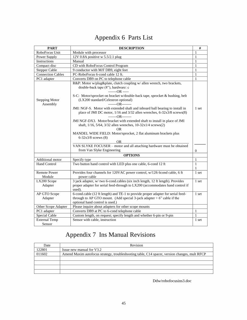
45
Appendix 6 Parts List
PART DESCRIPTION #
RoboFocus Unit Module with processor 1
Power Supply 12V 0.8A positive w 5.5/2.1 plug 1
Instructions Manual 1
Compact disc CD with RoboFocus Control Program 1
Stepper Cable 9 conductor with M/F DB9, eight feet 1
Connection Cables PC-RoboFocus 6-cond cable 12 ft. 1
PC1 adapter Converts DB9 on PC to telephone cable 1
Stepping Motor
Assembly
R&P: Motor w/plug&plate, clutch coupling w/ allen wrench, two brackets,
double-back tape (8‖), hardware: c
-------OR -----
S-C: Motor/sprocket on bracket w/double-back tape, sprocket & bushing, belt
(LX200 standard/Celestron optional)
-------OR--------
JMI: NGF-S. Motor with extended shaft and inboard ball bearing to install in
place of JMI DC motor, 1/16 and 3/32 allen wrenches, 6-32x3/8 screws(8)
-------OR--------
JMI NGF-DX3. Motor/bracket with extended shaft to install in place of JMI
shaft, 1/16, 5/64, 3/32 allen wrenches, 10-32x1/4 screws(2)
OR
MANDEL WIDE FIELD: Motor/sprocket, 2 flat aluminum brackets plus
6-32x3/8 screws (8)
OR_____________________________________
VAN SLYKE FOCUSER – motor and all attaching hardware must be obtained
from Van Slyke Engineering
1 set
0
OPTIONS
Additional motor Specify type 1
Hand Control Two button hand control with LED plus one cable, 6-cond 12 ft 1
1
Remote Power
Module
Provides four channels for 120VAC power control, w/12ft 6cond cable, 6 ft
power cable
1 set
LX200 Scope
Adapter
3 jack adapter, w/ two 6-cond.cables (six inch length, 12 ft length). Provides
proper adapter for serial feed-through to LX200 (accommodates hand control if
used).
1 set
AP GTO Scope
Adapter
6-cond.cable (12 ft length) and TE-1 to provide proper adapter for serial feed-
through to AP GTO mount. (Add special 3-jack adapter + 6‖ cable if the
optional hand control is used.)
1 set
Other Scope Adapter Please inquire about adapters for other scope mounts
PC1 adapter Converts DB9 at PC to 6-cond telephone cable 1
Special Cable Custom length, on request; specify length and whether 6-pin or 9-pin 1
External Temp
Sensor
Sensor with cable, instruction 1 set
Appendix 7 Ins Manual Revisions
Date Revision
122801 Issue new manual for V3.2
011602 Amend Maxim autofocus strategy, troubleshooting table, C14 spacer, version changes, mult RFCP
Ddw/robofocusins3.doc