Embed Size (px)
Citation preview
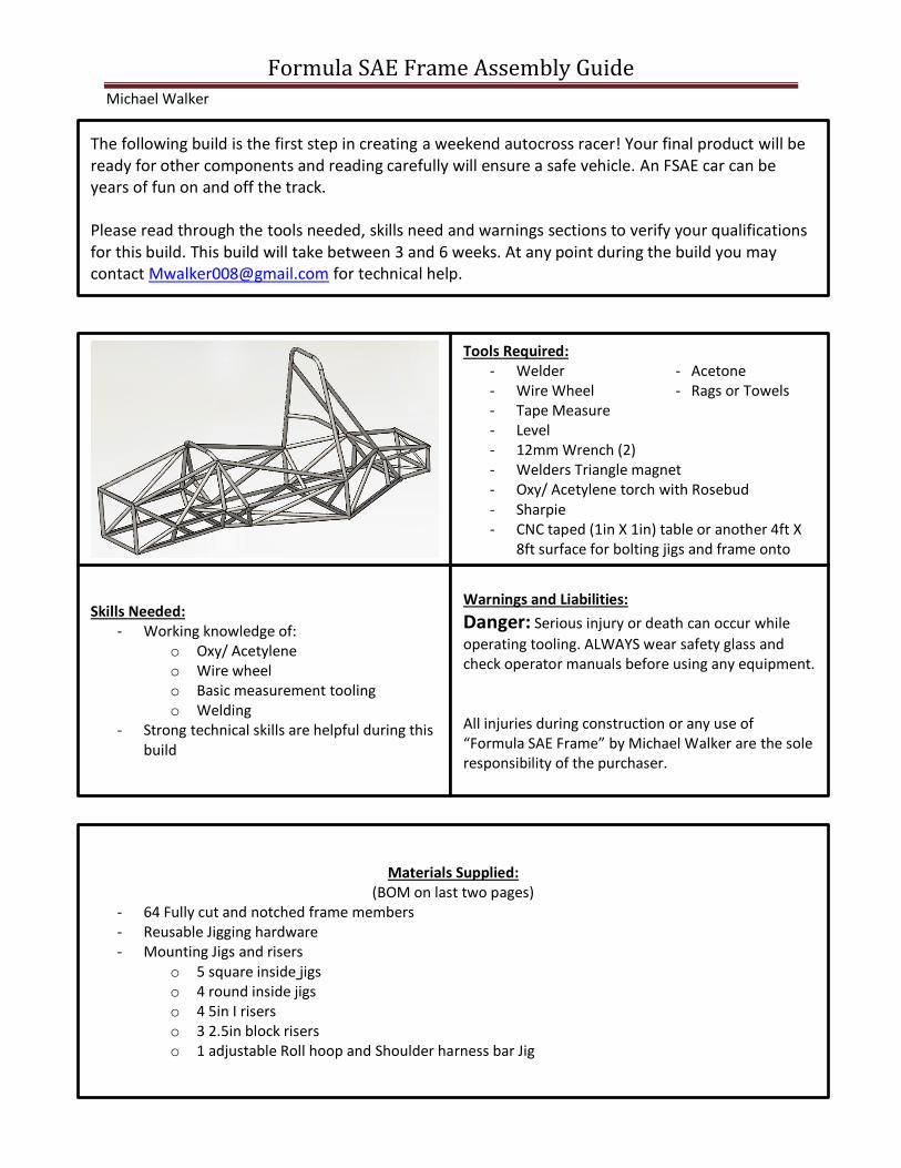
Formula SAE Frame Assembly Guide Michael Walker
Skills Needed: - Working knowledge of:
o Oxy/ Acetylene o Wire wheel o Basic measurement tooling o Welding
- Strong technical skills are helpful during this build
Warnings and Liabilities:
Danger: Serious injury or death can occur while
operating tooling. ALWAYS wear safety glass and check operator manuals before using any equipment. All injuries during construction or any use of “Formula SAE Frame” by Michael Walker are the sole responsibility of the purchaser.
Tools Required: - Welder - Acetone - Wire Wheel - Rags or Towels - Tape Measure - Level - 12mm Wrench (2) - Welders Triangle magnet - Oxy/ Acetylene torch with Rosebud - Sharpie - CNC taped (1in X 1in) table or another 4ft X
8ft surface for bolting jigs and frame onto
Materials Supplied: (BOM on last two pages)
- 64 Fully cut and notched frame members - Reusable Jigging hardware - Mounting Jigs and risers
o 5 square inside jigs o 4 round inside jigs o 4 5in I risers o 3 2.5in block risers o 1 adjustable Roll hoop and Shoulder harness bar Jig
The following build is the first step in creating a weekend autocross racer! Your final product will be ready for other components and reading carefully will ensure a safe vehicle. An FSAE car can be years of fun on and off the track. Please read through the tools needed, skills need and warnings sections to verify your qualifications for this build. This build will take between 3 and 6 weeks. At any point during the build you may contact [email protected] for technical help.
Formula SAE Frame: 2
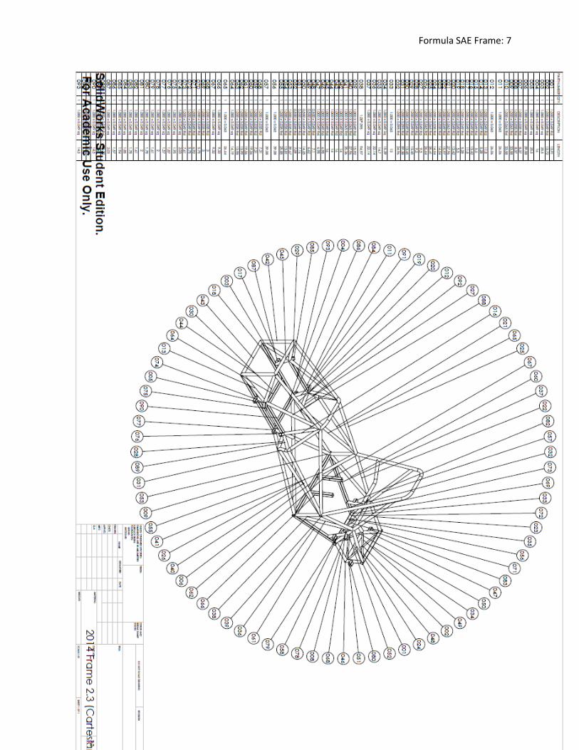
Section 2: Assembly Unless instructed otherwise follow each step that follows tack all joint assembled. Be sure to re-measure all tube locations after welding to ensure proper fit. (Tip: The last page of this manual is a full drawing and part
number labeled schematic)
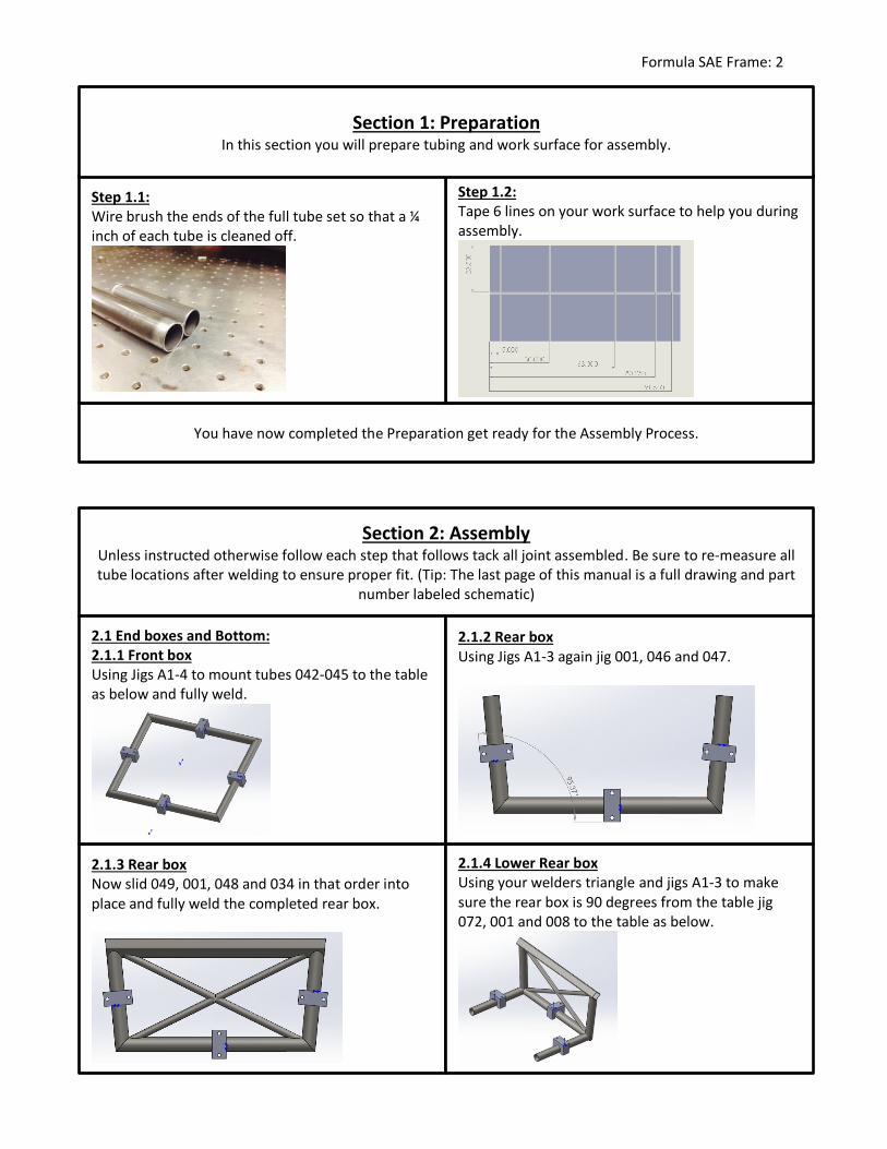
2.1.3 Rear box Now slid 049, 001, 048 and 034 in that order into place and fully weld the completed rear box.
2.1.4 Lower Rear box Using your welders triangle and jigs A1-3 to make sure the rear box is 90 degrees from the table jig 072, 001 and 008 to the table as below.
2.1 End boxes and Bottom: 2.1.1 Front box Using Jigs A1-4 to mount tubes 042-045 to the table as below and fully weld.
You have now completed the Preparation get ready for the Assembly Process.
Step 1.2: Tape 6 lines on your work surface to help you during assembly.
Step 1.1: Wire brush the ends of the full tube set so that a ¼ inch of each tube is cleaned off.
Section 1: Preparation In this section you will prepare tubing and work surface for assembly.
2.1.2 Rear box Using Jigs A1-3 again jig 001, 046 and 047.
Formula SAE Frame: 3
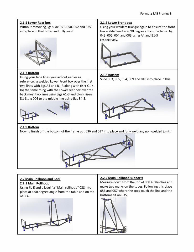
2.1.5 Lower Rear box Without removing jigs slide 051, 050, 052 and 035 into place in that order and fully weld.
2.1.6 Lower Front box Using your welders triangle again to ensure the front box welded earlier is 90 degrees from the table. Jig 043, 005, 004 and 003 using A4 and B1-3 respectively.
2.1.8 Bottom Slide 053, 055, 054, 009 and 010 into place in this.
2.1.7 Bottom Using your tape lines you laid out earlier as reference Jig welded Lower Front box over the first two lines with Jigs A4 and B1-3 along with riser C1-4. Do the same thing with the Lower rear box over the back most two lines using Jigs A1-3 and block risers D1-3. Jig 006 to the middle line using Jigs B4-5.
2.1.9 Bottom Now to finish off the bottom of the frame put 036 and 037 into place and fully weld any non-welded joints.
2.2 Main Rollhoop and Back 2.2.1 Main Rollhoop Using Jig E and a level fix “Main rollhoop” 038 into place at a 90 degree angle from the table and on top of 006.
2.2.2 Main Rollhoop supports Measure down from the top of 038 4.88inches and make two marks on the tubes. Following this place 056 and 057 where the tops touch the line and the bottoms sit on 035.
Formula SAE Frame: 4
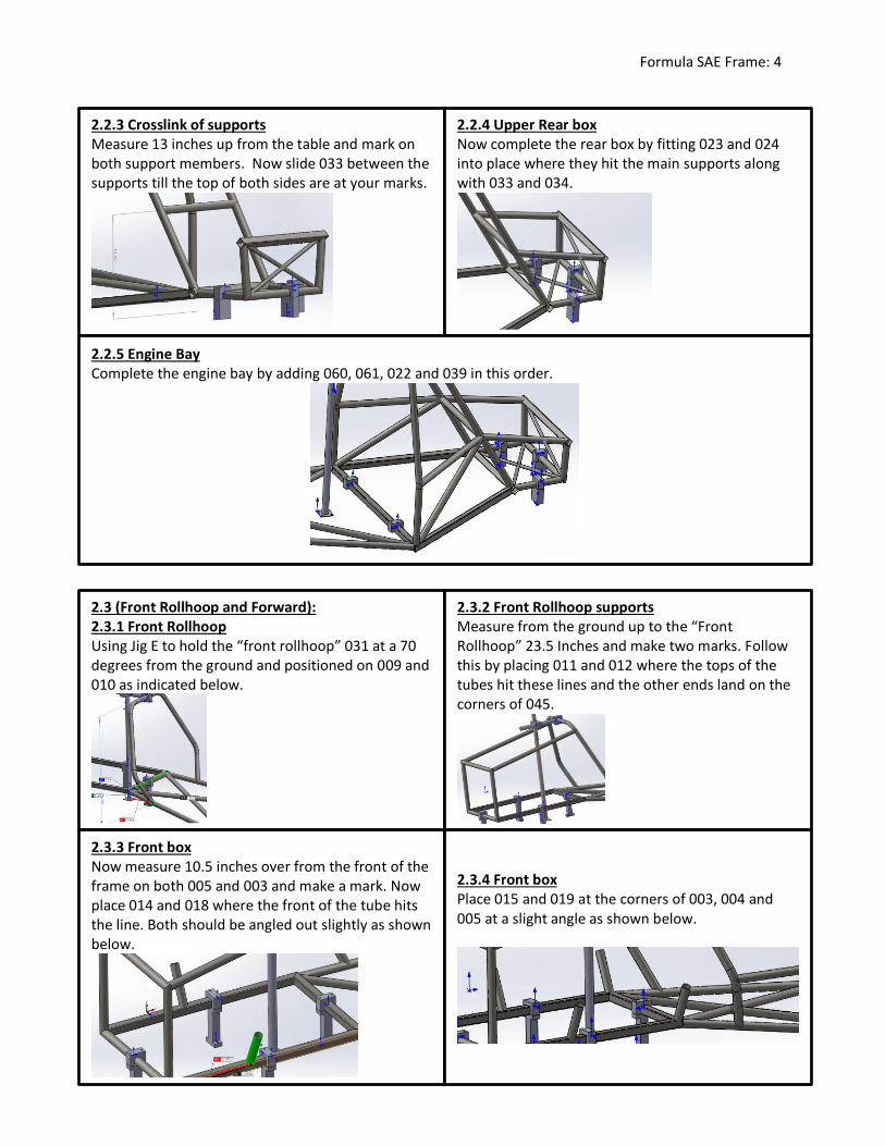
2.2.3 Crosslink of supports Measure 13 inches up from the table and mark on both support members. Now slide 033 between the supports till the top of both sides are at your marks.
2.2.4 Upper Rear box Now complete the rear box by fitting 023 and 024 into place where they hit the main supports along with 033 and 034.
2.2.5 Engine Bay Complete the engine bay by adding 060, 061, 022 and 039 in this order.
2.3 (Front Rollhoop and Forward): 2.3.1 Front Rollhoop Using Jig E to hold the “front rollhoop” 031 at a 70 degrees from the ground and positioned on 009 and 010 as indicated below.
2.3.2 Front Rollhoop supports Measure from the ground up to the “Front Rollhoop” 23.5 Inches and make two marks. Follow this by placing 011 and 012 where the tops of the tubes hit these lines and the other ends land on the corners of 045.
2.3.3 Front box Now measure 10.5 inches over from the front of the frame on both 005 and 003 and make a mark. Now place 014 and 018 where the front of the tube hits the line. Both should be angled out slightly as shown below.
2.3.4 Front box Place 015 and 019 at the corners of 003, 004 and 005 at a slight angle as shown below.
Formula SAE Frame: 5
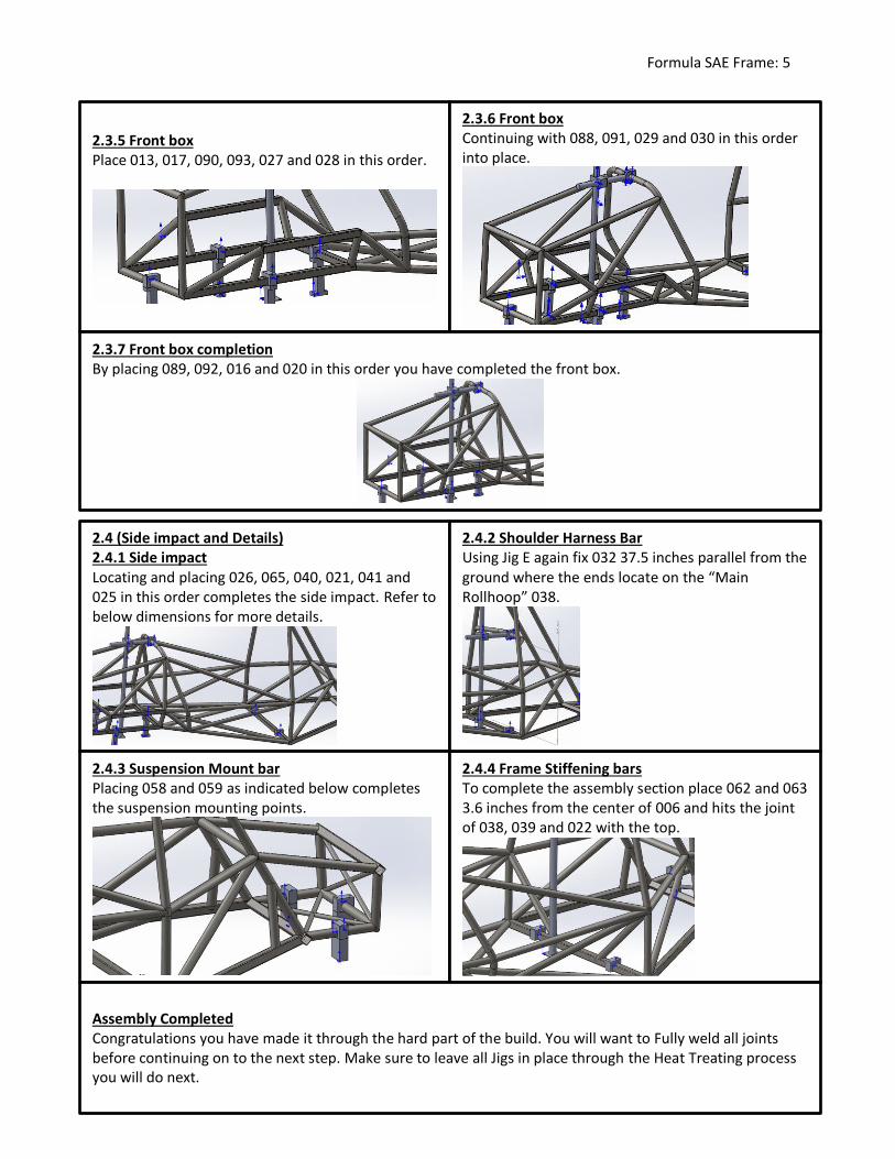
2.3.5 Front box Place 013, 017, 090, 093, 027 and 028 in this order.
2.3.6 Front box Continuing with 088, 091, 029 and 030 in this order into place.
2.3.7 Front box completion By placing 089, 092, 016 and 020 in this order you have completed the front box.
2.4 (Side impact and Details) 2.4.1 Side impact Locating and placing 026, 065, 040, 021, 041 and 025 in this order completes the side impact. Refer to below dimensions for more details.
2.4.3 Suspension Mount bar Placing 058 and 059 as indicated below completes the suspension mounting points.
2.4.4 Frame Stiffening bars To complete the assembly section place 062 and 063 3.6 inches from the center of 006 and hits the joint of 038, 039 and 022 with the top.
2.4.2 Shoulder Harness Bar Using Jig E again fix 032 37.5 inches parallel from the ground where the ends locate on the “Main Rollhoop” 038.
Assembly Completed Congratulations you have made it through the hard part of the build. You will want to Fully weld all joints before continuing on to the next step. Make sure to leave all Jigs in place through the Heat Treating process you will do next.
Formula SAE Frame: 6
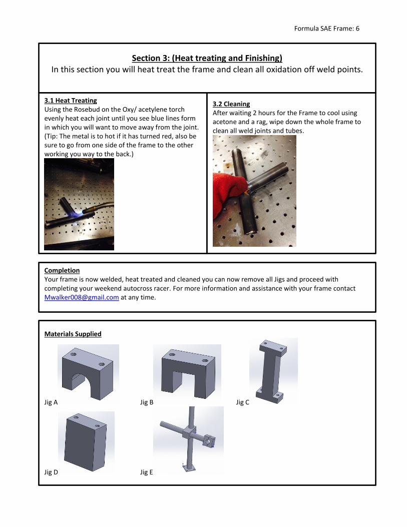
Section 3: (Heat treating and Finishing) In this section you will heat treat the frame and clean all oxidation off weld points.
3.1 Heat Treating Using the Rosebud on the Oxy/ acetylene torch evenly heat each joint until you see blue lines form in which you will want to move away from the joint. (Tip: The metal is to hot if it has turned red, also be sure to go from one side of the frame to the other working you way to the back.)
3.2 Cleaning After waiting 2 hours for the Frame to cool using acetone and a rag, wipe down the whole frame to clean all weld joints and tubes.
Completion Your frame is now welded, heat treated and cleaned you can now remove all Jigs and proceed with completing your weekend autocross racer. For more information and assistance with your frame contact [email protected] at any time.
Materials Supplied
Jig A Jig B Jig C
Jig D Jig E
Formula SAE Frame: 7