Embed Size (px)
Citation preview
GT 2200for central heatingand domestichot water production
GT 220for heating only
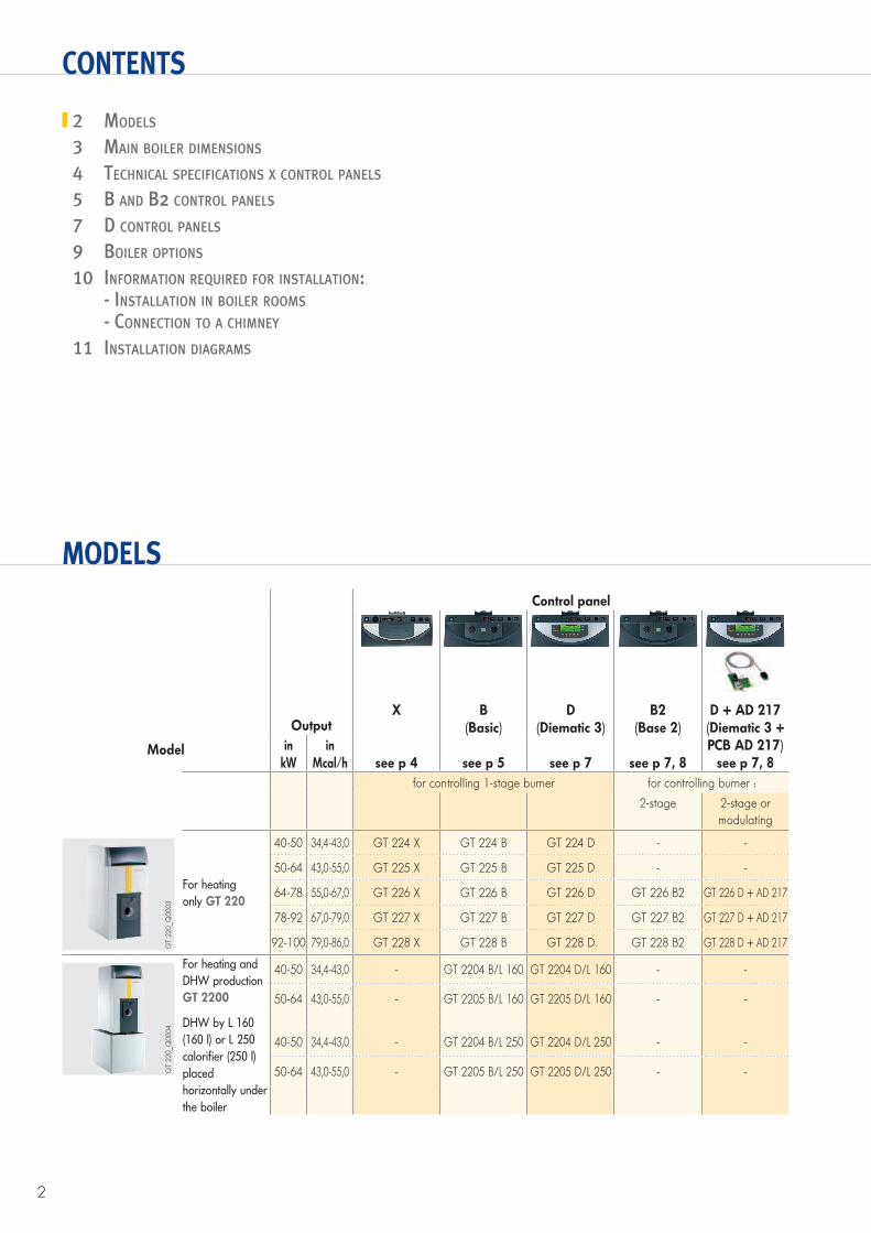
The GT 220s are low temperature cast iron boilers, with an useful output of 40 to 100 kW and high combustion efficiency (up to 95%) with a sealed pressurised combustion chamber to be fitted with a pressure jet fuel oil- or gas burner.They are available with various control panels and are all factory fitted with domestic hot water priority (except X-Panel) and can be used to control 1-stage burners (B, D control panels), 2-stage burners (B2) or modulating burners (DIEMATIC 3 control panel + AD 217 PCB):The GT 2200s can be delivered with the choice of a high performance 160- or 250-litre DHW calorifier, fitted with a “Titan Active System®” anode with self-adapting current for the maintenance-free protection of the tank.
CONDITIONS OF USEBoiler :
Max. working temperature: 100°CMax. working pressure: 4 barsThermostat adjustable from 30 to 90°CSafety thermostat: 110°C
Domestic hot water calorifier : Max. working temperature: 70°CMax. working pressure: 10 barsMax. usable pressure: 7 bars
Oil-/Gas
CE 1312BR4657
GT 220 CAST IRON FLOOR-STANDING FUEL OIL- / GAS-FIRED BOILERS
GT 220 : for hot water central heating only
GT 2200 : for hot water central heating and domestic
hot water production with a 160- or 250-litre calorifier
under the boiler
GT 2200GT 220
CONTENTS
MODELS
2 MODELS
3 MAIN BOILER DIMENSIONS
4 TECHNICAL SPECIFICATIONS X CONTROL PANELS
5 B AND B2 CONTROL PANELS
7 D CONTROL PANELS
9 BOILER OPTIONS
10 INFORMATION REQUIRED FOR INSTALLATION: - INSTALLATION IN BOILER ROOMS
- CONNECTION TO A CHIMNEY
11 INSTALLATION DIAGRAMS
2
Control panel
Model
OutputX
see p 4
B(Basic)
see p 5
D(Diematic 3)
see p 7
B2(Base 2)
see p 7, 8
D + AD 217(Diematic 3 + PCB AD 217)
see p 7, 8in
kWin
Mcal/h
for controlling 1-stage burner for controlling burner :
2-stage 2-stage or
modulating
For heating
only GT 220
40-50 34,4-43,0 GT 224 X GT 224 B GT 224 D - -
50-64 43,0-55,0 GT 225 X GT 225 B GT 225 D - -
64-78 55,0-67,0 GT 226 X GT 226 B GT 226 D GT 226 B2 GT 226 D + AD 217
78-92 67,0-79,0 GT 227 X GT 227 B GT 227 D GT 227 B2 GT 227 D + AD 217
92-100 79,0-86,0 GT 228 X GT 228 B GT 228 D GT 228 B2 GT 228 D + AD 217
For heating and
DHW production
GT 2200
DHW by L 160
(160 l) or L 250
calorifier (250 l)
placed
horizontally under
the boiler
40-50 34,4-43,0 - GT 2204 B/L 160 GT 2204 D/L 160 - -
50-64 43,0-55,0 - GT 2205 B/L 160 GT 2205 D/L 160 - -
40-50 34,4-43,0 - GT 2204 B/L 250 GT 2204 D/L 250 - -
50-64 43,0-55,0 - GT 2205 B/L 250 GT 2205 D/L 250 - -
GT
220_Q
0003
GT
220_Q
0004
3
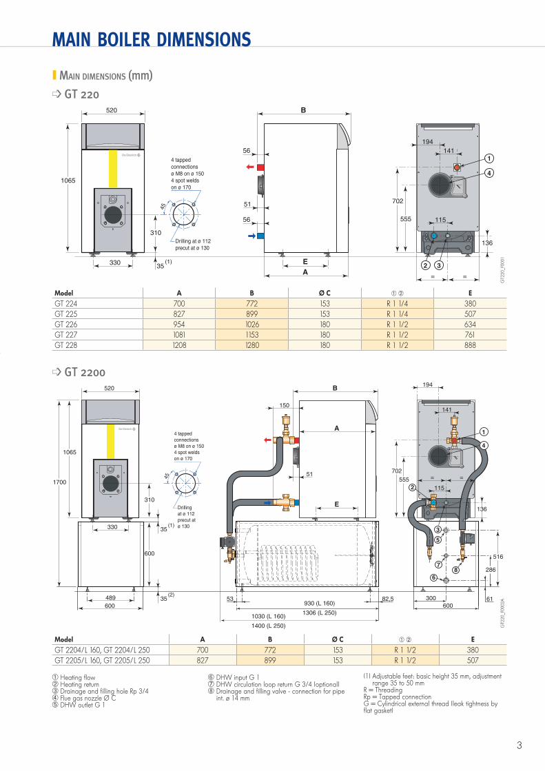
MAIN BOILER DIMENSIONS
MAIN DIMENSIONS (mm)
� GT 220
Model A B Ø C � � E
GT 224 700 772 153 R 1 1/4 380
GT 225 827 899 153 R 1 1/4 507
GT 226 954 1026 180 R 1 1/2 634
GT 227 1081 1153 180 R 1 1/2 761
GT 228 1208 1280 180 R 1 1/2 888
� GT 2200
300 61600
5
7
6
8 286
489
600 930 (L 160) 53 82,5
1306 (L 250) 1030 (L 160)
1400 (L 250)
4 tapped
connections
ø M8 on ø 150
4 spot welds
on ø 170
Drilling
at ø 112
precut at
ø 130
45
B
E
33035
310
1065
520
==
A
150
51
600
1700 555
136
516
1
2
4
3(1)
35(2)
702
115
141
194
GT2
20_F0
002A
4 tapped
connections
ø M8 on ø 150
4 spot welds
on ø 170
Drilling at ø 112
precut at ø 130
45
A
B
E33035
56
310
1065
520
==
56
51
555
136
1
2
4
3(1)
702
115
141
194
GT2
20_F0
001
Model A B Ø C � � E
GT 2204/L 160, GT 2204/L 250 700 772 153 R 1 1/2 380
GT 2205/L 160, GT 2205/L 250 827 899 153 R 1 1/2 507
� Heating flow� Heating return� Drainage and filling hole Rp 3/4� Flue gas nozzle Ø C� DHW outlet G 1
� DHW input G 1 DHW circulation loop return G 3/4 (optional) Drainage and filling valve - connection for pipe
int. ø 14 mm
(1) Adjustable feet: basic height 35 mm, adjustment range 35 to 50 mm
R = ThreadingRp = Tapped connectionG = Cylindrical external thread (leak tightness by flat gasket)
4
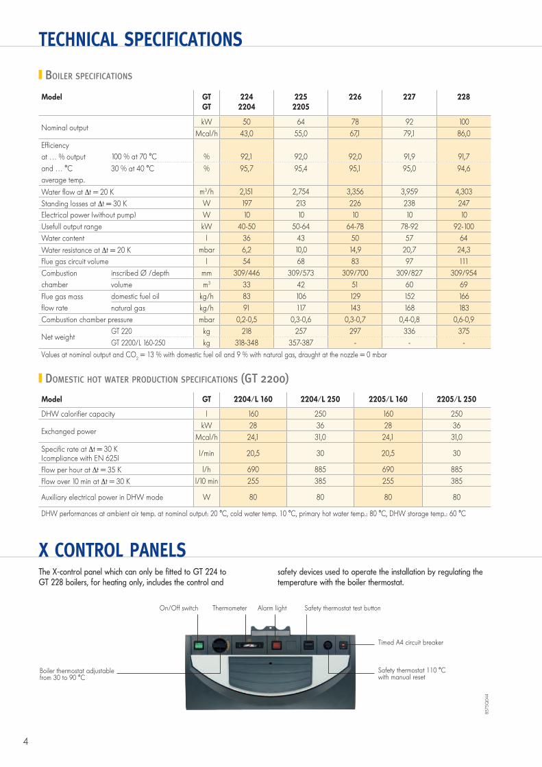
TECHNICAL SPECIFICATIONS
BOILER SPECIFICATIONS
DOMESTIC HOT WATER PRODUCTION SPECIFICATIONS (GT 2200)
Model GTGT
2242204
2252205
226 227 228
Nominal output kW 50 64 78 92 100
Mcal/h 43,0 55,0 67,1 79,1 86,0
Effi ciency
at … % output 100 % at 70 °C % 92,1 92,0 92,0 91,9 91,7
and … °C 30 % at 40 °C % 95,7 95,4 95,1 95,0 94,6
average temp.
Water fl ow at t = 20 K m3/h 2,151 2,754 3,356 3,959 4,303
Standing losses at t = 30 K W 197 213 226 238 247
Electrical power (without pump) W 10 10 10 10 10
Usefull output range kW 40-50 50-64 64-78 78-92 92-100
Water content l 36 43 50 57 64
Water resistance at t = 20 K mbar 6,2 10,0 14,9 20,7 24,3
Flue gas circuit volume l 54 68 83 97 111
Combustion inscribed Ø /depth mm 309/446 309/573 309/700 309/827 309/954
chamber volume m3 33 42 51 60 69
Flue gas mass domestic fuel oil kg/h 83 106 129 152 166
fl ow rate natural gas kg/h 91 117 143 168 183
Combustion chamber pressure mbar 0,2-0,5 0,3-0,6 0,3-0,7 0,4-0,8 0,6-0,9
Net weight GT 220 kg 218 257 297 336 375
GT 2200/L 160-250 kg 318-348 357-387 - - -
Values at nominal output and CO2 = 13 % with domestic fuel oil and 9 % with natural gas, draught at the nozzle = 0 mbar
Model GT 2204/L 160 2204/L 250 2205/L 160 2205/L 250
DHW calorifi er capacity l 160 250 160 250
Exchanged power kW 28 36 28 36
Mcal/h 24,1 31,0 24,1 31,0
Specifi c rate at t = 30 K (compliance with EN 625)
l/min 20,5 30 20,5 30
Flow per hour at t = 35 K l/h 690 885 690 885
Flow over 10 min at t = 30 K l/10 min 255 385 255 385
Auxiliary electrical power in DHW mode W 80 80 80 80
DHW performances at ambient air temp. at nominal output: 20 °C, cold water temp. 10 °C, primary hot water temp.: 80 °C, DHW storage temp.: 60 °C
X CONTROL PANELS The X-control panel which can only be fitted to GT 224 to GT 228 boilers, for heating only, includes the control and
safety devices used to operate the installation by regulating the temperature with the boiler thermostat.
Boiler thermostat adjustablefrom 30 to 90 °C
Thermometer Alarm light Safety thermostat test button
Timed A4 circuit breaker
Safety thermostat 110 °Cwith manual reset
On/Off switch
8575Q
044
5
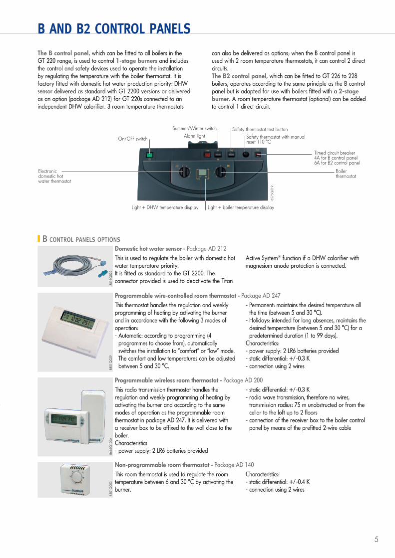
B AND B2 CONTROL PANELS
The B control panel, which can be fitted to all boilers in the GT 220 range, is used to control 1-stage burners and includes the control and safety devices used to operate the installation by regulating the temperature with the boiler thermostat. It is factory fitted with domestic hot water production priority: DHW sensor delivered as standard with GT 2200 versions or delivered as an option (package AD 212) for GT 220s connected to an independent DHW calorifier. 3 room temperature thermostats
can also be delivered as options; when the B control panel is used with 2 room temperature thermostats, it can control 2 direct circuits.The B2 control panel, which can be fitted to GT 226 to 228 boilers, operates according to the same principle as the B control panel but is adapted for use with boilers fitted with a 2-stage burner. A room temperature thermostat (optional) can be added to control 1 direct circuit.
Alarm light On/OFF switch
Light + boiler temperature display Light + DHW temperature display
Summer/Winter switch Safety thermostat test button
Safety thermostat with manual reset 110 °C
Timed circuit breaker4A for B control panel6A for B2 control panel
Electronic domestic hot water thermostat
Boiler thermostat
8575Q
019
B CONTROL PANELS OPTIONS
8518Q
022
Domestic hot water sensor - Package AD 212
This is used to regulate the boiler with domestic hot water temperature priority.It is fitted as standard to the GT 2200. The connector provided is used to deactivate the Titan
Active System® function if a DHW calorifier with magnesium anode protection is connected.
8801Q
029
Programmable wire-controlled room thermostat - Package AD 247
This thermostat handles the regulation and weekly programming of heating by activating the burner and in accordance with the following 3 modes of operation: - Automatic: according to programming (4
programmes to choose from), automatically switches the installation to “comfort” or “low” mode. The comfort and low temperatures can be adjusted between 5 and 30 °C.
- Permanent: maintains the desired temperature all the time (between 5 and 30 °C).
- Holidays: intended for long absences, maintains the desired temperature (between 5 and 30 °C) for a predetermined duration (1 to 99 days).
Characteristics: - power supply: 2 LR6 batteries provided- static differential: +/-0.3 K- connection using 2 wires
8666Q
120A
Programmable wireless room thermostat - Package AD 200
This radio transmission thermostat handles the regulation and weekly programming of heating by activating the burner and according to the same modes of operation as the programmable room thermostat in package AD 247. It is delivered with a receiver box to be affixed to the wall close to the boiler.Characteristics- power supply: 2 LR6 batteries provided
- static differential: +/-0.3 K- radio wave transmission, therefore no wires,
transmission radius: 75 m unobstructed or from the cellar to the loft up to 2 floors
- connection of the receiver box to the boiler control panel by means of the prefitted 2-wire cable
8801Q
003
Non-programmable room thermostat - Package AD 140
This room thermostat is used to regulate the room temperature between 6 and 30 °C by activating the burner.
Characteristics:- static differential: +/-0.4 K- connection using 2 wires
0 2 4 6 8 10 12 14 16 18 20 22 24
B
SUNDAY
D: DIEMATIC 3 CONTROL PANELS
6
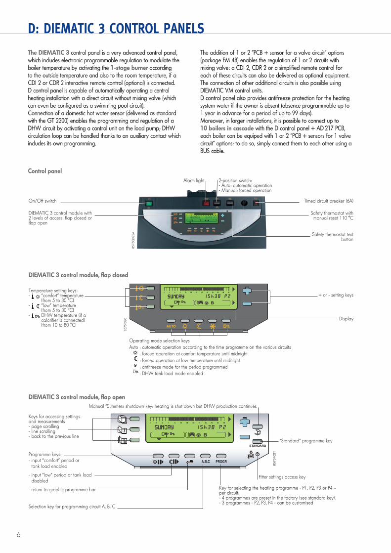
The DIEMATIC 3 control panel is a very advanced control panel, which includes electronic programmable regulation to modulate the boiler temperature by activating the 1-stage burner according to the outside temperature and also to the room temperature, if a CDI 2 or CDR 2 interactive remote control (optional) is connected.D control panel is capable of automatically operating a central heating installation with a direct circuit without mixing valve (which can even be configured as a swimming pool circuit).Connection of a domestic hot water sensor (delivered as standard with the GT 2200) enables the programming and regulation of a DHW circuit by activating a control unit on the load pump; DHW circulation loop can be handled thanks to an auxiliary contact which includes its own programming.
The addition of 1 or 2 “PCB + sensor for a valve circuit” options (package FM 48) enables the regulation of 1 or 2 circuits with mixing valve: a CDI 2, CDR 2 or a simplified remote control for each of these circuits can also be delivered as optional equipment.The connection of other additional circuits is also possible using DIEMATIC VM control units.D control panel also provides antifreeze protection for the heating system water if the owner is absent (absence programmable up to 1 year in advance for a period of up to 99 days).Moreover, in larger installations, it is possible to connect up to 10 boilers in cascade with the D control panel + AD 217 PCB, each boiler can be equiped with 1 or 2 “PCB + sensors for 1 valve circuit” options: to do so, simply connect them to each other using a BUS cable.
DIEMATIC 3 control module, flap closed
Temperature setting keys:- “comfort” temperature
(from 5 to 30 °C)- “low” temperature
(from 5 to 30 °C)- DHW temperature (if a
calorifier is connected)(from 10 to 80 °C)
+ or - setting keys
Operating mode selection keys
Auto : automatic operation according to the time programme on the various circuits
: forced operation at comfort temperature until midnight
: forced operation at low temperature until midnight
: antifreeze mode for the period programmed
: DHW tank load mode enabled
Display
8575F0
20
On/Off switch
Alarm light 2-position switch:- Auto: automatic operation- Manual: forced operation
DIEMATIC 3 control module with 2 levels of access: flap closed or flap open
Timed circuit breaker (6A)
Safety thermostat with manual reset 110 °C
Safety thermostat test button
8575Q
022A
Control panel
DIEMATIC 3 control module, flap open
STANDARD
A.B.C PROGR
0 2 4 6 8 10 12 14 16 18 20 22 24
B
SUNDAY
Keys for accessing settings and measurements- page scrolling- line scrolling- back to the previous line
Programme keys:- input “comfort” period or
tank load enabled
- input “low” period or tank load disabled
- return to graphic programme bar
Manual “Summer» shutdown key: heating is shut down but DHW production continues
“Standard” programme key
Key for selecting the heating programme - P1, P2, P3 or P4 – per circuit:- 4 programmes are preset in the factory (see standard key).- 3 programmes - P2, P3, P4 - can be customised
Fitter settings access key
Selection key for programming circuit A, B, C
8575F
021
7
D: DIEMATIC 3 CONTROL PANELS
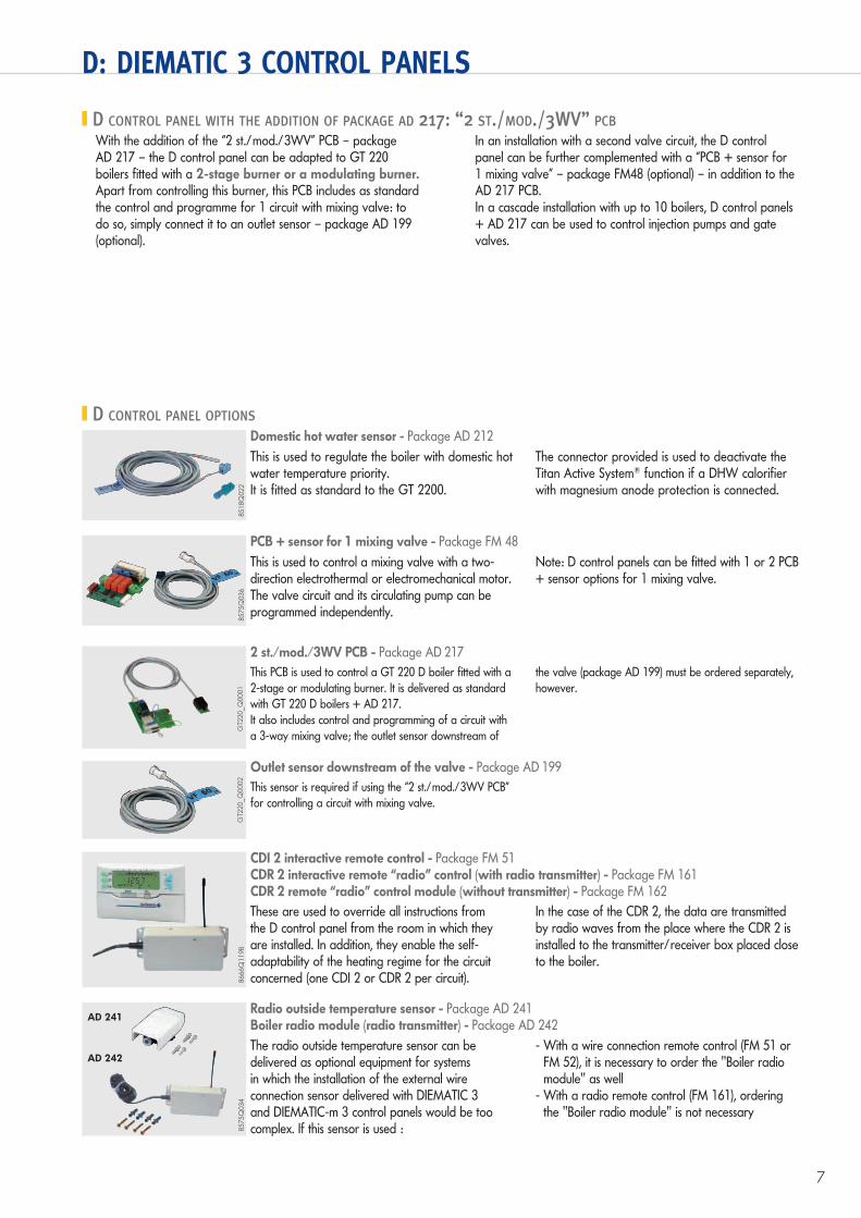
D CONTROL PANEL WITH THE ADDITION OF PACKAGE AD 217: “2 ST./MOD./3WV” PCB
With the addition of the “2 st./mod./3WV” PCB – package AD 217 – the D control panel can be adapted to GT 220 boilers fitted with a 2-stage burner or a modulating burner. Apart from controlling this burner, this PCB includes as standard the control and programme for 1 circuit with mixing valve: to do so, simply connect it to an outlet sensor – package AD 199 (optional).
In an installation with a second valve circuit, the D control panel can be further complemented with a “PCB + sensor for 1 mixing valve” – package FM48 (optional) – in addition to the AD 217 PCB. In a cascade installation with up to 10 boilers, D control panels + AD 217 can be used to control injection pumps and gate valves.
D CONTROL PANEL OPTIONS
8518Q
022
Domestic hot water sensor - Package AD 212
This is used to regulate the boiler with domestic hot water temperature priority. It is fitted as standard to the GT 2200.
The connector provided is used to deactivate the Titan Active System® function if a DHW calorifier with magnesium anode protection is connected.
8575Q
036
PCB + sensor for 1 mixing valve - Package FM 48
This is used to control a mixing valve with a two-direction electrothermal or electromechanical motor. The valve circuit and its circulating pump can be programmed independently.
Note: D control panels can be fitted with 1 or 2 PCB + sensor options for 1 mixing valve.
8666Q
119B
CDI 2 interactive remote control - Package FM 51 CDR 2 interactive remote “radio” control (with radio transmitter) - Package FM 161 CDR 2 remote “radio” control module (without transmitter) - Package FM 162
These are used to override all instructions from the D control panel from the room in which they are installed. In addition, they enable the self-adaptability of the heating regime for the circuit concerned (one CDI 2 or CDR 2 per circuit).
In the case of the CDR 2, the data are transmitted by radio waves from the place where the CDR 2 is installed to the transmitter/receiver box placed close to the boiler.
Radio outside temperature sensor - Package AD 241Boiler radio module (radio transmitter) - Package AD 242
The radio outside temperature sensor can be delivered as optional equipment for systems in which the installation of the external wire connection sensor delivered with DIEMATIC 3 and DIEMATIC-m 3 control panels would be too complex. If this sensor is used :
- With a wire connection remote control (FM 51 or FM 52), it is necessary to order the "Boiler radio module" as well
- With a radio remote control (FM 161), ordering the "Boiler radio module" is not necessary
8575Q
034
AD 241
AD 242
2 st./mod./3WV PCB - Package AD 217
This PCB is used to control a GT 220 D boiler fitted with a
2-stage or modulating burner. It is delivered as standard
with GT 220 D boilers + AD 217.
It also includes control and programming of a circuit with
a 3-way mixing valve; the outlet sensor downstream of
the valve (package AD 199) must be ordered separately,
however.
GT2
20_Q
0001
Outlet sensor downstream of the valve - Package AD 199
This sensor is required if using the “2 st./mod./3WV PCB”
for controlling a circuit with mixing valve.
GT2
20_Q
0002
8
D: DIEMATIC 3 CONTROL PANELS
BOILER OPTIONS
8575Q
037
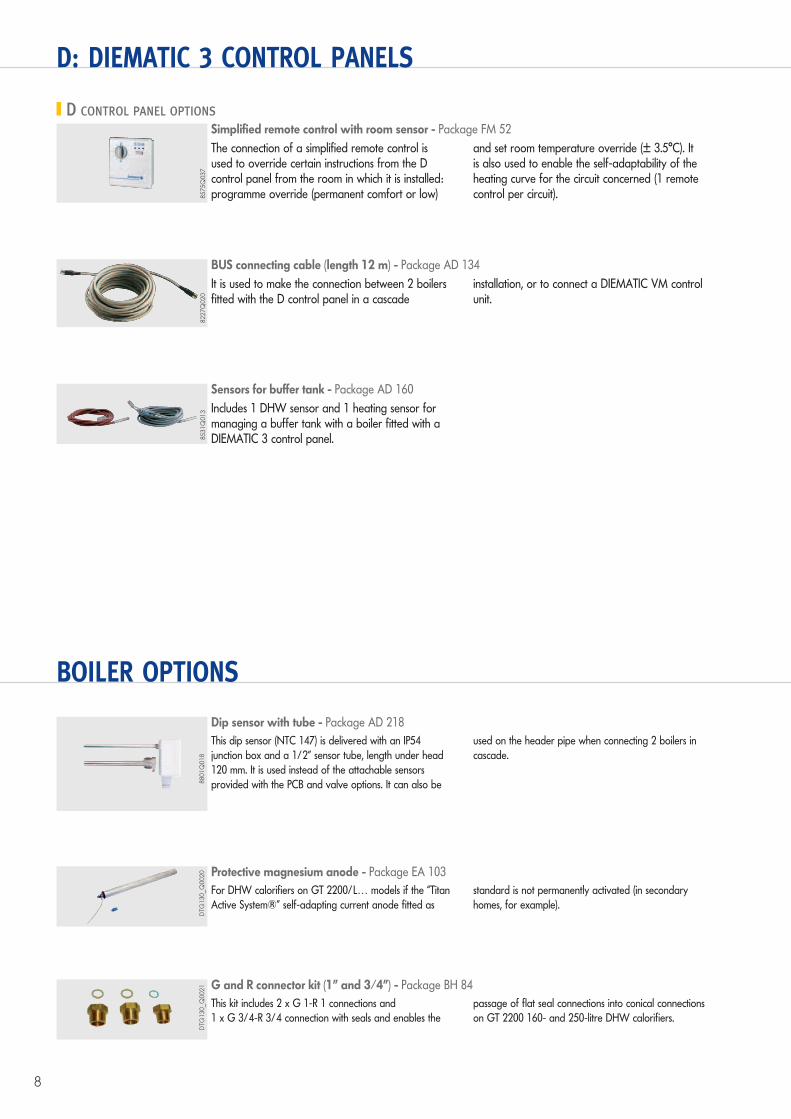
Simplified remote control with room sensor - Package FM 52
The connection of a simplified remote control is used to override certain instructions from the D control panel from the room in which it is installed: programme override (permanent comfort or low)
and set room temperature override (± 3.5°C). It is also used to enable the self-adaptability of the heating curve for the circuit concerned (1 remote control per circuit).
D CONTROL PANEL OPTIONS
8227Q
020
BUS connecting cable (length 12 m) - Package AD 134
It is used to make the connection between 2 boilers fitted with the D control panel in a cascade
installation, or to connect a DIEMATIC VM control unit.
8531Q
013
Sensors for buffer tank - Package AD 160
Includes 1 DHW sensor and 1 heating sensor for managing a buffer tank with a boiler fitted with a DIEMATIC 3 control panel.
Dip sensor with tube - Package AD 218
This dip sensor (NTC 147) is delivered with an IP54
junction box and a 1/2” sensor tube, length under head
120 mm. It is used instead of the attachable sensors
provided with the PCB and valve options. It can also be
used on the header pipe when connecting 2 boilers in
cascade.
8801Q
018
Protective magnesium anode - Package EA 103
For DHW calorifiers on GT 2200/L… models if the “Titan
Active System®” self-adapting current anode fitted as
standard is not permanently activated (in secondary
homes, for example).
DTG
130_Q
0020
G and R connector kit (1” and 3/4”) - Package BH 84
This kit includes 2 x G 1-R 1 connections and
1 x G 3/4-R 3/4 connection with seals and enables the
passage of flat seal connections into conical connections
on GT 2200 160- and 250-litre DHW calorifiers.
DTG
130_Q
0021
9
BOILER OPTIONS
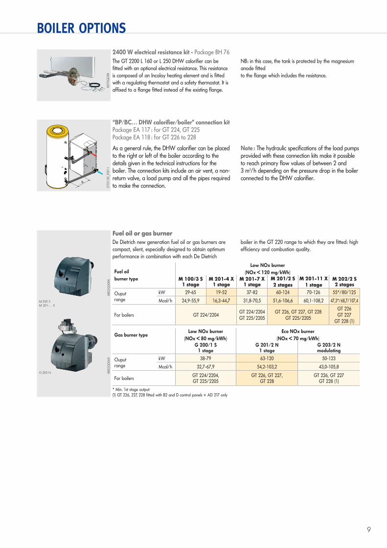
2400 W electrical resistance kit - Package BH 76
The GT 2200 L 160 or L 250 DHW calorifier can be
fitted with an optional electrical resistance. This resistance
is composed of an Incoloy heating element and is fitted
with a regulating thermostat and a safety thermostat. It is
affixed to a flange fitted instead of the existing flange.
NB: in this case, the tank is protected by the magnesium
anode fitted
to the flange which includes the resistance.
8575Q
038
“BP/BC… DHW calorifier/boiler” connection kitPackage EA 117 : for GT 224, GT 225Package EA 118 : for GT 226 to 228
As a general rule, the DHW calorifier can be placed to the right or left of the boiler according to the details given in the technical instructions for the boiler. The connection kits include an air vent, a non-return valve, a load pump and all the pipes required to make the connection.
Note : The hydraulic specifications of the load pumps provided with these connection kits make it possible to reach primary flow values of between 2 and 3 m3/h depending on the pressure drop in the boiler connected to the DHW calorifier.
A
BP/BC
racc droite 500
DTG
130_F0
011
Fuel oil or gas burner
De Dietrich new generation fuel oil or gas burners are
compact, silent, especially designed to obtain optimum
performance in combination with each De Dietrich
boiler in the GT 220 range to which they are fitted: high
efficiency and combustion quality.
M 200 SM 201-… X
G 200 N
* Min. 1st stage output(1) GT 226, 227, 228 fitted with B2 and D control panels + AD 217 only
Fuel oil
burner type
Low NOx burner
(NOx < 120 mg/kWh)
M 100/3 S1 stage
M 201-4 X1 stage
M 201-7 X1 stage
M 201/2 S
2 stages
M 201-11 X
1 stageM 202/2 S2 stages
Ouputrange
kW 29-65 19-52 37-82 60-124 70-126 55*/80/125
Mcal/h 24,9-55,9 16,3-44,7 31,8-70,5 51,6-106,6 60,1-108,2 47,3*/68,7/107,4
For boilers GT 224/2204GT 224/2204GT 225/2205
GT 226, GT 227, GT 228GT 225/2205
GT 226GT 227
GT 228 (1)
Gas burner type Low NOx burner
(NOx < 80 mg/kWh)
Eco NOx burner
(NOx < 70 mg/kWh)
G 200/1 S1 stage
G 201/2 N1 stage
G 203/2 Nmodulating
Ouputrange
kW 38-79 63-120 50-123
Mcal/h 32,7-67,9 54,2-103,2 43,0-105,8
For boilersGT 224/2204,GT 225/2205
GT 226, GT 227,GT 228
GT 226, GT 227GT 228 (1)
8802Q
008A
8802Q
0069
10
INFORMATION REQUIRED FOR INSTALLATION
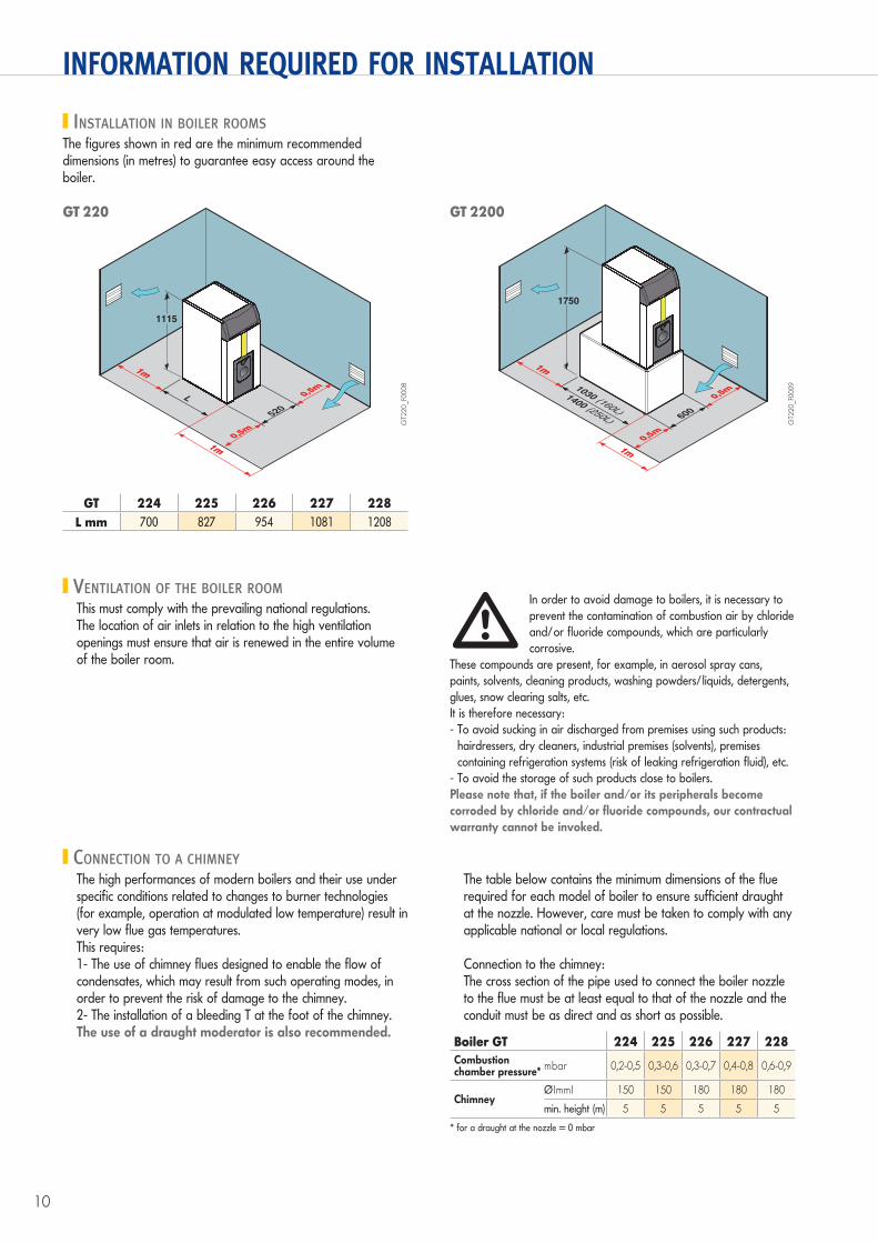
INSTALLATION IN BOILER ROOMS
The figures shown in red are the minimum recommended dimensions (in metres) to guarantee easy access around the boiler.
1115
520
0,5m
0,5m
0,5m
0,5m
L
1m1m
1m1m
GT2
20_F0
008
1750
600
0,5m
0,5m
0,5m
0,5m1030 (160L)
1400 (250L)
1m1m
1m1m
GT2
20_F0
009
GT 220 GT 2200
GT 224 225 226 227 228
L mm 700 827 954 1081 1208
VENTILATION OF THE BOILER ROOM
This must comply with the prevailing national regulations.The location of air inlets in relation to the high ventilation openings must ensure that air is renewed in the entire volume of the boiler room.
In order to avoid damage to boilers, it is necessary to
prevent the contamination of combustion air by chloride
and/or fluoride compounds, which are particularly
corrosive.
These compounds are present, for example, in aerosol spray cans,
paints, solvents, cleaning products, washing powders/liquids, detergents,
glues, snow clearing salts, etc.
It is therefore necessary:
- To avoid sucking in air discharged from premises using such products:
hairdressers, dry cleaners, industrial premises (solvents), premises
containing refrigeration systems (risk of leaking refrigeration fluid), etc.
- To avoid the storage of such products close to boilers.
Please note that, if the boiler and/or its peripherals become corroded by chloride and/or fluoride compounds, our contractual warranty cannot be invoked.
�
CONNECTION TO A CHIMNEY
The high performances of modern boilers and their use under specific conditions related to changes to burner technologies (for example, operation at modulated low temperature) result in very low flue gas temperatures.This requires:1- The use of chimney flues designed to enable the flow of condensates, which may result from such operating modes, in order to prevent the risk of damage to the chimney.2- The installation of a bleeding T at the foot of the chimney.The use of a draught moderator is also recommended.
The table below contains the minimum dimensions of the flue required for each model of boiler to ensure sufficient draught at the nozzle. However, care must be taken to comply with any applicable national or local regulations.
Connection to the chimney:The cross section of the pipe used to connect the boiler nozzle to the flue must be at least equal to that of the nozzle and the conduit must be as direct and as short as possible.
Boiler GT 224 225 226 227 228
Combustionchamber pressure*
mbar 0,2-0,5 0,3-0,6 0,3-0,7 0,4-0,8 0,6-0,9
ChimneyØ (mm) 150 150 180 180 180
min. height (m) 5 5 5 5 5
* for a draught at the nozzle = 0 mbar
11
INFORMATION REQUIRED FOR INSTALLATION
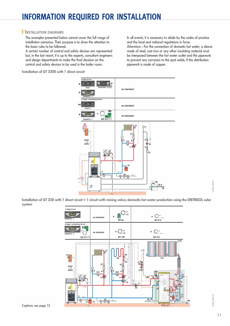
INSTALLATION DIAGRAMS
The examples presented below cannot cover the full range of installation scenarios. Their purpose is to draw the attention to the basic rules to be followed.A certain number of control and safety devices are represented but, in the last resort, it is up to the experts, consultant engineers and design departments to make the final decision on the control and safety devices to be used in the boiler room.
In all events, it is necessary to abide by the codes of practice and the local and national regulations in force.Attention : For the connection of domestic hot water, a sleeve made of steel, cast iron or any other insulating material must be interposed between the hot water outlet and this pipework to prevent any corrosion to the spot welds, if the distribution pipework is made of copper.
TS
N
�
50
189
9
9
9
28
29
27
27
32
30
16
33
2
26
21
50Hz
230V
as standard
as standard
as standard
AD 217 (1)
22 1
51
99
5211
27
°C °C
3
4
7
33
20°C
40
0
I
4A
STANDARD
MODE
PROGPROG
+
-
1 2 3 4 5 6 7
0 2 4 6 8 10 12 14 16 18 20 22 24
0
I
4A
4 5
6
7
81
2
3
3
4
5
6
7
8
9
0
I
4A
0 2 4 6 8 10 12 14 16 18 20 22 24
B E*
D
DIEMATIC 3
Basic
0
I
4A
4 5
6
7
81
2
3
3
4
5
6
7
8
9
B2
Basic 2
Easymatic
17
MERCREDI 15h38
0
I
4A
0 2 4 6 8 10 12 14 16 18 20 22 24
D
DIEMATIC 3
MERCREDI 15h38
1-stage burner
2-stage / modulating burner
89
99
26
65
99
5211
10
27
°C °C
44
23
4 109
131
130 87
88
126
114
46
8461
85
4
112b
29 30
329
9
27
90 7
230V
50HzSET
Dietrisol B
<>
33
24
56
25
81
112a
50
18916
2
21
50Hz
230V
22 1
51
99
5211
27
°C °C
3
4
7
AD 212FM 48
as standard
as standard
AD 212AD 217 AD 199(1)
TS
N
TS
N
17
TRIO DT ...
0
I
4A
0 2 4 6 8 10 12 14 16 18 20 22 24
DIEMATIC 3
1-stage burner
MERCREDI 15h38
0
I
4A
0 2 4 6 8 10 12 14 16 18 20 22 24
DIEMATIC 3
2-stage / modulating burner
MERCREDI 15h38
Captions: see page 12
GT2
20_F0
010
GT2
20_F0
011A
Installation of GT 2200 with 1 direct circuit
Installation of GT 220 with 1 direct circuit + 1 circuit with mixing valve; domestic hot water production using the DIETRISOL solar system
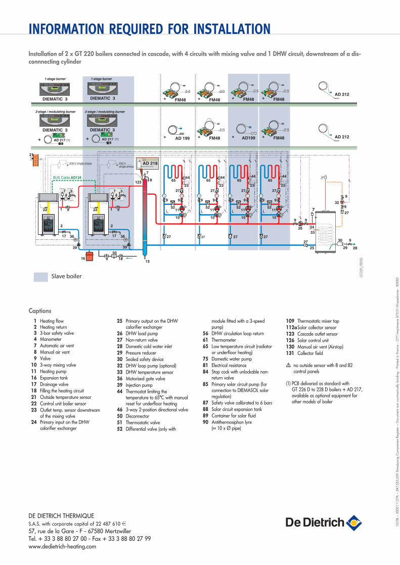
1 Heating flow 2 Heating return 3 3-bar safety valve 4 Manometer 7 Automatic air vent 8 Manual air vent 9 Valve 10 3-way mixing valve 11 Heating pump 16 Expansion tank 17 Drainage valve 18 Filling the heating circuit 21 Outside temperature sensor 22 Control unit boiler sensor 23 Outlet temp. sensor downstream
of the mixing valve 24 Primary input on the DHW
calorifier exchanger
25 Primary output on the DHW calorifier exchanger
26 DHW load pump 27 Non-return valve 28 Domestic cold water inlet 29 Pressure reducer 30 Sealed safety device 32 DHW loop pump (optional) 33 DHW temperature sensor 36 Motorised gate valve 39 Injection pump 44 Thermostat limiting the
temperature to 65°C with manual reset for underfloor heating
46 3-way 2-position directional valve 50 Disconnector 51 Thermostatic valve 52 Differential valve (only with
module fitted with a 3-speed pump)
56 DHW circulation loop return 61 Thermometer 65 Low temperature circuit (radiator
or underfloor heating) 75 Domestic water pump 81 Electrical resistance 84 Stop cock with unlockable non-
return valve 85 Primary solar circuit pump (for
connection to DIEMASOL solar regulation)
87 Safety valve calibrated to 6 bars 88 Solar circuit expansion tank 89 Container for solar fluid 90 Antithermosiphon lyre
(= 10 x Ø pipe)
109 Thermostatic mixer tap 112a Solar collector sensor 123 Cascade outlet sensor 126 Solar control unit 130 Manual air vent (Airstop) 131 Collector field
� no outside sensor with B and B2 control panels
(1) PCB delivered as standard with GT 226 D to 228 D boilers + AD 217, available as optional equipment for other models of boiler
INFORMATION REQUIRED FOR INSTALLATION
DE DIETRICH THERMIQUES.A.S. with corporate capital of 22 487 610 d
57, rue de la Gare - F - 67580 MertzwillerTel. + 33 3 88 80 27 00 - Fax + 33 3 88 80 27 99www.dedietrich-heating.com
10/0
8 –
300011127A
– 3
47.5
55.5
59 S
tra
sbo
urg
Co
mp
anie
s Re
gis
ter
– D
ocu
ment
no
t co
ntr
act
ually
bin
din
g -
Printe
d in F
rance
- O
TT Im
prim
eur
s 67310 W
ass
elo
nne -
83082
Installation of 2 x GT 220 boilers connected in cascade, with 4 circuits with mixing valve and 1 DHW circuit, downstream of a dis-connnecting cylinder
Captions
29
30
28
9
7
33
24
25
329
9
27
27
26
9 9
Slave boiler
65
99
5211
10
27
27 27 27 27
°C °C
23
44
4
°C °C
4
°C °C
4
°C °C
4
50
189
DIEMATIC 3
0
I
4A
0 2 4 6 8 10 12 14 16 18 20 22 24
MERCREDI 15h38
DIEMATIC 3
0
I
4A
0 2 4 6 8 10 12 14 16 18 20 22 24
MERCREDI 15h38
DIEMATIC 3
0
I
4A
0 2 4 6 8 10 12 14 16 18 20 22 24
MERCREDI 15h38
2-stage / modulating burner 2-stage / modulating burner
DIEMATIC 3
0
I
4A
0 2 4 6 8 10 12 14 16 18 20 22 24
MERCREDI 15h38
1-stage burner 1-stage burner
17 36 36
39 39
16
7
8
13
17
FM48
TS
NL
AD199
FM48
TS
NL
FM48
TS
NL
FM48
TS
NL
FM48
TS
NL
FM48
TS
NL
65
99
5211
10
27
23
4465
99
5211
10
27
23
4465
99
5211
10
27
23
44
21
9
34
1
7
BUS Cable AD134
2
22 9
34
1
7
2
22
AD 217 AD 217 AD 199 AD 212
AD 212
123
AD 218230 V
single phase
230 V single phase
(1) (1)
TS
N
TS
N
GT2
20_F0
032


![Sistema estándar y ampliado...Unidad de control de bus (GT-BC) 1 requerido Unidad de control de bus por video (GT-VBC [STD]) Máx. 1 Intercomunicador vivienda secundario (GT-2H-L,](https://img.pdfslide.net/doc/110x75/5ed2ba015385156ee603052c/sistema-estndar-y-ampliado-unidad-de-control-de-bus-gt-bc-1-requerido-unidad.jpg)