Embed Size (px)
Citation preview

T.M. No. 888-2624-006
© Copyright Harris Corporation 2009 All rights reserved
Preliminary, 12/22/09
TECHNICAL MANUAL
APEX-M2XTM Exciter,
Incorporating FLO™ Technology
888-2624-006
Note: Chapters 1, 2, 4, 5, 6, Appendix A and Appendix B are part number 888-2624-001. The remainder of this book is part number 888-2624-006
APEX-M2X™ Exciter, Incorporating FLO™ Technology
Returns And Exchanges
No equipment can be returned unless written approval and a Return Authorization isreceived from HARRIS Broadcast Communications Division. Special shipping instruc-tions and coding will be provided to assure proper handling. Complete details regardingcircumstances and reasons for return are to be included in the request for return. Customequipment or special order equipment is not returnable. In those instances where return orexchange of equipment is at the request of the customer, or convenience of the customer, arestocking fee will be charged. All returns will be sent freight prepaid and properly insuredby the customer. When communicating with HARRIS Broadcast CommunicationsDivision, specify the HARRIS Order Number or Invoice Number.
Unpacking
Carefully unpack the equipment and preform a visual inspection to determine that noapparent damage was incurred during shipment. Retain the shipping materials until it hasbeen verified that all equipment has been received undamaged. Locate and retain allPACKING CHECK LISTs. Use the PACKING CHECK LIST to help locate and identifyany components or assemblies which are removed for shipping and must be reinstalled.Also remove any shipping supports, straps, and packing materials prior to initial turn on.
Technical Assistance
Technical and troubleshooting assistance for HARRIS Transmission products is availablefrom HARRIS Field Service (factory location: Quincy, Illinois, USA) during normalbusiness hours (8:00 AM - 5:00 PM Central Time). Telephone +1-217-222-8200 to contactthe Field Service Department; FAX +1-217-221-7086; or E-mail questions to [email protected] service is available 24 hours a day, seven days a week, by telephone only. Other on-line assistance, including technical manuals, white papers, software downloads,and service bulletins, is available at https://premier.harris.com/broadcast (log-inrequired). Address written correspondence to Field Service Department, HARRIS BroadcastCommunications Division, P.O. Box 4290, Quincy, Illinois 62305-4290, USA. For otherglobal service contact information, please visit: http://www.broadcast.harris.com/contact.NOTE: For all service and parts correspondence, you will need to provide the Sales Ordernumber, as well as the Serial Number for the transmitter or part in question. For futurereference, record those numbers here: ___________________/____________________Please provide these numbers for any written request, or have these numbers ready in theevent you choose to call regarding any Service, or Parts requests. For warranty claims itwill be required, and for out of warranty products, this will help us to best identify whatspecific hardware was shipped.
Replaceable Parts Service
Replacement parts are available from HARRIS Service Parts Department from 7:00 AM to11:00 PM Central Time, seven days a week. Telephone +1-217-222-8200 or email [email protected] to contact the Service Parts Department. Emergency replacement parts are available by telephone only, 24 hours a day, sevendays a week by calling +1-217-222-8200.
888-2624-006 December 22, 2009WARNING: Disconnect primary power prior to servicing.
APEX-M2X™ Exciter, Incorporating FLO™ Technology
262
46
ti.fm
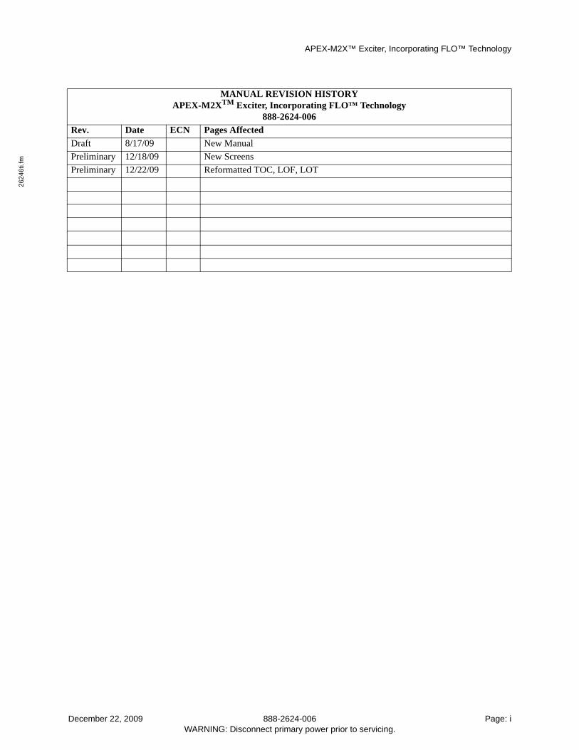
MANUAL REVISION HISTORYAPEX-M2XTM Exciter, Incorporating FLO™ Technology
888-2624-006
Rev. Date ECN Pages Affected
Draft 8/17/09 New Manual
Preliminary 12/18/09 New Screens
Preliminary 12/22/09 Reformatted TOC, LOF, LOT
December 22, 2009 888-2624-006 Page: iWARNING: Disconnect primary power prior to servicing.
APEX-M2X™ Exciter, Incorporating FLO™ Technology
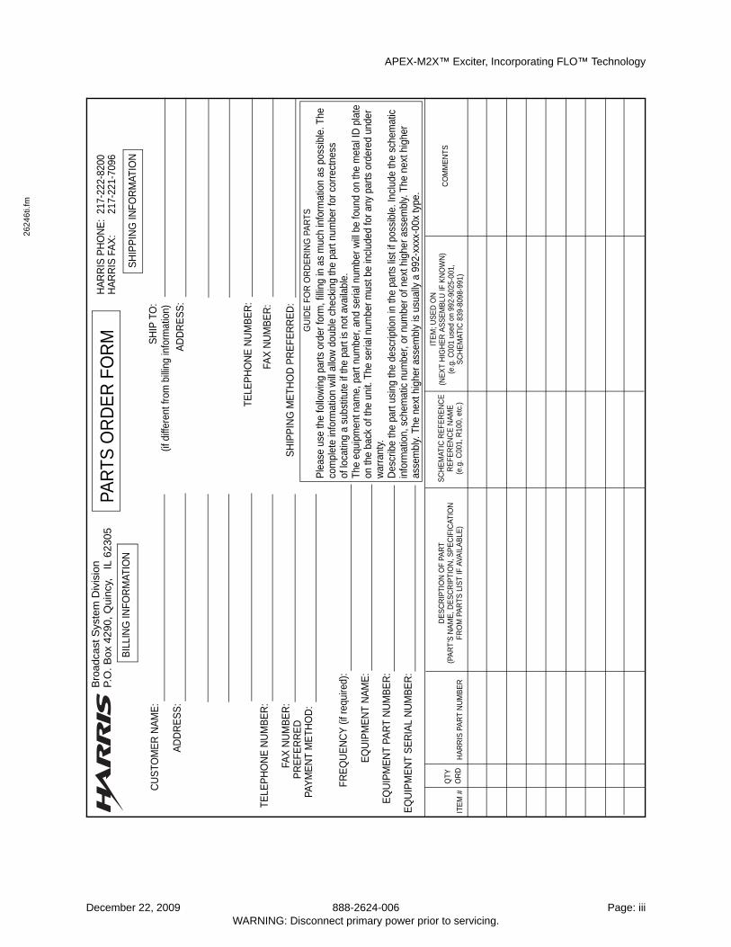
Guide to Using Harris Parts List Information
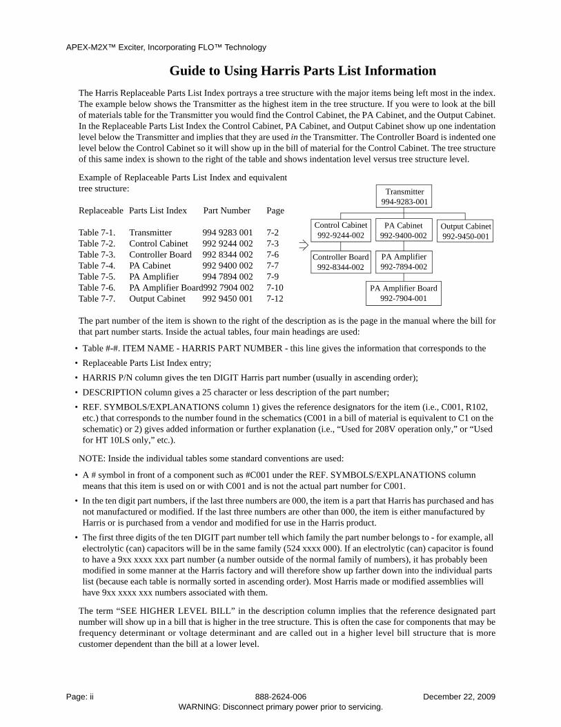
The Harris Replaceable Parts List Index portrays a tree structure with the major items being left most in the index.The example below shows the Transmitter as the highest item in the tree structure. If you were to look at the billof materials table for the Transmitter you would find the Control Cabinet, the PA Cabinet, and the Output Cabinet.In the Replaceable Parts List Index the Control Cabinet, PA Cabinet, and Output Cabinet show up one indentationlevel below the Transmitter and implies that they are used in the Transmitter. The Controller Board is indented onelevel below the Control Cabinet so it will show up in the bill of material for the Control Cabinet. The tree structureof this same index is shown to the right of the table and shows indentation level versus tree structure level.
Example of Replaceable Parts List Index and equivalenttree structure:
Replaceable Parts List Index Part Number Page
Table 7-1. Transmitter 994 9283 001 7-2Table 7-2. Control Cabinet 992 9244 002 7-3Table 7-3. Controller Board 992 8344 002 7-6Table 7-4. PA Cabinet 992 9400 002 7-7Table 7-5. PA Amplifier 994 7894 002 7-9Table 7-6. PA Amplifier Board992 7904 002 7-10Table 7-7. Output Cabinet 992 9450 001 7-12
The part number of the item is shown to the right of the description as is the page in the manual where the bill forthat part number starts. Inside the actual tables, four main headings are used:
• Table #-#. ITEM NAME - HARRIS PART NUMBER - this line gives the information that corresponds to the
• Replaceable Parts List Index entry;
• HARRIS P/N column gives the ten DIGIT Harris part number (usually in ascending order);
• DESCRIPTION column gives a 25 character or less description of the part number;
• REF. SYMBOLS/EXPLANATIONS column 1) gives the reference designators for the item (i.e., C001, R102, etc.) that corresponds to the number found in the schematics (C001 in a bill of material is equivalent to C1 on the schematic) or 2) gives added information or further explanation (i.e., “Used for 208V operation only,” or “Used for HT 10LS only,” etc.).
NOTE: Inside the individual tables some standard conventions are used:
• A # symbol in front of a component such as #C001 under the REF. SYMBOLS/EXPLANATIONS column means that this item is used on or with C001 and is not the actual part number for C001.
• In the ten digit part numbers, if the last three numbers are 000, the item is a part that Harris has purchased and has not manufactured or modified. If the last three numbers are other than 000, the item is either manufactured by Harris or is purchased from a vendor and modified for use in the Harris product.
• The first three digits of the ten DIGIT part number tell which family the part number belongs to - for example, all electrolytic (can) capacitors will be in the same family (524 xxxx 000). If an electrolytic (can) capacitor is found to have a 9xx xxxx xxx part number (a number outside of the normal family of numbers), it has probably been modified in some manner at the Harris factory and will therefore show up farther down into the individual parts list (because each table is normally sorted in ascending order). Most Harris made or modified assemblies will have 9xx xxxx xxx numbers associated with them.
The term “SEE HIGHER LEVEL BILL” in the description column implies that the reference designated partnumber will show up in a bill that is higher in the tree structure. This is often the case for components that may befrequency determinant or voltage determinant and are called out in a higher level bill structure that is morecustomer dependent than the bill at a lower level.
Control Cabinet992-9244-002
Controller Board992-8344-002
Output Cabinet992-9450-001
Transmitter994-9283-001
PA Cabinet992-9400-002
PA Amplifier992-7894-002
PA Amplifier Board992-7904-001
Page: ii 888-2624-006 December 22, 2009WARNING: Disconnect primary power prior to servicing.
APEX-M2X™ Exciter, Incorporating FLO™ Technology
262
46
ti.fm
Bro
adca
st S
yste
m D
ivis
ion
P.O
. B
ox
4290
, Qui
ncy
, I
L 623
05
BIL
LIN
G IN
FOR
MAT
ION
CU
STO
ME
R N
AM
E:
AD
DR
ES
S:
TELE
PH
ON
E N
UM
BE
R:
FAX
NU
MB
ER
:P
RE
FER
RE
DPA
YM
EN
T M
ETH
OD
:
FRE
QU
EN
CY
(if r
equi
red)
:
EQ
UIP
ME
NT
NA
ME
:
EQ
UIP
ME
NT
PAR
T N
UM
BE
R:
EQ
UIP
ME
NT
SE
RIA
L N
UM
BE
R:
ITE
M #
QTY
OR
DH
AR
RIS
PA
RT
NU
MB
ER
DE
SC
RIP
TIO
N O
F PA
RT
(PA
RT’
S N
AM
E, D
ES
CR
IPTI
ON
, SP
EC
IFIC
ATIO
NFR
OM
PA
RTS
LIS
T IF
AVA
ILA
BLE
)
SC
HE
MAT
IC R
EFE
RE
NC
ER
EFE
RE
NC
E N
AM
E(e
.g. C
001,
R10
0, e
tc.)
ITE
M; U
SE
D O
N(N
EX
T H
IGH
ER
AS
SE
MB
LU IF
KN
OW
N)
(e.g
. C00
1 us
ed o
n 99
2-90
25-0
01,
SC
HE
MAT
IC 8
39-8
098-
991)
CO
MM
EN
TS
GU
IDE
FO
R O
RD
ER
ING
PA
RTS
Ple
ase
use
the
follo
win
g pa
rts o
rder
form
, fill
ing
in a
s m
uch
info
rmat
ion
as p
ossi
ble.
The
PAR
TS O
RD
ER
FO
RM
HA
RR
IS P
HO
NE
: 21
7-22
2-82
00H
AR
RIS
FA
X:
217-
221-
7096
SH
IPP
ING
INFO
RM
ATIO
N
SH
IP T
O:
(if d
iffer
ent f
rom
bill
ing
info
rmat
ion)
AD
DR
ES
S:
TELE
PH
ON
E N
UM
BE
R:
FAX
NU
MB
ER
:
SH
IPP
ING
ME
THO
D P
RE
FER
RE
D:
com
plet
e in
form
atio
n w
ill a
llow
dou
ble
chec
king
the
part
num
ber f
or c
orre
ctne
ssof
loca
ting
a su
bstit
ute
if th
e pa
rt is
not
ava
ilabl
e.Th
e eq
uipm
ent n
ame,
par
t num
ber,
and
seria
l num
ber w
ill b
e fo
und
on th
e m
etal
ID p
late
on th
e ba
ck o
f the
uni
t. Th
e se
rial n
umbe
r mus
t be
incl
uded
for a
ny p
arts
ord
ered
und
erw
arra
nty.
Des
crib
e th
e pa
rt us
ing
the
desc
riptio
n in
the
parts
list
if p
ossi
ble.
Incl
ude
the
sche
mat
icin
form
atio
n, s
chem
atic
num
ber,
or n
umbe
r of n
ext h
ighe
r ass
embl
y. T
he n
ext h
ighe
ras
sem
bly.
The
nex
t hig
her a
ssem
bly
is u
sual
ly a
992
-xxx
x-00
x ty
pe.
December 22, 2009 888-2624-006 Page: iiiWARNING: Disconnect primary power prior to servicing.
APEX-M2X™ Exciter, Incorporating FLO™ Technology
WARNINGThe currents and voltages in this equipment are dangerous. Person-nel must at all times observe safety warnings, instructions and regu-lations.
This manual is intended as a general guide for trained and qualified personnel who areaware of the dangers inherent in handling potentially hazardous electrical/electroniccircuits. It is not intended to contain a complete statement of all safety precautions whichshould be observed by personnel in using this or other electronic equipment.
The installation, operation, maintenance and service of this equipment involves risks bothto personnel and equipment, and must be performed only by qualified personnel exercisingdue care. HARRIS CORPORATION shall not be responsible for injury or damageresulting from improper procedures or from the use of improperly trained or inexperiencedpersonnel performing such tasks.
During installation and operation of this equipment, local building codes and fire protec-tion standards must be observed. The following National Fire Protection Association(NFPA) standards are recommended as reference:
• Automatic Fire Detectors, No. 72E
• Installation, Maintenance, and Use of Portable Fire Extinguishers, No. 10
• Halogenated Fire Extinguishing Agent Systems, No. 12A
WARNINGAlways disconnect power before opening covers, doors, enclosures,gates, panels or shields. Always use grounding sticks and short outhigh voltage points before servicing. Never make internal adjust-ments, perform maintenance or service when alone or when fa-tigued.
Do not remove, short-circuit or tamper with interlock switches on access covers, doors,enclosures, gates, panels or shields. Keep away from live circuits, know your equipmentand don’t take chances.
WARNINGIn case of emergency ensure that power has been disconnected.
If oil filled or electrolytic capacitors are utilized in your equipment, and if a leak or bulgeis apparent on the capacitor case when the unit is opened for service or maintenance, allowthe unit to cool down before attempting to remove the defective capacitor. Do not attemptto service a defective capacitor while it is hot due to the possibility of a case rupture andsubsequent injury.
Page: iv 888-2624-006 December 22, 2009WARNING: Disconnect primary power prior to servicing.
APEX-M2X™ Exciter, Incorporating FLO™ Technology
262
46
ti.fm
December 22, 2009 888-2624-006 Page: vWARNING: Disconnect primary power prior to servicing.
APEX-M2X™ Exciter, Incorporating FLO™ Technology
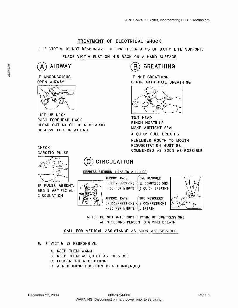
FIRST-AID
Personnel engaged in the installation, operation, maintenance or servicing of thisequipment are urged to become familiar with first-aid theory and practices. The followinginformation is not intended to be complete first-aid procedures, it is a brief and is only tobe used as a reference. It is the duty of all personnel using the equipment to be prepared togive adequate Emergency First Aid and thereby prevent avoidable loss of life.
Treatment of Electrical Burns
1. Extensive burned and broken skin
A. Cover area with clean sheet or cloth. (Cleanest available cloth article.)
B. Do not break blisters, remove tissue, remove adhered particles of clothing, or apply any salve or ointment.
C. Treat victim for shock as required.
D. Arrange transportation to a hospital as quickly as possible.
E. If arms or legs are affected keep them elevated.
NOTEIf medical help will not be available within an hour and the victimis conscious and not vomiting, give him a weak solution of salt andsoda: 1 level teaspoonful of salt and 1/2 level teaspoonful of bakingsoda to each quart of water (neither hot or cold). Allow victim to sipslowly about 4 ounces (a half of glass) over a period of 15 minutes.Discontinue fluid if vomiting occurs. (Do not give alcohol.)
2. Less severe burns - (1st & 2nd degree)
A. Apply cool (not ice cold) compresses using the cleanest available cloth arti-cle.
B. Do not break blisters, remove tissue, remove adhered particles of clothing, or apply salve or ointment.
C. Apply clean dry dressing if necessary.
D. Treat victim for shock as required.
E. Arrange transportation to a hospital as quickly as possible.
F. If arms or legs are affected keep them elevated.
REFERENCE
ILLINOIS HEART ASSOCIATION
AMERICAN RED CROSS STANDARD FIRST AID AND PERSONAL SAFETYMANUAL (SECOND EDITION)
Page: vi 888-2624-006 December 22, 2009WARNING: Disconnect primary power prior to servicing.
APEX-M2X™ Exciter, Incorporating FLO™ TechnologyTable of Contents
26
246
s10
0TO
C.fm
Table of Contents1 Introduction . . . . . . . . . . . . . . . . . . . . . . . . . . . . . . . . . . . . . . . . . . . . . . . . . . . 1-1
1.1 APEX-M2X Exciter Quick Start Guide . . . . . . . . . . . . . . . . . . . . . . . . . 1-1
1.2 Organization of Technical Manual . . . . . . . . . . . . . . . . . . . . . . . . . . . 1-1
1.3 General Description . . . . . . . . . . . . . . . . . . . . . . . . . . . . . . . . . 1-1
1.4 Physical Description . . . . . . . . . . . . . . . . . . . . . . . . . . . . . . . . . 1-1
1.5 Technical Overview . . . . . . . . . . . . . . . . . . . . . . . . . . . . . . . . . 1-3
1.6 APEX-M2X System and Modulation Standards . . . . . . . . . . . . . . . . . . . . . . 1-4
1.7 APEX-M2X Exciter Specifications . . . . . . . . . . . . . . . . . . . . . . . . . . . 1-5
1.7.1 Transmitter I/O Board Option Connectors . . . . . . . . . . . . . . . . . . . . . . . . . . . 1-7
1.7.1.1 Bottom Rear Panel, UHF Transmitter Interface Connector . . . . . . . . . . . . 1-7
1.7.1.2 Top Rear Panel, User Remote Connector . . . . . . . . . . . . . . . . . . . . . 1-8
1.7.1.3 VHF to UHF Transmitter Interface Adaptor Cable . . . . . . . . . . . . . . . . 1-9
2 Connecting To The APEX-M2X Exciter . . . . . . . . . . . . . . . . . . . . . . . . . . . . . . . . . . . . 2-1
2.1 APEX-M2X Exciter Quick Start Guide . . . . . . . . . . . . . . . . . . . . . . . . . 2-1
2.2 Introduction . . . . . . . . . . . . . . . . . . . . . . . . . . . . . . . . . . . . 2-1
2.3 Uses For The Exciter Front and Rear RJ45 Connectors . . . . . . . . . . . . . . . . . . . 2-1
2.4 Exciter Log In Authorization Levels . . . . . . . . . . . . . . . . . . . . . . . . . . 2-2
2.5 Changing the User Name and Password . . . . . . . . . . . . . . . . . . . . . . . . . 2-2
2.6 Connection Through The Exciter Front Ethernet Connector . . . . . . . . . . . . . . . . . 2-3
2.6.1 Obtaining Address With Computer in DHCP Client Mode . . . . . . . . . . . . . . . . . . 2-3
2.6.1.1 Obtaining A Computer Address Without Rebooting . . . . . . . . . . . . . . . 2-3
2.6.2 Making the Connection to the Exciter . . . . . . . . . . . . . . . . . . . . . . . . . . . . . 2-4
2.6.3 Obtaining Exciter Rear Ethernet Connector Address . . . . . . . . . . . . . . . . . . . . . 2-4
2.7 Connecting Via The Exciter Rear Panel Ethernet Connector . . . . . . . . . . . . . . . . . 2-4
2.7.1 Connecting To The Exciter Through An Existing Ethernet Network . . . . . . . . . . . . . 2-5
2.7.2 Direct Connection, Computer To Exciter Rear Ethernet Connector . . . . . . . . . . . . . . 2-5
2.8 Exciter Ethernet Address For Transmitters Using eCDi. . . . . . . . . . . . . . . . . . . . 2-5
2.9 Changing Computer Operating Mode Between Static and DHCP . . . . . . . . . . . . . . . 2-6
2.9.1 Verifying The Computer IP Address. . . . . . . . . . . . . . . . . . . . . . . . . . . . . . 2-6
2.10 Exciter Screen Captures . . . . . . . . . . . . . . . . . . . . . . . . . . . . . . . 2-7
2.11 Software Downloads . . . . . . . . . . . . . . . . . . . . . . . . . . . . . . . . . 2-7
2.12 Ethernet Connection Via Tera Term. . . . . . . . . . . . . . . . . . . . . . . . . . 2-11
2.13 Ethernet Connection Via HyperTerminal . . . . . . . . . . . . . . . . . . . . . . . . 2-13
3 Operating the APEX-M2X Exciter, FLO Mode . . . . . . . . . . . . . . . . . . . . . . . . . . . . . . . . . 3-1
3.1 GUI Screen Selections Within This Chapter . . . . . . . . . . . . . . . . . . . . . . . 3-1
12/22/09 888-2624-006 Page: viiWARNING: Disconnect primary power prior to servicing.
APEX-M2X™ Exciter, Incorporating FLO™ TechnologyTable of Contents
3.2 Basic Operating Procedure, Ethernet Connection. . . . . . . . . . . . . . . . . . . . . . 3-3
3.3 Home Screen . . . . . . . . . . . . . . . . . . . . . . . . . . . . . . . . . . . . 3-3
3.3.1 Performance . . . . . . . . . . . . . . . . . . . . . . . . . . . . . . . . . . . . . . . . . . 3-3
3.3.2 Raising or Lowering Output Power . . . . . . . . . . . . . . . . . . . . . . . . . . . . . . 3-4
3.3.3 Exciter Status Sub Window . . . . . . . . . . . . . . . . . . . . . . . . . . . . . . . . . . 3-4
3.3.4 System Output Sub Window . . . . . . . . . . . . . . . . . . . . . . . . . . . . . . . . . . 3-4
3.3.5 RTAC Status Sub Window. . . . . . . . . . . . . . . . . . . . . . . . . . . . . . . . . . . 3-4
3.3.6 Setup Soft Key . . . . . . . . . . . . . . . . . . . . . . . . . . . . . . . . . . . . . . . . . 3-5
3.3.7 Status Soft Key . . . . . . . . . . . . . . . . . . . . . . . . . . . . . . . . . . . . . . . . . 3-5
3.3.8 Fault Log Soft Key . . . . . . . . . . . . . . . . . . . . . . . . . . . . . . . . . . . . . . . 3-5
3.3.9 ISP Soft Key . . . . . . . . . . . . . . . . . . . . . . . . . . . . . . . . . . . . . . . . . . 3-5
3.3.10 Upload Config . . . . . . . . . . . . . . . . . . . . . . . . . . . . . . . . . . . . . . . . . 3-5
3.3.10.1 Saving Exciter Configuration to a FIle. . . . . . . . . . . . . . . . . . . . . . . 3-5
3.3.10.2 Restoring Exciter Configuration From a File. . . . . . . . . . . . . . . . . . . . 3-6
3.4 Flow Chart For Home Screen . . . . . . . . . . . . . . . . . . . . . . . . . . . . . 3-9
3.5 RTAC Setup Screen . . . . . . . . . . . . . . . . . . . . . . . . . . . . . . . . 3-10
3.5.1 RTAC Setup Sub Windows . . . . . . . . . . . . . . . . . . . . . . . . . . . . . . . . . . 3-10
3.5.2 Store Navigation Soft Key . . . . . . . . . . . . . . . . . . . . . . . . . . . . . . . . . . . 3-11
3.6 Setup Navigation Screen . . . . . . . . . . . . . . . . . . . . . . . . . . . . . . 3-11
3.6.1 Setup Navigation FLow Chart . . . . . . . . . . . . . . . . . . . . . . . . . . . . . . . . . 3-12
3.7 System Setup Screen. . . . . . . . . . . . . . . . . . . . . . . . . . . . . . . . 3-13
3.7.1 System Time Adjustment . . . . . . . . . . . . . . . . . . . . . . . . . . . . . . . . . . . 3-13
3.7.2 Page Title . . . . . . . . . . . . . . . . . . . . . . . . . . . . . . . . . . . . . . . . . . . . 3-13
3.7.3 Feature Key. . . . . . . . . . . . . . . . . . . . . . . . . . . . . . . . . . . . . . . . . . . 3-13
3.7.4 Transmitter Type . . . . . . . . . . . . . . . . . . . . . . . . . . . . . . . . . . . . . . . . 3-14
3.8 RTAC Setup Screen 1, Special Modes And RTAC Profiles . . . . . . . . . . . . . . . . 3-15
3.8.1 Special RTAC Modes Screen . . . . . . . . . . . . . . . . . . . . . . . . . . . . . . . . . 3-15
3.8.1.1 Power On Linear Mode . . . . . . . . . . . . . . . . . . . . . . . . . . . . . . 3-15
3.8.1.2 Power On Nonlinear Mode. . . . . . . . . . . . . . . . . . . . . . . . . . . . . 3-15
3.8.2 RTAC Profiles . . . . . . . . . . . . . . . . . . . . . . . . . . . . . . . . . . . . . . . . . 3-16
3.9 RTAC Setup Screen 2, Stored Correction Sets. . . . . . . . . . . . . . . . . . . . . . 3-17
3.9.1 Stored Correction Sets Window . . . . . . . . . . . . . . . . . . . . . . . . . . . . . . . . 3-17
3.9.1.1 Operate RTAC From A Saved Filter Set. . . . . . . . . . . . . . . . . . . . . . 3-18
3.10 RTAC Setup Screen 3 . . . . . . . . . . . . . . . . . . . . . . . . . . . . . . . 3-19
3.10.1 Peak Reduction Sub Window . . . . . . . . . . . . . . . . . . . . . . . . . . . . . . . . . 3-19
3.10.1.1 Nonlinear Correction Range . . . . . . . . . . . . . . . . . . . . . . . . . . . . 3-19
Page: viii 888-2624-006 12/22/09WARNING: Disconnect primary power prior to servicing.
APEX-M2X™ Exciter, Incorporating FLO™ TechnologyTable of Contents
26
246
s10
0TO
C.fm
3.10.1.2 Maximum Crest Factor . . . . . . . . . . . . . . . . . . . . . . . . . . . . . . . 3-20
3.10.1.3 Input Channel Filter . . . . . . . . . . . . . . . . . . . . . . . . . . . . . . . . 3-21
3.11 FLO Setup Screen 1 . . . . . . . . . . . . . . . . . . . . . . . . . . . . . . . . 3-22
3.11.1 Cmds (Commands) Soft Key. . . . . . . . . . . . . . . . . . . . . . . . . . . . . . . . . . 3-22
3.11.2 SFN Sub window. . . . . . . . . . . . . . . . . . . . . . . . . . . . . . . . . . . . . . . . 3-22
3.11.3 Transport Stream Sub Window . . . . . . . . . . . . . . . . . . . . . . . . . . . . . . . . 3-23
3.12 FLO Setup Screen 2 . . . . . . . . . . . . . . . . . . . . . . . . . . . . . . . . 3-23
3.12.1 Transmitter ID Parameters Sub Window. . . . . . . . . . . . . . . . . . . . . . . . . . . . 3-23
3.13 FLO Setup Screen 3 . . . . . . . . . . . . . . . . . . . . . . . . . . . . . . . . 3-24
3.13.1 Delays Sub Window . . . . . . . . . . . . . . . . . . . . . . . . . . . . . . . . . . . . . . 3-25
3.13.2 LOI Insertion Sub Window . . . . . . . . . . . . . . . . . . . . . . . . . . . . . . . . . . 3-26
3.14 FLO Setup Screen 4 . . . . . . . . . . . . . . . . . . . . . . . . . . . . . . . . 3-27
3.14.1 Wide Area PID . . . . . . . . . . . . . . . . . . . . . . . . . . . . . . . . . . . . . . . . . 3-27
3.14.2 Local Area PID. . . . . . . . . . . . . . . . . . . . . . . . . . . . . . . . . . . . . . . . . 3-27
3.15 FLO Setup Screen 5 . . . . . . . . . . . . . . . . . . . . . . . . . . . . . . . . 3-28
3.15.1 Modulator Parameters Sub Window . . . . . . . . . . . . . . . . . . . . . . . . . . . . . . 3-28
3.16 FLO Setup Screen 6 . . . . . . . . . . . . . . . . . . . . . . . . . . . . . . . . 3-29
3.16.1 Modulator Parameters Sub Window . . . . . . . . . . . . . . . . . . . . . . . . . . . . . . 3-29
3.16.2 Test Modes Sub Window . . . . . . . . . . . . . . . . . . . . . . . . . . . . . . . . . . . 3-29
3.17 FLO Setup Commands . . . . . . . . . . . . . . . . . . . . . . . . . . . . . . . 3-30
3.18 Output Setup Screen . . . . . . . . . . . . . . . . . . . . . . . . . . . . . . . . 3-31
3.19 PFRU Setup Screen . . . . . . . . . . . . . . . . . . . . . . . . . . . . . . . . 3-32
3.19.0.1 Setting RF Output and Offset Frequencies. . . . . . . . . . . . . . . . . . . . . 3-32
3.19.1 10 MHz OCXO Reference Sub Window. . . . . . . . . . . . . . . . . . . . . . . . . . . . 3-33
3.20 Transmitter I/O Screen . . . . . . . . . . . . . . . . . . . . . . . . . . . . . . . 3-34
3.20.1 Transport Stream Active Monitor Output Sub Window . . . . . . . . . . . . . . . . . . . . 3-34
3.20.2 Foldback Setup Sub Window . . . . . . . . . . . . . . . . . . . . . . . . . . . . . . . . . 3-34
3.20.2.1 F/B Low Thresh . . . . . . . . . . . . . . . . . . . . . . . . . . . . . . . . . . 3-35
3.20.2.2 F/B High Thresh . . . . . . . . . . . . . . . . . . . . . . . . . . . . . . . . . . 3-35
3.20.2.3 Max F/B Level . . . . . . . . . . . . . . . . . . . . . . . . . . . . . . . . . . . 3-35
3.20.3 RF Cutoff Sub Window . . . . . . . . . . . . . . . . . . . . . . . . . . . . . . . . . . . . 3-35
3.21 Remote Communications Setup Screen 1, Ethernet . . . . . . . . . . . . . . . . . . . . 3-36
3.21.1 Rear Ethernet Port . . . . . . . . . . . . . . . . . . . . . . . . . . . . . . . . . . . . . . . 3-36
3.21.2 Front Ethernet Connector . . . . . . . . . . . . . . . . . . . . . . . . . . . . . . . . . . . 3-37
3.22 Remote Communications Setup Screen 2, RS232 and CAN . . . . . . . . . . . . . . . . 3-37
3.22.1 RS232 Setup . . . . . . . . . . . . . . . . . . . . . . . . . . . . . . . . . . . . . . . . . . 3-37
12/22/09 888-2624-006 Page: ixWARNING: Disconnect primary power prior to servicing.
APEX-M2X™ Exciter, Incorporating FLO™ TechnologyTable of Contents
3.22.2 CAN Bus Setup . . . . . . . . . . . . . . . . . . . . . . . . . . . . . . . . . . . . . . . . 3-38
3.23 Remote Communications Setup Screen 3, SNMP . . . . . . . . . . . . . . . . . . . . 3-38
3.23.1 SNMP Setup . . . . . . . . . . . . . . . . . . . . . . . . . . . . . . . . . . . . . . . . . . 3-39
3.23.2 Lower Half of the SNMP Setup Screen . . . . . . . . . . . . . . . . . . . . . . . . . . . . 3-39
3.24 Test (Pattern) Setup Screen . . . . . . . . . . . . . . . . . . . . . . . . . . . . . 3-39
3.25 Status Navigation Screen . . . . . . . . . . . . . . . . . . . . . . . . . . . . . . 3-40
3.25.1 Status Negation Flow Chart . . . . . . . . . . . . . . . . . . . . . . . . . . . . . . . . . . 3-41
3.26 Signal Processor Status Screen 1 . . . . . . . . . . . . . . . . . . . . . . . . . . . 3-42
3.26.1 Signal Processor Statuses . . . . . . . . . . . . . . . . . . . . . . . . . . . . . . . . . . . 3-42
3.27 Signal Processor Status Screen 2 . . . . . . . . . . . . . . . . . . . . . . . . . . . 3-43
3.27.1 Temperature (Signal Processor Degrees C) Sub Window . . . . . . . . . . . . . . . . . . . 3-43
3.27.2 Power Supply (Voltage Reading) Sub Window . . . . . . . . . . . . . . . . . . . . . . . . 3-44
3.27.3 Fans Status Sub Window. . . . . . . . . . . . . . . . . . . . . . . . . . . . . . . . . . . . 3-44
3.28 FLO (Modulator) Status Screen 1 . . . . . . . . . . . . . . . . . . . . . . . . . . . 3-44
3.28.1 Summary Sub Window. . . . . . . . . . . . . . . . . . . . . . . . . . . . . . . . . . . . . 3-45
3.28.2 MTI Sub Window . . . . . . . . . . . . . . . . . . . . . . . . . . . . . . . . . . . . . . . 3-45
3.29 FLO (Modulator) Status Screen 2 . . . . . . . . . . . . . . . . . . . . . . . . . . . 3-46
3.29.1 Transport Stream Sub Window . . . . . . . . . . . . . . . . . . . . . . . . . . . . . . . . 3-46
3.29.2 ASI 1 and ASI 2 Sub Windows . . . . . . . . . . . . . . . . . . . . . . . . . . . . . . . . 3-47
3.29.3 Wide Packet Rates . . . . . . . . . . . . . . . . . . . . . . . . . . . . . . . . . . . . . . . 3-47
3.29.4 Local Packet Rates . . . . . . . . . . . . . . . . . . . . . . . . . . . . . . . . . . . . . . . 3-47
3.30 FLO (Modulator) Status Screen 3 . . . . . . . . . . . . . . . . . . . . . . . . . . . 3-48
3.30.0.1 Timing Status, GPS & Clock Status Functions . . . . . . . . . . . . . . . . . . 3-48
3.30.1 SFN Buffer . . . . . . . . . . . . . . . . . . . . . . . . . . . . . . . . . . . . . . . . . . . 3-49
3.31 RTAC Status Screen, Down Converter. . . . . . . . . . . . . . . . . . . . . . . . . 3-50
3.31.1 Levels (RTAC RF Samples) Sub Window. . . . . . . . . . . . . . . . . . . . . . . . . . . 3-50
3.31.2 Mode (Down Converter Switch Mode) . . . . . . . . . . . . . . . . . . . . . . . . . . . . 3-51
3.31.3 Down Converter Attenuation Sub Window . . . . . . . . . . . . . . . . . . . . . . . . . . 3-51
3.32 Output Status Screen, Up Converter . . . . . . . . . . . . . . . . . . . . . . . . . . 3-51
3.32.1 Status Sub Window . . . . . . . . . . . . . . . . . . . . . . . . . . . . . . . . . . . . . . 3-52
3.32.2 Levels (mV) . . . . . . . . . . . . . . . . . . . . . . . . . . . . . . . . . . . . . . . . . . 3-52
3.32.3 Temperature (C) . . . . . . . . . . . . . . . . . . . . . . . . . . . . . . . . . . . . . . . . 3-52
3.32.4 Power Supply (VDC). . . . . . . . . . . . . . . . . . . . . . . . . . . . . . . . . . . . . . 3-52
3.32.5 Up Converter Attenuation . . . . . . . . . . . . . . . . . . . . . . . . . . . . . . . . . . . 3-52
3.33 Transmitter I/O Status Screen . . . . . . . . . . . . . . . . . . . . . . . . . . . . 3-53
3.33.1 Status . . . . . . . . . . . . . . . . . . . . . . . . . . . . . . . . . . . . . . . . . . . . . . 3-53
Page: x 888-2624-006 12/22/09WARNING: Disconnect primary power prior to servicing.
APEX-M2X™ Exciter, Incorporating FLO™ TechnologyTable of Contents
26
246
s10
0TO
C.fm
3.33.2 Foldback Input Voltage . . . . . . . . . . . . . . . . . . . . . . . . . . . . . . . . . . . . 3-53
3.34 PFRU Status Screen 1 . . . . . . . . . . . . . . . . . . . . . . . . . . . . . . . 3-54
3.34.1 FPGA Sub Window . . . . . . . . . . . . . . . . . . . . . . . . . . . . . . . . . . . . . . 3-54
3.34.2 System Reference CLocks Sub Window. . . . . . . . . . . . . . . . . . . . . . . . . . . . 3-55
3.34.3 PLL Reference Clocks Sub Window. . . . . . . . . . . . . . . . . . . . . . . . . . . . . . 3-55
3.34.4 PLL Status Sub Window . . . . . . . . . . . . . . . . . . . . . . . . . . . . . . . . . . . . 3-55
3.35 PFRU Status Screen 2 . . . . . . . . . . . . . . . . . . . . . . . . . . . . . . . 3-56
3.35.1 GPS Sub Window . . . . . . . . . . . . . . . . . . . . . . . . . . . . . . . . . . . . . . . 3-56
3.35.1.1 Holdover Sub Window . . . . . . . . . . . . . . . . . . . . . . . . . . . . . . . 3-56
3.36 Battery Backup Status Screen . . . . . . . . . . . . . . . . . . . . . . . . . . . . 3-58
3.36.1 Status Sub Window . . . . . . . . . . . . . . . . . . . . . . . . . . . . . . . . . . . . . . 3-58
3.37 Revisions Screen 1 . . . . . . . . . . . . . . . . . . . . . . . . . . . . . . . . 3-59
3.38 Revisions Screen 2 . . . . . . . . . . . . . . . . . . . . . . . . . . . . . . . . 3-60
3.39 Fault Log Screen . . . . . . . . . . . . . . . . . . . . . . . . . . . . . . . . . 3-61
3.40 In Service Programming, ISP . . . . . . . . . . . . . . . . . . . . . . . . . . . . 3-62
4 APEX-M2X™ Exciter Theory of Operation . . . . . . . . . . . . . . . . . . . . . . . . . . . . . . . . . . 4-1
4.1 General Description . . . . . . . . . . . . . . . . . . . . . . . . . . . . . . . . . 4-1
4.2 Transmitter Systems Block Diagram . . . . . . . . . . . . . . . . . . . . . . . . . . 4-3
4.3 APEX-M2X Exciter Modulation Overview . . . . . . . . . . . . . . . . . . . . . . . . 4-3
4.3.1 The Modulation Process . . . . . . . . . . . . . . . . . . . . . . . . . . . . . . . . . . . . 4-4
4.3.2 RF Sample Processing . . . . . . . . . . . . . . . . . . . . . . . . . . . . . . . . . . . . . 4-4
4.4 Low Voltage Power Supply Board . . . . . . . . . . . . . . . . . . . . . . . . . . . 4-7
4.4.1 AC Input . . . . . . . . . . . . . . . . . . . . . . . . . . . . . . . . . . . . . . . . . . . . 4-7
4.4.2 LVPS . . . . . . . . . . . . . . . . . . . . . . . . . . . . . . . . . . . . . . . . . . . . . . 4-7
4.4.3 Fans. . . . . . . . . . . . . . . . . . . . . . . . . . . . . . . . . . . . . . . . . . . . . . . 4-7
4.4.4 Battery Backup . . . . . . . . . . . . . . . . . . . . . . . . . . . . . . . . . . . . . . . . . 4-8
4.5 PFRU (Precise Frequency Reference Unit) Board . . . . . . . . . . . . . . . . . . . . . 4-9
4.5.1 PFRU Board 1st LO PLL for the DAC Clock Circuit . . . . . . . . . . . . . . . . . . . . . 4-9
4.5.1.1 DAC Clock Frequencies For 140 +/- 0.5 MHz IF . . . . . . . . . . . . . . . . . 4-9
4.5.2 PFRU Board Local Oscillator-2 Circuit, For UDC . . . . . . . . . . . . . . . . . . . . . . 4-10
4.5.3 PFRU Board Reference Oscillator Circuit . . . . . . . . . . . . . . . . . . . . . . . . . . . 4-12
4.5.4 PFRU Board GPS Circuit . . . . . . . . . . . . . . . . . . . . . . . . . . . . . . . . . . . 4-12
4.6 Up/Down Converter Board . . . . . . . . . . . . . . . . . . . . . . . . . . . . . 4-13
4.6.1 Up Converter Major Specifications . . . . . . . . . . . . . . . . . . . . . . . . . . . . . . 4-13
4.6.2 Functional Description of Upconverter . . . . . . . . . . . . . . . . . . . . . . . . . . . . 4-14
4.6.3 Down Converter Major Specifications . . . . . . . . . . . . . . . . . . . . . . . . . . . . . 4-16
12/22/09 888-2624-006 Page: xiWARNING: Disconnect primary power prior to servicing.
APEX-M2X™ Exciter, Incorporating FLO™ TechnologyTable of Contents
4.6.4 Down Converter . . . . . . . . . . . . . . . . . . . . . . . . . . . . . . . . . . . . . . . . 4-16
4.6.5 LO DISTRIBUTION. . . . . . . . . . . . . . . . . . . . . . . . . . . . . . . . . . . . . . 4-17
4.6.6 UP Down Converter Board I/O Connector (J1) . . . . . . . . . . . . . . . . . . . . . . . . 4-18
4.7 Signal Processing Board Overview . . . . . . . . . . . . . . . . . . . . . . . . . . 4-19
4.7.1 ASI / SMPTE 310 Inputs / Output . . . . . . . . . . . . . . . . . . . . . . . . . . . . . . . 4-19
4.7.1.1 DAC . . . . . . . . . . . . . . . . . . . . . . . . . . . . . . . . . . . . . . . . 4-19
4.7.1.2 ADC . . . . . . . . . . . . . . . . . . . . . . . . . . . . . . . . . . . . . . . . 4-20
4.8 Analog Input Board Overview . . . . . . . . . . . . . . . . . . . . . . . . . . . . 4-20
4.9 Transmitter I/O Panel Overview . . . . . . . . . . . . . . . . . . . . . . . . . . . 4-20
4.9.1 Transmitter I/O Board . . . . . . . . . . . . . . . . . . . . . . . . . . . . . . . . . . . . . 4-20
4.9.2 Analog Input A/D . . . . . . . . . . . . . . . . . . . . . . . . . . . . . . . . . . . . . . . 4-21
4.9.3 Power Supply. . . . . . . . . . . . . . . . . . . . . . . . . . . . . . . . . . . . . . . . . . 4-21
4.9.4 VHF to UHF Transmitter Interface Adaptor Cable . . . . . . . . . . . . . . . . . . . . . . 4-21
5 Maintenance and Troubleshooting. . . . . . . . . . . . . . . . . . . . . . . . . . . . . . . . . . . . . . . . 5-1
5.1 Exciter Maintenance . . . . . . . . . . . . . . . . . . . . . . . . . . . . . . . . . 5-1
5.1.1 Cleaning . . . . . . . . . . . . . . . . . . . . . . . . . . . . . . . . . . . . . . . . . . . . 5-5
5.2 Loading Software . . . . . . . . . . . . . . . . . . . . . . . . . . . . . . . . . . 5-5
5.3 Changing Date and Time Battery . . . . . . . . . . . . . . . . . . . . . . . . . . . . 5-5
5.3.1 Setting Date and Time After Battery Replacement . . . . . . . . . . . . . . . . . . . . . . 5-5
5.3.1.1 Setting Time and Date . . . . . . . . . . . . . . . . . . . . . . . . . . . . . . . 5-6
5.4 Technical Assistance. . . . . . . . . . . . . . . . . . . . . . . . . . . . . . . . . 5-7
6 Parts List . . . . . . . . . . . . . . . . . . . . . . . . . . . . . . . . . . . . . . . . . . . . . . . . . . . . . 6-1
Appendix A APEX-M2X Exciter Quick Start Guide . . . . . . . . . . . . . . . . . . . . . . . . . . . . . . . . A-1
A.1 Introduction . . . . . . . . . . . . . . . . . . . . . . . . . . . . . . . . . . . A-1
A.2 Retrofit Kits For APEX-M2X Exciters. . . . . . . . . . . . . . . . . . . . . . . . . A-1
A.2.1 CD-1A to APEX-M2X Exciter Retrofits. . . . . . . . . . . . . . . . . . . . . . . . . . . . A-1
A.2.2 APEX-M2X Exciter Retrofit in a Ranger Transmitter . . . . . . . . . . . . . . . . . . . . . A-1
A.2.3 Classic APEX to APEX-M2X Exciter Retrofits . . . . . . . . . . . . . . . . . . . . . . . . A-2
A.3 UPS Option . . . . . . . . . . . . . . . . . . . . . . . . . . . . . . . . . . . A-2
A.4 Installing Date and Time Battery, Start of the Bench Test . . . . . . . . . . . . . . . . . A-2
A.5 Initial Ethernet Connection to the APEX-M2X Exciter, Bench Test Continued . . . . . . . . . A-4
A.5.1 Connection Through The Exciter Front Ethernet Connector . . . . . . . . . . . . . . . . . A-4
A.5.1.1 Obtaining Exciter Rear Ethernet Connector Address . . . . . . . . . . . . . . . A-4
A.5.2 Connecting To The Exciter Through An Existing Ethernet Network . . . . . . . . . . . . . A-5
A.6 Initial APEX Exciter Programming, Bench Test Continued . . . . . . . . . . . . . . . . A-5
A.6.1 Setting RF Output and Offset Frequencies. . . . . . . . . . . . . . . . . . . . . . . . . . . A-5
Page: xii 888-2624-006 12/22/09WARNING: Disconnect primary power prior to servicing.
APEX-M2X™ Exciter, Incorporating FLO™ TechnologyTable of Contents
26
246
s10
0TO
C.fm
A.6.2 PFRU (Precise Frequency Reference Unit) Setup Screen . . . . . . . . . . . . . . . . . . . A-6
A.6.2.1 10 MHz OCXO Discipline Method Window . . . . . . . . . . . . . . . . . . . A-6
A.6.2.2 Unmute If OCXO Undisciplined . . . . . . . . . . . . . . . . . . . . . . . . . . A-7
A.6.3 Selecting Transmitter Type . . . . . . . . . . . . . . . . . . . . . . . . . . . . . . . . . . A-7
A.6.4 System Date and Time . . . . . . . . . . . . . . . . . . . . . . . . . . . . . . . . . . . . . A-8
A.6.5 Setting RF Output Level to Power Amplifier . . . . . . . . . . . . . . . . . . . . . . . . . A-8
A.7 Installing Exciters In Transmitters . . . . . . . . . . . . . . . . . . . . . . . . . . A-9
A.7.1 RF Sample Connections and levels . . . . . . . . . . . . . . . . . . . . . . . . . . . . . . A-9
A.7.2 Signal Connections . . . . . . . . . . . . . . . . . . . . . . . . . . . . . . . . . . . . . . A-10
A.8 Initial Transmitter Power Up With the APEX-M2X Exciter Installed. . . . . . . . . . . . . A-13
A.9 Ethernet Connection Via HyperTerminal . . . . . . . . . . . . . . . . . . . . . . . . A-15
A.10 Ethernet Connection Via Tera Term. . . . . . . . . . . . . . . . . . . . . . . . . . A-17
A.11 Changing the User Name and Password . . . . . . . . . . . . . . . . . . . . . . . . A-18
Appendix B APEX-M2X Exciter Installation . . . . . . . . . . . . . . . . . . . . . . . . . . . . . . . . . . . . B-1
B.1 Introduction . . . . . . . . . . . . . . . . . . . . . . . . . . . . . . . . . . . .B-1
B.2 Retrofit Kits For APEX-M2X Exciters. . . . . . . . . . . . . . . . . . . . . . . . . .B-1
B.2.1 CD-1A to APEX-M2X Exciter Retrofits. . . . . . . . . . . . . . . . . . . . . . . . . . . . B-1
B.2.2 APEX-M2X Exciter Retrofit in a Ranger Transmitter . . . . . . . . . . . . . . . . . . . . . B-1
B.2.3 Classic APEX to APEX-M2X Exciter Retrofits . . . . . . . . . . . . . . . . . . . . . . . . B-1
B.3 Installing Exciters Removed for Shipment . . . . . . . . . . . . . . . . . . . . . . . .B-2
B.4 Signal Connections . . . . . . . . . . . . . . . . . . . . . . . . . . . . . . . . .B-2
B.5 Retrofitting Into Existing Transmitter System . . . . . . . . . . . . . . . . . . . . . . .B-5
B.5.1 APEX- M2X Exciter Operating In Analog Mode . . . . . . . . . . . . . . . . . . . . . . . B-5
B.5.2 Feed Back Requirements . . . . . . . . . . . . . . . . . . . . . . . . . . . . . . . . . . . . B-5
B.5.2.1 Feedback Signal Quality Requirements . . . . . . . . . . . . . . . . . . . . . . B-6
B.5.3 Typical Transmitter Systems Block Diagrams. . . . . . . . . . . . . . . . . . . . . . . . . B-6
B.5.4 Retrofitting The APEX-M2A Exciter Into Generic Transmitters . . . . . . . . . . . . . . . B-7
B.5.4.1 Transmitters With One PA Cabinet and Exciter . . . . . . . . . . . . . . . . . . B-7
B.5.4.2 Transmitter With One PA Cabinet And Two Exciters . . . . . . . . . . . . . . . B-8
B.5.4.3 Transmitter With Two or More PA Cabinets . . . . . . . . . . . . . . . . . . . B-9
B.5.5 Transmitter System RF Output Power Control . . . . . . . . . . . . . . . . . . . . . . . .B-10
B.5.6 Diamond Transmitters . . . . . . . . . . . . . . . . . . . . . . . . . . . . . . . . . . . . .B-11
B.5.7 Sigma Transmitters. . . . . . . . . . . . . . . . . . . . . . . . . . . . . . . . . . . . . . .B-12
B.5.8 PowerCD Transmitters . . . . . . . . . . . . . . . . . . . . . . . . . . . . . . . . . . . . .B-14
B.6 Typical Materials Needed . . . . . . . . . . . . . . . . . . . . . . . . . . . . . . B-15
B.7 Configuring the Exciter. . . . . . . . . . . . . . . . . . . . . . . . . . . . . . . B-16
12/22/09 888-2624-006 Page: xiiiWARNING: Disconnect primary power prior to servicing.

APEX-M2X™ Exciter, Incorporating FLO™ TechnologyTable of Contents
Page: xiv 888-2624-006 12/22/09WARNING: Disconnect primary power prior to servicing.
APEX-M2X™ Exciter, Incorporating FLOTM TechnologyList of Figures
2624
6s1
00L
OF
.fm
List of FiguresFigure 1-1 APEX - M2X Exciter Rear Panel View . . . . . . . . . . . . . . . . . . . . . . . . . . . . . . . . 1-2
Figure 1-2 APEX Exciter Front Panel View. . . . . . . . . . . . . . . . . . . . . . . . . . . . . . . . . . . . 1-2
Figure 1-3 Transport Stream Input Presence Indicators and Rear Panel Input Connectors . . . . . . . . . . . . 1-3
Figure 2-1 Exciter Home Screen. . . . . . . . . . . . . . . . . . . . . . . . . . . . . . . . . . . . . . . . . . 2-8
Figure 2-2 APEX-M2X Exciter Login Screen. . . . . . . . . . . . . . . . . . . . . . . . . . . . . . . . . . . 2-8
Figure 2-3 APEX-M2X Exciter In System Programming Screen . . . . . . . . . . . . . . . . . . . . . . . . . 2-9
Figure 2-4 Choose File, Software Download Window . . . . . . . . . . . . . . . . . . . . . . . . . . . . . . 2-9
Figure 2-5 Program Sub Window From Upper Left Corner of In System Programming Screen . . . . . . . . 2-10
Figure 2-6 Software Download Finished . . . . . . . . . . . . . . . . . . . . . . . . . . . . . . . . . . . . 2-10
Figure 2-7 Ethernet VT100 Connection Login Screen . . . . . . . . . . . . . . . . . . . . . . . . . . . . . 2-12
Figure 2-8 Path To Hyperterminal . . . . . . . . . . . . . . . . . . . . . . . . . . . . . . . . . . . . . . . . 2-13
Figure 2-9 Hyperterminal New Connection Window . . . . . . . . . . . . . . . . . . . . . . . . . . . . . . 2-14
Figure 2-10 New Connection Properties Settings Window . . . . . . . . . . . . . . . . . . . . . . . . . . . . 2-15
Figure 2-11 APEX-M2X VT100 Login Screen . . . . . . . . . . . . . . . . . . . . . . . . . . . . . . . . . . 2-15
Figure 3-1 Home Screen . . . . . . . . . . . . . . . . . . . . . . . . . . . . . . . . . . . . . . . . . . . . . . 3-3
Figure 3-2 S19 File Which Contains Eprom Contents. . . . . . . . . . . . . . . . . . . . . . . . . . . . . . . 3-6
Figure 3-3 Location Of Saved Configuration File . . . . . . . . . . . . . . . . . . . . . . . . . . . . . . . . . 3-6
Figure 3-4 ISP (In Service Programming) Window . . . . . . . . . . . . . . . . . . . . . . . . . . . . . . . . 3-7
Figure 3-5 Location of Exciter Configuration FIle . . . . . . . . . . . . . . . . . . . . . . . . . . . . . . . . 3-7
Figure 3-6 Module Programming Screen . . . . . . . . . . . . . . . . . . . . . . . . . . . . . . . . . . . . . 3-8
Figure 3-7 Programming FLash EEPROM . . . . . . . . . . . . . . . . . . . . . . . . . . . . . . . . . . . . 3-8
Figure 3-8 Home Screen Flow Chart . . . . . . . . . . . . . . . . . . . . . . . . . . . . . . . . . . . . . . . 3-9
Figure 3-9 RTAC Setup Screen . . . . . . . . . . . . . . . . . . . . . . . . . . . . . . . . . . . . . . . . . 3-10
Figure 3-10 Setup Navigation Screen . . . . . . . . . . . . . . . . . . . . . . . . . . . . . . . . . . . . . . . 3-11
Figure 3-11 Setup Navigation Flow Chart . . . . . . . . . . . . . . . . . . . . . . . . . . . . . . . . . . . . 3-12
Figure 3-12 System Setup Screen . . . . . . . . . . . . . . . . . . . . . . . . . . . . . . . . . . . . . . . . . 3-13
Figure 3-13 RTAC Setup Screen 1, Special Modes and RTAC Profiles . . . . . . . . . . . . . . . . . . . . . 3-15
Figure 3-14 RTAC Setup Screen 2, Stored Correction Sets . . . . . . . . . . . . . . . . . . . . . . . . . . . 3-17
Figure 3-15 RTAC Setup Screen 3 . . . . . . . . . . . . . . . . . . . . . . . . . . . . . . . . . . . . . . . . 3-19
Figure 3-16 FLO Setup Screen 1 . . . . . . . . . . . . . . . . . . . . . . . . . . . . . . . . . . . . . . . . . 3-22
Figure 3-17 FLO Setup Screen 2 . . . . . . . . . . . . . . . . . . . . . . . . . . . . . . . . . . . . . . . . . 3-23
Figure 3-18 FLO Setup Screen 3 . . . . . . . . . . . . . . . . . . . . . . . . . . . . . . . . . . . . . . . . . 3-25
Figure 3-19 FLO Setup Screen 4 . . . . . . . . . . . . . . . . . . . . . . . . . . . . . . . . . . . . . . . . . 3-27
Figure 3-20 FLO Setup Screen 5 . . . . . . . . . . . . . . . . . . . . . . . . . . . . . . . . . . . . . . . . . 3-28
Figure 3-21 FLO Setup Screen 6 . . . . . . . . . . . . . . . . . . . . . . . . . . . . . . . . . . . . . . . . . 3-29
12/22/09 888-2624-006 Page: xvWARNING: Disconnect primary power prior to servicing.
APEX-M2X™ Exciter, Incorporating FLOTM TechnologyList of Figures
Figure 3-22 FLO Setup Screen, Commands . . . . . . . . . . . . . . . . . . . . . . . . . . . . . . . . . . . 3-30
Figure 3-23 Output Setup Screen . . . . . . . . . . . . . . . . . . . . . . . . . . . . . . . . . . . . . . . . . 3-31
Figure 3-24 PFRU Setup Screen . . . . . . . . . . . . . . . . . . . . . . . . . . . . . . . . . . . . . . . . . 3-32
Figure 3-25 Transmitter I/O Setup Screen . . . . . . . . . . . . . . . . . . . . . . . . . . . . . . . . . . . . 3-34
Figure 3-26 Remote Control Setup Screen 1, Ethernet . . . . . . . . . . . . . . . . . . . . . . . . . . . . . . 3-36
Figure 3-27 Remote Communications Setup Screen 2, RS232 and CAN . . . . . . . . . . . . . . . . . . . . 3-37
Figure 3-28 Remote Communications Setup Screen 3, SNMP . . . . . . . . . . . . . . . . . . . . . . . . . . 3-38
Figure 3-29 Test (Pattern) Setup Screen . . . . . . . . . . . . . . . . . . . . . . . . . . . . . . . . . . . . . 3-39
Figure 3-30 Status Navigation Screen. . . . . . . . . . . . . . . . . . . . . . . . . . . . . . . . . . . . . . . 3-40
Figure 3-31 Status Navigation Screen Flow Chart . . . . . . . . . . . . . . . . . . . . . . . . . . . . . . . . 3-41
Figure 3-32 Signal Processor Status Screen 1. . . . . . . . . . . . . . . . . . . . . . . . . . . . . . . . . . . 3-42
Figure 3-33 Signal Processor Status Screen 2. . . . . . . . . . . . . . . . . . . . . . . . . . . . . . . . . . . 3-43
Figure 3-34 FLO (Modulator) Status Screen 1 . . . . . . . . . . . . . . . . . . . . . . . . . . . . . . . . . . 3-44
Figure 3-35 FLO (Modulator) Status Screen 2 . . . . . . . . . . . . . . . . . . . . . . . . . . . . . . . . . . 3-46
Figure 3-36 FLO (Modulator) Status Screen 3 . . . . . . . . . . . . . . . . . . . . . . . . . . . . . . . . . . 3-48
Figure 3-37 RTAC Status Screen, Down Converter . . . . . . . . . . . . . . . . . . . . . . . . . . . . . . . 3-50
Figure 3-38 Output Status Screen, Up Converter . . . . . . . . . . . . . . . . . . . . . . . . . . . . . . . . . 3-51
Figure 3-39 Transmitter I/O Status Screen . . . . . . . . . . . . . . . . . . . . . . . . . . . . . . . . . . . . 3-53
Figure 3-40 PFRU Status Screen 1 . . . . . . . . . . . . . . . . . . . . . . . . . . . . . . . . . . . . . . . . 3-54
Figure 3-41 PFRU Status Screen 2 . . . . . . . . . . . . . . . . . . . . . . . . . . . . . . . . . . . . . . . . 3-56
Figure 3-42 Battery Backup Status Screen . . . . . . . . . . . . . . . . . . . . . . . . . . . . . . . . . . . . 3-58
Figure 3-43 Revisions Screen 1 . . . . . . . . . . . . . . . . . . . . . . . . . . . . . . . . . . . . . . . . . . 3-59
Figure 3-44 Revisions Screen 2 . . . . . . . . . . . . . . . . . . . . . . . . . . . . . . . . . . . . . . . . . . 3-60
Figure 3-45 Fault Log Screen . . . . . . . . . . . . . . . . . . . . . . . . . . . . . . . . . . . . . . . . . . . 3-61
Figure 3-46 ISP (In Service Programming) Screen . . . . . . . . . . . . . . . . . . . . . . . . . . . . . . . . 3-62
Figure 4-1 Top VIew Drawing Of APEX-M2X Exciter. . . . . . . . . . . . . . . . . . . . . . . . . . . . . . 4-2
Figure 4-2 APEX -M2X Exciter/ Transmitter - RF Interconnection Block Diagram . . . . . . . . . . . . . . . 4-3
Figure 4-3 APEX Exciter - Signal Flow Block Diagram . . . . . . . . . . . . . . . . . . . . . . . . . . . . . 4-6
Figure 4-4 Low Voltage Power Supply Block Diagram. . . . . . . . . . . . . . . . . . . . . . . . . . . . . . 4-8
Figure 4-5 Battery Backup Option Block Diagram . . . . . . . . . . . . . . . . . . . . . . . . . . . . . . . . 4-9
Figure 4-6 DAC PLL (1st LO). . . . . . . . . . . . . . . . . . . . . . . . . . . . . . . . . . . . . . . . . . 4-10
Figure 4-7 UDC Local Oscillator (2nd LO) PLL . . . . . . . . . . . . . . . . . . . . . . . . . . . . . . . . 4-12
Figure 4-8 PFRU Board 10 MHz Reference Oscillator Circuit . . . . . . . . . . . . . . . . . . . . . . . . . 4-13
Figure 4-9 Upconverter BLock Diagram . . . . . . . . . . . . . . . . . . . . . . . . . . . . . . . . . . . . 4-14
Figure 4-10 Up Down Converter Board, Downconverter Block Diagram . . . . . . . . . . . . . . . . . . . . 4-16
Figure 4-11 Up Down Converter Board, Local Oscillator Distribution Circuit Block Diagram . . . . . . . . . 4-17
Page: xvi 888-2624-006 12/22/09WARNING: Disconnect primary power prior to servicing.
APEX-M2X™ Exciter, Incorporating FLOTM TechnologyList of Figures
2624
6s1
00L
OF
.fm
Figure 4-12 Transmitter I/O Board Block Diagram. . . . . . . . . . . . . . . . . . . . . . . . . . . . . . . . 4-21
Figure 5-1 View of Front Panel With Door Open . . . . . . . . . . . . . . . . . . . . . . . . . . . . . . . . . 5-1
Figure 5-2 View of Front Panel With Front Cover Removed . . . . . . . . . . . . . . . . . . . . . . . . . . . 5-1
Figure 5-3 Expanded View of Front Panel With Door Open . . . . . . . . . . . . . . . . . . . . . . . . . . . 5-2
Figure 5-4 Top View of Exciter Showing Interconnection RF and Ribbon Cables . . . . . . . . . . . . . . . . 5-3
Figure 5-5 Top and Rear Inside View Showing Transport Stream Connections . . . . . . . . . . . . . . . . . 5-4
Figure 5-6 APEX - M2X Exciter Rear Panel View . . . . . . . . . . . . . . . . . . . . . . . . . . . . . . . . 5-4
Figure 5-7 Top VIew of Rear Half of Exciter Showing Date and Time Battery Location . . . . . . . . . . . . 5-6
Figure 5-8 Date and Time Battery Location . . . . . . . . . . . . . . . . . . . . . . . . . . . . . . . . . . . . 5-7
Figure 5-9 Date and Time Battery Removal and Insertion . . . . . . . . . . . . . . . . . . . . . . . . . . . . 5-7
Figure A-1 Date and Time Battery Location . . . . . . . . . . . . . . . . . . . . . . . . . . . . . . . . . . . . A-3
Figure A-2 PFRU Setup Screen . . . . . . . . . . . . . . . . . . . . . . . . . . . . . . . . . . . . . . . . . . A-6
Figure A-3 System Setup screen . . . . . . . . . . . . . . . . . . . . . . . . . . . . . . . . . . . . . . . . . . A-8
Figure A-4 Home Screen . . . . . . . . . . . . . . . . . . . . . . . . . . . . . . . . . . . . . . . . . . . . . . A-9
Figure A-5 Transmitter With Dual PA Cabinets And Dual APEX-M2X Exciter . . . . . . . . . . . . . . . . A-10
Figure A-6 APEX-M2X Exciter Rear View . . . . . . . . . . . . . . . . . . . . . . . . . . . . . . . . . . . A-12
Figure A-7 APEX-M2X Exciter Rear View, Left Side . . . . . . . . . . . . . . . . . . . . . . . . . . . . . A-12
Figure A-8 APEX-M2X Exciter Rear View, Center . . . . . . . . . . . . . . . . . . . . . . . . . . . . . . . A-13
Figure A-9 APEX-M2X Exciter Rear View, Right Side . . . . . . . . . . . . . . . . . . . . . . . . . . . . . A-13
Figure A-10 Path To Hyperterminal . . . . . . . . . . . . . . . . . . . . . . . . . . . . . . . . . . . . . . . . A-15
Figure A-11 Hyperterminal New Connection Window . . . . . . . . . . . . . . . . . . . . . . . . . . . . . . A-16
Figure A-12 New Connection Properties Settings Window . . . . . . . . . . . . . . . . . . . . . . . . . . . . A-17
Figure A-13 APEX-M2X VT100 Login Screen . . . . . . . . . . . . . . . . . . . . . . . . . . . . . . . . . . A-17
Figure A-14 APEX-M2X VT100 Presentation Page 4 . . . . . . . . . . . . . . . . . . . . . . . . . . . . . . A-18
Figure B-1 APEX-M2X Exciter Rear View . . . . . . . . . . . . . . . . . . . . . . . . . . . . . . . . . . . . B-4
Figure B-2 APEX-M2X Exciter Rear View, Left Side . . . . . . . . . . . . . . . . . . . . . . . . . . . . . . B-4
Figure B-3 APEX-M2X Exciter Rear View, Center . . . . . . . . . . . . . . . . . . . . . . . . . . . . . . . . B-4
Figure B-4 APEX-M2X Exciter Rear View, Right Side . . . . . . . . . . . . . . . . . . . . . . . . . . . . . . B-5
Figure B-5 Transmitter with One Exciter and One PA Cabinet . . . . . . . . . . . . . . . . . . . . . . . . . . B-7
Figure B-6 Feedback Connections for Transmitter with One Exciter And One PA Cabinet . . . . . . . . . . . B-8
Figure B-7 Transmitter - Single PA Cabinet - Dual Exciters . . . . . . . . . . . . . . . . . . . . . . . . . . . B-8
Figure B-8 Transmitter - Single PA Cabinet - Dual APEX-M2X Exciters . . . . . . . . . . . . . . . . . . . . B-9
Figure B-9 Transmitter With Dual PA Cabinets And Single APEX-M2X Exciter . . . . . . . . . . . . . . . B-10
Figure B-10 Transmitter Modification for Dual APEX-M2X Exciters . . . . . . . . . . . . . . . . . . . . . . B-10
Figure B-11 Diamond Transmitter - Dual PA Cabinets and Dual APEX-M2X Exciters . . . . . . . . . . . . . B-11
Figure B-12 Sigma Transmitters With Single PA Cabinet and Exciter and the UHF Linearizer . . . . . . . . . B-13
12/22/09 888-2624-006 Page: xviiWARNING: Disconnect primary power prior to servicing.

APEX-M2X™ Exciter, Incorporating FLOTM TechnologyList of Figures
Figure B-13 Sigma Transmitters - Single PA Cabinet and APEX-M2X Exciter . . . . . . . . . . . . . . . . . B-13
Figure B-14 Sigma Transmitter With Single PA Cabinet and One APEX-M2X and One APEX Exciter . . . . B-13
Figure B-15 PowerCD Transmitter With Two Exciters and Two PA Cabinets . . . . . . . . . . . . . . . . . . B-14
Page: xviii 888-2624-006 12/22/09WARNING: Disconnect primary power prior to servicing.
APEX-M2X™ Exciter, Incorporating FLO™ TechnologyList of Tables
26
246
s10
0LO
T.fm
List of TablesTable 1-1 Harris APEX-M2X Exciter General Specifications . . . . . . . . . . . . . . . . . . . . . . . . . . 1-5
Table 1-2 Harris APEX-M2X Exciter Service Conditions Specifications . . . . . . . . . . . . . . . . . . . . 1-5
Table 1-3 Transmitter I/O Bottom Rear Panel Control/Status Connector . . . . . . . . . . . . . . . . . . . . 1-7
Table 1-4 Transmitter I/O Top Rear Panel Control/Status Connector . . . . . . . . . . . . . . . . . . . . . . 1-8
Table 1-5 VHF To UHF Interface Cable . . . . . . . . . . . . . . . . . . . . . . . . . . . . . . . . . . . . . 1-9
Table 3-1 Bad Slot Bit List . . . . . . . . . . . . . . . . . . . . . . . . . . . . . . . . . . . . . . . . . . . 3-45
Table 4-1 Phase Noise Limit For DAC Clock . . . . . . . . . . . . . . . . . . . . . . . . . . . . . . . . . . 4-9
Table 4-2 DAC Clock Frequencies . . . . . . . . . . . . . . . . . . . . . . . . . . . . . . . . . . . . . . . 4-10
Table 4-3 Phase Noise Specification For RF PLL . . . . . . . . . . . . . . . . . . . . . . . . . . . . . . . 4-10
Table 4-4 RF UDC PLL Frequencies . . . . . . . . . . . . . . . . . . . . . . . . . . . . . . . . . . . . . . 4-11
Table 4-5 UP Down Converter Board I/O Connector J1, To Signal Processor Board . . . . . . . . . . . . . 4-18
12/22/09 888-2624-006 Page: xixWARNING: Disconnect primary power prior to servicing.

APEX-M2X™ Exciter, Incorporating FLOTM TechnologyList of Tables
Page: xx 888-2624-006 12/22/09WARNING: Disconnect primary power prior to servicing.
APEX-M2X™ ExciterAPEX-M2X Exciter Quick Start Guide Introduction
2624
1s1
00.fm
1 Introduction
This technical manual contains installation, operating and maintenance procedures for theHARRIS APEX-M2X exciter.
1.1 APEX-M2X Exciter Quick Start Guide
If assistance is needed when first operating or installing a new APEX-M2X exciter, seeAppendix A, APEX-M2X Exciter Quick Start Guide.
1.2 Organization of Technical Manual
The manual is divided into these sections:
• Section 1 - Introduction, describes the APEX-M2X exciter and lists the sections of this technical manual.
• Section 2 - Connecting To The APEX-M2X Exciter
• Section 3 - Operating the APEX-M2X Exciter, explains how to operate the exciter.
• Section 4 - APEX-M2X Exciter Theory, explains the functioning of each part of the exciter as an aid to servicing the product.
• Section 5 - Maintenance and Troubleshooting, describes checks and test which may be used to isolate a suspected problem in the exciter.
• Section 6 - Parts List, is an indexed listing of field-replaceable parts for the APEX ex-citer.
• Appendix A - APEX-M2X Exciter Quick Start Guide, provides an outline of activi-ties required to install and activate a M2X exciter in an existing Harris transmitter.
• Appendix B - Installation, describes the mounting, environmental requirements and initial setup of the exciter.
1.3 General Description
The APEX-M2X exciter is a multi-platform low power TV transmitter signal source for thebroadcast service. It receives the program material to be transmitted in the form of the ASItransport stream and generates a low-level on-channel RF signal. It performs pre-correc-tions for non-linear distortions which occur in the transmitter RF power amplifiers and forlinear distortions which occur in the high power filter.
This exciter can be operated on multiple digital TV modulation platforms through asoftware change and can operate on various analog TV modulation platforms by changinga circuit board and software.
The APEX-M2X exciter can be installed in any Harris DTV television transmitter, or fortesting, it can also be operated on any desktop or tabletop surface.
1.4 Physical Description
The APEX-M2X exciter consists of a single rack mounted chassis with the various circuitboards all available from the top of the exciter
The exciter is normally mounted in the transmitter on slides or on a special shelf, permit-ting it to be extended forward out of the cabinet for service.
12/22/09 888-2624-001 Page: 1-1WARNING: Disconnect primary power prior to servicing.
APEX-M2X™ ExciterIntroduction Physical Description
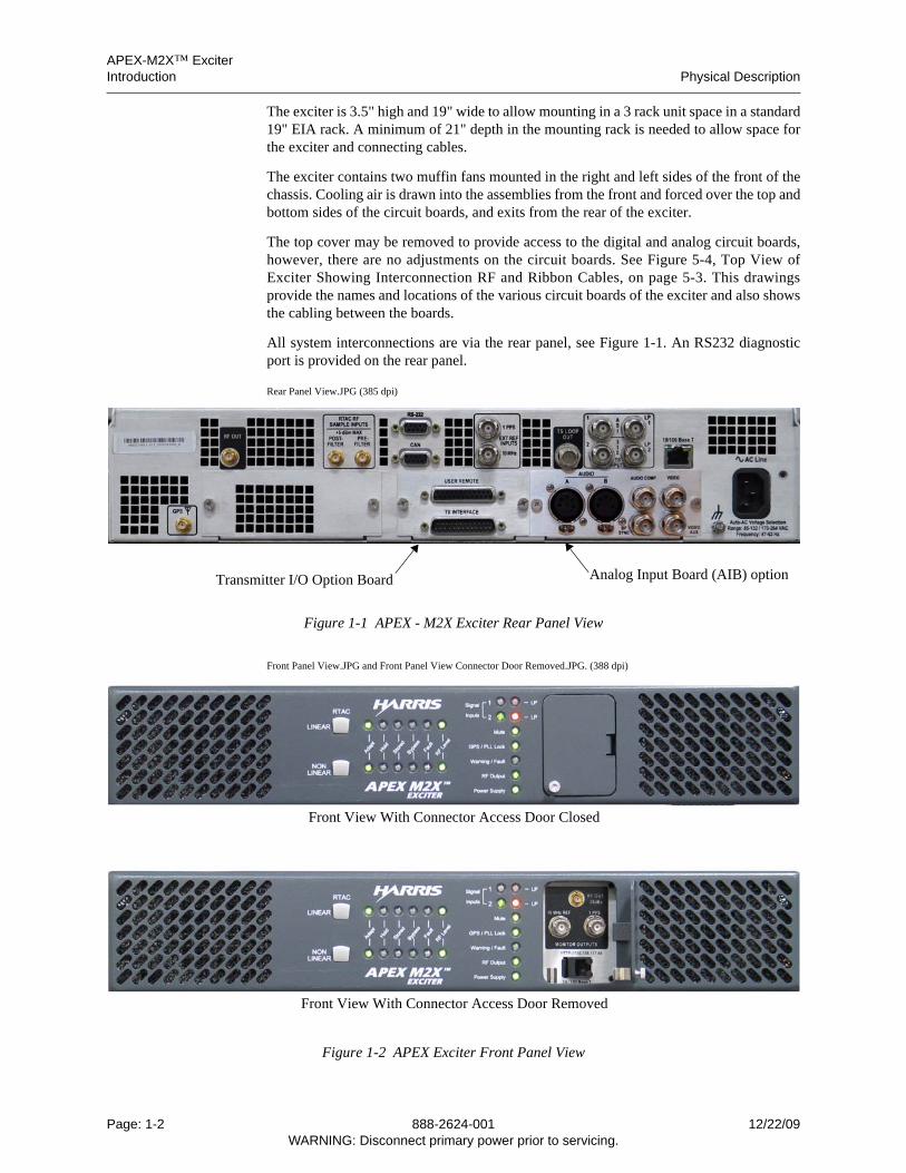
The exciter is 3.5" high and 19" wide to allow mounting in a 3 rack unit space in a standard19" EIA rack. A minimum of 21" depth in the mounting rack is needed to allow space forthe exciter and connecting cables.
The exciter contains two muffin fans mounted in the right and left sides of the front of thechassis. Cooling air is drawn into the assemblies from the front and forced over the top andbottom sides of the circuit boards, and exits from the rear of the exciter.
The top cover may be removed to provide access to the digital and analog circuit boards,however, there are no adjustments on the circuit boards. See Figure 5-4, Top View ofExciter Showing Interconnection RF and Ribbon Cables, on page 5-3. This drawingsprovide the names and locations of the various circuit boards of the exciter and also showsthe cabling between the boards.
All system interconnections are via the rear panel, see Figure 1-1. An RS232 diagnosticport is provided on the rear panel.
Rear Panel View.JPG (385 dpi)
Figure 1-1 APEX - M2X Exciter Rear Panel View
Front Panel View.JPG and Front Panel View Connector Door Removed.JPG. (388 dpi)
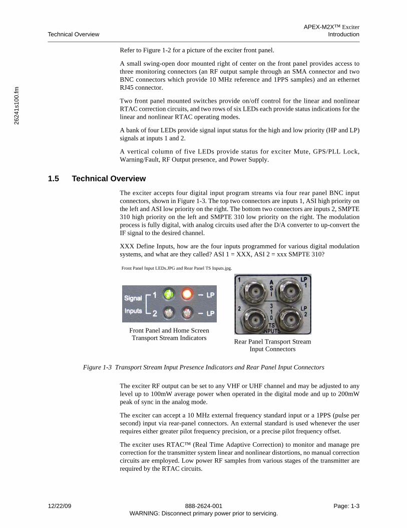
Figure 1-2 APEX Exciter Front Panel View
Transmitter I/O Option Board Analog Input Board (AIB) option
Front View With Connector Access Door Removed
Front View With Connector Access Door Closed
Page: 1-2 888-2624-001 12/22/09WARNING: Disconnect primary power prior to servicing.
APEX-M2X™ ExciterTechnical Overview Introduction
2624
1s1
00.fm
Refer to Figure 1-2 for a picture of the exciter front panel.
A small swing-open door mounted right of center on the front panel provides access tothree monitoring connectors (an RF output sample through an SMA connector and twoBNC connectors which provide 10 MHz reference and 1PPS samples) and an ethernetRJ45 connector.
Two front panel mounted switches provide on/off control for the linear and nonlinearRTAC correction circuits, and two rows of six LEDs each provide status indications for thelinear and nonlinear RTAC operating modes.
A bank of four LEDs provide signal input status for the high and low priority (HP and LP)signals at inputs 1 and 2.
A vertical column of five LEDs provide status for exciter Mute, GPS/PLL Lock,Warning/Fault, RF Output presence, and Power Supply.
1.5 Technical Overview
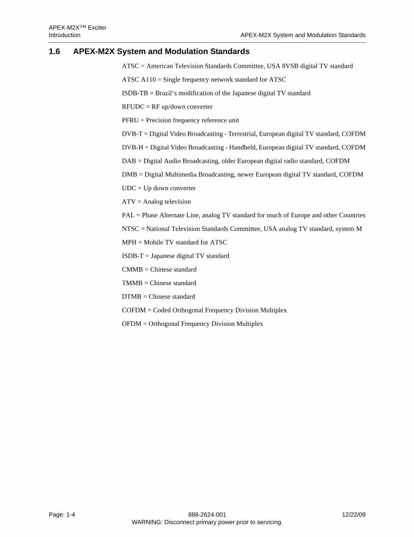
The exciter accepts four digital input program streams via four rear panel BNC inputconnectors, shown in Figure 1-3. The top two connectors are inputs 1, ASI high priority onthe left and ASI low priority on the right. The bottom two connectors are inputs 2, SMPTE310 high priority on the left and SMPTE 310 low priority on the right. The modulationprocess is fully digital, with analog circuits used after the D/A converter to up-convert theIF signal to the desired channel.
XXX Define Inputs, how are the four inputs programmed for various digital modulationsystems, and what are they called? ASI 1 = XXX, ASI 2 = xxx SMPTE 310?
Front Panel Input LEDs.JPG and Rear Panel TS Inputs.jpg.
Figure 1-3 Transport Stream Input Presence Indicators and Rear Panel Input Connectors
The exciter RF output can be set to any VHF or UHF channel and may be adjusted to anylevel up to 100mW average power when operated in the digital mode and up to 200mWpeak of sync in the analog mode.
The exciter can accept a 10 MHz external frequency standard input or a 1PPS (pulse persecond) input via rear-panel connectors. An external standard is used whenever the userrequires either greater pilot frequency precision, or a precise pilot frequency offset.
The exciter uses RTAC™ (Real Time Adaptive Correction) to monitor and manage precorrection for the transmitter system linear and nonlinear distortions, no manual correctioncircuits are employed. Low power RF samples from various stages of the transmitter arerequired by the RTAC circuits.
Front Panel and Home ScreenTransport Stream Indicators
Rear Panel Transport StreamInput Connectors
12/22/09 888-2624-001 Page: 1-3WARNING: Disconnect primary power prior to servicing.
APEX-M2X™ ExciterIntroduction APEX-M2X System and Modulation Standards
1.6 APEX-M2X System and Modulation Standards
ATSC = American Television Standards Committee, USA 8VSB digital TV standard
ATSC A110 = Single frequency network standard for ATSC
ISDB-TB = Brazil’s modification of the Japanese digital TV standard
RFUDC = RF up/down converter
PFRU = Precision frequency reference unit
DVB-T = Digital Video Broadcasting - Terrestrial, European digital TV standard, COFDM
DVB-H = Digital Video Broadcasting - Handheld, European digital TV standard, COFDM
DAB = Digital Audio Broadcasting, older European digital radio standard, COFDM
DMB = Digital Multimedia Broadcasting, newer European digital TV standard, COFDM
UDC = Up down converter
ATV = Analog television
PAL = Phase Alternate Line, analog TV standard for much of Europe and other Countries
NTSC = National Television Standards Committee, USA analog TV standard, system M
MPH = Mobile TV standard for ATSC
ISDB-T = Japanese digital TV standard
CMMB = Chinese standard
TMMB = Chinese standard
DTMB = Chinese standard
COFDM = Coded Orthogonal Frequency Division Multiplex
OFDM = Orthogonal Frequency Division Multiplex
Page: 1-4 888-2624-001 12/22/09WARNING: Disconnect primary power prior to servicing.
APEX-M2X™ ExciterAPEX-M2X Exciter Specifications Introduction
2624
1s1
00.fm
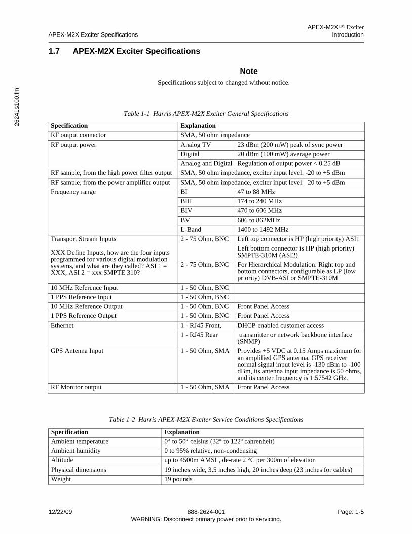
1.7 APEX-M2X Exciter Specifications
NoteSpecifications subject to changed without notice.
Table 1-1 Harris APEX-M2X Exciter General Specifications
Specification Explanation
RF output connector SMA, 50 ohm impedance
RF output power Analog TV 23 dBm (200 mW) peak of sync power
Digital 20 dBm (100 mW) average power
Analog and Digital Regulation of output power < 0.25 dB
RF sample, from the high power filter output SMA, 50 ohm impedance, exciter input level: -20 to +5 dBm
RF sample, from the power amplifier output SMA, 50 ohm impedance, exciter input level: -20 to +5 dBm
Frequency range BI 47 to 88 MHz
BIII 174 to 240 MHz
BIV 470 to 606 MHz
BV 606 to 862MHz
L-Band 1400 to 1492 MHz
Transport Stream Inputs
XXX Define Inputs, how are the four inputs programmed for various digital modulation systems, and what are they called? ASI 1 = XXX, ASI 2 = xxx SMPTE 310?
2 - 75 Ohm, BNC Left top connector is HP (high priority) ASI1
Left bottom connector is HP (high priority) SMPTE-310M (ASI2)
2 - 75 Ohm, BNC For Hierarchical Modulation. Right top and bottom connectors, configurable as LP (low priority) DVB-ASI or SMPTE-310M
10 MHz Reference Input 1 - 50 Ohm, BNC
1 PPS Reference Input 1 - 50 Ohm, BNC
10 MHz Reference Output 1 - 50 Ohm, BNC Front Panel Access
1 PPS Reference Output 1 - 50 Ohm, BNC Front Panel Access
Ethernet 1 - RJ45 Front, DHCP-enabled customer access
1 - RJ45 Rear transmitter or network backbone interface (SNMP)
GPS Antenna Input 1 - 50 Ohm, SMA Provides +5 VDC at 0.15 Amps maximum for an amplified GPS antenna. GPS receiver normal signal input level is -130 dBm to -100 dBm, its antenna input impedance is 50 ohms, and its center frequency is 1.57542 GHz.
RF Monitor output 1 - 50 Ohm, SMA Front Panel Access
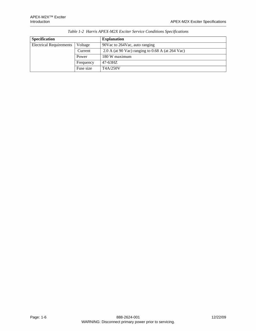
Table 1-2 Harris APEX-M2X Exciter Service Conditions Specifications
Specification Explanation
Ambient temperature 0 to 50 celsius (32 to 122 fahrenheit)
Ambient humidity 0 to 95% relative, non-condensing
Altitude up to 4500m AMSL, de-rate 2 °C per 300m of elevation
Physical dimensions 19 inches wide, 3.5 inches high, 20 inches deep (23 inches for cables)
Weight 19 pounds
12/22/09 888-2624-001 Page: 1-5WARNING: Disconnect primary power prior to servicing.
APEX-M2X™ ExciterIntroduction APEX-M2X Exciter Specifications
Electrical Requirements Voltage 90Vac to 264Vac, auto ranging
Current 2.0 A (at 90 Vac) ranging to 0.68 A (at 264 Vac)
Power 180 W maximum
Frequency 47-63HZ
Fuse size T4A/250V
Table 1-2 Harris APEX-M2X Exciter Service Conditions Specifications
Specification Explanation
Page: 1-6 888-2624-001 12/22/09WARNING: Disconnect primary power prior to servicing.
APEX-M2X™ ExciterAPEX-M2X Exciter Specifications Introduction
2624
1s1
00.fm
1.7.1 Transmitter I/O Board Option Connectors
1.7.1.1 Bottom Rear Panel, UHF Transmitter Interface Connector
Table 1-3 Transmitter I/O Bottom Rear Panel Control/Status Connector
Bottom Connector - 25 Pin Male (UHF Transmitter Interface Connector)Signal, Digital/Analog Direction Description, Digital/Analog Control I/O Assignment
1 Power RaiseVisual Raise
Input Digital: power raise commandAnalog: visual power raise command
I/O Bus 0
2 Power LowerVisual Lower
Input Digital: power lower commandAnalog: visual power lower command
I/O Bus 1
3 not usedAural Raise
Input Digital: not usedAnalog: aural power raise command
I/O Bus 2
4 not usedAural Lower
Input Digital: not usedAnalog: aural power lower command
I/O Bus 3
5 not usedAural Mute Command
Input Digital: not usedAnalog: aural mute command
I/O Bus 4
6 RF Mute CommandVisual Mute Command
Input Digital: RF mute commandAnalog: visual mute command
Input directly to Signal Processing board
7 not usedAural Mute Status
Output Digital: not usedAnalog: aural mute status
I/O Bus 5
8 RF Mute StatusVisual Mute Status
Output Digital: RF mute statusAnalog: visual mute status
I/O Bus 6
9 UPS Shutdown Input Disables battery backup functionality Input directly to Signal Processing board
10 EQ Reset Input Resets adaptive correction tables to default
I/O Bus 16
11 EQ Hold Input Holds current adaptive correction tables
I/O Bus 7
12 Power FoldbackVisual VSWR Input
Input Digital: analog input, 0 – 5V, used for power foldbackAnalog: analog input, 0 – 5V, used for visual power foldback
Analog Input 0
13 not usedAural VSWR Input
Input Digital: not usedAnalog: analog input, 0 – 5V, used for aural power foldback
Analog Input 1
14 RS232 Port Enable Output Indicates that the exciter is active I/O Bus 815 RF Present Output Indicates that exciter RF output is valid I/O Bus 916 not used
Dual Correction StatusOutput Digital: not used
Analog:I/O Bus 10
17 not usedComposite To Mono Switch
Input Digital: not usedAnalog: Switches between composite and mono
I/O Bus 11
18 not usedNotch Diplexer Remote
Input Digital: not usedAnalog:
I/O Bus 12
19 not usedAural Group Delay Remote
Input Digital: not usedAnalog:
I/O Bus 13
20 Spare InVisual Unlock Status
Output Digital: spare command inputAnalog: visual unlock status
I/O Bus 14
21 Spare OutAural Unlock Status
Output Digital: spare status outputAnalog: aural unlock status
I/O Bus 15
22 GND Ground23 GND Ground
12/22/09 888-2624-001 Page: 1-7WARNING: Disconnect primary power prior to servicing.
APEX-M2X™ ExciterIntroduction APEX-M2X Exciter Specifications
1.7.1.2 Top Rear Panel, User Remote Connector
24 GND Ground25 GND Ground
Table 1-4 Transmitter I/O Top Rear Panel Control/Status Connector
Top Connector - 25 Pin Female (For User Remote)Signal, Digital/Analog Direction Description, Digital/Analog Control I/O Assignment
1 not usedVisual Power Sense
Output Digital: not usedAnalog: 0 – 4.096Vdc analog output representing visual power level
Analog Output 0
2 not used
Aural Power Sense
Output Digital: not usedAnalog: 0 – 4.096Vdc analog output representing aural power level
Analog Output 1
3 Spare Analog In 1 Input Digital: not usedAnalog: not used
Analog Input 2
4 Spare Analog In 2 Input Digital: not usedAnalog: not used
Analog Input 3
5 +12Vdc Output +12Vdc, 200mA max6 GND Ground7 GND Ground8 GND Ground9 GND Ground10 GND Ground11 Alarm 0 Common Alarm 0 Relay Common12 Alarm 0 Normally Closed Alarm 0 Relay Normally Closed
(Faulted) Position13 Alarm 0 Normally Open Alarm 0 Relay Normally Open
(Non-Faulted) Position14 Alarm 1 Common Alarm 1 Relay Common15 Alarm 1 Normally Closed Alarm 1 Relay Normally Closed
(Faulted) Position16 Alarm 1 Normally Open Alarm 1 Relay Normally Open
(Non-Faulted) Position17 Alarm 2 Common Alarm 2 Relay Common18 Alarm 2 Normally Closed Alarm 2 Relay Normally Closed
(Faulted) Position19 Alarm 2 Normally Open Alarm 2 Relay Normally Open
(Non-Faulted) Position20 Alarm 3 Common Alarm 3 Relay Common21 Alarm 3 Normally Closed Alarm 3 Relay Normally Closed
(Faulted) Position22 Alarm 3 Normally Open Alarm 3 Relay Normally Open
(Non-Faulted) Position23 Alarm 4 Common Alarm 4 Relay Common24 Alarm 4 Normally Closed Alarm 4 Relay Normally Closed
(Faulted) Position25 Alarm 4 Normally Open Alarm 4 Relay Normally Open
(Non-Faulted) Position
Table 1-3 Transmitter I/O Bottom Rear Panel Control/Status Connector
Page: 1-8 888-2624-001 12/22/09WARNING: Disconnect primary power prior to servicing.
APEX-M2X™ ExciterAPEX-M2X Exciter Specifications Introduction
2624
1s1
00.fm
1.7.1.3 VHF to UHF Transmitter Interface Adaptor Cable
The APEX-M2X exciter Transmitter I/O Board Option contains two 25 pin D sub connec-tors. The top (female) is the user remote connector, and the bottom (male) is the transmitter interface connector.
Harris VHF transmitters have a 37 pin male D sub connector for their transmitter interface.
An interface cable is available which has a 37 pin female D sub connector to connect to the VHF transmitter exciter control cable. This cable terminates in a male 25 pin D sub connector for the exciter transmitter I/O board top (user remote) connector and a female 25 pin D sub connector for the bottom (transmitter interface) transmitter I/O connector.
Table 1-5 lists the pinout for this interface cable.
Table 1-5 VHF To UHF Interface Cable
APEX-M2X UHF Connector Analog VHF Digital VHF
25 Pin Male (TX INTERFACE)(Cable interface is 25 Pin Female) 37 Pin Female 37 Pin Female
1 Visual Raise 1 Visual Raise 1 Power Raise
2 Visual Lower 2 Visual Lower 2 Power Lower
3 Aural Raise 3 Aural Raise
4 Aural Lower 4 Aural Lower
5 Aural Mute Command 5 Aural Mute Command
6 Visual Mute Command 6 Visual Mute Command 6 RF Mute Command
7 Aural Mute Status 10 Aural Mute Status
8 Visual Mute Status 9 Visual Mute Status 9 RF Mute Status
9 UPS Shutdown
10 EQ Reset 18 EQ Reset 18 EQ Reset
11 EQ Hold 19 EQ Hold 19 EQ Hold
12 Visual VSWR Input 15 Visual VSWR Input 15 VSWR Foldback Input
13 Aural VSWR Input 16 Aural VSWR Input
14 RS232 Port Enable 17 RS232 Port Enable 17 RS232 Port Enable
15 RF Present
16 Dual Correction Status 13 Dual Correction Status
17 Composite To Mono Switch 20 Composite To Mono Switch
18 Notch Diplexer Remote 21 Notch Diplexer Remote
19 Aural Group Delay Remote 22 Aural Group Delay Remote
20 Visual Unlock Status 11 Visual Unlock Status 11 PLL Unlock Status
21 Aural Unlock Status 12 Aural Unlock Status
22 GND 23 GND 23 GND
23 GND 24 GND 24 GND
24 GND 25 GND 25 GND
25 GND 26 GND 26 GND
25 Pin Female (USER REMOTE)(Cable interface is 25 Pin Male)1 Visual Power Sense 7 Visual Power Sense 7 Power Sense
2 Aural Power Sense 8 Aural Power Sense
12/22/09 888-2624-001 Page: 1-9WARNING: Disconnect primary power prior to servicing.
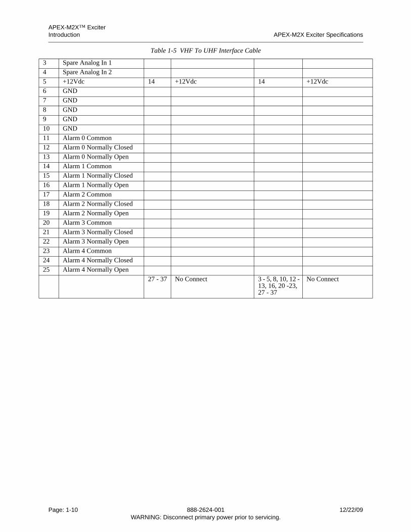
APEX-M2X™ ExciterIntroduction APEX-M2X Exciter Specifications
3 Spare Analog In 1
4 Spare Analog In 2
5 +12Vdc 14 +12Vdc 14 +12Vdc
6 GND
7 GND
8 GND
9 GND
10 GND
11 Alarm 0 Common
12 Alarm 0 Normally Closed
13 Alarm 0 Normally Open
14 Alarm 1 Common
15 Alarm 1 Normally Closed
16 Alarm 1 Normally Open
17 Alarm 2 Common
18 Alarm 2 Normally Closed
19 Alarm 2 Normally Open
20 Alarm 3 Common
21 Alarm 3 Normally Closed
22 Alarm 3 Normally Open
23 Alarm 4 Common
24 Alarm 4 Normally Closed
25 Alarm 4 Normally Open
27 - 37 No Connect 3 - 5, 8, 10, 12 - 13, 16, 20 -23, 27 - 37
No Connect
Table 1-5 VHF To UHF Interface Cable
Page: 1-10 888-2624-001 12/22/09WARNING: Disconnect primary power prior to servicing.
APEX-M2X™ ExciterAPEX-M2X Exciter Quick Start Guide Connecting To The APEX-M2X Exciter
2624
1s2
00.fm
2 Connecting To The APEX-M2X Exciter
Computer setup instructions given in this chapter are for the Windows XP operatingsystem.
2.1 APEX-M2X Exciter Quick Start Guide
If assistance is needed when first operating or installing a new APEX-M2X exciter, seeAppendix A, APEX-M2X Exciter Quick Start Guide.
2.2 Introduction
The APEX-M2X exciter does not have a GUI display, therefore, connection to it must bemade by a computer via an ethernet connection for setup, operation, and softwaredownloads.
This chapter contains the following sections:
• Section 2.3, Uses For The Exciter Front and Rear RJ45 Connectors, on page 2-1
• Section 2.4, Exciter Log In Authorization Levels, on page 2-2
• Section 2.6, Connection Through The Exciter Front Ethernet Connector, on page 2-3
• Section 2.7, Connecting Via The Exciter Rear Panel Ethernet Connector, on page 2-4
• Section 2.8, Exciter Ethernet Address For Transmitters Using eCDi., on page 2-5
• Section 2.9, Changing Computer Operating Mode Between Static and DHCP, on page 2-6
• Section 2.10, Exciter Screen Captures, on page 2-7
• Section 2.11, Software Downloads, on page 2-7
• Section 2.12, Ethernet Connection Via Tera Term, on page 2-11
• Section 2.13, Ethernet Connection Via HyperTerminal, on page 2-13
When the ethernet connection is made, the various screens will appear on the computer viaits Java program. If this program is not loaded onto the computer, it will be loaded onto thecomputer by the exciter once the ethernet connection has been established.
2.3 Uses For The Exciter Front and Rear RJ45 Connectors
The Front RJ45 Connector. As shipped from the factory, the exciter front RJ45 ethernetconnector has a fixed (static) IP address which is 192.168.117.88 The front RJ45 connectorof the exciter is intended for direct connection to a computer which is operated in theDHCP (dynamic host configuration protocol) client mode. The front connector is driven bya DHCP server which will automatically provide a proper IP address to a directlyconnected computer (operated in the DHCP client mode). This address will be192.168.117.yyy, where yyy ranges from 129 to 135.
When connecting to the exciter front panel ethernet port, if the computer being used doesnot auto-detect for cross connection, a crossover cable must be used to connect the exciterfront ethernet port to the computer.
12/22/09 888-2624-001 Page: 2-1WARNING: Disconnect primary power prior to servicing.
APEX-M2X™ ExciterConnecting To The APEX-M2X Exciter Exciter Log In Authorization Levels
The rear RJ45 connector of the exciter can operate in the DHCP client mode or static IP.It is intended for connection to an ethernet network which is driven by a DHCP server. Thatethernet network will supply the exciter rear connector with an appropriate IP addresswhen it is in the DHCP client mode.
Caution: Do not connect the exciter’s front RJ45 connector to a network because theDHCP server in the exciter will conflict with the DHCP server in the network.
DHCP Client Mode Computer. A computer operated in the DHCP client mode will begiven an appropriate IP address if connected to a network or device which is driven by aDHCP server.
Static Mode Computer. A computer operated in the static mode has a fixed IP address andwill not accept a new address offered by a DHCP server driven network.
2.4 Exciter Log In Authorization Levels
When the ethernet connection is established to the exciter, three levels of login are avail-able. They are:
• Two “Secure” level logins, which allow full access to the exciter programming func-tions.
• One monitor level login, which allows viewing only and no programming.
The default user name and password for the user 1 secure logins is admin, admin, and foruser 2 secure login the name is user2 and the password is pass2. If an improper user nameor password, each three or more characters with no spaces, is entered the monitor login isactivated.
2.5 Changing the User Name and Password
The secure login names and passwords are changed by an ethernet VT100 connection tothe exciter using Tera Term or Hyperterminal. The process of changing user names andpasswords (using Tera Term) is as follows.
1 Perform an ethernet VT100 login to the exciter using the front rear panel ethernet port. For connection details, see Section 2.12, Ethernet Connection Via Tera Term, on page 2-11 or Section 2.13, Ethernet Connection Via HyperTerminal, on page 2-13.
2 Navigate to page 4.
3 Enter U, for users.
4 The “Enter user number” prompt appears. Enter the user login to be changed (1 or 2).
A Press Enter to show the existing user name and password for users 1 and 2.
B Enter 1 to change user 1 login or enter 2 to change user 2 login.
5 If the existing user 1 and 2 logins are displayed, the prompt “Press ‘Y’ for a new en-try” appears.
A If y is pressed, the “Enter user number” prompt reappears.
B Enter 1 to change user 1 login or enter 2 to change user 2 login.
6 The “enter user name” prompt appears.
A Type the new name, then hit enter.
7 The “enter user password” prompt appears
A Type the new password, then hit enter.
Page: 2-2 888-2624-001 12/22/09WARNING: Disconnect primary power prior to servicing.
APEX-M2X™ ExciterConnection Through The Exciter Front Ethernet Connector Connecting To The APEX-M2X Exciter
2624
1s2
00.fm
8 The new user name and password are displayed.
9 The prompt “Press ‘Y’ for a new entry” appears.
A This allows the operator to change user 1 or 2 logins or to view both logins.
2.6 Connection Through The Exciter Front Ethernet Connector
When connecting to the exciter front panel RJ45 connector, the connecting computer canbe setup as a DHCP client, where the DHCP server associated with the exciter front RJ45port will assign an address to the computer. This method of obtaining a computer addressis described in Section 2.6.1, Obtaining Address With Computer in DHCP Client Mode.
The computer can be in the Static IP, where its address must be assigned manually. In thismode, its address must be assigned as 192.168.117.yyy, where yyy is any address between2 and 254, except 88.
When the computer has been assigned a correct address, connect to the exciter using theprocedure in Section 2.6.2, Making the Connection to the Exciter, on page 2-4.
NoteWhen connecting to the exciter front panel ethernet port, if thecomputer being used does not auto-detect for cross connection, acrossover cable must be used to connect the exciter front ethernetport to the computer.
2.6.1 Obtaining Address With Computer in DHCP Client Mode
If the computer is in the DHCP client mode, it will automatically obtain an address fromthe front panel RJ45 connector. Use the following procedure to obtain an address for thecomputer. Except for the need to reboot the computer, this is the easy way of obtainingan address.
1 Connect an ethernet cable between the computer’s RJ45 connector and the exciter front panel RJ45 connector.
2 Reboot the computer. The computer’s address should now be 192.168.117.yyy, where yyy ranges from 129 to 135.
3 It should be possible to connect to the exciter using the procedure in Section 2.6.2, Making the Connection to the Exciter, on page 2-4.
Depending on the setup of your computer, this procedure may fail because the computer isautomatically assigned a network address based on the network upon which it normallyoperates. If this procedure fails, use the procedure listed below.
2.6.1.1 Obtaining A Computer Address Without Rebooting
1 Connect an ethernet cable between the computer’s RJ45 connector and the exciter front panel RJ45 connector.
2 Press Start > Run.
3 The Run window should open.
4 The run window open box should display cmd. If not, type cmd, then press ok.
5 The cmd.exe window will open.
6 Type in ipconfig/release, then hit enter.
12/22/09 888-2624-001 Page: 2-3WARNING: Disconnect primary power prior to servicing.
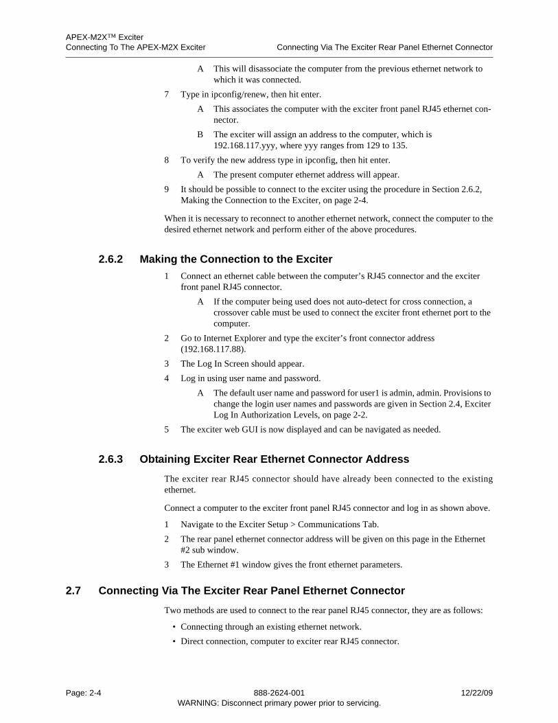
APEX-M2X™ ExciterConnecting To The APEX-M2X Exciter Connecting Via The Exciter Rear Panel Ethernet Connector
A This will disassociate the computer from the previous ethernet network to which it was connected.
7 Type in ipconfig/renew, then hit enter.
A This associates the computer with the exciter front panel RJ45 ethernet con-nector.
B The exciter will assign an address to the computer, which is 192.168.117.yyy, where yyy ranges from 129 to 135.
8 To verify the new address type in ipconfig, then hit enter.
A The present computer ethernet address will appear.
9 It should be possible to connect to the exciter using the procedure in Section 2.6.2, Making the Connection to the Exciter, on page 2-4.
When it is necessary to reconnect to another ethernet network, connect the computer to thedesired ethernet network and perform either of the above procedures.
2.6.2 Making the Connection to the Exciter
1 Connect an ethernet cable between the computer’s RJ45 connector and the exciter front panel RJ45 connector.
A If the computer being used does not auto-detect for cross connection, a crossover cable must be used to connect the exciter front ethernet port to the computer.
2 Go to Internet Explorer and type the exciter’s front connector address (192.168.117.88).
3 The Log In Screen should appear.
4 Log in using user name and password.
A The default user name and password for user1 is admin, admin. Provisions to change the login user names and passwords are given in Section 2.4, Exciter Log In Authorization Levels, on page 2-2.
5 The exciter web GUI is now displayed and can be navigated as needed.
2.6.3 Obtaining Exciter Rear Ethernet Connector Address
The exciter rear RJ45 connector should have already been connected to the existingethernet.
Connect a computer to the exciter front panel RJ45 connector and log in as shown above.
1 Navigate to the Exciter Setup > Communications Tab.
2 The rear panel ethernet connector address will be given on this page in the Ethernet #2 sub window.
3 The Ethernet #1 window gives the front ethernet parameters.
2.7 Connecting Via The Exciter Rear Panel Ethernet Connector
Two methods are used to connect to the rear panel RJ45 connector, they are as follows:
• Connecting through an existing ethernet network.
• Direct connection, computer to exciter rear RJ45 connector.
Page: 2-4 888-2624-001 12/22/09WARNING: Disconnect primary power prior to servicing.
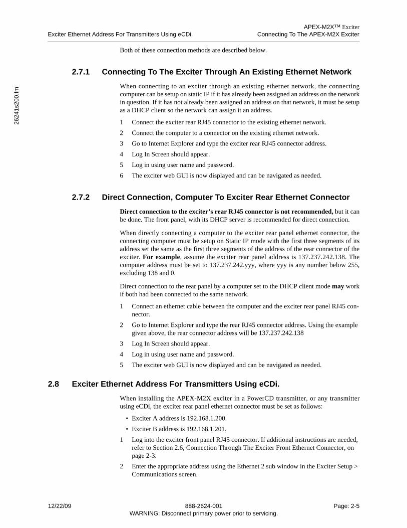
APEX-M2X™ ExciterExciter Ethernet Address For Transmitters Using eCDi. Connecting To The APEX-M2X Exciter
2624
1s2
00.fm
Both of these connection methods are described below.
2.7.1 Connecting To The Exciter Through An Existing Ethernet Network
When connecting to an exciter through an existing ethernet network, the connectingcomputer can be setup on static IP if it has already been assigned an address on the networkin question. If it has not already been assigned an address on that network, it must be setupas a DHCP client so the network can assign it an address.
1 Connect the exciter rear RJ45 connector to the existing ethernet network.
2 Connect the computer to a connector on the existing ethernet network.
3 Go to Internet Explorer and type the exciter rear RJ45 connector address.
4 Log In Screen should appear.
5 Log in using user name and password.
6 The exciter web GUI is now displayed and can be navigated as needed.
2.7.2 Direct Connection, Computer To Exciter Rear Ethernet Connector
Direct connection to the exciter’s rear RJ45 connector is not recommended, but it canbe done. The front panel, with its DHCP server is recommended for direct connection.
When directly connecting a computer to the exciter rear panel ethernet connector, theconnecting computer must be setup on Static IP mode with the first three segments of itsaddress set the same as the first three segments of the address of the rear connector of theexciter. For example, assume the exciter rear panel address is 137.237.242.138. Thecomputer address must be set to 137.237.242.yyy, where yyy is any number below 255,excluding 138 and 0.
Direct connection to the rear panel by a computer set to the DHCP client mode may workif both had been connected to the same network.
1 Connect an ethernet cable between the computer and the exciter rear panel RJ45 con-nector.
2 Go to Internet Explorer and type the rear RJ45 connector address. Using the example given above, the rear connector address will be 137.237.242.138
3 Log In Screen should appear.
4 Log in using user name and password.
5 The exciter web GUI is now displayed and can be navigated as needed.
2.8 Exciter Ethernet Address For Transmitters Using eCDi.
When installing the APEX-M2X exciter in a PowerCD transmitter, or any transmitterusing eCDi, the exciter rear panel ethernet connector must be set as follows:
• Exciter A address is 192.168.1.200.
• Exciter B address is 192.168.1.201.
1 Log into the exciter front panel RJ45 connector. If additional instructions are needed, refer to Section 2.6, Connection Through The Exciter Front Ethernet Connector, on page 2-3.
2 Enter the appropriate address using the Ethernet 2 sub window in the Exciter Setup > Communications screen.
12/22/09 888-2624-001 Page: 2-5WARNING: Disconnect primary power prior to servicing.
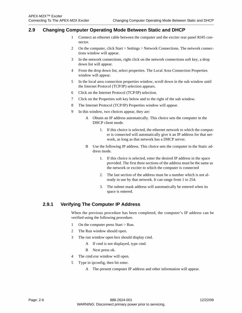
APEX-M2X™ ExciterConnecting To The APEX-M2X Exciter Changing Computer Operating Mode Between Static and DHCP
2.9 Changing Computer Operating Mode Between Static and DHCP
1 Connect an ethernet cable between the computer and the exciter rear panel RJ45 con-nector.
2 On the computer, click Start > Settings > Network Connections. The network connec-tions window will appear.
3 In the network connections, right click on the network connections soft key, a drop down list will appear.
4 From the drop down list, select properties. The Local Area Connection Properties window will appear.
5 In the local area connection properties window, scroll down in the sub window until the Internet Protocol (TCP/IP) selection appears.
6 Click on the Internet Protocol (TCP/IP) selection.
7 Click on the Properties soft key below and to the right of the sub window.
8 The Internet Protocol (TCP/IP) Properties window will appear.
9 In this window, two choices appear, they are:
A Obtain an IP address automatically. This choice sets the computer in the DHCP client mode.
1. If this choice is selected, the ethernet network to which the comput-er is connected will automatically give it an IP address for that net-work, as long as that network has a DHCP server.
B Use the following IP address. This choice sets the computer in the Static ad-dress mode.
1. If this choice is selected, enter the desired IP address in the space provided. The first three sections of the address must be the same as the network or exciter to which the computer is connected
2. The last section of the address must be a number which is not al-ready in use by that network. It can range from 1 to 254.
3. The subnet mask address will automatically be entered when its space is entered.
2.9.1 Verifying The Computer IP Address
When the previous procedure has been completed, the computer’s IP address can beverified using the following procedure.
1 On the computer press Start > Run.
2 The Run window should open.
3 The run window open box should display cmd.
A If cmd is not displayed, type cmd.
B Next press ok.
4 The cmd.exe window will open.
5 Type in ipconfig, then hit enter.
A The present computer IP address and other information will appear.
Page: 2-6 888-2624-001 12/22/09WARNING: Disconnect primary power prior to servicing.
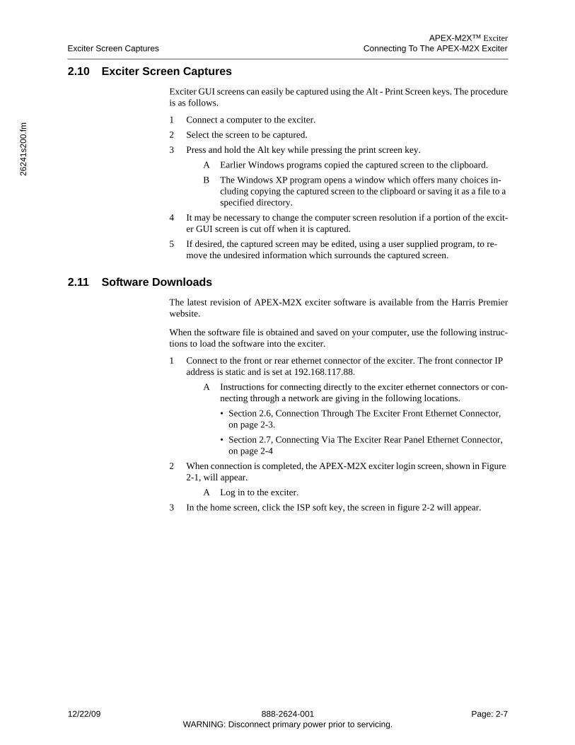
APEX-M2X™ ExciterExciter Screen Captures Connecting To The APEX-M2X Exciter
2624
1s2
00.fm
2.10 Exciter Screen Captures
Exciter GUI screens can easily be captured using the Alt - Print Screen keys. The procedureis as follows.
1 Connect a computer to the exciter.
2 Select the screen to be captured.
3 Press and hold the Alt key while pressing the print screen key.
A Earlier Windows programs copied the captured screen to the clipboard.
B The Windows XP program opens a window which offers many choices in-cluding copying the captured screen to the clipboard or saving it as a file to a specified directory.
4 It may be necessary to change the computer screen resolution if a portion of the excit-er GUI screen is cut off when it is captured.
5 If desired, the captured screen may be edited, using a user supplied program, to re-move the undesired information which surrounds the captured screen.
2.11 Software Downloads
The latest revision of APEX-M2X exciter software is available from the Harris Premierwebsite.
When the software file is obtained and saved on your computer, use the following instruc-tions to load the software into the exciter.
1 Connect to the front or rear ethernet connector of the exciter. The front connector IP address is static and is set at 192.168.117.88.
A Instructions for connecting directly to the exciter ethernet connectors or con-necting through a network are giving in the following locations.
• Section 2.6, Connection Through The Exciter Front Ethernet Connector, on page 2-3.
• Section 2.7, Connecting Via The Exciter Rear Panel Ethernet Connector, on page 2-4
2 When connection is completed, the APEX-M2X exciter login screen, shown in Figure 2-1, will appear.
A Log in to the exciter.
3 In the home screen, click the ISP soft key, the screen in figure 2-2 will appear.
12/22/09 888-2624-001 Page: 2-7WARNING: Disconnect primary power prior to servicing.
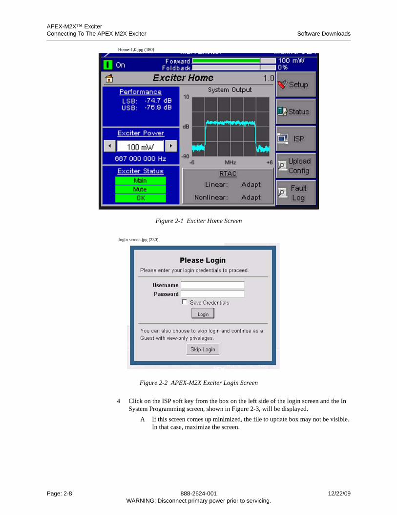
APEX-M2X™ ExciterConnecting To The APEX-M2X Exciter Software Downloads
Home-1,0.jpg (180)
Figure 2-1 Exciter Home Screen
login screen.jpg (230)
Figure 2-2 APEX-M2X Exciter Login Screen
4 Click on the ISP soft key from the box on the left side of the login screen and the In System Programming screen, shown in Figure 2-3, will be displayed.
A If this screen comes up minimized, the file to update box may not be visible. In that case, maximize the screen.
Page: 2-8 888-2624-001 12/22/09WARNING: Disconnect primary power prior to servicing.
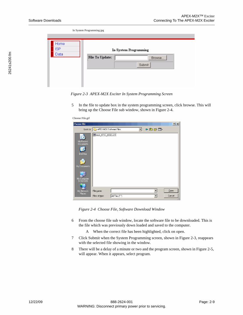
APEX-M2X™ ExciterSoftware Downloads Connecting To The APEX-M2X Exciter
2624
1s2
00.fm
In System Programming.jpg
Figure 2-3 APEX-M2X Exciter In System Programming Screen
5 In the file to update box in the system programming screen, click browse. This will bring up the Choose File sub window, shown in Figure 2-4.
Choose File.gif
Figure 2-4 Choose File, Software Download Window
6 From the choose file sub window, locate the software file to be downloaded. This is the file which was previously down loaded and saved to the computer.
A When the correct file has been highlighted, click on open.
7 Click Submit when the System Programming screen, shown in Figure 2-3, reappears with the selected file showing in the window.
8 There will be a delay of a minute or two and the program screen, shown in Figure 2-5, will appear. When it appears, select program.
12/22/09 888-2624-001 Page: 2-9WARNING: Disconnect primary power prior to servicing.
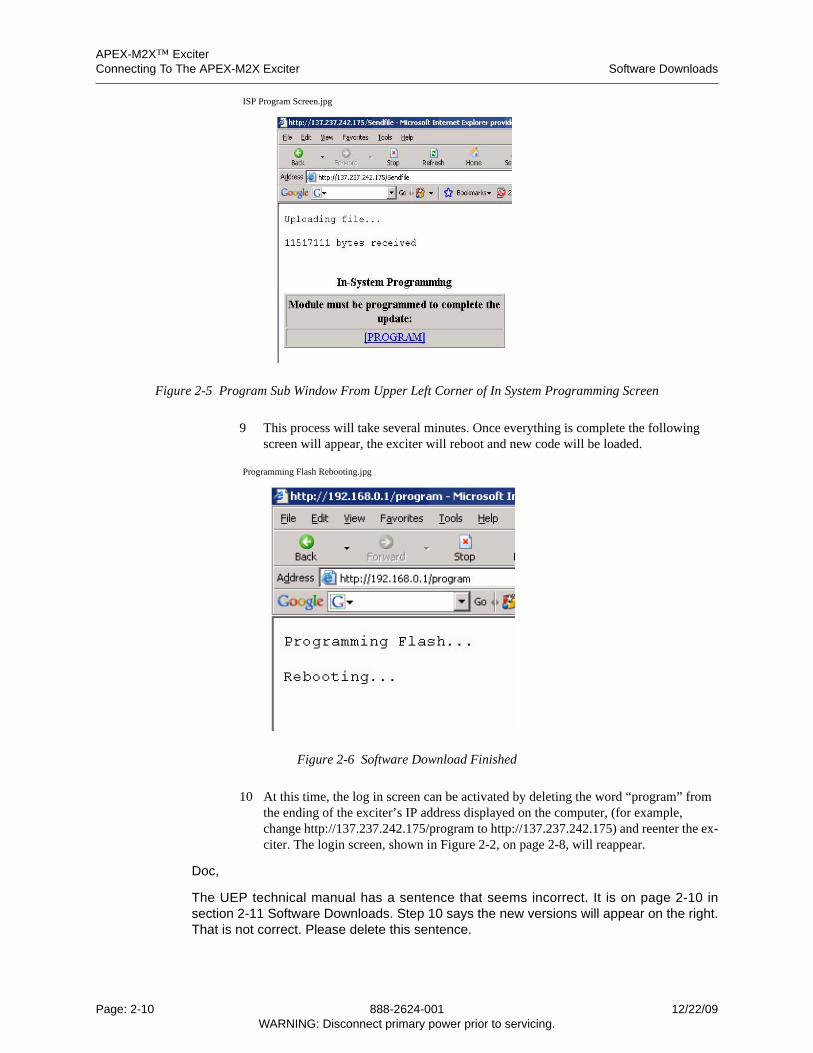
APEX-M2X™ ExciterConnecting To The APEX-M2X Exciter Software Downloads
ISP Program Screen.jpg
Figure 2-5 Program Sub Window From Upper Left Corner of In System Programming Screen
9 This process will take several minutes. Once everything is complete the following screen will appear, the exciter will reboot and new code will be loaded.
Programming Flash Rebooting.jpg
Figure 2-6 Software Download Finished
10 At this time, the log in screen can be activated by deleting the word “program” from the ending of the exciter’s IP address displayed on the computer, (for example, change http://137.237.242.175/program to http://137.237.242.175) and reenter the ex-citer. The login screen, shown in Figure 2-2, on page 2-8, will reappear.
Doc,
The UEP technical manual has a sentence that seems incorrect. It is on page 2-10 insection 2-11 Software Downloads. Step 10 says the new versions will appear on the right.That is not correct. Please delete this sentence.
Page: 2-10 888-2624-001 12/22/09WARNING: Disconnect primary power prior to servicing.
APEX-M2X™ ExciterEthernet Connection Via Tera Term Connecting To The APEX-M2X Exciter
2624
1s2
00.fm
10 You can then log into the exciter (name and password). The new revisions will appear
on the right side of the screen.
A In the exciter setup screen, the modulator which is loaded can now be seen.
B To change the modulation mode, go to exciter setup and use the up or down
arrows to select the desired modulation method.
Scott
11 You can then log into the exciter (name and password). The new revisions will appear on the right side of the screen.
A In the exciter setup screen, the modulator which is loaded can now be seen.
B To change the modulation mode, go to exciter setup and use the up or down arrows to select the desired modulation method.
2.12 Ethernet Connection Via Tera Term
This is a last resort connection, used for exciter troubleshooting, and can also be used tochange user login name and password, see Section 2.5, Changing the User Name andPassword, on page 2-2.
1 The computer must be capable of making an ethernet connection through the exciter’s front or rear RJ45 connectors.
A Connection through the exciter’s front connector is described in Section 2.6, Connection Through The Exciter Front Ethernet Connector, on page 2-3.
B Connection through the exciter’s rear connector is described in Section 2.7, Connecting Via The Exciter Rear Panel Ethernet Connector, on page 2-4
2 Open Tera Term on the computer.
3 Select File > New Connection. The Tera Term: New Connection window will open.
4 Select the TCP/IP choice. The Host sub window will become active.
5 Type the exciter’s IP address, for the RJ45 connector (front or rear) being used, in the host sub window.
6 Press the OK soft key.
7 When the connection is made, a window will appear with the words “Enter pass-word”. Type the User1 or User2 password and hit enter.
8 If the password is accepted, one of several screens will appear, see Figure 2-7 for a typical screen view.
A This display has several pages. Use the left or right arrow key to change the page being viewed.
12/22/09 888-2624-001 Page: 2-11WARNING: Disconnect primary power prior to servicing.
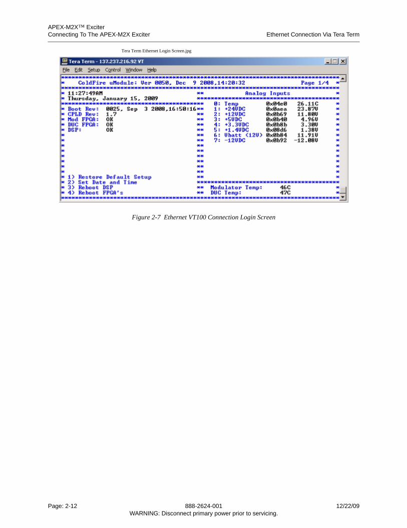
APEX-M2X™ ExciterConnecting To The APEX-M2X Exciter Ethernet Connection Via Tera Term
Tera Term Ethernet Login Screen.jpg
Figure 2-7 Ethernet VT100 Connection Login Screen
Page: 2-12 888-2624-001 12/22/09WARNING: Disconnect primary power prior to servicing.
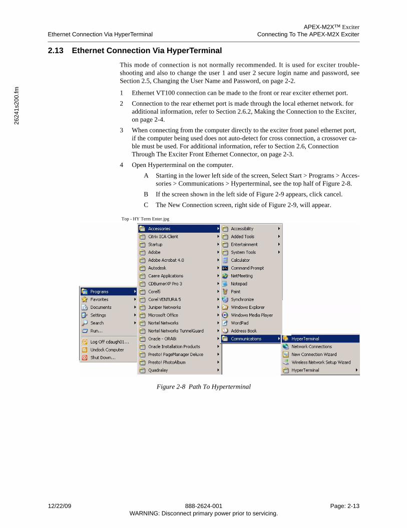
APEX-M2X™ ExciterEthernet Connection Via HyperTerminal Connecting To The APEX-M2X Exciter
2624
1s2
00.fm
2.13 Ethernet Connection Via HyperTerminal
This mode of connection is not normally recommended. It is used for exciter trouble-shooting and also to change the user 1 and user 2 secure login name and password, seeSection 2.5, Changing the User Name and Password, on page 2-2.
1 Ethernet VT100 connection can be made to the front or rear exciter ethernet port.
2 Connection to the rear ethernet port is made through the local ethernet network. for additional information, refer to Section 2.6.2, Making the Connection to the Exciter, on page 2-4.
3 When connecting from the computer directly to the exciter front panel ethernet port, if the computer being used does not auto-detect for cross connection, a crossover ca-ble must be used. For additional information, refer to Section 2.6, Connection Through The Exciter Front Ethernet Connector, on page 2-3.
4 Open Hyperterminal on the computer.
A Starting in the lower left side of the screen, Select Start > Programs > Acces-sories > Communications > Hyperterminal, see the top half of Figure 2-8.
B If the screen shown in the left side of Figure 2-9 appears, click cancel.
C The New Connection screen, right side of Figure 2-9, will appear.
Top - HY Term Enter.jpg
Figure 2-8 Path To Hyperterminal
12/22/09 888-2624-001 Page: 2-13WARNING: Disconnect primary power prior to servicing.
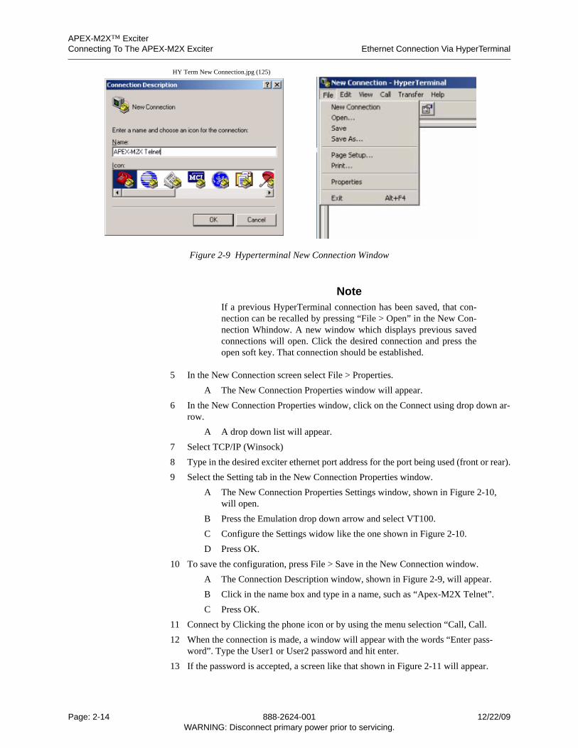
APEX-M2X™ ExciterConnecting To The APEX-M2X Exciter Ethernet Connection Via HyperTerminal
HY Term New Connection.jpg (125)
Figure 2-9 Hyperterminal New Connection Window
NoteIf a previous HyperTerminal connection has been saved, that con-nection can be recalled by pressing “File > Open” in the New Con-nection Whindow. A new window which displays previous savedconnections will open. Click the desired connection and press theopen soft key. That connection should be established.
5 In the New Connection screen select File > Properties.
A The New Connection Properties window will appear.
6 In the New Connection Properties window, click on the Connect using drop down ar-row.
A A drop down list will appear.
7 Select TCP/IP (Winsock)
8 Type in the desired exciter ethernet port address for the port being used (front or rear).
9 Select the Setting tab in the New Connection Properties window.
A The New Connection Properties Settings window, shown in Figure 2-10, will open.
B Press the Emulation drop down arrow and select VT100.
C Configure the Settings widow like the one shown in Figure 2-10.
D Press OK.
10 To save the configuration, press File > Save in the New Connection window.
A The Connection Description window, shown in Figure 2-9, will appear.
B Click in the name box and type in a name, such as “Apex-M2X Telnet”.
C Press OK.
11 Connect by Clicking the phone icon or by using the menu selection “Call, Call.
12 When the connection is made, a window will appear with the words “Enter pass-word”. Type the User1 or User2 password and hit enter.
13 If the password is accepted, a screen like that shown in Figure 2-11 will appear.
Page: 2-14 888-2624-001 12/22/09WARNING: Disconnect primary power prior to servicing.
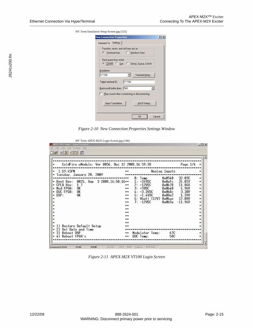
APEX-M2X™ ExciterEthernet Connection Via HyperTerminal Connecting To The APEX-M2X Exciter
2624
1s2
00.fm
HY Term Emulation Setup Screen.jpg (125)
Figure 2-10 New Connection Properties Settings Window
HY Term APEX-M2X Login Screen.jpg (140)
Figure 2-11 APEX-M2X VT100 Login Screen
12/22/09 888-2624-001 Page: 2-15WARNING: Disconnect primary power prior to servicing.

APEX-M2X™ ExciterConnecting To The APEX-M2X Exciter Ethernet Connection Via HyperTerminal
Page: 2-16 888-2624-001 12/22/09WARNING: Disconnect primary power prior to servicing.
APEX-M2X™ Exciter, Incorporating FLO™ TechnologyGUI Screen Selections Within This Chapter Operating the APEX-M2X Exciter, FLO Mode
2624
6s3
00
New
Scr
een
s.fm
3 Operating the APEX-M2X Exciter, FLO Mode
The APEX-M2X does not have an off/on switch. Power is applied to the unit by pluggingan energized power cord into the ac connector on the back of the exciter. The exciter willoperate over a voltage range of 90 to 264Vac, auto ranging.
3.1 GUI Screen Selections Within This Chapter
• Section 3.3, Home Screen, on page 3-3.
• Section 3.4, Flow Chart For Home Screen, on page 3-9
• Section 3.5, RTAC Setup Screen, on page 3-10
• Section 3.6, Setup Navigation Screen, on page 3-11.
• Section 3.6.1, Setup Navigation FLow Chart, on page 3-12
• Section 3.7, System Setup Screen, on page 3-13.
• Section 3.8, RTAC Setup Screen 1, Special Modes And RTAC Profiles, on page 3-15.
• Section 3.9, RTAC Setup Screen 2, Stored Correction Sets, on page 3-17.
• Section 3.10, RTAC Setup Screen 3, on page 3-19.
• Section 3.11, FLO Setup Screen 1, on page 3-22.
• Section 3.12, FLO Setup Screen 2, on page 3-23.
• Section 3.13, FLO Setup Screen 3, on page 3-24.
• Section 3.14, FLO Setup Screen 4, on page 3-27.
• Section 3.15, FLO Setup Screen 5, on page 3-28.
• Section 3.16, FLO Setup Screen 6, on page 3-29.
• Section 3.17, FLO Setup Commands, on page 3-30.
• Section 3.18, Output Setup Screen, on page 3-31.
• Section 3.19, PFRU Setup Screen, on page 3-32.
• Section 3.20, Transmitter I/O Screen, on page 3-34.
• Section 3.21, Remote Communications Setup Screen 1, Ethernet, on page 3-36.
• Section 3.22, Remote Communications Setup Screen 2, RS232 and CAN, on page 3-37.
• Section 3.23, Remote Communications Setup Screen 3, SNMP, on page 3-38
• Section 3.24, Test (Pattern) Setup Screen, on page 3-39.
• Section 3.25, Status Navigation Screen, on page 3-40.
• Section 3.25.1, Status Negation Flow Chart, on page 3-41
• Section 3.26, Signal Processor Status Screen 1, on page 3-42.
• Section 3.27, Signal Processor Status Screen 2, on page 3-43.
12/22/09 888-2624-006 Page: 3-1WARNING: Disconnect primary power prior to servicing.
APEX-M2X™ Exciter, Incorporating FLO™ TechnologyOperating the APEX-M2X Exciter, FLO Mode GUI Screen Selections Within This Chapter
• Section 3.28, FLO (Modulator) Status Screen 1, on page 3-44.
• Section 3.29, FLO (Modulator) Status Screen 2, on page 3-46.
• Section 3.30, FLO (Modulator) Status Screen 3, on page 3-48.
• Section 3.31, RTAC Status Screen, Down Converter, on page 3-50.
• Section 3.32, Output Status Screen, Up Converter, on page 3-51.
• Section 3.33, Transmitter I/O Status Screen, on page 3-53.
• Section 3.34, PFRU Status Screen 1, on page 3-54.
• Section 3.35, PFRU Status Screen 2, on page 3-56.
• Section 3.36, Battery Backup Status Screen, on page 3-58.
• Section 3.37, Revisions Screen 1, on page 3-59
• Section 3.38, Revisions Screen 2, on page 3-60
• Section 3.39, Fault Log Screen, on page 3-61.
• Section 3.40, In Service Programming, ISP, on page 3-62.
Page: 3-2 888-2624-006 12/22/09WARNING: Disconnect primary power prior to servicing.
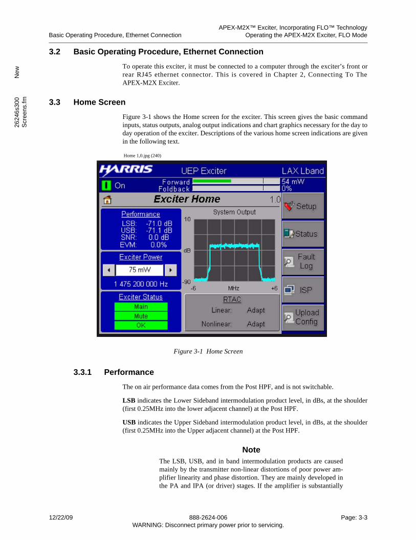
APEX-M2X™ Exciter, Incorporating FLO™ TechnologyBasic Operating Procedure, Ethernet Connection Operating the APEX-M2X Exciter, FLO Mode
2624
6s3
00
New
Scr
een
s.fm
3.2 Basic Operating Procedure, Ethernet Connection
To operate this exciter, it must be connected to a computer through the exciter’s front orrear RJ45 ethernet connector. This is covered in Chapter 2, Connecting To TheAPEX-M2X Exciter.
3.3 Home Screen
Figure 3-1 shows the Home screen for the exciter. This screen gives the basic commandinputs, status outputs, analog output indications and chart graphics necessary for the day today operation of the exciter. Descriptions of the various home screen indications are givenin the following text.
Home 1,0.jpg (240)
Figure 3-1 Home Screen
3.3.1 Performance
The on air performance data comes from the Post HPF, and is not switchable.
LSB indicates the Lower Sideband intermodulation product level, in dBs, at the shoulder(first 0.25MHz into the lower adjacent channel) at the Post HPF.
USB indicates the Upper Sideband intermodulation product level, in dBs, at the shoulder(first 0.25MHz into the Upper adjacent channel) at the Post HPF.
NoteThe LSB, USB, and in band intermodulation products are causedmainly by the transmitter non-linear distortions of poor power am-plifier linearity and phase distortion. They are mainly developed inthe PA and IPA (or driver) stages. If the amplifier is substantially
12/22/09 888-2624-006 Page: 3-3WARNING: Disconnect primary power prior to servicing.
APEX-M2X™ Exciter, Incorporating FLO™ TechnologyOperating the APEX-M2X Exciter, FLO Mode Home Screen
linear, the shoulders will be -36 dB or lower. As the non-linear dis-tortions increase, the shoulder levels will rise above -36 dB. Un-equal USB and LSB shoulder levels indicate the presence of phasedistortion.
SNR indicates the digital signal to noise ratio for the RF output signal at the output of themask filter (also called the high power filter).
EVM (error vector magnitude), in percent, is the value for the RF output signal at theoutput of the mask filter (also called the high power filter).
3.3.2 Raising or Lowering Output Power
The average output power of the exciter in mW is displayed numerically and on a bar graphon the home screen. Exciter output power adjustment provision is included on the homescreen.
On the home screen, exciter output power can be changed by pressing the left or rightarrows in the exciter power sub window, or it can be changed by writing the value in thewhite box.
1 Exciter output power is set by clicking in the white box above the forward power dis-play on the home screen.
A The computer keyboard can be used to enter the new power level (in mW).
In most transmitters, exciter output power is controlled from the transmitter, with trans-mitter output power controlled locally or remotely by a circuit within the transmitter. Insome transmitters the exciter output power control is the transmitter output power control,and is available by remote control.
3.3.3 Exciter Status Sub Window
This sub window concerns the status of the three exciter indicators (Main, Mute, andFault).
• If no warnings or faults exist within the exciter indication is green.
• When an exciter parameters approach its limit, the Warning - Fault indication turns yellow.
• If a fault occurs within the exciter, the Warning - Fault indication turns Red.
3.3.4 System Output Sub Window
The Chart, in the center of the Home screen shows the spectrum response of the transmitterafter the high power band pass filter (HPF) located at the output of the transmitter poweramplifier.
3.3.5 RTAC Status Sub Window
This sub window displays the current status of the linear and nonlinear RTAC (real timeadaptive correction) circuits. Possibilities are:
• Adapt: The correction algorithm is active and will continuously calculate and update correction as needed.
Page: 3-4 888-2624-006 12/22/09WARNING: Disconnect primary power prior to servicing.
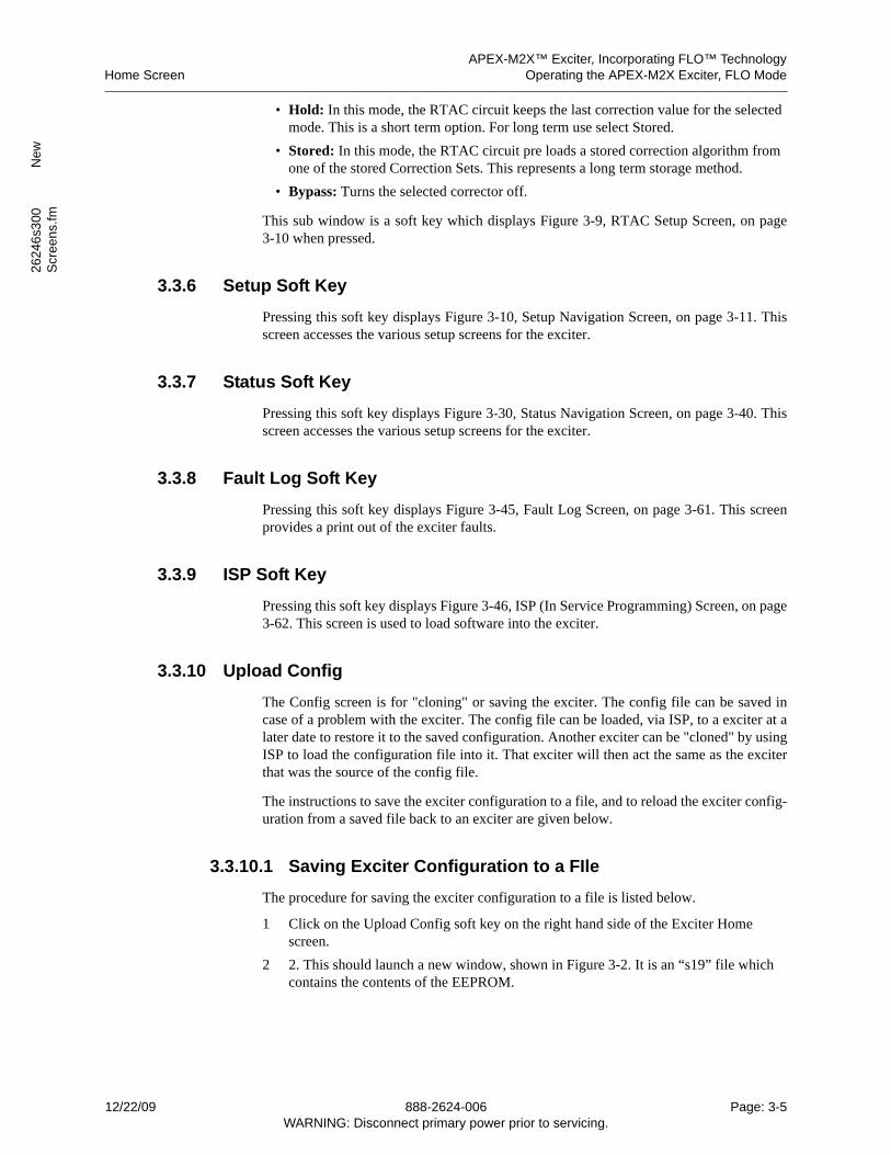
APEX-M2X™ Exciter, Incorporating FLO™ TechnologyHome Screen Operating the APEX-M2X Exciter, FLO Mode
2624
6s3
00
New
Scr
een
s.fm
• Hold: In this mode, the RTAC circuit keeps the last correction value for the selected mode. This is a short term option. For long term use select Stored.
• Stored: In this mode, the RTAC circuit pre loads a stored correction algorithm from one of the stored Correction Sets. This represents a long term storage method.
• Bypass: Turns the selected corrector off.
This sub window is a soft key which displays Figure 3-9, RTAC Setup Screen, on page3-10 when pressed.
3.3.6 Setup Soft Key
Pressing this soft key displays Figure 3-10, Setup Navigation Screen, on page 3-11. Thisscreen accesses the various setup screens for the exciter.
3.3.7 Status Soft Key
Pressing this soft key displays Figure 3-30, Status Navigation Screen, on page 3-40. Thisscreen accesses the various setup screens for the exciter.
3.3.8 Fault Log Soft Key
Pressing this soft key displays Figure 3-45, Fault Log Screen, on page 3-61. This screenprovides a print out of the exciter faults.
3.3.9 ISP Soft Key
Pressing this soft key displays Figure 3-46, ISP (In Service Programming) Screen, on page3-62. This screen is used to load software into the exciter.
3.3.10 Upload Config
The Config screen is for "cloning" or saving the exciter. The config file can be saved incase of a problem with the exciter. The config file can be loaded, via ISP, to a exciter at alater date to restore it to the saved configuration. Another exciter can be "cloned" by usingISP to load the configuration file into it. That exciter will then act the same as the exciterthat was the source of the config file.
The instructions to save the exciter configuration to a file, and to reload the exciter config-uration from a saved file back to an exciter are given below.
3.3.10.1 Saving Exciter Configuration to a FIle
The procedure for saving the exciter configuration to a file is listed below.
1 Click on the Upload Config soft key on the right hand side of the Exciter Home screen.
2 2. This should launch a new window, shown in Figure 3-2. It is an “s19” file which contains the contents of the EEPROM.
12/22/09 888-2624-006 Page: 3-5WARNING: Disconnect primary power prior to servicing.
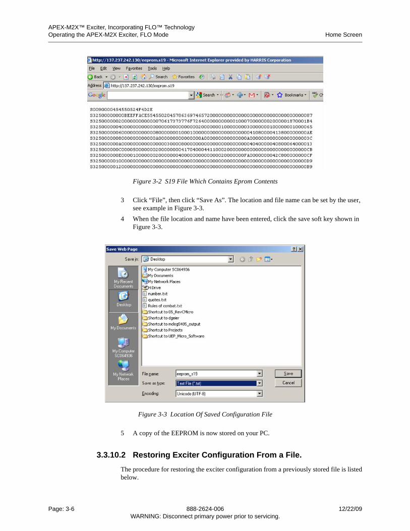
APEX-M2X™ Exciter, Incorporating FLO™ TechnologyOperating the APEX-M2X Exciter, FLO Mode Home Screen
Figure 3-2 S19 File Which Contains Eprom Contents
3 Click “File”, then click “Save As”. The location and file name can be set by the user, see example in Figure 3-3.
4 When the file location and name have been entered, click the save soft key shown in Figure 3-3.
Figure 3-3 Location Of Saved Configuration File
5 A copy of the EEPROM is now stored on your PC.
3.3.10.2 Restoring Exciter Configuration From a File.
The procedure for restoring the exciter configuration from a previously stored file is listedbelow.
Page: 3-6 888-2624-006 12/22/09WARNING: Disconnect primary power prior to servicing.
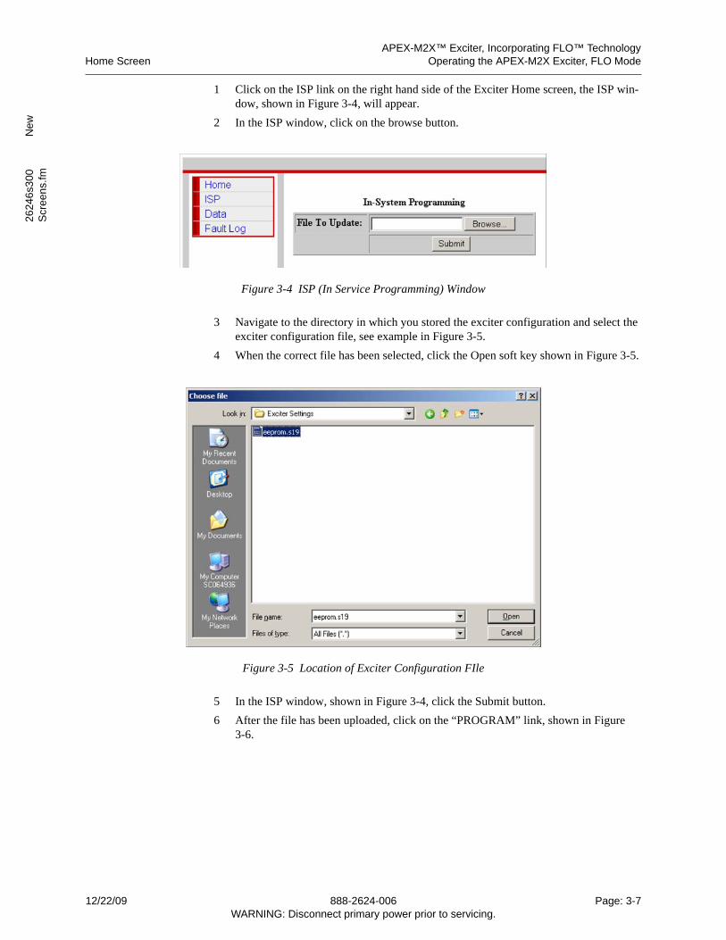
APEX-M2X™ Exciter, Incorporating FLO™ TechnologyHome Screen Operating the APEX-M2X Exciter, FLO Mode
2624
6s3
00
New
Scr
een
s.fm
1 Click on the ISP link on the right hand side of the Exciter Home screen, the ISP win-dow, shown in Figure 3-4, will appear.
2 In the ISP window, click on the browse button.
Figure 3-4 ISP (In Service Programming) Window
3 Navigate to the directory in which you stored the exciter configuration and select the exciter configuration file, see example in Figure 3-5.
4 When the correct file has been selected, click the Open soft key shown in Figure 3-5.
Figure 3-5 Location of Exciter Configuration FIle
5 In the ISP window, shown in Figure 3-4, click the Submit button.
6 After the file has been uploaded, click on the “PROGRAM” link, shown in Figure 3-6.
12/22/09 888-2624-006 Page: 3-7WARNING: Disconnect primary power prior to servicing.
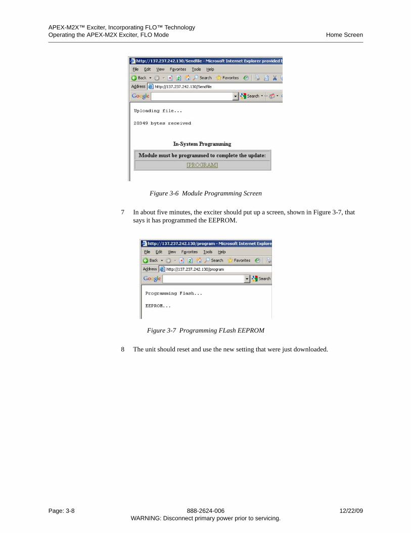
APEX-M2X™ Exciter, Incorporating FLO™ TechnologyOperating the APEX-M2X Exciter, FLO Mode Home Screen
Figure 3-6 Module Programming Screen
7 In about five minutes, the exciter should put up a screen, shown in Figure 3-7, that says it has programmed the EEPROM.
Figure 3-7 Programming FLash EEPROM
8 The unit should reset and use the new setting that were just downloaded.
Page: 3-8 888-2624-006 12/22/09WARNING: Disconnect primary power prior to servicing.
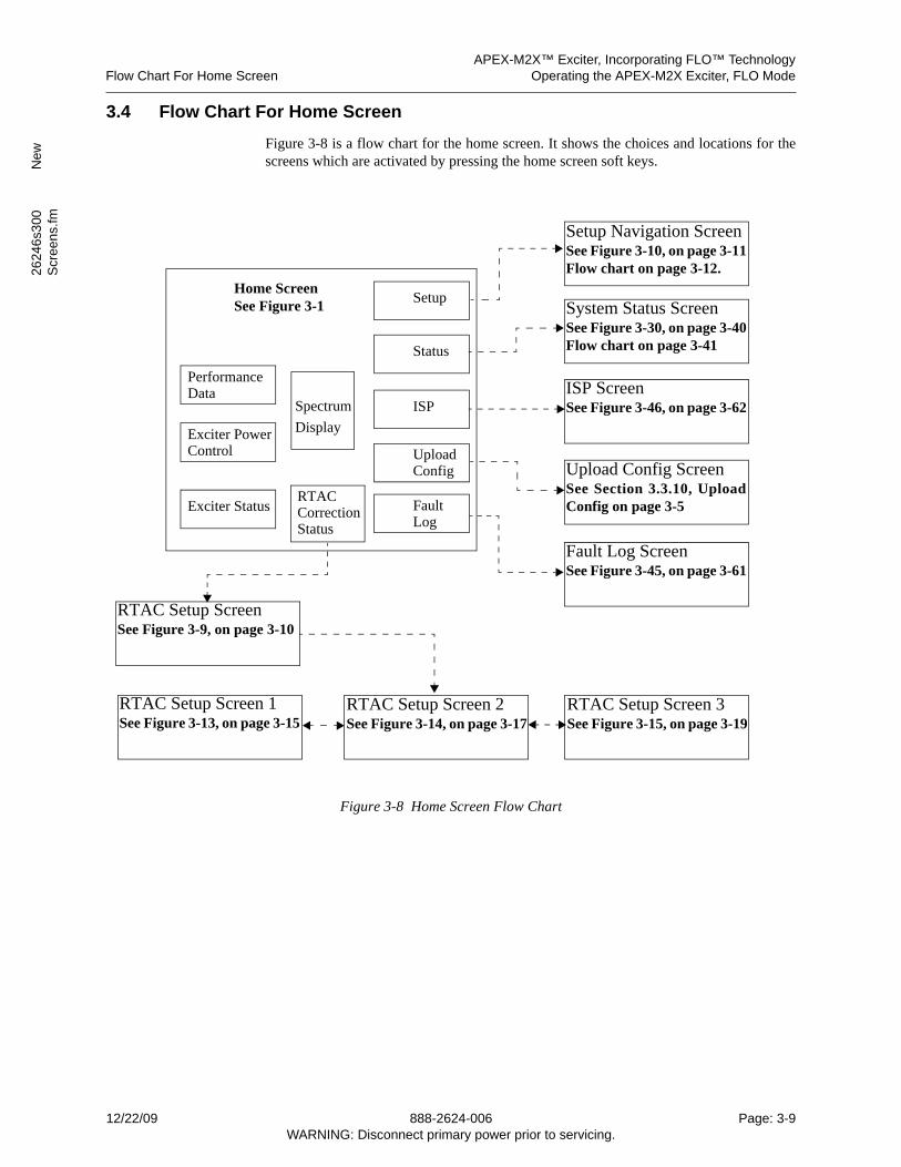
APEX-M2X™ Exciter, Incorporating FLO™ TechnologyFlow Chart For Home Screen Operating the APEX-M2X Exciter, FLO Mode
2624
6s3
00
New
Scr
een
s.fm
3.4 Flow Chart For Home Screen
Figure 3-8 is a flow chart for the home screen. It shows the choices and locations for thescreens which are activated by pressing the home screen soft keys.
Figure 3-8 Home Screen Flow Chart
Spectrum
RTACCorrectionStatus
Exciter PowerControl
Upload Config ScreenSee Section 3.3.10, UploadConfig on page 3-5
System Status ScreenSee Figure 3-30, on page 3-40Flow chart on page 3-41
Home Screen See Figure 3-1
Performance Data
Exciter Status
Display
Status
Setup
Upload
ISP
FaultLog
Setup Navigation ScreenSee Figure 3-10, on page 3-11Flow chart on page 3-12.
ISP ScreenSee Figure 3-46, on page 3-62
Fault Log ScreenSee Figure 3-45, on page 3-61
Config
RTAC Setup Screen 1See Figure 3-13, on page 3-15
RTAC Setup Screen 2See Figure 3-14, on page 3-17
RTAC Setup Screen 3See Figure 3-15, on page 3-19
RTAC Setup ScreenSee Figure 3-9, on page 3-10
12/22/09 888-2624-006 Page: 3-9WARNING: Disconnect primary power prior to servicing.
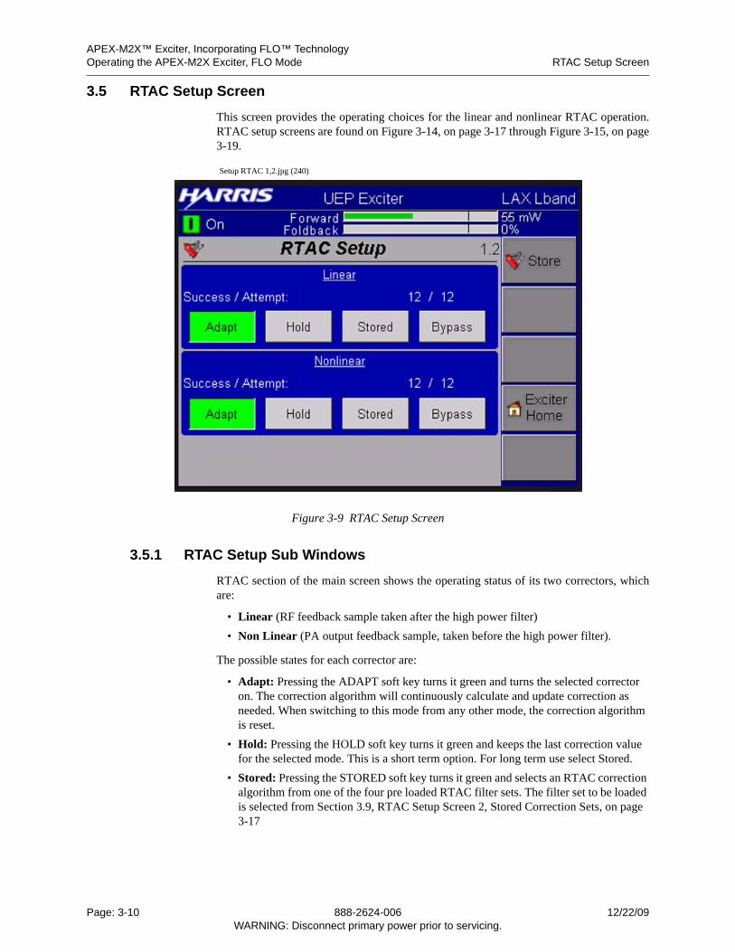
APEX-M2X™ Exciter, Incorporating FLO™ TechnologyOperating the APEX-M2X Exciter, FLO Mode RTAC Setup Screen
3.5 RTAC Setup Screen
This screen provides the operating choices for the linear and nonlinear RTAC operation.RTAC setup screens are found on Figure 3-14, on page 3-17 through Figure 3-15, on page3-19.
Setup RTAC 1,2.jpg (240)
Figure 3-9 RTAC Setup Screen
3.5.1 RTAC Setup Sub Windows
RTAC section of the main screen shows the operating status of its two correctors, whichare:
• Linear (RF feedback sample taken after the high power filter)
• Non Linear (PA output feedback sample, taken before the high power filter).
The possible states for each corrector are:
• Adapt: Pressing the ADAPT soft key turns it green and turns the selected corrector on. The correction algorithm will continuously calculate and update correction as needed. When switching to this mode from any other mode, the correction algorithm is reset.
• Hold: Pressing the HOLD soft key turns it green and keeps the last correction value for the selected mode. This is a short term option. For long term use select Stored.
• Stored: Pressing the STORED soft key turns it green and selects an RTAC correction algorithm from one of the four pre loaded RTAC filter sets. The filter set to be loaded is selected from Section 3.9, RTAC Setup Screen 2, Stored Correction Sets, on page 3-17
Page: 3-10 888-2624-006 12/22/09WARNING: Disconnect primary power prior to servicing.
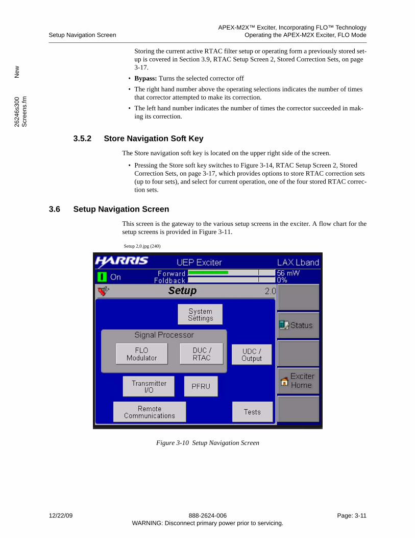
APEX-M2X™ Exciter, Incorporating FLO™ TechnologySetup Navigation Screen Operating the APEX-M2X Exciter, FLO Mode
2624
6s3
00
New
Scr
een
s.fm
Storing the current active RTAC filter setup or operating form a previously stored set-up is covered in Section 3.9, RTAC Setup Screen 2, Stored Correction Sets, on page 3-17.
• Bypass: Turns the selected corrector off
• The right hand number above the operating selections indicates the number of times that corrector attempted to make its correction.
• The left hand number indicates the number of times the corrector succeeded in mak-ing its correction.
3.5.2 Store Navigation Soft Key
The Store navigation soft key is located on the upper right side of the screen.
• Pressing the Store soft key switches to Figure 3-14, RTAC Setup Screen 2, Stored Correction Sets, on page 3-17, which provides options to store RTAC correction sets (up to four sets), and select for current operation, one of the four stored RTAC correc-tion sets.
3.6 Setup Navigation Screen
This screen is the gateway to the various setup screens in the exciter. A flow chart for thesetup screens is provided in Figure 3-11.
Setup 2,0.jpg (240)
Figure 3-10 Setup Navigation Screen
12/22/09 888-2624-006 Page: 3-11WARNING: Disconnect primary power prior to servicing.
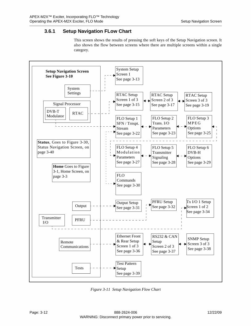
APEX-M2X™ Exciter, Incorporating FLO™ TechnologyOperating the APEX-M2X Exciter, FLO Mode Setup Navigation Screen
3.6.1 Setup Navigation FLow Chart
This screen shows the results of pressing the soft keys of the Setup Navigation screen. Italso shows the flow between screens where there are multiple screens within a singlecategory.
Figure 3-11 Setup Navigation Flow Chart
RTAC
Output
Transmitter
Setup Navigation Screen See Figure 3-10
System SetupScreen 1See page 3-13
PFRU SetupSee page 3-32
FLO Setup 1SFN / Trnspt.StreamSee page 3-22
FLO Setup 2Trans. I/OParametersSee page 3-23
FLO Setup 3M P E GOptionsSee page 3-25
SystemSettings
Status, Goes to Figure 3-30,Status Navigation Screen, onpage 3-40
Home Goes to Figure3-1, Home Screen, onpage 3-3
Output Setup See page 3-31
DVB-T Modulator
PFRU
Signal Processor
Remote Communications
I/O
Tests
FLO Setup 4Modula t ionParametersSee page 3-27
FLO Setup 5TransmitterSignalingSee page 3-28
FLO Setup 6DVB-HOptionsSee page 3-29
RTAC Setup Screen 1 of 3See page 3-15
RTAC Setup Screen 2 of 3See page 3-17
RTAC Setup Screen 3 of 3See page 3-19
Tx I/O 1 Setup Screen 1 of 2See page 3-34
Ethernet Front& Rear Setup Screen 1 of 3See page 3-36
RS232 & CANSetup Screen 2 of 3See page 3-37
Test PatternSetupSee page 3-39
SNMP SetupScreen 3 of 3See page 3-38
FLOCommandsSee page 3-30
Page: 3-12 888-2624-006 12/22/09WARNING: Disconnect primary power prior to servicing.
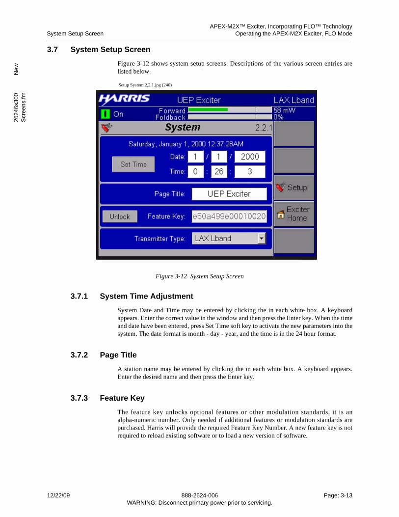
APEX-M2X™ Exciter, Incorporating FLO™ TechnologySystem Setup Screen Operating the APEX-M2X Exciter, FLO Mode
2624
6s3
00
New
Scr
een
s.fm
3.7 System Setup Screen
Figure 3-12 shows system setup screens. Descriptions of the various screen entries arelisted below.
Setup System 2,2,1.jpg (240)
Figure 3-12 System Setup Screen
3.7.1 System Time Adjustment
System Date and Time may be entered by clicking the in each white box. A keyboardappears. Enter the correct value in the window and then press the Enter key. When the timeand date have been entered, press Set Time soft key to activate the new parameters into thesystem. The date format is month - day - year, and the time is in the 24 hour format.
3.7.2 Page Title
A station name may be entered by clicking the in each white box. A keyboard appears.Enter the desired name and then press the Enter key.
3.7.3 Feature Key
The feature key unlocks optional features or other modulation standards, it is analpha-numeric number. Only needed if additional features or modulation standards arepurchased. Harris will provide the required Feature Key Number. A new feature key is notrequired to reload existing software or to load a new version of software.
12/22/09 888-2624-006 Page: 3-13WARNING: Disconnect primary power prior to servicing.
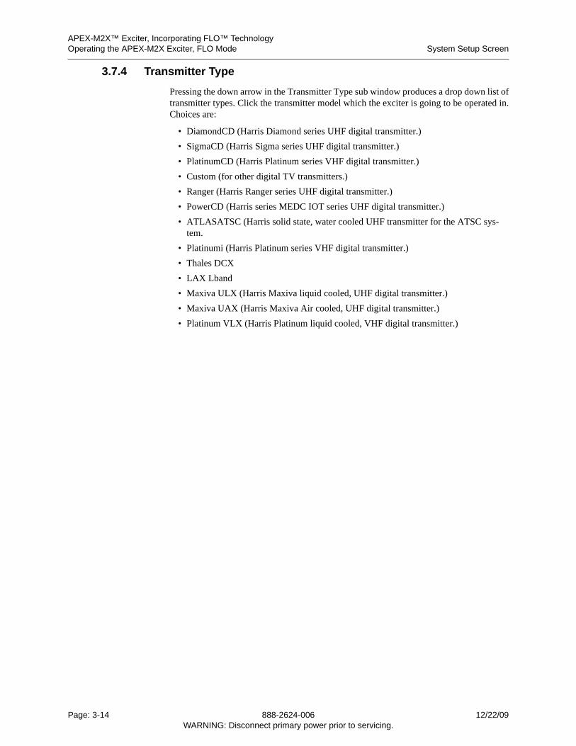
APEX-M2X™ Exciter, Incorporating FLO™ TechnologyOperating the APEX-M2X Exciter, FLO Mode System Setup Screen
3.7.4 Transmitter Type
Pressing the down arrow in the Transmitter Type sub window produces a drop down list oftransmitter types. Click the transmitter model which the exciter is going to be operated in.Choices are:
• DiamondCD (Harris Diamond series UHF digital transmitter.)
• SigmaCD (Harris Sigma series UHF digital transmitter.)
• PlatinumCD (Harris Platinum series VHF digital transmitter.)
• Custom (for other digital TV transmitters.)
• Ranger (Harris Ranger series UHF digital transmitter.)
• PowerCD (Harris series MEDC IOT series UHF digital transmitter.)
• ATLASATSC (Harris solid state, water cooled UHF transmitter for the ATSC sys-tem.
• Platinumi (Harris Platinum series VHF digital transmitter.)
• Thales DCX
• LAX Lband
• Maxiva ULX (Harris Maxiva liquid cooled, UHF digital transmitter.)
• Maxiva UAX (Harris Maxiva Air cooled, UHF digital transmitter.)
• Platinum VLX (Harris Platinum liquid cooled, VHF digital transmitter.)
Page: 3-14 888-2624-006 12/22/09WARNING: Disconnect primary power prior to servicing.
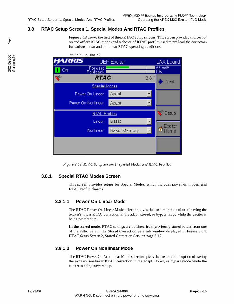
APEX-M2X™ Exciter, Incorporating FLO™ TechnologyRTAC Setup Screen 1, Special Modes And RTAC Profiles Operating the APEX-M2X Exciter, FLO Mode
2624
6s3
00
New
Scr
een
s.fm
3.8 RTAC Setup Screen 1, Special Modes And RTAC Profiles
Figure 3-13 shows the first of three RTAC Setup screens. This screen provides choices foron and off air RTAC modes and a choice of RTAC profiles used to pre load the correctorsfor various linear and nonlinear RTAC operating conditions.
Setup RTAC 2,8,1.jpg (240)
Figure 3-13 RTAC Setup Screen 1, Special Modes and RTAC Profiles
3.8.1 Special RTAC Modes Screen
This screen provides setups for Special Modes, which includes power on modes, andRTAC Profile choices.
3.8.1.1 Power On Linear Mode
The RTAC Power On Linear Mode selection gives the customer the option of having theexciter's linear RTAC correction in the adapt, stored, or bypass mode while the exciter isbeing powered up.
In the stored mode, RTAC settings are obtained from previously stored values from oneof the Filter Sets in the Stored Correction Sets sub window displayed in Figure 3-14,RTAC Setup Screen 2, Stored Correction Sets, on page 3-17.
3.8.1.2 Power On Nonlinear Mode
The RTAC Power On NonLinear Mode selection gives the customer the option of havingthe exciter's nonlinear RTAC correction in the adapt, stored, or bypass mode while theexciter is being powered up.
12/22/09 888-2624-006 Page: 3-15WARNING: Disconnect primary power prior to servicing.
APEX-M2X™ Exciter, Incorporating FLO™ TechnologyOperating the APEX-M2X Exciter, FLO Mode RTAC Setup Screen 1, Special Modes And RTAC Profiles
In the stored mode, RTAC settings are obtained from previously stored values from oneof the Filter Sets in the Stored Correction Sets sub window displayed in Figure 3-14,RTAC Setup Screen 2, Stored Correction Sets, on page 3-17.
3.8.2 RTAC Profiles
The profile choices for linear and non-linear correction are available to coarse tune theRTAC correction to a specific range for a given transmitter system. This will improve theRTAC function.
Profile Linear Change
For linear RTAC correction, BASIC and LONG OFFSET profiles should be tried first. Theleast powerful profile is Basic, with the power increasing down the list until MAX OFFET(the most powerful profile) is reached. The rule of thumb here is that more is not neces-sarily better, so only use as much profile power as is needed. The linear profile choices are:
• BASIC. This correction should be used for most standard mask filters.
• SHORT.
• LONG.
• MAX.
• BASIC OFFSET.
• SHORT OFFSET.
• LONG OFFSET. This correction should be used for sharp tuned mask filters, special mask filters, or when a two or more transmitters of different frequencies are being combined into a single output through 2 or more sharp tuned filters.
• MAX OFFSET
Profile Nonlinear Change
For non-linear RTAC correction, the named profiles should be tried before the numberedprofiles. The least powerful profile is BASIC, with the power increasing down the list untilPROFILE 9 (the most powerful profile) is reached. Most transmitters should use BASIC.or BASIC MEMORY, However, if they do not give satisfactory adjacent channel inter-modulation performance, such as in an IOT transmitter or when OFDM modulation isused, a more powerful profile such as HIGH or HIGH MEMORY should be used. ProfileNonlinear choices are:
• BASIC,
• BASIC MEMORY,
• PROFILE 3,
• PROFILE 4,
• HIGH,
• HIGH MEMORY,
• PROFILE 7,
• PROFILE 8
• PROFILE 9
Page: 3-16 888-2624-006 12/22/09WARNING: Disconnect primary power prior to servicing.
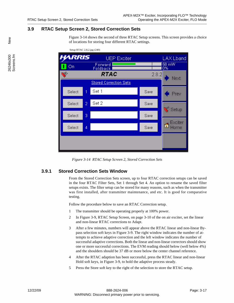
APEX-M2X™ Exciter, Incorporating FLO™ TechnologyRTAC Setup Screen 2, Stored Correction Sets Operating the APEX-M2X Exciter, FLO Mode
2624
6s3
00
New
Scr
een
s.fm
3.9 RTAC Setup Screen 2, Stored Correction Sets
Figure 3-14 shows the second of three RTAC Setup screens. This screen provides a choiceof locations for storing four different RTAC settings.
Setup RTAC 2,8,2.jpg (240)
Figure 3-14 RTAC Setup Screen 2, Stored Correction Sets
3.9.1 Stored Correction Sets Window
From the Stored Correction Sets screen, up to four RTAC correction setups can be savedin the four RTAC Filter Sets, Set 1 through Set 4. An option to rename the saved filtersetups exists. The filter setup can be stored for many reasons, such as when the transmitterwas first installed, after transmitter maintenance, and etc. It is good for comparativetesting.
Follow the procedure below to save an RTAC Correction setup.
1 The transmitter should be operating properly at 100% power.
2 In Figure 3-9, RTAC Setup Screen, on page 3-10 of the on air exciter, set the linear and non-linear RTAC corrections to Adapt.
3 After a few minutes, numbers will appear above the RTAC linear and non-linear By-pass selection soft keys in Figure 3-9. The right window indicates the number of at-tempts to achieve adaptive correction and the left window indicates the number of successful adaptive corrections. Both the linear and non-linear correctors should show one or more successful corrections. The EVM reading should below (well below 4%) and the shoulders should be 37 dB or more below the center channel reference.
4 After the RTAC adaption has been successful, press the RTAC linear and non-linear Hold soft keys, in Figure 3-9, to hold the adaptive process steady.
5 Press the Store soft key to the right of the selection to store the RTAC setup.
12/22/09 888-2624-006 Page: 3-17WARNING: Disconnect primary power prior to servicing.
APEX-M2X™ Exciter, Incorporating FLO™ TechnologyOperating the APEX-M2X Exciter, FLO Mode RTAC Setup Screen 2, Stored Correction Sets
6 The title of the selected filter set can be changed by clicking in the white box of the desired filter set. This brings up an alpha/numeric touch keypad which is used to enter the new name for the filter set.
3.9.1.1 Operate RTAC From A Saved Filter Set
To operate RTAC from a saved filter set, Follow the procedure below.
1 In the Stored Corrections Set screen of Figure 3-15 of the on air exciter, press the Se-lect soft key to the left of the desired correction set.
A That button will turn green.
2 In Figure 3-9, RTAC Setup Screen, on page 3-10 of the on air exciter, press the linear and non-linear RTAC corrections Stored soft key
A RTAC will now be operating on the selected filter set.
Page: 3-18 888-2624-006 12/22/09WARNING: Disconnect primary power prior to servicing.
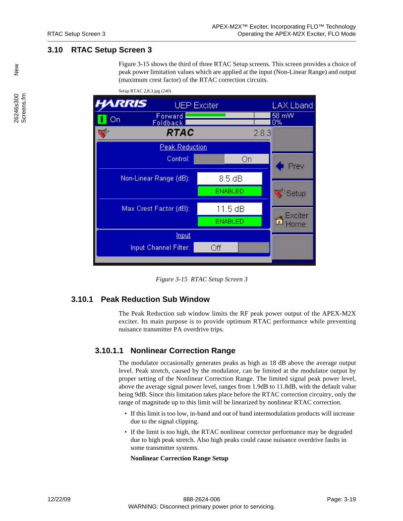
APEX-M2X™ Exciter, Incorporating FLO™ TechnologyRTAC Setup Screen 3 Operating the APEX-M2X Exciter, FLO Mode
2624
6s3
00
New
Scr
een
s.fm
3.10 RTAC Setup Screen 3
Figure 3-15 shows the third of three RTAC Setup screens. This screen provides a choice ofpeak power limitation values which are applied at the input (Non-Linear Range) and output(maximum crest factor) of the RTAC correction circuits.
Setup RTAC 2,8,3.jpg (240)
Figure 3-15 RTAC Setup Screen 3
3.10.1 Peak Reduction Sub Window
The Peak Reduction sub window limits the RF peak power output of the APEX-M2Xexciter. Its main purpose is to provide optimum RTAC performance while preventingnuisance transmitter PA overdrive trips.
3.10.1.1 Nonlinear Correction Range
The modulator occasionally generates peaks as high as 18 dB above the average outputlevel. Peak stretch, caused by the modulator, can be limited at the modulator output byproper setting of the Nonlinear Correction Range. The limited signal peak power level,above the average signal power level, ranges from 1.9dB to 11.8dB, with the default valuebeing 9dB. Since this limitation takes place before the RTAC correction circuitry, only therange of magnitude up to this limit will be linearized by nonlinear RTAC correction.
• If this limit is too low, in-band and out of band intermodulation products will increase due to the signal clipping.
• If the limit is too high, the RTAC nonlinear corrector performance may be degraded due to high peak stretch. Also high peaks could cause nuisance overdrive faults in some transmitter systems.
Nonlinear Correction Range Setup
12/22/09 888-2624-006 Page: 3-19WARNING: Disconnect primary power prior to servicing.
APEX-M2X™ Exciter, Incorporating FLO™ TechnologyOperating the APEX-M2X Exciter, FLO Mode RTAC Setup Screen 3
1. In Figure 3-9, RTAC Setup Screen, on page 3-10, set RTAC Linear and Non-Linear functions to bypass.
2. The exciter RF output should be set to the level required for transmitter opera-tion.
3. In the Figure 3-15, RTAC Peak Reduction screen, set the Peak Reduction Con-trol to Enable.
A The indicator in the Max Peak Stretch sub window of Figure 3-15 will indi-cate Enabled and turn green.
4. In the Figure 3-15, start with the Max Peak Stretch Range at 9dB.
5. Monitor the output of the exciter with a spectrum analyzer and note the adjacent channel intermodulation level.
A The front panel SMA RF output sample connector, behind the front panel door, can be used.
6. lower the Max Peak Stretch Range by 0.5dB intervals and stop when the adjacent channel intermodulation level rises.
A With Both RTAC correctors bypassed, the exciter RF output adjacent chan-nel intermodulation products should be 50dB to 55dB below the in band sig-nal level.
B As the Nonlinear Correction Range value is reduced, in 0.5 dB increments, the first sign of adjacent channel intermodulation product increase will be very subtile, with the first sign often being increased noise in the area just outside the in band channel bandpass.
C If the adjacent channel intermodulation product level rises at the first 0.5dB reduction, try raising the Nonlinear Correction Range value in 0.5 dB incre-ments to see if the shoulder level drops.
7. The correct Nonlinear Correction Range is 0.5dB above the point where the adja-cent channel intermodulation products start to raise.
3.10.1.2 Maximum Crest Factor
The RTAC nonlinear corrector occasionally generates peaks as high as 18 dB above theaverage output level. Therefore, the peak power output from the exciter must be limited inorder to protect the following amplifier stages.
The Max (Maximum) Crest Factor setting limits the peak to average RF output powerratio (7.8 to 17.8 dB) after the RTAC correction circuitry. The default value is 11.5 dB.This directly limits the exciter RF output peak to average power ratio. For example, if themaximum crest factor is set to 10 dB, the exciter will clip any peaks which are greater than10 dB above the average output power level.
• If the limit is set too low, clipping will generate out-of-band intermodulation products in the exciter’s output and may affect the performance of the RTAC non-linear cor-rection.
• If set too high, it could allow nuisance overdrive trips in some transmitter models, be-cause the high amplitude peaks could overdrive the PA modules.
Max Crest Factor Setup
Page: 3-20 888-2624-006 12/22/09WARNING: Disconnect primary power prior to servicing.
APEX-M2X™ Exciter, Incorporating FLO™ TechnologyRTAC Setup Screen 3 Operating the APEX-M2X Exciter, FLO Mode
2624
6s3
00
New
Scr
een
s.fm
It they are occurring, nuisance overdrive trips can be avoided by programming the MaxCrest Factor parameter of the Max Crest Factor sub window of Figure 3-15, the RTACPeak Reduction screen.
Nuisance overdrive trips will typically occur within 30 minutes to 1 hour after transmitteroperation with RTAC is first started. If this happens, perform the following:
1 This setup is preformed with the transmitter operating at full power and RTAC Linear and Non-Linear functions set to Adapt.
2 Start with the Max Crest Factor at 11.5dB.
3 Reduce the Max Crest Factor by 0.25dB.
4 Wait for one hour to see if further overdrive trips occur.
A If they do, reduce the peak stretch by another 0.25 dB.
5 Repeat step 4 until overdrive trips cease.
6 Excessive peak stretch reduction will effect the linearity correction of the transmitter.
A After peak stretch has been adjusted, observe the adjacent channel response to ensure that it still exceed the transmitter output signal mask requirements.
3.10.1.3 Input Channel Filter
Choices are Enabled or Disabled.
This is an IF bandpass filter in the RF Down Converter. It filters out mixing products fromthe down conversion. This filter has a slight frequency response which shows with thelinear correction disabled. For UHF channels with no adjacent channels on the post-filterfeedback, this filter can be disabled. For VHF channels, this filter must be enabled.
12/22/09 888-2624-006 Page: 3-21WARNING: Disconnect primary power prior to servicing.
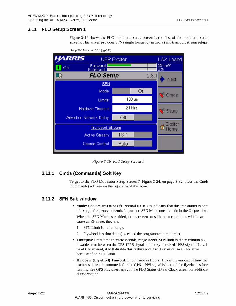
APEX-M2X™ Exciter, Incorporating FLO™ TechnologyOperating the APEX-M2X Exciter, FLO Mode FLO Setup Screen 1
3.11 FLO Setup Screen 1
Figure 3-16 shows the FLO modulator setup screen 1. the first of six modulator setupscreens. This screen provides SFN (single frequency network) and transport stream setups.
Setup FLO Modulator 2,3,1.jpg (240)
Figure 3-16 FLO Setup Screen 1
3.11.1 Cmds (Commands) Soft Key
To get to the FLO Modulator Setup Screen 7, Figure 3-24, on page 3-32, press the Cmds(commands) soft key on the right side of this screen.
3.11.2 SFN Sub window
• Mode: Choices are On or Off. Normal is On. On indicates that this transmitter is part of a single frequency network. Important: SFN Mode must remain in the On position.
When the SFN Mode is enabled, there are two possible error conditions which can cause an RF mute, they are:
1 SFN Limit is out of range.
2 Flywheel has timed out (exceeded the programmed time limit).
• Limit(us): Enter time in microseconds, range 0-999. SFN limit is the maximum al-lowable error between the GPS 1PPS signal and the synthesized 1PPS signal. If a val-ue of 0 is entered, it will disable this feature and it will never cause a SFN error because of an SFN Limit.
• Holdover (Flywheel) Timeout: Enter Time in Hours. This is the amount of time the exciter will remain unmuted after the GPS 1 PPS signal is lost and the flywheel is free running, see GPS FLywheel entry in the FLO Status GPS& Clock screen for addition-al information.
Page: 3-22 888-2624-006 12/22/09WARNING: Disconnect primary power prior to servicing.
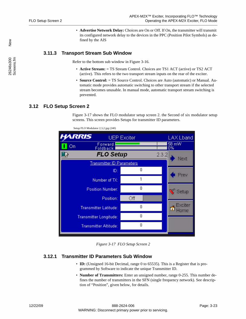
APEX-M2X™ Exciter, Incorporating FLO™ TechnologyFLO Setup Screen 2 Operating the APEX-M2X Exciter, FLO Mode
2624
6s3
00
New
Scr
een
s.fm
• Advertise Network Delay: Choices are On or Off. If On, the transmitter will transmit its configured network delay to the devices in the PPC (Position Pilot Symbols) as de-fined by the AIS
3.11.3 Transport Stream Sub Window
Refer to the bottom sub window in Figure 3-16.
• Active Stream: = TS Stream Control. Choices are TS1 ACT (active) or TS2 ACT (active). This refers to the two transport stream inputs on the rear of the exciter.
• Source Control: = TS Source Control. Choices are Auto (automatic) or Manual. Au-tomatic mode provides automatic switching to other transport stream if the selected stream becomes unusable. In manual mode, automatic transport stream switching is prevented.
3.12 FLO Setup Screen 2
Figure 3-17 shows the FLO modulator setup screen 2. the Second of six modulator setupscreens. This screen provides Setups for transmitter ID parameters.
Setup FLO Modulator 2,3,2.jpg (240)
Figure 3-17 FLO Setup Screen 2
3.12.1 Transmitter ID Parameters Sub Window
• ID: (Unsigned 16-bit Decimal, range 0 to 65535). This is a Register that is pro-grammed by Software to indicate the unique Transmitter ID.
• Number of Transmitters: Enter an unsigned number, range 0-255. This number de-fines the number of transmitters in the SFN (single frequency network). See descrip-tion of “Position”, given below, for details.
12/22/09 888-2624-006 Page: 3-23WARNING: Disconnect primary power prior to servicing.
APEX-M2X™ Exciter, Incorporating FLO™ TechnologyOperating the APEX-M2X Exciter, FLO Mode FLO Setup Screen 3
• Position Number: Enter an unsigned number, range 0-255. This number defines the transmitter position in a chain of transmitters.
Every superframe causes the transmitter number to increment up until it reaches the “Number of Transmitters” shown below. When the increment (current transmitter) number matches “Transmitter position” number, the transmitter becomes the active transmitter
For superframes where the transmitter number is not the same as the “Transmitter po-sition”, the transmitter is inactive (affects PPC (Position Pilot Symbols) only).
Note that “Transmitter position” number (which ranges from 0 to the “Num of Trans-mitters”, entered below) is ignored if the “PPC Insertion” selection is set to disable, see Position Plot in Section 3.15.1, Modulator Parameters Sub Window, on page 3-28.
• Position: Choices are On or Off. If on, the transmitter will transmit its position field information to the devices on the PPC channel.
This entry, when on, would be to open the door to the “Tx Offset Enable” function be-low.
• Transmitter Latitude: The transmitter location (latitude) is entered by the user.
• Transmitter Longitude: The transmitter location (longitude) is entered by the user.
• Transmitter Altitude: The transmitter (antenna) altitude in meters above sea level is entered by the user.
3.13 FLO Setup Screen 3
Figure 3-18 shows the FLO modulator setup screen 3. the third of six modulator setupscreens. This screen provides setups for delays and LOI (Local Area Overhead Informa-tion) insertion.
Page: 3-24 888-2624-006 12/22/09WARNING: Disconnect primary power prior to servicing.
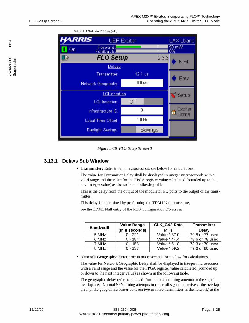
APEX-M2X™ Exciter, Incorporating FLO™ TechnologyFLO Setup Screen 3 Operating the APEX-M2X Exciter, FLO Mode
2624
6s3
00
New
Scr
een
s.fm
Setup FLO Modulator 2,3,3.jpg (240)
Figure 3-18 FLO Setup Screen 3
3.13.1 Delays Sub Window
• Transmitter: Enter time in microseconds, see below for calculations.
The value for Transmitter Delay shall be displayed in integer microseconds with a valid range and the value for the FPGA register value calculated (rounded up to the next integer value) as shown in the following table.
This is the delay from the output of the modulator I/Q ports to the output of the trans-mitter.
This delay is determined by performing the TDM1 Null procedure,
see the TDM1 Null entry of the FLO Configuration 2/5 screen.
• Network Geography: Enter time in microseconds, see below for calculations.
The value for Network Geographic Delay shall be displayed in integer microseconds with a valid range and the value for the FPGA register value calculated (rounded up or down to the next integer value) as shown in the following table.
The geographic delay refers to the path from the transmitting antenna to the signal overlap area. Normal SFN timing attempts to cause all signals to arrive at the overlap area (at the geographic center between two or more transmitters in the network) at the
BandwidthValue Range
(in u seconds)CLK_CX8 Rate
MHzTransmitter
Delay5 MHz 0 - 221 Value * 37.0 79.5 or 77 usec6 MHz 0 - 184 Value * 44.4 78.6 or 78 usec7 MHz 0 - 158 Value * 51.8 78.3 or 79 usec8 MHz 0 - 137 Value * 59.2 77.6 or 80 usec
12/22/09 888-2624-006 Page: 3-25WARNING: Disconnect primary power prior to servicing.
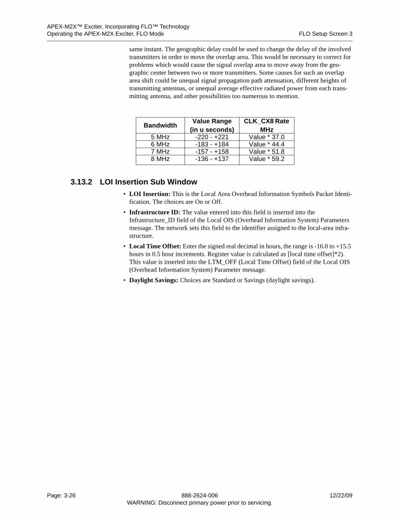
APEX-M2X™ Exciter, Incorporating FLO™ TechnologyOperating the APEX-M2X Exciter, FLO Mode FLO Setup Screen 3
same instant. The geographic delay could be used to change the delay of the involved transmitters in order to move the overlap area. This would be necessary to correct for problems which would cause the signal overlap area to move away from the geo-graphic center between two or more transmitters. Some causes for such an overlap area shift could be unequal signal propagation path attenuation, different heights of transmitting antennas, or unequal average effective radiated power from each trans-mitting antenna, and other possibilities too numerous to mention.
3.13.2 LOI Insertion Sub Window
• LOI Insertion: This is the Local Area Overhead Information Symbols Packet Identi-fication. The choices are On or Off.
• Infrastructure ID: The value entered into this field is inserted into the Infrastructure_ID field of the Local OIS (Overhead Information System) Parameters message. The network sets this field to the identifier assigned to the local-area infra-structure.
• Local Time Offset: Enter the signed real decimal in hours, the range is -16.0 to +15.5 hours in 0.5 hour increments. Register value is calculated as [local time offset]*2). This value is inserted into the LTM_OFF (Local Time Offset) field of the Local OIS (Overhead Information System) Parameter message.
• Daylight Savings: Choices are Standard or Savings (daylight savings).
BandwidthValue Range
(in u seconds)CLK_CX8 Rate
MHz5 MHz -220 - +221 Value * 37.06 MHz -183 - +184 Value * 44.47 MHz -157 - +158 Value * 51.88 MHz -136 - +137 Value * 59.2
Page: 3-26 888-2624-006 12/22/09WARNING: Disconnect primary power prior to servicing.
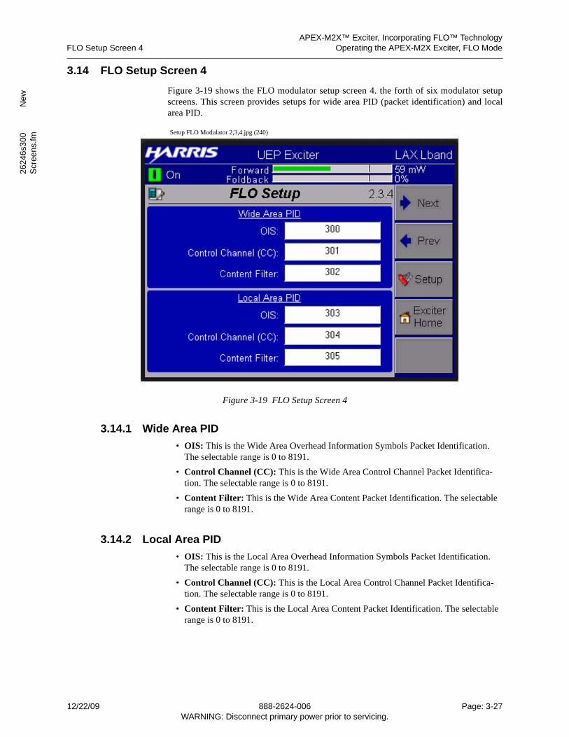
APEX-M2X™ Exciter, Incorporating FLO™ TechnologyFLO Setup Screen 4 Operating the APEX-M2X Exciter, FLO Mode
2624
6s3
00
New
Scr
een
s.fm
3.14 FLO Setup Screen 4
Figure 3-19 shows the FLO modulator setup screen 4. the forth of six modulator setupscreens. This screen provides setups for wide area PID (packet identification) and localarea PID.
Setup FLO Modulator 2,3,4.jpg (240)
Figure 3-19 FLO Setup Screen 4
3.14.1 Wide Area PID
• OIS: This is the Wide Area Overhead Information Symbols Packet Identification. The selectable range is 0 to 8191.
• Control Channel (CC): This is the Wide Area Control Channel Packet Identifica-tion. The selectable range is 0 to 8191.
• Content Filter: This is the Wide Area Content Packet Identification. The selectable range is 0 to 8191.
3.14.2 Local Area PID
• OIS: This is the Local Area Overhead Information Symbols Packet Identification. The selectable range is 0 to 8191.
• Control Channel (CC): This is the Local Area Control Channel Packet Identifica-tion. The selectable range is 0 to 8191.
• Content Filter: This is the Local Area Content Packet Identification. The selectable range is 0 to 8191.
12/22/09 888-2624-006 Page: 3-27WARNING: Disconnect primary power prior to servicing.
APEX-M2X™ Exciter, Incorporating FLO™ TechnologyOperating the APEX-M2X Exciter, FLO Mode FLO Setup Screen 5
3.15 FLO Setup Screen 5
Figure 3-20 shows the FLO modulator setup screen 5. the fifth of six modulator setupscreens. This screen provides setups for modulator parameters.
Setup FLO Modulator 2,3,5.jpg (240)
Figure 3-20 FLO Setup Screen 5
3.15.1 Modulator Parameters Sub Window
3 Position Pilot: Choices are On or Off. On enables the transmitter position field infor-mation on the PPC channel.
On allows the insertion of Position Pilot Symbols (PPCs) at the end of the super-frame. If disabled, these symbol slots may be used for data symbols.
• Slot to Interlace Map: Choices are Mapping 1, Mapping 2, or Mapping 3. This is the data that is inserted into the SPC symbols. Qualcomm has the comment “Refer to AIS for more details on Mapping”.
• Local Symbols Per Frame: This is local area data length.
• Auto Mute: Selection is Off or On. Selecting “Off” causes software to ignore the FPGA RF mute and the SFN Error RF mute. Selecting “On” allows both the FPGA requested RF mute and the SFN Error RF mute to mute the exciter.
The FPGA RF Mute is a mute which is requested by the FPGA. Since this is a Qual-Comm priority circuit, the exact cause of an FPGA RF Mute has not been disclosed.
• WID: Enter a number, unsigned decimal, range 0-15. WID = Wide-area Identifier scrambling value.
• LID: Enter a number, unsigned decimal, range 0-15. LID = Local-area Identifier scrambling value.
Page: 3-28 888-2624-006 12/22/09WARNING: Disconnect primary power prior to servicing.
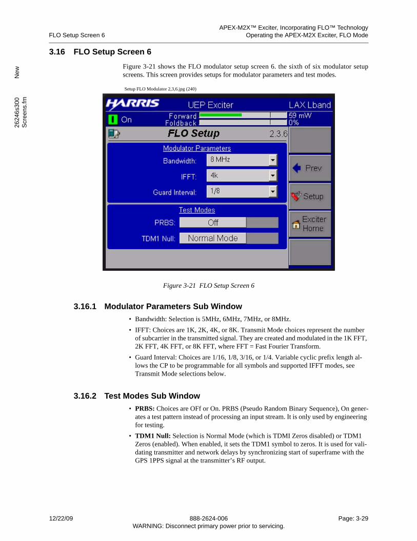
APEX-M2X™ Exciter, Incorporating FLO™ TechnologyFLO Setup Screen 6 Operating the APEX-M2X Exciter, FLO Mode
2624
6s3
00
New
Scr
een
s.fm
3.16 FLO Setup Screen 6
Figure 3-21 shows the FLO modulator setup screen 6. the sixth of six modulator setupscreens. This screen provides setups for modulator parameters and test modes.
Setup FLO Modulator 2,3,6.jpg (240)
Figure 3-21 FLO Setup Screen 6
3.16.1 Modulator Parameters Sub Window
• Bandwidth: Selection is 5MHz, 6MHz, 7MHz, or 8MHz.
• IFFT: Choices are 1K, 2K, 4K, or 8K. Transmit Mode choices represent the number of subcarrier in the transmitted signal. They are created and modulated in the 1K FFT, 2K FFT, 4K FFT, or 8K FFT, where FFT = Fast Fourier Transform.
• Guard Interval: Choices are 1/16, 1/8, 3/16, or 1/4. Variable cyclic prefix length al-lows the CP to be programmable for all symbols and supported IFFT modes, see Transmit Mode selections below.
3.16.2 Test Modes Sub Window
• PRBS: Choices are OFf or On. PRBS (Pseudo Random Binary Sequence), On gener-ates a test pattern instead of processing an input stream. It is only used by engineering for testing.
• TDM1 Null: Selection is Normal Mode (which is TDMI Zeros disabled) or TDM1 Zeros (enabled). When enabled, it sets the TDM1 symbol to zeros. It is used for vali-dating transmitter and network delays by synchronizing start of superframe with the GPS 1PPS signal at the transmitter’s RF output.
12/22/09 888-2624-006 Page: 3-29WARNING: Disconnect primary power prior to servicing.
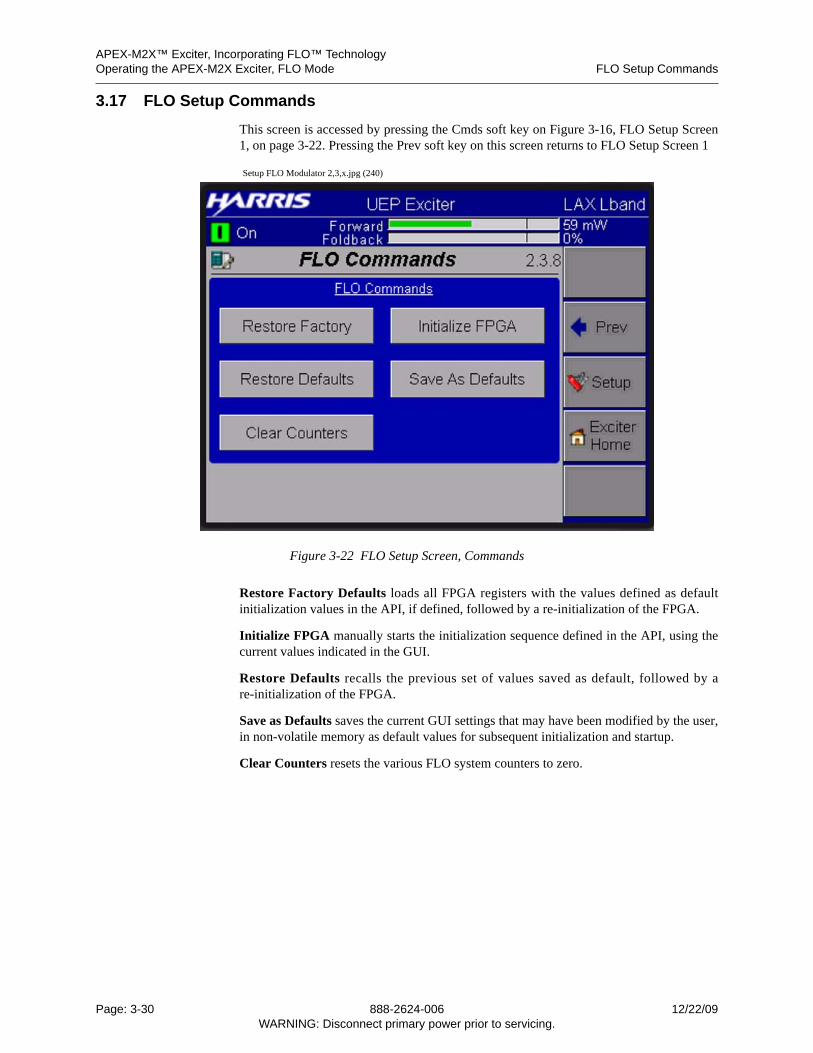
APEX-M2X™ Exciter, Incorporating FLO™ TechnologyOperating the APEX-M2X Exciter, FLO Mode FLO Setup Commands
3.17 FLO Setup Commands
This screen is accessed by pressing the Cmds soft key on Figure 3-16, FLO Setup Screen1, on page 3-22. Pressing the Prev soft key on this screen returns to FLO Setup Screen 1
Setup FLO Modulator 2,3,x.jpg (240)
Figure 3-22 FLO Setup Screen, Commands
Restore Factory Defaults loads all FPGA registers with the values defined as defaultinitialization values in the API, if defined, followed by a re-initialization of the FPGA.
Initialize FPGA manually starts the initialization sequence defined in the API, using thecurrent values indicated in the GUI.
Restore Defaults recalls the previous set of values saved as default, followed by are-initialization of the FPGA.
Save as Defaults saves the current GUI settings that may have been modified by the user,in non-volatile memory as default values for subsequent initialization and startup.
Clear Counters resets the various FLO system counters to zero.
Page: 3-30 888-2624-006 12/22/09WARNING: Disconnect primary power prior to servicing.
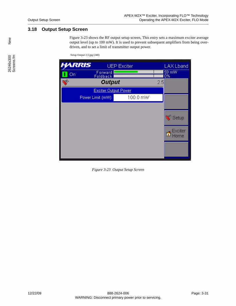
APEX-M2X™ Exciter, Incorporating FLO™ TechnologyOutput Setup Screen Operating the APEX-M2X Exciter, FLO Mode
2624
6s3
00
New
Scr
een
s.fm
3.18 Output Setup Screen
Figure 3-23 shows the RF output setup screen, This entry sets a maximum exciter averageoutput level (up to 100 mW). It is used to prevent subsequent amplifiers from being over-driven, and to set a limit of transmitter output power.
Setup Output 2,5.jpg (240)
Figure 3-23 Output Setup Screen
12/22/09 888-2624-006 Page: 3-31WARNING: Disconnect primary power prior to servicing.
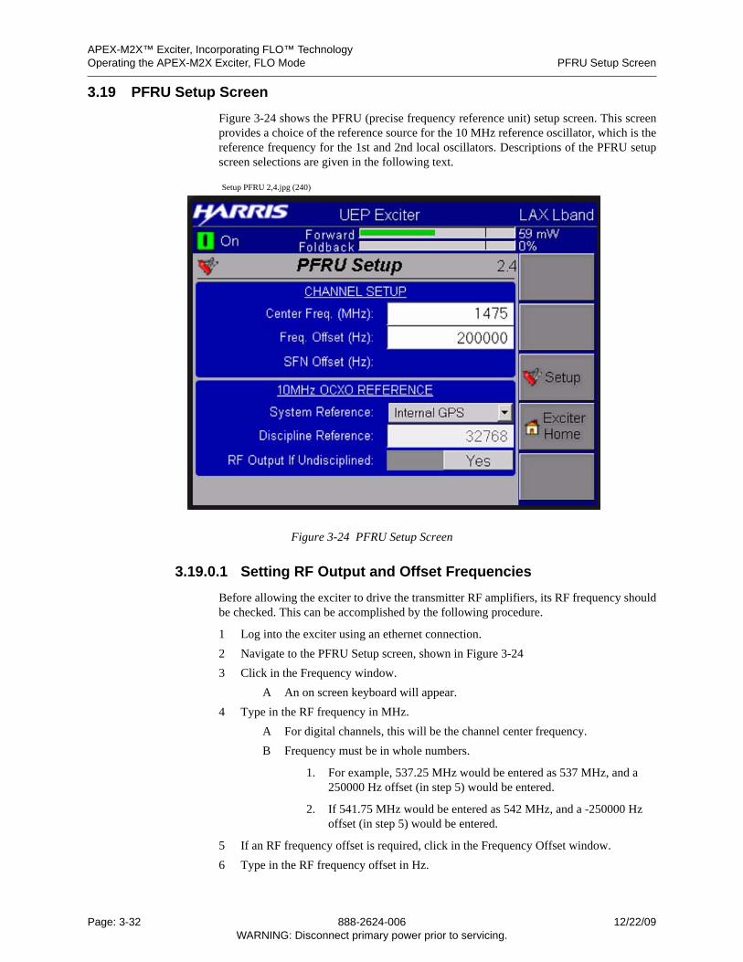
APEX-M2X™ Exciter, Incorporating FLO™ TechnologyOperating the APEX-M2X Exciter, FLO Mode PFRU Setup Screen
3.19 PFRU Setup Screen
Figure 3-24 shows the PFRU (precise frequency reference unit) setup screen. This screenprovides a choice of the reference source for the 10 MHz reference oscillator, which is thereference frequency for the 1st and 2nd local oscillators. Descriptions of the PFRU setupscreen selections are given in the following text.
Setup PFRU 2,4.jpg (240)
Figure 3-24 PFRU Setup Screen
3.19.0.1 Setting RF Output and Offset Frequencies
Before allowing the exciter to drive the transmitter RF amplifiers, its RF frequency shouldbe checked. This can be accomplished by the following procedure.
1 Log into the exciter using an ethernet connection.
2 Navigate to the PFRU Setup screen, shown in Figure 3-24
3 Click in the Frequency window.
A An on screen keyboard will appear.
4 Type in the RF frequency in MHz.
A For digital channels, this will be the channel center frequency.
B Frequency must be in whole numbers.
1. For example, 537.25 MHz would be entered as 537 MHz, and a 250000 Hz offset (in step 5) would be entered.
2. If 541.75 MHz would be entered as 542 MHz, and a -250000 Hz offset (in step 5) would be entered.
5 If an RF frequency offset is required, click in the Frequency Offset window.
6 Type in the RF frequency offset in Hz.
Page: 3-32 888-2624-006 12/22/09WARNING: Disconnect primary power prior to servicing.
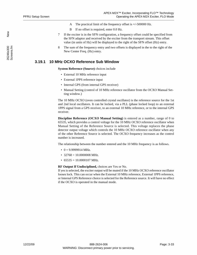
APEX-M2X™ Exciter, Incorporating FLO™ TechnologyPFRU Setup Screen Operating the APEX-M2X Exciter, FLO Mode
2624
6s3
00
New
Scr
een
s.fm
A The practical limit of the frequency offset is +/-500000 Hz.
B If no offset is required, enter 0.0 Hz.
7 If the exciter is in the SFN configuration, a frequency offset could be specified from the SFN adaptor and received by the exciter from the transport stream. This offset value (in units of Hz) will be displayed to the right of the SFN offset (Hz) entry.
8 The sum of the frequency entry and two offsets is displayed in the to the right of the New Center Freq. (Hz) entry.
3.19.1 10 MHz OCXO Reference Sub Window
System Reference (Source) choices include
• External 10 MHz reference input
• External 1PPS reference input
• Internal GPS (from internal GPS receiver)
• Manual Setting (control of 10 MHz reference oscillator from the OCXO Manual Set-ting window.)
The 10 MHz OCXO (oven controlled crystal oscillator) is the reference source for the 1stand 2nd local oscillators. It can be locked, via a PLL (phase locked loop) to an external1PPS signal from a GPS receiver, to an external 10 MHz reference, or to the internal GPSreceiver.
Discipline Reference (OCXO Manual Setting) is entered as a number, range of 0 to65535, which provides a control voltage for the 10 MHz OCXO reference oscillator whenManual Setting of the Reference Source is selected. This voltage replaces the phasedetector output voltage which controls the 10 MHz OCXO reference oscillator when anyof the other Reference Source is selected. The OCXO frequency increases as the controlnumber is increased.
The relationship between the number entered and the 10 MHz frequency is as follows.
• 0 = 9.9999914 MHz.
• 32768 = 10.0000008 MHz.
• 65535 = 10.0000107 MHz.
RF Output If Undisciplined, choices are Yes or No.If yes is selected, the exciter output will be muted if the 10 MHz OCXO reference oscillatorlooses lock. This can occur when the External 10 MHz reference, External 1PPS reference,or Internal GPS Reference choice is selected for the Reference source. It will have no effectif the OCXO is operated in the manual mode.
12/22/09 888-2624-006 Page: 3-33WARNING: Disconnect primary power prior to servicing.
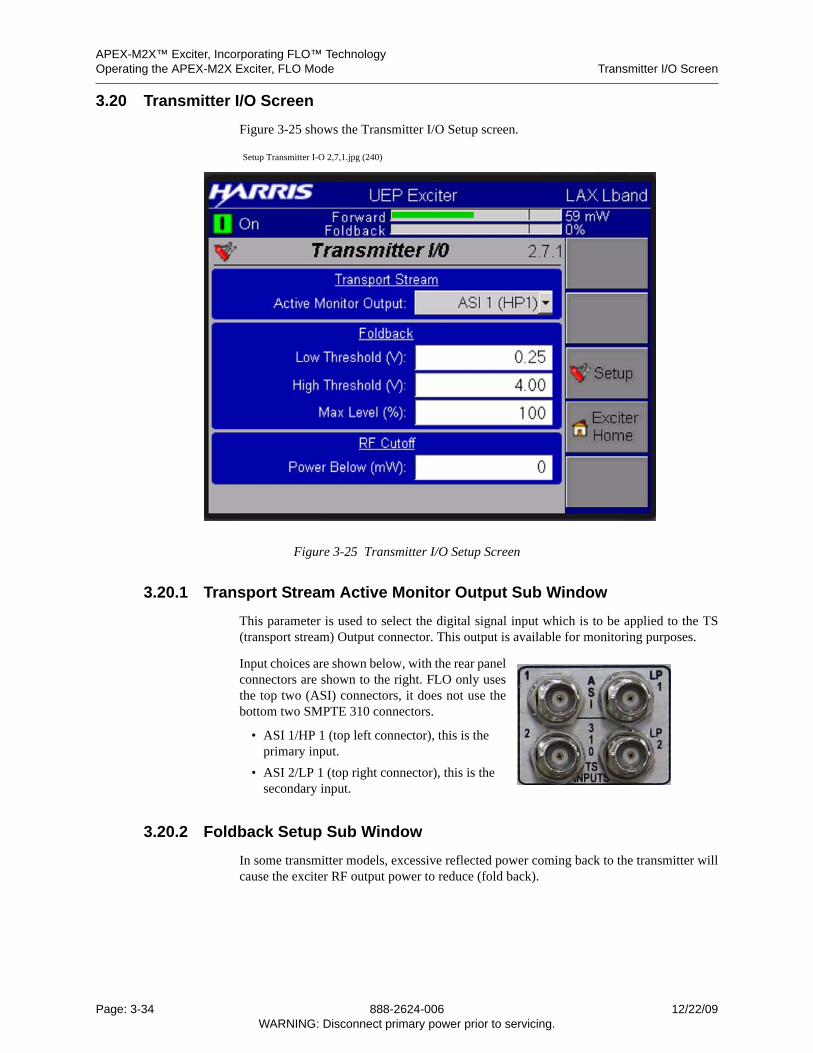
APEX-M2X™ Exciter, Incorporating FLO™ TechnologyOperating the APEX-M2X Exciter, FLO Mode Transmitter I/O Screen
3.20 Transmitter I/O Screen
Figure 3-25 shows the Transmitter I/O Setup screen.
Setup Transmitter I-O 2,7,1.jpg (240)
Figure 3-25 Transmitter I/O Setup Screen
3.20.1 Transport Stream Active Monitor Output Sub Window
This parameter is used to select the digital signal input which is to be applied to the TS(transport stream) Output connector. This output is available for monitoring purposes.
Input choices are shown below, with the rear panelconnectors are shown to the right. FLO only usesthe top two (ASI) connectors, it does not use thebottom two SMPTE 310 connectors.
• ASI 1/HP 1 (top left connector), this is the primary input.
• ASI 2/LP 1 (top right connector), this is the secondary input.
3.20.2 Foldback Setup Sub Window
In some transmitter models, excessive reflected power coming back to the transmitter willcause the exciter RF output power to reduce (fold back).
Page: 3-34 888-2624-006 12/22/09WARNING: Disconnect primary power prior to servicing.
APEX-M2X™ Exciter, Incorporating FLO™ TechnologyTransmitter I/O Screen Operating the APEX-M2X Exciter, FLO Mode
2624
6s3
00
New
Scr
een
s.fm
The Foldback (VSWR foldback setup) low and high thresholds, and the max F/B levelsetups listed below are used when the exciter RF output power control is used to control theRF output power of the transmitter. The Diamond and Platinum TV series transmitters aretwo which fall into this category.
The foldback parameters are entered by clicking in the appropriate box. A touch screenkeyboard appears and the values are entered on that keyboard. When all values have beenentered, touch the Apply soft key to activate the new values.
The VSWR foldback voltage comes from the transmitter control logic and enters theexciter via the Transmitter I/O Board on pin 12 of the bottom rear panel (Transmitter Inter-face) 25 Pin Male connector. The input voltage range is 0 to +5 Vdc and is shown on theTransmitter I/O 1 screen. The VSWR foldback voltage is shown in Figure 3-39, Trans-mitter I/O Status Screen, on page 3-53, and additional information is given in Section3.33.2, Foldback Input Voltage, on page 3-53.
3.20.2.1 F/B Low Thresh
This is the voltage threshold (0 to 5 vdc range) at which RF output power foldback (RFoutput power reduction) first starts. It is typically set at 0.25 volts to prevent DAC noisefrom triggering an RF output power reduction (foldback). Refer to the transmitter technicalmanual for setup instructions for this parameter.
3.20.2.2 F/B High Thresh
This is the voltage threshold (0 to 5 vdc range) at which maximum RF output powerfoldback occurs. It is typically set between 4 or 5 volts, determined by the transmitterpower control logic. Refer to the transmitter technical manual for setup instructions for thisparameter.
3.20.2.3 Max F/B Level
This is the maximum amount of exciter RF output power reduction allowed, range is 0% to100%. It occurs when the VSWR foldback high threshold, listed above, is reached. Itallows the transmitter power amplifier(s) to operate at a safe, reduced output power levelwhen maximum VSWR occurs. Refer to the transmitter technical manual for setup instruc-tions for this parameter.
3.20.3 RF Cutoff Sub Window
When the exciter RF output level (in percent) is reduced to the value displayed here, itcauses the transmitter control logic to switch to the backup exciter. The programable rangeis 0% to 100%. This switch is prevented if the backup exciter is faulted.
12/22/09 888-2624-006 Page: 3-35WARNING: Disconnect primary power prior to servicing.
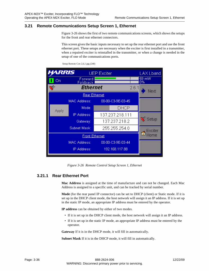
APEX-M2X™ Exciter, Incorporating FLO™ TechnologyOperating the APEX-M2X Exciter, FLO Mode Remote Communications Setup Screen 1, Ethernet
3.21 Remote Communications Setup Screen 1, Ethernet
Figure 3-26 shows the first of two remote communications screens, which shows the setupsfor the front and rear ethernet connectors.
This screen gives the basic inputs necessary to set up the rear ethernet port and use the frontethernet port. These setups are necessary when the exciter is first installed in a transmitter,when a repaired exciter is reinstalled in the transmitter, or when a change is needed in thesetup of one of the communications ports.
Setup Remote Con 2,6,1.jpg (240)
Figure 3-26 Remote Control Setup Screen 1, Ethernet
3.21.1 Rear Ethernet Port
Mac Address is assigned at the time of manufacture and can not be changed. Each MacAddress is assigned to a specific unit, and can be tracked by serial number.
Mode (for the rear panel IP connector) can be set to DHCP (client) or Static mode. If it isset up in the DHCP client mode, the host network will assign it an IP address. If it is set upin the static IP mode, an appropriate IP address must be entered by the operator.
IP address can be obtained by either of two modes.
• If it is set up in the DHCP client mode, the host network will assign it an IP address.
• If it is set up in the static IP mode, an appropriate IP address must be entered by the operator.
Gateway If it is in the DHCP mode, it will fill in automatically.
Subnet Mask If it is in the DHCP mode, it will fill in automatically.
Page: 3-36 888-2624-006 12/22/09WARNING: Disconnect primary power prior to servicing.
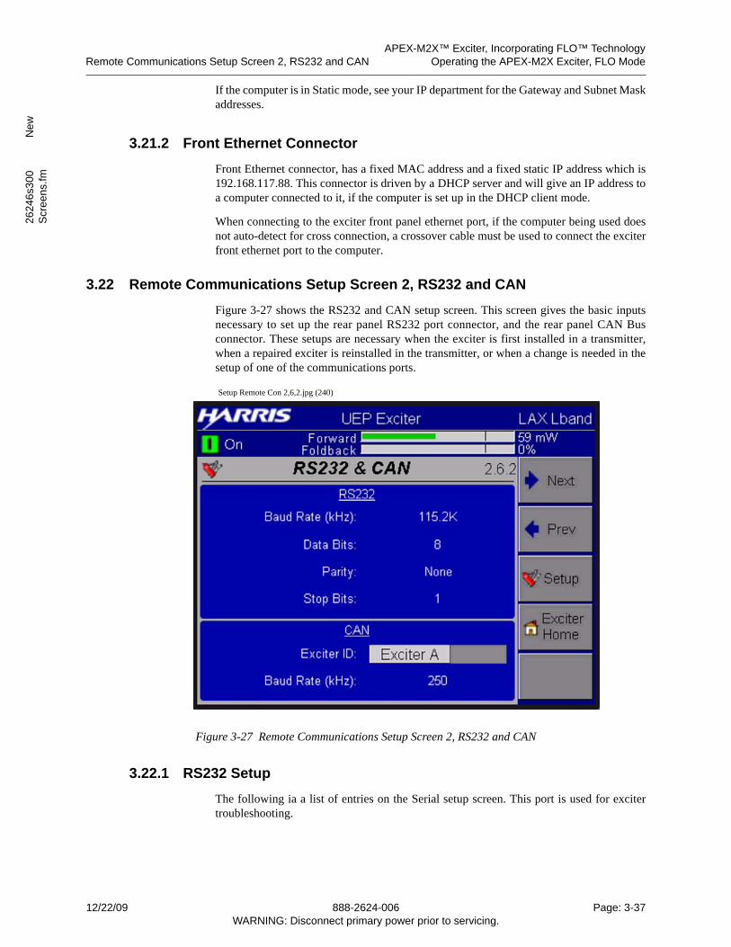
APEX-M2X™ Exciter, Incorporating FLO™ TechnologyRemote Communications Setup Screen 2, RS232 and CAN Operating the APEX-M2X Exciter, FLO Mode
2624
6s3
00
New
Scr
een
s.fm
If the computer is in Static mode, see your IP department for the Gateway and Subnet Maskaddresses.
3.21.2 Front Ethernet Connector
Front Ethernet connector, has a fixed MAC address and a fixed static IP address which is192.168.117.88. This connector is driven by a DHCP server and will give an IP address toa computer connected to it, if the computer is set up in the DHCP client mode.
When connecting to the exciter front panel ethernet port, if the computer being used doesnot auto-detect for cross connection, a crossover cable must be used to connect the exciterfront ethernet port to the computer.
3.22 Remote Communications Setup Screen 2, RS232 and CAN
Figure 3-27 shows the RS232 and CAN setup screen. This screen gives the basic inputsnecessary to set up the rear panel RS232 port connector, and the rear panel CAN Busconnector. These setups are necessary when the exciter is first installed in a transmitter,when a repaired exciter is reinstalled in the transmitter, or when a change is needed in thesetup of one of the communications ports.
Setup Remote Con 2,6,2.jpg (240)
Figure 3-27 Remote Communications Setup Screen 2, RS232 and CAN
3.22.1 RS232 Setup
The following ia a list of entries on the Serial setup screen. This port is used for excitertroubleshooting.
12/22/09 888-2624-006 Page: 3-37WARNING: Disconnect primary power prior to servicing.
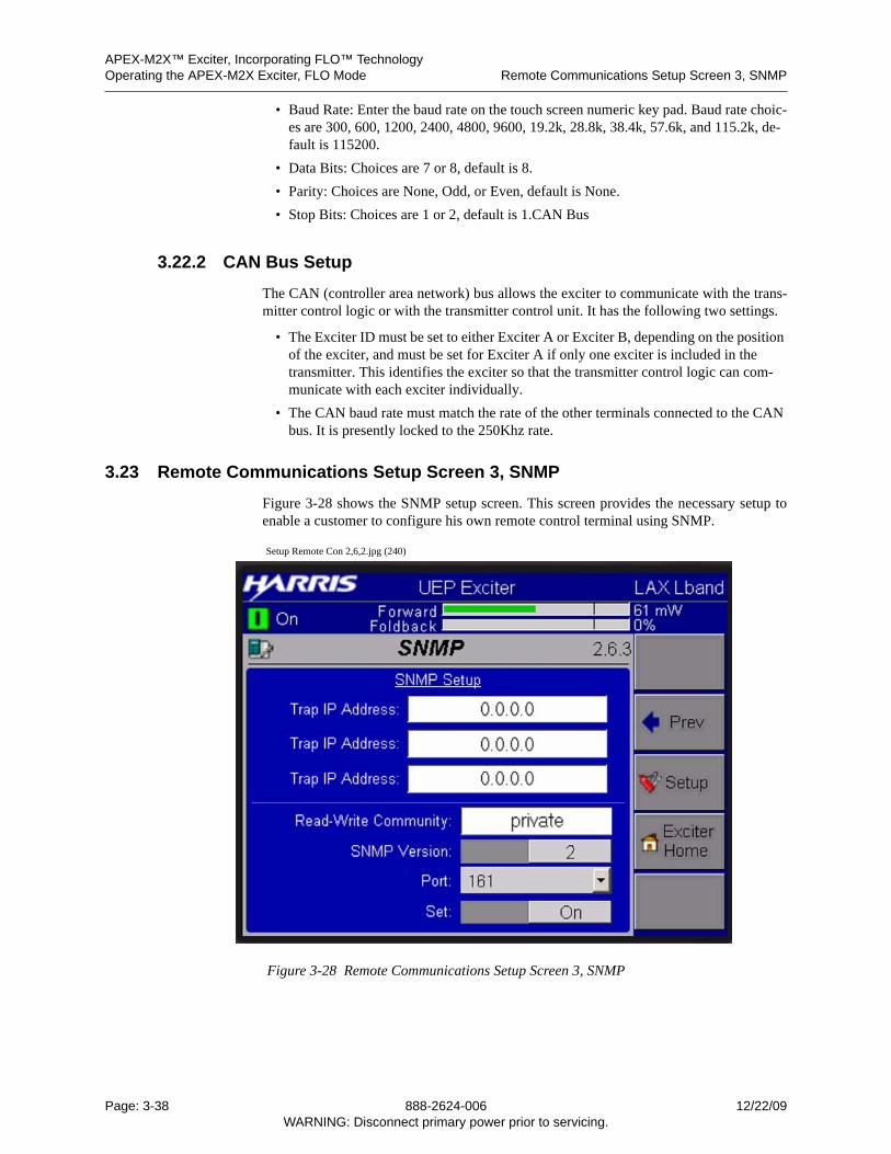
APEX-M2X™ Exciter, Incorporating FLO™ TechnologyOperating the APEX-M2X Exciter, FLO Mode Remote Communications Setup Screen 3, SNMP
• Baud Rate: Enter the baud rate on the touch screen numeric key pad. Baud rate choic-es are 300, 600, 1200, 2400, 4800, 9600, 19.2k, 28.8k, 38.4k, 57.6k, and 115.2k, de-fault is 115200.
• Data Bits: Choices are 7 or 8, default is 8.
• Parity: Choices are None, Odd, or Even, default is None.
• Stop Bits: Choices are 1 or 2, default is 1.CAN Bus
3.22.2 CAN Bus Setup
The CAN (controller area network) bus allows the exciter to communicate with the trans-mitter control logic or with the transmitter control unit. It has the following two settings.
• The Exciter ID must be set to either Exciter A or Exciter B, depending on the position of the exciter, and must be set for Exciter A if only one exciter is included in the transmitter. This identifies the exciter so that the transmitter control logic can com-municate with each exciter individually.
• The CAN baud rate must match the rate of the other terminals connected to the CAN bus. It is presently locked to the 250Khz rate.
3.23 Remote Communications Setup Screen 3, SNMP
Figure 3-28 shows the SNMP setup screen. This screen provides the necessary setup toenable a customer to configure his own remote control terminal using SNMP.
Setup Remote Con 2,6,2.jpg (240)
Figure 3-28 Remote Communications Setup Screen 3, SNMP
Page: 3-38 888-2624-006 12/22/09WARNING: Disconnect primary power prior to servicing.
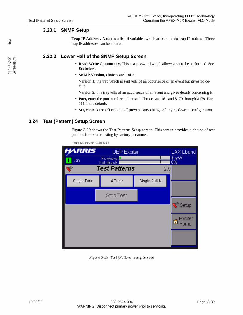
APEX-M2X™ Exciter, Incorporating FLO™ TechnologyTest (Pattern) Setup Screen Operating the APEX-M2X Exciter, FLO Mode
2624
6s3
00
New
Scr
een
s.fm
3.23.1 SNMP Setup
Trap IP Address. A trap is a list of variables which are sent to the trap IP address. Threetrap IP addresses can be entered.
3.23.2 Lower Half of the SNMP Setup Screen
• Read-Write Community, This is a password which allows a set to be performed. See Set below.
• SNMP Version, choices are 1 of 2.
Version 1: the trap which is sent tells of an occurrence of an event but gives no de-tails.
Version 2: this trap tells of an occurrence of an event and gives details concerning it.
• Port, enter the port number to be used. Choices are 161 and 8170 through 8179. Port 161 is the default.
• Set, choices are Off or On. Off prevents any change of any read/write configuration.
3.24 Test (Pattern) Setup Screen
Figure 3-29 shows the Test Patterns Setup screen. This screen provides a choice of testpatterns for exciter testing by factory personnel.
Setup Test Patterns 2,9.jpg (240)
Figure 3-29 Test (Pattern) Setup Screen
12/22/09 888-2624-006 Page: 3-39WARNING: Disconnect primary power prior to servicing.
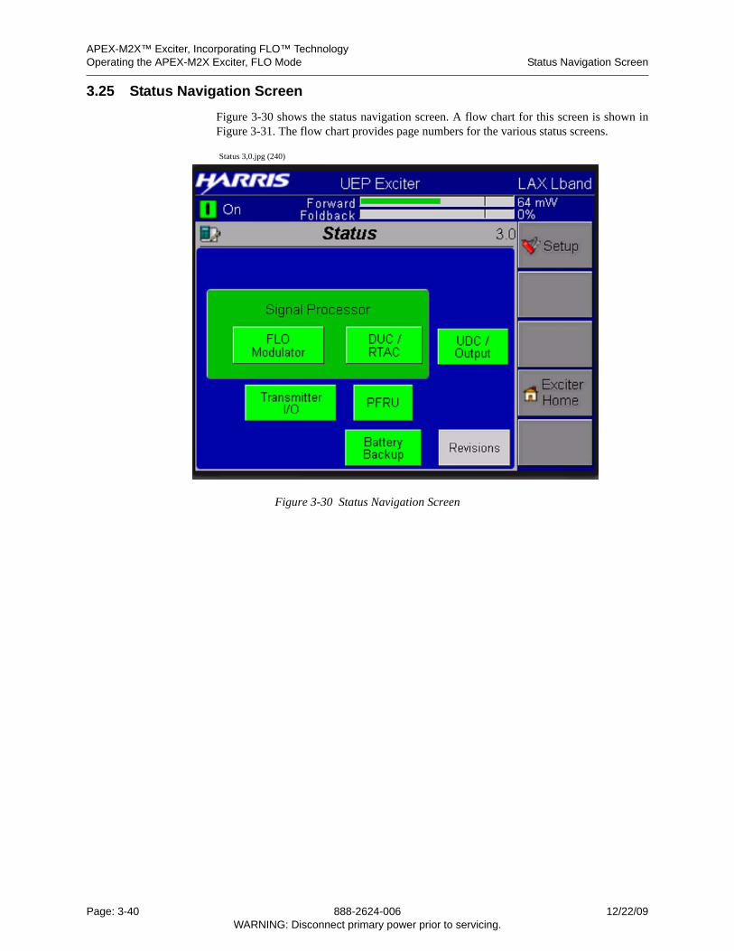
APEX-M2X™ Exciter, Incorporating FLO™ TechnologyOperating the APEX-M2X Exciter, FLO Mode Status Navigation Screen
3.25 Status Navigation Screen
Figure 3-30 shows the status navigation screen. A flow chart for this screen is shown inFigure 3-31. The flow chart provides page numbers for the various status screens.
Status 3,0.jpg (240)
Figure 3-30 Status Navigation Screen
Page: 3-40 888-2624-006 12/22/09WARNING: Disconnect primary power prior to servicing.
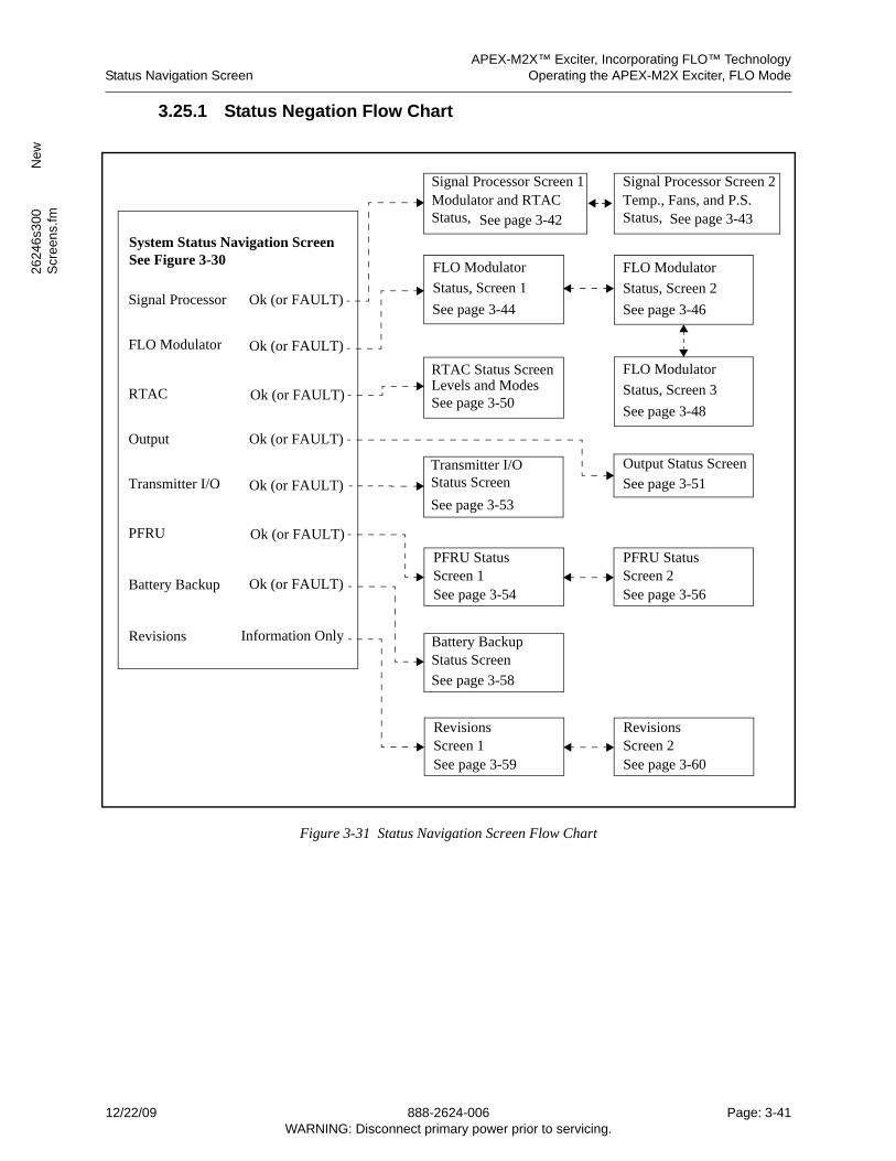
APEX-M2X™ Exciter, Incorporating FLO™ TechnologyStatus Navigation Screen Operating the APEX-M2X Exciter, FLO Mode
2624
6s3
00
New
Scr
een
s.fm
3.25.1 Status Negation Flow Chart
Figure 3-31 Status Navigation Screen Flow Chart
Signal Processor Ok (or FAULT)
FLO Modulator Ok (or FAULT)
Ok (or FAULT)Battery Backup
FLO Modulator
Status, Screen 1
Ok (or FAULT)RTAC
Battery BackupStatus Screen
PFRU StatusScreen 1
RTAC Status ScreenLevels and Modes
System Status Navigation ScreenSee Figure 3-30
See page 3-44
See page 3-50
See page 3-54
See page 3-58
Transmitter I/O Output Status Screen
See page 3-51
See page 3-53
Status Screen
Output Ok (or FAULT)
Transmitter I/O Ok (or FAULT)
Ok (or FAULT)PFRU
FLO Modulator
Status, Screen 2
See page 3-46
Signal Processor Screen 1
See page 3-42Modulator and RTAC
Signal Processor Screen 2
See page 3-43Temp., Fans, and P.S.
Status, Status,
PFRU StatusScreen 2See page 3-56
FLO Modulator
Status, Screen 3
See page 3-48
Information OnlyRevisions
RevisionsScreen 1See page 3-59
RevisionsScreen 2See page 3-60
12/22/09 888-2624-006 Page: 3-41WARNING: Disconnect primary power prior to servicing.
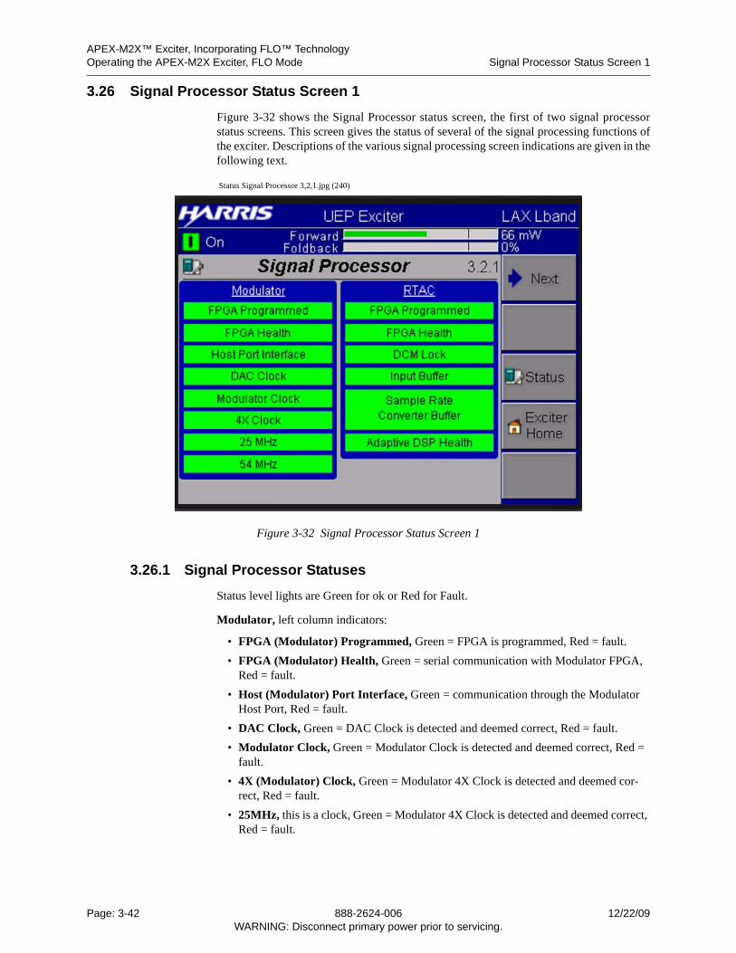
APEX-M2X™ Exciter, Incorporating FLO™ TechnologyOperating the APEX-M2X Exciter, FLO Mode Signal Processor Status Screen 1
3.26 Signal Processor Status Screen 1
Figure 3-32 shows the Signal Processor status screen, the first of two signal processorstatus screens. This screen gives the status of several of the signal processing functions ofthe exciter. Descriptions of the various signal processing screen indications are given in thefollowing text.
Status Signal Processor 3,2,1.jpg (240)
Figure 3-32 Signal Processor Status Screen 1
3.26.1 Signal Processor Statuses
Status level lights are Green for ok or Red for Fault.
Modulator, left column indicators:
• FPGA (Modulator) Programmed, Green = FPGA is programmed, Red = fault.
• FPGA (Modulator) Health, Green = serial communication with Modulator FPGA, Red = fault.
• Host (Modulator) Port Interface, Green = communication through the Modulator Host Port, Red = fault.
• DAC Clock, Green = DAC Clock is detected and deemed correct, Red = fault.
• Modulator Clock, Green = Modulator Clock is detected and deemed correct, Red = fault.
• 4X (Modulator) Clock, Green = Modulator 4X Clock is detected and deemed cor-rect, Red = fault.
• 25MHz, this is a clock, Green = Modulator 4X Clock is detected and deemed correct, Red = fault.
Page: 3-42 888-2624-006 12/22/09WARNING: Disconnect primary power prior to servicing.
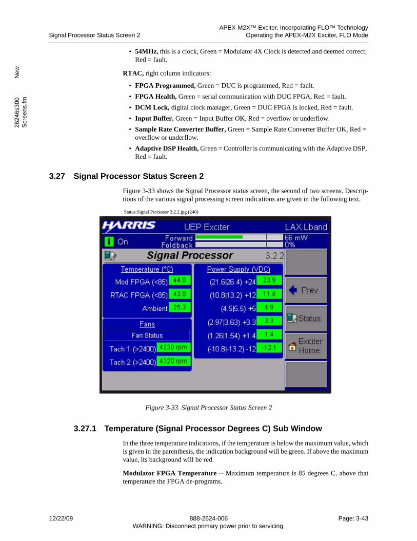
APEX-M2X™ Exciter, Incorporating FLO™ TechnologySignal Processor Status Screen 2 Operating the APEX-M2X Exciter, FLO Mode
2624
6s3
00
New
Scr
een
s.fm
• 54MHz, this is a clock, Green = Modulator 4X Clock is detected and deemed correct, Red = fault.
RTAC, right column indicators:
• FPGA Programmed, Green = DUC is programmed, Red = fault.
• FPGA Health, Green = serial communication with DUC FPGA, Red = fault.
• DCM Lock, digital clock manager, Green = DUC FPGA is locked, Red = fault.
• Input Buffer, Green = Input Buffer OK, Red = overflow or underflow.
• Sample Rate Converter Buffer, Green = Sample Rate Converter Buffer OK, Red = overflow or underflow.
• Adaptive DSP Health, Green = Controller is communicating with the Adaptive DSP, Red = fault.
3.27 Signal Processor Status Screen 2
Figure 3-33 shows the Signal Processor status screen, the second of two screens. Descrip-tions of the various signal processing screen indications are given in the following text.
Status Signal Processor 3.2.2.jpg (240)
Figure 3-33 Signal Processor Status Screen 2
3.27.1 Temperature (Signal Processor Degrees C) Sub Window
In the three temperature indications, if the temperature is below the maximum value, whichis given in the parenthesis, the indication background will be green. If above the maximumvalue, its background will be red.
Modulator FPGA Temperature -- Maximum temperature is 85 degrees C, above thattemperature the FPGA de-programs.
12/22/09 888-2624-006 Page: 3-43WARNING: Disconnect primary power prior to servicing.
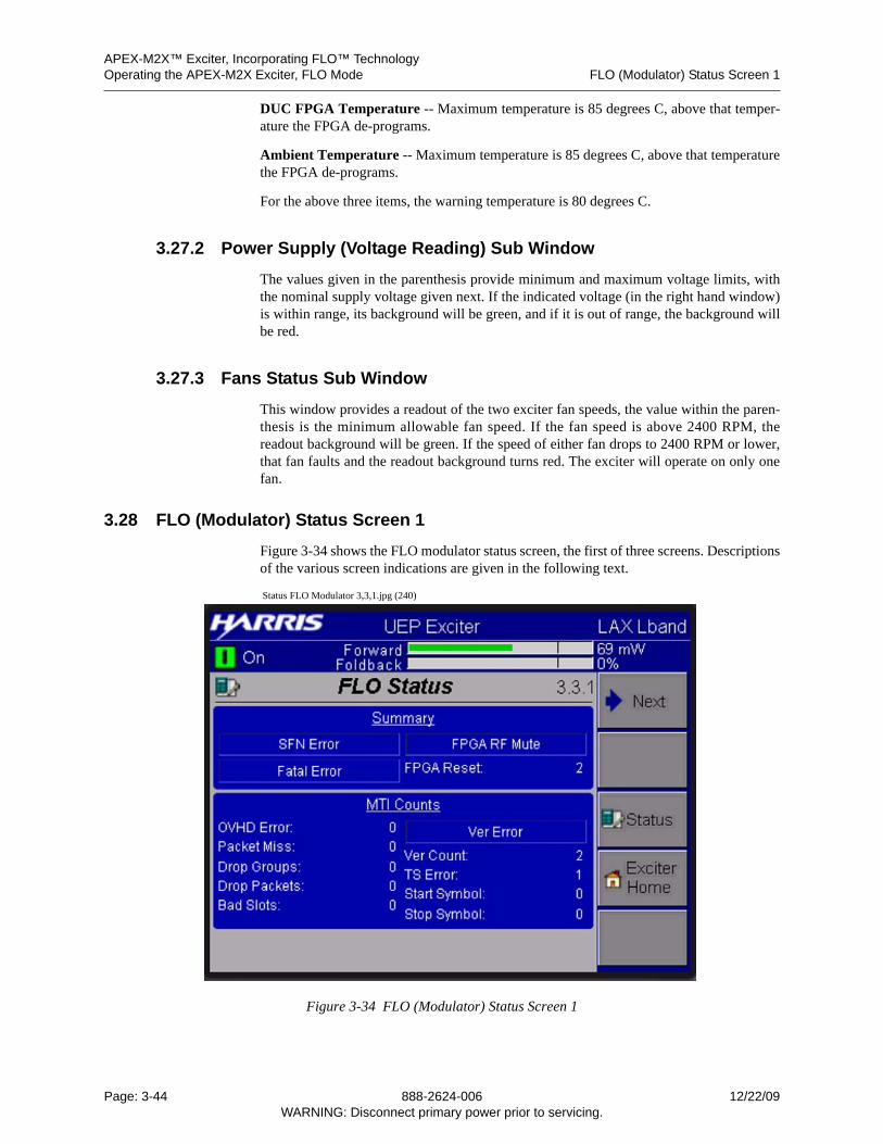
APEX-M2X™ Exciter, Incorporating FLO™ TechnologyOperating the APEX-M2X Exciter, FLO Mode FLO (Modulator) Status Screen 1
DUC FPGA Temperature -- Maximum temperature is 85 degrees C, above that temper-ature the FPGA de-programs.
Ambient Temperature -- Maximum temperature is 85 degrees C, above that temperaturethe FPGA de-programs.
For the above three items, the warning temperature is 80 degrees C.
3.27.2 Power Supply (Voltage Reading) Sub Window
The values given in the parenthesis provide minimum and maximum voltage limits, withthe nominal supply voltage given next. If the indicated voltage (in the right hand window)is within range, its background will be green, and if it is out of range, the background willbe red.
3.27.3 Fans Status Sub Window
This window provides a readout of the two exciter fan speeds, the value within the paren-thesis is the minimum allowable fan speed. If the fan speed is above 2400 RPM, thereadout background will be green. If the speed of either fan drops to 2400 RPM or lower,that fan faults and the readout background turns red. The exciter will operate on only onefan.
3.28 FLO (Modulator) Status Screen 1
Figure 3-34 shows the FLO modulator status screen, the first of three screens. Descriptionsof the various screen indications are given in the following text.
Status FLO Modulator 3,3,1.jpg (240)
Figure 3-34 FLO (Modulator) Status Screen 1
Page: 3-44 888-2624-006 12/22/09WARNING: Disconnect primary power prior to servicing.
APEX-M2X™ Exciter, Incorporating FLO™ TechnologyFLO (Modulator) Status Screen 1 Operating the APEX-M2X Exciter, FLO Mode
2624
6s3
00
New
Scr
een
s.fm
3.28.1 Summary Sub Window
• SFN Error: Blue = OK, Red = error. If SFN (single frequency network) is enabled, an SFN error occurs If:
1 The SFN buffer has an overflow or underflow.
2 An SFN sequence error occurs.
3 An SFN parity error occurs
• Fatal Error: Blue = OK, Red = error.
• RF Mute: Blue = OK, Red = error.
• FPGA Reset: This is an indication of the number of times the FPGA has been reset.
3.28.2 MTI Sub Window
This window has 10 status entries, which are as follows:
• OVHD Err: Displayed as an integer decimal. Overhead Error Count indicates the number of MAC data or OIS descriptor packets that were found to have illegal over-head data. The turbogroups associated with these error packets are dropped (i.e., not written into PLC memories).
• Packet Miss: Displayed as an integer decimal. This counter will increment if packets are dropped upstream for any reason or if packet ordering is not maintained.
• Drop Groups: Displayed as an integer decimal. Dropped Groups indicate the number of groups that were dropped since the last reset, due to the mpeg transport error bit be-ing set in an OIS or MAC group descriptor packet. The entire OIS group (6 mpeg packets) or the entire MAC group (3 mpeg packets) will be dropped if the transport error bit is set for the OIS descriptor packet or the MAC descriptor packet, respective-ly.
• Drop Packets: Displayed as an integer decimal. This display indicates the number of MAC data packets that were dropped since the last reset, due to the mpeg transport er-ror bit being set or due to an MTI version mismatch (see MTI_VERS_TS_ERR) reg-ister.
• Bad Slot: Displayed as a hexadecimal number. Refer to Table 3-1 for Bad Slot Bit list.
Table 3-1 Bad Slot Bit List
Bit Name Description
19-16 PKT_ID The packet ID value of the last descriptor packet found to have illegal data. (2=OIS, 4=DATA)
15-12 MLC_MODE The MediaFLO Logical Channel (MLC) mode of the last de-scriptor packet found to have illegal data.
11-8 SLOT_OFFSET The slot offset value of the last descriptor packet found to have illegal data.
7-4 MAX_SLOT The maximum slot value of the last descriptor packet found to have illegal data.
3-0 MIN_SLOT The minimum slot value of the last descriptor packet found to have illegal data.
12/22/09 888-2624-006 Page: 3-45WARNING: Disconnect primary power prior to servicing.
APEX-M2X™ Exciter, Incorporating FLO™ TechnologyOperating the APEX-M2X Exciter, FLO Mode FLO (Modulator) Status Screen 2
• Ver Error: Blue = OK, Red = error. When lit red, it indicates a mismatch between the MTI (Multiplex Subsystem to Transmit Subsystem Interface) hardware version and the version received in the transport stream. Each occurrence of a mismatch caus-es the packet to be dropped before entering the SFN buffer as well as causing MTI_PKT_MISS_CNT to increment.
• Ver Error Count: Displayed as an integer decimal. The Version Error status is polled once per second. If a Version Error is detected, the counter increments.
• TS Error This entry counts the number of bad packets received since the last time this entry was cleared. This entry is cleared by using the Clear Counters choice on the FLO Commands screen, Figure 3-22, on page 3-30.
• Start Symbol: Displayed as an integer decimal. This is the start symbol value of the last descriptor packet found to have illegal data.
• Stop Symbol: Displayed as an integer decimal. This is the stop symbol value of the last descriptor packet found to have illegal data.
3.29 FLO (Modulator) Status Screen 2
Figure 3-35 shows the FLO modulator status screen, the second of three screens. Descrip-tions of the various screen indications are given in the following text.
Status FLO Modulator 3,3,2.jpg (240)
Figure 3-35 FLO (Modulator) Status Screen 2
3.29.1 Transport Stream Sub Window
• Active Stream: Indicates the active transport stream (TS 1 Active or TS 2 Active). This indication tells which transport stream input is being used, regardless if the transport stream is present at it input.
Page: 3-46 888-2624-006 12/22/09WARNING: Disconnect primary power prior to servicing.
APEX-M2X™ Exciter, Incorporating FLO™ TechnologyFLO (Modulator) Status Screen 2 Operating the APEX-M2X Exciter, FLO Mode
2624
6s3
00
New
Scr
een
s.fm
The active transport stream selection is determined by the TS Stream Control and TSSource Control selections found in section Section 3.11.3, Transport Stream Sub Window,on page 3-23.
3.29.2 ASI 1 and ASI 2 Sub Windows
• Sync (ASI 1) Detection: Sync ASI 2 Detection:
Green = transport stream present and active, Yellow = transport stream present and inactive,Red = transport stream missing.
• TS1 Buffer: TS2 Buffer:
Conditions are OK (green background) or OOF (red background)
• TS1 OOF Count: TS2 OOF Count:
OOF = Out Of Frame. This happens when two consecutive LOFs (loss-of-frame) oc-cur. Once seven good frames are received, OOF returns to normal.
• TS1 Packet Rate: TS2 Packet Rate:
Packet Rate: = The raw packet rate for the incoming transport stream, including null packets. For FLO, all mpeg packets are 188 bytes.
3.29.3 Wide Packet Rates
• OIS = the number of wide overhead information symbol packets received between the two most recent GPA 1PPS pulses.
• Control Channel = the number of wide content packets received between the two most recent GPA 1PPS pulses.
• Content = the number of wide control channel packets received between the two most recent GPA 1PPS pulses.
3.29.4 Local Packet Rates
• OIS = the number of local overhead information symbol packets received between the two most recent GPA 1PPS pulses.
• Control Channel = the number of local control channel packets received between the two most recent GPA 1PPS pulses.
• Content = the number of local content packets received between the two most recent GPA 1PPS pulses.
12/22/09 888-2624-006 Page: 3-47WARNING: Disconnect primary power prior to servicing.
APEX-M2X™ Exciter, Incorporating FLO™ TechnologyOperating the APEX-M2X Exciter, FLO Mode FLO (Modulator) Status Screen 3
3.30 FLO (Modulator) Status Screen 3
Figure 3-36 shows the FLO modulator status screen, the third of three screens. ThisDescriptions of the various screen indications are given in the following text.
Status FLO Modulator 3,3,3.jpg (240)
Figure 3-36 FLO (Modulator) Status Screen 3
3.30.0.1 Timing Status, GPS & Clock Status Functions
•Holdover: Displayed as Hours: Minutes: Seconds. Holdover will show the Flywheel free running operating time. When this time is equal to or greater than the “Flywheel Timeout” field entry (shown in the FLO Configuration 2/5 screen) the exciter will mute.
The Holdover window will indicate “Disciplining” when the GPS 1PPS signal returns and the generated 1PPS signal is in the process of locking to it. during this time, the GPS Flywheel light will be yellow.
When lock is achieved, the Holdover window will indicate 00:00:00 hours and the GPS Flywheel light will be green.
• SSF Arrival: displayed in milliseconds. SSF = Start of Superframe. The displayed value indicates the time from the occurrence of the GPS 1PPS to the start of the super-frame indicator.
• Timing Drift refers to Ave Frequency Error. This is the timing error (in microsec-onds) between the synthesized 1PPS signal and the GPS 1PPS signal. This number should be 6.4 microseconds or less when the two signals are locked together, the GPS Flywheel is said to be operational and locked, and the Flywheel indicator will be green.
Page: 3-48 888-2624-006 12/22/09WARNING: Disconnect primary power prior to servicing.
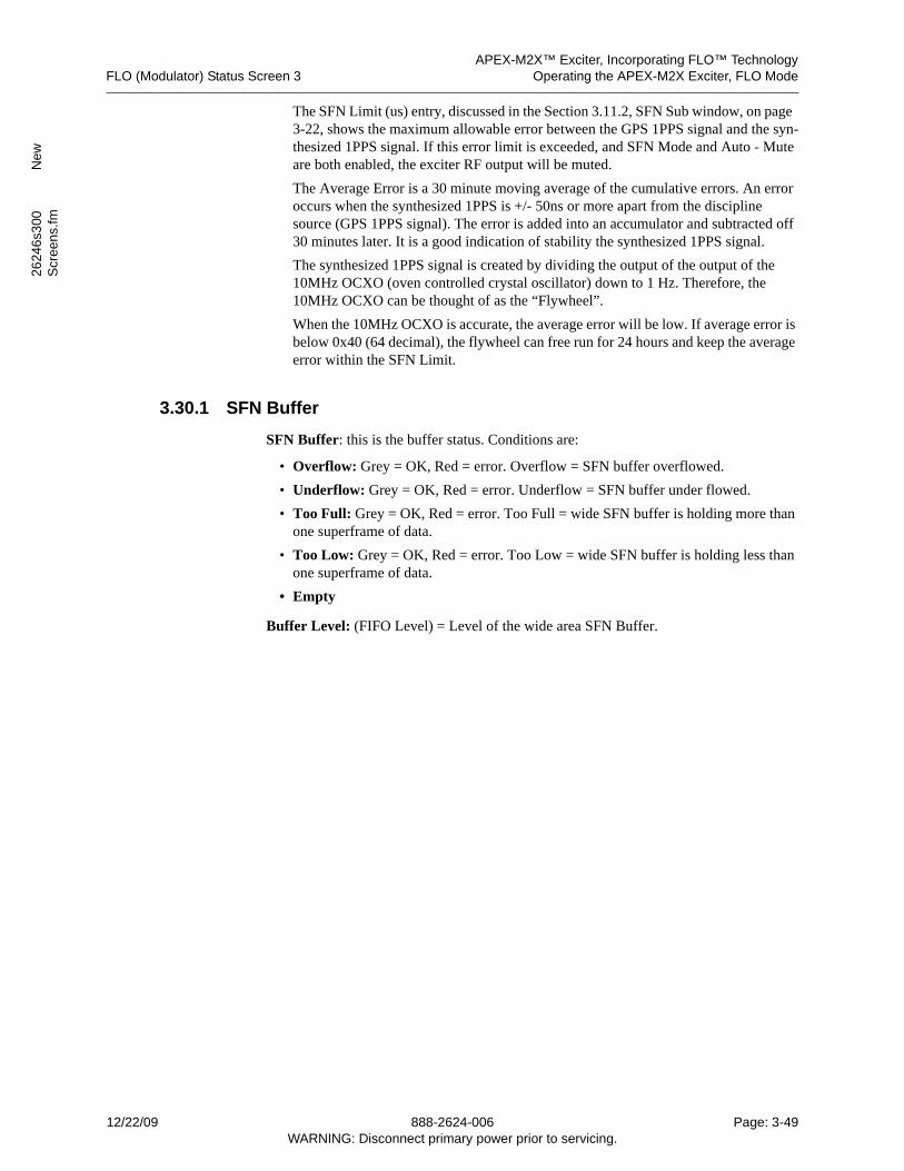
APEX-M2X™ Exciter, Incorporating FLO™ TechnologyFLO (Modulator) Status Screen 3 Operating the APEX-M2X Exciter, FLO Mode
2624
6s3
00
New
Scr
een
s.fm
The SFN Limit (us) entry, discussed in the Section 3.11.2, SFN Sub window, on page 3-22, shows the maximum allowable error between the GPS 1PPS signal and the syn-thesized 1PPS signal. If this error limit is exceeded, and SFN Mode and Auto - Mute are both enabled, the exciter RF output will be muted.
The Average Error is a 30 minute moving average of the cumulative errors. An error occurs when the synthesized 1PPS is +/- 50ns or more apart from the discipline source (GPS 1PPS signal). The error is added into an accumulator and subtracted off 30 minutes later. It is a good indication of stability the synthesized 1PPS signal.
The synthesized 1PPS signal is created by dividing the output of the output of the 10MHz OCXO (oven controlled crystal oscillator) down to 1 Hz. Therefore, the 10MHz OCXO can be thought of as the “Flywheel”.
When the 10MHz OCXO is accurate, the average error will be low. If average error is below 0x40 (64 decimal), the flywheel can free run for 24 hours and keep the average error within the SFN Limit.
3.30.1 SFN Buffer
SFN Buffer: this is the buffer status. Conditions are:
• Overflow: Grey = OK, Red = error. Overflow = SFN buffer overflowed.
• Underflow: Grey = OK, Red = error. Underflow = SFN buffer under flowed.
• Too Full: Grey = OK, Red = error. Too Full = wide SFN buffer is holding more than one superframe of data.
• Too Low: Grey = OK, Red = error. Too Low = wide SFN buffer is holding less than one superframe of data.
• Empty
Buffer Level: (FIFO Level) = Level of the wide area SFN Buffer.
12/22/09 888-2624-006 Page: 3-49WARNING: Disconnect primary power prior to servicing.
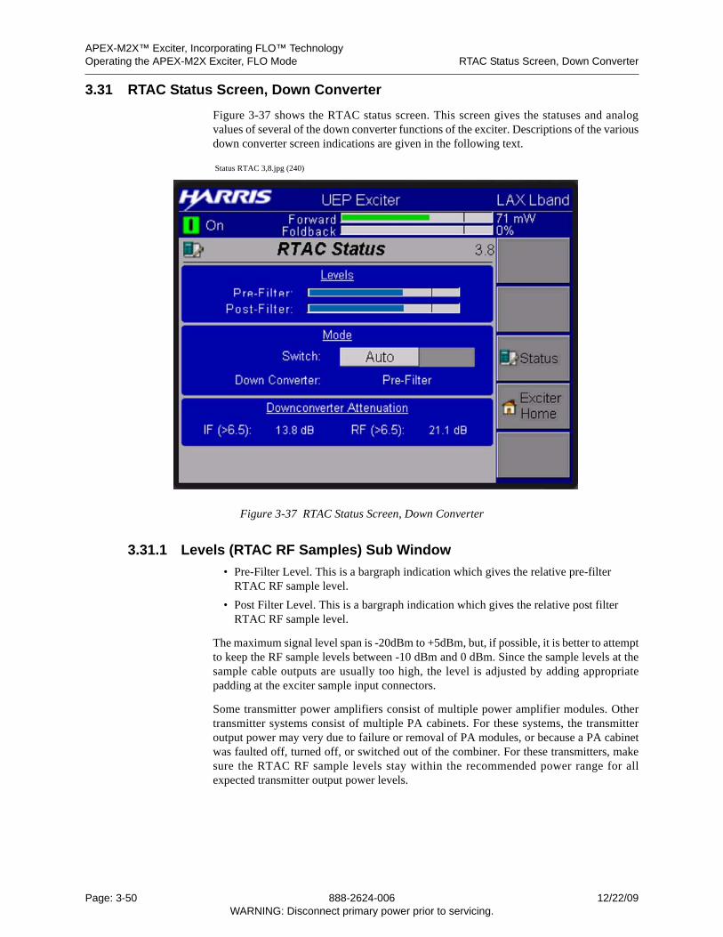
APEX-M2X™ Exciter, Incorporating FLO™ TechnologyOperating the APEX-M2X Exciter, FLO Mode RTAC Status Screen, Down Converter
3.31 RTAC Status Screen, Down Converter
Figure 3-37 shows the RTAC status screen. This screen gives the statuses and analogvalues of several of the down converter functions of the exciter. Descriptions of the variousdown converter screen indications are given in the following text.
Status RTAC 3,8.jpg (240)
Figure 3-37 RTAC Status Screen, Down Converter
3.31.1 Levels (RTAC RF Samples) Sub Window
• Pre-Filter Level. This is a bargraph indication which gives the relative pre-filter RTAC RF sample level.
• Post Filter Level. This is a bargraph indication which gives the relative post filter RTAC RF sample level.
The maximum signal level span is -20dBm to +5dBm, but, if possible, it is better to attemptto keep the RF sample levels between -10 dBm and 0 dBm. Since the sample levels at thesample cable outputs are usually too high, the level is adjusted by adding appropriatepadding at the exciter sample input connectors.
Some transmitter power amplifiers consist of multiple power amplifier modules. Othertransmitter systems consist of multiple PA cabinets. For these systems, the transmitteroutput power may very due to failure or removal of PA modules, or because a PA cabinetwas faulted off, turned off, or switched out of the combiner. For these transmitters, makesure the RTAC RF sample levels stay within the recommended power range for allexpected transmitter output power levels.
Page: 3-50 888-2624-006 12/22/09WARNING: Disconnect primary power prior to servicing.
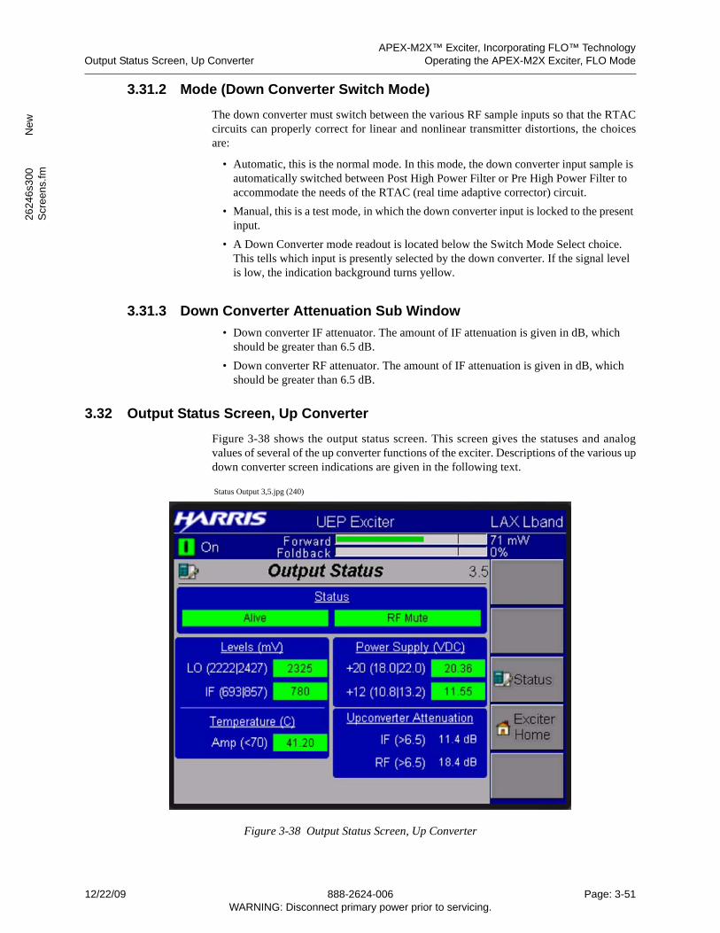
APEX-M2X™ Exciter, Incorporating FLO™ TechnologyOutput Status Screen, Up Converter Operating the APEX-M2X Exciter, FLO Mode
2624
6s3
00
New
Scr
een
s.fm
3.31.2 Mode (Down Converter Switch Mode)
The down converter must switch between the various RF sample inputs so that the RTACcircuits can properly correct for linear and nonlinear transmitter distortions, the choicesare:
• Automatic, this is the normal mode. In this mode, the down converter input sample is automatically switched between Post High Power Filter or Pre High Power Filter to accommodate the needs of the RTAC (real time adaptive corrector) circuit.
• Manual, this is a test mode, in which the down converter input is locked to the present input.
• A Down Converter mode readout is located below the Switch Mode Select choice. This tells which input is presently selected by the down converter. If the signal level is low, the indication background turns yellow.
3.31.3 Down Converter Attenuation Sub Window
• Down converter IF attenuator. The amount of IF attenuation is given in dB, which should be greater than 6.5 dB.
• Down converter RF attenuator. The amount of IF attenuation is given in dB, which should be greater than 6.5 dB.
3.32 Output Status Screen, Up Converter
Figure 3-38 shows the output status screen. This screen gives the statuses and analogvalues of several of the up converter functions of the exciter. Descriptions of the various updown converter screen indications are given in the following text.
Status Output 3,5.jpg (240)
Figure 3-38 Output Status Screen, Up Converter
12/22/09 888-2624-006 Page: 3-51WARNING: Disconnect primary power prior to servicing.
APEX-M2X™ Exciter, Incorporating FLO™ TechnologyOperating the APEX-M2X Exciter, FLO Mode Output Status Screen, Up Converter
3.32.1 Status Sub Window
The status sub window, top of output status screen, has two indication, which are:
• Alive, Green = UDC is communicating, Red is fault.
• RF Mute, plain = unmuted, Red = muted.
3.32.2 Levels (mV)
This sub window provides the signal levels, ambient temperature, and dc supply voltagesfor the up converter. These parameters are as follows:
• LO Level (in mV), range is 2222 to 2427.
• IF Level (in mV), range is 693 to 857.
3.32.3 Temperature (C)
• Amp (amplifier) Temp. A temperature fault occurs at 70 degrees C.
3.32.4 Power Supply (VDC)
• +12VDC -- This reading has no limits, it should be within 10% of the stated value.
• +20VDC -- This reading has no limits, it should be within 10% of the stated value.
3.32.5 Up Converter Attenuation
• Up converter IF attenuator. The amount of IF attenuation is represented by the dis-played value, which must be greater than 6.5 dB.
• Up converter RF attenuator. The amount of RF attenuation is represented by the dis-played value, which must be greater than 6.5 dB.
Page: 3-52 888-2624-006 12/22/09WARNING: Disconnect primary power prior to servicing.
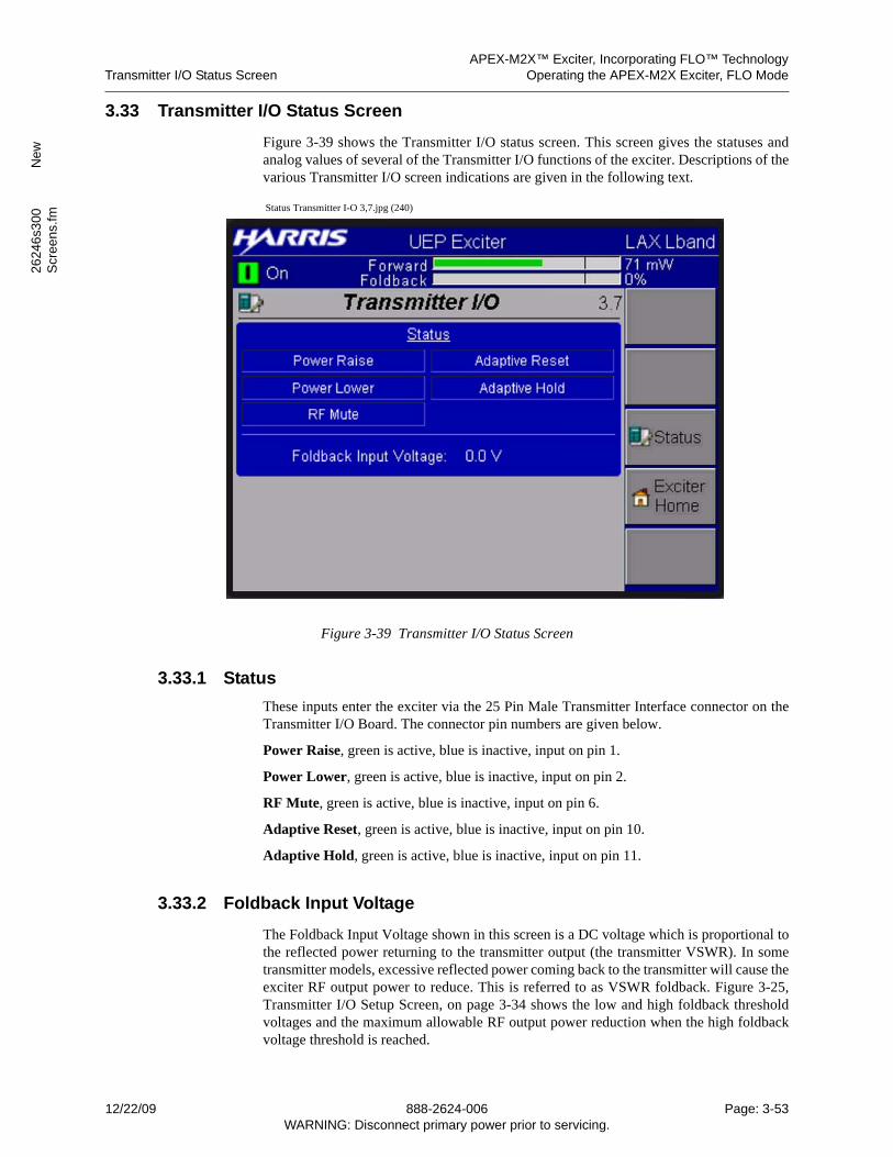
APEX-M2X™ Exciter, Incorporating FLO™ TechnologyTransmitter I/O Status Screen Operating the APEX-M2X Exciter, FLO Mode
2624
6s3
00
New
Scr
een
s.fm
3.33 Transmitter I/O Status Screen
Figure 3-39 shows the Transmitter I/O status screen. This screen gives the statuses andanalog values of several of the Transmitter I/O functions of the exciter. Descriptions of thevarious Transmitter I/O screen indications are given in the following text.
Status Transmitter I-O 3,7.jpg (240)
Figure 3-39 Transmitter I/O Status Screen
3.33.1 Status
These inputs enter the exciter via the 25 Pin Male Transmitter Interface connector on theTransmitter I/O Board. The connector pin numbers are given below.
Power Raise, green is active, blue is inactive, input on pin 1.
Power Lower, green is active, blue is inactive, input on pin 2.
RF Mute, green is active, blue is inactive, input on pin 6.
Adaptive Reset, green is active, blue is inactive, input on pin 10.
Adaptive Hold, green is active, blue is inactive, input on pin 11.
3.33.2 Foldback Input Voltage
The Foldback Input Voltage shown in this screen is a DC voltage which is proportional tothe reflected power returning to the transmitter output (the transmitter VSWR). In sometransmitter models, excessive reflected power coming back to the transmitter will cause theexciter RF output power to reduce. This is referred to as VSWR foldback. Figure 3-25,Transmitter I/O Setup Screen, on page 3-34 shows the low and high foldback thresholdvoltages and the maximum allowable RF output power reduction when the high foldbackvoltage threshold is reached.
12/22/09 888-2624-006 Page: 3-53WARNING: Disconnect primary power prior to servicing.
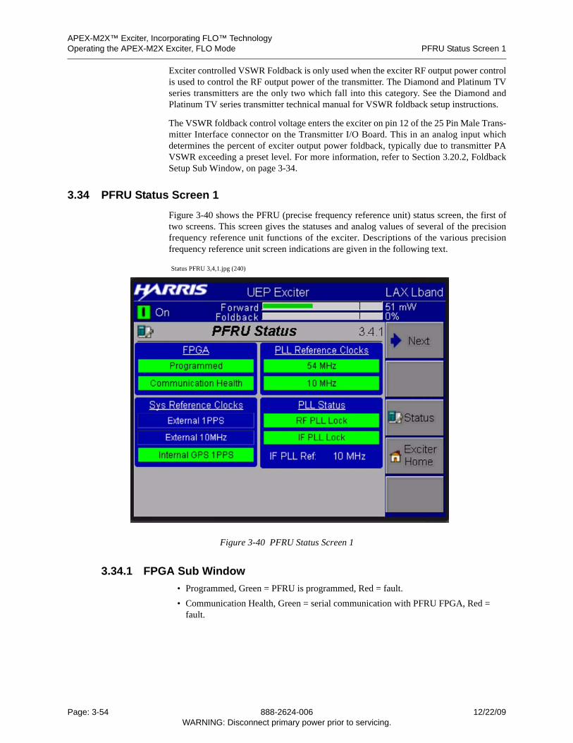
APEX-M2X™ Exciter, Incorporating FLO™ TechnologyOperating the APEX-M2X Exciter, FLO Mode PFRU Status Screen 1
Exciter controlled VSWR Foldback is only used when the exciter RF output power controlis used to control the RF output power of the transmitter. The Diamond and Platinum TVseries transmitters are the only two which fall into this category. See the Diamond andPlatinum TV series transmitter technical manual for VSWR foldback setup instructions.
The VSWR foldback control voltage enters the exciter on pin 12 of the 25 Pin Male Trans-mitter Interface connector on the Transmitter I/O Board. This in an analog input whichdetermines the percent of exciter output power foldback, typically due to transmitter PAVSWR exceeding a preset level. For more information, refer to Section 3.20.2, FoldbackSetup Sub Window, on page 3-34.
3.34 PFRU Status Screen 1
Figure 3-40 shows the PFRU (precise frequency reference unit) status screen, the first oftwo screens. This screen gives the statuses and analog values of several of the precisionfrequency reference unit functions of the exciter. Descriptions of the various precisionfrequency reference unit screen indications are given in the following text.
Status PFRU 3,4,1.jpg (240)
Figure 3-40 PFRU Status Screen 1
3.34.1 FPGA Sub Window
• Programmed, Green = PFRU is programmed, Red = fault.
• Communication Health, Green = serial communication with PFRU FPGA, Red = fault.
Page: 3-54 888-2624-006 12/22/09WARNING: Disconnect primary power prior to servicing.
APEX-M2X™ Exciter, Incorporating FLO™ TechnologyPFRU Status Screen 1 Operating the APEX-M2X Exciter, FLO Mode
2624
6s3
00
New
Scr
een
s.fm
3.34.2 System Reference CLocks Sub Window
• External 1PPS, Present = green background. This input is derived from the custom-er’s GPS receiver.
• External 10 MHz, Present = green background. This input can be derived from a va-riety of sources.
• Internal GPS 1PPS, Present = green background. This signal is derived from the ex-citer’s internal GPS receiver.
3.34.3 PLL Reference Clocks Sub Window
• 54MHz: This is an internal clock on the processor board, and used to derive the other system clocks. It is 2 times the 27MHz clock used for ASI. Green = OK, Red = fault.
• 10MHz: This is an internal clock used to synchronize the phase lock loops in the pre-cise frequency reference unit (PFRU). Green = OK, Red = fault.
3.34.4 PLL Status Sub Window
• RF LO PLL Lock: This reference output from this circuit is used by the up converter to set the exciter output to the correct frequency and is used by the down converter to heterodyne the RF output samples back to the IF frequency. Green = OK, Red = fault.
• IF LO PLL Lock: This PLL output is used as a reference by the FPGA Modulator, Digital Precorrector, and Digital to Analog Converter (DAC) to generate the to pro-duce the 140 MHz analog IF output from the signal processor board. Green = OK, Red = fault.
• IF PLL Ref: This indicates the reference frequency used by the IF local oscillator.
12/22/09 888-2624-006 Page: 3-55WARNING: Disconnect primary power prior to servicing.
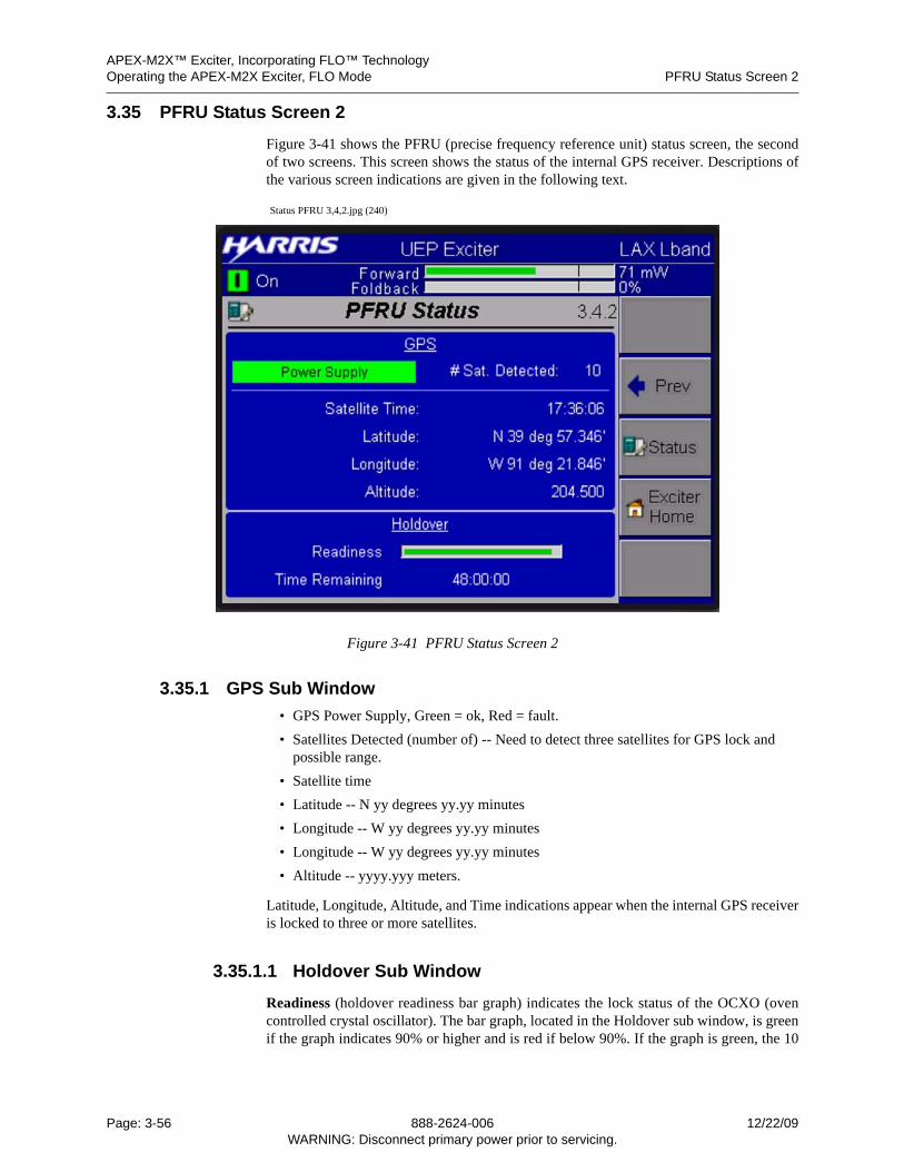
APEX-M2X™ Exciter, Incorporating FLO™ TechnologyOperating the APEX-M2X Exciter, FLO Mode PFRU Status Screen 2
3.35 PFRU Status Screen 2
Figure 3-41 shows the PFRU (precise frequency reference unit) status screen, the secondof two screens. This screen shows the status of the internal GPS receiver. Descriptions ofthe various screen indications are given in the following text.
Status PFRU 3,4,2.jpg (240)
Figure 3-41 PFRU Status Screen 2
3.35.1 GPS Sub Window
• GPS Power Supply, Green = ok, Red = fault.
• Satellites Detected (number of) -- Need to detect three satellites for GPS lock and possible range.
• Satellite time
• Latitude -- N yy degrees yy.yy minutes
• Longitude -- W yy degrees yy.yy minutes
• Longitude -- W yy degrees yy.yy minutes
• Altitude -- yyyy.yyy meters.
Latitude, Longitude, Altitude, and Time indications appear when the internal GPS receiveris locked to three or more satellites.
3.35.1.1 Holdover Sub Window
Readiness (holdover readiness bar graph) indicates the lock status of the OCXO (ovencontrolled crystal oscillator). The bar graph, located in the Holdover sub window, is greenif the graph indicates 90% or higher and is red if below 90%. If the graph is green, the 10
Page: 3-56 888-2624-006 12/22/09WARNING: Disconnect primary power prior to servicing.
APEX-M2X™ Exciter, Incorporating FLO™ TechnologyPFRU Status Screen 2 Operating the APEX-M2X Exciter, FLO Mode
2624
6s3
00
New
Scr
een
s.fm
MHz OCXO PLL is locked to the 1PPS reference and is capable of holdover (free running)for 24 hours. This means that the oscillator frequency will remain within tolerance andallow transmitter operation for 24 hours without being synchronized to its reference.
Time Remaining. When the 1PPS reference is lost, the OCXO Holdover Readiness graphturns white and the 10 MHz OCXO is free running. The Holdover Time Remaining indi-cation, located in the Holdover sub window, starts to count down from 24 hours. When itstime reaches zero, the exciter will mute, if it is in the SFN mode.
When the reference is restored and the oscillator starts to lock, the OCXO HoldoverReadiness graph indication will start to increase. While it is below 90%, and the graph isred, the exciter, if in the SFN mode, will be muted. When the graph reaches 90% or higher,it will turn green and the exciter, if in the SFN mode, will unmute.
Additional information is given below.
• OCXO Holdover Readiness graph percentage represents the difference between the maximum and minimum oscillator control value over a 20 minute window, and is the indication of how well disciplined the oscillator is. If the holdover status value is above 90%, then the oscillator is only changing +/- 0.0003 Hz, and is good enough to use. The value will never reach 100%, but when well disciplined should be 90% or greater.
• The 10MHz OCXO is divided down to a 1Hz frequency and locked, via a phase locked loop, to a GPS 1PPS (pulse per second) reference signal. The purpose is to cre-ate a synthesized 1PPS signal which is used as a timing signal, for example, to syn-chronize a single frequency network. The 10 MHz OCXO signal is also used as a reference for the local oscillator, which determines the RF output frequency of the ex-citer.
• The synthesized 1PPS signal will be present even when the GPS 1PPS reference is missing. In that case, the 10 MHz OCXO holdover oscillator will be free running.
Holdover Time Remaining indicates the amount of time, in hours, minutes, and sec-onds, that the free running 10 MHz OCXO will remain within its frequency tolerance and the exciter will remain unmuted.
12/22/09 888-2624-006 Page: 3-57WARNING: Disconnect primary power prior to servicing.
APEX-M2X™ Exciter, Incorporating FLO™ TechnologyOperating the APEX-M2X Exciter, FLO Mode Battery Backup Status Screen
3.36 Battery Backup Status Screen
Figure 3-42 shows the battery backup status screen. This screen gives the statuses and oneanalog value for the battery backup board of the exciter. Descriptions of the various batterybackup screen indications are given in the following text.
Status Battery Backup 3,1.jpg (240)
Figure 3-42 Battery Backup Status Screen
3.36.1 Status Sub Window
Present, Green = battery backup present, Grey = absent.
(Battery) Pack Fault, Grey = OK, Red = fault. 4.8 volt battery supplies battery backupcircuit. Battery faults when its voltage drops to 4.2 volts (87.5% of its nominal voltage).
UPS Status Control (Battery), Blue when battery backup disabled, When battery backup isenables, Green = ok and Red = fault.
Battery Charging, Green = battery is charging, blue = battery not charging or battery notsufficiently charged. Cory to provide.
Battery Backup Disable, This is an input from the transmitter I/O. It is used to disable thebackup battery. The input for this control is pin 9 of the UHF Transmitter InterfaceConnector, which is found on the transmitter I/O board option.
+12VDC Battery readout. A fault occur if the 12 volt output drops to 10 volts. The 4.8 voltoutput of the backup battery is inverted up to 12 VDC.
Page: 3-58 888-2624-006 12/22/09WARNING: Disconnect primary power prior to servicing.
APEX-M2X™ Exciter, Incorporating FLO™ TechnologyRevisions Screen 1 Operating the APEX-M2X Exciter, FLO Mode
2624
6s3
00
New
Scr
een
s.fm
3.37 Revisions Screen 1
Figure 3-43 shows the revisions screen 1. This screen gives the software revision levels forthe various sections of digital circuitry within the exciter.
Status Revisions 3,6,1.jpg (240)
Figure 3-43 Revisions Screen 1
12/22/09 888-2624-006 Page: 3-59WARNING: Disconnect primary power prior to servicing.
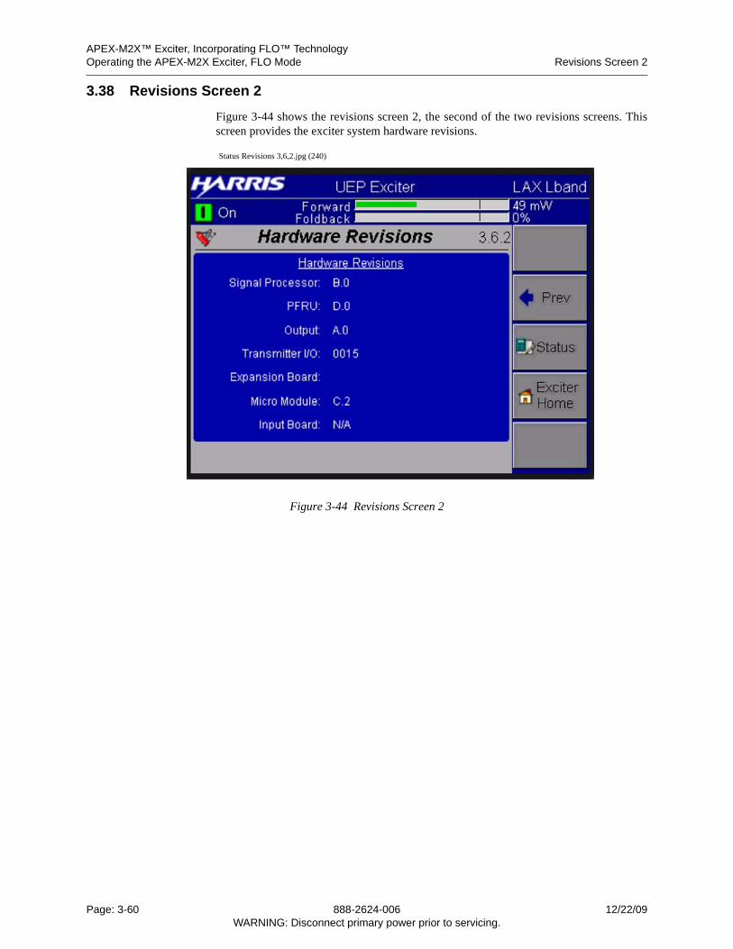
APEX-M2X™ Exciter, Incorporating FLO™ TechnologyOperating the APEX-M2X Exciter, FLO Mode Revisions Screen 2
3.38 Revisions Screen 2
Figure 3-44 shows the revisions screen 2, the second of the two revisions screens. Thisscreen provides the exciter system hardware revisions.
Status Revisions 3,6,2.jpg (240)
Figure 3-44 Revisions Screen 2
Page: 3-60 888-2624-006 12/22/09WARNING: Disconnect primary power prior to servicing.
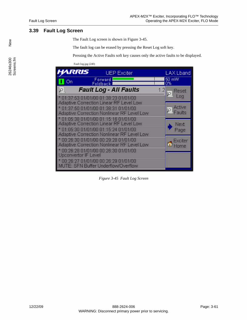
APEX-M2X™ Exciter, Incorporating FLO™ TechnologyFault Log Screen Operating the APEX-M2X Exciter, FLO Mode
2624
6s3
00
New
Scr
een
s.fm
3.39 Fault Log Screen
The Fault Log screen is shown in Figure 3-45.
The fault log can be erased by pressing the Reset Log soft key.
Pressing the Active Faults soft key causes only the active faults to be displayed.
Fault log.jpg (240)
Figure 3-45 Fault Log Screen
12/22/09 888-2624-006 Page: 3-61WARNING: Disconnect primary power prior to servicing.
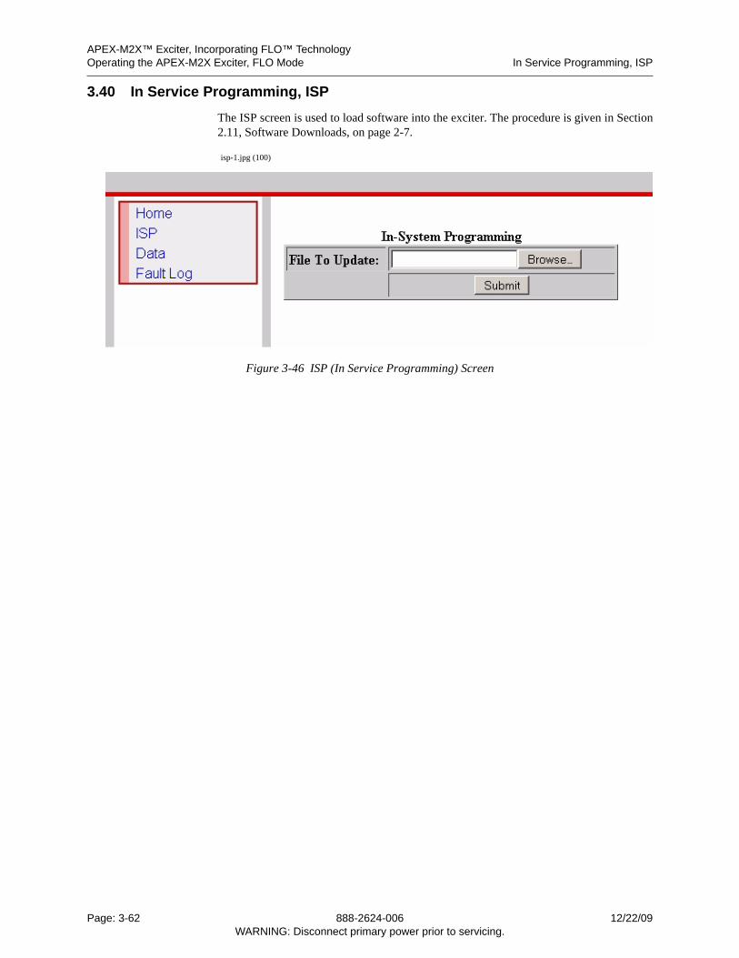
APEX-M2X™ Exciter, Incorporating FLO™ TechnologyOperating the APEX-M2X Exciter, FLO Mode In Service Programming, ISP
3.40 In Service Programming, ISP
The ISP screen is used to load software into the exciter. The procedure is given in Section2.11, Software Downloads, on page 2-7.
isp-1.jpg (100)
Figure 3-46 ISP (In Service Programming) Screen
Page: 3-62 888-2624-006 12/22/09WARNING: Disconnect primary power prior to servicing.
APEX-M2X™ ExciterGeneral Description APEX-M2X™ Exciter Theory of Operation
2624
1s4
00.fm
4 APEX-M2X™ Exciter Theory of Operation
4.1 General Description
A top view of the APEX-M2X exciter with the cover removed is shown in Figure 4-1.
This exciter can operate in the digital or analog mode. To operate in the analog mode, theAnalog Input Board (AIB) is required. The analog input board provides the input connec-tors for the analog TV video and audio inputs.
The digital program input to the exciter is a data signal called the “Transport Stream”which can be coded in ASI (signal input 1 and LP 1) or SMPTE (signal input 2 and LP 2).These inputs have an impedance of 75 ohms. This form of coding allows the clock signalto be recovered from the data stream, instead of requiring separate clock and data paths.
The exciter processes its inputs into analog or digital on-channel transmission signalsneeded as drive for the transmitter power amplifiers. RTAC™ (Real Time AdaptiveCorrection) correction circuits in the exciter predistort the exciter’s digital RF output tocompensate for errors which occur in the power amplifiers and the high level RF outputmask filter. The purpose of the correction circuits is to produce a transmitter output signalwith good EVM (error vector magnitude) or MER (modulation error rate), good digitalsignal to noise ratio and very low intermodulation (adjacent channel) products. RTAC™processing, used in digital operating modes only, in the signal processing board continuallymonitors and trims exciter linear and nonlinear correction to maintain top performance.
Control and monitoring of the exciter is provided through an external computer which islinked to the exciter through an ethernet connection, refer to Chapter 2, Connecting To TheAPEX-M2X Exciter. In some transmitters exciter control is also extended to the trans-mitter control cabinet GUI (graphical user interface) display.
The APEX-M2X exciter performs the following general functions:
• ASI (signal 1 and LP 1) or SMPTE (signal 2 and LP 2) Input & Clock Distribution
• Data synchronization
• Channel encoding
• Pre-correction
• Nyquist filtering (spectral shaping)
• Up conversion
• RTAC™ (Real Time Adaptive Correction)
The on-channel RF signal is output through a 50-ohm SMA connector at the rear of theexciter. This output signal is suitable for amplification in subsequent high-power stages.
12/22/09 888-2624-001 Page: 4-1WARNING: Disconnect primary power prior to servicing.
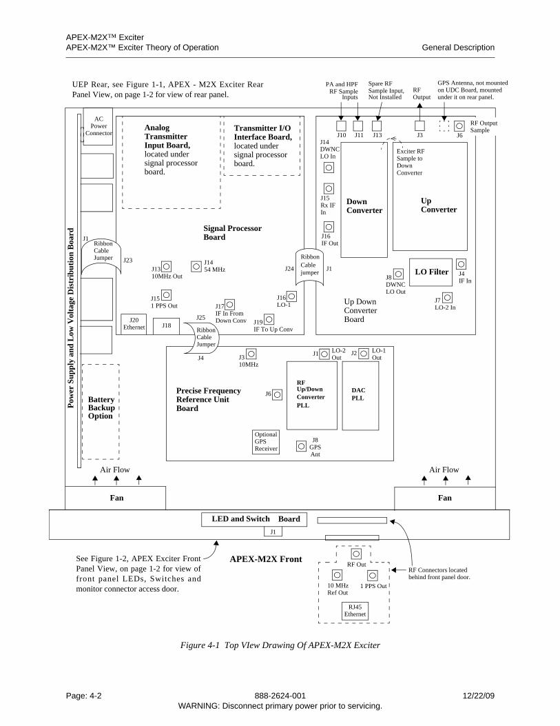
APEX-M2X™ ExciterAPEX-M2X™ Exciter Theory of Operation General Description
d
Figure 4-1 Top VIew Drawing Of APEX-M2X Exciter
Signal ProcessorBoard
AnalogTransmitterInput Board,located undersignal processorboard.
Transmitter I/OInterface Board,located undersignal processorboard.
Up DownConverter Board
FanFan
Air FlowAir Flow
Precise FrequencyReference UnitBoard
RibbonCablejumper
RibbonCableJumper
RibbonCableJumper
BatteryBackupOption
ACPower
Pow
er S
up
ply
an
d L
ow V
olta
ge D
istr
ibu
tion
Boa
rd
UpConverter
DownConverter
LO Filter
PA and HPFRFOutputInputs
Exciter RFSample toDownConverter
Spare RFSample Input,RF Sample
RFDACPLL
Up/DownConverterPLL
OptionalGPSReceiver
J3J1 J2
J8GPSAnt
J6
J1
J23J24 J1
J25
J4
GPS Antenna, not mounte
LO-2 LO-1
J1454 MHzJ13
10MHz Out
J151 PPS Out
10MHz
J8DWNCLO Out
J14DWNCLO In
J15Rx IFIn
J7LO-2 In
J4IF In
J16IF Out
J16LO-1
J19IF To Up Conv
J17IF In From
Connector
Down Conv
OutOut
Not Installed
J10 J11 J13 J3 J6
on UDC Board, mounted
RF OutputSample
under it on rear panel.
J20Ethernet J18
APEX-M2X Front
LED and Switch
RF Connectors locatedRF Out
10 MHz 1 PPS OutRef Out
behind front panel door.
RJ45Ethernet
J1
Board
See Figure 1-2, APEX Exciter FrontPanel View, on page 1-2 for view offront panel LEDs, Switches andmonitor connector access door.
UEP Rear, see Figure 1-1, APEX - M2X Exciter RearPanel View, on page 1-2 for view of rear panel.
Page: 4-2 888-2624-001 12/22/09WARNING: Disconnect primary power prior to servicing.
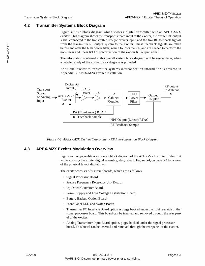
APEX-M2X™ ExciterTransmitter Systems Block Diagram APEX-M2X™ Exciter Theory of Operation
2624
1s4
00.fm
4.2 Transmitter Systems Block Diagram
Figure 4-2 is a block diagram which shows a digital transmitter with an APEX-M2Xexciter. This diagram shows the transport stream input to the exciter, the exciter RF outputsignal connected to the transmitter IPA (or driver) input, and the two RF feedback signalsfrom the transmitter RF output system to the exciter. These feedback signals are takenbefore and after the high power filter, which follows the PA, and are needed to perform thenon-linear and linear RTAC precorrection of the exciter RF output signal.
The information contained in this overall system block diagram will be needed later, whena detailed study of the exciter block diagram is provided.
Additional exciter to transmitter systems interconnection information is covered inAppendix B, APEX-M2X Exciter Installation.
Figure 4-2 APEX -M2X Exciter/ Transmitter - RF Interconnection Block Diagram
4.3 APEX-M2X Exciter Modulation Overview
Figure 4-3, on page 4-6 is an overall block diagram of the APEX-M2X exciter. Refer to itwhile studying the exciter digital assembly, also, refer to Figure 5-4, on page 5-3 for a viewof the physical layout digital tray.
The exciter consists of 9 circuit boards, which are as follows.
• Signal Processor Board.
• Precise Frequency Reference Unit Board.
• Up Down Converter Board.
• Power Supply and Low Voltage Distribution Board.
• Battery Backup Option Board.
• Front Panel LED and Switch Board.
• Transmitter I/O Interface Board option is piggy backed under the right rear side of the signal processor board. This board can be inserted and removed through the rear pan-el of the exciter.
• Analog Transmitter Input Board option, piggy backed under the signal processor board. This board can be inserted and removed through the rear panel of the exciter.
PAIPA or
OutputCoupler
HighPower
PACabinet
FilterCoupler
APEX-M2XExciter
RF output to Antenna
PA (Non-Linear) RTAC
RF Feedback SampleHPF Output (Linear) RTAC
RF Feedback Sample
TransportStreamor Analog
Exciter RFOutput
Driver
Input
12/22/09 888-2624-001 Page: 4-3WARNING: Disconnect primary power prior to servicing.
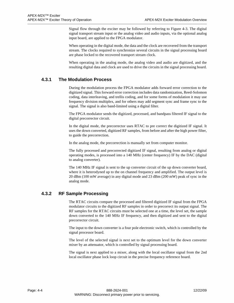
APEX-M2X™ ExciterAPEX-M2X™ Exciter Theory of Operation APEX-M2X Exciter Modulation Overview
Signal flow through the exciter may be followed by referring to Figure 4-3. The digitalsignal transport stream input or the analog video and audio inputs, via the optional analoginput board, are applied to the FPGA modulator.
When operating in the digital mode, the data and the clock are recovered from the transportstream. The clocks required to synchronize several circuits in the signal processing boardare phase locked to the recovered transport stream clock.
When operating in the analog mode, the analog video and audio are digitized, and theresulting digital data and clock are used to drive the circuits in the signal processing board.
4.3.1 The Modulation Process
During the modulation process the FPGA modulator adds forward error correction to thedigitized signal. This forward error correction includes data randomization, Reed-Solomoncoding, data interleaving, and trellis coding, and for some forms of modulation it may usefrequency division multiplex, and for others may add segment sync and frame sync to thesignal. The signal is also band-limited using a digital filter.
The FPGA modulator sends the digitized, processed, and bandpass filtered IF signal to thedigital precorrector circuit.
In the digital mode, the precorrector uses RTAC to pre correct the digitized IF signal. Ituses the down converted, digitized RF samples, from before and after the high power filter,to guide the precorrection.
In the analog mode, the precorrection is manually set from computer monitor.
The fully processed and precorrected digitized IF signal, resulting from analog or digitaloperating modes, is processed into a 140 MHz (center frequency) IF by the DAC (digitalto analog converter).
The 140 MHz IF signal is sent to the up converter circuit of the up down converter board,where it is heterodyned up to the on channel frequency and amplified. The output level is20 dBm (100 mW average) in any digital mode and 23 dBm (200 mW) peak of sync in theanalog mode.
4.3.2 RF Sample Processing
The RTAC circuits compare the processed and filtered digitized IF signal from the FPGAmodulator circuits to the digitized RF samples in order to precorrect its output signal. TheRF samples for the RTAC circuits must be selected one at a time, the level set, the sampledown converted to the 140 MHz IF frequency, and then digitized and sent to the digitalprecorrector circuit.
The input to the down converter is a four pole electronic switch, which is controlled by thesignal processor board.
The level of the selected signal is next set to the optimum level for the down convertermixer by an attenuator, which is controlled by signal processing board.
The signal is next applied to a mixer, along with the local oscillator signal from the 2ndlocal oscillator phase lock loop circuit in the precise frequency reference board.
Page: 4-4 888-2624-001 12/22/09WARNING: Disconnect primary power prior to servicing.

APEX-M2X™ ExciterAPEX-M2X Exciter Modulation Overview APEX-M2X™ Exciter Theory of Operation
2624
1s4
00.fm
The resultant 140 MHz signal is then filtered, to remove mixing products, and sent to anattenuator, controlled from the signal processor board, where its level is set to optimum forits next destination, the ADC (analog to digital converter) in the signal processor board.
In the ADC, the IF signal is digitized and sent to the digital precorrector (RTAC) circuit.
The RTAC circuits in the digital precorrector performs both linear (response and groupdelay) and non-linear (phase and linearity) pre-correction on the signal.
12/22/09 888-2624-001 Page: 4-5WARNING: Disconnect primary power prior to servicing.
APEX-M2X™ ExciterAPEX-M2X™ Exciter Theory of Operation APEX-M2X Exciter Modulation Overview
Figure 4-3 APEX Exciter - Signal Flow Block Diagram
RF OutputAmplifier
Up Converter
MultipleInputDown ConverterRF Switch
Down Converter
1stL.O.
2ndL.O.
10 MHzReference
Exciter Sample Input
Spare Input
PA Sample Input
HPF Sample Input
Exciter RFOutput
DAC
ADC
DigitalPrecorrector
FPGA
Transport ASI HP A
54 MHzClock
Part of FPGA
AnalogLoopback
and
Local OscDistribution
Local OscDACClockFrequency
Up Down Converter Board
Precise FrequencyReference Board
Control
GPSReceiver
ASI LP ASMPTE HP BSMPTE LP B
StreamSwitch
Optional AnalogInput Board
Video
Video AuxBP Sync
Audio 1 (L + R)
Audio 2 (L + R)
Comp. Audio
Modulator
Modulator
1PPS
10 M
Hz
Tun
e1
PPS
Int 1
0 M
Hz
Con
trol
Signal Processing Board
GPSAntenna
J15140 MHz IF Input
DivideBy 4
140 MHz IF Signal
Page: 4-6 888-2624-001 12/22/09WARNING: Disconnect primary power prior to servicing.
APEX-M2X™ ExciterLow Voltage Power Supply Board APEX-M2X™ Exciter Theory of Operation
2624
1s4
00.fm
4.4 Low Voltage Power Supply Board
The low voltage power supply for the APEX-M2X exciter is mounted to the left inside wall of the exciter chassis, as shown in Figure 4-1, on page 4-2. The following items are mounted on the power supply board.
• The AC Input connector.
• A +5V, +24V, and -12V switching power supply, mounted towards the rear of the power supply board.
• A +12V switching power supply, mounted in the center of the power supply board.
• Provision for an optional battery backup board, mounted at the front of the power supply board.
Power Supplies outputs to exciter is via a ribbon cable to the signal processor board. Power to the other boards is supplied via the signal processing board.
The block diagram of the low voltage power supply system is shown in Figure 4-4.
4.4.1 AC Input
The APEX-M2X exciter has a filtered IEC 320/C14 AC input connector. The LVPS Distri-bution board accepts AC voltages in the range of 100 - 240 Vac at 50-60 Hz. The inputs are fused at 4A 250V slow blow fuse. The maximum power for the exciter is 180 W.
4.4.2 LVPS
The AC input for each of the two low voltage power supplies listed below is 100 - 240 Vac at 50-60 Hz.
The ECM100UT32 power supply is capable of delivering +5.0V at 10A, +24.0V at 2A, and -12.0V at 0.8A.
The ECM60US12 power supply is capable of delivering +12.0V at 5A.
Both power supplies are mounted directly to the LVPS Distribution board by snap-topPEM standoffs.
4.4.3 Fans
The LVPS board will have provisions for two +12Vdc fans. The fans will be fused with a PTC at 1.35A and the dc input will be filtered.
12/22/09 888-2624-001 Page: 4-7WARNING: Disconnect primary power prior to servicing.
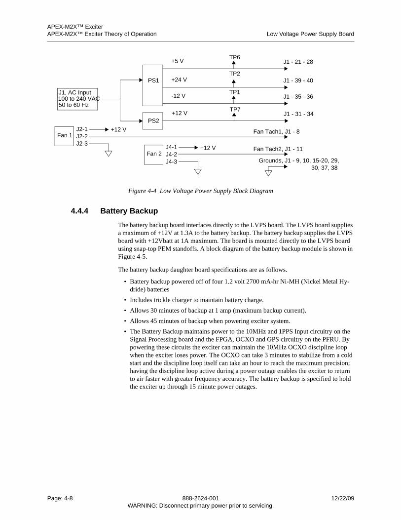
APEX-M2X™ ExciterAPEX-M2X™ Exciter Theory of Operation Low Voltage Power Supply Board
Figure 4-4 Low Voltage Power Supply Block Diagram
4.4.4 Battery Backup
The battery backup board interfaces directly to the LVPS board. The LVPS board supplies a maximum of +12V at 1.3A to the battery backup. The battery backup supplies the LVPS board with +12Vbatt at 1A maximum. The board is mounted directly to the LVPS board using snap-top PEM standoffs. A block diagram of the battery backup module is shown in Figure 4-5.
The battery backup daughter board specifications are as follows.
• Battery backup powered off of four 1.2 volt 2700 mA-hr Ni-MH (Nickel Metal Hy-dride) batteries
• Includes trickle charger to maintain battery charge.
• Allows 30 minutes of backup at 1 amp (maximum backup current).
• Allows 45 minutes of backup when powering exciter system.
• The Battery Backup maintains power to the 10MHz and 1PPS Input circuitry on the Signal Processing board and the FPGA, OCXO and GPS circuitry on the PFRU. By powering these circuits the exciter can maintain the 10MHz OCXO discipline loop when the exciter loses power. The OCXO can take 3 minutes to stabilize from a cold start and the discipline loop itself can take an hour to reach the maximum precision; having the discipline loop active during a power outage enables the exciter to return to air faster with greater frequency accuracy. The battery backup is specified to hold the exciter up through 15 minute power outages.
J1, AC Input100 to 240 VAC50 to 60 Hz
+12 V
PS1
PS2
TP7J1 - 31 - 34
+5 VTP6
J1 - 21 - 28
+24 VTP2
J1 - 39 - 40
-12 VTP1
J1 - 35 - 36
J2-1J2-2J2-3
J4-1J4-2J4-3
Fan 1
Fan 2
+12 V
+12 V
Fan Tach1, J1 - 8
Fan Tach2, J1 - 11
Grounds, J1 - 9, 10, 15-20, 29,30, 37, 38
Page: 4-8 888-2624-001 12/22/09WARNING: Disconnect primary power prior to servicing.
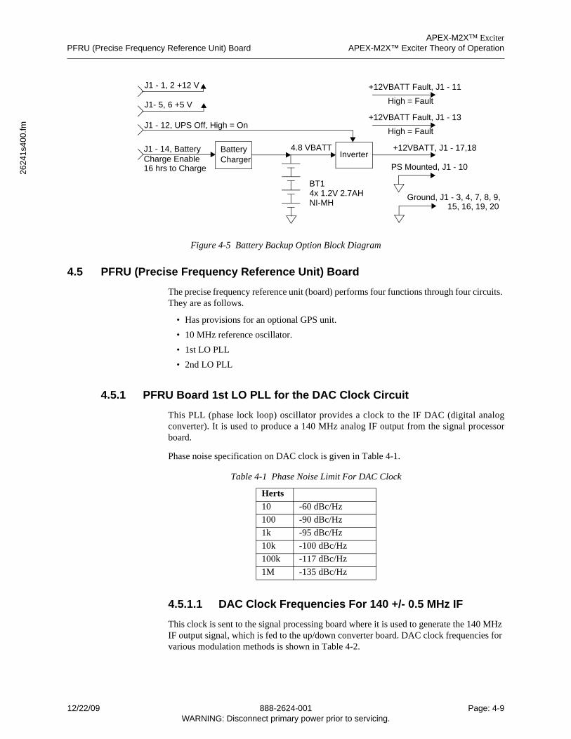
APEX-M2X™ ExciterPFRU (Precise Frequency Reference Unit) Board APEX-M2X™ Exciter Theory of Operation
2624
1s4
00.fm
Figure 4-5 Battery Backup Option Block Diagram
4.5 PFRU (Precise Frequency Reference Unit) Board
The precise frequency reference unit (board) performs four functions through four circuits. They are as follows.
• Has provisions for an optional GPS unit.
• 10 MHz reference oscillator.
• 1st LO PLL
• 2nd LO PLL
4.5.1 PFRU Board 1st LO PLL for the DAC Clock Circuit
This PLL (phase lock loop) oscillator provides a clock to the IF DAC (digital analogconverter). It is used to produce a 140 MHz analog IF output from the signal processorboard.
Phase noise specification on DAC clock is given in Table 4-1.
4.5.1.1 DAC Clock Frequencies For 140 +/- 0.5 MHz IF
This clock is sent to the signal processing board where it is used to generate the 140 MHz IF output signal, which is fed to the up/down converter board. DAC clock frequencies for various modulation methods is shown in Table 4-2.
Table 4-1 Phase Noise Limit For DAC Clock
Herts
10 -60 dBc/Hz
100 -90 dBc/Hz
1k -95 dBc/Hz
10k -100 dBc/Hz
100k -117 dBc/Hz
1M -135 dBc/Hz
BatteryCharger
Inverter
BT14x 1.2V 2.7AHNI-MH
+12VBATT, J1 - 17,18
+12VBATT Fault, J1 - 13
High = Fault
+12VBATT Fault, J1 - 11
High = Fault
Ground, J1 - 3, 4, 7, 8, 9,15, 16, 19, 20
PS Mounted, J1 - 10
J1 - 1, 2 +12 V
J1- 5, 6 +5 V
J1 - 12, UPS Off, High = On
J1 - 14, BatteryCharge Enable16 hrs to Charge
4.8 VBATT
12/22/09 888-2624-001 Page: 4-9WARNING: Disconnect primary power prior to servicing.
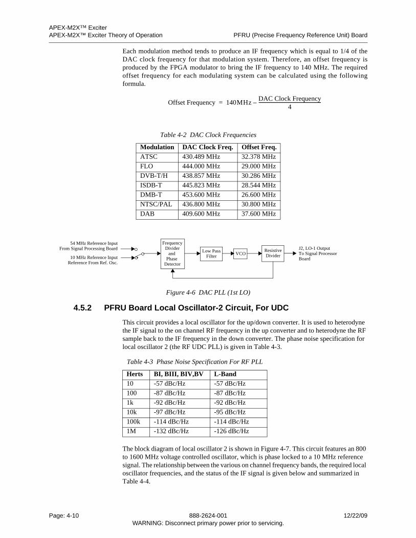
APEX-M2X™ ExciterAPEX-M2X™ Exciter Theory of Operation PFRU (Precise Frequency Reference Unit) Board
Each modulation method tends to produce an IF frequency which is equal to 1/4 of theDAC clock frequency for that modulation system. Therefore, an offset frequency isproduced by the FPGA modulator to bring the IF frequency to 140 MHz. The requiredoffset frequency for each modulating system can be calculated using the followingformula.
Figure 4-6 DAC PLL (1st LO)
4.5.2 PFRU Board Local Oscillator-2 Circuit, For UDC
This circuit provides a local oscillator for the up/down converter. It is used to heterodyne the IF signal to the on channel RF frequency in the up converter and to heterodyne the RF sample back to the IF frequency in the down converter. The phase noise specification for local oscillator 2 (the RF UDC PLL) is given in Table 4-3.
The block diagram of local oscillator 2 is shown in Figure 4-7. This circuit features an 800 to 1600 MHz voltage controlled oscillator, which is phase locked to a 10 MHz reference signal. The relationship between the various on channel frequency bands, the required local oscillator frequencies, and the status of the IF signal is given below and summarized in Table 4-4.
Table 4-2 DAC Clock Frequencies
Modulation DAC Clock Freq. Offset Freq.
ATSC 430.489 MHz 32.378 MHz
FLO 444.000 MHz 29.000 MHz
DVB-T/H 438.857 MHz 30.286 MHz
ISDB-T 445.823 MHz 28.544 MHz
DMB-T 453.600 MHz 26.600 MHz
NTSC/PAL 436.800 MHz 30.800 MHz
DAB 409.600 MHz 37.600 MHz
Table 4-3 Phase Noise Specification For RF PLL
Herts BI, BIII, BIV,BV L-Band
10 -57 dBc/Hz -57 dBc/Hz
100 -87 dBc/Hz -87 dBc/Hz
1k -92 dBc/Hz -92 dBc/Hz
10k -97 dBc/Hz -95 dBc/Hz
100k -114 dBc/Hz -114 dBc/Hz
1M -132 dBc/Hz -126 dBc/Hz
Offset Frequency 140MHzDAC Clock Frequency
4-------------------------------------------------------–=
FrequencyDivider
and Phase
Detector
Low PassFilter VCO
ResistiveDivider
J2, LO-1 OutputTo Signal ProcessorBoard10 MHz Reference Input
Reference From Ref. Osc.
54 MHz Reference InputFrom Signal Processing Board
Page: 4-10 888-2624-001 12/22/09WARNING: Disconnect primary power prior to servicing.
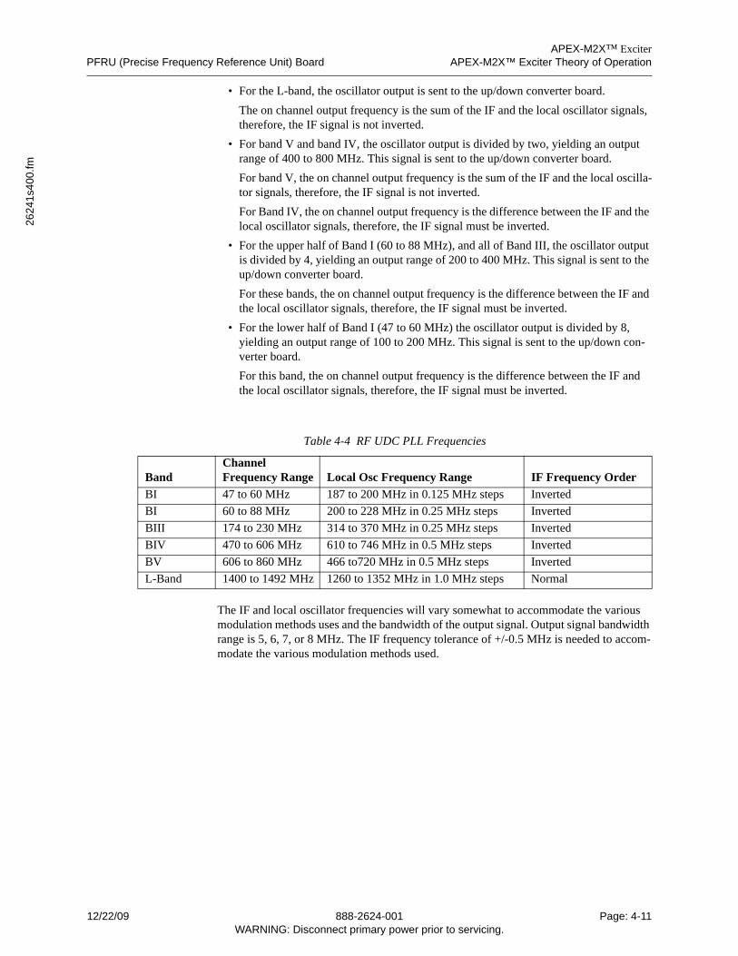
APEX-M2X™ ExciterPFRU (Precise Frequency Reference Unit) Board APEX-M2X™ Exciter Theory of Operation
2624
1s4
00.fm
• For the L-band, the oscillator output is sent to the up/down converter board.
The on channel output frequency is the sum of the IF and the local oscillator signals, therefore, the IF signal is not inverted.
• For band V and band IV, the oscillator output is divided by two, yielding an output range of 400 to 800 MHz. This signal is sent to the up/down converter board.
For band V, the on channel output frequency is the sum of the IF and the local oscilla-tor signals, therefore, the IF signal is not inverted.
For Band IV, the on channel output frequency is the difference between the IF and the local oscillator signals, therefore, the IF signal must be inverted.
• For the upper half of Band I (60 to 88 MHz), and all of Band III, the oscillator output is divided by 4, yielding an output range of 200 to 400 MHz. This signal is sent to the up/down converter board.
For these bands, the on channel output frequency is the difference between the IF and the local oscillator signals, therefore, the IF signal must be inverted.
• For the lower half of Band I (47 to 60 MHz) the oscillator output is divided by 8, yielding an output range of 100 to 200 MHz. This signal is sent to the up/down con-verter board.
For this band, the on channel output frequency is the difference between the IF and the local oscillator signals, therefore, the IF signal must be inverted.
The IF and local oscillator frequencies will vary somewhat to accommodate the various modulation methods uses and the bandwidth of the output signal. Output signal bandwidth range is 5, 6, 7, or 8 MHz. The IF frequency tolerance of +/-0.5 MHz is needed to accom-modate the various modulation methods used.
Table 4-4 RF UDC PLL Frequencies
BandChannel Frequency Range Local Osc Frequency Range IF Frequency Order
BI 47 to 60 MHz 187 to 200 MHz in 0.125 MHz steps Inverted
BI 60 to 88 MHz 200 to 228 MHz in 0.25 MHz steps Inverted
BIII 174 to 230 MHz 314 to 370 MHz in 0.25 MHz steps Inverted
BIV 470 to 606 MHz 610 to 746 MHz in 0.5 MHz steps Inverted
BV 606 to 860 MHz 466 to720 MHz in 0.5 MHz steps Inverted
L-Band 1400 to 1492 MHz 1260 to 1352 MHz in 1.0 MHz steps Normal
12/22/09 888-2624-001 Page: 4-11WARNING: Disconnect primary power prior to servicing.
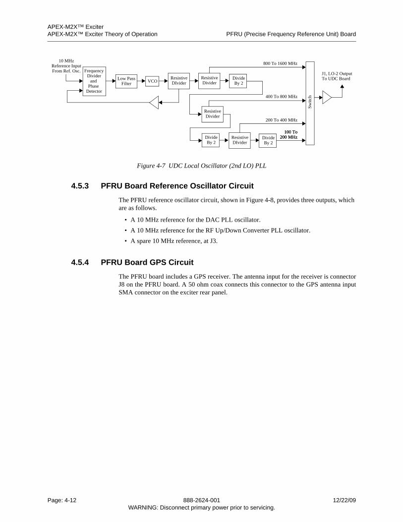
APEX-M2X™ ExciterAPEX-M2X™ Exciter Theory of Operation PFRU (Precise Frequency Reference Unit) Board
Figure 4-7 UDC Local Oscillator (2nd LO) PLL
4.5.3 PFRU Board Reference Oscillator Circuit
The PFRU reference oscillator circuit, shown in Figure 4-8, provides three outputs, which are as follows.
• A 10 MHz reference for the DAC PLL oscillator.
• A 10 MHz reference for the RF Up/Down Converter PLL oscillator.
• A spare 10 MHz reference, at J3.
4.5.4 PFRU Board GPS Circuit
The PFRU board includes a GPS receiver. The antenna input for the receiver is connectorJ8 on the PFRU board. A 50 ohm coax connects this connector to the GPS antenna inputSMA connector on the exciter rear panel.
FrequencyDivider
and Phase
Detector
Low PassFilter VCO
ResistiveDIvider
J1, LO-2 OutputTo UDC Board
10 MHzReference InputFrom Ref. Osc.
Sw
itch
DivideBy 2
ResistiveDivider
DivideBy 2
ResistiveDivider
DivideBy 2
ResistiveDIvider
800 To 1600 MHz
200 To 400 MHz
400 To 800 MHz
100 To 200 MHz
100 To 200 MHz
Page: 4-12 888-2624-001 12/22/09WARNING: Disconnect primary power prior to servicing.
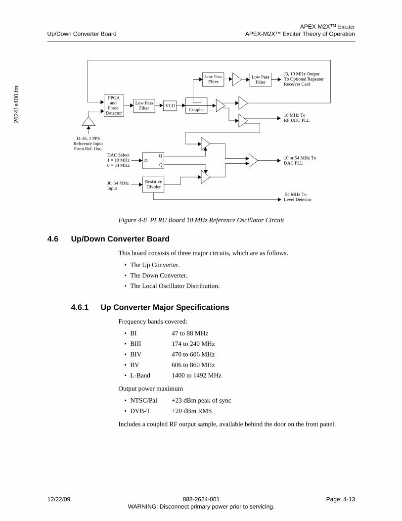
APEX-M2X™ ExciterUp/Down Converter Board APEX-M2X™ Exciter Theory of Operation
2624
1s4
00.fm
Figure 4-8 PFRU Board 10 MHz Reference Oscillator Circuit
4.6 Up/Down Converter Board
This board consists of three major circuits, which are as follows.
• The Up Converter.
• The Down Converter.
• The Local Oscillator Distribution.
4.6.1 Up Converter Major Specifications
Frequency bands covered:
• BI 47 to 88 MHz
• BIII 174 to 240 MHz
• BIV 470 to 606 MHz
• BV 606 to 860 MHz
• L-Band 1400 to 1492 MHz
Output power maximum
• NTSC/Pal +23 dBm peak of sync
• DVB-T +20 dBm RMS
Includes a coupled RF output sample, available behind the door on the front panel.
FPGAand
Phase Detector
Low PassFilter VCO
Coupler
J4-16, 1 PPSReference InputFrom Ref. Osc.
Low PassFilter
J3, 10 MHz OutputTo Optional RepeaterLow Pass
Filter Receiver Card
10 MHz ToRF UDC PLL
10 or 54 MHz ToDAC PLL
QD
Q
ResistiveDIvider
DAC Select1 = 10 MHz0 = 54 MHz
J6, 54 MHz Input
54 MHz ToLevel Detector
12/22/09 888-2624-001 Page: 4-13WARNING: Disconnect primary power prior to servicing.
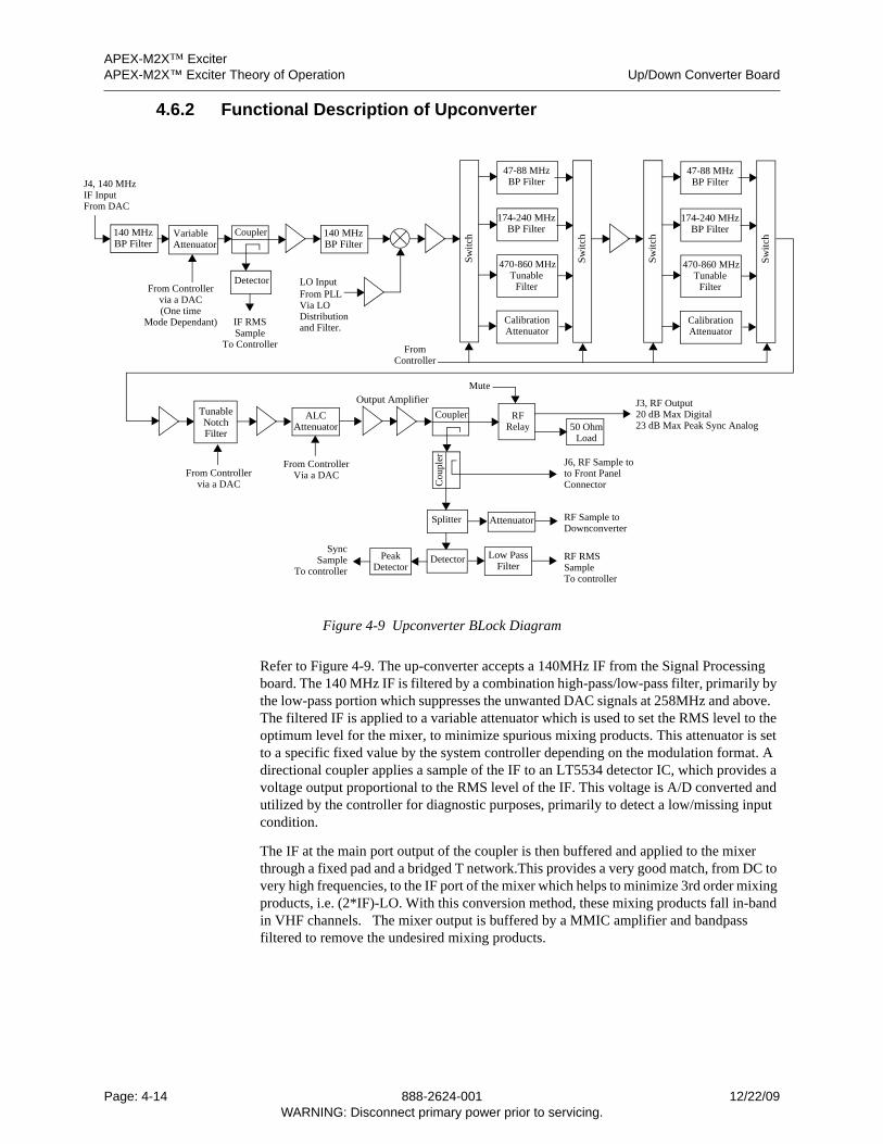
APEX-M2X™ ExciterAPEX-M2X™ Exciter Theory of Operation Up/Down Converter Board
J4IFFr
4.6.2 Functional Description of Upconverter
Figure 4-9 Upconverter BLock Diagram
Refer to Figure 4-9. The up-converter accepts a 140MHz IF from the Signal Processing board. The 140 MHz IF is filtered by a combination high-pass/low-pass filter, primarily by the low-pass portion which suppresses the unwanted DAC signals at 258MHz and above. The filtered IF is applied to a variable attenuator which is used to set the RMS level to the optimum level for the mixer, to minimize spurious mixing products. This attenuator is set to a specific fixed value by the system controller depending on the modulation format. A directional coupler applies a sample of the IF to an LT5534 detector IC, which provides a voltage output proportional to the RMS level of the IF. This voltage is A/D converted and utilized by the controller for diagnostic purposes, primarily to detect a low/missing input condition.
The IF at the main port output of the coupler is then buffered and applied to the mixer through a fixed pad and a bridged T network.This provides a very good match, from DC to very high frequencies, to the IF port of the mixer which helps to minimize 3rd order mixing products, i.e. (2*IF)-LO. With this conversion method, these mixing products fall in-band in VHF channels. The mixer output is buffered by a MMIC amplifier and bandpass filtered to remove the undesired mixing products.
47-88 MHzBP Filter
174-240 MHzBP Filter
470-860 MHzTunable
LO Input Filter
Sw
itch
CalibrationAttenuator
Sw
itch
140 MHzBP Filter
140 MHzBP Filter
VariableAttenuator
Detector
Coupler
IF RMSSample
, 140 MHz Inputom DAC
From Controller
47-88 MHzBP Filter
174-240 MHzBP Filter
470-860 MHzTunable
Filter
Sw
itch
CalibrationAttenuator
Sw
itch
TunableNotch
ALCAttenuator
Output Amplifier
Splitter
SyncSample DetectorPeak
DetectorLow Pass
FilterRF RMSSample
Attenuator RF Sample toDownconverter
RFRelay 50 Ohm
Load
J3, RF Output20 dB Max Digital23 dB Max Peak Sync Analog
FromController
Mute
From Controllervia a DAC
From ControllerVia a DAC
To Controller
To controllerTo controller
From PLLVia LODistributionand Filter.
Coupler
Cou
pler J6, RF Sample to
to Front PanelConnector
Mode Dependant)(One timevia a DAC
Filter
Page: 4-14 888-2624-001 12/22/09WARNING: Disconnect primary power prior to servicing.
APEX-M2X™ ExciterUp/Down Converter Board APEX-M2X™ Exciter Theory of Operation
2624
1s4
00.fm
The two sets of switchable VHF high band and low band bandpass filters, which follow the mixer and buffers, consist of cascaded high-pass/low-pass filters, while UHF is filtered using a tunable bandpass filter. All of the filter banks are appropriately padded so that the gain of any filter path is close to unity. The filtering is performed in two stages of 4-way filter banks.
The first filter bank consists of the following paths:
• Path 1: VHF Low Band LPF
• Path 2: VHF High Band LPF
• Path 3: UHF Tunable BPF
• Path 4: Bypass/Calibration path
The selected filter path is buffered to minimize interaction with the following stage and applied to filter bank two which consists of the following paths:
• Path 1: VHF Low Band HPF
• Path 2: VHF High Band HPF
• Path 3: UHF Tunable BPF
• Path 4: Bypass/Calibration path
This grouping was selected such that an offline calibration routine can automatically tune the UHF bandpass filters independently. By using a fixed ALC voltage and monitoring the output power detector, an algorithm can be implemented to first bypass one filter bank, tune the selected filter for maximum detected power and then find the center of the -1dB points. The process would be repeated with the other filter bank, and then both are switched in. This process could be applied at power-on or anytime a UHF channel change is initiated.
The filtered RF is buffered by a MMIC amplifier. Since the UHF filters are inductively coupled, they exhibit greater high-side attenuation than low-side. A tunable low-side notch filter is included to provide additional suppression of the low-side image (f-280MHz).
The RF is then gain adjusted by a variable attenuator and applied to the output amplifier.The amplifier is followed by a low-loss directional coupler and low-loss RF relay. Thecoupled RF sample is split and one path is routed via embedded stripline to thedown-converter so the adaptive pre-correction can compensate for imperfections of theanalog filters. The other path is applied to an AD8362 demodulating detector IC. Theoutput is applied to two paths. The first is a peak detector which provides peak of sync levelfor analog service. The other path is heavily low-pass filtered to provide average powermeasurement. The RF relay is a SPDT low-loss, high isolation (60dB @ 1.5GHz)microwave relay and is used to place the exciter “offline” for testing purposes. The default,de-energized state switches the exciter output into an on-board 50-Ohm resistive termina-tion. This allows the RF output of the exciter to be muted while still keeping the signalchain active so internal tuning, diagnostics and correction can occur. When un-muted bythe system controller, the RF relay switches the output to a right angle SMA bulkheadconnector on the exciter rear panel.
12/22/09 888-2624-001 Page: 4-15WARNING: Disconnect primary power prior to servicing.
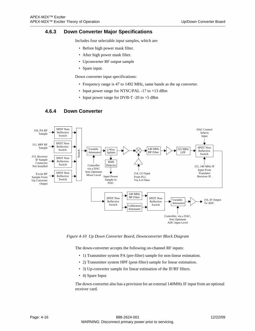
APEX-M2X™ ExciterAPEX-M2X™ Exciter Theory of Operation Up/Down Converter Board
4.6.3 Down Converter Major Specifications
Includes four selectable input samples, which are:
• Before high power mask filter.
• After high power mask filter.
• Upconverter RF output sample
• Spare input.
Down converter input specifications:
• Frequency range is 47 to 1492 MHz, same bands as the up converter.
• Input power range for NTSC/PAL -17 to +13 dBm
• Input power range for DVB-T -20 to +5 dBm
4.6.4 Down Converter
Figure 4-10 Up Down Converter Board, Downconverter Block Diagram
The down-converter accepts the following on-channel RF inputs:
• 1) Transmitter system PA (pre-filter) sample for non-linear estimation.
• 2) Transmitter system HPF (post-filter) sample for linear estimation.
• 3) Up-converter sample for linear estimation of the IF/RF filters.
• 4) Spare Input
The down-converter also has a provision for an external 140MHz IF input from an optional receiver card.
SPDT Non-Reflective
Switch
Sw
itch
SPDT Non-Reflective
Switch
SPDT Non-Reflective
Switch
SPDT Non-Reflective
Switch
VariableAttenuator
Controllervia a DAC
RMS
2-WaySplitter
Detector
Input PowerSample to
DAC
225 MHzLPF
J14, LO InputFrom PLLVia LO Filter
140 MHzBP Filter
J10, PA RFSample
J11, HPF RFSample
Excite RFSample From
J13, ReceiverIF Sample
SPDT Non-Reflective
Switch
SPDT Non-Reflective
Switch
SPDT Non-Reflective
Switch
CalibrationAttenuator
140 MHzBP Filter
VariableAttenuator
Controller, via a DAC,Sets Optimum
ADC Input Level
J16, IF Output To ADC
J15, 140 MHz IFInput FromTranslator
DAC ControlSelectsInput
Receiver IF.
ConnectorNot Installed
Up ConverterOutput
Mixer LevelSets Optimum
Page: 4-16 888-2624-001 12/22/09WARNING: Disconnect primary power prior to servicing.
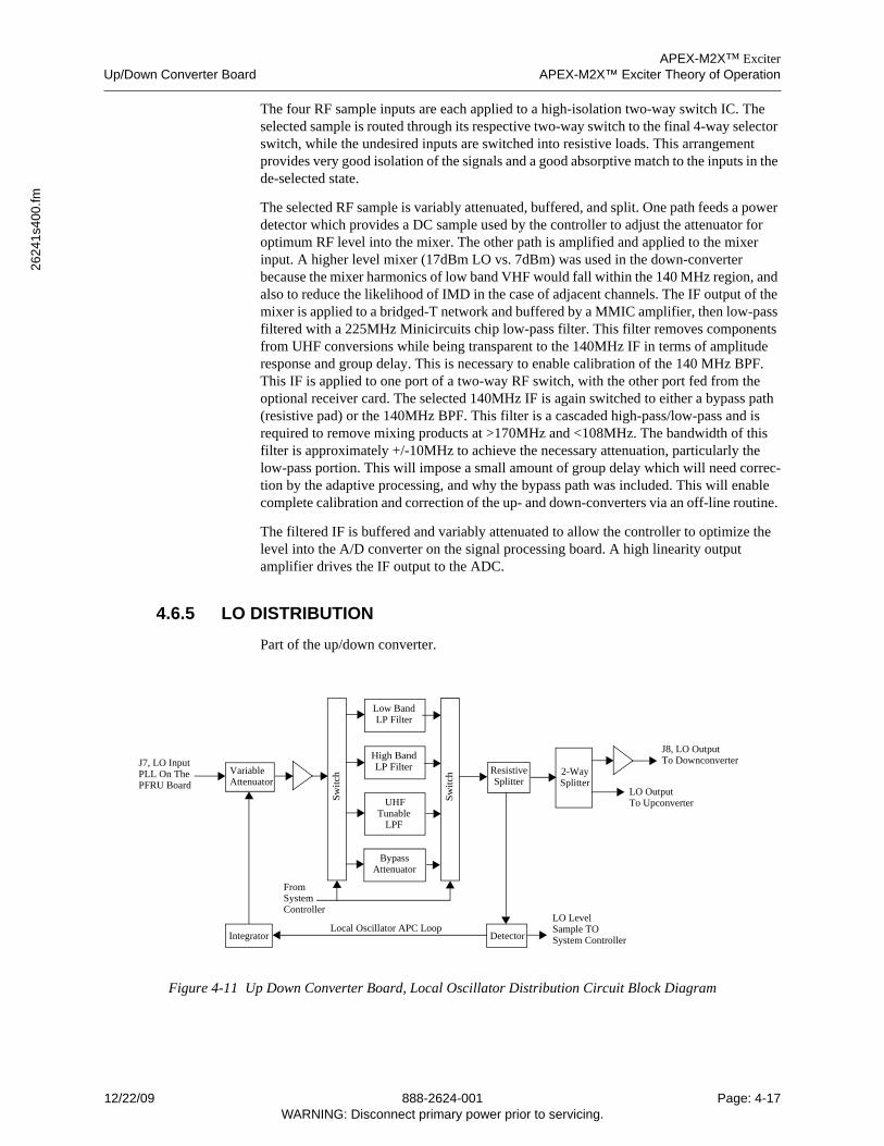
APEX-M2X™ ExciterUp/Down Converter Board APEX-M2X™ Exciter Theory of Operation
2624
1s4
00.fm
The four RF sample inputs are each applied to a high-isolation two-way switch IC. The selected sample is routed through its respective two-way switch to the final 4-way selector switch, while the undesired inputs are switched into resistive loads. This arrangement provides very good isolation of the signals and a good absorptive match to the inputs in the de-selected state.
The selected RF sample is variably attenuated, buffered, and split. One path feeds a power detector which provides a DC sample used by the controller to adjust the attenuator for optimum RF level into the mixer. The other path is amplified and applied to the mixer input. A higher level mixer (17dBm LO vs. 7dBm) was used in the down-converter because the mixer harmonics of low band VHF would fall within the 140 MHz region, and also to reduce the likelihood of IMD in the case of adjacent channels. The IF output of the mixer is applied to a bridged-T network and buffered by a MMIC amplifier, then low-pass filtered with a 225MHz Minicircuits chip low-pass filter. This filter removes components from UHF conversions while being transparent to the 140MHz IF in terms of amplitude response and group delay. This is necessary to enable calibration of the 140 MHz BPF. This IF is applied to one port of a two-way RF switch, with the other port fed from the optional receiver card. The selected 140MHz IF is again switched to either a bypass path (resistive pad) or the 140MHz BPF. This filter is a cascaded high-pass/low-pass and is required to remove mixing products at >170MHz and <108MHz. The bandwidth of this filter is approximately +/-10MHz to achieve the necessary attenuation, particularly the low-pass portion. This will impose a small amount of group delay which will need correc-tion by the adaptive processing, and why the bypass path was included. This will enable complete calibration and correction of the up- and down-converters via an off-line routine.
The filtered IF is buffered and variably attenuated to allow the controller to optimize the level into the A/D converter on the signal processing board. A high linearity output amplifier drives the IF output to the ADC.
4.6.5 LO DISTRIBUTION
Part of the up/down converter.
Figure 4-11 Up Down Converter Board, Local Oscillator Distribution Circuit Block Diagram
VariableAttenuator
J7, LO InputPLL On ThePFRU Board
Detector
Resistive
LO LevelSample TO
Low BandLP Filter
High BandLP Filter
UHFTunable
LPF
Sw
itch
BypassAttenuator
Sw
itch
2-WaySplitterSplitter
IntegratorLocal Oscillator APC Loop
LO OutputTo Upconverter
J8, LO OutputTo Downconverter
FromSystemController
System Controller
12/22/09 888-2624-001 Page: 4-17WARNING: Disconnect primary power prior to servicing.
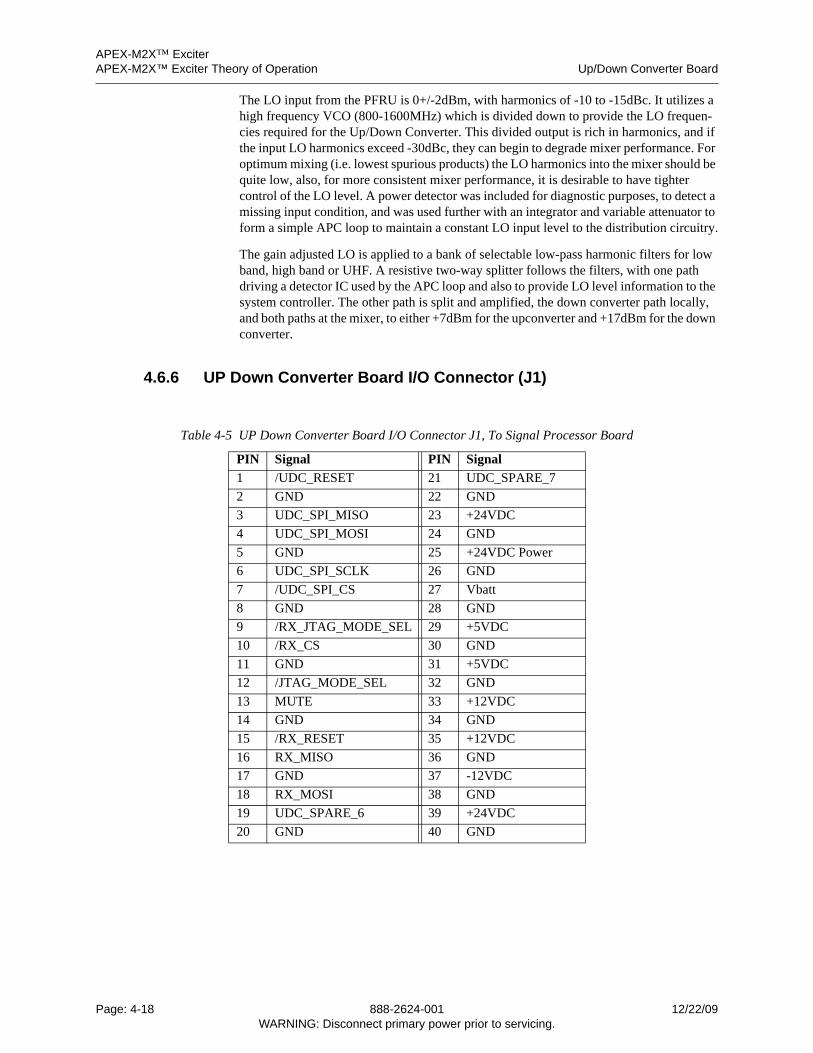
APEX-M2X™ ExciterAPEX-M2X™ Exciter Theory of Operation Up/Down Converter Board
The LO input from the PFRU is 0+/-2dBm, with harmonics of -10 to -15dBc. It utilizes a high frequency VCO (800-1600MHz) which is divided down to provide the LO frequen-cies required for the Up/Down Converter. This divided output is rich in harmonics, and if the input LO harmonics exceed -30dBc, they can begin to degrade mixer performance. For optimum mixing (i.e. lowest spurious products) the LO harmonics into the mixer should be quite low, also, for more consistent mixer performance, it is desirable to have tighter control of the LO level. A power detector was included for diagnostic purposes, to detect a missing input condition, and was used further with an integrator and variable attenuator to form a simple APC loop to maintain a constant LO input level to the distribution circuitry.
The gain adjusted LO is applied to a bank of selectable low-pass harmonic filters for low band, high band or UHF. A resistive two-way splitter follows the filters, with one path driving a detector IC used by the APC loop and also to provide LO level information to the system controller. The other path is split and amplified, the down converter path locally, and both paths at the mixer, to either +7dBm for the upconverter and +17dBm for the down converter.
4.6.6 UP Down Converter Board I/O Connector (J1)
Table 4-5 UP Down Converter Board I/O Connector J1, To Signal Processor Board
PIN Signal PIN Signal
1 /UDC_RESET 21 UDC_SPARE_7
2 GND 22 GND
3 UDC_SPI_MISO 23 +24VDC
4 UDC_SPI_MOSI 24 GND
5 GND 25 +24VDC Power
6 UDC_SPI_SCLK 26 GND
7 /UDC_SPI_CS 27 Vbatt
8 GND 28 GND
9 /RX_JTAG_MODE_SEL 29 +5VDC
10 /RX_CS 30 GND
11 GND 31 +5VDC
12 /JTAG_MODE_SEL 32 GND
13 MUTE 33 +12VDC
14 GND 34 GND
15 /RX_RESET 35 +12VDC
16 RX_MISO 36 GND
17 GND 37 -12VDC
18 RX_MOSI 38 GND
19 UDC_SPARE_6 39 +24VDC
20 GND 40 GND
Page: 4-18 888-2624-001 12/22/09WARNING: Disconnect primary power prior to servicing.
APEX-M2X™ ExciterSignal Processing Board Overview APEX-M2X™ Exciter Theory of Operation
2624
1s4
00.fm
4.7 Signal Processing Board Overview
The signal processing board serves as a motherboard for the UEP exciter. The board inter-faces to all the boards in the exciter.
The signal processing board also serves as the ASI input and output decoder and encoder, the modulator, the digital precorrector (RTAC circuit for digital modulation modes), and it contains the ADC and DAC interfacing to the up / down converter board. The signal processing board interfaces to the transmitter I/O Interface board, the analog input option board, the up / down converter board, the PFRU board, the front panel, and the LVPS.
Power for the signal processing board is derived from the LVPS, which delivers +5Vdc, +12Vdc, -12V, and +24Vdc. All other voltages necessary for the signal processing board are derived from these inputs. All boards within the exciter receive their power through the signal processing board.
Monitoring of the power supplies and ambient temperature are performed by the uC module, which is a daughter board mounted on the top right rear corner of the signal processor board. The uC module also initiates offline tests requested by the user, such as memory tests, serial channel loop back, predefined board level tests, and predefined exciter tests.
4.7.1 ASI / SMPTE 310 Inputs / Output
The modulator FPGA decodes the four ASI inputs and modulates the active input stream with the selected standard. Transformers are used on the input of the ASI data for common mode rejection. Cable equalization circuitry is also used. The ASI inputs to the FPGA are at LVDS levels.
Input choices are shown below, rear panel connec-tors are shown to the right.
• ASI 1/HP 1 (top left connector)
• ASI 2/LP 1 (top left connector)
• SMPTE (310) 1/HP 2 (bottom left connector)
• SMPTE (310) 2/LP 2 (bottom right connec-tor)
• XXX Define Inputs, how are the four inputs programmed for various digital modula-tion systems, and what are they called? ASI 1 = XXX, ASI 2 = xxx SMPTE 310?
The modulator FPGA also provides an ASI monitor output. The ASI monitor output is at LVDS levels from the FPGA. It is then utilized an LVDS driver and transformer per the ASI specification.
The DUC FPGA is responsible for taking the modulated data and applying correction to it. The DUC FPGA output data is then transferred to the DAC to be converter to a 140 MHz IF, which is then up-converted to the on channel frequency.
4.7.1.1 DAC
The DUC writes the 16-bit I and Q data to the AD9779 DAC. The DAC will be clocked by the ~409 to 460 MHz clock from the PFRU. The 1/4 FDAC clock output of the DAC is used
as a clock for the DUC FPGA and the RF Sample ADC. The DAC will provide the Up / Down Converter board with the 140MHz IF.
12/22/09 888-2624-001 Page: 4-19WARNING: Disconnect primary power prior to servicing.
APEX-M2X™ ExciterAPEX-M2X™ Exciter Theory of Operation Analog Input Board Overview
4.7.1.2 ADC
The AD9461 ADC will be clocked by the 1/4 FDAC clock. It will convert the 140 MHz IF from the down converter to a 16 bit sample provided to the DUC FPGA. The ADC will also provide the DUC FPGA with the Sample A/D clock.
4.8 Analog Input Board Overview
The analogue input board (AIB) is an option in the Harris APEX-M2X exciter and serves as analogue front end for main / aux video and main / aux audio signals. In addition it provides a composite audio input (BTSC system) and a video sync output (back porch pulses).
Video signals are conditioned and digitized with 12 bit resolution at 36.4 MHz sample rate, audio data are provided by 24 bit stereo audio ADC’s and the BTSC input signal is digitized with an 16 bit ADC. The clock signal for the audio ADC’s is provided by a PLL locked to the system clock of 36.4 MHz, which itself is locked to the exciter’s 10MHz reference.
For NICAM sound systems the aux audio inputs are used for modulating the NICAM carrier, whereas the main audio input data are fed to the analogue FM modulator.
4.9 Transmitter I/O Panel Overview
The Transmitter I/O board provides the parallel interface to the transmitter. It is a plug in module to the exciter and can be easily adapted to new transmitter technology. The board contains all the digital I/O and analog I/O inputs and outputs necessary to interface the exciter to the transmitter.
This document describes the functional and physical architecture for the Transmitter I/O board in the UEP exciter.
4.9.1 Transmitter I/O Board
The Transmitter I/O board will interface directly to the Harris transmitters through a stacked 25 pin D sub connector. Harris standard UHF transmitters will interface through a 25 position male D sub connector.
Alarm interfaces will also be available on the 25 position female D sub. The pin out of boththese connectors is given in Section 1.7.1, Transmitter I/O Board Option Connectors onpage 1-7.
The interface to VHF and analog transmitters will also utilize signals available on the 25position female D sub connector, but a VHF to UHF Transmitter Interface Adaptor Cableis needed. Information concerning the adaptor cable is given in Section 4.9.4, VHF to UHFTransmitter Interface Adaptor Cable, on page 4-21.
Page: 4-20 888-2624-001 12/22/09WARNING: Disconnect primary power prior to servicing.
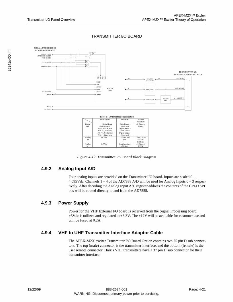
APEX-M2X™ ExciterTransmitter I/O Panel Overview APEX-M2X™ Exciter Theory of Operation
2624
1s4
00.fm
Figure 4-12 Transmitter I/O Board Block Diagram
4.9.2 Analog Input A/D
Four analog inputs are provided on the Transmitter I/O board. Inputs are scaled 0 – 4.095Vdc. Channels 1 – 4 of the AD7888 A/D will be used for Analog Inputs 0 – 3 respec-tively. After decoding the Analog Input A/D register address the contents of the CPLD SPI bus will be routed directly to and from the AD7888.
4.9.3 Power Supply
Power for the VHF External I/O board is received from the Signal Processing board. +5Vdc is utilized and regulated to +3.3V. The +12V will be available for customer use and will be fused at 0.2A.
4.9.4 VHF to UHF Transmitter Interface Adaptor Cable
The APEX-M2X exciter Transmitter I/O Board Option contains two 25 pin D sub connec-tors. The top (male) connector is the transmitter interface, and the bottom (female) is the user remote connector. Harris VHF transmitters have a 37 pin D sub connector for their transmitter interface.
XC9572XLCPLD
/TX IO RESET
JTAG MODE SELECTENB
TX IO SPI SCK
ENB/TX IO SPI CS
ENBTX IO SPI MOSI
TDI
TM
S
TCK
TD
O
ENBTX IO SPI MISO
MISO
SCK
/SPI CS
MOSI
/RESET
MUTE
SPARE SPARE
34
TRANSMITTER I/O BOARD
SIGNAL PROCESSING BOARD INTERFACE
DRIVERS / RECEIVERS
DIGITAL I/O17
TRANSMITTER I/O37 POS D SUB RECEPTACLE
SERIAL D/A
SERIAL A/D
4
4
ANALOG OUT2
ANALOG IN4ANALOG MUX
/UPS OFF
Specification Condition Absolute Maximum
Digital I/O
Digital Input Digital Output
Vih = 3.5Vdc minVoh = 2.4Vdc minVil = 1.35Vdc maxVol= 1.1Vdc max
Digital input –10mA sink
Digital output 2mA source
Digital output –20mA sink
-0 .3Vdc to 15Vdc
Analog Out
0- 5Vdc 2Kohm load min
Short circuit to Gnd -
IndefiniteAnalog
In0- 5Vdc Input impedance
- 2Kohm- 0.3Vdc to
5.5Vdc
Table 1: I/O Interface Specification
8
–
12/22/09 888-2624-001 Page: 4-21WARNING: Disconnect primary power prior to servicing.

APEX-M2X™ ExciterAPEX-M2X™ Exciter Theory of Operation Transmitter I/O Panel Overview
An interface cable is available which has a 37 pin female D sub connector to connect to the VHF transmitter exciter control cable. This cable terminates in a female 25 pin D sub connector for the exciter transmitter I/O board top connector and a male 25 pin D sub connector for the bottom transmitter I/O connector.
Table 1-5, VHF To UHF Interface Cable, on page 1-9 lists the pinout for this interface cable.
Page: 4-22 888-2624-001 12/22/09WARNING: Disconnect primary power prior to servicing.
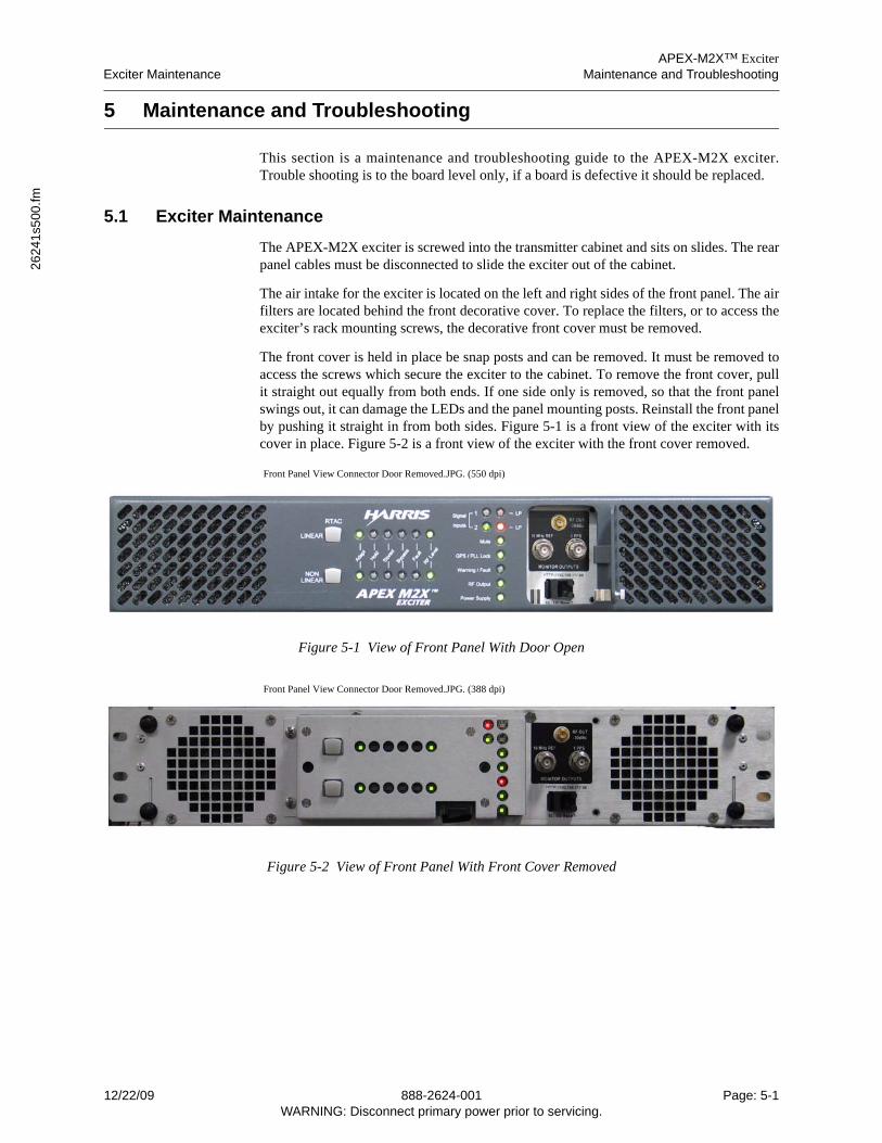
APEX-M2X™ ExciterExciter Maintenance Maintenance and Troubleshooting
2624
1s5
00.fm
5 Maintenance and Troubleshooting
This section is a maintenance and troubleshooting guide to the APEX-M2X exciter.Trouble shooting is to the board level only, if a board is defective it should be replaced.
5.1 Exciter Maintenance
The APEX-M2X exciter is screwed into the transmitter cabinet and sits on slides. The rearpanel cables must be disconnected to slide the exciter out of the cabinet.
The air intake for the exciter is located on the left and right sides of the front panel. The airfilters are located behind the front decorative cover. To replace the filters, or to access theexciter’s rack mounting screws, the decorative front cover must be removed.
The front cover is held in place be snap posts and can be removed. It must be removed toaccess the screws which secure the exciter to the cabinet. To remove the front cover, pullit straight out equally from both ends. If one side only is removed, so that the front panelswings out, it can damage the LEDs and the panel mounting posts. Reinstall the front panelby pushing it straight in from both sides. Figure 5-1 is a front view of the exciter with itscover in place. Figure 5-2 is a front view of the exciter with the front cover removed.
Front Panel View Connector Door Removed.JPG. (550 dpi)
Figure 5-1 View of Front Panel With Door Open
Front Panel View Connector Door Removed.JPG. (388 dpi)
Figure 5-2 View of Front Panel With Front Cover Removed
12/22/09 888-2624-001 Page: 5-1WARNING: Disconnect primary power prior to servicing.
APEX-M2X™ ExciterMaintenance and Troubleshooting Exciter Maintenance
Front Panel View Expanded.JPG. (320 dpi)
Figure 5-3 Expanded View of Front Panel With Door Open
The top cover can be removed to provide access to the circuit boards, see Figure 5-4. Thisdrawing provides the names and locations of the various circuit boards, the ribbon cableboard interconnections, and the RF cabling of the exciter. Figure 5-5 shows the connec-tions between the rear panel transport stream input connectors and the Signal Processorboard.
The exciter consists of 9 circuit boards, which are as follows.
• Signal Processor Board.
• Precise Frequency Reference Unit Board.
• Up Down Converter Board.
• Power Supply and Low Voltage Distribution Board.
• Battery Backup Option Board.
• Front Panel LED and Switch Board.
• Transmitter I/O Interface Board option, piggy backed under the right rear side of the signal processor board. This board can be inserted and removed through the rear pan-el of the exciter.
• Analog Transmitter (Video) Input Board option, piggy backed under the left rear side of the signal processor board. This board can be inserted and removed through the rear panel of the exciter.
• Analog Audio Input Board option, piggy backed under the analog transmitter (video) input board. This board can be inserted and removed through the rear panel of the ex-citer.
Figure 5-6 shows the rear panel of the exciter with its connectors.
Page: 5-2 888-2624-001 12/22/09WARNING: Disconnect primary power prior to servicing.
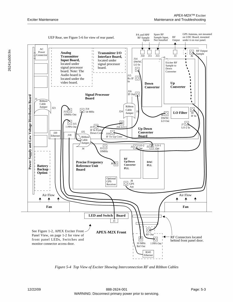
APEX-M2X™ ExciterExciter Maintenance Maintenance and Troubleshooting
2624
1s5
00.fm
ed
Figure 5-4 Top View of Exciter Showing Interconnection RF and Ribbon Cables
Signal ProcessorBoard
AnalogTransmitterInput Board,located undersignal processorboard. Note: The
Transmitter I/OInterface Board,located undersignal processorboard.
Up DownConverter Board
FanFan
Air FlowAir Flow
Precise FrequencyReference UnitBoard
RibbonCableJumper
RibbonCableJumper
BatteryBackupOption
ACPower
Pow
er S
up
ply
an
d L
ow V
olta
ge D
istr
ibut
ion
Boa
rd
UpConverter
DownConverter
LO Filter
PA and HPFRFOutputInputs
Exciter RFSample toDownConverter
Spare RFSample Input,RF Sample
RFDACPLL
Up/DownConverterPLL
OptionalGPSReceiver
J3J1 J2
J8GPSAnt
J6
J1
J23J24 J1
GPS Antenna, not mount
LO-2 LO-1
J1454 MHzJ13
10MHz Out
J151 PPS Out
10MHz
Audio board islocated under thevideo board.
J8DWNCLO Out
J14DWNCLO In
J7LO-2 In
J4IF In
J16 LO-1
J19IF To Up Conv
J17IF In From
Connector
Down Conv
OutOut
Not Installed
J10 J11 J13 J3 J6
on UDC Board, mounted
RF OutputSample
under it on rear panel.
J20Ethernet J18
APEX-M2X Front
LED and Switch
RF Connectors locatedRF Out
10 MHz 1 PPS OutRef Out
behind front panel door.
RJ45Ethernet
J1
Board
UEP Rear, see Figure 5-6 for view of rear panel.
See Figure 1-2, APEX Exciter FrontPanel View, on page 1-2 for view offront panel LEDs, Switches andmonitor connector access door.
RibbonCableJumper
J25
J4
J15Rx IFIn
J16IF Out
12/22/09 888-2624-001 Page: 5-3WARNING: Disconnect primary power prior to servicing.
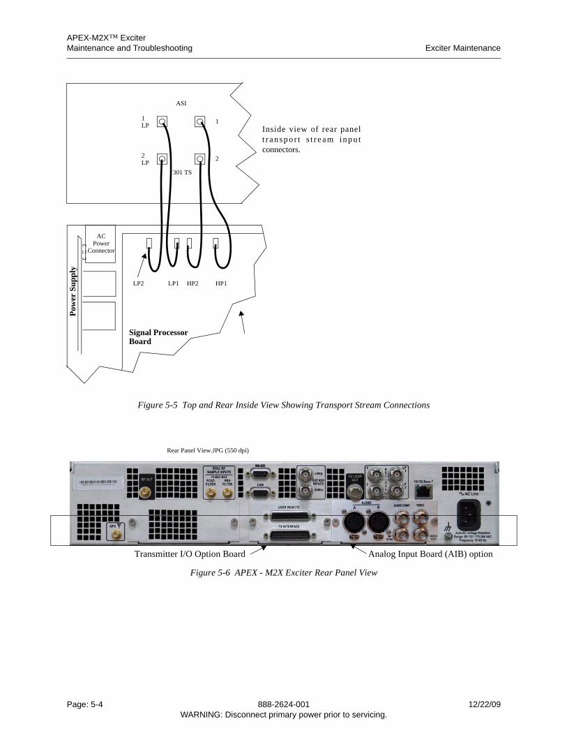
APEX-M2X™ ExciterMaintenance and Troubleshooting Exciter Maintenance
Figure 5-5 Top and Rear Inside View Showing Transport Stream Connections
Rear Panel View.JPG (550 dpi)
Figure 5-6 APEX - M2X Exciter Rear Panel View
Signal ProcessorBoard
ACPower
Pow
er S
up
ply
LP2 LP1
Connector
HP2 HP1
Inside view of rear panelt r anspo r t s t r eam inpu tconnectors.
ASI
1
2
LP
LP
1
2
301 TS
Transmitter I/O Option Board Analog Input Board (AIB) option
Page: 5-4 888-2624-001 12/22/09WARNING: Disconnect primary power prior to servicing.
APEX-M2X™ ExciterLoading Software Maintenance and Troubleshooting
2624
1s5
00.fm
5.1.1 Cleaning
Occasionally the circuit boards of the exciter will need cleaning. All precaution againststatic should be observed. The technician should be grounded, either through conductiveshoes or through a static grounding strap.
The exciter should be powered down before the cleaning process is started. A vacuumcleaner should be used to remove dust from the assemblies. A natural bristle brush with ametal band and a wooden handle (needed to ground static electricity) can be used todislodge dust. A vacuum cleaner hose can develop static due to the air rushing through thehose. The hose should have a metal nozzle, which should be grounded.
Do not use compressed air to blow dirt from the exciter because the dirt will just settle backdown on something else. Also, the fast moving air could damage or dislodge delicatecircuit board components, and it could also accentuate static problems.
5.2 Loading Software
The APEX-M2x exciter software must be occasionally reloaded to update the software tothe latest revision, or if the signal processor board has been changed and contains anincorrect version.
Software loading is covered in Section 2.11, Software Downloads, on page 2-7.
5.3 Changing Date and Time Battery
1 Remove power form the exciter.
2 If exciter is in the transmitter, remove it and set it on a bench.
3 Remove the top cover.
4 Remove old battery and insert new battery with positive side up.
A Battery slides out for under the clip.
1. See Figures 5-7 and 5-8 for battery location.
2. See Figure 5-9 for details of changing battery.
5 Replace top of exciter and remount it in the transmitter.
6 Continue on to the next section to set the time and date.
The part number for the date and time battery is 660-0093-000.
5.3.1 Setting Date and Time After Battery Replacement
The date and time must be set in the exciter after the date and time battery has beeninstalled. Use the following procedure to set the date an time.
1 Log in to the exciter using the front or rear ethernet connectors.
2 In the Exciter Setup > Exciter Setup screen.
3 In the Exciter Setup screen, click in each box.
A A keyboard will appear. Type in the value for that box, then press enter.
B Repeat step A for each box.
C The time is entered in the 24 hour format.
12/22/09 888-2624-001 Page: 5-5WARNING: Disconnect primary power prior to servicing.
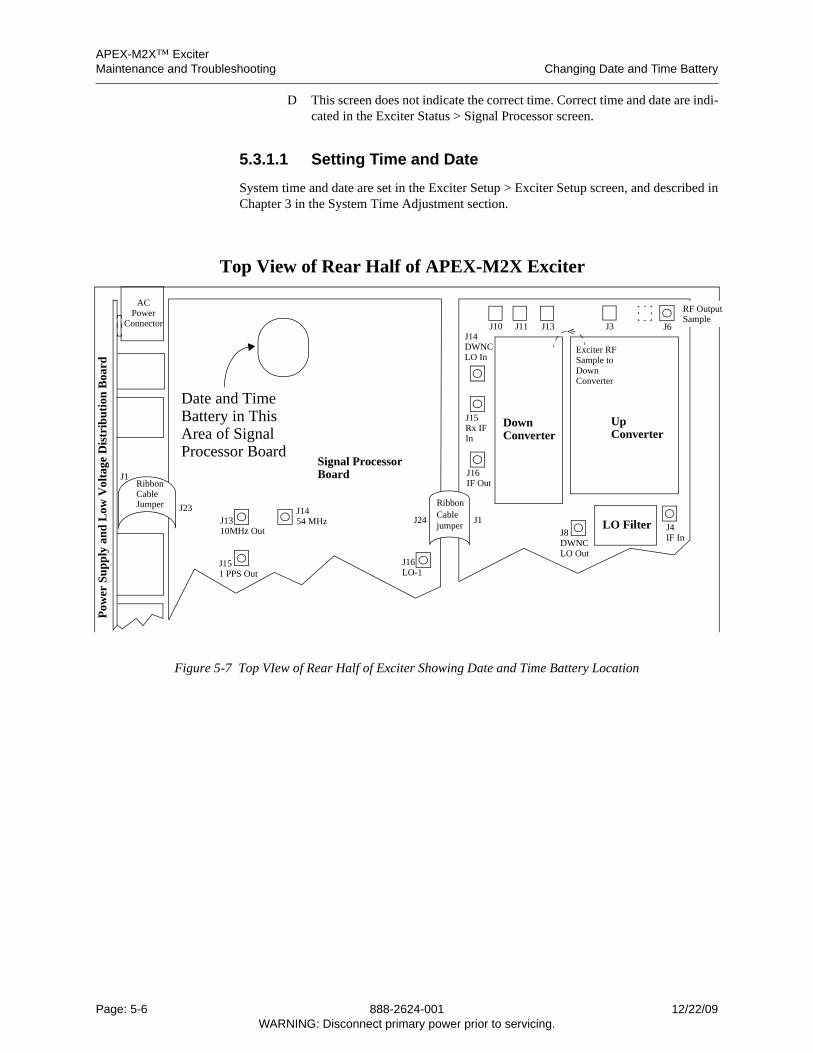
APEX-M2X™ ExciterMaintenance and Troubleshooting Changing Date and Time Battery
D This screen does not indicate the correct time. Correct time and date are indi-cated in the Exciter Status > Signal Processor screen.
5.3.1.1 Setting Time and Date
System time and date are set in the Exciter Setup > Exciter Setup screen, and described inChapter 3 in the System Time Adjustment section.
Figure 5-7 Top VIew of Rear Half of Exciter Showing Date and Time Battery Location
Signal ProcessorBoard
RibbonCablejumper
RibbonCableJumper
ACPower
Pow
er S
up
ply
an
d L
ow V
olta
ge D
istr
ibut
ion
Boa
rd
UpConverter
DownConverter
LO Filter
Exciter RFSample toDownConverter
J1
J23J24 J1
J1454 MHzJ13
10MHz Out
J151 PPS Out
J8DWNCLO Out
J14DWNCLO In
J15Rx IFIn
J4IF In
J16IF Out
J16LO-1
Connector J10 J11 J13 J3 J6
RF OutputSample
Top View of Rear Half of APEX-M2X Exciter
Date and TimeBattery in ThisArea of SignalProcessor Board
Page: 5-6 888-2624-001 12/22/09WARNING: Disconnect primary power prior to servicing.
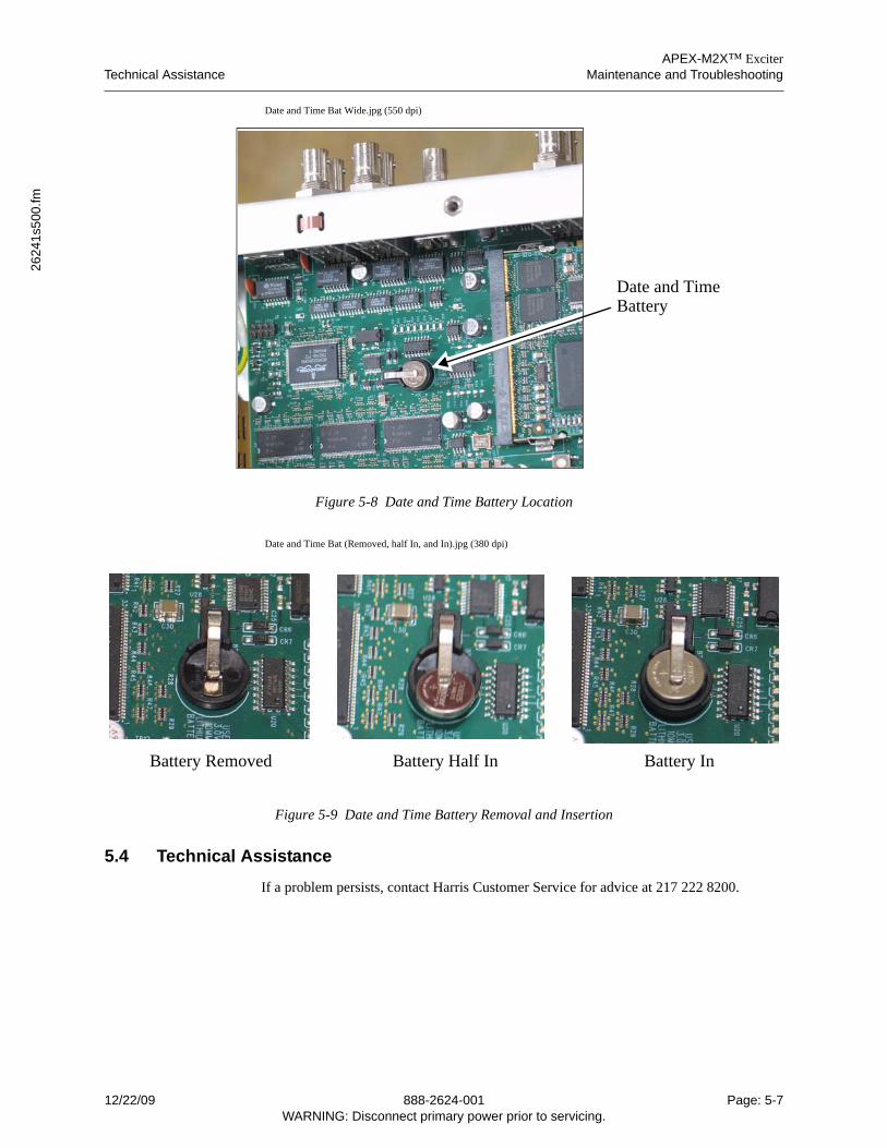
APEX-M2X™ ExciterTechnical Assistance Maintenance and Troubleshooting
2624
1s5
00.fm
Date and Time Bat Wide.jpg (550 dpi)
Figure 5-8 Date and Time Battery Location
Date and Time Bat (Removed, half In, and In).jpg (380 dpi)
Figure 5-9 Date and Time Battery Removal and Insertion
5.4 Technical Assistance
If a problem persists, contact Harris Customer Service for advice at 217 222 8200.
Date and TimeBattery
Battery Removed Battery Half In Battery In
12/22/09 888-2624-001 Page: 5-7WARNING: Disconnect primary power prior to servicing.

APEX-M2X™ ExciterMaintenance and Troubleshooting Technical Assistance
Page: 5-8 888-2624-001 12/22/09WARNING: Disconnect primary power prior to servicing.
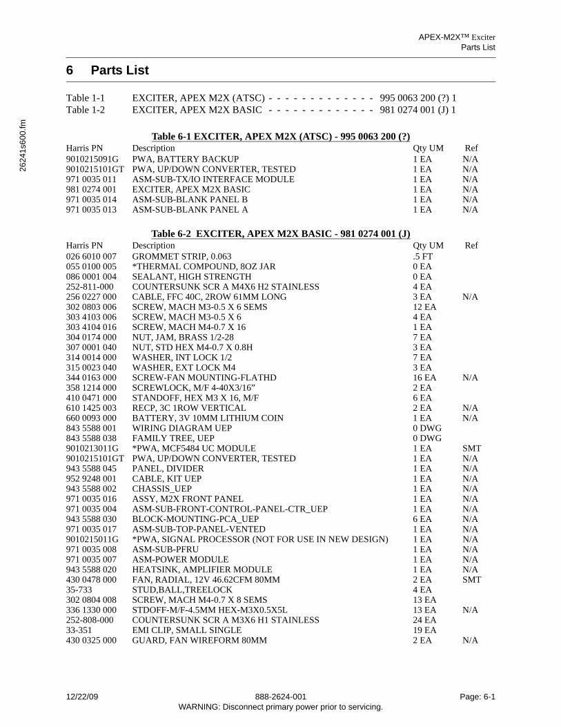
APEX-M2X™ ExciterParts List
2624
1s6
00.fm
6 Parts List
Table 1-1 EXCITER, APEX M2X (ATSC) - - - - - - - - - - - - - 995 0063 200 (?) 1Table 1-2 EXCITER, APEX M2X BASIC - - - - - - - - - - - - - 981 0274 001 (J) 1
Table 6-1 EXCITER, APEX M2X (ATSC) - 995 0063 200 (?)Harris PN Description Qty UM Ref9010215091G PWA, BATTERY BACKUP 1 EA N/A9010215101GT PWA, UP/DOWN CONVERTER, TESTED 1 EA N/A971 0035 011 ASM-SUB-TX/IO INTERFACE MODULE 1 EA N/A981 0274 001 EXCITER, APEX M2X BASIC 1 EA N/A971 0035 014 ASM-SUB-BLANK PANEL B 1 EA N/A971 0035 013 ASM-SUB-BLANK PANEL A 1 EA N/A
Table 6-2 EXCITER, APEX M2X BASIC - 981 0274 001 (J)Harris PN Description Qty UM Ref026 6010 007 GROMMET STRIP, 0.063 .5 FT055 0100 005 *THERMAL COMPOUND, 8OZ JAR 0 EA086 0001 004 SEALANT, HIGH STRENGTH 0 EA252-811-000 COUNTERSUNK SCR A M4X6 H2 STAINLESS 4 EA256 0227 000 CABLE, FFC 40C, 2ROW 61MM LONG 3 EA N/A302 0803 006 SCREW, MACH M3-0.5 X 6 SEMS 12 EA303 4103 006 SCREW, MACH M3-0.5 X 6 4 EA303 4104 016 SCREW, MACH M4-0.7 X 16 1 EA304 0174 000 NUT, JAM, BRASS 1/2-28 7 EA307 0001 040 NUT, STD HEX M4-0.7 X 0.8H 3 EA314 0014 000 WASHER, INT LOCK 1/2 7 EA315 0023 040 WASHER, EXT LOCK M4 3 EA344 0163 000 SCREW-FAN MOUNTING-FLATHD 16 EA N/A358 1214 000 SCREWLOCK, M/F 4-40X3/16” 2 EA410 0471 000 STANDOFF, HEX M3 X 16, M/F 6 EA610 1425 003 RECP, 3C 1ROW VERTICAL 2 EA N/A660 0093 000 BATTERY, 3V 10MM LITHIUM COIN 1 EA N/A843 5588 001 WIRING DIAGRAM UEP 0 DWG843 5588 038 FAMILY TREE, UEP 0 DWG9010213011G *PWA, MCF5484 UC MODULE 1 EA SMT9010215101GT PWA, UP/DOWN CONVERTER, TESTED 1 EA N/A943 5588 045 PANEL, DIVIDER 1 EA N/A952 9248 001 CABLE, KIT UEP 1 EA N/A943 5588 002 CHASSIS_UEP 1 EA N/A971 0035 016 ASSY, M2X FRONT PANEL 1 EA N/A971 0035 004 ASM-SUB-FRONT-CONTROL-PANEL-CTR_UEP 1 EA N/A943 5588 030 BLOCK-MOUNTING-PCA_UEP 6 EA N/A971 0035 017 ASM-SUB-TOP-PANEL-VENTED 1 EA N/A9010215011G *PWA, SIGNAL PROCESSOR (NOT FOR USE IN NEW DESIGN) 1 EA N/A971 0035 008 ASM-SUB-PFRU 1 EA N/A971 0035 007 ASM-POWER MODULE 1 EA N/A943 5588 020 HEATSINK, AMPLIFIER MODULE 1 EA N/A430 0478 000 FAN, RADIAL, 12V 46.62CFM 80MM 2 EA SMT35-733 STUD,BALL,TREELOCK 4 EA302 0804 008 SCREW, MACH M4-0.7 X 8 SEMS 13 EA336 1330 000 STDOFF-M/F-4.5MM HEX-M3X0.5X5L 13 EA N/A252-808-000 COUNTERSUNK SCR A M3X6 H1 STAINLESS 24 EA33-351 EMI CLIP, SMALL SINGLE 19 EA430 0325 000 GUARD, FAN WIREFORM 80MM 2 EA N/A
12/22/09 888-2624-001 Page: 6-1WARNING: Disconnect primary power prior to servicing.

APEX-M2X™ ExciterParts List
Page: 6-2 888-2624-001 12/22/09WARNING: Disconnect primary power prior to servicing.
APEX-M2X™ ExciterIntroduction APEX-M2X Exciter Quick Start Guide
2624
1sa
pa.fm
Appendix A APEX-M2X Exciter Quick Start Guide
A.1 Introduction
This guide provides an outline of activities required to install and activate a M2X exciter inan existing Harris transmitter and in new Harris transmitter systems. This document isintended to be a guide to the initial programming of the exciter. It does not cover all of theexciter programming, but only that which could be detrimental to the operation of thetransmitter.
CautionThis procedure is a general outline for activating a transmitterwhich includes the APEX-M2X exciter and is not intended to re-place the more detailed information and procedures in theAPEX-M2X exciter technical manual and the appropriate transmit-ter technical manuals. The transmitter and exciter technical manu-als installation, adjustment and checkout procedures should bestudied and thoroughly understood before attempting to setup andoperate a new transmitter or exciter.
When retrofit into an existing transmitter, the APEX-M2X exciter on site checkout needsto be done in two parts.
• First it is necessary to bench test the exciter in order to verify its RF frequency, set its RF output power, and set the other more critical parameters.
• Next, it is installed in the transmitter to complete the exciter setup and monitor its per-formance.
A.2 Retrofit Kits For APEX-M2X Exciters
Exciters sold for retrofit into existing transmitter systems will require appropriatemounting hardware, and also requires two RF Output feedback samples.
A.2.1 CD-1A to APEX-M2X Exciter Retrofits
The following kits are required if retrofitting APEX-M2X exciters in place of one or twoCD-1A exciters. These kits provide the materials necessary to retrofit two exciters, and areneeded if both are CD-1A exciters or if the transmitter contains only one exciter (a CD-1A)and a space for a second CD-1A. The kit numbers are as follows.
• 971-0061-001, Field Upgrade Kit, APEX-M2X Exciter Into Platinum Tx.Note: This upgrade does not apply to the Platinum i control cabinet, the Platinum i control cabinet was never fitted with CD-1A exciters.
• 971-0061-002, Field Upgrade Kit, APEX-M2X Exciter Into Diamond or Sigma Tx.
A.2.2 APEX-M2X Exciter Retrofit in a Ranger Transmitter
The exciter retrofit kit for a ranger transmitter is:
971-0061-005, Field Upgrade Kit, APEX-M2X Exciter Into Ranger Tx.
This kit is good when upgrading from either a CD-1A or Classic Apex exciter.
12/22/09 888-2624-001 Page: A-1WARNING: Disconnect primary power prior to servicing.
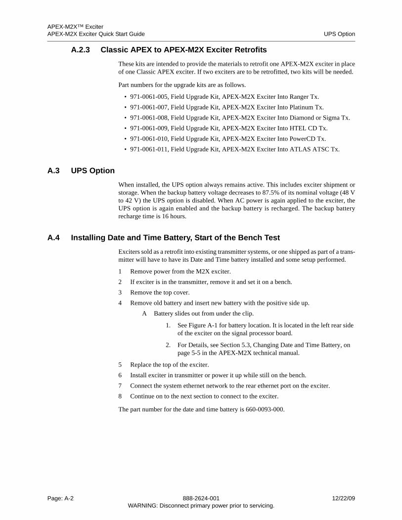
APEX-M2X™ ExciterAPEX-M2X Exciter Quick Start Guide UPS Option
A.2.3 Classic APEX to APEX-M2X Exciter Retrofits
These kits are intended to provide the materials to retrofit one APEX-M2X exciter in placeof one Classic APEX exciter. If two exciters are to be retrofitted, two kits will be needed.
Part numbers for the upgrade kits are as follows.
• 971-0061-005, Field Upgrade Kit, APEX-M2X Exciter Into Ranger Tx.
• 971-0061-007, Field Upgrade Kit, APEX-M2X Exciter Into Platinum Tx.
• 971-0061-008, Field Upgrade Kit, APEX-M2X Exciter Into Diamond or Sigma Tx.
• 971-0061-009, Field Upgrade Kit, APEX-M2X Exciter Into HTEL CD Tx.
• 971-0061-010, Field Upgrade Kit, APEX-M2X Exciter Into PowerCD Tx.
• 971-0061-011, Field Upgrade Kit, APEX-M2X Exciter Into ATLAS ATSC Tx.
A.3 UPS Option
When installed, the UPS option always remains active. This includes exciter shipment orstorage. When the backup battery voltage decreases to 87.5% of its nominal voltage (48 Vto 42 V) the UPS option is disabled. When AC power is again applied to the exciter, theUPS option is again enabled and the backup battery is recharged. The backup batteryrecharge time is 16 hours.
A.4 Installing Date and Time Battery, Start of the Bench Test
Exciters sold as a retrofit into existing transmitter systems, or one shipped as part of a trans-mitter will have to have its Date and Time battery installed and some setup performed.
1 Remove power from the M2X exciter.
2 If exciter is in the transmitter, remove it and set it on a bench.
3 Remove the top cover.
4 Remove old battery and insert new battery with the positive side up.
A Battery slides out from under the clip.
1. See Figure A-1 for battery location. It is located in the left rear side of the exciter on the signal processor board.
2. For Details, see Section 5.3, Changing Date and Time Battery, on page 5-5 in the APEX-M2X technical manual.
5 Replace the top of the exciter.
6 Install exciter in transmitter or power it up while still on the bench.
7 Connect the system ethernet network to the rear ethernet port on the exciter.
8 Continue on to the next section to connect to the exciter.
The part number for the date and time battery is 660-0093-000.
Page: A-2 888-2624-001 12/22/09WARNING: Disconnect primary power prior to servicing.
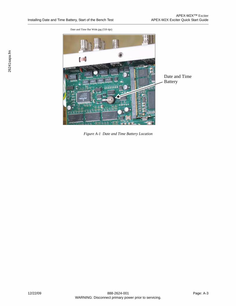
APEX-M2X™ ExciterInstalling Date and Time Battery, Start of the Bench Test APEX-M2X Exciter Quick Start Guide
2624
1sa
pa.fm
Date and Time Bat Wide.jpg (550 dpi)
Figure A-1 Date and Time Battery Location
Date and TimeBattery
12/22/09 888-2624-001 Page: A-3WARNING: Disconnect primary power prior to servicing.
APEX-M2X™ ExciterAPEX-M2X Exciter Quick Start Guide Initial Ethernet Connection to the APEX-M2X Exciter, Bench Test Continued
A.5 Initial Ethernet Connection to the APEX-M2X Exciter, Bench Test Continued
The APEX-M2X exciter is configured and operated from a computer which is connectedto the APEX-M2X exciter front or rear panel RJ45 ethernet connectors.
A.5.1 Connection Through The Exciter Front Ethernet Connector
When connecting to the exciter front panel RJ45 connector, if the computer being useddoes not auto-detect for cross connection, a crossover cable must be used to connect theexciter front ethernet port to the computer.
The computer should be setup as a DHCP client. The DHCP server associated with theexciter front RJ45 port will assign an address (192.168.117.135) to the computer. Thismethod of obtaining a computer address is described in Section 2.6.1, Obtaining AddressWith Computer in DHCP Client Mode, on page 2-3 in the exciter technical manual.
The front panel ethernet address is 192.168.117.88.
Connect to the exciter front panel ethernet port using the following procedure.
1 Connect an ethernet cable between the computer’s RJ45 connector and the exciter front panel RJ45 connector.
A If the computer being used does not auto-detect for cross connection, a crossover cable must be used to connect the exciter front ethernet port to the computer.
B It may be necessary to reboot the computer so that the exciter will assign it an appropriate address.
2 Go to Internet Explorer and type the exciter’s front connector address (192.168.117.88).
3 The Log In Screen should appear.
4 Log in using user name and password.
A For user1, the default user name is admin and the password is admin. For user2 the user name is user2 and the password is pass2.
B If an improper user name or password, each three or more characters with no spaces, is entered the monitor login is activated.
C Provisions to change the login user names and passwords are given in Sec-tion 2.4, Exciter Log In Authorization Levels, on page 2-2.
5 The exciter web GUI is now displayed and can be navigated as needed.
A.5.1.1 Obtaining Exciter Rear Ethernet Connector Address
An ethernet network which is driven by a DHCP server will supply the exciter rear ethernetconnector with an appropriate IP address when the rear port is in the DHCP client mode.
The exciter rear RJ45 connector should have already been connected to the existingethernet.
Connect a computer to the exciter front panel RJ45 connector and log in as shown above.
1 Make sure the M2X exciter rear ethernet port is connected to the local ethernet net-work.
2 Navigate to the Exciter Setup > Communications Tab.
Page: A-4 888-2624-001 12/22/09WARNING: Disconnect primary power prior to servicing.
APEX-M2X™ ExciterInitial APEX Exciter Programming, Bench Test Continued APEX-M2X Exciter Quick Start Guide
2624
1sa
pa.fm
3 The rear panel ethernet connector address will be given on this page in the Ethernet #2 sub window.
4 The Ethernet #1 window gives the front ethernet port parameters.
A.5.2 Connecting To The Exciter Through An Existing Ethernet Network
When connecting to an exciter through an existing ethernet network, the connectingcomputer must be setup as a DHCP client so the network can assign it an address.
1 Connect the exciter rear RJ45 connector to the existing ethernet network.
2 Connect the computer to a connector on the existing ethernet network.
3 Go to Internet Explorer and type the exciter rear RJ45 connector address.
4 Log In Screen should appear.
5 Log in using the user name and password. The default login is admin, admin.
6 The exciter web GUI is now displayed and can be navigated as needed.
A.6 Initial APEX Exciter Programming, Bench Test Continued
It is desirable to check or set up the functions listed below while preforming the exciterbench test. These functions can be checked with the exciter mounted in and connected tothe transmitter, but be sure not to set the transmitter to the transmit mode before checkingthese parameters.
A.6.1 Setting RF Output and Offset Frequencies
Before allowing the exciter to drive the transmitter RF amplifiers, its RF frequency shouldbe checked. This can be accomplished by the following procedure.
1 Log into the exciter using an ethernet connection.
2 Navigate to the PFRU (precise frequency reference unit) Setup screen.
A This screen is shown in Figure A-2.
3 Verify that the center frequency and frequency offset entered in their respective win-dows are correct.
A If the frequency information is incorrect or if changes are desired, continue with the rest of this procedure
4 Click in the Frequency window.
5 Type in the Frequency in MHz.
A The Frequency is entered in 1 MHz steps.
B The Frequency limit is 57 to 1492 MHz.
C A fractional part of a MHz is entered by using the Frequency Offset window
D For digital channels, this will be the channel center frequency.
E For analog channels, this will be the visual carrier frequency.
6 If an RF frequency offset is required, click in the Frequency Offset window.
7 Type in the RF frequency offset in Hz.
A The practical limit of the frequency offset is +/-500000 Hz.
B If no offset is required, enter 0.0 Hz.
12/22/09 888-2624-001 Page: A-5WARNING: Disconnect primary power prior to servicing.
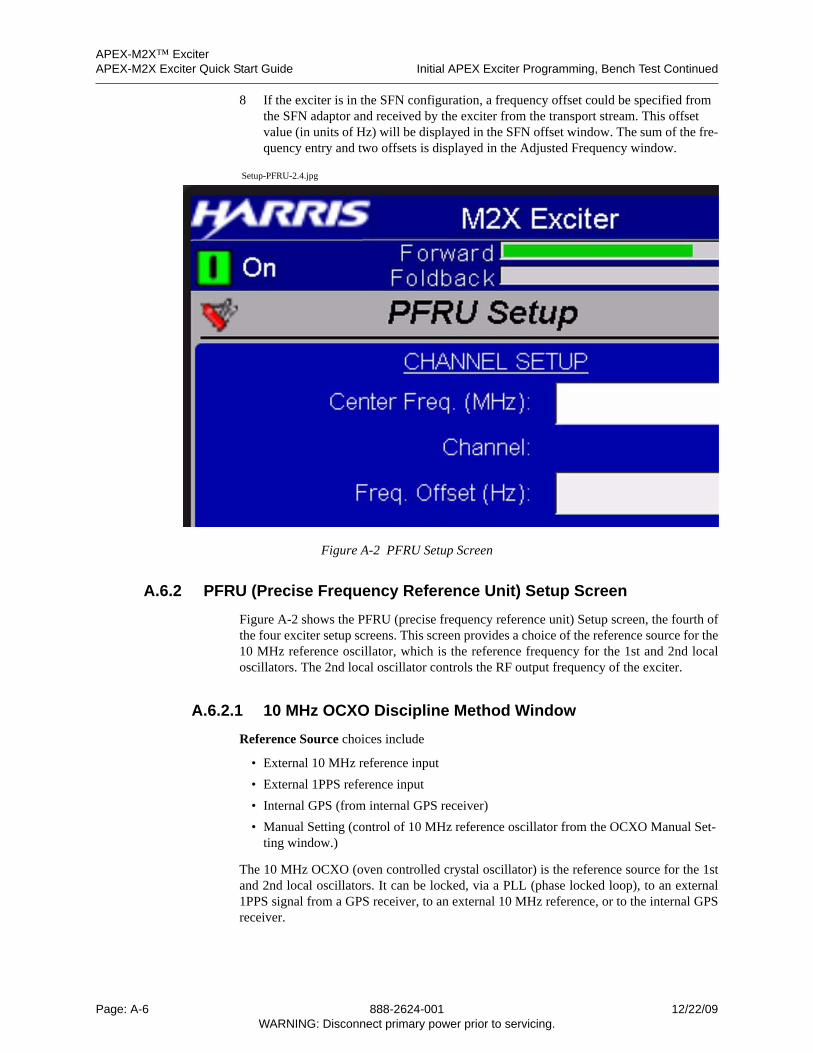
APEX-M2X™ ExciterAPEX-M2X Exciter Quick Start Guide Initial APEX Exciter Programming, Bench Test Continued
8 If the exciter is in the SFN configuration, a frequency offset could be specified from the SFN adaptor and received by the exciter from the transport stream. This offset value (in units of Hz) will be displayed in the SFN offset window. The sum of the fre-quency entry and two offsets is displayed in the Adjusted Frequency window.
Setup-PFRU-2.4.jpg
Figure A-2 PFRU Setup Screen
A.6.2 PFRU (Precise Frequency Reference Unit) Setup Screen
Figure A-2 shows the PFRU (precise frequency reference unit) Setup screen, the fourth ofthe four exciter setup screens. This screen provides a choice of the reference source for the10 MHz reference oscillator, which is the reference frequency for the 1st and 2nd localoscillators. The 2nd local oscillator controls the RF output frequency of the exciter.
A.6.2.1 10 MHz OCXO Discipline Method Window
Reference Source choices include
• External 10 MHz reference input
• External 1PPS reference input
• Internal GPS (from internal GPS receiver)
• Manual Setting (control of 10 MHz reference oscillator from the OCXO Manual Set-ting window.)
The 10 MHz OCXO (oven controlled crystal oscillator) is the reference source for the 1stand 2nd local oscillators. It can be locked, via a PLL (phase locked loop), to an external1PPS signal from a GPS receiver, to an external 10 MHz reference, or to the internal GPSreceiver.
Page: A-6 888-2624-001 12/22/09WARNING: Disconnect primary power prior to servicing.
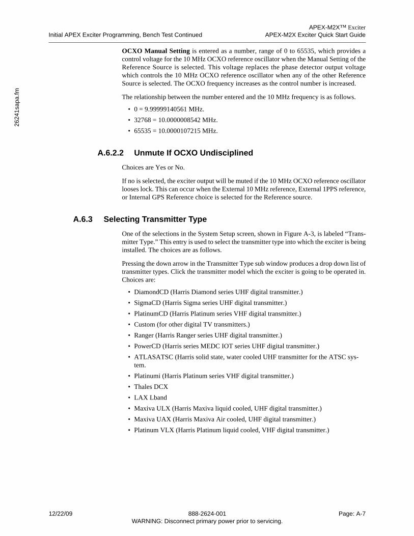
APEX-M2X™ ExciterInitial APEX Exciter Programming, Bench Test Continued APEX-M2X Exciter Quick Start Guide
2624
1sa
pa.fm
OCXO Manual Setting is entered as a number, range of 0 to 65535, which provides acontrol voltage for the 10 MHz OCXO reference oscillator when the Manual Setting of theReference Source is selected. This voltage replaces the phase detector output voltagewhich controls the 10 MHz OCXO reference oscillator when any of the other ReferenceSource is selected. The OCXO frequency increases as the control number is increased.
The relationship between the number entered and the 10 MHz frequency is as follows.
• 0 = 9.99999140561 MHz.
• 32768 = 10.0000008542 MHz.
• 65535 = 10.0000107215 MHz.
A.6.2.2 Unmute If OCXO Undisciplined
Choices are Yes or No.
If no is selected, the exciter output will be muted if the 10 MHz OCXO reference oscillatorlooses lock. This can occur when the External 10 MHz reference, External 1PPS reference,or Internal GPS Reference choice is selected for the Reference source.
A.6.3 Selecting Transmitter Type
One of the selections in the System Setup screen, shown in Figure A-3, is labeled “Trans-mitter Type.” This entry is used to select the transmitter type into which the exciter is beinginstalled. The choices are as follows.
Pressing the down arrow in the Transmitter Type sub window produces a drop down list oftransmitter types. Click the transmitter model which the exciter is going to be operated in.Choices are:
• DiamondCD (Harris Diamond series UHF digital transmitter.)
• SigmaCD (Harris Sigma series UHF digital transmitter.)
• PlatinumCD (Harris Platinum series VHF digital transmitter.)
• Custom (for other digital TV transmitters.)
• Ranger (Harris Ranger series UHF digital transmitter.)
• PowerCD (Harris series MEDC IOT series UHF digital transmitter.)
• ATLASATSC (Harris solid state, water cooled UHF transmitter for the ATSC sys-tem.
• Platinumi (Harris Platinum series VHF digital transmitter.)
• Thales DCX
• LAX Lband
• Maxiva ULX (Harris Maxiva liquid cooled, UHF digital transmitter.)
• Maxiva UAX (Harris Maxiva Air cooled, UHF digital transmitter.)
• Platinum VLX (Harris Platinum liquid cooled, VHF digital transmitter.)
12/22/09 888-2624-001 Page: A-7WARNING: Disconnect primary power prior to servicing.
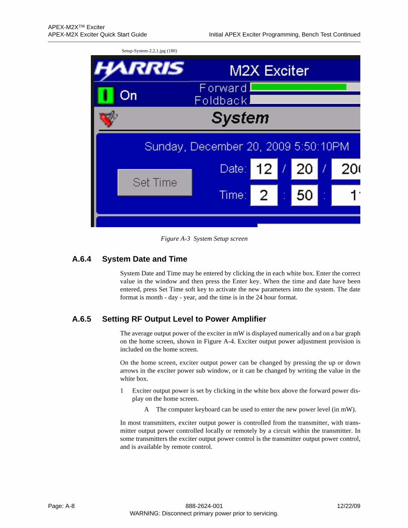
APEX-M2X™ ExciterAPEX-M2X Exciter Quick Start Guide Initial APEX Exciter Programming, Bench Test Continued
Setup-System-2,2,1.jpg (180)
Figure A-3 System Setup screen
A.6.4 System Date and Time
System Date and Time may be entered by clicking the in each white box. Enter the correctvalue in the window and then press the Enter key. When the time and date have beenentered, press Set Time soft key to activate the new parameters into the system. The dateformat is month - day - year, and the time is in the 24 hour format.
A.6.5 Setting RF Output Level to Power Amplifier
The average output power of the exciter in mW is displayed numerically and on a bar graphon the home screen, shown in Figure A-4. Exciter output power adjustment provision isincluded on the home screen.
On the home screen, exciter output power can be changed by pressing the up or downarrows in the exciter power sub window, or it can be changed by writing the value in thewhite box.
1 Exciter output power is set by clicking in the white box above the forward power dis-play on the home screen.
A The computer keyboard can be used to enter the new power level (in mW).
In most transmitters, exciter output power is controlled from the transmitter, with trans-mitter output power controlled locally or remotely by a circuit within the transmitter. Insome transmitters the exciter output power control is the transmitter output power control,and is available by remote control.
Page: A-8 888-2624-001 12/22/09WARNING: Disconnect primary power prior to servicing.
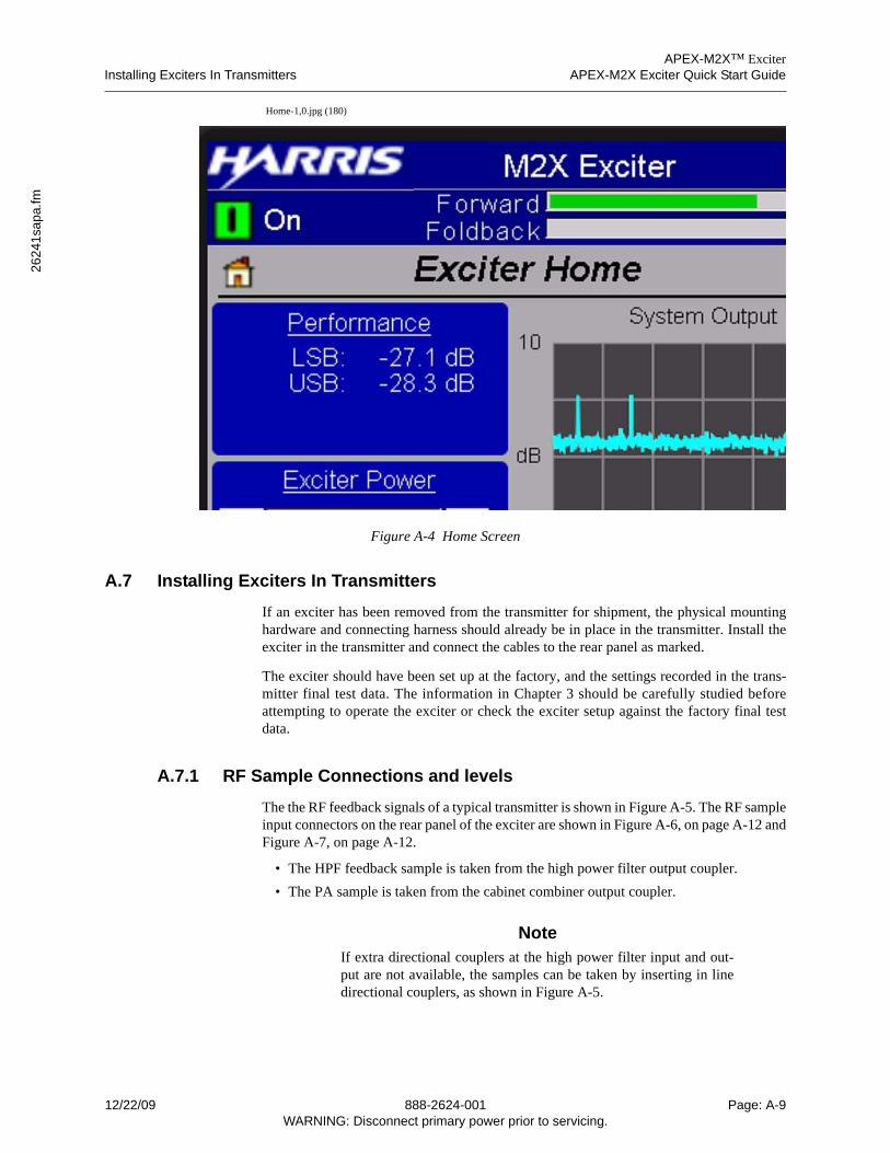
APEX-M2X™ ExciterInstalling Exciters In Transmitters APEX-M2X Exciter Quick Start Guide
2624
1sa
pa.fm
Home-1,0.jpg (180)
Figure A-4 Home Screen
A.7 Installing Exciters In Transmitters
If an exciter has been removed from the transmitter for shipment, the physical mountinghardware and connecting harness should already be in place in the transmitter. Install theexciter in the transmitter and connect the cables to the rear panel as marked.
The exciter should have been set up at the factory, and the settings recorded in the trans-mitter final test data. The information in Chapter 3 should be carefully studied beforeattempting to operate the exciter or check the exciter setup against the factory final testdata.
A.7.1 RF Sample Connections and levels
The the RF feedback signals of a typical transmitter is shown in Figure A-5. The RF sampleinput connectors on the rear panel of the exciter are shown in Figure A-6, on page A-12 andFigure A-7, on page A-12.
• The HPF feedback sample is taken from the high power filter output coupler.
• The PA sample is taken from the cabinet combiner output coupler.
NoteIf extra directional couplers at the high power filter input and out-put are not available, the samples can be taken by inserting in linedirectional couplers, as shown in Figure A-5.
12/22/09 888-2624-001 Page: A-9WARNING: Disconnect primary power prior to servicing.
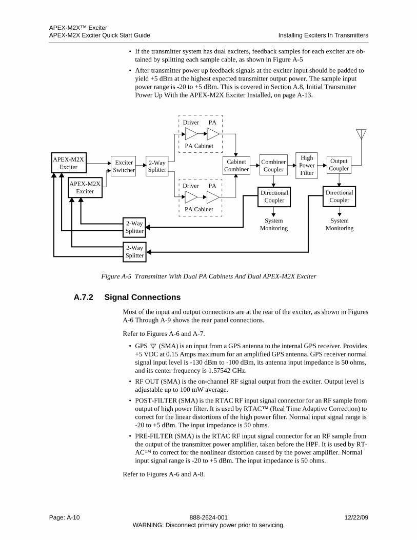
APEX-M2X™ ExciterAPEX-M2X Exciter Quick Start Guide Installing Exciters In Transmitters
• If the transmitter system has dual exciters, feedback samples for each exciter are ob-tained by splitting each sample cable, as shown in Figure A-5
• After transmitter power up feedback signals at the exciter input should be padded to yield +5 dBm at the highest expected transmitter output power. The sample input power range is -20 to +5 dBm. This is covered in Section A.8, Initial Transmitter Power Up With the APEX-M2X Exciter Installed, on page A-13.
Figure A-5 Transmitter With Dual PA Cabinets And Dual APEX-M2X Exciter
A.7.2 Signal Connections
Most of the input and output connections are at the rear of the exciter, as shown in FiguresA-6 Through A-9 shows the rear panel connections.
Refer to Figures A-6 and A-7.
• GPS (SMA) is an input from a GPS antenna to the internal GPS receiver. Provides +5 VDC at 0.15 Amps maximum for an amplified GPS antenna. GPS receiver normal signal input level is -130 dBm to -100 dBm, its antenna input impedance is 50 ohms, and its center frequency is 1.57542 GHz.
• RF OUT (SMA) is the on-channel RF signal output from the exciter. Output level is adjustable up to 100 mW average.
• POST-FILTER (SMA) is the RTAC RF input signal connector for an RF sample from output of high power filter. It is used by RTAC™ (Real Time Adaptive Correction) to correct for the linear distortions of the high power filter. Normal input signal range is -20 to +5 dBm. The input impedance is 50 ohms.
• PRE-FILTER (SMA) is the RTAC RF input signal connector for an RF sample from the output of the transmitter power amplifier, taken before the HPF. It is used by RT-AC™ to correct for the nonlinear distortion caused by the power amplifier. Normal input signal range is -20 to +5 dBm. The input impedance is 50 ohms.
Refer to Figures A-6 and A-8.
OutputCoupler
HighPower
CombinerCoupler
CabinetCombiner
DirectionalCoupler
DirectionalCoupler
Filter
SystemMonitoring
SystemMonitoring
PADriver
PA Cabinet
PADriver
PA Cabinet
ExciterSwitcher
APEX-M2XExciter
APEX-M2XExciter
2-WaySplitter
2-WaySplitter
2-WaySplitter
Page: A-10 888-2624-001 12/22/09WARNING: Disconnect primary power prior to servicing.
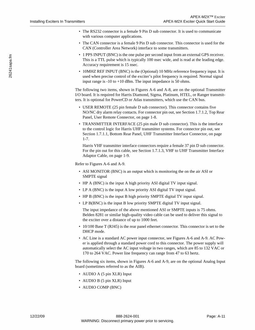
APEX-M2X™ ExciterInstalling Exciters In Transmitters APEX-M2X Exciter Quick Start Guide
2624
1sa
pa.fm
• The RS232 connector is a female 9 Pin D sub connector. It is used to communicate with various computer applications.
• The CAN connector is a female 9 Pin D sub connector. This connector is used for the CAN (Controller Area Network) interface to some transmitters.
• 1 PPS INPUT (BNC) is the one pulse per second input from an external GPS receiver. This is a TTL pulse which is typically 100 nsec wide, and is read at the leading edge. Accuracy requirement is 15 nsec.
• 10MHZ REF INPUT (BNC) is the (Optional) 10 MHz reference frequency input. It is used when precise control of the exciter’s pilot frequency is required. Normal signal input range is -10 to +10 dBm. The input impedance is 50 ohms.
The following two items, shown in Figures A-6 and A-8, are on the optional TransmitterI/O board. It is required for Harris Diamond, Sigma, Platinum, HTEL, or Ranger transmit-ters. It is optional for PowerCD or Atlas transmitters, which use the CAN bus.
• USER REMOTE (25 pin female D sub connector). This connector contains five NO/NC dry alarm relay contacts. For connector pin out, see Section 1.7.1.2, Top Rear Panel, User Remote Connector, on page 1-8.
• TRANSMITTER INTERFACE (25 pin male D sub connector). This is the interface to the control logic for Harris UHF transmitter systems. For connector pin out, see Section 1.7.1.1, Bottom Rear Panel, UHF Transmitter Interface Connector, on page 1-7.
Harris VHF transmitter interface connectors require a female 37 pin D sub connector. For the pin out for this cable, see Section 1.7.1.3, VHF to UHF Transmitter Interface Adaptor Cable, on page 1-9.
Refer to Figures A-6 and A-9.
• ASI MONITOR (BNC) is an output which is monitoring the on the air ASI or SMPTE signal
• HP A (BNC) is the input A high priority ASI digital TV input signal.
• LP A (BNC) is the input A low priority ASI digital TV input signal.
• HP B (BNC) is the input B high priority SMPTE digital TV input signal.
• LP B(BNC) is the input B low priority SMPTE digital TV input signal.
The input impedance of the above mentioned ASI or SMPTE inputs is 75 ohms. Belden 8281 or similar high-quality video cable can be used to deliver this signal to the exciter over a distance of up to 1000 feet.
• 10/100 Base T (RJ45) is the rear panel ethernet connector. This connector is set to the DHCP mode.
• AC Line is a standard AC power input connector, see Figures A-6 and A-9. AC Pow-er is applied through a standard power cord to this connector. The power supply will automatically select the AC input voltage in two ranges, which are 85 to 132 VAC or 170 to 264 VAC. Power line frequency can range from 47 to 63 hertz.
The following six items, shown in Figures A-6 and A-9, are on the optional Analog Inputboard (sometimes referred to as the AIB).
• AUDIO A (5 pin XLR) Input
• AUDIO B (5 pin XLR) Input
• AUDIO COMP (BNC)
12/22/09 888-2624-001 Page: A-11WARNING: Disconnect primary power prior to servicing.
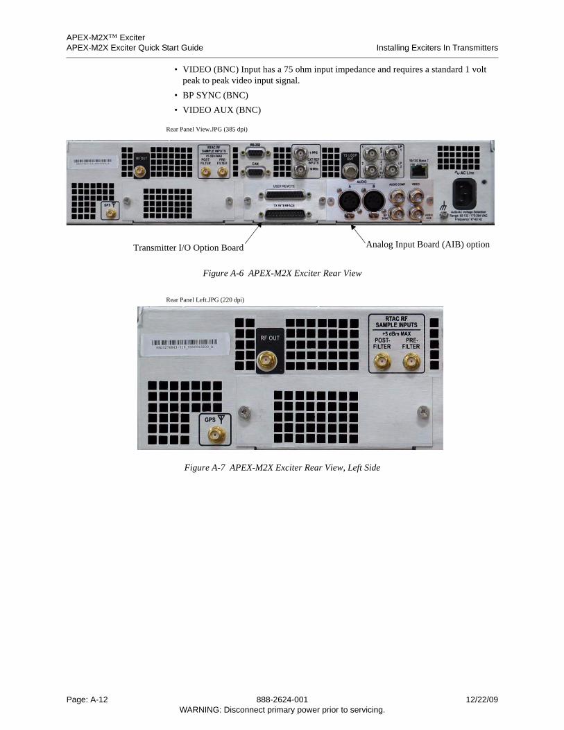
APEX-M2X™ ExciterAPEX-M2X Exciter Quick Start Guide Installing Exciters In Transmitters
• VIDEO (BNC) Input has a 75 ohm input impedance and requires a standard 1 volt peak to peak video input signal.
• BP SYNC (BNC)
• VIDEO AUX (BNC)
Rear Panel View.JPG (385 dpi)
Figure A-6 APEX-M2X Exciter Rear View
Rear Panel Left.JPG (220 dpi)
Figure A-7 APEX-M2X Exciter Rear View, Left Side
Transmitter I/O Option Board Analog Input Board (AIB) option
Page: A-12 888-2624-001 12/22/09WARNING: Disconnect primary power prior to servicing.
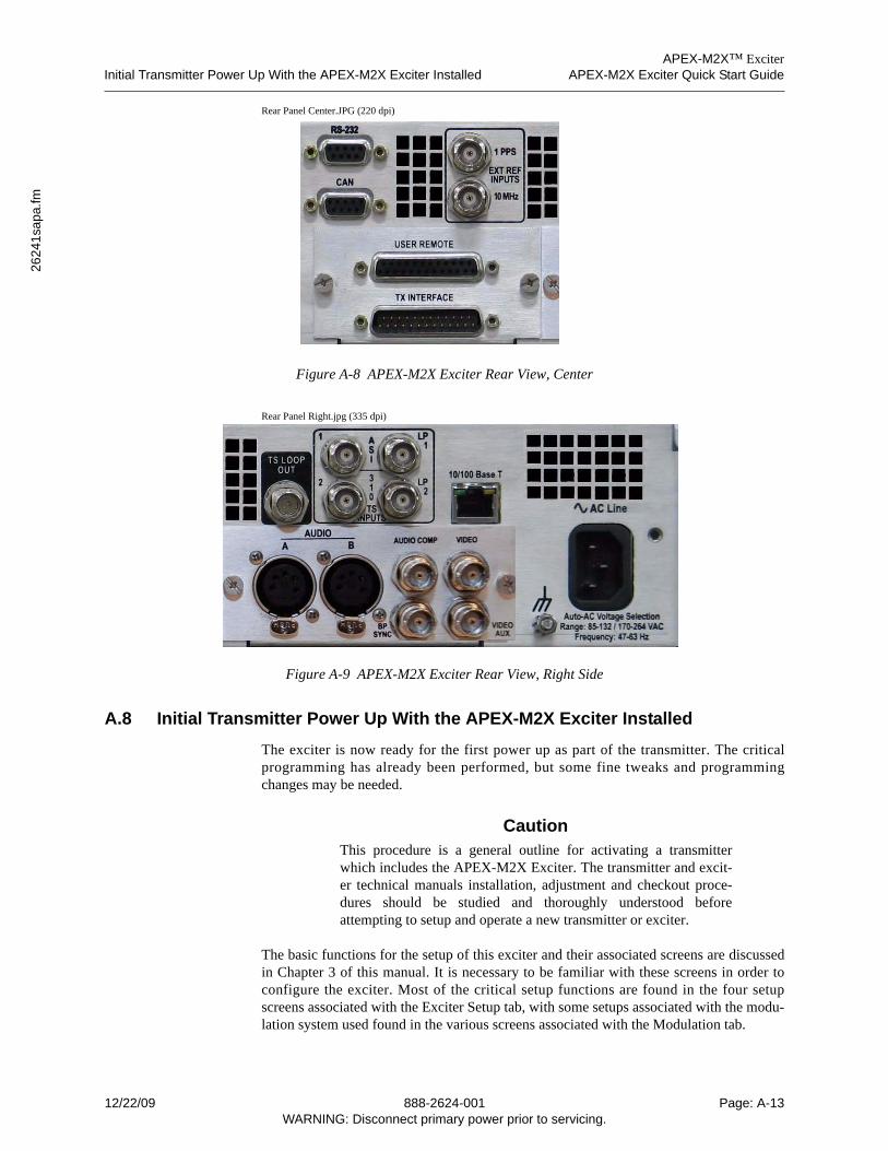
APEX-M2X™ ExciterInitial Transmitter Power Up With the APEX-M2X Exciter Installed APEX-M2X Exciter Quick Start Guide
2624
1sa
pa.fm
Rear Panel Center.JPG (220 dpi)
Figure A-8 APEX-M2X Exciter Rear View, Center
Rear Panel Right.jpg (335 dpi)
Figure A-9 APEX-M2X Exciter Rear View, Right Side
A.8 Initial Transmitter Power Up With the APEX-M2X Exciter Installed
The exciter is now ready for the first power up as part of the transmitter. The criticalprogramming has already been performed, but some fine tweaks and programmingchanges may be needed.
CautionThis procedure is a general outline for activating a transmitterwhich includes the APEX-M2X Exciter. The transmitter and excit-er technical manuals installation, adjustment and checkout proce-dures should be studied and thoroughly understood beforeattempting to setup and operate a new transmitter or exciter.
The basic functions for the setup of this exciter and their associated screens are discussedin Chapter 3 of this manual. It is necessary to be familiar with these screens in order toconfigure the exciter. Most of the critical setup functions are found in the four setupscreens associated with the Exciter Setup tab, with some setups associated with the modu-lation system used found in the various screens associated with the Modulation tab.
12/22/09 888-2624-001 Page: A-13WARNING: Disconnect primary power prior to servicing.

APEX-M2X™ ExciterAPEX-M2X Exciter Quick Start Guide Initial Transmitter Power Up With the APEX-M2X Exciter Installed
The initial transmitter power up is as follows.
1 Disconnect the pre and post filter RF sample lines at the exciter.
2 Energize the transmitter.
3 Set the output power to 100%.
A For a retrofit exciter, it is assumed that the transmitter had been functioning correctly with the old exciter and its output power is correctly calibrated.
B If the exciter has been shipped with a new transmitter, the exciter and trans-mitter have been set up in the factory and the only remaining tasks are the in-stallation checkout, minor system tweaks, power calibration, setting the exciter’s RTAC RF sample levels and the operational check remains.
4 Check the RF power level at the disconnected pre and post filter RF sample lines where they connect to the exciter.
A Use pads to set the level within the -20 to +5 dBm range for each cable
5 Connect the pre and post filter RF sample lines back to their connectors on the rear panel of the exciter.
6 In the exciter Home screen, set the Linear and Non-Linear RTAC functions to adapt
A It may take a few minutes for RTAC to adapt and correct the signal.
7 The engineer can now check the transmitter operation and record the data.
Some transmitters may experience nuisance overdrive trips which are caused by the Modu-lation peaks. These are caused by the modulation crest factor peaks and RTAC non-linearcorrection peak stretch capability. These two problems are corrected in the Exciter Setup >Adaptive Setup screen. Modulation crest factor peaks are limited by the “Max CrestFactor” value entered and RTAC non-linear correction peak stretch is limited by the“NonLinear Correction Range” value entered.
Page: A-14 888-2624-001 12/22/09WARNING: Disconnect primary power prior to servicing.
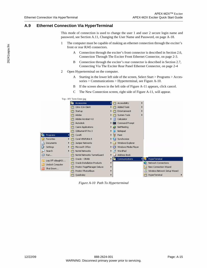
APEX-M2X™ ExciterEthernet Connection Via HyperTerminal APEX-M2X Exciter Quick Start Guide
2624
1sa
pa.fm
A.9 Ethernet Connection Via HyperTerminal
This mode of connection is used to change the user 1 and user 2 secure login name andpassword, see Section A.11, Changing the User Name and Password, on page A-18.
1 The computer must be capable of making an ethernet connection through the exciter’s front or rear RJ45 connectors.
A Connection through the exciter’s front connector is described in Section 2.6, Connection Through The Exciter Front Ethernet Connector, on page 2-3.
B Connection through the exciter’s rear connector is described in Section 2.7, Connecting Via The Exciter Rear Panel Ethernet Connector, on page 2-4
2 Open Hyperterminal on the computer.
A Starting in the lower left side of the screen, Select Start > Programs > Acces-sories > Communications > Hyperterminal, see Figure A-10.
B If the screen shown in the left side of Figure A-11 appears, click cancel.
C The New Connection screen, right side of Figure A-11, will appear.
Top - HY Term Enter.jpg
Figure A-10 Path To Hyperterminal
12/22/09 888-2624-001 Page: A-15WARNING: Disconnect primary power prior to servicing.

APEX-M2X™ ExciterAPEX-M2X Exciter Quick Start Guide Ethernet Connection Via HyperTerminal
HY Term New Connection.jpg (125)
Figure A-11 Hyperterminal New Connection Window
NoteIf a previous HyperTerminal connection has been saved, that con-nection can be recalled by pressing “File > Open” in the New Con-nection Window. A new window which displays previous savedconnections will open. Click the desired connection and press theopen soft key. That connection should be established.
3 In the New Connection screen select File > Properties.
A The New Connection Properties window will appear.
4 In the New Connection Properties window, click on Connect using drop down arrow.
5 Select TCP/IP (Winsock) from the drop down list.
6 Type in the desired exciter ethernet port address for the port being used (front or rear).
7 Select the Setting tab in the New Connection Properties window.
A The New Connection Properties Settings window, shown in Figure A-12, will open.
B Press the Emulation drop down arrow and select VT100.
C Configure the Settings widow like the one shown in Figure A-12.
D Press OK.
8 To save the configuration, press File > Save in the New Connection window.
A The Connection Description window, shown in Figure A-11, will appear.
B Click in the name box and type in a name, such as “Apex-M2X Telnet”.
C Press OK.
9 Connect by Clicking the phone icon or by using the menu selection “Call, Call.
10 When the connection is made, a window will appear with the words “Enter pass-word”. Type the User1 or User2 password and hit enter.
11 If the password is accepted, a screen like that shown in Figure A-13 will appear.
Page: A-16 888-2624-001 12/22/09WARNING: Disconnect primary power prior to servicing.
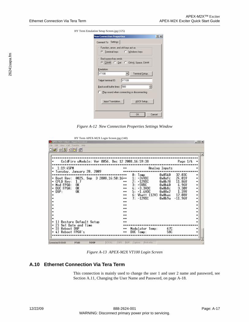
APEX-M2X™ ExciterEthernet Connection Via Tera Term APEX-M2X Exciter Quick Start Guide
2624
1sa
pa.fm
HY Term Emulation Setup Screen.jpg (125)
Figure A-12 New Connection Properties Settings Window
HY Term APEX-M2X Login Screen.jpg (140)
Figure A-13 APEX-M2X VT100 Login Screen
A.10 Ethernet Connection Via Tera Term
This connection is mainly used to change the user 1 and user 2 name and password, seeSection A.11, Changing the User Name and Password, on page A-18.
12/22/09 888-2624-001 Page: A-17WARNING: Disconnect primary power prior to servicing.
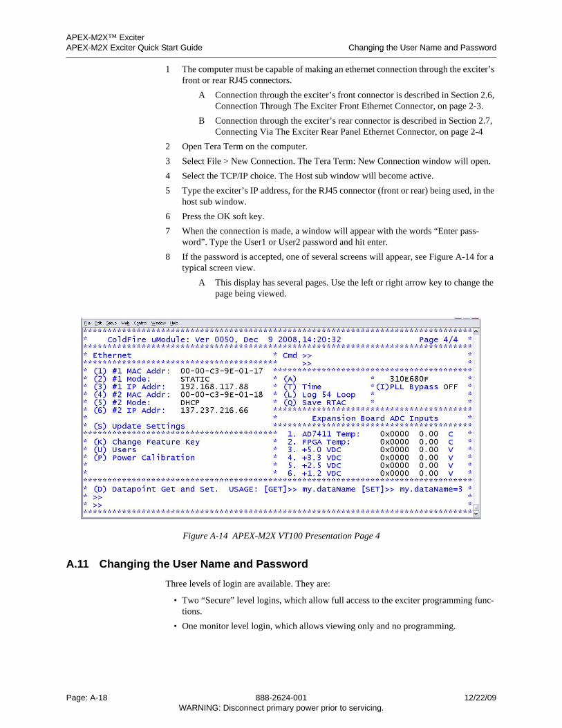
APEX-M2X™ ExciterAPEX-M2X Exciter Quick Start Guide Changing the User Name and Password
1 The computer must be capable of making an ethernet connection through the exciter’s front or rear RJ45 connectors.
A Connection through the exciter’s front connector is described in Section 2.6, Connection Through The Exciter Front Ethernet Connector, on page 2-3.
B Connection through the exciter’s rear connector is described in Section 2.7, Connecting Via The Exciter Rear Panel Ethernet Connector, on page 2-4
2 Open Tera Term on the computer.
3 Select File > New Connection. The Tera Term: New Connection window will open.
4 Select the TCP/IP choice. The Host sub window will become active.
5 Type the exciter’s IP address, for the RJ45 connector (front or rear) being used, in the host sub window.
6 Press the OK soft key.
7 When the connection is made, a window will appear with the words “Enter pass-word”. Type the User1 or User2 password and hit enter.
8 If the password is accepted, one of several screens will appear, see Figure A-14 for a typical screen view.
A This display has several pages. Use the left or right arrow key to change the page being viewed.
Figure A-14 APEX-M2X VT100 Presentation Page 4
A.11 Changing the User Name and Password
Three levels of login are available. They are:
• Two “Secure” level logins, which allow full access to the exciter programming func-tions.
• One monitor level login, which allows viewing only and no programming.
Page: A-18 888-2624-001 12/22/09WARNING: Disconnect primary power prior to servicing.
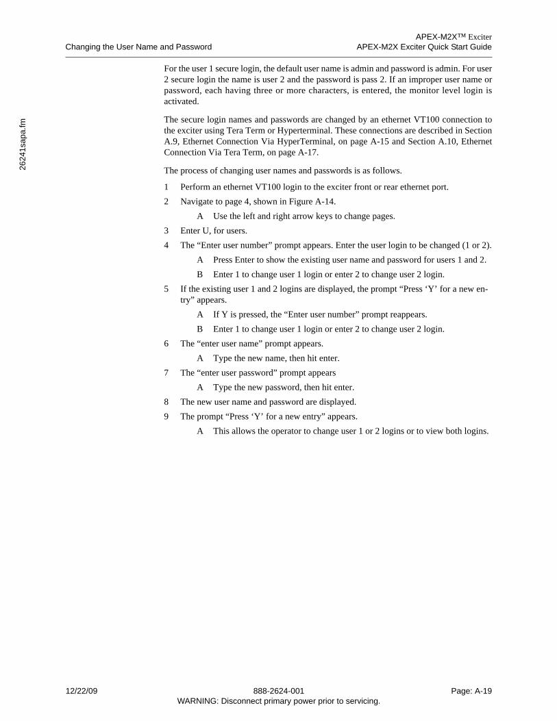
APEX-M2X™ ExciterChanging the User Name and Password APEX-M2X Exciter Quick Start Guide
2624
1sa
pa.fm
For the user 1 secure login, the default user name is admin and password is admin. For user2 secure login the name is user 2 and the password is pass 2. If an improper user name orpassword, each having three or more characters, is entered, the monitor level login isactivated.
The secure login names and passwords are changed by an ethernet VT100 connection tothe exciter using Tera Term or Hyperterminal. These connections are described in SectionA.9, Ethernet Connection Via HyperTerminal, on page A-15 and Section A.10, EthernetConnection Via Tera Term, on page A-17.
The process of changing user names and passwords is as follows.
1 Perform an ethernet VT100 login to the exciter front or rear ethernet port.
2 Navigate to page 4, shown in Figure A-14.
A Use the left and right arrow keys to change pages.
3 Enter U, for users.
4 The “Enter user number” prompt appears. Enter the user login to be changed (1 or 2).
A Press Enter to show the existing user name and password for users 1 and 2.
B Enter 1 to change user 1 login or enter 2 to change user 2 login.
5 If the existing user 1 and 2 logins are displayed, the prompt “Press ‘Y’ for a new en-try” appears.
A If Y is pressed, the “Enter user number” prompt reappears.
B Enter 1 to change user 1 login or enter 2 to change user 2 login.
6 The “enter user name” prompt appears.
A Type the new name, then hit enter.
7 The “enter user password” prompt appears
A Type the new password, then hit enter.
8 The new user name and password are displayed.
9 The prompt “Press ‘Y’ for a new entry” appears.
A This allows the operator to change user 1 or 2 logins or to view both logins.
12/22/09 888-2624-001 Page: A-19WARNING: Disconnect primary power prior to servicing.

APEX-M2X™ ExciterAPEX-M2X Exciter Quick Start Guide Changing the User Name and Password
Page: A-20 888-2624-001 12/22/09WARNING: Disconnect primary power prior to servicing.
APEX-M2X™ ExciterIntroduction APEX-M2X Exciter Installation
2624
1sa
pb.fm
Appendix B APEX-M2X Exciter Installation
B.1 Introduction
Exciters sold as part of a transmitter will normally have been tested in the transmitterbefore shipment. The exciter may be removed for shipment, to be reinstalled after the trans-mitter is in place. Installation is a simple process, as described in Section B.3 below.
Exciters sold for use in test facilities can either be rack mounted or operated sitting on awork surface.
Exciters sold for retrofit into existing transmitter systems will not only require mountingand appropriate mounting hardware, but this exciter also requires two RF Output samples.
When retrofit into an existing transmitter, the APEX-M2X exciter on site checkout needsto be done in two parts.
• First it is necessary to bench test the exciter in order to verify its RF frequency, set its RF output power, and set the other more critical parameters.
• Next, it is installed in the transmitter to complete the exciter setup and monitor its per-formance.
B.2 Retrofit Kits For APEX-M2X Exciters
The following three parts of this section list retrofit kits for replacing the CD-1A excitersor Classic APEX exciters with APEX-M2X exciters. If the APEX-M2X exciter is to beinstalled in another brand of transmitter, a custom retrofit kit will be required.
B.2.1 CD-1A to APEX-M2X Exciter Retrofits
The following kits are required if retrofitting APEX-M2X exciters in place of one or twoCD-1A exciters. These kits provide the materials necessary to retrofit two exciters, and areneeded if both are CD-1A exciters or if the transmitter contains only one exciter (a CD-1A)and a space for a second CD-1A. The kit numbers are as follows.
• 971-0061-001, Field Upgrade Kit, APEX-M2X Exciter Into Platinum Tx.Note: This upgrade does not apply to the Platinum I control cabinet, the Platinum I control cabinet was never fitted with CD-1A exciters.
• 971-0061-002, Field Upgrade Kit, APEX-M2X Exciter Into Diamond or Sigma Tx.
B.2.2 APEX-M2X Exciter Retrofit in a Ranger Transmitter
The exciter retrofit kit for a ranger transmitter is:
971-0061-005, Field Upgrade Kit, APEX-M2X Exciter Into Ranger Tx.
This kit is good when upgrading from either a CD-1A or Classic Apex exciter.
B.2.3 Classic APEX to APEX-M2X Exciter Retrofits
These kits are intended to provide the materials to retrofit one APEX-M2X exciter in placeof one Classic APEX exciter. If two exciters are to be retrofitted, two kits will be needed.
12/22/09 888-2624-001 Page: B-1WARNING: Disconnect primary power prior to servicing.
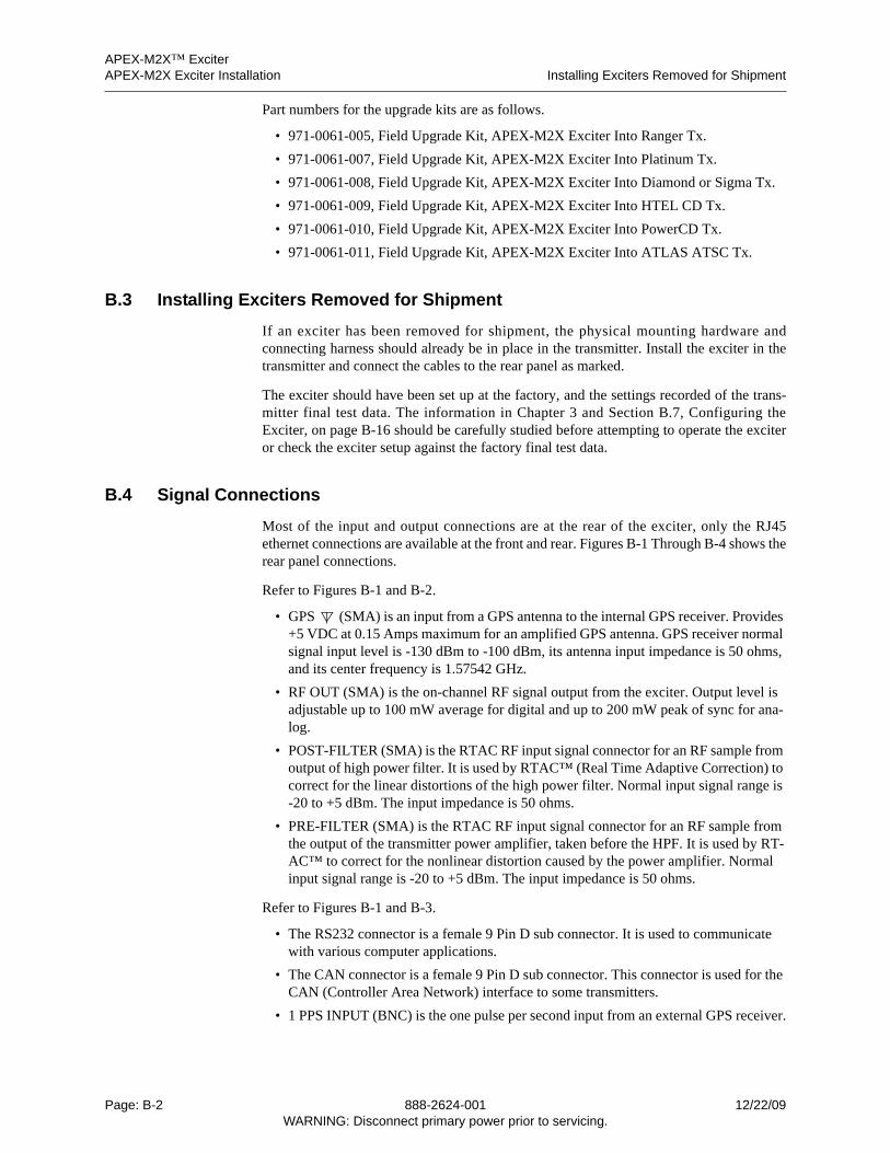
APEX-M2X™ ExciterAPEX-M2X Exciter Installation Installing Exciters Removed for Shipment
Part numbers for the upgrade kits are as follows.
• 971-0061-005, Field Upgrade Kit, APEX-M2X Exciter Into Ranger Tx.
• 971-0061-007, Field Upgrade Kit, APEX-M2X Exciter Into Platinum Tx.
• 971-0061-008, Field Upgrade Kit, APEX-M2X Exciter Into Diamond or Sigma Tx.
• 971-0061-009, Field Upgrade Kit, APEX-M2X Exciter Into HTEL CD Tx.
• 971-0061-010, Field Upgrade Kit, APEX-M2X Exciter Into PowerCD Tx.
• 971-0061-011, Field Upgrade Kit, APEX-M2X Exciter Into ATLAS ATSC Tx.
B.3 Installing Exciters Removed for Shipment
If an exciter has been removed for shipment, the physical mounting hardware andconnecting harness should already be in place in the transmitter. Install the exciter in thetransmitter and connect the cables to the rear panel as marked.
The exciter should have been set up at the factory, and the settings recorded of the trans-mitter final test data. The information in Chapter 3 and Section B.7, Configuring theExciter, on page B-16 should be carefully studied before attempting to operate the exciteror check the exciter setup against the factory final test data.
B.4 Signal Connections
Most of the input and output connections are at the rear of the exciter, only the RJ45ethernet connections are available at the front and rear. Figures B-1 Through B-4 shows therear panel connections.
Refer to Figures B-1 and B-2.
• GPS (SMA) is an input from a GPS antenna to the internal GPS receiver. Provides +5 VDC at 0.15 Amps maximum for an amplified GPS antenna. GPS receiver normal signal input level is -130 dBm to -100 dBm, its antenna input impedance is 50 ohms, and its center frequency is 1.57542 GHz.
• RF OUT (SMA) is the on-channel RF signal output from the exciter. Output level is adjustable up to 100 mW average for digital and up to 200 mW peak of sync for ana-log.
• POST-FILTER (SMA) is the RTAC RF input signal connector for an RF sample from output of high power filter. It is used by RTAC™ (Real Time Adaptive Correction) to correct for the linear distortions of the high power filter. Normal input signal range is -20 to +5 dBm. The input impedance is 50 ohms.
• PRE-FILTER (SMA) is the RTAC RF input signal connector for an RF sample from the output of the transmitter power amplifier, taken before the HPF. It is used by RT-AC™ to correct for the nonlinear distortion caused by the power amplifier. Normal input signal range is -20 to +5 dBm. The input impedance is 50 ohms.
Refer to Figures B-1 and B-3.
• The RS232 connector is a female 9 Pin D sub connector. It is used to communicate with various computer applications.
• The CAN connector is a female 9 Pin D sub connector. This connector is used for the CAN (Controller Area Network) interface to some transmitters.
• 1 PPS INPUT (BNC) is the one pulse per second input from an external GPS receiver.
Page: B-2 888-2624-001 12/22/09WARNING: Disconnect primary power prior to servicing.
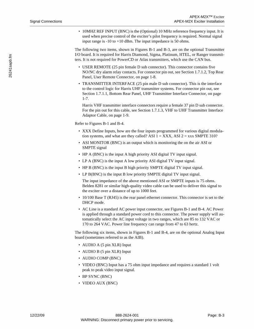
APEX-M2X™ ExciterSignal Connections APEX-M2X Exciter Installation
2624
1sa
pb.fm
• 10MHZ REF INPUT (BNC) is the (Optional) 10 MHz reference frequency input. It is used when precise control of the exciter’s pilot frequency is required. Normal signal input range is -10 to +10 dBm. The input impedance is 50 ohms.
The following two items, shown in Figures B-1 and B-3, are on the optional TransmitterI/O board. It is required for Harris Diamond, Sigma, Platinum, HTEL, or Ranger transmit-ters. It is not required for PowerCD or Atlas transmitters, which use the CAN bus.
• USER REMOTE (25 pin female D sub connector). This connector contains five NO/NC dry alarm relay contacts. For connector pin out, see Section 1.7.1.2, Top Rear Panel, User Remote Connector, on page 1-8.
• TRANSMITTER INTERFACE (25 pin male D sub connector). This is the interface to the control logic for Harris UHF transmitter systems. For connector pin out, see Section 1.7.1.1, Bottom Rear Panel, UHF Transmitter Interface Connector, on page 1-7.
Harris VHF transmitter interface connectors require a female 37 pin D sub connector. For the pin out for this cable, see Section 1.7.1.3, VHF to UHF Transmitter Interface Adaptor Cable, on page 1-9.
Refer to Figures B-1 and B-4.
• XXX Define Inputs, how are the four inputs programmed for various digital modula-tion systems, and what are they called? ASI 1 = XXX, ASI 2 = xxx SMPTE 310?
• ASI MONITOR (BNC) is an output which is monitoring the on the air ASI or SMPTE signal
• HP A (BNC) is the input A high priority ASI digital TV input signal.
• LP A (BNC) is the input A low priority ASI digital TV input signal.
• HP B (BNC) is the input B high priority SMPTE digital TV input signal.
• LP B(BNC) is the input B low priority SMPTE digital TV input signal.
The input impedance of the above mentioned ASI or SMPTE inputs is 75 ohms. Belden 8281 or similar high-quality video cable can be used to deliver this signal to the exciter over a distance of up to 1000 feet.
• 10/100 Base T (RJ45) is the rear panel ethernet connector. This connector is set to the DHCP mode.
• AC Line is a standard AC power input connector, see Figures B-1 and B-4. AC Power is applied through a standard power cord to this connector. The power supply will au-tomatically select the AC input voltage in two ranges, which are 85 to 132 VAC or 170 to 264 VAC. Power line frequency can range from 47 to 63 hertz.
The following six items, shown in Figures B-1 and B-4, are on the optional Analog Inputboard (sometimes referred to as the AIB).
• AUDIO A (5 pin XLR) Input
• AUDIO B (5 pin XLR) Input
• AUDIO COMP (BNC)
• VIDEO (BNC) Input has a 75 ohm input impedance and requires a standard 1 volt peak to peak video input signal.
• BP SYNC (BNC)
• VIDEO AUX (BNC)
12/22/09 888-2624-001 Page: B-3WARNING: Disconnect primary power prior to servicing.
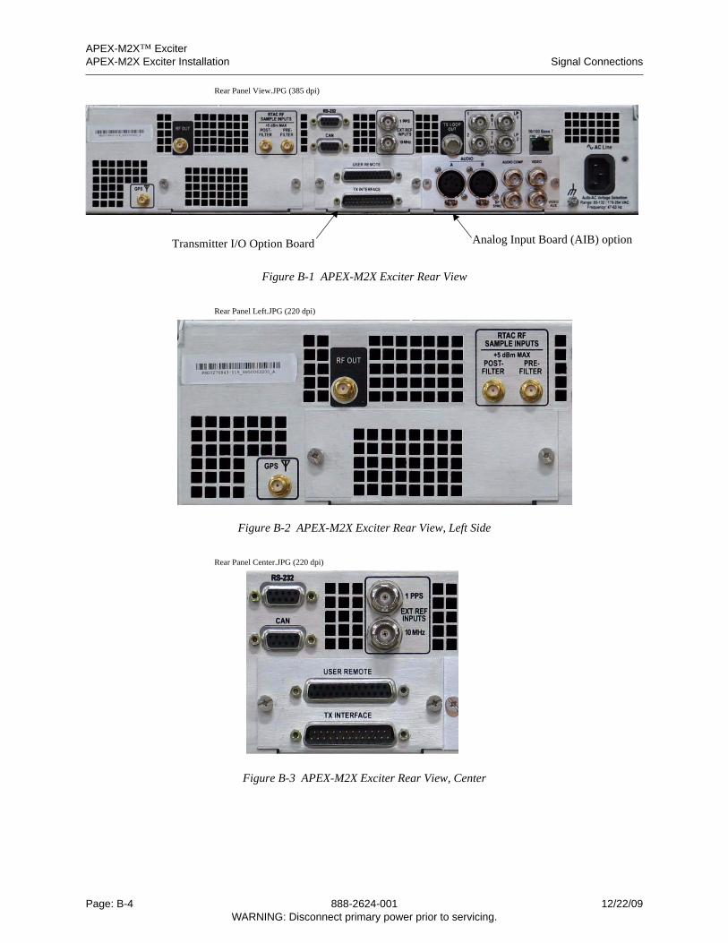
APEX-M2X™ ExciterAPEX-M2X Exciter Installation Signal Connections
Rear Panel View.JPG (385 dpi)
Figure B-1 APEX-M2X Exciter Rear View
Rear Panel Left.JPG (220 dpi)
Figure B-2 APEX-M2X Exciter Rear View, Left Side
Rear Panel Center.JPG (220 dpi)
Figure B-3 APEX-M2X Exciter Rear View, Center
Transmitter I/O Option Board Analog Input Board (AIB) option
Page: B-4 888-2624-001 12/22/09WARNING: Disconnect primary power prior to servicing.
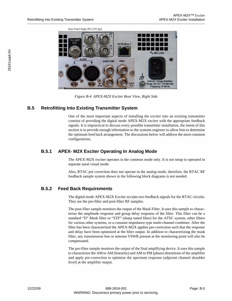
APEX-M2X™ ExciterRetrofitting Into Existing Transmitter System APEX-M2X Exciter Installation
2624
1sa
pb.fm
Rear Panel Right.JPG (335 dpi)
Figure B-4 APEX-M2X Exciter Rear View, Right Side
B.5 Retrofitting Into Existing Transmitter System
One of the most important aspects of installing the exciter into an existing transmitterconsists of providing the digital mode APEX-M2X exciter with the appropriate feedbacksignals. It is impractical to discuss every possible transmitter installation, the intent of thissection is to provide enough information to the systems engineer to allow him to determinethe optimum feed back arrangement. The discussions below will address the most commonconfigurations.
B.5.1 APEX- M2X Exciter Operating In Analog Mode
The APEX-M2X exciter operates in the common mode only. It is not setup to operated inseparate aural visual mode.
Also, RTAC pre correction does not operate in the analog mode, therefore, the RTAC RFfeedback sample system shown in the following block diagrams is not needed.
B.5.2 Feed Back Requirements
The digital mode APEX-M2X Exciter accepts two feedback signals for the RTAC circuits.They are the pre-filter and post-filter RF samples.
The post-filter sample monitors the output of the Mask Filter. It uses this sample to charac-terize the amplitude response and group delay response of the filter. This filter can be astandard “D” Mask filter or “STF” (sharp tuned filter) for the ATSC system, other filtersfor various other systems, or a constant impedance type multi-channel combiner. After thefilter has been characterized the APEX-M2X applies pre-correction such that the responseand delay have been optimized at the filter output. In addition to characterizing the maskfilter, any transmission line or antenna VSWR present at the monitoring point will also becompensated.
The pre-filter sample monitors the output of the final amplifying device. It uses this sampleto characterize the AM to AM (linearity) and AM to PM (phase) distortions of the amplifierand apply pre-correction to optimize the spectrum response (adjacent channel shoulderlevel) at the amplifier output.
12/22/09 888-2624-001 Page: B-5WARNING: Disconnect primary power prior to servicing.
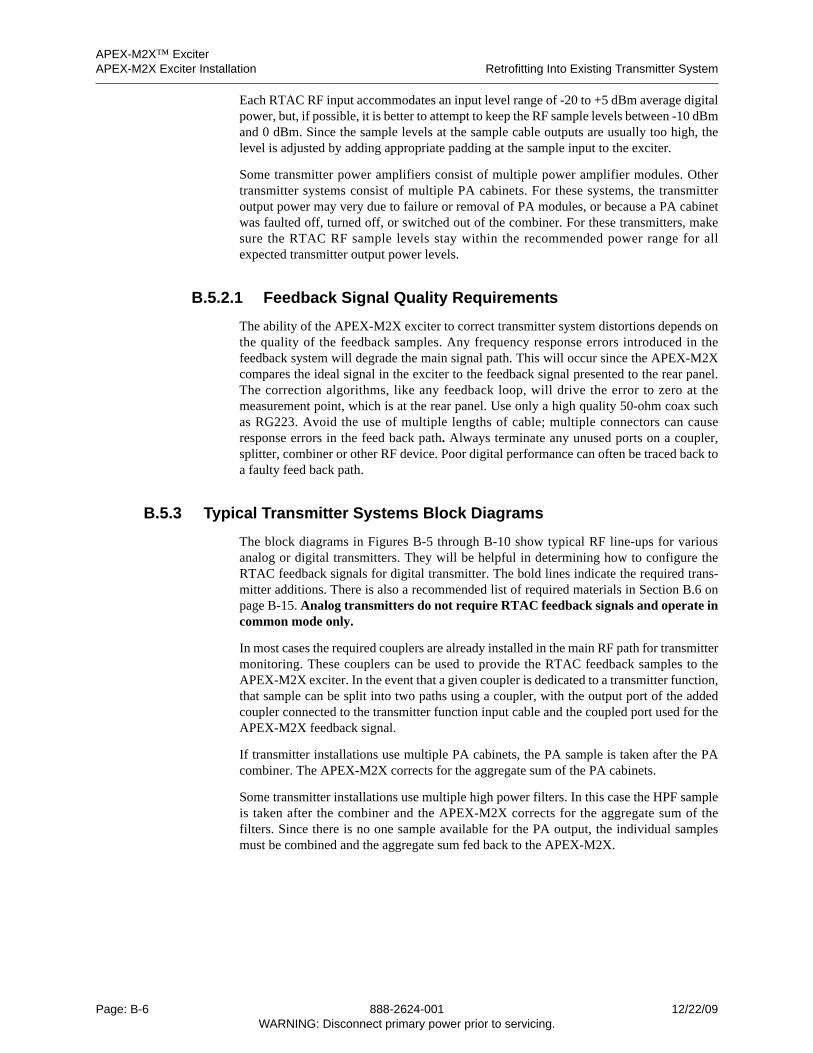
APEX-M2X™ ExciterAPEX-M2X Exciter Installation Retrofitting Into Existing Transmitter System
Each RTAC RF input accommodates an input level range of -20 to +5 dBm average digitalpower, but, if possible, it is better to attempt to keep the RF sample levels between -10 dBmand 0 dBm. Since the sample levels at the sample cable outputs are usually too high, thelevel is adjusted by adding appropriate padding at the sample input to the exciter.
Some transmitter power amplifiers consist of multiple power amplifier modules. Othertransmitter systems consist of multiple PA cabinets. For these systems, the transmitteroutput power may very due to failure or removal of PA modules, or because a PA cabinetwas faulted off, turned off, or switched out of the combiner. For these transmitters, makesure the RTAC RF sample levels stay within the recommended power range for allexpected transmitter output power levels.
B.5.2.1 Feedback Signal Quality Requirements
The ability of the APEX-M2X exciter to correct transmitter system distortions depends onthe quality of the feedback samples. Any frequency response errors introduced in thefeedback system will degrade the main signal path. This will occur since the APEX-M2Xcompares the ideal signal in the exciter to the feedback signal presented to the rear panel.The correction algorithms, like any feedback loop, will drive the error to zero at themeasurement point, which is at the rear panel. Use only a high quality 50-ohm coax suchas RG223. Avoid the use of multiple lengths of cable; multiple connectors can causeresponse errors in the feed back path. Always terminate any unused ports on a coupler,splitter, combiner or other RF device. Poor digital performance can often be traced back toa faulty feed back path.
B.5.3 Typical Transmitter Systems Block Diagrams
The block diagrams in Figures B-5 through B-10 show typical RF line-ups for variousanalog or digital transmitters. They will be helpful in determining how to configure theRTAC feedback signals for digital transmitter. The bold lines indicate the required trans-mitter additions. There is also a recommended list of required materials in Section B.6 onpage B-15. Analog transmitters do not require RTAC feedback signals and operate incommon mode only.
In most cases the required couplers are already installed in the main RF path for transmittermonitoring. These couplers can be used to provide the RTAC feedback samples to theAPEX-M2X exciter. In the event that a given coupler is dedicated to a transmitter function,that sample can be split into two paths using a coupler, with the output port of the addedcoupler connected to the transmitter function input cable and the coupled port used for theAPEX-M2X feedback signal.
If transmitter installations use multiple PA cabinets, the PA sample is taken after the PAcombiner. The APEX-M2X corrects for the aggregate sum of the PA cabinets.
Some transmitter installations use multiple high power filters. In this case the HPF sampleis taken after the combiner and the APEX-M2X corrects for the aggregate sum of thefilters. Since there is no one sample available for the PA output, the individual samplesmust be combined and the aggregate sum fed back to the APEX-M2X.
Page: B-6 888-2624-001 12/22/09WARNING: Disconnect primary power prior to servicing.
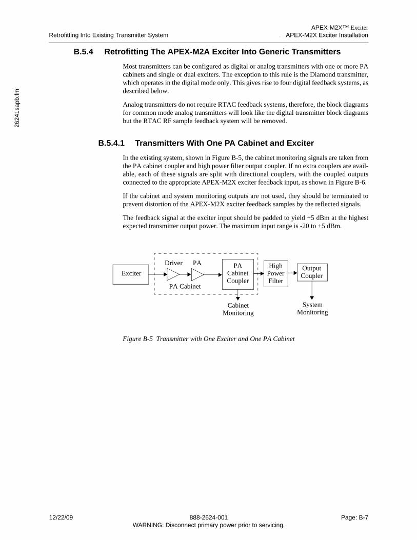
APEX-M2X™ ExciterRetrofitting Into Existing Transmitter System APEX-M2X Exciter Installation
2624
1sa
pb.fm
B.5.4 Retrofitting The APEX-M2A Exciter Into Generic Transmitters
Most transmitters can be configured as digital or analog transmitters with one or more PAcabinets and single or dual exciters. The exception to this rule is the Diamond transmitter,which operates in the digital mode only. This gives rise to four digital feedback systems, asdescribed below.
Analog transmitters do not require RTAC feedback systems, therefore, the block diagramsfor common mode analog transmitters will look like the digital transmitter block diagramsbut the RTAC RF sample feedback system will be removed.
B.5.4.1 Transmitters With One PA Cabinet and Exciter
In the existing system, shown in Figure B-5, the cabinet monitoring signals are taken fromthe PA cabinet coupler and high power filter output coupler. If no extra couplers are avail-able, each of these signals are split with directional couplers, with the coupled outputsconnected to the appropriate APEX-M2X exciter feedback input, as shown in Figure B-6.
If the cabinet and system monitoring outputs are not used, they should be terminated toprevent distortion of the APEX-M2X exciter feedback samples by the reflected signals.
The feedback signal at the exciter input should be padded to yield +5 dBm at the highestexpected transmitter output power. The maximum input range is -20 to +5 dBm.
Figure B-5 Transmitter with One Exciter and One PA Cabinet
OutputCoupler
HighPower
PACabinet
Filter
SystemMonitoring
CabinetMonitoring
CouplerExciter
PADriver
PA Cabinet
12/22/09 888-2624-001 Page: B-7WARNING: Disconnect primary power prior to servicing.
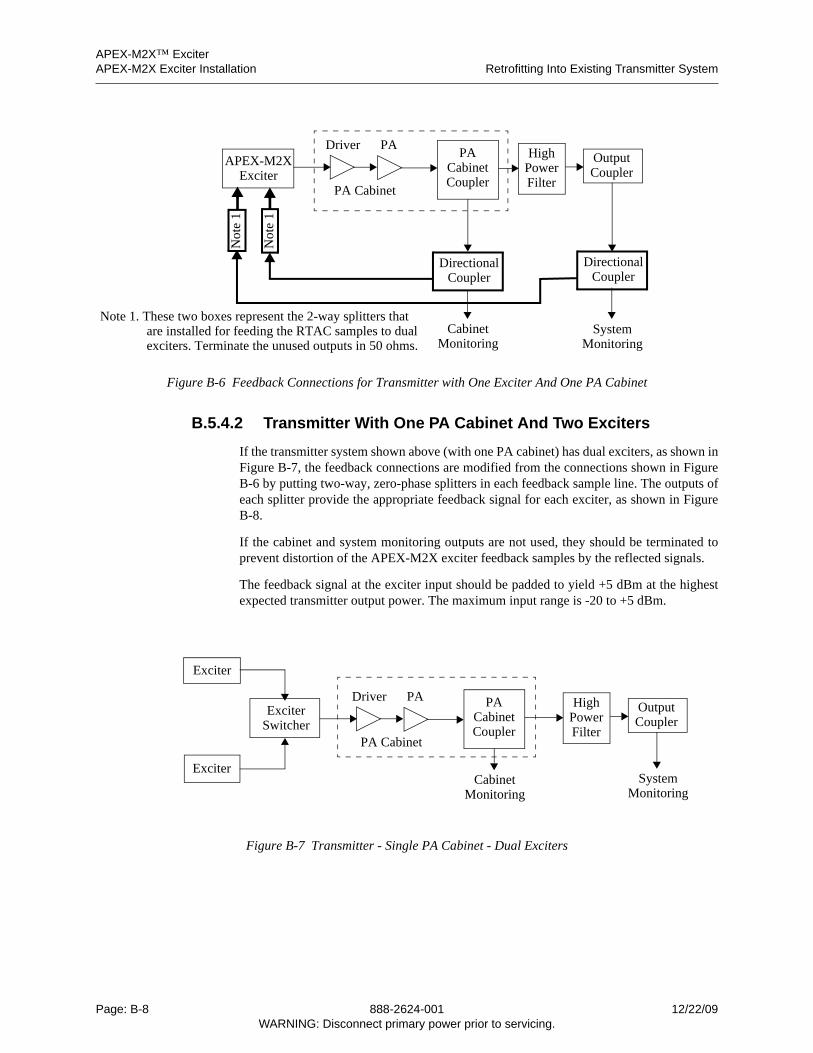
APEX-M2X™ ExciterAPEX-M2X Exciter Installation Retrofitting Into Existing Transmitter System
Figure B-6 Feedback Connections for Transmitter with One Exciter And One PA Cabinet
B.5.4.2 Transmitter With One PA Cabinet And Two Exciters
If the transmitter system shown above (with one PA cabinet) has dual exciters, as shown inFigure B-7, the feedback connections are modified from the connections shown in FigureB-6 by putting two-way, zero-phase splitters in each feedback sample line. The outputs ofeach splitter provide the appropriate feedback signal for each exciter, as shown in FigureB-8.
If the cabinet and system monitoring outputs are not used, they should be terminated toprevent distortion of the APEX-M2X exciter feedback samples by the reflected signals.
The feedback signal at the exciter input should be padded to yield +5 dBm at the highestexpected transmitter output power. The maximum input range is -20 to +5 dBm.
Figure B-7 Transmitter - Single PA Cabinet - Dual Exciters
PAOutputCoupler
HighPower
PACabinet
FilterCoupler
APEX-M2XExciter
DirectionalCoupler
CabinetMonitoring
DirectionalCoupler
SystemMonitoring
Driver
Not
e 1
Not
e 1
Note 1. These two boxes represent the 2-way splitters thatare installed for feeding the RTAC samples to dualexciters. Terminate the unused outputs in 50 ohms.
PA Cabinet
OutputCoupler
HighPower
PACabinetExciter
Filter
SystemMonitoring
CabinetMonitoring
Switcher Coupler
Exciter
Exciter
PADriver
PA Cabinet
Page: B-8 888-2624-001 12/22/09WARNING: Disconnect primary power prior to servicing.
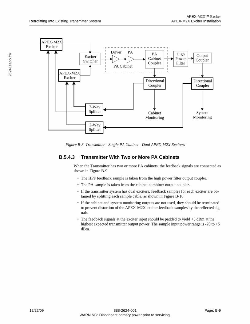
APEX-M2X™ ExciterRetrofitting Into Existing Transmitter System APEX-M2X Exciter Installation
2624
1sa
pb.fm
Figure B-8 Transmitter - Single PA Cabinet - Dual APEX-M2X Exciters
B.5.4.3 Transmitter With Two or More PA Cabinets
When the Transmitter has two or more PA cabinets, the feedback signals are connected asshown in Figure B-9.
• The HPF feedback sample is taken from the high power filter output coupler.
• The PA sample is taken from the cabinet combiner output coupler.
• If the transmitter system has dual exciters, feedback samples for each exciter are ob-tained by splitting each sample cable, as shown in Figure B-10
• If the cabinet and system monitoring outputs are not used, they should be terminated to prevent distortion of the APEX-M2X exciter feedback samples by the reflected sig-nals.
• The feedback signals at the exciter input should be padded to yield +5 dBm at the highest expected transmitter output power. The sample input power range is -20 to +5 dBm.
OutputCoupler
HighPower
PACabinetExciter
FilterSwitcher Coupler
APEX-M2XExciter
APEX-M2XExciter
DirectionalCoupler
CabinetMonitoring
DirectionalCoupler
SystemMonitoring
2-WaySplitter
2-WaySplitter
PADriver
PA Cabinet
12/22/09 888-2624-001 Page: B-9WARNING: Disconnect primary power prior to servicing.
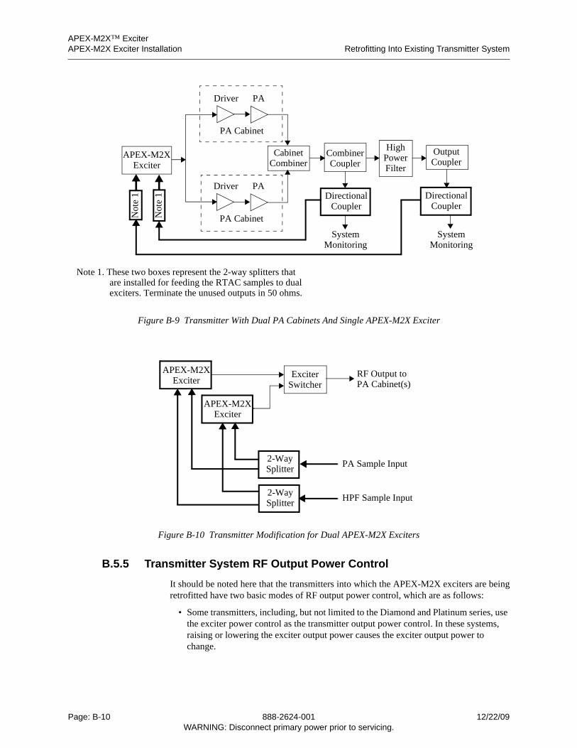
APEX-M2X™ ExciterAPEX-M2X Exciter Installation Retrofitting Into Existing Transmitter System
Figure B-9 Transmitter With Dual PA Cabinets And Single APEX-M2X Exciter
Figure B-10 Transmitter Modification for Dual APEX-M2X Exciters
B.5.5 Transmitter System RF Output Power Control
It should be noted here that the transmitters into which the APEX-M2X exciters are beingretrofitted have two basic modes of RF output power control, which are as follows:
• Some transmitters, including, but not limited to the Diamond and Platinum series, use the exciter power control as the transmitter output power control. In these systems, raising or lowering the exciter output power causes the exciter output power to change.
OutputCoupler
HighPowerCombiner
CouplerCabinet
Combiner
DirectionalCoupler
DirectionalCoupler
Filter
SystemMonitoring
SystemMonitoring
APEX-M2XExciter
PADriver
PA Cabinet
PADriver
PA CabinetNot
e 1
Not
e 1
Note 1. These two boxes represent the 2-way splitters thatare installed for feeding the RTAC samples to dualexciters. Terminate the unused outputs in 50 ohms.
ExciterSwitcher
APEX-M2XExciter
APEX-M2XExciter
2-WaySplitter
2-WaySplitter
RF Output toPA Cabinet(s)
PA Sample Input
HPF Sample Input
Page: B-10 888-2624-001 12/22/09WARNING: Disconnect primary power prior to servicing.

APEX-M2X™ ExciterRetrofitting Into Existing Transmitter System APEX-M2X Exciter Installation
2624
1sa
pb.fm
• Some transmitters, including, but not limited to the Sigma and PowerCD series, re-quire a fixed output power from the exciter, with the power control circuitry located after the exciter switcher output.
Since this exciter will be retrofitted into a variety of transmitters, the installation engineershould be familiar with transmitter and exciter control systems.
B.5.6 Diamond Transmitters
Diamond transmitters can be configured as digital transmitters with one or more PAcabinets and single or dual exciters. The main difference between the Diamond transmit-ters and other transmitter models is that the Diamond transmitter has a driver associatedwith each exciter, as shown in Figure B-11. For these transmitters, the exciter switcher islocated after the drivers.
The Diamond configuration places the driver module in the control cabinet. The driveroutput feeds one to five PA cabinets. If the transmitter system has dual exciters and drivers,the driver outputs are connected to a coax relay, which connects one exciter driver pair toa test load and the other exciter driver pair to drive the PA cabinets.
Note: If the Diamond transmitter has one PA cabinet with four PA modules, it will have nodriver module. The exciter output will drive the PA module splitter in the PA cabinetdirectly.
Figure B-11 Diamond Transmitter - Dual PA Cabinets and Dual APEX-M2X Exciters
PA
PA
OutputCoupler
HighPowerCombiner
CouplerCabinet
Combiner Filter
ExciterSwitcher
APEX-M2XExciter
APEX-M2XExciter
2-WaySplitter
2-WaySplitter
Driver
Driver
SystemMonitoring
SystemMonitoring
PA Cabinet
PA Cabinet
12/22/09 888-2624-001 Page: B-11WARNING: Disconnect primary power prior to servicing.
APEX-M2X™ ExciterAPEX-M2X Exciter Installation Retrofitting Into Existing Transmitter System
B.5.7 Sigma Transmitters
Sigma transmitters can be configured with one or more PA cabinets and single or dualexciters. Multiple PA cabinet systems can be configured with multiple high power filters.When retrofitting an APEX-M2X exciter into any Sigma transmitter, some of the uniquefeatures of the various Sigma transmitter models must be taken into account.
Sigma transmitters have several IPA (IOT driver) systems, which include the following:
• Early Sigmas had the Bipolar IPA and No Feed forward system.
• Later Sigmas had the Bipolar IPA and the IPA Feed forward system.
• These two above mentioned systems included the RF Corrector module, which con-tains the PA automatic power control and the PA linearization circuits.
• Some of these Sigma models had their RF correctors replaced with AGC/UHF linearization modules. These modules provided improved per-formance over the RF correctors, but performed the same functions.
• Later Sigmas with Bipolar IPAs with Feed Forward were all shipped with AGC/UHF linearization modules.
• If only the APEX-M2X exciters are being used in the above mentioned Sigmas, the RF corrector or AGC/UHF linearizer must be retained be-cause of its automatic power control function, but the correction should be switched out or adjusted to be transparent.
• The current generations of Sigma transmitters use the DHD Diamond IPA module.
These models have the SD1 chassis which functions as the transmitter automatic power control (APC) and has circuits used to linearize the Diamond IPA module.
These modules also have the UHF linearizer. It is connected before the SD1 module and serves to linearize the IOT.
• If the transmitter is to be digital and one of the two exciters is still the CD-1 or CD1-A, see Figure B-12, the UHF linearizer must remain active and both the UHF linearizer and the SD1 must be adjusted to correct the transmitter for the benefit of the CD exciter.
• If one or two APEX-M2X exciters are being used, see Figures B-13 and B-14, or if the two exciters consist of one APEX-M2X and the one origi-nal APEX exciter, see Figure B-14, the UHF linearizer can be removed and the SD1 will be the first module in the PA cabinet.
The RF corrector, AGC/UHF corrector, and the UHF corrector disposition has been dealtwith above. In all of the above Sigma transmitters, the feed forward system (for BipolarIPA Sigmas) or the SD1 chassis (for Diamond IPA Sigmas) must remain in the transmit-ters. They should be handled as follows:
• The feed forward system should be adjusted (with all exciter correction bypassed) to linearize the bipolar IPA.
• The SD1 must be adjusted to control the PA cabinet output power, and should also be adjusted to linearize the IPA.
Page: B-12 888-2624-001 12/22/09WARNING: Disconnect primary power prior to servicing.
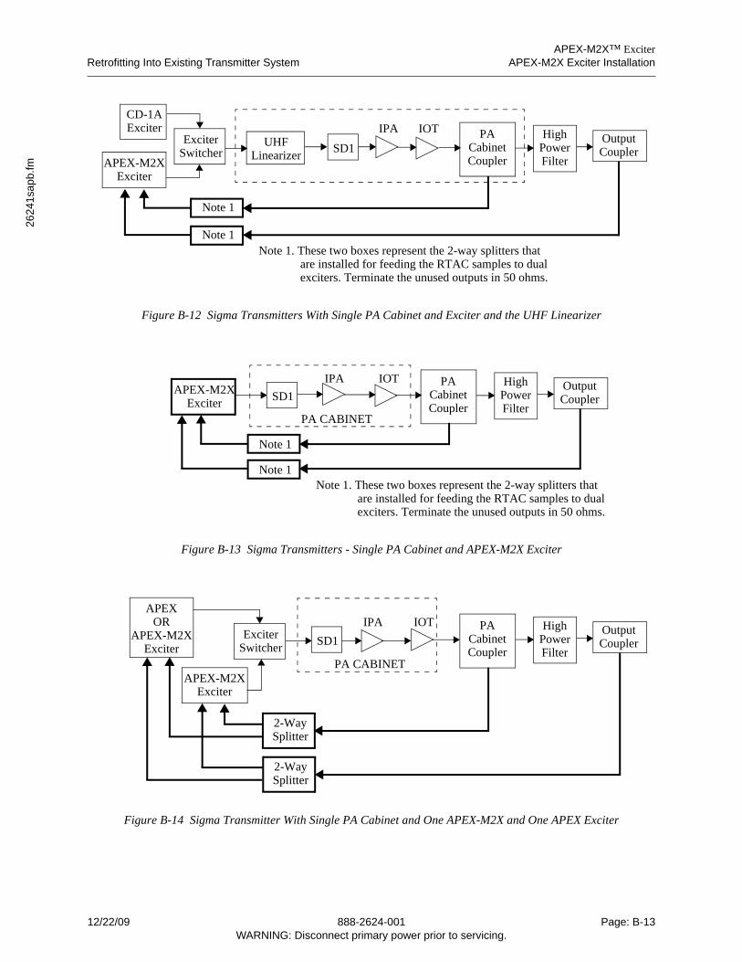
APEX-M2X™ ExciterRetrofitting Into Existing Transmitter System APEX-M2X Exciter Installation
2624
1sa
pb.fm
Figure B-12 Sigma Transmitters With Single PA Cabinet and Exciter and the UHF Linearizer
Figure B-13 Sigma Transmitters - Single PA Cabinet and APEX-M2X Exciter
Figure B-14 Sigma Transmitter With Single PA Cabinet and One APEX-M2X and One APEX Exciter
IOTIPAOutputCoupler
HighPower
PACabinet
Filter
CD-1A
CouplerSD1UHF
LinearizerAPEX-M2X
Exciter
Note 1
Note 1
ExciterSwitcher
Exciter
Note 1. These two boxes represent the 2-way splitters thatare installed for feeding the RTAC samples to dualexciters. Terminate the unused outputs in 50 ohms.
IOTIPAOutputCoupler
HighPower
PACabinet
FilterCoupler
APEX-M2XExciter
Note 1
Note 1Note 1. These two boxes represent the 2-way splitters that
are installed for feeding the RTAC samples to dualexciters. Terminate the unused outputs in 50 ohms.
SD1
PA CABINET
IOTIPAOutputCoupler
HighPower
PACabinet
FilterCoupler
ExciterSwitcher
APEX-M2XExciter
APEXOR
2-WaySplitter
2-WaySplitter
APEX-M2XExciter
PA CABINET
SD1
12/22/09 888-2624-001 Page: B-13WARNING: Disconnect primary power prior to servicing.
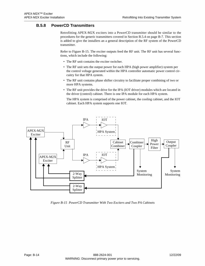
APEX-M2X™ ExciterAPEX-M2X Exciter Installation Retrofitting Into Existing Transmitter System
B.5.8 PowerCD Transmitters
Retrofitting APEX-M2X exciters into a PowerCD transmitter should be similar to theprocedures for the generic transmitters covered in Section B.5.4 on page B-7. This sectionis added to give the installers an a general description of the RF system of the PowerCDtransmitter.
Refer to Figure B-15. The exciter outputs feed the RF unit. The RF unit has several func-tions, which include the following:
• The RF unit contains the exciter switcher.
• The RF unit sets the output power for each HPA (high power amplifier) system per the control voltage generated within the HPA controller automatic power control cir-cuitry for that HPA system.
• The RF unit contains phase shifter circuitry to facilitate proper combining of two or more HPA systems.
• The RF unit provides the drive for the IPA (IOT driver) modules which are located in the driver (control) cabinet. There is one IPA module for each HPA system.
The HPA system is comprised of the power cabinet, the cooling cabinet, and the IOT cabinet. Each HPA system supports one IOT.
Figure B-15 PowerCD Transmitter With Two Exciters and Two PA Cabinets
IOT
OutputCoupler
HighPowerCombiner
CouplerCabinet
Combiner Filter
APEX-M2XExciter
APEX-M2XExciter
2-WaySplitter
2-WaySplitter
IPA
SystemMonitoring
SystemMonitoring
HPA System
IOT
HPA System
RFUnit
IPA
Page: B-14 888-2624-001 12/22/09WARNING: Disconnect primary power prior to servicing.
APEX-M2X™ ExciterTypical Materials Needed APEX-M2X Exciter Installation
2624
1sa
pb.fm
B.6 Typical Materials Needed
The following list represents the materials that may be used for the various field installs.Not all materials are required for every installation.
• Coupler, Mini Circuit, ZFDC-10-21, 50 ohm BNC, Harris part number 620-2969-000
This coupler is used when a spare sample is not available. It is place in line at the measurement point and the coupled port used for the feedback. The coupled port has a 10 dB attenuation from the input.
• Splitter, two port, Mini Circuits, ZFSC-2-2, zero phase, 50 ohm SMA, Harris part number 620-2964-000
This splitter is used to split the feed back signals to two exciters.
• Splitter, two port, Mini Circuits, ZFSC-2-2, zero phase, 50 ohm BNC, Harris part number 620-1563-000
This splitter is used to combine the PA feed back signal from two PA cabinets if sep-arate mask filters are used for each PA.
• Splitter, four port, Mini Circuits, ZFSC-4-1, zero phase, 50 ohm BNC, Harris part number 620-2833-000
This splitter is used to combine the PA feed back signal from three or four PA cabi-nets if separate mask filters are used for each PA. For combining samples from three PA cabinets, terminate unused input port.
• Adapters, N female to BNC male, Harris part number 620-0128-000
Used to connect a BNC coupler directly to the N connector on the RF system.
• Adapter, BNC female to N male, Harris part number 620-0547-000
Used to connect the original RF system cable to feedback coupler.
• Adapter, BNC male to BNC male, Harris part number 620-0564-000
Used in Platinum transmitters to connect the feedback coupler directly to the RF sam-ple coupler.
• Adapter TNC female to BNC male, Harris part number 620-2967-000
Used in Sigma to connect the feedback coupler directly to the breakaway couplers.
• Adapter, BNC female to TNC male, Harris part number 620-2821-000
Used in Sigma to connect original breakaway coupler cable to the feedback coupler.
• RF Cables, the number and type of each depends on transmitter type and installation. Depending on installation, other lengths and connector combinations may be needed.
30 ft, RG223, 50 ohm, BNC male to SMA male
30 ft, RG223, 50 ohm, BNC male to BNC male
30 ft, RG223, 50 ohm, N male to BNC male
30 ft, RG223, 50 ohm, N male to SMA male
30 ft, RG223, 50 ohm, N male to N male
10 ft, RG223, 50 ohm, BNC male to SMA male
3 ft, RG223, 50 ohm BNC to BNC
3 ft, RG223, 50 ohm BNC to SMA male
12/22/09 888-2624-001 Page: B-15WARNING: Disconnect primary power prior to servicing.
APEX-M2X™ ExciterAPEX-M2X Exciter Installation Configuring the Exciter
B.7 Configuring the Exciter
Refer to Appendix A, APEX-M2X Exciter Quick Start Guide for the first bench testpowerup of the APEX-M2X exciter and then its subsequent installation into thetransmitter.
Page: B-16 888-2624-001 12/22/09WARNING: Disconnect primary power prior to servicing.