Embed Size (px)
Citation preview
RV-Z50
Miniature 3G Cellular Wireless Modem and GPS Transponder
Technical Manual Revision B1 (February 2016)
Raveon Technologies Corporation www.raveon.com | www.ravtrack.com
RV-Z50-E Technical Manual
2
Table of Contents 1 Overview ............................................................................................................................................... 4
1.1 Input and Output .......................................................................................................................... 4
1.1.1 Universal Wireless Radio Connector ..................................................................................... 4
1.1.2 LED ........................................................................................................................................ 5
1.1.3 RF Antenna Connection ........................................................................................................ 5
1.1.4 GPS Antenna Connection ...................................................................................................... 6
2 Configuring the Z50 ............................................................................................................................... 6
2.1 SIM Card ........................................................................................................................................ 6
2.2 Communication Overview ............................................................................................................ 6
3 Command Mode ................................................................................................................................... 7
3.1 Command Mode Encoding and Line Format ................................................................................ 7
3.2 Entering Command Mode ............................................................................................................. 7
3.3 Exiting Command Mode ................................................................................................................ 7
3.4 Using Commands .......................................................................................................................... 7
3.5 Configuration Commands ............................................................................................................. 8
1.1 Data Communication Commands ............................................................................................... 10
3.6 GPS Commands ........................................................................................................................... 10
3.7 Software Upgrades ..................................................................................................................... 12
3.8 Factory Default Settings .............................................................................................................. 13
4 Operational Modes and Configuration ............................................................................................... 14
4.1 Carrier Data Connections ............................................................................................................ 14
4.2 Uplink Data (From Z50) ............................................................................................................... 14
4.2.1 Configuring the Modem for Data Transmission .................................................................. 14
4.2.2 Data Reception .................................................................................................................... 15
4.3 Downlink Data (To Z50) ............................................................................................................... 15
4.4 Communication between Z50s ................................................................................................... 15
4.5 Position Transmission ................................................................................................................. 15
4.5.1 Idle Transmission Rate ........................................................................................................ 15
4.5.2 Active Transmission Rate .................................................................................................... 15
4.5.3 Report Format ..................................................................................................................... 15
4.5.4 Local Position Information .................................................................................................. 15
4.5.5 Deep Sleep .......................................................................................................................... 15
4.6 Data Reception ............................................................................................................................ 16
RV-Z50-E Technical Manual
3
4.6.1 Serial Port Data ................................................................................................................... 16
4.6.2 GPS Position and Status ...................................................................................................... 16
4.7 Device Addressing ....................................................................................................................... 17
4.7.1 Security Key ......................................................................................................................... 17
4.7.2 ID Addressing Basics ............................................................................................................ 17
4.8 Local NMEA data from the internal GPS ..................................................................................... 18
1.1 Pass-Through Mode .................................................................................................................... 18
5 RV-M7 Diagnostic Provisions .............................................................................................................. 18
5.1 Status and Statistics Command ................................................................................................... 18
5.2 ATST Command ........................................................................................................................... 18
5.3 ATST1 Command (GPS Statistics) ............................................................................................... 19
5.4 ATST3 Command ......................................................................................................................... 19
5.5 ATST4 Command ......................................................................................................................... 19
6 Troubleshooting .................................................................................................................................. 19
6.1 Symptom: Unit will not receive .................................................................................................. 19
6.2 Symptom: Receive light blinks, but no data is received ............................................................ 19
6.3 Symptom: Long delay before transmitting ................................................................................ 20
6.4 Symptom: Cannot enter Command Mode ................................................................................. 20
7 Mechanical .......................................................................................................................................... 20
8 NOTICE ................................................................................................................................................ 20
8.1 Safety Training information ........................................................................................................ 21
9 FCC Compliance Information .............................................................................................................. 21
RV-Z50-E Technical Manual
4
1 Overview
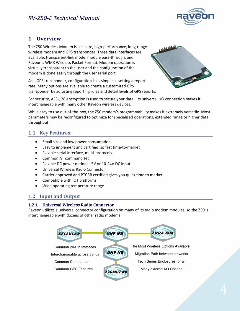
The Z50 Wireless Modem is a secure, high-performance, long-range wireless modem and GPS transponder. Three data interfaces are available, transparent-link mode, module pass-through, and Raveon’s WMX Wireless Packet Format. Modem operation is virtually transparent to the user and the configuration of the modem is done easily through the user serial port.
As a GPS transponder, configuration is as simple as setting a report rate. Many options are available to create a customized GPS transponder by adjusting reporting rules and detail levels of GPS reports.
For security, AES-128 encryption is used to secure your data. Its universal I/O connection makes it interchangeable with many other Raveon wireless devices.
While easy to use out-of-the-box, the Z50 modem’s programmability makes it extremely versatile. Most parameters may be reconfigured to optimize for specialized operations, extended range or higher data throughput.
1.1 Key Features:
Small size and low power consumption
Easy to implement and certified, so fast time-to-market
Flexible serial interface, multi-protocols.
Common AT command set
Flexible DC power options. 5V or 10-24V DC input
Universal Wireless Radio Connector
Carrier approved and PTCRB certified gives you quick time to market.
Compatible with IOT platforms
Wide operating temperature range
1.2 Input and Output
1.2.1 Universal Wireless Radio Connector Raveon utilizes a universal connector configuration on many of its radio modem modules, so the Z50 is interchangeable with dozens of other radio modems.

RV-Z50-E Technical Manual
5
The UWRC connector pin-out is as shown below
20-Pin UWRC Interface Port
Pin # Function Description
1 GND Ground
2 VCC DC Input
3 CD Carrier Detect Out.
4 TX On Pin is High when module is transmitting. Low when off, receiving, or sleeping.
5 Data In (TXD) Serial transmit data input.
6 Data Out (RXD) Serial receive data output.
7 Enable Low to shut down the module. High to enable it.
8 Sleep CPU Sleep input. Put in low-power fast-startup mode.
9 CTS Clear to send output. Indicates state of internal buffers.
10 RTS RTS input for serial flow control.
11 NC No Connection
12 VDIG 3.3V output. Limit current draw on this power source to 50mA.
13 IOA IO port A, USB DP
14 IOB IO port B, USB port, DM
15 IOC IO port C
16 STAT1 Status IO 1
17 NC No Connection
18 STAT2 Status LED out
19 GND System Ground
20 V-BACK Optional Backup Battery In
The primary connector is fully pin-for-pin compatible with M8 UHF, VHF, 220MHZ modems. V50 ISM band radio modems.
1.2.2 LED By default, the LED on the Z50 modem module will indicate the following:
Green: Radio has received a packet
Red: Radio is transmitting a packet
Flashing Orange: GPS is trying to lock onto GPS or GLONASS satellite signals. (Flashing will cease when Z50 has position lock from satellites)
Many commands modify the operation of the LED, including disabling it entirely. The ATL command can disable the LED on the module, saving power consumption.
1.2.3 RF Antenna Connection The RF Antenna Connection on the Z50 is an MMCX female. A typical mating connector, MMCX male, is a RMX-9010-1B from RF Industries.
RV-Z50-E Technical Manual
6
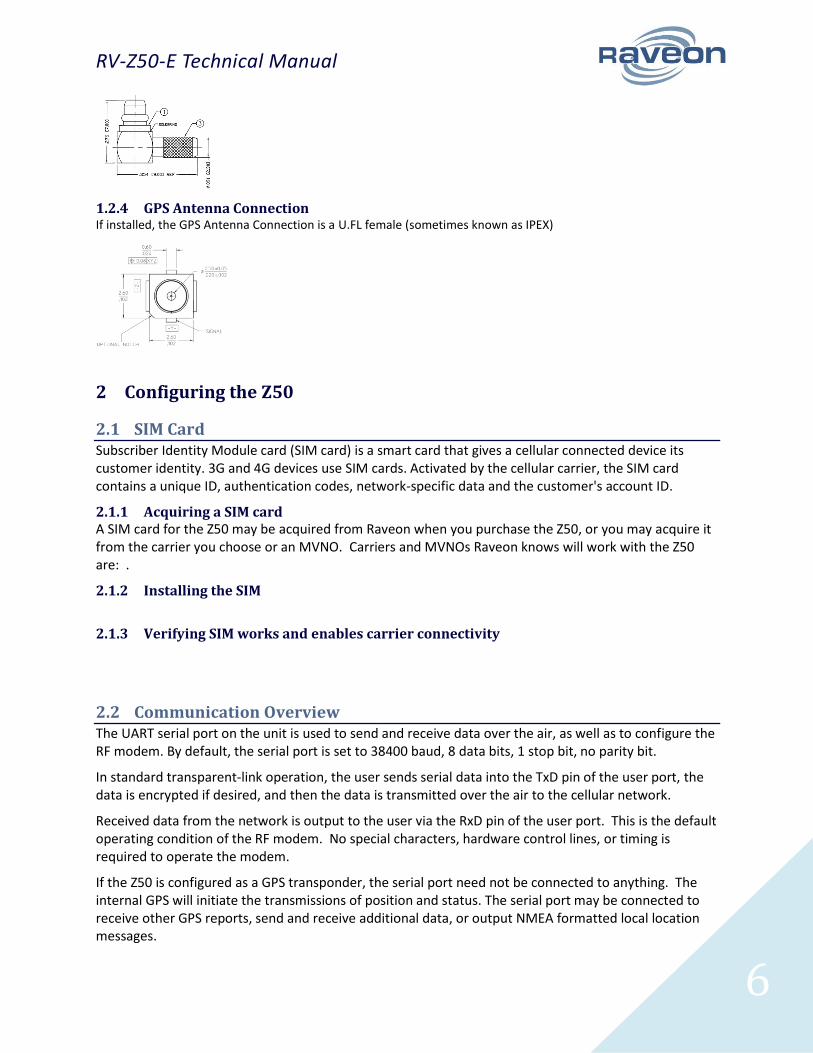
1.2.4 GPS Antenna Connection If installed, the GPS Antenna Connection is a U.FL female (sometimes known as IPEX)
2 Configuring the Z50
2.1 SIM Card Subscriber Identity Module card (SIM card) is a smart card that gives a cellular connected device its customer identity. 3G and 4G devices use SIM cards. Activated by the cellular carrier, the SIM card contains a unique ID, authentication codes, network-specific data and the customer's account ID.
2.1.1 Acquiring a SIM card A SIM card for the Z50 may be acquired from Raveon when you purchase the Z50, or you may acquire it from the carrier you choose or an MVNO. Carriers and MVNOs Raveon knows will work with the Z50 are: .
2.1.2 Installing the SIM
2.1.3 Verifying SIM works and enables carrier connectivity
2.2 Communication Overview The UART serial port on the unit is used to send and receive data over the air, as well as to configure the RF modem. By default, the serial port is set to 38400 baud, 8 data bits, 1 stop bit, no parity bit.
In standard transparent-link operation, the user sends serial data into the TxD pin of the user port, the data is encrypted if desired, and then the data is transmitted over the air to the cellular network.
Received data from the network is output to the user via the RxD pin of the user port. This is the default operating condition of the RF modem. No special characters, hardware control lines, or timing is required to operate the modem.
If the Z50 is configured as a GPS transponder, the serial port need not be connected to anything. The internal GPS will initiate the transmissions of position and status. The serial port may be connected to receive other GPS reports, send and receive additional data, or output NMEA formatted local location messages.

RV-Z50-E Technical Manual
7
The Z50 can be put into a Command Mode that used to program and configure the product. In the Command Mode, the Z50 accepts commands via the serial port TxD pin. The commands can be used to change certain internal parameters of the modem as well as to read-out the current configuration and diagnostic statistics.
The Z50 also supports Raveon’s Wireless Modem Exchange (WMX) protocol for commanding and messaging. WMX is ideal for fully automated control and tighter system integration. For more information, see the WMX Protocol Description document and the Raveon Tech Note “Rapid Radio Configuration using WMX”.
3 Command Mode
Command Mode is used to program and configure the modem. This mode is separate from data mode and will not transmit received data over-the-air, instead executing commands detailed in this manual.
3.1 Command Mode Encoding and Line Format In Command Mode, all characters are ASCII encoded. All output lines will use the standard network line ending, CR+LF (ASCII 0x0D followed by ASCII 0x0A).
Inputs lines may use either CR, LF or CR+LF line endings.
3.2 Entering Command Mode The modem may be put into a Command Mode, by entering a sequence of three plus characters (+++), called the Entry Sequence. To keep the modem from unintentionally entering the Command Mode because of the Entry Sequence occurring in a stream of data entering the modem, there must be a pause in the data stream before the Entry Sequence as well as a pause afterwards. If either pause is missing, the modem will not enter the command mode. The pause length is configurable, by default it is 500ms.
When the modem first enters the Command Mode, it will output the base model number along with the OK sequence:
RV-Z50 OK
Once in command mode, the instructions in the following sections can be followed to continue radio configuration.
3.3 Exiting Command Mode To exit command mode and return to data mode, the command EXIT may be used.
Alternatively, command mode will timeout after a configurable amount of time, by default 60 seconds.
3.4 Using Commands To execute a command, send the command name and any parameters separated by spaces, followed by a line ending. For example, to use the ATDT command to set the destination address to 1234, send:
ATDT 1234<LF>

RV-Z50-E Technical Manual
8
Some commands may output result information on lines following the command, but the output will always terminate with either the OK sequence (introduced in the previous section) or the ERROR sequence (ERROR<CR><LF>).
Some commands may have different results depending on the number of parameters. In general, a command that sets a parameter(s) can read back its values by issuing the command with no parameters.
To get on-line help with a command, enter the command with a question mark at the end.
To see a list of all commands, use the HELP command.
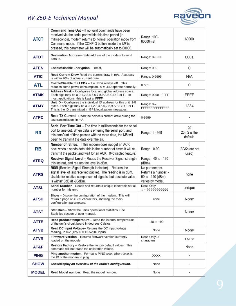
3.5 Configuration Commands The following commands are standard Raveon commands implemented by the modem.
Command Command Description Parameters Factory Default
EXIT Exit command mode, do not open the link connection.
ATDT
Exit command mode and open link. A parameter after the ATDT command will be interpreted as the link hostname to use. If there is no parameter, the default host is used, as set by the ACHN command.
ACCN Set/read the connect string. 1-16 characters. Set it to X to have the device pass the carrier’s connect string through.
CONNECT
ACDN Set/read the no-connect string. 1-16 characters. Set it to X to have the device pass the carrier’s connect string through.
DISCONNECT
ACEN Set/read the disconnect string. 1-16 characters. Set it to X to have the device pass the carrier’s connect string through.
EOF
ATAK Enable/Disable ARQ – When ARQ is enabled, this modem will automatically send an ACK packet back to a modem that sends it data. 0=off, 1=on.
Range: 0 – 1 0 (no AKCs sent)
ATAT Silence AFTER Sequence - Sets period of silence after the command sequence characters in mS.
Range:0 – 1000 (mS)
500
ATBD
Baud Rate – Sets serial com port baud rate (bps). Over-the-air (throughput) baud rate is set with ATR2 command. If a PC’s serial baud rate is set higher than the fixed over-the-air baud rate of the module, hardware handshaking may be required.
Range: 0 – 7 0 = 1200 5= 38400 1 = 2400 6=57600 2 = 4800 7=115200 3 = 9600 4 = 19200
5
ATBT Silence BEFORE Sequence – Sets period of silence before the command sequence character in mS.
Range: 0-1000 mS
500
ATBW
Set/Read IF Bandwidth - Sets the IF bandwidth to narrow (N) or wide (W). Narrow is for 12.5kHz channels, and wide is for 25 or 30kHz spaced channels. This command is only used on the VHF version of the product. The UHF does not support w
N N or W
RV-Z50-E Technical Manual
9
ATCT
Command Time Out – If no valid commands have been received via the serial port within this time period (in milliseconds), modem returns to normal operation mode from Command mode. If the CONFIG button inside the M8 is pressed, this parameter will be automatically set to 60000.
Range: 100-60000mS
60000
ATDT Destination Address– Sets address of the modem to send data to.
Range: 0-FFFF 0001
ATEN Enable/Disable Encryption. 0=0ff, Range: 0-6 0
ATIC Read Current Draw Read the current draw in mA. Accuracy is within 20% of actual current draw.
Range: 0-9999 N/A
ATL Enable/Disable the LEDs – 1 = LEDs always off. This reduces some power consumption. 0 = LED operate normally.
0 or 1 0
ATMK Address Mask – Configures local and global address space. Each digit may be a 0,1,2,3,4,5,6,7,8,9,A,B,C,D,E,or F. In most applications, this is kept at FFFF.
Range: 0000 - FFFF FFFF
ATMY Unit ID – Configures the individual ID address for this unit. 1-8 bytes. Each digit may be a 0,1,2,3,4,5,6,7,8,9,A,B,C,D,E,or F. This is the ID transmitted in GPS/localization messages.
Range: 0 – FFFFFFFFFFFFFFF
1234
ATPC Read TX Current. Read the device’s current draw during the
last transmission, in mA. 0-9999 -
R3
Serial Port Time Out – The time in milliseconds for the serial port to time out. When data is entering the serial port, and this amo0unt of time passes with no more data, the M8 will begin to transmit the data over the air.
Range: 1 - 999
20 20mS is the
default.
RB Number of retries. If this modem does not get an ACK back when it sends data, this is the number of times it will re-transmit the packet and wait for an ACK. 0=disabled feature.
Range: 0-99
0
(ACKs are not used)
ATRQ Receiver Signal Level – Reads the Receiver Signal strength this instant, and returns the level in dBm.
Range: -40 to –130 (dBm)
-
ATRS
RSSI (Receive Signal Strength Indicator) – Returns the signal level of last received packet. The reading is in dBm. Usable for relative comparison of signals, but absolute value is within10dB at -90dBm.
No parameters. Returns a number: -50 to –140 (dBm) varies by model.
none
ATSL Serial Number – Reads and returns a unique electronic serial number for this unit.
Read Only
1 - 99999999999 unique
ATSH Show – Display the configuration of the modem. This will return a page of ASCII characters, showing the main configuration parameters.
none None
ATST Statistics – Show the unit’s operational statistics. See Statistics section of user manual.
None
ATTE Read product temperature – Read the internal temperature of the unit’s circuit board in degrees Celsius.
-40 to +99 -
ATVB Read DC input Voltage– Returns the DC input voltage reading, in mV (12500 = 12.5VDC input).
None None
ATVR Firmware Version – Returns firmware version currently loaded on the module.
Read Only, 3 characters
none
AT&F Restore Factory – Restore the factory default values. This command will not erase the calibration values. None
PING Ping another modem. Format is PING xxxx, where xxxx is the ID of the modem to ping.
XXXX -
SHOW Show/display an overview of the radio’s configuration. None -
MODEL Read Model number. Read the model number. None -
RV-Z50-E Technical Manual
10
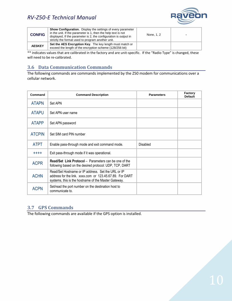
CONFIG
Show Configuration. Display the settings of every parameter in the unit. If the parameter is 1, then the help text is not displayed, If the parameter is 2, the configuration is output in strictly the format used to program another unit.
None, 1, 2 -
AESKEY Set the AES Encryption Key. The key length must match or exceed the length of the encryption scheme (128/256 bit)
** indicates values that are calibrated in the factory and are unit-specific. If the “Radio Type” is changed, these will need to be re-calibrated.
3.6 Data Communication Commands The following commands are commands implemented by the Z50 modem for communications over a cellular network.
Command Command Description Parameters Factory Default
ATAPN Set APN
ATAPU Set APN user name
ATAPP Set APN password
ATCPIN Set SIM card PIN number
ATPT Enable pass-through mode and exit command mode. Disabled
++++ Exit pass-through mode if it was operational.
ACPR Read/Set Link Protocol – Parameters can be one of the following based on the desired protocol: UDP, TCP, DART
ACHN Read/Set Hostname or IP address. Set the URL or IP address for the link. xxxx.com or 123.45.67.89. For DART systems, this is the hostname of the Master Gateway.
ACPN Set/read the port number on the destination host to communicate to.
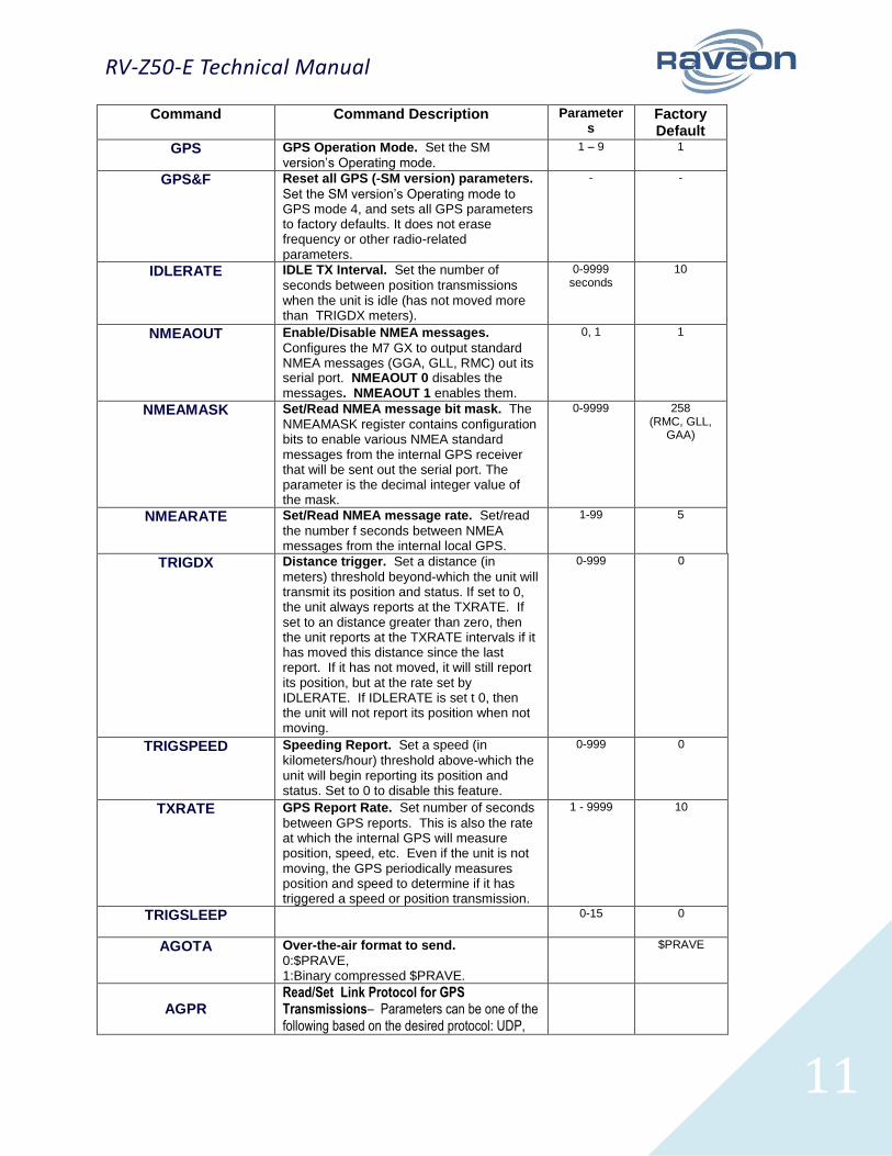
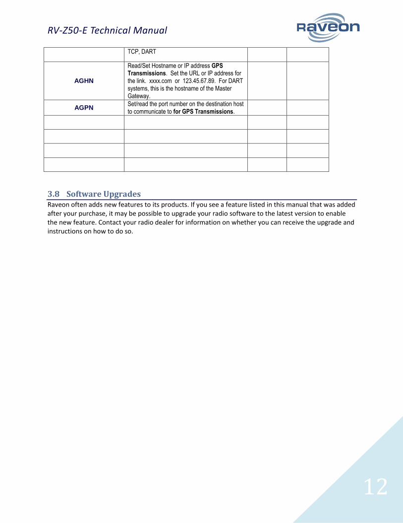
3.7 GPS Commands The following commands are available if the GPS option is installed.
RV-Z50-E Technical Manual
11
Command Command Description Parameters
Factory Default
GPS GPS Operation Mode. Set the SM
version’s Operating mode.
1 – 9 1
GPS&F Reset all GPS (-SM version) parameters.
Set the SM version’s Operating mode to GPS mode 4, and sets all GPS parameters to factory defaults. It does not erase frequency or other radio-related parameters.
- -
IDLERATE IDLE TX Interval. Set the number of
seconds between position transmissions when the unit is idle (has not moved more than TRIGDX meters).
0-9999 seconds
10
NMEAOUT Enable/Disable NMEA messages.
Configures the M7 GX to output standard NMEA messages (GGA, GLL, RMC) out its serial port. NMEAOUT 0 disables the messages. NMEAOUT 1 enables them.
0, 1 1
NMEAMASK Set/Read NMEA message bit mask. The
NMEAMASK register contains configuration bits to enable various NMEA standard messages from the internal GPS receiver that will be sent out the serial port. The parameter is the decimal integer value of the mask.
0-9999 258 (RMC, GLL,
GAA)
NMEARATE Set/Read NMEA message rate. Set/read
the number f seconds between NMEA messages from the internal local GPS.
1-99 5
TRIGDX Distance trigger. Set a distance (in
meters) threshold beyond-which the unit will transmit its position and status. If set to 0, the unit always reports at the TXRATE. If set to an distance greater than zero, then the unit reports at the TXRATE intervals if it has moved this distance since the last report. If it has not moved, it will still report its position, but at the rate set by IDLERATE. If IDLERATE is set t 0, then the unit will not report its position when not moving.
0-999 0
TRIGSPEED Speeding Report. Set a speed (in
kilometers/hour) threshold above-which the unit will begin reporting its position and status. Set to 0 to disable this feature.
0-999 0
TXRATE GPS Report Rate. Set number of seconds
between GPS reports. This is also the rate at which the internal GPS will measure position, speed, etc. Even if the unit is not moving, the GPS periodically measures position and speed to determine if it has triggered a speed or position transmission.
1 - 9999 10
TRIGSLEEP 0-15 0
AGOTA Over-the-air format to send.
0:$PRAVE, 1:Binary compressed $PRAVE.
$PRAVE
AGPR Read/Set Link Protocol for GPS Transmissions– Parameters can be one of the following based on the desired protocol: UDP,
RV-Z50-E Technical Manual
12
TCP, DART
AGHN
Read/Set Hostname or IP address GPS Transmissions. Set the URL or IP address for the link. xxxx.com or 123.45.67.89. For DART systems, this is the hostname of the Master Gateway.
AGPN Set/read the port number on the destination host to communicate to for GPS Transmissions.
3.8 Software Upgrades Raveon often adds new features to its products. If you see a feature listed in this manual that was added after your purchase, it may be possible to upgrade your radio software to the latest version to enable the new feature. Contact your radio dealer for information on whether you can receive the upgrade and instructions on how to do so.
RV-Z50-E Technical Manual
13
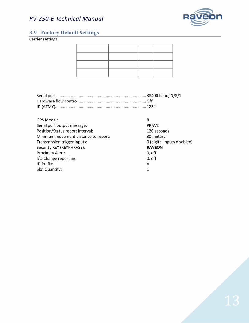
3.9 Factory Default Settings Carrier settings:
Serial port ................................................................................ 38400 baud, N/8/1 Hardware flow control ............................................................ Off ID (ATMY)................................................................................. 1234
GPS Mode : 8 Serial port output message: PRAVE Position/Status report interval: 120 seconds Minimum movement distance to report: 30 meters Transmission trigger inputs: 0 (digital inputs disabled) Security KEY (KEYPHRASE): RAVEON Proximity Alert: 0, off I/O Change reporting: 0, off ID Prefix: V Slot Quantity: 1
RV-Z50-E Technical Manual
14
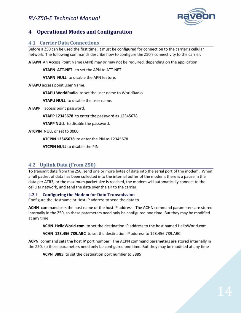
4 Operational Modes and Configuration
4.1 Carrier Data Connections Before a Z50 can be used the first time, it must be configured for connection to the carrier’s cellular network. The following commands describe how to configure the Z50’s connectivity to the carrier.
ATAPN An Access Point Name (APN) may or may not be required, depending on the application.
ATAPN ATT.NET to set the APN to ATT.NET
ATAPN NULL to disable the APN feature.
ATAPU access point User Name.
ATAPU WorldRadio to set the user name to WorldRadio
ATAPU NULL to disable the user name.
ATAPP access point password.
ATAPP 12345678 to enter the password as 12345678
ATAPP NULL to disable the password.
ATCPIN NULL or set to 0000
ATCPIN 12345678 to enter the PIN as 12345678
ATCPIN NULL to disable the PIN.
4.2 Uplink Data (From Z50) To transmit data from the Z50, send one or more bytes of data into the serial port of the modem. When a full packet of data has been collected into the internal buffer of the modem; there is a pause in the data per ATR3; or the maximum packet size is reached, the modem will automatically connect to the cellular network, and send the data over the air to the carrier.
4.2.1 Configuring the Modem for Data Transmission Configure the Hostname or Host IP address to send the data to.
ACHN command sets the host name or the host IP address. The ACHN command parameters are stored internally in the Z50, so these parameters need only be configured one time. But they may be modified at any time
ACHN HelloWorld.com to set the destination IP address to the host named HelloWorld.com
ACHN 123.456.789.ABC to set the destination IP address to 123.456.789.ABC
ACPN command sets the host IP port number. The ACPN command parameters are stored internally in the Z50, so these parameters need only be configured one time. But they may be modified at any time
ACPN 3885 to set the destination port number to 3885
RV-Z50-E Technical Manual
15
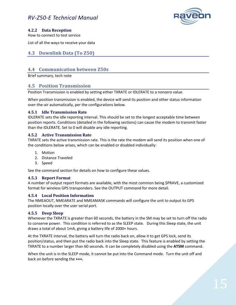
4.2.2 Data Reception How to connect to test service
List of all the ways to receive your data
4.3 Downlink Data (To Z50)
4.4 Communication between Z50s Brief summary, tech note
4.5 Position Transmission Position Transmission is enabled by setting either TXRATE or IDLERATE to a nonzero value.
When position transmission is enabled, the device will send its position and other status information over-the-air automatically, per the configurations below.
4.5.1 Idle Transmission Rate IDLERATE sets the idle reporting interval. This should be set to the longest acceptable time between position reports. Conditions (detailed in the following sections) can cause the modem to transmit faster than the IDLERATE. Set to 0 will disable any idle reporting.
4.5.2 Active Transmission Rate TXRATE sets the active transmission rate. This is the rate the modem will send its position when one of the conditions below arises, which can be enabled or disabled individually:
1. Motion 2. Distance Traveled 3. Speed
See the command section for details on how to configure these values.
4.5.3 Report Format A number of output report formats are available, with the most common being $PRAVE, a customized format for wireless GPS transponders. See the OUTPUT command for more detail.
4.5.4 Local Position Information The NMEAOUT, NMEARATE and NMEAMASK commands will configure the unit to output its GPS position locally over the user serial port.
4.5.5 Deep Sleep Whenever the TXRATE is greater than 60 seconds, the battery in the SM may be set to turn off the radio to conserve power. This condition is referred to as the SLEEP state. During this Sleep state, the unit draws a total of about 1mA, giving a battery life of 2000+ hours.
At the TXRATE interval, the battery will turn the radio back on, allow it to get GPS lock, send its position/status, and then put the radio back into the Sleep state. This feature is enabled by setting the TXRATE to a number larger than 60 seconds. It can be completely disabled using the ATSM command.
When the unit is in the SLEEP mode, it cannot be put into the Command mode. Turn the unit off and back on before sending the +++.

RV-Z50-E Technical Manual
16
4.6 Data Reception
4.6.1 Serial Port Data When the ATLAS PT receives RS232 data over the air, it checks it for errors, and if it is error-free, it will send it out the serial port. Again, the serial port may be set to any baud rate the user wishes, and the radio receiver and transmitter will continue to operate independently of the baud rate.
4.6.2 GPS Position and Status When the ATLAS PT receives a position report and status from another Atlas SM, it will send this information out its RS232 port, formatted as configured with the GPS x command. The ATLAS PT is GPS mode 8 (GPS 8). The default output message format is Raveon’s $PRAVE message.
Change the position report output format with the OUTPUT x command. Enable/disable the local GPS NMEA data with the NMEAOUT x command (0 off, 1 on)
The position/status messages that the ATLAS PT is able to send out of its serial port are:
Message Format
Description OUTPUT x Parameter/setting
$GPWPL NMEA WayPoint List. This message is commonly used to share waypoint locations among GPS units. The ATLAS PT can output this message when it receives a position report from other ATLAS PT transponders. A GPS connected to it, should put a waypoint on its screen, and in its database, at the location specified by the RV-M7.
OUTPUT 3
$PRAVE Raveon Position & Satus. This message is sent out of the ATLAS PT when it is operating in the GPS 2 mode. This message is used by third-party and PC applications for tracking location and status information.
OUTPUT 1
$GPTLL NMEA Target Lat Long. This message is commonly sent by marine RADAR receivers to notify plotting devices of the location of a RADAR target. The ATLAS PT can output this message when it receives a position report from other ATLAS PT transponders. A plotter or display connected to it that supports the TLL message, should put an icon on its screen at the location specified by the RV-M7. The icon name is the MYID of the RV-M7 that transmitted its position over the air.
OUTPUT 2
$GPGGA NMEA GPS Position Fix Data. This message is the standard position message from a GPS receiver.
NMEAOUT 1
$GPGSV NMEA Satellites in view. This message is the standard message to indicate the number of satellites in view, and their signal quality.
NMEAOUT 1
RV-Z50-E Technical Manual
17
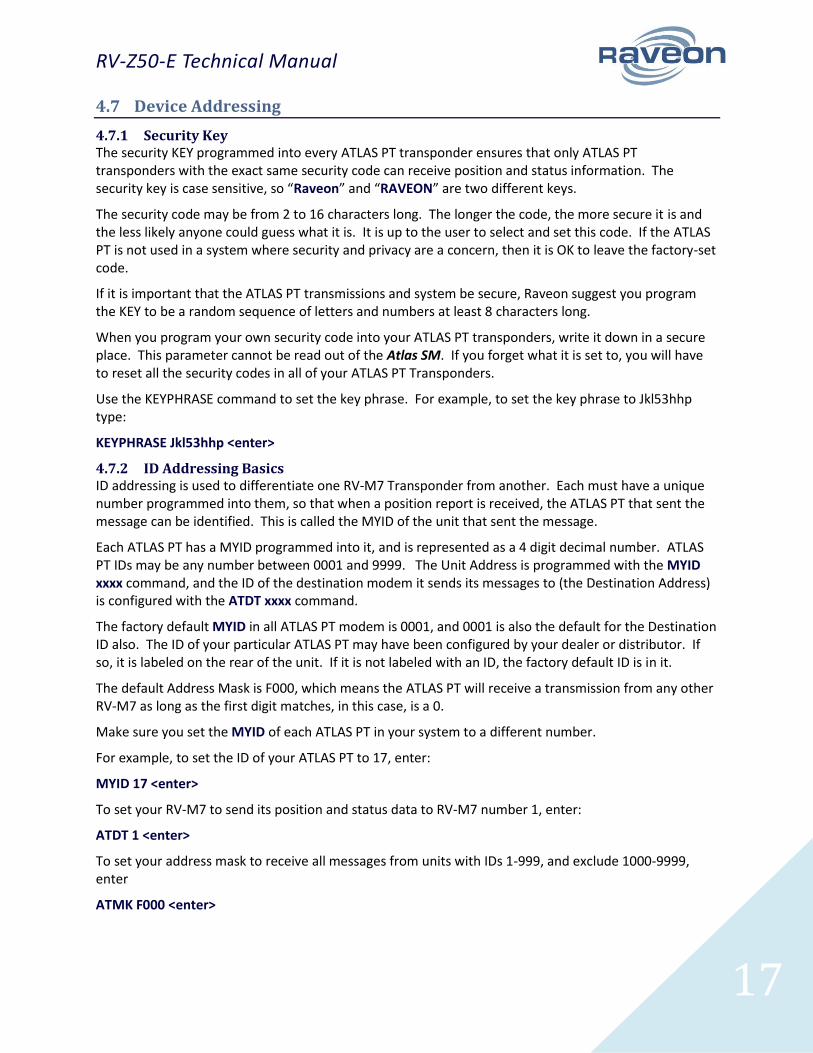
4.7 Device Addressing
4.7.1 Security Key The security KEY programmed into every ATLAS PT transponder ensures that only ATLAS PT transponders with the exact same security code can receive position and status information. The security key is case sensitive, so “Raveon” and “RAVEON” are two different keys.
The security code may be from 2 to 16 characters long. The longer the code, the more secure it is and the less likely anyone could guess what it is. It is up to the user to select and set this code. If the ATLAS PT is not used in a system where security and privacy are a concern, then it is OK to leave the factory-set code.
If it is important that the ATLAS PT transmissions and system be secure, Raveon suggest you program the KEY to be a random sequence of letters and numbers at least 8 characters long.
When you program your own security code into your ATLAS PT transponders, write it down in a secure place. This parameter cannot be read out of the Atlas SM. If you forget what it is set to, you will have to reset all the security codes in all of your ATLAS PT Transponders.
Use the KEYPHRASE command to set the key phrase. For example, to set the key phrase to Jkl53hhp type:
KEYPHRASE Jkl53hhp <enter>
4.7.2 ID Addressing Basics ID addressing is used to differentiate one RV-M7 Transponder from another. Each must have a unique number programmed into them, so that when a position report is received, the ATLAS PT that sent the message can be identified. This is called the MYID of the unit that sent the message.
Each ATLAS PT has a MYID programmed into it, and is represented as a 4 digit decimal number. ATLAS PT IDs may be any number between 0001 and 9999. The Unit Address is programmed with the MYID xxxx command, and the ID of the destination modem it sends its messages to (the Destination Address) is configured with the ATDT xxxx command.
The factory default MYID in all ATLAS PT modem is 0001, and 0001 is also the default for the Destination ID also. The ID of your particular ATLAS PT may have been configured by your dealer or distributor. If so, it is labeled on the rear of the unit. If it is not labeled with an ID, the factory default ID is in it.
The default Address Mask is F000, which means the ATLAS PT will receive a transmission from any other RV-M7 as long as the first digit matches, in this case, is a 0.
Make sure you set the MYID of each ATLAS PT in your system to a different number.
For example, to set the ID of your ATLAS PT to 17, enter:
MYID 17 <enter>
To set your RV-M7 to send its position and status data to RV-M7 number 1, enter:
ATDT 1 <enter>
To set your address mask to receive all messages from units with IDs 1-999, and exclude 1000-9999, enter
ATMK F000 <enter>
RV-Z50-E Technical Manual
18
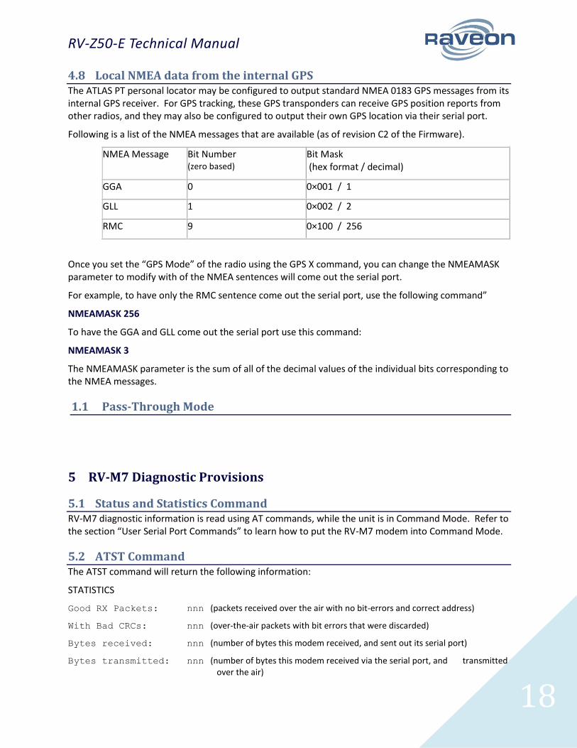
4.8 Local NMEA data from the internal GPS The ATLAS PT personal locator may be configured to output standard NMEA 0183 GPS messages from its internal GPS receiver. For GPS tracking, these GPS transponders can receive GPS position reports from other radios, and they may also be configured to output their own GPS location via their serial port.
Following is a list of the NMEA messages that are available (as of revision C2 of the Firmware).
NMEA Message Bit Number (zero based)
Bit Mask (hex format / decimal)
GGA 0 0×001 / 1
GLL 1 0×002 / 2
RMC 9 0×100 / 256
Once you set the “GPS Mode” of the radio using the GPS X command, you can change the NMEAMASK parameter to modify with of the NMEA sentences will come out the serial port.
For example, to have only the RMC sentence come out the serial port, use the following command”
NMEAMASK 256
To have the GGA and GLL come out the serial port use this command:
NMEAMASK 3
The NMEAMASK parameter is the sum of all of the decimal values of the individual bits corresponding to the NMEA messages.
1.1 Pass-Through Mode
5 RV-M7 Diagnostic Provisions
5.1 Status and Statistics Command RV-M7 diagnostic information is read using AT commands, while the unit is in Command Mode. Refer to the section “User Serial Port Commands” to learn how to put the RV-M7 modem into Command Mode.
5.2 ATST Command The ATST command will return the following information:
STATISTICS
Good RX Packets: nnn (packets received over the air with no bit-errors and correct address)
With Bad CRCs: nnn (over-the-air packets with bit errors that were discarded)
Bytes received: nnn (number of bytes this modem received, and sent out its serial port)
Bytes transmitted: nnn (number of bytes this modem received via the serial port, and transmitted over the air)
RV-Z50-E Technical Manual
19
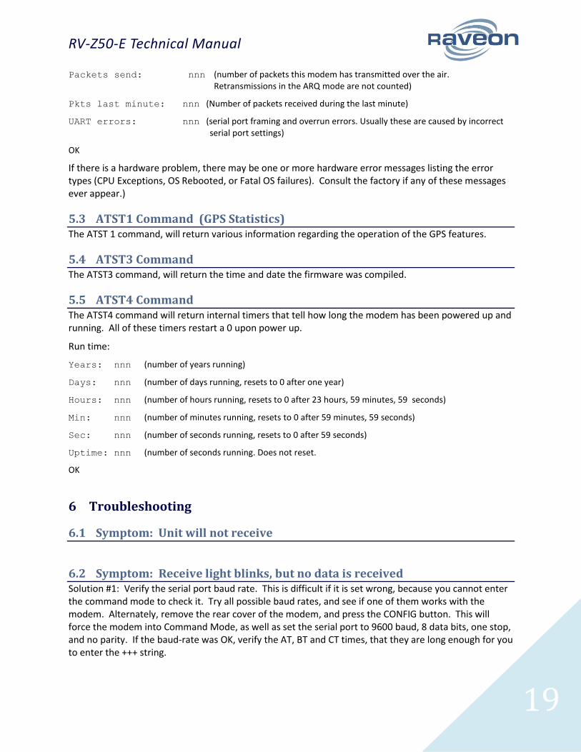
Packets send: nnn (number of packets this modem has transmitted over the air. Retransmissions in the ARQ mode are not counted)
Pkts last minute: nnn (Number of packets received during the last minute)
UART errors: nnn (serial port framing and overrun errors. Usually these are caused by incorrect serial port settings)
OK
If there is a hardware problem, there may be one or more hardware error messages listing the error types (CPU Exceptions, OS Rebooted, or Fatal OS failures). Consult the factory if any of these messages ever appear.)
5.3 ATST1 Command (GPS Statistics) The ATST 1 command, will return various information regarding the operation of the GPS features.
5.4 ATST3 Command The ATST3 command, will return the time and date the firmware was compiled.
5.5 ATST4 Command The ATST4 command will return internal timers that tell how long the modem has been powered up and running. All of these timers restart a 0 upon power up.
Run time:
Years: nnn (number of years running)
Days: nnn (number of days running, resets to 0 after one year)
Hours: nnn (number of hours running, resets to 0 after 23 hours, 59 minutes, 59 seconds)
Min: nnn (number of minutes running, resets to 0 after 59 minutes, 59 seconds)
Sec: nnn (number of seconds running, resets to 0 after 59 seconds)
Uptime: nnn (number of seconds running. Does not reset.
OK
6 Troubleshooting
6.1 Symptom: Unit will not receive
6.2 Symptom: Receive light blinks, but no data is received Solution #1: Verify the serial port baud rate. This is difficult if it is set wrong, because you cannot enter the command mode to check it. Try all possible baud rates, and see if one of them works with the modem. Alternately, remove the rear cover of the modem, and press the CONFIG button. This will force the modem into Command Mode, as well as set the serial port to 9600 baud, 8 data bits, one stop, and no parity. If the baud-rate was OK, verify the AT, BT and CT times, that they are long enough for you to enter the +++ string.
RV-Z50-E Technical Manual
20
Solution #2: Verify the KEYPHRASE is correct. If encryption is used, the KEYPHRASE is set to a unique word, and must be the same in all radios in the system. If it is not used in the radio system, then the KEYPHRASE in all units must be disabled or left at the factory default. To disable encryption, use the KEYPHRASE 0 command. The factory default KEYPHRASE is RAVEON, in all capitol letters.
6.3 Symptom: Long delay before transmitting Solution #1: Verify that serial port timeout is OK. The ATR3 command sets the number of milliseconds that the RV-M7 will look for in the serial input data stream. If a pause greater than this value happens, the modem will transmit. If the ATG0 parameter is set very large, say 2000, this means 2 seconds, and the modem may simply be waiting a long time. Typical settings for this parameter are 20 (20mS).
6.4 Symptom: Cannot enter Command Mode Solution #1: Verify the serial port baud rate. This is difficult if it is set wrong, because you cannot enter Command mode to check it. Try all possible baud rates, and see if one of them works with the modem. Alternately, remove the rear cover of the modem, and press the CONFIG button. This will force the modem into Command mode, as well as set the serial port to 9600 baud, 8 data bits, one stop, and no parity. If the baud-rate was OK, verify the AT, BT and CT times, that they are long enough for you to enter the +++ string.
Solution #2: Handshaking. You may have hardware handshaking enabled on your terminal program, but the hardware or cable may not support it. Disable hardware handshaking on your terminal program to verify this is the issue.
Solution #3: Deep Sleep. If the TXRATE is greater than 60 seconds, the unit may be put into a very deep sleep mode, and will not enter the command mode. You must first turn the unit off, and back on to put it into Command mode.
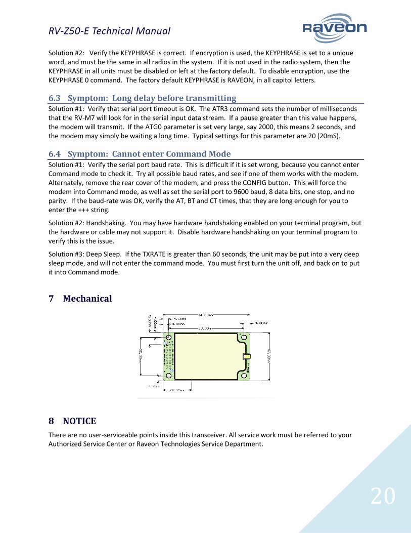
7 Mechanical
8 NOTICE
There are no user-serviceable points inside this transceiver. All service work must be referred to your Authorized Service Center or Raveon Technologies Service Department.

RV-Z50-E Technical Manual
21
8.1 Safety Training information Always use this radio with the antenna supplied with it. This radio is restricted to occupational use. Work related operations are permitted only when the radio operator has the knowledge to control the exposure conditions of its passengers and bystanders by maintaining the minimum separation distance. Failure to observe these restrictions may result in exceeding the FCC RF exposure limits.
9 FCC Compliance Information
.