Embed Size (px)
Citation preview

Technical Note - TN 016: 2017
© State of NSW through Transport for NSW 2017 Page 1 of 2
Technical Note - TN 016: 2017
Subject: 'Important Warning' replacement in various documents
Issued date: 08 June 2017
Effective date: 08 June 2017
For queries regarding this document [email protected]
www.asa.transport.nsw.gov.au
This technical note is issued by the Asset Standards Authority (ASA) to amend the following
documents:
• T MU AM 01002 MA Maintenance Requirements Analysis Manual, version 1.0
• T MU MD 00003 GU Guide to Independent Safety Assessment, version 1.0
• T MU MD 00004 TI Independent Safety Assessor (ISA) Requirements (Interim), version 1.0
The 'Important Warning', which appears on the front cover of these documents, shall be replaced
in its entirety with the following:
Important message
This document is one of a set of standards developed solely and specifically for use on Transport Assets (as defined in the Asset Standards Authority Charter). It is not suitable for any other purpose. The copyright and any other intellectual property in this document will at all times remain the property of the State of New South Wales (Transport for NSW). You must not use or adapt this document or rely upon it in any way unless you are providing products or services to a NSW Government agency and that agency has expressly authorised you in writing to do so. If this document forms part of a contract with, or is a condition of approval by a NSW Government agency, use of the document is subject to the terms of the contract or approval. To be clear, the content of this document is not licensed under any Creative Commons Licence. This document may contain third party material. The inclusion of third party material is for illustrative purposes only and does not represent an endorsement by NSW Government of any third party product or service. If you use this document or rely upon it without authorisation under these terms, the State of New South Wales (including Transport for NSW) and its personnel does not accept any liability to you or any other person for any loss, damage, costs and expenses that you or anyone else may suffer or incur from your use and reliance on the content contained in this document. Users should exercise their own skill and care in the use of the document. This document may not be current and is uncontrolled when printed or downloaded. Standards may be accessed from the Asset Standards Authority website at www.asa.transport.nsw.gov.au

Technical Note - TN 016: 2017
© State of NSW through Transport for NSW 2017 Page 2 of 2
Authorisation:
Technical content prepared by
Checked and approved by
Authorised for release
Signature
Date
Name Ken Lewis Bopha Lam Jagath Peiris
Position Project Manager A/Manager Network Standards
A/Director Network Standards and Services

Technical Note - TN 070: 2015
Technical Note - TN 070: 2015
Subject: Amendment to T MU AM 01002 MA - Age (X axis) reliability (y axis) pattern
Issued date: 19 November 2015
Effective date: 19 November 2015
For queries regarding this document [email protected]
www.asa.transport.nsw.gov.au
This technical note amends ASA Engineering Manual: T MU AM 01002 MA Maintenance
Requirements Analysis Manual, Version 1.0, issued on 9 July 2014.
1. Amendment Figure 5 is replaced by the following:
Figure 5 - Age (X axis) reliability (y axis) pattern
Wear-in then Random 68%
Random over measurable life
14%
Increasing during Wear-in and then Random
7%
Steadily Increasing
5%
Random then Wear Out
2%
Wear-In to Random to Wear Out
4%
© State of NSW through Transport for NSW Page 1 of 2

Technical Note - TN 070: 2015
Authorisation:
Technical content prepared by
Checked and approved by
Interdisciplinary coordination checked by
Authorised for release
Signature
Name Rana Roy Angelo Koutsoukos Toby Horstead Graham Bradshaw
Position Asset Reliability Specialist
Manager Asset Stewardship
Principal Manager Network and Asset Strategy
Director Network Standards and Services
© State of NSW through Transport for NSW Page 2 of 2

Maintenance Requirements Analysis Manual
T MU AM 01002 MA
Management standard
Version 1.0 Issued Date: 09 July 2014 Effective Date: 09 July 2014Reconfirmed: 25 July 2019
Important Warning
This document is one of a set of standards developed solely and specifically for use on the rail network owned or managed by the NSW Government and its agencies. It is not suitable for any other purpose. You must not use or adapt it or rely upon it in any way unless you are authorised in writing to do so by a relevant NSW Government agency.
If this document forms part of a contract with, or is a condition of approval by, a NSW Government agency, use of the document is subject to the terms of the contract or approval.
This document may not be current. Current standards are available for download from the Asset Standards Authority website at www.asa.transport.nsw.gov.au
© State of NSW through Transport for NSW

T MU AM 01002 MA Maintenance Requirements Analysis Manual
Version 1.0 Effective Date: 09 Jul 2014
© State of NSW through Transport for NSW Page 2 of 135
Standard Approval Owner: A Koutsoukos, Manager Asset Stewardship, Network and Asset Strategy, Asset
Standards Authority Authorised by: T Horstead, Principal Manager, Network and Asset Strategy, Asset Standards
Authority Approved by: Approved by J Modrouvanos, Director Asset Standards Authority on behalf of ASA
Configuration Control Board
Document Control Version Summary of Change 1.0 First issue
For queries regarding this document
www.asa.transport.nsw.gov.au

T MU AM 01002 MA Maintenance Requirements Analysis Manual
Version 1.0 Effective Date: 09 Jul 2014
© State of NSW through Transport for NSW Page 3 of 135
Preface
The Asset Standards Authority (ASA) develops, controls, maintains, and publishes standards
and documentation for transport assets for New South Wales, using expertise from the
engineering functions of the ASA and industry.
The Asset Standards Authority publications include the network and asset standards for NSW
Rail Assets.
This manual has been developed from the RailCorp publication AM 9995 PM Maintenance
Requirements Analysis Manual and has been issued by the Asset Standards Authority to
provide guidance for maintenance requirement analysis.
This manual supersedes AM 9995 PM Maintenance Requirements Analysis Manual.

T MU AM 01002 MA Maintenance Requirements Analysis Manual
Version 1.0 Effective Date: 09 Jul 2014
© State of NSW through Transport for NSW Page 4 of 135
Table of contents
1. Executive review ...............................................................................................................................5
1.1 Introduction .......................................................................................................................................5
2. Background and theory..................................................................................................................13
2.1 Definition of terms and acronyms.................................................................................................13 2.2 Reliability and maintenance...........................................................................................................18 2.3 Maintenance, risk and RCM ...........................................................................................................24
3. System analysis ..............................................................................................................................36
3.1 Introduction .....................................................................................................................................36 3.2 Failure modes and effects analysis (FMEA).................................................................................48 3.3 Criticality analysis...........................................................................................................................63
4. RCM analysis ...................................................................................................................................77
4.1 Task analysis ...................................................................................................................................77 4.2 Frequency determination ...............................................................................................................93 4.3 Task packaging .............................................................................................................................101
5. Audit and evaluation.....................................................................................................................107
5.1 Auditing..........................................................................................................................................107 5.2 Test and evaluation.......................................................................................................................112 5.3 Technical maintenance plans ......................................................................................................115
6. MRA techniques and policy .........................................................................................................117
6.1 Age exploration .............................................................................................................................117 6.2 Task frequency algorithms ..........................................................................................................119 6.3 Level of repair analysis ................................................................................................................124 6.4 MRA policy.....................................................................................................................................127
7. Analysis of safety critical items...................................................................................................130
7.1 Introduction ...................................................................................................................................130
Appendix A - Packaging guidelines............................................................................................................133

T MU AM 01002 MA Maintenance Requirements Analysis Manual
Version 1.0 Effective Date: 09 Jul 2014
© State of NSW through Transport for NSW Page 5 of 135
1. Executive review
1.1 Introduction
This manual supports the TfNSW Asset Management Policy with detailed processes for
undertaking a maintenance requirement analysis This includes the determination of
preventive maintenance requirements of both 'in-service' and new assets. This process,
along with the identification of all corrective maintenance needs of a system, supports the
development of maintenance plan.
The manual is not meant to stand alone and should be read in conjunction with the
reference documents at the end of each section. These references have been assessed
as 'world best practice' and provide additional detail to staff tasked with undertaking
maintenance requirements analysis.
This manual is primarily directed at engineers responsible for establishing and
undertaking maintenance policies contained in technical maintenance plans. Other staff
involved in the technical management and maintenance of capital assets would also
benefit from a conceptual knowledge of the process.
1.1.1 Maintenance requirements analysis (MRA)
The determination of maintenance requirements is a significant process, which consist of
preventive and corrective maintenance procedures. These procedures are related to both
the physical and functional configurations of items comprising a system and recognise
that the operating context or environment of equipment is a critical contributor to system
maintenance needs.
Reliability-centred maintenance1 (RCM) analysis is a 'world class' standardised
maintenance requirements analysis (MRA) process now accepted by, and applied
across, all TfNSW engineering disciplines for the development of system preventive
maintenance requirements. The RCM process derives from the application of failure
modes, effects and criticality analysis (FMECA) and recognises that preventive
maintenance can only, at best, enable assets to achieve their built-in level of reliability.
RCM programs require the selection of preventive maintenance tasks on the basis of the:
reliability characteristics of the equipment
operating context of the equipment (that is; its environment)
logical analysis of the failure consequences
1 Anthony Smith, Reliability-Centred Maintenance, McGraw-Hill, 1993, John Moubray, RCM II Reliability-Centred Maintenance,
Butterworth Heinemann, 1992 and US MIL-STD-2173AS, Reliability-Centred Maintenance for Naval Aircraft Weapons and Support Equipment.

T MU AM 01002 MA Maintenance Requirements Analysis Manual
Version 1.0 Effective Date: 09 Jul 2014
© State of NSW through Transport for NSW Page 6 of 135
The RCM process is supported by a level of repair analysis (LORA)2. LORA identifies the
most cost effective corrective maintenance strategy for failed items, that is to maintain or
to dispose of failed items and, if maintain, the organisational level at which that
maintenance strategy will be applied. FMECA, RCM and LORA combined provide a
comprehensive set of analysis tools to determine, either at the design stage or later in-
service, an equipment's complete set of preventive and corrective maintenance
requirements and the organisational level at which that maintenance will be done.
1.1.2 FMECA and RCM analysis
Failure mode effects and criticality analysis3 (FMECA) is a standard tool for identifying
and prioritising the failure potential of a design. It is usually conducted during the
developmental stage in order to prioritise design actions aimed at their (failure potential)
removal during that stage. Removal of high risk failure modes early in the design process
has significant economic advantages and will usually more than justify the additional
investment necessary to conduct a FMECA during the acquisition phase4.
a) New capital assets
Application of the FMECA process was originally established to support military
equipment procurement activity; however the process is now rapidly expanding to
non-military equipment5. “Process FMECA”6 extends the original hardware design
FMECA concept into production and other process type activity to identify all possible
failures, hardware and human, and establish effective control mechanisms.
For newly acquired assets, the failure mode effects analysis (FMEA) element of the
FMECA is used as raw information for RCM analysis. This information combined with the
functional specifications required by the acquisition methodology; provide the basic data
for undertaking RCM analysis. The RCM analysis for new assets should be the
responsibility of the prime system supplier and the subsequent documentation should be
a contract deliverable.
The analysis sequence for new assets is shown at Figure 1.
Figure 1 - Maintenance requirements analysis elements
ESTABLISH
FUNCTIONS
UNDERTAKE
FMECA
UNDERTAKE
RCM
UNDERTAKE
LORA
MAINTENANCE
REQUIREMENTS
ANALYSIS
COMPLETE
2 US MIL-STD-1390C, Level of Repair Analysis.
3 US MIL-STD-1629A / IEC 60812 A Procedure for a Failure Mode Effects and Criticality Analysis. 4 Blanchard, Logistics Engineering and Management 5 US MIL-HDBK-338-1A, Electronic Reliability Design Handbook, US Department of Defence, 1988. 6 US MIL-HDBK-338-1A, Electronic Reliability Design Handbook, US Department of Defence, 1988.

T MU AM 01002 MA Maintenance Requirements Analysis Manual
Version 1.0 Effective Date: 09 Jul 2014
© State of NSW through Transport for NSW Page 7 of 135
b) Existing assets
The application of RCM analysis to existing assets usually means that there is no
pre-established FMECA data to work with and hence considerable work must be done to
establish functional relationships and FMEA data. This process requires intensive staff
resources. The establishment of functional relationships can take up to 40% of the total
time but usually provides considerable insights into the equipment and its functions.
Major reasons for implementing maintenance requirements analysis on existing assets
are to:
improve the understanding of all engineering and maintenance staff as to what is
the equipment's function and how this supports the business
establish a baseline of functional failures and their compensating redesign,
operational or maintenance tasks
establish an optimised preventive maintenance program that matches business
needs and the inherent reliability characteristics of the equipment
A basic seven step process for undertaking RCM analysis in accordance with the
principles contained in referenced standards and guidelines is shown at Figure 2.
Experience indicates that 12 months to 18 months is required to complete a
comprehensive analysis and implement a significant RCM program on an existing asset.
However, a 'fast track' analysis process which bypasses some of the more onerous
quality assurance aspects of a formal analysis program can be achieved in much shorter
time but at the sacrifice of some accuracy. The 'fast track' is generally used to rapidly
establish a documented maintenance 'baseline' for existing assets with established
maintenance programs to enable the implementation of an effective prioritised continual
improvement program.
The output from either the comprehensive or fast track process is a set of preventive
maintenance tasks which achieve necessary levels of safety and availability at minimum
life cycle cost commensurate with the inherent characteristics of the design.
The RCM analysis process is usually an initial 'best guess' that will require review as
assumptions made during the analysis are verified or otherwise by service performance.
Additionally, changes to operational requirements, system configuration and operating
and maintenance environments will require reference back to original analysis and review
of the maintenance requirements.
The maintenance requirements analysis process that connects RCM analysis with FMEA
and the continual improvement process is shown at Figure 3.

T MU AM 01002 MA Maintenance Requirements Analysis Manual
Version 1.0 Effective Date: 09 Jul 2014
© State of NSW through Transport for NSW Page 8 of 135
Figure 2 - The seven-step reliability-centred maintenance analysis method

T MU AM 01002 MA Maintenance Requirements Analysis Manual
Version 1.0 Effective Date: 09 Jul 2014
© State of NSW through Transport for NSW Page 9 of 135
Figure 3 - Maintenance requirements analysis process (MIL-HDBK-2173(AS))

T MU AM 01002 MA Maintenance Requirements Analysis Manual
Version 1.0 Effective Date: 09 Jul 2014
© State of NSW through Transport for NSW Page 10 of 135
1.1.3 Documentation
The analysis documentation, whether electronic or hard copy, must provide the
justification for all the tasks defined in the preventive maintenance program and specified
in a technical maintenance plan (TMP). The particular details of what data has been
collected against each application will also provide the details needed to complete each
field in sufficient detail to allow systems engineers today or 20 years hence to understand
completely the reason for the existence of each and every task in the schedules without
conducting a reverse engineering exercise or redoing the analysis.
Any necessary caveats regarding the accuracy of information used, or assumptions
made, should be included with the analysis documentation associated with each asset
type.
The output of the maintenance requirements analysis process, whether hard copy or
electronic, should be maintained by a single authorised engineering manager. This
manager is responsible and accountable for the configuration control aspects of the data
as defined in an asset type's configuration management plan (CMP).
Maintenance requirements analyses are controlled documents defined in the relevant
configuration management plans.
The quality of the documentation, which will be the basis of audits and quality
improvement programs, must be maintained at all times.
1.1.4 Quality management
Quality assurance of the analysis process should be achieved through an accreditation
framework for MRA analysts.
This manual will be the prime documentation covering the maintenance requirements
analysis process and should be referred to by the quality manual framework covering the
organisation's activity.
Having produced a baseline via the RCM analysis process, every effort must be made to
continually refine the output in accordance with the principles of total quality
management. This continual refinement process follows the principle of using staff at all
levels to continually refine the analysis results. Certain analysis decisions will however
require the application of statistical analysis and engineered solutions and hence require
specially trained and accredited staff.

T MU AM 01002 MA Maintenance Requirements Analysis Manual
Version 1.0 Effective Date: 09 Jul 2014
© State of NSW through Transport for NSW Page 11 of 135
To ensure that limited engineering resources achieve their best return, activities will be
prioritised on the basis of opportunities for monetary savings or performance
improvement. Analysis candidates are identifiable either by their high resource
consumption or by demonstrating considerably less performance than benchmarked
'world best'. Prioritisation for improvement analysis will be based on a combination of the
two factors.
1.1.5 Use of this manual
This manual is not a definitive document providing all the detailed procedures and
technical knowledge necessary to undertake maintenance requirements analysis. Rather,
it should be read in conjunction with other more detailed texts included in the suggested
reading material from which the methods have been drawn. This includes the user
manual for any electronic database used to capture information and apply decision
algorithms to determine optimum task frequencies.
This manual provides:
a tailored beginner’s manual for applying RCM analysis to non-safety critical
equipment (closure on safety critical failures shall require a further HAZOP or
equivalent safety analysis refer Section 7)
an RCM guide for those accredited in RCM analysis
adequate explanation for those not involved in the process of maintenance
requirements analysis to understand the concept
necessary text for the training of staff that will provide specialist technical
knowledge during an RCM analysis project under guidance from a trained
facilitator
1.1.6 References
There are a number of reference texts that either explain the RCM analysis process in
detail or in some way provide support to the total process of producing preventive
maintenance programs.
Available RCM procedural texts are all based on the same original work conducted during
the development of the maintenance steering group procedures of the International Air
Transport Association. Detailed directions for RCM analysis are contained in the four
primary references listed below:
Nowlan and Heap, United Airlines, San Francisco, California, 1978
United States Military Standard MIL-HDBK-2173(AS), Reliability-Centred
Maintenance for Naval Aircraft Weapons and Support Equipment. 1992

T MU AM 01002 MA Maintenance Requirements Analysis Manual
Version 1.0 Effective Date: 09 Jul 2014
© State of NSW through Transport for NSW Page 12 of 135
Smith, Reliability-Centred Maintenance, McGraw Hill, 1992
Moubray, RCMII Reliability-Centred Maintenance, 1991
The documents listed below are also recommended as further reading for those who
intend to extend their knowledge of the MRA process and associated reliability
engineering techniques applied as part of a systems engineering process.
Maintenance Steering Group 3 Report. 1980
United States Military Standard MIL-STD-2169A, A procedure for a Failure Mode,
Effect and Criticality Analysis. 1977
Blanchard, Logistics Engineering and Management, Wiley Interscience, 1986
Blanchard, Systems Engineering and Management, Wiley Interscience, 1991
US MIL-HDBK-338B, Electronic Reliability Design Handbook, 1998
United States Military Standard MIL-STD-1388-1A / MIL-HDBK-502 Logistic
Support Analysis, 1991
AMCP (US Army Material Command), 706-132
1.1.7 Suggested readings and references
The suggested additional readings for this section are listed below.
TfNSW Asset Management Policy
Nowlan & Heap, Reliability-Centred Maintenance
United States Military Standard MIL-HDBK-2173(AS)
Moubray, RCMII
Smith, Reliability-Centred Maintenance
MSG 3 Report

T MU AM 01002 MA Maintenance Requirements Analysis Manual
Version 1.0 Effective Date: 09 Jul 2014
© State of NSW through Transport for NSW Page 13 of 135
2. Background and theory
2.1 Definition of terms and acronyms
The following terms and definitions are used within this manual:
actuarial analysis statistical analysis of failure data to determine the age-reliability
characteristics of an item
age exploration the process of determining age-reliability relationships through
controlled testing and analysis of chance or unintentional events of safety critical items;
and from operating experience for non-safety items
application the set of assets defined by a single Technical Maintenance Plan and hence
given a single accountability for engineering management
check task a scheduled task requiring measurement of some parameter and its
comparison to a required standard (accept/reject criteria)
commercial off-the-shelf applies to equipment and software which are part of the
manufacturer’s / supplier’s standard product
conditional (also potential) failure the failure of an item to meet a desired quantifiable
performance criteria which may be either an output or condition parameter and which
indicates that conditional risk is unacceptable
conditional probability of failure the probability that an item will fail during a particular
age interval, given that it survives to enter that age interval
configuration management plan a document that provides key managerial
accountability and local procedures for the configuration management functions of
identification, change control, status accounting and audit. Additionally, the document
provides details of the numbering and information management practices necessary for
controlling the data set required by configuration management.
consequence of failure the results, to an operating organisation, of a given functional
failure at the equipment level and classified in RCM analysis as: safety operational
economic safety hidden non-safety hidden
corrective maintenance the actions performed, as a result of failures (either functional
or conditional) to restore an item to a specified condition (MIL-STD-721B)
COTS commercial off-the-shelf
default decision in a decision tree where one of two decisions must be made, it is the
mandatory decision to be made in the absence of complete information. This may occur
in the analysis of both new and in service equipment.

T MU AM 01002 MA Maintenance Requirements Analysis Manual
Version 1.0 Effective Date: 09 Jul 2014
© State of NSW through Transport for NSW Page 14 of 135
defect any unacceptable departure of a characteristic of an entity (system, equipment,
assembly, part) requirements
discard task the scheduled removal and disposal of items or parts at a specified life or
condition of item or part (time or event) limit
double failure a failure event consisting of the sequential occurrence of the failure of a
protective function and the failure of a function it is protecting. The double failure may
have consequences that would not be produced if either of the failures occurred
separately.
effectiveness (task) the criteria for determining whether a particular task is capable of
reducing the failure rate or probability of failure to a required or acceptable level. (that is
the task is worth doing)
engineering failure mode the specific engineering mechanism of failure which leads to a
particular functional or conditional failure
examination task a scheduled task requiring visual examination for explicit evidence of
failure
fail safe a design property of a system or equipment which prevents its failure resulting in
catastrophic outcomes
failure effects the impact a particular failure mode has on the operation, function or
status of an item
failure mode the engineering mechanism of failure which leads to a particular functional
or conditional failure. It includes the manner by which the failure is observed and is
generally described by the way in which the failure occurs and its impact, if any, on
equipment operation.
failure modes effects analysis a process that identifies how a systems or equipment
fail, and identifies the effect of the failure
failure modes effects and criticality analysis which extends the FMEA to assess the
criticality of the failure on the system. (Ref MIL-STD-1629A / IEC 60812)
failure rate ratio of the total number of failures within an item population, divided by the
total number of life units expended by that population during a particular measurement
interval under stated conditions
failure the cessation of the ability of an item to perform a specified function
fault the inability of an entity to perform a required function
fault tree analysis the analysis process where by the relationship and combinations of
faults/events are established that will lead to the occurrence of a defined fault, and are
presented diagrammatically

T MU AM 01002 MA Maintenance Requirements Analysis Manual
Version 1.0 Effective Date: 09 Jul 2014
© State of NSW through Transport for NSW Page 15 of 135
fit for function means something that is good enough to the job it was designed to do
FMEA failure mode effects analysis
FMECA failure mode effects and criticality analysis
FTA fault tree analysis
functional check a task requiring measurement of some defined parameter and its
comparison against a defined standard (synonymous with a check task)
functional failure the failure of an item to perform its normal or characteristic functions
within specified limits
hidden failure a failure not evident to the operator during their performance of normal
duties
infant mortality the relatively high conditional probability of failure during the period
immediately after an item enters or returns to service. Such failures are usually due to
defects in manufacturing not prevented or detected by the quality assurance process (if
any)
inherent reliability a measure of the reliability that includes only the effects of an item
design and its application and assumes an ideal operating and support environment
level of repair analysis the process for determining on an economic basis whether
equipment should be discarded or maintained, and if so whether the maintenance is
performed on or off site
logistics support analysis the process of determining the total support requirements for
equipment or systems. (MIL-PRF-49506 Logistic Support Analysis)
LORA level of repair analysis
maintenance requirements analysis the process of identifying the appraisal, preventive
and corrective maintenance requirements of systems / equipment to allow the system /
equipment to fulfil its intended function
MDT mean down time
mean down time a measure of the period of time that an entity is unavailable for its
required function (includes mean time to repair (MTTR), logistics down time and
administrative downtime)
mean time between failure a basic measure of reliability for large repairable items which
exhibit an exponential (random) failure characteristic
mean time to failure a basic measure of reliability for large non-repairable items which
exhibit an exponential (random) failure characteristic

T MU AM 01002 MA Maintenance Requirements Analysis Manual
Version 1.0 Effective Date: 09 Jul 2014
© State of NSW through Transport for NSW Page 16 of 135
mean time to repair a basic measure of the maintainability for repairable items/systems.
It is generally taken as the mean repair time once staff are on site with the requisite
spares, tools and test equipment
MIL-HDBK United States Military Handbook
MIL-STD United States Military Standard
MRA maintenance requirements analysis
MTBF mean time between failures
MTTF mean time to failure
MTTR mean time to repair
on condition task scheduled task to detect potential failures, or to meet calibration
requirements
operational checks scheduled tasks to detect the operability of a particular function in
order to check for hidden failures
operational maintenance (also called 'organisational' and 'field' maintenance)
maintenance which is either preventive or corrective in nature and that is undertaken on
the system irrespective of whether it is operating or shut down
operator the person who uses or operates equipment as part of their allocated duties
during its normal usage
preventive maintenance the actions performed in an attempt to retain an item in a
specified condition by providing systematic inspection, detection and prevention of
incipient failure (MIL-STD-721B)
RCM reliability-centred maintenance
redundancy The existence of more than one means for accomplishing a given function.
Each means of accomplishing the function need not necessarily be identical (MIL-STD-
721B)
reliability-centred maintenance (RCM) is the maintenance based on the inherent
reliability of equipment in its operating context, directed at achieving the required levels of
safety and reliability at the minimum life-cycle cost
Note: Further information in ESI 0021 risk the combination of
the consequences of an event (including changes in
circumstances) and the associated likelihood of occurrence.
safe life limit a life limit imposed on an item that is subject to a critical failure established
as some fraction of the average age at which test data shows that failures will occur

T MU AM 01002 MA Maintenance Requirements Analysis Manual
Version 1.0 Effective Date: 09 Jul 2014
© State of NSW through Transport for NSW Page 17 of 135
secondary damage the immediate physical damage to other parts of items that result
from a specific failure mode
servicing schedule a defined set of tasks to be undertaken on an asset or set of assets
in a defined place at a defined point in time; the result of the task aggregation process
following the RCM task analysis activity
servicing the performing of any action needed to keep an item in operating condition, (for
example; lubricating, oiling, fuelling.) but not including preventive maintenance of parts or
corrective maintenance tasks
significant item an item whose failure either alone, (or if delivering a hidden function
then in conjunction with another failure), has safety, operational or major economic
consequences
technical maintenance plan a document which details: which items are to be
maintained, what maintenance tasks are to be done, and when and where the
maintenance task is to be performed
TMP technical maintenance plan
total quality management a management approach that achieves continuous
incremental improvement in all processes, goods and services through the creative
involvement of all people
wear-out the process which results in an increase of the failure rate or conditional
probability of failure with the accumulation of life units
workshop maintenance deepest level of maintenance undertaken on equipment or their
assemblies (also known as Depot level maintenance in the reference texts)

T MU AM 01002 MA Maintenance Requirements Analysis Manual
Version 1.0 Effective Date: 09 Jul 2014
© State of NSW through Transport for NSW Page 18 of 135
2.2 Reliability and maintenance
2.2.1 Introduction
While the concept of reliability is not new, its proper definition and introduction as a
branch of engineering is relatively recent. Thus 'reliability' is related to a recently
developed body of concepts and methods which date from the 1940s. Maintainability
engineering, as the branch associated with the proactive examination of the maintenance
task, is even younger.
A concise history of reliability, maintainability and safety engineering is available in
Villemeur, pages 3-147. It is strongly recommended as background reading.
2.2.2 Reliability
People in all walks of life regularly use the word reliability. We all want reliability from our
assets, be it rail vehicle, high voltage switchgear or dishwasher. Few understand that for
the professional engineer 'reliability' is a specialist word with an entire engineering
discipline behind it. A maintenance or systems engineer without an understanding of
reliability is like a surgeon without a scalpel. The necessary incisive tools are just not
there.
Reliability is defined as:
"the probability that an item will perform its intended function for a specified interval under
stated conditions"8.
The theoretical and mathematical foundations for the reliability engineering discipline are
comprehensively described in Chapter 5 of MIL-HDBK-338B9, Electronic Reliability
Design Handbook. Many other commercial texts are available on the subject. The
handbook, provides detailed but practical approaches to specifying, allocating and
predicting reliability for engineering systems and equipment.
An understanding of reliability requires more than a cursory look at the primary elements
of the definition. To assist the development of a basic understanding of these elements
and their implications, they are described in further detail as follows:
probability is a quantitative expression that follows strict mathematical rules and
can be expressed as a fraction, a percentage, or a decimal value that lies between
zero and one. Failures are described in possible terms because they can be
expected to occur at different points in time even for identical equipment operating
under identical conditions.
7 Villemeur, Alain, Reliability, availability, maintainability and safety assessment, John Wiley & Sons, 1992, pages 3-14.
8 US MIL-HDBK-338B, Electronic Reliability Design Handbook, US Department of Defence, 1998
9 US MIL-HDBK-338B, Electronic Reliability Design Handbook, US Department of Defence, 1998.

T MU AM 01002 MA Maintenance Requirements Analysis Manual
Version 1.0 Effective Date: 09 Jul 2014
© State of NSW through Transport for NSW Page 19 of 135
items being compared must have the same configuration to ensure that variation in
contributing factors is kept to a minimum. Different configurations represent
different populations of items, hence the mathematics of statistics, which requires
statistically homogenous groups (populations), cannot be properly applied without
high probability of erroneous results
satisfactory performance requires that specific and measurable criteria have been
established to determine what is satisfactory. This set of quantitative and
qualitative criteria is usually (should be) contained within the system specification
specified operating conditions include environmental conditions, operational profile
or other such factors which drive the variability of stresses to which the item is
exposed
time is the measure against which performance is judged, and provides the
mathematical rigour for reliability through the formulae for varying reliability
characteristics
From the definition it is evident that the reliability of an item is an inherent attribute
dependent on the item design and its operational requirement and environment. No
amount of maintenance can increase the reliability of an item beyond its design capacity.
Given an effective maintenance regime, only a change of configuration (modification) or a
change to operational requirements and environment can improve an item's inherent
reliability.
Reliability and probability are of particular interest when examining the subject of hidden
functions and double failures. Double failures are generally associated with redundancy
and hence there is a need to understand the impact of redundancy on reliability
calculations.
2.2.3 Failure characteristics
The failure characteristic of an item refers to the hazard rate (that is increasing or
decreasing failure rate with time) profile of that item over time. Until the mid 1970s items
were seen as exhibiting a common failure profile (reliability characteristic) as shown in
Figure 4 consisting of three separate characteristics combining into a single composite
called a 'bathtub' curve named after its general shape. The three separate characteristics
are:
an infant mortality period due to quality of product failures
a useful life period with only random stress related failures
a wear out period due to increasingly rapid conditional deterioration resulting from
use or environmental degradation

T MU AM 01002 MA Maintenance Requirements Analysis Manual
Version 1.0 Effective Date: 09 Jul 2014
© State of NSW through Transport for NSW Page 20 of 135
HazardRate
Time
InfantMortality
Useful Life Wear Out
Figure 4 - Hazard rate as a function of age
However, with the advent of increasingly complex systems and equipment, reality proved
to be not as simple as the 'bathtub'. Actuarial studies of aircraft equipment failure data
conducted in the mid 1960s identified a more complex relationship between age and the
conditional probability of failure. Six different failure characteristics were identified, along
with their relative percentage representation in the aircraft failure population, as shown in
Figure 5.
Figure 5 - Age (X axis) reliability (y axis) pattern
4%
Wear-In to Random to Wear Out
2%Random then Wear Out
5%Steadily Increasing
7%Increasing during Wear-in and then Random
14%Random over measurable life

T MU AM 01002 MA Maintenance Requirements Analysis Manual
Version 1.0 Effective Date: 09 Jul 2014
© State of NSW through Transport for NSW Page 21 of 135
The six age-reliability failure patterns listed above are described in detail in Nolan and
Heap10 at pp 46 and referenced in Moubray "RCMII"11 at pp 203–217 and Smith12 at
pp 45. All analysts should be thoroughly familiar with the implications of each type of
failure characteristic. These characteristic failure patterns identify those maintenance
tasks that will be applicable and effective for each identified failure mode and its
associated failure pattern.
2.2.4 Reliability modelling
The first reliability modelling tools were used on the German V1 rocket program during
World War II. Initial unreliability (100%) was explained by a "weak link concept"13 which
said the system was only as strong as the weakest part. This was replaced after
consultation by Von Braun with Eric Peirushka, a mathematician, who advised that the
survival probability (reliability) of a set of identical elements with individual survival
probability of 1/x would be (1/x)n (where n = number of identified elements).
The series reliability formula derived from Peirushka's response is shown in Figure 6 and
Equation 1.
RnR1...........R3R2
Figure 6 - Series reliability diagram
Rt R s R1 x R 2 x R 3 x ........x R n
Equation 1 - Series reliability formula
Where Rt = Rs = System reliability = Total reliability
R1...n = Elemental reliability
The series reliability formula is complemented by the parallel reliability formula which
reflects the reliability of a system that has redundant elements capable of maintaining the
function should one of the redundant elements fail. The most common usage of these
phenomena is as a 'one in two' redundancy, although other more complex arrangements
(for example; three in five, two in six ...) are possible. The formula for the basic one in two
redundancies is shown in Figure 7.
10 Nolan and Heap, United Airlines, San Francisco, California, 1978
11 Moubray, John, Reliability-Centred Maintenance, Butterworth Heinemann, 1992, 203–217.
12 Smith, Reliability-Centred Maintenance, McGraw-Hill, 1991
13 F T Pierce, Tensile Strength for Cotton Yarns Part 5 The Weakest Link, Theorems on Strength and Composite Specimens,
Textile Institute Journal, Transactions, 1926

T MU AM 01002 MA Maintenance Requirements Analysis Manual
Version 1.0 Effective Date: 09 Jul 2014
Redundancy arrangements in systems enable the consequences of individual item
failures to be avoided by providing a standby item or equivalent function that will fulfil the
complete function of the primary item when it fails. This redundant capability reduces the
consequence of failure to a timely repair process only, and, if there are no other
consequences other than this repair function, the item can be cost effectively run to
failure without any other consequence reducing maintenance.
R2
R1
Figure 7 - Parallel reliability diagram
Rt R1 R2 - (R1 x R2)
Equation 2 - Parallel reliability formula
Where Rt = Total reliability
R1...n = Elemental reliability
Examples of changes in total system reliability performance through application of
redundancy are shown at Table 1.
In a series system (Figure 6) of equal unit reliability:
Rt = Rn
Where R is the unit reliability of corresponding unit and n is the number of units
In a parallel system of equal unit reliability:
Rt = 1-(1-R)n
Table 1 - System reliability calculations
ty units in Parallel Reliability Number of similar
units in Series System
Reliabili Number of similar System
1 0.9 0 0.9
2 0.81 1 0.99
3 0.73 2 0.999
4 0.66 3 0.9999
© State of NSW through Transport for NSW Page 22 of 135

T MU AM 01002 MA Maintenance Requirements Analysis Manual
Version 1.0 Effective Date: 09 Jul 2014
© State of NSW through Transport for NSW Page 23 of 135
Reliability achieved through complex redundancy arrangements of parallel units, which
may only require say three of five parallel units are known as m out of n reliability. Figure
8 depicts a system whose successful operation requires the correct functionality of m or
more of its n components (parallel configuration).
R2
R1
R3
R4
Rn
m
Figure 8 - n Parallel reliability block diagram with a minimum of m blocks operable
In situations where the failure rate λ is constant, the reliability R at time t for m out of n
reliability is given by:
Equation 3 - reliability R at time t for m out of n reliability
1
1m
R
1
0 )!!
!
)1( i
in
nt
ini
n
t
2.2.5 Maintenance task applicability
Maintenance activity which supports a system should be designed to protect the reliability
of that system through an understanding of the failure characteristics of the individual
elements of the system and the reliability relationships of those elements. For a
maintenance action to be applicable to a particular piece of equipment, the action must
address individual failure mode. A detailed description is provided in Section 4.1.3, see
Task applicability.
Applicability is a measure of the suitability of the task to the failure mode.

T MU AM 01002 MA Maintenance Requirements Analysis Manual
Version 1.0 Effective Date: 09 Jul 2014
© State of NSW through Transport for NSW Page 24 of 135
2.2.6 Maintenance task effectiveness
The effectiveness of a maintenance task is a measure of its ability to achieve its objective
which is usually the ability to reduce or eliminate the effects of the failure mode to an
acceptable level. However, if the objective is to avoid all functional failures then a task
that only reduces the failure rate is inadequate. A detailed description is provided at
Section 4.1.4, see Task effectiveness.
Effectiveness is the ability of the task to achieve the maintenance objective.
2.2.7 Suggested readings and references
The suggested additional readings for this section are listed below.
Nowlan & Heap, Reliability-Centred Maintenance
United States Military Standard MIL-HDBK-2173(AS)
Moubray, RCMII
Smith, Reliability-Centred Maintenance
MSG 3 Report
2.3 Maintenance, risk and RCM
2.3.1 Introduction
The MRA methods described in this manual are based on RCM analysis techniques
developed by the commercial aircraft industry since the early 1970’s.
A 'brief' history of the RCM process is provided in Chapter 12 of John Moubray's text,
RCM II, Reliability-Centred Maintenance14 and the preface to Smith’s text Reliability-
Centred Maintenance15 is strongly recommended as background reading. This history
should be read at this stage of the Manual by serious users.
Briefly, the term Reliability-Centred Maintenance was derived from a report by Nolan and
Heap of United Airlines commissioned by the United States Department of Defence in
1978. The process evolved in the private airline industry primarily through the activities of
a Maintenance Steering Group of the International Air Transport Association. The report
of the Maintenance Steering Group in 1972 titled MSG-2 (updated in 1980 with MSG-3),
provided the backbone of the logic processes contained in the referenced texts and RCM
analysis. The RCM process has now been applied to a variety of military and commercial
assets using a number of variations on the original theme.
14 Moubray, John, Reliability-Centred Maintenance, Butterworth Heinemann, 1992, . 15 Smith, Reliability-Centred Maintenance, McGraw-Hill, 1991

T MU AM 01002 MA Maintenance Requirements Analysis Manual
Version 1.0 Effective Date: 09 Jul 2014
© State of NSW through Transport for NSW Page 25 of 135
2.3.2 Maintenance
Maintenance has been defined as:
"all actions necessary to retain a system or product in, or restore it to, a serviceable
condition"16.
The word 'serviceable' in the definition is considered to mean 'fit for function' which has a
significant impact on the decision processes associated with reliability assessment.
Additionally, function should be considered as business function or capability, there being
a need for all maintenance actions to provide a return on their investment through
assured business performance.
The statement, 'fit for function', includes not just performance but the level of reliability (or
probability that the item will operate as required for a future period) required and
reinforces the fact that reliability is inherent in design and cannot be increased beyond
that provided by the designer. Maintenance tasks specified in TMPs are generally aimed
at achieving this inherent design reliability by maintenance action. Assets which are
fundamentally incapable of delivering required performance must either be modified or
have their performance criteria lowered.
Achieving an asset's inherent level of reliability requires the identification of what
maintenance is necessary to address the various ways in which the asset fails to deliver
its intended function. It should be noted that for some assets, overdesign or changed
operational circumstances may have reduced its required level of performance. Assets
whose performance requirements are reduced from original design level may have their
maintenance requirements reduced to achieve their reduced level of operational and
associated business performance. This is shown in Figure 9.
16 AMCP (US Army Material Command), 706-132.

T MU AM 01002 MA Maintenance Requirements Analysis Manual
Version 1.0 Effective Date: 09 Jul 2014
© State of NSW through Transport for NSW Page 26 of 135
Figure 9 - Maintenance Performance
PERFORMANCE
PARAMETER
Designed in Capability
Increased performance requirements
Maintenance requirements
reduced to match lower
performance requirements
Maintenance cannot
increase performance
beyond design capability
Maintenance at best can
only achieve this design
level of performance
Reduced performance requirements
2.3.3 Risk
There has been a tendency in the past for organisations to believe that the equipment
failure process is deterministic and flows from inadequate maintenance; "if you engineers
maintained it properly then it wouldn't fail". This approach completely misunderstands the
probabilistic nature of engineering and in particular the failure process. The 'risk' of failure
cannot be totally eliminated but its size can be reduced by an effective approach to
'designing-in' reliability and responding to the design with applicable and effective
preventive maintenance requirements.
a) Risk assessment
In this regard, risk as it applies to maintained systems can be modelled as the product of
event probability, event consequence and control effectiveness. This model is shown at
Figure 10.
Without a logical and structured approach to determining maintenance requirements that
are based on the mathematics of reliability and risk, a maintenance program will result in
one of two possible outcomes:
the program will not address the inherent failure mechanisms and their
consequences resulting in inefficient reactive maintenance producing occasional
high consequence outcomes such as personal injury or death and secondary
damage to assets

T MU AM 01002 MA Maintenance Requirements Analysis Manual
Version 1.0 Effective Date: 09 Jul 2014
© State of NSW through Transport for NSW Page 27 of 135
the program will be conservative in nature and over prescriptive resulting in
excessive maintenance costs and reduced asset reliability due to inevitable
increases in the levels of infant mortality
Failure
Mode
Mechanismand
Cause
Risk Effects
Control
Risk EventConsequence
ControlEffectiveness Probability
Event
Figure 10 - Risk quantification with maintenance as control
b) New acquisitions risk
Without the RCM approach, the maintenance
progress from an inadequate program to an ove
program for new equipment will usually
rly prescriptive one as actual failures are
responded to on a piecemeal basis. Each reactive decision becomes locked in, as time
progresses and the reasons for including tasks is either not documented and forgotten or
if documented, become lost in the archives.
The RCM program manages the risks associated with asset support by ensuring that the
activities necessary to operate the equipment at defined levels of safety and service are
achieved at minimum life cycle cost. Additionally, the structured and documented
approach ensures the program will remain viable in the long term through an ability to
respond readily and promptly to changes in the operating or maintenance environment.

T MU AM 01002 MA Maintenance Requirements Analysis Manual
Version 1.0 Effective Date: 09 Jul 2014
© State of NSW through Transport for NSW Page 28 of 135
2.3.4 RCM process
The determination of maintenance requirements is based on three key analytical
techniques which are:
failure modes and effects analysis (FMEA)
reliability-centred maintenance (RCM)
level of repair analysis (LORA)
the seven step RCM process at Unit 1 asks seven basic questions as follows:
which assets (significant items) are to be subject to the analysis process?
what are the functions and associated performance criteria (accept/reject
boundaries) of each asset in its particular operating environment?
how does it fail to fulfil its listed functions (failure modes) FMEA?
what failure mechanism causes each loss of function (failure cause) FMEA?
what is the outcome and impact (criticality) of each failure (failure effect)
FMECA?
what maintenance tasks can be applied to prevent each significant/critical
failure (preventive maintenance)?
what action should be taken if effective maintenance tasks cannot be
identified (default action)?
This process is detailed in Section 4 of this publication.
2.3.5 Other users of RCM
RCM has been applied extensively to the commercial airline industry since the late 1960s
when the International Air Transportation Association, Maintenance Steering Group
report MSG-1 was developed for and applied to the Boeing 747 aircraft. This initial work
was followed by improvements embodied in the MSG-2 report in 1972 and the MSG-3
report of 1980.
The RAAF applied a variation of the MSG-2 process to its aircraft from 1975 under the
RAAF Analytical Maintenance Philosophy (RAMP) project. The US Navy applied the
MSG-2 logic to a number of aircraft commencing in 1978 with the P-3 Orion maritime
aircraft. Since then the logic has been applied to a number of high value and
operationally critical commercial sites such as oil platforms and nuclear power stations.

T MU AM 01002 MA Maintenance Requirements Analysis Manual
Version 1.0 Effective Date: 09 Jul 2014
© State of NSW through Transport for NSW Page 29 of 135
A listing of types of industries known to be using RCM analysis around mid 1992 are
provided in Moubray's book "RCMII"17 page 268. In Australia, the RCM process is used in
the following industries:
rail
power
military
mining
water supply
manufacturing
2.3.6 Benefits
The benefits of applying RCM will vary between organisations and will depend on the
effectiveness of current maintenance practices. However, application of the process can
generally be expected to result in:
increased safety and environmental integrity due to prioritisation in the logic chart,
reduction in double failure probabilities and reduced exposure to unnecessary
maintenance
improved system effectiveness where effectiveness is defined as the product of
availability, operating efficiency and quality of output or yield. This results from
reduced hard time maintenance tasks, improved repair times and improved
reliability flowing from removal of unnecessary items found redundant by the
analysis
improved maintenance cost effectiveness resulting from increased levels of
planned maintenance, improved contract maintenance performance and reduced
need for expensive field service representation
extended asset lives by ensuring a balance between being over-maintained, which
wears and damages key interfaces such as connectors and fasteners, and being
under-maintained which allows significant degradation, each of which may not be
economically recoverable requiring premature replacement
improved engineering knowledge flowing from the application of the analysis
process and the availability of a maintenance database which clearly describes the
origin of maintenance requirements which can be used to support change. This
reduces an organisations susceptibility to loss of knowledge through personnel
movements
17 Moubray, John, 1992, Op Cit, 268.

T MU AM 01002 MA Maintenance Requirements Analysis Manual
Version 1.0 Effective Date: 09 Jul 2014
© State of NSW through Transport for NSW Page 30 of 135
2.3.7 The RCM model
Maintenance requirements analysis described in this Manual has been drawn from
experience in the Australian aircraft, rail, power and water industries. Organisations within
these industries have used a variety of resources to undertake RCM analysis of
equipment which has generally been in operation for at least five years.
The general structure of the model to be applied in determining the maintenance policies
for equipment and systems (tasks and frequencies) is shown at Figure 11.
New assets will require analysis to be done in accordance with a single standard
generally applied through an interactive computer database to improve development
efficiency and facilitate ease of access by responsible systems engineers. The
requirement for RCM analysis data should be a deliverable in future significant asset
acquisition projects.
2.3.8 Process steps
Whether done by hand or done on a spreadsheet or interactive database, RCM analysis
follows the process flow chart in Figure 12 and Figure 13.
Three standard RCM task analysis logic diagrams were examined to create the logic
process defined in this publication. These logic charts were drawn from:
MSG-3 Report (Used for new commercial aircraft)
US MIL-HDBK-2173(AS) (Used for new and in-service military aircraft)
RAAF Analytical Maintenance Philosophy (Used for new and in-service military and
transport aircraft).
2.3.9 Analysis team
RCM analysis has been performed both during the design of an asset and after its
acquisition. As stated, analysis during design is the most effective method, however, for a
variety of reasons the analysis of existing systems often becomes necessary. Irrespective
of whether the analysis is pre or post acquisition, a team effort will be necessary to get
the best results.
The selection of the analysis team depends on the alternatives being satisfied. However,
the important principle to be followed is that no one person has all the information
necessary to undertake an effective RCM analysis. Participation of staff at all levels in the
organisation is essential, not just for technical reasons but for the acceptance of the
output of the process.

T MU AM 01002 MA Maintenance Requirements Analysis Manual
Version 1.0 Effective Date: 09 Jul 2014
© State of NSW through Transport for NSW Page 31 of 135
Figure 11 - RCM analysis process chart
Design characteristics
Functional Bre
Significant sy
MaintenProgra
Prevent
akdo
stem
wn
s
FMEA RCM Analysis Logic
and items
ancem
ive
Package tasks
k pe
Re-Design
Determine tas riod

T MU AM 01002 MA Maintenance Requirements Analysis Manual
Version 1.0 Effective Date: 09 Jul 2014
Figure 12 - RCM analysis logic chart
© State of NSW through Transport for NSW Page 32 of 135

T MU AM 01002 MA Maintenance Requirements Analysis Manual
Version 1.0 Effective Date: 09 Jul 2014
Figure 13 - Analysis process chart
OperatorMonitoring
AssessCriticality
Redesign
SafetyEnvironment
Economic
Group TasksOn-System
Group TasksOff-System
Assemble
TMP
Legend:
Task analysisLogic diagrams see Section 8.8
Structured
Breakdown
SelectCandidates
IdentifyFunctions
New
Configuration
Collect
Data
IdentifyFailure Modes,
Causes and Effects
YES NO
EVIDENT EVIDENT HIDDENSafety
Environment
HIDDENEconomic
© State of NSW through Transport for NSW Page 33 of 135

T MU AM 01002 MA Maintenance Requirements Analysis Manual
Version 1.0 Effective Date: 09 Jul 2014
© State of NSW through Transport for NSW Page 34 of 135
2.3.10 Post acquisition analysis
When analysis is performed after an item has been acquired and operating for some
time, the following team selection process is recommended:
the team must have an identified facilitator to provide encouragement, direction,
referee functions and allocation of follow-up tasks
team size should be between three and six staff, including the facilitator, to provide
a balance between knowledge needs and the complexity of communication
between participants (too many cooks!)
Team knowledge must cover from 'hands on' through to specialised technical aspects.
Some participants may be invited specifically for one key task. Typical participants in a
team are:
operator
trade maintainers / technical officer
engineering specialist
supervisor
scribe
Where computerised analysis is conducted, a technical scribe can often be highly cost
effective in reducing analysis time and assisting facilitators who may be part time internal
staff. Scribe duties encompass such activities as:
the rapid typing of large amounts of commentaries from participants into
spreadsheets or databases
managing the configuration management aspects of an often large and complex
database of analysis files
printing out and disseminating 'post analysis' actions to be completed prior to the
next analysis meeting
preparing the room for the facilitator

T MU AM 01002 MA Maintenance Requirements Analysis Manual
Version 1.0 Effective Date: 09 Jul 2014
© State of NSW through Transport for NSW Page 35 of 135
Latest approaches to facilitation use computer overhead displays in an intense
information retrieval and decision making process. The advantages of this process are:
preparation work is done by scribes who assemble configuration data regarding the
functions and physical data of the systems and their items of equipment
data is collected in structured manner with all relevant comments from participants
captured on a permanent record
decisions are quickly obtained and signed off in a visible manner
delays to the analysis due to lack of information are prevented by documenting
hold ups and allocating accountability for post-meeting action
2.3.11 New acquisitions
For new acquisitions, the conduct of the RCM analysis should be the responsibility of the
Prime Contractor and should be a deliverable under the contract. The procedures used
should satisfy the approach in this manual and be delivered in a form which will interleave
smoothly with operating systems data. Project design reviews (for example, Preliminary
Design Review, Critical Design Review) in accordance with the principles contained in the
TfNSW Asset Management Policy will require the assembly of an audit team to examine
progress in FMECA and RCM activity.
This subject is dealt with in greater detail at Section 4.
2.3.12 Data collection
Maintenance requirements analysis cannot be undertaken in an information vacuum and
certain data will be necessary to start the process.
This process of collecting data represents the first step in the analysis flow chart at Figure
13. The data, which would include failure summaries and key diagrams such as
functional, physical and reliability block diagrams, not only supports the maintenance
analysis but may become invaluable in the future as a set of resource data managed
under configuration control.
Typically, the collected data should, where possible, include the following:
system and equipment drawings
electrical and hydraulic circuit diagrams
system plans
operations and maintenance manuals
system and equipment failure data
system functional and physical block diagrams

T MU AM 01002 MA Maintenance Requirements Analysis Manual
Version 1.0 Effective Date: 09 Jul 2014
© State of NSW through Transport for NSW Page 36 of 135
2.3.13 Suggested readings and references
The suggested additional readings for maintenance, risk and RCM are listed below.
TfNSW Asset Management Policy
Nowlan & Heap, Reliability-Centred Maintenance
United States Military Standard, MIL-HDBK-2173(AS)
Moubray, RCMII
Smith, Reliability-Centred Maintenance
MSG 3 Report
3. System analysis
3.1 Introduction
System analysis provides the most important first step of structuring the system into
logical blocks to enable the application of a structured approach to the analysis activity
and to provide the list of significant items for analysis. The process also establishes the
boundaries for the:
collection of data to support the continual improvement process
allocation of certain management accountabilities
Not all items that make up a system justify the detailed analysis required by the RCM
techniques described in the texts. Only those items where failure results in potential
safety, environmental or economic consequences should be considered for analysis.
A detailed description of the formal process used in establishing a system analysis
structure is contained in US MIL-STD-1629A / IEC 60812 (FMECA)18 pages 101-1 to
101-4. Where FMECA is undertaken as a requirement of the design process, the output
of the FMECA is a set of failure modes and effects with established criticalities.
Those failure modes not removed during the iterative design process will have a
remaining criticality assigned which may be expressed either quantitatively or
qualitatively. These remaining failure modes must have an assigned 'compensating
provision' or management mechanism. Operator monitoring and preventive maintenance
are two such compensating provisions.
The primary elements of the system analysis process are shown at Figure 14.
18 US MIL-STD-1629A / IEC 60812 A Procedure For a Failure Mode, Effects and Criticality Analysis, 101-1 to 101-4

T MU AM 01002 MA Maintenance Requirements Analysis Manual
Version 1.0 Effective Date: 09 Jul 2014
© State of NSW through Transport for NSW Page 37 of 135
Figure 14 - System analysis process
BOUNDARIES
BREAKDOWN
COMPLETESIGNIFICANTFUNCTION PRIORITISE
ESTABLISH
ITEMSDIAGRAM
DETERMINEDEVELOP
3.1.1 Establishing boundaries
Each system identified in the system analysis will have a number of interfaces with
adjacent interactive systems. These boundaries need to be defined in a clear and
unequivocal manner to ensure that there are no accountability gaps or overlaps.
The objectives of establishing a data collection arrangement and the allocation of
accountabilities should be carefully considered during the analysis process. General rules
for establishing effective system boundaries are that the boundary should:
contain a clearly defined function
commence at an identifiable point where system interface requirements are clear
and, where possible, physical separation is achievable
not cross areas of defined managerial accountability
The drawings at Figure 15 and Figure 16 show an example of a boundary established
between a bulk oil supply and individual client units. Systems 1, 2 and 3 have different
management accountabilities therefore boundaries are established which clearly identify
the division between the common service function of bulk oil supply and the individual
clients of system 2 and system 3. The boundary is set at the input end of the shut off
valve as this valve protects the client systems and is functionally unlinked to any third
system.
Figure 15 - Boundary block diagram
System 1Bulk Oil Supply
System 2
System 3
Turbine A
Turbine B

T MU AM 01002 MA Maintenance Requirements Analysis Manual
Version 1.0 Effective Date: 09 Jul 2014
© State of NSW through Transport for NSW Page 38 of 135
Figure 16 shows how the boundary is established at the detailed level allowing for
allocation of asset management accountabilities. Thus although the interface
specification or description defines the physical separation point, the accountabilities,
shown by a circle at Figure 16, absorb this connection arrangement into a total
accountability to ensure clear ownership of the interface. Most systemic problems occur
at interfaces due to unclear accountability; this allocation of total accountability reduces
that risk.
A difference in engineering discipline is not a valid reason for establishing a boundary.
For example, although a chimney may be a civil engineered concrete structure it should
be included as an integral part of the exhaust system much of which may include
scrubbers and other mechanical plant. This concept encourages the application of a
systems approach to the management of the defined assets rather than a constrained
discipline approach which may be insensitive to systems-wide interactions.
System 1 System 2
Analyse and maintain assingle entity
Figure 16 - Boundary detail
Examples of other boundaries similar to that described in Figure 16 above are:
primary machine and supporting plinth
primary item and cable connectors
A further example shown at Figure 17 develops the concept of separation of supply,
distribution and user where the supply function is distributed to a variety of users. The
idea of suppliers and customers is encouraged in that each asset manager is both a
customer of some and a supplier to other customers that is each asset manager should
ensure that they receive required services from suppliers and provide required services to
their customers.

T MU AM 01002 MA Maintenance Requirements Analysis Manual
Version 1.0 Effective Date: 09 Jul 2014
© State of NSW through Transport for NSW Page 39 of 135
Boiler
StorageTank
Steam Pipes
SUPPLIER
DISTRIBUTER
USER
Figure 17 - Steam heating supply
Clear ownership boundaries for indication and control systems are often difficult to
establish. In most instances, sensors take inputs from the prime equipment (and are often
buried inside that equipment), convert this to a transmittable signal that is passed along
metal wire to a central control room. Control mechanisms can also be embedded in the
prime equipment and follow similar rules regarding asset ownership.
The following general rules are usually effective in allocating functional boundaries for
control and indicating equipment accountability:
sensor and associated indicating equipment attached to the prime equipment
belongs to the control and indications system owner
remote indicating and control equipment (clustered in a control room for example)
and the associated cabling belongs to the control and indications system owner
sensors embedded in or removed with the prime equipment belong to the prime
equipment owner
sensors and controls that remain attached to their cabling when the prime
equipment is removed belong to the control and indications system owner
T MU AM 01002 MA Maintenance Requirements Analysis Manual
Version 1.0 Effective Date: 09 Jul 2014
© State of NSW through Transport for NSW Page 40 of 135
3.1.2 Develop functional block diagrams
Functional block diagrams describe the operation, interrelationships and
interdependencies of functional entities in a system. They are constructed in terms of
engineering data and schematics to enable failure modes and effects to be traced
through the various levels of a system.
These diagrams are essential to a clear understanding of the total system and its
interactions when preparing for the failure modes and effects analysis.
A system level diagram is also essential to the description of the application in the
preface to the technical maintenance plan. A typical electrical network assets application
block diagram is provided below for each asset class.
EREarthing
SUSubstationGeneral
TXTransformers
OHOverhead lines
SCSCADA
CM
UGUnderground Cables
SLStreet Lighting
Communications
PRProtection
AUAuxiliary Equipment
AFAudio Freq Load Ctrl
DCDC Power System
VRVoltage Regulation
SWSwitchgear
Figure 18 - Typical electrical application block diagram
The detailed procedure for developing and numbering a functional block diagram is
available in MIL-STD-2169A pp101-3 to 4 and 9.
3.1.3 Significant items
Not every item in a system is significant and justifies the expense of a comprehensive
RCM analysis. The basic approach to be applied in establishing the significant item list is
shown in Figure 19. The system plans, drawings and diagrams are used to compile a list
of functional items in the system. This list is then processed to determine those items
where its failure will have some significant impact on the business objectives of the
organisation.
The significant item analysis process provides a comprehensive review of the system
design features to limit the size of the analysis task by a quick, but conservative,
identification of the set of functionally significant, structurally significant and hidden
function items. The results of applying the process are shown in Figure 20 and Figure 21.

T MU AM 01002 MA Maintenance Requirements Analysis Manual
Version 1.0 Effective Date: 09 Jul 2014
© State of NSW through Transport for NSW Page 41 of 135
SYSTEM
OR EQUIPMENT
BREAKDOWN
FUNCTIONAL
MAJOR LOAD
CARRYING
ELEMENT
ADVERSE EFFECT
ON SAFETY, THE
EN
OR SERVICE
VIRONMENT
IS FAILURE RATE
OR COST HIGH
STRUCTURALLY
SIGNIFICANT
ITEM
YES
NO
YES
NO
DOES THE ITEM
MAINTENANCE
YES
HAVE EXISTING
SCHEDULED
FUNCTIONALLY
NIFICANT
M (FSI)
SIG
ITE
NON SIGNIF-CANT ITEM
YES
NO
NO
DOES
EMER N
ITEM PROVIDE
GENCY FUNCTIO
NO
YES
Figure 19 - Selecting significant items
Figure 20 displays the items in a system as a descending hierarchy. Not all these items
will be classified as 'significant' as their failure may have little impact on the operation of
the system other than the cost of repair. As a guide, significant items are considered to
be those:
where its failure modes threaten safety or breach known environmental standards
where its failure modes have significant operational or economic consequences
which contain a hidden function where its failure exposes the system to a
significant double failure consequence
are part of an emergency system

T MU AM 01002 MA Maintenance Requirements Analysis Manual
Version 1.0 Effective Date: 09 Jul 2014
© State of NSW through Transport for NSW Page 42 of 135
Figure 20 - All elements listed
The spreadsheet at Table 2 identifies the system equipment from the example shown in
Figure 15 that are candidates for assessment. Only those that are considered significant
in accordance with the logic chart will be subject to analysis. Spreadsheets provide a
convenient mechanism for storing information and automating some simple activities
when conducting item significance analysis.

T MU AM 01002 MA Maintenance Requirements Analysis Manual
Version 1.0 Effective Date: 09 Jul 2014
© State of NSW through Transport for NSW Page 43 of 135
Table 2 - Significant items spreadsheet
System Code TR-01-00-00
System Name Emergency Pumping System
Asset Code Equipment Name HRC Exist Emerg Sign ML Serv HFR C Saf Env
nn n n y
n n n n n
nn n n y
TR010100 Pump n y n Y
TR010200 Level sensor n n y Y
TR010300 Control Unit n n y Y
TR010400 Auto Shut off valve n n n n y n n y Y
TR010500 Isolating Valve n n n n n n n n N
TR010600 Pipe work n n n n n n y n Y
Abbreviated column headings for the criticality assessment are:
MLC main load carrying structure
Saf failure of the equipment has safety implications
Env failure of the equipment has environmental implications
Serv failure of the equipment has service implications
HFR high failure rate equipment
HRC high resource consumption
Exist there is an existing preventive task
Emerg the equipment is part of an emergency system
Sign the equipment is significant, yes (Y) or no (N). Only if all the above questions result in a no answer
does the system qualify as not significant.

T MU AM 01002 MA Maintenance Require
Effe
ments Analy
ctive Date: 09 Jul 2014
sis Manual Version 1.0
Figure 21 shows the non-significant items removed from the tree leaving fewer individual
items to consume the resources allocated to analysis.
APPLICATION
Systems
Sub Systems
Ass b s
Par
em lie
ts
Figure 21 - Significant items remaining
a) Top down approach
The RCM analysis occurs from the top down and should be conduct
level possible in the system. Analysis at the assembly and parts level sh
that part has an actual function. Performing the RCM analysis at too l
structure i.e. at 'parts' as shown in Figure 21, unnecessarily complic
process by focusing on detail, creating excessive paperwork and usua
ed at the highest
ould only occur if
ow a level in the
ates the analysis
lly identifying no
additional tasks.
3.1.4 Prioritisation
RCM analysis is expensive and a return on the investment in the analysis should be
obtained as quickly as possible. This can be achieved by prioritising the equipment to be
analysed and implementing the outcome as soon as the supporting maintenance
management systems will allow.
Prioritising the conduct of the RCM analysis activity is usually only an issue for assets
already in-service where the results of the analysis can be independently applied to the
asset under review. For new equipment yet to be placed in-service or with equipment
where the analysis results must be developed during the procurement process, this is
usually not an issue.
© State of NSW through Transport for NSW Page 44 of 135

T MU AM 01002 MA Maintenance Requirements Analysis Manual
Version 1.0 Effective Date: 09 Jul 2014
© State of NSW through Transport for NSW Page 45 of 135
An example of prioritisation of in-service RCM analysis is a distributed electrical system
which may have the output of RCM analysis applied separately to specific parts of the
system. This is possible due to the ability to contain the application of RCM to finite
elements such as say the DC Circuit Breakers in an electrical supply substation.
The prioritisation process also enables evaluation or prototypical programs to be
conducted independently allowing high cost activities or equipment to be targeted for
early implementation.
The prioritisation process should reflect system and equipment criticality as determined
by the FMECA process or some other similar risk estimation method. The process must
direct the analysis at determining the preventive maintenance requirements of those
items of equipment which represent the greatest risk to organisational and/or business
objectives if proper maintenance is not undertaken.
3.1.5 Numbering systems
There are three types of numbers that may be used to categorise data against a system.
These numbers are:
functional system identifier that is often referred to as a technical maintenance
code (TMC) and is used to develop the maintenance requirements analysis.
geographic identifier common to asset registers that enables the particular
functional element in a system to be found for maintenance or other purposes.
unique item identifier that enables allocation of data against a particular item
fitted to the functional 'hole' at a geographic point in the system. This data usually
contains three pieces of information, Item manufacturer, Item Part Number and
Item Serial Number.
Each number is part of the set of data controlled by a configuration management system
that:
identifies the system configuration
controls changes to that configuration
accounts for status at any particular time
audits the physical and functional configuration at key points in the system
life cycle
The system analysis and its associated numbering should be structured to support the
'functional' thrust of the RCM analysis program. For this reason, a hierarchical system
which reflects the configuration of the total system and the functional relationships
between its parts is recommended.

T MU AM 01002 MA Maintenance Requirements Analysis Manual
Version 1.0 Effective Date: 09 Jul 2014
© State of NSW through Transport for NSW Page 46 of 135
As a general rule, fleet type equipment and production plant will generally require a
system consisting of:
application (equipment type covered by the maintenance plan)
system
sub-system
assembly
sub-assembly
item
Distributed systems, where components are scattered and individual elements of
significantly different configuration are interchangeable, have a structure that responds to
reduced depth and greater equipment diversity:
application (maintenance plan coverage)
system
item category
item type
Distributed systems, often have multiple types of items capable of undertaking a
particular function in the system, particularly where procurement practices encourage a
multiplicity of models and makes.
Numbering systems should be kept simple. One system used extensively in the
Australian rail and air environment is shown at Figure 22.
TR 01 00 00 00
Figure 22 - Numbering system structure
where:
TR is the Application giving potentially 26 x 26 different
maintenance plans depending on the need to align letters
with actual names.
01 is the system
00 are the remaining lower order elements or categories
A possible implementation of a four level structure for typical electrical assets (shown in
Figure 18) is outlined in Figure 23 below:

T MU AM 01002 MA Maintenance Requirements Analysis Manual
Version 1.0 Effective Date: 09 Jul 2014
© State of NSW through Transport for NSW Page 47 of 135
Figure 23 - Typical four level TMC Outline Structure
NAME
1 2 3
SW 00 00
TMC code
4
00 SWITCHGEAR
0 00 GAS, INDOOR
0 00 VACUUM, OUTDOOR
SW 05 00 00 AIR, INDOOR
BULK OIL, INDOOR
SW 07 00 00 MINIMUM OIL, INDOOR
00 VACUUM, INDOOR
SW 10 00 00 LOW VOLTAGE
ECLOSERS
SW 20 00 00 AIRBREAK SWITCH, MANUAL-not pole s/s type
1 00 00 AIRBREAK SWITCH, AIR OPERATED
2 00 00 AIRBREAK SWITCH, ELEC. OPERATED
SW 23 00 00 BUSBAR, EXPOSED (WITH VT'S)
enclosed includes bus bars
SW 62 00 00 Ring Main Switch (SF6) - metal enclosed includes bus bars
nclosed
TX 00 00 00 TRANSFORMERS0 00 132/33/11kV
TX 02 00 00 132/11kV
/33 kV
TX 04 00 00 66/11kV
00 33/11kV
00 Auto Tap Changers - Reinhausen
TX 82 00 00 Auto Tap Changers - Charlerio
EAD LINES
PR 02 00 00 Voltage Transformers
PR 10 00 00 Relays - Mechanical
PR 11 00 00 Relays - Electronic
PR 20 00 00 Surge Diverters - 132kV
PR 21 00 00 Surge Diverters - 66kV
PR 22 00 00 Surge Diverters - 33kV
PR 23 00 0
PR 24 00 0
00 00 00 DC POWER SUPPLIESER 00 00 00 EARTHING
AREET LIGHTING
CM 00 00 00 COMMUNICATIONL
SW 01 00 00 BULK OIL, OUTDOOR
SW 02 00 00 MINIMUM OIL, OUTDOOR
SW 03 0
SW 04 0
SW 06 00 00
SW 08 00
SW 15 00 00 R
SW 2
SW 2
SW 24 00 00 BUSBAR, ENCLOSED (WITH VT'S)
SW 50 00 00 AIR BREAK SWITCH, DISTRIBUTION LOCATION
SW 60 00 00 Ring Main Switch (AIR) - metal enclosed
SW 61 00 00 Ring Main Switch (OIL) - metal
SW 65 00 00 Ring Main Switch (AIR) - Resin e
TX 01 0
TX 03 00 00 66
TX 05 00
TX 80 00
TX 83 00 00 Auto Tap Changers - Feranti
TX 84 00 00 Auto Tap Changers - ABB
TX 85 00 00 Auto Tap Changers - Other
OH 00 00 00 OVERHUG 00 00 00 UNDERGROUND CABLESPR 00 00 00 PROTECTIONPR 01 00 00 Current Transformers
0 Surge Diverters - 11kV
0 Surge Diverters - other
DC
AU 00 00 00 AUXILLIARY EQUIPMENTSU 00 00 00 SUBSTATIONS (General)SC 00 00 00 SCADSL 00 00 00 ST
AF 00 00 00 AUDIO FREQUENCY LOAD CONTROVR 00 00 00 VOLTAGE REGULATION

T MU AM 01002 MA Maintenance Requirements Analysis Manual
Version 1.0 Effective Date: 09 Jul 2014
© State of NSW through Transport for NSW Page 48 of 135
3.1.6 Electronic filing
Completed maintenance requirement analysis databases should be kept under
configuration control to support continual improvement. Maintenance requirements
analysis, even when done cost effectively is a costly investment. Much of the return on
investment comes from the continual improvement program and hence the ongoing
validity of the analysis data should be maintained.
Information collected and maintained on maintenance requirement analysis databases
can be transferred to a client library which can be maintained as a master. Each system
should correspond to an equipment class, and the systems and equipment are added to
the library when the analysis, service schedules and TMP entries have been approved.
The client library should reside on a file server which is backed up regularly, or else on a
PC where backups are generated onto storage media after each database transfer to the
client library.
3.1.7 Suggested readings and references
The suggested additional readings for this section are listed below.
Nowlan & Heap, Reliability-Centred Maintenance
United States Military Standard MIL-HDBK-2173(AS)
Moubray, RCMII Reliability-Centred Maintenance
Smith, Reliability-Centred Maintenance
MSG 3 Report
3.2 Failure modes and effects analysis (FMEA)
3.2.1 Introduction
If equipment never failed or needed preventive maintenance then there would be no need
for the provision of any maintenance support. Maintenance plans would not be needed
nor would maintenance staff, spares, tools and the other support costs associated with
the correction and prevention of failures.
All support needs flow from the fact that systems and equipment fail.
It is equipment failure modes and their subsequent effects that are the starting point for
the determination of system support requirements.
The Failure Modes and Effects Analysis process (FMEA) is a reliability procedure which
documents all potential failures in a system design through application of a set of
specified rules. The process may be top down, similar to fault tree analysis (FTA) or
bottom up commencing at the smallest indivisible element in the system.

T MU AM 01002 MA Maintenance Requirements Analysis Manual
Version 1.0 Effective Date: 09 Jul 2014
© State of NSW through Transport for NSW Page 49 of 135
FMEA as an element of the complete failure modes effects and criticality analysis
(FMECA) process is described in MIL-HDBK-338B Sect 7-10019. The specialist text which
provides the standardised methodology for both FMEA and FMECA is MIL-STD-1629A /
IEC 6081220. A more general approach can also be found in AS IEC 60812-2008.21
These texts are not appropriate for use directly in the analysis of rail systems and
accordingly they have been tailored within this text by the experience gained during past
RCM analysis programs.
The failure data derived from the FMEA provides the raw data for all subsequent analysis
associated with the provision of support needs under the generic heading of a Logistic
Support Analysis process.
These support needs include:
maintenance planning
technical data
training
personnel
supply support
support and test equipment
facilities
packaging, handling, storage, and transport
computer support
3.2.2 Process overview
The FMEA process applied to systems design, involves the identification of the system
functions, the identification of possible failure modes and the effect of the failure mode.
The process is an iterative design tool used to reduce future failure modes in the end
product and is shown in Figure 24.
19 US MIL-HDBK-338B, Electronic Reliability Design Handbook Sect 7–100 20 US MIL-STD-1629A / IEC 60812 A Procedure For a Failure Mode, Effects, and Criticality Analysis. 21 AS IEC 60812-2008 Analysis techniques for system reliability – Procedure for failure mode and effects analysis

T MU AM 01002 MA Maintenance Requirements Analysis Manual
Version 1.0 Effective Date: 09 Jul 2014
© State of NSW through Transport for NSW Page 50 of 135
Figure 24 - Failure mode and effects analysis
Definition of thesystem its functionand components
Determination offailure mode inventory
Examination of failure modeeffects
Past Failures
Similiar equipmentfailures
Reliability Tests
Allocation offailure modesto componentsand functions
3.2.3 Functions, missions and failures
As defined earlier, the purpose of maintenance is to ensure assets are able to fulfil their
intended business function. The identification of functional requirements provides the
starting point for the analysis of identified significant items.
Functions are established in a top down manner using functional block diagrams. The
function statements must provide clear traceability from the functional requirements of the
business system through to the resulting assemblage of maintenance tasks defined in a
Technical Maintenance Plan.
The relationship between business requirements, functions and preventive maintenance
tasks is shown at Figure 25. Business needs create asset solutions with system functions
and derived equipment functions that lead to the determination of maintenance
requirements that include a risk managing preventive maintenance program.
Figure 25 - Relationship between business needs and preventive maintenance
BusinessRequirement
AssetSolutions
SystemFunctions
MaintenanceRequirements
PreventiveMaint tasks
EquipmentFunctions
FunctionalDescriptions

T MU AM 01002 MA Maintenance Requirements Analysis Manual
Version 1.0 Effective Date: 09 Jul 2014
© State of NSW through Transport for NSW Page 51 of 135
3.2.4 Types of functions
At the equipment level, there are four types of functions used in the FMEA process and
applied as the prelude to RCM analysis of existing equipment:
principal functions which represents the business reason for an asset’s existence
ancillary functions which provide additional useful functions either as enhanced
capability such as reverse thrust in aircraft engines, additional capability such as
steerage with differential braking or opportunistic such as attachment points and
load carrying of adjacent equipment
protective functions such as alarms and automatic shutdowns
obsolete functions that serve no identifiable useful purpose, but where its failure
may result in adverse effects such as by passed plumbing, circuitry or unused but
dynamic infrastructure (for example; track embankments, bridge abutment subject
to collapse)
All listed functions of an item that are to be protected by maintenance activity should
derive from, and support, a top-level business objective.
Functions are best illustrated via the creation of a logic block diagram of the entire system
which defines the functional dependencies among the elements of the system. Figure 26
provides an example of a functional block diagram. This functional block diagram, if
complex, may be supported by a data dictionary such as the example shown in Table 3,
which provides a more exacting description of each function including required values
and allowed operating envelopes or performance standards, for example; 440 V ± 20 V.
These functional block diagrams and their supporting data dictionaries provide a checklist
of the key functions. Maintenance must protect them in terms of extending the life with
necessary service activities and preventing the consequences of failures through the cost
effective application of condition monitoring, hard time change out (for overhaul or
throwaway) and failure finding tasks.

T MU AM 01002 MA Maintenance Requirements Analysis Manual
Version 1.0 Effective Date: 09 Jul 2014
© State of NSW through Transport for NSW Page 52 of 135
AC Power from Rectifier XFMR
Cool Air Hot Air (Heat added)
Shunt
SCADA Controls
Buchholz Relay
OCB Shunt
DCCB Power
SCADA Indication
Visual Indications
Auxiliary Supply AC Protection Relay Output
AC Protection Relay Power
DC Power to Rectifier OCCB
600V AC to Auxiliary XFMR
OCB Controls
DCCB Controls
1500V +ve Earth Current
Buchholz Relay
POWER CUBICLE
CONTROL CUBICLE
AC Protection
yRela
DCCB Status
Figure 26 - Functional block diagram
Functional block diagrams must be available before the commencement of the failure
modes and effects analysis. These block diagrams should be drawn from available
manuals and drawings and verified wherever possible by site examination. Properly
drawn, with the extraneous material usually present in design and production drawings
removed, they provide a clear and visible checklist of items comprising the systems and
their functional relationships.
It is also important that, where appropriate, the various system states are properly
inventory and characterised to ensure that the maintenance actions reflect the actual
operating environment of the equipment. Some examples of these states are:
operating
standby
backup
storage
testing

T MU AM 01002 MA Maintenance Requirements Analysis Manual
Version 1.0 Effective Date: 09 Jul 2014
© State of NSW through Transport for NSW Page 53 of 135
Functions are usually identified in the form of a desired standard of performance with
functional failure deemed to have occurred when this level of performance is not
available. The process of defining functions is described in MIL-STD-1629A / IEC
6081222 Page 101-104, in Moubray's RCMII23, pages 37-54 and in Smith24 at pages 78-
80. These more detailed descriptions may be read in conjunction with this section for a
more complete understanding of the importance of and possible options for clear concise
functional descriptions.
Table 3 - Functional data dictionary - Rectifier
Function name Function Parameters
AC Power from Rectifier XFMG
2 x 3 600 Vac (1 , 1>)
AC Protection Relay Output Trip
Auxiliary Supply 120 Vdc , 220 Vac (Control cubicle lamp)
Buckholz Relay Status gas surge (G31), Oil Surge (G32)
DCCB Controls Close (3,9), Open (7)
DCCB Status In-service (C4), Closed Ind (5) open Ind (6) Reverse Current (10), ">" (14)
DC Power To Rectifier DCCB
1 x 12 Pulse Output (1500Vdc, +ve and-ve)
Manual Controls OCB Close, OCB Open, DCCB Close, Lockout, Reset, Indication lamps ON, Supervisory/Local
OCB Controls Trip (from 5250), Trip (52T), Remote Close Control (305), Closing Contactor, Drive (84), Closed (68), Open (50), Closed - DCCB Control (66)
SCADA Controls Open, Close
SCADA Indications Lockout, In-service
Shunt 2 Wire Circuit from -ve shunt
Visual Indications OCB Closed, OCB Open, DCCB Closed, DCCB Open, Local/ Supervisory, Lockout, Buckholtz Gas, Buckholtz Oil, Reverse Current, Output Current, Output Voltage, Trip Supply, Sequence Timing, Frame Leakage.
Buckholtz Power BP
DCCB Power BP, BP, BN3, BN1,
The following is an example of a functional statement with associated performance
standards suitable for RCM analysis:
To transmit a warning signal to the control room when the gas turbine exhaust
temperature exceeds 520 °C or a shut down signal if the temperature exceeds 550 °C.
22 US MIL-STD-1629A / IEC 60812, A Procedure For a Failure Mode, Effects, and Criticality Analysis, 101–104. 23 Moubray, John, Reliability-Centred Maintenance, Butterworth Heinemann, 1992, 37–54. 24 Smith, Reliability-Centred Maintenance, McGraw-Hill, 1991

T MU AM 01002 MA Maintenance Requirements Analysis Manual
Version 1.0 Effective Date: 09 Jul 2014
© State of NSW through Transport for NSW Page 54 of 135
Key aspects in identifying functional failures are that:
equipment may have more than one function
functions are not just binary (off or on) but may involve operating envelopes or
performance standards of one or more parameters
FMEA examines failures in relation to reliability and hence is influenced by the
particular mission phase and associated environment that establishes the reliability
performance of the equipment. Reliability is directly affected by the operating
environment of the equipment as shown in the definition statement
performance standards set the operating boundaries of items of equipment and
often cover the perceived needs of a number of different stakeholders with differing
priorities in regard to operating requirements
3.2.5 Failure modes
Failure mode is defined as "The manner by which a failure is observed and generally
describes the way the failure occurs and its impact on equipment operation"25. By
defining the functions intended to be performed, we clearly define what a failure mode is.
Failure modes are 'the effects by which failures are observed.'
Maintenance is managed at the failure mode level because each failure mode is
assessed individually and tasks appropriate to the management of that failure mode can
be determined. Care must be taken to ensure that identified failure modes are properly
connected to the causative mechanism. Some lateral thinking may be required to prevent
stating the obvious and missing the underlying cause.
For example functional failures in an air compressor may be listed as:
piston seized
bearings seized
crank failed
This listing may lead, quite erroneously, to a proposal to check for bearing vibration or
undertake oil analysis for wear particles. Instead, the prime failure mechanism was lack
of oil from which the other failures flowed and hence the failure modes could be listed at
the top level (air compressor) as:
air compressor seizes due to oil leakage from life expired seals
air compressor seizes due to lack of oil from normal operational consumption
25 US MIL-STD-1629A / IEC 60812, A Procedure For a Failure Mode, Effects, and Criticality Analysis.

T MU AM 01002 MA Maintenance Requirements Analysis Manual
Version 1.0 Effective Date: 09 Jul 2014
© State of NSW through Transport for NSW Page 55 of 135
This information could be recorded in maintenance requirement analysis system
database as follows:
Part Description: Air Compressor
Failure Description: Seizes
Failure Cause: Oil leakage from life expired seals.
Failure Cause: Lack of oil from normal operational consumption.
3.2.6 Types of failures
There are two types of failure categories assigned to identified failure modes:
functional failures where the function and its associated performance standard
can no longer be achieved
conditional failures where the items conditional failure probability (i.e. probability
that the item will fail in a future time period), as assessed through some form of
condition monitoring, is no longer acceptable
The decision to undertake preventive maintenance is an expenditure that must provide a
return on investment. Clear traceability of each function to a business objective is an
essential element in reducing the likelihood of unproductive maintenance actions being
specified within a maintenance plan.
MIL-STD-1629A / IEC 6081226 (pages 101-105) provides the following minimum list of
typical failure conditions to assist in assuring that a complete analysis has been
performed:
premature operation
failure to operate at a prescribed time
intermittent operation
failure to cease operation at a prescribed time
loss of output or failure during operation
degraded output or operational capability
other unique failure conditions based on system characteristics and operational
requirements or constraints
26 US MIL-STD-1629A / IEC 60812, A Procedure For a Failure Mode, Effects, and Criticality Analysis, 101–105.

T MU AM 01002 MA Maintenance Requirements Analysis Manual
Version 1.0 Effective Date: 09 Jul 2014
© State of NSW through Transport for NSW Page 56 of 135
The provision of standard lists or inventories of failure modes which can be selected by
the analysts simplifies the decision process and saves significant time during the analysis
process. Some MIL-PRF-49506 Logistic Support Analysis Record (LSAR) compliant
software products provide access to large databases of failure modes provided by the
Rome Air Defence Centre in the United States. A more detailed list of failure modes is
provided at Table 4. More comprehensive lists would be available, on certain asset
classes, in the maintenance requirement analysis system library.
It should be noted that not every failure mode can be corrected or alleviated by a
maintenance action. Close examination may indicate that the cause of failure may flow
from a hardware (design) deficiency or from a personnel (training) deficiency. In these
cases the analysis should provide a consolidated report to the appropriate authority
indicating the deficiency and its future implications.
A database of identified failure modes drawn from the analysis of each application is
included in the attached appendices. This failure data comes from staff experience and
reported failures. Other sources of failure information are:
manufacturers manuals
other operators
MIL-HDBK-338B (Electro-mechanical) 27
MIL-HDBK-217F (Electronic parts reliability) 28
Care should be taken not to list every possible, or sometimes impossible, failure mode
that may exist. This may result in a great deal of unnecessary analysis activity and the
possible inclusion of low return tasks in the resulting maintenance program. Cost
effectiveness of the process depends on identifying the basic modes of failure.
3.2.7 Failure causes
Failure causes are derived from the design. They are associated with the detailed design
approach taken, the materials used (including working fluids), the operating environment
including such information as physical loads and corrosive materials.
Knowledge of the failure cause is necessary to identify failure mechanisms and hence
derive an effective preventive maintenance task or default redesign where necessary.
It is not always easy to distinguish between failure modes and failure causes. Failures
may result from the failure of other components thus the cause is external to the item
being examined. It may be useful at times to list failure causes into separate lists as
shown in Table 4.
27 MIL-HDBK-338B, Electronic Reliability Design Handbook 28 MIL-HDBK-217F, Electronic parts reliability.

T MU AM 01002 MA Maintenance Requirements Analysis Manual
Version 1.0 Effective Date: 09 Jul 2014
© State of NSW through Transport for NSW Page 57 of 135
Table 4 - Failure causes
Failure Modes Internal Causes External causes
Failure to start Mechanical binding Loss of electrical supply
Human error (excessive tightening of seal)
Pump flow rate Mechanical failure Loss of electrical supply inadequate Wear Cavitation
Vibration Significant pressure drop upstream
These external and internal causes are usually consolidated into a single list.
When the FMEA is being done to support the determination of maintenance requirements
after the design and construction phase, then causes are generally restricted to only
those necessary to support the preventive and corrective maintenance determination.
Human factors information is also required at this stage to support the allocation of
warning notices in manuals or servicing schedules.
Table 5 - Generic failure modes
Failure modes Failure modes
Delayed operation IntermErratic operation
ittent operation Internal leakage
ctrical)
Premature operation Restricted flow
Erroneous indication Leakage (eleErroneous input Erroneous output External leakage Fails closed Fails open Fails to close
Loss of input Loss of output Open circuit Out of tolerance (high) Out of tolerance (low) Physical binding or jamming
Fails to open Fails to start Fails to stop Fails to switch False actuation Inadvertent operation
Short circuit Structural failure Vibration

T MU AM 01002 MA Maintenance Requirements Analysis Manual
Version 1.0 Effective Date: 09 Jul 2014
© State of NSW through Transport for NSW Page 58 of 135
3.2.8 Failure effects
Failure effects are defined as the consequence of a particular failure mode of the
operation, function, or status of an item. In MIL-STD-1629A / IEC 6081229 these effects
are classified as either local-effect, mid-effect or end-effect. This MIL Standard is
structured for use during design and uses allocations of local, mid or end effect to assist
in the evaluation of compensating provisions as described at page 101-107 of the
standard. These compensating provisions cover either design provisions (such as
redundancy, alarms or fail safe operation) or operator actions (subject to human
engineering confirmation).
In AS IEC 60812-2008 these effects are classified as Local Effects and System Effects30.
For RCM analysis the descriptions of the failure effects must be adequately detailed to
allow classification into one of the four categories of consequence:
hidden/safety/environment,
evident/safety/environment,
evident/economic, or
hidden/economic.
Further details on the selection of criticality are contained in Section 3.3.
For application in the rail environment, TfNSW uses its maintenance requirement analysis
system software to record the local effect and the system (end) effect. The definition of
these effects are:
a) Local effect
Local effects concentrate specifically on the impact a failure mode has on the operation
and function of the item in the level under consideration. The local effects are generally
those which can be expected to be seen every time the failure mode occurs.
The consequences of each failure affecting the item shall be described along with any
second-order effects which result. The purpose of definition of local effects is to provide a
basis for evaluating compensating provisions and for recommending corrective action. It
is possible for the local effect to be the failure mode itself.
b) System effect
The system level effects concentrate on the impact an assumed failure has on the
operation and function of the items in the next level above the level under consideration.
This shall include the end effects that allow the analyst to evaluate and define the total
effect the failure mode has on the operation, function, or status of the system.
29 US MIL-STD-1629A / IEC 60812, A Procedure For a Failure Mode, Effects, and Criticality Analysis, p 101–107. 30 AS IEC 60812-2008 Analysis techniques for system reliability – Procedure for failure mode and effects analysis, p33

T MU AM 01002 MA Maintenance Requirements Analysis Manual
Version 1.0 Effective Date: 09 Jul 2014
© State of NSW through Transport for NSW Page 59 of 135
The end effect described may be the result of a double failure. For example, failure of a
safety device may result in a catastrophic end effect only in the event that both the prime
function goes beyond limit for which the safety device is set and the safety device falls.
Those end effects resulting from a double failure shall be indicated
c) Impact of operating mode of failure effect
During the FMEA/ FMECA the analysis team must also consider
the system at the time of the failure, as the resulting failure effect,
level can be significant.
.
the operating mode of
particularly the system
Typical operating modes would include normal, emergency and storage.
Example 1. Consider a system of tunnel exhaust fans in an underground rail system.
Under normal operation the fans are operated (generally in summer) to move air through
the tunnels and platform areas when air temperature or CO2 levels exceed comfort
thresholds. However under emergency conditions such as a train fire in the tunnel, some
fans are required to move fresh air into the tunnel to allow evacuation, and an adjacent
set of fans in the underground rail system are used to exhaust the contaminated air
(smoke and fumes) away from the evacuees and emergency services.
These are two different operating aspects of the same function (to supply/exhaust air
from the tunnel and station). A failure mode can therefore impact upon the two operating
modes, and whilst the local effect may be the same, the system effect will be different in
each operating mode.
Example 2. A batch of high voltage transformers are purchased by an electrical
distributor, one of which will be placed into storage as part of an insurance (emergency)
spares pool. The transformer is filled with insulating oil, and has seals etc, which will
commence to degrade even if the unit is not in-service, however the degradation rate will
be considerably slower. The FMECA and subsequent RCM analysis must recognise the
two modes of operation, normal and storage, and maintenance programmes for each
mode must be developed to ensure that the spare transformer is serviceable when
required.
3.2.9 Hidden failures
Generally when items fail, the loss of function is evident to someone, somewhere.
Evidence of failure may by deliberately built into the system design such as sounds or
light indication to an operator or overload shutdown of the equipment. Other more subtle
effects such as vibration, smell, sound or physical manifestations such as the escape of
operating or lubricating fluids may be reliably detectable by the operator.
These types of failures are classified as evident failures as they are detectable by the
operator.

T MU AM 01002 MA Maintenance Requirements Analysis Manual
Version 1.0 Effective Date: 09 Jul 2014
© State of NSW through Transport for NSW Page 60 of 135
However, there is another class of failures which may not become evident until combined
with a second functional failure of either the same or another functionally linked item.
These are classified as hidden failures, and are failures which are not evident to the
operator.
a) Types of hidden failures
Hidden failures may be either active or passive in nature.
Passive hidden failures are generally associated with design redundancy where no
warning mechanism has been provided to indicate failure of the passive redundant item.
In this generic type of failure, items are generally passive during the normal operation of
the system and only become active in response to another event which is usually a
primary system failure. This feature is shown in Figure 27.
Active hidden failures are associated with warning systems where failure indication has
been provided but the active warning system is not fail safe and may fail in a manner that
is hidden from the operator.
IN OUTPrimary
Standby
Primary
OUTIN
Switch
Redundant Flow
Base FlowNO REDUNDANCY
REDUNDANCYNo indication of operation
No indication of failure
Primary Flow
Figure 27 - Redundant/non-redundant system
Full functional failure will occur if the primary, having failed, is not restored to an operating
condition before the standby fails.
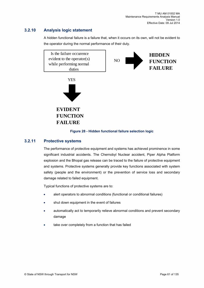
T MU AM 01002 MA Maintenance Requirements Analysis Manual
Version 1.0 Effective Date: 09 Jul 2014
© State of NSW through Transport for NSW Page 61 of 135
3.2.10 Analysis logic statement
A hidden functional failure is a failure that, when it occurs on its own, will not be evident to
the operator during the normal performance of their duty.
Figure 28 - Hidden functional failure selection logic
Is the failure occurence evident to the operator(s) while performing normal
duties
NO
YES
HIDDEN FUNCTION FAILURE
FAILURE
EVIDENT FUNCTION
3.2.11 Protective systems
The performance of protective equipment and systems has achieved prominence in some
significant industrial accidents. The Chernobyl Nuclear accident, Piper Alpha Platform
explosion and the Bhopal gas release can be traced to the failure of protective equipment
and systems. Protective systems generally provide key functions associated with system
safety (people and the environment) or the prevention of service loss and secondary
damage related to failed equipment.
Typical functions of protective systems are to:
alert operators to abnormal conditions (functional or conditional failures)
shut down equipment in the event of failures
automatically act to temporarily relieve abnormal conditions and prevent secondary
damage
take over completely from a function that has failed

T MU AM 01002 MA Maintenance Requirements Analysis Manual
Version 1.0 Effective Date: 09 Jul 2014
© State of NSW through Transport for NSW Page 62 of 135
There are two types of protective systems, monitored and unmonitored. Diagrammatic
examples of the two systems are shown in Figure 29. The maintenance response to
possible failures of each of these systems types is quite different:
monitored systems provide immediate notice of protective system failure and allow
two possible maintenance responses:
shut down the protected system until the protective elements have been
repaired
undertake a risk assessment to establish a maximum acceptable time for the
system to be non-operational and the repair process completed
unmonitored systems do not provide notice of failure and require the application of
a failure finding task. Again, risk analysis may be used to determine the necessary
period between the failure finding tasks which achieve an acceptable level of risk
exposure
Figure 29 - Examples of monitored and unmonitored protective systems
PROCESS
Unmonitored - Failed Sensor not evident
PROCESS
Dolls-eye Indicator Normally Off
Monitored - Failed Sensor
Sensor
Dolls-eye Indicator Normally On
Sensor

T MU AM 01002 MA Maintenance Requirements Analysis Manual
Version 1.0 Effective Date: 09 Jul 2014
© State of NSW through Transport for NSW Page 63 of 135
3.2.12 Use of risk assessment
Risk assessment involves the application of probability theory and reliability engineering
associated with event consequence calculations to determine quantitative values of risk.
The procedures for this are defined in the AS IEC 60300 suite of Dependability
Management standards (that is; 60300.1, 60300.2, and 60300.3) and AS/NZS ISO 31000
Risk Management.
In conclusion it must be remembered that in real life the vast majority of hidden functions
relate to protective devices which have random failure characteristics and are not fail
safe. Thus the application of some failure finding task at a frequency determined by risk
analysis is usually mandatory.
3.2.13 Suggested readings and references
The suggested additional readings for this section are listed below.
United States Military Standard MIL-STD-1629A / IEC 60812
Nowlan & Heap, Reliability-Centred Maintenance
United States Military Standard MIL-HDBK-2173(AS)
Moubray, RCMII Reliability-Centred Maintenance
Smith, Reliability-Centred Maintenance
AS IEC 60812-2008 – Analysis Techniques for System Reliability – Procedure for
Failure Mode and Effects Analysis (FMEA), ed. 2
MSG 3 Report
3.3 Criticality analysis
3.3.1 Introduction
The purpose of criticality analysis in FMECA and RCM is quite different. During design, it
is used to assist the designers in identifying failure modes which should or must be
removed, where in RCM it is used to determine the logic process for the analysis.
3.3.2 Criticality during design
The criticality assessment procedures in MIL-STD-162931 pp 102-1 to 102-7 are designed
to rank each potential failure mode identified in the Failure Modes and Effects Analysis
(FMEA) in accordance with its risk of the combined influence of failure severity and
probability of occurrence.
31 MIL-STD-1629, A Procedure For a Failure Mode, Effects, and Criticality Analysis

T MU AM 01002 MA Maintenance Requirements Analysis Manual
Version 1.0 Effective Date: 09 Jul 2014
© State of NSW through Transport for NSW Page 64 of 135
FMECA uses the criticality rating to prioritise potential failure modes in regard to their
criticality (probability of event multiplied by the consequence) and directs design
resources to removal of high criticality (risk) failure modes. The process is used during
initial design to prioritise effort to remove high risk failures by redesign.
During design, criticality analysis may be either qualitative or quantitative. The process is
directed at the early design stage where the risk associated with identified failure modes
are quantified, prioritised and assessed as to the effectiveness of compensating
provisions such as operator or maintenance action. High risk failure modes can then be
cost effectively removed in priority by design changes.
In undertaking the criticality analysis, the analyst shall identify how or even if the operator
is able to detect the failure, the compensating provisions applicable to mitigating the
effect of the failure, the severity of the failure, and the ‘criticality’ ranking. These factors
are described in more detail below.
Two approaches to criticality ranking are possible, a qualitative approach that assigns
coded descriptors against severity and frequency to establish a criticality matrix (see
Figure 1) and a quantitative approach which calculates the risk associated with each
identified failure mode. The results of the quantitative approach can also be
superimposed on the criticality matrix, which allows the criticality analysis process to be
applied both qualitatively and quantitatively depending upon the level of data available on
each failure mode.
4 3 2 1
A
B
C
D
E
Level
Probability
of
rrence
Severit
Increasing
Increasing
Occu
y Classification
Criticality
Increasing
Figure 30 - Typical Criticality matrix
a) Operator detection
The method by which occurrence of the failure mode is detected by the operator sh
recorded. The operator may be the train driver, train controller, signaller, electrical s
all be
ystem
operator or maintainer (on or offsite) depending upon the system and the current
operating mode.

T MU AM 01002 MA Maintenance Requirements Analysis Manual
Version 1.0 Effective Date: 09 Jul 2014
© State of NSW through Transport for NSW Page 65 of 135
The failure detection means is to be identified. This shall include methods such as visual
or audible warning devices, automatic sensing devices, sensing instrumentation, other
unique indications, or none at all. Where the warning takes the form of a degradation of
condition that is managed by a maintenance intervention / exam
of operator indication would be nil.
Other indications
Descriptions of indications which are evident to an oper
malfunctioned or failed, other than the identified warning de
Proper correlation of a system malfunction or failure may requi
indications as well as abnormal indications. If the undetected fa
remain in a safe state, a second failure situation should be expl
or not an indication will be evident to the operator. Indication
described as shown below:
Normal – An indication that is evident to an operator when th
operating normally.
Abnormal – An indication that is evident to an operator
malfunctioned or failed.
Incorrect – An erroneous indication to an operator due to the
indicator (i.e., instruments, sensing devices, visual or audible wa
Isolation
Describe the most direct procedure that allows an operator to
failure. An operator will know only the initial symptoms until furth
ination type task, the type
ator that a system has
vices, shall be recorded.
re identification of normal
ilure allows the system to
ored to determine whether
s to the operator shall be
e system or equipment is
when the system has
malfunction or failure of an
rning devices, etc.).
isolate the malfunction or
er specific action is taken
such as a maintainer performing a more detailed built-in-test (BIT). The failure being
considered in the analysis may be of lesser importance or likelihood than another failure
that could produce the same symptoms and this must be considered.
Fault isolation procedures require a specific action or series of actions by an operator,
followed by a check or cross reference either to monitoring system VDUs, instruments,
control devices, circuit breakers, or combinations thereof. This procedure is followed until
a satisfactory course of action is determined.

T MU AM 01002 MA Maintenance Requirements Analysis Manual
Version 1.0 Effective Date: 09 Jul 2014
b) Compensating provision
An important element of the FMECA is the identification of compensating provisions
which will nullify the effects of a malfunction or failure. Identification of these provisions
enable the true behaviour of an item in its operating context to be determined and could
include:
Design
Compensating provisions which are features of the design at any level that will nullify the
effects of a malfunction or failure, control, or deactivate system items to halt generation or
propagation of failure effects, or activate backup or standby items or systems shall be
described. Design compensating provisions include:
redundant items that allow continued and safe operation
safety or relief devices such as monitoring or alarm provisions which permit
effective operation or limit damage
alternative modes of operation such as backup or standby items or systems
fail safe designs which may fail in a manner which interrupts service rather than in
a safety critical manner (see 3.3.4)
Operator action
Compensating provisions which require operator action to circumvent or mitigate the
effect of the failure shall be described. The compensating provision that best satisfies the
indication observed by an operator when the failure occurs shall be determined. This may
require the investigation of an interface system to determine the most correct operator
action. The consequences of any probable incorrect action by the operator in response to
an abnormal indication should be considered and the effects recorded.
Maintenance
Compensating provisions which require maintenance action to manage the postulated
failure relate to those failure modes which can be successfully managed by maintenance
tasks such as lube/service, condition monitoring/assessment, scheduled restoration /
discard, or failure finding (i.e. operational check) type actions. If this compensating
provision is selected the task and associated task effectiveness and task interval shall be
supported with an RCM analysis.
© State of NSW through Transport for NSW Page 66 of 135

T MU AM 01002 MA Maintenance Requirements Analysis Manual
Version 1.0 Effective Date: 09 Jul 2014
Commissioning test
Compensating provisions which require commissioning tests as a compensating
provision are aligned to those failure modes, which once verified cannot change until
such time as the equipment is replaced / recommissioned. Tests of this nature are
typically polarity tests for power supplies and dc magnetically held high current high
speed circuit breakers.
c) Severity class
A severity classification category shall be assigned to each failure mode according to the
failure effects. The effect on the functional condition of the item under analysis caused by
the loss or degradation of output shall be identified so the failure mode effect will be
properly categorised.
Where effects on higher levels are unknown, a failure’s effect on the level under analysis
shall be described by the severity classification categories.
Severity classifications are assigned to provide a qualitative measure of the worst
potential consequences resulting from design error or item failure. A severity
classification shall be assigned to each identified failure mode in each item analysed in
accordance with the loss statements below.
Where it may not be possible to identify an item or failure mode according to the loss
statements in the four categories below, similar loss statements based upon loss of
system inputs or outputs shall be developed and included in the FMECA ground rules for
procuring activity approval.
Severity classification categories for application in the NSW rail environment are defined
as follows:
category 1 - catastrophic - A failure which may cause death and/or multiple
severe injury, or extensive interruption of train-services
category 2 - critical - A failure which may cause severe injury, major property
damage, major system damage or which will result in interruption to train-services
greater than 15 minutes
category 3 - marginal - A failure which may cause minor injury, minor property
damage, minor system damage or which will result in minor train delays (3-15
minutes) delay or loss of availability
category 4 - minor - A failure not serious enough to cause injury, property
damage, system damage or train delays, but which will result in unscheduled
maintenance or repair
© State of NSW through Transport for NSW Page 67 of 135

T MU AM 01002 MA Maintenance Requirements Analysis Manual
Version 1.0 Effective Date: 09 Jul 2014
The failure effect severity shall also be qualitatively classified against the four categories
of Evident (i.e. not Hidden mode failure), Safety, Environmental and Operational. See
Section 3.3.3
d) Criticality analysis
The criticality analysis within the design FMECA process is intended to provide a
methodology whereby all failure modes are ranked with the aim of determining the
relativity of various failure modes, and subsequently identifying potential candidate failure
modes for redesign. The ranking is achieved by determining the relative probability of
each failure mode using either a qualitative or a quantitative basis.
The failure mode’s criticalities are calculated for each failure mode, and then summed to
provide a part criticality which is used for the final sorting. As a check that the failure
modes for each part identified in the FMEA have been considered by the analysis team,
each failure mode is allocated a relative weighting within the part. This weighting - the
failure mode Ratio (α), is allocated by the analysis team to each failure mode and the
sum of these within each part should add up to 1.0. A check can be automatically
provided for each part on the maintenance requirement analysis system data entry table,
and the sum highlighted when it is not equal to 1.0.
© State of NSW through Transport for NSW Page 68 of 135
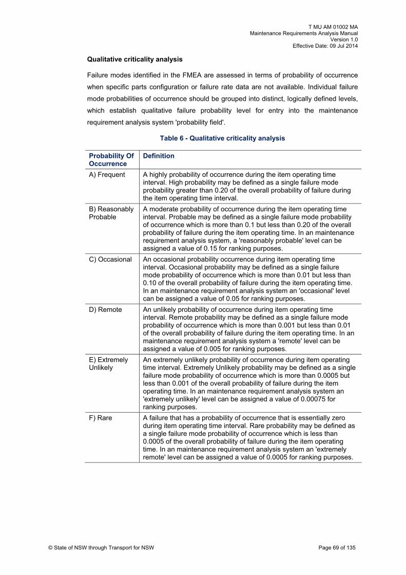
T MU AM 01002 MA Maintenance Requirements Analysis Manual
Version 1.0 Effective Date: 09 Jul 2014
© State of NSW through Transport for NSW Page 69 of 135
Qualitative criticality analysis
Failure modes identified in the FMEA are assessed in terms of probability of occurrence
when specific parts configuration or failure rate data are not available. Individual failure
mode probabilities of occurrence should be grouped into distinct, logically defined levels,
which establish qualitative failure probability level for entry into the maintenance
requirement analysis system 'probability field'.
Table 6 - Qualitative criticality analysis
Probability Of Occurrence
Definition
A) Frequent A highly probability of occurrence during the item operating time interval. High probability may be defined as a single failure mode probability greater than 0.20 of the overall probability of failure during the item operating time interval.
B) Reasonably Probable
A moderate probability of occurrence during the item operating time interval. Probable may be defined as a single failure mode probability of occurrence which is more than 0.1 but less than 0.20 of the overall probability of failure during the item operating time. In an maintenance requirement analysis system, a 'reasonably probable' level can be assigned a value of 0.15 for ranking purposes.
C) Occasional An occasional probability occurrence during item operating time interval. Occasional probability may be defined as a single failure mode probability of occurrence which is more than 0.01 but less than 0.10 of the overall probability of failure during the item operating time. In an maintenance requirement analysis system an 'occasional' level can be assigned a value of 0.05 for ranking purposes.
D) Remote An unlikely probability of occurrence during item operating time interval. Remote probability may be defined as a single failure mode probability of occurrence which is more than 0.001 but less than 0.01 of the overall probability of failure during the item operating time. In an maintenance requirement analysis system a 'remote' level can be assigned a value of 0.005 for ranking purposes.
E) Extremely Unlikely
An extremely unlikely probability of occurrence during item operating time interval. Extremely Unlikely probability may be defined as a single failure mode probability of occurrence which is more than 0.0005 but less than 0.001 of the overall probability of failure during the item operating time. In an maintenance requirement analysis system an 'extremely unlikely' level can be assigned a value of 0.00075 for ranking purposes.
F) Rare A failure that has a probability of occurrence that is essentially zero during item operating time interval. Rare probability may be defined as a single failure mode probability of occurrence which is less than 0.0005 of the overall probability of failure during the item operating time. In an maintenance requirement analysis system an 'extremely remote' level can be assigned a value of 0.0005 for ranking purposes.

T MU AM 01002 MA Maintenance Requirements Analysis Manual
Version 1.0 Effective Date: 09 Jul 2014
© State of NSW through Transport for NSW Page 70 of 135
Quantitative Criticality Analysis Calculation
The quantitative criticality analysis is formed by calculating the individual failure mode
criticality Cm = β α λ t (See below for definitions). The failure criticality of the higher level
part is then calculated from the sum of its failure mode criticalities (Cm).
A FMECA criticality report can then be produced, which reports the part criticalities in
descending order within each of the four criticality groups, evident, Safety, Environmental
and Operational. This report assists the design team in identifying parts with the
system/equipment which have unacceptable criticalities and which are logical candidate
items for redesign.
Failure Mode Ratio - α
The fraction of the part failure rate (λp) related to the particular failure mode under
consideration shall be evaluated by the analysis team and recorded. The failure mode
ratio is the probability expressed as a decimal fraction that the part or item will fail in the
identified mode. If all potential failure modes of a particular part or item are listed, the sum
of the α values for that part or item will equal one. If detailed failure mode data is not
available, the α values shall represent the analyst’s judgement based upon all analysis of
the item’s functions.
Part Failure rates - λ
The failure rates are included in the quantitative analysis method. The analysis team
identifies the Conditional Failure Rate and the Functional Failure Rate. The rates are
identified in terms of failures per year and are summed into a Design Failure Rate. Where
the data is available as gross failure rate value, the analysis team shall apportion the
rates between the conditional and functional failure rates. These apportioned rates shall
then form the basis against which the actual failure rate performance can be monitored
and compared when the system becomes operational.
Operating time - t
This is the operating time in years over which the criticality ranking is to be performed.
Generally this would be over one year.
Failure effect probability - β
The β values are the conditional probability that the failure’s System Effect will result in
the criticality classification with the identified severity once the failure mode has occurred.
The β values should reflect the analysis team’s judgement where actual data is not
available, and be quantified according to Table 7.

T MU AM 01002 MA Maintenance Requirements Analysis Manual
Version 1.0 Effective Date: 09 Jul 2014
© State of NSW through Transport for NSW Page 71 of 135
Table 7 – Failure effect and β values
Failure Effect β value
Actual loss 1.00
Probable loss >0.1~ to <1.00
Possible loss >0 to 0.10
No effect 0
Sample failure mode criticality calculation
Quantitative Method
Failure Mode 1: α = 0.1, β = 0.25, λp = .25 failures per year, t = 1 year
Cm1 = 0.00625
Failure Mode 2: α = 0.9, β = 0.1, λp = .25 failures per year, t = 1 year
Cm2 = 0.0225
Cpart = Cm1+ Cm2 = 0.02875
Qualitative Method
This could also have been estimated qualitatively by selecting the Remote probability for
the first failure mode, and the Occasional probability for the second failure mode, which
would have resulting in a similar ranking of overall part criticality.

T MU AM 01002 MA Maintenance Requirements Analysis Manual
Version 1.0 Effective Date: 09 Jul 2014
© State of NSW through Transport for NSW Page 72 of 135
3.3.3 During maintenance analysis
RCM analysis uses criticality to determine the analysis logic through a broad division of
possible failure effects (adverse outcomes) into two by two matrix of combining failure
visibility (hidden and evident) and failure effect (safety/environment and economic).
Figure 31 describes the four resulting categories.
HIDDEN EVIDENT
ENT 1SAFETY/
ENVIRONM
2ECONOMIC
3
4
Figure 31 - Four criticality groupings
HIDDEN / SAFETY/ENVIRONMENT
HIDDEN / ECONOMIC
(EVIDENT) SAFETY/ENVIRONMENT
(EVIDENT) ECONOMIC
Effects such as 'service or operations' have been used to give priority to unquantifiable
economic loss flowing from in-service failures. This is generally not supported as it avoids
the issue of properly accounting for failure effects. The baseline comparison of all non-
statutory (other than safety and environment) outcomes is encouraged to support a
business approach using economic cost as a comparison.
RCM analysis applies a logic flow using only broad divisions of criticality. These criticality
assessments then direct the analyst into a particular logic process as described in
Section 4.1. The logic process for selecting failure mode criticality is shown in Figure 32.
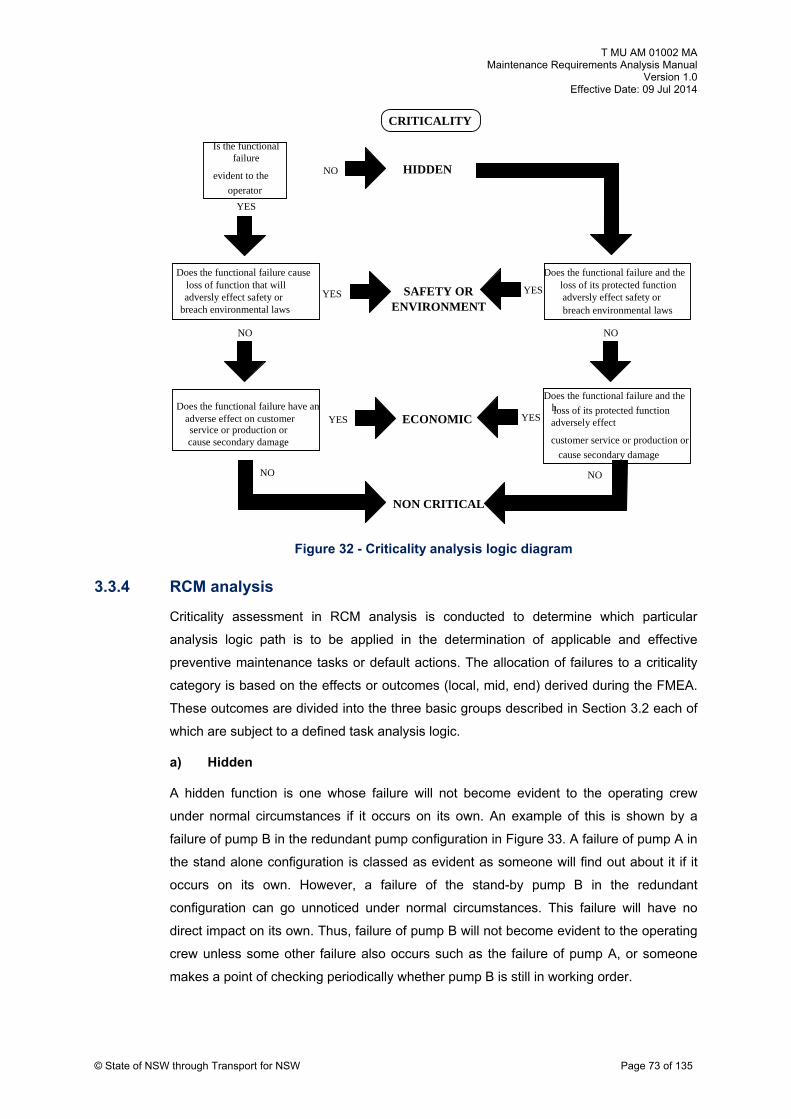
T MU AM 01002 MA Maintenance Requirements Analysis Manual
Version 1.0 Effective Date: 09 Jul 2014
© State of NSW through Transport for NSW Page 73 of 135
Figure 32 - Criticality analysis logic diagram
Is the functional failure
evident to the
operator
NO
YES
HIDDEN
C
Does the functional failure have an adverse effect on customer service or production or
YES
NO
Does the functional failure cause loss of function that will adversly effect safety or
breach environmental laws
YES
NO
ECONOMIC
SAFETY OR ENVIRONMENT
RITICALITY
cause secondary damage
Does the functional failure and the loss of its protected function adversly effect safety or breach environmental laws
YES
YES
NO
loss of its protected function adversely effect
customer service or production or
cause secondary damage
NON CRITICAL
NO
Does the functional failure and the h
3.3.4 RCM analysis
Criticality assessment in RCM analysis is conducted to determine which particular
analysis logic path is to be applied in the determination of applicable and effective
preventive maintenance tasks or default actions. The allocation of failures to a criticality
category is based on the effects or outcomes (local, mid, end) derived during the FMEA.
These outcomes are divided into the three basic groups describ
which are subject to a defined task analysis logic.
a) Hidden
A hidden function is one whose failure will not become evide
under normal circumstances if it occurs on its own. An examp
failure of pump B in the redundant pump configuration in Figure
the stand alone configuration is classed as evident as someon
occurs on its own. However, a failure of the stand-by pu
configuration can go unnoticed under normal circumstances.
direct impact on its own. Thus, failure of pump B will not becom
ed in Section 3.2 each of
nt to the operating crew
le of this is shown by a
33. A failure of pump A in
e will find out about it if it
mp B in the redundant
This failure will have no
e evident to the operating
crew unless some other failure also occurs such as the failure of pump A, or someone
makes a point of checking periodically whether pump B is still in working order.

T MU AM 01002 MA Maintenance Requirements Analysis Manual
Version 1.0 Effective Date: 09 Jul 2014
© State of NSW through Transport for NSW Page 74 of 135
A
B
A
Configuration 1 - Stand Alone
Configuration 2 - Redundant Standby
Figure 33 - Operating configurations
Hidden failures can be separated from evident failures by asking 'will the loss of function
caused by this failure mode become evident to the operating crew or staff under normal
circumstances?'
If the answer to this question is no, the failure mode is hidden, and if the answer is yes, it
is evident.
In general the vast majority of hidden functions are protective equipment that are not fail-
safe (See Section 3.2.9). The function of this equipment is to ensure that the
consequences of the failure of the protected function is significantly less than if there
were no protection. So any protective device is in fact part of a sys
components:
the protective equipment
the protected function.
Fail-safe protective equipment
tem with at least two

T MU AM 01002 MA Maintenance Requirements Analysis Manual
Version 1.0 Effective Date: 09 Jul 2014
© State of NSW through Transport for NSW Page 75 of 135
In this context fail-safe means that the failure of the device on its own will become evident
to the operating crew under normal circumstances. This is because fail-safe units usually
stop the system from operating if there is a failure. Railway signalling is an example of a
fail-safe system where the system signals the driver with a red stop in the event of a
critical failure. Another is a HZ circuit breaker trip circuit supervision system which raises
an alarm signal to the electrical system operator in the event of a critical failure of the
circuit breaker’s trip circuit.
Fail-safe systems in power stations use parallel sensors whose output is constantly
monitored by a software comparator in the receiving circuit board which sends a warning
to the operator if there is a variation between the signals.
Protective equipment which are not fail-safe
In a system which contains a protective device which is not fail-safe, the fact that the
device is unable to fulfil its intended function will not be evident to the operator under
normal circumstances.
There are considered to be two categories of hidden functions which are not fail-safe:
the protective system is a standby to a primary function and gives no indication that
it is in a failed state (passive hidden function).
the protective system is required to measure and assess (continually active)
whether a particular event has occurred and act in some manner to protect the
system but is in a failed state with no indication (active hidden function).
b) Safety/environment
Safety and environmental requirements are statutory (i.e. covered by Acts of Parliament
and associated government regulations). This category of failures is defined as that
where a failure mode has:
safety consequences if it causes a loss of function or other damage which could
injure or kill someone
environmental consequences if it causes a loss of function or other damage which
could lead to the breach of any known environmental standard or regulation
c) Economic
The consequences of an evident failure which has no direct adverse effect on safety or
the environment are classified as economic as all outcomes can be costed in some
manner.

T MU AM 01002 MA Maintenance Requirements Analysis Manual
Version 1.0 Effective Date: 09 Jul 2014
© State of NSW through Transport for NSW Page 76 of 135
Economic consequences comprise all failure consequences that incur a financial loss that
is probabilistic in nature. This loss may be direct cost against the balance sheet or
indirect in terms of image loss or customer perception that will require financial
expenditure to recover. Some possible economic consequences flowing from a possible
failure mode are listed at Table 8.
Table 8 - Failure mode economic consequences
Event Probability Consequence
Repair 1 Average cost of repairs
Secondary damage Variable Average cost of repairs
Service loss Variable Value of foregone revenue either immediate due vel or customer loss cancelled tra
Image loss Variable Cost of advertising necessary to repair an established image
Fines Variable Direct penalties for statutory breaches plus cost of defence plus possible loss of image costs
Compensation Variable Direct penalties plus possible loss of image costs
Insurance premiums Variable Increased cost of premiums associated with insured element of loss
For failure modes with economic consequences:
a preventive task is worth doing (effective) if over a period of time, it costs less than
the cost of the consequences of the failures which it is meant to prevent
Assessing the effectiveness of a task is achieved by summing the probabilistic economic
cost of failures and comparing the result to the cost of preventive maintenance.
If a repetitive preventive task is not worth doing, then in rare cases a modification may be
justified as a single one-off cost.
3.3.5 Suggested readings and references
The suggested additional readings for this section are listed below.
United States Military Standard MIL-STD-1629A / IEC 60812
Nowlan & Heap, Reliability-Centred Maintenance
United States Military Standard MIL-HDBK-2173(AS)
Moubray, RCMII, Reliability-Centred Maintenance
Smith, Reliability-Centred Maintenance
AS IEC 60812-2008 – Analysis Techniques for System Reliability – Procedure for
Failure Mode and Effects Analysis (FMEA), ed. 2
MSG 3 Report

T MU AM 01002 MA Maintenance Requirements Analysis Manual
Version 1.0 Effective Date: 09 Jul 2014
© State of NSW through Transport for NSW Page 77 of 135
4. RCM analysis
4.1 Task analysis
Every failure has an impact on an organisations ability to service its internal and external
customers. Some failures are directly related to product via their effect on output and
quality, others relate to external factors such as adverse public safety and environmental
effects. Some failures have no immediate effect but lower system reliability established
by the designer via the use of redundancy provisions or monitoring functions associated
with human intervention.
Preventive maintenance tasks are identified and established to reduce the adverse
impacts of failures. These failures consume resources to correct and often result in loss
of revenue from reduced product or service supply. It may also result in significant losses
through personal injury and secondary damage. The effort organisations will apply to
prevent failures is usually a function of the consequence of failures; high impact failures
will generate considerable effort to prevent, while low consequence failures may result in
a purely reactive effort.
Having identified the failure modes relevant to the equipment in its operating
environment, the task analyst must identify two quite different sets of maintenance tasks
depending on the stage in the equipment's life cycle. For new acquisition projects (i.e.
analysis undertaken during the design phase) the analyst must identify all maintenance
tasks identified as a consequence of failures. This will include both corrective and
preventive tasks, a list of which provides the technical manuals writer with the raw
material for the engineering publications which support the equipment.
4.1.1 Task objectives
Failure prevention is not so much about preventing the failures themselves but avoiding
or reducing the consequences i.e. risk reduction where:
risk = probability of failure x consequence of failure
"Failure prevention has much more to do with avoiding or reducing the consequences of
failure than it has to do with preventing the failures themselves."32
Thus preventive action must be directed at reducing both the probability of the failure and
the consequence of the failure.
"A preventive task is worth doing if it deals successfully with the consequences of the
failure which it is meant to prevent"33
32 Moubray, John, Reliability-Centred Maintenance, Butterworth Heinemann, 1992 33 Moubray, 1992, Op Cit.

T MU AM 01002 MA Maintenance Requirements Analysis Manual
Version 1.0 Effective Date: 09 Jul 2014
© State of NSW through Transport for NSW Page 78 of 135
4.1.2 Task options
The task types applied through RCM fall into four outcome categories:
life extending tasks where the item is serviced or lubricated to achieve its inherent
design life
failure preventing tasks where the item is either repaired in situ or removed from
service prior to functional failure to prevent the consequences of such a failure.
failure finding tasks which identify hidden failures to reduce the risk of double
failure to acceptable levels.
default tasks that determine necessary action if the consequences of failures
cannot be managed by maintenance alone.
Thus life extending tasks ensure that the inherent design life of the equipment is achieved
by ensuring design requirements, commensurate with the operating environment, are
complied with. Life extending tasks do not however manage the consequences of failure
and must be associated with a failure management task to reduce the failure risk.
Failure preventing and finding tasks manage the risk of failure by reducing the failure
probability to an acceptable level commensurate with the inherent design characteristics
of the equipment.
Default tasks such as redesign manage the problem of no effective maintenance to
manage the failure mode.
The preventive maintenance task options available to the analyst are:
lubrication/service task that includes lubrication (generally a design requirement)
or consumables replenishment as with fuel and oil
condition monitoring task which detects conditional (potential) failures before
they lead to functional failure and allow the equipment to be either repaired in situ
or replaced and a restoration process conducted at a separate facility. Note that
calibration tasks are considered to be condition monitoring tasks
scheduled restoration or rework which at some hard time conducts a standard
schedule of maintenance tasks on an item of equipment
scheduled discard which at some hard time removes an item from the system
and discards either the item or some element of it such as an electrolytic capacitor
combination task which may combine a number of the above task types which
individually may not be effective against the identified failure mode

T MU AM 01002 MA Maintenance Requirements Analysis Manual
Version 1.0 Effective Date: 09 Jul 2014
© State of NSW through Transport for NSW Page 79 of 135
failure finding task which is only applicable to hidden functional failures where a
confidence check that the system is still operational is required at some interval to
reduce the probability of double failures
default task which provides for situations where an effective preventive
maintenance task cannot be identified
An additional maintenance activity which is not specifically determined by the RCM
analysis logic is the tonal examination. This examination consists of a general look at an
area without necessarily a specific examine task and is a confidence building task
undertaken on items which:
are subject to very slow inherent rates of degradation that may lead to significant
consequences if left unattended indefinitely
may go lengthy periods without a site visit and which are exposed to random
external activity such as vandalism or environmental damage
4.1.3 Task applicability
The RCM analysis logic diagrams shown at Figure 35 to Figure 38 (with an overview
shown in Figure 40) that guides the analyst through the process of selecting tasks which
are applicable (technically feasible) and effective (worth doing). This means that the task
must address the failure mode by reducing its probability of occurrence and must reduce
that probability to an acceptable level commensurate with the cost of the task.
The process of selecting tasks which are applicable firstly identifies a listing of possible
tasks. These tasks represent various maintenance strategies as follows:
Service/lubrication. Service tasks replenish material consumed during the normal
operation of the equipment; examples of this include grease in trackside
lubricators, greasing linkages, oil change/replacement, and water and detergent in
windscreen washers. In addition, lubrication tasks which renew degraded or
removed lubricant material are usually the mandatory requirement of a design and
must be included in the program. (Refer to Section 4.1.3a).
On condition. These tasks prevent potential failures before they can cause a
functional failure. The tasks include examinations for indications of conditional
degradation commensurate with an unacceptable increase in failure probability.
There are four criteria for on condition task applicability:
it must be possible to detect the reduced resistance to failure for a particular
engineering failure mode.
it must be possible to define a potential failure condition that can be detected
by an explicit task.

T MU AM 01002 MA Maintenance Requirements Analysis Manual
Version 1.0 Effective Date: 09 Jul 2014
© State of NSW through Transport for NSW Page 80 of 135
there must be a reasonably consistent time interval between the potential to
identify the (conditional) failure and the functional failure.
near original reliability performance is restored.
Hard time rework or discard. These are tasks which schedule either a rework
(overhaul) task or a throw away (discard) task at a fixed period or number of events
because their function is considered so critical that no failures can be acceptable.
An example of these is the discard of the front fan of a high ratio by-pass gas
turbine engine which has a known fatigue life with a high consequence outcome.
The applicability criteria are:
the item must be capable of achieving an acceptable level of restored failure
resistance through a rework task
the item must exhibit wear-out characteristics which are identified by a rapid
increase in the conditional probability of failure such that a wear out age for
reworks or a safe life limit for discard can be established
a large percentage of the items must survive to the wear out age or life limit
Failure finding. The task must be applicable to the hidden failure and would
usually follow the form of an operational or functional check (see definitions) task to
determine the current status of the equipment.
A list of these task options, their task outcome category, the selection sequencing and
relationships is shown at Figure 34. Depending on the RCM criticality assigned to the
failure mode, a selection of possible tasks in order of cost is presented for assessment as
to their applicability and effectiveness.
Tasks to be selected must be both applicable to the failure cause and effective in
managing the failure risk. Should there be no effective failure management mechanism
then the default task shall apply.
Once an applicable and effective task has been identified then the analyst stops as any
further task will increase costs dramatically for little additional reduction in failure risk.
a) Service / lubrication task application using an maintenance requirement
analysis system
In maintenance requirement analysis system, the service/lubrication tasks can be
determined as part of the task selection process directed at specific failure modes.
34Nowlan and Heap proposes that:
34 Nowlan and Heap, Reliability-Centred Maintenance, US Department of Commerce, National Technical Information Service,
December 1978, p 72, sec. 3.6.

T MU AM 01002 MA Maintenance Requirements Analysis Manual
Version 1.0 Effective Date: 09 Jul 2014
© State of NSW through Transport for NSW Page 81 of 135
“lubrication for example, really constitutes scheduled discard of a single celled item
(the old lubrication film). This task is applicable because the film does deteriorate
with operating age and shows wear out characteristics.”
and
“the servicing tasks (e.g. checking fluid levels in oil or hydraulic systems) are on-
condition tasks. In this case, potential failures are represented by pressure or fluid
levels below the replenishment level, and this condition is corrected in each unit as
necessary.”
Using this concept, lubrication and servicing tasks are identified as ‘Consequence
Preventing’ (Refer to Figure 34) when applying the task selection processes shown in
Section 4.1.8.
Thus the selection of an applicable and effective lubrication task in an maintenance
requirement analysis system constitutes the scheduled discard of the old lubrication film.
Similarly the selection of an applicable and effective servicing task in an maintenance
requirement analysis system constitutes the examination for indications of conditional
degradation of the oil (e.g. condition monitoring of the oil level / level of contamination).
Table 9 - Examples
System under analysis: ACCB System under analysis: Air Compressor Subsystem (Part of ACCB)
Part Description #1 Air Compressor Part Description #1 Oil
Failure Description #A
Seizes Failure Description #A Degrades
Failure Cause #1 Proposed task
Oil degradation Replace oil every 2 years.
Failure Cause #1 Proposed task
Operational use Replace oil every 2 years.
Failure Description #B Leaks
Failure Cause #2 Proposed task
Oil leakage from life expired seals Examine seals and check oil level
Failure Cause #1 Proposed task
Oil seals life expired Examine seals and check oil level
Failure Description #C Depleted
Failure Cause #3 Proposed task
Normal oil operational consumption Check oil level
Failure Cause #1 Proposed task
Normal oil operational consumption Check oil level
Failure Cause #4 Proposed task
Oil contaminated from operational use Replace oil after 1000 operations
Failure Cause #2 Proposed task
System leaks Examine for leaks and Check oil level

T MU AM 01002 MA Maintenance Requirements Analysis Manual
Version 1.0 Effective Date: 09 Jul 2014
r analysis: ACCB System unde System under analysis: Air Compressor Subsystem (Part of ACCB)
Failure Description #D Contaminated
Failure Cause #1 Normal operational use
Proposed task Replace oil after 1000 operations
Table 9 shows the same equipment, the ‘Air Compressor’, being analysed in two ways.
Under the 'System: ACCB' analysis, the ‘air compressor’ is analysed as a part, which if it
fails, would impact on the function of the system and have some failure consequences.
The compressor would be a configuration item for the ACCB. At this level, the oil is not
considered as a configuration item.
Under the 'System: Air Compressor System' analysis, the air compressor is analysed as a
system and the oil is analysed as a part. The oil is considered as a configuration item
for the compressor as it forms an integral part of the design of the system. The oil,
if it fails, would impact on the function of the system and have some failure
consequences.
In both cases, the identification and structure of the failure mode (identifying the root
cause) provided a task for each specific failure mode.
4.1.4 Task effectiveness
The task effectiveness criteria is applied on the basis of the required outcomes of the task
which flow directly from the failure consequences. These effectiveness criteria relate
directly to consequence and are as follows:
Hidden function. Preventive maintenance tasks are worth doing if they reduce the
risk of double failures to an acceptable level.
Safety and environment. Preventive tasks are worth doing if they reduce the risk
of failure to an acceptable level.
Economics. Preventive tasks are worth doing if the cost of doing the tasks is less
than the cost of not doing the tasks, that is; the cost of operational failures and/or
the cost of repairing the items after failure.
© State of NSW through Transport for NSW Page 82 of 135

T MU AM 01002 MA Maintenance Requirements Analysis Manual
Version 1.0 Effective Date: 09 Jul 2014
© State of NSW through Transport for NSW Page 83 of 135
4.1.5 Non-programmed tasks
Assets that are exposed to the public in generally insecure situations can suffer from
various degrees of damage due to either vandalism or accidents. Those actions that
result in the immediate loss of a function that is operator monitored have no effective
preventive maintenance tasks and would not be included in the maintenance program.
However, some forms of damage can either inflict hidden function failure or significantly
reduce resistance to failure.
Exposures to random failure from reduced failure resistance through vandalism or
accident must be managed by inclusion in the appropriate condition monitoring or failure
finding program even though not strictly an RCM logic task. These tasks are often
included within the zonal examination programs as they are random in nature and
cannot usually be clearly defined by a specific task in the servicing schedule.
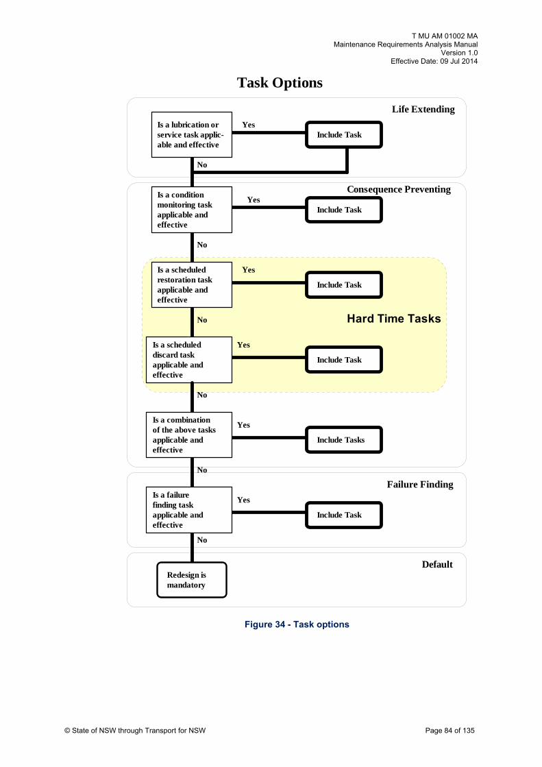
T MU AM 01002 MA Maintenance Requirements Analysis Manual
Version 1.0 Effective Date: 09 Jul 2014
© State of NSW through Transport for NSW Page 84 of 135
Figure 34 - Task options
Task Options
Is a lubrication orservice task applic-able and effective
Is a condition monitoring taskapplicable andeffective
Is a scheduled
YesInclude Task
Include TaskYes
No
No
Life Extending
restoration taskapplicable andeffective
Is a scheduleddiscard taskapplicable andeffective
No
Redesign ismandatory
No
Yes
Yes
Include Task
Include Task
Is a failurefinding taskapplicable andeffective
No
Yes
Include Task
No
Is a combinationof the above tasksapplicable andeffective
Yes
Include Tasks
Consequence Preventing
Failure Finding
Default
Hard Time Tasks

T MU AM 01002 MA Maintenance Requirements Analysis Manual
Version 1.0 Effective Date: 09 Jul 2014
© State of NSW through Transport for NSW Page 85 of 135
4.1.6 Task logic charts
The basic logic diagram for conducting maintenance requirements analysis is provided at
Figure 13. The task analysis logic diagrams appropriate for each of the four criticality
categories, as represented by the shaded area in Figure 13, step the analyst through a
question and answer process to determine which of a set of possible maintenance
activities are applicable and effective for the equipment and its associated failure
mechanism.
For each identified consequence criticality there is a separate logic process for selecting
the appropriate preventive maintenance tasks. These lower order logic processes
following on from the selection of RCM criticality are shown in Figure 35 to Figure 38.
Analysts should note that the general practice is that once an effective task is found the
analysis process is discontinued. This is logical as to pursue the remaining few percent of
remaining unreliability with increasingly expensive maintenance processes would not
possibly be cost effective.
4.1.7 Default actions and tasks
Default strategies are necessary both during and at the end of the analysis logic. In new
systems where information is scarce decisions are required under conditions of
uncertainty. A decision default strategy allows decisions to be made under such
conditions.
4.1.8 Default decision strategy
The default decision strategy is listed at Table 10.
Table 10 - Default decision strategy checklist
Default decision Default answer
Possible adverse outcomes
Outcome eliminated with age exploration
Is item clearly non-significant?
No Unnecessary analysis No
Is the failure operator monitored?
No Unnecessary maintenance task
Yes
Does failure have safety impacts
Yes Unnecessary redesign or maintenance
No (redesign) Yes (maintenance)
Will condition monitoring task detect potential failures?
Yes Maintenance not cost effective
Yes
Is condition monitoring task effective?
Yes effective
Yes Maintenance not cost
Is hard time task applicable?
No Delayed opportunity to save costs
Yes
Is hard time task effective?
No Delayed opportunity to save costs
Yes

T MU AM 01002 MA Maintenance Requirements Analysis Manual
Version 1.0 Effective Date: 09 Jul 2014
© State of NSW through Transport for NSW Page 86 of 135
Figure 35 - Hidden function task analysis

T MU AM 01002 MA Maintenance Requirements Analysis Manual
Version 1.0 Effective Date: 09 Jul 2014
© State of NSW through Transport for NSW Page 87 of 135
Figure 36 - Safety and environmental task analysis

T MU AM 01002 MA Maintenance Requirements Analysis Manual
Version 1.0 Effective Date: 09 Jul 2014
© State of NSW through Transport for NSW Page 88 of 135
Figure 37 - Hidden economic task analysis

T MU AM 01002 MA Maintenance Requirements Analysis Manual
Version 1.0 Effective Date: 09 Jul 2014
© State of NSW through Transport for NSW Page 89 of 135
Figure 38 - Economic task analysis

T MU AM 01002 MA Maintenance Requirements Analysis Manual
Version 1.0 Effective Date: 09 Jul 2014
© State of NSW through Transport for NSW Page 90 of 135
4.1.9 Default tasks
As previously stated, depending on the consequences of failure, if a suitable (applicable
and effective) preventive maintenance task cannot be found then some default action
must be applied. The default tasks that have been defined for the four logic processes
associated with each assessed system or item criticality type are shown in Figure 35 to
Figure 38.
The application of default tasks usually means some form of redesign. This could take a
variety of forms from modifying the equipment to provide increased redundancy to
providing additional alert devices for the operators. These options are detailed in Smith35,
pages 147–154.
Figure 39 - Default logic chart
Yes
ECONOMICSAFETY AND
ENVIRONMENTHIDDEN
FUNCTION
Maintenance actionsreduce the probability of a
multiple failure to anacceptable level
Maintenance actions cost
from better operations
No
Redesign maybe DESIRABLE
Could the double failureadversely effect Safetyor the Environment?
No
Maintenance actionsreduce the probability of a
double failure to anacceptable level
Redesign isMANDATORY
Yes
No scheduledmaintenance
Redesign maybe DESIRABLE
No
more than the savings
&/or reduced repairs
Redesign isMANDATORY
4.1.10 Documentation of task decisions
The collective decision process which is undertaken in developing task lists may involve
keen discussion on the part of the analysts. Care should be taken to document the results
of these discussions in a manner that will enable later audits, reviewers or just seekers of
information to clearly see why the decision shown on the analysis form was reached.
For future staff attempting to improve the maintenance process, nothing could be worse
than cryptic, unsupported decisions regarding task selection or frequency. They will
probably need to start the analysis process again losing the value of many hours of hard
work by the original analysis team in data collection and argument.
35 Smith, Reliability-Centred Maintenance, McGraw-Hill, 1991

T MU AM 01002 MA Maintenance Requirements Analysis Manual
Version 1.0 Effective Date: 09 Jul 2014
© State of NSW through Transport for NSW Page 91 of 135
4.1.11 Summary
Figure 40 provides a summary of the relationship between:
failure consequences (RCM criticality)
task types
effectiveness criteria
applicability criteria
The diagram is meant to provide a single reference document to assist analysts in the
determination of applicability and effectiveness rules for tasks.
4.1.12 Suggested readings and references
Suggested additional readings for this section are listed below.
Nowlan & Heap, Reliability-Centred Maintenance
United States Military Standard MIL-HDBK-2173(AS)
Moubray, RCMII Reliability-Centred Maintenance
Smith, Reliability-Centred Maintenance
MSG 3 Report

T MU AM
E
01002 M Requirements Analysis Manua
Version 1.ffective 09 Jul 201Date:
A Maintenance l
0 4
Figure 40 - Task applicability and effectiveness summary (Based on US MIL-HDBK-2173(AS))
On Condition
FAILURE CONSEQUENCE
SAFETY ECONOMICS NON SAFETYHI FADDEN ILURE
SAFE I ENTY H DDFAI URL E
EFFECTIVENESS CRITERIA
APPLICABILITY CRITERIA
Servicing - Lubrication
The replenishment of m o ric m no at consu ables r lub ants ust be due to rmal oper ions
1. Must be possible to de re fa r n
2. Must have a definabl ect po al re i
3. Must have a consiste f ot l fa e t c ail
tect
e, det
nt age
duced
able
rom p
ilure
tenti
entia
esista
failu
ilur
ce
cond
o fun
tion
tional f ure
Hardtime Must have an agebelow which no failures occur
Must be possible to restore to acceptable level of reliability
ALL TASKS Reduces risk of
Failure to Acceptable level
Mumu
a
st e oflt ai o
cc le
reduciple feptab
risk lure t level
Costcost
o int ce ss t of at ss o ir
f ma oper
enaning lo
shou and
ld be ler repa
han
No other task is icable and effective appl
Mu ve wh on nal probabof f e s s ra in e
A la ag te ust survivthis age Rework must be able to re to an acceptable level of failu stance
ility
e to
ditiocreas
ms m
restore resi
ere cpid
e of i
st haailur
rge pe
age how
rcent
Failure Finding
Must have age below which no failure occur
Must be possible to restore to acceptable level of reliability
© State of NSW through Transport for NSW Page 92 of 135

T MU AM 01002 MA Maintenance Requirements Analysis Manual
Version 1.0 Effective Date: 09 Jul 2014
© State of NSW through Transport for NSW Page 93 of 135
4.2 Frequency determination
4.2.1 Introduction
The selection of task frequency has a significant impact on the both the cost and effectiveness
of the defined preventive maintenance program. If tasks are too infrequent then system
reliability will suffer; if tasks are too frequent then the program cost will become prohibitive.
Additionally, tasks which are too infrequent also drive up the cost of maintenance by increasing
the level of often high cost unplanned corrective maintenance. Conversely, tasks which are too
frequent can reduce reliability by increasing the level of infant mortality associated with hard
time activity.
It should be noted that for new equipment little data is generally available and conservative
estimates backed by an aggressive age exploration program are usually necessary. Task
frequencies can be established from similar operating equipment using analysts’ experience
regarding the impact of design and operating variations.
The rationale and procedures for estimating the frequency for each task category are defined in
the following paragraphs.
4.2.2 On condition examinations
Determining the interval for on-condition examinations is based on establishing a high event
probability Pe (Pe > 0.995) of identifying the potential failure condition. The individual event
success probability in a checklist examination varies between a probability of 0.9 to 0.95. Thus,
selection of a time period to achieve a required probability of fault detection will generally be
based on a minimum of two independent examinations whose combined probability value lie
between 0.99 (individual event probability of 0.9) and 0.9975 (individual event probability of
0.95). This is shown in Figure 41.
Figure 41 - Task period selection
TO FAILURERESISTANCE VISIBLE EVIDENCE of FAILURE
CONDITIONALFAILURE
FUNCTIONALFAILURET
OPERATING AGE T T0%
100%
Where T = Time between Conditionaland actual Functional Failure
T = Time between successive examinations
CF Interval

T MU AM 01002 MA Maintenance Requirements Analysis Manual
Version 1.0 Effective Date: 09 Jul 2014
© State of NSW through Transport for NSW Page 94 of 135
The key to effective condition monitoring lies with the accuracy and consistency of the CF
interval as estimated by the analyst. Increasingly accurate CF interval data generally becomes
available as the condition monitoring program collects field data and assesses the validity of the
original CF value.
The task description in the analysis must identify the condition monitoring technique (for a list of
possible techniques see Moubray, RCMII36 Appendix 1 pages 274-301) and the specific limits
or values to be applied. The origins of the rejection criteria must be identified and should be
supported by quantitative data from either the same or similar equipment.
Note that the conditional (or potential) failure criteria should be established to provide sufficient
time for a planned corrective task to be implemented. If the conditional failure parameter results
in immediate (i.e. a functional failure usually identified by the exceedance of a required
performance standard) in an operating environment then the on condition task is by itself not
applicable.
Consideration must be given to the task success probability when selecting task frequencies for
condition monitoring. That is, given the form of the task, what is the expected probability that the
human operator/maintainer will successfully complete the task. Statistics on success
probabilities for interpretative tasks are used from two sources:
MIL-HDBK-2173(AS)37
Villemeur, Reliability, Availability, Maintainability and Safety Assessment, John Wiley and
Sons 199238
MIL-HDBK-2173(AS) describes the assessment of on-condition intervals at page 55 para 5c. In
brief, the CF interval (time between conditional and functional failures) divisor values will result
in the following number of condition monitor tasks in the CF interval:
Table 11 - Condition monitoring task frequency selection
FAILURE CRITICALITY No OF TASKS TASK FREQUENCY
Safety/Environment critical 3 Divide CF by 3
Hidden Safety Environ- critical 3 Divide CF by 3
Service critical 2 Divide CF by 2
Economic critical 1 Divide CF by 1
Hidden -Economic critical 1 Divide CF by 1
36 Moubray, John, Reliability-Centred Maintenance, Butterworth Heinemann, 1992, Appendix 1 p 274-301. 37 MIL-HDBK-2173(AS). 38 Villemeur, Reliability, Availability, Maintainability and Safety Assessment, John Wiley and Sons 1992.
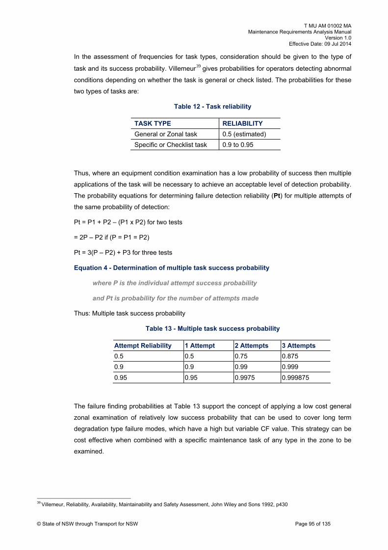
T MU AM 01002 MA Maintenance Requirements Analysis Manual
Version 1.0 Effective Date: 09 Jul 2014
© State of NSW through Transport for NSW Page 95 of 135
In the assessment of frequencies for task types, consideration should be given to the type of
task and its success probability. Villemeur39 gives probabilities for operators detecting abnormal
conditions depending on whether the task is general or check listed. The probabilities for these
two types of tasks are:
Table 12 - Task reliability
TASK TYPE RELIABILITY
General or Zonal task 0.5 (estimated)
Specific or Checklist task 0.9 to 0.95
Thus, where an equipment condition examination has a low probability of success then multiple
applications of the task will be necessary to achieve an acceptable level of detection probability.
The probability equations for determining failure detection reliability (Pt) for multiple attempts of
the same probability of detection:
Pt = P1 + P2 – (P1 x P2) for two tests
= 2P – P2 if (P = P1 = P2)
Pt = 3(P – P2) + P3 for three tests
Equation 4 - Determination of multiple task success probability
where P is the individual attempt success probability
and Pt is probability for the number of attempts made
Thus: Multiple task success probability
Table 13 - Multiple task success probability
Attempt Reliability 1 Attempt 2 Attempts pts 3 Attem
0.5 0.5 0.75 0.875
0.9 0.9 0.99 0.999
0.95 0.95 0.9975 0.999875
The failure finding probabilities at Table 13 support the concept of applying a low cost general
zonal examination of relatively low success probability that can be used to cover long term
degradation type failure modes, which have a high but variable CF value. This strategy can be
cost effective when combined with a specific maintenance task of any type in the zone to be
examined.
39 Villemeur, Reliability, Availability, Maintainability and Safety Assessment, John Wiley and Sons 1992, p430

T MU AM 01002 MA Maintenance Requirements Analysis Manual
Version 1.0 Effective Date: 09 Jul 2014
© State of NSW through Transport for NSW Page 96 of 135
The cost effectiveness of specific task examinations versus a general look for faults is clearly
evident from the probability set at Table 13. A specific examination regime of tasks with high
reliability requiring two attempts for a particular CF interval may replace a general examination
regime of low attempt reliability where many more attempts may be required to achieve the
same outcome.
US MIL-HDBK-2173(AS) provides an algorithm to calculate the optimum number of
examinations to be conducted across the CF interval. The details are contained at Section 6.2.
4.2.3 Zonal examinations
Zonal examinations are required by the RCM based analysis logic. Zonal examinations are not
directed at any particular failure mechanism but recognise that general deterioration, accidental
damage and vandalism can occur at any time. Such failures are not related to the natural failure
mechanism of the item but occur randomly at lengthy intervals.
The zonal examination directs attention to specific zones or areas of the system, and includes
checks of areas not normally examined such as inside cabinets, conducting checks of
equipment for security, obvious signs of accidental damage or leaks and general wear and tear.
The following procedures can be used to develop a zonal inspection program:
a) divide the application into zones
b) prepare a task listing work sheet for each zone including the location, a description,
access notes, etc
c) during actual analyses of systems, equipment and structures, list any general visual task
which could be conducted as a zonal external/internal surveillance on the task listing
work sheet for each zone involved
d) include the interval from the original analyses on the zone work sheet
e) as the analysis covering the items in a zone is completed, the zone should be reviewed to
consolidate examination requirements and assign task frequencies
The frequencies of examinations in each zone are established from experience and generally a
function of:
the visibility of operating equipment in the zone
the criticality of contained operating equipment in terms of consequences of failure
load rating in terms of stresses to which the equipment and associated structures are
subjected
general exposure to accidental or vandal damage

T MU AM 01002 MA Maintenance Requirements Analysis Manual
Version 1.0 Effective Date: 09 Jul 2014
© State of NSW through Transport for NSW Page 97 of 135
It should be noted that track walking by infrastructure, transmission/distribution line patrol by
maintenance staff, signal relay box examination by signalling staff, driver walk around and
substation outdoor area inspections are, to a large extent, zonal examinations.
4.2.4 Hard time rework or discard tasks
Hard time rework (overhaul) tasks must be technically feasible in terms of removing deteriorated
equipment from service prior to failure, thus failures must show a wear out tendency and be
concentrated about an average age. If failures are concentrated, scheduled restoration prior to
this age can reduce the incidence of functional failures. This may be cost-effective for failures
with major economic consequences, or if the cost of doing the scheduled restoration task is
significantly lower than the cost of repairing the functional failure.
The frequency of hard time reworks are generally estimated at acquisition on the basis of
equivalent equipment and confirmed by an aggressive age exploration program drawing on the
initial items in a batch procurement. It should be noted that this strategy may be difficult to follow
where individual items of infrastructure equipment are procured in small numbers with limited
manufacturer information or support.
Where significant numbers of equipment are available then Waybill analysis techniques can
determine the failure characteristics of the equipment and whether hard time rework is
applicable and if so what is the most cost effective overhaul period. Further details on
establishing hard time rework frequencies are listed at Unit 9.
It should be noted the disadvantages of scheduled restoration are that:
items must removed from the facility and hence require additional cost of routable pool
spares
many items do not achieve their optimum life as they are removed early
the greater level of invasive maintenance means more opportunity for human error and
quality problems
However, scheduled restoration is generally more cost effective than scheduled discard
because it involves recycling items instead of throwing them away. Additionally, the discard task
is usually mandated by fatigue and safety reasons and hence the time period is often conducted
at about one third of the value at which an increase in failure rate occurs to guarantee no
failures.
Hard time discard is usually the least cost-effective of the three preventive tasks, but where it is
technically feasible it does have certain desirable features. Safe-life limit can reduce the
frequency of functional failures which have major economic consequences.
Safe-life limits are rarely used in the rail industry and if required would flow from a test program
conducted by the manufacturer. The task frequency would of necessity be a manufacturer’s
requirement verified during acquisition and confirmed during operation.

T MU AM 01002 MA Maintenance Requirements Analysis Manual
Version 1.0 Effective Date: 09 Jul 2014
4.2.5 Combinations of tasks
For some failure modes which have safety or environmental consequences, a single task
cannot be found which reduces the risk of the failure to an acceptable level. In these cases, it
may be possible to find a combination of tasks which reduces the risk of the failure to an
acceptable level. Each task should be carried out at the frequency determined for that task.
Note that situations in which this is necessary are very rare, and the process should not be used
as a 'just in case' exercise.
4.2.6 Failure finding tasks
Failure finding tasks are associated with hidden functional failures and hence deal with the risk
associated with double failures. The theory associated with this analysis is drawn from US MIL-
HDBK-338B40.
Suffice to say that the problem of double failures is one of conditional probability i.e. given the
hidden failure (failure of the stand-by unit, Item A), what is the failure probability of item B which
will then result in total function failure. The probability of a double failure is therefore a function
of probability of failure of items A and B and the percentage downtime or unavailability of item
B. Unavailability of hidden failures is related to the time between failure finding tasks which is
set by either the reliability achievable by the hidden failure item, assuming an insignificantly
short fix time, or by the availability of the item flowing from lengthy down times due to the repair
process.
This relationship is shown in Figure 42.
40 US MIL-HDBK-338B
© State of NSW through Transport for NSW Page 98 of 135

T MU AM 01002 MA Maintenance Requirements Analysis Manual
Version 1.0 Effective Date: 09 Jul 2014
© State of NSW through Transport for NSW Page 99 of 135
Item A
Item B
FailureOccurs
Functional
UpTime
DownTime
PrimaryDouble failure area
UpTime
Legend
DownTime
Failure
Repair
A functional failure occurs when an item Bfailure occurs during the down time of item A
Downtime is the period between failure and repair and includes failure finding and repair time
Standby
Figure 42 - Probability of double failure
The probability of having a double failure is calculated by the following equation:
Equation 5 - Calculation of a double failure
Probability of Probabilityof Item Bfailing
Item A being failed
Probabilityof Item Bbeing failed
Double failure/Yearand
Failure rateof i tem Aper year
PRIMARY SYSTEM
PROTECTIVE SYSTEM
COMBINED SYSTEM
= A x B

T MU AM 01002 MA Maintenance Requirements Analysis Manual
Version 1.0 Effective Date: 09 Jul 2014
© State of NSW through Transport for NSW Page 100 of 135
Thus if in a 12 month period item B's downtime is one month then the probability of item B being
failed at any particular time during the year is 1/12 or an unavailability of 0.083. If the probability
of item A failing in a given year is 1/10 (unreliability of 0.1) then the probability of full functional
failure, that is A and B failed simultaneously, is 1/12 multiplied by 1/10 which equals 1/120
(0.0083).
The failure finding frequency can be calculated on the basis of economic return on the
investment associated with doing the failure finding examination i.e..
The annual cost
of doing the failure
finding tasksOR
The annual loss
exposure of not
doing the tasks
Equation 6 - Calculation of failure finding frequency
In this regard loss exposure is considered to cover loss to the community at large and could
factor in the death, injury and environmental damage costs as appropriate. Often the data to
support this analysis may not be available and the assessment of failure finding frequencies is
conducted by establishing an acceptable event probability and determining the failure finding
task frequency required to achieve this probability.
4.2.7 Suggested readings and references
The suggested additional readings for this section are listed below.
United States Military Standard MIL-STD-1629A / IEC 60812
Nowlan & Heap, Reliability-Centred Maintenance
United States Military Standard MIL-HDBK-2173(AS)
Moubray, RCMII
Smith, Reliability-Centred Maintenance
MSG 3 Report

T MU AM 01002 MA Maintenance Requirements Analysis Manual
Version 1.0 Effective Date: 09 Jul 2014
© State of NSW through Transport for NSW Page 101 of 135
4.3 Task packaging
4.3.1 Introduction
The maintenance analysis process creates, as its primary output, a list of tasks and associated
frequencies. These tasks, depending on the level of knowledge available to the analysts, will be
spread across a spectrum of time and event based frequencies.
Packaging refers to the activity of bringing together into packages, the individual preventive
maintenance tasks identified during the maintenance requirements analysis activity. The
objective of packaging is to provide manageable groups of activities for the maintenance
planning and control process to resource.
The process provides a mechanism for placing under a single identifying code all maintenance
to be done to an asset or set of assets at a particular geographic position at a particular point in
time. These collection of tasks are termed servicing schedules in that they are a schedule of
servicing tasks to be completed together.
4.3.2 Options
There are a number of packaging options available to the analyst. A set of guidelines should be
drawn up at the beginning of the analysis activity to guide the analysts in the production of the
packages. The guide should identify the constraints and the objectives of the packaging
process. As an example the guidelines produced for the packaging of rail vehicle (and
infrastructure equipment) servicing schedules are detailed at the end of this Section.
Packaging options available to the analyst are:
Hierarchical Set where the packages get progressively larger as the shorter frequency
activities, as multiples of the longer frequency activities, are added together. The duration to
complete the aggregated group of tasks will steadily increase unless more resources are
allocated. This is shown diagrammatically in Figure 43.
Figure 43 - Hierarchical servicing set
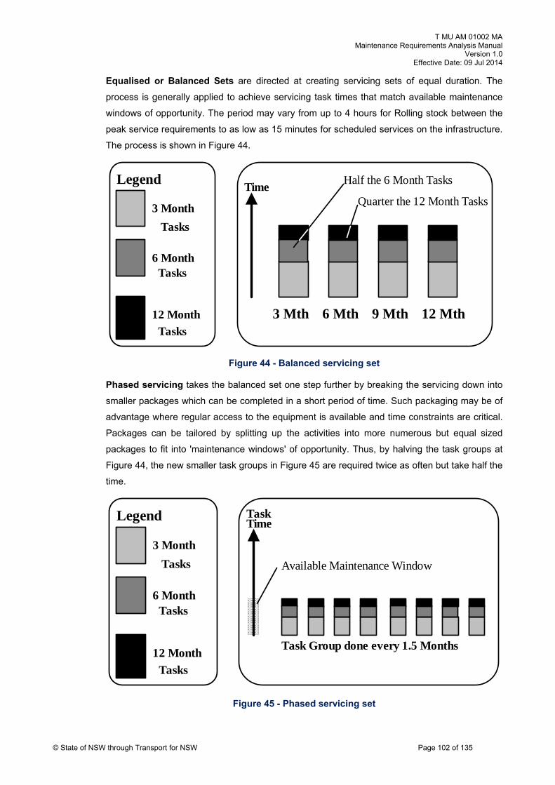
T MU AM 01002 MA Maintenance Requirements Analysis Manual
Version 1.0 Effective Date: 09 Jul 2014
© State of NSW through Transport for NSW Page 102 of 135
Equalised or Balanced Sets are directed at creating servicing sets of equal duration. The
process is generally applied to achieve servicing task times that match available maintenance
windows of opportunity. The period may vary from up to 4 hours for Rolling stock between the
peak service requirements to as low as 15 minutes for scheduled services on the infrastructure.
The process is shown in Figure 44.
3 Month
Legend
6 Month
12 Month 3 Mth 6 Mth 9 Mth 12 Mth
TimeHalf the 6 Month Tasks
Quarter the 12 Month Tasks
Tasks
Tasks
Tasks
Figure 44 - Balanced servicing set
Phased servicing takes the balanced set one step further by breaking the servicing down into
smaller packages which can be completed in a short period of time. Such packaging may be of
advantage where regular access to the equipment is available and time constraints are critical.
Packages can be tailored by splitting up the activities into more numerous but equal sized
packages to fit into 'maintenance windows' of opportunity. Thus, by halving the task groups at
Figure 44, the new smaller task groups in Figure 45 are required twice as often but take half the
time.
Figure 45 - Phased servicing set
3 Month
6 Month
12 Month
LegendTime
Tasks
Tasks
Tasks
Task
Task Group done every 1.5 Months
Available Maintenance Window

T MU AM 01002 MA Maintenance Requirements Analysis Manual
Version 1.0 Effective Date: 09 Jul 2014
© State of NSW through Transport for NSW Page 103 of 135
Special servicing are occasionally required where activities just don't fit into the packaged set
because the servicing is related to random events such as a flood or storm, or some non-time
based measure such as a number of fault openings for a bulk oil circuit breaker which cannot be
accommodated within the prime set.
4.3.3 Packaging process
Having established the packaging guidelines the following steps are taken to establish the
servicing set:
Time base the tasks. All task frequencies are brought to a common baseline, usually against
time as shown in Figure 46. Those tasks which are event based may be either left at the event
count and included as a special servicing or can be converted to a timeline by determining the
event rate and statistical distribution. Care should be taken to adequately identify those tasks
which are converted from an event to time base to ensure that when operational conditions are
changed the task frequencies are updated. Tasks should be given some form of individual
identification at this stage even if only temporary.
Timeline tasks. The average time for each task is essential to the remaining steps in the
process. As the tasks are usually stable in content with few variables, a reasonably accurate
task time should be identifiable. Care should be taken with underestimating the task time and a
test and evaluation program for any significant departures from normal practice will be
necessary.
Physically represent tasks. The tasks can then be physically represented by a piece of
cardboard cut to a scale to represent task time. This will enable various combinations of task
programming (number and certification of staff, access arrangements and relationships between
tasks) to be relatively easily tested using the constraints provided in the packaging guidelines.
Group tasks into schedules. The related sets of tasks can then be assembled into a servicing
schedule set which is applied to a particular group of assets at a particular period.

T MU AM 01002 MA Maintenance Requirements Analysis Manual
Version 1.0 Effective Date: 09 Jul 2014
© State of NSW through Transport for NSW Page 104 of 135
Figure 46 - Task aggregation - timing
4.3.4 Latitudes
Each task or schedule identified in the maintenance plan will require the allocation of a latitude
of particular value to allow for effective maintenance planning and control. The latitude sets the
maximum and minimum time span for the maintenance activity.
Latitudes are not arrangements which enable the reduction of maintenance effort by setting the
activity at the maximum frequency but a pragmatic mechanism for balancing risk against
management capability.
The determination of economic latitudes may be established with the assistance of a task cost
curve graph created in a maintenance requirement analysis system. The validity of the latitude
will be influenced by the accuracy of the CF interval determination and the business costs.
The approaches to be followed are shown at Figure 47.

T MU AM 01002 MA Maintenance Requirements Analysis Manual
Version 1.0 Effective Date: 09 Jul 2014
© State of NSW through Transport for NSW Page 105 of 135
Figure 47 - Usage of latitudes
R4New
R1 R2 R3 R4
Note: The R4 resets the counter if the servicing set is heirarchial
R4New
R1 R2 R3 R4
Note: The R4 does not reset the counter in a balanced sevicing set
BALANCED SERVICING SET
HEIRARCHIAL SERVICING SET
4.3.5 Task packaging guidelines
Prior to the packaging activity commencing, a clear and concise set of guidelines must be
provided to the analysis team. The guidelines will depend on the structure of the system being
analysed and it could be expected that distributed linear systems such as a transmission line
would have entirely different requirements than mobile items such as rolling stock, assets such
as a hole borer/crane or fixed assets such as a circuit breaker. For further details refer to
Appendix A.
As a general rule packaging guidelines will take account of the following:
available or desired maintenance windows
staff available at any particular time
staff skill mix
facility constraints regarding capacity and access
level of local decision making autonomy
4.3.6 Standard terminology
The format for servicing schedules will vary between disciplines, however the words used to
define trades staff actions must be standardised to ensure consistency of approach and to
assist the transfer of information across application boundaries. Consistency of task description
enables the provision of one training course for trades staff across the organisation and a
common interpretation of instructions and task directives by all support staff.
Each task statement should have the standard structure shown at Figure 48.

T MU AM 01002 MA Maintenance Requirements Analysis Manual
Version 1.0 Effective Date: 09 Jul 2014
© State of NSW through Transport for NSW Page 106 of 135
VERB NOUN CONDITIONAL STATEMENT
Examine attachment blocks securityfor
Figure 48 - Standard task statement structure
The verbs are the key words which define the task action and have a standardised description.
The remainder of the statement will depend on the particular item and failure mode and hence
use conventional English meanings. These key verbs are listed in Table 14:
Table 14 - Task verbs - standard terminology
Verb Detailed requirement
Examine Carry out a visua without dismantling (unless directed to do so by the ma
l survey of the condition of an itemintenance instruction).
Lubricate Apply a specified lubrarea of equipment (o
icant (e.g. oil type XYZ, grease type ABC) to a specified ften specified in a separate lubrication chart).
Check Make a comparison of a measurement of some quantity (e.g. time, pressure, temperature, resistance, dimension) to a known value (accept/reject criteria) for that measurement and if required rectify and/or replenish if necessary.
Check Operation or Operate
Ensure that an item of equipment or system functions correctly as far as possible without the use of test equipment or reference to a measurement.
Clean Remove contaminating materials (e.g. dust, dirt, moisture, excessive lubricant) from an item of equipment.
Adjust To alter as necessary to make an item compatible with system requirements.
Test functions correctly. Determine by using appropriate test equipment that a component of equipment
Replenish Refill a container to a predeterminassociated access and closu
ed level, pressure or quantity and undertake re tasks.
Fit Correctly attach an item to another.
Refit Fit an item that has been previously been removed.
Calibrate resistance, dimension or other qulaboratory function).
Make a comparison of a measurement of time, pressure, temperature, antity to a known standard (usually a NATA
Disconnect Uncouple or detach cables, pipelines or controls.
Reconnect Reverse of disconnect.
Safety seal Securing of equipment which requires the breaking of a seal to manually operate (usually associated with emergency equipment).
Remove Correctly detach one item from another.
Secure To make firm or fast.

T MU AM 01002 MA Maintenance Requirements Analysis Manual
Version 1.0 Effective Date: 09 Jul 2014
© State of NSW through Transport for NSW Page 107 of 135
4.3.7 Suggested readings and references
The suggested additional readings for this section are listed below.
Nowlan & Heap, Reliability-Centred Maintenance
United States Military Standard MIL-HDBK-2173(AS)
Moubray, RCMII
Smith, Reliability-Centred Maintenance
MSG 3 Report
5. Audit and evaluation
5.1 Auditing
5.1.1 Introduction
Although the RCM analysis is conducted by the best technical and engineering staff available
and facilitated by experienced analysts, bias may be introduced during the analysis.
The auditing of the analysis process and the resulting decisions is essential to counter either the
familiarity possessed by internal staff or the lack of visibility of the process in an external
provider.
An independent review of the analysis decisions ensures that the logic has been properly
applied and reduces the probability of errors of judgement.
Additionally, as the analysis process involves the establishment of significant policy decisions,
senior management are not absolved from accountability for the outcomes. Accordingly the
audit process provides a mechanism through which management can assure itself that defined
procedures have been followed and sustainable outcomes achieved. The audit may be done by
senior management staff themselves or by delegation, provided the auditor is properly qualified
and experienced to undertake the audit function.
Auditing is best conducted independently of, and if possible externally to, the group performing
the analysis. The audit process should include the areas listed below:
significant item selection
determination of item functions, failure modes, cause and effects
classification of failure consequences
evaluation of applicability and effectiveness criteria
task packaging guidelines
T MU AM 01002 MA Maintenance Requirements Analysis Manual
Version 1.0 Effective Date: 09 Jul 2014
© State of NSW through Transport for NSW Page 108 of 135
5.1.2 Timing of the audit
Audits should be carried out progressively
Audits should be carried out progressively as each system review is completed for the following
reasons:
analysis group members may change from system to system and the audit should be
conducted while team members are still available
early audits will make for easier recall of the basis for decisions if documentation is
unclear
the audit process will provide valuable feedback to analysis team members and improve
performance on the remaining task
early approval of analysis results may allow their issue as policy and hence gain the
benefits of the decision
5.1.3 Auditor selection
A chief pre-requisite for auditors is a clear understanding of the RCM principles.
Knowledge only of the equipment or technologies being analysed will not be adequate and will
threaten the achievement of an objective review. Auditors must primarily be completely familiar
with the RCM process and be able to detect errors in logic and documentation.
Additionally, they must have a working knowledge of the technical aspects of the system to be
able to properly audit the key functional description statement. When analysis is conducted as a
part of asset acquisition program, the requirement for audit by the procuring organisation, where
both procedural and technical knowledge exist, should be included in the procurement contract.
5.1.4 Significant item selection
The sharing of common definitions of significant items and operational consequences by
analysts and auditors is essential. In this regard:
identification of significant items is based on their failure consequences not on the item
cost or its complexity. Failure consequences refer to the direct impact that the loss of a
particular function has on the safety and service capability of the equipment not on the
number of failure modes or their effect on the item itself.
the circumstances that establish service consequences and their costs must be clearly
defined. This information is essential to the determination of economic consequences and
should be supported by a simple readily understood economic analysis.

T MU AM 01002 MA Maintenance Requirements Analysis Manual
Version 1.0 Effective Date: 09 Jul 2014
© State of NSW through Transport for NSW Page 109 of 135
5.1.5 Item function, failure and effects
The recorded data should provide for clear traceability of task outcome via the provision of
adequate and clearly presented information at each step of the analysis process. Auditors
should be satisfied that each task is completely traceable.
Traceability should be available in both directions. Beginning at a function, traceability through
to the task assigned to protect that function or beginning with a task to backtrack through to the
reasoning that led to its selection.
Auditors should pay particular attention to the detection of the following:
Improper definitions of the function of an item
is there a clear functional diagram of the system or equipment?
is the selected level correct?
are all the hidden functions identified?
have all secondary functions been listed?
Confusion between functional failures and engineering failure modes
does the failure mode describe the lost function rather than the manner in which the
failure occurs?
are failure modes that have never actually occurred been listed?
are the failure modes reasonable given experience with similar equipment?
have any important failure modes been overlooked?
does the description of the failure relate to the cause of the failure rather than it’s
immediate results?
Description of failure effects to include all information necessary to support the consequence
evaluation
is a description of the physical evidence used by the operator to identify the failure
included?
are the effects of secondary damage clearly stated?
does the description identify the ultimate effects of the failure given no preventive
maintenance?
are the effects of 'protected' functional failures associated with hidden or 'protective'
functional failures stated?

T MU AM 01002 MA Maintenance Requirements Analysis Manual
Version 1.0 Effective Date: 09 Jul 2014
© State of NSW through Transport for NSW Page 110 of 135
5.1.6 Classification of failure consequences
The first four questions in the decision logic (see Figure 35) identify the consequences of each
type of failure and direct the analyst to the particular branch of the analysis process to be
applied. These answers to these questions are particularly significant and hence warrant special
attention during auditing.
Again the basis of each answer should be clearly traceable in the documentation and auditors
should pay particular attention to:
The identification of hidden function failures:
has the evident failure question been asked of the functions not the item?
has operator instrumentation been overlooked as an indication system?
have redundancies without indication of failure been adequately considered?
have the hidden function of emergency items been overlooked?
have built in test functions been properly assessed in regard to failure visibility to the
operator?
The identification of safety and safety hidden failures:
has the failure been identified as critical on the basis of double failure consequences
rather than the consequences of a single failure?
has it been identified as critical because it requires immediate corrective action? i.e. it is
service critical.
has the analyst taken into account redundancy or fail safe design features that prevent
the functional failure from being critical?
5.1.7 Evaluation of applicability and effectiveness criteria
When auditing the selected tasks for applicability criteria, the auditors should assure themselves
that the analyst understands the resolving power of the types of tasks available and the
conditions under which each type of task is applicable. Of importance is the fact that if the task
is directed at the mere examination of an item of equipment for condition rather than a specific
failure mode, then it is not an on-condition task.
An on condition task must be directed at a failure mode that has a definable potential failure
stage with an adequate and fairly predictable interval for examination.

T MU AM 01002 MA Maintenance Requirements Analysis Manual
Version 1.0 Effective Date: 09 Jul 2014
© State of NSW through Transport for NSW Page 111 of 135
The audit checklist for the application of these criteria to the possible maintenance task types is:
are on condition monitoring tasks feasible and practical?
have the age characteristics been established for hard time tasks?
will rework restore original reliability (particularly if the item under study has no empirical
evidence to justify the assumption)?
is the task interval applied to hard time tasks cost effective?
have manufacturer’s recommendations been followed and if not is justification clearly
presented?
are the failure finding tasks linked to hidden functional failures only?
have the appropriate items been assigned to an age exploration program?
Effectiveness criteria depend completely on the objective of the particular task and the
consequences it is intended to prevent. The same task type will vary in its effectiveness
depending on the application. The audit checklist for effectiveness criteria are as follows:
do the tasks and periods selected have an acceptable probability of preventing all critical
failures?
what is the basis for accepting residual risk levels?
do hard time tasks (if specified) adequately prevent critical failures or just control them?
what mechanisms are available for the application of default strategies?
is the mechanism for determining cost effectiveness clearly visible?
is the cost of service interruptions realistic and based on approved criteria?
are there adequate mechanisms to quantify risk in relation to safety and service related
events?
do failure finding tasks duplicate the operator activities?
5.1.8 The completed program
After analysis of individual sections is complete and their results audited separately, the
program as a whole following task aggregation may need auditing. This activity ensures that:
aggregation activities have considered all options
any variations to task frequencies go through the audit process

T MU AM 01002 MA Maintenance Requirements Analysis Manual
Version 1.0 Effective Date: 09 Jul 2014
© State of NSW through Transport for NSW Page 112 of 135
5.1.9 Suggested readings and references
The suggested additional readings for this section are listed below.
Nowlan & Heap, Reliability-Centred Maintenance
United States Military Standard MIL-HDBK-2173(AS)
Moubray, RCMII
Smith, Reliability-Centred Maintenance
MSG 3 Report
5.2 Test and evaluation
5.2.1 Introduction
The introduction of new preventive maintenance schedules brings with it an element of risk
which must be managed by the responsible and accountable authority for the subject
equipment.
A significant element in the risk management of new maintenance schedules is the conduct of a
test and evaluation program which confirms the theoretical and experiential decisions made
during the analysis and protects against unanticipated risks.
The risks associated with a new or modified schedule set are considered to be:
safety risks associated with task sequencing and task conduct
service risks associated with task description and duration, inventory and support
equipment needs
economic risk associated with task description and duration
human resource risks associated with any change
The requirement for a formal test and evaluation of either initial or modified preventive
maintenance programs will generally be subject to engineering judgement within a set of
defined guidelines. These guidelines are contained in the following paragraphs which are
divided into two different origins for analysis activity.
5.2.2 Initial schedules - new equipment
The purchase of new equipment, not currently in-service, will inevitably require the specification
of new maintenance policies and their associated servicing schedules. These policies and their
supporting schedules should be delivered before the arrival of such equipment in accordance
with the requirements imposed by functional/performance specifications regarding system
support.

T MU AM 01002 MA Maintenance Requirements Analysis Manual
Version 1.0 Effective Date: 09 Jul 2014
© State of NSW through Transport for NSW Page 113 of 135
The system/equipment specification, if formatted in US MIL-STD-49041 or equivalent format, will
require the maintenance plan, servicing schedule and maintenance task data including
associated analysis as deliverables which clearly show, in accordance with the procedures
outlined in this manual, how the maintenance policies and associated task descriptions were
derived.
The test and evaluation program for the schedules will also be included in the deliverables list
and will usually be a milestone in the procurement program as a demonstration that
maintainability targets such as MTTR and MDT have been achieved.
The evaluation should also include checks on the suitability of the assigned facilities, the
available support equipment and their expected interaction with the proposed maintenance
schedule.
5.2.3 Initial schedules - in-service equipment
Despite the best intentions of organisations to procure properly documented systems, there will
be a need from time to time to undertake the maintenance analysis of new equipment which, for
a variety of reasons, may have arrived without a well documented set of maintenance
requirements. Individual pieces of equipment procured on a one-off replacement basis without
coverage of a period contract requiring standardisation may not have an RCM based
maintenance program.
New schedules developed in accordance with this program should be tested in the same
manner as for new equipment during its test and evaluation phase. A typical brief for the test
and evaluation of a significant maintenance schedule change is shown at Section 5.2.5.
5.2.4 Suggested readings and references
The suggested additional readings for this section are listed below.
Nowlan & Heap, Reliability-Centred Maintenance
United States Military Standard MIL-HDBK-2173(AS)
Moubray, RCMII
Smith, Reliability-Centred Maintenance
MSG 3 Report
41 US MIL-STD-490, Specification Practice

T MU AM 01002 MA Maintenance Requirements Analysis Manual
Version 1.0 Effective Date: 09 Jul 2014
© State of NSW through Transport for NSW Page 114 of 135
5.2.5 Test and evaluation program brief
a) Introduction
A comprehensive reliability-centred maintenance (RCM) analysis program is being undertaken
to develop technical maintenance plans and their associated servicing schedules. The program
will produce a set of maintenance schedules which must be verified before approval can be
given to their application in the field.
b) Objective
The objective of this brief is to define the services required to implement and document a test
and verification program for the servicing schedules developed by a new decision process
(RCM analysis).
c) Scope of work
The program will include the following activities:
identify the content of a test and evaluation program that will:
provide the accountable engineering manager with clear and concise evidence
necessary for sign off on the safety aspects of the schedule
confirm the ability of the schedule to achieve its required maintenance window
criteria
confirm the task sequencing and task relationships specified in the schedules
confirm or enhance the logistic support (test equipment, tools and spares)
requirements established during the analysis
develop an implementation project plan for the identified test and evaluation program
develop a risk management program that, as a minimum covers safety, industrial
relations and technical risk exposures
undertake, or as necessary arrange, the familiarisation and training of staff requisite for
the success of the program
collect technical and administrative data necessary to complete an effectiveness
evaluation of the process
on completion of the test and evaluation program:
produce a report on the effectiveness of the total process (RCM analysis and
subsequent schedule development) in agreed quantitative measures
identify the necessary changes to the original analysis documentation following
completion of the evaluation
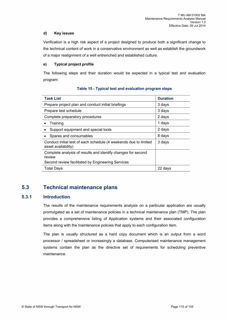
T MU AM 01002 MA Maintenance Requirements Analysis Manual
Version 1.0 Effective Date: 09 Jul 2014
d) Key issues
Verification is a high risk aspect of a project designed to produce both a significant change to
the technical content of work in a conservative environment as well as establish the groundwork
of a major realignment of a well entrenched and established culture.
e) Typical project profile
The following steps and their duration would be expected in a typical test and evaluation
program:
Table 15 - Typical test and evaluation program steps
© State of NSW through Transport for NSW Page 115 of 135
Task List Duration
Prepare project plan and conduct initial briefings 3 days
Prepare test schedule 3 days
Complete preparatory procedures 2 days
Training 1 days
Support equipment and special tools 2 days
Spares and consumables 8 days
Conduct initial test of each schedule (4 weekends due to limited asset availability)
3 days
Complete analysis of results and identify changes for second review
d review faciliSecon tated by Engineering Services
Total Days 22 days
5.3 Technical maintenance plans
5.3.1 Introduction
The results of the maintenance requirements analysis on a particular application are usually
promulgated as a set of maintenance policies in a technical maintenance plan (TMP). The plan
provides a comprehensive listing of Application systems and their associated configuration
items along with the maintenance policies that apply to each configuration item.
The plan is usually structured as a hard copy document which is an output from a word
processor / spreadsheet or increasingly a database. Computerised maintenance management
systems contain the plan as the directive set of requirements for scheduling preventive
maintenance.

T MU AM 01002 MA Maintenance Requirements Analysis Manual
Version 1.0 Effective Date: 09 Jul 2014
© State of NSW through Transport for NSW Page 116 of 135
5.3.2 Item listing criteria
The TMP lists items when:
they are repairable
they have a defined maintenance policy (that is the item has scheduled maintenance
activity at a defined interval)
they require some special maintenance management input and thus will need certain
information to be recorded
5.3.3 Plan information
The TMP provides maintenance policy information and includes as a minimum:
which items are maintained
what maintenance is carried out
when maintenance is carried out
who performs the maintenance
where maintenance is carried out
how maintenance is carried out (cross reference to quality document)
5.3.4 Responsibility
The content of the TMP is the responsibility of an authorised engineering manager normally
defined in a configuration management plan. Procedures for management of the data contained
in a TMP are defined in this publication and the specific Appendix for the particular application.
Specific maintenance requirements are continually under review, therefore the contents of each
TMP are regularly revised as necessary. Applicable configuration management practices must
be applied in the development and issue of technical maintenance plans to ensure currency and
auditability.
5.3.5 Suggested readings and references
The suggested additional readings for this section are listed below.
Nowlan & Heap, Reliability-Centred Maintenance
United States Military Standard MIL-HDBK-2173(AS)
Moubray, RCMII
Smith, Reliability-Centred Maintenance
MSG 3 Report

T MU AM 01002 MA Maintenance Requirements Analysis Manual
Version 1.0 Effective Date: 09 Jul 2014
© State of NSW through Transport for NSW Page 117 of 135
6. MRA techniques and policy
6.1 Age exploration
6.1.1 Introduction
Age exploration is a process associated with the application of RCM analysis techniques in
accordance with the procedures outlined by the IATA Maintenance Steering Group 2/3 and MIL-
HDBK-2173(AS) and described in detail in Nowlan and Heap.
The process is primarily established to iteratively refine initial maintenance tasks and associated
frequencies resulting from RCM analysis conducted during the design stage of new equipment.
Initial estimates of failure modes, equipment failure characteristics, MTBF and MTTF which
determine tasks and their associated frequencies must be verified and if necessary varied to
suit actual equipment performance.
6.1.2 Process
Age exploration has three main elements:
Failure data collected during normal operation of the equipment is analysed to determine
the accuracy of original estimates of MTBF or, in the absence of a mathematical
approach, the use of maintainer experience.
During routine repair of failed items, additional tasks may be inserted in the repair
process to examine the condition of components prone to wear or fatigue. The results of
this analysis are then used to either establish an overhaul period if not yet set or to verify
an already defined frequency.
Investigative maintenance activities are conducted to ascertain the failure degradation
rates of significant equipment or components. Significance is allocated on the basis of
complexity, cost or criticality. The process may vary from the relatively low cost
determination of consumable (lubricants, motor brushes) rates of loss or deterioration, to
the more costly full strip, examination and report on larger equipment such as electric
motors, pumps, air conditioners or compressors.
6.1.3 Research opportunities
The age exploration process will often include the need for research briefs to be established to
improve the entire maintenance process. Such briefs may involve improving the knowledge of
failure mechanisms and identifying opportunities for advanced technology to enable the
implementation of condition monitoring tasks.
The application of a wide range of condition monitoring techniques are available to the
professional maintainer and often simple and unsophisticated techniques such as temperature
sensitive tapes may provide invaluable data on operational overheating.

T MU AM 01002 MA Maintenance Requirements Analysis Manual
Version 1.0 Effective Date: 09 Jul 2014
© State of NSW through Transport for NSW Page 118 of 135
6.1.4 Cost effectiveness
At all times the cost effectiveness of the age exploration process should be considered in the
light of its expected cost and its expected outcomes. An age exploration plan and its associated
procedures should be established for each application and included within the engineering
management plan for the responsible engineering authority. The program must be costed to
ensure return on investment and have clearly allocated responsibilities and accountabilities to
ensure useful outcomes are achieved.
6.1.5 Responsibilities
The age exploration (Agex) program is an integral element of the quality management approach
as it applies to the continual improvement of the content of the technical maintenance plans.
The quality management principles behind this program require the allocation of management
priorities to candidate systems and equipment on the basis of cost of ownership. That is,
candidates for age exploration are selected using the Pareto principle on the basis that the
largest savings can most probably be achieved from optimising the largest expenditures.
Ownership of the age exploration process resides with the engineering function and should
have a well defined owner who has accountability and responsibility for the proactive process of
continual improvement.
6.1.6 Summary
An Agex program can be a valuable tool in refining initial maintenance program estimates into
more cost effective tasks and their frequencies. Care should be taken that the program is well
defined (formal and visible) in terms of process, prioritisation and ownership. Some form of plan
will usually be necessary to ensure that objectives and their supporting activities are properly
selected and applied in a structured and cost effective manner.
6.1.7 Suggested readings and references
The suggested additional readings for this section are listed below.
Nowlan & Heap, Reliability-Centred Maintenance
United States Military Standard MIL-HDBK-2173(AS)
Moubray, RCMII
Smith, Reliability-Centred Maintenance
MSG 3 Report

T MU AM 01002 MA Maintenance Requirements Analysis Manual
Version 1.0 Effective Date: 09 Jul 2014
© State of NSW through Transport for NSW Page 119 of 135
and the formula are shown at Figure 49.
6.2 Task frequency algorithms
6.2.1 Introduction
The determination of task frequencies can be enhanced in terms of both accuracy and speed of
decision making by the application of quantitative decision analysis techniques. The use of
algorithms enables the rapid assessment of possible task options and the sensitivity of the
outcome to estimation errors in the various elements.
The three task types most amenable to the use of algorithms are:
condition monitoring
hard time (overhaul or restoration)
failure finding
Three decision algorithms which support the RCM decision are listed in the following
paragraphs.
6.2.2 Condition monitoring algorithm
This algorithm is derived from US MIL-HDBK-2173(AS) and described at pages 58-59. A
diagram of the algorithm
100%
TO FAILURE
CONDITIONALFAILURE
RESISTANCE VISIBLE EVIDENCE of FAILURE
FUNCTIONALFAILURET
OPERATING AGE T T0%
CF Interval
Repair $
Where T = Time between Conditionaland actual Functional Failure
T = Time between successive examinations
Repair $
Service Loss $
External Impact $Maintenance Cost $
MTBF
Failure DetectionProbability
Figure 49 - Condition Monitoring Algorithm
The algorithm for determining the optimum number of examinations 'n' across the CF interval is:

T MU AM 01002 MA Maintenance Requirements Analysis Manual
Version 1.0 Effective Date: 09 Jul 2014
© State of NSW through Transport for NSW Page 120 of 135
1lnn
1ln
lnCpfCnpm
CeT
MTBF
Equation 7 - algorithm for determining the optimum number of examinations
Where:
n = Optimum number of condition examinations in the time
interval between conditional (potential) failure and functional
failure
T = Time interval between conditional (Potential) failure and
functional failure
ΔT = Time interval between examinations
MTBF = Mean Time Between Failures or the average life
expectancy of the equipment if allowed to run to failure
Ce = Cost of each examination
Cpf = Cost of correcting each conditional failure
Cnpm = Cost of not doing preventive maintenance (i.e. cost of
unplanned failure)
θ = Probability of detecting the failure in a single examination
The algorithm requires the following assumptions:
MTBF >> T
possible to detect reduced failure resistance for a given failure mode
possible to define a potential failure condition (parameter and value) that can be detected
by an explicit task
must be a reasonably consistent age interval between the time of conditional failure and
functional failure
the probability of detecting the failure in one examination is constant

T MU AM 01002 MA Maintenance Requirements Analysis Manual
Version 1.0 Effective Date: 09 Jul 2014
© State of NSW through Transport for NSW Page 121 of 135
6.2.3 Double failure algorithm
This algorithm considers the implications of a failed protective system and a failed primary
system and calculates the optimum maintenance period for a failure finding task based on
minimum total cost of maintenance plus risk exposure.
The model shown at Figure 50 describes the basic 'fault - event tree' or 'cause - consequence'
diagram that may be used to determine the optimum failure finding task time T. In the Figure 50
maintenance cost is a function of condition monitoring task cost and task frequency while cost
of failures is a function of:
primary item failure rate (fixed)
protective item/system failure rate (variable depending on failure finding task time T)
probability and cost of possible outcomes following double failure to establish a cost
value per event.
Figure 50 - Failure finding task frequency
FAILURE FINDING TASK
Is a failure
finding task
applicable and
effective
Primary ItemAdverse
EventPossible
Protective ItemLOC
Outcomes
$
Optimum Task Time
MaintenanceCost
Cost ofFailures
Total Cost of Task Freq
Model
Cost Profile

T MU AM 01002 MA Maintenance Requirements Analysis Manual
Version 1.0 Effective Date: 09 Jul 2014
© State of NSW through Transport for NSW Page 122 of 135
A formula is not available from standards and texts. The time interval T (optimum task
frequency) for the task period can be calculated by determining a value for T that will provide
equal values for maintenance cost and cost of failures. This assumes that the failure rate of the
protective maintenance system is negative exponentially distributed (random).
As depicted in the $/Time curves in Figure 50 the combined outcome ($ maintenance + $ failure
cost) for a given task time, is very flat around the optimum task time. The process is thus quite
robust and not particularly sensitive to minor errors when estimating cost.
6.2.4 Hard time algorithm
Decision algorithms are available commercially for determining hard time tasks such as
overhaul. Weibull Probability paper can be used to establish the optimum interval for an age
based preventive replacement policy (hard time restoration). The procedure is described in
Jardine, Maintenance Replacement and Reliability and can be readily conducted using
commercial off-the-shelf software.
For hard time tasks it should be remembered that from the United Airlines actuarial study, only
6% of items supported application of a hard time maintenance activity. Additionally, the
algorithms require quality mean time between failure data which is usually lacking in most
organisations.
However, certain items will exhibit a dominant failure mechanism and may be usefully managed
with a hard time restoration (overhaul) or discard process.

T MU AM 01002 MA Maintenance Requirements Analysis Manual
Version 1.0 Effective Date: 09 Jul 2014
© State of NSW through Transport for NSW Page 123 of 135
SCHEDULED (HARD TIME) RESTORATIONAND DISCARD TASK
Is a hard timerestoration taskapplicable andeffective
Is a hard timediscard taskapplicable andeffective
Item Wear Out
Restoration Period
ulations of items onlyFor pop
Optimum Task Time
MaintenanceCost Cost of
Failures
Total Cost of Task Freq
$
Model
Cost Profile
Failure
Time
Rate
Figure 51 - Hard time task frequency
In regard to hard time total cost of task curve, note that the cost of failures curve is not straight
(that is; random failure pattern), but represents a wear out failure pattern with an increasing
failure rate with time. Hence the optimum time is earlier than the maintenance/failure cost cross
over point and the curve has greater sensitivity to variations in task time T.

T MU AM 01002 MA Maintenance Requirements Analysis Manual
Version 1.0 Effective Date: 09 Jul 2014
© State of NSW through Transport for NSW Page 124 of 135
6.3 Level of repair analysis
6.3.1 Introduction
Level of repair analysis (LORA) is a process for determining whether equipment should be
maintained at all and, if so, whether equipment should be maintained on or off the prime
Application or its operating systems.
The LORA process requires an explicit statement of whether the rail maintenance system
supports a two or three level maintenance organisation (operational, workshop and contractor).
This should be defined in the maintenance concept for the application and documented in the
appropriate engineering management plan. However, while each maintenance decision must
stand alone in regard to cost effectiveness, care should be taken that facilities are not used just
because they are there and that the total implications of continuing with a local facility is
considered.
Information essential to effective LORA at the design stage is a detailed operational
requirement and maintenance concept. With systems already in-service this information as well
as actual cost data should be readily available. Using the checklists available simple
spreadsheets should be adequate for any necessary analysis.
6.3.2 Repair versus replace decisions
Considerable theoretical mathematical work has been done on repair versus replace decision
algorithms. United States MIL-STD-1390D Level of Repair Analysis contains a large number of
optional algorithms to be applied to repair versus replace decision making. However, the
algorithms require considerable amounts of hard data regarding reliability, maintainability and
logistics costs which are rarely available in most organisations undertaking maintenance
requirements analysis for the first time.
Considerable theoretical work has also been done by Professor A K Jardine in the application of
Weibull analysis to determine optimum repair and replace strategies for equipment which have
a primary wear out failure mechanism. A large number of possible algorithms are defined in
Jardine, Maintenance Replacement and Reliability, Pitman Publishing.
Having decided that 'repair' and not 'replace' is the most economic activity, the following
paragraphs provide some options to be considered regarding where to do the maintenance. It
should be recognised that such decisions also affect the cost of repair and that there is an
iterative loop in the repair versus replace decision process.

T MU AM 01002 MA Maintenance Requirements Analysis Manual
Version 1.0 Effective Date: 09 Jul 2014
© State of NSW through Transport for NSW Page 125 of 135
6.3.3 Repair in-situ
The need to repair in-situ is usually driven by the technical or physical inability to remove the
component and replace it with a spare. For many large items of plant or infrastructure
equipment whose structure is virtually built into the plant, removal is not an option. Examples of
such items are structural repairs and repairs to linear assets such as wiring, piping, track,
transmission or distribution lines, underground cables etc.
6.3.4 Repair at local workshop
The repair process is conducted locally at a workshop because some key cost elements such
as:
distance from alternate repair facility
no alternate technical capability
limited allowed down time (no replacement item) and high-cost of a replacement spare
part
low cost and technology repair process
limited need for specialised test equipment
cost is always the primary driver of decisions between alternatives and an economic
analysis conducted where decisions are not obvious (see Figure 52)
6.3.5 Repair at contractor facility
The use of external contractor facilities can be a contentious issue. Again economic rational
approaches to decision making are necessary to ensure that repair decisions follow a consistent
approach.
External contractors are normally used in circumstances where:
the function is contestable
high-cost specialist support equipment is not necessary
critical mass of activity necessary to maintain internal skills is not available
the item is common to many other users and supported by efficient specialist
maintenance facilities

T MU AM 01002 MA Maintenance Requirements Analysis Manual
Version 1.0 Effective Date: 09 Jul 2014
© State of NSW through Transport for NSW Page 126 of 135
6.3.6 Process map for LORA
System designinformation
Practical screeningSafetyPolicy
Determinecandidates
Technical
Economic screening
Risk
Clear
Marginal
FrequencyCost
Detailed analysisRelaibilityMaintenanceSparesTransport
Consistency checkOperational needsMaintenance concept
port Logistic sup
Enunciate policyProvide logistic support
Clear
arginalM
Pass
Fail
Figure 52 - LORA process map (Blanchard)
A more detailed description of the LORA process described in the process map at Figure 52 is
contained in Blanchard, Systems Engineering Management Pages 329-335.

T MU AM 01002 MA Maintenance Requirements Analysis Manual
Version 1.0 Effective Date: 09 Jul 2014
© State of NSW through Transport for NSW Page 127 of 135
6.4 MRA policy
6.4.1 Introduction
TfNSW has progressively applied customised RCM analysis techniques to determine the
optimum preventive maintenance requirements of the infrastructure and fleet assets of the NSW
statutory rail authorities and corporations. This activity represents a considerable investment in
the future management of their capital assets and should not be diluted by the addition of
equipment without similar justification and documentation of preventive and corrective
maintenance requirements.
Maintaining the validity of the maintenance requirements analysis data requires ensuring that
future assets are not procured without the necessary maintenance planning action. Additionally,
the procurement of new assets should not require the application of valuable engineering
resources to determine or justify their preventive maintenance programs.
Procurement action should wherever possible include the justification of any maintenance
actions provided by the system supplier.
The detailed procedures used by each discipline in determining their preventive maintenance
requirements are attached in the appropriate appendixes. The data structures of the
maintenance requirements analysis described in the appendices for each discipline should drive
the minimum requirements of supporting maintenance data from suppliers.
6.4.2 Supplier recommendations
Some observations on maintenance recommendations from individual equipment or component
suppliers would seem appropriate at this time.
Contractual requirements for suppliers to provide recommendations for the maintenance of their
equipment provide little assurance that either appropriate or optimum maintenance will be
forthcoming.
Equipment and component suppliers for commercial off-the-shelf (COTS) systems and
equipment provide for a mass general-purpose market. Rarely, do they know either the
operating environment or the functional criticality of the application of their equipment. Any
maintenance recommendations they may make relate therefore to the protection of their
warranties in an unknown environment. Their recommendations therefore, of necessity, manage
risk exposure through the specification of a lowest common denominator maintenance program.
System providers, who understand the system operating environment and criticality, have the
knowledge to integrate equipment suppliers into an effective maintenance system and should
through contractual arrangements own the risk associated with the specification of maintenance
requirements. The proper determination and documentation of those maintenance requirements
should be progressively verified through the design review process contained in AS ISO 10007-
2003: Quality management systems - Guidelines for configuration management.

T MU AM 01002 MA Maintenance Requirements Analysis Manual
Version 1.0 Effective Date: 09 Jul 2014
© State of NSW through Transport for NSW Page 128 of 135
6.4.3 New systems
Maintenance planning is an element of logistic support and provides the complete list of
preventive and corrective maintenance actions required to support a new capital asset.
The procurement of major new capital assets provides an opportunity for maintenance planning
and life cycle cost data to be provided directly from the supplier of the new assets. Suppliers
have access to design data that assist in the ready definition of maintenance requirements and
asset procurers must ensure that such data is made available for the future management of the
asset through the necessary logistic support requirements of the contract.
For major new procurements, a maintenance requirements analysis program should consist of
the following elements:
a maintenance concept for new equipment that is used in the conceptual phase of the
program when establishing the procurement specification for new capital assets
development of corrective maintenance requirements using FMECA and maintenance
task analysis techniques
development of the preventive maintenance program using RCM analysis techniques
according to the principles contained in this book and its associated reference documents
the continuing review and update of the preventive program requirements using the
techniques of age exploration to refine the estimates and assumptions used to establish
the initial program
This program should be tailored to new procurements and subject to the necessary design
reviews that will be cost effective and ensure that the necessary maintenance programs are in
place.
6.4.4 Individual equipment replacement
As stated previously, FMECA and RCM analysis data is rarely available for COTS equipment.
When individual purchase of COTS replacement or minor enhancing equipment is necessary,
good sense should prevail and the requirements for cost effectiveness of the replacement asset
followed. Government requirements for 'value' in contracting provide for proper assessment of
new inventory items in regard to life cycle cost. This includes the provision of justifiable
maintenance plans.
Purchase of new inventories provides an opportunity to both improve the reliability and
availability of the systems and ensure that these improvements are not lost through
inappropriate or at worst non-existent maintenance policies. Accordingly individual equipment
with critical performance requirements should be replaced only with items that have a verifiable
set of performance characteristics including cost of maintenance.

T MU AM 01002 MA Maintenance Requirements Analysis Manual
Version 1.0 Effective Date: 09 Jul 2014
© State of NSW through Transport for NSW Page 129 of 135
New equipment should therefore be procured with the necessary justification of maintenance
requirements specified to be provided by the manufacturer for the defined operating
environment.
6.4.5 Existing equipment modification
The modification of in-service equipment by either partial change or replacement requires
management in accordance with defined configuration management practices. Such changes
should be subject to engineering change request (ECR) action as defined in the configuration
management policy manual. The requirement for maintenance analysis is a defined 'change
impact' assessed during the development of the ECR.
Any necessary MRA action should be undertaken by the party accountable for designing and
validating the modification to ensure cost effectiveness and accountability.
6.4.6 Maintenance reviews
Reviews of maintenance requirements may be either:
pro-active, that are initiated by management as a result of performance monitoring of
data provided from sources such as a computerised maintenance management system,
or
reactive, that respond to initiating events such as high consequence failures, changes to
level of use or need, changes to maintenance task techniques and costs, or changes to
system configuration through introduction of new equipment
6.4.7 Pro-active reviews
Pro-active reviews apply top down quality management practices of monitoring and, where
possible, benchmark performance indices such as:
cost of ownership
ratios of conditional failures versus functional failures
ratios of preventive versus corrective maintenance
system availability derived from equipment reliability and maintainability data.
other maintenance-related performance data
These reviews assess the suitability of the current maintenance program by assessing the
assumptions and data used to establish the present maintenance requirements. The
assessment establishes whether system performance can be improved through maintenance
action or whether a change in equipment configuration by either modification or replacement is
necessary and cost effective.

T MU AM 01002 MA Maintenance Requirements Analysis Manual
Version 1.0 Effective Date: 09 Jul 2014
© State of NSW through Transport for NSW Page 130 of 135
Reviews of maintenance requirements should focus on the completeness and accuracy of the
assumptions as the primary driver of task criticality, task frequency and task packaging criteria.
The reviews should be conducted on a regular basis and be part of a defined continual
improvement program.
6.4.8 Reactive reviews
Reactive reviews flow from significant changes in the drivers of maintenance requirements.
These include:
business requirements such as level of service
operational requirements such as rate of effort and required utilisation
technical performance such as critical one-off system or equipment failures
maintenance performance such as rapidly increasing failure rates for particular
equipment types
Reactive reviews follow the standard MRA practices but in a more narrowly focused manner to
determine just the particular maintenance policy changes necessary to manage the defined
problem.
Failure reporting and corrective action systems (FRACAS) provide a standardised method for
applying reviews of maintenance policy as the first step in the development of solutions to a
particular maintenance problem.
7. Analysis of safety critical items
7.1 Introduction
This section supports the TfNSW Asset Management Policy with an outline of a possible
process available for addressing safety critical items. This section is not intended to be a
definitive reference on how to perform analysis of safety critical items, but to provide an
overview of possible process.
A safety critical failure is defined as “A loss of a function or secondary damage resulting from a
given failure mode which produces a direct adverse effect on safety.”42
42 MIL-HDBK-2173(AS), p5

T MU AM 01002 MA Maintenance Requirements Analysis Manual
Version 1.0 Effective Date: 09 Jul 2014
© State of NSW through Transport for NSW Page 131 of 135
7.1.1 Quantitative risk assessment
In establishing a quantitative risk model for the safety critical fault being analysed the following
steps need to be completed to establish a basic cause / consequence diagram.
a) Establish fault tree structure for safety critical fault event. This should include both
equipment and human elements/events, and the logical relationships (AND, OR etc)
between the events for progression to the next higher level event. All assumptions should
be clearly stated and documented.
b) Collect output data from RCM analysis, or other data sources, to establish the equipment
related failure probabilities in the fault tree.
c) Collect human event failure data for human related exposure / failure probabilities in the
fault tree.
d) Establish safety critical event probability.
e) Establish realistic scope of consequences flowing on from safety critical event.
f) Establish relative probabilities of each consequence.
g) Establish exposure rates of each consequence.
h) Compare exposures to available risk standards.
i) If the results present an unacceptable risk, identify which elements of the cause /
consequence tree can be managed to reduce the probability of occurrence of the event
represented by the element. Repeat process until acceptance control measures have
been identified.
j) Obtain independent audit of the solution.
k) Implement and then monitor failure rates and success of control measures.
l) Audit control measures and processes.
m) Regularly revisit model as new data becomes available.
7.1.2 Documentation
The analysis documentation, whether electronic or hard copy, shall provide the justification and
traceability for all data and decisions. The particular details of what data has been collected
against each item in the fault tree will also provide the details needed to complete each field in
sufficient detail to allow systems engineers today or 20 years hence to understand completely
the reason for the existence of each and every element without conducting a reverse
engineering exercise or redoing the analysis.
Any necessary caveats regarding the accuracy of information used, or assumptions made,
should be included with the analysis documentation associated with each element.

T MU AM 01002 MA Maintenance Requirements Analysis Manual
Version 1.0 Effective Date: 09 Jul 2014
© State of NSW through Transport for NSW Page 132 of 135
7.1.3 Suggested readings and references
The suggested additional readings for this section are listed below.
AS 4360 Risk Management
AS IEC 61025-2008 Ed. 1.0 b Fault tree analysis (FTA), ed. 2
MIL-HDBK-2173(AS)

T MU AM 01002 MA Maintenance Requirements Analysis Manual
Version 1.0 Effective Date: 09 Jul 2014
© State of NSW through Transport for NSW Page 133 of 135
Appendix A - Packaging guidelines
A.1 Infrastructure servicing schedule development
General packaging guidelines
Packaging of an Infrastructure Based System
electrical and civil in the rail industry) is normally a
tasks at a single frequency against a particular pi
of servicing schedules (such as signalling,
two step process involving the packaging of
ece of equipment and then the assembling of
those packages into standard work packages to be applied to a particular geographic area.
These two steps are shown at Figure 53 and Figure 54.
Examples of the guidelines used for rolling stock and infrastructure maintenance analysis
follows:
A.2 Rolling stock servicing schedule development
Packaging guidelines
Introduction
The application of RCM analysis to a rail vehicle will provide a c
maintenance tasks that must be assembled into work pack
constraints are identified and advised to those responsible for the
omprehensive list of preventive
ages. This task requires that
packaging process
Constraints
The following constraints are to be used in assembling the rail vehicle servicing schedule
packages:
maintenance windows are to be no less than the present allocated target for the GI
servicing (4 hours)
schedules are to be equalised (i.e. equal time) except where extensions to short time
servicing activities will jeopardise vehicle availability
current staff structures and work responsibilities are to be retained
tasks to be sequenced on the basis of separate schedules being applied to a four car set
for Type 1 vehicle and a two car set for Type 2 vehicles
no significant corrective maintenance is to be undertaken by the allocated servicing team
all depots will use the same schedule structure to ensure task consistency in the case of
vehicle transfers between depots

T MU AM 01002 MA Maintenance Requirements Analysis Manual
Version 1.0 Effective Date: 09 Jul 2014
© State of NSW through Transport for NSW Page 134 of 135
A.3 Step 1
Figure 53 - Creation of aggregated tasks into schedules
Tasks 1 3 6 12
xxxxxxxxxx
Basic Task
xxxxxxxxxx
xxxxxxxxxx xxxxxxxxxx
xxxxxxxxxx xxxxxxxxxx
x x
x x
x
xxxxxxxxxx x
x xxxxxxxxxx x
Yearly Three Yearly
Schedule Schedule
xxx
xxxxxxxxxx
xxxxxxxxxx
xxxxxxxxxx
xxxxxxxxxx
Years
xxxxxxx
xxxxxxxxxx xxxxxxxxxx
xxxxxxxxxx
xxxxxxxxxx

T MU AM 01002 MA Maintenance Requirements Analysis Manual
Version 1.0 Effective Date: 09 Jul 2014
© State of NSW through Transport for NSW Page 135 of 135
A.4 Step 2
Figure 54 - Creation of item specific servicing schedules
*******************
*******************
*******************
*******************
*******************
Technical Plan
A
B
C
A Items A to D
Legend:
List of servicing
D
Amalgamated program of work to include the servicing schedules of identified items in a geographic work area.