Embed Size (px)
Citation preview
Machine TerminalREM 54_
Technical Reference Manual, General

Machine Terminal Technical Reference Manual, General
3
REM 54_1MRS750915-MUM
Issued: 16.10.1998Version: N/25.10.2010
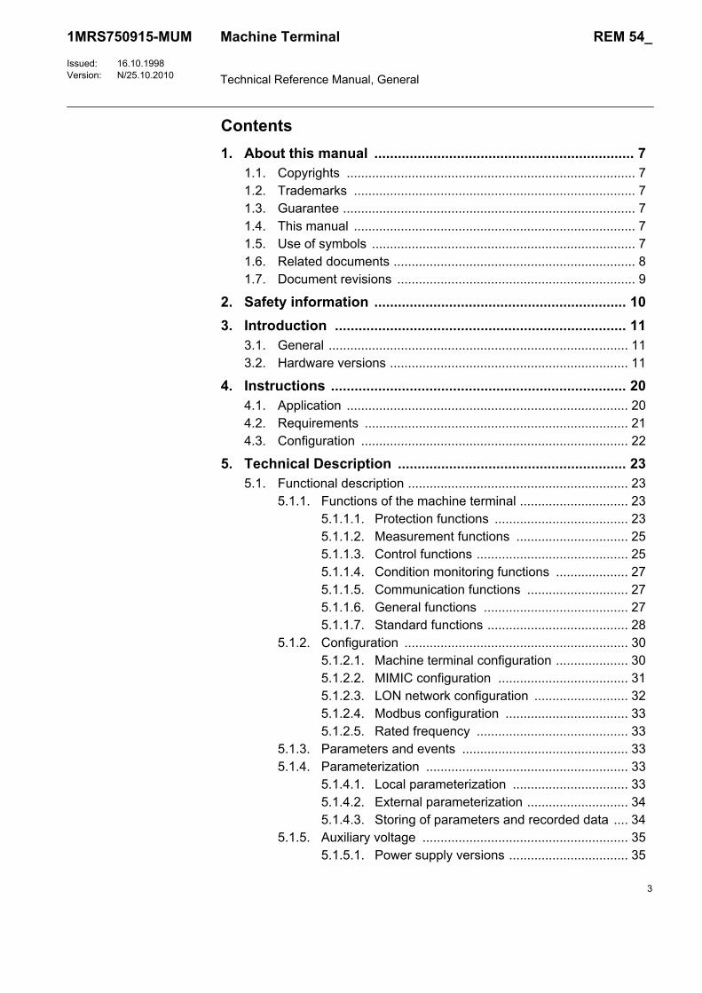
Contents1. About this manual .................................................................. 7
1.1. Copyrights ................................................................................ 71.2. Trademarks .............................................................................. 71.3. Guarantee ................................................................................. 71.4. This manual .............................................................................. 71.5. Use of symbols ......................................................................... 71.6. Related documents ................................................................... 81.7. Document revisions .................................................................. 9
2. Safety information ................................................................ 103. Introduction .......................................................................... 11
3.1. General ................................................................................... 113.2. Hardware versions .................................................................. 11
4. Instructions ........................................................................... 204.1. Application .............................................................................. 204.2. Requirements ......................................................................... 214.3. Configuration .......................................................................... 22
5. Technical Description .......................................................... 235.1. Functional description ............................................................. 23
5.1.1. Functions of the machine terminal .............................. 235.1.1.1. Protection functions ..................................... 235.1.1.2. Measurement functions ............................... 255.1.1.3. Control functions .......................................... 255.1.1.4. Condition monitoring functions .................... 275.1.1.5. Communication functions ............................ 275.1.1.6. General functions ........................................ 275.1.1.7. Standard functions ....................................... 28
5.1.2. Configuration .............................................................. 305.1.2.1. Machine terminal configuration .................... 305.1.2.2. MIMIC configuration .................................... 315.1.2.3. LON network configuration .......................... 325.1.2.4. Modbus configuration .................................. 335.1.2.5. Rated frequency .......................................... 33
5.1.3. Parameters and events .............................................. 335.1.4. Parameterization ........................................................ 33
5.1.4.1. Local parameterization ................................ 335.1.4.2. External parameterization ............................ 345.1.4.3. Storing of parameters and recorded data .... 34
5.1.5. Auxiliary voltage ......................................................... 355.1.5.1. Power supply versions ................................. 35
Machine Terminal Technical Reference Manual, General
4
REM 54_1MRS750915-MUM
Issued: 16.10.1998Version: N/25.10.2010
5.1.5.2. Low auxiliary voltage indication ................... 365.1.5.3. Overtemperature indication ......................... 36
5.1.6. Analog channels ......................................................... 375.1.6.1. Scaling the rated values of the protected unit
for analog channel ....................................... 405.1.6.2. Technical data of the measuring devices .... 415.1.6.3. Calculated analog channels ........................ 43
5.1.7. Digital inputs ............................................................... 435.1.7.1. Filter time of a digital input ........................... 455.1.7.2. Inversion of a digital input ............................ 455.1.7.3. Pulse counters ............................................. 465.1.7.4. Oscillation suppression ................................ 475.1.7.5. Attributes of a digital input for machine terminal
configuration ................................................ 475.1.8. Digital outputs ............................................................. 48
5.1.8.1. High-speed double-pole power outputs (HSPO) ........................................................ 49
5.1.8.2. Single-pole power outputs (PO) ................... 505.1.8.3. Double-pole power outputs (PO) ................. 505.1.8.4. Signal outputs (SO) ..................................... 51
5.1.9. RTD/analog inputs ...................................................... 525.1.9.1. Selection of input signal type ....................... 525.1.9.2. Selection of input signal range .................... 525.1.9.3. Transducer supervision ............................... 545.1.9.4. Signal filtering .............................................. 545.1.9.5. Input scaling/linearization ........................... 545.1.9.6. Transducer connections .............................. 555.1.9.7. Attributes of an RTD/analog input for
machine terminal configuration .................... 575.1.9.8. RTD/analog input configuration example ..... 585.1.9.9. Self-supervision ........................................... 585.1.9.10. Calibration ................................................... 595.1.9.11. RTD temperature vs. resistance .................. 60
5.1.10. Analog outputs ............................................................ 615.1.10.1. Selection of analog output range ................. 615.1.10.2. Attributes of an analog output for machine
terminal configuration .................................. 615.1.10.3. Analog output configuration example .......... 62
5.1.11. Trip circuit supervision ................................................ 635.1.11.1. Configuring the trip circuit supervision
CMTCS_ ...................................................... 645.1.12. Self-supervision (IRF) ................................................. 65
5.1.12.1. Fault indication ............................................ 65
Machine Terminal Technical Reference Manual, General
5
REM 54_1MRS750915-MUM
Issued: 16.10.1998Version: N/25.10.2010
5.1.12.2. Fault codes .................................................. 655.1.13. Serial communication ................................................. 66
5.1.13.1. Serial communication port assignment ........ 665.1.13.2. SPA/Modbus communication on the rear
connector X3.2 ............................................ 665.1.13.3. IEC 61850 communication by using
SPA-ZC 400 on the rear connector X3.2 ..... 675.1.13.4. Profibus-DPV1 communication by using
SPA-ZC 302 on the rear connector X3.2 ..... 675.1.13.5. LON/SPA bus communication on the rear
connector X3.3 ............................................ 675.1.13.6. Front panel optical RS-232 connection for a
PC ................................................................ 675.1.13.7. Communication parameters ......................... 685.1.13.8. Parallel communication support ................... 695.1.13.9. System structure .......................................... 705.1.13.10.LON inputs and outputs via a LON bus ...... 72
5.1.14. Display panel (HMI) .................................................... 745.1.15. Alarm LED indicators .................................................. 75
5.1.15.1. Non-latched alarm ....................................... 765.1.15.2. Latched alarm, steady LED ......................... 775.1.15.3. Latched alarm, blinking LEDs ...................... 775.1.15.4. Interlocking .................................................. 78
5.2. Design description .................................................................. 795.2.1. Technical data ......................................................... 795.2.2. Terminal diagram of REM 543 .................................... 845.2.3. Terminal diagram of REM 545 .................................... 855.2.4. Terminal diagram of the RTD/analog module ............. 865.2.5. Definition of power direction ....................................... 865.2.6. Terminal connections ................................................. 87
6. Service ................................................................................... 907. Ordering Information ........................................................... 91
7.1. Order number ......................................................................... 917.2. Hardware versions of REM 543 and REM 545 ....................... 927.3. Software configuration ............................................................ 92
8. Revision History of REM 54_ ............................................... 938.1. Revision identification ............................................................. 938.2. Release Q4/08 ........................................................................ 93
8.2.1. Changes and additions to earlier released revisions .. 938.2.2. Configuration, setting and SA system tools ................ 93
8.3. Patch release, SW build 4.00 ................................................. 948.3.1. Changes and additions to earlier released revisions .. 94
Machine Terminal Technical Reference Manual, General
6
REM 54_1MRS750915-MUM
Issued: 16.10.1998Version: N/25.10.2010
8.3.2. Configuration, setting and SA system tools ................ 948.4. Release 2.5 ............................................................................ 94
8.4.1. Changes and additions to earlier released revisions .. 948.4.2. Configuration, setting and SA system tools ................ 95
8.5. Release 2.0 ............................................................................ 958.5.1. Changes and additions to earlier released revisions .. 958.5.2. Configuration, setting and SA system tools ................ 98
9. Abbreviations ....................................................................... 9910. Index .................................................................................... 10011.

7
1MRS750915-MUMMachine Terminal Technical Reference Manual, General
REM 54_
1. About this manual
1.1. CopyrightsThe information in this document is subject to change without notice and should not be construed as a commitment by ABB Oy. ABB Oy assumes no responsibility for any errors that may appear in this document.
In no event shall ABB Oy be liable for direct, indirect, special, incidental or consequential damages of any nature or kind arising from the use of this document, nor shall ABB Oy be liable for incidental or consequential damages arising from use of any software or hardware described in this document.
This document and parts thereof must not be reproduced or copied without written permission from ABB Oy, and the contents thereof must not be imparted to a third party nor used for any unauthorized purpose.
The software or hardware described in this document is furnished under a license and may be used, copied, or disclosed only in accordance with the terms of such license.
Copyright © 2008 ABB Oy All rights reserved.
1.2. TrademarksABB is a registered trademark of ABB Group. All other brand or product names mentioned in this document may be trademarks or registered trademarks of their respective holders.
1.3. GuaranteePlease inquire about the terms of guarantee from your nearest ABB representative.
1.4. This manualThis document provides a general description of the machine terminals REM 543 and REM 545, Release 2.5. For more information about the earlier revisions, refer to section “Revision History of REM 54_” on page 93.
For detailed information about the separate function blocks, refer to version 2.2 or later of the CD-ROM Technical Descriptions of Functions (see “Related documents” on page 8).
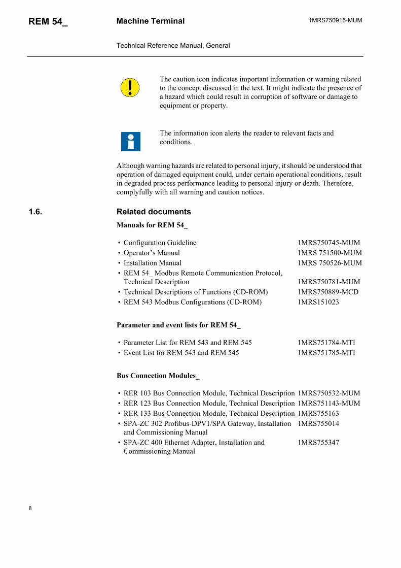
1.5. Use of symbolsThis publication includes the following icons that point out safety-related conditions or other important information:
The electrical warning icon indicates the presence of a hazard which could result in electrical shock.
8
1MRS750915-MUMMachine Terminal Technical Reference Manual, General
REM 54_
Although warning hazards are related to personal injury, it should be understood that operation of damaged equipment could, under certain operational conditions, result in degraded process performance leading to personal injury or death. Therefore, complyfully with all warning and caution notices.
1.6. Related documentsManuals for REM 54_
Parameter and event lists for REM 54_
Bus Connection Modules_
The caution icon indicates important information or warning related to the concept discussed in the text. It might indicate the presence of a hazard which could result in corruption of software or damage to equipment or property.
The information icon alerts the reader to relevant facts and conditions.
• Configuration Guideline 1MRS750745-MUM• Operator’s Manual 1MRS 751500-MUM• Installation Manual 1MRS 750526-MUM• REM 54_ Modbus Remote Communication Protocol,
Technical Description 1MRS750781-MUM• Technical Descriptions of Functions (CD-ROM) 1MRS750889-MCD• REM 543 Modbus Configurations (CD-ROM) 1MRS151023
• Parameter List for REM 543 and REM 545 1MRS751784-MTI• Event List for REM 543 and REM 545 1MRS751785-MTI
• RER 103 Bus Connection Module, Technical Description 1MRS750532-MUM• RER 123 Bus Connection Module, Technical Description 1MRS751143-MUM• RER 133 Bus Connection Module, Technical Description 1MRS755163• SPA-ZC 302 Profibus-DPV1/SPA Gateway, Installation
and Commissioning Manual1MRS755014
• SPA-ZC 400 Ethernet Adapter, Installation and Commissioning Manual
1MRS755347
1MRS750915-MUM REM 54_
9
Machine Terminal Technical Reference Manual, General
Tool-specific manuals
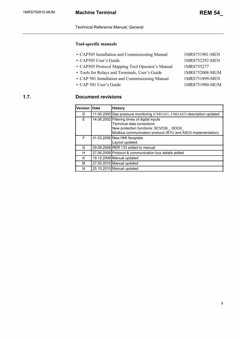
1.7. Document revisions
• CAP505 Installation and Commissioning Manual 1MRS751901-MEN• CAP505 User’s Guide 1MRS752292-MEN• CAP505 Protocol Mapping Tool Operator’s Manual 1MRS755277• Tools for Relays and Terminals, User’s Guide 1MRS752008-MUM• CAP 501 Installation and Commissioning Manual 1MRS751899-MEN• CAP 501 User’s Guide 1MRS751900-MUM
Version Date HistoryD 11.05.2000 Gas pressure monitoring (CMGAS1, CMGAS3) description updatedE 14.06.2002 Filtering times of digital inputs
Technical data correctionsNew protection functions: SCVCSt_, DOC6_Modbus communication protocol (RTU and ASCII implementation)
F 31.03.2006 New HMI faceplateLayout updated
G 29.09.2006 RER 133 added to manualH 27.06.2008 Protocol & communication bus details addedK 19.12.2008 Manual updatedM 27.05.2010 Manual updatedN 25.10.2010 Manual updated
10
1MRS750915-MUMMachine Terminal Technical Reference Manual, General
REM 54_
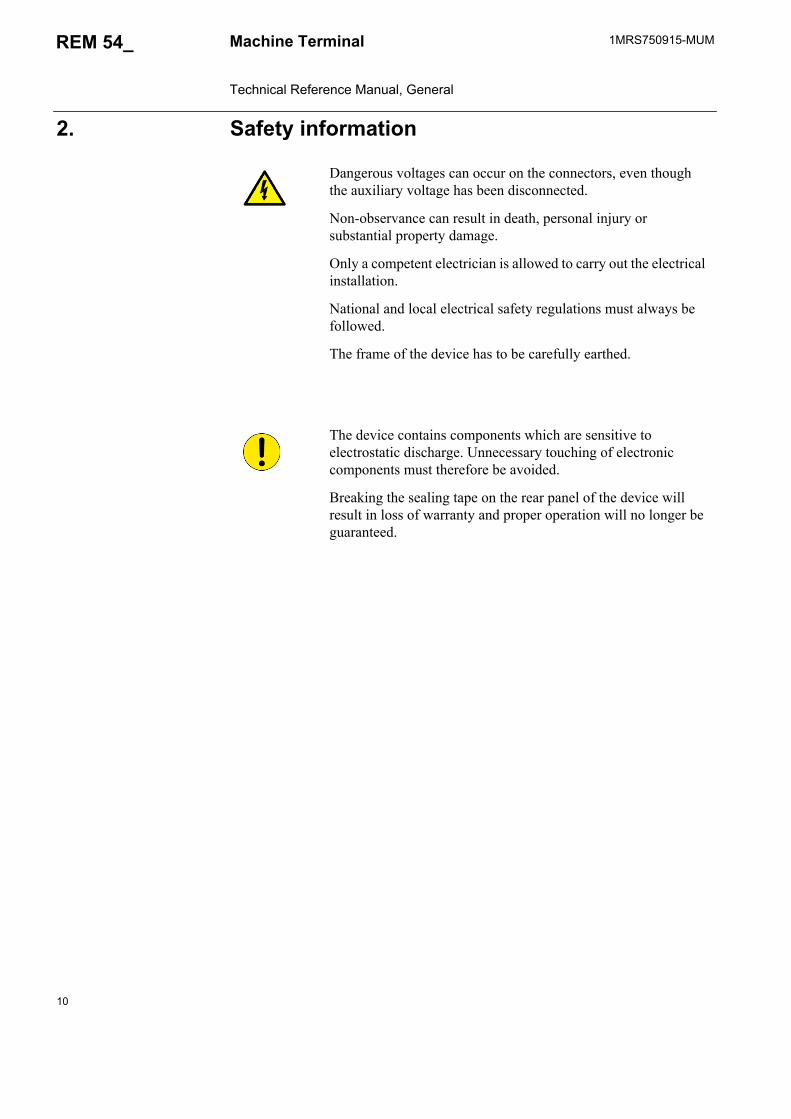
2. Safety information
Dangerous voltages can occur on the connectors, even though the auxiliary voltage has been disconnected.
Non-observance can result in death, personal injury or substantial property damage.
Only a competent electrician is allowed to carry out the electrical installation.
National and local electrical safety regulations must always be followed.
The frame of the device has to be carefully earthed.
The device contains components which are sensitive to electrostatic discharge. Unnecessary touching of electronic components must therefore be avoided.
Breaking the sealing tape on the rear panel of the device will result in loss of warranty and proper operation will no longer be guaranteed.
1MRS750915-MUM REM 54_
11
Machine Terminal Technical Reference Manual, General
3. Introduction
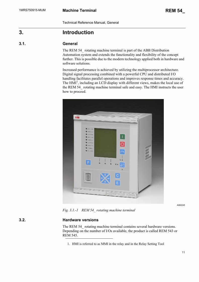
3.1. GeneralThe REM 54_ rotating machine terminal is part of the ABB Distribution Automation system and extends the functionality and flexibility of the concept further. This is possible due to the modern technology applied both in hardware and software solutions.
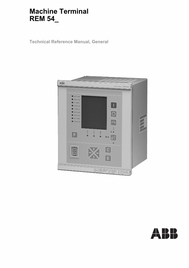
Increased performance is achieved by utilizing the multiprocessor architecture. Digital signal processing combined with a powerful CPU and distributed I/O handling facilitates parallel operations and improves response times and accuracy. The HMI1, including an LCD display with different views, makes the local use of the REM 54_ rotating machine terminal safe and easy. The HMI instructs the user how to proceed.
A060245
Fig. 3.1.-1 REM 54_ rotating machine terminal
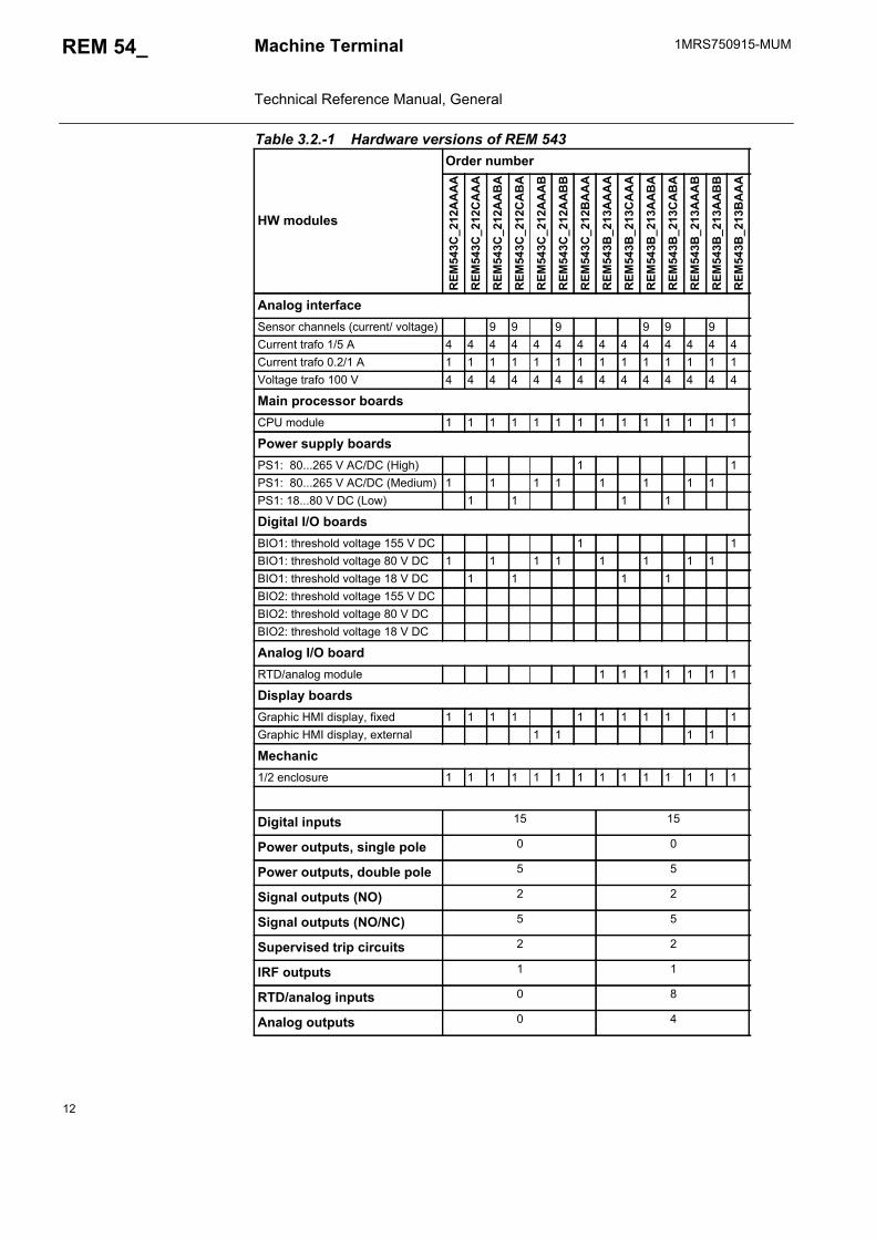
3.2. Hardware versionsThe REM 54_ rotating machine terminal contains several hardware versions. Depending on the number of I/Os available, the product is called REM 543 or REM 545.
1. HMI is referred to as MMI in the relay and in the Relay Setting Tool
12
1MRS750915-MUMMachine Terminal Technical Reference Manual, General
REM 54_
Table 3.2.-1 Hardware versions of REM 543
HW modules
Order number
REM
543C
_212
AA
AA
REM
543C
_212
CA
AA
REM
543C
_212
AA
BA
REM
543C
_212
CA
BA
REM
543C
_212
AA
AB
REM
543C
_212
AA
BB
REM
543C
_212
BA
AA
REM
543B
_213
AA
AA
REM
543B
_213
CA
AA
REM
543B
_213
AA
BA
REM
543B
_213
CA
BA
REM
543B
_213
AA
AB
REM
543B
_213
AA
BB
REM
543B
_213
BA
AA
Analog interfaceSensor channels (current/ voltage) 9 9 9 9 9 9Current trafo 1/5 A 4 4 4 4 4 4 4 4 4 4 4 4 4 4Current trafo 0.2/1 A 1 1 1 1 1 1 1 1 1 1 1 1 1 1Voltage trafo 100 V 4 4 4 4 4 4 4 4 4 4 4 4 4 4
Main processor boardsCPU module 1 1 1 1 1 1 1 1 1 1 1 1 1 1
Power supply boardsPS1: 80...265 V AC/DC (High) 1 1PS1: 80...265 V AC/DC (Medium) 1 1 1 1 1 1 1 1PS1: 18...80 V DC (Low) 1 1 1 1
Digital I/O boardsBIO1: threshold voltage 155 V DC 1 1BIO1: threshold voltage 80 V DC 1 1 1 1 1 1 1 1BIO1: threshold voltage 18 V DC 1 1 1 1BIO2: threshold voltage 155 V DCBIO2: threshold voltage 80 V DCBIO2: threshold voltage 18 V DC
Analog I/O boardRTD/analog module 1 1 1 1 1 1 1
Display boardsGraphic HMI display, fixed 1 1 1 1 1 1 1 1 1 1Graphic HMI display, external 1 1 1 1
Mechanic1/2 enclosure 1 1 1 1 1 1 1 1 1 1 1 1 1 1
Digital inputs 15 15
Power outputs, single pole 0 0
Power outputs, double pole 5 5
Signal outputs (NO) 2 2
Signal outputs (NO/NC) 5 5
Supervised trip circuits 2 2
IRF outputs 1 1
RTD/analog inputs 0 8
Analog outputs 0 4
1MRS750915-MUM REM 54_
13
Machine Terminal Technical Reference Manual, General
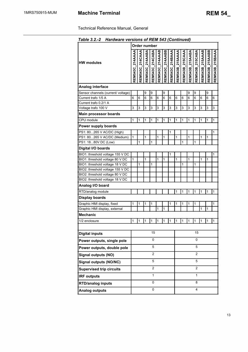
Table 3.2.-2 Hardware versions of REM 543 (Continued)
HW modules
Order number
REM
543C
_214
AA
AA
REM
543C
_214
CA
AA
REM
543C
_214
AA
BA
REM
543C
_214
CA
BA
REM
543C
_214
AA
AB
REM
543C
_214
AA
BB
REM
543C
_214
BA
AA
REM
543B
_215
AA
AA
REM
543B
_215
CA
AA
REM
543B
_215
AA
BA
REM
543B
_215
CA
BA
REM
543B
_215
AA
AB
REM
543B
_215
AA
BB
REM
543B
_215
BA
AA
Analog interfaceSensor channels (current/ voltage) 9 9 9 9 9 9Current trafo 1/5 A 6 6 6 6 6 6 6 6 6 6 6 6 6 6Current trafo 0.2/1 AVoltage trafo 100 V 3 3 3 3 3 3 3 3 3 3 3 3 3 3
Main processor boardsCPU module 1 1 1 1 1 1 1 1 1 1 1 1 1 1
Power supply boardsPS1: 80...265 V AC/DC (High) 1 1PS1: 80...265 V AC/DC (Medium) 1 1 1 1 1 1 1 1PS1: 18...80V DC (Low) 1 1 1 1
Digital I/O boardsBIO1: threshold voltage 155 V DC 1 1BIO1: threshold voltage 80 V DC 1 1 1 1 1 1 1 1BIO1: threshold voltage 18 V DC 1 1 1 1BIO2: threshold voltage 155 V DCBIO2: threshold voltage 80 V DCBIO2: threshold voltage 18 V DC
Analog I/O boardRTD/analog module 1 1 1 1 1 1 1
Display boardsGraphic HMI display, fixed 1 1 1 1 1 1 1 1 1 1Graphic HMI display, external 1 1 1 1
Mechanic1/2 enclosure 1 1 1 1 1 1 1 1 1 1 1 1 1 1
Digital inputs 15 15
Power outputs, single pole 0 0
Power outputs, double pole 5 5
Signal outputs (NO) 2 2
Signal outputs (NO/NC) 5 5
Supervised trip circuits 2 2
IRF outputs 1 1
RTD/analog inputs 0 8
Analog outputs 0 4

14
1MRS750915-MUMMachine Terminal Technical Reference Manual, General
REM 54_
Table 3.2.-3 Hardware versions of REM 543 (Continued)
HW modules
Order number
REM
543C
_216
AA
AA
REM
543C
_216
CA
AA
REM
543C
_216
AA
BA
REM
543C
_216
CA
BA
REM
543C
_216
AA
AB
REM
543C
_216
AA
BB
REM
543C
_216
BA
AA
REM
543B
_217
AA
AA
REM
543B
_217
CA
AA
REM
543B
_217
AA
BA
REM
543B
_217
CA
BA
REM
543B
_217
AA
AB
REM
543B
_217
AA
BB
REM
543B
_217
BA
AA
Analog interfaceSensor channels (current/ voltage) 9 9 9 9 9 9Current trafo 1/5 A 7 7 7 7 7 7 7 7 7 7 7 7 7 7Current trafo 0.2/1 AVoltage trafo 100 V 2 2 2 2 2 2 2 2 2 2 2 2 2 2
Main processor boardsCPU module 1 1 1 1 1 1 1 1 1 1 1 1 1 1
Power supply boardsPS1: 80...265 V AC/DC (High) 1 1PS1: 80...265 V AC/DC (Medium) 1 1 1 1 1 1 1 1PS1: 18...80 V DC (Low) 1 1 1 1
Digital I/O boardsBIO1: threshold voltage 155 V DC 1 1BIO1: threshold voltage 80 V DC 1 1 1 1 1 1 1 1BIO1: threshold voltage 18 V DC 1 1 1 1BIO2: threshold voltage 155 V DCBIO2: threshold voltage 80 V DCBIO2: threshold voltage 18 V DC
Analog I/O boardRTD/analog module 1 1 1 1 1 1 1
Display boardsGraphic HMI display, fixed 1 1 1 1 1 1 1 1 1 1Graphic HMI display, external 1 1 1 1
Mechanic1/2 enclosure 1 1 1 1 1 1 1 1 1 1 1 1 1 1
Digital inputs 15 15
Power outputs, single pole 0 0
Power outputs, double pole 5 5
Signal outputs (NO) 2 2
Signal outputs (NO/NC) 5 5
Supervised trip circuits 2 2
IRF outputs 1 1
RTD/analog inputs 0 8
Analog outputs 0 4
1MRS750915-MUM REM 54_
15
Machine Terminal Technical Reference Manual, General
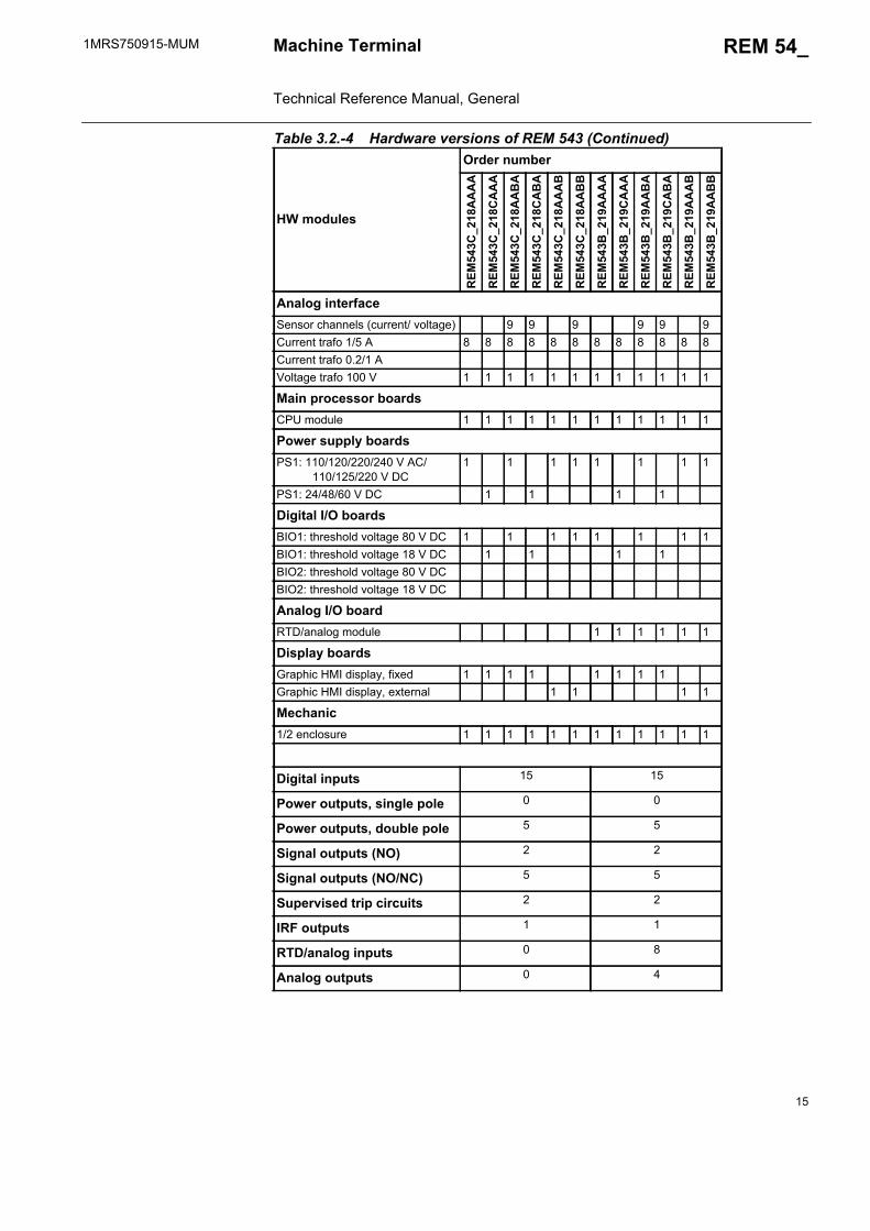
Table 3.2.-4 Hardware versions of REM 543 (Continued)
HW modules
Order number
REM
543C
_218
AA
AA
REM
543C
_218
CA
AA
REM
543C
_218
AA
BA
REM
543C
_218
CA
BA
REM
543C
_218
AA
AB
REM
543C
_218
AA
BB
REM
543B
_219
AA
AA
REM
543B
_219
CA
AA
REM
543B
_219
AA
BA
REM
543B
_219
CA
BA
REM
543B
_219
AA
AB
REM
543B
_219
AA
BB
Analog interfaceSensor channels (current/ voltage) 9 9 9 9 9 9Current trafo 1/5 A 8 8 8 8 8 8 8 8 8 8 8 8Current trafo 0.2/1 AVoltage trafo 100 V 1 1 1 1 1 1 1 1 1 1 1 1
Main processor boardsCPU module 1 1 1 1 1 1 1 1 1 1 1 1
Power supply boardsPS1: 110/120/220/240 V AC/ 110/125/220 V DC
1 1 1 1 1 1 1 1
PS1: 24/48/60 V DC 1 1 1 1
Digital I/O boardsBIO1: threshold voltage 80 V DC 1 1 1 1 1 1 1 1BIO1: threshold voltage 18 V DC 1 1 1 1BIO2: threshold voltage 80 V DCBIO2: threshold voltage 18 V DC
Analog I/O boardRTD/analog module 1 1 1 1 1 1
Display boardsGraphic HMI display, fixed 1 1 1 1 1 1 1 1Graphic HMI display, external 1 1 1 1
Mechanic1/2 enclosure 1 1 1 1 1 1 1 1 1 1 1 1
Digital inputs 15 15
Power outputs, single pole 0 0
Power outputs, double pole 5 5
Signal outputs (NO) 2 2
Signal outputs (NO/NC) 5 5
Supervised trip circuits 2 2
IRF outputs 1 1
RTD/analog inputs 0 8
Analog outputs 0 4

16
1MRS750915-MUMMachine Terminal Technical Reference Manual, General
REM 54_
Table 3.2.-5 Hardware versions of REM 545
HW modules
Order number
REM
545B
_222
AA
AA
REM
545B
_222
CA
AA
REM
545B
_222
AA
BA
REM
545B
_222
CA
BA
REM
545B
_222
AA
AB
REM
545B
_222
AA
BB
REM
545B
_222
BA
AA
REM
545B
_223
AA
AA
REM
545B
_223
CA
AA
REM
545B
_223
AA
BA
REM
545B
_223
CA
BA
REM
545B
_223
AA
AB
REM
545B
_223
AA
BB
REM
545B
_223
BA
AA
Analog interfaceSensor channels (current/ voltage) 9 9 9 9 9 9Current trafo 1/5 A 4 4 4 4 4 4 4 4 4 4 4 4 4 4Current trafo 0.2/1 A 1 1 1 1 1 1 1 1 1 1 1 1 1 1Voltage trafo 100 V 4 4 4 4 4 4 4 4 4 4 4 4 4 4
Main processor boardsCPU module 1 1 1 1 1 1 1 1 1 1 1 1 1 1
Power supply boardsPS1: 80...265 V AC/DC (High) 1 1PS1: 80...265 V AC/DC (Medium) 1 1 1 1 1 1 1 1PS1: 18...80 V DC (Low) 1 1 1 1
Digital I/O boardsBIO1: threshold voltage 155 V DC 1 1BIO1: threshold voltage 80 V DC 1 1 1 1 1 1 1 1BIO1: threshold voltage 18 V DC 1 1 1 1BIO2: thresholld votlage 155 V DC 1 1BIO2: threshold voltage 80 V DC 1 1 1 1 1 1 1 1BIO2: threshold voltage 18 V DC 1 1 1 1
Analog I/O boardRTD/analog module 1 1 1 1 1 1 1
Display boardsGraphic HMI display, fixed 1 1 1 1 1 1 1 1 1 1Graphic HMI display, external 1 1 1 1
Mechanic1/2 enclosure 1 1 1 1 1 1 1 1 1 1 1 1 1 1
Digital inputs 25 25
Power outputs, single pole 2 2
Power outputs, double pole 9 9
Signal outputs (NO) 2 2
Signal outputs (NO/NC) 5 5
Supervised trip circuits 2 2
IRF outputs 1 1
RTD/analog inputs 0 8
Analog outputs 0 4

1MRS750915-MUM REM 54_
17
Machine Terminal Technical Reference Manual, General
Table 3.2.-6 Hardware versions of REM 545 (Continued)
HW modules
Order number
REM
545B
_224
AA
AA
REM
545B
_224
CA
AA
REM
545B
_224
AA
BA
REM
545B
_224
CA
BA
REM
545B
_224
AA
AB
REM
545B
_224
AA
BB
REM
545B
_224
BA
AA
REM
545B
_225
AA
AA
REM
545B
_225
CA
AA
REM
545B
_225
AA
BA
REM
545B
_225
CA
BA
REM
545B
_225
AA
AB
REM
545B
_225
AA
BB
REM
545B
_225
BA
AA
Analog interfaceSensor channels (current/ voltage) 9 9 9 9 9 9Current trafo 1/5 A 6 6 6 6 6 6 6 6 6 6 6 6 6 6Current trafo 0.2/1 AVoltage trafo 100 V 3 3 3 3 3 3 3 3 3 3 3 3 3 3
Main processor boardsCPU module 1 1 1 1 1 1 1 1 1 1 1 1 1 1
Power supply boardsPS1: 80...265 V AC/DC (High) 1 1PS1: 80...265 V AC/DC (Medium) 1 1 1 1 1 1 1 1PS1: 18...80 V DC (Low) 1 1 1 1
Digital I/O boardsBIO1: threshold voltage 155 V DC 1 1BIO1: threshold voltage 80 V DC 1 1 1 1 1 1 1 1BIO1: threshold voltage 18 V DC 1 1 1 1BIO2: threshold voltage 155 V DC 1 1BIO2: threshold voltage 80 V DC 1 1 1 1 1 1 1 1BIO2: threshold voltage 18 V DC 1 1 1 1
Analog I/O boardRTD/analog module 1 1 1 1 1 1 1
Display boardsGraphic HMI display, fixed 1 1 1 1 1 1 1 1 1 1Graphic HMI display, external 1 1 1 1
Mechanic1/2 enclosure 1 1 1 1 1 1 1 1 1 1 1 1 1 1
Digital inputs 25 25
Power outputs, single pole 2 2
Power outputs, double pole 9 9
Signal outputs (NO) 2 2
Signal outputs (NO/NC) 5 5
Supervised trip circuits 2 2
IRF outputs 1 1
RTD/analog inputs 0 8
Analog outputs 0 4
18
1MRS750915-MUMMachine Terminal Technical Reference Manual, General
REM 54_
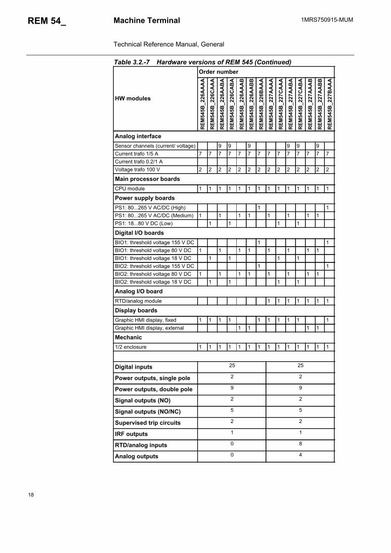
Table 3.2.-7 Hardware versions of REM 545 (Continued)
HW modules
Order number
REM
545B
_226
AA
AA
REM
545B
_226
CA
AA
REM
545B
_226
AA
BA
REM
545B
_226
CA
BA
REM
545B
_226
AA
AB
REM
545B
_226
AA
BB
REM
545B
_226
BA
AA
REM
545B
_227
AA
AA
REM
545B
_227
CA
AA
REM
545B
_227
AA
BA
REM
545B
_227
CA
BA
REM
545B
_227
AA
AB
REM
545B
_227
AA
BB
REM
545B
_227
BA
AA
Analog interfaceSensor channels (current/ voltage) 9 9 9 9 9 9Current trafo 1/5 A 7 7 7 7 7 7 7 7 7 7 7 7 7 7Current trafo 0.2/1 AVoltage trafo 100 V 2 2 2 2 2 2 2 2 2 2 2 2 2 2
Main processor boardsCPU module 1 1 1 1 1 1 1 1 1 1 1 1 1 1
Power supply boardsPS1: 80...265 V AC/DC (High) 1 1PS1: 80...265 V AC/DC (Medium) 1 1 1 1 1 1 1 1PS1: 18...80 V DC (Low) 1 1 1 1
Digital I/O boardsBIO1: threshold voltage 155 V DC 1 1BIO1: threshold voltage 80 V DC 1 1 1 1 1 1 1 1BIO1: threshold voltage 18 V DC 1 1 1 1BIO2: threshold voltage 155 V DC 1 1BIO2: threshold voltage 80 V DC 1 1 1 1 1 1 1 1BIO2: threshold voltage 18 V DC 1 1 1 1
Analog I/O boardRTD/analog module 1 1 1 1 1 1 1
Display boardsGraphic HMI display, fixed 1 1 1 1 1 1 1 1 1 1Graphic HMI display, external 1 1 1 1
Mechanic1/2 enclosure 1 1 1 1 1 1 1 1 1 1 1 1 1 1
Digital inputs 25 25
Power outputs, single pole 2 2
Power outputs, double pole 9 9
Signal outputs (NO) 2 2
Signal outputs (NO/NC) 5 5
Supervised trip circuits 2 2
IRF outputs 1 1
RTD/analog inputs 0 8
Analog outputs 0 4
1MRS750915-MUM REM 54_
19
Machine Terminal Technical Reference Manual, General
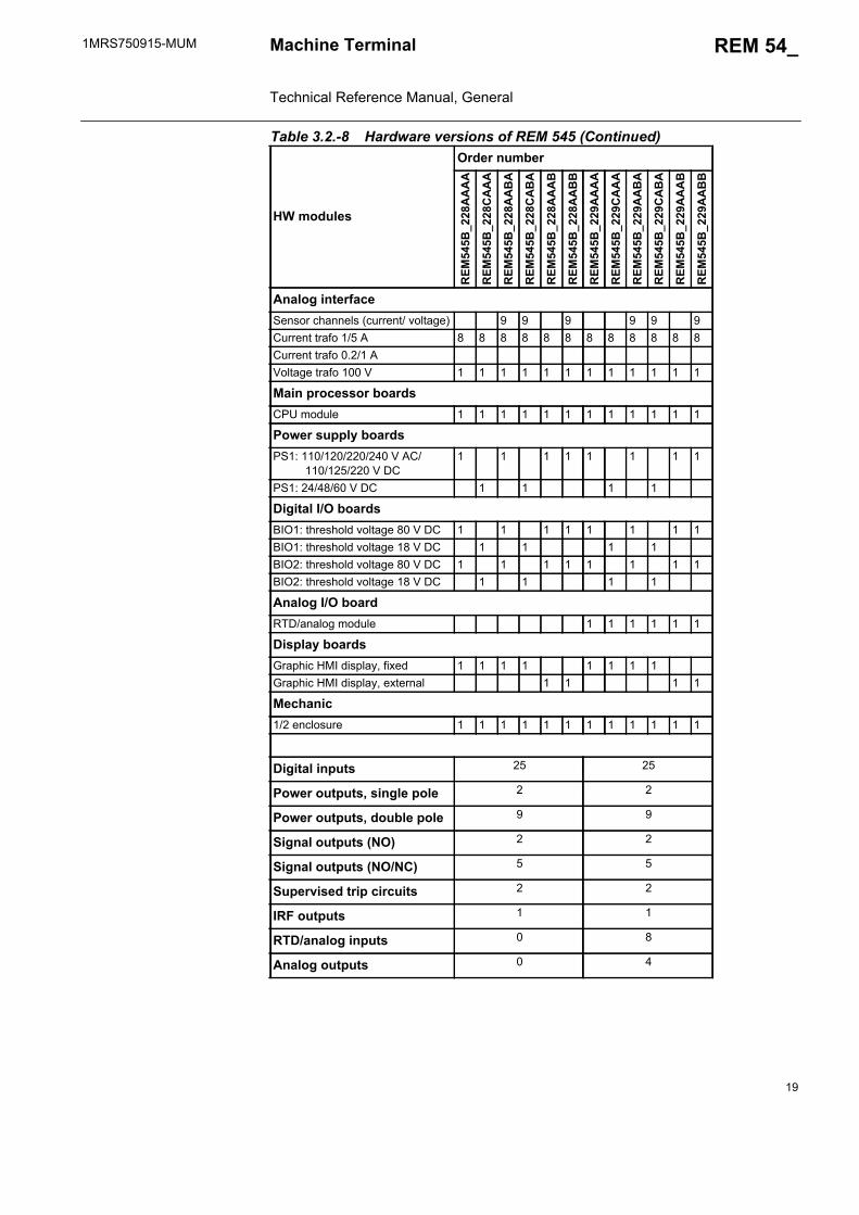
Table 3.2.-8 Hardware versions of REM 545 (Continued)
HW modules
Order number
REM
545B
_228
AA
AA
REM
545B
_228
CA
AA
REM
545B
_228
AA
BA
REM
545B
_228
CA
BA
REM
545B
_228
AA
AB
REM
545B
_228
AA
BB
REM
545B
_229
AA
AA
REM
545B
_229
CA
AA
REM
545B
_229
AA
BA
REM
545B
_229
CA
BA
REM
545B
_229
AA
AB
REM
545B
_229
AA
BB
Analog interfaceSensor channels (current/ voltage) 9 9 9 9 9 9Current trafo 1/5 A 8 8 8 8 8 8 8 8 8 8 8 8Current trafo 0.2/1 AVoltage trafo 100 V 1 1 1 1 1 1 1 1 1 1 1 1
Main processor boardsCPU module 1 1 1 1 1 1 1 1 1 1 1 1
Power supply boardsPS1: 110/120/220/240 V AC/ 110/125/220 V DC
1 1 1 1 1 1 1 1
PS1: 24/48/60 V DC 1 1 1 1
Digital I/O boardsBIO1: threshold voltage 80 V DC 1 1 1 1 1 1 1 1BIO1: threshold voltage 18 V DC 1 1 1 1BIO2: threshold voltage 80 V DC 1 1 1 1 1 1 1 1BIO2: threshold voltage 18 V DC 1 1 1 1
Analog I/O boardRTD/analog module 1 1 1 1 1 1
Display boardsGraphic HMI display, fixed 1 1 1 1 1 1 1 1Graphic HMI display, external 1 1 1 1
Mechanic1/2 enclosure 1 1 1 1 1 1 1 1 1 1 1 1
Digital inputs 25 25
Power outputs, single pole 2 2
Power outputs, double pole 9 9
Signal outputs (NO) 2 2
Signal outputs (NO/NC) 5 5
Supervised trip circuits 2 2
IRF outputs 1 1
RTD/analog inputs 0 8
Analog outputs 0 4
20
1MRS750915-MUMMachine Terminal Technical Reference Manual, General
REM 54_
4. Instructions
4.1. ApplicationThe REM 54_ rotating machine terminals (referred to as “machine terminals” further on) are designed to be used as the main protection system of generator and generator-transformer units in small and medium-power diesel, hydroelectric and steam power plants, etc. The protection of large and/or important MV synchronous and asynchronous motors used e.g. in pumps, mills and crushers during start-up and normal run forms another application area.
The functionality available for the machine terminals depends on the selected functionality level (refer to section “Ordering Information” on page 91) and is also tied to the hardware configuration. The desired functions can be activated from a wide range of protection, control, measurement, condition monitoring, general and communication functions within the scope of I/O connections, considering the total CPU load. Compared to the traditional use of separate products, the combination of desired functions provides cost-effective solutions and, together with the relay configuration (IEC 61131-3 standard), allows the machine terminals to be easily adapted to different kinds of applications.
By means of the graphic HMI display, the control functions in the machine terminal indicate the status of disconnectors or circuit breakers locally. Further, the machine terminal allows status information from the circuit breakers and the disconnectors to be transmitted to the remote control system. Controllable objects, such as CBs, can be opened and closed over the remote control system. Status information and control signals are transmitted over the serial bus. Local control is also possible via the push-buttons on the front panel of the machine terminal.
The protection functions of the machine terminals are designed for selective short-circuit and earth-fault protection of rotating machines. Further, unlike most other power system components, rotating machines also need protection against abnormal operating conditions such as overcurrent, unbalanced load, overtemperature, over- and undervoltage, over- and underexcitation, over- and underfrequency and generator motoring. Also, underimpedance function is provided for line back-up. Furthermore, stall protection and cumulative start-up counter are provided for motor protection start-up supervision.
The machine terminals measure phase currents, phase-to-phase or phase-to-earth voltages, neutral current, residual voltage, frequency and power factors. Active and reactive power is calculated from measured currents and voltages. Energy can be calculated on the basis of the measured power. The measured values can be indicated locally and remotely as scaled primary values.
In addition to protection, measurement, control, condition monitoring and general functions, the machine terminals are provided with a large amount of PLC functions allowing several automation and sequence logic functions needed for substation automation to be integrated into one unit. The data communication properties include SPA bus, Modbus or LON bus communication with higher-level equipment. Further, LON communication, together with PLC functions, minimizes the need for hardwiring between the machine terminals.
1MRS750915-MUM REM 54_
21
Machine Terminal Technical Reference Manual, General
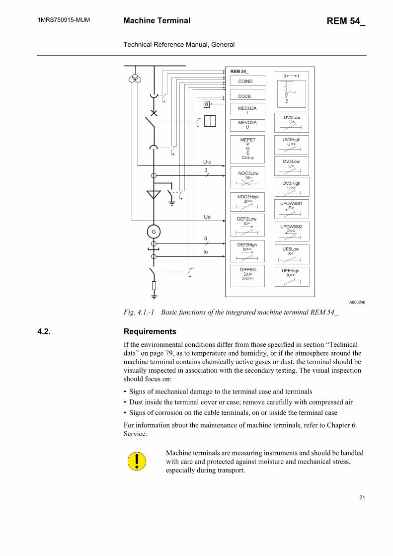
A060246
Fig. 4.1.-1 Basic functions of the integrated machine terminal REM 54_
4.2. RequirementsIf the environmental conditions differ from those specified in section “Technical data” on page 79, as to temperature and humidity, or if the atmosphere around the machine terminal contains chemically active gases or dust, the terminal should be visually inspected in association with the secondary testing. The visual inspection should focus on:
• Signs of mechanical damage to the terminal case and terminals• Dust inside the terminal cover or case; remove carefully with compressed air• Signs of corrosion on the cable terminals, on or inside the terminal case
For information about the maintenance of machine terminals, refer to Chapter 6. Service.
��
�
�
�
�����
�
����
����
����
�������
�����
�
��
��
�������������
�
��������
����� !���
����������
������ !����
����"
��� !""
������
���� !��
��#�$%���
��#�$%����
�������������
�
�����&"
���� !&""
�������
Machine terminals are measuring instruments and should be handled with care and protected against moisture and mechanical stress, especially during transport.

22
1MRS750915-MUMMachine Terminal Technical Reference Manual, General
REM 54_
4.3. ConfigurationThe REM 54_ machine terminals are adapted to specific applications by using the Relay Configuration Tool included in the CAP 505 tools. This tool is used for configuring the basic terminal, protection and logic function blocks, control and measurement functions, timers and other functional elements included in the logic functions category (refer to section “Machine terminal configuration” on page 30).
The MIMIC picture, alarm texts and LED indicators are configured with the Relay Mimic Editor (refer to section “MIMIC configuration” on page 31).
The configuration of LON network is described in section “LON network configuration” on page 32. If the application includes no horizontal communication, network variables are not needed and the section about LON network configuration is thus not relevant.
The configuration of Modbus network is described in section “Modbus configuration” on page 33.
The configuration procedure starts by configuring the functions of protection, control, condition monitoring, measurement and logics.
For more detailed information about the configuration, refer to the Configuration Guideline and the tool-specific manuals (see “Related documents” on page 8).
For more information about the Modbus configurations, refer to the CD-ROM REM 543 Modbus Configurations (see “Related documents” on page 8).

1MRS750915-MUM REM 54_
23
Machine Terminal Technical Reference Manual, General
5. Technical Description
5.1. Functional description
5.1.1. Functions of the machine terminalThe functions of REM 54_ machine terminal are categorized as:
• protection functions• measurement functions• control functions• condition monitoring functions• communication functions• general functions• standard functions
The functions are further divided to two subsets that correspond to different functionality levels (refer to section “Ordering Information” on page 91).
5.1.1.1. Protection functionsProtection is one of the most important functions of the machine terminal. The protection function blocks (e.g. NOC3Low) are independent of each other and have their own setting groups, data recording, etc. The non-directional overcurrent protection, for example, includes the three stages NOC3Low, NOC3High and NOC3Inst, each with independent protection functions.
Either Rogowski coils or conventional current transformers can be used for protection functions based on current measurement (overcurrent). Correspondingly, voltage dividers or voltage transformers are used for protection functions based on voltage measurement (overvoltage).
The protection function blocks are documented on the CD-ROM Technical Descriptions of Functions.
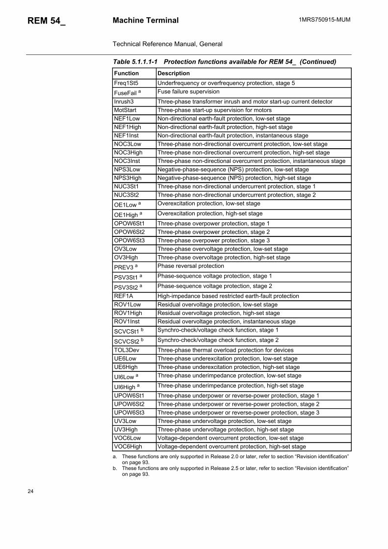
Table 5.1.1.1-1 Protection functions available for REM 54_
Function DescriptionDEF2Low Directional earth-fault protection, low-set stageDEF2High Directional earth-fault protection, high-set stageDEF2Inst Directional earth-fault protection, instantaneous stage
Diff3 a High-impedance or flux-balance based differential protection for generators and motors
Diff6G Stabilized three-phase differential protection for generators
DOC6Low b Three-phase directional O/C function, low-set stage I> ->
DOC6High b Three-phase directional O/C function, high-set stage I>> ->
DOC6Inst b Three-phase directional O/C function, instantaneous stage I>>> ->
Freq1St1 Underfrequency or overfrequency protection, stage 1Freq1St2 Underfrequency or overfrequency protection, stage 2Freq1St3 Underfrequency or overfrequency protection, stage 3Freq1St4 Underfrequency or overfrequency protection, stage 4
24
1MRS750915-MUMMachine Terminal Technical Reference Manual, General
REM 54_
Freq1St5 Underfrequency or overfrequency protection, stage 5
FuseFail a Fuse failure supervision
Inrush3 Three-phase transformer inrush and motor start-up current detectorMotStart Three-phase start-up supervision for motorsNEF1Low Non-directional earth-fault protection, low-set stageNEF1High Non-directional earth-fault protection, high-set stageNEF1Inst Non-directional earth-fault protection, instantaneous stageNOC3Low Three-phase non-directional overcurrent protection, low-set stageNOC3High Three-phase non-directional overcurrent protection, high-set stageNOC3Inst Three-phase non-directional overcurrent protection, instantaneous stageNPS3Low Negative-phase-sequence (NPS) protection, low-set stageNPS3High Negative-phase-sequence (NPS) protection, high-set stageNUC3St1 Three-phase non-directional undercurrent protection, stage 1NUC3St2 Three-phase non-directional undercurrent protection, stage 2
OE1Low a Overexcitation protection, low-set stage
OE1High a Overexcitation protection, high-set stage
OPOW6St1 Three-phase overpower protection, stage 1OPOW6St2 Three-phase overpower protection, stage 2OPOW6St3 Three-phase overpower protection, stage 3OV3Low Three-phase overvoltage protection, low-set stageOV3High Three-phase overvoltage protection, high-set stage
PREV3 a Phase reversal protection
PSV3St1 a Phase-sequence voltage protection, stage 1
PSV3St2 a Phase-sequence voltage protection, stage 2
REF1A High-impedance based restricted earth-fault protectionROV1Low Residual overvoltage protection, low-set stageROV1High Residual overvoltage protection, high-set stageROV1Inst Residual overvoltage protection, instantaneous stage
SCVCSt1 b Synchro-check/voltage check function, stage 1
SCVCSt2 b Synchro-check/voltage check function, stage 2
TOL3Dev Three-phase thermal overload protection for devicesUE6Low Three-phase underexcitation protection, low-set stageUE6High Three-phase underexcitation protection, high-set stage
UI6Low a Three-phase underimpedance protection, low-set stage
UI6High a Three-phase underimpedance protection, high-set stage
UPOW6St1 Three-phase underpower or reverse-power protection, stage 1UPOW6St2 Three-phase underpower or reverse-power protection, stage 2UPOW6St3 Three-phase underpower or reverse-power protection, stage 3UV3Low Three-phase undervoltage protection, low-set stageUV3High Three-phase undervoltage protection, high-set stageVOC6Low Voltage-dependent overcurrent protection, low-set stageVOC6High Voltage-dependent overcurrent protection, high-set stage
a. These functions are only supported in Release 2.0 or later, refer to section “Revision identification” on page 93.
b. These functions are only supported in Release 2.5 or later, refer to section “Revision identification” on page 93.
Table 5.1.1.1-1 Protection functions available for REM 54_ (Continued)
Function Description
1MRS750915-MUM REM 54_
25
Machine Terminal Technical Reference Manual, General
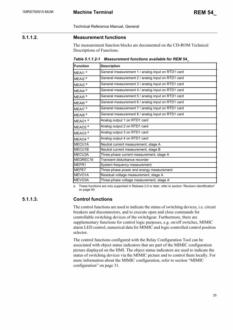
5.1.1.2. Measurement functionsThe measurement function blocks are documented on the CD-ROM Technical Descriptions of Functions.
5.1.1.3. Control functionsThe control functions are used to indicate the status of switching devices, i.e. circuit breakers and disconnectors, and to execute open and close commands for controllable switching devices of the switchgear. Furthermore, there are supplementary functions for control logic purposes, e.g. on/off switches, MIMIC alarm LED control, numerical data for MIMIC and logic controlled control position selector.
The control functions configured with the Relay Configuration Tool can be associated with object status indicators that are part of the MIMIC configuration picture displayed on the HMI. The object status indicators are used to indicate the status of switching devices via the MIMIC picture and to control them locally. For more information about the MIMIC configuration, refer to section “MIMIC configuration” on page 31.
Table 5.1.1.2-1 Measurement functions available for REM 54_
Function Description
MEAI1 a
a. These functions are only supported in Release 2.0 or later, refer to section “Revision identification” on page 93.
General measurement 1 / analog input on RTD1 card
MEAI2 a General measurement 2 / analog input on RTD1 card
MEAI3 a General measurement 3 / analog input on RTD1 card
MEAI4 a General measurement 4 / analog input on RTD1 card
MEAI5 a General measurement 5 / analog input on RTD1 card
MEAI6 a General measurement 6 / analog input on RTD1 card
MEAI7 a General measurement 7 / analog input on RTD1 card
MEAI8 a General measurement 8 / analog input on RTD1 card
MEAO1 a Analog output 1 on RTD1 card
MEAO2 a Analog output 2 on RTD1 card
MEAO3 a Analog output 3 on RTD1 card
MEAO4 a Analog output 4 on RTD1 card
MECU1A Neutral current measurement, stage AMECU1B Neutral current measurement, stage BMECU3A Three-phase current measurement, stage AMEDREC16 Transient disturbance recorderMEFR1 System frequency measurementMEPE7 Three-phase power and energy measurementMEVO1A Residual voltage measurement, stage AMEVO3A Three-phase voltage measurement, stage A
26
1MRS750915-MUMMachine Terminal Technical Reference Manual, General
REM 54_
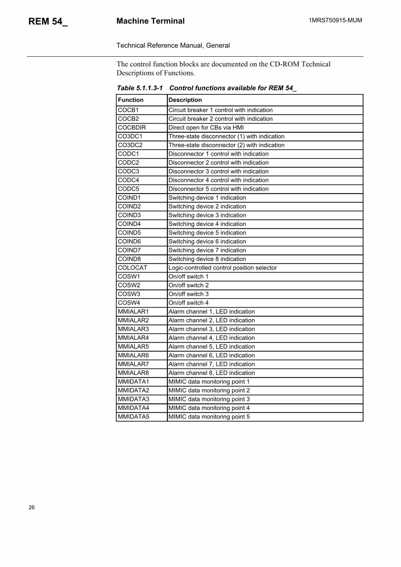
The control function blocks are documented on the CD-ROM Technical Descriptions of Functions.
Table 5.1.1.3-1 Control functions available for REM 54_
Function DescriptionCOCB1 Circuit breaker 1 control with indicationCOCB2 Circuit breaker 2 control with indicationCOCBDIR Direct open for CBs via HMICO3DC1 Three-state disconnector (1) with indicationCO3DC2 Three-state disconnector (2) with indicationCODC1 Disconnector 1 control with indicationCODC2 Disconnector 2 control with indicationCODC3 Disconnector 3 control with indicationCODC4 Disconnector 4 control with indicationCODC5 Disconnector 5 control with indicationCOIND1 Switching device 1 indicationCOIND2 Switching device 2 indication COIND3 Switching device 3 indicationCOIND4 Switching device 4 indication COIND5 Switching device 5 indicationCOIND6 Switching device 6 indication COIND7 Switching device 7 indication COIND8 Switching device 8 indication COLOCAT Logic-controlled control position selectorCOSW1 On/off switch 1 COSW2 On/off switch 2COSW3 On/off switch 3COSW4 On/off switch 4MMIALAR1 Alarm channel 1, LED indicationMMIALAR2 Alarm channel 2, LED indicationMMIALAR3 Alarm channel 3, LED indicationMMIALAR4 Alarm channel 4, LED indicationMMIALAR5 Alarm channel 5, LED indicationMMIALAR6 Alarm channel 6, LED indicationMMIALAR7 Alarm channel 7, LED indicationMMIALAR8 Alarm channel 8, LED indicationMMIDATA1 MIMIC data monitoring point 1MMIDATA2 MIMIC data monitoring point 2MMIDATA3 MIMIC data monitoring point 3MMIDATA4 MIMIC data monitoring point 4MMIDATA5 MIMIC data monitoring point 5
1MRS750915-MUM REM 54_
27
Machine Terminal Technical Reference Manual, General
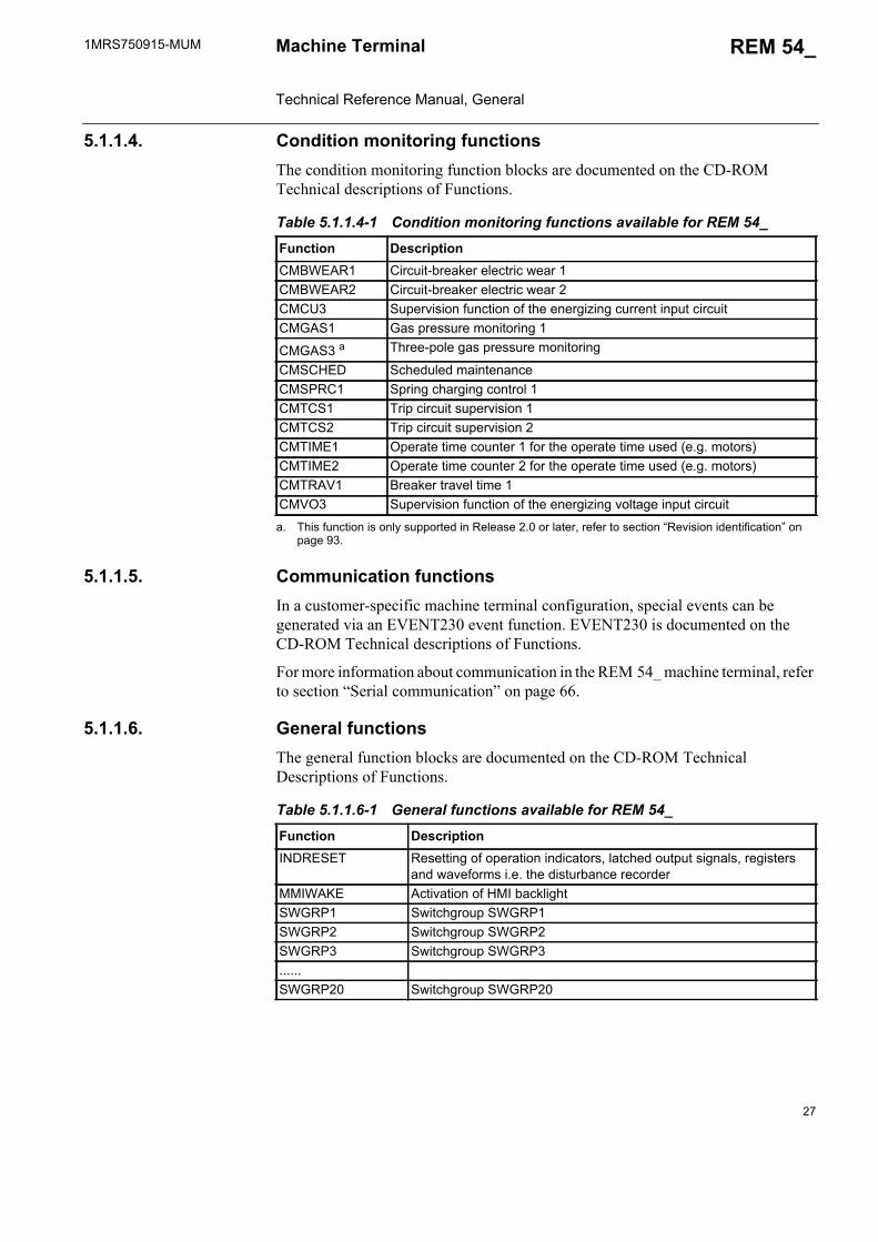
5.1.1.4. Condition monitoring functionsThe condition monitoring function blocks are documented on the CD-ROM Technical descriptions of Functions.
5.1.1.5. Communication functionsIn a customer-specific machine terminal configuration, special events can be generated via an EVENT230 event function. EVENT230 is documented on the CD-ROM Technical descriptions of Functions.
For more information about communication in the REM 54_ machine terminal, refer to section “Serial communication” on page 66.
5.1.1.6. General functionsThe general function blocks are documented on the CD-ROM Technical Descriptions of Functions.
Table 5.1.1.4-1 Condition monitoring functions available for REM 54_
Function Description CMBWEAR1 Circuit-breaker electric wear 1CMBWEAR2 Circuit-breaker electric wear 2CMCU3 Supervision function of the energizing current input circuitCMGAS1 Gas pressure monitoring 1
CMGAS3 a
a. This function is only supported in Release 2.0 or later, refer to section “Revision identification” on page 93.
Three-pole gas pressure monitoring
CMSCHED Scheduled maintenanceCMSPRC1 Spring charging control 1CMTCS1 Trip circuit supervision 1CMTCS2 Trip circuit supervision 2CMTIME1 Operate time counter 1 for the operate time used (e.g. motors)CMTIME2 Operate time counter 2 for the operate time used (e.g. motors)CMTRAV1 Breaker travel time 1CMVO3 Supervision function of the energizing voltage input circuit
Table 5.1.1.6-1 General functions available for REM 54_
Function DescriptionINDRESET Resetting of operation indicators, latched output signals, registers
and waveforms i.e. the disturbance recorderMMIWAKE Activation of HMI backlightSWGRP1 Switchgroup SWGRP1SWGRP2 Switchgroup SWGRP2SWGRP3 Switchgroup SWGRP3......SWGRP20 Switchgroup SWGRP20
28
1MRS750915-MUMMachine Terminal Technical Reference Manual, General
REM 54_
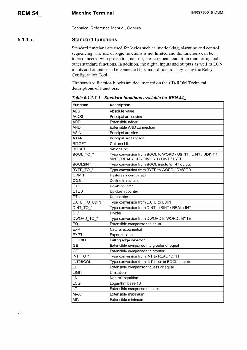
5.1.1.7. Standard functionsStandard functions are used for logics such as interlocking, alarming and control sequencing. The use of logic functions is not limited and the functions can be interconnected with protection, control, measurement, condition monitoring and other standard functions. In addition, the digital inputs and outputs as well as LON inputs and outputs can be connected to standard functions by using the Relay Configuration Tool.
The standard function blocks are documented on the CD-ROM Technical descriptions of Functions.
Table 5.1.1.7-1 Standard functions available for REM 54_
Function DescriptionABS Absolute valueACOS Principal arc cosineADD Extensible adderAND Extensible AND connectionASIN Principal arc sineATAN Principal arc tangentBITGET Get one bitBITSET Set one bitBOOL_TO_* Type conversion from BOOL to WORD / USINT / UINT / UDINT /
SINT / REAL / INT / DWORD / DINT / BYTEBOOL2INT Type conversion from BOOL inputs to INT output BYTE_TO_* Type conversion from BYTE to WORD / DWORDCOMH Hysteresis comparatorCOS Cosine in radiansCTD Down-counterCTUD Up-down counterCTU Up-counterDATE_TO_UDINT Type conversion from DATE to UDINTDINT_TO_* Type conversion from DINT to SINT / REAL / INTDIV DividerDWORD_TO_* Type conversion from DWORD to WORD / BYTEEQ Extensible comparison to equalEXP Natural exponentialEXPT ExponentiationF_TRIG Falling edge detectorGE Extensible comparison to greater or equalGT Extensible comparison to greaterINT_TO_* Type conversion from INT to REAL / DINTINT2BOOL Type conversion from INT input to BOOL outputsLE Extensible comparison to less or equalLIMIT LimitationLN Natural logarithmLOG Logarithm base 10LT Extensible comparison to lessMAX Extensible maximumMIN Extensible minimum

1MRS750915-MUM REM 54_
29
Machine Terminal Technical Reference Manual, General
MOD ModuloMOVE MoveMUL Extensible multiplierMUX Extensible multiplexerNE Comparison to greater or lessNOT ComplementOR Extensible OR connectionR_TRIG Rising edge detectorREAL_TO_* Type conversion from REAL to USINT / UINT / UDINT / SINT / INT /
DINTROL Rotate to leftROR Rotate to rightRS Reset dominant bistable function blockRS_D Reset dominant bistable function block with data inputSEL Binary selectionSHL Bit-shift to leftSHR Bit-shift to rightSIN Sine in radiansSINT_TO_* Type conversion from SINT to REAL / INT / DINTSUB SubtractorSQRT Square rootSR Set dominant bistable function blockXOR Extensible exclusive OR connectionTAN Tangent in radiansTIME_TO_* Type conversion from TIME to UDINT / TOD / REALTOD_TO_* Type conversion from TOD to UDINT / TIME / REALTOF Off-delay timerTON On-delay timerTP PulseTRUNC_* Truncation toward zeroUDINT_TO_* Type conversion from UDINT to USINT / UINT / REALUINT_TO_* Type conversion from UINT to USINT / UDINT / REAL / BOOLUSINT_TO_* Type conversion from USINT to UINT / UDINT / REALWORD_TO_* Type conversion from WORD to DWORD / BYTE
Table 5.1.1.7-1 Standard functions available for REM 54_ (Continued)
Function Description

30
1MRS750915-MUMMachine Terminal Technical Reference Manual, General
REM 54_
5.1.2. Configuration
5.1.2.1. Machine terminal configurationThe Relay Configuration Tool is based on the IEC 61131-3 standard. The standard defines the programming language used for configuration. The programmable system of the REM 54_ machine terminals allows the output contacts to be operated in accordance with the state of the logic inputs and the outputs of the protection, control, measurement and condition monitoring functions. The PLC functions (e.g. interlocking and alarm logic) are programmed with Boolean functions, timers, counters, comparators and flip-flops. The program is written in a function block diagram language by using the configuration software.
After the configuration has been built and successfully compiled, and the MIMIC configuration has been designed, the Relay Configuration Tool project (RCT project in CAP 505) including the relay configuration and MIMIC configuration can be downloaded to the relay with the Relay Download Tool. The project can also be uploaded from the machine terminal with the same tool1. However, the relay configuration, the RCT project and the MIMIC configuration are saved in a non-volatile memory only after they have been stored via the parameter Store. To activate new configurations, the machine terminal should be reset via the parameter Software reset. These parameters can be found in the menu Configuration/General. Likewise, the storing and the resetting can be done by using the relay command buttons Store and Reset in the Relay Download Tool.
A050238
Fig. 5.1.2.1.-1 Example of a terminal configuration with the RCT
1. This function is only supported in Release 2.0 or later.
1MRS750915-MUM REM 54_
31
Machine Terminal Technical Reference Manual, General
For more information about the configuration and the Relay Configuration Tool refer to the Configuration Guideline and the tool manuals (see “Related documents” on page 8).
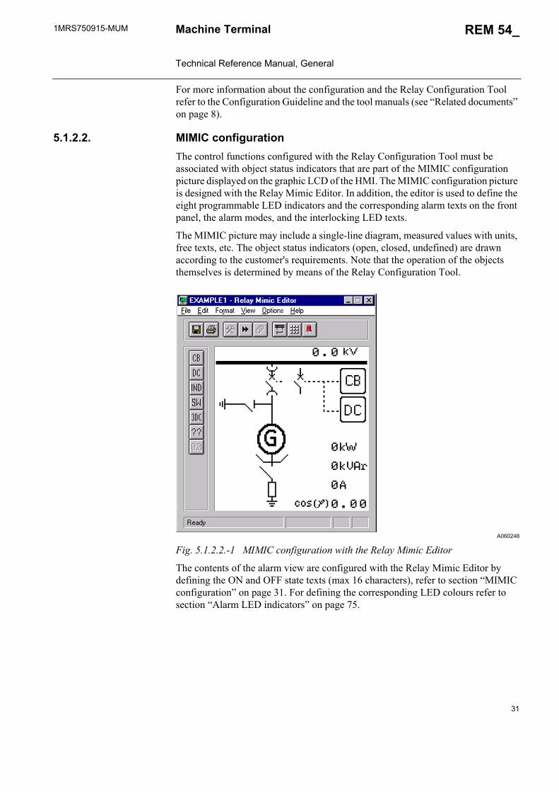
5.1.2.2. MIMIC configurationThe control functions configured with the Relay Configuration Tool must be associated with object status indicators that are part of the MIMIC configuration picture displayed on the graphic LCD of the HMI. The MIMIC configuration picture is designed with the Relay Mimic Editor. In addition, the editor is used to define the eight programmable LED indicators and the corresponding alarm texts on the front panel, the alarm modes, and the interlocking LED texts.
The MIMIC picture may include a single-line diagram, measured values with units, free texts, etc. The object status indicators (open, closed, undefined) are drawn according to the customer's requirements. Note that the operation of the objects themselves is determined by means of the Relay Configuration Tool.
A060248
Fig. 5.1.2.2.-1 MIMIC configuration with the Relay Mimic Editor
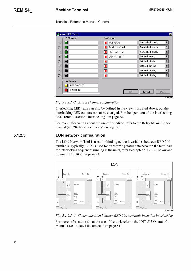
The contents of the alarm view are configured with the Relay Mimic Editor by defining the ON and OFF state texts (max 16 characters), refer to section “MIMIC configuration” on page 31. For defining the corresponding LED colours refer to section “Alarm LED indicators” on page 75.
32
1MRS750915-MUMMachine Terminal Technical Reference Manual, General
REM 54_
A060249
Fig. 5.1.2.2.-2 Alarm channel configuration
Interlocking LED texts can also be defined in the view illustrated above, but the interlocking LED colours cannot be changed. For the operation of the interlocking LED, refer to section “Interlocking” on page 78.
For more information about the use of the editor, refer to the Relay Mimic Editor manual (see “Related documents” on page 8).
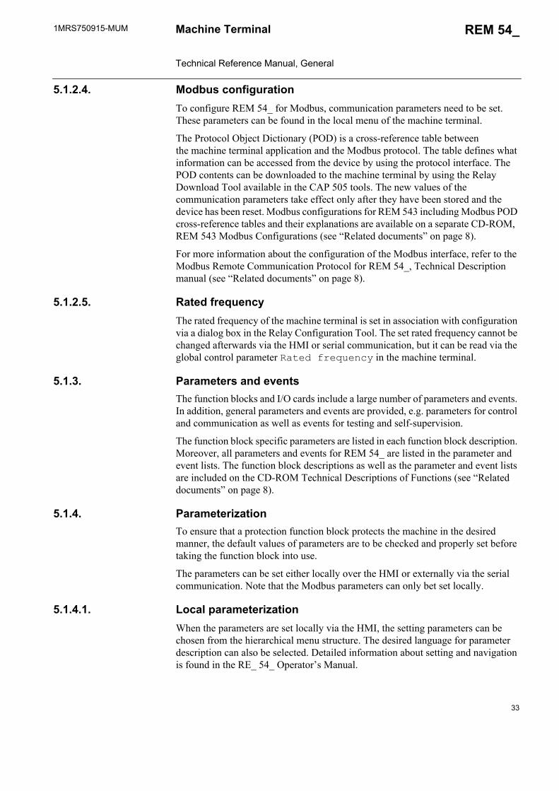
5.1.2.3. LON network configurationThe LON Network Tool is used for binding network variables between RED 500 terminals. Typically, LON is used for transferring status data between the terminals for interlocking sequences running in the units, refer to chapter 5.1.2.3.-1 below and Figure 5.1.13.10.-1 on page 73.
A050183
Fig. 5.1.2.3.-1 Communication between RED 500 terminals in station interlocking
For more information about the use of the tool, refer to the LNT 505 Operator’s Manual (see “Related documents” on page 8).
��
������
��� ���
������ ������
��
������
��� ���
������ ������
��
������
��� ���
������ ������
���
������������
��������
������
�������
����
�������
������������
��������
������
�������
����
�������
������������
��������
������
�������
����
�������
�� ��� �� ��!� �� ��� �� ��!� �� ��� �� ��!�
�"� �"� �"�
1MRS750915-MUM REM 54_
33
Machine Terminal Technical Reference Manual, General
5.1.2.4. Modbus configurationTo configure REM 54_ for Modbus, communication parameters need to be set. These parameters can be found in the local menu of the machine terminal.
The Protocol Object Dictionary (POD) is a cross-reference table between the machine terminal application and the Modbus protocol. The table defines what information can be accessed from the device by using the protocol interface. The POD contents can be downloaded to the machine terminal by using the Relay Download Tool available in the CAP 505 tools. The new values of the communication parameters take effect only after they have been stored and the device has been reset. Modbus configurations for REM 543 including Modbus POD cross-reference tables and their explanations are available on a separate CD-ROM, REM 543 Modbus Configurations (see “Related documents” on page 8).
For more information about the configuration of the Modbus interface, refer to the Modbus Remote Communication Protocol for REM 54_, Technical Description manual (see “Related documents” on page 8).
5.1.2.5. Rated frequencyThe rated frequency of the machine terminal is set in association with configuration via a dialog box in the Relay Configuration Tool. The set rated frequency cannot be changed afterwards via the HMI or serial communication, but it can be read via the global control parameter Rated frequency in the machine terminal.
5.1.3. Parameters and eventsThe function blocks and I/O cards include a large number of parameters and events. In addition, general parameters and events are provided, e.g. parameters for control and communication as well as events for testing and self-supervision.
The function block specific parameters are listed in each function block description. Moreover, all parameters and events for REM 54_ are listed in the parameter and event lists. The function block descriptions as well as the parameter and event lists are included on the CD-ROM Technical Descriptions of Functions (see “Related documents” on page 8).
5.1.4. ParameterizationTo ensure that a protection function block protects the machine in the desired manner, the default values of parameters are to be checked and properly set before taking the function block into use.
The parameters can be set either locally over the HMI or externally via the serial communication. Note that the Modbus parameters can only bet set locally.
5.1.4.1. Local parameterizationWhen the parameters are set locally via the HMI, the setting parameters can be chosen from the hierarchical menu structure. The desired language for parameter description can also be selected. Detailed information about setting and navigation is found in the RE_ 54_ Operator’s Manual.
34
1MRS750915-MUMMachine Terminal Technical Reference Manual, General
REM 54_
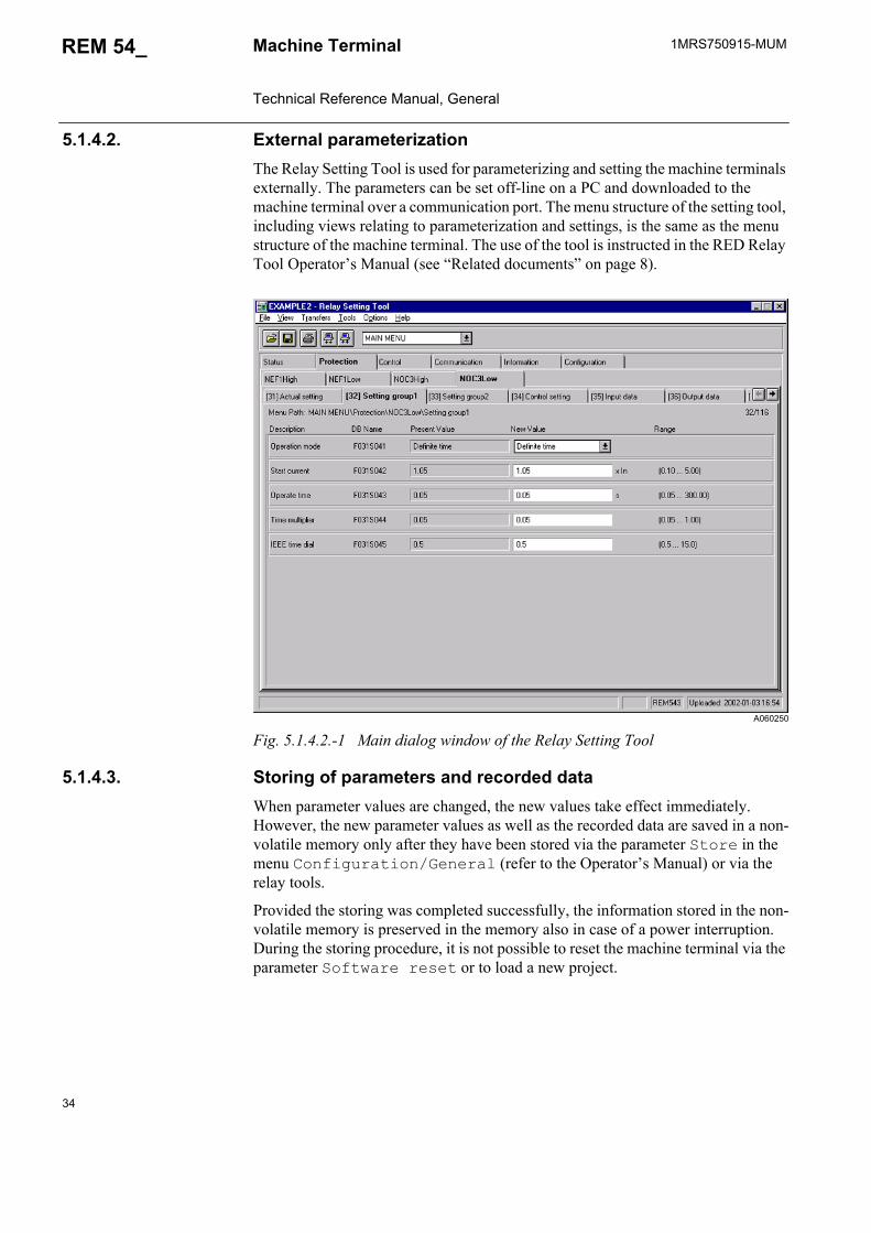
5.1.4.2. External parameterizationThe Relay Setting Tool is used for parameterizing and setting the machine terminals externally. The parameters can be set off-line on a PC and downloaded to the machine terminal over a communication port. The menu structure of the setting tool, including views relating to parameterization and settings, is the same as the menu structure of the machine terminal. The use of the tool is instructed in the RED Relay Tool Operator’s Manual (see “Related documents” on page 8).
A060250
Fig. 5.1.4.2.-1 Main dialog window of the Relay Setting Tool
5.1.4.3. Storing of parameters and recorded dataWhen parameter values are changed, the new values take effect immediately. However, the new parameter values as well as the recorded data are saved in a non-volatile memory only after they have been stored via the parameter Store in the menu Configuration/General (refer to the Operator’s Manual) or via the relay tools.
Provided the storing was completed successfully, the information stored in the non-volatile memory is preserved in the memory also in case of a power interruption. During the storing procedure, it is not possible to reset the machine terminal via the parameter Software reset or to load a new project.
1MRS750915-MUM REM 54_
35
Machine Terminal Technical Reference Manual, General
5.1.5. Auxiliary voltageFor its operation, the machine terminal, including the external display module, requires a secured auxiliary voltage supply. The machine terminal’s internal power supply module forms the voltages required by the machine terminal electronics. The power supply module is a galvanically isolated DC/DC converter. A green protection LED indicator on the front panel is lit when the power supply module is in operation.
The machine terminal is provided with a 48-hour capacitor back-up protection1 that enables the internal clock to keep time in case of an auxiliary power failure.
5.1.5.1. Power supply versionsThe power supply module PS1/_ is available for REM 54_. The module is available in two versions with identical output voltages but different input voltages.
When REM 54_ is delivered with a fixed display module, the input voltage range of the power supply module is marked on the front panel of the machine terminal. When the machine terminal is provided with an external display module, the input voltage of the display module is marked on the front panel of the module and the input voltage of the main unit is marked on the side of the unit.
The external display module is only available together with a main unit equipped with the PS1/240 power supply module.1
The power supply version is specified by the first letter in the order number of REM 54_ (refer to section “Ordering Information” on page 91). The voltage range of the digital inputs is tied to the selected power supply. If a power supply version with the higher rated input voltage is selected, the machine terminals will be delivered with digital inputs that also have the higher rated input voltage.
When the values for the measuring devices (refer to section “Technical data of the measuring devices” on page 41) or communication parameters (refer to section “Serial communication” on page 66) are changed via the HMI or the Relay Setting Tool, the new values take effect only after they have been stored via the parameter Store and the machine terminal has been reset via the parameter Software reset in the menu Configuration/General or by using the relay command buttons Store and Reset in the Relay Download Tool.
The main unit and the external display module must each be provided with separate power supply from a common source.
1. This function is only supported in Release 2.0 or later, refer to section “Revision identification” on page 93.
36
1MRS750915-MUMMachine Terminal Technical Reference Manual, General
REM 54_
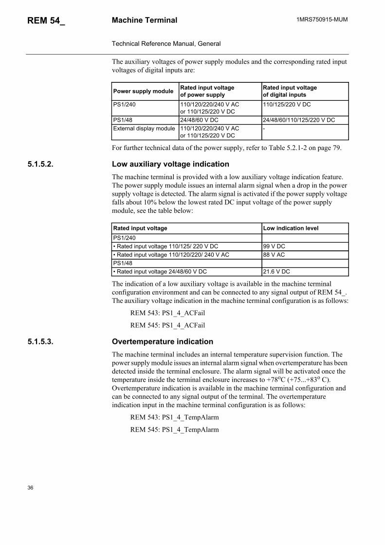
The auxiliary voltages of power supply modules and the corresponding rated input voltages of digital inputs are:
For further technical data of the power supply, refer to Table 5.2.1-2 on page 79.
5.1.5.2. Low auxiliary voltage indicationThe machine terminal is provided with a low auxiliary voltage indication feature. The power supply module issues an internal alarm signal when a drop in the power supply voltage is detected. The alarm signal is activated if the power supply voltage falls about 10% below the lowest rated DC input voltage of the power supply module, see the table below:
The indication of a low auxiliary voltage is available in the machine terminal configuration environment and can be connected to any signal output of REM 54_. The auxiliary voltage indication in the machine terminal configuration is as follows:
REM 543: PS1_4_ACFail
REM 545: PS1_4_ACFail
5.1.5.3. Overtemperature indicationThe machine terminal includes an internal temperature supervision function. The power supply module issues an internal alarm signal when overtemperature has been detected inside the terminal enclosure. The alarm signal will be activated once the temperature inside the terminal enclosure increases to +78oC (+75...+83o C). Overtemperature indication is available in the machine terminal configuration and can be connected to any signal output of the terminal. The overtemperature indication input in the machine terminal configuration is as follows:
REM 543: PS1_4_TempAlarm
REM 545: PS1_4_TempAlarm
Power supply module Rated input voltage of power supply
Rated input voltage of digital inputs
PS1/240 110/120/220/240 V AC or 110/125/220 V DC
110/125/220 V DC
PS1/48 24/48/60 V DC 24/48/60/110/125/220 V DCExternal display module 110/120/220/240 V AC
or 110/125/220 V DC-
Rated input voltage Low indication levelPS1/240• Rated input voltage 110/125/ 220 V DC 99 V DC• Rated input voltage 110/120/220/ 240 V AC 88 V ACPS1/48 • Rated input voltage 24/48/60 V DC 21.6 V DC
1MRS750915-MUM REM 54_
37
Machine Terminal Technical Reference Manual, General
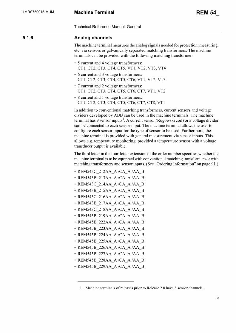
5.1.6. Analog channelsThe machine terminal measures the analog signals needed for protection, measuring, etc. via sensors or galvanically separated matching transformers. The machine terminals can be provided with the following matching transformers:
• 5 current and 4 voltage transformers: CT1, CT2, CT3, CT4, CT5, VT1, VT2, VT3, VT4
• 6 current and 3 voltage transformers: CT1, CT2, CT3, CT4, CT5, CT6, VT1, VT2, VT3
• 7 current and 2 voltage transformers: CT1, CT2, CT3, CT4, CT5, CT6, CT7, VT1, VT2
• 8 current and 1 voltage transformers: CT1, CT2, CT3, CT4, CT5, CT6, CT7, CT8, VT1
In addition to conventional matching transformers, current sensors and voltage dividers developed by ABB can be used in the machine terminals. The machine terminal has 9 sensor inputs1. A current sensor (Rogowski coil) or a voltage divider can be connected to each sensor input. The machine terminal allows the user to configure each sensor input for the type of sensor to be used. Furthermore, the machine terminal is provided with general measurement via sensor inputs. This allows e.g. temperature monitoring, provided a temperature sensor with a voltage transducer output is available.
The third letter in the four-letter extension of the order number specifies whether the machine terminal is to be equipped with conventional matching transformers or with matching transformers and sensor inputs. (See “Ordering Information” on page 91.).
• REM543C_212AA_A /CA_A /AA_B• REM543B_213AA_A /CA_A /AA_B• REM543C_214AA_A /CA_A /AA_B• REM543B_215AA_A /CA_A /AA_B• REM543C_216AA_A /CA_A /AA_B• REM543B_217AA_A /CA_A /AA_B• REM543C_218AA_A /CA_A /AA_B• REM543B_219AA_A /CA_A /AA_B• REM545B_222AA_A /CA_A /AA_B• REM545B_223AA_A /CA_A /AA_B• REM545B_224AA_A /CA_A /AA_B• REM545B_225AA_A /CA_A /AA_B• REM545B_226AA_A /CA_A /AA_B• REM545B_227AA_A /CA_A /AA_B• REM545B_228AA_A /CA_A /AA_B• REM545B_229AA_A /CA_A /AA_B
1. Machine terminals of releases prior to Release 2.0 have 8 sensor channels.
38
1MRS750915-MUMMachine Terminal Technical Reference Manual, General
REM 54_
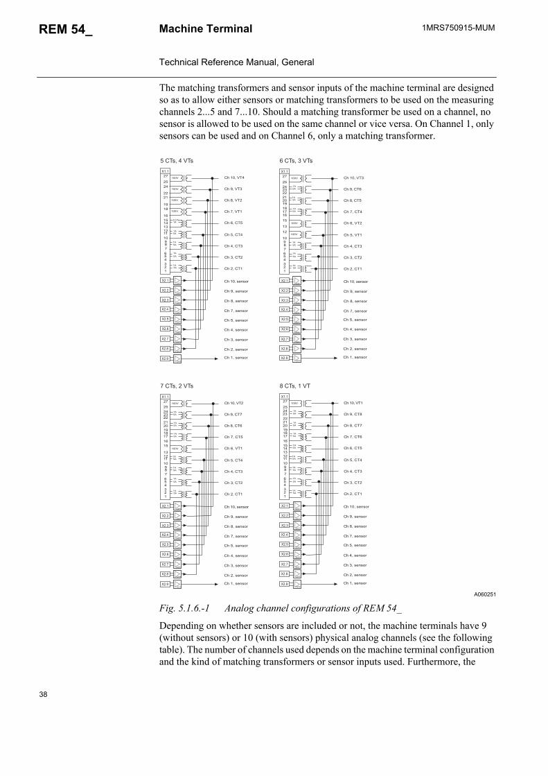
The matching transformers and sensor inputs of the machine terminal are designed so as to allow either sensors or matching transformers to be used on the measuring channels 2...5 and 7...10. Should a matching transformer be used on a channel, no sensor is allowed to be used on the same channel or vice versa. On Channel 1, only sensors can be used and on Channel 6, only a matching transformer.
A060251
Fig. 5.1.6.-1 Analog channel configurations of REM 54_
Depending on whether sensors are included or not, the machine terminals have 9 (without sensors) or 10 (with sensors) physical analog channels (see the following table). The number of channels used depends on the machine terminal configuration and the kind of matching transformers or sensor inputs used. Furthermore, the
��'�
����
��'�
��'�
��'�
&�(�
���'
�����
)��'*��
���+
�+�)��
����
��
�'�*�
'���
'���
��'���
����
��'�
����
��'�
��'�
��'�
&�(�
���'�*�����
)��'*��
���+
�+�)��
����
��
�'�*
'���
'���
'���
��
'���
�
��'�
�(�����
����
����
����
����
��'�
��'�
��'�
&�(�
���'�*�����
)��'*��
���+
�+�)
����
��
�'�*
����
��'�
��'�
��'�
&�(�
�)����
�'
�
��
)��'*��
���+
�����+
���
��
�'�*
'���
'���
����
����
��'�
&�(�
&�(�
&�(
&�(*
&�('
&�(�
&�(�
&�()����
����
����
����
����
����
����
����
&�(+����
&�(�
&�(�
&�(
&�(*
&�('
&�(�
&�(�
&�()����
����
����
����
����
����
����
����
&�(+����
&�(�
&�(�
&�(
&�(*
&�('
&�(�
&�(�
&�()����
����
����
����
����
����
����
����
&�(+����
&�(�
&�(�
&�(
&�(*
&�('
&�(�
&�(�
&�(+����
����
����
����
����
����
����
����
&�()
�!��,��-�
�!��,��-'
�!�),��-�
�!�+,��-�
�!���,��-�
�!��,��-�
�!�,��-�
�!�*,��-
�!�',��-*
�!�+,��./��0
�!���,��./��0
�!�),��./��0
�!��,��./��0
�!�*,��./��0
�!�,��./��0
�!��,��./��0
�!��,��./��0
�!�',��./��0
���-�,����-�
�!��,��-'
�!��,��-�
�!�),��-�
�!�+,��-)
�!���,��-�
�!��,��-�
�!�,��-�
�!�*,��-
�!�',��-*
�!�+,��./��0
�!���,��./��0
�!�),��./��0
�!��,��./��0
�!�*,��./��0
�!�,��./��0
�!��,��./��0
�!��,��./��0
�!�',��./��0
)��-�,����-
�!��,��-'
�!��,��-�
�!�),��-�
�!�+,��-
�!���,��-*
�!��,��-�
�!�,��-�
�!�*,��-
�!�',��-*
�!�+,��./��0
�!���,��./��0
�!�),��./��0
�!��,��./��0
�!�*,��./��0
�!�,��./��0
�!��,��./��0
�!��,��./��0
�!�',��./��0
'��-�,�*��-�
�!��,��-�
�!��,��-*
�!�),��-'
�!�+,��-�
�!���,��-
�!��,��-�
�!�,��-�
�!�*,��-
�!�',��-�
�!�+,��./��0
�!���,��./��0
�!�),��./��0
�!��,��./��0
�!�*,��./��0
�!�,��./��0
�!��,��./��0
�!��,��./��0
�!�',��./��0
���-�,���-�

1MRS750915-MUM REM 54_
39
Machine Terminal Technical Reference Manual, General
machine terminal includes virtual analog channels (refer to section “Calculated analog channels” on page 43) for calculating the neutral current and residual voltage from phase currents and voltages.
Each analog channel is separately configured with the Relay Configuration Tool. Both the measuring unit for each analog channel and the type of signal to be measured are to be configured.
The letters b and c after the signal type are used to distinguish between signals of the same type.
Table 5.1.6-1 Physical analog channels of the machine terminals
Measuring units
Ch No.
Current Transformer (CT)
Voltage Transformer (VT)
Rogowski coil/-sensor (RS)
Voltage divider (VD)
General measure-ment
Signal type (selectable alternatives)
1
RS 1...10 VD 1...10 Gen. meas. 1...3
Not in use, IL1, IL2, IL3, IL1b, IL2b, IL3b, U1, U2, U3, U1b, U2b, U3b, U1c, GE1, GE2, GE3
2 Current Transformer CT1 (In= 1 A/5 A)
RS 1...10 VD 1...10 Gen. meas. 1...3
Not in use, IL1, IL2, IL3, IL1b, IL2b, IL3b, I0, I0b, U1, U2, U3, U1b, U2b, U3b, U1c, GE1, GE2, GE3
3 Current Transformer CT2 (In= 1 A/5 A)
4Current Transformer CT3 (In= 1 A/5 A)
5
Current Transformer CT4 (In= 1 A/5 A)
Voltage Transformer VT1 (Un=100V/110V/115V/120V)
RS 1...10 VD 1...10 Gen. meas. 1...3
Not in use, IL1, IL2, IL3, IL1b, IL2b, IL3b, I0, I0b, U12, U23, U31, U12b, U23b, U31b, U12c, U1, U2, U3, U1b, U2b, U3b, U1c, U0, U0b, GE1, GE2, GE3
6
Current Transformer CT5 (In= 0.2 A/1 A)
Voltage Transformer VT1 or VT2 (Un=100V/110V/115V/120V)
Not in use, IL1, IL2, IL3, IL1b, IL2b, IL3b, I0, I0b, U12, U23, U31, U12b, U23b, U31b, U12c, U1, U2, U3, U1b, U2b, U3b, U1c, U0, U0b
7Current Transformer CT4, CT5 or CT6 (In= 1 A/5 A)
Voltage Transformer VT1 (Un=100V/110V/115V/120V)
RS 1...10 VD 1...10 Gen. meas. 1...3
Not in use, IL1, IL2, IL3, IL1b, IL2b, IL3b, I0, I0b, U12, U23, U31, U12b, U23b, U31b, U12c, U1, U2, U3, U1b, U2b, U3b, U1c, U0, U0b, GE1, GE2, GE3
8Current Transformer CT5, CT6 or CT7(In= 1 A/5 A)
Voltage Transformer VT2 (Un=100V/110V/115V/120V)
9Current Transformer CT6, CT7 or CT8(In= 1 A/5 A)
Voltage Transformer VT3 (Un=100V/110V/115V/120V)
10
Voltage Transformer VT4 (Un=100V/110V/115V/120V)
RS 1...10 VD 1...10 Gen. meas. 1...3
Not in use, IL1, IL2, IL3, IL1b, IL2b, IL3b, U12, U23, U31, U12b, U23b, U31b, U12c, U1, U2, U3, U1b, U2b, U3b, U1c, U0, U0b, GE1, GE2, GE3
40
1MRS750915-MUMMachine Terminal Technical Reference Manual, General
REM 54_
5.1.6.1. Scaling the rated values of the protected unit for analog channelA separate scaling factor can be set for each analog channel. The factors enable differences between the ratings of the protected unit (generator, transformer, motor, etc.) and those of the measuring device (CTs, VTs, etc.) The setting value 1.00 means that the rated value of the protected unit is exactly the same as that of the measuring device.
When scaling factors are used, it should be noted that they affect the operation accuracy of the terminal. The accuracies stated in the function block manuals on CD-ROM Technical Descriptions of Functions only apply with the default values of the scaling factors. For example, a high factor affects the operation of sensitive protection functions such as the directional earth-fault protection.
The scaling factor is calculated channel by channel as follows:
Scaling factor = Inmd / Inp, where
Example:
The scaling factors for the analog channels can be set via the HMI of the machine terminal or with the Relay Setting Tool. The HMI path for the scaling factors is: Main Menu/Configuration/Protected Unit/Ch 1: scaling, Ch 2: scaling...
Inmd Rated primary current of the measuring device (A)Inp Rated primary current of the protected unit connected to the channel
Rated primary current of current trafo = 500 A: Inmd = 500 ARated current of the protected unit = 250 A: Inp = 250 AScaling factor for current channels: 500 A / 250 A = 2.00
The scaling factor is not used for general measurement signals connected to the analog channel.
1MRS750915-MUM REM 54_
41
Machine Terminal Technical Reference Manual, General
5.1.6.2. Technical data of the measuring devicesWhen the machine terminal is configured, the technical data of the measuring devices is set in separate dialog boxes in the Relay Configuration Tool. The set values will affect the measurements carried out by the machine terminal.
For storing the values listed below, refer to section “Storing of parameters and recorded data” on page 34.Values to be set for a current transformer are:
• rated primary current (0...6000 A) of the primary current transformer• rated secondary current (5 A, 2 A, 1 A, 0.2 A) of the primary current transformer• rated current (5 A, 1 A, 0.2 A) of the current measuring input (= rated current of
the matching transformer of the machine terminal)• amplitude correction factor (0.9000...1.1000) of the primary current transformer
at rated current• correction parameter for the phase displacement error of the primary current
transformer at rated current (-5.00°...0.00°)• amplitude correction factor of the primary current transformer at a signal level of
1% of the rated current (0.9000...1.1000)• correction parameter for the phase displacement error of the primary current
transformer at a signal level of 1% of the rated current (-10.00°...0.00°)
Values to be set for a voltage transformer are:
• rated voltage of voltage input (same as the secondary rated voltage of the primary voltage transformer connected to the voltage input, 100 V, 110 V, 115 V, 120 V)
• rated voltage of primary voltage transformer (0...440 kV)• amplitude correction factor of the primary voltage transformer voltage at rated
voltage (0.9000...1.1000)• correction parameter for the primary transformer phase displacement error at
rated voltage (-2.00°... 2.00°)
Values to be set for a current sensor (Rogowski coil) are:
• secondary rated voltage of the current sensor used at the preset primary rated current (0...300 mV)
• primary rated current of the current sensor used (0...6000 A)• amplitude correction factor of the current sensor used at rated current
(0.9000...1.1000)• correction parameter for the phase displacement error of the current sensor
(-1.0000°...1.0000°)1
1. Only included in Release 2.0 or later, refer to section “Revision identification” on page 93. Note that this parameter can only be set via the HMI or the Relay Setting Tool.
42
1MRS750915-MUMMachine Terminal Technical Reference Manual, General
REM 54_
Values to be set for a voltage divider are:
• division ratio of the voltage divider primary and secondary voltage (0...20000)• rated value of primary phase-to-phase voltage (0...440 kV)• amplitude correction factor of the voltage divider (0.9000...1.1000)• correction parameter for the phase displacement error of the voltage divider
(-1.0000°...1.0000°)1
Values to be set for general measurement:2
• amplitude correction factor of general measurement (-10000.00000...10000.00000)
• correction parameter for the offset correction of general measurement (-10000.00000...10000.00000)
The measurement values stated by the manufacturer of the measuring device are used for calculating the correction parameters and factors according to the following formulas:
Current transformers
Voltage transformers
Rogowski coil
Voltage divider
1. Only included in Release 2.0 or later, refer to section “Revision identification” on page 93. Note that this parameter can only be set via the HMI or the Relay Setting Tool.
2. Only included in Release 2.0 or later, refer to section “Revision identification” on page 93.
Amplitude error at current In(e = error in per cent)
Amplitude correction factor 1= 1 / (1+ e/100)
Amplitude error at current 0.01 x In(e = error in per cent)
Amplitude correction factor 2= 1 / (1+ e/100)
Phase displacement error at current In(e = error in degrees)
Phase displacement error 1 = - e
Phase displacement error at current 0.01 x In(e = error in degrees)
Phase displacement error 2 = - e
Amplitude error at voltage Un(e = error in per cent)
Amplitude correction factor = 1 / (1+ e/100)
Phase displacement error at voltage Un(e = error in degrees)
Phase displacement error = - e
Amplitude error at the whole measuring range(e = error in per cent)
Amplitude correction factor = 1 / (1+ e/100)
Phase displacement error at the whole measuring range (e = error in degrees)
Phase displacement error = - e
Amplitude error at the whole measuring range(e = error in per cent)
Amplitude correction factor = 1 / (1+ e/100)
Phase displacement error at the whole measuring range (e = error in degrees)
Phase displacement error = - e
1MRS750915-MUM REM 54_
43
Machine Terminal Technical Reference Manual, General
5.1.6.3. Calculated analog channelsThe machine terminal includes virtual channels to obtain neutral current and residual voltage when sensors are used. Current sensors and voltage dividers are connected to the machine terminal via coaxial cables and therefore a residual connection of phase currents or an open-delta connection of phase voltages cannot be made. Both the amplitude and the phase angle are calculated for the virtual channels.
Though primarily meant to be used with sensors, the calculated analog channels can also be used with conventional current and voltage transformers.
The neutral current I0 is numerically derived from the three phase currents:. Minus in front of the parenthesis means that the default
direction of neutral current is assumed to be from the line to the busbar, while the normal power flow is from the busbar to the line.
The residual voltage U0 is numerically derived from the three phase voltages:. U0S is used instead of the open-delta connection when
voltage dividers are used to measure phase-to-earth voltages.
If only one virtual channel is used, the channel will be numbered as 11. If both calculations are used, the I0S channel will be given the number 11 and the U0S channel the number 12.
5.1.7. Digital inputsThe REM 543 and REM 545 machine terminals differ from each other regarding the number of digital inputs available.
The digital inputs of the REM 54_ machine terminals are voltage-controlled and optically isolated. For technical data of the digital inputs, refer to Table 5.2.1-3 on page 79.
The parameters for input filtering, input inversion and pulse counters (see sections below) can be set in the Configuration menu under each I/O card (e.g. Configuration/BIO1/Input filtering).
The events and parameters of I/O cards are included in the event and parameter lists on the CD-ROM Technical Descriptions of Functions.
When sensitive earth-fault protection is needed, core balance transformers are not recommended to be replaced with the numerically derived sum of phase currents. Normally, an earth-fault setting below 10% of the rated value requires the use of a core balance transformer.
I os I L1 I L2 I L3+ + –=
U os U 1 U 2 U 3+ + 3=

44
1MRS750915-MUMMachine Terminal Technical Reference Manual, General
REM 54_
Table 5.1.7-1 Digital inputs available for REM 54_
REM 543 REM 545Inputs PS1_4_BI1 a
a. These digital inputs can be programmed as either digital inputs or pulse counters, refer to section “Pulse counters” on page 46.
PS1_4_BI1 a
PS1_4_BI2 a PS1_4_BI2 a
PS1_4_BI3 a PS1_4_BI3 a
BIO1_5_BI1 BIO1_5_BI1 BIO1_5_BI2 BIO1_5_BI2 BIO1_5_BI3 BIO1_5_BI3 BIO1_5_BI4 BIO1_5_BI4BIO1_5_BI5 BIO1_5_BI5 BIO1_5_BI6 BIO1_5_BI6 BIO1_5_BI7 BIO1_5_BI7 BIO1_5_BI8 BIO1_5_BI8
BIO1_5_BI9 1) BIO1_5_BI9 a
BIO1_5_BI10 a BIO1_5_BI10 a
BIO1_5_BI11 a BIO1_5_BI11 a
BIO1_5_BI12 a BIO1_5_BI12 a
BIO2_7_BI1 BIO2_7_BI2BIO2_7_BI3BIO2_7_BI4 BIO2_7_BI5BIO2_7_BI6 BIO2_7_BI7 BIO2_7_BI8
BIO2_7_BI9 1)
BIO2_7_BI10 1)
Digital inputs / total
15 25
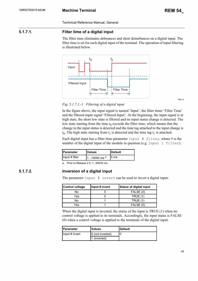
1MRS750915-MUM REM 54_
45
Machine Terminal Technical Reference Manual, General
5.1.7.1. Filter time of a digital inputThe filter time eliminates debounces and short disturbances on a digital input. The filter time is set for each digital input of the terminal. The operation of input filtering is illustrated below.
dipo_b
Fig. 5.1.7.1.-1 Filtering of a digital input
In the figure above, the input signal is named ‘Input’, the filter timer ‘Filter Time’ and the filtered input signal ‘Filtered Input’. At the beginning, the input signal is at high state, the short low state is filtered and no input status change is detected. The low state starting from the time t0 exceeds the filter time, which means that the change in the input status is detected and the time tag attached to the input change is t0. The high state starting from t1 is detected and the time tag t1 is attached.
Each digital input has a filter time parameter Input # filter, where # is the number of the digital input of the module in question (e.g. Input 1 filter).
5.1.7.2. Inversion of a digital inputThe parameter Input # invert can be used to invert a digital input:
When the digital input is inverted, the status of the input is TRUE (1) when no control voltage is applied to its terminals. Accordingly, the input status is FALSE (0) when a control voltage is applied to the terminals of the digital input.
Parameter Values DefaultInput # filter 1...15000 ms a
a. Prior to Release 2.5: 1...65535 ms.
5 ms
�# ��
$���� %�
$����& ���!�
���!�
$���� %�
Control voltage Input # invert Status of digital inputNo 0 FALSE (0)Yes 0 TRUE (1)No 1 TRUE (1)Yes 1 FALSE (0)
Parameter Values DefaultInput # invert 0 (not inverted) 0
1 (inverted)
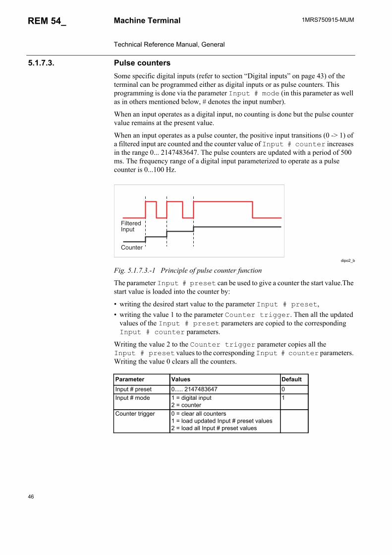
46
1MRS750915-MUMMachine Terminal Technical Reference Manual, General
REM 54_
5.1.7.3. Pulse countersSome specific digital inputs (refer to section “Digital inputs” on page 43) of the terminal can be programmed either as digital inputs or as pulse counters. This programming is done via the parameter Input # mode (in this parameter as well as in others mentioned below, # denotes the input number).
When an input operates as a digital input, no counting is done but the pulse counter value remains at the present value.
When an input operates as a pulse counter, the positive input transitions (0 -> 1) of a filtered input are counted and the counter value of Input # counter increases in the range 0... 2147483647. The pulse counters are updated with a period of 500 ms. The frequency range of a digital input parameterized to operate as a pulse counter is 0...100 Hz.
dipo2_b
Fig. 5.1.7.3.-1 Principle of pulse counter function
The parameter Input # preset can be used to give a counter the start value.The start value is loaded into the counter by:
• writing the desired start value to the parameter Input # preset,• writing the value 1 to the parameter Counter trigger. Then all the updated
values of the Input # preset parameters are copied to the corresponding Input # counter parameters.
Writing the value 2 to the Counter trigger parameter copies all the Input # preset values to the corresponding Input # counter parameters. Writing the value 0 clears all the counters.
Parameter Values DefaultInput # preset 0..... 2147483647 0Input # mode 1 = digital input
2 = counter1
Counter trigger 0 = clear all counters1 = load updated Input # preset values2 = load all Input # preset values
$����&���!�
��!���
1MRS750915-MUM REM 54_
47
Machine Terminal Technical Reference Manual, General
5.1.7.4. Oscillation suppressionOscillation suppression is used to reduce the load from the system when, for some unrecognized reason, a digital input starts oscillating. A digital input is regarded as oscillating if the number of valid status changes (= number of events after filtering) during 1 second is greater than the set value Input osc. level (Oscillation level). During oscillation, the digital input is blocked (status is invalid) and an event is generated. The state of the input will not change when it is blocked, i.e. its state depends on the condition before blocking.
The digital input is regarded as non-oscillating if the number of valid status changes during 1 second is less than the set value of Input osc. level minus the set value of Input osc. hyst. (Oscillation hysteresis). Note that the oscillation hysteresis must be set lower than the oscillation level to enable the input to be restored from oscillation. When the input returns to a non-oscillating state, the digital input is deblocked (status is valid) and an event is generated.
5.1.7.5. Attributes of a digital input for machine terminal configurationThe validity of the digital input (invalidity), the status of the input (value), the time tag for the status change (time) and the counter value of the input can be issued for each digital input by the attributes BI#IV, BI#, BI#Time and BI#Count, where # denotes the number of the input. These attributes are available in the machine terminal configuration and can be used for different purposes.
The example below shows how the attributes of the digital input 1 (PS1_4_BI1 on PS1 module) of the machine terminal are named for the configuration:
PS1_4_BI1IV; digital input invalidity
PS1_4_BI1; digital input value
PS1_4_BI1Time; time tag
PS1_4_BT1Count; counter value
Invalidity (BI#IV)
When a digital input oscillates, the invalidity attribute IV changes to TRUE (1) and the input is blocked. The digital input is regarded as being blocked and oscillating if the number of status changes per second exceeds the set Input osc. level value (events/s).
When a digital input does not oscillate, the invalidity attribute IV changes to FALSE (0) and the input becomes operative. The digital input is regarded as being operative and non-oscillating if the number of status changes per second is less than the set Input osc. level value minus the set Input osc. hyst. value (events/s).
Parameter Values DefaultInput osc. level 2...50 events/s 50 events/sInput osc. hyst. 2...50 events/s 10 events/s
Unlike most parameters for digital I/O cards, the parameters Input osc. level and Input osc. hyst. can be found in the menu Configuration/General.
48
1MRS750915-MUMMachine Terminal Technical Reference Manual, General
REM 54_
Value (BI#)
Depending on the status of the digital input, the digital input value is TRUE (1) or FALSE (0). The BI# value changes on the rising or falling edge of the input. To prevent undesired status changes of the digital input due to switch debouncing, etc., the change of the attribute value is delayed by the filter time.
The counter attribute of a digital input is not updated when the input is programmed as a normal digital input.
Time (BI#Time)
Each change (rising or falling edge) detected in the status of a digital input is time-tagged at an accuracy of ±1 ms. The time tag represents the moment (time) of the latest input change of the value attribute. The time is not recorded until the filtering time of the status change has elapsed, which means that the filtering time does not affect the time tag value.
Count (BI#Count)
The count attribute indicates the number of positive input transitions of a filtered input.
5.1.8. Digital outputsThe outputs of the machine terminal are categorized as follows:
The events and parameters of I/O cards are included in the event and parameter lists on the CD-ROM Technical Descriptions of Functions (see “Related documents” on page 8).
For information about terminal connections for the outputs, refer to terminal diagrams (beginning on page 84), where all the outputs are included with relay connector terminals.
For technical data of the outputs, see Table 5.2.1-6 on page 80.
HSPO High-speed power output, double-pole contact, preferred for tripping purposes and for circuit breaker and disconnector control
PO Power output, either single-pole or double-pole contact, preferred for circuit breaker and disconnector control
SO Signal output, either NO (Normally Open) or NO/NC (Normally Open/Normally Closed) contact
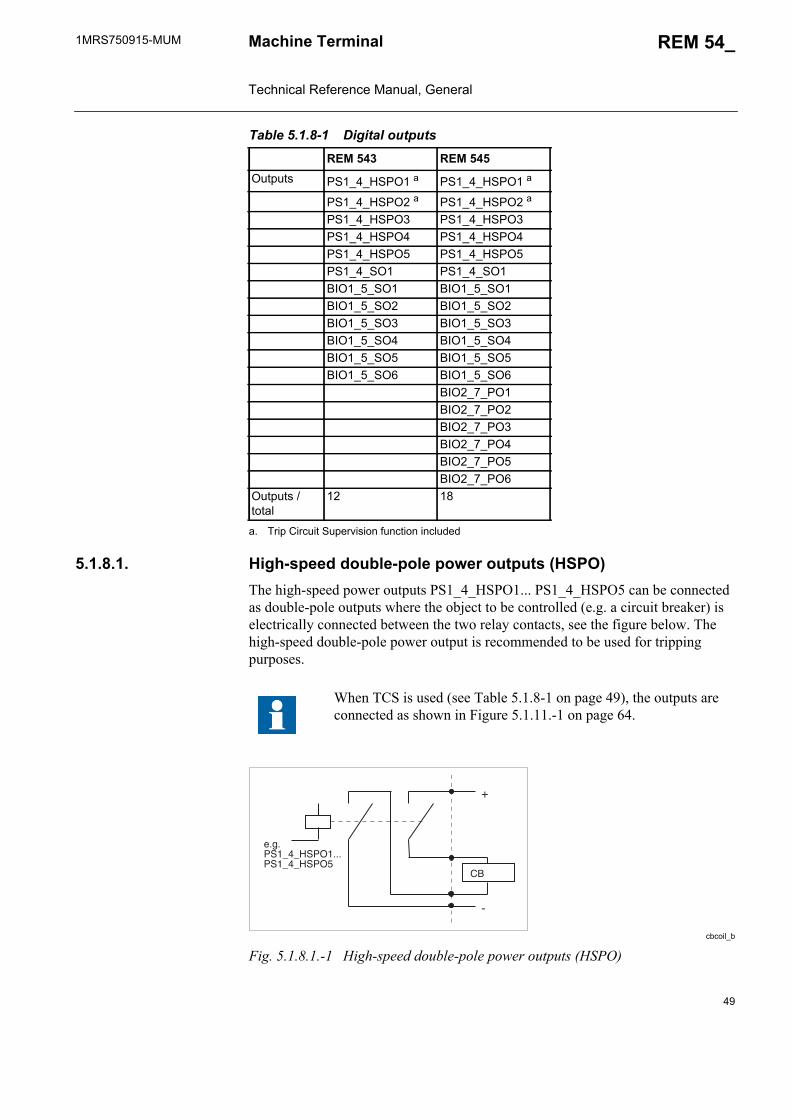
1MRS750915-MUM REM 54_
49
Machine Terminal Technical Reference Manual, General
5.1.8.1. High-speed double-pole power outputs (HSPO)The high-speed power outputs PS1_4_HSPO1... PS1_4_HSPO5 can be connected as double-pole outputs where the object to be controlled (e.g. a circuit breaker) is electrically connected between the two relay contacts, see the figure below. The high-speed double-pole power output is recommended to be used for tripping purposes.
cbcoil_b
Fig. 5.1.8.1.-1 High-speed double-pole power outputs (HSPO)
Table 5.1.8-1 Digital outputs
REM 543 REM 545Outputs PS1_4_HSPO1 a
a. Trip Circuit Supervision function included
PS1_4_HSPO1 a
PS1_4_HSPO2 a PS1_4_HSPO2 a
PS1_4_HSPO3 PS1_4_HSPO3 PS1_4_HSPO4 PS1_4_HSPO4PS1_4_HSPO5 PS1_4_HSPO5PS1_4_SO1 PS1_4_SO1 BIO1_5_SO1 BIO1_5_SO1BIO1_5_SO2 BIO1_5_SO2BIO1_5_SO3 BIO1_5_SO3BIO1_5_SO4 BIO1_5_SO4BIO1_5_SO5 BIO1_5_SO5BIO1_5_SO6 BIO1_5_SO6
BIO2_7_PO1BIO2_7_PO2BIO2_7_PO3BIO2_7_PO4BIO2_7_PO5BIO2_7_PO6
Outputs / total
12 18
When TCS is used (see Table 5.1.8-1 on page 49), the outputs are connected as shown in Figure 5.1.11.-1 on page 64.
'
�
��
(�()*����+*)��((()*����+*)��

50
1MRS750915-MUMMachine Terminal Technical Reference Manual, General
REM 54_
The high-speed power outputs PS1_4_HSPO1... PS1_4_HSPO5 can also be connected as single-pole power outputs where the object to be controlled (e.g. a circuit breaker) is electrically connected in series with the two relay contacts, see the figure below.
doubpole_b
Fig. 5.1.8.1.-2 High-speed single-pole power outputs (HSPO)
5.1.8.2. Single-pole power outputs (PO)The single-pole power outputs BIO2_7_PO1 and BIO2_7_PO2 are outputs where the object to be controlled is connected in series with two heavy-duty output relay contacts, see the figure below. These outputs can be used for tripping purposes and for circuit breaker and disconnector control.
PO1conn_b
Fig. 5.1.8.2.-1 Single-pole power outputs (PO)
Double-pole power outputs (PO)The double-pole power outputs BIO2_7_PO3... BIO2_7_PO6 are outputs where the object to be controlled (e.g. a circuit breaker) is electrically connected between the two relay contacts, see the figure below. These outputs can be used for tripping purposes and for circuit breaker and disconnector control.
�
1
��
(�()*����+*)��((()*����+*)��
'
�
��
(�(���,�-�)��.���,�-�)�,
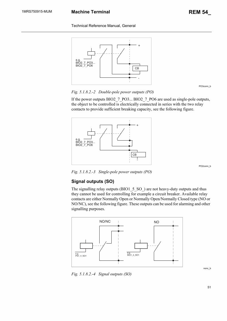
1MRS750915-MUM REM 54_
51
Machine Terminal Technical Reference Manual, General
PO3conn_b
Fig. 5.1.8.2.-2 Double-pole power outputs (PO)
If the power outputs BIO2_7_PO3... BIO2_7_PO6 are used as single-pole outputs, the object to be controlled is electrically connected in series with the two relay contacts to provide sufficient breaking capacity, see the following figure.
PO2conn_b
Fig. 5.1.8.2.-3 Single-pole power outputs (PO)
Signal outputs (SO)The signalling relay outputs (BIO1_5_SO_) are not heavy-duty outputs and thus they cannot be used for controlling for example a circuit breaker. Available relay contacts are either Normally Open or Normally Open/Normally Closed type (NO or NO/NC), see the following figure. These outputs can be used for alarming and other signalling purposes.
nonc_b
Fig. 5.1.8.2.-4 Signal outputs (SO)
'
�
��
(�(���,�-�)�/(((���,�-�)�0
'
�
��
(�(���,�-�)�/(((���,�-�)�0
��"�� ��
(�()*����*��
(�(�������*��
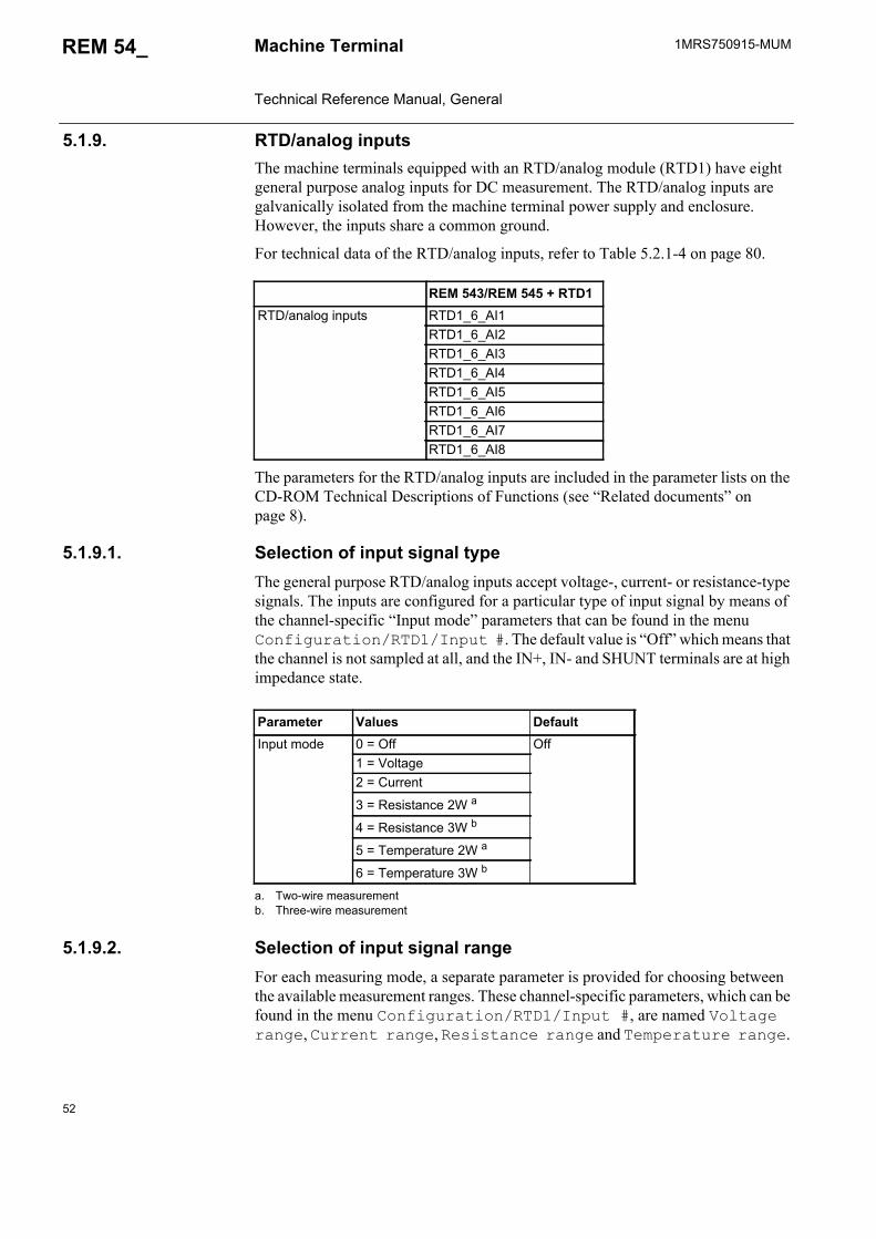
52
1MRS750915-MUMMachine Terminal Technical Reference Manual, General
REM 54_
5.1.9. RTD/analog inputsThe machine terminals equipped with an RTD/analog module (RTD1) have eight general purpose analog inputs for DC measurement. The RTD/analog inputs are galvanically isolated from the machine terminal power supply and enclosure. However, the inputs share a common ground.
For technical data of the RTD/analog inputs, refer to Table 5.2.1-4 on page 80.
The parameters for the RTD/analog inputs are included in the parameter lists on the CD-ROM Technical Descriptions of Functions (see “Related documents” on page 8).
5.1.9.1. Selection of input signal typeThe general purpose RTD/analog inputs accept voltage-, current- or resistance-type signals. The inputs are configured for a particular type of input signal by means of the channel-specific “Input mode” parameters that can be found in the menu Configuration/RTD1/Input #. The default value is “Off” which means that the channel is not sampled at all, and the IN+, IN- and SHUNT terminals are at high impedance state.
5.1.9.2. Selection of input signal rangeFor each measuring mode, a separate parameter is provided for choosing between the available measurement ranges. These channel-specific parameters, which can be found in the menu Configuration/RTD1/Input #, are named Voltage range, Current range, Resistance range and Temperature range.
REM 543/REM 545 + RTD1RTD/analog inputs RTD1_6_AI1
RTD1_6_AI2RTD1_6_AI3RTD1_6_AI4RTD1_6_AI5RTD1_6_AI6RTD1_6_AI7RTD1_6_AI8
Parameter Values DefaultInput mode 0 = Off Off
1 = Voltage2 = Current
3 = Resistance 2W a
a. Two-wire measurement
4 = Resistance 3W b
b. Three-wire measurement
5 = Temperature 2W a
6 = Temperature 3W b
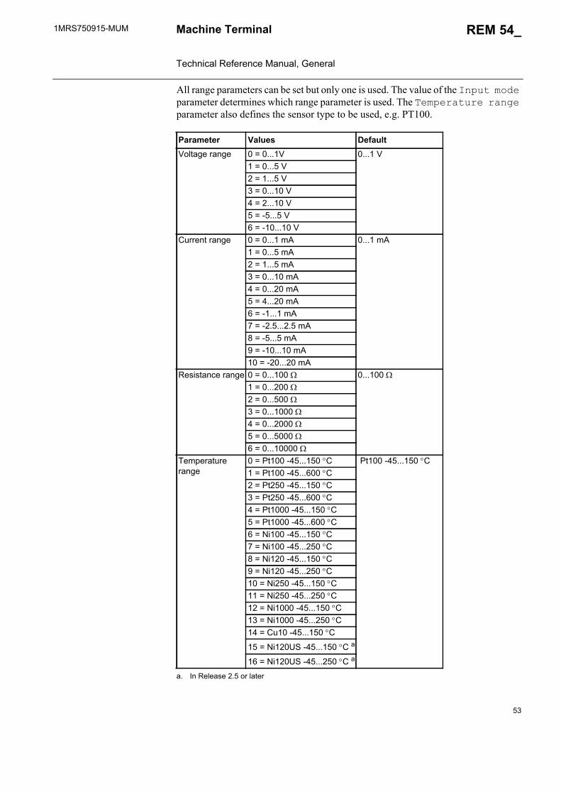
1MRS750915-MUM REM 54_
53
Machine Terminal Technical Reference Manual, General
All range parameters can be set but only one is used. The value of the Input mode parameter determines which range parameter is used. The Temperature range parameter also defines the sensor type to be used, e.g. PT100.
Parameter Values DefaultVoltage range 0 = 0...1V 0...1 V
1 = 0...5 V2 = 1...5 V3 = 0...10 V4 = 2...10 V5 = -5...5 V6 = -10...10 V
Current range 0 = 0...1 mA 0...1 mA1 = 0...5 mA2 = 1...5 mA3 = 0...10 mA4 = 0...20 mA5 = 4...20 mA6 = -1...1 mA7 = -2.5...2.5 mA8 = -5...5 mA9 = -10...10 mA10 = -20...20 mA
Resistance range 0 = 0...100 0...100 1 = 0...200 2 = 0...500 3 = 0...1000 4 = 0...2000 5 = 0...5000 6 = 0...10000
Temperature range
0 = Pt100 -45...150 C Pt100 -45...150 C1 = Pt100 -45...600 C2 = Pt250 -45...150 C3 = Pt250 -45...600 C4 = Pt1000 -45...150 C 5 = Pt1000 -45...600 C 6 = Ni100 -45...150 C7 = Ni100 -45...250 C8 = Ni120 -45...150 C9 = Ni120 -45...250 C 10 = Ni250 -45...150 C11 = Ni250 -45...250 C12 = Ni1000 -45...150 C13 = Ni1000 -45...250 C14 = Cu10 -45...150 C
15 = Ni120US -45...150 C a
a. In Release 2.5 or later
16 = Ni120US -45...250 C a
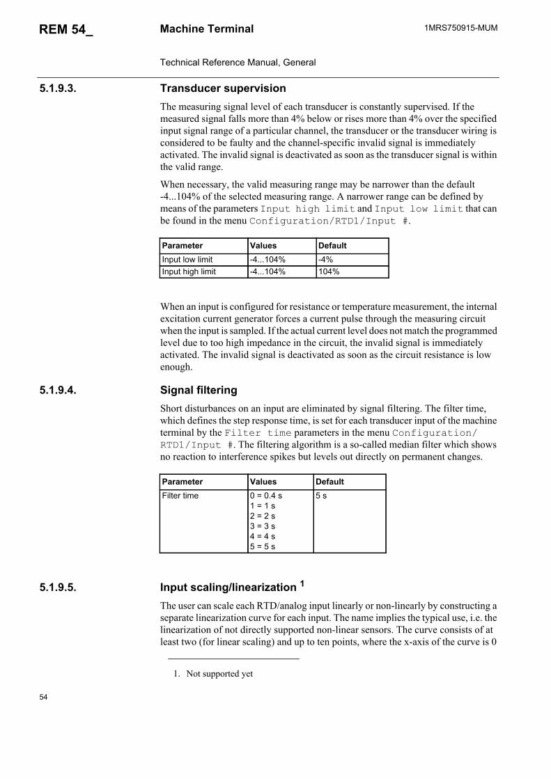
54
1MRS750915-MUMMachine Terminal Technical Reference Manual, General
REM 54_
5.1.9.3. Transducer supervisionThe measuring signal level of each transducer is constantly supervised. If the measured signal falls more than 4% below or rises more than 4% over the specified input signal range of a particular channel, the transducer or the transducer wiring is considered to be faulty and the channel-specific invalid signal is immediately activated. The invalid signal is deactivated as soon as the transducer signal is within the valid range.
When necessary, the valid measuring range may be narrower than the default -4...104% of the selected measuring range. A narrower range can be defined by means of the parameters Input high limit and Input low limit that can be found in the menu Configuration/RTD1/Input #.
When an input is configured for resistance or temperature measurement, the internal excitation current generator forces a current pulse through the measuring circuit when the input is sampled. If the actual current level does not match the programmed level due to too high impedance in the circuit, the invalid signal is immediately activated. The invalid signal is deactivated as soon as the circuit resistance is low enough.
5.1.9.4. Signal filteringShort disturbances on an input are eliminated by signal filtering. The filter time, which defines the step response time, is set for each transducer input of the machine terminal by the Filter time parameters in the menu Configuration/RTD1/Input #. The filtering algorithm is a so-called median filter which shows no reaction to interference spikes but levels out directly on permanent changes.
5.1.9.5. Input scaling/linearization 1
The user can scale each RTD/analog input linearly or non-linearly by constructing a separate linearization curve for each input. The name implies the typical use, i.e. the linearization of not directly supported non-linear sensors. The curve consists of at least two (for linear scaling) and up to ten points, where the x-axis of the curve is 0
Parameter Values DefaultInput low limit -4...104% -4%Input high limit -4...104% 104%
Parameter Values DefaultFilter time 0 = 0.4 s
1 = 1 s2 = 2 s3 = 3 s4 = 4 s5 = 5 s
5 s
1. Not supported yet

1MRS750915-MUM REM 54_
55
Machine Terminal Technical Reference Manual, General
to 1000 per mille of the range selected for the input and the y-axis is the scaled absolute value of the input. The linearization curves can be enabled and disabled with the Linear. curve parameters in the menu Configuration/RTD1/Input #. The curve is constructed and downloaded to the machine terminal by using a special tool in the relay toolbox.
When the linearization curve is enabled, the Input high limit and Input low limit parameters affect the scaled range instead of the range selected by the parameters. The range of the scaled input is defined as the range between the smallest y-axis value and the largest y-axis value.
5.1.9.6. Transducer connectionsThe RTD/analog inputs may be connected to a large variety of different measuring transducer types, both standardized and customer-specified types.
Three connection screws have been reserved for each channel. Further, one connection screw (analog ground) has been reserved per every two channels.
Two earth terminals (see figure below), located to the left of the connectors, are reserved for connecting the protective sheaths of the transducer input cables. The cable sheath is generally earthed in one end of the cable only.
A060252
Fig. 5.1.9.6.-1 Earth terminals
Parameter Values DefaultLinear. curve 0 = Disabled
1 = EnabledDisabled
��*'��)+��������*�'�����)
��*'��)+��������*�'�����)
��*'��)+��������*�'�����)
��*'��)+��������*�'�����)
��
��
�'
�*
�
��
��
��
�+
�)
��
��
�'
�*
�
��
��
��
+
)
�
�
'
*
�
�
&�(� &�(� &'(�
&�(�
&*(� &�(�
&�(� &'(� &*(�
��*'��)+��������*�'�����)
��*'��)+��������*�'�����)
&(�
&(�
&(
��*'��)+��������*�'�����)
��*'��)+��������*�'�����)
&(*
23.��/���/42/3
&�(���
&�(���
&�(��
&�(*��
&�('��
&�(���
&�(���
&�()��
&�(+��
��
.20%!�%.05�/24�
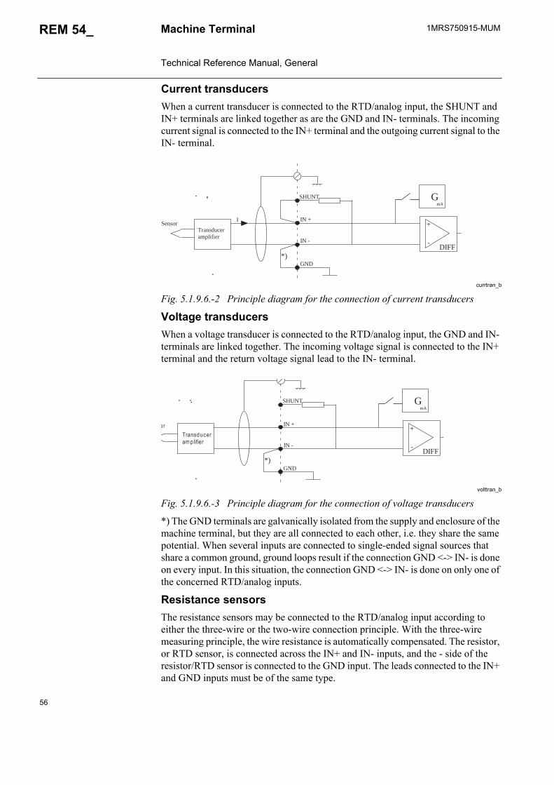
56
1MRS750915-MUMMachine Terminal Technical Reference Manual, General
REM 54_
Current transducersWhen a current transducer is connected to the RTD/analog input, the SHUNT and IN+ terminals are linked together as are the GND and IN- terminals. The incoming current signal is connected to the IN+ terminal and the outgoing current signal to the IN- terminal.
currtran_b
Fig. 5.1.9.6.-2 Principle diagram for the connection of current transducers
Voltage transducersWhen a voltage transducer is connected to the RTD/analog input, the GND and IN- terminals are linked together. The incoming voltage signal is connected to the IN+ terminal and the return voltage signal lead to the IN- terminal.
volttran_b
Fig. 5.1.9.6.-3 Principle diagram for the connection of voltage transducers
*) The GND terminals are galvanically isolated from the supply and enclosure of the machine terminal, but they are all connected to each other, i.e. they share the same potential. When several inputs are connected to single-ended signal sources that share a common ground, ground loops result if the connection GND <-> IN- is done on every input. In this situation, the connection GND <-> IN- is done on only one of the concerned RTD/analog inputs.
Resistance sensorsThe resistance sensors may be connected to the RTD/analog input according to either the three-wire or the two-wire connection principle. With the three-wire measuring principle, the wire resistance is automatically compensated. The resistor, or RTD sensor, is connected across the IN+ and IN- inputs, and the - side of the resistor/RTD sensor is connected to the GND input. The leads connected to the IN+ and GND inputs must be of the same type.
SHUNT
IN -
GND
I
*)
IN +
GmA
DIFF
+
-
Transducer amplifier
Sensor
SHUNT
IN -
GND *)
IN +
GmA
DIFF
+
-
Transducer am p lifier
o r
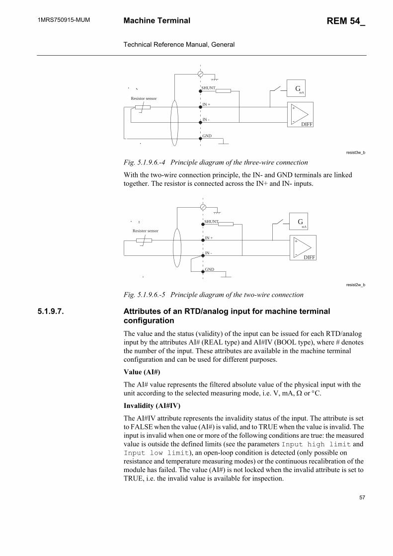
1MRS750915-MUM REM 54_
57
Machine Terminal Technical Reference Manual, General
resist3w_b
Fig. 5.1.9.6.-4 Principle diagram of the three-wire connection
With the two-wire connection principle, the IN- and GND terminals are linked together. The resistor is connected across the IN+ and IN- inputs.
resist2w_b
Fig. 5.1.9.6.-5 Principle diagram of the two-wire connection
5.1.9.7. Attributes of an RTD/analog input for machine terminal configurationThe value and the status (validity) of the input can be issued for each RTD/analog input by the attributes AI# (REAL type) and AI#IV (BOOL type), where # denotes the number of the input. These attributes are available in the machine terminal configuration and can be used for different purposes.
Value (AI#)
The AI# value represents the filtered absolute value of the physical input with the unit according to the selected measuring mode, i.e. V, mA, or C.
Invalidity (AI#IV)
The AI#IV attribute represents the invalidity status of the input. The attribute is set to FALSE when the value (AI#) is valid, and to TRUE when the value is invalid. The input is invalid when one or more of the following conditions are true: the measured value is outside the defined limits (see the parameters Input high limit and Input low limit), an open-loop condition is detected (only possible on resistance and temperature measuring modes) or the continuous recalibration of the module has failed. The value (AI#) is not locked when the invalid attribute is set to TRUE, i.e. the invalid value is available for inspection.
SHUNT
IN -
GND
IN +
GmA
DIFF
+
-
Resistor sensor
SHUNT
IN -
GND
IN +
GmA
DIFF
+
-
Resistor sensor

58
1MRS750915-MUMMachine Terminal Technical Reference Manual, General
REM 54_
5.1.9.8. RTD/analog input configuration exampleThe RTD/analog inputs are supported in the Relay Configuration Tool by the general measurement function blocks MEAI1...MEAI8. As an example, to monitor temperature using a PT100 sensor, the measured value of the RTD/analog input is connected to the function block by connecting the value attribute RTD1_6_AI1 to the RawAI input of the function block. The output HighAlarm is used to activate a relay contact when the temperature exceeds a preset limit. The measured temperature is displayed on the MIMIC view of the HMI by the connected MMIDATA1 function block. To avoid unnecessary activation of the relay contact in case of a fault, the corresponding invalid attribute of the RTD/analog input RTD1_6_AI1IV is connected to the IV input of the function block.
A060253
Fig. 5.1.9.8.-1 RTD/analog input configuration example
5.1.9.9. Self-supervisionEach input sample is validated before it is fed into the filter algorithm. The samples are validated by measuring an internally set reference voltage immediately after the inputs are sampled. If the measured offset voltage deviates from the set value more than 1.5% of the measuring range, the sample is discarded. If the fault continues longer than for the set filter time, the invalid attributes of all inputs are set to TRUE to indicate a hardware fault. Should the measurement succeed later, the invalid attributes are reset to FALSE. This prevents most sudden hardware faults from affecting the measured value before the invalid attribute is set. To ensure that the specified measurement accuracy is met, a more thorough test of the hardware is performed by the continuous recalibration procedure which will catch errors that degrade the measurement accuracy.

1MRS750915-MUM REM 54_
59
Machine Terminal Technical Reference Manual, General
5.1.9.10. CalibrationThe RTD/analog module is calibrated at the factory. To be able to maintain the specified accuracy in spite of aging and varying temperature, the card also includes special hardware to allow self-recalibration on the field. This recalibration procedure runs continuously, even when no measurements are activated, to ensure that the card is always optimally calibrated. If the recalibration procedure fails, the reason is a hardware failure. In this case the card's measurement accuracy is no longer obtained, and the invalidity attributes of all inputs are set to TRUE. However, the card continues updating the measured input values, and if the invalidity attributes are not used in the machine terminal configuration, the situation could go unnoticed. Should the recalibration succeed later, the invalidity attributes return to normal operation.
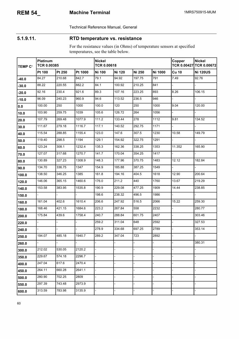
60
1MRS750915-MUMMachine Terminal Technical Reference Manual, General
REM 54_
5.1.9.11. RTD temperature vs. resistanceFor the resistance values (in Ohms) of temperature sensors at specified temperatures, see the table below.
TEMP CPlatinumTCR 0.00385
NickelTCR 0.00618
Copper TCR 0.00427
NickelTCR 0.00672
Pt 100 Pt 250 Pt 1000 Ni 100 Ni 120 Ni 250 Ni 1000 Cu 10 Ni 120US
-40.0 84.27 210.68 842.7 79.1 94.92 197.75 791 7.49 92.76
-30.0 88.22 220.55 882.2 84.1 100.92 210.25 841 - -
-20.0 92.16 230.4 921.6 89.3 107.16 223.25 893 8.26 106.15
-10.0 96.09 240.23 960.9 94.6 113.52 236.5 946 - -
0.0 100.00 250 1000 100.0 120 250 1000 9.04 120.00
10.0 103.90 259.75 1039 105.6 126.72 264 1056 - -
20.0 107.79 269.48 1077.9 111.2 133.44 278 1112 9.81 134.52
30.0 111.67 279.18 1116.7 117.1 140.52 292.75 1171 - -
40.0 115.54 288.85 1155.4 123.0 147.6 307.5 1230 10.58 149.79
50.0 119.40 298.5 1194 129.1 154.92 322.75 1291 - -
60.0 123.24 308.1 1232.4 135.3 162.36 338.25 1353 11.352 165.90
70.0 127.07 317.68 1270.7 141.7 170.04 354.25 1417 - -
80.0 130.89 327.23 1308.9 148.3 177.96 370.75 1483 12.12 182.84
90.0 134.70 336.75 1347 154.9 185.88 387.25 1549 - -
100.0 138.50 346.25 1385 161.8 194.16 404.5 1618 12.90 200.64
120.0 146.06 365.15 1460.6 176.0 211.2 440 1760 13.67 219.29
140.0 153.58 383.95 1535.8 190.9 229.08 477.25 1909 14.44 238.85
150.0 - - - 198.6 238.32 496.5 1986 - -
160.0 161.04 402.6 1610.4 206.6 247.92 516.5 2066 15.22 259.30
180.0 168.46 421.15 1684.6 223.2 267.84 558 2232 - 280.77
200.0 175.84 439.6 1758.4 240.7 288.84 601.75 2407 - 303.46
220.0 - - - 259.2 311.04 648 2592 - 327.53
240.0 - - - 278.9 334.68 697.25 2789 - 353.14
250.0 194.07 485.18 1940.7 289.2 347.04 723 2892 - -
260.0 - - - - - - - - 380.31
300.0 212.02 530.05 2120.2 - - - - - -
350.0 229.67 574.18 2296.7 - - - - - -
400.0 247.04 617.6 2470.4 - - - - - -
450.0 264.11 660.28 2641.1 - - - - - -
500.0 280.90 702.25 2809 - - - - - -
550.0 297.39 743.48 2973.9 - - - - - -
600.0 313.59 783.98 3135.9 - - - - - -

1MRS750915-MUM REM 54_
61
Machine Terminal Technical Reference Manual, General
5.1.10. Analog outputsThe machine terminals equipped with an RTD/analog module have four general purpose 0...20 mA analog current outputs. All outputs are galvanically isolated from the supply and enclosure of the machine terminal and from each other.
For technical data of the analog outputs, refer to Table 5.2.1-7 on page 80.
The parameters and events for the analog outputs are included in the event and parameter lists on the CD-ROM Technical Descriptions of Functions (see “Related documents” on page 8).
5.1.10.1. Selection of analog output rangeThe outputs can be set to two different current ranges with the Output range parameters in the menu Configuration/RTD1/Output #.
5.1.10.2. Attributes of an analog output for machine terminal configurationThe status (value) and the validity of the output can be issued for each analog output by the attributes AO# (REAL type) and AO#IV (BOOL type), where # denotes the number of the output. These attributes are available in the machine terminal configuration and can be used for different purposes.
Value (AO#)
The value written to AO# is transferred to a current signal at the output. The output response time is 85 ms, consisting of the software delay and the rise time of the analog output, counted from the moment when the value attribute is updated in the configuration program.
Invalidity (AO#IV)
The AO#IV attribute represents the invalidity status of the output. The attribute is set to FALSE when the value (AO#) is valid, i.e. an equal amount of current is flowing through the output, and to TRUE when the value is invalid, i.e. the current at the output is different from the value of AO#. When the AO#IV attribute is TRUE, this indicates one of two situations: either the current loop connected to the output is broken or the value attribute is written with a value outside the range defined by
REM543/REM545 + RTD1Analog outputs RTD1_6_AO1
RTD1_6_AO2RTD1_6_AO3RTD1_6_AO4
Parameter Values DefaultOutput range 0 = 0...20 mA
1 = 4...20 mA0...20 mA
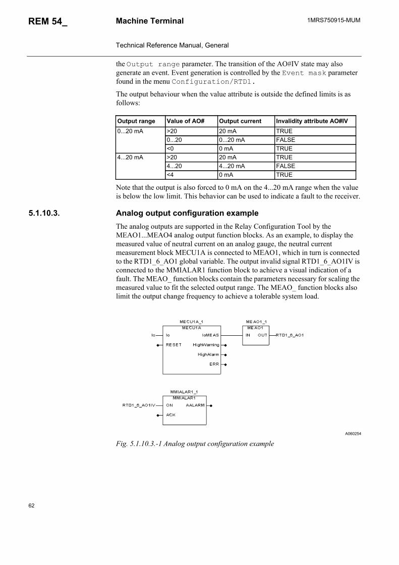
62
1MRS750915-MUMMachine Terminal Technical Reference Manual, General
REM 54_
the Output range parameter. The transition of the AO#IV state may also generate an event. Event generation is controlled by the Event mask parameter found in the menu Configuration/RTD1.
The output behaviour when the value attribute is outside the defined limits is as follows:
Note that the output is also forced to 0 mA on the 4...20 mA range when the value is below the low limit. This behavior can be used to indicate a fault to the receiver.
5.1.10.3. Analog output configuration example The analog outputs are supported in the Relay Configuration Tool by the MEAO1...MEAO4 analog output function blocks. As an example, to display the measured value of neutral current on an analog gauge, the neutral current measurement block MECU1A is connected to MEAO1, which in turn is connected to the RTD1_6_AO1 global variable. The output invalid signal RTD1_6_AO1IV is connected to the MMIALAR1 function block to achieve a visual indication of a fault. The MEAO_ function blocks contain the parameters necessary for scaling the measured value to fit the selected output range. The MEAO_ function blocks also limit the output change frequency to achieve a tolerable system load.
A060254
Fig. 5.1.10.3.-1 Analog output configuration example
Output range Value of AO# Output current Invalidity attribute AO#IV0...20 mA >20 20 mA TRUE
0...20 0...20 mA FALSE<0 0 mA TRUE
4...20 mA >20 20 mA TRUE4...20 4...20 mA FALSE<4 0 mA TRUE
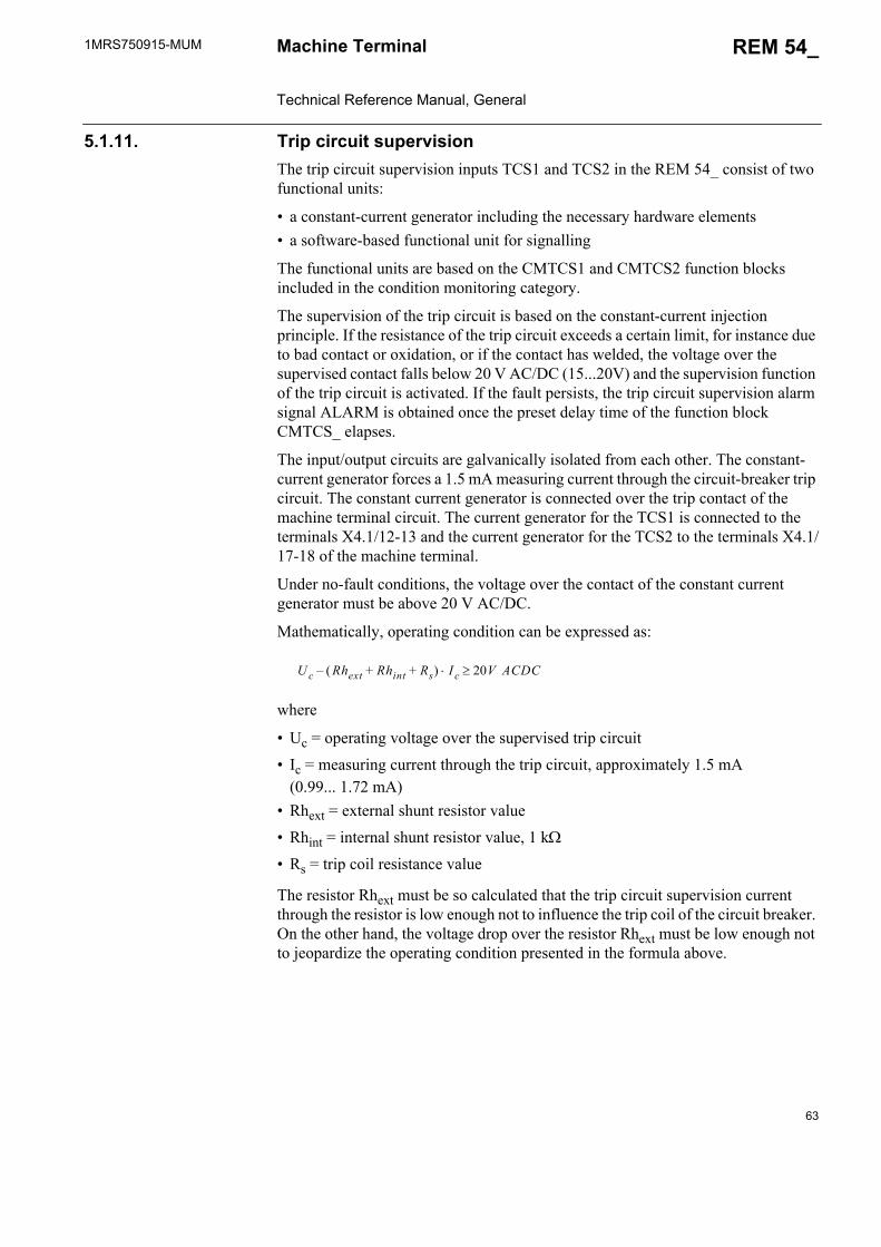
1MRS750915-MUM REM 54_
63
Machine Terminal Technical Reference Manual, General
5.1.11. Trip circuit supervisionThe trip circuit supervision inputs TCS1 and TCS2 in the REM 54_ consist of two functional units:
• a constant-current generator including the necessary hardware elements • a software-based functional unit for signalling
The functional units are based on the CMTCS1 and CMTCS2 function blocks included in the condition monitoring category.
The supervision of the trip circuit is based on the constant-current injection principle. If the resistance of the trip circuit exceeds a certain limit, for instance due to bad contact or oxidation, or if the contact has welded, the voltage over the supervised contact falls below 20 V AC/DC (15...20V) and the supervision function of the trip circuit is activated. If the fault persists, the trip circuit supervision alarm signal ALARM is obtained once the preset delay time of the function block CMTCS_ elapses.
The input/output circuits are galvanically isolated from each other. The constant-current generator forces a 1.5 mA measuring current through the circuit-breaker trip circuit. The constant current generator is connected over the trip contact of the machine terminal circuit. The current generator for the TCS1 is connected to the terminals X4.1/12-13 and the current generator for the TCS2 to the terminals X4.1/17-18 of the machine terminal.
Under no-fault conditions, the voltage over the contact of the constant current generator must be above 20 V AC/DC.
Mathematically, operating condition can be expressed as:
where
• Uc = operating voltage over the supervised trip circuit• Ic = measuring current through the trip circuit, approximately 1.5 mA
(0.99... 1.72 mA)• Rhext = external shunt resistor value• Rhint = internal shunt resistor value, 1 k • Rs = trip coil resistance value
The resistor Rhext must be so calculated that the trip circuit supervision current through the resistor is low enough not to influence the trip coil of the circuit breaker. On the other hand, the voltage drop over the resistor Rhext must be low enough not to jeopardize the operating condition presented in the formula above.
U c Rhext Rhint Rs+ + I c 20V ACDC–
64
1MRS750915-MUMMachine Terminal Technical Reference Manual, General
REM 54_
The following values are recommended for the resistor Rhext in refer to chapter 5.1.11.-1 below:
A060255
Fig. 5.1.11.-1 Operating principle of the trip circuit supervision (TCS) function
5.1.11.1. Configuring the trip circuit supervision CMTCS_The Relay Configuration Tool can be used to connect the trip circuit supervision input status signals to the function blocks CMTCS1 and CMTCS2. The configuration of the blocking signal is user-specific and can only be defined in the machine terminal configuration. The trip circuit supervision inputs in the machine terminal configuration are as follows:
TCS1 and TCS2 inputs in REM 543 and REM 545:
For more information about the trip circuit supervision functions CMTCS1 and CMTCS2, refer to the Technical Descriptions of Functions CD-ROM.
Operating voltage Uc Shunt resistor Rhext
48 V DC 1.2 k, 5 W60 V DC 5.6 k, 5 W110 V DC 22 k, 5 W220 V DC 33 k, 5 W
'1
�
�2
�
�2�3%�*�
4�4�3
%�*�
�*
%�**%4%� 4�4�3
�
,# 5
�
�
���� ��
6�
�
Trip Circuit Supervision 1 input PS1_4_TCS1Trip Circuit Supervision 2 input PS1_4_TCS2

1MRS750915-MUM REM 54_
65
Machine Terminal Technical Reference Manual, General
5.1.12. Self-supervision (IRF)The machine terminal is provided with an extensive self-supervision system. The self-supervision system handles run-time fault situations and informs the user of faults via the HMI and LON/SPA communication. See also Table 5.2.1-12 on page 83.
5.1.12.1. Fault indicationThe self-supervision signal output operates on the closed circuit principle. Under normal conditions the output relay is energized and the contact gap 3-5 is closed. Should the auxiliary power supply fail or an internal fault be detected, the contact gap 3-5 is opened.
A060256
Fig. 5.1.12.1.-1 Self-supervision output (IRF)
When a fault has been detected, the green Ready indicator starts blinking, a fault indication text is displayed on the HMI and an event, E57, is generated over the serial communication. The fault indication text on the HMI consists of two rows as shown below:
A060264
Fig. 5.1.12.1.-2 IRF indication text
Fault indication has the highest priority on the HMI and cannot be overrun by any other HMI indication. The fault indication text is displayed until cleared by pressing the C button for 2 seconds. Then the green READY indicator still remains blinking.
If the internal fault disappears the fault indication text remains on the display unless it has been cleared, but the green READY indicator stops blinking. In addition, an event E56 is generated over the serial communication.
5.1.12.2. Fault codesWhen an internal fault appears in REM 54_, the self-supervision system generates an IRF code that indicates the type of the fault. The fault code can be read from the machine terminal main menu Status/General/IRF code. The code indicates the first internal fault detected by the self-supervision system.
��$ ��$
/
�
�
/
�
�
��� � ���&����� $!�� ���&�����
� � � � � � � � � � � � � � � � � � � � � � � � � �

66
1MRS750915-MUMMachine Terminal Technical Reference Manual, General
REM 54_
The following table gives an overview of the fault origin.
5.1.13. Serial communicationThe machine terminal has three serial communication ports, one on the front panel and two on the rear panel.
5.1.13.1. Serial communication port assignmentThe bus communication protocol for the rear interface RS-232 (connector X3.2) is selected via the Protocol 2 setting parameter and the bus communication protocol for the rear interface RS-485 (connector X3.3) is selected via the Protocol 3 setting parameter. These parameters can be modified by using the local menu (Communication/General)or by using the Relay Setting Tool.
The following table shows supported parallel communication protocols on the front and the rear connectors of the REM 54_ machine terminals.
5.1.13.2. SPA/Modbus communication on the rear connector X3.2The 9-pin D-type subminiature male connector (RS-232 connection) on the rear panel connects the machine terminal to the distribution automation system via the SPA bus or the Modbus. The RER 123 fibre-optic Bus Connection Module is used
Do not reset the machine terminal before reading the IRF code. The code should be supplied when overhaul is ordered.
Codes Explanation0 -> Faults related to a module of the machine terminal, e.g. the MIMIC
card, BIO card or RTD/analog module3000 -> Faults related to the parameter database6000 -> Faults related to the analog measurement inputs7000 -> Software faults15000 -> Faults related to testing
Connectors/Communication parameters
X3.2/Protocol 2 X3.3/Protocol 3 Front connectorSPA LON SPA
- SPA SPAModbus - SPAModbus SPA -
IEC 61850 LON (SMS) SPAIEC 61850 SPA (SMS) -IEC 61850 - SPAProfibus LON (SMS) SPAProfibus SPA (SMS) -Profibus - SPA
1MRS750915-MUM REM 54_
67
Machine Terminal Technical Reference Manual, General
for connecting the machine terminal to the fibre-optic communication bus for SPA protocol. The interface between the machine terminal and a RS-485 communication bus can be made through the RER 133 Bus Connection Module.
5.1.13.3. IEC 61850 communication by using SPA-ZC 400 on the rear connector X3.2The 9-pin D-type subminiature male connector (RS-232 connection) on the rear panel connects the machine terminal to the distribution automation system via the IEC 61850 protocol. In the IEC 61850 mode, the SPA-ZC 400 Bus Connection Module is needed.
In the IEC 61850 mode, the baud rate for relay port X3.2 is set to 38400. Furthermore, the mode includes a limited IEC 61850 GOOSE message support when available in SPA-ZC 400.
5.1.13.4. Profibus-DPV1 communication by using SPA-ZC 302 on the rear connector X3.2The 9-pin D-type subminiature male connector (RS-232 connection) on the rear panel connects the machine terminal to the distribution automation system via the Profibus protocol. The interface between the machine terminal and Profibus can be made through the SPA-ZC 302 Gateway.
In the Profibus mode, the baud rate for relay port X3.2 is set to 38400. The SPA-ZC 302 Gateway should be set to the same baud rate. If the SPA-ZC 302 Gateway is connected to multiple terminals, the “Protocol 2” parameter should be set to SPA mode and the SPA baud rate for port X3.2 to 19200.
5.1.13.5. LON/SPA bus communication on the rear connector X3.3The 9-pin D-type subminiature female connector (RS-485 connection) on the rear panel connects the machine terminal to the distribution automation system via the SPA bus or the LON bus. The fibre-optic interface module type RER 103 is used for connecting the machine terminal to the fibre-optic communication bus. The module RER 103 supports both SPA bus and LON bus communication.
The other communication parameters for the rear RS-485 interface are set also via the Communication menu.
5.1.13.6. Front panel optical RS-232 connection for a PCThe optical connector on the front panel isolates the PC galvanically from the machine terminal. The front connector for the PC is standardized for ABB relay products and requires a specific opto-cable (ABB art. No 1MKC950001-2). The cable is connected to the serial RS-232 port of the PC.
68
1MRS750915-MUMMachine Terminal Technical Reference Manual, General
REM 54_
The front panel is intended for the connection of a PC when configuring the machine terminal with the CAP 50_ and SMS 510 tools. The front connector uses the SPA bus protocol.
5.1.13.7. Communication parametersThe communication parameters for the SPA, Modbus and LON protocols are set in the Communication menu of the terminal and activated by storing the changes and resetting the device. These parameters cannot be changed with the Relay Setting Tool.
The SPA bus protocol uses an asynchronous serial communication protocol (1 start bit, 7 data bits + even parity, 1 stop bit) with adjustable data transfer rate (Baud rate, default 9.6 kbps) of the communication parameters and SPA address (slave number).
The SPA communication parameters are the same for all SPA communication via the optical front connector, the rear RS-485 and RS-232 connectors. The SPA address is the same also for transparent SPA communication on the LON protocol.
Parameter Value Default value ExplanationSPA address 0...999 1 Slave number for communicationBaud rate 4800; 9600; 19200 bps 9600 Data transfer rate for communicationRear connection Connect Activate rear SPA connectiona
a. This functionality is valid only in machine terminal revisions of releases prior to Release 2.0. The parameter is accessible only via serial communication. SPA communication on the front connector inhibits the rear X3.3 SPA communication and the transparent SPA communication on the LON protocol and remains inhibited for one minute after the SPA communication has stopped. It is possible to release this blocking situation by writing the value 1 to the V202 variable.

1MRS750915-MUM REM 54_
69
Machine Terminal Technical Reference Manual, General
Adjustable LON serial communication parameters are Subnet number, Node number and Bit rate.
The bit rate 78.1 kbps on the LON protocol is used for the FTT-10 serial communication network using the RER 115 module connected to the X3.3 connector. The bit rate 1250 kbps on the LON protocol is used for the optical serial communication network using the RER 103 module connected to the X3.3 connector.
The Modbus protocol has two serial transmission modes: ASCII and RTU. These modes define the bit contents of the message fields transmitted in the network. Adjustable Modbus serial communication parameters are shown in the table below.
The SPA address and the Subnet/Node number on the LON are used for identifying the device from the protocol’s point of view and they are independent of each other.
For more information, see Table 5.2.1-11 on page 82.
5.1.13.8. Parallel communication supportWhen SPA is used, the rear side communication is not stopped when the front connector is “active”. This enables e.g. uploading of the disturbance records without affecting the communication to the upper level.
Moreover, if LON is selected as a communication protocol and the front connector is “active”, transparent SPA write commands are not inhibited via the LON bus.1
Parameter Value Default value ExplanationSubnet number 1...255 1 LON subnet numberNode number 1...127 1 LON node numberBit rate 78.1; 1250 kbps 1250 LON communication speed
Parameter Value Default value ExplanationUnit Address 1...247 1 Address of the unit in the Modbus networkCRC Order Low/High; High/Low Low/High The order of CRC bytes in the protocol frame
(not used in ASCII mode)Modbus Mode ASCII; RTU RTU ASCII or RTU modeBaud rate 300; 1200; 2400;
4800;9600;19200 bps9600 Communication speed of the Modbus
protocolNo of stop bits 1...2 1 Number of stop bitsNext char. TO 0...65535 ms 0 Next character time-outEnd of frame TO 2...65535 ms 10 End of frame time-outParity NONE; ODD; EVEN EVEN Parity settingNo of data bits 5,6,7,8 8 Number of data bits
1. Parallel communication is restricted prior to Release 2.0, refer to section “Release 2.0” on page 95.
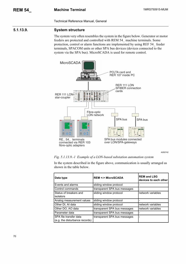
70
1MRS750915-MUMMachine Terminal Technical Reference Manual, General
REM 54_
5.1.13.9. System structureThe system very often resembles the system in the figure below. Generator or motor feeders are protected and controlled with REM 54_ machine terminals. Some protection, control or alarm functions are implemented by using REF 54_ feeder terminals, SPACOM units or other SPA bus devices (devices connected to the system via the SPA bus). MicroSCADA is used for remote control.
A050742
Fig. 5.1.13.9.-1 Example of a LON-based substation automation system
In the system described in the figure above, communication is usually arranged as shown in the table below.
Data type REM <-> MicroSCADA REM and LSG
devices to each otherEvents and alarms sliding window protocol -Control commands transparent SPA bus messages -Status of breakers and isolators
sliding window protocol network variables
Analog measurement values sliding window protocol -Other DI, AI data sliding window protocol network variablesOther DO, AO data transparent SPA bus messages network variablesParameter data transparent SPA bus messages -SPA file transfer data(e.g. the disturbance records)
transparent SPA bus messages -
�
�
��� ���
6���'*�
278�9�)�(((��'��3:;2:</�9�'���=�/�9��;'���>�?
� 6$�888888+)�'�+'�+
��/�9��;'���>��?/�9����;������>?�/�9����;������>�?
���@�
����A
�6���
6���'*�
278�9�)�(((��'��3:;2:</�9�'���=�/�9��;'���>�?
� 6$�888888+)�'�+'�+
��/�9��;'���>��?/�9����;������>?�/�9����;������>�?
���@�
����A
�6���
�
�
��� ���
*)4 �!� �&!�� ������&��� ���"*)4���78�
��� ��� �� ����������& �� ��� �#/9��������� &����
��� ��� ���������!���
*)4 �!� *)4 �!�
$������������ ��7���
3����*�4:4
)��%4 ��& �&��� �#- ����& )�
��� ��� ���*$���� �����������&�
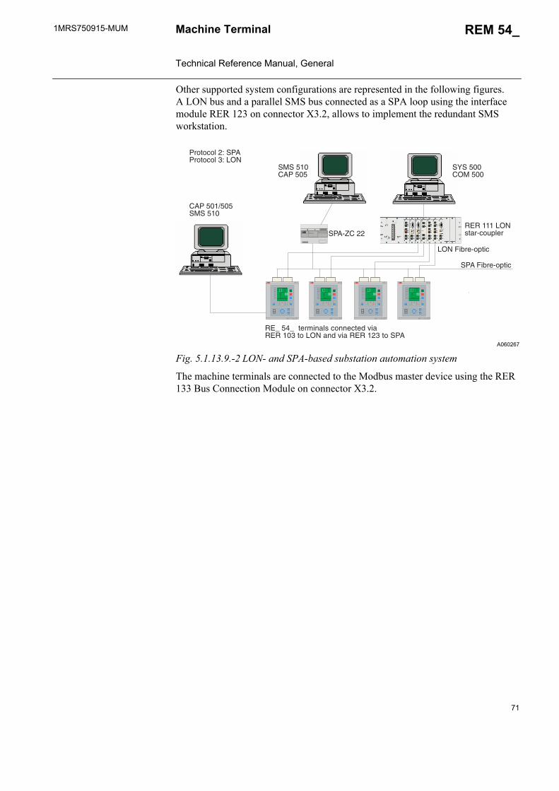
1MRS750915-MUM REM 54_
71
Machine Terminal Technical Reference Manual, General
Other supported system configurations are represented in the following figures. A LON bus and a parallel SMS bus connected as a SPA loop using the interface module RER 123 on connector X3.2, allows to implement the redundant SMS workstation.
A060267
Fig. 5.1.13.9.-2 LON- and SPA-based substation automation system
The machine terminals are connected to the Modbus master device using the RER 133 Bus Connection Module on connector X3.2.
6���'*�
278�9�)�(((��'��3:;2:</�9�'���=�/�9��;'���>�?
� 6$�888888+)�'�+'�+
��/�9��;'���>��?/�9����;������>?�/�9����;������>�?
���@�
����A
�6���
6���'*�
278�9�)�(((��'��3:;2:</�9�'���=�/�9��;'���>�?
� 6$�888888+)�'�+'�+
��/�9��;'���>��?/�9����;������>?�/�9����;������>�?
���@�
����A
�6���
6���'*�
278�9�)�(((��'��3:;2:</�9�'���=�/�9��;'���>�?
� 6$�888888+)�'�+'�+
��/�9��;'���>��?/�9����;������>?�/�9����;������>�?
���@�
����A
�6���
6���'*�
278�9�)�(((��'��3:;2:</�9�'���=�/�9��;'���>�?
� 6$�888888+)�'�+'�+
��/�9��;'���>��?/�9����;������>?�/�9����;������>�?
���@�
����A
�6���
$��1B� �� *)4�;� ,,
*<* �##��3 �##
*3* ��#�4) �#�
)������� ,= *)4)������� /= ���
*)4 $���������
��� ��� �� ���� ������& ����� �#/ �� ��� �& �� ��� �,/ �� *)4
��� $���������
��� ��� ���������!���
�4) �#�"�#�*3* ��#
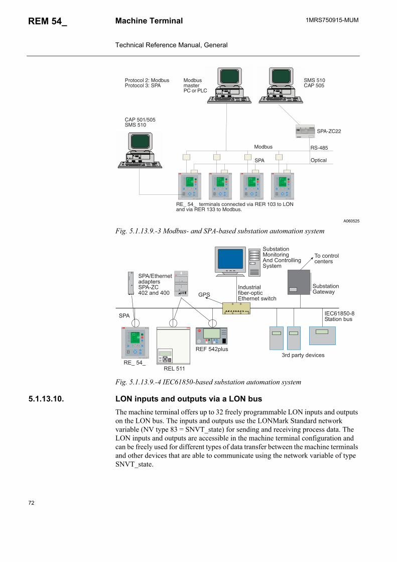
72
1MRS750915-MUMMachine Terminal Technical Reference Manual, General
REM 54_
A060525
Fig. 5.1.13.9.-3 Modbus- and SPA-based substation automation system
Fig. 5.1.13.9.-4 IEC61850-based substation automation system
5.1.13.10. LON inputs and outputs via a LON busThe machine terminal offers up to 32 freely programmable LON inputs and outputs on the LON bus. The inputs and outputs use the LONMark Standard network variable (NV type 83 = SNVT_state) for sending and receiving process data. The LON inputs and outputs are accessible in the machine terminal configuration and can be freely used for different types of data transfer between the machine terminals and other devices that are able to communicate using the network variable of type SNVT_state.
6���'*�
278�9�)�(((��'��3:;2:</�9�'���=�/�9��;'���>�?
� 6$�888888+)�'�+'�+
��/�9��;'���>��?/�9����;������>?�/�9����;������>�?
���@�
����A
�6���
6���'*�
278�9�)�(((��'��3:;2:</�9�'���=�/�9��;'���>�?
� 6$�888888+)�'�+'�+
��/�9��;'���>��?/�9����;������>?�/�9����;������>�?
���@�
����A
�6���
6���'*�
278�9�)�(((��'��3:;2:</�9�'���=�/�9��;'���>�?
� 6$�888888+)�'�+'�+
��/�9��;'���>��?/�9����;������>?�/�9����;������>�?
���@�
����A
�6���
6���'*�
278�9�)�(((��'��3:;2:</�9�'���=�/�9��;'���>�?
� 6$�888888+)�'�+'�+
��/�9��;'���>��?/�9����;������>?�/�9����;������>�?
���@�
����A
�6���
$��1B� ��
*3* ��#�4) �#�
3�&�!� ���)� �� )��
)������� ,= 3�&�!�)������� /= *)4
��� ��� �� ���� ������& �� ��� �#/ �� ����& �� ��� �// �� 3�&�!�(
*)4�;�,,
�4) �#�"�#�*3* ��#
�*��>�
������*)4
3�&�!�
6���'��6�C�'*C
6���'*�D47�
6���'*�
278�9�)�(((��'��3:;2:</�9�'���=�/�9��;'���>�?
� 6$�888888+)�'�+'�+
��/�9��;'���>��?/�9����;������>?�/�9����;������>�?
���@�
����A
�6���
�
�
03�D20%E�3.F�:.�
$��
��$�/37�%0�24<�G.01�D%�:�%!.0/.%����%:!
-��:�/%0�4:./%.0�
$7G�%2%��/�2%.�2E
�����)'�1)$%2%��/�G7�
$��;�%!.0/.%232D%.0�$��1B�*���2/3�*��
$7G�%2%��/ �/�%�0�/ �/3���/%0�44�/ $E�%.5

1MRS750915-MUM REM 54_
73
Machine Terminal Technical Reference Manual, General
lonlog_b
Fig. 5.1.13.10.-1 Principle of connecting LON inputs and outputs to logic functions of the machine terminal
The SNVT_state can be used to communicate the state of a set of 1 to 16 Boolean values. Each bit indicates the state of the Boolean value with, for example, the following interpretations:
The value field shows the current value of the digital inputs or outputs at the time of reporting, or the latest value reported from the concerned device.
The SNVT_state can be used to transfer the state of 1 to 16 digital inputs, or to set the state of 1 to 16 output bits or digital set-points.
0 1
off on inactive activedisabled enabledlow highfalse truenormal alarm
��
/F�� /F�� /F��
�;�
6���'*C
��
/F�� /F�� /F��
�;�
6���'*C
��
/F��
6�C�'*C
$H$ ���
���
6�C�'*C
��
/F�� /F�� /F��
6�C�'*C
/F�� /F�� /F��
��
/F��/F��
�/%.014�:@�/
�4�:@�/
�D././2G4.
�4��../2G4.
�4��.
�D./6.�.0F.
�/%.014�:@�/
�D././2G4.
�4��../2G4.
�4��.
�D./6.�.0F.
�/%.014�:@�/
�4�:@�/
�D././2G4.
�4��../2G4.
�4��.
�D./6.�.0F.
$.4.:%;�8.:7%.
�4�:@�/
�;� �;� �;�
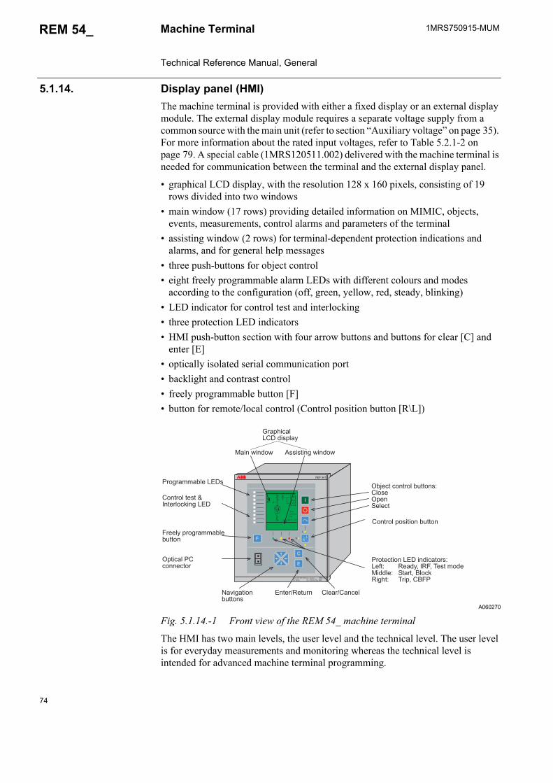
74
1MRS750915-MUMMachine Terminal Technical Reference Manual, General
REM 54_
5.1.14. Display panel (HMI)The machine terminal is provided with either a fixed display or an external display module. The external display module requires a separate voltage supply from a common source with the main unit (refer to section “Auxiliary voltage” on page 35). For more information about the rated input voltages, refer to Table 5.2.1-2 on page 79. A special cable (1MRS120511.002) delivered with the machine terminal is needed for communication between the terminal and the external display panel.
• graphical LCD display, with the resolution 128 x 160 pixels, consisting of 19 rows divided into two windows
• main window (17 rows) providing detailed information on MIMIC, objects, events, measurements, control alarms and parameters of the terminal
• assisting window (2 rows) for terminal-dependent protection indications and alarms, and for general help messages
• three push-buttons for object control • eight freely programmable alarm LEDs with different colours and modes
according to the configuration (off, green, yellow, red, steady, blinking)• LED indicator for control test and interlocking• three protection LED indicators • HMI push-button section with four arrow buttons and buttons for clear [C] and
enter [E]• optically isolated serial communication port• backlight and contrast control• freely programmable button [F]• button for remote/local control (Control position button [R\L])
A060270
Fig. 5.1.14.-1 Front view of the REM 54_ machine terminal
The HMI has two main levels, the user level and the technical level. The user level is for everyday measurements and monitoring whereas the technical level is intended for advanced machine terminal programming.
�0� 02552G4.������GI.:%�:�/%0�4�G7%%�/�J�4��.�D./$.4.:%
��/%0�4�D���%��/�G7%%�/
�D%�:24���:�//.:%�0
�0..4E�D0� 02552G4.G7%%�/
��/%0�4�%.�%�K�/%.04�:@�/ ����
�0�%.:%��/������/3�:2%�0�J�.<%J 6.23E,��6�,�-.�%�5�3. �334.J $%20%,��4�:@6� !%J -0�D,�����
�02D!�:24����3��D42E
2�/���/3�� �����%�/ ���/3��
�/%.0;6.%70/ �4.20;�2/:.4�2F� 2%��/G7%%�/�
6���'*�
278�9�)�(((��'��3:;2:</�9�'���=�/�9��;'���>�?
� 6$�888888+)�'�+'�+
��/�9��;'���>��?/�9����;������>?�/�9����;������>�?
�����
?
��
��
�������
� ��������
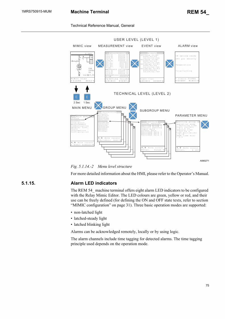
1MRS750915-MUM REM 54_
75
Machine Terminal Technical Reference Manual, General
A060271
Fig. 5.1.14.-2 Menu level structure
For more detailed information about the HMI, please refer to the Operator’s Manual.
5.1.15. Alarm LED indicatorsThe REM 54_ machine terminal offers eight alarm LED indicators to be configured with the Relay Mimic Editor. The LED colours are green, yellow or red, and their use can be freely defined (for defining the ON and OFF state texts, refer to section “MIMIC configuration” on page 31). Three basic operation modes are supported:
• non-latched light• latched-steady light• latched blinking light
Alarms can be acknowledged remotely, locally or by using logic.
The alarm channels include time tagging for detected alarms. The time tagging principle used depends on the operation mode.
�����
?
��
��
�������
� ��������
� � � � � � � � � � � � � �� � � � � � � � � � � �� � � � � � � � � � � � � �� � � � � � � � � � � � � � � �� � � � � � � � � � � � � � � �� � � � � � � � � � � � � � � �� � � � � � � � � � � � � � �� � � � � � � � � � � � � �� � � � � � � � � � � � � � �� � � � � � � � � � � � � � �� � � � � � � � � � � � � � � � � � � � � � � � � ! � �� � � � � � � � � � � � �� � � � � � � � � � � � � �� � � � � " � # � $" � � % � � � � � � � � & � !
' � ( ( ) � * � * $ � � + � �
����-�F�.� ���6 �F�.�
$�6�������>�������?
-���������������>�������?
� ���F�.� ��$6� ��-�F�.�
, - � + $ ) � * � $ � � � .
' / & � * � � � � � ) ( .
0 � � + � $ � ( � $ �
� � ( � $ � � 1 � ) � *
��6� �-�6� ��
�6��� �� ���� ��
��$.: ��$.:
" $ � ( � 1 ( ) � �
2 3 , � � � #
$��6��� ��
3 + � $ � ( ) � � � � � � �4 � � � � ) � ) ( � � ( ) � �' ( � $ ( � 1 � $ $ � � (4 � � � � � 5 � � �3 + � $ � ( � � ( ) � �4 � � � � � � � 0 ) � � � � � � ( ) + � ) � $4 � � � 6 !� 7 7 7 � ( ) � � � � ) � �4 � � �
� 1 ( � � � � � ( ( ) � *' � ( ( ) � * � * $ � � + � �' � ( ( ) � * � * $ � � + � , � � ( $ � � � � ( ( ) � *� � + � ( � � � ( �3 � ( + � ( � � � ( �8 � 1 � $ � � � � � � ( � � �8 � 1 � $ � � � � � � ( � � 8 � 1 � $ � � � � � � ( � � �
� � $ � 9 �: � ( ' ( � $ (2 7 / � � � #2 7 / � � ) * 92 7 / � � � (2 3 , � � � #2 3 , � � ) * 92 3 , � � � (2 " ' � � � #2 " ' � � ) * 92 � , � ' ( �2 � , � ' ( 0 3 � � � � �
� + � � ( ) � * � � � � � � � : � : � , � � 7 � 7 2 0 �
: � : � , � � ) � #� � � � 8 : � � � : 7 � ' �
: 7 � ' � 8 7 : 7 2 0 7 � 7 2 0 '2 3 , � � � # � � � ; 7 �
� � � � � � � ! < � < � � � �
2 3 , � � � # � � � ; 7 � � � � � � � � ! < � < � � � � �
2 3 , � � ) * 9 � � ; 7 � � � � � � � � < < � 6 �
2 3 , � � ) * 9 � � ; 7 � � � � � � � � < < � 6 & �
7 � � � ( � � ) (� : � : � , � � 7 � 7 2 0 �
, � 1 � � � $ � � � � 8 : � 7 � 7 2 0 � � : � : � , �
� = �� : � � � � 1 � $ � $7 � : � : � , � ' � � � � � � �
' ( � ( � " $ � ( � 1 ( ) � �, � � ( $ � �, � � � � � � � ) ( �: � � � $ � � � � (, � � � � � ) 1 � ( ) � �> � � � $ � � � � � � 1 �0 � ( � � � � $ � � ( ) � �, � � � ) * � $ � ( ) � �
: � � 2 � : 7 2 �
� = �� : � � � � 1 � $ � $�: � ) � : � � � � � 2 � 5 ( �
� = �� : � � � � 1 � $ � $�" $ � � � � � � " � $ � � � �
� = �� : � � � � 1 � $ � $�" $ � � � � � � � � 7 � � (
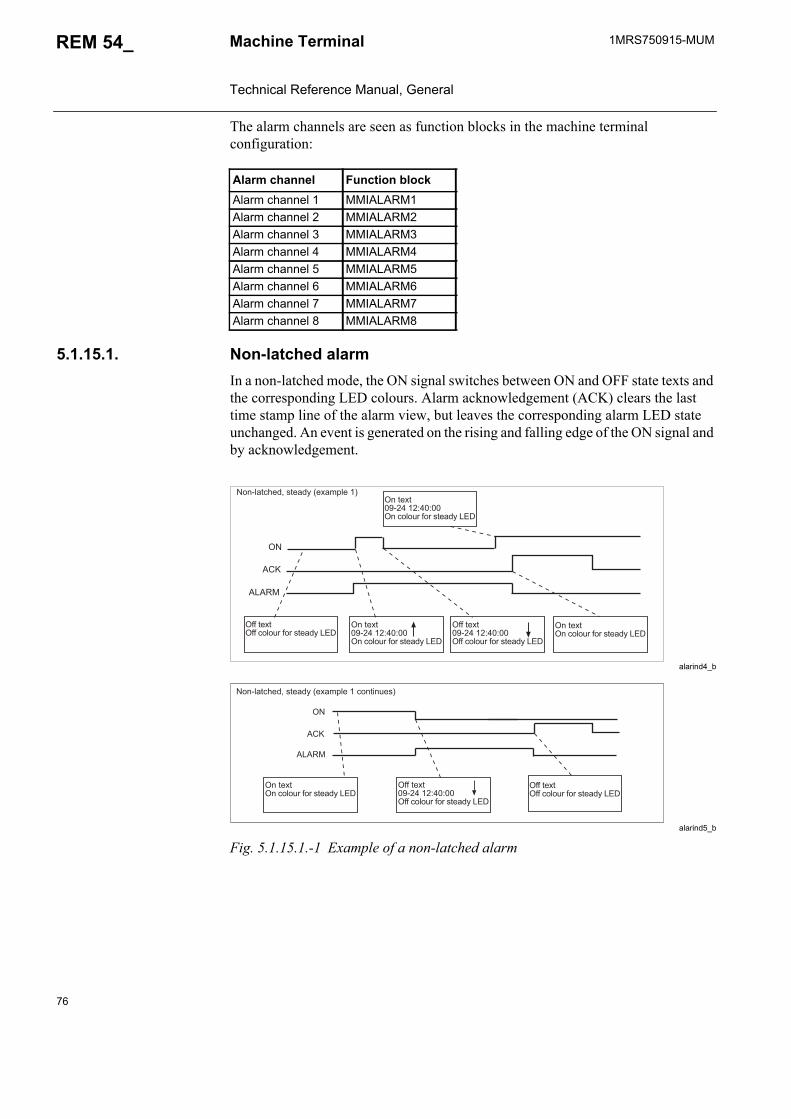
76
1MRS750915-MUMMachine Terminal Technical Reference Manual, General
REM 54_
The alarm channels are seen as function blocks in the machine terminal configuration:
5.1.15.1. Non-latched alarmIn a non-latched mode, the ON signal switches between ON and OFF state texts and the corresponding LED colours. Alarm acknowledgement (ACK) clears the last time stamp line of the alarm view, but leaves the corresponding alarm LED state unchanged. An event is generated on the rising and falling edge of the ON signal and by acknowledgement.
alarind4_b
alarind5_b
Fig. 5.1.15.1.-1 Example of a non-latched alarm
Alarm channel Function blockAlarm channel 1 MMIALARM1Alarm channel 2 MMIALARM2Alarm channel 3 MMIALARM3Alarm channel 4 MMIALARM4Alarm channel 5 MMIALARM5Alarm channel 6 MMIALARM6Alarm channel 7 MMIALARM7Alarm channel 8 MMIALARM8
��/142%:!.3,��%.23E�>.825D4.��?�/�%.8%�+1�*���J*�J���/�:�4�70�<�0��%.23E����
�<<�%.8%�<<�:�4�70�<�0��%.23E����
�/�%.8%�+1�*���J*�J���/�:�4�70�<�0��%.23E����
�<<�%.8%�+1�*���J*�J���<<�:�4�70�<�0��%.23E����
�/�%.8%�/�:�4�70�<�0��%.23E����
���6
��
��A
��/142%:!.3,��%.23E�>.825D4.���:�/%�/7.�?
�/�%.8%�/�:�4�70�<�0��%.23E����
�<<�%.8%�+1�*���J*�J���<<�:�4�70�<�0��%.23E����
��A
��
���6
�<<�%.8%�<<�:�4�70�<�0��%.23E����
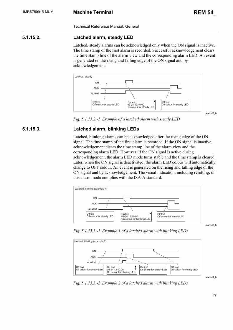
1MRS750915-MUM REM 54_
77
Machine Terminal Technical Reference Manual, General
5.1.15.2. Latched alarm, steady LEDLatched, steady alarms can be acknowledged only when the ON signal is inactive. The time stamp of the first alarm is recorded. Successful acknowledgement clears the time stamp line of the alarm view and the corresponding alarm LED. An event is generated on the rising and falling edge of the ON signal and by acknowledgement.
alarind3_b
Fig. 5.1.15.2.-1 Example of a latched alarm with steady LED
5.1.15.3. Latched alarm, blinking LEDsLatched, blinking alarms can be acknowledged after the rising edge of the ON signal. The time stamp of the first alarm is recorded. If the ON signal is inactive, acknowledgement clears the time stamp line of the alarm view and the corresponding alarm LED. However, if the ON signal is active during acknowledgement, the alarm LED mode turns stable and the time stamp is cleared. Later, when the ON signal is deactivated, the alarm LED colour will automatically change to OFF colour. An event is generated on the rising and falling edge of the ON signal and by acknowledgement. The visual indication, including resetting, of this alarm mode complies with the ISA-A standard.
alarind2_b
Fig. 5.1.15.3.-1 Example 1 of a latched alarm with blinking LEDs
alarind1_b
Fig. 5.1.15.3.-2 Example 2 of a latched alarm with blinking LEDs
�<<�%.8%�<<�:�4�70�<�0��%.23E����
�/�%.8%�+1�*���J*�J���/�:�4�70�<�0��%.23E����
�<<�%.8%�<<�:�4�70�<�0��%.23E����
��A
��
���6
�2%:!.3,��%.23E
��A
��
���6
�<<�%.8%�<<�:�4�70�<�0��%.23E����
�/�%.8%�+1�*���J*�J���/�:�4�70�<�0�G4�/@�/ ����
�<<�%.8%�<<�:�4�70�<�0��%.23E����
�2%:!.3,�G4�/@�/ �>.825D4.��?
��A
��
���6
�<<�%.8%�<<�:�4�70�<�0��%.23E����
�/�%.8%�+1�*���J*�J���/�:�4�70�<�0�G4�/@�/ ����
�/�%.8%�/�:�4�70�<�0��%.23E����
�<<�%.8%�<<�:�4�70�<�0��%.23E����
�2%:!.3,�G4�/@�/ �>.825D4.��?
78
1MRS750915-MUMMachine Terminal Technical Reference Manual, General
REM 54_
5.1.15.4. InterlockingThe interlocking LED text can be defined in the same manner as for the other alarm channels. The colour of the interlocking LED is yellow and cannot be changed. The normal LED state is inactive (no light). Furthermore, the interlocking LED has two special modes. The first mode, recognized by a steady yellow light, indicates that control operation has been interlocked. The second mode, recognized by a blinking red light, indicates that the interlocking is in bypass mode (control test mode).
General control test modeThe system provides a general interlocking bypass mode (Main menu/Control/Interl bypass) that overrides all interlocking signals. Activation of the interlocking bypass mode activates the interlocking enable signals of all control objects. Thus, all local control actions are possible and the enable signals (OPENENA, CLOSEENA) of controllable objects are not checked while the objects are commanded. As long as the mode is active, the interlocking LED on the HMI is blinking red. Additionally, the assisting window of the display will indicate the special condition.
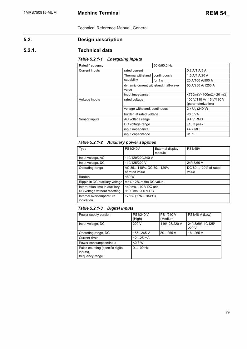
1MRS750915-MUM REM 54_
79
Machine Terminal Technical Reference Manual, General
5.2. Design description
5.2.1. Technical data Table 5.2.1-1 Energizing inputsRated frequency 50.0/60.0 HzCurrent inputs rated current 0.2 A/1 A/5 A
Thermal withstand capability
continuously 1.5 A/4 A/20 Afor 1 s 20 A/100 A/500 A
dynamic current withstand, half-wave value
50 A/250 A/1250 A
input impedance <750m/<100m<20 mVoltage inputs rated voltage 100 V/110 V/115 V/120 V
(parameterization)voltage withstand, continuous 2 x Un (240 V)
burden at rated voltage <0.5 VASensor inputs AC voltage range 9.4 V RMS
DC voltage range ±13.3 peakinput impedance >4.7 Minput capacitance <1 nF
Table 5.2.1-2 Auxiliary power suppliesType PS1/240V External display
modulePS1/48V
Input voltage, AC 110/120/220/240 V -Input voltage, DC 110/125/220 V 24/48/60 VOperating range AC 85…110%, DC 80…120%
of rated valueDC 80…120% of rated value
Burden <50 WRipple in DC auxiliary voltage max. 12% of the DC valueInterruption time in auxiliary DC voltage without resetting
<40 ms, 110 V DC and <100 ms, 200 V DC
Internal overtemperature indication
+78C (+75…+83C)
Table 5.2.1-3 Digital inputsPower supply version PS1/240 V
(High)PS1/240 V (Medium)
PS1/48 V (Low)
Input voltage, DC 220 V 110/125/220 V 24/48/60/110/125/220 V
Operating range, DC 155...265 V 80…265 V 18...265 VCurrent drain ~2…25 mAPower consumption/input <0.8 WPulse counting (specific digital inputs), frequency range
0…100 Hz
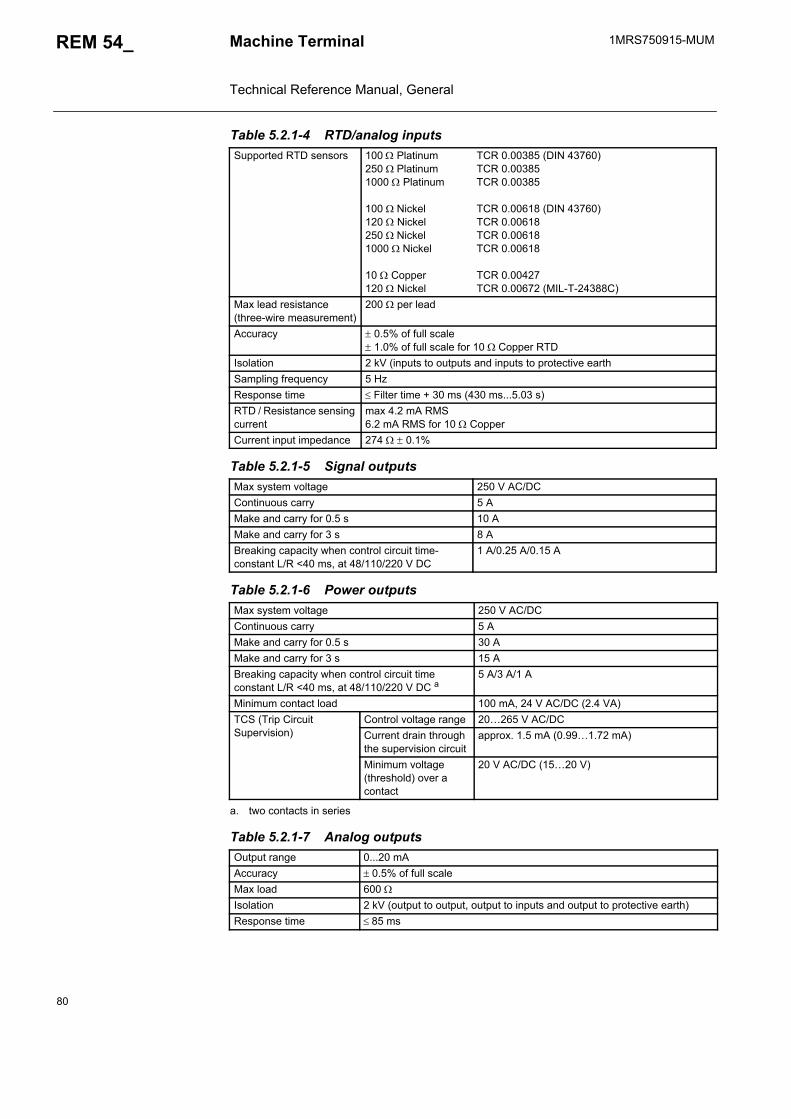
80
1MRS750915-MUMMachine Terminal Technical Reference Manual, General
REM 54_
Table 5.2.1-4 RTD/analog inputs Supported RTD sensors 100 Platinum
250 Platinum 1000 Platinum
100 Nickel 120 Nickel 250 Nickel1000 Nickel
10 Copper 120 Nickel
TCR 0.00385 (DIN 43760)TCR 0.00385TCR 0.00385
TCR 0.00618 (DIN 43760)TCR 0.00618TCR 0.00618TCR 0.00618
TCR 0.00427TCR 0.00672 (MIL-T-24388C)
Max lead resistance (three-wire measurement)
200 per lead
Accuracy 0.5% of full scale 1.0% of full scale for 10 Copper RTD
Isolation 2 kV (inputs to outputs and inputs to protective earthSampling frequency 5 HzResponse time Filter time + 30 ms (430 ms...5.03 s)RTD / Resistance sensing current
max 4.2 mA RMS6.2 mA RMS for 10 Copper
Current input impedance 274 0.1%
Table 5.2.1-5 Signal outputsMax system voltage 250 V AC/DCContinuous carry 5 AMake and carry for 0.5 s 10 AMake and carry for 3 s 8 ABreaking capacity when control circuit time-constant L/R <40 ms, at 48/110/220 V DC
1 A/0.25 A/0.15 A
Table 5.2.1-6 Power outputsMax system voltage 250 V AC/DCContinuous carry 5 AMake and carry for 0.5 s 30 AMake and carry for 3 s 15 ABreaking capacity when control circuit time constant L/R <40 ms, at 48/110/220 V DC a
a. two contacts in series
5 A/3 A/1 A
Minimum contact load 100 mA, 24 V AC/DC (2.4 VA)TCS (Trip Circuit Supervision)
Control voltage range 20…265 V AC/DCCurrent drain through the supervision circuit
approx. 1.5 mA (0.99…1.72 mA)
Minimum voltage (threshold) over a contact
20 V AC/DC (15…20 V)
Table 5.2.1-7 Analog outputsOutput range 0...20 mAAccuracy 0.5% of full scaleMax load 600 Isolation 2 kV (output to output, output to inputs and output to protective earth)Response time 85 ms

1MRS750915-MUM REM 54_
81
Machine Terminal Technical Reference Manual, General
Table 5.2.1-8 Environmental conditionsSpecified service temperature range -10…+55CTransport and storage temperature range -40…+70CEnclosure class front side, flush-mounted IP 54
rear side, connection terminals IP 20Dry heat test according to IEC 60068-2-2Dry cold test according to IEC 60068-2-1Damp heat test, cyclic according to IEC 60068-2-30,
r.h. = 95%, T = 25…55CStorage temperature tests according to IEC 60068-2-48
Table 5.2.1-9 Standard testsInsulation tests Dielectric test
IEC 60255-5Test voltage 2 kV, 50 Hz, 1 min.
Impulse voltage testIEC 60255-5
Test voltage 5 kV, unipolar impulses, waveform 1,2/50 s, source energy 0.5 J
Insulation resistance measurementsIEC 60255-5
Insulation resistance
> 100 M, 500 V DC
Mechanical tests Vibration tests (sinusoidal) IEC 60255-21-1, class IShock and bump test IEC 60255-21-2, class ISeismic tests IEC 60255-21-3, class 2
Table 5.2.1-10 Electromagnetic compatibility tests The EMC immunity test level fulfills the requirements listed below1 MHz burst disturbance test, class III, IEC 60255-22-1
common mode 2.5 kVdifferential mode 1.0 kV
Electrostatic discharge test,class IIIIEC 61000-4-2 and 60255-22-2
for contact discharge 6 kVfor air discharge 8 kV
Radio frequency interference test
conducted, common modeIEC 61000-4-6
10 V (rms), f = 150 kHz…80 MHz
radiated, amplitude-modulatedIEC 61000-4-3
10 V/m (rms),f = 80…1000 MHz
radiated, pulse-modulatedENV 50204
10 V/m, f = 900 MHz
radiated, test with a portable transmitterIEC 60255-22-3, method C
f = 77.2 MHz, P = 6 W;f = 172.25 MHz, P = 5 W
Fast transient disturbance testIEC 60255-22-4 and IEC 61000-4-4
power supply 4 kV
I/O ports 2 kVSurge immunity testIEC 61000-4-5
power supply 4 kV, common mode2 kV, differential mode
I/O ports 2 kV, common mode1 kV, differential mode
Power frequency (50 Hz)magnetic fieldIEC 61000-4-8
100 A/m
Voltage dips andshort interruptionsIEC 61000-4-11
30%, 10 ms60%, 100 ms60%, 1000 ms>90%, 5000 ms
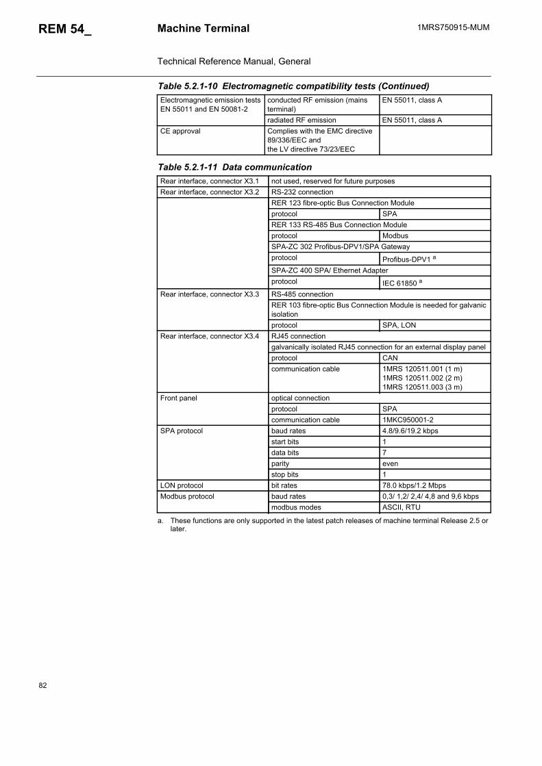
82
1MRS750915-MUMMachine Terminal Technical Reference Manual, General
REM 54_
Electromagnetic emission testsEN 55011 and EN 50081-2
conducted RF emission (mains terminal)
EN 55011, class A
radiated RF emission EN 55011, class ACE approval Complies with the EMC directive
89/336/EEC and the LV directive 73/23/EEC
Table 5.2.1-11 Data communicationRear interface, connector X3.1 not used, reserved for future purposesRear interface, connector X3.2 RS-232 connection
RER 123 fibre-optic Bus Connection Moduleprotocol SPARER 133 RS-485 Bus Connection Moduleprotocol ModbusSPA-ZC 302 Profibus-DPV1/SPA Gateway protocol Profibus-DPV1 a
SPA-ZC 400 SPA/ Ethernet Adapter protocol IEC 61850 a
Rear interface, connector X3.3 RS-485 connectionRER 103 fibre-optic Bus Connection Module is needed for galvanic isolationprotocol SPA, LON
Rear interface, connector X3.4 RJ45 connectiongalvanically isolated RJ45 connection for an external display panelprotocol CANcommunication cable 1MRS 120511.001 (1 m)
1MRS 120511.002 (2 m)1MRS 120511.003 (3 m)
Front panel optical connectionprotocol SPAcommunication cable 1MKC950001-2
SPA protocol baud rates 4.8/9.6/19.2 kbpsstart bits 1data bits 7parity evenstop bits 1
LON protocol bit rates 78.0 kbps/1.2 MbpsModbus protocol baud rates 0,3/ 1,2/ 2,4/ 4,8 and 9,6 kbps
modbus modes ASCII, RTU
a. These functions are only supported in the latest patch releases of machine terminal Release 2.5 or later.
Table 5.2.1-10 Electromagnetic compatibility tests (Continued)

1MRS750915-MUM REM 54_
83
Machine Terminal Technical Reference Manual, General
Table 5.2.1-12 GeneralToolboxes CAP 501
CAP 505LNT 505
Event recording all events are recorded in higher level syntax: reason, time, datethe last 100 events are recorded
Data recording records operate valuesProtection functionsControl functionsCondition monitoring functionsMeasurement functionsCommunication functions
see Technical Descriptions of Functions(1MRS 750889-MCD)
Self-supervision RAM circuitsROM circuitsParameter memory circuitsCPU watchdogPower supplyDigital I/O modulesHMI moduleRTD/analog input moduleInternal communication busA/D converters and analog multiplexers
Mechanical dimensions Width: 223.7 mm (1/2 of a 19” rack)Height, frame: 265.9 mm (6U)Height, box: 249.8 mmDepth: 235 mmFor dimension drawings, refer to the Installation Manual (1MRS 750526-MUM)External display module:
Width: 223.7 mmHeight: 265.9 mmDepth: 74 mm
Weight of the unit ~8 kg

84
1MRS750915-MUMMachine Terminal Technical Reference Manual, General
REM 54_
5.2.2. Terminal diagram of REM 543
A060273
Fig. 5.2.2.-1 Terminal diagram of REM 543
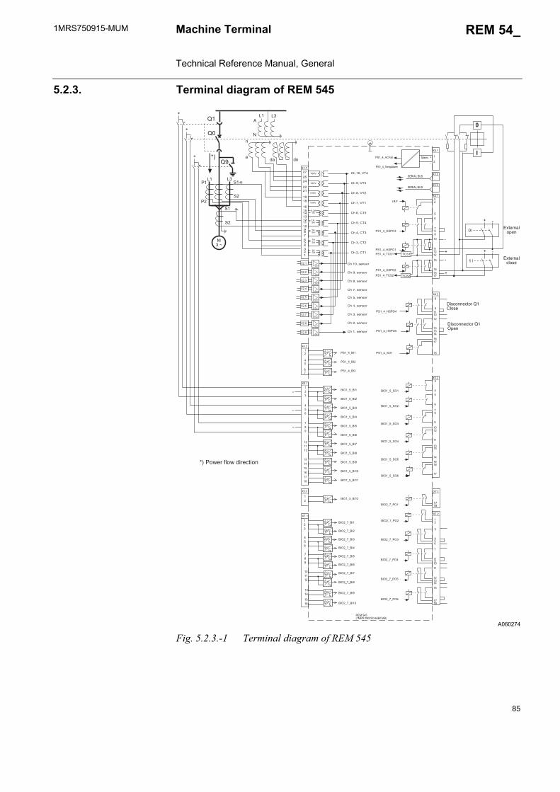
1MRS750915-MUM REM 54_
85
Machine Terminal Technical Reference Manual, General
5.2.3. Terminal diagram of REM 545
A060274
Fig. 5.2.3.-1 Terminal diagram of REM 545
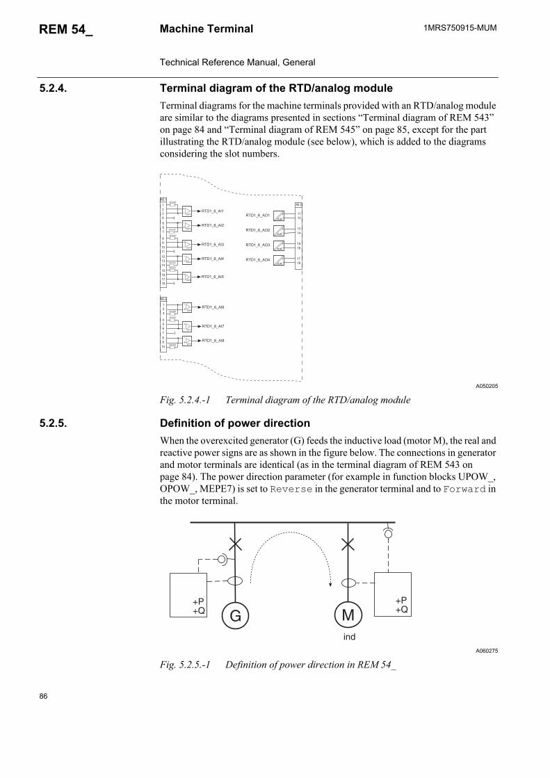
86
1MRS750915-MUMMachine Terminal Technical Reference Manual, General
REM 54_
5.2.4. Terminal diagram of the RTD/analog moduleTerminal diagrams for the machine terminals provided with an RTD/analog module are similar to the diagrams presented in sections “Terminal diagram of REM 543” on page 84 and “Terminal diagram of REM 545” on page 85, except for the part illustrating the RTD/analog module (see below), which is added to the diagrams considering the slot numbers.
A050205
Fig. 5.2.4.-1 Terminal diagram of the RTD/analog module
5.2.5. Definition of power directionWhen the overexcited generator (G) feeds the inductive load (motor M), the real and reactive power signs are as shown in the figure below. The connections in generator and motor terminals are identical (as in the terminal diagram of REM 543 on page 84). The power direction parameter (for example in function blocks UPOW_, OPOW_, MEPE7) is set to Reverse in the generator terminal and to Forward in the motor terminal.
A060275
Fig. 5.2.5.-1 Definition of power direction in REM 54_
? 3��&
')'@
')'@
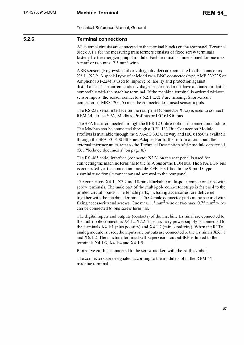
1MRS750915-MUM REM 54_
87
Machine Terminal Technical Reference Manual, General
5.2.6. Terminal connectionsAll external circuits are connected to the terminal blocks on the rear panel. Terminal block X1.1 for the measuring transformers consists of fixed screw terminals fastened to the energizing input module. Each terminal is dimensioned for one max. 6 mm2 or two max. 2.5 mm2 wires.
ABB sensors (Rogowski coil or voltage divider) are connected to the connectors X2.1...X2.9. A special type of shielded twin BNC connector (type AMP 332225 or Amphenol 31-224) is used to improve reliability and protection against disturbances. The current and/or voltage sensor used must have a connector that is compatible with the machine terminal. If the machine terminal is ordered without sensor inputs, the sensor connectors X2.1...X2.9 are missing. Short-circuit connectors (1MRS120515) must be connected to unused sensor inputs.
The RS-232 serial interface on the rear panel (connector X3.2) is used to connect REM 54_ to the SPA, Modbus, Profibus or IEC 61850 bus.
The SPA bus is connected through the RER 123 fibre-optic bus connection module. The Modbus can be connected through a RER 133 Bus Connection Module. Profibus is available through the SPA-ZC 302 Gateway and IEC 61850 is available through the SPA-ZC 400 Ethernet Adapter.For further information, about the external interface units, refer to the Technical Description of the module concerned. (See “Related documents” on page 8.)
The RS-485 serial interface (connector X3.3) on the rear panel is used for connecting the machine terminal to the SPA bus or the LON bus. The SPA/LON bus is connected via the connection module RER 103 fitted to the 9-pin D-type subminiature female connector and screwed to the rear panel.
The connectors X4.1...X7.2 are 18-pin detachable multi-pole connector strips with screw terminals. The male part of the multi-pole connector strips is fastened to the printed circuit boards. The female parts, including accessories, are delivered together with the machine terminal. The female connector part can be secured with fixing accessories and screws. One max. 1.5 mm2 wire or two max. 0.75 mm2 wires can be connected to one screw terminal.
The digital inputs and outputs (contacts) of the machine terminal are connected to the multi-pole connectors X4.1...X7.2. The auxiliary power supply is connected to the terminals X4.1:1 (plus polarity) and X4.1:2 (minus polarity). When the RTD/analog module is used, the inputs and outputs are connected to the terminals X6.1:1 and X6.1:2. The machine terminal self-supervision output IRF is linked to the terminals X4.1:3, X4.1:4 and X4.1:5.
Protective earth is connected to the screw marked with the earth symbol.
The connectors are designated according to the module slot in the REM 54_ machine terminal.

88
1MRS750915-MUMMachine Terminal Technical Reference Manual, General
REM 54_
A060276
Fig. 5.2.6.-1 Rear views of REM 543 (right: with RTD/analog module)
Table 5.2.6-1 REM 54_ terminal connections
Connector DescriptionX1.1 connector for transformer inputs (current and voltage transformers)
(module slot 1)X2.1 connector for sensor input 9 (slot 2)X2.2 connector for sensor input 8 (slot 2)X2.3 connector for sensor input 7 (slot 2)X2.4 connector for sensor input 6 (slot 2)X2.5 connector for sensor input 5 (slot 2)X2.6 connector for sensor input 4 (slot 2)X2.7 connector for sensor input 3 (slot 2)X2.8 connector for sensor input 2 (slot 2)X2.9 connector for sensor input 1 (slot 2)X3.1 not used, reserved for future purposes (slot 3)X3.2 connector for RS-232 interface (slot 3)X3.3 connector for RS-485 interface (slot 3)X3.4 connector for the external display module (slot 2)X4.1 upper connector for combined I/O and power supply module PS1 (slot 4)X4.2 lower connector for combined I/O and power supply module PS1 (slot 4) X5.1 upper connector for I/O module BIO1 (slot 5) X5.2 lower connector for I/O module BIO1 (slot 5) X6.1 upper connector for I/O module BIO1 (slot 6), REM 543
upper connector for RTD/analog module (slot 6), REM 543 or REM 545 with RTD/analog module
X6.2 lower connector for I/O module BIO1 (slot 6), REM 543lower connector for RTD/analog module (slot 6), REM 543 or REM 545 with RTD/analog module
X7.1 upper connector for I/O module BIO2 (slot 7) X7.2 lower connector for I/O module BIO2 (slot 7)
���
�$�
� ,�$
� ,
-02/�<05
����
6-��
���
�$�
� ,�$
� ,
-02/�<05
����
��*'��)+��������*�'�����)
��*'��)+��������*�'�����)
��*'��)+��������*�'�����)
��*'��)+��������*�'�����)
��
��
�'
�*
�
��
��
��
�+
�)
��
��
�'
�*
�
��
��
��
+
)
�
�
'
*
�
�
&�(� &�(� &'(�
&�(�
&*(� &�(�
&�(� &'(� &*(�
��*'��)+��������*�'�����)
&(�
&(�
&(
��*'��)+��������*�'�����)
��*'��)+��������*�'�����)
&(*
23.��/���/42/3
&�(���
&�(���
&�(��
&�(*��
&�('��
&�(���
&�(���
&�()��
&�(+��
��
6� '*�C������;����
��*'��)+��������*�'�����)
��*'��)+��������*�'�����)
��*'��)+��������*�'�����)
��*'��)+��������*�'�����)
��*'��)+��������*�'�����)
��
��
�'
�*
�
��
��
��
�+
�)
��
��
�'
�*
�
��
��
��
+
)
�
�
'
*
�
�
&�(� &�(� &'(�
&�(�
&*(� &�(�
&�(� &'(� &*(�
��*'��)+��������*�'�����)
&(�
&(�
&(
&(*
23.��/���/42/3
&�(���
&�(���
&�(��
&�(*��
&�('��
&�(���
&�(���
&�()��
&�(+��
��
6� '*�C�������;����
��*'��)+��������*�'�����)
��*'��)+��������*�'�����)
��*'��)+��������*�'�����)

1MRS750915-MUM REM 54_
89
Machine Terminal Technical Reference Manual, General
A060277
Fig. 5.2.6.-2 Rear views of REM 545 (right: with RTD/analog module)
A060278A060280
Fig. 5.2.6.-3 Rear view of REM 545 with an external display module (right: the external display module)
����
���
�$�
� ,�$
� ,
-02/�<05
����
6-��
����
���
�$�
� ,�$
� ,
-02/�<05
����
��*'��)+��������*�'�����)
��*'��)+��������*�'�����)
��*'��)+��������*�'�����)
��*'��)+��������*�'�����)
��
��
�'
�*
�
��
��
��
�+
�)
��
��
�'
�*
�
��
��
��
+
)
�
�
'
*
�
�
&�(� &�(� &'(�
&�(�
&*(� &�(�
&�(� &'(� &*(�
��*'��)+��������*�'�����)
��*'��)+��������*�'�����)
&(�
&(�
&(
��*'��)+��������*�'�����)
��*'��)+��������*�'�����)
&(*
23.��/���/42/3
&�(���
&�(���
&�(��
&�(*��
&�('��
&�(���
&�(���
&�()��
&�(+��
��
6� '*'�C������;����
��*'��)+��������*�'�����)
��*'��)+��������*�'�����)
��*'��)+��������*�'�����)
��*'��)+��������*�'�����)
��
��
�'
�*
�
��
��
��
�+
�)
��
��
�'
�*
�
��
��
��
+
)
�
�
'
*
�
�
&�(� &�(� &'(�
&�(�
&*(� &�(�
&�(� &'(� &*(�
��*'��)+��������*�'�����)
��*'��)+��������*�'�����)
&(�
&(�
&(
&(*
23.��/���/42/3
&�(���
&�(���
&�(��
&�(*��
&�('��
&�(���
&�(���
&�()��
&�(+��
��
6� '*'�C�������;����
��*'��)+��������*�'�����)
��*'��)+��������*�'�����)
����
���
�$�
� ,�$
� ,
-02/�<05
����
6-��
��*'��)+��������*�'�����)
��*'��)+��������*�'�����)
��*'��)+��������*�'�����)
��*'��)+��������*�'�����)
��
��
�'
�*
�
��
��
��
�+
�)
��
��
�'
�*
�
��
��
��
+
)
�
�
'
*
�
�
&�(� &�(� &'(�
&�(�
&*(� &�(�
&�(� &'(� &*(�
��*'��)+��������*�'�����)
��*'��)+��������*�'�����)
&(�
&(�
&(
��*'��)+��������*�'�����)
��*'��)+��������*�'�����)
&(*
23.��/���/42/3
&�(���
&�(���
&�(��
&�(*��
&�('��
&�(���
&�(���
&�()��
&�(+��
��
6� '*'�C������
90
1MRS750915-MUMMachine Terminal Technical Reference Manual, General
REM 54_
6. Service
When the machine terminal is used under the conditions specified in Section 5.2.1. Technical data, it is practically maintenance-free. The machine terminal electronics include no parts or components subject to abnormal physical or electrical wear under normal operating conditions.
If the terminal fails in operation or if the operating values considerably differ from those mentioned in the machine terminal specifications, the terminal should be overhauled. Only personnel authorized by the manufacturer is allowed to carry out repairs. Please contact the manufacturer or the nearest representative for further information about checking, overhaul and recalibration of the terminal.
To achieve the best possible operation accuracy, all parts of the machine terminal have been calibrated together. In the event of malfunction, please consult your supplier.
If the protection relay is sent to the manufacturer, it has to be carefully packed to prevent further damage to the device.
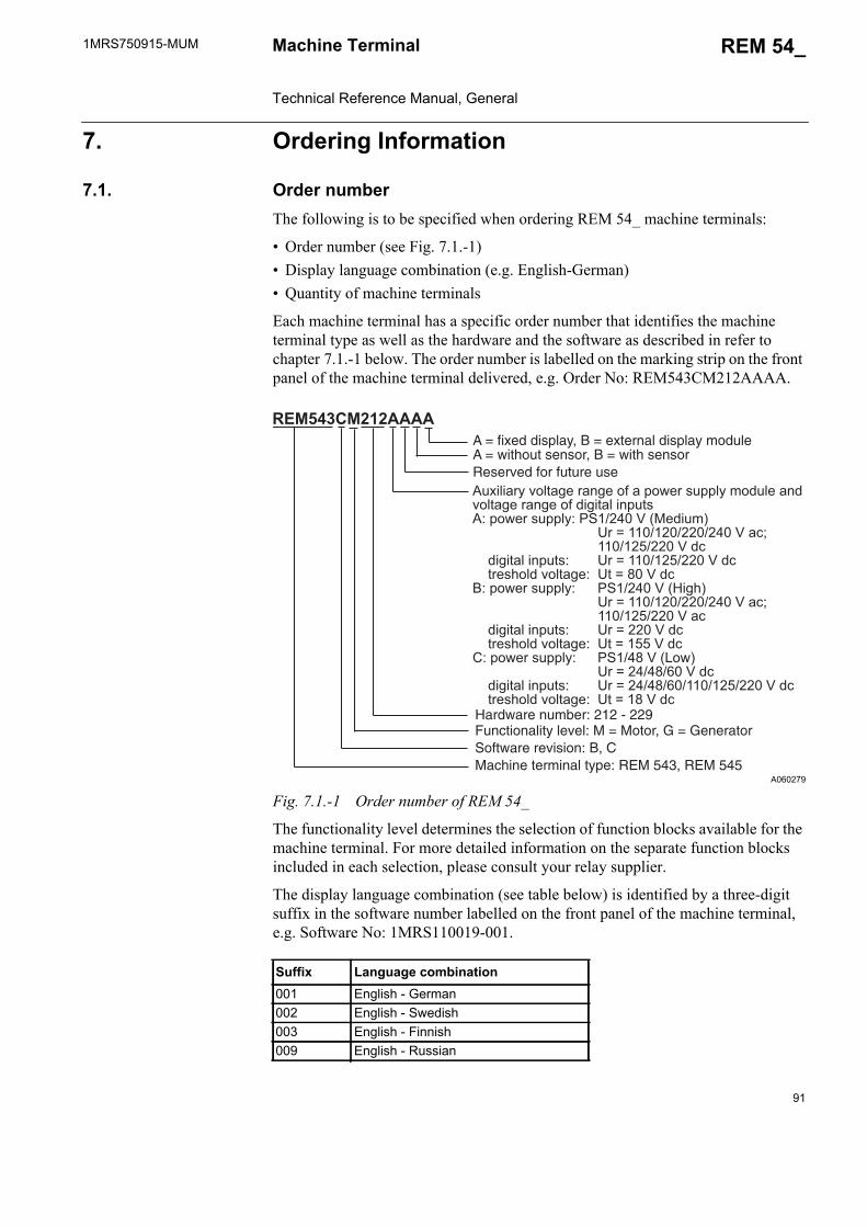
1MRS750915-MUM REM 54_
91
Machine Terminal Technical Reference Manual, General
7. Ordering Information
7.1. Order numberThe following is to be specified when ordering REM 54_ machine terminals:
• Order number (see Fig. 7.1.-1)• Display language combination (e.g. English-German)• Quantity of machine terminals
Each machine terminal has a specific order number that identifies the machine terminal type as well as the hardware and the software as described in refer to chapter 7.1.-1 below. The order number is labelled on the marking strip on the front panel of the machine terminal delivered, e.g. Order No: REM543CM212AAAA.
A060279
Fig. 7.1.-1 Order number of REM 54_
The functionality level determines the selection of function blocks available for the machine terminal. For more detailed information on the separate function blocks included in each selection, please consult your relay supplier.
The display language combination (see table below) is identified by a three-digit suffix in the software number labelled on the front panel of the machine terminal, e.g. Software No: 1MRS110019-001.
Suffix Language combination001 English - German002 English - Swedish003 English - Finnish009 English - Russian
Auxiliary voltage range of a power supply module andvoltage range of digital inputsA: power supply: PS1/240 V (Medium) Ur = 110/120/220/240 V ac; 110/125/220 V dc digital inputs: Ur = 110/125/220 V dc treshold voltage: Ut = 80 V dcB: power supply: PS1/240 V (High) Ur = 110/120/220/240 V ac; 110/125/220 V ac digital inputs: Ur = 220 V dc treshold voltage: Ut = 155 V dcC: power supply: PS1/48 V (Low) Ur = 24/48/60 V dc digital inputs: Ur = 24/48/60/110/125/220 V dc treshold voltage: Ut = 18 V dc
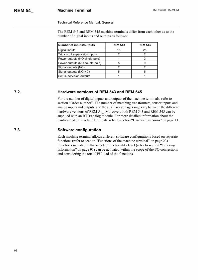
92
1MRS750915-MUMMachine Terminal Technical Reference Manual, General
REM 54_
The REM 543 and REM 545 machine terminals differ from each other as to the number of digital inputs and outputs as follows:
7.2. Hardware versions of REM 543 and REM 545For the number of digital inputs and outputs of the machine terminals, refer to section “Order number”. The number of matching transformers, sensor inputs and analog inputs and outputs, and the auxiliary voltage range vary between the different hardware versions of REM 54_. Moreover, both REM 543 and REM 545 can be supplied with an RTD/analog module. For more detailed information about the hardware of the machine terminals, refer to section “Hardware versions” on page 11.
7.3. Software configurationEach machine terminal allows different software configurations based on separate functions (refer to section “Functions of the machine terminal” on page 23). Functions included in the selected functionality level (refer to section “Ordering Information” on page 91) can be activated within the scope of the I/O connections and considering the total CPU load of the functions.
Number of inputs/outputs REM 543 REM 545Digital inputs 15 25Trip circuit supervision inputs 2 2Power outputs (NO single-pole) - 2Power outputs (NO double-pole) 5 9Signal outputs (NO) 2 2Signal outputs (NO/NC) 5 5Self-supervision outputs 1 1
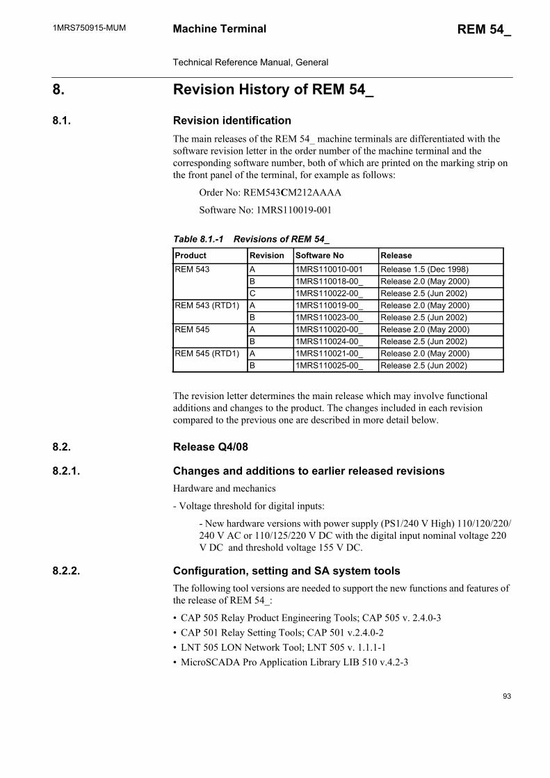
1MRS750915-MUM REM 54_
93
Machine Terminal Technical Reference Manual, General
8. Revision History of REM 54_
8.1. Revision identificationThe main releases of the REM 54_ machine terminals are differentiated with the software revision letter in the order number of the machine terminal and the corresponding software number, both of which are printed on the marking strip on the front panel of the terminal, for example as follows:
Order No: REM543CM212AAAA
Software No: 1MRS110019-001
The revision letter determines the main release which may involve functional additions and changes to the product. The changes included in each revision compared to the previous one are described in more detail below.
8.2. Release Q4/08
8.2.1. Changes and additions to earlier released revisionsHardware and mechanics
- Voltage threshold for digital inputs:
- New hardware versions with power supply (PS1/240 V High) 110/120/220/240 V AC or 110/125/220 V DC with the digital input nominal voltage 220 V DC and threshold voltage 155 V DC.
8.2.2. Configuration, setting and SA system toolsThe following tool versions are needed to support the new functions and features of the release of REM 54_:
• CAP 505 Relay Product Engineering Tools; CAP 505 v. 2.4.0-3• CAP 501 Relay Setting Tools; CAP 501 v.2.4.0-2• LNT 505 LON Network Tool; LNT 505 v. 1.1.1-1• MicroSCADA Pro Application Library LIB 510 v.4.2-3
Table 8.1.-1 Revisions of REM 54_
Product Revision Software No ReleaseREM 543 A 1MRS110010-001 Release 1.5 (Dec 1998)
B 1MRS110018-00_ Release 2.0 (May 2000)C 1MRS110022-00_ Release 2.5 (Jun 2002)
REM 543 (RTD1) A 1MRS110019-00_ Release 2.0 (May 2000)B 1MRS110023-00_ Release 2.5 (Jun 2002)
REM 545 A 1MRS110020-00_ Release 2.0 (May 2000)B 1MRS110024-00_ Release 2.5 (Jun 2002)
REM 545 (RTD1) A 1MRS110021-00_ Release 2.0 (May 2000)B 1MRS110025-00_ Release 2.5 (Jun 2002)
94
1MRS750915-MUMMachine Terminal Technical Reference Manual, General
REM 54_
• REM 543/545 Connectivity package v.2.2• Communication Engineering Tool for COM610, SPA-ZC 40x or MicroSCADA
Pro SYS 600 and COM 500• SCL Importer in MicroSCADA Pro SYS 600 and COM 500
8.3. Patch release, SW build 4.00
8.3.1. Changes and additions to earlier released revisionsProtocols & communication
• Faster communication with SPA-ZC 302• Faster communication with SPA-ZC 400 with limited GOOSE messages
8.3.2. Configuration, setting and SA system toolsThe following tool versions are needed to support the new functions and features of patch release of REM 54_:
• CAP 505 Relay Product Engineering Tools; CAP 505 v. 2.4.0-2• CAP 501 Relay Setting Tools; CAP 501 v. 2.4.0-2• LNT 505 LON Network Tool; LNT 505 v. 1.1.1-1• MicroSCADA Pro Application Library LIB 510 v. 4.2-3• REM 543/545 Connectivity package v. 2.2• Communication Engineering Tool for COM610, SPA-ZC 40x or MicroSCADA
Pro SYS 600 and COM 500• SCL Importer in MicroSCADA Pro SYS 600 and COM 500
8.4. Release 2.5
8.4.1. Changes and additions to earlier released revisionsGeneral
• Filtering times of digital inputs• New type of RTD input: Ni 120US• Technical data corrections
Function blocks
• Modification of Diff3, the high-impedance or flux-balance based differential protection function block• adjustable time setting added
• NOC3Low and NEF1Low: addition of ANSI inverse time curve
For further information about the changes above, refer to the function block descriptions on the CD-ROM Technical Descriptions of Functions.
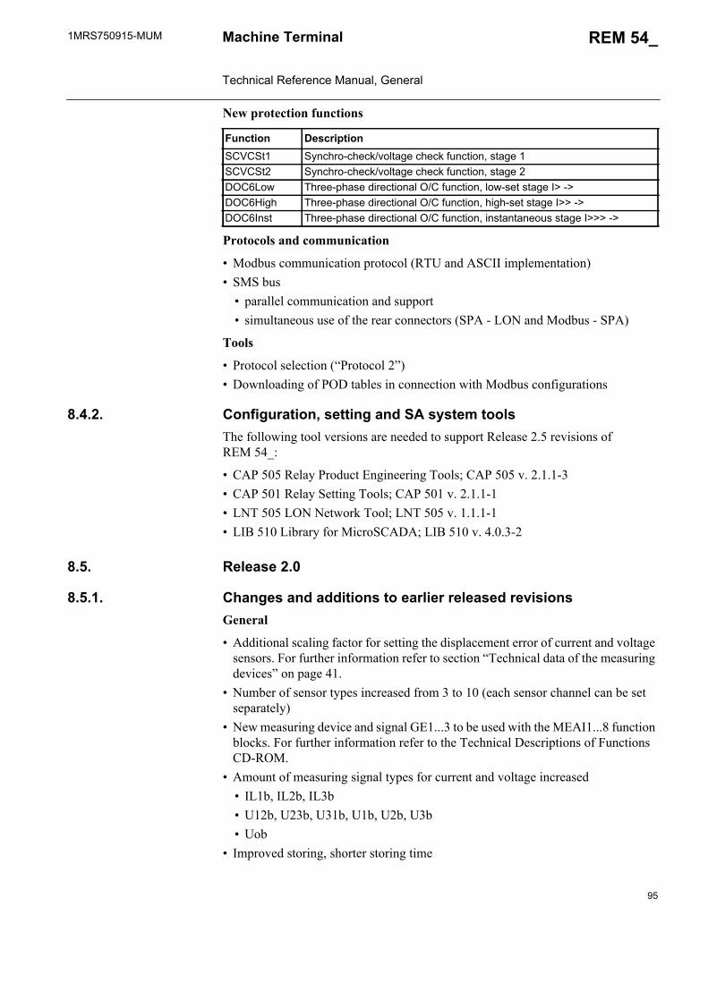
1MRS750915-MUM REM 54_
95
Machine Terminal Technical Reference Manual, General
New protection functions
Protocols and communication
• Modbus communication protocol (RTU and ASCII implementation) • SMS bus
• parallel communication and support• simultaneous use of the rear connectors (SPA - LON and Modbus - SPA)
Tools
• Protocol selection (“Protocol 2”)• Downloading of POD tables in connection with Modbus configurations
8.4.2. Configuration, setting and SA system toolsThe following tool versions are needed to support Release 2.5 revisions of REM 54_:
• CAP 505 Relay Product Engineering Tools; CAP 505 v. 2.1.1-3 • CAP 501 Relay Setting Tools; CAP 501 v. 2.1.1-1• LNT 505 LON Network Tool; LNT 505 v. 1.1.1-1• LIB 510 Library for MicroSCADA; LIB 510 v. 4.0.3-2
8.5. Release 2.0
8.5.1. Changes and additions to earlier released revisionsGeneral
• Additional scaling factor for setting the displacement error of current and voltage sensors. For further information refer to section “Technical data of the measuring devices” on page 41.
• Number of sensor types increased from 3 to 10 (each sensor channel can be set separately)
• New measuring device and signal GE1...3 to be used with the MEAI1...8 function blocks. For further information refer to the Technical Descriptions of Functions CD-ROM.
• Amount of measuring signal types for current and voltage increased• IL1b, IL2b, IL3b• U12b, U23b, U31b, U1b, U2b, U3b• Uob
• Improved storing, shorter storing time
Function DescriptionSCVCSt1 Synchro-check/voltage check function, stage 1SCVCSt2 Synchro-check/voltage check function, stage 2DOC6Low Three-phase directional O/C function, low-set stage I> ->DOC6High Three-phase directional O/C function, high-set stage I>> ->DOC6Inst Three-phase directional O/C function, instantaneous stage I>>> ->

96
1MRS750915-MUMMachine Terminal Technical Reference Manual, General
REM 54_
• New language versions:• English - Swedish• English - Finnish
• An informative parameter, Config. capacity, added (Main menu/Configuration/General/Config. capacity). For further information refer to the Configuration Guideline (1MRS750745-MUM).
• Menu descriptions of virtual I/Os changed to match the names in tools• 48-hour capacitor back-up for the internal clock of the machine terminal• Selection of latching feature for the Start LED can be stored in the non-volatile
memory
Function blocks
• Function block revision added (uploading of the function block list to CAP 505)• Measurement function blocks: outputs indicating the status of warning and alarm
limits added• Under- and overvoltage protection function blocks UV3_ and OV3_:
• phase-selective start outputs added• control setting parameter Oper. hysteresis added for adjusting the level
of a comparator (for more information, refer to the CD-ROM Technical Descriptions of Functions)
• EVENT230 function block: input interface changed• Changes to input names in the following function blocks: UV3Low, UV3High,
OV3Low, OV3High, MEVO3A, CMVO3• MEPE7, the function block for power and energy measurement:
• Events for energy (E), apparent power (S), and cos added• Time-based delta event sending added
• Start time range of the MotStart function block changed from 0.3...80.0 s to 0.3... 250 s
For further information about the above changes, refer to the function block descriptions on the CD-ROM Technical Descriptions of Functions.
New protection functions
Function DescriptionDiff3 High-impedance or flux-balance based differential protection for
generators and motorsFuseFail Fuse failure supervisionPREV3 Phase reversal protectionPSV3St1 Phase-sequence voltage protection, stage 1PSV3St2 Phase-sequence voltage protection, stage 2UI6Low Three-phase underimpedance protection, low-set stageUI6High Three-phase underimpedance protection, high-set stageOE1Low Overexcitation protection, low-set stageOE1High Overexcitation protection, high-set stage
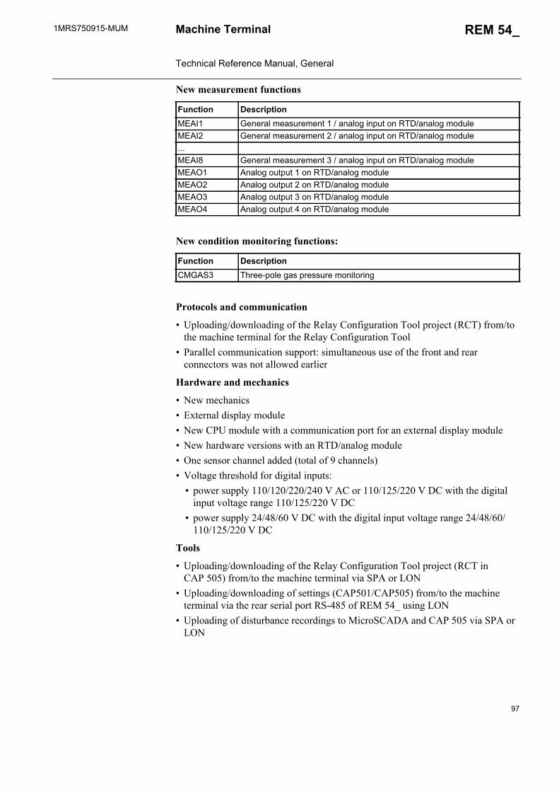
1MRS750915-MUM REM 54_
97
Machine Terminal Technical Reference Manual, General
New measurement functions
New condition monitoring functions:
Protocols and communication
• Uploading/downloading of the Relay Configuration Tool project (RCT) from/to the machine terminal for the Relay Configuration Tool
• Parallel communication support: simultaneous use of the front and rear connectors was not allowed earlier
Hardware and mechanics
• New mechanics• External display module• New CPU module with a communication port for an external display module• New hardware versions with an RTD/analog module• One sensor channel added (total of 9 channels)• Voltage threshold for digital inputs:
• power supply 110/120/220/240 V AC or 110/125/220 V DC with the digital input voltage range 110/125/220 V DC
• power supply 24/48/60 V DC with the digital input voltage range 24/48/60/110/125/220 V DC
Tools
• Uploading/downloading of the Relay Configuration Tool project (RCT in CAP 505) from/to the machine terminal via SPA or LON
• Uploading/downloading of settings (CAP501/CAP505) from/to the machine terminal via the rear serial port RS-485 of REM 54_ using LON
• Uploading of disturbance recordings to MicroSCADA and CAP 505 via SPA or LON
Function DescriptionMEAI1 General measurement 1 / analog input on RTD/analog moduleMEAI2 General measurement 2 / analog input on RTD/analog module...MEAI8 General measurement 3 / analog input on RTD/analog moduleMEAO1 Analog output 1 on RTD/analog moduleMEAO2 Analog output 2 on RTD/analog moduleMEAO3 Analog output 3 on RTD/analog moduleMEAO4 Analog output 4 on RTD/analog module
Function DescriptionCMGAS3 Three-pole gas pressure monitoring
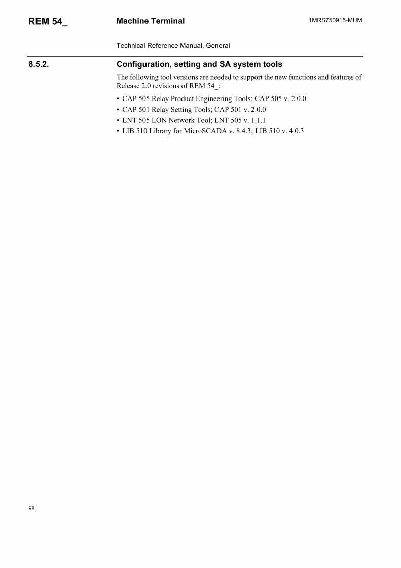
98
1MRS750915-MUMMachine Terminal Technical Reference Manual, General
REM 54_
8.5.2. Configuration, setting and SA system toolsThe following tool versions are needed to support the new functions and features of Release 2.0 revisions of REM 54_:
• CAP 505 Relay Product Engineering Tools; CAP 505 v. 2.0.0• CAP 501 Relay Setting Tools; CAP 501 v. 2.0.0• LNT 505 LON Network Tool; LNT 505 v. 1.1.1• LIB 510 Library for MicroSCADA v. 8.4.3; LIB 510 v. 4.0.3

1MRS750915-MUM REM 54_
99
Machine Terminal Technical Reference Manual, General
9. Abbreviations
AI Analog inputCB Circuit breakerCBFP Circuit breaker failure protectionCPU Central processing unitCT Current transformerDI Digital inputDO Digital outputEMC Electromagnetic compatibilityGND GroundHMI Human-machine interfaceHSPO High-speed power outputI/O Input/outputIRF Internal relay faultLCD Liquid-crystal displayLED Light-emitting diodeLON Locally operating networkL/R Local/remoteLV Low voltageMIMIC A graphic configuration picture on the LCD of a relayMV Nedium voltageNO/NC Normally open/ normally closedPCB Printed circuit boardPLC Programmable logic controllerPO Power outputPOD Protocol object dictionaryPS Power supplyRTD Resistance temperature deviceSMS Substation monitoring systemSNVT Standard network variable typeSO Signal outputSPA Data communication protocol, developed by ABBSPACOM ABB product family
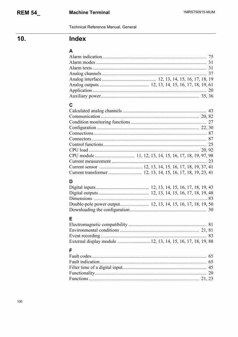
100
1MRS750915-MUMMachine Terminal Technical Reference Manual, General
REM 54_
10. Index
AAlarm indication....................................................................................... 75Alarm modes ............................................................................................ 31Alarm texts ............................................................................................... 31Analog channels ....................................................................................... 37Analog interface ............................................. 12, 13, 14, 15, 16, 17, 18, 19Analog outputs ......................................... 12, 13, 14, 15, 16, 17, 18, 19, 61Application ............................................................................................... 20Auxiliary power.................................................................................. 35, 36
CCalculated analog channels ...................................................................... 43Communication .................................................................................. 20, 82Condition monitoring functions ............................................................... 27Configuration ..................................................................................... 22, 30Connections.............................................................................................. 87Connectors................................................................................................ 87Control functions...................................................................................... 25CPU load ............................................................................................ 20, 92CPU module ................................. 11, 12, 13, 14, 15, 16, 17, 18, 19, 97, 98Current measurement ............................................................................... 23Current sensor .................................... 12, 13, 14, 15, 16, 17, 18, 19, 37, 41Current transformer ............................ 12, 13, 14, 15, 16, 17, 18, 19, 23, 41
DDigital inputs ............................................ 12, 13, 14, 15, 16, 17, 18, 19, 43Digital outputs .......................................... 12, 13, 14, 15, 16, 17, 18, 19, 48Dimensions ............................................................................................... 83Double-pole power output........................ 12, 13, 14, 15, 16, 17, 18, 19, 50Downloading the configuration................................................................ 30
EElectromagnetic compatibility ................................................................. 81Environmental conditions .................................................................. 21, 81Event recording ........................................................................................ 83External display module ........................... 12, 13, 14, 15, 16, 17, 18, 19, 88
FFault codes................................................................................................ 65Fault indication......................................................................................... 65Filter time of a digital input...................................................................... 45Functionality............................................................................................. 20Functions ............................................................................................ 21, 23
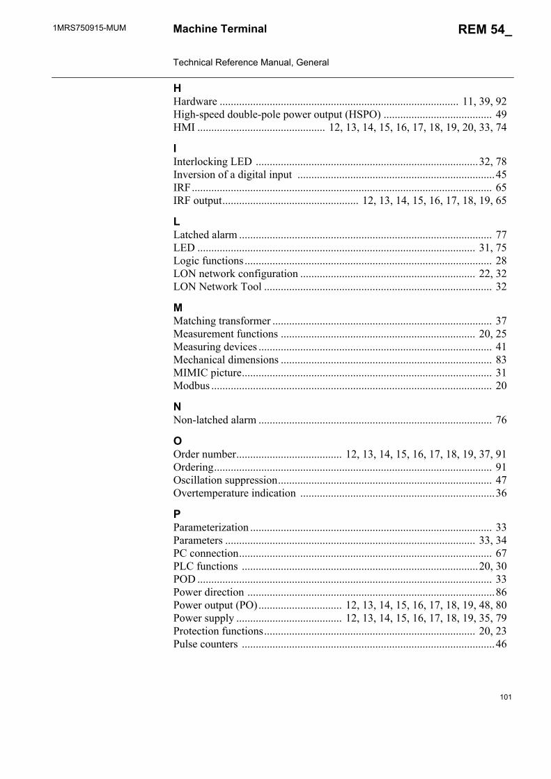
1MRS750915-MUM REM 54_
101
Machine Terminal Technical Reference Manual, General
HHardware ...................................................................................... 11, 39, 92High-speed double-pole power output (HSPO) ....................................... 49HMI .............................................. 12, 13, 14, 15, 16, 17, 18, 19, 20, 33, 74
IInterlocking LED ................................................................................32, 78Inversion of a digital input .......................................................................45IRF............................................................................................................ 65IRF output................................................. 12, 13, 14, 15, 16, 17, 18, 19, 65
LLatched alarm ........................................................................................... 77LED .................................................................................................... 31, 75Logic functions ......................................................................................... 28LON network configuration ............................................................... 22, 32LON Network Tool .................................................................................. 32
MMatching transformer ............................................................................... 37Measurement functions ...................................................................... 20, 25Measuring devices .................................................................................... 41Mechanical dimensions ............................................................................ 83MIMIC picture.......................................................................................... 31Modbus ..................................................................................................... 20
NNon-latched alarm .................................................................................... 76
OOrder number...................................... 12, 13, 14, 15, 16, 17, 18, 19, 37, 91Ordering.................................................................................................... 91Oscillation suppression............................................................................. 47Overtemperature indication ......................................................................36
PParameterization ....................................................................................... 33Parameters .......................................................................................... 33, 34PC connection........................................................................................... 67PLC functions .....................................................................................20, 30POD .......................................................................................................... 33Power direction .........................................................................................86Power output (PO).............................. 12, 13, 14, 15, 16, 17, 18, 19, 48, 80Power supply ...................................... 12, 13, 14, 15, 16, 17, 18, 19, 35, 79Protection functions............................................................................ 20, 23Pulse counters ...........................................................................................46
102
1MRS750915-MUMMachine Terminal Technical Reference Manual, General
REM 54_
RRated frequency........................................................................................ 33Rated values ............................................................................................. 40Relay Configuration Tool............................................................. 22, 30, 39Relay Mimic Editor............................................................................ 22, 31Relay Setting Tool.................................................................................... 34Revisions of REM 54_ ............................................................................. 93Rogowski coil............................................................................... 23, 37, 41RTD/analog inputs ............................. 12, 13, 14, 15, 16, 17, 18, 19, 52, 80RTD/analog module ....................................... 12, 13, 14, 15, 16, 17, 18, 19
SScaling factors .......................................................................................... 40Self-supervision (IRF).............................................................................. 65Sensor channels .............................................. 12, 13, 14, 15, 16, 17, 18, 19Serial communication............................................................................... 66Service...................................................................................................... 90Signal output (SO).............................. 12, 13, 14, 15, 16, 17, 18, 19, 51, 80Single-pole power output ......................... 12, 13, 14, 15, 16, 17, 18, 19, 50SMS bus ............................................................................................. 71, 94Software ................................................................................................... 92Standard functions.................................................................................... 28Storing of parameters ............................................................................... 34
TTemperature supervision .......................................................................... 36Terminal connections ............................................................................... 87Terminal diagrams.................................................................................... 84Tests ......................................................................................................... 81Threshold voltage........................................... 12, 13, 14, 15, 16, 17, 18, 19Transformers .................................................. 12, 13, 14, 15, 16, 17, 18, 19Trip circuit supervision ............................ 12, 13, 14, 15, 16, 17, 18, 19, 63
VVirtual channel ......................................................................................... 43Voltage divider............................................................................. 23, 37, 42Voltage measurement............................................................................... 23Voltage transformer............................ 12, 13, 14, 15, 16, 17, 18, 19, 23, 41


ABB OyDistribution Automation P.O. Box 699FI-65101 VaasaFINLANDTel. +358 10 22 11Fax. +358 10 224 1094www.abb.com/substationautomation
1MR
S75
0915
-MU
M E
N 1
0.20
10