Embed Size (px)
Citation preview
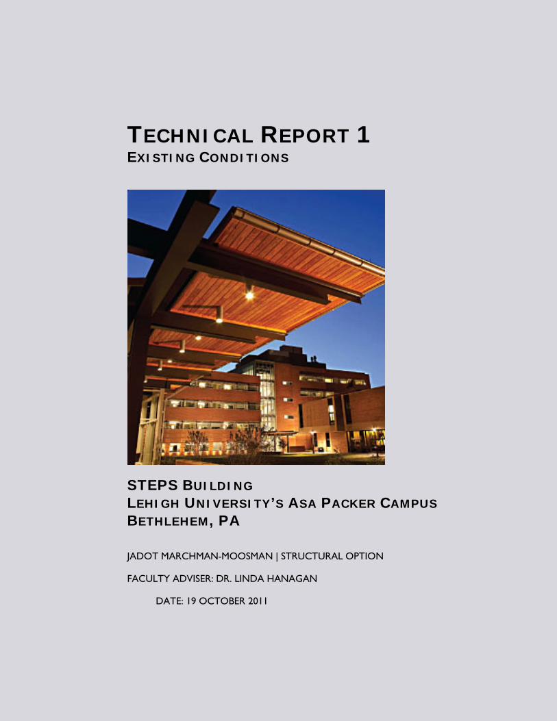
TECHNICAL REPORT 1 EXISTING CONDITIONS
STEPS BUILDING LEHIGH UNIVERSITY’S ASA PACKER CAMPUS BETHLEHEM, PA
JADOT MARCHMAN-MOOSMAN | STRUCTURAL OPTION
FACULTY ADVISER: DR. LINDA HANAGAN
DATE: 19 OCTOBER 2011
TECHNICAL REPORT 1: EXISTING CONDITONS JADOT MARCHMAN-MOOSMAN | STRUCTURAL OPTION | FACULTY ADVISER: DR. LINDA HANAGAN
STEPS BUILDING | LEHIGH UNIVERSITY’S ASA PACKER CAMPUS | BETHLEHEM, PA
2
Table of Contents
1. Executive Summary 3 2. Building Introduction 4 3. Description of Structural System Components 6 3.1 Floor System 6 3.2 Vertical Members 6 3.3 Foundation 6 3.4 Roof System 7 3.5 Lateral System 7 4. Design Codes 8 5. Materials 9 6. Design Gravity Loads 10 6.1 Floor Live Load 10 6.2 Floor Dead Load 10 6.3 Roof Live Load 10 6.4 Roof Dead Load 11 6.5 Roof Snow Load 11 6.5.1 Uniform Roof Snow Load 11 6.5.2 Snow Drift Surcharge 12 6.6 Penthouse Live Load 12 6.7 Penthouse Dead Load 13 6.8 Brick Veneer Façade Dead Load 13 6.9 Glass Curtainwall Dead Load 13 6.10 Penthouse Wall Dead Load 14 7. Wind Pressures 15 8. Seismic Loads 19 8.1 Design Factors 19 8.2 Effective Seismic Weight 20 8.3 Design Seismic Loads 22 9. Gravity Member Spot Checks 23 9.1 Composite Metal Deck and Slab 23 9.2 Composite Beam 24 9.3 Column Gravity Check 26 A.1 Design Snow Load Calculations 28 A.2 Design Wind Pressure Calculations 32 A.3 Design Seismic Load Calculations 38 A.4 Typical Beam Spot Check Calculations 44 A.5 Typical Column Spot Check Calculations 52
TECHNICAL REPORT 1: EXISTING CONDITONS JADOT MARCHMAN-MOOSMAN | STRUCTURAL OPTION | FACULTY ADVISER: DR. LINDA HANAGAN
STEPS BUILDING | LEHIGH UNIVERSITY’S ASA PACKER CAMPUS | BETHLEHEM, PA
3
1. Executive Summary
The purpose of this report is to develop and communicate an understanding the structural system of a building as part of the Penn State Architectural Engineering Department’s Capstone Project, also known as Senior Thesis. The building used for this report was the STEPS Building, located on the Lehigh University Campus in Bethlehem, PA.
The report begins with a description of the building structural system. A concrete slab on composite metal deck transfers floor load to wide-flange steel beams. The beams take advantage of composite action with the concrete topping for added strength. Wide-flange steel columns transfer gravity loads to concrete foundation piers. The foundation piers are tied into shallow reinforced concrete footings that ultimately transfer building loads to the ground.
Information and details needed to compute the gravity load requirements of representative members were determined and tabulated. Seismic and wind load inputs were also determined for use in a future analysis of the lateral load resisting system.
Using this information the adequacy of the steel deck and slab was confirmed. A typical beam and column were then re-designed for gravity loading, and the resulting member was compared to the as-built design. In both cases, the existing member had greater capacity than the designed member, and possible reasons for the discrepancy were discussed.
Supporting calculations are also included in appendices to the report.
TECHNICAL REPORT 1: EXISTING CONDITONS JADOT MARCHMAN-MOOSMAN | STRUCTURAL OPTION | FACULTY ADVISER: DR. LINDA HANAGAN
STEPS BUILDING | LEHIGH UNIVERSITY’S ASA PACKER CAMPUS | BETHLEHEM, PA
4
2. Building Introduction
The Science, Technology, Environment, Policy, Society (STEPS) Building was completed in 2010 as the primary home for the STEPS program at Lehigh University in Bethlehem, PA. The STEPS program aims to bring social sciences, engineering, and hard science activities into spatial proximity to encourage academic collaboration. As a result, the plan contains a mixture of classroom spaces, inter-disciplinary research and teaching laboratories, and faculty offices arranged to integrate the various functions and disciplines.
The four-story “B” wing and five-story “C” wing are steel-frame structures running north-south along the west edge of the site. Flexible moment connections at all column-beam connections provide lateral stability, allowing for an open floor plan well-suited to laboratory, classroom, and graduate office use. A normal weight concrete slab on 3” composite steel deck transfers floor loads to composite beams and girders.
The longitudinal facades are primarily a highly-insulated brick assembly with punch-out style ribbon windows. The transverse facades are almost entirely high-efficiency glazing with rectangular HSS framing, housing student study areas and stairwells.
An atrium with student lounge areas and stairs connects the “B” and “C” wings. For analysis purposes, both wings act together as one structure because the load resisting system continues uninterrupted through the atrium area, and the size of the atrium opening relative to the full diaphragm does not constitute a significant horizontal irregularity that would compromise diaphragm rigidity.
The low-rise “A” wing, which is not investigated in this report, is a one-story steel-frame structure running east to west along the south edge of the site. Its primary features are a 70-seat lecture hall, 12”-deep green roof, extensive glazing, and laminated wood finishing.
The STEPS Building has received LEED Gold certification from the US Green Building Council (USGBC). Sustainable features (including a partial green roof; sunshading and high-efficiency glazing; and custom-sized mechanical systems) were incorporated from the onset of the project to physically embody the STEPS program's forward-looking mission of “collaboration, innovation and scholarship in the areas of science, technology, environment, policy and society.”
TECHNICAL REPORT 1: EXISTING CONDITONS JADOT MARCHMAN-MOOSMAN | STRUCTURAL OPTION | FACULTY ADVISER: DR. LINDA HANAGAN
STEPS BUILDING | LEHIGH UNIVERSITY’S ASA PACKER CAMPUS | BETHLEHEM, PA
5
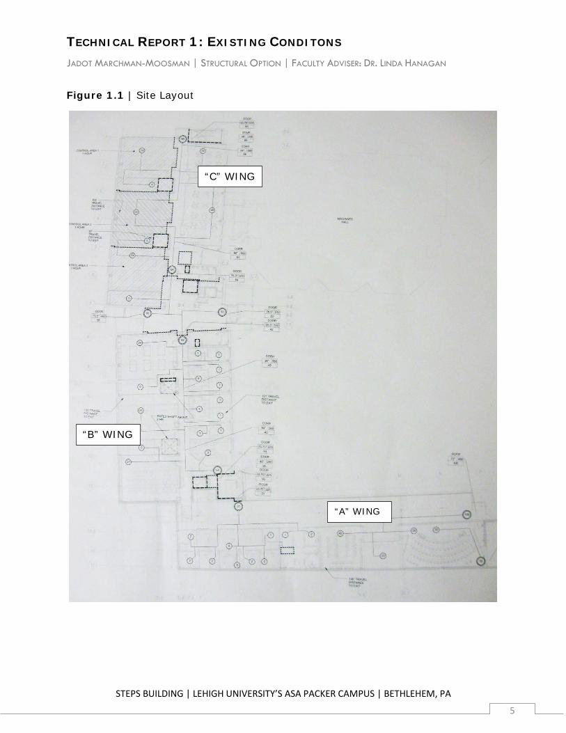
Figure 1.1 | Site Layout
“A” WING
“B” WING
“C” WING
TECHNICAL REPORT 1: EXISTING CONDITONS JADOT MARCHMAN-MOOSMAN | STRUCTURAL OPTION | FACULTY ADVISER: DR. LINDA HANAGAN
STEPS BUILDING | LEHIGH UNIVERSITY’S ASA PACKER CAMPUS | BETHLEHEM, PA
6
3. Description of Structural System Components
3.1 Floor System
A composite floor system comprised of a concrete slab with composite steel deck resting on steel framing supports design loads on all above-grade floors in the “B” and “C” wings. Basement floor loads are transferred directly to the soil by a slab-on-grade. In the longitudinal direction, typical girders span 21'-4” and support one transverse beam at mid-span. Transverse beams span from 36'-11” to 42'-8”.
3” 18-gauge composite deck is oriented longitudinally for a clear span of 10'-8”, with the exception of the two bays at the south end of the “B” wing where the deck is oriented transversely. The composite deck is topped with a 4-1/2” normal weight concrete topping, for a total thickness of 7-1/2”, and reinforced with 6”x6” W2.9 X W2.9 welded wire fabric situated 0-3/4” from the top of the slab.
Wide-flange members support the slab-deck floor system and are designed as simply-supported members due to the properties of the flexible moment connections at the columns (see “Lateral System”). Typical sizes for transverse beams are W24x55 and W24x76, with some local variations. Typical longitudinal girders are W21x44. Studs are employed to transfer flexure-induced shear from the slab to the beams and girders, with most beams having between 28 and 36 studs depending on span.
3.2 Vertical Members
Gravity and lateral loads are carried to the foundation by wide-flange columns oriented for strong-axis bending in the transverse direction due to larger surface area and resulting wind loads. Typical bays arranged with three longitudinal column lines, with one at each edge and one near mid-span.
Typical sizes for the main bearing columns in the lateral support system range from W14x90 to W14x132 on levels 3 to 5, and range from W14x109 to W14x192 on the lower floors. Sizes of other columns vary widely by location and purpose. Column lifts are typically three levels – top of pier to level 3, and level 3 to roof level – except on the upper levels of the shorter “B” wing, where lifts are two levels.
3.3 Foundation
Load transfer to bearing soil is provided by shallow reinforced concrete footings. A 2007 geotechnical analysis performed by Schnabel Engineering's West Chester, PA office determined that the existing subgrade material on site had sufficient bearing capacity to support building loads.
TECHNICAL REPORT 1: EXISTING CONDITONS JADOT MARCHMAN-MOOSMAN | STRUCTURAL OPTION | FACULTY ADVISER: DR. LINDA HANAGAN
STEPS BUILDING | LEHIGH UNIVERSITY’S ASA PACKER CAMPUS | BETHLEHEM, PA
7
Column loads are transferred via base plates to reinforced concrete piers tied into the footings. Exterior columns bear on square footings, with most ranging from 11'-0” to 16'-0” square and 1'-6” to 2'-0” in depth. The interior column line is supported by a mat foundation 18'-0” wide and 3'-0” deep extending the length of the building in the longitudinal direction.
Exterior reinforced concrete foundation walls are supported by strip footings ranging from 2'-0” to 6'-0” in width and 1'-0” to 2'-0” in depth. Foundation walls and piers supporting exterior columns are integrated and cast as one piece. Likewise, the strip footings supporting the foundation walls are integrated with the square footings supporting the exterior columns.
3.4 Roof System
Roof loads are supported by 3” 16-gauge roof deck with a normal weight concrete topping. The topping thickness ranges from 0-1/4” to 4-1/2” to accommodate a 1/4”:1' slope for drainage, for a total slab thickness of 3-1/4” to 7-1/2”. The roof levels are framed very similarly to the floors described above, with typical members in snow-load governed roof areas sized from W24x55 to W24x68.
The roof framing system also supports mechanical equipment in rooftop penthouses, as well as the weight of penthouse square HSS framing and gravity loads transferred from the penthouse roof. The floor system in the mechanical areas matches that of lower floors, with heavier W27x84 shapes.
3.5 Lateral System
Lateral load resistance in both the longitudinal and transverse directions is provided by flexible moment connections at all beam to column connections. The moment frames are continuous to grade, transferring resulting shear and moment to the foundation. Flexible moment connections are sized to resist lateral forces only, and beams are designed as simply-supported members because the moment connections do not have excess capacity to transfer gravity moments to the columns under design lateral loads. Beam webs are connected with angles on each side sized to resist full shear resulting from gravity load. Beam top and bottom flanges are connected with angles to resist moment generated by the lateral load.
Penthouse lateral loads are supported by flexible moment connections at the high roof level in the transverse direction, and by single-angle braced frames designed for tension only in the longitudinal direction. Lateral loads are then transmitted through rigid connections to horizontal roof framing members connected to their supporting columns with flexible moment connections. These beams (typically W27x102) are larger than adjacent members (typically W24x68 or W27x84) to accommodate the additional moment generated by the lateral load.
TECHNICAL REPORT 1: EXISTING CONDITONS JADOT MARCHMAN-MOOSMAN | STRUCTURAL OPTION | FACULTY ADVISER: DR. LINDA HANAGAN
STEPS BUILDING | LEHIGH UNIVERSITY’S ASA PACKER CAMPUS | BETHLEHEM, PA
8
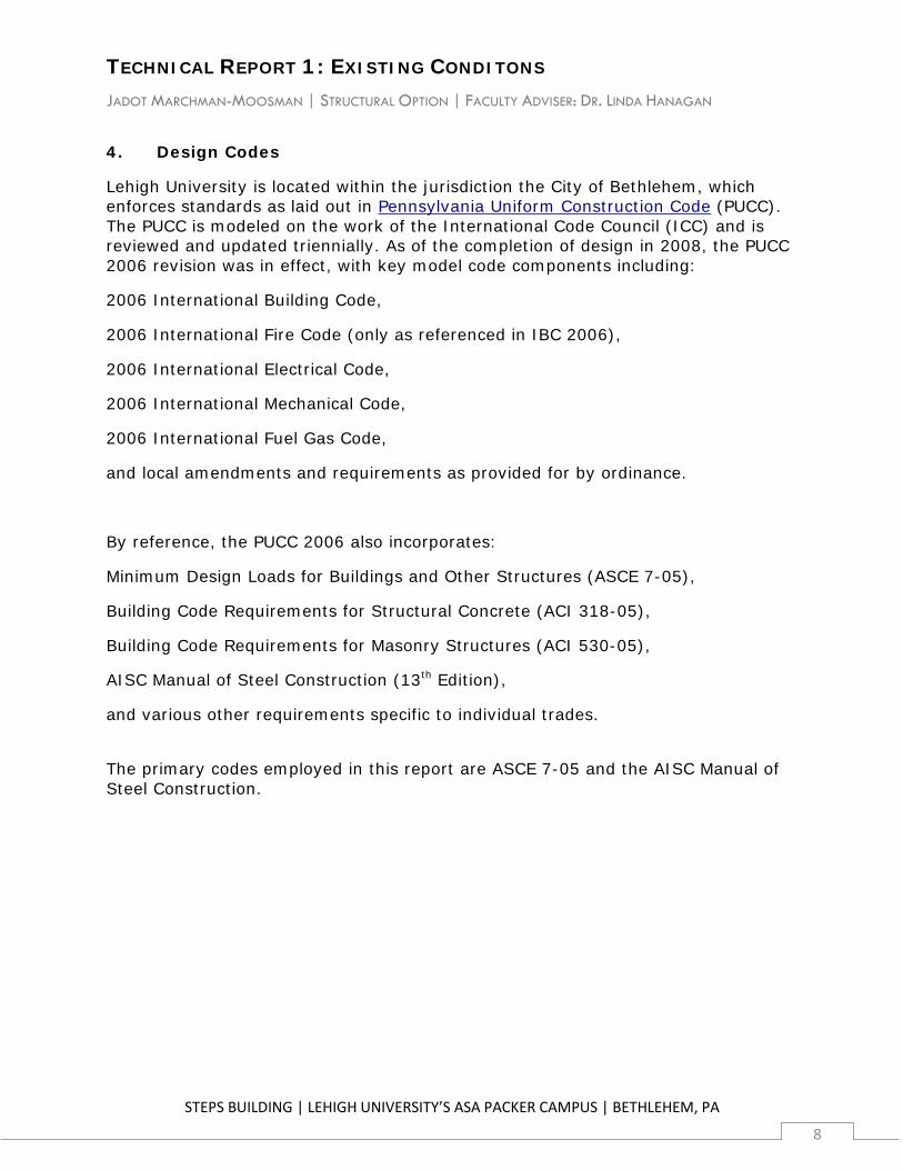
4. Design Codes
Lehigh University is located within the jurisdiction the City of Bethlehem, which enforces standards as laid out in Pennsylvania Uniform Construction Code (PUCC). The PUCC is modeled on the work of the International Code Council (ICC) and is reviewed and updated triennially. As of the completion of design in 2008, the PUCC 2006 revision was in effect, with key model code components including:
2006 International Building Code,
2006 International Fire Code (only as referenced in IBC 2006),
2006 International Electrical Code,
2006 International Mechanical Code,
2006 International Fuel Gas Code,
and local amendments and requirements as provided for by ordinance.
By reference, the PUCC 2006 also incorporates:
Minimum Design Loads for Buildings and Other Structures (ASCE 7-05),
Building Code Requirements for Structural Concrete (ACI 318-05),
Building Code Requirements for Masonry Structures (ACI 530-05),
AISC Manual of Steel Construction (13th Edition),
and various other requirements specific to individual trades.
The primary codes employed in this report are ASCE 7-05 and the AISC Manual of Steel Construction.
TECHNICAL REPORT 1: EXISTING CONDITONS JADOT MARCHMAN-MOOSMAN | STRUCTURAL OPTION | FACULTY ADVISER: DR. LINDA HANAGAN
STEPS BUILDING | LEHIGH UNIVERSITY’S ASA PACKER CAMPUS | BETHLEHEM, PA
9
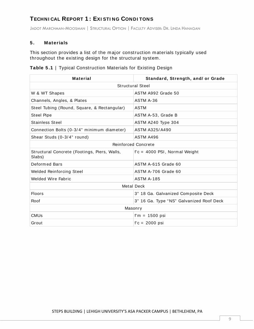
5. Materials
This section provides a list of the major construction materials typically used throughout the existing design for the structural system.
Table 5.1 | Typical Construction Materials for Existing Design
Material Standard, Strength, and/or Grade
Structural Steel
W & WT Shapes ASTM A992 Grade 50
Channels, Angles, & Plates ASTM A-36
Steel Tubing (Round, Square, & Rectangular) ASTM
Steel Pipe ASTM A-53, Grade B
Stainless Steel ASTM A240 Type 304
Connection Bolts (0-3/4” minimum diameter) ASTM A325/A490
Shear Studs (0-3/4” round) ASTM A496
Reinforced Concrete
Structural Concrete (Footings, Piers, Walls, Slabs)
f'c = 4000 PSI, Normal Weight
Deformed Bars ASTM A-615 Grade 60
Welded Reinforcing Steel ASTM A-706 Grade 60
Welded Wire Fabric ASTM A-185
Metal Deck
Floors 3” 18 Ga. Galvanized Composite Deck
Roof 3” 16 Ga. Type “NS” Galvanized Roof Deck
Masonry
CMUs f'm = 1500 psi
Grout f'c = 2000 psi
TECHNICAL REPORT 1: EXISTING CONDITONS JADOT MARCHMAN-MOOSMAN | STRUCTURAL OPTION | FACULTY ADVISER: DR. LINDA HANAGAN
STEPS BUILDING | LEHIGH UNIVERSITY’S ASA PACKER CAMPUS | BETHLEHEM, PA
10
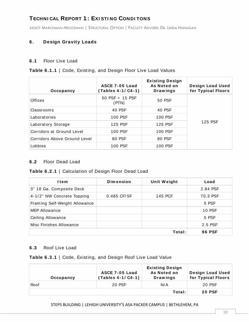
6. Design Gravity Loads
6.1 Floor Live Load
Table 6.1.1 | Code, Existing, and Design Floor Live Load Values
Occupancy ASCE 7-05 Load
(Tables 4-1/C4-1)
Existing Design As Noted on
Drawings Design Load Used for Typical Floors
Offices 50 PSF + 15 PSF (PTN) 50 PSF
125 PSF
Classrooms 40 PSF 40 PSF
Laboratories 100 PSF 100 PSF
Laboratory Storage 125 PSF 125 PSF
Corridors at Ground Level 100 PSF 100 PSF
Corridors Above Ground Level 80 PSF 80 PSF
Lobbies 100 PSF 100 PSF
6.2 Floor Dead Load
Table 6.2.1 | Calculation of Design Floor Dead Load
Item Dimension Unit Weight Load
3” 18 Ga. Composite Deck 2.84 PSF
4-1/2” NW Concrete Topping 0.485 CF/SF 145 PCF 70.3 PSF
Framing Self-Weight Allowance 5 PSF
MEP Allowance 10 PSF
Ceiling Allowance 5 PSF
Misc Finishes Allowance 2.5 PSF
Total: 96 PSF
6.3 Roof Live Load
Table 6.3.1 | Code, Existing, and Design Roof Live Load Value
Occupancy ASCE 7-05 Load
(Tables 4-1/C4-1)
Existing Design As Noted on
Drawings Design Load Used for Typical Floors
Roof 20 PSF N/A 20 PSF
Total: 20 PSF
TECHNICAL REPORT 1: EXISTING CONDITONS JADOT MARCHMAN-MOOSMAN | STRUCTURAL OPTION | FACULTY ADVISER: DR. LINDA HANAGAN
STEPS BUILDING | LEHIGH UNIVERSITY’S ASA PACKER CAMPUS | BETHLEHEM, PA
11
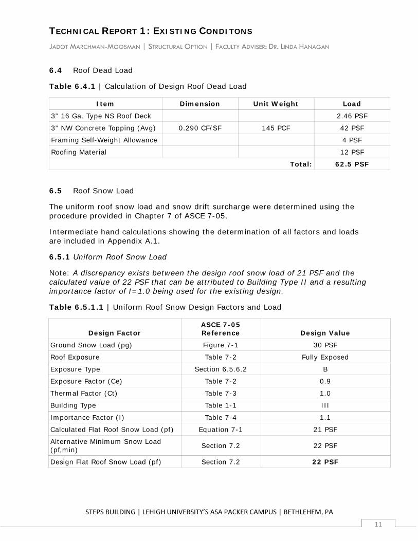
6.4 Roof Dead Load
Table 6.4.1 | Calculation of Design Roof Dead Load
Item Dimension Unit Weight Load
3” 16 Ga. Type NS Roof Deck 2.46 PSF
3” NW Concrete Topping (Avg) 0.290 CF/SF 145 PCF 42 PSF
Framing Self-Weight Allowance 4 PSF
Roofing Material 12 PSF
Total: 62.5 PSF
6.5 Roof Snow Load
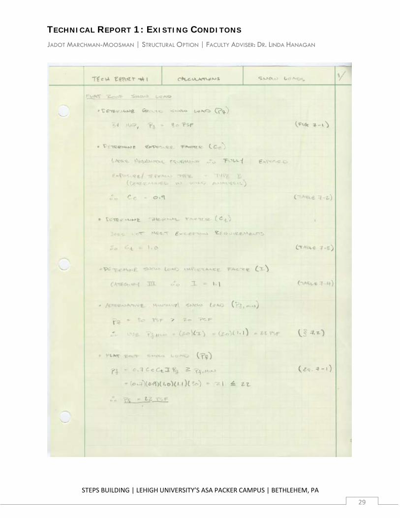
The uniform roof snow load and snow drift surcharge were determined using the procedure provided in Chapter 7 of ASCE 7-05.
Intermediate hand calculations showing the determination of all factors and loads are included in Appendix A.1.
6.5.1 Uniform Roof Snow Load
Note: A discrepancy exists between the design roof snow load of 21 PSF and the calculated value of 22 PSF that can be attributed to Building Type II and a resulting importance factor of I=1.0 being used for the existing design.
Table 6.5.1.1 | Uniform Roof Snow Design Factors and Load
Design Factor ASCE 7-05 Reference Design Value
Ground Snow Load (pg) Figure 7-1 30 PSF
Roof Exposure Table 7-2 Fully Exposed
Exposure Type Section 6.5.6.2 B
Exposure Factor (Ce) Table 7-2 0.9
Thermal Factor (Ct) Table 7-3 1.0
Building Type Table 1-1 III
Importance Factor (I) Table 7-4 1.1
Calculated Flat Roof Snow Load (pf) Equation 7-1 21 PSF
Alternative Minimum Snow Load (pf,min) Section 7.2 22 PSF
Design Flat Roof Snow Load (pf) Section 7.2 22 PSF
TECHNICAL REPORT 1: EXISTING CONDITONS JADOT MARCHMAN-MOOSMAN | STRUCTURAL OPTION | FACULTY ADVISER: DR. LINDA HANAGAN
STEPS BUILDING | LEHIGH UNIVERSITY’S ASA PACKER CAMPUS | BETHLEHEM, PA
12
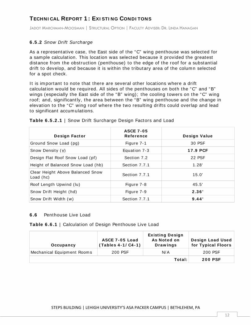
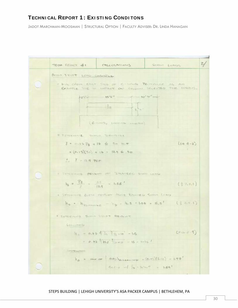
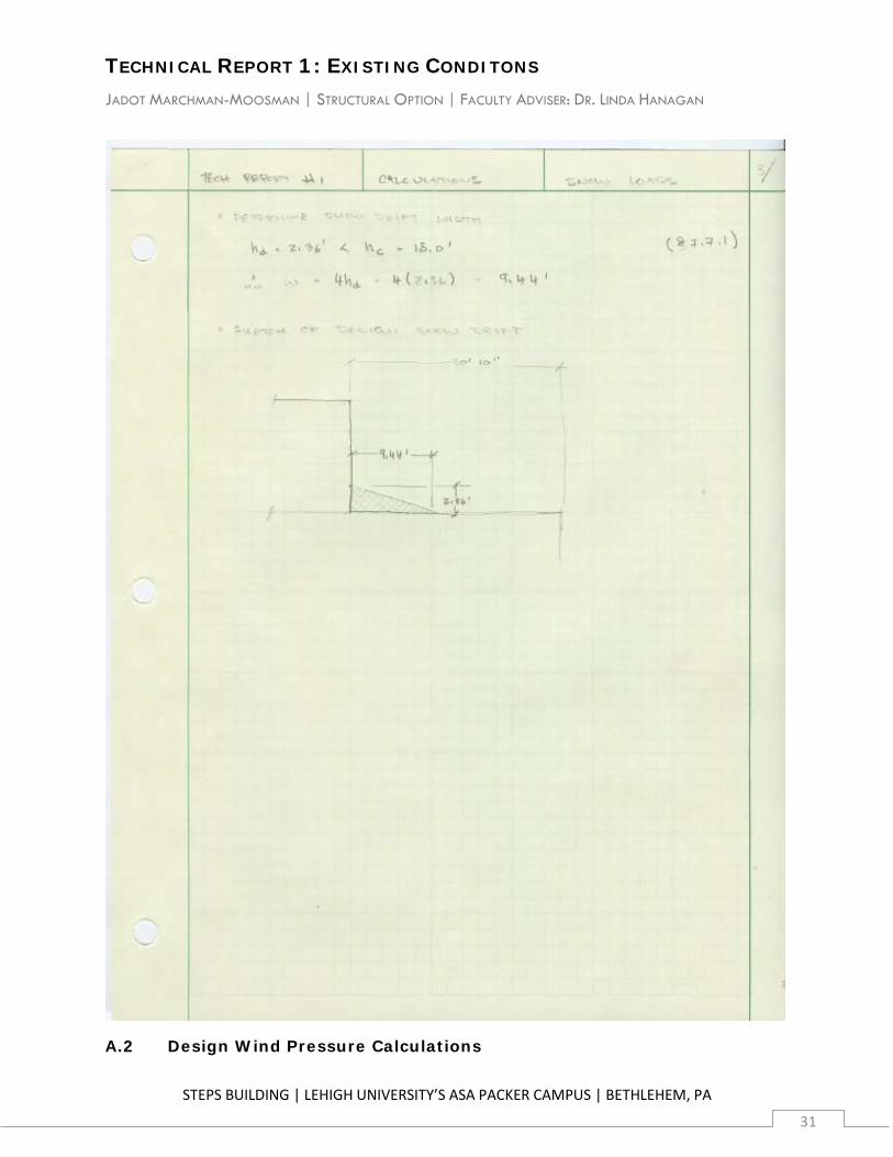
6.5.2 Snow Drift Surcharge
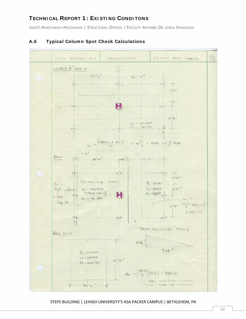
As a representative case, the East side of the “C” wing penthouse was selected for a sample calculation. This location was selected because it provided the greatest distance from the obstruction (penthouse) to the edge of the roof for a substantial drift to develop, and because it is within the tributary area of the column selected for a spot check.
It is important to note that there are several other locations where a drift calculation would be required. All sides of the penthouses on both the “C” and “B” wings (especially the East side of the “B” wing); the cooling towers on the “C” wing roof; and, significantly, the area between the “B” wing penthouse and the change in elevation to the “C” wing roof where the two resulting drifts could overlap and lead to significant accumulations.
Table 6.5.2.1 | Snow Drift Surcharge Design Factors and Load
Design Factor ASCE 7-05 Reference Design Value
Ground Snow Load (pg) Figure 7-1 30 PSF
Snow Density (γ) Equation 7-3 17.9 PCF
Design Flat Roof Snow Load (pf) Section 7.2 22 PSF
Height of Balanced Snow Load (hb) Section 7.7.1 1.28'
Clear Height Above Balanced Snow Load (hc) Section 7.7.1 15.0'
Roof Length Upwind (lu) Figure 7-8 45.5'
Snow Drift Height (hd) Figure 7-9 2.36'
Snow Drift Width (w) Section 7.7.1 9.44'
6.6 Penthouse Live Load
Table 6.6.1 | Calculation of Design Penthouse Live Load
Occupancy ASCE 7-05 Load
(Tables 4-1/C4-1)
Existing Design As Noted on
Drawings Design Load Used for Typical Floors
Mechanical Equipment Rooms 200 PSF N/A 200 PSF
Total: 200 PSF
TECHNICAL REPORT 1: EXISTING CONDITONS JADOT MARCHMAN-MOOSMAN | STRUCTURAL OPTION | FACULTY ADVISER: DR. LINDA HANAGAN
STEPS BUILDING | LEHIGH UNIVERSITY’S ASA PACKER CAMPUS | BETHLEHEM, PA
13
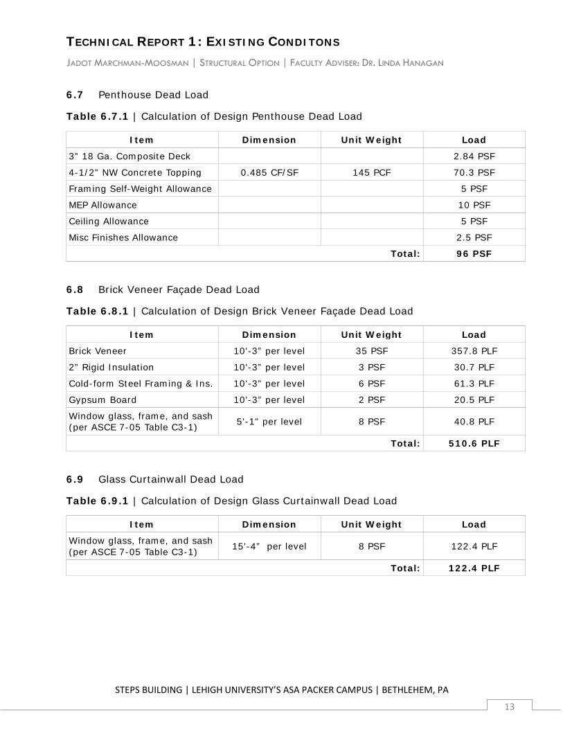
6.7 Penthouse Dead Load
Table 6.7.1 | Calculation of Design Penthouse Dead Load
Item Dimension Unit Weight Load
3” 18 Ga. Composite Deck 2.84 PSF
4-1/2” NW Concrete Topping 0.485 CF/SF 145 PCF 70.3 PSF
Framing Self-Weight Allowance 5 PSF
MEP Allowance 10 PSF
Ceiling Allowance 5 PSF
Misc Finishes Allowance 2.5 PSF
Total: 96 PSF
6.8 Brick Veneer Façade Dead Load
Table 6.8.1 | Calculation of Design Brick Veneer Façade Dead Load
Item Dimension Unit Weight Load
Brick Veneer 10'-3” per level 35 PSF 357.8 PLF
2” Rigid Insulation 10'-3” per level 3 PSF 30.7 PLF
Cold-form Steel Framing & Ins. 10'-3” per level 6 PSF 61.3 PLF
Gypsum Board 10'-3” per level 2 PSF 20.5 PLF
Window glass, frame, and sash (per ASCE 7-05 Table C3-1) 5'-1” per level 8 PSF 40.8 PLF
Total: 510.6 PLF
6.9 Glass Curtainwall Dead Load
Table 6.9.1 | Calculation of Design Glass Curtainwall Dead Load
Item Dimension Unit Weight Load
Window glass, frame, and sash (per ASCE 7-05 Table C3-1) 15'-4” per level 8 PSF 122.4 PLF
Total: 122.4 PLF
TECHNICAL REPORT 1: EXISTING CONDITONS JADOT MARCHMAN-MOOSMAN | STRUCTURAL OPTION | FACULTY ADVISER: DR. LINDA HANAGAN
STEPS BUILDING | LEHIGH UNIVERSITY’S ASA PACKER CAMPUS | BETHLEHEM, PA
14
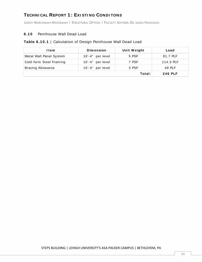
6.10 Penthouse Wall Dead Load
Table 6.10.1 | Calculation of Design Penthouse Wall Dead Load
Item Dimension Unit Weight Load
Metal Wall Panel System 16'-4” per level 5 PSF 81.7 PLF
Cold-form Steel Framing 16'-4” per level 7 PSF 114.3 PLF
Bracing Allowance 16'-4” per level 3 PSF 49 PLF
Total: 246 PLF
TECHNICAL REPORT 1: EXISTING CONDITONS JADOT MARCHMAN-MOOSMAN | STRUCTURAL OPTION | FACULTY ADVISER: DR. LINDA HANAGAN
STEPS BUILDING | LEHIGH UNIVERSITY’S ASA PACKER CAMPUS | BETHLEHEM, PA
15
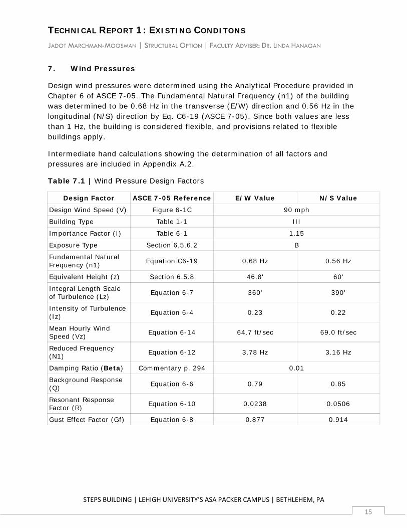
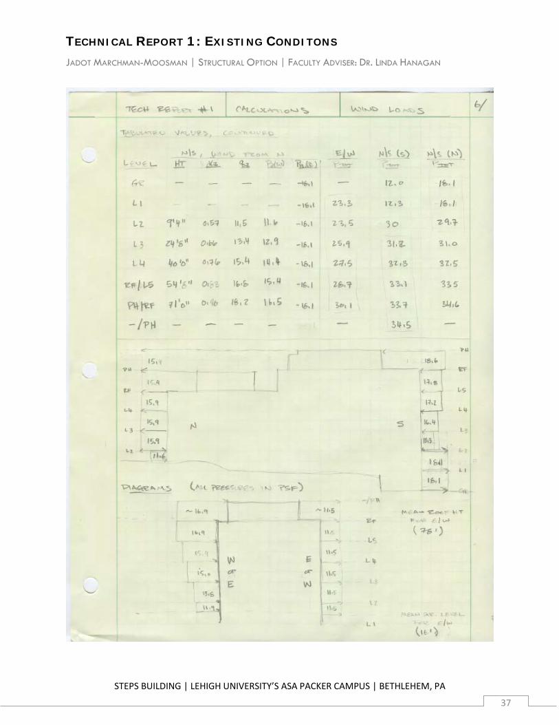
7. Wind Pressures
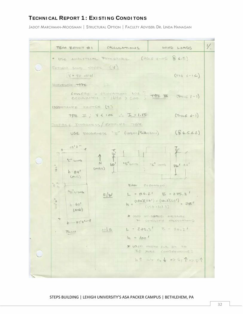
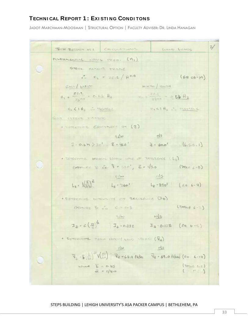
Design wind pressures were determined using the Analytical Procedure provided in Chapter 6 of ASCE 7-05. The Fundamental Natural Frequency (n1) of the building was determined to be 0.68 Hz in the transverse (E/W) direction and 0.56 Hz in the longitudinal (N/S) direction by Eq. C6-19 (ASCE 7-05). Since both values are less than 1 Hz, the building is considered flexible, and provisions related to flexible buildings apply.
Intermediate hand calculations showing the determination of all factors and pressures are included in Appendix A.2.
Table 7.1 | Wind Pressure Design Factors
Design Factor ASCE 7-05 Reference E/W Value N/S Value
Design Wind Speed (V) Figure 6-1C 90 mph
Building Type Table 1-1 III
Importance Factor (I) Table 6-1 1.15
Exposure Type Section 6.5.6.2 B
Fundamental Natural Frequency (n1) Equation C6-19 0.68 Hz 0.56 Hz
Equivalent Height (z) Section 6.5.8 46.8' 60'
Integral Length Scale of Turbulence (Lz) Equation 6-7 360' 390'
Intensity of Turbulence (Iz) Equation 6-4 0.23 0.22
Mean Hourly Wind Speed (Vz) Equation 6-14 64.7 ft/sec 69.0 ft/sec
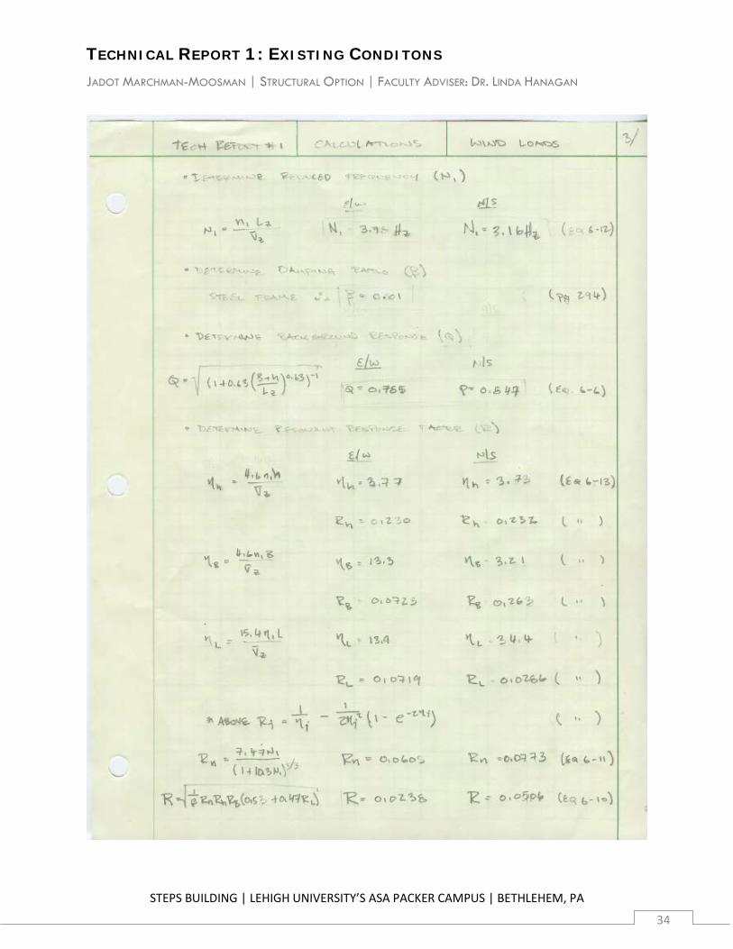
Reduced Frequency (N1) Equation 6-12 3.78 Hz 3.16 Hz
Damping Ratio (Beta) Commentary p. 294 0.01
Background Response (Q) Equation 6-6 0.79 0.85
Resonant Response Factor (R) Equation 6-10 0.0238 0.0506
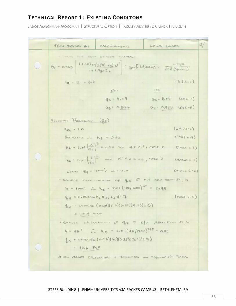
Gust Effect Factor (Gf) Equation 6-8 0.877 0.914
TECHNICAL REPORT 1: EXISTING CONDITONS JADOT MARCHMAN-MOOSMAN | STRUCTURAL OPTION | FACULTY ADVISER: DR. LINDA HANAGAN
STEPS BUILDING | LEHIGH UNIVERSITY’S ASA PACKER CAMPUS | BETHLEHEM, PA
16
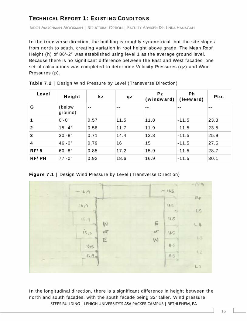
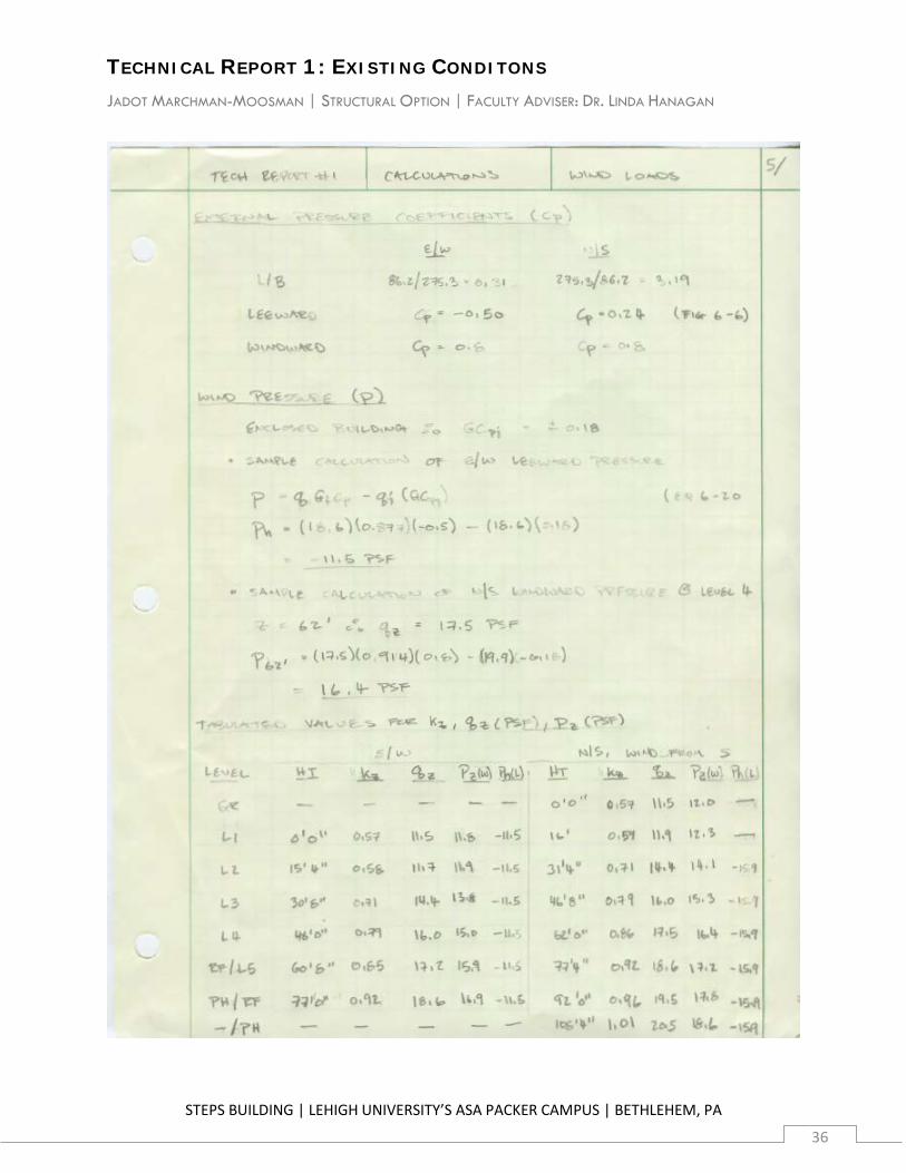
In the transverse direction, the building is roughly symmetrical, but the site slopes from north to south, creating variation in roof height above grade. The Mean Roof Height (h) of 86'-2” was established using level 1 as the average ground level. Because there is no significant difference between the East and West facades, one set of calculations was completed to determine Velocity Pressures (qz) and Wind Pressures (p).
Table 7.2 | Design Wind Pressure by Level (Transverse Direction)
Level Height kz qz Pz
(windward) Ph
(leeward) Ptot
G (below ground)
-- -- -- -- --
1 0'-0” 0.57 11.5 11.8 -11.5 23.3
2 15'-4” 0.58 11.7 11.9 -11.5 23.5
3 30'-8” 0.71 14.4 13.8 -11.5 25.9
4 46'-0” 0.79 16 15 -11.5 27.5
RF/5 60'-8” 0.85 17.2 15.9 -11.5 28.7
RF/PH 77'-0” 0.92 18.6 16.9 -11.5 30.1
Figure 7.1 | Design Wind Pressure by Level (Transverse Direction)
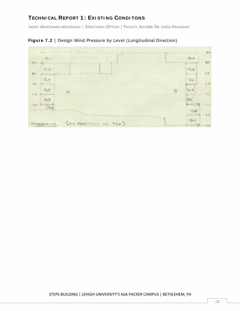
In the longitudinal direction, there is a significant difference in height between the north and south facades, with the south facade being 32' taller. Wind pressure
TECHNICAL REPORT 1: EXISTING CONDITONS JADOT MARCHMAN-MOOSMAN | STRUCTURAL OPTION | FACULTY ADVISER: DR. LINDA HANAGAN
STEPS BUILDING | LEHIGH UNIVERSITY’S ASA PACKER CAMPUS | BETHLEHEM, PA
17
factors were calculated using the south facade Mean Roof Height (h) of 100' to generate conservative results. Velocity Pressures (qz) and Wind Pressures (p) were then calculated once assuming wind from the north and once assuming wind from the south to determine the worst-case loading scenario for each story. From level G (below grade) to level 2 (9'-4”) measured from the base of the north facade, wind from the north created larger pressures, primarily resulting from leeward pressure on exposed south facade from level G to level 2. From level 3 (46'-8”) to the “C” wing Penthouse Roof (108'-4”) measured from the base of the south facade, wind from the south created larger pressures, resulting from the greater height of the south facade. The greatest absolute total pressure combinations from each analysis were then combined to generate the wost-case values for story shear.
Table 7.3 | Design Wind Pressure by Level (Longitudinal Direction)
Level (“C”/ “B”
wings) Height kz qz Pz
(windward) Ph
(leeward) Ptot
G* (below grade)
-- -- -- -18.1 18.1
1* (below grade)
-- -- -- -18.1 18.1
2* 9'-4” 0.57 11.5 11.6 -18.1 29.7
3 46'-8' 0.79 16.0 15.3 -15.9 31.2
4 62'-0” 0.86 17.5 16.4 -15.9 32.3
RF/5 77'-4” 0.92 18.6 17.2 -15.9 33.1
PH/RF 92'-0” 0.96 19.5 17.8 -15.9 33.7
--/PH 108'-4” 1.01 20.5 18.6 -15.9 34.5 * Dimensions and values for these levels are based on the north facade. All other dimensions and values are based on south facade. See Appendix [X] for complete values for each facade.
TECHNICAL REPORT 1: EXISTING CONDITONS JADOT MARCHMAN-MOOSMAN | STRUCTURAL OPTION | FACULTY ADVISER: DR. LINDA HANAGAN
STEPS BUILDING | LEHIGH UNIVERSITY’S ASA PACKER CAMPUS | BETHLEHEM, PA
18
Figure 7.2 | Design Wind Pressure by Level (Longitudinal Direction)
TECHNICAL REPORT 1: EXISTING CONDITONS JADOT MARCHMAN-MOOSMAN | STRUCTURAL OPTION | FACULTY ADVISER: DR. LINDA HANAGAN
STEPS BUILDING | LEHIGH UNIVERSITY’S ASA PACKER CAMPUS | BETHLEHEM, PA
19
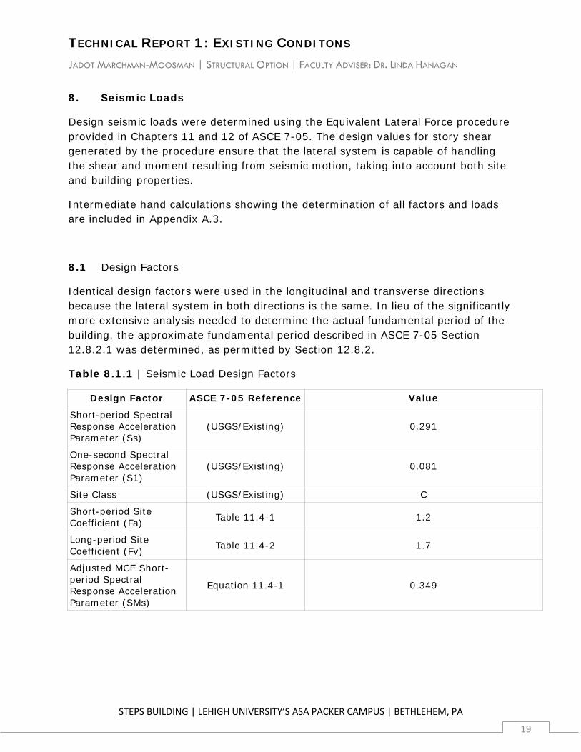
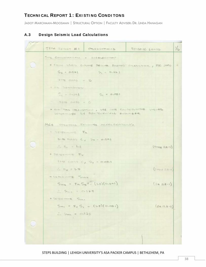
8. Seismic Loads
Design seismic loads were determined using the Equivalent Lateral Force procedure provided in Chapters 11 and 12 of ASCE 7-05. The design values for story shear generated by the procedure ensure that the lateral system is capable of handling the shear and moment resulting from seismic motion, taking into account both site and building properties.
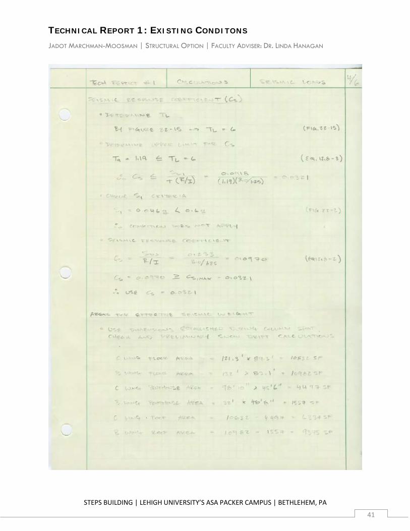
Intermediate hand calculations showing the determination of all factors and loads are included in Appendix A.3.
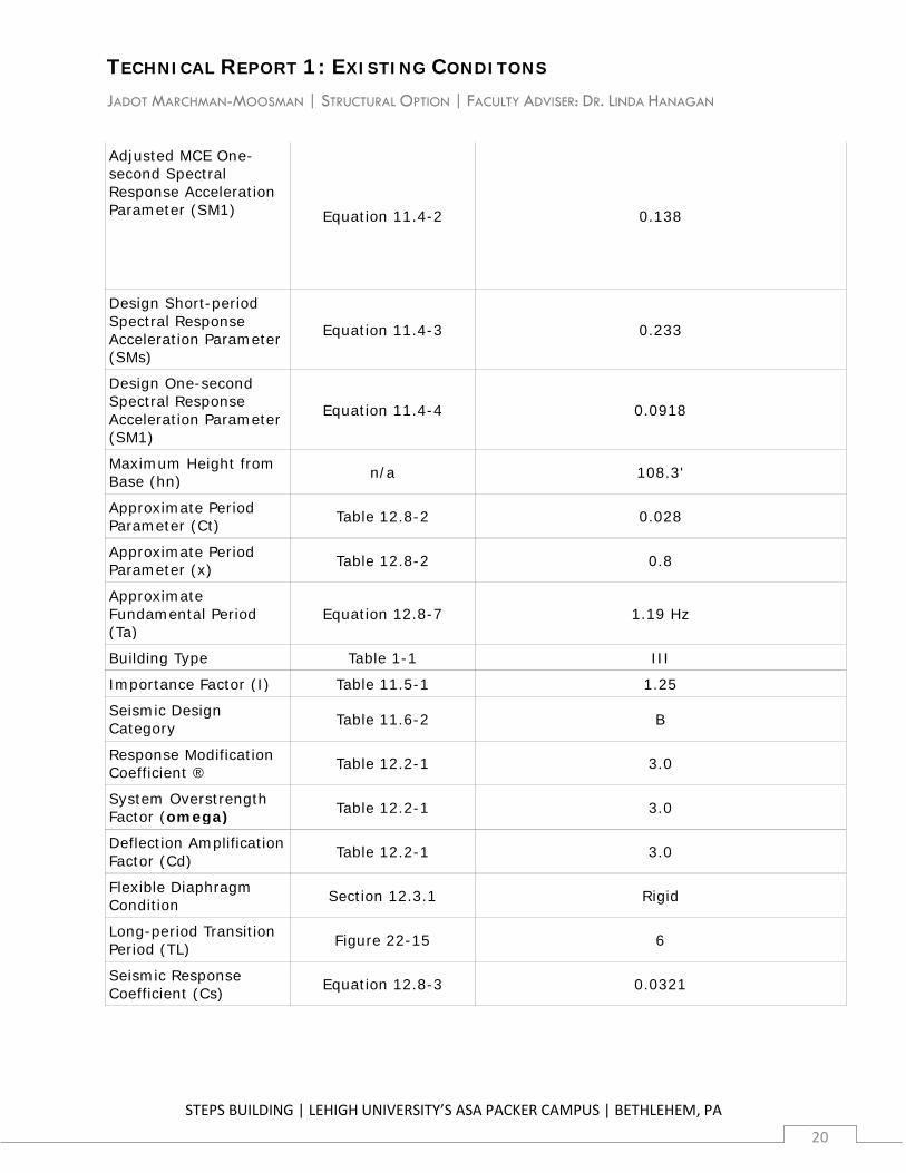
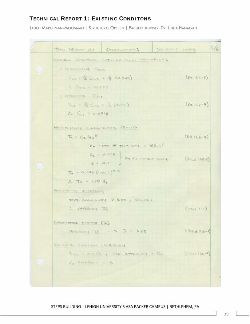
8.1 Design Factors
Identical design factors were used in the longitudinal and transverse directions because the lateral system in both directions is the same. In lieu of the significantly more extensive analysis needed to determine the actual fundamental period of the building, the approximate fundamental period described in ASCE 7-05 Section 12.8.2.1 was determined, as permitted by Section 12.8.2.
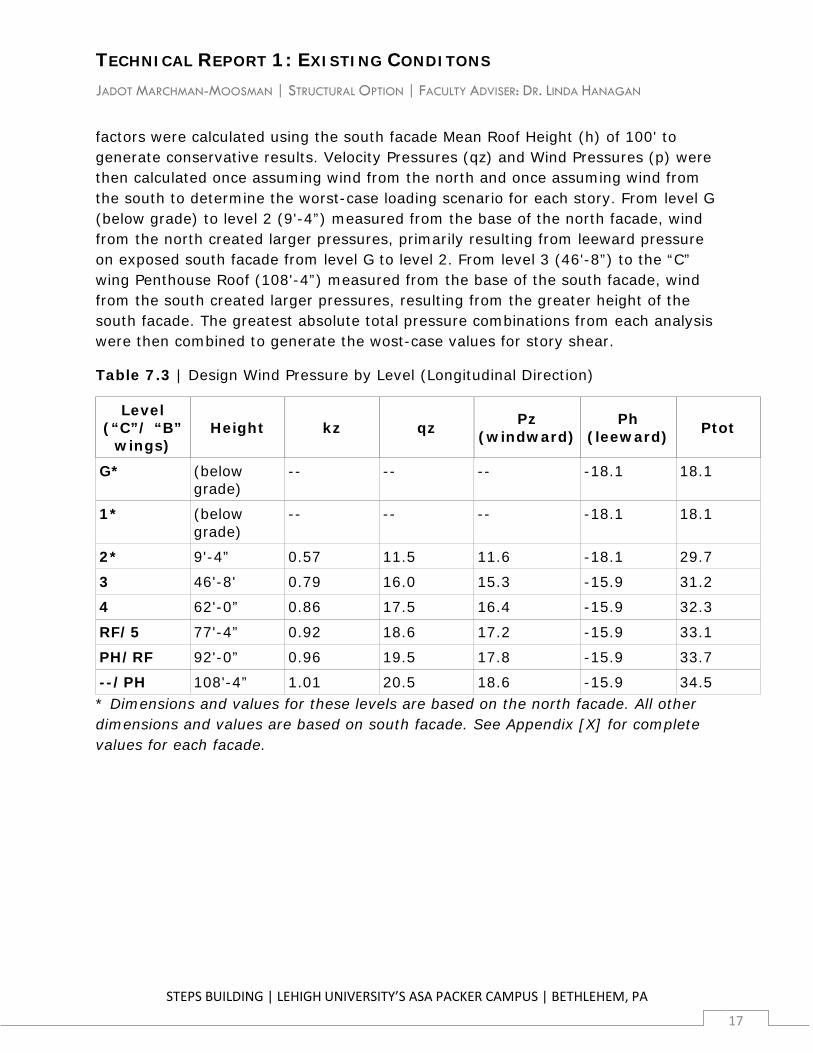
Table 8.1.1 | Seismic Load Design Factors
Design Factor ASCE 7-05 Reference Value
Short-period Spectral Response Acceleration Parameter (Ss)
(USGS/Existing) 0.291
One-second Spectral Response Acceleration Parameter (S1)
(USGS/Existing) 0.081
Site Class (USGS/Existing) C
Short-period Site Coefficient (Fa) Table 11.4-1 1.2
Long-period Site Coefficient (Fv) Table 11.4-2 1.7
Adjusted MCE Short-period Spectral Response Acceleration Parameter (SMs)
Equation 11.4-1 0.349
TECHNICAL REPORT 1: EXISTING CONDITONS JADOT MARCHMAN-MOOSMAN | STRUCTURAL OPTION | FACULTY ADVISER: DR. LINDA HANAGAN
STEPS BUILDING | LEHIGH UNIVERSITY’S ASA PACKER CAMPUS | BETHLEHEM, PA
20
Adjusted MCE One-second Spectral Response Acceleration Parameter (SM1) Equation 11.4-2 0.138
Design Short-period Spectral Response Acceleration Parameter (SMs)
Equation 11.4-3 0.233
Design One-second Spectral Response Acceleration Parameter (SM1)
Equation 11.4-4 0.0918
Maximum Height from Base (hn) n/a 108.3'
Approximate Period Parameter (Ct) Table 12.8-2 0.028
Approximate Period Parameter (x) Table 12.8-2 0.8
Approximate Fundamental Period (Ta)
Equation 12.8-7 1.19 Hz
Building Type Table 1-1 III
Importance Factor (I) Table 11.5-1 1.25
Seismic Design Category Table 11.6-2 B
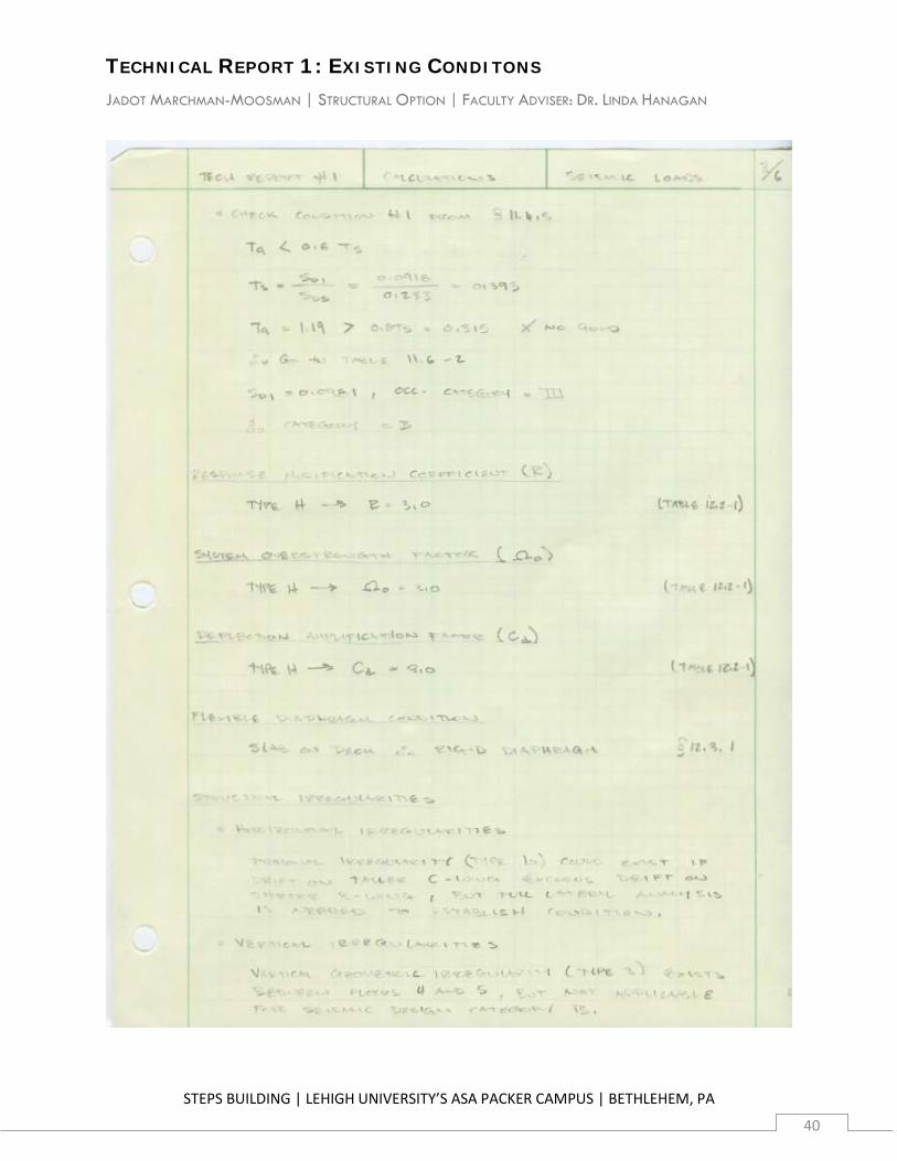
Response Modification Coefficient ® Table 12.2-1 3.0
System Overstrength Factor (omega) Table 12.2-1 3.0
Deflection Amplification Factor (Cd) Table 12.2-1 3.0
Flexible Diaphragm Condition Section 12.3.1 Rigid
Long-period Transition Period (TL) Figure 22-15 6
Seismic Response Coefficient (Cs) Equation 12.8-3 0.0321
TECHNICAL REPORT 1: EXISTING CONDITONS JADOT MARCHMAN-MOOSMAN | STRUCTURAL OPTION | FACULTY ADVISER: DR. LINDA HANAGAN
STEPS BUILDING | LEHIGH UNIVERSITY’S ASA PACKER CAMPUS | BETHLEHEM, PA
21
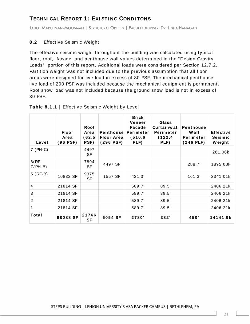
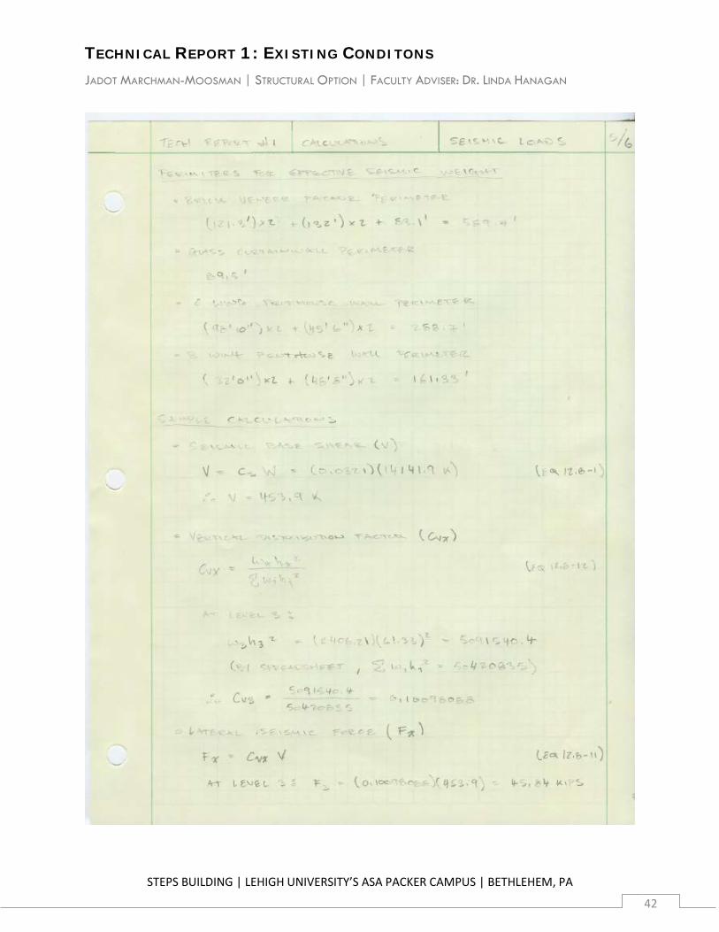
8.2 Effective Seismic Weight
The effective seismic weight throughout the building was calculated using typical floor, roof, facade, and penthouse wall values determined in the “Design Gravity Loads” portion of this report. Additional loads were considered per Section 12.7.2. Partition weight was not included due to the previous assumption that all floor areas were designed for live load in excess of 80 PSF. The mechanical penthouse live load of 200 PSF was included because the mechanical equipment is permanent. Roof snow load was not included because the ground snow load is not in excess of 30 PSF.
Table 8.1.1 | Effective Seismic Weight by Level
Level
Floor Area
(96 PSF)
Roof Area (62.5 PSF)
Penthouse Floor Area (296 PSF)
Brick Veneer Facade
Perimeter (510.6 PLF)
Glass Curtainwall Perimeter
(122.4 PLF)
Penthouse Wall
Perimeter (246 PLF)
Effective Seismic Weight
7 (PH-C) 4497 SF 281.06k
6(RF-C/PH-B) 7894
SF 4497 SF 288.7' 1895.08k
5 (RF-B) 10832 SF 9375 SF 1557 SF 421.3' 161.3' 2341.01k
4 21814 SF 589.7' 89.5' 2406.21k
3 21814 SF 589.7' 89.5' 2406.21k
2 21814 SF 589.7' 89.5' 2406.21k
1 21814 SF 589.7' 89.5' 2406.21k
Total 98088 SF 21766 SF 6054 SF 2780' 382' 450' 14141.9k
TECHNICAL REPORT 1: EXISTING CONDITONS JADOT MARCHMAN-MOOSMAN | STRUCTURAL OPTION | FACULTY ADVISER: DR. LINDA HANAGAN
STEPS BUILDING | LEHIGH UNIVERSITY’S ASA PACKER CAMPUS | BETHLEHEM, PA
22
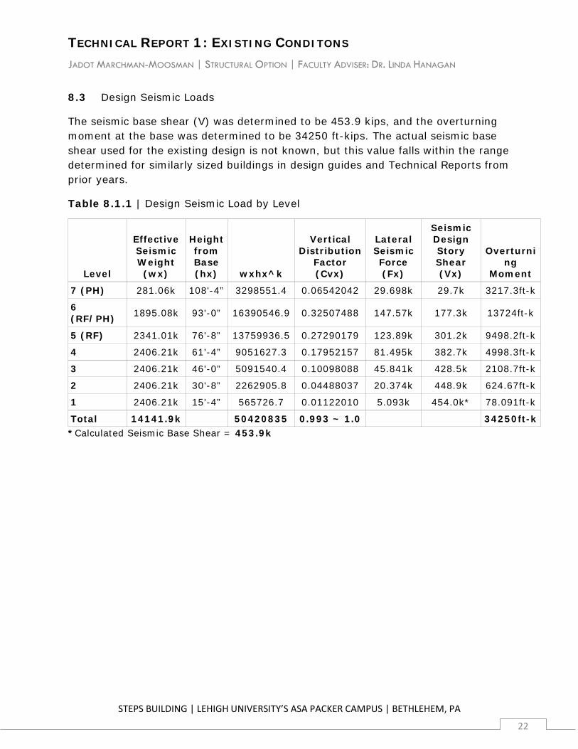
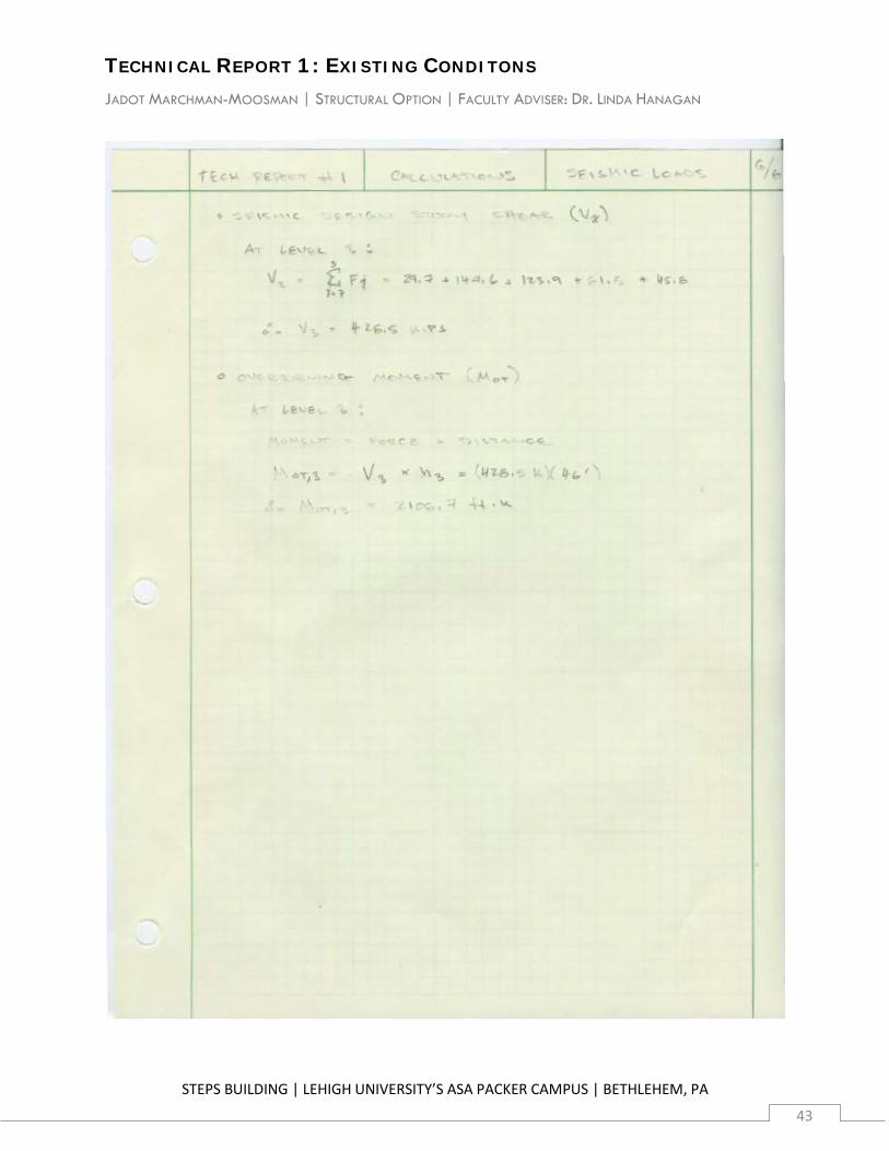
8.3 Design Seismic Loads
The seismic base shear (V) was determined to be 453.9 kips, and the overturning moment at the base was determined to be 34250 ft-kips. The actual seismic base shear used for the existing design is not known, but this value falls within the range determined for similarly sized buildings in design guides and Technical Reports from prior years.
Table 8.1.1 | Design Seismic Load by Level
Level
Effective Seismic Weight (wx)
Height from Base (hx) wxhx^k
Vertical Distribution
Factor (Cvx)
Lateral Seismic Force (Fx)
Seismic Design Story Shear (Vx)
Overturning
Moment
7 (PH) 281.06k 108'-4” 3298551.4 0.06542042 29.698k 29.7k 3217.3ft-k
6 (RF/PH) 1895.08k 93'-0” 16390546.9 0.32507488 147.57k 177.3k 13724ft-k
5 (RF) 2341.01k 76'-8” 13759936.5 0.27290179 123.89k 301.2k 9498.2ft-k
4 2406.21k 61'-4” 9051627.3 0.17952157 81.495k 382.7k 4998.3ft-k
3 2406.21k 46'-0” 5091540.4 0.10098088 45.841k 428.5k 2108.7ft-k
2 2406.21k 30'-8” 2262905.8 0.04488037 20.374k 448.9k 624.67ft-k
1 2406.21k 15'-4” 565726.7 0.01122010 5.093k 454.0k* 78.091ft-k
Total 14141.9k 50420835 0.993 ~ 1.0 34250ft-k *Calculated Seismic Base Shear = 453.9k
TECHNICAL REPORT 1: EXISTING CONDITONS JADOT MARCHMAN-MOOSMAN | STRUCTURAL OPTION | FACULTY ADVISER: DR. LINDA HANAGAN
STEPS BUILDING | LEHIGH UNIVERSITY’S ASA PACKER CAMPUS | BETHLEHEM, PA
23
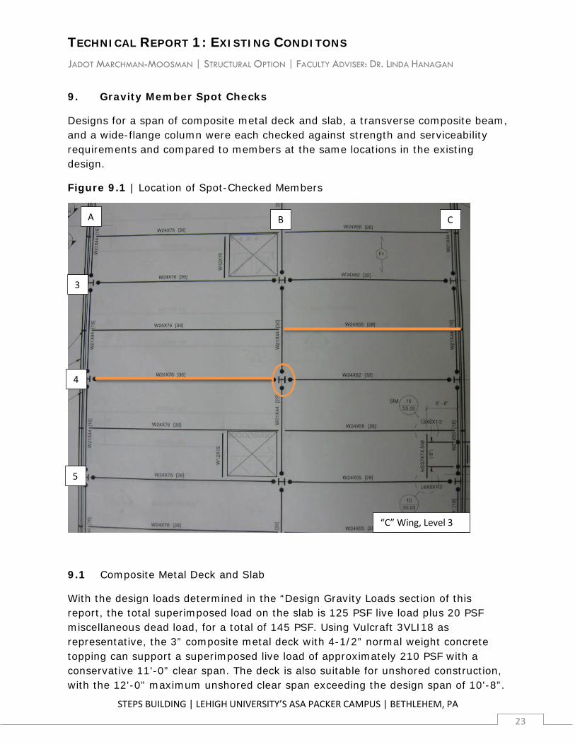
9. Gravity Member Spot Checks
Designs for a span of composite metal deck and slab, a transverse composite beam, and a wide-flange column were each checked against strength and serviceability requirements and compared to members at the same locations in the existing design.
Figure 9.1 | Location of Spot-Checked Members
9.1 Composite Metal Deck and Slab
With the design loads determined in the “Design Gravity Loads section of this report, the total superimposed load on the slab is 125 PSF live load plus 20 PSF miscellaneous dead load, for a total of 145 PSF. Using Vulcraft 3VLI18 as representative, the 3” composite metal deck with 4-1/2” normal weight concrete topping can support a superimposed live load of approximately 210 PSF with a conservative 11'-0” clear span. The deck is also suitable for unshored construction, with the 12'-0” maximum unshored clear span exceeding the design span of 10'-8”.
3
4
5
A B C
“C” Wing, Level 3
TECHNICAL REPORT 1: EXISTING CONDITONS JADOT MARCHMAN-MOOSMAN | STRUCTURAL OPTION | FACULTY ADVISER: DR. LINDA HANAGAN
STEPS BUILDING | LEHIGH UNIVERSITY’S ASA PACKER CAMPUS | BETHLEHEM, PA
24
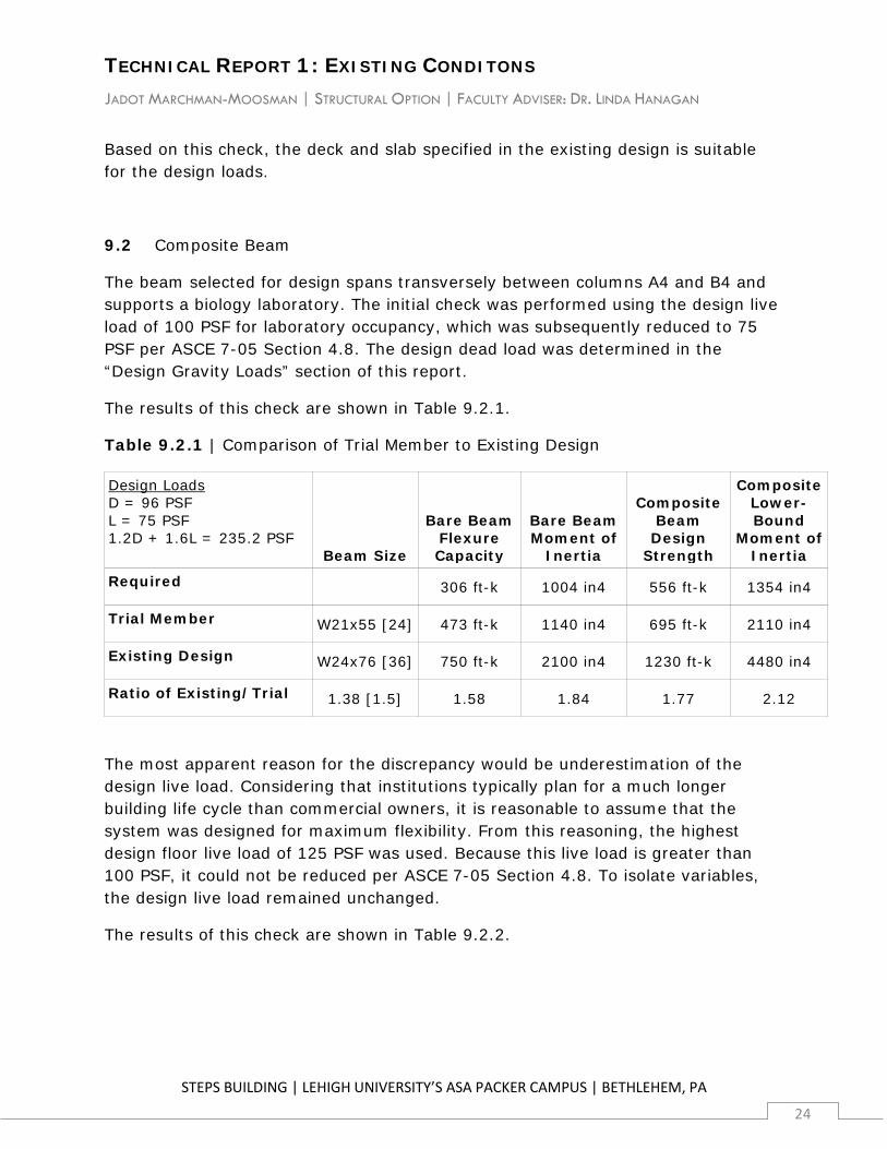
Based on this check, the deck and slab specified in the existing design is suitable for the design loads.
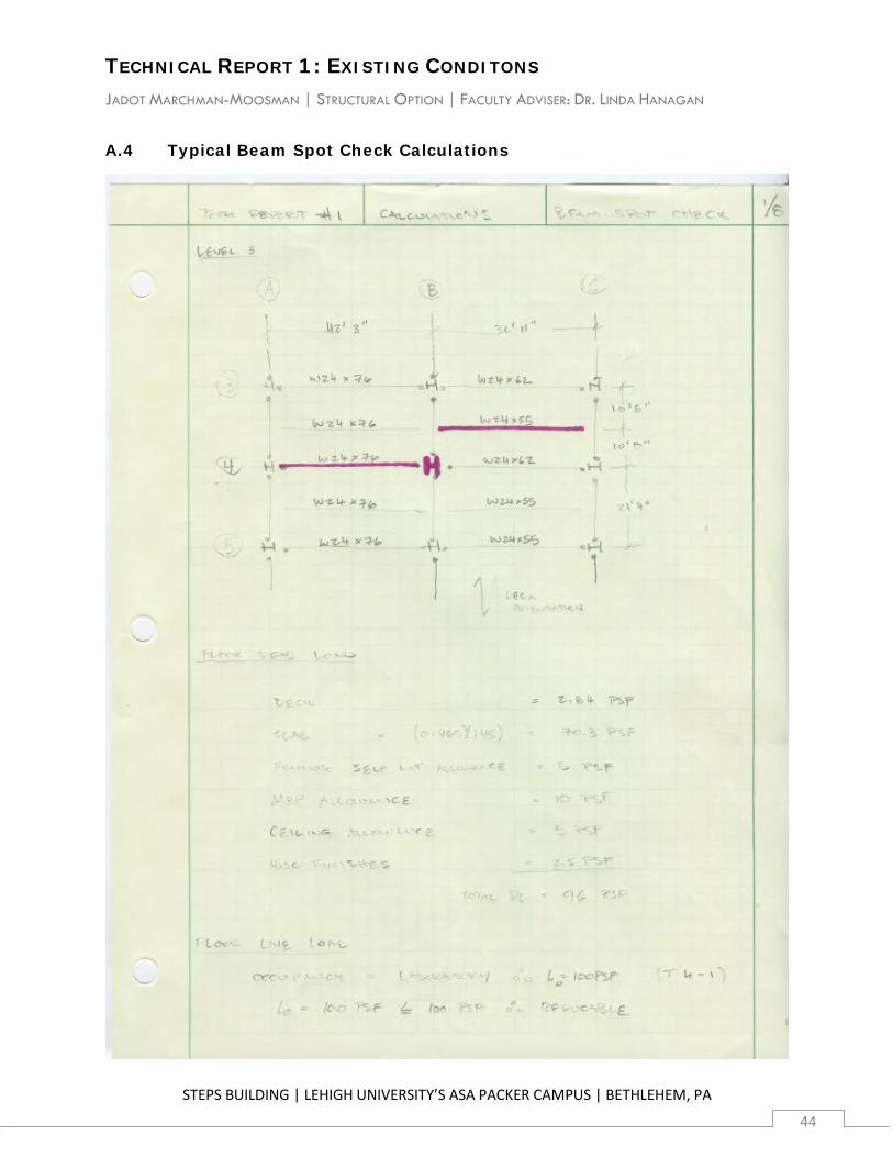
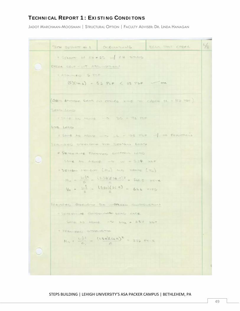
9.2 Composite Beam
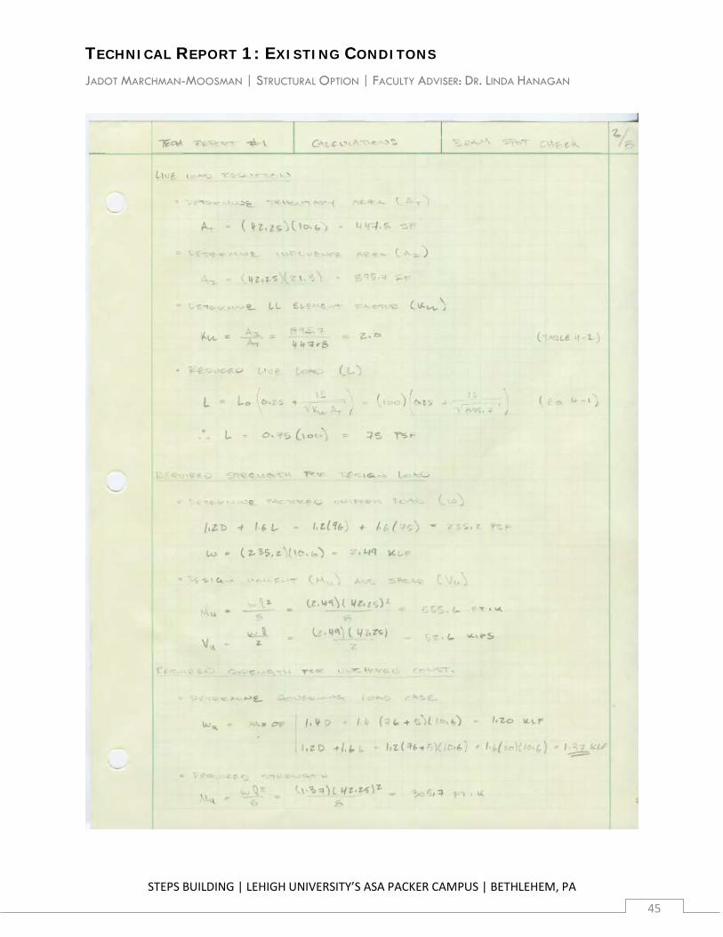
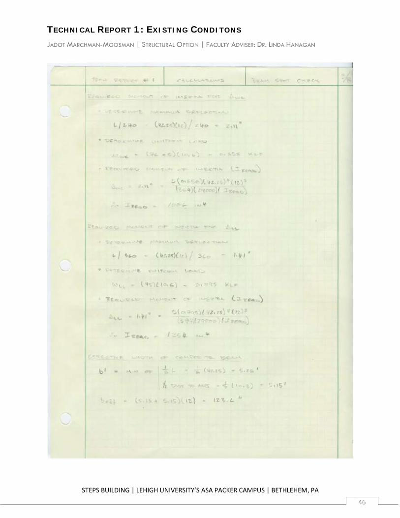
The beam selected for design spans transversely between columns A4 and B4 and supports a biology laboratory. The initial check was performed using the design live load of 100 PSF for laboratory occupancy, which was subsequently reduced to 75 PSF per ASCE 7-05 Section 4.8. The design dead load was determined in the “Design Gravity Loads” section of this report.
The results of this check are shown in Table 9.2.1.
Table 9.2.1 | Comparison of Trial Member to Existing Design
Design Loads D = 96 PSF L = 75 PSF 1.2D + 1.6L = 235.2 PSF
Beam Size
Bare Beam Flexure Capacity
Bare Beam Moment of
Inertia
Composite Beam
Design Strength
Composite Lower-Bound
Moment of Inertia
Required 306 ft-k 1004 in4 556 ft-k 1354 in4
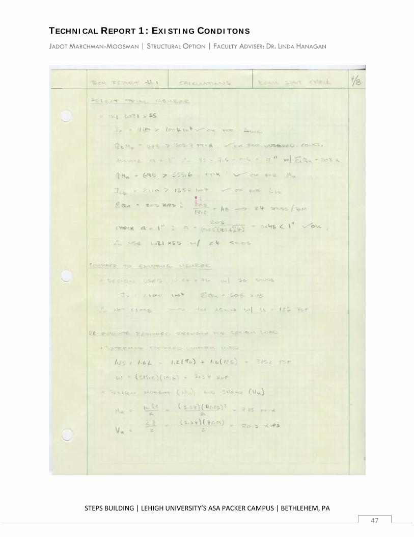
Trial Member W21x55 [24] 473 ft-k 1140 in4 695 ft-k 2110 in4
Existing Design W24x76 [36] 750 ft-k 2100 in4 1230 ft-k 4480 in4
Ratio of Existing/Trial 1.38 [1.5] 1.58 1.84 1.77 2.12
The most apparent reason for the discrepancy would be underestimation of the design live load. Considering that institutions typically plan for a much longer building life cycle than commercial owners, it is reasonable to assume that the system was designed for maximum flexibility. From this reasoning, the highest design floor live load of 125 PSF was used. Because this live load is greater than 100 PSF, it could not be reduced per ASCE 7-05 Section 4.8. To isolate variables, the design live load remained unchanged.
The results of this check are shown in Table 9.2.2.

TECHNICAL REPORT 1: EXISTING CONDITONS JADOT MARCHMAN-MOOSMAN | STRUCTURAL OPTION | FACULTY ADVISER: DR. LINDA HANAGAN
STEPS BUILDING | LEHIGH UNIVERSITY’S ASA PACKER CAMPUS | BETHLEHEM, PA
25
Table 9.2.2 | Comparison of Trial Member to Existing Design
Design Loads D = 96 PSF L = 125 PSF 1.2D + 1.6L = 315.2 PSF
Beam Size
Bare Beam Flexure Capacity
Bare Beam Moment of
Inertia
Composite Beam
Design Strength
Composite Lower-Bound
Moment of Inertia
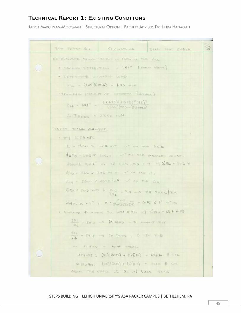
Required 306 ft-k 1004 in4 745 ft-k 2332 in4
Trial Member W24x55 [24] 503 ft-k 1350 in4 865 ft-k 2500 in4
Existing Design W24x76 [36] 750 ft-k 2100 in4 1230 ft-k 4480 in4
Ratio of Existing/Trial 1.38 [1.5] 1.49 1.55 1.42 1.79
To troubleshoot this result, a second location was then checked. The new member also spans transversely, but on the opposite side of the building between columns B4 and C4. The beam supports graduate student offices, rests on longitudinal girders, and does not participate in the flexible moment frame system.
Selecting a beam that is not framed into columns and in a different occupancy area was hoped to determine whether the member size mis-match was driven either by 1) an unaccounted-for aspect of the lateral system, or 2) additional strength or serviceability requirements in the area of the first member. If the trial member were substantially oversized, it would suggest that the former is true, and the live load assumption was a false lead. If the trial member were close to the existing design, it would suggest that the latter is true and the live load assumption was appropriate. If the trial member were undersized by a ratio similar to that of the second trial member, it would suggest that the same unknown load conditions exist throughout the building.
The results of this check are shown in Table 9.2.3.
Table 9.2.3 | Comparison of Trial Member to Existing Design
TECHNICAL REPORT 1: EXISTING CONDITONS JADOT MARCHMAN-MOOSMAN | STRUCTURAL OPTION | FACULTY ADVISER: DR. LINDA HANAGAN
STEPS BUILDING | LEHIGH UNIVERSITY’S ASA PACKER CAMPUS | BETHLEHEM, PA
26
Design Loads D = 96 PSF L = 125 PSF 1.2D + 1.6L = 315.2 PSF
Beam Size
Bare Beam Flexure Capacity
Bare Beam Moment of
Inertia
Composite Beam
Design Strength
Composite Lower-Bound
Moment of Inertia
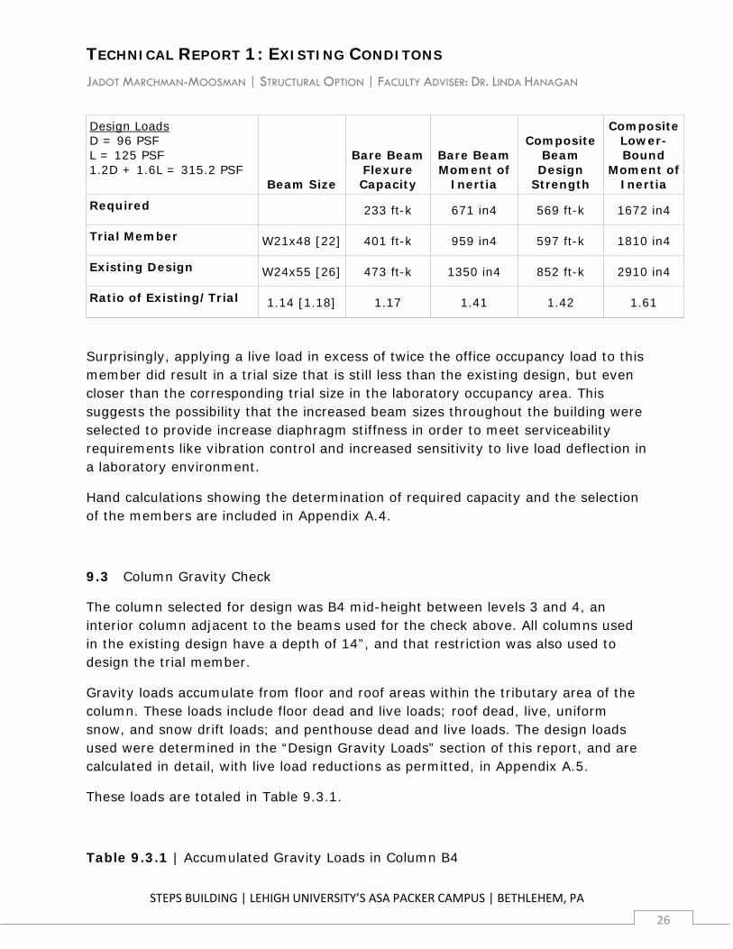
Required 233 ft-k 671 in4 569 ft-k 1672 in4
Trial Member W21x48 [22] 401 ft-k 959 in4 597 ft-k 1810 in4
Existing Design W24x55 [26] 473 ft-k 1350 in4 852 ft-k 2910 in4
Ratio of Existing/Trial 1.14 [1.18] 1.17 1.41 1.42 1.61
Surprisingly, applying a live load in excess of twice the office occupancy load to this member did result in a trial size that is still less than the existing design, but even closer than the corresponding trial size in the laboratory occupancy area. This suggests the possibility that the increased beam sizes throughout the building were selected to provide increase diaphragm stiffness in order to meet serviceability requirements like vibration control and increased sensitivity to live load deflection in a laboratory environment.
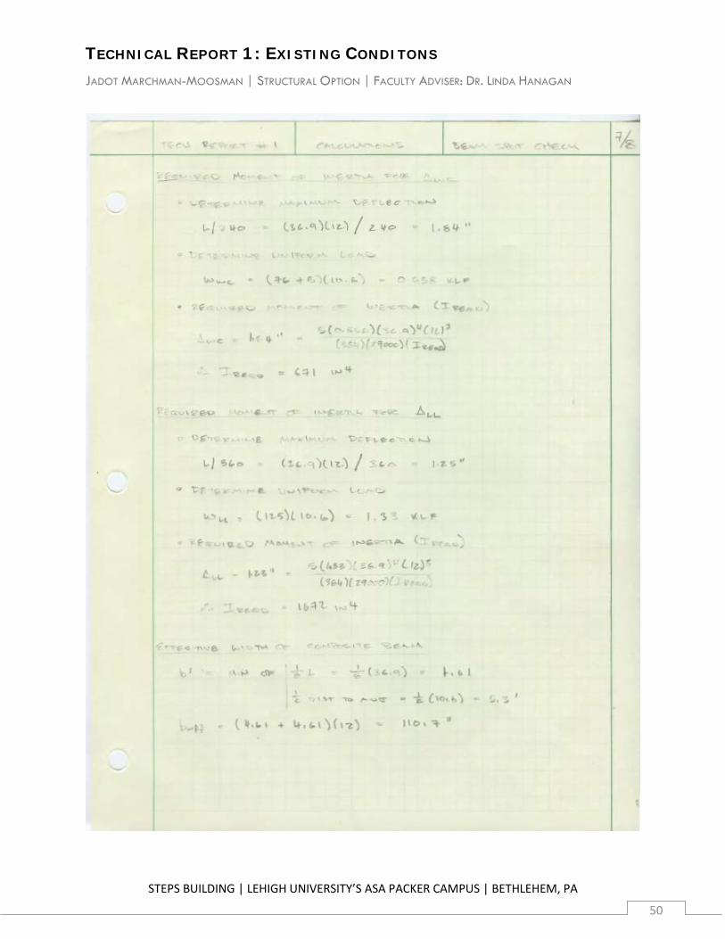
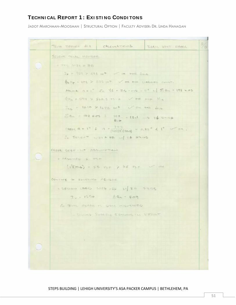
Hand calculations showing the determination of required capacity and the selection of the members are included in Appendix A.4.
9.3 Column Gravity Check
The column selected for design was B4 mid-height between levels 3 and 4, an interior column adjacent to the beams used for the check above. All columns used in the existing design have a depth of 14”, and that restriction was also used to design the trial member.
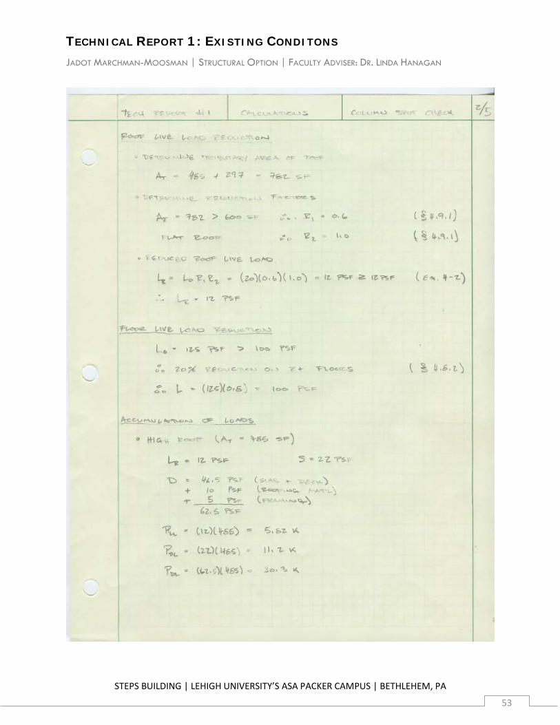
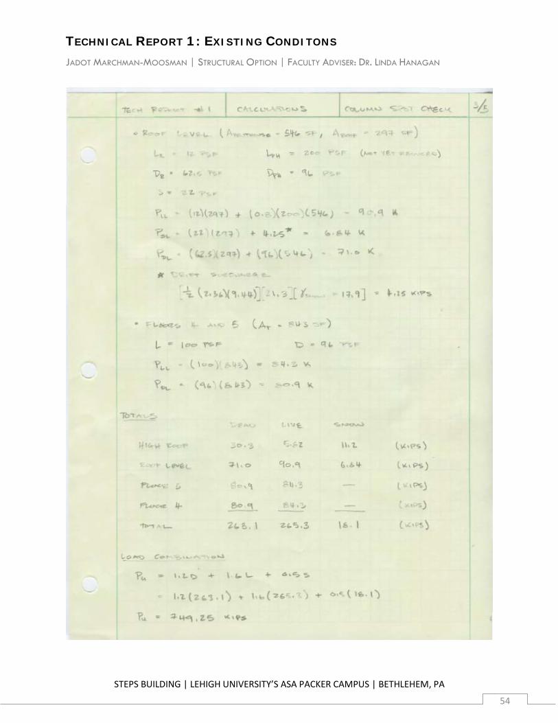
Gravity loads accumulate from floor and roof areas within the tributary area of the column. These loads include floor dead and live loads; roof dead, live, uniform snow, and snow drift loads; and penthouse dead and live loads. The design loads used were determined in the “Design Gravity Loads” section of this report, and are calculated in detail, with live load reductions as permitted, in Appendix A.5.
These loads are totaled in Table 9.3.1.
Table 9.3.1 | Accumulated Gravity Loads in Column B4
TECHNICAL REPORT 1: EXISTING CONDITONS JADOT MARCHMAN-MOOSMAN | STRUCTURAL OPTION | FACULTY ADVISER: DR. LINDA HANAGAN
STEPS BUILDING | LEHIGH UNIVERSITY’S ASA PACKER CAMPUS | BETHLEHEM, PA
27
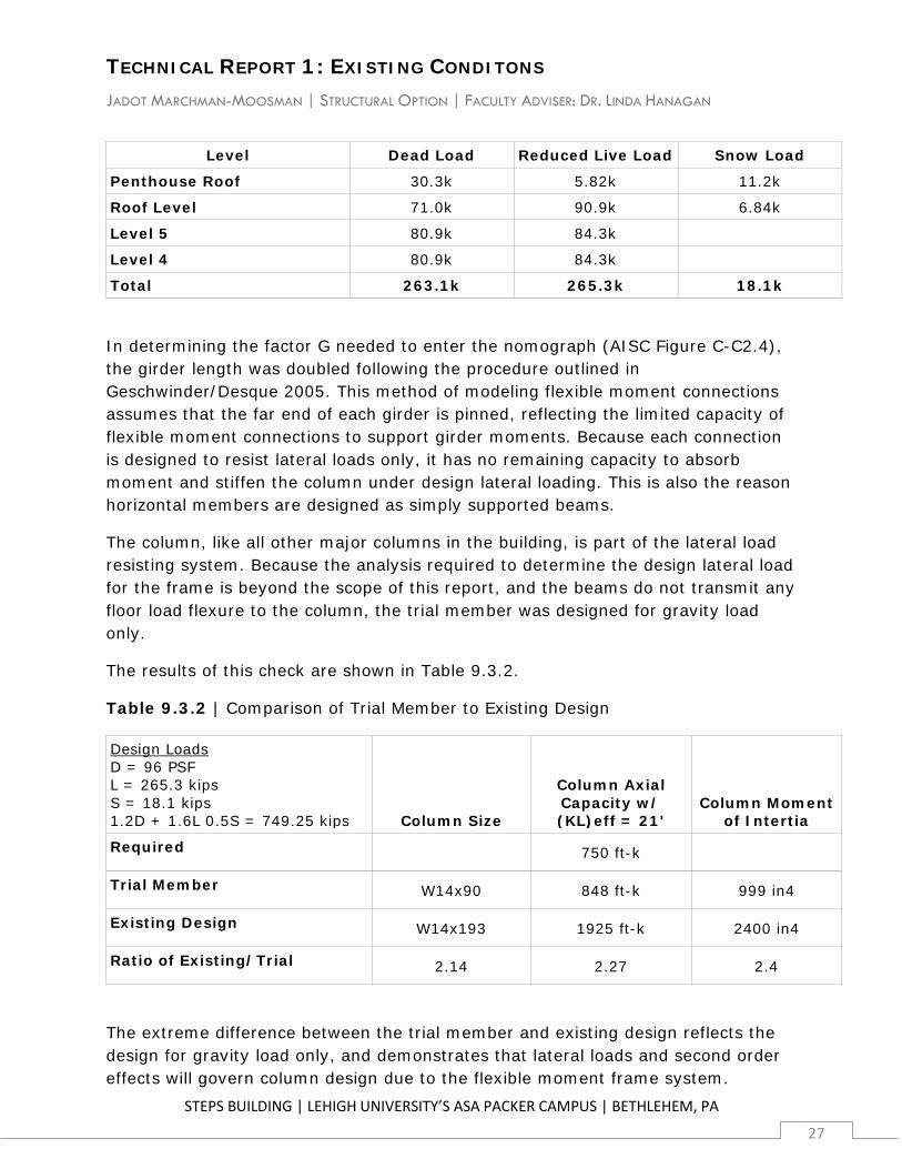
Level Dead Load Reduced Live Load Snow Load
Penthouse Roof 30.3k 5.82k 11.2k
Roof Level 71.0k 90.9k 6.84k
Level 5 80.9k 84.3k
Level 4 80.9k 84.3k
Total 263.1k 265.3k 18.1k
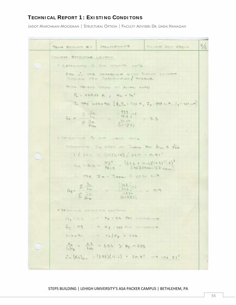
In determining the factor G needed to enter the nomograph (AISC Figure C-C2.4), the girder length was doubled following the procedure outlined in Geschwinder/Desque 2005. This method of modeling flexible moment connections assumes that the far end of each girder is pinned, reflecting the limited capacity of flexible moment connections to support girder moments. Because each connection is designed to resist lateral loads only, it has no remaining capacity to absorb moment and stiffen the column under design lateral loading. This is also the reason horizontal members are designed as simply supported beams.
The column, like all other major columns in the building, is part of the lateral load resisting system. Because the analysis required to determine the design lateral load for the frame is beyond the scope of this report, and the beams do not transmit any floor load flexure to the column, the trial member was designed for gravity load only.
The results of this check are shown in Table 9.3.2.
Table 9.3.2 | Comparison of Trial Member to Existing Design
Design Loads D = 96 PSF L = 265.3 kips S = 18.1 kips 1.2D + 1.6L 0.5S = 749.25 kips Column Size
Column Axial Capacity w/ (KL)eff = 21'
Column Moment of Intertia
Required 750 ft-k
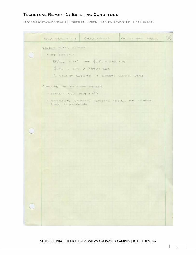
Trial Member W14x90 848 ft-k 999 in4
Existing Design W14x193 1925 ft-k 2400 in4
Ratio of Existing/Trial 2.14 2.27 2.4
The extreme difference between the trial member and existing design reflects the design for gravity load only, and demonstrates that lateral loads and second order effects will govern column design due to the flexible moment frame system.
TECHNICAL REPORT 1: EXISTING CONDITONS JADOT MARCHMAN-MOOSMAN | STRUCTURAL OPTION | FACULTY ADVISER: DR. LINDA HANAGAN
STEPS BUILDING | LEHIGH UNIVERSITY’S ASA PACKER CAMPUS | BETHLEHEM, PA
28
Hand calculations showing the determination of required capacity and the selection of a member are included in Appendix A.5.
A.1 Design Snow Load Calculations
TECHNICAL REPORT 1: EXISTING CONDITONS JADOT MARCHMAN-MOOSMAN | STRUCTURAL OPTION | FACULTY ADVISER: DR. LINDA HANAGAN
STEPS BUILDING | LEHIGH UNIVERSITY’S ASA PACKER CAMPUS | BETHLEHEM, PA
29
TECHNICAL REPORT 1: EXISTING CONDITONS JADOT MARCHMAN-MOOSMAN | STRUCTURAL OPTION | FACULTY ADVISER: DR. LINDA HANAGAN
STEPS BUILDING | LEHIGH UNIVERSITY’S ASA PACKER CAMPUS | BETHLEHEM, PA
30
TECHNICAL REPORT 1: EXISTING CONDITONS JADOT MARCHMAN-MOOSMAN | STRUCTURAL OPTION | FACULTY ADVISER: DR. LINDA HANAGAN
STEPS BUILDING | LEHIGH UNIVERSITY’S ASA PACKER CAMPUS | BETHLEHEM, PA
31
A.2 Design Wind Pressure Calculations
TECHNICAL REPORT 1: EXISTING CONDITONS JADOT MARCHMAN-MOOSMAN | STRUCTURAL OPTION | FACULTY ADVISER: DR. LINDA HANAGAN
STEPS BUILDING | LEHIGH UNIVERSITY’S ASA PACKER CAMPUS | BETHLEHEM, PA
32
TECHNICAL REPORT 1: EXISTING CONDITONS JADOT MARCHMAN-MOOSMAN | STRUCTURAL OPTION | FACULTY ADVISER: DR. LINDA HANAGAN
STEPS BUILDING | LEHIGH UNIVERSITY’S ASA PACKER CAMPUS | BETHLEHEM, PA
33
TECHNICAL REPORT 1: EXISTING CONDITONS JADOT MARCHMAN-MOOSMAN | STRUCTURAL OPTION | FACULTY ADVISER: DR. LINDA HANAGAN
STEPS BUILDING | LEHIGH UNIVERSITY’S ASA PACKER CAMPUS | BETHLEHEM, PA
34
TECHNICAL REPORT 1: EXISTING CONDITONS JADOT MARCHMAN-MOOSMAN | STRUCTURAL OPTION | FACULTY ADVISER: DR. LINDA HANAGAN
STEPS BUILDING | LEHIGH UNIVERSITY’S ASA PACKER CAMPUS | BETHLEHEM, PA
35
TECHNICAL REPORT 1: EXISTING CONDITONS JADOT MARCHMAN-MOOSMAN | STRUCTURAL OPTION | FACULTY ADVISER: DR. LINDA HANAGAN
STEPS BUILDING | LEHIGH UNIVERSITY’S ASA PACKER CAMPUS | BETHLEHEM, PA
36
TECHNICAL REPORT 1: EXISTING CONDITONS JADOT MARCHMAN-MOOSMAN | STRUCTURAL OPTION | FACULTY ADVISER: DR. LINDA HANAGAN
STEPS BUILDING | LEHIGH UNIVERSITY’S ASA PACKER CAMPUS | BETHLEHEM, PA
37
TECHNICAL REPORT 1: EXISTING CONDITONS JADOT MARCHMAN-MOOSMAN | STRUCTURAL OPTION | FACULTY ADVISER: DR. LINDA HANAGAN
STEPS BUILDING | LEHIGH UNIVERSITY’S ASA PACKER CAMPUS | BETHLEHEM, PA
38
A.3 Design Seismic Load Calculations
TECHNICAL REPORT 1: EXISTING CONDITONS JADOT MARCHMAN-MOOSMAN | STRUCTURAL OPTION | FACULTY ADVISER: DR. LINDA HANAGAN
STEPS BUILDING | LEHIGH UNIVERSITY’S ASA PACKER CAMPUS | BETHLEHEM, PA
39
TECHNICAL REPORT 1: EXISTING CONDITONS JADOT MARCHMAN-MOOSMAN | STRUCTURAL OPTION | FACULTY ADVISER: DR. LINDA HANAGAN
STEPS BUILDING | LEHIGH UNIVERSITY’S ASA PACKER CAMPUS | BETHLEHEM, PA
40
TECHNICAL REPORT 1: EXISTING CONDITONS JADOT MARCHMAN-MOOSMAN | STRUCTURAL OPTION | FACULTY ADVISER: DR. LINDA HANAGAN
STEPS BUILDING | LEHIGH UNIVERSITY’S ASA PACKER CAMPUS | BETHLEHEM, PA
41
TECHNICAL REPORT 1: EXISTING CONDITONS JADOT MARCHMAN-MOOSMAN | STRUCTURAL OPTION | FACULTY ADVISER: DR. LINDA HANAGAN
STEPS BUILDING | LEHIGH UNIVERSITY’S ASA PACKER CAMPUS | BETHLEHEM, PA
42
TECHNICAL REPORT 1: EXISTING CONDITONS JADOT MARCHMAN-MOOSMAN | STRUCTURAL OPTION | FACULTY ADVISER: DR. LINDA HANAGAN
STEPS BUILDING | LEHIGH UNIVERSITY’S ASA PACKER CAMPUS | BETHLEHEM, PA
43
TECHNICAL REPORT 1: EXISTING CONDITONS JADOT MARCHMAN-MOOSMAN | STRUCTURAL OPTION | FACULTY ADVISER: DR. LINDA HANAGAN
STEPS BUILDING | LEHIGH UNIVERSITY’S ASA PACKER CAMPUS | BETHLEHEM, PA
44
A.4 Typical Beam Spot Check Calculations
TECHNICAL REPORT 1: EXISTING CONDITONS JADOT MARCHMAN-MOOSMAN | STRUCTURAL OPTION | FACULTY ADVISER: DR. LINDA HANAGAN
STEPS BUILDING | LEHIGH UNIVERSITY’S ASA PACKER CAMPUS | BETHLEHEM, PA
45
TECHNICAL REPORT 1: EXISTING CONDITONS JADOT MARCHMAN-MOOSMAN | STRUCTURAL OPTION | FACULTY ADVISER: DR. LINDA HANAGAN
STEPS BUILDING | LEHIGH UNIVERSITY’S ASA PACKER CAMPUS | BETHLEHEM, PA
46
TECHNICAL REPORT 1: EXISTING CONDITONS JADOT MARCHMAN-MOOSMAN | STRUCTURAL OPTION | FACULTY ADVISER: DR. LINDA HANAGAN
STEPS BUILDING | LEHIGH UNIVERSITY’S ASA PACKER CAMPUS | BETHLEHEM, PA
47
TECHNICAL REPORT 1: EXISTING CONDITONS JADOT MARCHMAN-MOOSMAN | STRUCTURAL OPTION | FACULTY ADVISER: DR. LINDA HANAGAN
STEPS BUILDING | LEHIGH UNIVERSITY’S ASA PACKER CAMPUS | BETHLEHEM, PA
48
TECHNICAL REPORT 1: EXISTING CONDITONS JADOT MARCHMAN-MOOSMAN | STRUCTURAL OPTION | FACULTY ADVISER: DR. LINDA HANAGAN
STEPS BUILDING | LEHIGH UNIVERSITY’S ASA PACKER CAMPUS | BETHLEHEM, PA
49
TECHNICAL REPORT 1: EXISTING CONDITONS JADOT MARCHMAN-MOOSMAN | STRUCTURAL OPTION | FACULTY ADVISER: DR. LINDA HANAGAN
STEPS BUILDING | LEHIGH UNIVERSITY’S ASA PACKER CAMPUS | BETHLEHEM, PA
50
TECHNICAL REPORT 1: EXISTING CONDITONS JADOT MARCHMAN-MOOSMAN | STRUCTURAL OPTION | FACULTY ADVISER: DR. LINDA HANAGAN
STEPS BUILDING | LEHIGH UNIVERSITY’S ASA PACKER CAMPUS | BETHLEHEM, PA
51
TECHNICAL REPORT 1: EXISTING CONDITONS JADOT MARCHMAN-MOOSMAN | STRUCTURAL OPTION | FACULTY ADVISER: DR. LINDA HANAGAN
STEPS BUILDING | LEHIGH UNIVERSITY’S ASA PACKER CAMPUS | BETHLEHEM, PA
52
A.6 Typical Column Spot Check Calculations
TECHNICAL REPORT 1: EXISTING CONDITONS JADOT MARCHMAN-MOOSMAN | STRUCTURAL OPTION | FACULTY ADVISER: DR. LINDA HANAGAN
STEPS BUILDING | LEHIGH UNIVERSITY’S ASA PACKER CAMPUS | BETHLEHEM, PA
53
TECHNICAL REPORT 1: EXISTING CONDITONS JADOT MARCHMAN-MOOSMAN | STRUCTURAL OPTION | FACULTY ADVISER: DR. LINDA HANAGAN
STEPS BUILDING | LEHIGH UNIVERSITY’S ASA PACKER CAMPUS | BETHLEHEM, PA
54
TECHNICAL REPORT 1: EXISTING CONDITONS JADOT MARCHMAN-MOOSMAN | STRUCTURAL OPTION | FACULTY ADVISER: DR. LINDA HANAGAN
STEPS BUILDING | LEHIGH UNIVERSITY’S ASA PACKER CAMPUS | BETHLEHEM, PA
55
TECHNICAL REPORT 1: EXISTING CONDITONS JADOT MARCHMAN-MOOSMAN | STRUCTURAL OPTION | FACULTY ADVISER: DR. LINDA HANAGAN
STEPS BUILDING | LEHIGH UNIVERSITY’S ASA PACKER CAMPUS | BETHLEHEM, PA
56