Embed Size (px)
Citation preview
NIPPON STEEL TECHNICAL REPORT No. 104 AUGUST 2013
- 62 -
1. IntroductionElectromagnetic casting (EMC) is an improved version of con-
tinuous casting in which an electromagnetic field is applied to the initially solidified shell right under the meniscus of the molten steel within the mold. With this technology, it should become possible to control the phenomenon of initial solidification of molten steel and thereby improve the surface qualities of cast slab.1)
The Nippon Steel Corporation proposed pulsative electromag-netic casting (pulsative EMC) to further improve the surface quali-ties of cast slab through intermittent application of an electromag-netic field.2, 3) The company has already carried out a series of cast-ing tests using an experimental continuous billet caster and a plant continuous billet caster and has demonstrated that EMC significant-ly improves the surface qualities of cast billet and makes it possible to omit the surface conditioning of billets before they are rolled into final products.4-7) In casting tests of small-section slabs using an ex-perimental continuous slab caster, too, the company has demonstrat-ed that EMC markedly improves the surface qualities of cast slabs.7-10) On the basis of the above test results, we carried out cast-ing tests of large-section slabs using a plant continuous slab cast-er11-13) and developed EMC technology for large-section slabs.
In this report, we shall describe the principles of pulsative EMC technology, the circumstances leading up to development of the technology, and the results of large-section slab casting tests carried out using a plant continuous slab caster.
It should be noted that the contents of the report are partly the results of the “Development of Metal Manufacturing Processes for Rationalizing the Use of Energy” 5-10) carried out by the Japan Re-
search and Development Center for Metals (JRCM) under a subsidy of the former Ministry of International Trade and Industry and the results of the “Development of High-Efficiency Electromagnetic Slab Casting Technology for Saving Energy and Improving Slab Qualities” 11-13) carried out jointly by the New Energy and Industrial Technology Development Organization (NEDO) and Nippon Steel Corporation.
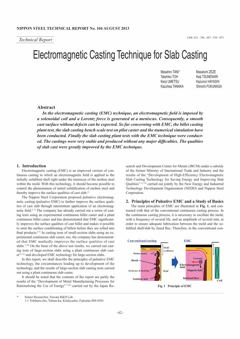
2. Principles of Pulsative EMC and a Study of BasicsThe main principles of EMC are illustrated in Fig. 1, and con-
trasted with that of the conventional continuous casting process. In the continuous casting process, it is necessary to oscillate the mold, with a frequency of several Hz, and an amplitude of several mm, in order to ensure adequate lubrication between the mold and the so-lidified shell/slab by fused flux. Therefore, in the conventional con-
Technical Report UDC 621 . 746 . 047 : 539 : 072
* Senior Researcher, Yawata R&D Lab. 1-1 Tobihata-cho, Tobata-ku, Kitakyushu, Fukuoka 804-8501
Electromagnetic Casting Technique for Slab CastingMasahiro TANI* Masafumi ZEZETakehiko TOH Keiji TSUNENARIKenji UMETSU Kazunori HAYASHIKazuhisa TANAKA Shinichi FUKUNAGA
AbstractIn the electromagnetic casting (EMC) technique, an electromagnetic field is imposed by
a solenoidal coil and a Lorentz force is generated at a meniscus. Consequently, a smooth cast surface without defects can be expected. So far concerning with EMC, the billet casting plant test, the slab casting bench scale test on pilot caster and the numerical simulation have been conducted. Finally the slab casting plant tests with the EMC technique were conduct-ed. The castings were very stable and produced without any major difficulties. The qualities of slab cast were greatly improved by the EMC technique.
Fig. 1 Principle of EMC

NIPPON STEEL TECHNICAL REPORT No. 104 AUGUST 2013
- 63 -
tinuous casting process (left-hand diagram in Fig. 1), the pressure of the fused flux changes cyclically, causing tiny, periodic dents called oscillation marks (hundreds of μm in depth) to be formed on the slab surface at intervals of several mm in the casting direction. In addition, in the case of low carbon steel, a solidified shell tip called a hook (hook-shaped structure) is sometimes observed at the base of individual oscillation marks. Nonmetallic inclusions (hereinafter simply called inclusions) and bubbles entrapped in the hooks can become origins of defects in the slab or product.
On the other hand, in the EMC process (right-hand diagram in Fig. 1), an AC current is passed through a solenoid coil (a coil of wire spirally wound around a cylindrical or rectangular core) in-stalled at a level very close to the surface of the molten steel to gen-erate an induced magnetic field and an induced current in the molten steel and the solidifying shell. By means of the interaction between them (Fleming’s left hand law), an electromagnetic field (Lorentz Force), which is always directed from the mold toward the molten steel, is generated. Then, the molten steel static pressure acting on the molten steel in the initially solidified portion and on the solidi-fied shell decreases, thereby bringing about a “soft contact state” in which the layer of fused flux between the mold and the molten steel increases in thickness.
Under the soft contact state, the periodic change in pressure of the fused flux is restrained and the initially solidified portion is cooled slowly. In addition, as the solidified shell is cleaned by the molten steel flow induced by the electromagnetic field as shown in the right-hand diagram of Fig. 1, the oscillation marks and hooks disappear or decrease in depth markedly and the occurrence of de-fects is restrained. Thus, it can be expected that EMC will signifi-cantly improve the surface qualities of cast slab.1)
However, the original EMC technology had a number of draw-backs. One of them was that the molten steel flow induced by the electromagnetic field was so rapid that the meniscus of molten steel became unstable and irregular in terms of time and space, making it impossible to maintain a stable soft contact state in the casting di-rection or in the mold circumferential direction. Therefore, EMC did not always offer better surface qualities of cast slab.
As a means of alleviating this drawback, the Nippon Steel Cor-poration developed a new technology named pulsative electromag-netic casting (pulsative EMC).2, 3) In pulsative EMC, an electromag-netic field is applied intermittently to the molten steel in the initially solidified portion and to the solidified shell by passing an AC cur-rent through a solenoid coil at a frequency of several to tens of Hz. By so doing, it is possible to control the velocity of the molten steel flow induced by the electromagnetic field.
Fig. 2 describes the results of a basic pulsative EMC experiment, carried out using mercury. A 200 Hz AC current was intermittently passed through a solenoid coil installed around a glass beaker filled with mercury.
In the experiment, the convex height of the meniscus of the mer-cury caused by the electromagnetic field—the index of “soft contact state”—and the magnitude of the velocity of mercury flow induced by the electromagnetic field were measured as a function of the pa-rameter of intermittent current application, duty, defined by the fol-lowing equation
Duty = ton / T × 100 (%) (1)where T is the intermittent current application period (conduction time + non-conduction time) and ton is the conduction time. It can be seen from Fig. 2 that the relationship between induced velocity and duty is linear but that the relationship between convex height and
duty is nonlinear. The implication is that by intermittently applying an electromagnetic field at duty = 50%, it is possible to secure a convex height of approximately 90% while restraining the induced velocity to 50%. It is generally accepted that a stable soft contact state will be maintained when the surface profile (molten steel me-niscus) is kept stable.2, 3)
Next, a numerical simulation of the flow of molten steel and the behavior of the molten steel meniscus, during pulsative EMC, was carried out through the coupling of an electromagnetic field analysis with a molten steel flow analysis, where the molten steel is treated as a free surface,14) on a system composed of a solenoid coil, molten steel, and mold. Fig. 3 shows an example of the results of the simu-lation for the EMC of billet. It can be seen that the free surface shape of the molten steel in the mold circumferential direction is ir-regular when the electromagnetic field was applied continuously, whereas the free surface shape of the molten steel in the mold cir-cumferential direction is regular when the electromagnetic field was applied intermittently (duty = 50%).7)
3. Casting Tests Using a Plant Continuous Billet CasterFollowing preliminary studies based on the results of the basic
experiments and numerical simulation described in the preceding section, and after the subsequent casting tests of low melting point
Fig. 2 Pulsative imposition of electromagnetic field
(a) Continuous imposition (b) Pulsative imposition
Fig. 3 Free surface shape of molten steel

NIPPON STEEL TECHNICAL REPORT No. 104 AUGUST 2013
- 64 -
alloy and steel using an experimental continuous billet caster,4, 5) a pulsative EMC test was carried out using a plant continuous billet caster at Muroran Works of the Nippon Steel Corporation.6, 7)
For test purposes, one of the streams of Muroran›s 6-stream con-tinuous billet caster was provided with a solenoid coil and a special-ly constructed, 160-mm-square mold for use with pulsative EMC technology. The mold was fabricated from four pairs of copper plates and fashioned with a stainless steel back plate, which allowed for both mechanical rigidity and sufficient penetration of the elec-tromagnetic field into the molten steel.
In pulsative EMC, a large induced magnetic field is generated near the meniscus of the molten steel, and the induced magnetic field interferes with proper functionality of the eddy current sensor that is commonly used in controlling the molten steel bath level (molten steel pouring rate). Therefore, we developed an eddy cur-rent bath level sensor that is synchronized with the pulsative electro-magnetic field. The principle of operation of the sensor is shown in Fig. 4. With this system, molten steel bath levels are sampled using a signal from the eddy current sensor while the AC current is not passed through the solenoid coil, that is, while the electromagnetic field is not applied to the molten steel.
Using the solenoid coil, mold, and pulse-synchronized eddy cur-rent sensor developed for pulsative EMC, we carried out a pulsative EMC test on the plant continuous billet caster. With the exception of the intermittent application of an electromagnetic field, the same casting conditions were applied to all six streams of the continuous caster. It was found that the pulsative EMC operation could be per-formed stably for many hours without any adverse effect on the control of the molten steel bath level, etc.
Fig. 5 shows the difference in normalized mold flux consump-tion with and without pulsative EMC. It can be seen that pulsative EMC increases the consumption of mold flux. The observed in-crease is reasonably accounted for by assuming that the intermittent application of an electromagnetic field widens the gap between the mold and the solidified shell in the initially solidified portion. The implication is that pulsative EMC improves the lubrication between the mold and the solidified shell.
Fig. 6 shows the appearances of billets of 0.08% carbon steel obtained by the test. It was confirmed that the oscillation marks in the casting direction had almost disappeared for billets produced by the pulsative EMC process. Fig. 7 shows the surface roughness of cast billets measured using a laser displacement meter. It can be seen from the figure that the pulsative EMC process reduced the surface roughness of cast billet.
Fig. 8 shows the incidence of defects in each of the products ob-tained by rolling a billet cast by pulsative EMC and a billet cast by the conventional casting process. The vertical axis represents the normalized incidence of defects in product obtained by rolling a bil-let cast by the conventional casting process without hot scarfing. It can be seen from the figure that, even without hot scarfing, the billet obtained by pulsative EMC offers a product quality equal or superi-or to that offered by the billet obtained by the conventional casting
Fig. 4 Meniscus level sensing synchronized to pulsative electromagnetic field
Fig. 5 Mold flux consumption
Fig. 6 Surface appearance of cast billet (0.08%C steel)
Fig. 7 Surface roughness of cast billet (0.08%C steel)

NIPPON STEEL TECHNICAL REPORT No. 104 AUGUST 2013
- 65 -
process with hot scarfing. Thus, it is evident from this data that hot scarfing of billets could possibly be omitted by employing pulsative EMC.
4. Casting Test of Small-Section Slab Using an Experimental Continuous Slab CasterWith the basic technology for pulsative EMC of billet estab-
lished, development of pulsative EMC technology for slab was then pursued. A casting test of small-section slab was initially conducted using an experimental continuous slab caster within Kimitsu Works of the Nippon Steel Corporation.7-10) For the purposes of the test, the 8 m-long experimental vertical type continuous caster was provided with a solenoid coil and specially constructed molds designed for use with pulsative EMC technology as shown in Fig. 9. The inside dimensions of the molds were 400 mm × 100 mm and 800 mm × 100 mm. Each of the molds was fabricated from four pairs of cop-per plates and fashioned with a stainless steel back plate that al-lowed for both mechanical rigidity and for sufficient penetration of the electromagnetic field into the molten steel. The molten steel bath level was controlled using the eddy current bath level sensor syn-chronized with the pulsative electromagnetic field described previ-ously.
Fig. 10 shows the surface of a low-carbon Al-killed steel slab obtained by the pulsative EMC process. It was confirmed that the oscillation marks in the casting direction had almost disappeared for slab produced by this process. Fig. 11 shows the under-skin solidi-fied structures of slabs obtained with and without pulsative EMC. It can be seen that the pulsative EMC process markedly reduced the depths of oscillation marks on the slab surface and the depths of hooks under the skin. Fig. 12 shows the surface roughness of slabs measured by a laser displacement meter. Consideration of Figs. 7 and 12 indicate that, even in the casting of small-section slab that
uses a mold having a larger cross-sectional area than that for billets, the surface property of slab can be improved in almost the same de-
Fig. 8 Number of defects (0.1%C steel)
Fig. 9 Mold and coil for pulsative EMC
Fig. 10 Surface appearance of cast slab (0.2%C steel)
Fig. 11 Solidified structure of cast slab (0.2%C steel)
Fig. 12 Surface roughness of cast slab (0.2%C steel)

NIPPON STEEL TECHNICAL REPORT No. 104 AUGUST 2013
- 66 -
gree as that for billet by intermittently applying an electromagnetic field to the molten steel.
Fig. 13 shows the number of inclusions 100 μm and more in size found in the cast slab by gradually cutting the slab to a depth of 10 mm from the surface. It can be seen that the pulsative EMC process markedly reduced the inclusions in the surface layer of the cast slab. There are two conceivable reasons for this observation. One is that the depth of hooks under the skin of the slab decreased, making it difficult for inclusions to be captured in the slab. The other is that the molten steel flow induced by the electromagnetic field had the effect of cleaning the solidified shell.
Fig. 14 shows the cooling rate of the initially solidified shell cal-culated from the spacing between dendrite arms under the skin of the slab. It can be seen that the pulsative EMC process reduced the cooling rate by 70% to 80%. The observed decrease is reasonably accounted for by assuming that the electromagnetic field widened the distance between the mold and the solidified shell and thereby caused the thermal resistance of the initially solidified shell to in-crease, bringing about a slow-cooling condition.
5. Casting Tests Using a Plant Continuous Slab CasterIn the experimental casting tests of small-section slabs described
above, it was confirmed that pulsative EMC technology helped im-prove the surface qualities of cast slab. As an extension of this work, pulsative EMC tests were carried out using the plant continuous slab caster at Yawata Works of the Nippon Steel Corporation.11-13)
Initially, to examine the proposed modifications to this casting process, an electromagnetic field analysis was conducted, taking into consideration the solenoid coil, molten steel, mold, and periph-eral structure. In conjunction with the field analysis, a numerical simulation of the molten steel flow and meniscus in the mold was conducted, taking into consideration the fused flux and molten steel
free surface, along with a structural analysis of the mold. In light of the above examination, a new power supply, solenoid coil, and a mold designed specially for pulsative EMC technology measuring 1,200 - 1,600 mm × 250 mm, were fabricated to implement pulsative EMC of full-sized slabs on the continuous caster.
Fig. 15 shows an example of results of the numerical simulation of the molten steel flow and meniscus in the mold described above. These results confirm that a uniform molten steel meniscus across the width of the mold and a uniform molten steel flow along the mold walls across the width of the mold can be obtained under the conditions of pulsative EMC even for a large cross section slab (1,280 mm × 250 mm). Fig. 16 shows an example of the results of the mold structural analysis during the casting process. It can be seen that the amount of mold deformation for pulsative EMC during the casting operation is no more than that for an ordinary mold in a conventional casting process. Fig. 17 shows an example of results of the calculation and measurement of the vertical magnetic flux density in the mold during pulsative EMC, where Cal refers to the calculated value, Exp to the measured value F, L to the mold wide face, and C to the mold center thickness. It can be confirmed from the figure that, for the pulsative EMC system designed for a slab
Fig. 13 Number of Inclusion at cast slab surface
Fig. 14 Cooling rate at cast slab surface
Fig. 15 Flow pattern of pulsative EMC
Fig. 16 Deformation of mold for pulsative EMC
Fig. 17 Electromagnetic flux density in the mold for pulsative EMC

NIPPON STEEL TECHNICAL REPORT No. 104 AUGUST 2013
- 67 -
having a large cross section (1,600 mm × 250 mm), a uniform mag-netic field distribution can be obtained along the wide face of the mold.
Next, to evaluate the stability of the meniscus of a molten Sn/Pb-based alloy of low melting point, the plant continuous slab caster was equipped with the power supply, solenoid coil, and the mold, developed specially for pulsative EMC, a stainless steel vessel was placed into the mold, the molten alloy poured into the vessel, and an electromagnetic field applied intermittently to the molten alloy. Fig. 18 shows a photo of the meniscus of the alloy during intermittent application of an electromagnetic field. As shown in the figure, a stable, uniform meniscus could be observed across the width of the mold. At first, there was some concern that the induced electromag-netic field in the molten material would result in induction heating and an increase in the temperature of the mold and peripheral struc-ture. However, no increase in temperature was observed.
Finally, using the above described power supply, solenoid coil, and mold for pulsative EMC, we cast low-carbon Al-killed steel slabs measuring 1,200 mm × 250 mm and 1,600 mm × 250 mm. During the casting, the bath level of molten steel was measured with a pulse-synchronized eddy current sensor to automatically control the molten steel pouring rate, and it was observed that the bath level and pouring rate of molten steel could be controlled stably. All in all, the pulsative EMC operation could be performed for many hours on a stable basis like that of the ordinary casting operation.
Concerning the surface qualities of the slabs obtained by the casting test, the depths of oscillation marks on the slab surface were evaluated across the entire slab width. Fig. 19 shows the evaluation results together with those of small-section slabs obtained by the preceding tests, where plant test refers to samples derived from the plant continuous caster and bench-scale test refers to samples de-rived from the experimental continuous caster. These results confirm
that pulsative EMC significantly improves the surface qualities of large-section slabs as effectively as it does for billets and small-sec-tion slabs.
6. ConclusionThrough tests of the pulsative EMC processing of billets, using a
plant continuous caster, and of small-section slabs, using an experi-mental continuous caster, we confirmed that EMC helped in improv-ing the surface qualities of billets and small-section slabs and estab-lished the basic operational parameters for the pulsative EMC process.
We then developed a new power supply, solenoid coil, and mold for casting large-section slab using the pulsative EMC technology and carried out tests for the casting of large-section slab using a plant continuous caster. As a result, we confirmed that pulsative EMC could be applied even to large-section slabs, and that it im-proved the surface qualities of large-section slab as well as was done for the smaller products.
References1) Takeuchi, E. et al.: CAMP-ISIJ. 6 (4), 1125 (1993)2) Toh, T. et al.: CAMP-ISIJ. 8 (1), 215 (1995)3) Toh, T. et al.: ISIJ-Int. 37 (11), 1112 (1997)4) Tani, M. et al.: New Development of Material Processing Utilizing Elec-
tromagnetic Force. The Iron and Steel Institute of Japan, 1999, p. 1135) Tani, M. et al.: CAMP-ISIJ. 12 (1), 51 (1999)6) Tani, M. et al.: CAMP-ISIJ. 13 (4), 815 (2000)7) Tani, M. et al.: CAMP-ISIJ. 15 (4), 831 (2002)8) Tani, M. et al.: CAMP-ISIJ. 14 (12), 163 (2001)9) Tani, M. et al.: CAMP-ISIJ. 14 (4), 890 (2001)
10) Tani, M. et al.: Proc. 4th European Conf. on Continuous Casting. Bir-mingham, 2002, p. 39
11) Tani. M. et al.: Proc. 5th Int. Symposium on Electromagnetic Process of Materials. Sendai, 2006, p. 63
12) Tani, M. et al.: CAMP-ISIJ. 20 (4), 820 (2007)13) Tani, M. et al.: Int. J. Cast Metals Research. 22, 298 (2009)14) Fujisaki, K. et al.: J. Appl. Phys. 83 (11), 6356 (1998)Fig. 18 Experiment with low-melting-point alloy
Fig. 19 Depth of oscillation mark

NIPPON STEEL TECHNICAL REPORT No. 104 AUGUST 2013
- 68 -
Masahiro TANISenior ResearcherYawata R&D Lab.1-1 Tobihata-cho, Tobata-ku, Kitakyushu,Fukuoka 804-8501
Masafumi ZEZEChief Researcher, Dr.Eng.Yawata R&D Lab.
Takehiko TOHChief Researcher, Dr.Mathematical Science & Technology Research Lab.Advanced Technology Research Laboratories
Keiji TSUNENARIManagerPlant Engineering Div.Plant Engineering and Facility Management Center
Kenji UMETSUManagerSystems & Control Engineering Div.Plant Engineering and Facility Management Center
Kazunori HAYASHISenior Researcher, Dr.Eng.Mechanical Engineering Div.Plant Engineering and Facility Management Center
Kazuhisa TANAKAManegerSteelmaking Div.Yawata Works
Shinichi FUKUNAGAManagerSteelmaking Div.Yawata Works


![menu art. or oo 00 FAX 075-746-5086 075-746-5087 https ...menu art. or oo 00 FAX 075-746-5086 075-746-5087 (QR2— F) ] 9 6 • •](https://img.pdfslide.net/doc/110x75/5ffe224c27cf63401d01a73f/menu-art-or-oo-00-fax-075-746-5086-075-746-5087-https-menu-art-or-oo-00-fax.jpg)