Embed Size (px)
Citation preview
NIPPON STEEL & SUMITOMO METAL TECHNICAL REPORT No. 116 SEPTEMbER 2017
- 20 -
1. IntroductionThrough secondary and tertiary work at users' plants, special
steel bars are formed into parts for automotive engines, drive sys-tems, undercarriages and other critical safety parts. Every piece un-dergoes strict inspection throughout the entire process and condi-tioning, where necessary, before shipment from steelworks. Howev-er, the need for cost reduction and product quality enhancement has increased recently as a result of ever tougher competition in the in-ternational market.
In this situation, to improve product quality, the Bar Mill Plant of Yawata Works of Nippon Steel & Sumitomo Metal Corporation renewed the facilities of its bar inspection and finishing lines to raise the processing speed, enhance productivity and improve inspection accuracy. The present paper introduces the following principal as-pects of the revamp: (1) renewal of two-roll straighteners; (2) intro-duction of new ultrasonic internal flaw detectors applying the syn-thetic aperture focusing technique; and (3) introduction of a multi-story automatic product warehouse to minimize quality damage due to product handling.
2. Outlines of bar Finishing ProcessesThe Bar Mill Plant started up in 1979 to produce straight bars
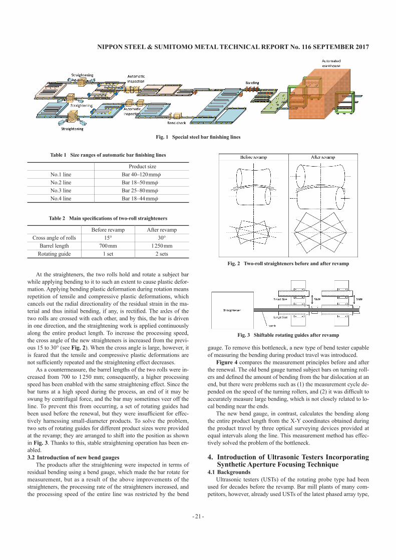
and bars in coil through a fully continuous single-strand rolling mill train. After rolling, straight bars are cooled at the pre-inspection storage, then inspected piece by piece through automatic inspection facilities, and conditioned as required. As seen in Fig. 1, bars are straightened through two-roll straighteners, automatically inspected in terms of surface defects through surface defect detectors and in terms of internal defects by ultrasonic testers (USTs), and the pieces approved as prime products are banded for shipment. The facilities for these processes are arranged in four lines according to the prod-uct size as given in Table 1.
3. Renewal of Two-roll Straighteners3.1 Features of new two-roll straighteners
To satisfy the product straightness requested by users, two-roll straighteners are provided to rectify the product bend arising during cooling after rolling by turning the bars between two rolls, one ar-ranged on the other. Table 2 lists the main specifications of the ma-chines before and after the renewal. The new machines have the fol-lowing two advantages:
1) Markedly higher processing speed; and2) Guiding of bars according to diameter using two rotating
guides of different inner diameters.
Technical Report UDC 621 . 771 . 251 : 620 . 179 . 16
Cost Reduction and Quality Improvement for Bar Inspection and Conditioning
Ryotaro TAKEUCHI* Koichi KOKUBOYoshio UEDA Yusuke KIMURA
AbstractSpecial steel bars undergo secondary and tertiary work at users' plants and are converted
into automotive critical safety parts, and as such, strict inspection and finishing are applied to them, piece by piece, after rolling before shipment. In view of the tough competition in the international market, however, , productivity improvement is urgently required. Against this background, Yawata Works of Nippon Steel & Sumitomo Metal Corporation modernized the product inspection and finishing facilities of the Bar Mill Plant to increase the processing speed and enhance the product quality assurance ability. In addition, a multistory auto-matic product warehouse was built to minimize product damage due to omissible handling. The technologies introduced at the revamp include those commercially applied as the first case in the world; they proved effective at markedly improving the speed and accuracy of product inspection.
* Bar & Wire Rod Rolling Technical Dept., Bar & Wire Rod Div., Yawata Works 1-1 Tobihata-cho, Tobata-ku, Kitakyushu City, Fukuoka Pref. 804-8501
NIPPON STEEL & SUMITOMO METAL TECHNICAL REPORT No. 116 SEPTEMbER 2017
- 21 -
At the straighteners, the two rolls hold and rotate a subject bar while applying bending to it to such an extent to cause plastic defor-mation. Applying bending plastic deformation during rotation means repetition of tensile and compressive plastic deformations, which cancels out the radial directionality of the residual strain in the ma-terial and thus initial bending, if any, is rectified. The axles of the two rolls are crossed with each other, and by this, the bar is driven in one direction, and the straightening work is applied continuously along the entire product length. To increase the processing speed, the cross angle of the new straighteners is increased from the previ-ous 15 to 30° (see Fig. 2). When the cross angle is large, however, it is feared that the tensile and compressive plastic deformations are not sufficiently repeated and the straightening effect decreases.
As a countermeasure, the barrel lengths of the two rolls were in-creased from 700 to 1 250 mm; consequently, a higher processing speed has been enabled with the same straightening effect. Since the bar turns at a high speed during the process, an end of it may be swung by centrifugal force, and the bar may sometimes veer off the line. To prevent this from occurring, a set of rotating guides had been used before the renewal, but they were insufficient for effec-tively harnessing small-diameter products. To solve the problem, two sets of rotating guides for different product sizes were provided at the revamp; they are arranged to shift into the position as shown in Fig. 3. Thanks to this, stable straightening operation has been en-abled.3.2 Introduction of new bend gauges
The products after the straightening were inspected in terms of residual bending using a bend gauge, which made the bar rotate for measurement, but as a result of the above improvements of the straighteners, the processing rate of the straighteners increased, and the processing speed of the entire line was restricted by the bend
gauge. To remove this bottleneck, a new type of bend tester capable of measuring the bending during product travel was introduced.
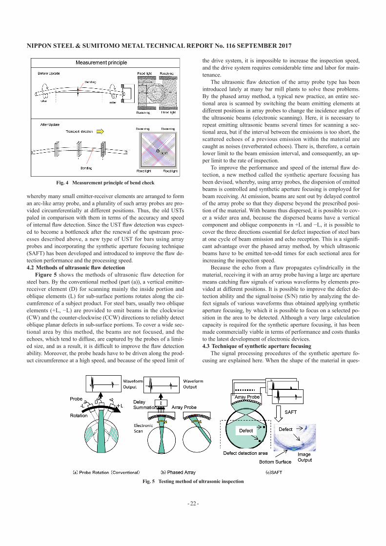
Figure 4 compares the measurement principles before and after the renewal. The old bend gauge turned subject bars on turning roll-ers and defined the amount of bending from the bar dislocation at an end, but there were problems such as (1) the measurement cycle de-pended on the speed of the turning rollers, and (2) it was difficult to accurately measure large bending, which is not closely related to lo-cal bending near the ends.
The new bend gauge, in contrast, calculates the bending along the entire product length from the X-Y coordinates obtained during the product travel by three optical surveying devices provided at equal intervals along the line. This measurement method has effec-tively solved the problem of the bottleneck.
4. Introduction of Ultrasonic Testers Incorporating Synthetic Aperture Focusing Technique
4.1 backgroundsUltrasonic testers (USTs) of the rotating probe type had been
used for decades before the revamp. Bar mill plants of many com-petitors, however, already used USTs of the latest phased array type,
Table 1 Size ranges of automatic bar finishing lines
Product sizeNo.1 line Bar 40–120 mmφNo.2 line Bar 18–50 mmφNo.3 line Bar 25–80 mmφNo.4 line Bar 18–44 mmφ
Table 2 Main specifications of two-roll straighteners
Before revamp After revampCross angle of rolls 15° 30°
Barrel length 700 mm 1 250 mmRotating guide 1 set 2 sets
Fig. 2 Two-roll straighteners before and after revamp
Fig. 3 Shiftable rotating guides after revamp
Fig. 1 Special steel bar finishing lines
NIPPON STEEL & SUMITOMO METAL TECHNICAL REPORT No. 116 SEPTEMbER 2017
- 22 -
whereby many small emitter-receiver elements are arranged to form an arc-like array probe, and a plurality of such array probes are pro-vided circumferentially at different positions. Thus, the old USTs paled in comparison with them in terms of the accuracy and speed of internal flaw detection. Since the UST flaw detection was expect-ed to become a bottleneck after the renewal of the upstream proc-esses described above, a new type of UST for bars using array probes and incorporating the synthetic aperture focusing technique (SAFT) has been developed and introduced to improve the flaw de-tection performance and the processing speed.4.2 Methods of ultrasonic flaw detection
Figure 5 shows the methods of ultrasonic flaw detection for steel bars. By the conventional method (part (a)), a vertical emitter-receiver element (D) for scanning mainly the inside portion and oblique elements (L) for sub-surface portions rotates along the cir-cumference of a subject product. For steel bars, usually two oblique elements (+L, −L) are provided to emit beams in the clockwise (CW) and the counter-clockwise (CCW) directions to reliably detect oblique planar defects in sub-surface portions. To cover a wide sec-tional area by this method, the beams are not focused, and the echoes, which tend to diffuse, are captured by the probes of a limit-ed size, and as a result, it is difficult to improve the flaw detection ability. Moreover, the probe heads have to be driven along the prod-uct circumference at a high speed, and because of the speed limit of
the drive system, it is impossible to increase the inspection speed, and the drive system requires considerable time and labor for main-tenance.
The ultrasonic flaw detection of the array probe type has been introduced lately at many bar mill plants to solve these problems. By the phased array method, a typical new practice, an entire sec-tional area is scanned by switching the beam emitting elements at different positions in array probes to change the incidence angles of the ultrasonic beams (electronic scanning). Here, it is necessary to repeat emitting ultrasonic beams several times for scanning a sec-tional area, but if the interval between the emissions is too short, the scattered echoes of a previous emission within the material are caught as noises (reverberated echoes). There is, therefore, a certain lower limit to the beam emission interval, and consequently, an up-per limit to the rate of inspection.
To improve the performance and speed of the internal flaw de-tection, a new method called the synthetic aperture focusing has been devised, whereby, using array probes, the dispersion of emitted beams is controlled and synthetic aperture focusing is employed for beam receiving. At emission, beams are sent out by delayed control of the array probe so that they disperse beyond the prescribed posi-tion of the material. With beams thus dispersed, it is possible to cov-er a wider area and, because the dispersed beams have a vertical component and oblique components in +L and −L, it is possible to cover the three directions essential for defect inspection of steel bars at one cycle of beam emission and echo reception. This is a signifi-cant advantage over the phased array method, by which ultrasonic beams have to be emitted ten-odd times for each sectional area for increasing the inspection speed.
Because the echo from a flaw propagates cylindrically in the material, receiving it with an array probe having a large arc aperture means catching flaw signals of various waveforms by elements pro-vided at different positions. It is possible to improve the defect de-tection ability and the signal/noise (S/N) ratio by analyzing the de-fect signals of various waveforms thus obtained applying synthetic aperture focusing, by which it is possible to focus on a selected po-sition in the area to be detected. Although a very large calculation capacity is required for the synthetic aperture focusing, it has been made commercially viable in terms of performance and costs thanks to the latest development of electronic devices.4.3 Technique of synthetic aperture focusing
The signal processing procedures of the synthetic aperture fo-cusing are explained here. When the shape of the material in ques-
Fig. 4 Measurement principle of bend check
Fig. 5 Testing method of ultrasonic inspection
NIPPON STEEL & SUMITOMO METAL TECHNICAL REPORT No. 116 SEPTEMbER 2017
- 23 -
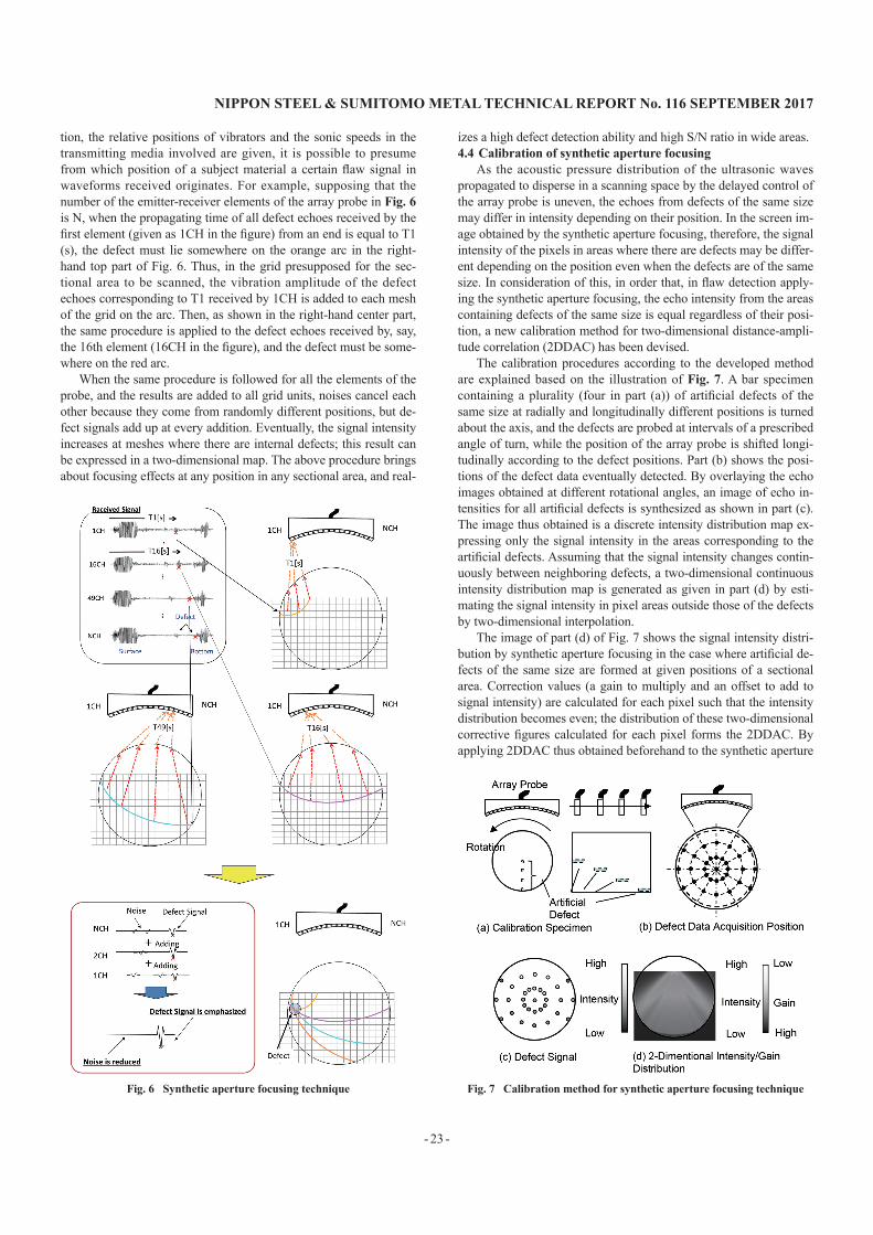
tion, the relative positions of vibrators and the sonic speeds in the transmitting media involved are given, it is possible to presume from which position of a subject material a certain flaw signal in waveforms received originates. For example, supposing that the number of the emitter-receiver elements of the array probe in Fig. 6 is N, when the propagating time of all defect echoes received by the first element (given as 1CH in the figure) from an end is equal to T1 (s), the defect must lie somewhere on the orange arc in the right-hand top part of Fig. 6. Thus, in the grid presupposed for the sec-tional area to be scanned, the vibration amplitude of the defect echoes corresponding to T1 received by 1CH is added to each mesh of the grid on the arc. Then, as shown in the right-hand center part, the same procedure is applied to the defect echoes received by, say, the 16th element (16CH in the figure), and the defect must be some-where on the red arc.
When the same procedure is followed for all the elements of the probe, and the results are added to all grid units, noises cancel each other because they come from randomly different positions, but de-fect signals add up at every addition. Eventually, the signal intensity increases at meshes where there are internal defects; this result can be expressed in a two-dimensional map. The above procedure brings about focusing effects at any position in any sectional area, and real-
izes a high defect detection ability and high S/N ratio in wide areas.4.4 Calibration of synthetic aperture focusing
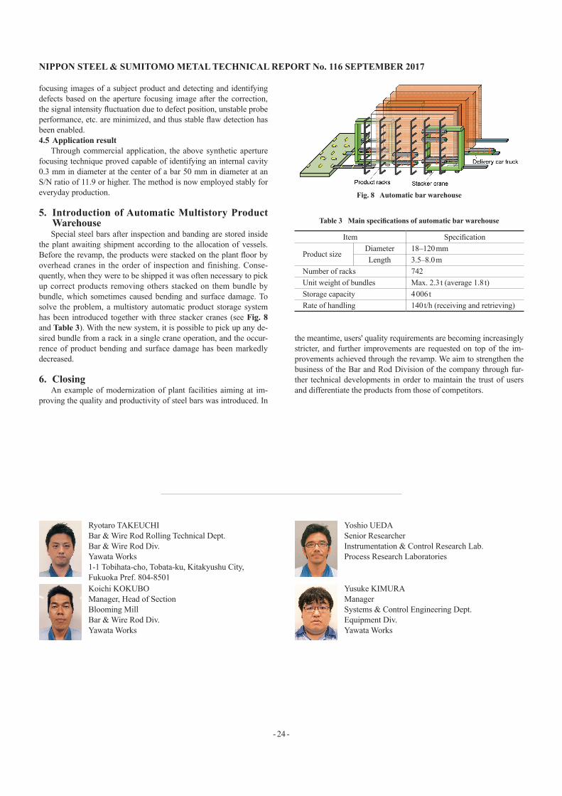
As the acoustic pressure distribution of the ultrasonic waves propagated to disperse in a scanning space by the delayed control of the array probe is uneven, the echoes from defects of the same size may differ in intensity depending on their position. In the screen im-age obtained by the synthetic aperture focusing, therefore, the signal intensity of the pixels in areas where there are defects may be differ-ent depending on the position even when the defects are of the same size. In consideration of this, in order that, in flaw detection apply-ing the synthetic aperture focusing, the echo intensity from the areas containing defects of the same size is equal regardless of their posi-tion, a new calibration method for two-dimensional distance-ampli-tude correlation (2DDAC) has been devised.
The calibration procedures according to the developed method are explained based on the illustration of Fig. 7. A bar specimen containing a plurality (four in part (a)) of artificial defects of the same size at radially and longitudinally different positions is turned about the axis, and the defects are probed at intervals of a prescribed angle of turn, while the position of the array probe is shifted longi-tudinally according to the defect positions. Part (b) shows the posi-tions of the defect data eventually detected. By overlaying the echo images obtained at different rotational angles, an image of echo in-tensities for all artificial defects is synthesized as shown in part (c). The image thus obtained is a discrete intensity distribution map ex-pressing only the signal intensity in the areas corresponding to the artificial defects. Assuming that the signal intensity changes contin-uously between neighboring defects, a two-dimensional continuous intensity distribution map is generated as given in part (d) by esti-mating the signal intensity in pixel areas outside those of the defects by two-dimensional interpolation.
The image of part (d) of Fig. 7 shows the signal intensity distri-bution by synthetic aperture focusing in the case where artificial de-fects of the same size are formed at given positions of a sectional area. Correction values (a gain to multiply and an offset to add to signal intensity) are calculated for each pixel such that the intensity distribution becomes even; the distribution of these two-dimensional corrective figures calculated for each pixel forms the 2DDAC. By applying 2DDAC thus obtained beforehand to the synthetic aperture
Fig. 6 Synthetic aperture focusing technique Fig. 7 Calibration method for synthetic aperture focusing technique
NIPPON STEEL & SUMITOMO METAL TECHNICAL REPORT No. 116 SEPTEMbER 2017
- 24 -
focusing images of a subject product and detecting and identifying defects based on the aperture focusing image after the correction, the signal intensity fluctuation due to defect position, unstable probe performance, etc. are minimized, and thus stable flaw detection has been enabled.4.5 Application result
Through commercial application, the above synthetic aperture focusing technique proved capable of identifying an internal cavity 0.3 mm in diameter at the center of a bar 50 mm in diameter at an S/N ratio of 11.9 or higher. The method is now employed stably for everyday production.
5. Introduction of Automatic Multistory Product WarehouseSpecial steel bars after inspection and banding are stored inside
the plant awaiting shipment according to the allocation of vessels. Before the revamp, the products were stacked on the plant floor by overhead cranes in the order of inspection and finishing. Conse-quently, when they were to be shipped it was often necessary to pick up correct products removing others stacked on them bundle by bundle, which sometimes caused bending and surface damage. To solve the problem, a multistory automatic product storage system has been introduced together with three stacker cranes (see Fig. 8 and Table 3). With the new system, it is possible to pick up any de-sired bundle from a rack in a single crane operation, and the occur-rence of product bending and surface damage has been markedly decreased.
6. ClosingAn example of modernization of plant facilities aiming at im-
proving the quality and productivity of steel bars was introduced. In
the meantime, users' quality requirements are becoming increasingly stricter, and further improvements are requested on top of the im-provements achieved through the revamp. We aim to strengthen the business of the Bar and Rod Division of the company through fur-ther technical developments in order to maintain the trust of users and differentiate the products from those of competitors.
Fig. 8 Automatic bar warehouse
Table 3 Main specifications of automatic bar warehouse
Item Specification
Product sizeDiameter 18–120 mmLength 3.5–8.0 m
Number of racks 742Unit weight of bundles Max. 2.3 t (average 1.8 t)Storage capacity 4 006 tRate of handling 140 t/h (receiving and retrieving)
Ryotaro TAKEUCHIBar & Wire Rod Rolling Technical Dept.Bar & Wire Rod Div.Yawata Works1-1 Tobihata-cho, Tobata-ku, Kitakyushu City, Fukuoka Pref. 804-8501
Yoshio UEDASenior ResearcherInstrumentation & Control Research Lab.Process Research Laboratories
Koichi KOKUBOManager, Head of SectionBlooming MillBar & Wire Rod Div.Yawata Works
Yusuke KIMURAManagerSystems & Control Engineering Dept.Equipment Div.Yawata Works


![[Steelworks] Edelstahlverarbeitung Edelstahl Messebau, Design, Kunst, Logos](https://img.pdfslide.net/doc/110x75/568c35131a28ab023592d800/steelworks-edelstahlverarbeitung-edelstahl-messebau-design-kunst-logos.jpg)