Embed Size (px)
Citation preview

NIPPON STEEL & SUMITOMO METAL TECHNICAL REPORT No. 113 DECEMBER 2016
- 49 -
1. IntroductionDue to the progress of redevelopment projects in waterfront ar-
eas in recent years, there is a tendency for residential areas and plants to be located adjacent to port facilities. For this reason, im-pact hammer driving of steel pipe piles using hammers in port facili-ties as conventionally employed has been increasingly difficult in the face of issues associated with noise and vibration. In addition, with continued increases in quay water depth and in the size of port facilities mainly in subject governmental strategy aimed at strength-ening the international competitiveness of port facilities, there is de-mand for the rationalization of structures from the viewpoint of eco-nomic efficiency. Therefore, the bearing capacity required per steel pipe pile is becoming larger, resulting in an increase in the size of piles.
Against this background, Nippon Steel & Sumitomo Metal Corpo-ration has developed the RS Plus™ method in collaboration with the Port and Airport Research Institute and Chowa Kogyo Co., Ltd. 1, 2) This is a steel pipe pile construction method in which soil cement block using soil cement is formed using a vibratory hammer togeth-er with a water jet (hereafter referred to as “WJ”) and cement milk jet (hereafter referred to as “CJ”). The use of a Vibro hammer makes it possible to construct a soil cement block that realizes high bearing capacity, while generating less vibration and noise than that generat-ed using the impact hammer driving method. The RS Plus™ method was first introduced in the market in 2009 with its applicable maxi-
mum pile diameter up to around 1 000 mm. The maximum pile di-ameter to which the method is applicable was further expanded by 2014 to 1 600 mm.
A key point in this construction method is the technology to con-struct robust soil cement block. Partly because there is a report stat-ing that it is difficult to gain bearing capacity by the vibratory pile driving as the ground is softened by this method when this method is applied in conjunction with WJ, 3) it is necessary to strengthen soil cement block in order to achieve high bearing capacity. For this rea-son, in the development, emphasis has been placed on clarifying a soil cement block formation phenomenon when using WJ and eval-uating the bearing capacity derived. This paper outlines the con-struction method and the development results that form the technical background, which is followed by the introduction of application examples.
2. Outline of the Construction Method2.1 Construction procedures
Figure 1 shows the processes in this method. First, a pile is put into a bearing layer up to a depth approximately three times the length of the pile diameter D using a Vibro hammer and a WJ to-gether (Fig. 1① –③ , and the ground in the vicinity of the pile tip is sufficiently excavated. After that, the WJ is switched to a CJ and the pile is vibrated using the Vibro hammer and is raised until the pile tip reaches the top surface of the bearing layer (Fig. 1④ –⑤ ),
Technical Report UDC 624 . 155
* Researcher, Steel Structures Research Lab., Steel Research Laboratories 20-1 Shintomi, Futtsu City, Chiba Pref. 293-8511
Development of New-type Steel-pile Method for Port FacilitiesShunsuke MORIYASU* Kazuo KUBOTAYoshiro ISHIHAMA Ryuta TANAKAMasakazu TAKENO Kenji NISHIUMIShinji TAENAKA Noriyoshi HARATA
AbstractA pile driving method with small noise and small ground vibration is needed in port area,
because the noise and ground vibration caused by the hammer are problematic for neigh-boring industrial plants and residential area. In addition, there is a tendency that the scale of port structures is bigger, the water depth of quays is deeper and the structure system is getting rationalized. Because of these situations, Nippon Steel & Sumitomo Metal Corpora-tion has developed on the vibratory pile driving with water and cement milk jetting. This “RS Plus™” method can reduce the ground vibration and noise, and has possibility to get large bearing capacity. This paper shows the construction process of this method, the evalu-ation of the bearing capacity in the range of maximum 1 600 mm diameter piles.

NIPPON STEEL & SUMITOMO METAL TECHNICAL REPORT No. 113 DECEMBER 2016
- 50 -
which is followed by sinking the pile down again to a depth of 2 D from the top surface of the bearing layer (Fig. 1⑥ ). With an up-and-down movement of the pile using CJ together in this way, the ground and cement milk are stirred and mixed, forming a soil ce-ment block. When skin friction is needed, cement milk is applied to the steel pipe surface while pulling out the jet pipe (Fig. 1⑦ ).
As shown in Fig. 2, construction facilities used for this construc-tion method consist of a water and cement milk jet cutter for the WJ and CJ, a mixing plant, and others in addition to a Vibro hammer and a crane required for pile driving. While Fig. 2 is a schematic view of construction facilities on the sea using a barge, work on the land along a quay is of course possible.
In order to produce homogeneous soil cement block, the amount of cement milk to be fed by controlling the flow rate of cement milk fed by pressure, the pressure used for the jetting, and the timing of switching from the WJ to CJ are specified in accordance with the di-ameter of the steel pipe pile used. Furthermore, the depth and rate of pile driving are controlled with a laser displacement meter attached to the Vibro hammer.2.2 Pile structure
The following two types of pile tip structures can be used ac-cording to the application conditions.(1) Outer rib plate type
As indicated in Fig. 3, in this system, rib plates are radially at-tached to the outer peripheral surface of a steel pipe, and nozzles of the WJ and CJ are placed on the pipe tip peripheral surface (hereaf-ter referred to as the “outer rib plate type”). This system is suitable for pipes with small and medium-sized diameters of 1 000 mm max-imum, and the length of the rib plates in the horizontal direction is set up such that the area of the soil cement block base becomes about two times closed pile area. Bearing capacity can be obtained
by forming a large soil cement block relative to the pile diameter.(2) Inner rib plate type
As shown in Fig. 4, this system has a rib plate attached on the inner surface of the pipe such that the plate partitions the inner space of the pipe, and also such that nozzles are placed on both the pipe peripheral surface and the rib plate (hereafter referred to as the “in-ner rib plate type”). Since this system allows for construction of a robust soil cement block even for a large-diameter pile with a pipe diameter exceeding 1 000 mm, the use of WJ and CJ using the noz-zles attached to rib plates makes it possible to excavate and stir the soil in the position of the pile center directly.
Both types are provided with multiple rows of slip keeper on the inner peripheral surface of the pipe tip to prevent the soil cement from moving, so as to secure the attachment of the pipe and soil ce-ment.
3. DevelopmentIn order to strengthen the soil cement block, it is necessary to
appropriately adjust the injection pressure and flow rate of the jets to the steel pipe diameter and soil conditions. For this purpose, we have to clarify the phenomenon whereby ground is excavated by
Fig. 1 Construction process
Fig. 2 Construction facilities
Fig. 3 Outer rib plate type
Fig. 4 Inner rib plate type

NIPPON STEEL & SUMITOMO METAL TECHNICAL REPORT No. 113 DECEMBER 2016
- 51 -
WJ. Therefore, we have decided to take the following steps: (1) un-derstanding such phenomenon through experiments using models, then (2) verifying the constructability of a soil cement block through tests using mock-ups on a full scale, followed by (3) clarifying the bearing capacity performance through the static load test. A detailed explanation of steps (1) to (3) is given as follows.(1) Clarification of excavated soil range excavate by a WJ
Two experiments are conducted using models 4): an experiment for basic soil excavating by a WJ with a single nozzle; and an ex-periment simulating the RS Plus™ method construction using mul-tiple nozzles and a steel pipe. To start, an experiment using a single nozzle is conducted. In this experiment, saturated sand ground is prepared inside a sand box that is set to a centrifugal loading equip-ment, and the nozzle is arranged along the side face acrylic resin wall of the sand box as shown in Fig. 5 (a). The overburden pres-sure applied is varied as Cases 1–4 as shown in Table 1 by changing the centrifugal acceleration (1–40 G) in order to observe the rela-tionship between the overburden pressure and the excavated range. An example of the experimental results is shown in Photo 1. The range of excavating by the WJ is the white range in the shape of a teardrop under the nozzle hole. It is reported 5) that when large ener-gy is applied to sandy soil by a WJ, an increase in the excess pore water pressure will cause the effective stress to decrease, which weakens the bond between soil particles, thus facilitating excavat-ing. Moreover, based on this principle, jet penetration distance R can be derived using injection pressure P and the flow rate (nozzle di-ameter d0 ), and the soil resistance (such as total stress σz and angle of shearing resist-ance φ’ ) and fluid loss coefficient Λ.
Figure 6 in which Cases 1–4 are plotted shows the experimental results summarized using dimensionless quantities consisting of re-spective parameters, using the above-mentioned finding in a past re-
port as a reference. Cases 1–4 are plotted on a straight line, and the applicability of the finding in the past report is high within the scope of this experiment. While the finding in the past report 5) was veri-fied by field experiments up to 8 m in depth (overburden pressure: approx. 150 kPa), this experiment has verified in a centrifugal field that the finding is also applicable to cases with a larger overburden pressure of 213 kPa. Additionally, in all of the cases, the maximum excavation width shown in Photo 1 becomes approximately 0.6 times the excavated distance. Moreover, also in all of the cases, the excavated range takes the shape of a teardrop. Accordingly, know-ing jet penetration distance R allows the excavated range to be ob-tained.
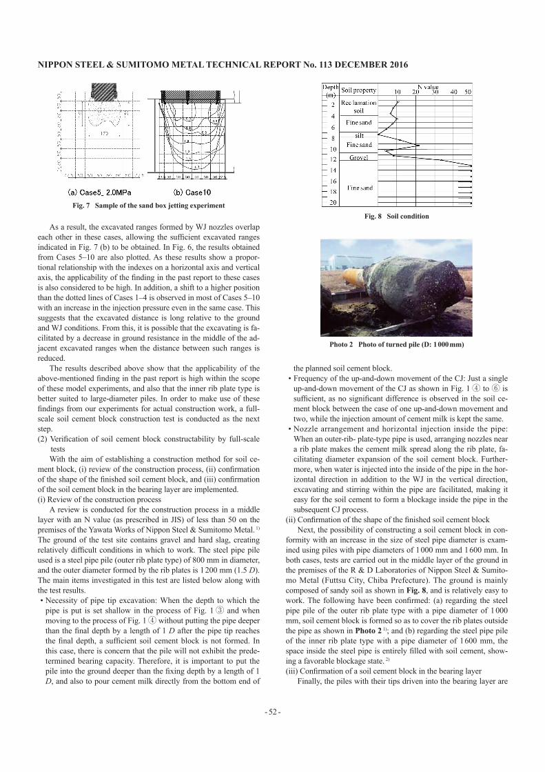
Next, by an experiment simulating construction employing the RS Plus™ method, an examination is conducted as to whether the excavated range that is sufficient to form a soil cement block area can be obtained using a WJ inside a sand box with saturated sand ground under 1G. As shown in Fig. 5 (b), nozzles are attached to both ends of the steel pipe tip of the test piles for Cases 5–8 in Table 1, simulating the outer rib plate type. As shown in Fig. 7 (a), in Cas-es 5–7 using piles with relatively smaller diameters, the excavated ranges formed by the WJ from both ends of the steel pipe pile over-lap each other, thus resulting in excavating the entire part of the ground just below the steel pipe pile.
However, a sufficient excavated range is not obtained in Case 8 with a large-diameter pile in which the area of the ground to be ex-cavate is larger. Therefore, in Case 9, simulating the inner rib plate type, a triple-nozzle WJ is formed with nozzles arranged on the pile center line in addition to both ends of the steel pipe as shown in Fig. 5 (c). Furthermore, in Case 10, each WJ nozzle located at both ends of the pipe is inclined and oriented inward so that the injection di-rections of both nozzles focus on the center.
Table 1 Cases of water jetting experiment
Pile diameter
(mm)
Nozzle diameter
(mm)
Injection pressure(MPa)
Soil total stress(kPa)
Centrifuge(1–40 G)
Case1 - 1.0 0.69 1.2Case2 - 2.0 0.45 45.9Case3 - 2.0 0.56 103.1Case4 - 2.0 0.85 213.4
Sand box(1 G)
Case5 101.6 1.0 1.0–2.5 10.1Case6 101.6 1.3 1.0–3.0 10.1Case7 216.3 1.0 1.5–3.0 10.1Case8 318.5 2.0 0.3–1.5 10.1Case9 318.5 2.0 0.3–2.0 10.1Case10 318.5 2.5 0.3–1.8 10.1
Fig. 5 WJ position of the experiment Photo 1 Sample of the centrifuge jetting experiment
Fig. 6 Relationship amoung the WJ specification, soil resistance and jet penetration distance
NIPPON STEEL & SUMITOMO METAL TECHNICAL REPORT No. 113 DECEMBER 2016
- 52 -
As a result, the excavated ranges formed by WJ nozzles overlap each other in these cases, allowing the sufficient excavated ranges indicated in Fig. 7 (b) to be obtained. In Fig. 6, the results obtained from Cases 5–10 are also plotted. As these results show a propor-tional relationship with the indexes on a horizontal axis and vertical axis, the applicability of the finding in the past report to these cases is also considered to be high. In addition, a shift to a higher position than the dotted lines of Cases 1–4 is observed in most of Cases 5–10 with an increase in the injection pressure even in the same case. This suggests that the excavated distance is long relative to the ground and WJ conditions. From this, it is possible that the excavating is fa-cilitated by a decrease in ground resistance in the middle of the ad-jacent excavated ranges when the distance between such ranges is reduced.
The results described above show that the applicability of the above-mentioned finding in the past report is high within the scope of these model experiments, and also that the inner rib plate type is better suited to large-diameter piles. In order to make use of these findings from our experiments for actual construction work, a full-scale soil cement block construction test is conducted as the next step.(2) Verification of soil cement block constructability by full-scale
testsWith the aim of establishing a construction method for soil ce-
ment block, (i) review of the construction process, (ii) confirmation of the shape of the finished soil cement block, and (iii) confirmation of the soil cement block in the bearing layer are implemented.(i) Review of the construction process
A review is conducted for the construction process in a middle layer with an N value (as prescribed in JIS) of less than 50 on the premises of the Yawata Works of Nippon Steel & Sumitomo Metal. 1)
The ground of the test site contains gravel and hard slag, creating relatively difficult conditions in which to work. The steel pipe pile used is a steel pipe pile (outer rib plate type) of 800 mm in diameter, and the outer diameter formed by the rib plates is 1 200 mm (1.5 D). The main items investigated in this test are listed below along with the test results.• Necessity of pipe tip excavation: When the depth to which the
pipe is put is set shallow in the process of Fig. 1③ and when moving to the process of Fig. 1④ without putting the pipe deeper than the final depth by a length of 1 D after the pipe tip reaches the final depth, a sufficient soil cement block is not formed. In this case, there is concern that the pile will not exhibit the prede-termined bearing capacity. Therefore, it is important to put the pile into the ground deeper than the fixing depth by a length of 1 D, and also to pour cement milk directly from the bottom end of
the planned soil cement block.• Frequency of the up-and-down movement of the CJ: Just a single
up-and-down movement of the CJ as shown in Fig. 1④ to ⑥ is sufficient, as no significant difference is observed in the soil ce-ment block between the case of one up-and-down movement and two, while the injection amount of cement milk is kept the same.
• Nozzle arrangement and horizontal injection inside the pipe: When an outer-rib- plate-type pipe is used, arranging nozzles near a rib plate makes the cement milk spread along the rib plate, fa-cilitating diameter expansion of the soil cement block. Further-more, when water is injected into the inside of the pipe in the hor-izontal direction in addition to the WJ in the vertical direction, excavating and stirring within the pipe are facilitated, making it easy for the soil cement to form a blockage inside the pipe in the subsequent CJ process.
(ii) Confirmation of the shape of the finished soil cement blockNext, the possibility of constructing a soil cement block in con-
formity with an increase in the size of steel pipe diameter is exam-ined using piles with pipe diameters of 1 000 mm and 1 600 mm. In both cases, tests are carried out in the middle layer of the ground in the premises of the R & D Laboratories of Nippon Steel & Sumito-mo Metal (Futtsu City, Chiba Prefecture). The ground is mainly composed of sandy soil as shown in Fig. 8, and is relatively easy to work. The following have been confirmed: (a) regarding the steel pipe pile of the outer rib plate type with a pipe diameter of 1 000 mm, soil cement block is formed so as to cover the rib plates outside the pipe as shown in Photo 2 1); and (b) regarding the steel pipe pile of the inner rib plate type with a pipe diameter of 1 600 mm, the space inside the steel pipe is entirely filled with soil cement, show-ing a favorable blockage state. 2)
(iii) Confirmation of a soil cement block in the bearing layerFinally, the piles with their tips driven into the bearing layer are
Fig. 7 Sample of the sand box jetting experimentFig. 8 Soil condition
Photo 2 Photo of turned pile (D: 1 000 mm)

NIPPON STEEL & SUMITOMO METAL TECHNICAL REPORT No. 113 DECEMBER 2016
- 53 -
confirmed. Instead of digging up these piles, the soil cement block length, the homogeneity of the soil cement, etc., are examined through boring investigation of the inside of the steel pipes. 4) As an example, the results of a steel pipe pile with a pipe diameter of 1 300 mm are described. The test site is in the premises of the R & D Lab-oratories as described above. The pile is the inner rib plate type, and its nozzle arrangement and hole diameters are set as shown in Fig. 9. The hatched areas in the same figure indicate the supposed excava-tion area by the WJ considered in view of the findings obtained as described in the previous section. Through the boring investigation inside the steel pipe after the driving work, core samples as shown in Photo 3 are obtained from a depth deeper than the pipe tip by a length of 1.5 D, indicating that the soil cement block length satisfies the predetermined value of 1.0 D. Moreover, as shown in Photo 4, it is confirmed using an X-ray-CT device that the core cross sections have little variation in density and that homogeneity is high as a whole.
From the above-described findings, it is confirmed that soil ce-ment block can be formed using this method at full scale. It is also confirmed that further application of the findings and a construction procedure derived from the model experiments described in the pre-vious sections are feasible.(3) Evaluation of the bearing capacity performance
Regarding the bearing capacity performance, a design formula is proposed after evaluating it based on a static loading test. 6) The test cases are shown in Table 2. The test sites are in two locations: one
in the premises of the R & D Laboratories as mentioned above, and the other in the vicinity of the R & D Laboratories. The characteris-tics of the bearing layer of the two sites (at least 12.3 m deep as shown in Fig. 8) are considered to be the same, and this test is deemed to be a comparison made for the same ground. In addition to the RS Plus™ method (Cases A–C), a pile driven by the impact hammer driving method 7) (Case D) is also included in the test for making a comparison.(i) Pile end resistance force
The relationship between pile end load and pile tip displacement is shown in Fig. 10. In this test, the tip resistance force in Cases A–C is defined as the axial force calculated using a strain gauge at-tached in the position above the pipe tip by a length of 2 D (soil ce-ment block top end), while the tip resistance force in Case D is de-fined as the axial force in the position above the pipe tip by a length of 5 D (bearing layer top end). As can be seen from Fig. 10, there is a gradual increase in the tip resistance force as the pile diameter in-creases in Cases A–C, and a comparison between Case B and Case D with the same diameter indicates that the tip resistance force of a pile driven using the RS Plus™ method is clearly greater than that of a pile driven using the conventional impact hammer driving method.
Next, whether the failure mode in limit resistance is caused by the fracture of the ground or the fracture of the soil cement block is
Fig. 9 Position of jetting nozzle and supposed excavation area
Fig. 10 Pile end load and pile end displacement
Table 2 Test condition and main result of the static load test
Case Case A Case B Case C Case DD (mm) 600 800 1 300 800
Driving method RS plus™ RS plus™ RS plus™Impact hammer
Pile type Outer rib Outer rib Inner rib -
Pile edge depthG.L.
−18.0 mG.L.
−18.0 mG.L.
−16.0 mG.L.
−15.2 m
Pile end
Second limit resistance (kN)
6 199 8 767 10 992 3 700
Coefficient of resistance
438 349 166 147
Design value of coefficient of
resistance300 300 150 -
Photo 3 Soil-cement core bored from pile
Photo 4 X-ray-CT result of the core

NIPPON STEEL & SUMITOMO METAL TECHNICAL REPORT No. 113 DECEMBER 2016
- 54 -
estimated. Here, limit resistance is defined as the pile tip load (sec-ondary limit load) when the pile tip displacement reaches 0.1 D. 8) Table 2 shows the secondary limit load in each case. A value of 8.2 MPa is derived when the secondary limit load, 10 992 kN, in Case C without a diameter expansion effect as an inner rib plate type is em-ployed is divided by the steel pipe blockage area. This is lower than the uniaxial compressive strength of 13.2–30.7 MPa of soil cement test pieces sampled from the soil cement block. For this reason, it is considered that the soil cement block is not destroyed. In addition, based on structural tests for pile tip portions, 1) bearing strength Ri of slip keeper to prevent the soil cement from moving is designed us-ing formula (1).
Ri = ( D − 2 × t − di ) × π × di × σp × a × n × di (1)when the numerical values of this experiment (D: steel pipe diame-ter (=1 300 mm), t: plate thickness (= 25 mm), di: steel bar diameter (= 13 mm), σp: unconfined compression strength of soil cement (= 13.2 MPa), a: coefficient of bearing pressure (= 4), and n: number of rows of slip keeper to prevent the soil cement from moving (= 7)), are substituted in formula (1) above, bearing strength Ri of the slip keeper to prevent the soil cement from moving is 18 672 kN, which is significantly higher than the secondary limit load of 10 992 kN. This also suggests that no destruction has occurred in the soil ce-ment block. Instead, the secondary limit load is likely to be deter-mined by destruction of the ground, meaning that it is possible that larger bearing capacity can be obtained in harder ground.(ii) Skin friction
The skin friction intensity is obtained from the skin friction in each layer section with an N value of less than 50 divided by the pe-ripheral surface area. The result shows a tendency that the skin fric-tion intensity in sandy soil is proportional to the N value as shown in Fig. 11. For comparison purposes, the design lines as stipulated for cast-in-place piles (sand and gravel soil: 5 N, N ≤ 40) in the Specifications for Highway Bridges 9) are also shown in this figure, and it is evident that the skin friction intensity in each case is higher than these lines.
In addition, while only two data on skin friction intensity for co-hesive soil, 41.3 kN/m2 in Case B (82.6 N converted using the N value) and 170.7 kN/m2 (50.2 N converted using the N value) ob-tained from a test 1) separately conducted, have been obtained so far, these values are significantly higher than the design value of 10 N for cast-in-place piles that is stipulated in the Specifications for Highway Bridges.(iii) Design formula
In light of the above-described test results, formula (2) has been proposed as an equation that covers both outer-rib-plate- and inner-rib-plate-type pile tips, 2)
R = 300 αNβAp + Σ ( rfki Asi ) (2)here, R: bearing capacity of the pile (kN), N: N value (≤ 50) of the pile tip ground, Ap: steel pipe tip blockage cross section, rfki: pile skin friction intensity of layer i (kN/m2) (sandy soil: 5 N [upper lim-it: 200 kN/m2], cohesive soil: c or 10 N [upper limit: 150 kN/m2]), and Asi: peripheral area of the steel pipe in contact with the ground in layer i (m2). In addition, α is a coefficient that indicates variation in the resistance force in the same ground according to the construc-tion method used, and is set to 0.5 in the case of the RS Plus™ method when this is specified as 1.0 in the case of the impact ham-mer driving method. This means a reduction in the ground strength in the case of the RS Plus™ method as it is difficult to take into ac-count the displacement pile effect in this method unlike the impact hammer driving method, which is capable of excavated soil associ-ated with plugged pile. β is also a correction coefficient for taking into account the pile tip shape; β = 2.0 for the outer rib plate type where the diameter expansion of the soil cement block bottom area to two times the steel pipe blockage area is taken into account, and β = 1.0 for the inner rib plate type for which no diameter expansion can be taken into consideration.
For the bearing capacity coefficient of the pipe tip resistance force, a comparison between the test result values and the design formulae is shown in Table 2. The bearing capacity coefficients (test result values) indicated in the second row from the bottom of Table 2 are derived by dividing the secondary limit load by the steel pipe blockage area and an N value of 50, while the design values indicat-ed in the bottom row of Table 2 are derived from 300 αβ in formula (2). This indicates that design values that are smaller than the test result values are on the safe side, and it is also clear that the design values are applicable to both the outer rib plate and the inner rib plate types. A notable point in the comparison with the impact ham-mer driving method is that the bearing capacity coefficients in Case C and Case D are equivalent. In the case of the impact hammer driv-ing method, the larger the pile diameter becomes, the more difficult it is for blockage inside the pipes to occur, and thus it becomes harder to gain the necessary pipe tip resistance force. 8) Accordingly, if a pile of 1 300 mm in diameter is driven using the impact hammer driving method in this ground, it is highly likely that the bearing ca-pacity coefficient obtained becomes smaller than 166 in Case C. In addition to this, the design values of the skin friction in the RS Plus™ method as described above are equal to or larger than the de-sign values of the impact hammer driving method 8, 9) (sandy soil: 2 N [upper limit: 100 kN/m2], cohesive soil: c or 10 N [upper limit: 150 kN/m2]). From the findings described above, it is shown that the bearing capacity performance of the piles driven using the RS Plus™ method exceeds that when using the impact hammer driving method.
4. Application Examples4.1 Higashi port District quay (−9 m), Port of Karatsu
As part of intermodal transport terminal improvement projects promoted in order to improve the efficiency in transportation of in-creasing domestic general cargoes, and also in order to cope with the demand for large-sized passenger ships and for demand to se-cure transport functions in the case of a disaster, the existing old and outdated quay (constructed 40 years ago) in the port of Karatsu Higashi port District has been renovated as a quay with reinforce-ment against earthquakes.
Steel pipe piles of the quay are required to possess large resist-ance against push load, and they faced difficulties with the impact Fig. 11 Relationship between SPT-N and skin friction on sand
NIPPON STEEL & SUMITOMO METAL TECHNICAL REPORT No. 113 DECEMBER 2016
- 55 -
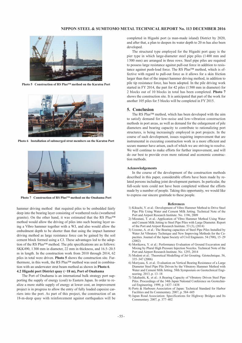
hammer driving method that required piles to be embedded fairly deep into the bearing layer consisting of weathered rocks (weathered granite). On the other hand, it was estimated that the RS Plus™ method would allow the driving of piles into such bearing layer us-ing a Vibro hammer together with a WJ, and also would allow the embedment depth to be shorter than that using the impact hammer driving method as large resistance force can be gained by the soil cement block formed using a CJ. These advantages led to the adop-tion of the RS Plus™ method. The pile specifications are as follows: SKK490, 1 300 mm in diameter, 22 mm in thickness, and 16.5–20.5 m in length. In the construction work from 2010 through 2014, 62 piles in total were driven. Photo 5 shows the construction site. Fur-thermore, in this work, the RS Plus™ method was used in combina-tion with an underwater strut beam method as shown in Photo 6.4.2 Higashi port District quay (−18 m), Port of Onahama
The Port of Onahama is an international bulk strategy port sup-porting the supply of energy (coal) to Eastern Japan. In order to re-alize a more stable supply of energy at lower cost, an improvement project is in progress to allow the entry of fully loaded capesize car-riers into the port. As part of this project, the construction of an 18-m-deep quay with reinforcement against earthquakes will be
completed in Higashi port (a man-made island) District by 2020, and after that, a plan to deepen its water depth to 20 m has also been developed.
The structural type employed for the Higashi port quay is the pier type in which large-diameter steel pipe piles (1 400 mm and 1 500 mm) are arranged in three rows. Steel pipe piles are required to possess large resistance against pull-out force in addition to resis-tance against push-load force. The RS Plus™ method, which is ef-fective with regard to pull-out force as it allows for a skin friction larger than that of the impact hammer driving method, in addition to pile tip resistance force, has been adopted. In the pile driving work started in FY 2014, the part for 42 piles (1 500 mm in diameter) for 2 blocks out of 10 blocks in total has been completed. Photo 7 shows the construction site. It is anticipated that part of the work for another 105 piles for 5 blocks will be completed in FY 2015.
5. ConclusionThe RS Plus™ method, which has been developed with the aim
to satisfy demand for low-noise and low-vibration construction methods in port areas, as well as demand for the enlargement of pile diameters and bearing capacity to contribute to rationalizing port structures, is being increasingly employed in port projects. In the course of such development, issues requiring improvement that are instrumental in executing construction work in a more efficient and secure manner have arisen, each of which we are striving to resolve. We will continue to make efforts for further improvement, and will do our best to provide even more rational and economic construc-tion methods.
AcknowledgementsIn the course of the development of the construction methods
described in this paper, considerable efforts have been made by re-lated persons including joint development partners. In particular, the full-scale tests could not have been completed without the efforts made by a number of people. Taking this opportunity, we would like to express our sincere gratitude to these people.
References1) Kikuchi, Y. et al.: Development of Vibro Hammer Method to Drive Steel
Pipe Pile Using Water and Cement Milk Jetting. Technical Note of the Port and Airport Research Institute. No. 1196, 2009
2) Mizutani, T. et al.: Application of Vibro Hammer Method Using Water and Cement Milk Jetting to Steel Pipe Piles with Large Diameter. Report of the Port and Airport Research Institute. 53 (3), (2014)
3) Uezono, A. et al.: The Bearing capacities of Steel Pipe Piles Installed by Water Jet Vibratory Technique and New Improving Methods for the Ca-pacities. Journal of the Japan Society of Civil Engineers. 54 (700), 15–29 (2002)
4) Morikawa, Y. et al.: Performance Evaluation of Ground Excavation and Mixing by Plural High Pressure Injection Nozzles. Technical Note of the Port and Airport Research Institute. No. 1293, 2014
5) Modoni et al.: Theoretical Modelling of Jet Grouting. Géotechnique. 56, 335–347 (2006)
6) Moriyasu, S. et al.: Evaluation on Vertical Bearing Resistance of a Large Diameter Steel Pipe Pile Driven by the Vibratory Hammer Method with Water and Cement Milk Jetting. 58th Symposium on Geotechnical Engi-neering. 2013, p. 13–18
7) Takahashi, K. et al.: A Bearing Capacity of Vibratory Driven Steel Pipe Piles. Proceedings of the 34th Japan National Conference on Geotechni-cal Engineering. 1999, p. 1437–1438
8) Ports & Harbours Association of Japan: Technical Standard for Harbor Facilities and Its Commentary. 2007, p. 584–605
9) Japan Road Association: Specifications for Highway Bridges and Its Commentary. 2007, p. 377–402
Photo 5 Construction of RS Plus™ method on the Karatsu Port
Photo 6 Installation of submerged strut members on the Karatsu Port
Photo 7 Construction of RS Plus™ method on the Onahama Port

NIPPON STEEL & SUMITOMO METAL TECHNICAL REPORT No. 113 DECEMBER 2016
- 56 -
Shunsuke MORIYASUResearcherSteel Structures Research Lab.Steel Research Laboratories20-1 Shintomi, Futtsu City, Chiba Pref. 293-8511
Masakazu TAKENOManagerFoundation Products Engineering Dept.-IIConstruction Products Development Div.Construction Products Unit
Kazuo KUBOTASenior ManagerFoundation Products Engineering Dept.-IIConstruction Products Development Div.Construction Products Unit
Kenji NISHIUMIGeneral Manager, Head of Div.Osaka Office
Yoshiro ISHIHAMASenior ResearcherSteel Structures Research Lab.Steel Research Laboratories
Shinji TAENAKASenior Researcher, Ph.D.Steel Structures Research Lab.Steel Research Laboratories
Ryuta TANAKAManagerFoundation Products Engineering Dept.-IIConstruction Products Development Div.Construction Products Unit
Noriyoshi HARATASenior Manager, Head of Dept.Foundation Products Engineering Dept.-IIConstruction Products Development Div.Construction Products Unit