Embed Size (px)
Citation preview

“TECHNICAL REQUIREMENTS FOR PARALLEL
OPERATION OF MEMBER-OWNED
GENERATION”
EFFECTIVE JANUARY 27, 2014

1
TECHNICAL CONSIDERATIONS COVERING PARALLEL OPERATIONS OF CUSTOMER OWNED GENERATION
INTERCONNECTED WITH THE DELAWARE ELECTRIC CO-OP
Table of Contents
Topics Page No.
Disclaimer ................................................................................................................................. 18
Prerequisites & Interconnection Process ................................................................................... 18
Applicability ............................................................................................................................. 18
Definitions ................................................................................................................................ 20
Introduction and Purpose .......................................................................................................... 23
Generator Owner Obligations ................................................................................................... 24
DEC Power Delivery Obligations ............................................................................................. 27
Technical Design Considerations ............................................................................................. 28
Performance Considerations ..................................................................................................... 40
Protection Scheme Details ........................................................................................................ 44
Typical One-Line Diagrams ..................................................................................................... 48
Interconnection Application for Non-PJM Generation ............................................................. 60
References ................................................................................................................................ 61
Appendices Appendix A – Generator Protection Guidelines for Units 50 MW & Above
Appendix B – Information to Be Supplied By Generator Owner for Non PJM Projects
Appendix C – Delaware Electric Co-op Generator Interconnection Applications (25 kW or Less)
Appendix D – Delaware Electric Co-op Generator Interconnection Applications (Greater than 25kW) Appendix E – Typical Basic One Line Diagrams

2
TECHNICAL CONSIDERATIONS COVERING PARALLEL OPERATIONS OF CUSTOMER OWNED GENERATION
INTERCONNECTED WITH THE DELAWARE ELECTRIC CO-OP
I. Disclaimer This document and all the material contained herein is designed for informational and illustrative purposes and to insure at least minimum interconnection requirements are satisfied. It is produced as an aid to those Customers contemplating the purchase of generation equipment and interconnecting this generation equipment with the Delaware Electric Co-op. The information is intended to guide the customer in making a decision on whether to proceed with a more detailed engineering study. All the information in this document is intended to be typical and of a general nature for information purposes. It is not intended to be site or facility specific. Requirements and practices are also subject to change and it must be recognized that any given item may become obsolete or be modified in the future. The requirements in this document are the requirements of Delaware Electric Co-op (DEC), and may also be requirements of the PJM Interconnection. For generation interconnections in the PJM queue, the PJM Tariff shall prevail in the event of any contradiction between the requirements of this document and the PJM Tariff.
II. Prerequisite & Interconnection Process To interconnect with the Delaware Electric Co-op (DEC) System, the Customer must first be in compliance with the tariff rules and regulations and the applicable tariff classifications and rates. The terms and conditions contained within this document are in addition to, but do not modify nor negate, the terms of the tariff. In cases where the Customer will not be selling energy and/or capacity into PJM markets, a Generator Owner can submit an Interconnection Application and enter into an Interconnection Agreement Contract directly with Delaware Electric Co-op (DEC). This two-party Interconnection Agreement Contract will cover the interconnection and the use of DEC’s facilities to enable the transfer of power from or to the Facility. The details of the Interconnection Agreement Contract are outside the scope of this document. However, this Technical Considerations Document may be included in and become part of the overall Interconnection Agreement Contract. Alternatively, if the Customer intends to sell energy and or capacity into PJM markets, a Generator Owner must submit an Interconnection Request directly to PJM. PJM will initiate a process to study the feasibility of the generation, its impact within the PJM transmission system and the cost to make any necessary transmission system improvements. These transmission system improvements may be outside the service territory of the local utility. The extent of the studies is dependent on the size of the generation and the proposed Point of Interconnection. Again, the details of this process are outside the scope of this document. The Generator Owner must also enter into the appropriate agreement with PJM.
III. Applicability Unless otherwise provided, these technical considerations apply to all Customer owned generation interconnected with and operating in parallel with the DEC System at voltages up to and including 138 kV. Where multiple generators are connected to the Grid through a single Point of Common Coupling, the sum of the generator ratings will be used to determine the applicability of these Technical Considerations. These technical considerations also apply to NEM (Net Energy Metering) generator interconnections.

3
Control, Protection and Safety Equipment Requirements Specific to Generators of 25 kW or less.
All Generator Owner generators 25 kW or less may be single phase if electric service is single phase. Customer owned generators greater than 25 kW must be evaluated by the Company to determine if it can be single phase. For a three phase service, single phase generation will be considered by the Company if it is limited to 50 percent of the customers load on the phase in which it is installed. The following table describes necessary control, protection and safety equipment specific to generators of 25 kW or less connected to Secondary or Primary Voltage Systems:
Control, Protection and Safety Equipment for Generators 25 kW1
or Less Connected to Secondary or Primary System Generator Size 25 kW or Less Generator Disconnect Device X Over-Current Trip X Over-Voltage Trip X Under-Voltage Trip X Over/Under Frequency Trip X Synchronizing Check2 Manual or Automatic Notes: 1. Exporting to the DEC system may require additional operational/protection devices. 2. For synchronous and other type of generators with stand-alone capability
Disconnection and Reconnection. The Company may disconnect a distributed generation unit under the following conditions:
1) Application Termination - Upon termination of the approved Interconnection Application.
2) Non Compliance - For non-compliance with the technical guidelines specified in this document or other requirements contained in the applicable Customer Tariff, provided that the Company has given notice to the Generator Owner and provided the Generator Owner reasonable time (consistent with the condition) to correct such non-compliance. The Company will reconnect the unit only upon receipt of certification from the Generator Owner and verification by the Company that the unit is in compliance. The Company will provide verification within a reasonable time period.
3) In case of a system emergency or outage of the Company’s primary Electrical Source - The Generator Owner’s generation equipment must be installed and configured so that parallel operation must cease immediately and automatically during outages or loss of the Company’s electric source in accordance with these guidelines. The Generator Owner must also cease parallel operation upon notification by the Company of a system emergency, abnormal condition or in cases where such operation is determined to be unsafe, interferes with the supply of service to other customers or interferes with the Company’s system maintenance or operation. In addition, the Company may disconnect the generator from the system for system emergencies without notice. However, the Company will use reasonable efforts to notify the Generator Owner prior to disconnecting.
4) For Routine Maintenance and Repairs - The Company may disconnect a Customer/Generator Owner for routine maintenance and repairs on the Company’s system consistent with applicable tariffs and agreements. The Company will make reasonable efforts to provide advance notice to the Customer/Generator Owner of service interruptions resulting from routine maintenance. The Company will reconnect the Customer/Generator Owner as quickly as possible following any such service interruption.
5) Disconnect Means – The Customer/Generator Owner shall have a disconnect switch within 3 feet of the meter.

4
IV. Termination
The Generator Owner may terminate the approved Interconnection Application at any time upon thirty (30) days of providing written notice to the Company. The Company may terminate the Interconnection Application for cause after 60 days written notice to the Generator Owner of a material violation of the terms of the approved Interconnection Application and after the Generator Owner has had a reasonable opportunity to remedy the violation. The Generator Owner must give the Company notice that it intends to permanently shut down his generation.
V. Definitions Various terms as utilized in this document are defined below. Whenever used in the document with initial capitalization, the following terms have the meanings specified in this Section.
A. Account – An account is one metered or un-metered rate or service classification which normally has one electric delivery point of service. Each account shall have only one electric service supplier providing full electric supply requirements for that account. A premise may have more than one account.
B. Company – Delaware Electric Cooperative (DEC).
C. Customer – Any adult person, partnership, association, corporation, or other entity: (i) in whose name
a service account is listed, (ii) who occupies or is the ratepayer for a premises, building, structure, etc., and (iii) who is primarily responsible for payment of bills. A Customer includes anyone taking Delivery Service or combined Electric Supply & Delivery Service from the Company under one service classification for one account, premises or site. Multiple premises or sites under the same name are considered multiple Customers.
D. Facility (or Facilities) – The Customer owned generating equipment and all associated or ancillary
equipment, including Interconnection Equipment, on the Customer’s side of the Point of Common Coupling (Point of Interconnection).
E. Generator Owner – The owner of the generation Facility that is interconnected to the Company.
F. Grid – The interconnected arrangement of lines, transformers and generators that make up the electric
power system.
G. Interconnection – The physical connection of Customer owned generation to the DEC System in accordance with these technical considerations so that parallel operation can safely occur.
H. Interconnection Application – The standard form of application which must be submitted by the
Generation Owner to the Company as a request to interconnect a generating unit to the Delaware Electric Cooperative (DEC) System or to increase the capacity of a generating unit already connected to the DEC System.
I. Interconnection Equipment – That equipment necessary to safely interconnect the Facility to the DEC
System, including any and all relaying, interrupting devices, metering or communication equipment needed to protect the Facility and the DEC system and to control and safely operate the Facility in parallel with the DEC System.
J. Interface (Isolation) Transformer – A transformer which interconnects a privately owned generation
source voltage with the DEC System voltage. K. Inverter – A static power converter with control, protection and filtering functions that converts Direct
Current (DC) input to Alternating Current (AC) output. Inverters connected to the DEC System must be of the non-islanding type.

5
L. Island – A portion of the DEC System containing both load and generation that is electrically isolated from the remainder of the DEC System.
M. NEM - Net Energy Metering – Generation installed to offset a Customer’s energy usage and may
occasionally export power to the Grid. Maximum generation size and acceptable fuel source are dictated by the various State jurisdictions.
N. NERC - North American Electric Reliability Council. – The purpose of NERC is to ensure the
adequacy, reliability and security of the bulk electric supply systems through coordinated operations and planning of generation and transmission facilities.
O. One Way Power Flow – An interconnected Facility is classified as a “One Way Power Flow”
installation if the Facility is configured such that its load is always greater than the generation capacity or the Facility does NOT propose to export excess generated power through the DEC Power Delivery transmission and distribution system. This type of installation will receive power through the DEC interconnection but will never export power back into the DEC Power Delivery transmission and distribution system.
P. Parallel Operation – Any electrical connection between the DEC System and the Generator Owner’s
generation source. Q. DEC System – The electric system of DEC, in whose geographical service area the Customer’s
Facility is electrically connected, including transmission and distribution systems.
R. PJM - PJM Interconnection, L.L.C. – PJM Interconnection is a regional transmission organization (RTO) that coordinates the movement of wholesale electricity in all or parts of 13 States and the District of Columbia. Members include electric utilities and independently owned generating resources. The organization is responsible for dispatching generation, operating the bulk transmission system within its service area and operating a buy/sell market for member’s generation.
S. Point of Common Coupling (or PCC) – The point where the electrical conductors of the DEC System
are connected to the Generator Owner’s conductors and where any transfer of electric power between the Generator Owner and the Company takes place. The term Point of Interconnection (POI) used by PJM and other entities is synonymous to Point of Common Coupling.
T. Point of Interconnection (POI) – See definition for “Point of Common Coupling” above.
U. Pre-Interconnection Study – A technical study or studies which may be undertaken by either the
Company and/or PJM in response to its receipt of a completed Interconnection Application for Parallel Operation with the DEC System submitted on the Interconnection Application form prescribed by these technical considerations or by PJM. Pre-Interconnection Studies may include, but are not limited to, service studies, coordination studies and facilities impact studies.
V. RFC – ReliabilityFirst Corporation – One of eight Regional Reliability Councils which together form
the North American Electric Reliability Council (NERC). RFC is responsible for thirteen States and the District of Columbia including all the DEC service territories in Delaware.
W. RTU (Remote Terminal Unit) – The remote unit of a supervisory control system used to telemeter
operating data, provide device status/alarms and to provide remote control of equipment at a substation or generator site. The unit communicates with a master unit at the DEC Control Center.
X. Stabilized – The state of the Company’s system when the voltage and frequency have returned to their
normal range for at least 5 minutes or longer following a disturbance after which tripped Customer owned generation may reconnect to the DEC System. The Company may require a longer time period upon a reasonable showing that reconnection after only 5 minutes will adversely impact the safety and reliability of the DEC System.
6
Y. Stiffness Ratio – A measure of how strong a generator’s fault current contribution is in comparison to the total fault current available at the Point of Common Coupling.
Stiffness Ratio = Total Fault Current Available at PCC/Generator Fault Contribution
Z. System Emergency – An imminent or occurring condition on the DEC System, the PJM System, the
system of a neighboring utility, or in the Facility that is likely to impair system reliability, quality of service, or result in significant disruption of service, or damage, to any of the foregoing, or is likely to endanger life, property or the environment.
AA. Two Way Power Flow – An interconnected Facility is classified as a “Two Way Power Flow”
installation if the Facility is configured such that the DEC Power Delivery transmission and distribution system can deliver power to the Generator Owner and the Generator Owner can also export power into the DEC Power Delivery transmission or distribution system. In this type of facility, the Generator Owner’s load is either variable or smaller than the generating capacity and the Generator Owner proposes to export any excess power.
VI. Introduction and Purpose
The purpose and intent of this document is to outline the basic requirements to those Customers who are contemplating the installation of privately owned generation connected to, and operated in parallel with, the DEC System. The information contained in this document is to provide the proposed Generation Owner with a summary of Company and Generator Owner obligations, technical and safety requirements and the need for adequate protective equipment to be designed and installed by the Generator Owner in order to operate one or more generator units in Parallel Operation with the DEC System, without adversely impacting the reliability or power quality of electric service to other Customers or the safety of the general public and Company employees. The information contained in this document should be useful in understanding the need for a proper design and the details needed to complete a comprehensive interconnection feasibility study. No one document can provide all the details needed to cover every conceivable generator installation. Consequently, this document is provided only as a starting point and a source of preliminary information. Any Customer considering the installation of interconnected generation will have to consult all available resources, design standards and professionals necessary to develop a feasible design and installation.
VII. Generator Owner Obligations In the course of owning, interconnecting and operating a generator in parallel with the DEC System, the Generator Owner is responsible for the following obligations:
A. The Generator Owner must design and construct their Facility to meet all applicable national, state and local construction and safety codes.
B. The Generator Owner must design their Facility with protective hardware and software to prevent the
generator from energizing any Company de-energized circuit.
C. The Generator Owner must design their Facility with protective hardware and software to automatically disconnect from the Company Grid if the source from the DEC System is lost, irrespective of connected loads or other generators on the circuit. Operating an intentional island of Customer owned generation with other Customers will be permitted only if specific contractual arrangements have been made and necessary equipment has been installed and confirmed by the Generator Owner that the equipment will satisfactorily control and stabilize voltage and frequency within the island.
D. The Generator Owner must equip his Facility with the necessary protective hardware and software
designed to prevent sustained Parallel Operation of the generator with the DEC System unless the system service voltage and frequency are within acceptable magnitudes as defined in Sections IX - B and C.

7
E. The Generator Owner is responsible for protecting his own Facility in such a manner that Company Grid outages, short circuits, single phasing conditions or other disturbances including zero sequence currents and ferroresonant over voltages do not damage the Generator Owner’s equipment.
F. The Generator Owner is responsible for protecting his generator and equipment from the effects of
switching or automatic reclosing on the DEC System circuit(s) supplying the Generator Owner’s Facility.
G. The Generator Owner shall insure that his designs utilize equipment properly sized to meet the
operating voltage, current rating, fault duty, etc. necessary for the site.
H. The Generator Owner is responsible for protecting its own generator and all interconnection / ancillary equipment. The Generator Owner must supply the required protection schemes along with the necessary metering and monitor/control requirements specified either by DEC Power Delivery or by PJM.
I. The design, procurement, installation and maintenance of all equipment at the Generator Owner’s
Facility are the responsibility of the Generator Owner. The Generator Owner is responsible for all costs.
J. The Generator Owner will supply the Company with the necessary technical information, one-lines,
equipment data, specifications, etc. so that so that the Company can conduct a complete review of the proposed Facility and conduct any necessary studies. (See Appendix B)
K. The Generator Owner will cover the expense of any Company service study, coordination study or
facility impact study necessary to assess the impact of the interconnected generation. The scope of such Pre-Interconnection Studies will be based on the generator characteristics and the location of the proposed Point of Common Coupling. (The expense shall be directly reimbursed to the Company or through PJM.)
L. Any necessary enhancements or improvements needed within the DEC System, neighboring utility
system and/or at other Customer sites to accommodate the Parallel Operation of the Generator Owner’s generator will be at the Generation Owner’s cost, unless otherwise allocated in accordance with PJM Transmission Tariff, the PJM Operating Agreement or State regulation.
M. The Generator Owner has full responsibility and liability for the safe and proper operation and control
of their equipment and for the power originating from their generator.
N. The Generator Owner is responsible for synchronizing their generator to the DEC System and maintaining a synchronous condition.
O. The Generator Owner shall maintain their Facility in good working order, consistent with industry
standards, manufacturer recommendations, and in compliance with all applicable rules, codes and regulations. The Generation Owner shall have a maintenance and testing program that ensures all protective schemes and equipment are periodically calibrated and functionally tested. PJM Relay Testing and Maintenance Practices shall be followed for all facilities participating in the PJM marketplace, or interconnected at 138kV and above. The Company may periodically request supporting documentation that confirms the Generator Owner’s maintenance and testing program.
P. The Generator Owner must immediately cease parallel operation upon notification by the Company
that their operation is unsafe, interferes with the quality of supply to other Customers or interferes with the Company’s system maintenance or operation.
Q. The Generator Owner will connect and disconnect their generator to/from the DEC System only under
the direction and approval of DEC. (NEM generators and other generators 25 kW or less are generally exempt from this requirement.)

8
R. The Generator Owner will obtain and cover the cost of any required communication circuits to their site for protective relaying, generator monitoring/control, metering and equipment remote access.
S. The generator must not be connected in parallel with the DEC System until the Company has granted
approval to interconnect and the Generator Owner has received such notification.
T. The Generator Owner will apply a Warning Label provided by the Company in a conspicuous place on or near their meter, meter box, breaker or Point of Common Coupling to notify Company personnel that there is a generator source at the site.
U. The Generator Owner must notify the Company in writing if it intends to add or modify any
equipment at its Facility that impacts the protection associated with the Point of Common Coupling. The Generator Owner must also give the Company reasonable advance notice if it intends to permanently shut down their generation.
V. The Generator Owner shall maintain an operating log at their Facility which details all changes in
operating status, trip occurrences, maintenance outages or other unusual conditions found upon inspection. The Company may require other information to be logged. The Generator Owner and the Company will generally negotiate the specific information that must be logged at each site. The operating log shall be available to the Company upon request and shall be maintained by the Generator Owner at their Facility.
W. The Generator Owner must accept the fact that all Customers including Generator Owners may be
switched temporarily or permanently from one DEC System substation or circuit to another in response to such causes as load growth, equipment failure, maintenance outages or other reason deemed prudent by DEC. The Generator Owner is responsible for any redesign or setting adjustments in their Facility that are necessary to accommodate a permanent or temporary transfer to another DEC substation or circuit.
X. The Generator Owner will most likely not be allowed to operate when temporarily transferred to
another Company circuit or for other abnormal circuit conditions. This is particularly true if the protection of the normal source circuit has been modified to specifically accommodate the generator interconnection. When requested by the Company, the Generator Owner must cease parallel operation of their generation and reconnect their generation only when permission has been received from the Company.
VIII. Power Delivery Obligations of DEC
In negotiation, in reviewing an Interconnection Application and in ongoing operation with a Generator Owner, the Company is responsible for the following obligations:
A. The Company will provide the Generator Owner with the DEC System available fault current, system impedance and protection system details at the proposed Point of Common Coupling. This data will be updated, as required, when significant system changes occur.
B. The Company will review the proposed Facility design and make all the necessary Pre-
Interconnection Studies to evaluate the impact of the generator on the DEC System and to identify any enhancements necessary. The Company should complete this review in a timely manner and within the timeframe that may be required by State regulation.
C. The Company will review and provide feedback to the Generator Owner on the proposed design and
protection schemes associated with the Point of Common Coupling. The Company may also review and provide comment on the generator protection and protective relay settings. However, any review by the Company does not relieve the Generation Owner of full responsibility for the protection of their generator and equipment.
9
D. The Company will provide the Generation Owner with the technical details and requirements necessary to satisfy the generator metering and RTU monitoring/control needs for each specific generator installation site.
E. The Company will provide written approval or enter into an appropriate agreement for the interconnection of the Generator Owner’s Facility as soon as all requirements are satisfied. Such approval does not, however, supersede the Generator Owner’s obligations or imply that the Facility meets all federal, state and local standards. If not approved, the Company will provide details on the reason or reasons for denying the parallel interconnection.
F. The Company, in the course of reviewing applications for interconnected parallel generators and
making any necessary Pre-Interconnection Studies, has the need for detailed information on the proposed Generator Owner’s Facility. The Company or any of its affiliates shall not use such knowledge and information submitted by the proposed Generator Owner to offer competing services or special rate considerations. In addition, the Company will not divulge this information to a third party without the Generator Owner’s consent.
G. The Company may disconnect and isolate the Generator Owner’s Facility from the DEC System for
routine maintenance and repairs on the Company’s Grid consistent with applicable tariffs and agreements. The Company will make reasonable efforts to provide advance notice to the Generator Owner of service interruptions resulting from routine maintenance. The Company will reconnect the Generator Owner’s Facility as quickly as possible following any such service interruption.
H. The Company reserves the right to disconnect and isolate the Generator Owner’s Facility from the
DEC System for System Emergencies or unsafe conditions without notice. The Company will use reasonable efforts to notify the Generator Owner prior to disconnecting.
I. The Company will advise the Generator Owner with as much lead time as possible when the
Generator Owner’s Facility must be transferred from one DEC System circuit to another circuit. The Company will also advise the Generator Owner of data on the new DEC System circuit needed by the Generator Owner to re-design or reset equipment at their Facility.
IX. Technical Design Considerations A. General
1) This Technical Considerations Document describes the minimum design requirements and operating procedures necessary for the safe and effective interconnection of parallel Customer owned generation. The Generator Owner’s design must meet or exceed the requirements outlined in these Technical Considerations and also meet any applicable Tariff requirements. Some aspects of the Generator Owner’s design and operation must meet PJM, RFC and NERC requirements. It is the Generator Owner’s responsibility to know and understand all applicable requirements.
2) The Generator Owner’s Facility must meet all applicable national, state and local municipal
construction, safety and electrical codes. Company approval to interconnect indicates only that the minimum requirements for parallel operation outlined in this document have been satisfied. Such approval does not imply that the Generator Owner‘s Facility meets all federal, state and local standards and regulations.
3) All equipment, circuit breakers and other current interrupting devices at the Generator Owner’s
Facility must be capable of interrupting the maximum available fault current at the site including any contribution from the Facility’s generator.
4) The Generator Owner must furnish and install a manual disconnect device which, when opened,
will have the affect of isolating the generator from the DEC System. This disconnect device shall have a visual break such as a disconnect switch, a draw-out breaker, fuse block, etc. as appropriate to the voltage level. The disconnect device will, at all times, be accessible to Company personnel and be capable of being locked in the open position via a Company padlock.

10
(The Company will use reasonable efforts to utilize padlocks of a size consistent with typical manufacturer’s specifications.) For interconnection voltages of 480 volts or less, the disconnection means shall be within 3 feet of the meter.
B. Background Information and Need for Protection
1) The DEC System is subject to a variety of natural and man-made hazards. Among these are lightning, wind, snow, animals, vehicular-pole accidents, vandalism and human error. These same hazards are present in residential and commercial electric systems but to a lesser degree due to the smaller size and protected environment of these systems.
2) The electric problems that can result from the preceding hazards are principally short circuits,
grounded conductors and broken or open conductors. All of these problems require that the affected equipment be de-energized as quickly as possible to minimize equipment damage, to protect Grid security, to lessen the adverse impact on Customers and to remove any hazard to the public and Company personnel.
3) When Customer owned generators are connected to and operate in parallel with the Grid, the
Generator Owner has the responsibility to protect both his own Facility and the Grid from the impact of his Facility.
C. Basic Protection Goals
The protection system at the Point of Common Coupling should be designed and operated with the following desired goals in mind:
1) Protect the DEC System from the adverse impacts of the parallel generator and from faults
within the Customer’s Facility.
2) Protect the parallel generator from faults or other disturbances in the DEC System.
3) Disconnect the parallel generator from the DEC System for abnormal operating conditions.
4) Permit the desired range of power transfer without false operation. D. Protection General Requirements
The generator and Point of Common Coupling protection schemes shall be continuously monitored and in a functional state. The generator shall immediately be disconnected from the Company Grid for any condition that would make the protection scheme inoperable.
1) The operating power for the generator and Point of Common Coupling protection schemes and
the control power used to disconnect the generator from the Company Grid must not be dependent on Company Grid power.
2) The generator protection shall be designed to automatically and immediately disconnect the
generator from the DEC System if the source circuit from the Company is lost, irrespective of connected loads or other generators on the circuit.
3) The generator shall be equipped with protective equipment (hardware or software) to prevent the
generator from energizing a de-energized DEC System circuit.
4) Parallel operation must cease immediately and automatically for abnormal operating voltage, frequency, harmonic content or power flow. Parallel operation must also cease for loss of a phase or improper phase sequence. Voltage sensing shall be performed on all three phases.
5) Protection at the Point of Common Coupling must detect and isolate the Facility from the DEC
System for a fault condition in the Generation Owner’s Facility.
11
6) Protection at the Point of Common Coupling must detect and isolate from the Company Grid the Generation Owner’s Facility for a fault condition on the DEC System circuit that supplies the Customer generator site.
7) The protection scheme should permit the desired range of power transfer without false operation.
The protection scheme should also prevent excessive or unnecessary tripping that would adversely affect the Company’s service reliability to other Customers or Generator Owners.
8) The generator protection or protection at the Point of Common Coupling must insure that the
generator is disconnected from the Company Grid before any automatic re-energizing of the DEC System supply circuit.
9) The protection at the Point of Common Coupling must recognize and disconnect the
Generator from the Company Grid if the generator is Island mode. Exceptions are those generators that serve only the specific customer load with installed necessary equipment to insure no power will be exported to the DEC system during an outage of the DEC system whether planned or an emergency. Any automatic re-connection of the generator to the Grid following a loss and subsequent restoration of the DEC System source must occur only after the Company Grid has Stabilized.
Note: This preceding list of design requirements is not intended to be all-inclusive. Other hazards and conditions may need to be taken into consideration by the design engineer based upon the circumstances, the specific site, the Generation Owner’s needs and other appropriate criteria.
E. Grid Interconnection Point Information
A Generator Owner will normally want to interconnect their generator to a DEC System circuit or power substation that is near their site. Some details on the Company Grid are noted below to assist the Generator Owner in the design of their Facility.
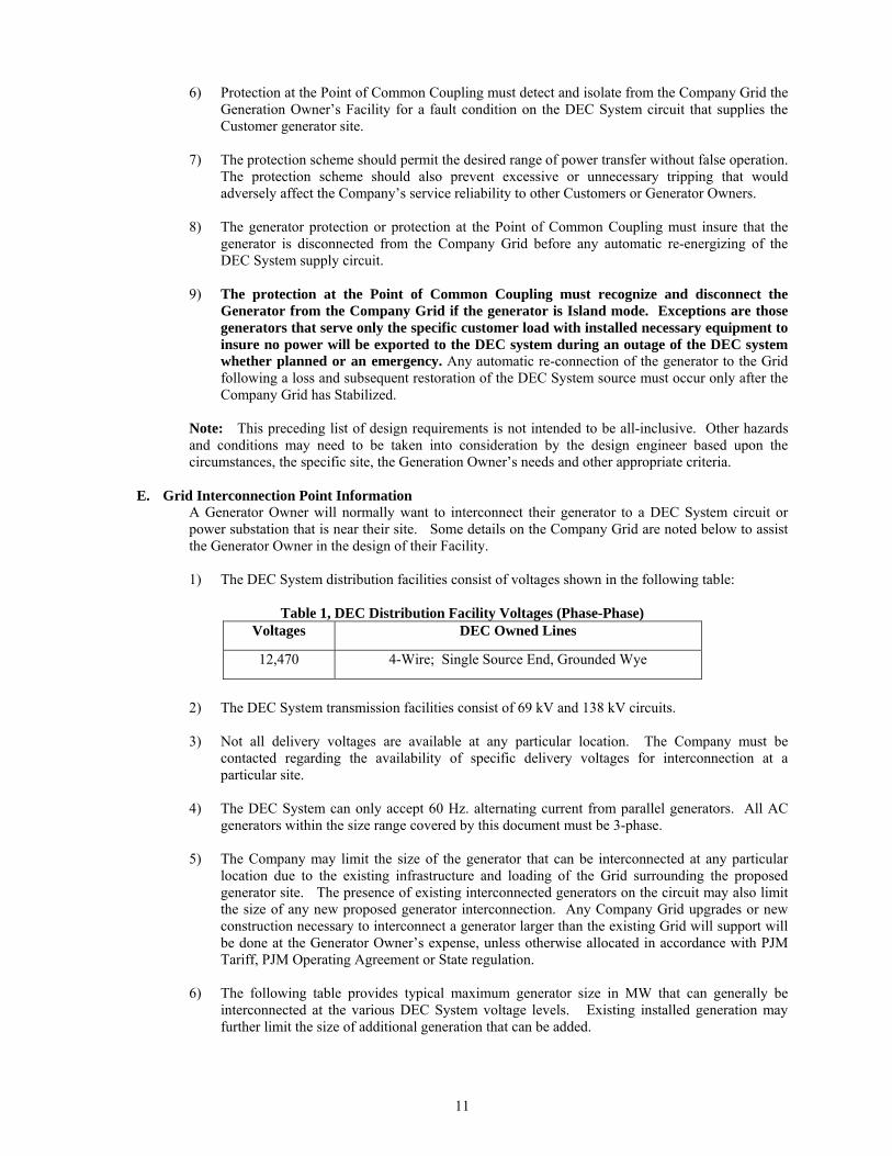
1) The DEC System distribution facilities consist of voltages shown in the following table:
Table 1, DEC Distribution Facility Voltages (Phase-Phase)
Voltages DEC Owned Lines
12,470 4-Wire; Single Source End, Grounded Wye
2) The DEC System transmission facilities consist of 69 kV and 138 kV circuits.
3) Not all delivery voltages are available at any particular location. The Company must be
contacted regarding the availability of specific delivery voltages for interconnection at a particular site.
4) The DEC System can only accept 60 Hz. alternating current from parallel generators. All AC
generators within the size range covered by this document must be 3-phase.
5) The Company may limit the size of the generator that can be interconnected at any particular location due to the existing infrastructure and loading of the Grid surrounding the proposed generator site. The presence of existing interconnected generators on the circuit may also limit the size of any new proposed generator interconnection. Any Company Grid upgrades or new construction necessary to interconnect a generator larger than the existing Grid will support will be done at the Generator Owner’s expense, unless otherwise allocated in accordance with PJM Tariff, PJM Operating Agreement or State regulation.
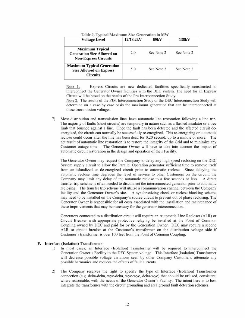
6) The following table provides typical maximum generator size in MW that can generally be
interconnected at the various DEC System voltage levels. Existing installed generation may further limit the size of additional generation that can be added.
12
Table 2, Typical Maximum Size Generation in MW Voltage Level 12/13.2kV 69kV 138kV
Maximum Typical Generation Size Allowed on
Non-Express Circuits
2.0 See Note 2 See Note 2
Maximum Typical Generation Size Allowed on Express
Circuits
5.0 See Note 2 See Note 2
Note 1: Express Circuits are new dedicated facilities specifically constructed to interconnect the Generator Owner facilities with the DEC system. The need for an Express Circuit will be based on the results of the Pre-Interconnection Study. Note 2: The results of the PJM Interconnection Study or the DEC Interconnection Study will determine on a case by case basis the maximum generation that can be interconnected at these transmission voltages.
7) Most distribution and transmission lines have automatic line restoration following a line trip.
The majority of faults (short circuits) are temporary in nature such as a flashed insulator or a tree limb that brushed against a line. Once the fault has been detected and the affected circuit de-energized, the circuit can normally be successfully re-energized. This re-energizing or automatic reclose could occur after the line has been dead for 0.20 second, up to a minute or more. The net result of automatic line restoration is to restore the integrity of the Grid and to minimize any Customer outage time. The Generator Owner will have to take into account the impact of automatic circuit restoration in the design and operation of their Facility.
The Generator Owner may request the Company to delay any high speed reclosing on the DEC System supply circuit to allow the Parallel Operation generator sufficient time to remove itself from an islandized or de-energized circuit prior to automatic reclose. Since delaying the automatic reclose time degrades the level of service to other Customers on the circuit, the Company may limit any delay of the automatic reclose to a few seconds or less. A direct transfer trip scheme is often needed to disconnect the interconnected generator prior to automatic reclosing. The transfer trip scheme will utilize a communication channel between the Company facility and the Generator Owner’s site. A synchronizing check or reclose-blocking scheme may need to be installed on the Company’s source circuit to prevent out of phase reclosing. The Generator Owner is responsible for all costs associated with the installation and maintenance of these improvements that may be necessary for the generator interconnection. Generators connected to a distribution circuit will require an Automatic Line Recloser (ALR) or Circuit Breaker with appropriate protective relaying be installed at the Point of Common Coupling owned by DEC and paid for by the Generation Owner. DEC may require a second ALR or circuit breaker at the Customer’s transformer on the distribution voltage side if Customer’s transformer is over 100 feet from the Point of Common Coupling.
F. Interface (Isolation) Transformer 1) In most cases, an Interface (Isolation) Transformer will be required to interconnect the
Generation Owner’s Facility to the DEC System voltage. This Interface (Isolation) Transformer will decrease possible voltage variations seen by other Company Customers, attenuate any possible harmonics and reduces the effects of fault currents.
2) The Company reserves the right to specify the type of Interface (Isolation) Transformer
connection (e.g. delta-delta, wye-delta, wye-wye, delta-wye) that should be utilized, consistent, where reasonable, with the needs of the Generator Owner’s Facility. The intent here is to best integrate the transformer with the circuit grounding and area ground fault detection schemes.
13
3) For all generation connected to the DEC system, the Interface (Isolation) transformer shall have a grounded wye connection to the DEC system.
4) An Interface (Isolation) Transformer that interfaces to the Company Grid with an ungrounded
connection (delta or ungrounded wye) requires a special protection scheme to detect a grounded high side conductor. (See Protection Scheme Details, Section X - C, Table 7)
5) The Interface (Isolation) Transformer must be sized to support maximum anticipated power
transfers to and from the Company Grid.
G. Power Quality Considerations 1) The Generator Owner’s Facility shall be designed and operated in such a manner that there are
no noticeable adverse impacts to system voltage, frequency, harmonics etc. 2) The parallel generation shall not cause excessive voltage flicker on the DEC System. (Voltage
flicker is defined as variations in system voltage magnitude and with duration sufficient to allow visual observation of a change in electric light source intensity.) Any flicker shall not exceed the “Borderline of Irritation” Curve, Fig. 10.3, as defined in IEEE Std. 519-2004, Recommended Practices and Requirements for Harmonic Control in Electric Power Systems. The Company reserves the right to require tighter flicker control in situations where other Customer’s or the Company’s equipment or operations (computers, instrumentation, process controls, etc.) are impacted.
3) The parallel generation could introduce harmonics distortion into the Company Grid if
equipment such as DC to AC inverters are used in the Facility. (Harmonic distortion is defined as continuous distortion of the normal 60 Hz. sine wave typically caused by non-linear loads or by inverters, measured in total harmonic distortion, THD.) Any voltage harmonic distortion shall not exceed the limitation as defined in IEEE Std. 519-2004, Recommended Practices and Requirements for Harmonic Control in Electric Power Systems, Table 11.1. The limits vary dependent on the voltage. In addition, the level of harmonic current that the Generator Owner shall inject into the Company Grid should not exceed the level specified in Tables 10.3, 10.4 and 10.5 in IEEE Std. 519-2004.
4) Any DC to AC inverter should not inject DC current greater that 0.5% of the rated inverter
capacity into the Point of Common Coupling during both normal and abnormal operation. H. Power Factor Considerations
1) For Customer owned generators seeking parallel operation through an Interconnection Request directly to PJM, the generator(s) must adhere to the power factor requirements as detailed in PJM Manual 14A, Generation and Transmission Interconnection Process, Section 5: Additional Generator Requirements and the PJM Tariff at Attachment O, Appendix 2, section 4.7. Otherwise, the power factor requirements listed below apply.
2) A parallel generator shall not adversely impact the power factor of the DEC System. The type of
generator impacts the power factor. The inverters of most DC generators are designed to operate close to unity power factor unless otherwise configured. Induction generators absorb vars from the DEC System. Synchronous generators can either absorb or produce vars thus having a varying power factor depending upon excitation control.
3) Synchronous generators shall have and maintain a minimum design capacity to operate at a
power factor between 0.85 to 1.0 lagging, i.e. supplying vars to the DEC System.
4) If the generation interconnection is not in PJM queue, synchronous generators shall generally be operated so as not to absorb vars from the DEC System unless directed by DEC. In certain cases, larger synchronous units will be required to have and maintain a minimum design capacity to operate at a power factor between 0.95 and l.0 leading, i.e. absorbing vars from the DEC System. These operating requirements will be reviewed and discussed on a case-by-case

14
basis. If the generation interconnection is in PJM queue, PJM rules will apply as noted above in (1) of this section H.
5) The dispatching authority (PJM or DEC) can request that the generator real and reactive power
output be adjusted to best meet the needs of the overall Grid.
6) Depending on the Point of Common Coupling location, the DEC System can be limited in the amount of reactive power capacity available to the Generator Owner. The Generator Owner must provide for his own reactive power requirements (via generator control, capacitors, etc.) so as to operate at no less a power factor (drawing vars from the DEC System) at the Point of Common Coupling than existed prior to the installation of the Facility. Any reactive power requirements in excess of this limit may require upgrades and/or the installation of capacitor units on the DEC System. The costs for any such upgrades will be charged to the Generator Owner. Specific purchase power arrangements, including power factor requirements, are defined in appropriate tariffs and Interconnection Agreements.
7) It is the Generator Owner’s responsibility to provide adequate mitigation equipment or controls to insure that any variation in voltage at the Point of Common Coupling does not exceed the limits defined in the tariff and by the local regulatory jurisdiction. When the generator is connected to distribution circuits at 12kV or below, the generator voltage regulation must to be set to properly coordinate with voltage regulating equipment on the DEC Power Delivery circuit.
8) For intermittent type generators such as wind and solar (photovoltaic) the generator may be
required to operate in a fixed absorbing vars power factor schedule to mitigate voltage impacts caused by power output fluctuations. If the generating facility is capable and obtains permission from DEC, it may operate in a dynamic mode to mitigate voltage impacts by dynamically controlling vars.
I. Inverter Considerations
Photovoltaic, fuel cell and wind DC generation sources will utilize inverters to convert their DC output to AC power acceptable to the Grid.
1) The Generator Owner must use a non-islanding type inverter as defined in IEEE 929 2000, IEEE
Recommended Practices for Utility Interface of Photovoltaic (PV) Systems and UL 1741, 2005, Inverters, Converters, Controllers and Interconnection System Equipment for Use with Distributed Energy Resources. (See I.3 below for possible exception.)
2) Non-islanding type inverters are inherently designed to automatically disconnect from the Grid if
the Generator Owner’s site becomes isolated from the DEC System. This type inverter also prevents the Generator owner from inadvertently supplying other Company Customers in an isolated Island situation.
3) The inverter output specifications must meet the power quality considerations detailed in Section
VIII - G. Inverters used in energy farm type installations may need to include dynamic var compensation or use other mitigating means to maintain voltage regulation at the Power of Common Coupling. Dynamic inverters that do not meet the anti-islanding provisions of IEEE 929 2000 & IEEE 1741 2005 will generally require transfer trip from the upstream protective device(s).
J. Induction Generator Considerations
Wind and other generation sources utilizing induction generators, singularly or in aggregate, could fall within the lower range of parallel generator sizes covered by this Technical Consideration document.
1) The reactive supply for induction generators may impose some design and generator size
constraints because these generators obtain their excitation from the Grid. Capacitors may have to be added either at the Generator Owner’s site or on the DEC System. (See Section VIII - H) The addition of capacitors may also cause undesirable ferroresonance. The cost to install and

15
maintain capacitors on the DEC System specifically for the generator is the Generator Owner’s responsibility.
2) Any flicker produced in the course of starting an induction generator and bringing it up to
synchronous speed (as an induction motor) must not exceed the flicker limit detailed in Section VIII - G 2.
3) The installation of capacitors for reactive supply at or near an induction generator site greatly
increases the risk that the induction machine may become self-excited if somehow isolated from the Grid. A self-excited induction generator can rapidly produce abnormally high voltages which can damage equipment on the Grid and at other Customer sites. Self-excitation is more likely where the Grid capacity and the circuit load density are both low.
4) The Generator Owner with an induction generator must include protection at their facility to
detect self-excitation operation and disconnect the generator from the DEC System.
5) By their design, induction generators can only supply fault current for a short period of time as the field flux decays rapidly on removal or decay of the source voltage.
K. Synchronous Generator Considerations
1) By their design and generally larger size, synchronous generators are capable of supporting sustained fault currents. As such, the protection scheme associated with the Point of Common Coupling must be designed to insure detection of fault conditions in the DEC System.
2) Synchronous generators are capable of operating independently irrespective of the Grid source.
They can continue to operate after being isolated from the Grid providing the load is within the generator’s capacity. Consequently, a more robust protection scheme is generally needed to detect isolation from the Grid. Transfer trip from the Company is generally required.
3) Sufficient generator reactive power control capability shall be provided to withstand normal
voltage changes on the DEC System. L. Interval (Revenue) Metering Considerations
For Customer owned generators seeking parallel operation through an Interconnection Request directly to PJM, the generator(s) must adhere to the metering requirements as outlined in PJM Manual 01, Control Center and Data Exchange Requirements, Section 5: Metering Requirements and PJM Tariff, Attachment O, Appendix 2, section 8. Additional DEC metering requirements are detailed below and also apply to PJM queue projects, except as noted.
The requirements for each parallel generator installation will be reviewed and revised on a case-by-case basis. Listed below are the standard requirements for generator Interval Metering. The Company, however, reserves the right to specify the required interval metering equipment for each paralleled generator site.
1) All paralleled generator Facilities shall be metered in accordance with applicable tariffs and
specifications provided in approved Company publications. (Note: Does not apply to PJM generation queue projects.)
2) An Interval (Revenue) Meter must be located at each Point of Common Coupling. The Interval
Meter will record MW-Hour and MVAR-Hour input and output.
3) The Generator Owner may net retail site load behind a single meter at the Point of Common Coupling except: a) A separate Interval Meter is required for each generator if the generator or aggregate
generation is greater than 2 MW. b) In cases where the generation is served under a generator “Standby Tariff”. Under this
tariff, each generator must have a separate Interval Meter to record MW-Hour and MVAR-Hour input and output. (Note: Does not apply to PJM queue projects.)
16
4) Generator site auxiliary loads that are not measured by the generator Interval Meter will require a
separate meter. 5) The Generator Owner shall supply a telephone line for the Interval Meter data recorder which
allows the Company to dial up and retrieve the Interval Meter data remotely. Specific requirements will be determined on a case-by-case basis.
6) Unless otherwise mutually agreed upon by the Company and Generator Owner, the Company
shall install and own all Interval Metering equipment at the Point of Common Coupling and on the generator(s). The Generator Owner shall pay the Company the initial costs to procure, install, test and startup the metering and associated related equipment. Thereafter, the metering equipment shall be owned, operated and maintained by the Company. (These provisions are subject to possible modification by PJM, regulatory commissions or applicable tariffs. PJM allows Generator Owners to install, own, operate and maintain the Interval Metering (i.e. PJM “Metering Equipment”)) The Company and the Generator Owner may agree to have the Generator Owner install the metering PTs (potential transformers) and CTs (current transformers) within the Generator Owner’s switchgear equipment.
7) All metering shall comply with ASNI and Company technical requirements (including meter
model, options & programming). The Point of Common Coupling and generator Interval Meters shall be bi-directional so that power deliveries (including reactive) to and from the Generator Owner’s site can be separately recorded. The Point of Common Coupling Interval Meter shall be equipped with detents to prevent reverse registration.
8) The Generator Owner may, at its sole option and cost, install or have the Company install
additional metering equipment to meet any special needs that the Generator Owner may have. M. Monitoring, Control and Remote Telecommunication Considerations
For Customer owned generators seeking parallel operation through an Interconnection Request directly to PJM, the generator(s) must adhere to the monitoring, control and remote telecommunication requirements as outlined in PJM Manual 01, Control Center and Data Exchange Requirements and PJM Manual 14D, Generator Operational Requirements. Additional DEC monitoring, control and telecommunication requirements are detailed below and also apply to PJM queue projects, except as noted. Since parallel generators, particularly the larger units, have a direct impact on the overall operation and performance of the Grid, it is important that the Company monitor and have emergency trip control of the generator interface breaker(s). The requirements for each parallel generator installation will be reviewed on a case-by-case basis.
1) Telemetered data for each meter required in preceding Section VIII.L shall be telemetered to
DEC’s designated Control Center via a dedicated data circuit (See M.3 for an exception.)
2) The Generator Owner shall purchase and install a Remote Terminal Unit (RTU) of a DEC approved vendor to enable the Company and, if required, PJM to monitor the status of the data points at the Generator Owner’s site and to control certain breakers, if required. This RTU shall utilize DNP 3.0 protocol, or other such protocol compatible with the existing Supervisory Control System at the Company. Required data points are listed in M.6 below. In addition, the Generator shall supply a data link for transmitting the telemetry data between the Generator Owner’s RTU and the appropriate DEC Control Center.
3) A generator or aggregate generation of 10 MW or less behind a Point of Common Coupling that
is exporting energy and/or capacity to PJM may send telemetry data for the Point of Common Coupling and generator meters to PJM via an internet option in lieu of sending telemetry directly to DEC. The Generator Owner must authorize PJM to resend the telemetry data to DEC. DEC may still require direct telemetry under special circumstances. The required data points are listed in M.6 below. PJM should be contacted for detailed information on the internet option.

17
4) Specific data points will vary depending upon on the size of the interconnected generation. Analog telemetry and status indication points are listed below in M.6. In addition, certain control functions may be required to allow remote dispatch of generation or for isolating the generation from the DEC System in the event of a System Emergency. Specific monitoring and control requirements will be determined on a case-by-case basis.
5) Remote tripping capability by DEC System Operations is required for all generator
interconnections larger than 2 MW or interconnected at 12.47 kV or higher voltage, as noted below in M.6.
6) Telemetry and control requirements by generator capacity:
Units 25 kw to 2 MW Capacity Generation MW and MVAR Output, MW-Hours and MVAR-Hours for each generator if Standby Tariff applies.
Units Greater Than 2 MW to 10 MW Capacity a) Point of Common Coupling MW, MVAR, MW-Hours, MVAR-Hours, Amp Flow on
each Point of Common Coupling. b) Generation Bus and Point of Common Coupling Bus Voltages. c) Status indication of generator breaker(s) and Point of Common Coupling breaker/
switch. d) Remote generator breaker tripping capability by DEC System Operations. e) Generation MW and MVAR Output, MW-Hours and MVAR-Hours for each generator
if Standby Tariff applies. The Generator Owner’s RTU shall connect directly to DEC. For PJM projects, the required telemetry data may be re-transmitted to DEC. If data is retransmitted by PJM, the Generator Owner shall grant PJM permission to retransmit the data to DEC.
Units Greater Than 10 MW to 50 MW Capacity a) MW and MVAR Output, MW-Hour and MVAR-Hour for each generator. b) MW, MVAR, Amp Flow, MW-Hour and MVAR-Hour on each Point of Common
Coupling. c) Generation Bus and Point of Common Coupling Bus Voltages. d) Frequency at the Point of Common Coupling. e) Status indication of generator breaker(s) and Point of Common Coupling breaker. f) Remote generator breaker tripping capability by DEC System Operations. The Generator Owner’s RTU shall connect directly to DEC.
Units Greater Than 50 MW a) MW and MVAR Output, MW-Hour and MVAR-Hour for each generator. b) MW and MVAR load of generator auxiliaries and Facility. c) MW, MVAR, Amp Flow, MW-Hour and MVAR-Hour on each Point of Common
Coupling. d) MW, MVAR, Amp Flow through the Interface Transformer if site loading causes the
flow through the Interface Transformer to be different than the generator. e) Generation Bus and Point of Common Coupling Bus Voltages f) Frequency at the Point of Common Coupling. g) Status indication of generator breakers and all substation breakers. h) Remote generator breaker tripping capability by DEC System Operations. The Generator Owner’s RTU shall connect directly to DEC.
Notes:
1. The Generator Owner shall contact PJM directly and review PJM documents to insure compliance with all the PJM RTU monitoring/control requirements for their proposed site. 2. The Company will allow multiple generator unit data to be combined into a single unit for Facilities not exceeding 10 MW total for all units.

18
N. Event Recording Considerations 1) The Generator Owner shall purchase and install recording equipment to monitor the performance
of their protection and control equipment for those parallel generator sites interconnected with the DEC System at a voltages level of 69kV and above.
2) The Company reserves the right to specify the voltages, currents, device status, etc. to be monitored and recorded by this event recording equipment.
3) Event information may be recorded by event record features internal to microprocessor type
protective relays, by separate digital fault/event recorders or by a combination of these two methods.
4) When a digital fault/event recorder is installed, the Company will specify a manufacturer and
type to insure compatibility with other digital fault/event recorders in the DEC System.
5) The Company shall have remote access to any recorded information for use in analyzing the performance of the overall electric Grid.
6) The Generator Owner will supply a dialup telephone line for the event recording equipment for
remote access of the data.
7) RFC (ReliabilityFirst Corporation) has additional fault recorder requirements for generator sites interconnected at 200kV or above and having either a single generator 250 MVA or greater or an aggregate generating plant capacity of 750 MVA or greater. The prospective Generator Owner should review RFC Standard PRC-002, FRC-01, 5/14/09, Disturbance Monitoring and Reporting Requirements. NERC Standards are routinely modified. It is the responsibility of Generator Owner to be knowledgeable of an in compliance with applicable NERC/RFC Reliability Standards.
8) Digital fault recorders should be time synchronized to a reference traceable to the National
Institute of Standards and Technology (NIST).
IX. Performance Considerations
A. General 1) The interconnection of parallel generation with the DEC System is permissible only if the system
voltage, frequency and current flow at the Point of Common Coupling are within normal limits. Parallel operation must cease immediately and automatically for abnormal voltage, frequency, or current flow as defined below.
2) Parallel operation must also cease automatically for operation outside the power quality
limitations detailed in Technical Design Considerations, Section VIII - G.
B. Voltage Limits 1) The Generator Owner’s equipment shall be operated in such a manner that the voltage levels on
the Company’s Grid remain within the operating limits defined by ANSI C84.1 and within the limits defined by tariff and local regulatory jurisdiction.
2) The generator must immediately and automatically cease parallel operation and disconnect from
the DEC System if the voltage at the Point of Common Coupling exceeds the limits defined following:

19
Table 3, Voltage Trip Points DC Generating Systems with
Non-Islanding InvertersInduction and Synchronous Generators
All Sizes a) Trip in 0.16 Second for V < 50% b) Trip within 2.0 Seconds for
50% V < 88% c) Trip within 2.0 Seconds for
110% < V < 120% d) Trip in 0.16 Second for V ≥ 120% Note: Voltage and time delay set points taken from IEEE Std. 1547-2008 & UL 1741 – 2005
a) Trip in 0.16 Second for V < 50% b) Trip in 2.0 Seconds for 50 ≤ V < 88% c) Trip in 1.0 Second for 110 < V < 120% d) Trip in 0.16 Second for V 120% Note: Specific voltage and time delay set points vary for each installation. Typical set points from IEEE 1547 are shown above and are applicable for small generators. IEEE Std. 1547-2008
Notes:
i. Trip time refers to the time between when the abnormal voltage condition occurs and the generator being disconnected from the Company Grid.
ii. Three-phase voltage sensing shall be used. iii. The voltages must be sensed on the high side of any Interface (Isolation) Transformer if
the high voltage winding is ungrounded. Such a scheme is necessary to rapidly detect severe over voltages that occur for a grounded high side conductor being energized from an ungrounded generation source. These high voltages can quickly cause catastrophic failure of lightning arresters and lead to other equipment insulation failures.
iv. Exceptions to these limits may be granted or required for bulk synchronous generators with a contractual obligation and authority to supply other Customer load in an Island mode arrangement. These generators must install appropriate equipment to control and stabilize voltage within the Island.
3) The Generator Owner may reconnect to the Grid when the system voltage returns to normal range
and the Grid is Stabilized. Reconnection approval shall be requested from the Company Control Center. NEM generators and other generators 2 MW or less are generally exempt from receiving reconnection approval.
C. Frequency Limits 1) The generator must immediately and automatically cease parallel operation and disconnect from
the DEC System if the operating frequency exceeds the limits defined below:
Table 4, Frequency Trip Points DC Generating Systems with
Non-Islanding Inverters Induction/Synchronous Generators
Non PJM Market <20 MW Synchronous Generators
In PJM Market or 20 MW> a) Trip in 0.1 Second for
F < 59.3 Hz. b) Trip in 0.1 Second for
F > 60.5 Hz.
Note: Set points taken from IEEE Std. 1547 - 2008. & UL 1741 - 2005
a) Trip in 0.16 Second for F < 57.0 Hz. b) Trip in 0.16 - 300 Second(s) for 57.0 < F < 59.8 Hz. c) Trip in 0.16 Second for F > 60.5 Hz. Note: Frequency and time delay set point for 57.0-59.8 Hz. will be determined for each specific installation. IEEE Std. 1547-2008.
Frequency and time delay set points will be determined for each specific installation. Set points will be selected to: a) Coordinate with area under frequency
load shedding programs. b) Meet RFC under frequency
guidelines in PRC-006-RFC-01, Automatic Under Frequency Load Shedding Requirements.
c) Meet the frequency operational requirements in PJM Manual 14D, Generator Operational Requirements, Section 7, Generator Operations.
Notes: i. Trip time refers to the time between when the abnormal frequency condition occurs and the
generator being disconnected from the Company Grid.
20
ii. Synchronous Generators less than 20 MW whose output is netted with peak load (net system load reducer) to calculate PJM under frequency load shedding needs, will also have to meet frequency requirements for PJM Market generators.
iii. PJM Frequency requirements are to provide uniformity across the entire Grid and to insure that all generator units will remain online until the frequency limits are reached.
iv. PJM can grant an exception to the trip frequency requirement if warranted.
2) The Generator Owner may reconnect to the Grid when the system frequency returns to normal range and the Grid is Stabilized. Reconnection approval shall be requested from the Company Control Center. NEM generators and other generators 2 MW or less are generally exempt from receiving reconnection approval.
D. Synchronization
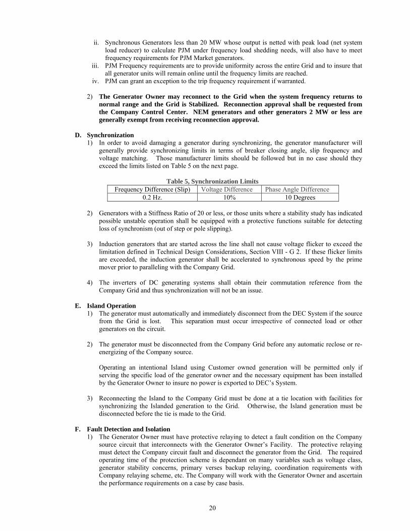
1) In order to avoid damaging a generator during synchronizing, the generator manufacturer will generally provide synchronizing limits in terms of breaker closing angle, slip frequency and voltage matching. Those manufacturer limits should be followed but in no case should they exceed the limits listed on Table 5 on the next page.
Table 5, Synchronization Limits
Frequency Difference (Slip) Voltage Difference Phase Angle Difference 0.2 Hz. 10% 10 Degrees
2) Generators with a Stiffness Ratio of 20 or less, or those units where a stability study has indicated
possible unstable operation shall be equipped with a protective functions suitable for detecting loss of synchronism (out of step or pole slipping).
3) Induction generators that are started across the line shall not cause voltage flicker to exceed the
limitation defined in Technical Design Considerations, Section VIII - G 2. If these flicker limits are exceeded, the induction generator shall be accelerated to synchronous speed by the prime mover prior to paralleling with the Company Grid.
4) The inverters of DC generating systems shall obtain their commutation reference from the
Company Grid and thus synchronization will not be an issue.
E. Island Operation 1) The generator must automatically and immediately disconnect from the DEC System if the source
from the Grid is lost. This separation must occur irrespective of connected load or other generators on the circuit.
2) The generator must be disconnected from the Company Grid before any automatic reclose or re-
energizing of the Company source.
Operating an intentional Island using Customer owned generation will be permitted only if serving the specific load of the generator owner and the necessary equipment has been installed by the Generator Owner to insure no power is exported to DEC’s System.
3) Reconnecting the Island to the Company Grid must be done at a tie location with facilities for synchronizing the Islanded generation to the Grid. Otherwise, the Island generation must be disconnected before the tie is made to the Grid.
F. Fault Detection and Isolation
1) The Generator Owner must have protective relaying to detect a fault condition on the Company source circuit that interconnects with the Generator Owner’s Facility. The protective relaying must detect the Company circuit fault and disconnect the generator from the Grid. The required operating time of the protection scheme is dependant on many variables such as voltage class, generator stability concerns, primary verses backup relaying, coordination requirements with Company relaying scheme, etc. The Company will work with the Generator Owner and ascertain the performance requirements on a case by case basis.

21
2) In cases where clearing time from the Generator Site is critical and/or when a high speed auto
reclose is needed on the source circuit, transfer trip from the Company end of the circuit to the Generator Owner’s site will be required.
3) For a fault condition within the Generator Owner’s Facility, the Generator Owner must have
protective relaying to detect and isolate the fault from the DEC System. The required clearing time of the Facility’s protection schemes is dependent on many variables such as voltage class and the operating time of any Company protection schemes that reach into the Facility. The Company will review the proposed operating time of the Facility’s protection schemes and ascertain the performance requirements on a case by case basis.
G. Closed Transition Switching Installations
Some privately owned generation may be paralleled only momentarily with the DEC System during part of a source or load transfer sequence. Generators used primarily for load reduction or emergency power are sometimes operated in this manner.
1) At the time of momentary parallel operation, these installations must meet the voltage, frequency
and synchronization requirements outlined in preceding Sections IX - B, C, and D. The synchronizing may be manual for generators up to 10 MW if the closed transition is manually initiated. Otherwise, the synchronizing should be automatic.
2) The transition scheme must have an additional safeguard to limit the amount of time the generator
is paralleled with the Grid. The scheme shall trip the generator if the closed transition mode remains in effect longer than some predetermined time DEC to which the Generator Owner is requesting interconnection will determine the allowable time span for parallel operation of the generator.
X. Protection Scheme Details
A. General 1) The protection schemes described in this section are intended to be typical for illustration
purposes and not specific design requirements for any particular site. They are intended to guide the proposed Generator Owner and provide basic information on the types of protection schemes necessary for generator Parallel Operation.
2) Protective relays, wherever possible, shall be microprocessor type with integral trip record and
fault recording, self-checking and remote communications. Remote communications should be provided through a digital switching device to allow a single communication line to service multiple protective relays.
3) All protective relays must have the desired sensitivity and speed for its intended application and
be of utility grade. The Company can provide feedback to the Generator Owner in this regard.
4) All equipment, lines and busses operating at 69kV and above shall be protected by two independent protective schemes.
5) Primary and backup protection schemes shall be supplied via independent current/potential
circuits and independently protected DC control circuits.
6) DC circuits supplying protective relaying schemes shall be continuously monitored and fused separately from any other DC control circuits. Loss of any control power bus including DC trip and close busses of each breaker shall also be monitored and alarmed to a manned location so that corrective action can be taken. Relay failure alarms shall be handled in a similar manner.

22
7) Generator units selling into the PJM marketplace, or interconnected at 69kV and above, must meet the protection requirements detailed in the PJM Protective Relaying Philosophy and Design Standards document.
8) All protective relay systems, equipment, design, operation and maintenance shall be in
accordance with all applicable Federal, State and Local requirements, National and Regional Reliability Criteria and Industry Recognized Standards and Guidelines. References to such requirements may be found in Section XIII of this document. The listing is not intended to be all-inclusive.
B. Interface (Isolation) Transformer Protection
Typical protection schemes for various size Interface Transformers are illustrated below.
Table 6, Interface Transformer Protection Up to 10 MVA 10 – 50 MVA Greater than 50 MVA
3 Phase protection device (12kV or 69kV only)
Transformer Differential Fault Pressure Time/Inst. Over Current
Transformer Primary Differential
Transformer Backup Differential
Fault Pressure Time/Inst. Over Current Over Excitation
Notes:
i. For transformers needing two differential protection schemes, one of the differential schemes may also include the generator.
ii. The location of the transformer over current relaying may be dependent on the transformer connections.
iii. Generators with a fuse protected Interface (Isolation) Transformer must include protection to detect an open fuse condition.
C. Interconnection Line Protection
The protection applied to a line terminal at the Generator Owner’s site that interconnects the privately owned generator with the DEC System will vary depending on the voltage class and existing line relaying scheme at the DEC end(s). Typical protection schemes for various voltage interconnection lines are provided below. The actual schemes used will vary for each specific site.
Table 7 Typical Line Terminal Protection Schemes
Line Voltage Class
Possible Line Protection Schemes
12kV Phase & Ground Over current (May need to be directional) 3-Phase to Ground Connected Under Voltage & Over Voltage
(For line terminating in delta or ungrounded wye connected transformer)
69kV Phase & Ground Directional Over current Phase & Ground Distance Pilot (DCB, POTT, PUTT, DTT) Phase & Ground Step Distance Backup 3-Phase Overvoltage (For line terminating in delta or ungrounded wye
connected transformer)
138kV Phase & Ground Distance Pilot (DCB, POTT, PUTT, DTT) Phase & Ground Step Distance Backup Direct Transfer Trip Send/Receive

23
Notes: 1) Generators that can go unstable due to delayed fault clearing if line pilot protection
scheme fails will require two independent high speed pilot schemes, with independent communication channels.
2) DCB is Directional Comparison Blocking 3) POTT is Permissive Overreaching Transfer Trip 4) PUTT is Permissive Under Reaching Transfer Trip. 5) DTT is Direct Transfer Trip
D. Generator Isolation Detection Schemes
1) Under/over frequency and under/over voltage schemes can be used to detect the fact that the generator is Islanded with load (and possibly other generation) and needs to be disconnected from the DEC Grid. These schemes are effective where there is a significant mismatch between load and generator rating. IEEE Std. 1547-2008, Footnote 12, requires that the load to generation mismatch be 3 to 1. The detection must also occur within 2 seconds of the formation of an island. (See also Performance Considerations, Sections IX – B2 and C1)
2) Under/over frequency and under/over voltage detection becomes less reliable when the Islanded
load is more closely matched to the generator capacity so that the resulting voltage and frequency is at or very near normal. In these cases, direct transfer trip from the DEC System to the Generator Owner’s site will be necessary.
3) Generators selling into the PJM marketplace that have their under frequency trip point set to meet
PJM under frequency operational requirements (such as 57.5 Hz. for 5 Seconds) essentially removes under frequency sensing as a sensitive means to detect isolation. In this event, other protective measures, such as transfer trip, will be required.
4) Generators using dynamic inverters to regulate voltage at the Point of Interconnection generally
will not conform to the requirements of IEEE 1547-2008 and thus will require transfer trip from the upstream protective device(s).
5) Generally, combinations of different protection schemes are necessary to be 100% effective and
to provide a level of redundancy. 6) In cases where a transfer tripping scheme is needed to ensure isolation detection, the failure of the
transfer trip scheme or communication channel will require that the generator automatically disconnect from the DEC until the transfer trip scheme is restored.
E. Generator Protection Schemes
1) The protection schemes on generators will become more complex as the size of the generator unit increases. In addition, those generators selling into the PJM marketplace will require specific protection as required by PJM. The PJM Relay Subcommittee Protective Relaying Philosophy and Design Standards should be consulted.
2) Multi-function microprocessor relays can be used to provide several generator protection
functions. However, a second multi-function relay (preferably from another manufacturer to avoid a common failure mode or defective algorithm) is necessary to provide for a relay failure. Alternatively, the generator could be immediately and automatically tripped off line upon a relay failure alarm and remain off line until the relay is repaired. This arrangement, however, may jeopardize the Generator Owner’s ability to sell firm capacity into the PJM marketplace.
3) The Generator Owner should consult the generator manufacturer and national standards to
develop the appropriate protection for each generator installation. National standards include C37.102-2006 IEEE Guide for AC Generator Protection and C37.101-2006 IEEE Guide for Generator Ground Protection.
4) Some typical protection schemes for various size generators are noted in Table 7 on the following
page. The actual schemes required for each site could vary from these representative samples.

24
Table 8, Typical Generator Protection Schemes DC Generating Systems
With Non-Islanding Inverters
Induction/Synchronous Generators
Up to 10 MW
Synchronous Generators
10MW up to 50 MW
Synchronous Generators
50 MW & Above
Over/Under Voltage
Over/Under Frequency
(This preceding protection is integral to the Non-Islanding Inverter.) DC Over current
Over/Under Voltage Over/Under
Frequency Directional Power (watt / var) Phase Over current Ground Over
current Negative Sequence
Over/Under Voltage
Over/Under Frequency
Differential Stator Ground Loss of Field Anti-Motoring Negative Sequence Voltage
Controlled. Over current
Over/Under Voltage Over/Under Frequency Primary Differential Back Up Differential 100% Stator Ground Back Up Stator Ground Generator Lead Protection Primary Loss of Field Back Up Loss of Field Field Ground Anti-Motoring Negative Sequence Voltage Controlled Over
current or Distance Backup Breaker Flashover Protection During Unit Start
Up & Shut Down Accidental Energization Out of Step Protection Synchronizing Check
(Ref. Appendix A)
XI. Typical One-Line Diagrams The One-Line Diagrams in Appendix E are intended to be typical or representative samples of various types and sizes of generation Facilities that are connected to and operate in parallel with the DEC System and do not purport to cover every possible case. Each site will have to be specifically designed taking into account the unique characteristics of each installation, the specific location of the Point of Common Coupling and the operating and contractual requirements for that site. Additional PJM and RFC requirements may also apply. The listed voltages on the diagrams represent nominal values. The actual voltage is dependent on the interconnection location on the DEC circuit.
Comments:
a) On generators with primary and backup differentials, one differential may also cover the unit step up transformer.
b) Loss of synchronism (out-of-step) protection is necessary where stability studies have shown this protection to be needed.
c) Ancillary protection schemes such as breaker failure are also required.
25
XII. Interconnection Application for non-PJM Generation Interconnection Projects
A. For non PJM generation interconnections, the proposed Generator Owner shall submit an Interconnection Application to the DEC for approval to connect and operate a generating unit in parallel with the DEC Grid. This application should be made as far in advance as possible of the tentative planned in service date. In general, the larger the proposed generating unit, the more lead time is needed to review all aspects of the interconnection and to finalize the Facility design. In addition, those Generator Owners who plan to sell into the PJM market must also submit the necessary applications to PJM and enter the PJM application queue. (The PJM application process is outside the scope of this document and the proposed Generator Owner will have to contact PJM directly on these issues. Information can also be found on the PJM website, www.pjm.com)
B. Early application submission can also be cost advantageous to the proposed Generator Owner. The
DEC System near the proposed generator site may require extensive and costly upgrades in order to accommodate the output of the generator. These upgrade costs may make the proposed site undesirable for the project. Early application should make this adverse information known before the proposed Generator Owner has made extensive design and site purchase/work expenditures.
C. Early application submission is also advantageous to DEC and assists DEC in meeting the Generator
Owner’s time schedule. DEC will have to assign resources, do engineering and order material necessary for any Grid upgrades. The earlier this process is started, the easier it is for DEC to meet the Generator Owner’s proposed in service date.
D. The Generator Owner shall complete an Interconnection Application Form and supply as much
information as possible. It is realized that some information will probably not be available at the time of the initial application submission. However, the Generator Owner should supply as much information and details as possible and forward other necessary information as soon as it becomes available. For non PJM generation interconnections, the forms in Appendix B to this document should be used. For PJM queue projects, refer to the PJM Tariff for application forms and requirements.
E. For non PJM generation interconnections, a One-Line Diagram for the entire proposed Facility shall
accompany the Interconnection Application. The diagram shall include details on the connection and rating of all equipment and show all protective schemes. In addition, transformer and generator impedance characteristics and dynamic modeling data must be submitted. (See Appendix B)
F. Details on how the proposed Facility is to be operated and the anticipated range of power to be
exported into DEC Grid should be included with the Interconnection Application. G. DEC reserves the right to request additional data, information details and drawings necessary to fully
review the proposed Facility and to insure coordination of all equipment with DEC Grid. H. For non PJM generation interconnections, following submission of the Interconnection Application,
DEC, the Generator Owner and the Generator Owner’s technical consultants will institute a series of meetings to review and discuss the proposed Facility. The comments and feedback from DEC at these meetings will enable the Generator Owner to finalize his design and operating requirements. For PJM queue projects, the PJM interconnection process must be followed.
I. In addition to reviewing the data, drawings and specifications provided by the Generator Owner, DEC
may elect to physically inspect the Generator Owner’s site during and after construction to insure adherence to the information supplied.
J. All protection, control schemes, metering and RTU operations must be functionally tested and
operating correctly before DEC can approve the Interconnection. K. DEC reserves the right to witness testing of the Generator Owner’s protection and control schemes
and to request copies of any test data/results. In witnessing any testing, DEC assumes no liability as the full responsibility of Facility operation and protection rests with the Generator Owner.

26
L. The Generator Owner can interconnect with DEC Grid and commence parallel operation only after
DEC has provided written approval to interconnect.
XIII. References The references and standards listed below can provide technical requirements, support and insight into the safe, reliable interconnection of distributed and parallel generation with the DEC systems. These references should be reviewed by those individuals and/or firms contemplating parallel operation of generation with DEC for applicability to their installation. This listing is not intended to be all-inclusive. In cases where a referenced document has been updated, the most recent version of the document should be used. NFPA 70, National Electric Code (NEC)
ANSI Std. C84.1-1995, Electric Power Systems and Equipment – Voltage Ratings ANSI/IEEE Std. C37.1-2007, IEEE Standard for SCADA and Automation Systems IEEE 100-2000, IEEE Authoritative Dictionary of IEEE Standard Terms
IEEE Std. 141-1993, IEEE Recommended Practice for Electric Power Distribution for Industrial
Plants (IEEE Red Book)
IEEE Std. 242-2001, IEEE Recommended Practice for Protection and Coordination of Industrial and Commercial Power Systems (IEEE Buff Book)
IEEE Std. 493-2007, IEEE Recommended Practice for Design of Reliable Industrial and Commercial
Power Systems (IEEE Gold Book) IEEE Std. 519-1992, Second Printing 2004, IEEE Recommended Practice and Requirements for
Harmonic Control in Electric Power Systems IEEE Std. 929-2000, IEEE Recommended Practice for Utility Interface of Photovoltaic (PV) Systems IEEE Std. 1001-1988, IEEE Guide for Interfacing Dispersed Storage and Generation Facilities with
Electric Utility Systems IEEE Std. 1021-1988, IEEE Recommended Practices for Utility Interconnection of Small Wind
Energy Conversion Systems
IEEE Std. 1159-1995 (Reaff. 2001), IEEE Recommended Practice for Monitoring Power Quality IEEE Std. 1547-2003 (Reaff. 2008), IEEE Standard for Distributed Resources Interconnected with
Electric Power Systems
IEEE Std. 1547.1-2005, IEEE Standard Conformance Test Procedures for Equipment Interconnecting Distributed Resources with Electric Power Systems
IEEE Std. 1547.2-2008, IEEE Application Guide for IEEE 1547
IEEE Std. 1547.3-2007, IEEE Guide for Monitoring, Information Exchange and Control of
Distributed Resources Interconnected with Electric Power Systems.
IEEE Std. 1547.4/D10.0 IEEE Draft Guide for Design, Operation and Integration of Distributed Resource Island Systems with Electric Power Systems.
IEEE C2, National Electric Safety Code (NESC)

27
IEEE Std. C37.2-2008, IEEE Standard for Electric Power System Device Function Numbers,
Acronyms and Contact Designations. IEEE Std. C37.90-2005, IEEE Standard for Relays and Relay Systems Associated with Electric Power
Apparatus IEEE Std. C37.90.1-2002, IEEE Standard Surge Withstand Capability (SWC) Tests for Protective
Relays and Relay Systems Associated with Electric Power Apparatus. IEEE Std. C37.91-2008, IEEE Guide for Protecting Power Transformers IEEE Std. C37.93-2004, IEEE Guide for Power System Protective Relay Applications of Audio Tones
over Voice Grade Channels IEEE Std. C37.95-2002, IEEE Guide for Protective Relaying of Utility Consumer Interconnections IEEE Std. C37.101-2006, IEEE Guide for Generator Ground Protection IEEE C37.102-2006, IEEE Guide for AC Generator Protection IEEE C37.103-2004, IEEE Guide for Differential and Polarizing Relay Circuit Testing
IEEE C37.104-2002, IEEE Guide for Automatic Reclosing of Line Circuit Breakers for AC
Distribution and Transmission Lines IEEE C37.106-2003 (Reaff. 2009), IEEE Guide for Abnormal Frequency Protection of Power
Generating Plants IEEE Std. C37.110-2007, IEEE Guide for the Application of Current Transformers Used for
Protective Relaying Purposes IEEE Std. C37.113-1999 (Reaff. 2004), IEEE Guide for Protective Relaying Applications to
Transmission Lines
IEEE C37.230-2007, IEEE Guide for Protective Relaying Applications to Distribution Lines
IEEE C37.234-2009, IEEE Guide for Protective Relay Applications for Power System Busses IEEE Std. C57.13.1-2006, IEEE Guide to Field Testing of Relaying Current Transformers
IEEE Std. C57.13.2-2005, IEEE Standard Conformance Test Procedures for Instrument Transformers IEEE Std. C57.13.3-2005, IEEE Guide for the Grounding of Instrument Transformer Secondary
Circuits and Cases UL 1741-2005, Underwriters Laboratories, Inc. Inverters, Converters, Controllers and
Interconnection System Equipment for Use with Distributed Energy Resources. PJM Protective Relaying DEC Philosophy and Design Standards
PJM Relay Testing and Maintenance Practices
PJM Transmission Substation and Line Design, Application and Maintenance Guidelines NERC & RFC Planning Standards

Appendix A DEC Power Delivery
Generator Protection Guidelines For Units 50 MW and Above

Appendix – A 1
DEC Power Delivery Generator Protection Guidelines
For Units 50 MW and Above The following discussion and guidelines are intended to be a basis for considering what protection to apply to both new units and those being upgraded. The PJM Relay Subcommittee Protective Relaying Philosophy and Design Standards document is the basis for these guidelines. Some specific protection applications may also be required as the result of consultation with the generator manufacturer. Generator protection, like that on transmission lines, buses and transformers should be designed for reliability. This means an artful balance of dependability and security. Dependability is a measure of the protective relaying systems certainty to trip when required and security a measure of the ability not to trip falsely. The balancing of these two requirements involves consideration of independent ac current and voltage sources to the front line and backup relay schemes. Also independently protected dc control circuits should be used with the front-line and backup relay schemes. In those cases which follow, if the need for both front-line and backup relays is not defined, one protective scheme will be adequate. 1.0 Generator Stator Fault Protection
1.1 General Consideration Generator stator faults are very serious and cause costly damage. Because of the obvious importance of generators, the fault must be detected and cleared in the least amount of time possible. Because of the stored rotating energy of the generator, damage may occur after all the required breakers have been tripped.
1.2 Phase Fault Protection
Use a front-line current differential relay scheme and an independent backup differential scheme with independent current sources and independently protected dc control circuits. Each of these schemes should trip the generator breakers, excitation system and turbine valves.
1.3 Ground Fault Protection
High impedance grounding of generators is an accepted industry practice. This is done to limit the magnitude of ground fault current. Ground fault protection should include two independent relay schemes, employing independent current or voltage sources and independently protected dc control circuits. Each scheme should trip the generator breakers, excitation system and turbine valves.
2.0 Generator Rotor Field Protection
The generator rotor field winding is ungrounded. One ground on this field will not effect the generator's operation. The first ground, however, greatly increases the likelihood of a second ground occurring, causing imbalances and overheating. Generators should be equipped with rotor ground fault protection which will alarm only. Upon receipt of this alarm, the generator's load should be reduced to zero and the generator shut down as quickly as possible.

Appendix – A 2
3.0 Generator Abnormal Operating Conditions
3.l Loss of Field
Loss of field (loss of excitation) will result in loss of synchronism. Detection of this loss of field is usually done with impedance type relays. A front-line and independent backup scheme is required with each providing a simultaneous trip of the generator breakers, excitation system and turbine valves.
3.2 Unbalanced Currents
Unbalanced, or negative sequence currents, are the result of unbalanced loading. This could be the result of one phase open or unbalanced system faults which are not cleared properly. The unbalanced currents themselves cause generator rotor overheating. Protection requires a negative sequence time over current relay with sensitivity sufficient to detect unbalanced conditions exceeding the continuous rating of the generator. The protection should initiate an alarm at one level and a unit trip at a higher level.
3.3 Loss of Synchronism
Loss of synchronism, out of step and pole slipping are all synonymous and can result from transients, dynamic instability or loss of excitation. This condition can be damaging to the unit. Detailed stability studies can determine if out of step protection is required. As a rule, if an impedance swing enters the generator or step up transformer impedance, out of step protection is necessary. When out of step protection is required, the generator should be tripped within the first slip cycle.
3.4 Over Excitation
Excessive flux (over excitation) in the generator core can cause rapid overheating. Volts/Hertz is a measure of this condition. Two independent schemes should be used, each providing protection for the volts/hertz rating of the generator. An initial alarm followed by a simultaneous trip of the generator breakers, excitation system and turbine valves is recommended.
3.5 Reverse Power (Anti-Motoring)
Generator motoring is caused by the lack of energy supplied to the prime mover resulting in the electrical system driving the machine as a motor. Synchronous motoring will not damage the generator, but will cause damage to the prime mover. Anti-motoring protection should initiate an alarm which will be followed after a defined time by a unit trip (generator breakers, excitation system and turbine valves).
3.6 Abnormal Frequencies
Generators can withstand off frequency operation for long periods of time, provided the load and voltage are reduced a sufficient amount. The turbine, however, can be subject to resonance caused by the off frequency operation. The usual frequency excursion is to a lower than 60 hertz operation. Automatic system wide load shedding is the primary protection against this condition. For protection of the turbine, under frequency relays set at 57.5 hertz and a five second tripping delay are required. For security, two under frequency relays connected in series for tripping and using independent voltage sources should be used. A sequential trip of the turbine valves, the excitation system and generator breakers are recommended.

Appendix – A 3
4.0 Generator Breaker Failure Protection
Breaker failure protection must be provided for all relay initiated generator trips. It should be noted that all generator abnormalities that require the generator to be tripped will not result in an over current condition (off frequency, unbalanced currents, etc.). For these conditions, current actuated fault detectors lack sensitivity to monitor breaker open/close status and breaker auxiliary switches should be used instead.
5.0 Excitation System Tripping
All protective relay trips of the generator excitation system should trip redundant systems. This could be tripping the main field breaker and exciter field or simultaneous tripping of the main field breaker and activation of the de-excitation system.
6.0 Generator Open Breaker Flashover Protection
Open breaker flashover is more likely on generator breakers. Protection for this must be provided for all gas and/or air circuit breakers.
7.0 Protection During Start Up or Shutdown
During start up or shutdown the generator may be operated at less than rated frequency. During this time, adequate protection must be provided. Some relays, however, are frequency sensitive. Each of the relays' operating characteristics versus frequency must be checked to ensure proper operation at frequencies below 60 Hz. If relay operation is questionable, additional protective relaying will have to be added.
8.0 Protection for Accidentally Energizing a Generator on Turning Gear
Accidental energizing of a generator while off line or on turning gear has become of increasing concern in recent years. Severe damage to the generator can occur in a very short time. To provide adequate protection for accidental energization, a scheme designed specifically for this is required. This scheme must trip all associated generator breakers.
9.0 Synchronizing Equipment
Each generator should be equipped with a scheme that supervises manual synchronizing. For system emergency restoration, the generator breakers should be capable of closing on a dead system.
10.0 Generator Lead Protection
The generator lead, in other words, the phase conductors from the generator terminals to the unit power transformer and the unit auxiliary transformer should be protected by a primary current differential relay scheme. A backup differential relay scheme is required if: 1) The conductors are not segregated into bus ducts for their entire exposure, or
2) The generator is not grounded through a high impedance to limit ground faults to levels undetectable by current differential relays.
A simultaneous trip of the generator breakers, excitation system and turbine valves are recommended.

Appendix B Information To Be Supplied By Generator Owner
For Non PJM Projects
Appendix – B 1
Information To Be Supplied By Generator Owner For Non PJM Projects
The following information must be supplied by the Generator Owner to allow DEC to conduct necessary studies and reviews to assess the impact of the proposed Facility on the DEC System and to quantify what, if any, upgrades are required to accommodate the proposed generation addition at the specified Point of Common Coupling. It is recognized that some information will not be available at the time of initial application submission. However, the Generator Owner should supply as much information and detail as possible and forward other necessary information as soon as it becomes available. At the very least, data requested in Sections A through G, H1 and L should accompany the initial application submission.
A. Name of Generator Owner
B. Name, address, telephone number, and E-mail address of individual able to answer technical questions relating to the design and operation of the proposed Facility
C. Exact location of proposed Point of Common Coupling D. Type (Synchronous, Induction, Inverter, etc), and rating of proposed generator(s) E. Estimated maximum and minimum Facility load at Point of Common Coupling with generation in service F. Estimated maximum and minimum Facility load at Point of Common Coupling without generation in
service G. Estimated maximum power anticipated to be exported into the DEC System H. The Generator Owner shall provide copies of the following drawings to DEC for their review:
1. A one line diagram of Facility.
2. All potential elementary drawings associated with the protection and control schemes for the generator and interconnection equipment.
3. All current elementary drawings associated with the protection and control schemes for the generator and interconnection equipment.
4. A control elementary of the generator breaker and the interconnection breaker.
5. A three line diagram of generation system.
Appendix – B 2
I. The One Line Diagram And Three Line Diagram shall include the following information: 1. Equipment names and/or numerical designations for all circuit breakers, contactors, air switches,
transformers, generators, etc. associated with the generation as required by DEC to facilitate switching.
2. Power Transformers – name or designation, nominal kVA, nominal primary, secondary, tertiary voltages, vector diagram showing winding connections, tap setting and transformer impedance. A copy of the transformer nameplate and test report can be substituted.
3. Station Service Transformers – Designate phase(s) connected to and estimated kVA load.
4. Instrument Transformers – Voltage and current, phase connections.
5. Surge Arresters/Gas Tubes/Metal Oxide Varistors/Avalanche Diode/Spill Gaps/Surge Capacitors, etc. – Type and Ratings.
6. Capacitor Banks – kVAR rating.
7. Disconnect Switches – Indicate status normally open with a (N.O.) and whether manual or motor operated. Include switch voltage, continuous and interrupting ratings.
8. Circuit Breakers and/or Contactors – Interrupting rating, continuous rating, operating times.
9. Generators(s) – Include nameplate , test report, type, connection, kVA, voltage, current, rpm, PF, impedances, time constants, etc.
10. Point of Common Coupling with the DEC System and phase identification.
11. Fuses – Manufacturer, type, size, speed, and location.
J. Elementary Diagrams shall include the following information: 1. Terminal designation of all devices – relay coils and contacts, switches, transducers, etc.
2. Relay functional designation – per latest ANSI Standard. The same functional designation shall be
used on all drawings showing the relay.
3. Complete relay type (such as CV-2, SEL321-1, REL-301, IJS51A, etc.)
4. Switch contact shall be referenced to the switch development if development is shown on a separate drawing.
5. Switch developments and escutcheons shall be shown on the drawing where the majority of contacts are used. Where contacts of a switch are used on a separate drawing, that drawing should be referenced adjacent to the contacts in the switch development. Any contacts not used should be referenced as spare.
6. All switch contacts are to be shown open with each labeled to indicate the positions in which the contact will be closed.

Appendix – B 3
7. Explanatory notes defining switch coordination and adjustment where mis-adjustment could result in equipment failure or safety hazard.
8. Auxiliary relay contacts shall be referenced to the coil location drawing if coil is shown on a separate drawing. All contacts of auxiliary relays should be shown and the appropriate drawing referenced adjacent to the respective contacts.
9. Device auxiliary switches (circuit breakers, contactor) should be referenced to the drawing where they are used.
10. Any interlocks electromechanical, key, etc., associated with the generation or interconnection substation.
11. Ranges of all timers and setting if dictated by control logic.
12. All target ratings; on dual ratings note the appropriate target tap setting.
13. Complete internal for electromechanical protective relays. Microprocessor relays may be shown as a “black box”, however, manufacturer’s instruction book number shall be referenced and terminal connections shown.
14. Isolation points (states links, PK-2 and FT-1 blocks), etc., including terminal identification.
15. All circuit elements and components, with device designation, rating and setting where applicable. Coil voltage is shown only if different from nominal control voltage.
16. Size, type, rating and designation of all fuses.
17. Phase sequence designation as ABC or CBA.
18. Potential transformers – nameplate ratio, polarity marks, rating, primary and secondary connections (see Guidelines for minimum ratings.)
19. Current transformers (including auxiliary CTs) – polarity marks, rating, tap ratio and connection.
K. Documentation of all protective device settings shall be provided. The setting documentation shall also
include relay type, model/catalog number and setting range. If automatic transfer schemes, unique or special protective schemes are used, a description of their operation should be included. DEC must review and approve the settings of all protective devices and automatic control equipment which: (1) serve to protect the DEC System from hazardous currents and voltages originating from the Facility or (2) must coordinate with protective devices or control equipment located on the DEC System.
L. The following modeling data must be supplied to DEC and/or PJM to allow necessary interconnection studies to be performed. It is recognized that some of this data may initially be preliminary in nature. Interconnection studies will be based on data submitted. Any changes or modifications to this data after the interconnection study has been completed may render the analysis invalid and require re-opening of the interconnection study. It is the Generator Owners responsibility to make DEC and/or PJM aware of any changes to this data, and to provide final certified test reports and modeling data as soon as it is available.

Appendix – B 4
Unit Capability Data
Net MW Capacity = (Gross MW Output - GSU MW Losses – Unit Auxiliary Load MW - Station Service Load MW)
PJM Queue Letter/Position/Unit ID: _______________________________________________________________
Primary Fuel Type: ____________________________________________________________________________
Maximum Summer (92º F ambient air temp.) Net MW Output: _________________________________________
Maximum Summer (92º F ambient air temp.) Gross MW Output: ________________________________________
Minimum Summer (92º F ambient air temp.) Gross MW Output:_________________________________________
Maximum Winter (30º F ambient air temp.) Gross MW Output: _________________________________________
Minimum Winter (30º F ambient air temp.) Gross MW Output: _________________________________________
Gross Reactive Power Capability at Maximum Gross MW Output (Leading and Lagging): ____________________
*** Please submit Reactive Capability Curve when available
Individual Unit Auxiliary Load at Maximum Summer MW Output (MW/MVAR): __________________________
Individual Unit Auxiliary Load at Minimum Summer MW Output (MW/MVAR): __________________________
Individual Unit Auxiliary Load at Maximum Winter MW Output (MW/MVAR): ___________________________
Individual Unit Auxiliary Load at Minimum Winter MW Output (MW/MVAR): ____________________________
Station Service Load (MW/MVAR): _______________________________________________________________
Please provide any comments on the expected capability of the unit:
Station Service Load MW
Net MW Capacity
Gross MW Output
GSU MW LossesUnit Auxiliary Load MW

Appendix – B 5
Unit Generator Dynamics Data PJM Queue Letter/Position/Unit ID: _______________________________________________________________
MVA Base (upon which all reactance, resistance and inertia are calculated): _______________________________
Nominal Power Factor: _________________________________________________________________________
Terminal Voltage (kV): _________________________________________________________________________
Unsaturated Reactances (on MVA Base)
Direct Axis Synchronous Reactance, Xd(i) ___________________________________________________
Direct Axis Transient Reactance, X’d(i): ____________________________________________________
Direct Axis Sub-transient Reactance, X”d(i): _________________________________________________
Quadrature Axis Synchronous Reactance, Xq(i): ______________________________________________
Quadrature Axis Transient Reactance, X’q(i): ________________________________________________
Quadrature Axis Sub-transient Reactance, X”q(i): _____________________________________________
Stator Leakage Reactance, Xl: _____________________________________________________________
Negative Sequence Reactance, X2(i): _______________________________________________________
Zero Sequence Reactance, X0: ____________________________________________________________
Saturated Sub-transient Reactance, X”d(v) (on MVA Base): ____________________________________________
Armature Resistance, Ra (on MVA Base): ________________________________________________ at _____ C
Time Constants (seconds)
Direct Axis Transient Open Circuit, T’do: ____________________________________________________
Direct Axis Sub-transient Open Circuit, T”do: ________________________________________________
Quadrature Axis Transient Open Circuit, T’qo: ________________________________________________
Quadrature Axis Sub-transient Open Circuit, T”qo: ____________________________________________
Inertia, H (kW-sec/kVA, on KVA Base): ___________________________________________________________
Speed Damping, D: ____________________________________________________________________________
Saturation Values at Per-Unit Voltage [S(1.0), S(1.2)]: _________________________________________________
Please submit generator certified test report information when available
IEEE dynamic model parameters:
Governor Model: ______________________________________________________________________________
Exciter Model: ________________________________________________________________________________
Power System Stabilizer Model: __________________________________________________________________

Appendix – B 6
Unit Transformer Data
PJM Queue Letter/Position/Unit ID:___________________________
Generator Step-up Transformer MVA Base: _________________________________________________________
Generator Step-up Transformer Impedance (R+jX, on transformer MVA Base): _____________________________
Generator Step-up Transformer Rating (MVA): ______________________________________________________
Generator Step-up Transformer Low-side Voltage (kV): _______________________________________________
Generator Step-up Transformer High-side Voltage (kV): _______________________________________________
Generator Step-up Transformer Off-nominal Turns Ratio: ______________________________________________
Generator Step-up Transformer Number of Taps and Step Size: __________________________________________
Please submit transformer certified test report information when available
In addition, please indicate whether the transformer is shared with other units.
Appendix C Generator Interconnection Application
For use with Generators Less than 25kW
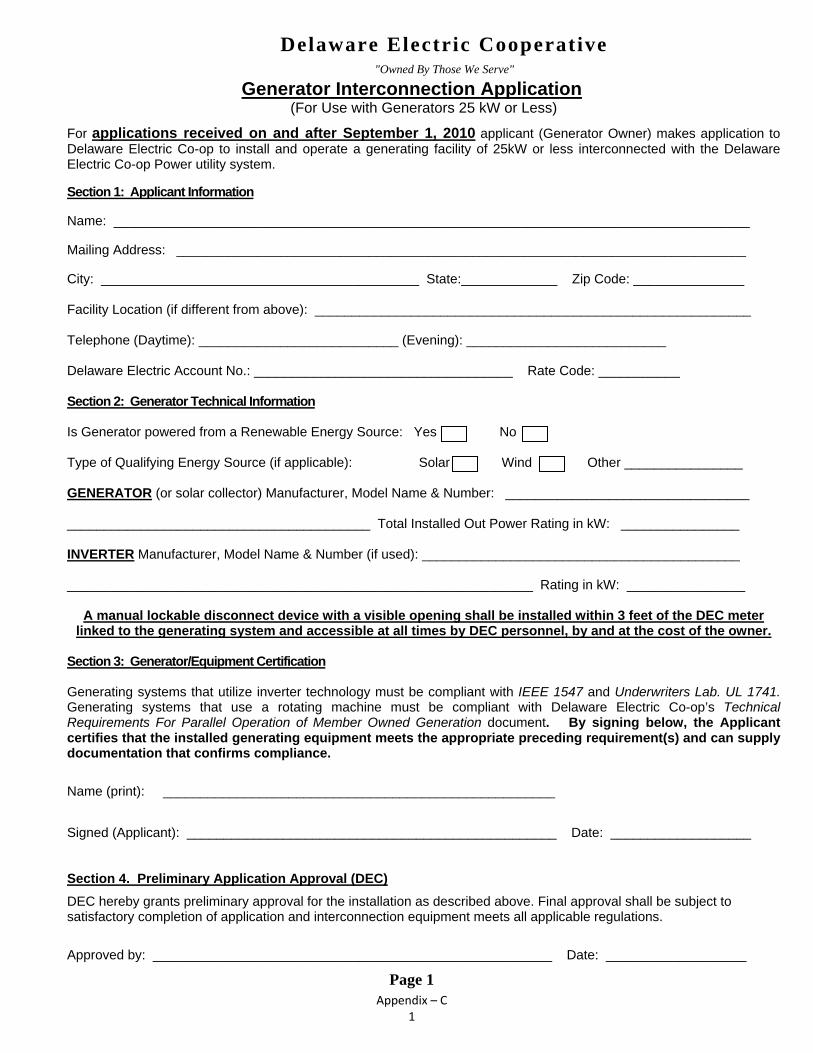
Appendix – C 1
Generator Interconnection Application (For Use with Generators 25 kW or Less)
For applications received on and after September 1, 2010 applicant (Generator Owner) makes application to Delaware Electric Co-op to install and operate a generating facility of 25kW or less interconnected with the Delaware Electric Co-op Power utility system.
Section 1: Applicant Information
Name: ______________________________________________________________________________________
Mailing Address: _____________________________________________________________________________
City: ___________________________________________ State:_____________ Zip Code: _______________
Facility Location (if different from above): ___________________________________________________________
Telephone (Daytime): ___________________________ (Evening): ___________________________
Delaware Electric Account No.: ___________________________________ Rate Code: ___________
Section 2: Generator Technical Information
Is Generator powered from a Renewable Energy Source: Yes No
Type of Qualifying Energy Source (if applicable): Solar Wind Other ________________
GENERATOR (or solar collector) Manufacturer, Model Name & Number: _________________________________ _________________________________________ Total Installed Out Power Rating in kW: ________________
INVERTER Manufacturer, Model Name & Number (if used): ___________________________________________
_______________________________________________________________ Rating in kW: ________________
A manual lockable disconnect device with a visible opening shall be installed within 3 feet of the DEC meter
linked to the generating system and accessible at all times by DEC personnel, by and at the cost of the owner.
Section 3: Generator/Equipment Certification
Generating systems that utilize inverter technology must be compliant with IEEE 1547 and Underwriters Lab. UL 1741. Generating systems that use a rotating machine must be compliant with Delaware Electric Co-op’s Technical Requirements For Parallel Operation of Member Owned Generation document. By signing below, the Applicant certifies that the installed generating equipment meets the appropriate preceding requirement(s) and can supply documentation that confirms compliance.
Name (print): _____________________________________________________
Signed (Applicant): __________________________________________________ Date: ___________________
Section 4. Preliminary Application Approval (DEC)
DEC hereby grants preliminary approval for the installation as described above. Final approval shall be subject to satisfactory completion of application and interconnection equipment meets all applicable regulations.
Approved by: ______________________________________________________ Date: ___________________
Page 1
Delaware Electric Cooperative "Owned By Those We Serve"
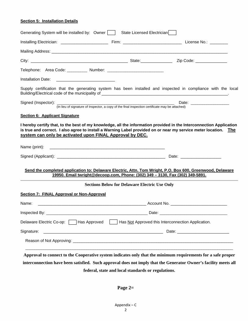
Appendix – C 2
Section 5: Installation Details
Generating System will be installed by: Owner State Licensed Electrician
Installing Electrician: _____________________ Firm: __________________________ License No.: ________
Mailing Address: ______________________________________________________________________________
City: ___________________________________________ State:______________ Zip Code: ______________
Telephone: Area Code: _________ Number: _________________________
Installation Date: __________________________
Supply certification that the generating system has been installed and inspected in compliance with the local Building/Electrical code of the municipality of ________________________________________________________.
Signed (Inspector): ____________________________________________________ Date: _________________
(In lieu of signature of Inspector, a copy of the final inspection certificate may be attached)
Section 6: Applicant Signature
I hereby certify that, to the best of my knowledge, all the information provided in the Interconnection Application is true and correct. I also agree to install a Warning Label provided on or near my service meter location. The system can only be activated upon FINAL Approval by DEC.
Name (print): ___________________________________________________ Signed (Applicant): ________________________________________________ Date: __________________
Send the completed application to: Delaware Electric, Attn. Tom Wright, P.O. Box 600, Greenwood, Delaware 19950. Email [email protected], Phone: (302) 349 – 3130, Fax (302) 349-5891.
Sections Below for Delaware Electric Use Only
Section 7: FINAL Approval or Non-Approval
Name: ________________________________________________ Account No. _________________________ Inspected By: _____________________________________________ Date: ______________________________ Delaware Electric Co-op: Has Approved Has Not Approved this Interconnection Application.
Signature: _____________________________________________________ Date: _______________________
Reason of Not Approving: _______________________________________________________________________
____________________________________________________________________________________________
Approval to connect to the Cooperative system indicates only that the minimum requirements for a safe proper
interconnection have been satisfied. Such approval does not imply that the Generator Owner’s facility meets all
federal, state and local standards or regulations.
Page 2=
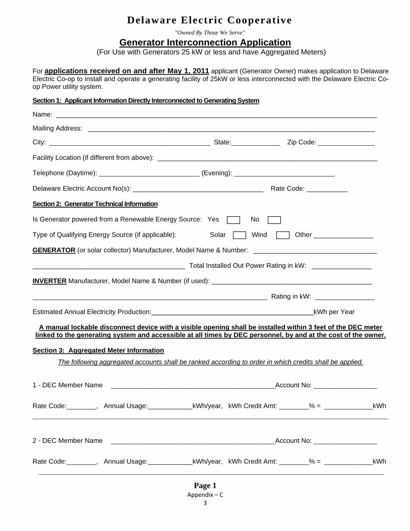
Appendix – C 3
Generator Interconnection Application (For Use with Generators 25 kW or less and have Aggregated Meters)
For applications received on and after May 1, 2011 applicant (Generator Owner) makes application to Delaware Electric Co-op to install and operate a generating facility of 25kW or less interconnected with the Delaware Electric Co-op Power utility system.
Section 1: Applicant Information Directly Interconnected to Generating System Name: ______________________________________________________________________________________ Mailing Address: _____________________________________________________________________________ City: ___________________________________________ State:_____________ Zip Code: _______________ Facility Location (if different from above): ___________________________________________________________ Telephone (Daytime): ___________________________ (Evening): ___________________________ Delaware Electric Account No(s): ___________________________________ Rate Code: ___________ Section 2: Generator Technical Information Is Generator powered from a Renewable Energy Source: Yes No Type of Qualifying Energy Source (if applicable): Solar Wind Other ________________ GENERATOR (or solar collector) Manufacturer, Model Name & Number: _________________________________ _________________________________________ Total Installed Out Power Rating in kW: ________________ INVERTER Manufacturer, Model Name & Number (if used): ___________________________________________ _______________________________________________________________ Rating in kW: ________________ Estimated Annual Electricity Production: kWh per Year
A manual lockable disconnect device with a visible opening shall be installed within 3 feet of the DEC meter
linked to the generating system and accessible at all times by DEC personnel, by and at the cost of the owner. Section 3: Aggregated Meter Information
The following aggregated accounts shall be ranked according to order in which credits shall be applied.
1 - DEC Member Name ____________________________________________Account No: _________________
Rate Code:________, Annual Usage: kWh/year, kWh Credit Amt: ________% = _____________kWh
2 - DEC Member Name ____________________________________________Account No: _________________
Rate Code:________, Annual Usage: kWh/year, kWh Credit Amt: ________% = _____________kWh
Page 1
Delaware Electric Cooperative "Owned By Those We Serve"

Appendix – C 4
3 - DEC Member Name ____________________________________________Account No: _________________
Rate Code:________, Annual Usage: kWh/year, kWh Credit Amt: ________% =
_____________kWh
4 - DEC Member Name ____________________________________________Account No: _________________
Rate Code:________, Annual Usage: kWh/year, kWh Credit Amt: ________% =
_____________kWh
5 - DEC Member Name ____________________________________________Account No: _________________
Rate Code:________, Annual Usage: kWh/year, kWh Credit Amt: ________% =
_____________kWh
6 - DEC Member Name ____________________________________________Account No: _________________
Rate Code:________, Annual Usage: kWh/year, kWh Credit Amt: ________% =
_____________kWh
Any additional meters associated with this aggregated system must be supplied on a separate sheet in the
same format.
Section 4: Generator/Equipment Certification
Generating systems that utilize inverter technology must be compliant with IEEE 1547 and Underwriters Lab. UL 1741. Generating systems that use a rotating machine must be compliant with Delaware Electric Co-op’s Technical Requirements For Parallel Operation of Member Owned Generation document. By signing below, the Applicant certifies that the installed generating equipment meets the appropriate preceding requirement(s) and can supply documentation that confirms compliance.
Name (print): _____________________________________________________
Signed (Applicant): __________________________________________________ Date: ___________________
Section 5: Preliminary Application Approval (DEC)
Prior to authorizing Preliminary Approval the Cooperative shall identify any upgrades or changes necessary to facilitate the interconnection and provide the applicant with a written cost estimate. The Applicant shall be responsible for paying any and all costs associated with interconnection prior to Preliminary Approval. DEC hereby grants preliminary approval for the installation as described above. Final approval shall be subject to satisfactory completion of application and interconnection equipment meets all applicable regulations. Approved by: ______________________________________________________ Date: ___________________
Page 2

Appendix – C 5
Section 6: Installation Details
Generating System will be installed by: Owner State Licensed Electrician
Installing Electrician: _____________________ Firm: __________________________ License No.: ________
Mailing Address: ______________________________________________________________________________
City: ___________________________________________ State:______________ Zip Code: ______________
Telephone: Area Code: _________ Number: _________________________
Installation Date: __________________________
Supply certification that the generating system has been installed and inspected in compliance with the local Building/Electrical code of the municipality of ________________________________________________________.
Signed (Inspector): ____________________________________________________ Date: _________________
(In lieu of signature of Inspector, a copy of the final inspection certificate may be attached)
Section 7: Applicant Signature
I hereby certify that, to the best of my knowledge, all the information provided in the Interconnection Application is true and correct. I also agree to install a Warning Label provided on or near my service meter location. The system can only be activated upon FINAL Approval by DEC.
Name (print): ___________________________________________________ Signed (Applicant): ________________________________________________ Date: __________________
Send the completed application to: Delaware Electric, Attn. Tom Wright, P.O. Box 600, Greenwood, Delaware 19950. Email [email protected], Phone: (302) 349 – 3130, Fax (302) 349-5891.
Sections Below for Delaware Electric Use Only
Section 8: FINAL Approval or Non-Approval
Name: ________________________________________________ Account No. _________________________ Inspected By: _____________________________________________ Date: ______________________________ Delaware Electric Co-op: Has Approved Has Not Approved this Interconnection Application.
Signature: _____________________________________________________ Date: _______________________
Reason of Not Approving: _______________________________________________________________________
____________________________________________________________________________________________
Approval to connect to the Cooperative system indicates only that the minimum requirements for a safe
proper interconnection have been satisfied. Such approval does not imply that the Generator Owner’s
facility meets all federal, state and local standards or regulations.
Page 3

Appendix D Generator Interconnection Application
For use with Generators Greater than 25kW

Appendix – D 1
Delaware Electric Cooperative Generator Interconnection Application –Long Form
(For Use with Generators Greater than 25 kW)
An applicant (Generator Owner) makes application to Delaware Electric Cooperative to install and operate a generating facility greater than 25kW interconnected with the Delaware Electric Cooperative utility system. Section 1, Applicant Information Name:_________________________________________________________________________________ Mailing Address:________________________________________________________________________ City:____________________________________State:__________________ZipCode:________________ Facility Location (if different from above): ___________________________________________________ Telephone (Daytime): Area Code _____ Number ___________ (Evening) Area Code____Number_______ Delaware Electric Cooperative Account No.:__________________________________________________ Rate Code:__________________________________________________ Section 2, Generator Type Is Generator powered from a Renewable Energy Source: Yes No Type of Energy Source (if applicable): Solar Wind Hydro Other generator energy source: Diesel, Natural Gas Diesel, Fuel Oil Other: ______________ Will excess power be exported to Delaware Electric Cooperative? Yes No
Site Load: __________________ kW (Typical) Maximum Export: ____________________ kW. Section 3, Generator Technical Information Type of Generator: Synchronous Induction DC Generator or Solar with Inverter Generator (or solar collector) Manufacturer, Model Name & Number: _____________________________ (A copy of Generator Nameplate and Manufacturer’s Specification Sheet may be substituted) ____________________________________________ Output Power Rating in kW:__________________ Inverter Manufacturer, Model Name & Number (if used): _______________________________________ (A copy of Inverter Nameplate and Manufacturer’s Specification Sheet may be substituted)
______________________________________________ Rating in kW: ____________________________ Generator Characteristic Data (for rotating machines): (Not needed if Generator Nameplate and Manufacture’s Specification Sheet is provided)
Direct Axis Synchronous Reactance, Xd: _______ P.U. Negative Sequence Reactance: _________ P.U.
Ddirect Axis Transient Reactance, X’d: _______ P.U. Zero Sequence Reactance: _________ P.U.
Direct Axis Subtransient Reactance, X”d: ______ P.U. KVA Base: __________________________
Page 1

Appendix – D 2
Delaware Electric Cooperative Generator Interconnection Application -Long Form
Section 4, Interconnecting Equipment Technical Data Will an interposing transformer be used between the generator and the point of interconnection?
Yes No Transformer Data (if applicable, for Customer Owned Transformer): (A copy of transformer Nameplate and Manufacturer’s Test Report may be substituted) Size: ______ KVA . Transformer Primary : ________ Volts Delta Wye Wye Grounded
Transformer Secondary: ________ Volts Delta Wye Wye Grounded Transformer Impedance: ______% on ______ KVA Base Transformer Fuse Data (if applicable, for Customer Owned Fuse): (Attach copy of fuse manufacturer’s Minimum Melt & Total Clearing Time-Current Curves)
Manufacturer: ________________ Type: _____________ Size: _______________ Speed: _____________ Interconnecting Circuit Breaker (if applicable): (A copy of breaker’s Nameplate and Specification Sheet may be substituted)
Manufacturer: _______ Type: _____ Load Rating: _____ Interrupting Rating: ______ Trip Speed: ______ (Amps) (Amps) (Cycles)
Circuit Breaker Protective Relays (if applicable): (Enclose copy of any proposed Time-Overcurrent Coordination Curves)
Manufacturer: ________ Type: _______ Style/Catalog No.: _______ Proposed Setting:________________
Manufacturer: ________ Type: _______ Style/Catalog No.: _______ Proposed Setting: _______________
Manufacturer: ________ Type: _______ Style/Catalog No.: _______ Proposed Setting:________________
Manufacturer: ________ Type: _______ Style/Catalog No.: _______ Proposed Setting:________________
Manufacturer: ________ Type: _______ Style/Catalog No.: _______ Proposed Setting:________________
Current Transformer Data (if applicable): (Enclose copy of Manufacturer’s Excitation & Ratio Correction Curves)
Manufacturer: ________ Type: _______ Accuracy Class: ________ Proposed Ratio Connection: ______/5
Manufacturer: ________ Type: _______ Accuracy Class: ________ Proposed Ratio Connection: ______/5 Generator Disconnect Switch: A lockable disconnect device shall be installed within 3 feet of the DEC meter and accessible at all times by DEC personnel, by and at the cost of the owner. Manufacturer: _______ Type: _______ Catalog No.: _______ Rated Volts: ______ Rated Amps:________ Single or 3 Phase: _______ Mounting Location: _______________________________________________
Page 2

Appendix – D 3
Delaware Electric Cooperative Generator Interconnection Application -Long Form
Section 5, General Technical Information Enclose copy of site One-Line Diagram showing configuration and interconnection of all equipment, current and potential circuits and protection and control schemes. Is One-Line Diagram Enclosed?: Yes Enclose copy of any site documentation that describes and details the operation of the protection and control schemes. Is Any Available Documentation Enclosed?: Yes Enclose copies of schematic drawings for all protection and control circuits, relay current circuits, relay potential circuits, and alarm/monitoring circuits. Are Schematic Drawings Enclosed?: Yes Section 6, PJM Interconnection Queue The Generator Owner must submit a Generation Interconnection Request directly to PJM if: any Generation is designated in whole or in part as a Capacity Resource to PJM or, if generator intends to sell output to another entity at another electrical location. Generation which is operating “behind the meter” in isolation from the PJM bulk power transmission system and which does not intend to participate in the PJM wholesale energy market may not need to apply to the PJM interconnection queue. PJM has sole discretion on interconnection queue requirements. Prior to installation send the completed Pages 1-3 to Delaware Electric Cooperative, Attn: Troy Dickerson, Manager of Engineering: Phone: (302) 349-3125 FAX: (302) 349-5891 Email: [email protected] or mail to P.O. Box 600 Greenwood, DE 19950 Section 7, Preliminary Approval to Proceed with Interconnection Delaware Electric Cooperative: Has Approved Has Not Approved this Preliminary Application. Name :____________________________________________________ Date: _______________________ Signature: _________________________________________________ Reason of Not Approving: ________________________________________________________________ __________________________________________________________________________________ __________________________________________________________________________________ __________________________________________________________________________________
Page 3

Appendix – D 4
Delaware Electric Cooperative Generator Interconnection Application -Long Form
Section 8, Installation Details Generating System will be installed by: Owner State Licensed Electrician Installing Electrician: _________________ Firm: ______________________ License No.: ____________ Mailing Address: _______________________________________________________________________ City: _________________________________ State:__________________ Zip Code: ________________ Telephone with Area Code: ___________________________________ Installation Date: __________________________ Interconnection Date: ___________________________ Supply certification that the generating system has been installed and inspected in compliance with the local Building/Electrical code of the municipality of ___________________________________________ Signed (Inspector): __________________________________________ Date:_______________________ (In lieu of signature of Inspector, a copy of the final inspection certificate may be attached) Section 9, Generator/Equipment Certification Generating systems that utilize inverter technology must be compliant with IEEE 1547 and Underwriters Lab. UL 1741. Generating systems must be compliant with Delaware Electric Cooperative’s “Technical Requirements for Parallel Operation of Member Owned Generation” document. The Applicant must certify that the installed generating equipment meets the appropriate preceding requirement(s) and can supply documentation that confirms compliance. Generation cannot be turned on until a Delaware Electric Cooperative representative has performed a site visit, installed a warning label near the service meter, and has authorized the system for interconnection. Section 10, Applicant Signature I hereby certify that, to the best of my knowledge, all the information provided in the Interconnection Application is true and correct. Signature of Applicant: _____________________________________ Date: ________________________
Page 4

Appendix – D 5
Delaware Electric Cooperative Generator Interconnection Application -Long Form
(For Use with Generators Greater than 25 kW)
This page for use by Delaware Electric Cooperative Only
Section 11, Approval or Non-Approval Delaware Electric Cooperative: Has Approved Has Not Approved this Interconnection Application. Name :____________________________________________________ Date: _______________________ Signature: _________________________________________________ Reason of Not Approving: ________________________________________________________________ __________________________________________________________________________________ __________________________________________________________________________________ __________________________________________________________________________________ __________________________________________________________________________________ Approval to connect to the Company system indicates only that the minimum requirements for a safe proper interconnection have been satisfied. Such approval does not imply that the Generator Owner’s facility meets all federal, state and local standards or regulations. Section 11, Internal Checks and Notifications DEC has performed a site visit and approved the system: Yes
DEC has installed a Warning Label on or near the service meter: Yes
Notify Billing Dept. of Interconnected Generation: Yes
Notify Mapping Dept. of Interconnected Generation: Yes
Notify Metering Dept. of Interconnected Generation: Yes
Notify System Protection of Interconnected Generation: Yes At completion send Pages 4 - 5 to Delaware Electric Cooperative, Attn: Troy Dickerson, Manager of Engineering: Phone: (302) 349-3125 FAX: (302) 349-5891 Email: [email protected] or mail to P.O. Box 600 Greenwood, DE 19950
Page 5

Appendix – D 6
Delaware Electric Cooperative Generator Interconnection Application –Long Form
(For Use with Generators Greater than 25 kW and have Aggregated Meters)
An applicant (Generator Owner) makes application to Delaware Electric Cooperative to install and operate a generating facility greater than 25kW interconnected with the Delaware Electric Cooperative utility system. Section 1, Applicant Information Directly Interconnected to the Generating System Name:_________________________________________________________________________________ Mailing Address:________________________________________________________________________ City:____________________________________State:__________________ZipCode:________________ Facility Location (if different from above): ___________________________________________________ Telephone (Daytime): Area Code _____ Number ___________ (Evening) Area Code____Number_______ Delaware Electric Cooperative Account No.:__________________________________________________ Rate Code:__________________________________________________ Section 2, Aggregated Meter Information The following aggregated accounts shall be ranked according to the order in which credits shall be applied 1 - DEC Member Name ____________________________________________Rate Code: _________________
DEC Account No.:____________________ kWh Credit Amt: _____________ Capacity (DEC):__________
2 - DEC Member Name ____________________________________________Rate Code: _________________
DEC Account No.:____________________ kWh Credit Amt: _____________ Capacity (DEC):__________
3 - DEC Member Name ____________________________________________Rate Code: _________________
DEC Account No.:____________________ kWh Credit Amt: _____________ Capacity (DEC):__________
4 - DEC Member Name ____________________________________________Rate Code: _________________
DEC Account No.:____________________ kWh Credit Amt: _____________ Capacity (DEC):__________
5 - DEC Member Name ____________________________________________Rate Code: _________________
DEC Account No.:____________________ kWh Credit Amt: _____________ Capacity (DEC):__________
Page 1

Appendix – D 7
Section 2, Aggregated Meter Information (continued)
6 - DEC Member Name ____________________________________________Rate Code: _________________
DEC Account No.:____________________ kWh Credit Amt: _____________ Capacity (DEC):__________
7 - DEC Member Name ____________________________________________Rate Code: _________________
DEC Account No.:____________________ kWh Credit Amt: _____________ Capacity (DEC):__________
8 - DEC Member Name ____________________________________________Rate Code: _________________
DEC Account No.:____________________ kWh Credit Amt: _____________ Capacity (DEC):__________
Any additional meters associated with this aggregated system must be supplied on a separate sheet in the same format.
Section 3, Generator Type Is Generator powered from a Renewable Energy Source: Yes No Type of Energy Source (if applicable): Solar Wind Hydro Other generator energy source: Diesel, Natural Gas Diesel, Fuel Oil Other: ______________ Will excess power be exported to Delaware Electric Cooperative? Yes No
Total Aggregated Maximum Load: ________________ kW (Typical) Maximum Export: ____________________ kW Section 4, Generator Technical Information Type of Generator: Synchronous Induction DC Generator or Solar with Inverter Generator (or solar collector) Manufacturer, Model Name & Number: _____________________________ (A copy of Generator Nameplate and Manufacturer’s Specification Sheet may be substituted) ____________________________________________ Output Power Rating in kW:__________________ Inverter Manufacturer, Model Name & Number (if used): _______________________________________ (A copy of Inverter Nameplate and Manufacturer’s Specification Sheet may be substituted)
______________________________________________ Rating in kW: ____________________________ Generator Characteristic Data (for rotating machines): (Not needed if Generator Nameplate and Manufacture’s Specification Sheet is provided)
Direct Axis Synchronous Reactance, Xd: _______ P.U. Negative Sequence Reactance: _________ P.U.
Ddirect Axis Transient Reactance, X’d: _______ P.U. Zero Sequence Reactance: _________ P.U.
Direct Axis Subtransient Reactance, X”d: ______ P.U. KVA Base: __________________________
Page 2

Appendix – D 8
Delaware Electric Cooperative Generator Interconnection Application -Long Form
Section 5, Interconnecting Equipment Technical Data Will an interposing transformer be used between the generator and the point of interconnection?
Yes No Transformer Data (if applicable, for Customer Owned Transformer): (A copy of transformer Nameplate and Manufacturer’s Test Report may be substituted) Size: ______ KVA . Transformer Primary : ________ Volts Delta Wye Wye Grounded
Transformer Secondary: ________ Volts Delta Wye Wye Grounded Transformer Impedance: ______% on ______ KVA Base Transformer Fuse Data (if applicable, for Customer Owned Fuse): (Attach copy of fuse manufacturer’s Minimum Melt & Total Clearing Time-Current Curves)
Manufacturer: ________________ Type: _____________ Size: _______________ Speed: _____________ Interconnecting Circuit Breaker (if applicable): (A copy of breaker’s Nameplate and Specification Sheet may be substituted)
Manufacturer: _______ Type: _____ Load Rating: _____ Interrupting Rating: ______ Trip Speed: ______ (Amps) (Amps) (Cycles)
Circuit Breaker Protective Relays (if applicable): (Enclose copy of any proposed Time-Overcurrent Coordination Curves)
Manufacturer: ________ Type: _______ Style/Catalog No.: _______ Proposed Setting:________________
Manufacturer: ________ Type: _______ Style/Catalog No.: _______ Proposed Setting: _______________
Manufacturer: ________ Type: _______ Style/Catalog No.: _______ Proposed Setting:________________
Manufacturer: ________ Type: _______ Style/Catalog No.: _______ Proposed Setting:________________
Manufacturer: ________ Type: _______ Style/Catalog No.: _______ Proposed Setting:________________
Current Transformer Data (if applicable): (Enclose copy of Manufacturer’s Excitation & Ratio Correction Curves)
Manufacturer: ________ Type: _______ Accuracy Class: ________ Proposed Ratio Connection: ______/5
Manufacturer: ________ Type: _______ Accuracy Class: ________ Proposed Ratio Connection: ______/5 Generator Disconnect Switch: A lockable disconnect device shall be installed within 3 feet of the DEC meter and accessible at all times by DEC personnel, by and at the cost of the owner. Manufacturer: _______ Type: _______ Catalog No.: _______ Rated Volts: ______ Rated Amps:________ Single or 3 Phase: _______ Mounting Location: _______________________________________________
Page 3
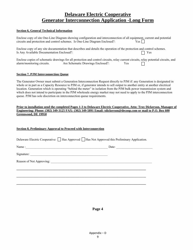
Appendix – D 9
Delaware Electric Cooperative Generator Interconnection Application -Long Form
Section 6, General Technical Information Enclose copy of site One-Line Diagram showing configuration and interconnection of all equipment, current and potential circuits and protection and control schemes. Is One-Line Diagram Enclosed?: Yes Enclose copy of any site documentation that describes and details the operation of the protection and control schemes. Is Any Available Documentation Enclosed?: Yes Enclose copies of schematic drawings for all protection and control circuits, relay current circuits, relay potential circuits, and alarm/monitoring circuits. Are Schematic Drawings Enclosed?: Yes Section 7, PJM Interconnection Queue The Generator Owner must submit a Generation Interconnection Request directly to PJM if: any Generation is designated in whole or in part as a Capacity Resource to PJM or, if generator intends to sell output to another entity at another electrical location. Generation which is operating “behind the meter” in isolation from the PJM bulk power transmission system and which does not intend to participate in the PJM wholesale energy market may not need to apply to the PJM interconnection queue. PJM has sole discretion on interconnection queue requirements. Prior to installation send the completed Pages 1-3 to Delaware Electric Cooperative, Attn: Troy Dickerson, Manager of Engineering: Phone: (302) 349-3125 FAX: (302) 349-5891 Email: [email protected] or mail to P.O. Box 600 Greenwood, DE 19950 Section 8, Preliminary Approval to Proceed with Interconnection Delaware Electric Cooperative: Has Approved Has Not Approved this Preliminary Application. Name :____________________________________________________ Date: _______________________ Signature: _________________________________________________ Reason of Not Approving: ________________________________________________________________ __________________________________________________________________________________ __________________________________________________________________________________ __________________________________________________________________________________
Page 4
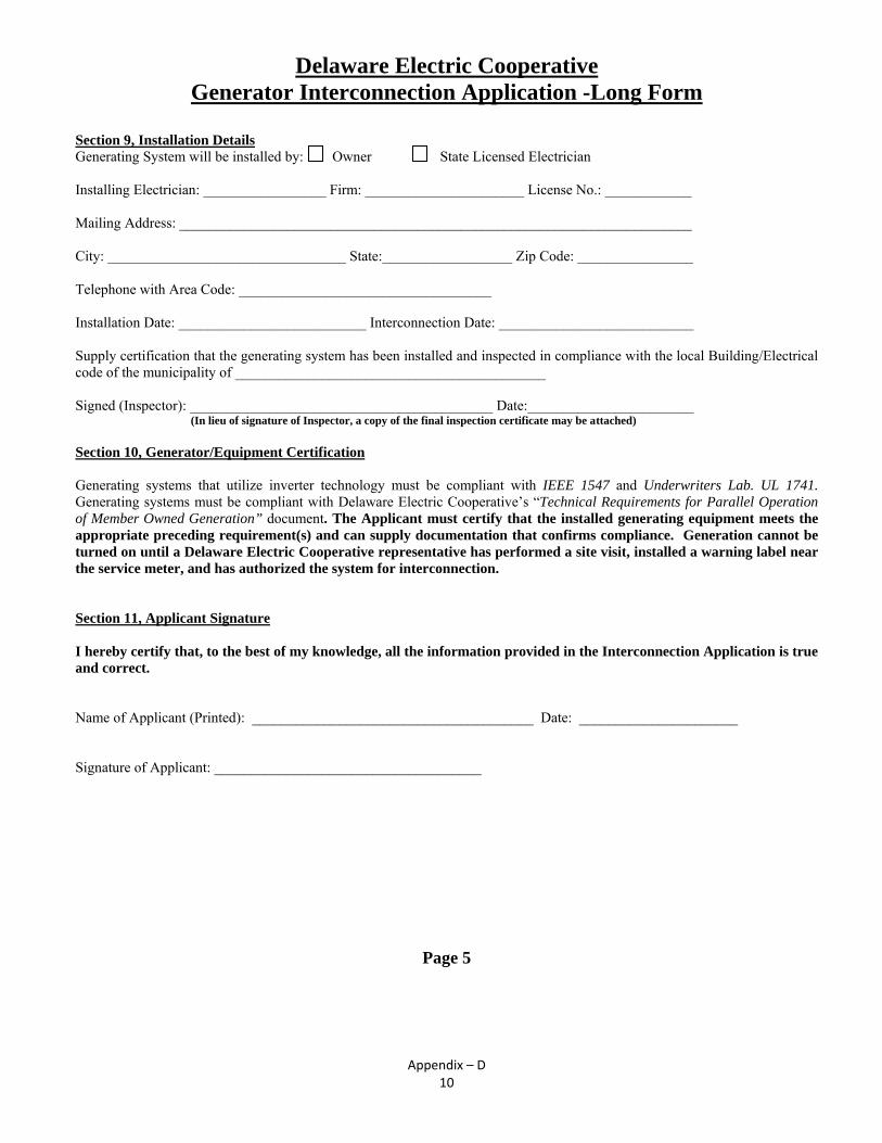
Appendix – D 10
Delaware Electric Cooperative Generator Interconnection Application -Long Form
Section 9, Installation Details Generating System will be installed by: Owner State Licensed Electrician Installing Electrician: _________________ Firm: ______________________ License No.: ____________ Mailing Address: _______________________________________________________________________ City: _________________________________ State:__________________ Zip Code: ________________ Telephone with Area Code: ___________________________________ Installation Date: __________________________ Interconnection Date: ___________________________ Supply certification that the generating system has been installed and inspected in compliance with the local Building/Electrical code of the municipality of ___________________________________________ Signed (Inspector): __________________________________________ Date:_______________________ (In lieu of signature of Inspector, a copy of the final inspection certificate may be attached) Section 10, Generator/Equipment Certification Generating systems that utilize inverter technology must be compliant with IEEE 1547 and Underwriters Lab. UL 1741. Generating systems must be compliant with Delaware Electric Cooperative’s “Technical Requirements for Parallel Operation of Member Owned Generation” document. The Applicant must certify that the installed generating equipment meets the appropriate preceding requirement(s) and can supply documentation that confirms compliance. Generation cannot be turned on until a Delaware Electric Cooperative representative has performed a site visit, installed a warning label near the service meter, and has authorized the system for interconnection. Section 11, Applicant Signature I hereby certify that, to the best of my knowledge, all the information provided in the Interconnection Application is true and correct. Name of Applicant (Printed): _______________________________________ Date: ______________________ Signature of Applicant: _____________________________________
Page 5

Appendix – D 11
Delaware Electric Cooperative Generator Interconnection Application -Long Form
(For Use with Generators Greater than 25 kW)
This page for use by Delaware Electric Cooperative Only
Section 12, Approval or Non-Approval Delaware Electric Cooperative: Has Approved Has Not Approved this Interconnection Application. Name :____________________________________________________ Date: _______________________ Signature: _________________________________________________ Reason of Not Approving: ________________________________________________________________ __________________________________________________________________________________ __________________________________________________________________________________ __________________________________________________________________________________ __________________________________________________________________________________ Approval to connect to the Company system indicates only that the minimum requirements for a safe proper interconnection have been satisfied. Such approval does not imply that the Generator Owner’s facility meets all federal, state and local standards or regulations. Section 13, Internal Checks and Notifications DEC has performed a site visit and approved the system: Yes
DEC has installed a Warning Label on or near the service meter: Yes
Notify Billing Dept. of Interconnected Generation: Yes
Notify Mapping Dept. of Interconnected Generation: Yes
Notify Metering Dept. of Interconnected Generation: Yes
Notify System Protection of Interconnected Generation: Yes At completion send Pages 5 - 6 to Delaware Electric Cooperative, Attn: Troy Dickerson, Manager of Engineering: Phone: (302) 349-3125 FAX: (302) 349-5891 Email: [email protected] or mail to P.O. Box 600 Greenwood, DE 19950
Page 6

Appendix E Typical Basic One Line Diagrams

Appendix – E 1

Appendix – E 2

Appendix – E 3

Appendix – E 4

Appendix – E 5
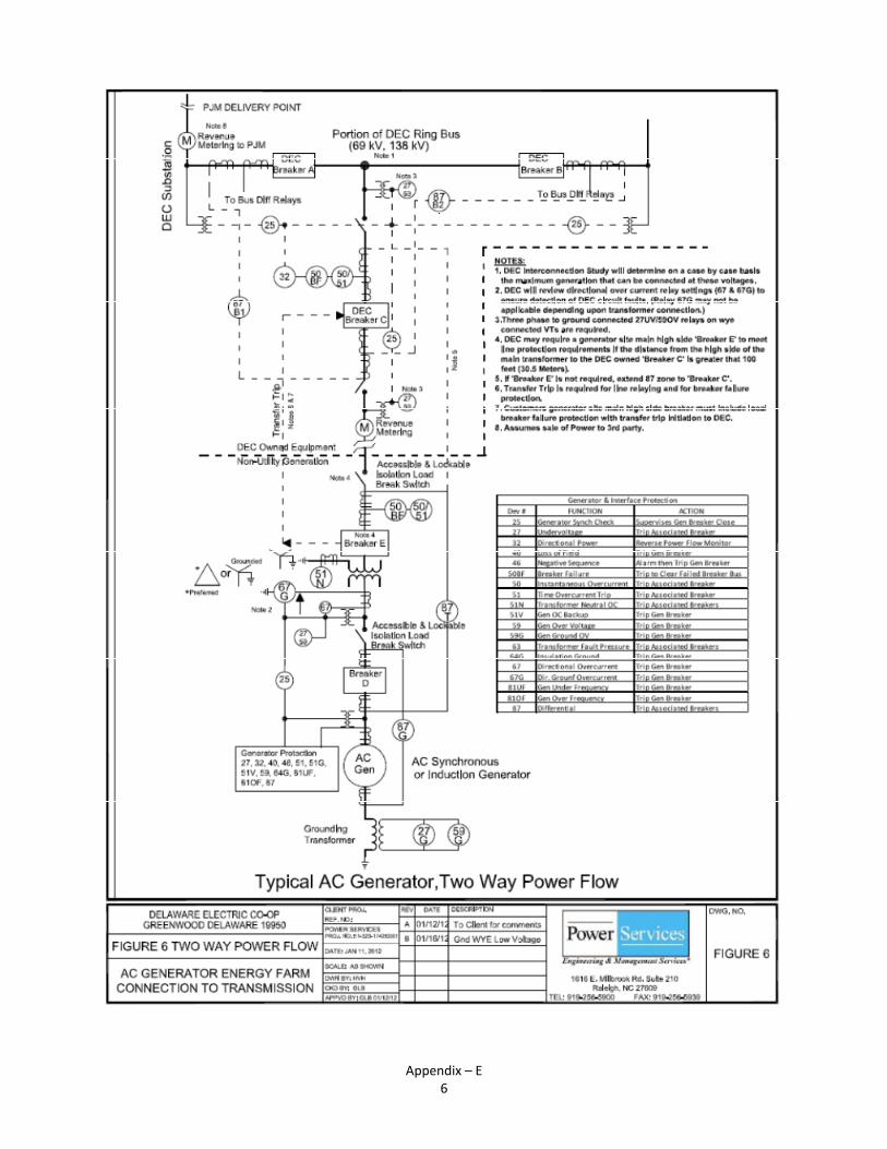
Appendix – E 6