Embed Size (px)
Citation preview
URBAN DRAINAGE AND FLOOD CONTROL DISTRICT
TECHNICAL REVIEW GUIDELINES
FOR
GRAVEL MINING & WATER STORAGE ACTIVITIES
Within or Adjacent to 100-Year Floodplains
Prepared in Cooperation with Adams County
Project Consultant Wright Water Engineers, Inc.
January 2013
January 2013 Urban Drainage and Flood Control District Page i
TABLE OF CONTENTS
1.0 INTRODUCTION ............................................................................................................. 1 1.1 Title ..................................................................................................................................... 1 1.2 Jurisdiction .......................................................................................................................... 1 1.3 Purpose ............................................................................................................................... 1 1.4 Enactment Authority ........................................................................................................... 2 1.5 Definition Of Terms And Abbreviations .............................................................................. 2
1.5.1 Definitions ......................................................................................................... 2 1.5.2 Abbreviations .................................................................................................... 4
2.0 OFF-RIVER GRAVEL MINING AND WATER STORAGE RESERVOIRS ...................... 6 2.1 Types of River Alignment .................................................................................................... 6
2.1.1 Existing Unstable Alignment ......................................................................... 6 2.1.2 Master Plan Alignment ...................................................................................... 6 2.1.3 Minimum Maintenance Alignment..................................................................... 7
2.2 Revegetation of Berms ..................................................................................................... 10 2.2.1 Revegetation of River Banks .......................................................................... 10 2.2.2 Revegetation of Pitside Banks and Top of Berm ............................................ 10 2.2.3 Revegetation of Soil Riprap Areas ................................................................. 10
2.3 Riverbank Protection ......................................................................................................... 11 2.3.1 Riprap ............................................................................................................. 11 2.3.2 Soil Riprap ...................................................................................................... 11 2.3.3 Jetties (Groins)................................................................................................ 12
2.4 Pitside Bank Protection ..................................................................................................... 15 2.4.1 Riprap ............................................................................................................. 15 2.4.2 Soil Riprap ...................................................................................................... 16 2.4.3 Soil Cement .................................................................................................... 16 2.4.4 Grouted Boulders ............................................................................................ 17 2.4.5 Side Channel Spillway .................................................................................... 17
2.5 Lateral Berms .................................................................................................................... 22 2.5.1 Type A Lateral Berms ..................................................................................... 22 2.5.2 Type B Lateral Berms ..................................................................................... 22 2.5.3 Protection of Lateral Berms ............................................................................ 22 2.5.4 Spillway for Type A Lateral Berms.................................................................. 23
2.6 Berm-Top Width—Riverbank Berms ................................................................................. 23 2.6.1 Existing Unstable Alignment ........................................................................... 24 2.6.2 Master Plan Alignment and Minimum Maintenance Alignment ...................... 24
2.7 Berm-Top Width—Lateral Berms ...................................................................................... 25 2.7.1 Type A Lateral Berms ..................................................................................... 25 2.7.2 Type B Lateral Berms ..................................................................................... 25
2.8 Berm-Top Widths .............................................................................................................. 26
3.0 IN-RIVER GRAVEL MINING ......................................................................................... 29 3.1 Groundwater Impacts ........................................................................................................ 29 3.2 Sediment Transport........................................................................................................... 29 3.3 Water Quality .................................................................................................................... 30 3.4 Side Slope Protection........................................................................................................ 30 3.5 Headcutting Control .......................................................................................................... 30
3.5.1 Control Structures ........................................................................................... 30 3.5.2 Location of Control Structures ........................................................................ 30 3.5.3 Overbank Protection ....................................................................................... 31
3.6 Upstream Protection ......................................................................................................... 31 3.6.1 Extent of Upstream Protection ........................................................................ 31 3.6.2 Type of Protection ........................................................................................... 31
January 2013 Urban Drainage and Flood Control District Page ii
4.0 RECLAMATION ............................................................................................................ 33 4.1 Recreational Criteria ......................................................................................................... 33 4.2 Revegetation Criteria ........................................................................................................ 33
5.0 WATER STORAGE RESERVOIRS .............................................................................. 35
TABLES
Table 2.1 Riverbank Berm Top Width ............................................................................................... 27 Table 2.2 Lateral Berm Top Width .................................................................................................... 28
FIGURES
Figure 2.1 Typical Minimum Maintenance Alignment .......................................................................... 9 Figure 2.2 Typical Riprap Slope Protection ........................................................................................ 13 Figure 2.3 Typical Soil Riprap Slope Protection................................................................................. 13 Figure 2.4 Jetty Slope Protection ....................................................................................................... 14 Figure 2.5 Typical Riprap Slope Protection (Pitside Slope) ............................................................... 19 Figure 2.6 Typical Soil Cement Slope Protection (Pitside Slope) ...................................................... 19 Figure 2.7 Typical Grouted Boulder Slope Protection (Pitside Slope) ............................................... 20 Figure 2.8 Riprap Spillway Stabilization ............................................................................................. 20 Figure 2.9 Concrete Spillway Stabilization ......................................................................................... 21 Figure 2.10 Soil Cement Spillway Stabilization .................................................................................... 21 Figure 3.1 Typical Instream Headcutting Control Structure ............................................................... 32
January 2013 Urban Drainage and Flood Control District Page 1
TECHNICAL REVIEW GUIDELINES FOR GRAVEL MINING & WATER STORAGE ACTIVITIES
1.0 INTRODUCTION
1.1 Title
These technical review guidelines together with all future amendments shall be known as “Technical Review Guidelines for Gravel Mining and Water Storage Activities Within or Adjacent to 100-year Floodplains” (hereafter called “Guidelines”).
1.2 Jurisdiction
These Guidelines shall apply to all proposed gravel mining operations, water storage reservoirs or any other excavation below the normal water level of the 100-year floodplain, or within 500 feet of the low flow channel if outside the 100-year floodplain of the South Platte River and its tributaries within Urban Drainage & Flood Control District (hereinafter called “District”).
1.3 Purpose
Presented in these Guidelines are the minimum requirements for gravel mining operations and water storage reservoirs located in or adjacent to 100-year floodplains within the District. It is the intent of these Guidelines to help protect the general public and property owners adjacent to rivers and streams from unreasonable hazard resulting from river or stream instabilities. These Guidelines were originally designed to protect the South Platte River and related properties and infrastructure from adverse impacts resulting from the extraction of gravel in or near the river by providing guidelines for maintaining river stability and protecting overbank areas from both routine and catastrophic failure. The Guidelines were also used for planning and design criteria for conversion of gravel pits to water storage reservoirs. As a result, these Guidelines are directly applicable to land shaping operations along the South Platte River. However, they also provide guidance for operations along South Platte River tributaries, but may require modifications on a case-by-case basis to recognize differences in geology, hydrology and site conditions. These Guidelines are also intended to provide a consistent basis for District review and action in matters dealing with gravel mining and water storage reservoirs within or adjacent to 100-year floodplains.
Existing and future sand and gravel mining, mine reclamation and development of water supply storage facilities are ongoing in the Planning Area and will continue to occur in the future. To minimize the impacts of these activities on the river channel stability, floodplain and habitat, it is extremely important that floodplain regulation and mine reclamation permitting processes take the possible effects of such activities fully into account when issuing permits. The actual post-
Technical Review Guidelines for Gravel Mining & Water Storage Activities
January 2013 Urban Drainage and Flood Control District Page 2
development flood storage, river stability and conveyance characteristics cannot be allowed to be diminished over time. It is also extremely important that the berms between the river and all active and/or reclaimed gravel mines be protected from erosion and breakthrough when they are overtopped in order to limit upstream headcutting and associated damages to public and private properties and infrastructure that can result.
During the approval process of mining permits, consideration should also be given to allowing for multiple post-mining uses in cases where the pits are to provide a minimum conservation pool when used for purposes of water supply augmentation. In this way, the resulting pond/lake can serve both their intended purpose as well as provide habitat for river corridor wildlife and potentially some level of access to the public.
1.4 Enactment Authority
These Guidelines are adopted by the Urban Drainage & Flood Control District’s Board of Directors as the District’s review guidelines. These Guidelines are not intended to supersede the Rules and Regulations for Mining Operations in the State of Colorado as adopted by the Colorado Mined Land Reclamation Board (34-32-108, CRS) but rather to supplement them. All referrals by general purpose governments and special districts within the District will be reviewed using these Guidelines as the basis for comment and, if necessary, action before the Colorado Mined Land Reclamation Board where existing or proposed mining activities threaten the long-term stability of the South Platte River.
1.5 Definition Of Terms And Abbreviations
1.5.1 Definitions
As used in these Guidelines, the following definitions shall apply:
Adjacent Within 400 feet when used in reference to the South Platte River. The 400- foot distance shall be measured from the top of the river bank to the top of the gravel pit bank or from the Master Plan alignment boundary to the top of the gravel pit bank, whichever is greater.
Berms Areas of native material or fill material separating a river or stream from the overbank gravel pit or separating one overbank gravel pit from another overbank gravel pit.
County A county totally or partially within District's boundaries. District Urban Drainage & Flood Control District (UDFCD). FEMA Federal Emergency Management Agency. FHAD A Flood Hazard Area Delineation report prepared by District. Floodplain Land adjacent to a watercourse which is subject to flooding as a result of the
occurrence of the 100-year or 1 percent frequency flood of a watercourse. Flood Profile A graph or a longitudinal profile showing the relationship of the water surface
elevation of a flood event to a location along a stream or river.
Technical Review Guidelines for Gravel Mining & Water Storage Activities
January 2013 Urban Drainage and Flood Control District Page 3
Floodway That area of the floodplain required for a reasonable passage or conveyance of the 100-year flood and which will convey the flood flows with not more than 0.5 foot rise in the water surface elevation based on the assumption that there will be an equal degree of encroachment onto the overbank conveyances on both sides of the floodplain.
Guidelines These Technical Review Guidelines for Gravel Mining Activities within or adjacent to 100-year Floodplains.
Guidelines for Vegetation
UDFCD, Urban Storm Drainage Criteria Manual, Volume 2, 2008, Revegetation chapter.
High Water Line The elevation used to determine the volume of overbank gravel pits. The high water line elevation shall be the spillway elevation when only one spillway is used or the average of both spillways when two are used.
Hydraulic Radius The area of flow divided by the length of the section exposed to water. Instream Mining Mines located in the channel of the South Platte River or any of its tributaries, or
gravel mines which were originally cut off the channel if it is proposed to relocate the river or stream through those gravel mines in the future.
Interior Banks Banks which face the interior portion of gravel pits. Invert of the lowest point in the river or stream channel.
Jetties (Groins) Bank stabilization technique involving the placement of strips of stabilized fill projecting into the river channel from the banks.
Lateral Berms Berms constructed or left in place between pits, which are perpendicular to the general direction of flow of a river or a stream.
Local Government
Any general purpose government or a special district totally or partially within District boundaries.
Low Flow Channel
That portion of the channel which is subjected to continuous flow or frequent flows and where the flows are concentrated.
Master Plan The South Platte River Major Drainageway Planning from Chatfield Dam to Baseline Road, Phase B Report, June 1985 by Wright Water Engineers, Major Drainageway Planning South Platte River in Adams County, Colorado, Phase B Report, April 2002 by Camp Dresser & McKee Inc. or any other major drainageway plan prepared by the District.
Operators Any person, firm, partnership, association, corporation, or any department, division or agency of federal, state, county or municipal government engaged in or controlling a mining operation or a former mining operation.
Pitside Banks The interior bank of a gravel pit located adjacent to a river or a stream. Reach A hydraulic engineering term used to describe longitudinal segments of a stream or
river. Riprap Broken stone or boulders placed compactly or irregularly on earth or gravel surfaces
to protect against the erosive action of water. Riverside Berms Berms immediately adjacent to a river or a stream (see berms). Safety Factor The ratio of forces resisting movement to those attempting to initiate movement
(abbreviated SF). Setback The distance between any property line and the wall or support of structure. Setbacks
are not applicable to fences except where specifically indicated. Soil Riprap A uniform mixture of native soil or topsoil and riprap without voids and meeting the
UDFCD soil riprap specifications. Thalweg The lowest portion of a river or a stream channel. Urban Storm The latest version of the Criteria of the Urban Drainage and Flood Control District.
Technical Review Guidelines for Gravel Mining & Water Storage Activities
January 2013 Urban Drainage and Flood Control District Page 4
Drainage Criteria Manual
(Abbreviated USDCM).
Water Storage Activities
Conversion of gravel pits to water storage reservoirs for beneficial water supply purposes, or the constructions of new facilities within or adjacent to the 100-year floodplain.
1.5.2 Abbreviations
As used in these Guidelines, the following abbreviations shall apply:
Ap Area of gravel pit at the high water line, in square feet
B Bottom width of channel, in feet
D50 Median riprap particle size, in feet
H Height between top of berm and spillway crest
INV River or stream invert (i.e., thalweg)
L Length of the channel crossing between two curves, in feet
LH Horizontal spacing between jetties, in feet
Lm Meander length of two consecutive bends and crossings, in feet
Ls Length of side channel spillway crest, in feet
Ls1 Length of lateral berm spillway, in feet
Min Minimum
n Stability Factor
NWL Normal water level
R Hydraulic radius at normal depth of flow down pitside slope, in feet
RH Horizontal radius of the channel centerline, in feet
S Face slope of pitside bank, in feet per foot
SF Safety factor
SPR South Platte River
Ss Specific gravity of riprap particles
USDCM Urban Storm Drainage Criteria Manual
W.S. Water Surface
γ Specific weight of water (equal to 62.4 lbs/ft3)
∆ Deflection angle of the horizontal curve, in degrees
θ Face slope of pitside bank, in degrees
Technical Review Guidelines for Gravel Mining & Water Storage Activities
January 2013 Urban Drainage and Flood Control District Page 5
τs Tractive force, in lbs/ft2
φ Angle of repose of pitside bank construction materials, in degrees
Technical Review Guidelines for Gravel Mining & Water Storage Activities
January 2013 Urban Drainage and Flood Control District Page 6
2.0 OFF-RIVER GRAVEL MINING AND WATER STORAGE RESERVOIRS
2.1 Types of River Alignment
The alignment of a river or stream channel is related to its geomorphology. The alignment affects the stability of the channel. This is true for the South Platte River and its many tributaries.
This section of the Guidelines describes three alignment classifications that are specific to the South Platte River for which the policies and principles apply to the tributaries.
The original 1985 Master Plan by Wright Water Engineers for Adams County was superseded by the April 2002 Mater Plan by CDM entitled Major Drainageway Planning South Platte River in Adams County, Colorado. The 2002 Master Plan alignment for Adams County includes both stable and unstable alignments. The use of “master plan” alignments in this Guideline refers only to stable channel portions of the 2002 Master Plan.
2.1.1 Existing Unstable Alignment
The alignment of portions of the South Platte River through Adams County in 1985 was considered unstable. Studies of aerial photos taken since 1937 show the river shifting its main channel horizontally, sometimes as much as 1,700 feet. On the other hand, by 2012, river berms for gravel mining and water storage reservoirs have confined large segments of the river to a defined and constrained corridor. The river’s thalweg also tends to be lower due to degradation. As the river exists today, portions of the river channel are considered unstable and capable of lateral and vertical movement.
As a minimum, if the gravel mining or water storage reservoir operator elects to preserve the river in its current unstable alignment, the river banks shall be regraded to have a 3 horizontal to 1 vertical (3H:1V) side slope and then revegetated per section 2.2 of these Guidelines. Sufficient river channel width must be provided to convey the 100-year flood to 88th Avenue and the 10-year flood downstream of 88th Avenue as described in the Master Plan.
2.1.2 Master Plan Alignment
The alignment shown in the CDM Master Plan for the Urban Drainage & Flood Control District in 2002 is a special case. It is a combination of existing alignment, a minimum maintenance alignment and more heavily protected channel that in some reaches differs from the minimum maintenance alignment requirements. The 2002 Master Plan alignment was developed in order to satisfy many constraints including: (1) the minimum maintenance alignment requirements, (2) property boundaries, (3) location of the existing river and (4) proposed improvements by the County, water storage reservoir operators and gravel operators. The Master Plan defines much of the horizontal alignment of the channel, the required invert profile of the channel in its ultimate
Technical Review Guidelines for Gravel Mining & Water Storage Activities
January 2013 Urban Drainage and Flood Control District Page 7
configuration and methods of bank protection proposed along the entire river. This alignment can be modified if it is technically demonstrated that the change is consistent with the intent of the Master Plan as approved by the District.
2.1.3 Minimum Maintenance Alignment
This alignment is intended to be used only when the operator can demonstrate that a change will benefit the river and still comply with the intent of the Master Plan alignment.
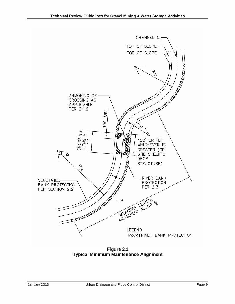
Studies by the District have resulted in an alternative recommended river alignment that may require significantly less maintenance to retain the river’s lateral stability. The configuration of the channel cross-section and geometric properties of the “minimum maintenance alignment” channel should be in accordance with the USDCM Open Channel/Hydraulic design parameters and in general conformance with Figure 2.1 with the following characteristics:
RH = 400 to 1,500 feet
∆ = R/60 + 50°
B = 250 feet
L = 300 to 700 feet
Lm/B = 7 to 15
In which,
RH = horizontal radius of the channel centerline, in feet
∆ = deflection angle of the horizontal curve in degrees (a tolerance of ±10° is acceptable)
B = bottom width of the channel, in feet
L = length of the channel crossing between two curves, in feet
Lm = meander length of two consecutive bends and crossings, in feet
The banks of the minimum maintenance alignment channel should be sloped back at a ratio of no less than 4H:1V except where soil riprap is used. In the riprap sections, the banks will be no steeper than 2.5H:1V. Soil riprap shall be used to protect the banks on the outside of bends and shall be continued into the downstream crossing for a distance of 450 feet as shown on Figure 2.1.
Vegetation only may be used in areas where, due to hydraulic conditions, riprap is not required. The evaluation for determining if riprap is required is based upon the Master Plan and USDCM Major Drainage chapter. In the portions of channel not requiring riprap bank protection as specified above, vegetation by itself may be used to protect banks above the 2-year flood. Below the 2-year flood level, riprap or soil riprap shall be used.
Technical Review Guidelines for Gravel Mining & Water Storage Activities
January 2013 Urban Drainage and Flood Control District Page 8
An armor layer would be provided at each crossing between channel bends. The armoring layer shall be no less than 18 inches thick to protect the river profile from degrading and shall consist of Type L or larger riprap as defined in the USDCM, or a gradation of cobble equivalent to Type L riprap. A grouted boulder drop structure of a shorter length could be used in lieu of armoring.
Where the minimum maintenance alignment channel is designed to control the 10-year flood, the berms will be designed to withstand the 100-year flood without failure during overtopping. If a 100-year berm is requested by the Adams County (or local government) Engineer, then the higher standard shall supersede the recommended standard, and all design shall conform accordingly. If the operator chooses to elevate the unprotected riverside berm above the 10-year level, the berm shall be protected in a manner consistent with the protection requirements for a minimum maintenance channel alignment for the entire height of the berm.
Technical Review Guidelines for Gravel Mining & Water Storage Activities
January 2013 Urban Drainage and Flood Control District Page 9
Figure 2.1 Typical Minimum Maintenance Alignment
Technical Review Guidelines for Gravel Mining & Water Storage Activities
January 2013 Urban Drainage and Flood Control District Page 10
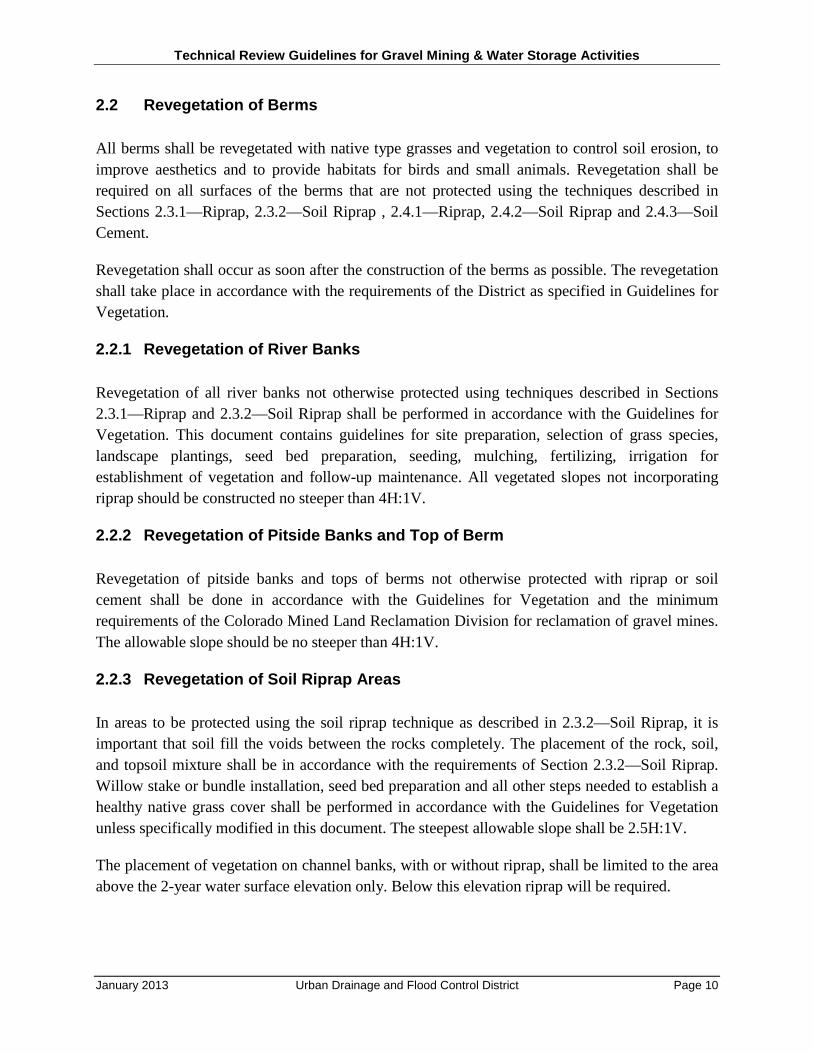
2.2 Revegetation of Berms
All berms shall be revegetated with native type grasses and vegetation to control soil erosion, to improve aesthetics and to provide habitats for birds and small animals. Revegetation shall be required on all surfaces of the berms that are not protected using the techniques described in Sections 2.3.1—Riprap, 2.3.2—Soil Riprap , 2.4.1—Riprap, 2.4.2—Soil Riprap and 2.4.3—Soil Cement.
Revegetation shall occur as soon after the construction of the berms as possible. The revegetation shall take place in accordance with the requirements of the District as specified in Guidelines for Vegetation.
2.2.1 Revegetation of River Banks
Revegetation of all river banks not otherwise protected using techniques described in Sections 2.3.1—Riprap and 2.3.2—Soil Riprap shall be performed in accordance with the Guidelines for Vegetation. This document contains guidelines for site preparation, selection of grass species, landscape plantings, seed bed preparation, seeding, mulching, fertilizing, irrigation for establishment of vegetation and follow-up maintenance. All vegetated slopes not incorporating riprap should be constructed no steeper than 4H:1V.
2.2.2 Revegetation of Pitside Banks and Top of Berm
Revegetation of pitside banks and tops of berms not otherwise protected with riprap or soil cement shall be done in accordance with the Guidelines for Vegetation and the minimum requirements of the Colorado Mined Land Reclamation Division for reclamation of gravel mines. The allowable slope should be no steeper than 4H:1V.
2.2.3 Revegetation of Soil Riprap Areas
In areas to be protected using the soil riprap technique as described in 2.3.2—Soil Riprap, it is important that soil fill the voids between the rocks completely. The placement of the rock, soil, and topsoil mixture shall be in accordance with the requirements of Section 2.3.2—Soil Riprap. Willow stake or bundle installation, seed bed preparation and all other steps needed to establish a healthy native grass cover shall be performed in accordance with the Guidelines for Vegetation unless specifically modified in this document. The steepest allowable slope shall be 2.5H:1V.
The placement of vegetation on channel banks, with or without riprap, shall be limited to the area above the 2-year water surface elevation only. Below this elevation riprap will be required.
Technical Review Guidelines for Gravel Mining & Water Storage Activities
January 2013 Urban Drainage and Flood Control District Page 11
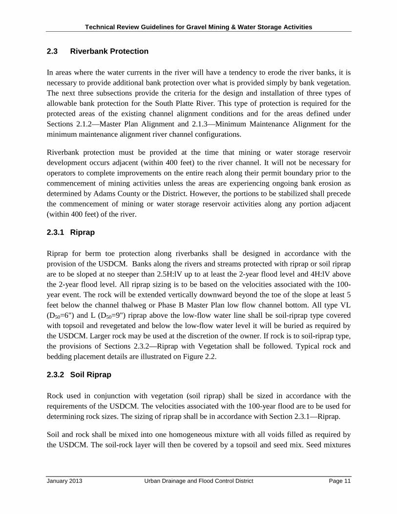
2.3 Riverbank Protection
In areas where the water currents in the river will have a tendency to erode the river banks, it is necessary to provide additional bank protection over what is provided simply by bank vegetation. The next three subsections provide the criteria for the design and installation of three types of allowable bank protection for the South Platte River. This type of protection is required for the protected areas of the existing channel alignment conditions and for the areas defined under Sections 2.1.2—Master Plan Alignment and 2.1.3—Minimum Maintenance Alignment for the minimum maintenance alignment river channel configurations.
Riverbank protection must be provided at the time that mining or water storage reservoir development occurs adjacent (within 400 feet) to the river channel. It will not be necessary for operators to complete improvements on the entire reach along their permit boundary prior to the commencement of mining activities unless the areas are experiencing ongoing bank erosion as determined by Adams County or the District. However, the portions to be stabilized shall precede the commencement of mining or water storage reservoir activities along any portion adjacent (within 400 feet) of the river.
2.3.1 Riprap
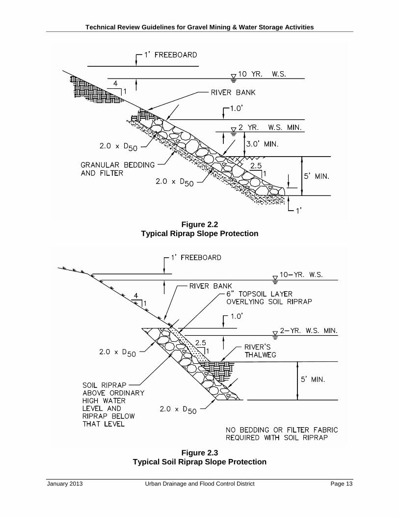
Riprap for berm toe protection along riverbanks shall be designed in accordance with the provision of the USDCM. Banks along the rivers and streams protected with riprap or soil riprap are to be sloped at no steeper than 2.5H:lV up to at least the 2-year flood level and 4H:lV above the 2-year flood level. All riprap sizing is to be based on the velocities associated with the 100-year event. The rock will be extended vertically downward beyond the toe of the slope at least 5 feet below the channel thalweg or Phase B Master Plan low flow channel bottom. All type VL (D50=6") and L (D50=9") riprap above the low-flow water line shall be soil-riprap type covered with topsoil and revegetated and below the low-flow water level it will be buried as required by the USDCM. Larger rock may be used at the discretion of the owner. If rock is to soil-riprap type, the provisions of Sections 2.3.2—Riprap with Vegetation shall be followed. Typical rock and bedding placement details are illustrated on Figure 2.2.
2.3.2 Soil Riprap
Rock used in conjunction with vegetation (soil riprap) shall be sized in accordance with the requirements of the USDCM. The velocities associated with the 100-year flood are to be used for determining rock sizes. The sizing of riprap shall be in accordance with Section 2.3.1—Riprap.
Soil and rock shall be mixed into one homogeneous mixture with all voids filled as required by the USDCM. The soil-rock layer will then be covered by a topsoil and seed mix. Seed mixtures
Technical Review Guidelines for Gravel Mining & Water Storage Activities
January 2013 Urban Drainage and Flood Control District Page 12
used in this mass are to conform with the Guidelines for Vegetation. Revegetation shall also include willow staking to encourage the growth of willow shrubbery in addition to native grasses.
Placement of the mass shall be accomplished in a manner to assure that no segregation of the various constituents occurs. No bedding will be allowed under soil riprap. Subsequent to the placement of the mass, a minimum of a 6-inch layer of topsoil will be placed above the rock. A typical detail of this installation is shown in Figure 2.3.
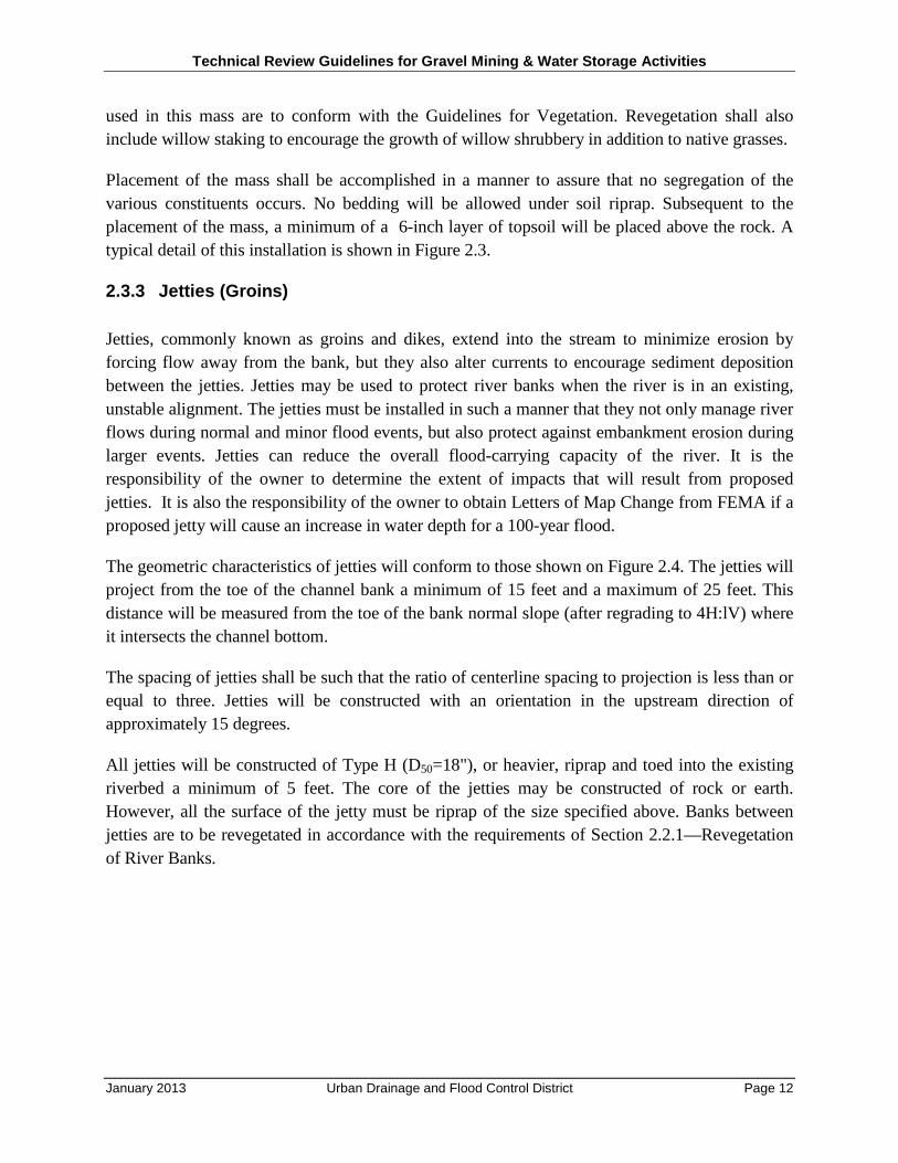
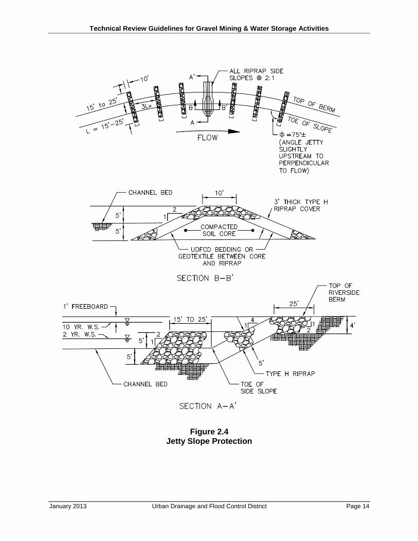
2.3.3 Jetties (Groins)
Jetties, commonly known as groins and dikes, extend into the stream to minimize erosion by forcing flow away from the bank, but they also alter currents to encourage sediment deposition between the jetties. Jetties may be used to protect river banks when the river is in an existing, unstable alignment. The jetties must be installed in such a manner that they not only manage river flows during normal and minor flood events, but also protect against embankment erosion during larger events. Jetties can reduce the overall flood-carrying capacity of the river. It is the responsibility of the owner to determine the extent of impacts that will result from proposed jetties. It is also the responsibility of the owner to obtain Letters of Map Change from FEMA if a proposed jetty will cause an increase in water depth for a 100-year flood.
The geometric characteristics of jetties will conform to those shown on Figure 2.4. The jetties will project from the toe of the channel bank a minimum of 15 feet and a maximum of 25 feet. This distance will be measured from the toe of the bank normal slope (after regrading to 4H:lV) where it intersects the channel bottom.
The spacing of jetties shall be such that the ratio of centerline spacing to projection is less than or equal to three. Jetties will be constructed with an orientation in the upstream direction of approximately 15 degrees.
All jetties will be constructed of Type H (D50=18"), or heavier, riprap and toed into the existing riverbed a minimum of 5 feet. The core of the jetties may be constructed of rock or earth. However, all the surface of the jetty must be riprap of the size specified above. Banks between jetties are to be revegetated in accordance with the requirements of Section 2.2.1—Revegetation of River Banks.
Technical Review Guidelines for Gravel Mining & Water Storage Activities
January 2013 Urban Drainage and Flood Control District Page 13
Figure 2.2 Typical Riprap Slope Protection
Figure 2.3 Typical Soil Riprap Slope Protection
Technical Review Guidelines for Gravel Mining & Water Storage Activities
January 2013 Urban Drainage and Flood Control District Page 14
Figure 2.4 Jetty Slope Protection
Technical Review Guidelines for Gravel Mining & Water Storage Activities
January 2013 Urban Drainage and Flood Control District Page 15
2.4 Pitside Bank Protection
The interior banks of reclaimed gravel pits require additional erosion protection beyond revegetation if the berm is to be protected from loss during large flood events. Protection of the pitside banks permits the reduction of top width of the berm provided it is accomplished using the requirements specified in the next five subsections.
Construction of the pitside bank protection will occur coincidentally with the construction of river bank erosion protection measures. That is, when mining activities abut against a river or stream, erosion protection of both the river bank and the pitside bank must be undertaken. In areas experiencing ongoing bank erosion as determined by District, it may be necessary to provide river bank protection prior to the commencement of mining operations, however, it will not be necessary to construct pitside bank protection measures until such time as gravel extraction is completed.
2.4.1 Riprap
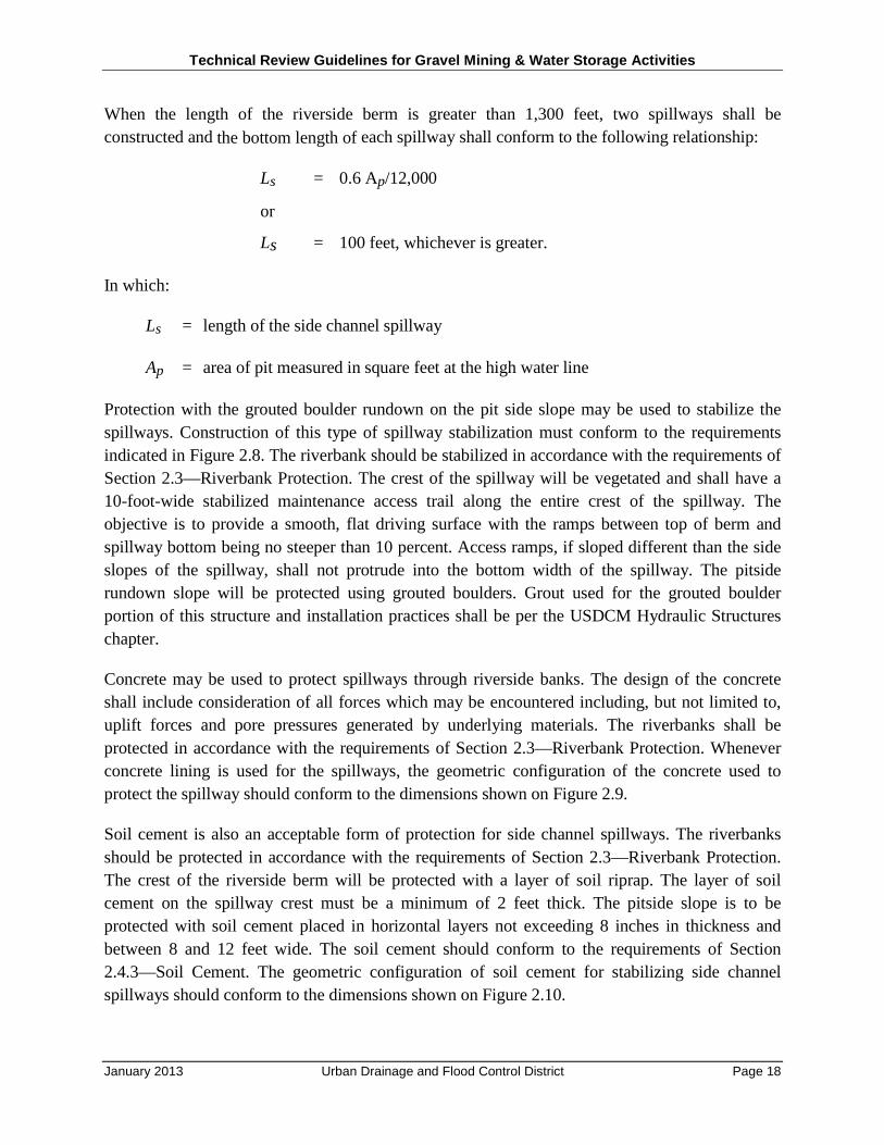
When riprap is used to stabilize the pitside slope, the rock shall be placed at a slope no steeper than 2.5H:1V. Riprap sizing will be in accordance with the safety factor method for flow on a plane sloping bed. The minimum safety factor (SF) shall be 1.25 (if SF = 1, riprap is at condition of incipient motion).
SF = 𝑐𝑜𝑠 𝜃 𝑡𝑎𝑛 ∅𝑛 𝑡𝑎𝑛∅ + 𝑠𝑖𝑛𝜃
n = 21 𝜏𝑠(𝑆𝑠−1)𝛾 𝐷50
τs = 𝛾𝑅𝑆
In which,
θ = face slope of pitside bank, in degrees to the horizontal
Ø = angle of repose of pitside bank construction materials in degrees
n = stability factor
Ss = specific gravity of riprap particles
γ = specific weight of water = 62.4 lbs/ft3
D50 = median riprap particle size, in feet
R = hydraulic radius at normal depth of flow down pitside slope, in feet
S = face slope of pitside bank, in feet per foot
Technical Review Guidelines for Gravel Mining & Water Storage Activities
January 2013 Urban Drainage and Flood Control District Page 16
SF = Safety factor
τs = Tractive force
Once the D50 is established using the above-described procedure, a gradation is to be selected. The gradation shall follow the general provisions specified in the USDCM. Material shall be placed in accordance with the criteria specified in the USDCM and as shown on Figure 2.5.
2.4.2 Soil Riprap
The methodology presented in Section 2.4.1—Riprap shall be used for sizing riprap when used in conjunction with vegetation on pitside banks. When soil riprap is to be used to stabilize the pitside banks of berms, the placement shall be in accordance with the requirements presented in Section 2.3.2—Soil Riprap.
2.4.3 Soil Cement
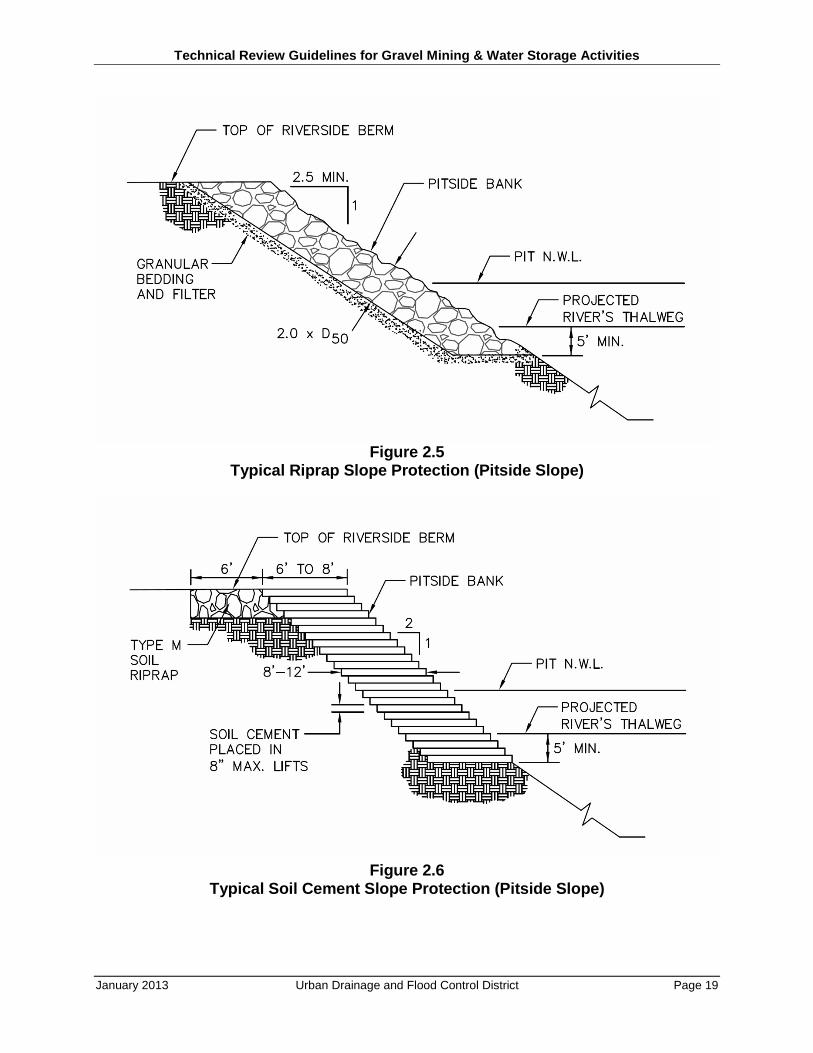
Soil cement may be used to stabilize the pitside slopes of riverside berms against erosion during overtopping. The soil cement must be placed on the pitside slope face in maximum 8-inch lifts at a width of 6 to 8 feet. The general geometric configuration of the soil cement stabilization will conform to the requirements as shown on Figure 2.6.
Soil cement will consist of a mixture of Portland cement, native soils (if conforming to gradation limitations) and water. Native soils may be used if they conform to the following three requirements: (1) the soil contains no material retained on a 2-inch sieve; (2) at least 55 percent of the material passes the No. 4 sieve; and (3) between 5 percent and 35 percent of the material passes the No. 200 sieve. The soil cement mixture should have a minimum of 10 percent Type 2 Portland cement as measured by weight. The moisture content of the soil shall range between 10 and 15 percent. In order to determine the proper cement content, optimum moisture content and maximum density of the soil cement mixture, standard laboratory tests must be performed. Refer to ASTM D558 for the test methods.
Mixing of the soil and cement may be accomplished at the site or off-site with mechanical means such as with mechanical batch mixing equipment specifically designed for the preparation of soil cement mixtures. Placement of the mixed and moistened soil cement mixture may be accomplished by standard construction means. Compaction will be accomplished with normal embankment compaction equipment, which shall include sheepsfoot roller to minimize weaknesses at the interface between successive lifts of soil cement.
Technical Review Guidelines for Gravel Mining & Water Storage Activities
January 2013 Urban Drainage and Flood Control District Page 17
2.4.4 Grouted Boulders
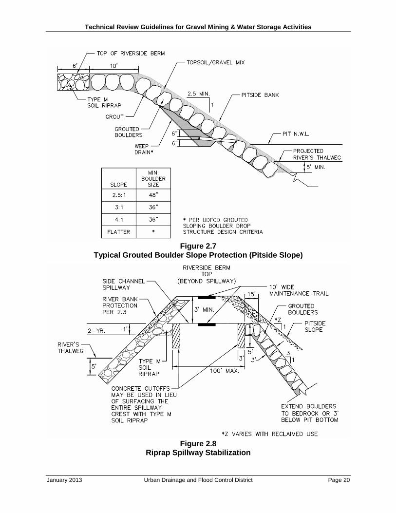
Grouted boulders may be used to stabilize the pitside slope of riverside berms against erosion from overtopping. The geometric configuration of the grouted boulders should conform to the requirements indicated on Figure 2.7 and the USDCM. For berms with a 4H:1V slope, the minimum boulder size shall be 36 inches. For berms with a 2.5H:1V pitside slope, the minimum boulder size shall be 48 inches. Boulders shall meet the specifications listed in the USDCM.
2.4.5 Side Channel Spillway
Side channel spillways may be provided between the river and the pit to minimize the potential for failure of the riverside berms. The stabilized spillway allows water to pass between the river and the pit and vice versa. A spillway on the upstream end of the pit and one at the downstream end of the pit will be required unless the pit is small and the differential head between the two ends is 2 feet or less, in which case one spillway will be sufficient. Side channel spillways should prevent the buildup of differential heads greater than 2 feet between the river and water in the pit.
Because of the nature of the hydraulic response of the spillways, the differential head cannot be completely eliminated. The objective is to minimize, to the extent possible, the differential head between water in the river and water in the pit when the riverside berms overtop.
The elevation of the side-channel spillway crest shall be approximately 1 foot above the 2-year flood elevation. When the riverside berm length of the gravel pit is less than 1,300 feet (i.e., assuming average slope of the river is 0.001 ft/ft), only one side channel spillway will be required, and it shall be located approximately in the midpoint of the berm. If the length of the berm is greater than 1,300 feet or the differential head between the two ends of the berm is no more than 2 feet, two spillways will be required and will be located along the berm approximately one-fifth of the berm length from the upstream and downstream ends of the berm.
When the length of the berm is less than 1,300 feet and the crest of the berm is no higher than one foot above the 2-year flow elevation, the spillway bottom length shall conform to the following geometric relationship:
Ls = Ap/12,000
or
Ls = 100 feet, whichever is greater.
In which
Ls = length of the side channel spillway
Ap = area of pit measured in square feet at the high water line
Technical Review Guidelines for Gravel Mining & Water Storage Activities
January 2013 Urban Drainage and Flood Control District Page 18
When the length of the riverside berm is greater than 1,300 feet, two spillways shall be constructed and the bottom length of each spillway shall conform to the following relationship:
Ls = 0.6 Ap/12,000
or
Ls = 100 feet, whichever is greater.
In which:
Ls = length of the side channel spillway
Ap = area of pit measured in square feet at the high water line
Protection with the grouted boulder rundown on the pit side slope may be used to stabilize the spillways. Construction of this type of spillway stabilization must conform to the requirements indicated in Figure 2.8. The riverbank should be stabilized in accordance with the requirements of Section 2.3—Riverbank Protection. The crest of the spillway will be vegetated and shall have a 10-foot-wide stabilized maintenance access trail along the entire crest of the spillway. The objective is to provide a smooth, flat driving surface with the ramps between top of berm and spillway bottom being no steeper than 10 percent. Access ramps, if sloped different than the side slopes of the spillway, shall not protrude into the bottom width of the spillway. The pitside rundown slope will be protected using grouted boulders. Grout used for the grouted boulder portion of this structure and installation practices shall be per the USDCM Hydraulic Structures chapter.
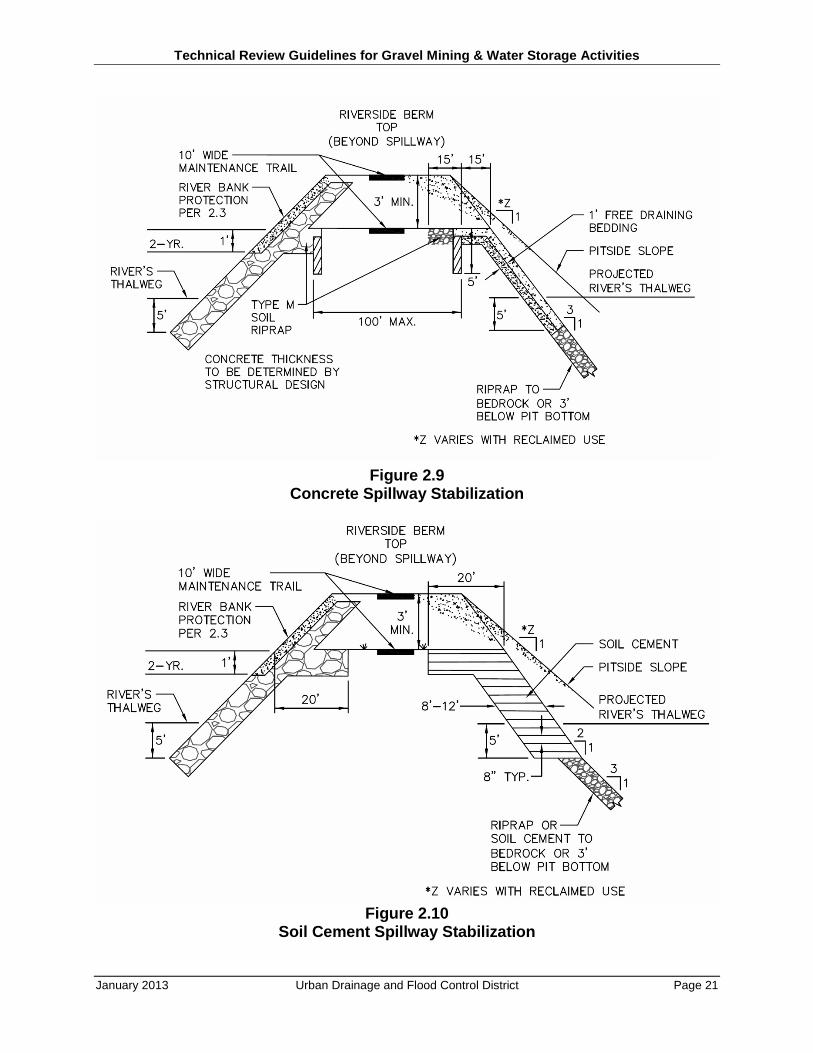
Concrete may be used to protect spillways through riverside banks. The design of the concrete shall include consideration of all forces which may be encountered including, but not limited to, uplift forces and pore pressures generated by underlying materials. The riverbanks shall be protected in accordance with the requirements of Section 2.3—Riverbank Protection. Whenever concrete lining is used for the spillways, the geometric configuration of the concrete used to protect the spillway should conform to the dimensions shown on Figure 2.9.
Soil cement is also an acceptable form of protection for side channel spillways. The riverbanks should be protected in accordance with the requirements of Section 2.3—Riverbank Protection. The crest of the riverside berm will be protected with a layer of soil riprap. The layer of soil cement on the spillway crest must be a minimum of 2 feet thick. The pitside slope is to be protected with soil cement placed in horizontal layers not exceeding 8 inches in thickness and between 8 and 12 feet wide. The soil cement should conform to the requirements of Section 2.4.3—Soil Cement. The geometric configuration of soil cement for stabilizing side channel spillways should conform to the dimensions shown on Figure 2.10.
Technical Review Guidelines for Gravel Mining & Water Storage Activities
January 2013 Urban Drainage and Flood Control District Page 19
Figure 2.5 Typical Riprap Slope Protection (Pitside Slope)
Figure 2.6 Typical Soil Cement Slope Protection (Pitside Slope)
Technical Review Guidelines for Gravel Mining & Water Storage Activities
January 2013 Urban Drainage and Flood Control District Page 20
Figure 2.7 Typical Grouted Boulder Slope Protection (Pitside Slope)
Figure 2.8 Riprap Spillway Stabilization
Technical Review Guidelines for Gravel Mining & Water Storage Activities
January 2013 Urban Drainage and Flood Control District Page 21
Figure 2.9 Concrete Spillway Stabilization
Figure 2.10 Soil Cement Spillway Stabilization
Technical Review Guidelines for Gravel Mining & Water Storage Activities
January 2013 Urban Drainage and Flood Control District Page 22
2.5 Lateral Berms
Lateral berms are berms constructed, or left in place, between pits and are often perpendicular to the general direction of flow of the South Platte River. These lateral berms separate gravel mining pits from one another. Lateral berms may be overtopped during major floods. When overtopped, the berms are subject to erosion due to the relatively high velocity flow and, in time, may fail resulting in a rapid release of water. This phenomenon can propagate in the downstream direction potentially increasing with each successive failure. By protecting lateral berms from catastrophic failure the likelihood of such downstream propagation can be significantly decreased.
The stabilization of lateral berms should be accomplished when mining reaches the berm location. When the lateral berm is proposed immediately upstream or downstream of an existing gravel pit, the stabilization proposed in this section must be implemented prior to the initiation of mining operations adjacent to the berm. When no mining has occurred downstream or upstream, the berm may be stabilized when mining reaches the berm location.
2.5.1 Type A Lateral Berms
Type A lateral berms are berms between adjacent gravel pits. Spacing between Type A lateral berms shall not exceed 1/2 mile as measured longitudinally along a river or a stream channel. The ½ mile spacing is consistent with potential road embankments or river access points for recreation or emergency repairs. These berms must be protected against headcutting to withstand overtopping during the 100-year flood. Erosive forces on the upstream face of lateral berms will be minimal with the exception of wave action caused by winds across the gravel pit’s water surface. The means for stabilizing the downstream face of the lateral berms are similar to those required to stabilize the pitside face of riverside berms and are as described in Section 2.5.3—Protection of Lateral Berms.
2.5.2 Type B Lateral Berms
Type B lateral berms also are berms between adjacent gravel pits. These berms differ from Type A lateral berms in their spacing. Type B lateral berms are located at major arterial road crossings as opposed to every half-mile. These berms are intended to provide a greater level of protection than the Type A lateral berms. This will be accomplished in part by the arterial road itself. The means for stabilizing the downstream face of Type B lateral berms are similar to those for Type A lateral berms and are described in Section 2.5.3—Protection of Lateral Berms.
2.5.3 Protection of Lateral Berms
Lateral berms are to be protected in a manner similar to the requirements for the pitside slopes of riverbank berms. In general, the crests of lateral berms are to be revegetated and the downstream
Technical Review Guidelines for Gravel Mining & Water Storage Activities
January 2013 Urban Drainage and Flood Control District Page 23
face of lateral berms are to be stabilized and protected using the methods proposed in Section 2.4—Pitside Bank Protection.
Riprap, soil riprap, soil cement and grouted boulders are all viable options for reinforcing both Type A and Type B lateral berms. These methodologies are to comply with the requirements of Section 2.4.1—Riprap, 2.4.2—Soil Riprap, 2.4.3—Soil Cement and 2.4.4—Grouted Boulders, respectively. The general geometric characteristics of lateral berm protection will conform to the individual details for the selected method of protection except that the protection needs to extend to bedrock or 3 feet below the pit floor.
2.5.4 Spillway for Type A Lateral Berms
A spillway will only be allowed for Type A lateral berm protection. The existing or future arterial road crossing associated with Type B lateral berms renders the spillway approach infeasible. The required length of the spillway for Type A lateral berms along the South Platte River will be determined using the following equation:
Ls1 = 2,500/H1.5
In which,
Ls1 = length of lateral berm spillway
H = height between top of berm and spillway crest
2.6 Berm-Top Width—Riverbank Berms
This section specifies the minimum top width for berms located adjacent to the South Platte River and subject to these Guidelines. The top-width requirements are specified to protect the berms from rapid failure during 100-year floods with overtopping lengths of time of two days duration. Such failure may result in the South Platte River flowing through the adjacent gravel pits causing the thalweg to drop, creating riverbed headcutting, resulting in loss of the river corridor and subsequently damaging property along the river. The berm-top width requirements consider long-term stability and safety along the South Platte River along with emergency equipment access and staging of emergency repair work, regional trails and the need to maintain a suitable Denver Metropolitan river corridor for multiple uses. Localized damages to the berms may result during large floods and may require periodic repair and maintenance.
The top widths are broken into two classifications, one for an unprotected river bank and one for protected river banks. Unless otherwise indicated, the requirements of Sections 2.3—Riverbank Protection and 2.4—Pitside Bank Protection constitute adequate bank protection.
Technical Review Guidelines for Gravel Mining & Water Storage Activities
January 2013 Urban Drainage and Flood Control District Page 24
The top widths are expressed as the distance between the top of the riverbank slope to the top of the pitside slope. The area between these two tops of slopes should be no steeper than 3 percent and as a minimum have a stand of vegetation that resembles the native vegetation along the site with reasonable closeness.
2.6.1 Existing Unstable Alignment
When the river is allowed to maintain an existing unstable alignment, and no bank protection is provided beyond the necessary revegetation, the minimum allowable top width of riverside berms will be 400 feet. This is the maximum setback requirement imposed on gravel mining operators.
When the river is maintained in an existing unstable alignment and the riverbank is protected in accordance with the requirements of Section 2.3—Riverbank Protection, the minimum allowable top width for the riverside berm will be 250 feet.
When the river is left in an existing unstable alignment and no riverbank protection is provided, but pitside slope protection is provided in accordance with the requirements of Section 2.4—Pitside Bank Protection, the allowable minimum top width will be 300 feet.
When the river is maintained in its existing unstable alignment and protection is provided for both the riverbank and the pitside slope in accordance with Sections 2.3—Riverbank Protection and 2.4—Pitside Bank Protection, the allowable minimum top width of the riverside berm will be 150 feet.
2.6.2 Master Plan Alignment and Minimum Maintenance Alignment
The Master Plan alignment and the minimum maintenance alignment are two cases in which the alignment of the river is predetermined and riverside bank stabilization is provided. The Master Plan alignment is mostly a modification of the existing alignment and is intended to reconcile the geometric requirements, property line constraints and constraints imposed by the existing river alignment.
Bank stabilization for the Master Plan alignment and the minimum maintenance alignment will be in accordance with those methodologies presented in Section 2.3—Riverbank Protection. For the Master Plan alignment, the various acceptable types of bank stabilization are presented in the Master Plan drawings and differ slightly from the requirements specified in Section 2.1—Types of River Alignment and 2.2—Revegetation of Berms. The principal differentiation is in the required stabilization scheme.
When the requirements of the Master Plan alignment or the minimum maintenance alignment are adhered to and, in addition to complying with the requirements for river bank stabilization, the pitside slope of riverside berms are stabilized in accordance with Section 2.4—Pitside Bank
Technical Review Guidelines for Gravel Mining & Water Storage Activities
January 2013 Urban Drainage and Flood Control District Page 25
Protection, the minimum allowable top width for riverside berms will be 100 feet. This is the minimum reasonable top width for staging emergency repair work or new construction, for regional trails and for maintaining a semblance of a river corridor.
2.7 Berm-Top Width—Lateral Berms
This section specifies the minimum top width for lateral berms located adjacent to the South Platte River and oriented perpendicular to the river. The top width requirement is specified to protect the berms from failure during floods, which result in an overtopping of lateral berms and cascading of water in the downstream direction. Instances of major flooding may result in some localized damage of the lateral berms in spite of the protection measures previously suggested. Routine repair and maintenance of all facilities associated with lateral berms must be performed. The flood criteria for design of lateral berms are for the 100-year flood as defined in the Master Plan.
2.7.1 Type A Lateral Berms
2.7.1.1 Unprotected Type A Lateral Berms
When Type A lateral berms are left in their unprotected natural state, the minimum allowable top width will be 250 feet. This assumes that the surface of the lateral berm is left in its native vegetated condition. If the lateral berm is to be reconstructed subsequent to excavation, the top of the lateral berm and the downstream slope must be revegetated in accordance with the requirements of Section 2.2—Revegetation of Berms.
2.7.1.2 Protected Type A Lateral Berm
When Type A lateral berms are protected in accordance with the requirements of Section 2.5.3—Protection of Lateral Berms, the minimum allowable top width will be 100 feet.
2.7.2 Type B Lateral Berms
The top width required for Type B lateral berms will exceed that required for Type A lateral berms because of the more critical nature of the Type B lateral berms. Type A lateral berms are designed to withstand flooding events up to the 100-year event having a 2-day duration; however, because of the possibility of more severe flood events, Type B lateral berms should withstand floods of higher magnitude than the 100-year event to avoid a catastrophic stair-step series of failures.
Technical Review Guidelines for Gravel Mining & Water Storage Activities
January 2013 Urban Drainage and Flood Control District Page 26
2.7.2.1 Unprotected Type B Lateral Berms
When Type B lateral berms are left unprotected, except for vegetation as specified in Section 2.2—Revegetation of Berms, the minimum allowable top width shall be 350 feet.
2.7.2.2 Protected Type B Lateral Berms
When Type B lateral berms are protected in accordance with the requirements of Section 2.5.3—Protection of Lateral Berms, the minimum allowable top width shall be 200 feet.
2.8 Berm-Top Widths
This section presents tables of berm-top widths based on the methodologies employed for berm stabilization.
Technical Review Guidelines for Gravel Mining & Water Storage Activities
January 2013 Urban Drainage and Flood Control District Page 27
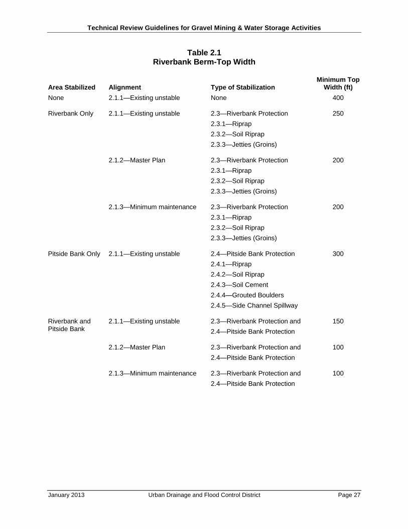
Table 2.1 Riverbank Berm-Top Width
Area Stabilized Alignment Type of Stabilization Minimum Top
Width (ft) None 2.1.1—Existing unstable None 400
Riverbank Only 2.1.1—Existing unstable 2.3—Riverbank Protection 250 2.3.1—Riprap 2.3.2—Soil Riprap 2.3.3—Jetties (Groins)
2.1.2—Master Plan 2.3—Riverbank Protection 200 2.3.1—Riprap 2.3.2—Soil Riprap 2.3.3—Jetties (Groins)
2.1.3—Minimum maintenance 2.3—Riverbank Protection 200 2.3.1—Riprap 2.3.2—Soil Riprap 2.3.3—Jetties (Groins)
Pitside Bank Only 2.1.1—Existing unstable 2.4—Pitside Bank Protection 300 2.4.1—Riprap 2.4.2—Soil Riprap 2.4.3—Soil Cement 2.4.4—Grouted Boulders 2.4.5—Side Channel Spillway
Riverbank and Pitside Bank
2.1.1—Existing unstable 2.3—Riverbank Protection and 150 2.4—Pitside Bank Protection
2.1.2—Master Plan 2.3—Riverbank Protection and 100 2.4—Pitside Bank Protection
2.1.3—Minimum maintenance 2.3—Riverbank Protection and 100 2.4—Pitside Bank Protection
Technical Review Guidelines for Gravel Mining & Water Storage Activities
January 2013 Urban Drainage and Flood Control District Page 28
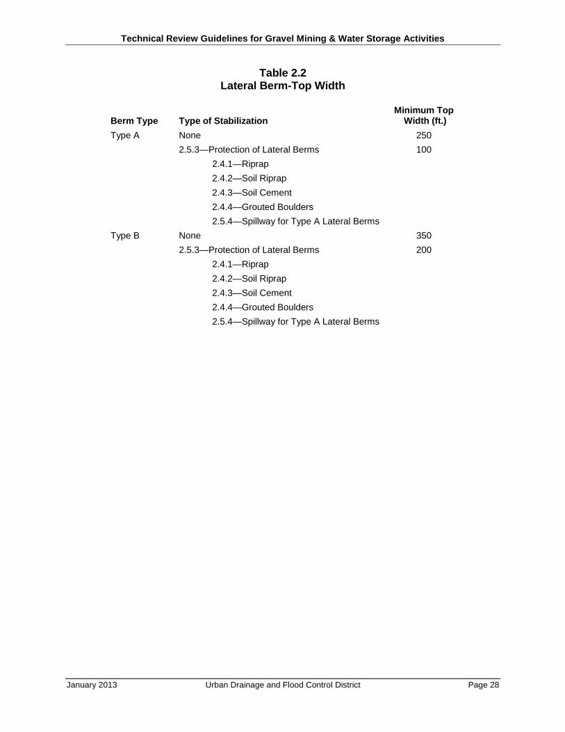
Table 2.2 Lateral Berm-Top Width
Berm Type Type of Stabilization Minimum Top
Width (ft.) Type A None 250 2.5.3—Protection of Lateral Berms 100 2.4.1—Riprap 2.4.2—Soil Riprap 2.4.3—Soil Cement 2.4.4—Grouted Boulders 2.5.4—Spillway for Type A Lateral Berms Type B None 350 2.5.3—Protection of Lateral Berms 200 2.4.1—Riprap 2.4.2—Soil Riprap 2.4.3—Soil Cement 2.4.4—Grouted Boulders 2.5.4—Spillway for Type A Lateral Berms
Technical Review Guidelines for Gravel Mining & Water Storage Activities
January 2013 Urban Drainage and Flood Control District Page 29
3.0 IN-RIVER GRAVEL MINING
Mining in the mainstream of the South Platte River or any of its tributaries will not be permitted because the impact instream sand and gravel extraction has on the stability of the river upstream and downstream of the extraction point, which results in widespread and severe damages to properties, utilities and infrastructure along the river. This section on In-River Gravel Mining was part of the Guidelines published in 1987 and is included in this revision for information purposes only. It is not to be construed as conditions for the approval of insteam mining.
All operators proposing to mine the mainstream of the river shall demonstrate conclusively that they will not adversely impact the river and the properties, roads, bridges, diversion structures and utilities on the river for a distance of four miles in the upstream and downstream directions, in addition to taking the mitigating measures required in Chapter 3.0 and obtaining all other permits required by federal and state law.
Instream mining of the river includes not only mines which are ongoing in the channel of the South Platte River or its tributaries, but also includes offstream gravel mines when it is proposed to relocate the river through such offstream gravel mines. The impacts of relocating a river or a stream through an off channel pit are equivalent to those associated with the actual mining of the South Platte riverbed or its tributaries. As such, these requirements will apply to mines which actively mine within a river or stream channel as well as mining operations which propose to relocate a river or a stream through previously mined pits.
3.1 Groundwater Impacts
The extraction of gravel and other products from the bed of the South Platte River or its tributaries shall be done in such a manner as to prevent damage to adjoining property. This requires that the adjacent groundwater table not be altered, or, if alteration takes place, the owner of any groundwater rights shall be compensated commensurate with any damage that may occur. It also requires compliance with applicable Colorado water laws and regulations governing injury to existing water rights as well as compliance with applicable federal and Colorado water quality laws and regulations.
3.2 Sediment Transport
Instream gravel pits may result in the deposition of significant portions of the sediment load carried by the South Platte River or its tributaries. The gravel operator must show that his mining will not adversely affect the stability of the river or a stream downstream from his site.
Technical Review Guidelines for Gravel Mining & Water Storage Activities
January 2013 Urban Drainage and Flood Control District Page 30
3.3 Water Quality
Long-range water quality concerns can be significant in an instream gravel pit lake because of pollution constituents in the river at the location of the excavation. Any operations in the river shall be required to comply with applicable federal and Colorado water quality laws and regulations.
3.4 Side Slope Protection
Excavation of materials from the bed of the South Platte River must be done in a manner that does not jeopardize the stability of the channel banks. To accomplish this, the side slopes of the river bank above the pre-mining channel invert should be extended downward. This slope will generally be between 2.5 and 4 feet horizontal for every one foot vertical. The actual slope will depend on the method of bank stabilization proposed at the site.
3.5 Headcutting Control
When mining in the riverbed is permitted, gravel operators must prevent long-term headcutting from propagating in the upstream direction. The removal of material from the riverbed results in excessive headcutting, which endangers structures upstream that cross the river or stream or that are located in the adjacent banks of same. It is imperative that the operators install positive controls as specified below to prevent headcutting of any type from occurring upstream as a result of gravel extraction from the river bottom.
3.5.1 Control Structures
The impacts of the instream gravel extraction must be mitigated with a positive structural control at the upstream end of the instream pit. The structure must be protected from failure through a wide variety of flow rates, gravel pit depths and inconsistent soil properties.
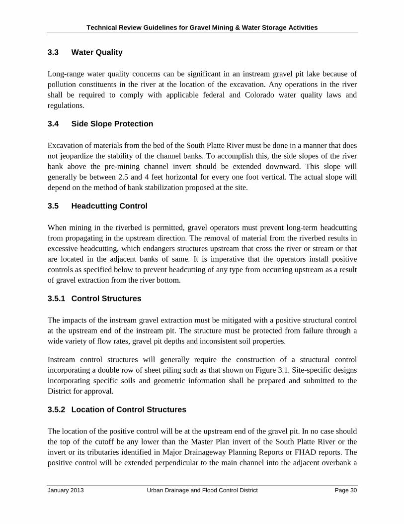
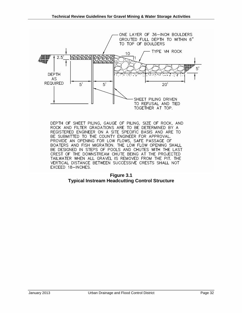
Instream control structures will generally require the construction of a structural control incorporating a double row of sheet piling such as that shown on Figure 3.1. Site-specific designs incorporating specific soils and geometric information shall be prepared and submitted to the District for approval.
3.5.2 Location of Control Structures
The location of the positive control will be at the upstream end of the gravel pit. In no case should the top of the cutoff be any lower than the Master Plan invert of the South Platte River or the invert or its tributaries identified in Major Drainageway Planning Reports or FHAD reports. The positive control will be extended perpendicular to the main channel into the adjacent overbank a
Technical Review Guidelines for Gravel Mining & Water Storage Activities
January 2013 Urban Drainage and Flood Control District Page 31
minimum of 250 feet. Where gravel pits exist in the overbank, a positive control should extend across the lateral berms, as well.
3.5.3 Overbank Protection
In areas where there is no overbank gravel mining operation in existence and none is proposed, the overbank cutoff may be less substantial. In these cases, the overbank cutoff may consist of Type M (USDCM) riprap placed in a trench 6 feet deep and 3 feet wide and extending across the entire floodplain. This protection will begin at the end of the embedment of the structural positive control as discussed in Section 3.5.2—Location of Control Structures.
3.6 Upstream Protection
Because of the increased energy grade line slope immediately upstream of the gravel pit cutoff structure, it will be necessary to protect the river upstream from general degradation and against potential damages to bridges, utility crossings and property.
3.6.1 Extent of Upstream Protection
The protection required upstream of the crest of the pit cutoff structure shall extend upstream a minimum of 175 feet.
3.6.2 Type of Protection
The type of protection used to protect the river bottom shall be riprap or cobble. The required size of protection shall be determined according to the requirements of the USDCM Major Drainage Chapter. Use of boulders for the construction of grade control or drop structures satisfying the proper boulder sizing will be allowed.
Technical Review Guidelines for Gravel Mining & Water Storage Activities
January 2013 Urban Drainage and Flood Control District Page 32
Figure 3.1 Typical Instream Headcutting Control Structure
Technical Review Guidelines for Gravel Mining & Water Storage Activities
January 2013 Urban Drainage and Flood Control District Page 33
4.0 RECLAMATION
The mineral rules and regulations, published by the Colorado Mined Land Reclamation Board, establish the requirements for reclamation of mined lands in the State of Colorado. These requirements must be satisfied and adhered to for the life of the mine in order to obtain a mining permit for the extraction of gravel. The requirements presented in this document supplement those of the Mined Land Reclamation Board and recognize the special riverine corridor stability needs. In no case do the requirements of this document imply that the requirements of the Mined Land Reclamation Board, as a minimum, should not be adhered to.
4.1 Recreational Criteria
When gravel pit lakes are to be reclaimed as recreational amenities, the side slopes of the lakes should be sloped at a minimum of 5H:lV for a distance from the top of the berm to a point 8 feet under the normal water surface. There the slope can be at 2H:lV to the lake bottom. Where concentrated swimming is to be actively encouraged, side slopes of 20H:lV or flatter are recommended in the beach areas.
Irregularities in the lake shorelines are required for variety in the environment and to enhance wildlife habitat. These irregularities also help protect the banks from wave action. Other recreational or wildlife features, such as islands, may be required by local government.
Corridors must be provided for access to recreational areas and maintenance trails. These corridors should be incorporated into riverside berms, or through other portions of the lease properties if developed as part of an overall recreational master plan by the operators or by the local governments. A minimum corridor of 100 feet is necessary to accommodate multiple recreational uses. This river corridor minimum width should be maintained on both sides of the river for its entire length. The recreational corridor may be contained within the required top width of riverside berms.
4.2 Revegetation Criteria
Revegetation of all disturbed areas will be required; and disturbed areas will require a stormwater management plan and permit. The revegetation should be installed in conformance with the Guidelines for Vegetation and must meet the approval of the Colorado Mined Land Reclamation Board.
The goal of revegetation is to reestablish the historic ground cover as closely as possible to promote the return of the historic animal population, to protect areas from erosion by wind and water and to improve the aesthetics of the area. To accomplish this, revegetation must be undertaken at the earliest opportunity. Revegetation must begin as soon as the slope has attained its required configuration subject to the seeding criteria specified in Guidelines for Vegetation.

Technical Review Guidelines for Gravel Mining & Water Storage Activities
January 2013 Urban Drainage and Flood Control District Page 34
When slopes are in areas that will be inactive for periods in excess of six months, vegetation must be re-established.
Technical Review Guidelines for Gravel Mining & Water Storage Activities
January 2013 Urban Drainage and Flood Control District Page 35
5.0 WATER STORAGE RESERVOIRS
Extensive development of municipal water storage reservoirs has occurred within or adjacent to the 100-year floodplain. Many of the water storage reservoirs are converted from gravel pits and, therefore, these Guidelines shall apply to water storage reservoirs within or adjacent to the 100-year floodplain.
Existing and future sand and gravel mining, mine reclamation and water supply reservoir development may limit the ability of the floodplain to store flood volumes and adequately convey flood flows. Many of the mining operations and water supply reservoirs, however, are located within the floodway, and by regulation cannot cause a rise in 100-year water surface elevations. Requiring mining operations and water supply lakes to keep all associated berms at or below the existing ground elevation will protect floodplain storage and may even provide compensatory flood storage for the volume lost due to development. Setback criteria developed relative to the top of bank as delineated in the Master Plan can be uniformly defined and applied by all jurisdictions along the river corridor.
Z:\Project Files\12\121-030\121-030.000\Deliverables\Guidelines\Technical Review Guideline for Gravel Mining Activities 01-2013.docx
Wright Water Engineers, Inc., 2490 W. 26th Avenue, Ste. 100A, Denver, CO 80211 Tel. 303/480-1700; Fax. 303/480-1020, e-mail:[email protected]
TECHNICAL MEMORANDUM
To: Laura Kroeger, UDFCD David Bennett, UDFCD
From: Wright Water Engineers, Inc.
Date: July 3, 2012
Re: Technical Review Guidelines for Gravel Mining Activities
This memo is intended to provide a basis for a letter report to the Urban Drainage and Flood Control District (UDFCD) that would summarize the status of the Guidelines and to provide a scope of services to bring the Guidelines up-to-date and to answer UDFCD’s questions.
The guidelines were initially conceptually formulated for the South Platte River Master Plan, and then for Adams County. A final document was completed for Adams County in November 1985. Two years later, in 1987, the UDFCD published its Guidelines. The parameters and design guides in the 1987 publication received wide support by June 1985 from the industry, from the State of Colorado, and others after four to five months of intense meetings and negotiations.
The originally proposed top widths of riverside and lateral berms were significantly reduced from about January to June 1985 as criteria were negotiated and worked out with diverse interests, including parks and recreation people with interests in trails and boating. Supporting computations and procedures can be developed to support the 1987 parameters and to prepare procedures for considering hardship variances for reservoirs.
FINDINGS
• Reasonableness of Guidelines. The 1987 gravel guidelines are well accepted and reasonable and with general support from those interviewed.
• Main Concerns with Use of Guidelines. A significant concern with the use of the guidelines is that of a catastrophic multi-pit failure that, while causing a downstream flood surge, would allow the river to be routed through a series of gravel pits with a resulting adverse river regime change.
• Technical Basis. There are no specific sets of calculations and/or processes that can be directly connected to most of the twelve berm top width parameters in Table 2.1 and 2.2, although there were calculations in the file that formed the basis of initially recommended parameters. The parameters as published, instead, represent the combined knowledge and experience of the many dozens of individuals who conferred on original and early WWE draft documents and criteria.
Memorandum to Laura Kroeger and David Bennett July 3, 2012 Page 2
The specific criteria of the guidelines were originally intended to be based upon scientific principles and practical objectives related to rock product mining of the 1980s. Original and initial guideline drafts in early 1985 were modified via significant industry and regulatory agency input during the spring of 1985. The technical criteria given in the 1987 guidelines are based upon principles, policy and criteria from the 1969 UDFCD, the 1984-1985 Master Plan, industry practices and economics, regulatory agency needs and the civil and geotechnical engineering professions. The parameters are supportable.
• Water Storage Facilities. The 1987 guidelines were formulated primarily for gravel mining, not for large municipal public work reservoirs that are operated and maintained by governmental agencies. Nevertheless, the guidelines are applicable to water storage facilities for the river protection purposes.
• Variances. As with most guidelines for public works design and construction, variances may be accommodated so long as they meet or exceed the intent and function of the published standards.
Variances are acceptable for the 1987 guidelines for the “Typical Minimum Maintenance Alignment (Figure 2.1).
Referring to the guideline Figures 2.2 through 2.10 for protection and stabilization, variances are allowable if the intent and objectives of the figures are met.
In regard to the top widths of riverside berms it would appear that variances could be considered if public health, safety and welfare were not compromised, the test being the meeting of specific objectives and design criteria, but not compromising on safety factors or the berm top width needed for maintenance, emergency and rescue operations or stability for floods of up to the standard project flood (500-year) and when the gravel pit, water storage facility, or adjacent pit, was empty.
For the purpose of evaluating variance requests to the UDFCD guidelines, sets of evaluation and technical criteria and computations would need to be provided for each parameter in the guideline that is proposed for change.
CONSULTATIONS
Interviews were conducted to obtain comments and suggestions on the gravel mining guidelines. Pertinent comments are listed.
Tim J. Randle, U.S. Bureau of Reclamation, Manager, Sedimentation and River Hydraulics Group, Denver Federal Center
• The guideline berm top widths are quite reasonable.
• There are numerous mechanisms that could cause a gravel pit berm failure.
Memorandum to Laura Kroeger and David Bennett July 3, 2012 Page 3
o Dynamic river cutting and filling
o Overtopping of berm
o Animal burrows
o Erosion of river bank at outside of curve.
• Concern was expressed for domino-like set of lateral berm failures.
• Q500 may not be a critical condition; test many conditions/recurrence intervals.
• South Platte River south of 104th Avenue appeared especially susceptible to failures due to the lake storage density.
• Riprap protection must be adequate.
• There is concern about continued maintenance once the gravel operator is gone, i.e., who would repair a failure?
• The river bed in Adams County seems to have a gravel bed, based on photos reviewed.
Mike Stevens, Geomorphologist, Consultant to UDFCD since 1982
• Do not let gravel pit berms fail. Keep river out of pits.
• Avoid piping failures (animal burrows can be especially problematic).
• Do not change from 1984 Master Plan discharges.
• Rely on State Engineer Dam Safety criteria for failure analysis and USBR Design of Small Dams.
• River breached a gravel pit dike near Chatfield, the river flowed in and then out. This is an example, on a relatively small scale, of the potential for what could happen in the event of failure.
• Top widths must be adequate to facilitate emergency repairs.
Bill McCormick, Chief Dam Safety Branch, Colorado Division of Water Resources
• Dam Safety Branch has gravel pit concerns primarily when the lake level is higher than the river.
Memorandum to Laura Kroeger and David Bennett July 3, 2012 Page 4 Ben Urbonas, Private Consultant, Former Chief of Master Planning for UDFCD
• Many meetings were held in 1985 on the guidelines.
• Original top widths tended to be more conservative than those listed in the June 1985 draft and the November 1985 Adams County Guidelines.
• The main concern about the gravel pit layouts are the lateral berms and the potential stair-step/domino failure.
Berhan Keffelew, Colorado Mined Land Reclamation Board (MLRB) – in charge of Adams County gravel reviews
• MLRB uses the UDFCD 1987 guidelines.
• The Guidelines are satisfactory; they are good.
• The top width of berms are per the 1987 guide, but they are open to negotiation if adequacy of a variance can be demonstrated.
• Lesser top widths are infrequent due to cost of proving equivalency.
• Thornton reported to Berhan Keffelew -- “fair” with top width design; however, one cannot be too conservative on berm design.
• A deficiency in design reviews is that only one gravel pit considered at a time. It is important to look at the cumulative effect on safety of gravel pits.
• However, Thornton has only one gravel mine permit in its name. M1986-146 is for wildlife habitat. Thornton takes over gravel mines that have already been converted to a storage lake and the reclamation is complete and the permit/project is released.
• The Division of Reclamation, Mining and Safety (DRMS)/MLRB does not track properties after final reclamation. At that point it is the owner and Adams County that are in charge.
Jessica Barbier, Project Engineer, Denver Water
• Jessica was project engineer during Denver Water conversion from pits to reservoirs. She handled Cat Reservoir and is familiar with Miller Reservoir.
• No “setback” issue on Cat Reservoir due to Xcel land buffer.
• For Miller Reservoir, Denver Water worked with UDFCD to stabilize river due to small existing setback (pre-1987).
• Hazelton pit may have been filled to meet setback.
Memorandum to Laura Kroeger and David Bennett July 3, 2012 Page 5
• Gravel pit storage is now under Greg Gulley of Dam Safety.
TECHNICAL BASIS FOR PARAMETERS
The 1987 gravel mining guidance stemmed from UDFCD’s concerns about river channel stability, Mike Steven’s geomorphological report of 1983, the 1984-1985 Master Plan for the South Platte River, and the desire of Adams County and the Colorado Rock Products Association for order. Formulation of the guidance document was supported by Adams County and financially by the Colorado Rock Product Association.
The early work of WWE (March 1984) on riverside berm top widths for the South Platte River Master Plan dealt with ordinary gravel mining with embankments of native soil. Criteria testing in 1984 included test cases with various input data.
From this 1984 analysis by Mark Glidden, P.E. (who was with WWE at this time) it was concluded that the berms would need armoring to resist failure during the 100-year flood event.
Using a D75 of one inch as a test case, it was concluded that a top width of 385 feet was required based on a safety factor of 2.0 plus a minimum buffer of 50 feet. However, when the armoring was raised to 3 inch gravel, the top width was reduced greatly. The resulting conclusion was that riverside berms would have a riprap face with filter and a slope of 3:1, including a 50 foot buffer and a top width of 100 feet for the Master Plan.
Early analyses of berm top widths demonstrated that if the riverside berms are protected against failure with adequate riprap and toe protection, the theoretical top width could be much reduced.
It is evident that the designated berm top widths were not controlled solely by erosion and sedimentation science, but by the following considerations.
• Need to provide for bank side river recreation trails.
• Importance of providing for emergency repair staging and work
• Desirability of providing a long and reasonable riparian river corridor that would not have the character of a narrow flood control channel.
• Allowing for development of water recreation boating with suitable put-ins and take-outs coupled with provisions for water rescue operators.
The 100-foot minimum width for fully protected riverside berms is a reasonable non-technical based parameter. Using technical analyses only, one could likely show that a narrow top width of say 30 feet, would suffice. However, this would not be consistent with good river corridor planning and was not the objective in the 1985-1987 period.
Memorandum to Laura Kroeger and David Bennett July 3, 2012 Page 6 STORAGE VS. MINING GUIDANCE
The general mining guidance criteria are applicable for use with the gravel pits for water storage from the standpoint of protecting the river. However, as a result of the dense and numerous reservoirs built and planned for the South Platte River in Adams County, and because of their proximity to each other, it would be wise to suggested an analysis of cumulative impacts as desired by the Colorado DMRS.
ALLOWABLE VARIANCES
The guideline criteria for review of gravel mining are reasonable. They have been approved by the gravel industry and many agencies and have withstood the test of time. However, variances can be considered. The supporting documentation for proposed variances from the guidelines should be thorough and exacting and should be based upon a cumulative effect and compatibility with upstream and downstream development, as suggested by the DMRS. Considering the many factors involved with the basis for the guidance criteria, it would seem unlikely that the 2012 revision to the 1987 document would reduce the 100-foot top width for riverbank berms, the 100-foot top width for Type A lateral berms, or the 200-foot top width for Type B lateral berms.
CONCLUSIONS
The 1987 Guidelines for gravel mining do not have readily available detailed supporting technical calculations for the berm top widths. However, a technical basis can be prepared coupled with the logic and policy to support the parameters. Since 1987, the use of gravel pits for municipal storage has become common. The guidelines are suitable for water storage facilities. There is no reason that variances cannot be requested and considered, however, non-structural constraints would likely forestall any change to the top widths of fully protected berms to less than the stated values.
Z:\Project Files\12\121-030\121-030.000\Deliverables\CD of Reports for UDFCD\Technical Review Memo\Technical Review Memo.doc