Embed Size (px)
Citation preview
Category A Large Heavy Duty Bus Technical Specifications Page 1 of 146
EXHIBIT E-6
Technical Specifications Heavy Duty Bus
Oregon Department of Transportation
In collaboration with the
Oregon Department of Administrative Services

DASPS-2234-19 Category A Large Heavy Duty Bus Technical Specifications Page 2 of 146
Table of Contents 1 GENERAL ..................................................................................................................................16
1.1 Scope ........................................................................................................................16
1.2 Referenced Publications ..........................................................................................16
1.3 Overall Requirements ..............................................................................................16
1.4 Worker and Protective Measures ............................................................................17
1.5 Water Test Description ............................................................................................18
1.6 Total Bus Operation .................................................................................................18
1.7 Weight ......................................................................................................................19
1.8 Capacity ....................................................................................................................19
1.9 Service Life ...............................................................................................................19
1.10 Maintenance and Inspection ...................................................................................19
1.11 Interchangeability ....................................................................................................20
1.12 Training ....................................................................................................................20
1.13 Train the Trainer ...................................................... Error! Bookmark not defined.
1.14 Operator Orientation ...............................................................................................21
1.15 Maintenance Orientation ........................................................................................21
1.16 Technical ..................................................................................................................22
1.17 OEM .........................................................................................................................22
1.18 Operating Environment ...........................................................................................23
1.19 Secure Lines, Hoses, and Wiring ..............................................................................23
1.20 Fire Safety ................................................................................................................23
1.21 Fire Suppression.......................................................................................................23
1.22 Respect for the Environment ...................................................................................24
2 NOISE .......................................................................................................................................24
2.1 Interior Noise ...........................................................................................................24
2.2 Exterior Noise ...........................................................................................................24
3 DIMENSIONS ............................................................................................................................24

DASPS-2234-19 Category A Large Heavy Duty Bus Technical Specifications Page 3 of 146
3.1 Physical Size .............................................................................................................24
3.2 Bus Length ................................................................................................................24
3.3 Bus Width .................................................................................................................25
3.4 Bus Height ................................................................................................................25
3.5 Step Height ...............................................................................................................25
3.6 Underbody Clearance ..............................................................................................25
3.7 Ramp Clearances ......................................................................................................25
3.8 Ground Clearance ....................................................................................................25
3.9 Floor Height..............................................................................................................26
3.10 Interior Headroom ...................................................................................................26
3.11 Aisle Width ...............................................................................................................26
4 VEHICLE PERFORMANCE ..........................................................................................................26
4.1 Power Requirements ...............................................................................................26
4.2 Top Speed ................................................................................................................27
4.3 Gradability ................................................................................................................27
4.4 Acceleration .............................................................................................................27
4.5 Hybrid .......................................................................................................................28
4.6 Electric ......................................................................................................................28
4.7 Battery Charger ........................................................................................................28
4.8 Operating Range ......................................................................................................28
4.9 Diesel ........................................................................................................................28
4.10 CNG ..........................................................................................................................28
4.11 Hybrid .......................................................................................................................29
4.12 Battery Electric .........................................................................................................29
4.13 Fuel Economy/ or Energy Economy/Range Test (Design Operating Profile) ...........29
4.14 Hybrid .......................................................................................................................29
4.15 Electric ......................................................................................................................29
5 POWERPLANT...........................................................................................................................30
5.1 Automatic Engine Protection/Shutdown Override Feature ....................................30
5.2 Excessive Idle Shutdown ..........................................................................................31
5.3 Fast-Idle System .......................................................................................................32

DASPS-2234-19 Category A Large Heavy Duty Bus Technical Specifications Page 4 of 146
5.4 Engine (CNG) ............................................................................................................32
6 Propulsion System (Hybrid) .....................................................................................................32
6.1 Propulsion System Service .......................................................................................32
6.2 Primary Propulsion Unit and Traction Motor ..........................................................32
6.3 Energy Storage and Controller .................................................................................33
6.4 Hybrid System Controller (HSC) ...............................................................................33
6.5 Prime Power Unit (PPU) ...........................................................................................33
6.6 Propulsion System Description (Electric) .................................................................33
6.7 Propulsion System Service .......................................................................................33
6.8 Propulsion System Controller ..................................................................................34
6.9 Traction System .......................................................................................................34
6.10 Energy Storage and Controller .................................................................................34
6.11 Battery Management System ..................................................................................34
6.12 Energy Storage System ............................................................................................35
6.13 Battery Thermal Management ................................................................................35
6.14 Cooling Systems .......................................................................................................35
6.15 Motor Cooling System (Electric) ..............................................................................35
6.16 Transmission Cooling ...............................................................................................36
6.17 Electric Drive System Cooling ..................................................................................36
6.18 Engine Cooling .........................................................................................................36
6.19 Electronic Fans .........................................................................................................38
6.20 Screen in Front of Radiator ......................................................................................38
6.21 Standard Requirement for Coolant Filtration ..........................................................38
6.22 Self-Cleaning ............................................................................................................38
6.23 Standard Mounting Design ......................................................................................38
6.24 Cooling Fan Controls ................................................................................................38
6.25 Charge Air Cooling ...................................................................................................38
6.26 Transmission Cooling ...............................................................................................39
6.27 Hybrid Drive System Cooling ...................................................................................39
6.28 Electric Drive System Cooling ..................................................................................39
6.29 Transmission (Conventional Powertrain) ................................................................39

DASPS-2234-19 Category A Large Heavy Duty Bus Technical Specifications Page 5 of 146
6.30 Retarder Transit Coach ............................................................................................40
6.31 Retarder- Regenerative Braking (Electric Bus) ........................................................40
6.32 Braking Resistors ......................................................................................................40
6.33 Engine Brake (Commuter Coach) .............................................................................41
6.34 Standard Requirement for Retarder Activation ......................................................41
6.35 Accessible Retarder Disable Switch .........................................................................41
6.36 Mounting ..................................................................................................................41
6.37 Service (Electric) .......................................................................................................41
6.38 Service (Diesel, CNG or Hybrid) ...............................................................................42
6.39 Engine Oil Pressure and Coolant Temperature Gauges...........................................42
6.40 Engine Air Cleaner ....................................................................................................42
6.41 Hydraulic Systems ....................................................................................................42
6.42 Hydraulic System Sensors ........................................................................................43
6.43 Fluid Lines ................................................................................................................43
6.44 Fittings and Clamps ..................................................................................................43
6.45 Charge Air Piping ......................................................................................................43
6.46 Radiator ....................................................................................................................44
6.47 Oil and Hydraulic Lines .............................................................................................44
7 FUEL .........................................................................................................................................44
7.1 Fuel Lines..................................................................................................................44
7.2 Fuel Lines (Electric buses) ........................................................................................44
7.3 Fuel Lines, CNG ........................................................................................................45
8 DESIGN AND CONSTRUCTION ..................................................................................................45
8.1 Design and Construction, Diesel, (Not applicable to Electric Buses) .......................45
8.1.1 Fuel Tank(s) ..............................................................................................................45
8.1.2 Installation ...............................................................................................................45
8.1.3 Labelling ...................................................................................................................46
8.1.4 Fuel Filler ..................................................................................................................46
8.1.5 Dry-break fuel filler ..................................................................................................46
8.2 Design and Construction, CNG .................................................................................46
8.2.1 Fuel Containers/Cylinders ........................................................................................46

DASPS-2234-19 Category A Large Heavy Duty Bus Technical Specifications Page 6 of 146
8.2.2 U.S. Applications: .....................................................................................................47
8.2.3 Installation ...............................................................................................................47
8.2.4 Labelling ...................................................................................................................47
8.2.5 Pressure Relief Devices (PRDs) ................................................................................47
8.2.6 Valves .......................................................................................................................48
8.2.7 Fuel Filler ..................................................................................................................48
8.2.8 Fueling System .........................................................................................................48
8.2.9 Defueling System .....................................................................................................49
9 EMISSIONS AND EXHAUST .......................................................................................................49
9.1 Exhaust Emissions ....................................................................................................49
9.2 Exhaust System ........................................................................................................49
9.3 Exhaust After Treatment..........................................................................................49
9.4 Diesel Exhaust Fluid Injection ..................................................................................49
9.5 Particulate After Treatment .....................................................................................50
9.6 Emissions and Exhaust Electric buses ......................................................................50
9.7 Fire Suppression System ..........................................................................................50
10 STRUCTURE ..............................................................................................................................50
10.1 General Design .........................................................................................................50
10.2 Altoona Testing ........................................................................................................51
10.3 Altoona Test Report Submitted to Authorized Purchaser Prior to Start of Bus Production ...............................................................................................................51
10.4 Structural Validation - Baseline Structural Analysis.................................................51
10.5 Distortion .................................................................................................................51
10.6 Resonance and Vibration .........................................................................................51
10.7 Engine or Motor Compartment Bulkheads ..............................................................52
10.8 Crashworthiness ......................................................................................................52
10.9 Corrosion ..................................................................................................................53
10.10 Corrosion-Resistance Requirements for Exposed and Interior Surfaces of Tubing Below Lower Window Level ....................................................................................53
10.11 Towing ......................................................................................................................53
10.12 Lifted (Supported) Front Axle and Flat Towing Capability (additional requirement)53

DASPS-2234-19 Category A Large Heavy Duty Bus Technical Specifications Page 7 of 146
10.13 Jacking ......................................................................................................................54
10.14 Yellow Pads ..............................................................................................................54
10.15 Hoisting ....................................................................................................................54
11 FLOOR.......................................................................................................................................54
11.1 Design (Transit Coach) .............................................................................................54
11.2 Design (Commuter) ..................................................................................................55
11.3 Reserved...................................................................................................................55
11.4 Strength....................................................................................................................55
11.5 Construction .............................................................................................................55
11.6 Pressure-Preserved Plywood Panel .........................................................................56
11.7 Construction (Commuter Coach) .............................................................................56
12 Platforms ..................................................................................................................................56
12.1 Driver’s Area ............................................................................................................56
12.2 Driver’s Platform ......................................................................................................57
12.3 Farebox ....................................................................................................................57
12.4 Rear Step Area to Rear Area ....................................................................................57
13 WHEEL HOUSING .....................................................................................................................58
13.1 Design and Construction ..........................................................................................58
13.2 Design and Construction (Transit Coach) ................................................................58
14 CHASSIS ....................................................................................................................................58
14.1 Suspension - General Requirements........................................................................58
14.2 Alignment .................................................................................................................59
14.3 Springs and Shock Absorbers - Suspension Travel ..................................................59
14.4 Damping ...................................................................................................................59
14.5 Lubrication - Standard Grease Fittings ....................................................................59
14.6 Kneeling....................................................................................................................59
15 WHEELS AND TIRES ..................................................................................................................60
15.1 Wheels .....................................................................................................................60
15.2 Painted Steel ............................................................................................................60
15.3 Tires ..........................................................................................................................60
15.4 Steering ....................................................................................................................60

DASPS-2234-19 Category A Large Heavy Duty Bus Technical Specifications Page 8 of 146
15.5 Steering Axle Transit Coach - Solid Beam or Independent suspension type Axle and Grease-Type Front Bearings and Seals ....................................................................61
15.6 Steering and Tag Axles Commuter Coach ................................................................61
15.7 Steering Wheel - Turning Effort ...............................................................................61
15.8 Steering Wheel - General .........................................................................................61
15.9 Steering Column - Tilt ..............................................................................................62
15.10 Steering Wheel - Telescopic Adjustment .................................................................62
16 Drive Axle ................................................................................................................................62
16.1 Non-Drive Axle .........................................................................................................63
16.2 Tag Axles (Commuter Coach) ...................................................................................63
16.3 Turning Radius .........................................................................................................63
17 BRAKES .....................................................................................................................................64
17.1 Service Brake ............................................................................................................64
17.2 Air-Actuated Brakes .................................................................................................64
17.3 Automatic Traction Control .....................................................................................64
17.4 Friction Material ......................................................................................................64
17.5 Hubs .........................................................................................................................64
17.6 Drum Brakes .............................................................................................................65
17.7 Disc Brakes on All Axles (optional) ...........................................................................65
17.8 Hub and Drums Commuter Coach ...........................................................................66
17.9 Parking/Emergency Brake ........................................................................................66
17.9.1 Air Brakes ................................................................................................................66
17.9.2 Hydraulic Brakes .....................................................................................................66
18 INTERLOCKS .............................................................................................................................66
18.1 Passenger Door Interlocks .......................................................................................66
18.2 Requiring Accelerator Interlock Whenever Front Doors Are Open .........................66
18.3 Pneumatic System - General ....................................................................................67
18.4 Air Compressor ........................................................................................................67
18.5 Air Lines and Fittings ................................................................................................67
18.6 Air Reservoirs ...........................................................................................................68
18.7 Air System Dryer ......................................................................................................68

DASPS-2234-19 Category A Large Heavy Duty Bus Technical Specifications Page 9 of 146
19 ELECTRICAL, ELECTRONIC AND DATA COMMUNICATION SYSTEMS .......................................69
19.1 Overview ..................................................................................................................69
19.2 Modular Design ........................................................................................................70
19.3 Environmental and Mounting Requirements ..........................................................70
19.4 Hardware Mounting .................................................................................................72
20 GENERAL ELECTRICAL REQUIREMENTS BATTERIES .................................................................73
20.1 Low-Voltage Batteries (24V) ....................................................................................73
20.2 Two 8D Battery Units ...............................................................................................73
20.3 Battery Cables ..........................................................................................................73
20.4 Jump-Start Connector ..............................................................................................74
20.5 Battery Compartment ..............................................................................................74
20.6 Auxiliary Electronic Power Supply ...........................................................................75
20.7 Master Battery Switch .............................................................................................75
20.8 Single Switch ............................................................................................................75
20.9 Low-Voltage Generation and Distribution ...............................................................75
20.10 Circuit Protection .....................................................................................................76
20.11 Grounds ....................................................................................................................76
20.12 Low Voltage/Low Current Wiring and Terminals ....................................................76
20.13 Electrical Components .............................................................................................78
20.14 Electrical Compartments..........................................................................................78
20.15 General Electronic Requirements ............................................................................78
20.16 Wiring and Terminals ...............................................................................................78
20.17 Discrete I/O (Inputs/Outputs) ..................................................................................79
20.18 Shielding ...................................................................................................................79
20.19 Communications ......................................................................................................79
20.20 Radio Frequency (RF) ...............................................................................................79
20.21 Audio ........................................................................................................................80
21 MULTIPLEXING .........................................................................................................................81
21.1 General .....................................................................................................................81
21.2 System Configuration ...............................................................................................81
21.3 I/O Signals ................................................................................................................81

DASPS-2234-19 Category A Large Heavy Duty Bus Technical Specifications Page 10 of 146
22 DATA COMMUNICATIONS .......................................................................................................82
22.1 General .....................................................................................................................82
22.2 Drivetrain Level ........................................................................................................82
22.3 Diagnostics, Fault Detection and Data Access .........................................................82
22.4 Programmability (Software) ....................................................................................83
23 MULTIPLEX LEVEL .....................................................................................................................83
23.1 Data Access ..............................................................................................................83
23.2 Diagnostics and Fault Detection ..............................................................................83
23.3 Provide Mock-Up Board ...........................................................................................83
23.4 Programmability (Software) ....................................................................................83
23.5 Electronic Noise Control ..........................................................................................84
24 DRIVER PROVISIONS, CONTROLS AND INSTRUMENTATION ...................................................84
24.1 Driver’s Area Controls - General ..............................................................................84
24.2 Glare .........................................................................................................................84
24.3 Visors/Sun Shades Front and Side Sun Shade/Visor ................................................84
24.4 Driver’s Controls ......................................................................................................85
24.5 Normal Bus Operation Instrumentation and Controls ............................................85
24.6 Driver Foot Controls .................................................................................................93
24.7 Pedal Angle ..............................................................................................................93
24.7.1 Pedal Dimensions and Position ................................................................................93
24.7.2 1 to 2 in. Between Brake and Accelerator Pedals ....................................................93
24.8 Brake and Accelerator Pedals ..................................................................................93
24.8.1 Adjustable Brake and Accelerator Pedals ................................................................93
24.9 Driver Foot Switches ...............................................................................................93
24.9.1 Floor-Mounted Foot Control Platform.....................................................................93
24.9.2 Turn Signal Controls ................................................................................................94
24.9.3 Foot Switch Control .................................................................................................94
24.9.4 Other Floor-Mounted Controls ................................................................................94
24.10 Driver’s Amenities ...................................................................................................94
24.11 Coat Hook ................................................................................................................94
24.12 Drink Holder ............................................................................................................94

DASPS-2234-19 Category A Large Heavy Duty Bus Technical Specifications Page 11 of 146
24.13 Windshield Wipers...................................................................................................95
24.14 Windshield Washers ................................................................................................95
25 DRIVER’S SEAT ..........................................................................................................................95
25.1 Dimensions ...............................................................................................................95
25.2 Seat Pan Cushion Length..........................................................................................95
25.3 Seat Pan Cushion Height Dimensions ......................................................................95
25.4 Seat Pan Cushion Slope ............................................................................................96
25.5 Seat Base Fore/Aft Adjustment ...............................................................................96
25.6 Seat Pan Cushion Width ...........................................................................................96
25.7 Seat Suspension .......................................................................................................96
25.8 Seat Back - Width .....................................................................................................96
25.9 Height .......................................................................................................................96
25.10 Headrest ...................................................................................................................96
25.11 Seat Back Lumbar Support .......................................................................................96
25.12 Seat Back Angle Adjustment ....................................................................................97
25.13 Seat Belt ...................................................................................................................97
25.14 Seat Control Locations .............................................................................................97
25.15 Seat Structure and Materials - Cushions .................................................................97
25.16 Cushion Materials ....................................................................................................97
25.17 Pedestal ....................................................................................................................97
26 MIRRORS ..................................................................................................................................97
26.1 Exterior Mirrors ........................................................................................................97
26.2 Interior Mirrors ........................................................................................................98
27 WINDOWS ................................................................................................................................98
27.1 General .....................................................................................................................98
27.2 Windshield ...............................................................................................................99
27.3 Glazing ......................................................................................................................99
27.4 Driver’s Side Window ...............................................................................................99
27.5 Side Windows .........................................................................................................100
28 HEATING, VENTILATING AND AIR CONDITIONING ................................................................100
28.1 Capacity and Performance .....................................................................................100

DASPS-2234-19 Category A Large Heavy Duty Bus Technical Specifications Page 12 of 146
28.2 Controls and Temperature Uniformity ..................................................................103
28.3 Manual Mode Selection of Climate Control System ..............................................103
28.4 Manually Adjustable Temperature Control Set Point ...........................................103
28.5 Air Flow - Passenger Area ......................................................................................104
28.6 Air Flow - Driver’s Area ..........................................................................................104
28.7 Controls for the Climate Control System (CCS) .....................................................104
28.8 Driver’s Compartment Requirements....................................................................105
28.9 Air Filtration ...........................................................................................................105
28.10 Cleanable Filters .....................................................................................................106
28.11 Roof Ventilators - One Roof Ventilators ................................................................106
28.12 Reserve ...................................................................................................................106
28.13 Maintainability .......................................................................................................106
28.14 Entrance/Exit Area Heating ...................................................................................106
28.15 Floor-Level Heating ................................................................................................107
28.15.1 Transit Coach .........................................................................................................107
28.15.2 Commuter Coach ...................................................................................................107
29 EXTERIOR PANELS, FINISHES AND EXTERIOR LIGHTING ........................................................107
29.1 Design .....................................................................................................................107
29.2 Materials ................................................................................................................108
29.3 Roof-Mounted Equipment .....................................................................................108
29.4 Pedestrian Safety ...................................................................................................108
29.5 Repair and Replacement - Side Body Panels .........................................................108
29.6 Easily Replaceable Lower Side Body Panels ...........................................................108
29.7 Rain Gutters ...........................................................................................................108
29.8 License Plate Provisions .........................................................................................109
29.9 Fender Skirts ..........................................................................................................109
29.10 Standard Splash Aprons .........................................................................................109
29.11 Service Compartments and Access Doors - Access Doors .....................................109
29.12 Access Door Latch/Locks ........................................................................................110
29.13 Bumpers - Location ................................................................................................111
29.14 Front Bumper .........................................................................................................111
DASPS-2234-19 Category A Large Heavy Duty Bus Technical Specifications Page 13 of 146
29.15 Bicycle Racks ..........................................................................................................112
29.16 Rear Bumper ..........................................................................................................112
29.17 Bumper Material ....................................................................................................112
30 FINISH AND COLOR ................................................................................................................113
30.1 Appearance ............................................................................................................113
30.2 Decals, Numbering and Signing .............................................................................114
30.3 Passenger Information ...........................................................................................114
30.4 Exterior Lighting .....................................................................................................115
30.5 Backup Light/Alarm ................................................................................................116
30.6 Doorway Lighting ...................................................................................................116
30.7 Service Area Lighting (Interior and Exterior) .........................................................116
31 INTERIOR PANELS AND FINISHES ...........................................................................................117
31.1 General Requirements ...........................................................................................117
31.2 Interior Panels ........................................................................................................117
31.3 Driver Area Barrier .................................................................................................117
31.4 Wheel-Well-to-Ceiling Configuration of Driver’s Barrier .......................................117
31.5 Full-Height (Floor-to-Ceiling) Configuration of Driver’s Barrier (optional) ............117
31.6 Driver Security Enclosure Door ..............................................................................118
31.7 Modesty Panels ......................................................................................................118
31.8 Front End ................................................................................................................118
31.9 Rear Bulkhead ........................................................................................................118
31.10 Headlining ..............................................................................................................119
31.11 Fastening ................................................................................................................119
31.12 Insulation ...............................................................................................................119
31.13 Floor Covering ........................................................................................................119
31.14 Interior Lighting......................................................................................................120
31.15 Passenger ...............................................................................................................120
31.16 Driver Area .............................................................................................................121
31.17 Seating Areas .........................................................................................................122
31.18 Vestibules/Doors ....................................................................................................122
31.19 Step Lighting...........................................................................................................122

DASPS-2234-19 Category A Large Heavy Duty Bus Technical Specifications Page 14 of 146
31.20 Ramp Lighting ........................................................................................................122
32 Fare Collection .......................................................................................................................122
33 Interior Access Panels and Doors ..........................................................................................123
33.1 Floor Panels ............................................................................................................123
34 PASSENGER ACCOMMODATIONS ..........................................................................................124
34.1 Passenger Seating- Arrangements and Seat Style .................................................124
34.2 Hip-to-Knee Room .................................................................................................124
34.3 Foot Room ..............................................................................................................124
34.4 Aisles ......................................................................................................................125
34.5 Dimensions .............................................................................................................125
34.6 Structure and Design .............................................................................................125
34.7 Construction and Materials ...................................................................................127
34.8 Passenger Assists ...................................................................................................127
34.9 Assists .....................................................................................................................127
34.10 Front Doorway .......................................................................................................128
34.11 Vestibule ................................................................................................................128
34.12 Rear Doorway(s) ....................................................................................................129
34.13 Overhead ................................................................................................................129
34.14 Longitudinal Seat Assists ........................................................................................129
34.15 Wheel Housing Barriers/Assists .............................................................................129
34.16 Passenger Doors.....................................................................................................129
34.17 Closing Force ..........................................................................................................132
34.18 Actuators ................................................................................................................132
34.19 Rear Door Interlocks ..............................................................................................133
34.20 Emergency Operation ............................................................................................133
34.21 Door Control ..........................................................................................................133
34.22 Door Controller - Five-Position or Two Momentary Push Buttons Driver’s Door Controller ...............................................................................................................133
34.23 Door Open/Close - Operator-Controlled Front and Passenger-Controlled Rear Doors with Provision for Driver Override ..............................................................134
35 Accessibility Provisions .........................................................................................................134
35.1 Loading Systems .....................................................................................................134

DASPS-2234-19 Category A Large Heavy Duty Bus Technical Specifications Page 15 of 146
35.2 Dimensions and capabilities: .................................................................................134
35.3 Two Forward-Facing Wheelchair Securement Locations ......................................135
35.4 Wheelchair Securing System .................................................................................135
35.5 Interior Circulation .................................................................................................136
36 SIGNAGE AND COMMUNICATION .........................................................................................137
36.1 Cables and Accessories ..........................................................................................137
36.2 Display and Display Illumination ............................................................................138
36.3 Sign Enclosures ......................................................................................................139
36.4 Electronic System Requirements: ..........................................................................139
36.5 Operator Control Unit (OCU) .................................................................................139
36.6 Programming .........................................................................................................140
36.7 Message Memory Transfer and UPDATE ...............................................................140
36.8 Interconnecting Cabling .........................................................................................140
36.9 Dash Mounted Mechanical Sign ............................................................................140
36.10 Passenger Information and Advertising - Interior Displays ...................................140
36.11 Exterior Displays.....................................................................................................140
36.12 Passenger Stop Request/Exit Signal .......................................................................141
36.13 Communications - Camera Surveillance System ...................................................141
36.14 Mobile Radio System .............................................................................................143
36.15 Electronics/Equipment Compartment ...................................................................144
36.16 Radio Mounting .....................................................................................................144
36.17 Radio Transmitter ..................................................................................................144
36.18 Antenna ..................................................................................................................144
36.19 Antenna and Access Panel .....................................................................................145
36.20 Public Address System ...........................................................................................145
36.21 Automatic Passenger Counting ..............................................................................146

DASPS-2234-19 Category A Large Heavy Duty Bus Technical Specifications Page 16 of 146
TECHNICAL SPECIFICATIONS
1 GENERAL
1.1 Scope
The State of Oregon Department of Administrative Services (DAS) in collaboration with the Oregon State Department of Transportation, Rail and Public Transportation Division establish a price agreement(s) for the purchase of heavy-duty transit buses that will provide the best value and selection to purchasers while maximizing passenger appeal in appearance, comfort, and safety, combined with excellence in reliability, operating characteristics, and economy of operation. Heavy-duty buses purchased under the 2019 RFP are 35’, 40’, and 45’; with low-floor or high floor (over the road buses); and diesel power, hybrid drive, standard drive, CNG, or electric propulsion system; or any combination thereof. Buses must have a minimum expected life of twelve (12) years or 500,000 miles, whichever comes first, and are intended for a wide possible spectrum of passengers, including children, adults, the elderly, and people with disabilities. The buses must be Altoona tested and meet any other bus testing requirements under MAP-21.
Attached to Contractor’s RFP proposal was a comprehensive listing of optional equipment that is incorporated into the Price Agreement. Authorized Purchasers ordering under this Price Agreement shall be able to select optional equipment from this listing without incurring cost for additional engineering hours for any changes in optional equipment.
1.2 Referenced Publications
The documents or portions thereof referenced within this specification must be considered part of the requirements of the specification. The edition indicated for each referenced document is the current edition, as of the date of the Oregon issuance of this specification.
1.3 Overall Requirements
The Contractor shall ensure that the application and installation of major bus subcomponents and systems are compliant with all such subcomponent vendors’ requirements and recommendations. Contractor and Authorized Purchaser shall identify subcomponent vendors that shall submit installation/application approval documents with the completion of a pilot or lead bus. Components used in the vehicle must be of heavy-duty design and proven in transit service.
Chassis structure (integrity & corrosion) 12 year/500,000 Miles
Engine 2 year/unlimited Miles
Transmission 5 year/ 300,000 Miles

DASPS-2234-19 Category A Large Heavy Duty Bus Technical Specifications Page 17 of 146
Axle Rear & Front 5 Year/300,000 Miles
Basic Bus Structure 3 year/150,000 Miles
The buses must afford features essential for safe, efficient and comfortable operation by the operator. This implies the utmost in road and traffic visibility under all driving conditions and adequate means for safe passenger movement. The bus must be maneuvered easily in normal and heavy traffic. Contractor must conform to these specifications and the product they furnish must be of first-class quality, and workmanship, and must be of the best obtainable in the various trades. The design of the body, chassis, and equipment, which the manufacturer proposes to furnish, must be such as to produce a vehicle of substantial and durable construction in all respects.
To the extent practical, all systems, major sub-systems, and components must be individually and permanently labeled with Manufacturer, Part Number, and Serial Number. Label is to be located, in each instance, for easiest access for reading while installed for use in the bus. List of all systems, subsystems, and components must accompany each bus either CD, DVD or flash drive.
The manufacturer must use either FC300, FC510 and FC 195 hoses or Parker brand equivalent for all flexible lines except A/C and discharge from the air compressor to the wet tank.
The manufacturer shall be responsible for providing all parts or details which make each bus complete and ready for service, even though such part(s) or details(s) are not mentioned in these specifications.
All buses must be in compliance with the Americans with Disabilities Act (ADA). These buses must be new, unused, current model specifically designed for ether intra or inter-city service as applicable and substantially manufactured in the United States (in accordance with "Buy America" requirements). These units must meet all Federal requirements applicable to this type of vehicle. Buses provided under this contract shall be 35-foot, and 40-foot, 45-foot in length, 102 inches wide, nominal with a low or high floor designs.
1.4 Worker and Protective Measures
All bolts or rods passing through wood must be sealed with zinc chromate or other approved sealing compound. Where wood and wood are placed together, all outer edges of wood, as well as the edges of holes, cutouts and notches must be coated with a linseed oil and titanium dioxide sealer or zinc chromate or other appropriate sealing compound.
All exterior light fixtures must be fitted to the contour of the bus body and adequately sealed to prevent entrance of water.
All rubber seals on ventilator doors and compartment cabinet doors must be placed in 'U' shaped channels to firmly hold the rubber in place. Equally, self-adhering closed cell neoprene seals may be used, without 'U' channels.
DASPS-2234-19 Category A Large Heavy Duty Bus Technical Specifications Page 18 of 146
All burrs and sharp edges must be dressed to prevent injury to passengers and employees, or damage to their clothing.
All buses must be subjected to water tests simulating the severe rain conditions experienced in the Oregon State environment. Windows, escape hatches, doors, etc. are subject to an approved water test to be conducted at the manufacturer’s facility by the manufacturer and shall be observed by the Authorized Purchaser’s inspector if applicable. Inspector(s). Water testing may be verified by further testing at the Authorized Purchaser’s Maintenance Facility prior to the acceptance of each vehicle if test observation or verification of leak repair is missed on or not observed by the Authorized Purchaser’s Inspector on any bus built. Any bus that fails to pass the water test shall be corrected by the Contractor. The retest/corrective repair cycle shall repeat until the leak(s) have been eliminated to the Authorized Purchaser’s satisfaction.
1.5 Water Test Description
The roof, roof hatches, front cap, rear cap, sidewalls, passenger windows, driver’s windows, destination sign windows, windshields, wheel wells and all doors of all coaches must be water tested prior to the delivery of each unit as follows:
1. The water test shall consist of a series of nozzles which are strategically located around the perimeter of the vehicle so as to spray water over the entire surface of the vehicle.
2. The nozzles must eject a volume of water no less than 2.6 gallons per minute per nozzle under a pressure of no less than 22 lbs. per square inch measured at the nozzle tip.
3. The Contractor shall be required to water test each vehicle under the conditions described above for no less than 30 minutes (15 minutes with A/C off, then 15 minutes with A/C on) to ensure there are no water leaks in the bus.
4. Bus road testing must be conducted immediately after the water test. All road tests shall be conducted by the OEM on-site inspectors and verified by Authorized Purchaser inspector.
Contractor shall take the necessary steps of corrective action to repair any leaks found as a result of the described test and shall repeat the 30-minute water test to ensure that corrective steps have been successful. This process shall be repeated until no leaks are found. Documentation of each bus shall be kept by the manufacturer as to the location of the leak, what caused the leak to occur and must describe the repair action taken to prevent the leak from reoccurring.
If the Contractor’s bus manufacturing process water test differs from the water test process and criteria described above, then any deviations shall be approved by the Agency.
1.6 Total Bus Operation
Total bus operation must be evaluated during road tests. The purpose of the road tests is to observe and verify the operation of the bus as a system and to verify the functional

DASPS-2234-19 Category A Large Heavy Duty Bus Technical Specifications Page 19 of 146
operation of the subsystems that can be operated only while the bus is in motion. Each bus must be driven for a minimum of 25 miles during the road tests. The plan shall be submitted to the Authorized Purchaser for approval.
All zerk grease testing fittings must be accessible from a pit location with a standard straight nose grease gun.
All vehicles must be road-tested.
1.7 Weight
It must be a design goal to construct each bus as light in weight as possible without degradation of safety, appearance, comfort, traction or performance.
Buses at a capacity load must not exceed the tire factor limits, brake test criteria or structural design criteria. All buses must be weighed at a certified scale and weight slips must be included in the packet from the builder with each coach.
1.8 Capacity
The vehicle must be designed to carry the gross vehicle weight, which must not exceed the bus GVWR.
1.9 Service Life
The minimum useful design life of the bus in transit service must be at least twelve (12) years or 500,000 miles. It must be capable of operating at least 40,000 miles per year, including the 12th year.
1.10 Maintenance and Inspection
Scheduled maintenance tasks shall be related and shall be, in accordance with the manufacturer’s recommended preventative maintenance schedule (along with routine daily service performed during the fueling operations).
Test ports must be installed for commonly checked functions on the bus, such as air intake, exhaust, hydraulic, pneumatic, charge-air and engine cooling systems, engine, transmission, etc.
Quantity tags must be installed in a highly visible location next to the fill location for the engine, transmission, differential, power steering, etc. These quantity tags must be permanently attached and must list the manufacturers recommended fill quantity.
Engines and/or Transmissions, if used, must be supplied with the Titan Probalyzer # 0D1014 fittings or KP push button sampling valves (or equivalents) installed that are easy to access: device and location selection to be made at pre-production meeting. (All electric powered buses are excluded from this requirement.)
The coach manufacturer shall give prime consideration to the routine problems of maintaining the vehicle. All coach components and systems, both mechanical and electrical, which must require periodic physical Work or inspection processes, must be

DASPS-2234-19 Category A Large Heavy Duty Bus Technical Specifications Page 20 of 146
installed so that a minimum of time is consumed in gaining access to the critical repair areas. It must not be necessary to disassemble portions of the coach structure and/or equipment such as seats and flooring under seats in order to gain access to these areas. Each coach must be designed to facilitate the disassembly, reassembly, servicing or maintenance, using tools and equipment that are normally available as standard commercial items.
Requirements for the use of unique specialized tools must be minimized. The body and structure of the coach must be designed for ease of maintenance and repair. Individual panels or other equipment which may be damaged in normal service must be repairable or replaceable. Ease of repair must be related to the vulnerability of the item to damage in service.
Contractor shall provide a list of all special tools and pricing required for maintaining this equipment. List shall be submitted as a supplement during Request for Quote process.
NOTE: Tools such as compartment door and compartment access keys must not be included in the special tool list and shall be furnished for each coach.
1.11 Interchangeability
Unless otherwise agreed, all units and components procured under this Contract, whether provided by Suppliers or manufactured by the Contractor, must be duplicates in design, manufacture and installation to ensure interchangeability among buses in each order group in this procurement. This interchangeability must extend to the individual components as well as to their locations in the buses. These components must include, but are not limited to, passenger window hardware, interior trim, lamps, lamp lenses and seat assemblies. Components with non-identical functions must not be, or appear to be, interchangeable. Any one component or unit used in the construction of these buses must be an exact duplicate in design, manufacture and assembly for each bus in each order group in this Contract. Contractor shall identify and secure approval for any changes in components or unit construction provided under this Agreement.
In the event that the Contractor is unable to comply with the interchangeability requirement, the Contractor must notify the Agency and obtain the Agency’s prior written approval, including any changing in pricing.
Agency shall review proposed product changes on a case-by-case basis and shall have the right to require extended warranties to ensure that product changes perform as least as well as the originally supplied products.
1.12 Training
At the time of delivery, Contractor shall provide, at no cost, hands-on equipment features and operation overview. The Contractor shall provide an appropriate program of instruction targeted to the operator, servicing, and maintenance personnel. This may be accomplished through a combination of Authorized Purchaser on-site and Contractor

DASPS-2234-19 Category A Large Heavy Duty Bus Technical Specifications Page 21 of 146
and/or supplier site training. Training may consist of Train the Trainer, Technical, and OEM. All offered trainings shall be priced separate from the bus prices.
Programs must include training and testing materials, specific tools, equipment, and identified training aids. The Authorized Purchaser shall indicate the training desired and, by mutual agreement, when the performance period is to begin. The Contractor shall provide Authorized Purchaser with an electronic copy using Portable Document Format (PDF) of all applicable lesson plans, training guides, student workbooks, along with any other videos, transparencies or additional instructional training aids. The Contractor shall inform the Authorized Purchaser of any training support equipment and/or supplies required to be supplied by the Authorized Purchaser for the Contractor portion of the training.
All training instructors must be competent to teach the course area they are instructing. Further, all instructors shall speak English and have a complete understanding of the English language. If the instructor or vendor presenter lacks the skill or knowledge to provide instruction, or cannot communicate with the students, the Authorized Purchaser reserves the right to request that the instructor be replaced and the area of training be repeated.
1.13 Reserved
1.14 Operator Orientation
The Contractor shall provide complete training and instruction for Authorized Purchaser designated Operations personnel. Class size is not to exceed 10 employees per session. The program must include, but not be limited to the following:
Operator Compartment; Controls and Switches; Warning Indicators and Gauges; Seat Adjustment; Door Control; Walk Around Inspection; Compartment-by-Compartment Explanation; Mirror Adjustments; Climate Control system; Driving Instruction; Turns; Braking; Transmission; Backing; Wheelchair Ramp Equipment; Controls; Safety; Emergency Procedures; Securing Wheelchairs and Riders; Loading and Unloading.
Each trainee will be given an opportunity to operate the bus with the Contractor's instructor on board. The training shall be delivered on a schedule coordinated between the Authorized Purchaser’s training department and the Contractor. The number of sessions to be provided will be negotiated between the Authorized Purchaser's training personnel and the Contractor, with the base requirement being 8 hours.
1.15 Maintenance Orientation
The Contractor shall provide complete training and instruction for Authorized Purchaser designated maintenance personnel. Class size is not to exceed 10 employees per session. The program shall include, but not be limited to the following:
All items indicated in Operator Orientation, in addition to Suspension; Steering; Axles; Electrical systems; Body; Engine & Fuel System; Parts; Engine and Vehicle

DASPS-2234-19 Category A Large Heavy Duty Bus Technical Specifications Page 22 of 146
Service Instruction; Air Conditioning; Doors; Towing; Brakes; Fire Suppression and Air System.
Each trainee will be given an opportunity to operate the bus with the Contractor's instructor on board. The training shall be delivered on a schedule coordinated between the Authorized Purchaser’s training department and the Contractor. The number of sessions to be provided will be negotiated between the Authorized Purchaser's training personnel and the Contractor, with the base requirement being 4 hours.
1.16 Technical
The Contractor shall provide a structured program of technical training which will consist of specific and identifiably separate curriculum for each subject area. Each subject area training session shall be between eight (8) and forty (40) classroom/hands-on hours based on subject area, with class size being no more than (15) participants. The training shall be delivered at the Authorized Purchaser’s location on a schedule coordinated by the Authorized Purchaser’s training department and the Contractor.
The following subject areas will be offered:
Body and Chassis, Suspension and Steering, Electrical and Electronics, Air and Brake system, HVAC/Climate Controls, Engine, Transmission, Wheelchair ramp system, Destination Signs, Doors, Axles and Tires, Hybrid Drive, and Fire Suppression. For electric buses propulsion batteries, battery systems, battery management systems, charging systems, drive motors and drive motor controllers offered.
The technical training shall be delivered on a schedule coordinated between the Authorized Purchaser’s training department and the Contractor. The subject area of sessions to be provided will be negotiated between the Authorized Purchaser's training personnel and the Contractor, with the base requirement being 96 hours.
1.17 OEM
The Contractor shall provide two (2) class slots at the manufacturer’s suppliers training facility for a “train-the-trainer” technical instruction course on the operation, diagnostics, troubleshooting, repair, and servicing of the below listed areas:
1. Engine 2. Transmission 3. Data Communication System 4. Hybrid Drive 5. Fare Collection device. 6. Electric Drive
Each Authorized Purchaser will be allowed to select two (2) of the six (6) training areas to send two (2) representatives. This represents the OEM base requirement.

DASPS-2234-19 Category A Large Heavy Duty Bus Technical Specifications Page 23 of 146
The Authorized Purchaser’s training department shall coordinate the scheduling of training with the Contractor. Each training subject area (module), to include manufacturer’s supplier training facility slots, shall also be priced separately from the bus in the Price Proposal.
1.18 Operating Environment
The bus must achieve normal operation in ambient temperature ranges of 10 ºF to 115 ºF, at relative humidity between 5 percent and 100 percent, and at altitudes up to 3000 feet above sea level. Degradation of performance due to atmospheric conditions must be minimized at temperatures below 10 °F, above 115 °F or at altitudes above 3000 feet. Altitude requirements above 3000 feet will need separate discussions with the engine manufacturer to ensure that performance requirements are not compromised. Speed, gradability and acceleration performance requirements must be met at, or corrected to, 77 °F, 29.31 in. Hg, dry air per SAE J1995.
1.19 Secure Lines, Hoses, and Wiring
All lines, hoses, wiring, and similar connective materials must be tied and secured to not interfere with operation of the vehicle or any component system.
1.20 Fire Safety The bus must be designed and manufactured in accordance with all applicable fire safety and smoke emission regulations. These provisions shall include the use of fire-retardant/low-smoke materials, fire detection systems, bulkheads and facilitation of passenger evacuation.
All materials used in the construction of the passenger compartment of the bus must be in accordance with the Recommended Fire Safety Practices defined in FMVSS 302, dated October 20, 1993. Materials entirely enclosed from the passenger compartment, such as insulation within the sidewalls and sub-floor, need not comply. In addition, smaller components and items, such as seat grab rails, switch knobs and small light lenses, and shall be exempt from this requirement.
1.21 Fire Suppression CNG propelled buses must have a methane gas detection system installed and must have a fire suppression installed per manufacturer’s recommendation. Other fire suppression systems may be available as options during the Request for Quote process. Fire suppression system must meet the minimum life cycle of the bus bid. Cylinders must be heavy duty type that can be hydro tested and recertified 12 years after manufacture date. Cylinders offered must come from new stock that must not affect the life cycle of the bus. Fire suppression manufacture must provide Training on inspections and service as part of the purchase price. Bus OEM must offer actuators, sensors and other key parts of the suppression system that will need to be replaced during the life of the bus, on the spare parts list.

DASPS-2234-19 Category A Large Heavy Duty Bus Technical Specifications Page 24 of 146
1.22 Respect for the Environment
In the design and manufacture of the bus, the Contractor shall make every effort to reduce the amount of potentially hazardous waste. In accordance with Section 6002 of the Resource Conservation and Recovery Act, the Contractor shall use, whenever possible and allowed by the specifications, recycled materials in the manufacture of the bus.
2 NOISE
2.1 Interior Noise
The combination of inner and outer panels and any material used between them must provide sufficient sound insulation so that a sound source with a level of 80 dBA measured at the outside skin of the bus must have a sound level of 65 dBA or less at any point inside the bus. These conditions must prevail with all openings, including doors and windows, closed and with the engine and accessories switched off. The bus-generated noise level experienced by a passenger at any seat location in the bus must not exceed 80 dBA. The driver area must not experience a noise level of more than 75 dBA.
2.2 Exterior Noise
Airborne noise generated by the bus and measured from either side must not exceed 80 dBA under full power acceleration when operated 0 to 35 mph at curb weight. The maximum noise level generated by the bus pulling away from a stop at full power must not exceed 83 dBA. The bus-generated noise at curb idle must not exceed 65 dBA. If the noise contains an audible discrete frequency, a penalty of 5 dBA shall be added to the sound level measured. All noise readings must be taken fifty (50) feet from, and perpendicular to, the centerline of the bus with all accessories operating. The Contractor shall comply with the exterior noise requirements defined in local laws and ordinances identified by the Agency and SAE J366.
3 DIMENSIONS
3.1 Physical Size
With exceptions such as exterior mirrors, marker and signal lights, bumpers, fender skirts, washers, wipers, ad frames, cameras, object detection systems, bicycle racks, feelers and rub rails, the bus must have the following overall dimensions.
3.2 Bus Length
For ease of use, the following tolerances will be allowable for each given bus length. Bus length is determined as the measurement from bumper to bumper.
1. 35-ft bus: 35 ft. to 39 ft., 11 in. 2. 40-ft bus: 40 ft. to 44 ft., 11 in.

DASPS-2234-19 Category A Large Heavy Duty Bus Technical Specifications Page 25 of 146
3. 45 ft bus: 45 ft. to 49ft., 11in.
3.3 Bus Width
Body width must be 102 in. (+0, -2 in.).
3.4 Bus Height
Maximum overall height must be 140 in., including all rigid, roof-mounted items such as A/C, exhaust, fuel system and cover, etc.
3.5 Step Height
The step height must not exceed 16.5 in. (+.5, -.5 in.) at either doorway without kneeling and must not exceed 15.5 in. at the step. A maximum of two steps is allowed to accommodate a raised aisle floor in the rear of the bus.
3.6 Underbody Clearance
The bus must maintain the minimum clearance dimensions as s defined in SAE Standard J689, regardless of load up to the gross vehicle weight rating.
3.7 Ramp Clearances
The approach angle is the angle measured between a line tangent to the front tire static loaded radius arc and the initial point of structural interference forward of the front tire to the ground.
The departure angle is the angle measured between a line tangent to the rear tire static loaded radius arc and the initial point of structural interference rearward of the rear tire to the ground.
The breakover angle is the angle measured between two lines tangent to the front and rear tire static loaded radius and intersecting at a point on the underside of the vehicle that defines the largest ramp over which the vehicle can roll.
TABLE 2
Angle 30 to 45ft Bus
Approach 8.6 degrees (min.)
Front breakover 8.0 degrees (min.)
Departure 8.6 degree (min)
3.8 Ground Clearance
Ground clearance must be no less than 9 in., (8 in. at jacking pad) except within the axle zone and wheel area.

DASPS-2234-19 Category A Large Heavy Duty Bus Technical Specifications Page 26 of 146
Axle zone clearance, which is the projected area between tires and wheels on the same axial centerline, must be no less than 5.4 in.
Wheel area clearance must be no less than 8 in. for parts fixed to the bus body and 6 in. for parts that move vertically with the axles.
3.9 Floor Height
Height of the step above the street must be no more than 16 in. measured at the centerline of the front and rear doorway. The floor may be inclined along the longitudinal axis of the bus, and the incline must not exceed 3.5 degrees off the horizontal except locally at the doors where up to 4 degree slope toward the door is allowed. All floor measurements must be with the bus at the design running height and on a level surface and with the standard installed tires. A maximum of two steps is allowed to accommodate a raised aisle floor in the rear of the bus.
3.10 Interior Headroom
Headroom above the aisle and at the centerline of the aisle seats must be no less than 78 in. in the forward half of the bus tapering to no less than 74 in. forward of the rear settee. At the centerline of the window seats, headroom must be no lower than 65 in., except for parcel racks and reading lights, if specified. Headroom at the back of the rear bench seat may be reduced to a minimum of 56 in., but it must increase to the ceiling height at the front of the seat cushion. In any area of the bus directly over the head of a seated passenger and positioned where a passenger entering or leaving the seat is prone to strike his or her head, padding must be installed on the overhead paneling.
3.11 Aisle Width
The minimum clear aisle width between pairs of transverse seats with all attached hardware must be at least 22 in.
The aisle width between the front wheelhouses must be at least 34 inches, and the entire area between the front wheelhouses must be available for passengers and mobility aid devices.
4 VEHICLE PERFORMANCE
4.1 Power Requirements
The propulsion system must be sized to provide sufficient power to enable the bus to meet the defined acceleration, top speed, and gradability requirements, and operate all propulsion-driven accessories using actual road test results and computerized vehicle performance data.

DASPS-2234-19 Category A Large Heavy Duty Bus Technical Specifications Page 27 of 146
4.2 Top Speed
The bus must be capable of achieving a top speed of 65 mph when driving on a straight, level road at GVWR with all accessories operating. The bus must be capable of safely maintaining the vehicle speed according to the recommendations by the tire manufacturer.
NOTE: Values are assumed to be sustained. Manufacturer must supply Agency with data if there is a variance between peak performance and sustained vehicle performance.
4.3 Gradability
Gradability requirements must be met on grades with a dry commercial asphalt or concrete pavement at GVWR with all accessories operating.
The propulsion system and drivetrain must enable the bus to achieve and maintain a speed of 40 mph on a 2½ percent ascending grade and 15 mph on a 10 percent ascending grade continuous.
NOTE: Values are assumed to be sustained. Manufacturer shall supply Agency with data if there is a variance between peak performance and sustained vehicle performance.
4.4 Acceleration
The acceleration must meet the requirements below and must be sufficiently gradual and smooth to prevent throwing standing passengers off-balance. Acceleration measurement must commence when the accelerator is depressed.
TABLE 3
Maximum Start Acceleration Times on a Level Surface1 with full throttle and full brake applied starts.
Speed (mph) Max Time (Seconds)
10 5
20 10
30 18
40 30
50 60
DASPS-2234-19 Category A Large Heavy Duty Bus Technical Specifications Page 28 of 146
Top speed
1. Vehicle weight = GVWR
4.5 Hybrid
The propulsion and braking systems must meet the performance requirements of the Duty Cycle. Braking application and performance must remain consistent regardless of hybrid system State of Charge (SOC) or other variances related to regenerative braking.
The system must be programmable to allow optimization of acceleration and deceleration rate. Performance may be affected when reprogramming. The manufacturer shall supply the new performance data.
4.6 Electric
The propulsion and braking systems must meet the performance requirements of the Duty Cycle. Braking application and performance must remain consistent regardless of Electric System State of Charge (SOC) or other variances related to regenerative braking.
The system must be programmable to allow optimization of acceleration and deceleration rate. Performance may be affected when reprogramming. The manufacturer shall supply the new performance data.
Electric bus must report a minimum range and operating cycle whether operating on a full charge or en route fast charging system.
4.7 Battery Charger
A cable (“pigtail”) and battery charger must be included with the purchase of each electric bus. En route charging systems may be included with options list. The battery charger shall by manufacturer agnostic and non-proprietary.
4.8 Operating Range
The operating range of the coach must be designed to meet the operating profile as stated in the “Design Operating Profile” section.
4.9 Diesel
The operating range of the coach when run on the Altoona Test cycle must be at least 350 mi (560 km) or 20 hrs. with full fuel capacity.
4.10 CNG
The operating range of the coach when run on the Altoona Test cycle must be at least 250 mi or 14 hrs. with an initial gas settled pressure of 3600 psi at 70 °F.
DASPS-2234-19 Category A Large Heavy Duty Bus Technical Specifications Page 29 of 146
4.11 Hybrid
The operating range of the coach when run on the design operating profile “Design Operating Profile” must be at least 350 mi on a full tank of fuel.
4.12 Battery Electric
The operating range of the coach when run on the “Design Operating Profile” must be at least 120 miles on a full charge at any point during the 12 year useful life of the vehicle, regardless of seasonal loads and driver efficiency.
Alternatively, buses that utilize on-route charging (the ability to fast charge bus batteries while the bus is in revenue service) must be able to travel a minimum of 30 miles on a single charge and be fully chargeable within 10 minutes throughout its designated route, at any point during the 12 year useful life of the vehicle, regardless of seasonal loads and driver efficiency.
4.13 Fuel Economy/ or Energy Economy/Range Test (Design Operating Profile)
Test results from the Altoona fuel economy tests or other applicable test procedures shall be submitted to the Agency and Authorized Purchaser. Results shall include vehicle configuration and test environment information. Fuel economy data shall be submitted for each design operating profile. The design operating profile is assumed to be defined by the Altoona fuel duty cycle.
Fuel economy tests must be run on these four duty cycles.
• Duty Cycles (avg speed) • Manhattan: 6.8 mph • Orange County: 12.7 mph • UDDS: 19 mph • Idle time
Results from Testing of Battery Electric Buses must be reported in kWh per mile.
Authorized Purchaser will provide a percentage of each duty cycle that is representative of Authorized Purchaser’s service.
4.14 Hybrid
Energy storage system state of charge correction methods stated in SAE J2711 must be utilized.
4.15 Electric
Not applicable

DASPS-2234-19 Category A Large Heavy Duty Bus Technical Specifications Page 30 of 146
5 POWERPLANT The engine must comply with applicable local, state and/or federal emissions and useful life requirements.
The engine must have a design life of not less than 300,000 miles without replacement or major service. The lifetime estimate is based on the design operating profile.
NOTE: For commuter coaches, minimum rating horsepower of 400 and minimum torque rating of 1400 ft-lbs. must be installed.
The engine must be equipped with an electronically controlled management system, compatible with either 12 or 24 V-power distribution. The engine control system must be capable of transmitting and receiving electronic inputs and data from other drivetrain components and broadcasting that data to other vehicle systems. Communication between electronic drivetrain components and other vehicle systems must be made using the communications networks. The engine’s electronic management system must monitor operating conditions and provide instantaneous adjustments to optimize both engine and bus performance. The system must be programmable to allow optimization of programmable features.
The engine starting system must be protected by an interlock that prevents its engagement when the engine is running. Special equipment or procedures may be employed to start the bus when exposed to temperatures less than 30 °F for a minimum of four hours without the engine in operation. All cold weather starting aids, engine heating devices and procedures must be of the type recommended by the engine manufacturer and approved by the Agency. The integration of all systems on the vehicle relative to engine idle speed shall be the responsibility of the vehicle manufacturer to meet the requirements of the transit property.
The engine control system must protect the engine against progressive damage. The system must monitor conditions critical for safe operation and automatically de-rate power and/or speed and initiate engine shutdown as needed.
5.1 Automatic Engine Protection/Shutdown Override Feature
The engine control system must protect the engine against progressive damage. The system must monitor conditions critical for safe operation and automatically de-rate power and/or speed and initiate engine shutdown as needed. The on-board diagnostic system must trigger an audible alarm and warning light to signal the operator when the engine control unit detects a malfunction and the engine protection system is activated.
Automatic shutdown must occur when parameters established for the functions below are exceeded:
• Coolant Level • Coolant Temperature • Oil Pressure • Oil Temperature

DASPS-2234-19 Category A Large Heavy Duty Bus Technical Specifications Page 31 of 146
• 15 minutes of idling • Exhaust Temperature • Fire Suppression
5.2 Excessive Idle Shutdown
Provisions must be made for the automatic shutdown after 15 minutes of idling shall occur when the engine has been in idle speed or fast idle for fifteen (15) minutes with the front master switch in “Day” or “Night” position, parking brake applied, and the ramp in stow position. Also, the interior lights must be extinguished and all the exterior lights must be extinguished except that in “night run” the parking/marker/ID lights must remain on. (The headlights and the daylight running headlights will be extinguished.) Authorized Purchaser approval is required for this shutdown option, selection may be made at the pre-production meeting. (Intermotive Engine Monitoring System or equivalent)
The automatic shutdown for the Fire Suppression feature must occur when the Fire Suppression system is discharged.
A control must be available to the operator/driver, to allow temporary override (30-45 seconds) of the engine protection/shutdown system if engine power is required to move the bus in emergency conditions. Override action must be recorded. This data shall be retrievable by the Authorized Purchaser.
The integration of all systems on the vehicle relative to engine idle speed shall be the responsibility of the vehicle manufacturer and must meet the requirements of the Authorized Purchaser.
The engine starting system must be protected by an interlock that prevents its engagement when the engine is running.
Engine throttle operation on base bus must be inhibited, through interlocks, whenever:
1. Front or rear door open 2. The vehicle is kneeled 3. Wheelchair ramp or lift is in operation 4. Rear door emergency release 5. Fast Idle Operation
Failure of the engine throttle control must not result in an unsafe condition. Loss of air or electrical throttle control must inhibit throttle.
The engine must have on-board diagnostic capabilities, able to monitor vital functions, store out of parameter conditions in memory, and communicate faults and vital conditions to service personnel. Diagnostic reader device connector ports, suitably protected against dirt and moisture, shall be installed in operator’s area and near or inside engine compartment. The on-board diagnostic system must inform the operator via visual and/or audible alarms when out-of-parameter conditions exist for vital engine functions. All removable caps must be tethered including the caps for the diagnostic connector ports in the operator’s area and in the engine compartment.

DASPS-2234-19 Category A Large Heavy Duty Bus Technical Specifications Page 32 of 146
5.3 Fast-Idle System
The fast-idle device must be activated and controlled automatically by the engine control system. This device must operate only when the transmission is in neutral. This is not required for electric buses.
Optional fast-idle: The fast idle device must be actuated by a guarded toggle switch located on the primary or secondary instrument panel. Activation of the fast idle control must set the rear brake interlock.
5.4 Engine (CNG)
The engine must meet all regulatory requirements when operating on fuel equal to CARB Specifications for Compressed Natural Gas #2292.5. The four predominant characteristics that must be met are Methane, Ethane, Butane, and Propane.
6 Propulsion System (Hybrid) Propulsion System Description
The bus must be powered by a hybrid propulsion system. Function and operation of the bus must be transparent to the Bus Operator and passengers. The OEM must assure that the bus structure can successfully accept the installation of the propulsion system and be operated on the stated duty-cycle for a period of 12 years without a structural failure. At a minimum, propulsion system must comply with applicable local, state, and/or federal emissions and useful life requirements. The propulsion system must comply with local, state, and federal (maintenance) and other applicable sections.
The Hybrid Drive System must be rated for the GVWR or greater of the bus.
6.1 Propulsion System Service
The propulsion system must be arranged so that accessibility for all routine maintenance is assured. No special tools, other than dollies and hoists, must be required to remove the propulsion system or any subsystems. However, the Agency recognizes that properly rated test equipment and safe electrical work practices are essential when servicing high voltage hybrid components. The exhaust system, air cleaner, air compressor, starter (if used), alternator, radiator, all engine accessories, and any other component requiring service or replacement must be easily removable. Contractor shall provide all specialty tools and diagnostic equipment required for maintaining the Propulsion System in accordance with Special Tools List.
6.2 Primary Propulsion Unit and Traction Motor
The PPU and traction motor may be configured in a variety of methods dependent upon type of drive, series and/or parallel. The definition of motor in the context of this specification assumes the device can provide or consume energy as well as provide or retard mechanical motion.

DASPS-2234-19 Category A Large Heavy Duty Bus Technical Specifications Page 33 of 146
6.3 Energy Storage and Controller
Design and performance shall be provided to the Agency. Energy storage must be of a commercial design capable of operating in the Authorized Purchaser transit environment. The primary charging of the energy storage system must be accomplished by the on-board PPU and regenerative braking.
Thermal management must be installed to ensure optimal life and performance of the ESS over the environmental operating range.
6.4 Hybrid System Controller (HSC)
The HSC regulates energy flow throughout hybrid system components in order to provide motive performance and accessory loads, as applicable, while maintaining critical system parameters (e.g., voltages, currents, temperatures, etc.) within specified operating ranges.
The controller must monitor and process inputs and execute outputs as appropriate to control the operation of all propulsion system components.
Energy storage system COC correction methods stated in SAE J2711 must be utilized.
6.5 Prime Power Unit (PPU)
The PPU and related emission systems must meet all applicable emissions and design/durability guidelines and standards.
Contractor shall provide Agency with expected durability of the PPU and related emission systems.
6.6 Propulsion System Description (Electric)
The bus must be powered by a battery electric propulsion system. Function and operation of the bus must be transparent to the Bus Operator and passengers. The OEM shall assure that the bus structure can successfully accept the installation of the propulsion system and be operated on the stated duty-cycle for a period of 12 years without a structural failure. At a minimum, the propulsion system must comply with applicable local, state, and/or federal emissions and useful life requirements producing zero emissions. The propulsion system must comply with local, state, and federal (maintenance) and other applicable sections.
The Electric Drive System must be rated for the GVWR or greater of the bus.
6.7 Propulsion System Service
The propulsion system must be arranged so that accessibility for all routine maintenance is assured. No special tools, other than dollies and hoists, must be required to remove the propulsion system or any subsystems. However, the Agency recognizes that properly rated test equipment and safe electrical work practices are essential when servicing high voltage components. Contractor shall provide all specialty tools and diagnostic equipment required for maintaining the Propulsion System in accordance with Special Tools List.

DASPS-2234-19 Category A Large Heavy Duty Bus Technical Specifications Page 34 of 146
6.8 Propulsion System Controller
Motor Controller(s) must regulate energy flow throughout system components. The controller(s) must monitor and process inputs and execute outputs as appropriate to control the operation of all propulsion system components. Controller(s) must have bi-directional power control providing drive and charging functions with inverter and motor control.
6.9 Traction System
The traction system must provide the necessary torque to meet the gradeability, startability, and acceleration specifications.
The motor(s) must have thermal warning to prevent damage in the event there is an over temperature situation. The manufacturer shall comply with all subcomponent vendor’s requirements and recommendations regarding motor design, sizing, and method of cooling or loading specifications. The inverter/motor combination must be designed to operate for not less than 200,000 miles in the anticipated duty cycle without major failure or significant deterioration.
Adequate provision for lubrication, cooling, and monitoring of these functions shall be provided. The motor(s) are to be mounted on resilient mounts to provide for maximum isolation of noise and vibration.
6.10 Energy Storage and Controller
Battery containers must be constructed to withstand the rigors of transit service for the design life of the buses. Connector and cabling design must be such that inappropriate or unsafe connections are not possible. Vent-and-fill system components for individual packs or containers must not require any disassembly on removal or installation of the battery packs or containers. Battery pack design must ensure the protection of battery cabling and vent/watering system components during pack removal and installation. The batteries, when installed, must be secured to prevent any movement while the vehicle is in operation.
The energy controller must be installed with operating software capable of monitoring features such as temperature, voltage, current.
The Energy Storage System must be placed on the bus to optimize both interior space and vehicle weight distribution. The batteries must be load distributed within the bus to equalize weight between the wheels on the same axles and to achieve appropriate weight distribution between axles so as not to adversely affect handling of the bus. Contractor shall provide specifications, diagrams, and calculations of weight distribution as part of submittal and for each bus as a required document.
6.11 Battery Management System
An imbedded battery management system (BMS) must be installed for diagnostic and management of power to the batteries. At minimum the BMS must manage the charging

DASPS-2234-19 Category A Large Heavy Duty Bus Technical Specifications Page 35 of 146
and discharging of the battery power contactors, power limit, current detection, battery temperature, and voltage sampling. The primary function of the BMS is to protect power batteries by controlling battery power contactors at the conditions of leakage, collision, voltage irregularity (too high or too low), and temperature levels (too high or too low). Battery Management System must be capable of balancing the voltage among the individual cells within the battery modules.
6.12 Energy Storage System
Contractor shall provide options for charging of the energy storage system for determination by the Authorize Purchaser. The options must include conductive charging, inductive charging options as needed to meet the required duty cycle. The charging systems must provide options for quick charging, inductive charging, and stationary depot charging.
The energy storage system must also make use of regenerative braking. The Energy Storage System must comply with UN/DOT 38.3 requirements for lithium batteries or similar standards for non-lithium batteries.
6.13 Battery Thermal Management
If required by the battery manufacturer, thermal management via refrigeration or external cooling must be provided to ensure optimal life and performance of the ESS over the environmental operating range.
6.14 Cooling Systems
The cooling systems must be of sufficient size to maintain all engine and transmission fluids and engine intake air at safe, continuous operating temperatures during the most severe operations possible and in accordance with engine and transmission manufacturers’ cooling system requirements. The cooling system fan controls must sense the temperatures of the operating fluids and the intake air, and if either is above safe operating conditions the cooling fan must be engaged. The fan control system must be designed with a fail-safe mode of “fan on.” The cooling system must meet the requirements stated in the operating environment. The base bus must utilize an electric fan system. A hydraulic drive, mechanical drive or electrical drive fan system to maintain efficient operating temperatures, per engine manufacturer’s specifications, may be made available as options.
6.15 Motor Cooling System (Electric)
The cooling system fan controls must sense the temperatures of the operating fluids and the intake air, and must engage the cooling fan to ensure safe operating conditions. The fan control system must be designed with a fail-safe mode of “fan on.” The cooling fan must be temperature controlled.

DASPS-2234-19 Category A Large Heavy Duty Bus Technical Specifications Page 36 of 146
The radiator must be of durable corrosion-resistant construction with non- removable tanks. The radiator must be designed to withstand thermal fatigue and vibration associated with the installed configuration
The motors must be liquid cooled. Motor temperature sensors must be easily accessible for replacement. Motor temperature sensors must not disable the bus at any time.
The bus must be equipped with an electric fan drive bus cooling system. (Excluding rooftop mounted fans) A screen guard must be installed on electric motor fans per SAE J1308. The cooling fan and mounting bracket must be designed to withstand thermal fatigue and vibration associated with the installed configuration.
The cooling fan must be temperature controlled. Variable fan speed must be used to keep the engine within operation temperature. Engine cooling, Charge Air Cooling and Hybrid Drive Cooling must be managed has different fan groups.
6.16 Transmission Cooling
The transmission, if used, shall be cooled in order to maintain operating fluids within the transmission manufacturer’s recommended parameters of flow, pressure and temperature. The cooling system must be able to cool the transmission while operating continuously at highway speeds
6.17 Electric Drive System Cooling
Thermal management system must maintain electric drive system components within design operating temperature limits in all driving conditions
6.18 Engine Cooling
The engine must be cooled by a water-based, pressure type, cooling system that does not permit boiling or coolant loss during the operations described above. Engine thermostats must be easily accessible for replacement. Shutoff valves must allow filter replacement without coolant loss. Valves must permit complete shutoff of lines for the heating and defroster units, and water booster pumps. The water boost pump must be a long life brushless design. All low points in the serviceable cooling system must be equipped with brass or steel zinc plated drain plugs. Air vent valves must be fitted at high points in the cooling system unless it can be demonstrated that the system is self-purging.
Electric fans must be brushless, variable speed, reversible and have a corrosion resistant metal shroud with finger guards that meet SAE spec J1308 200808. Rooftop fans are not required to be reversible. The fans must provide discreet fault reporting and have diagnostics capability through the standard SAE J1939 diagnostics port or the multiplex other DASPS approved system. The cooling system must consist of multiple electric DC brushless pusher type variable speed fans with electronic feedback controls. Electric fan motor speeds must have a minimum operating range of 0-4100 RPM with capability of manual or automatic reverse operation in order to assist in debris removal.
The entire cooling system must be self-purging.
DASPS-2234-19 Category A Large Heavy Duty Bus Technical Specifications Page 37 of 146
If applicable, the cooling system must be equipped with a master controller with the following capabilities; automatically reduce fan speed when the vehicle stops to minimize noise at the curbside, communicate on the J1939 CAN data link with system diagnostic reporting via DM1 messaging, review and download data via a laptop with service tool software, capable of software and calibration up-dates, receive commands from the engine or transmission ECM, report fault codes by lighting a engine compartment LED flashing light, sense engine compartment temperature and activate fans if maximum temperature is exceeded, collect and store cooling system and vehicle performance histogram data. If system controller loses communication with the engine or sensors it must direct all fans to go into a default speed mode to avoid vehicle shutdown. If fans lose communication with system controller, they must go into a default speed mode to avoid vehicle shutdown.
This communication must use the industry standard RP1210 compliant data link adapters connected via the standard 9-pin diagnostic connector found in the engine compartment and interior of the bus. Diagnostic detection must be capable of identifying which fan group is experiencing a fault condition. Report both active and previously active fault codes with the number of detections/occurrences, time of the first and most recent fault detection, and cumulative time the fault was active. Where electric fans are used for cooling there must be ample field experience.
A means of determining satisfactory engine coolant level must be installed. A spring-loaded, push-button type valve or lever must be installed to safely release pressure or vacuum in the cooling system with both it and the water filler no more than +/- 60 in. above the ground. When activated, any coolant exiting this pressure relief must drain to the overflow tank. Both must be accessible through an access door. This section does not applicable to electric bus.
The radiator, and charge air cooler if integrated, must be of durable corrosion-resistant construction. Brazed aluminum radiators must have welded cast tanks. The radiator must be designed so a mechanic can gain access to a substantial portion of the side facing the engine for the purpose of cleaning the radiator in five minutes or less.
Radiators must have a fin density 10 fins per inch or less and must not have louvered/slit designs. These are more susceptible to clogging and deteriorating cooling performance over time and must not be used. Radiators must utilize a bar and plate design or fin and tube type heat exchanger, so they are robust and can be cleaned with high pressure spray wash.
A secondary cooler may be used to increase the ambient temperature capacity for a cooling system. The secondary cooler must be remote mounted, but below the coolant surge tank. Air flow must be provided with brushless electric fans. If an application requires a boost pump to maintain coolant flow to the secondary cooler, a brushless electric water pump must be used.
No heat producing components or climate control system components shall be mounted between the engine cooling air intake aperture and the radiator.

DASPS-2234-19 Category A Large Heavy Duty Bus Technical Specifications Page 38 of 146
The radiator and charge air cooler must be designed to withstand thermal fatigue and vibration associated with the installed configuration.
6.19 Electronic Fans
The bus must be equipped with an electric fan drive bus cooling system. A screen guard must be installed on electric motor fans per SAE J1308
6.20 Screen in Front of Radiator
The radiator input must be protected by an easily cleanable screen designed to collect large debris.
Radiators with a fin density greater than 12 fins per in. or a louvered slit design shall not be used. No heat-producing components or climate control system components must be mounted between the engine cooling air intake aperture and the radiator. The radiator and charge air cooler must be designed to withstand thermal fatigue and vibration associated with the installed configuration. The radiator and charge air cooler cores must be easily cleaned (to include engine side core surface) with standard pressure-washing equipment.
6.21 Standard Requirement for Coolant Filtration
The engine cooling system must be equipped with a properly sized water filter with a spin-on element and an automatic system for releasing supplemental coolant additives as needed to replenish and maintain protection properties. When replacing the water filter, only the water in the filter will be lost.
6.22 Self-Cleaning
Radiator and charge air cooler fan(s) must be electrically driven and capable of automated reverse operations for periodic self-cleaning of the radiator and charge air cooler.
6.23 Standard Mounting Design
Mounting location of radiator and charge air cooler must be the Manufacturer’s standard design.
6.24 Cooling Fan Controls
The cooling fan must be temperature controlled, allowing the engine to reach operating temperature quickly.
6.25 Charge Air Cooling
The charge air cooling system also referred to as after-coolers or inter-coolers must provide maximum air intake temperature reduction with minimal pressure loss. The charge air radiator must be sized and positioned to meet engine manufacturer’s requirements. The charge air radiator must not be stacked ahead of or behind the engine

DASPS-2234-19 Category A Large Heavy Duty Bus Technical Specifications Page 39 of 146
radiator and must be positioned as close to the engine as possible unless integrated with the radiator. Air ducting and fittings must be protected against heat sources and must be configured to minimize restrictions and maintain sealing integrity.
6.26 Transmission Cooling (Not applicable to Electric Buses)
The transmission must be cooled by a dedicated heat exchanger sized to maintain operating fluid within the transmission manufacturer’s recommended parameters of flow, pressure and temperature. The transmission cooling system must be matched to retarder and engine cooling systems to ensure that all operating fluids remain within recommended temperature limits established by each component manufacturer. The engine cooling system must provide coolant bypass flow to the transmission cooling system with the engine thermostats closed.
6.27 Hybrid Drive System Cooling
Thermal management system must maintain hybrid system components within design operating temperature limits.
6.28 Electric Drive System Cooling
Thermal management system must maintain electric system components within design operating temperature limits.
6.29 Transmission (Conventional Powertrain)
The transmission must be multiple speed, automatic shift with torque converter, retarder and electronic controls. Gross input power, gross input torque and rated input speed must be compatible with the engine. The transmission must be designed to operate for not less than 300,000 miles on the design operating profile without replacement or major service. The transmission must be easily removable without disturbing the engine and accessible for service.
The electronic controls must be capable of transmitting and receiving electronic inputs and data from other drivetrain components and broadcasting that data to other vehicle systems. Communication between electronic drivetrain components and other vehicle systems must be made using the communications networks. Electronic controls must be compatible with either 12- or 24-volt power distribution, provide consistent shift quality and compensate for changing conditions such as variations in vehicle weight and engine power.
At a minimum, drivetrain components consisting of the engine, transmission, retarder, ASR, and anti-lock braking systems must be powered by a dedicated and isolated ignition supply voltage to ensure data communication among components exists when the vehicle ignition is switched to the “on” position. A nominal brake pedal application of 6 to 10 psi must be required by the driver to engage forward or reverse range from the neutral position to prevent sudden acceleration of the bus from a parked position. The electronically controlled transmission must have on-board diagnostic capabilities, be able

DASPS-2234-19 Category A Large Heavy Duty Bus Technical Specifications Page 40 of 146
to monitor functions, store and time stamp out-of-parameter conditions in memory, and communicate faults and vital conditions to service personnel. The transmission must contain built-in protection software to guard against severe damage. The on-board diagnostic system must trigger a visual alarm to the driver when the electronic control unit detects a malfunction.
An electronic transmission fluid level monitoring system must be installed. Models with remote mounted transmission vents must have vents mounted to prevent plugging and/or the entry of foreign materials.
Automatic neutral functions must be included on base bus, Authorized Purchasers has the option to subtract option during the Request for Quote process.
6.30 Retarder Transit Coach
The powertrain must be equipped with a retarder designed to extend brake lining service life. The application of the retarder shall cause a smooth blending of both retarder and service brake function and must activate the brake lights.
The retarder must be adjustable within the limits of the powertrain and activated when the brake pedal is depressed. The Authorized Purchaser will work with the OEM/drive system manufacturer to determine retarder performance settings.
Actuation of ABS and/or automatic traction control (ATC) must override the operation of the brake retarder.
6.31 Retarder- Regenerative Braking (Electric Bus)
The powertrain must be equipped with regenerative braking designed to improve energy efficiency and extend brake lining service life. The application of regenerative braking shall cause a smooth blending of both regenerative and service brake function.
Actuation of ABS and/or automatic traction control (ATC) must override the operation of the regenerative brake.
The system must be designed whereby increasing the pressure on the brake pedal increases the amount of regenerative capability up until a preset point is reached within the brake pedal travel whereby the mechanical brake is engaged. Regenerative braking must continue to operate during mechanical braking.
Red lights must illuminate when regenerative braking is activated. The regenerative braking must be adjustable within the limits of the powertrain and activated when the brake pedal is depressed or upon release of accelerator pedal.
6.32 Braking Resistors
The system must include a means of maintaining dynamic braking (braking retardation) after the hybrid energy storage system can no longer accept regenerative braking energy. The system may use air cooled braking resistors, liquid cooled braking resistors, electrically back-driving the diesel engine, other means or a combination of means. The

DASPS-2234-19 Category A Large Heavy Duty Bus Technical Specifications Page 41 of 146
system must be sized to dissipate sufficient energy to allow the bus to maintain a speed of no greater than 30 mph on a 6% downgrade for a minimum of 4 miles at GVWR. The system must allow the bus to maintain this speed without engaging the service brakes.
6.33 Engine Brake (Commuter Coach)
The powertrain must be equipped with an engine brake designed to extend brake lining service life. The application of the engine brake shall cause a smooth blending of both engine brake and service brake function and must not activate the brake lights.
Brake lights must not illuminate when the retarder is activated.
The retarder must be adjustable within the limits of the powertrain and activated when the brake pedal is depressed. The Authorized Purchaser will work with the OEM/drive system manufacturer to determine retarder performance settings.
6.34 Standard Requirement for Retarder Activation
The retarder must be adjustable within the limits of the powertrain and activated when the brake pedal is depressed. The Authorized Purchaser will work with the OEM/drive system manufacturer to determine retarder performance settings.
6.35 Accessible Retarder Disable Switch
The retarder disable switch must be accessible to the seated driver. This requirement is not applicable to electric bus.
Disabling retarder shall be recorded for Authorized Purchaser data collection.
6.36 Mounting
All powerplant mounting must be mechanically isolated to minimize transfer of vibration to the body structure and provide a minimum clearance of 0.75 inches. Mounts must control the movement of the powerplant so as not to affect performance of belt-driven accessories or cause strain in piping and wiring connections to the powerplant.
6.37 Service (Electric)
The Propulsion System must be arranged for ease of access and maintenance. The Contractor shall list all special tools, fixtures or facility requirements recommended for servicing. The, air compressor, radiator, all accessories and any other component requiring service or replacement must be easily removable.
Radiator filler caps must be closed with spring pressure or positive locks to prevent leakage. All fluid fill locations must be properly labeled to help ensure that correct fluid is added. All fillers must be easily accessible with standard funnels, pour spouts and automatic dispensing equipment.

DASPS-2234-19 Category A Large Heavy Duty Bus Technical Specifications Page 42 of 146
6.38 Service (Diesel, CNG or Hybrid)
The propulsion system must be arranged for ease of access and maintenance. The Contractor shall list all special tools, fixtures or facility requirements recommended for servicing. The muffler, exhaust system, air cleaner, air compressor, starter, alternator, radiator, all accessories and any other component requiring service or replacement must be easily removable and independent of the engine and transmission removal. An engine oil pressure gauge and coolant temperature gauge must be installed in the engine compartment. These gauges must be easily read during service and mounted in an area where they must not be damaged during minor or major repairs.
Engine oil and the radiator filler caps must be hinged or tethered to the filler neck and closed with spring pressure or positive locks to prevent leakage. All fluid fill locations must be properly labeled to help ensure that correct fluid is added. All fillers must be easily accessible with standard funnels, pour spouts and automatic dispensing equipment. All lubricant sumps must be fitted with magnetic-type drain plugs.
The engine and transmission must be equipped with sufficient heavy-duty fuel and oil filters for efficient operation and to protect the engine and transmission between scheduled filter changes. All filters must be easily accessible and the filter bases must be plumbed to ensure correct reinstallation.
6.39 Engine Oil Pressure and Coolant Temperature Gauges
Engine oil pressure and coolant temperature gauges required in engine compartment.
6.40 Engine Air Cleaner
An air cleaner with a dry filter element and a graduated air filter restriction indicator must be installed. The location of the air intake system must be designed to minimize the entry of dust and debris and to maximize the life of the air filter. The engine air duct must be designed to minimize the entry of water into the air intake system. Drainage provisions must be included to allow any water/moisture to drain prior to entry into air filter. The engine air cleaner must be able to be changed out easily. The engine air cleaner must be easily accessible without the need to disassemble other parts to access the filter.
Contractor shall provide an approved air filter gauge in a location that is both approved by the engine manufacturer and approved by the Authorized Purchaser, if required by the Authorized Purchaser.
6.41 Hydraulic Systems
Hydraulic system service tasks must be minimized and scheduled no more frequently than those of other major coach systems. All elements of the hydraulic system must be easily accessible for service or unit replacement. Critical points in the hydraulic system must be fitted with service ports so that portable diagnostic equipment may be connected or sensors for an off-board diagnostic system permanently attached to monitor system operation when applicable. A tamper-proof priority system must prevent

DASPS-2234-19 Category A Large Heavy Duty Bus Technical Specifications Page 43 of 146
the loss of power steering during operation of the bus if other devices are also powered by the hydraulic system.
The hydraulic system must operate within the allowable temperature range as specified by the lubricant manufacturer.
6.42 Hydraulic System Sensors
Sensors in the main hydraulic system, excluding those in the power steering system, must indicate on the driver’s on-board diagnostic panel conditions of low hydraulic fluid level.
6.43 Fluid Lines
All lines must be rigidly supported to prevent chafing damage, Fatigue Failures, degradation and tension strain. Lines must be sufficiently flexible to minimize mechanical loads on the components. Lines passing through a panel, frame or bulkhead must be protected by grommets (or similar devices) that fit snugly to both the line and the perimeter of the hole that the line passes through to prevent chafing and wear. Pipes and fluid hoses must not be bundled with or used to support electrical wire harnesses. Lines must be as short as practicable and must be routed or shielded so that failure of a line must not allow the contents to spray or drain onto any component operable above the auto-ignition temperature of the fluid. All hoses, pipes, lines and fittings must be specified and installed per the manufacturer’s recommendations.
All hydraulic hoses in engine compartment must have outer cover or sheath to reduce the chance of a fluid leak contacting hot exhaust.
6.44 Fittings and Clamps
All clamps must maintain constant tension at all times, expanding and contracting with the line in response to temperature changes and aging of the line material. The lines must be designed for use in the environment where they are installed. For example, high-temperature resistant in the engine compartment, resistant to road salts near the road surface, and so on.
Compression fittings must be standardized to prevent the intermixing of components. Compression fitting components from more than one manufacturer must not be mixed, even if the components are known to be interchangeable.
6.45 Charge Air Piping
Charge air piping and fittings must be designed to minimize air restrictions and leaks. Piping must be as short as possible, and the number of bends must be minimized. Bend radii must be maximized to meet the pressure drop and temperature rise requirements of the engine manufacturer. The cross-section of all charge air piping must not be less than the cross-section of the intake manifold inlet. Any changes in pipe diameter must be gradual to ensure a smooth passage of air and to minimize restrictions. Piping must be routed away from heat sources as practicable and shielded as required to meet the temperature rise requirements of the engine manufacturer.

DASPS-2234-19 Category A Large Heavy Duty Bus Technical Specifications Page 44 of 146
Charge air piping must be constructed of stainless steel, aluminized steel or anodized aluminum, except between the air filter and turbocharger inlet, where piping may be constructed of fiberglass. Connections between all charge air piping sections must be sealed with a short section of reinforced hose and secured with stainless steel constant tension clamps that provide a complete 360-degree seal.
Charge air piping not required for electric buses.
6.46 Radiator
Radiator piping must be stainless steel or brass tubing, and if practicable, hoses must be eliminated. Necessary hoses must be impervious to all bus fluids. All hoses must be secured with stainless steel clamps that provide a complete 360-degree seal. The clamps must maintain constant tension at all times, expanding and contracting with the hose in response to temperature changes and aging of the hose material.
6.47 Oil and Hydraulic Lines
Oil and hydraulic lines must be compatible with the substances they carry. The lines must be designed and intended for use in the environment where they are installed. For example, high–temperature resistant in the engine compartment, resistant to road salts near the road surface, and so on. Lines within the engine compartment must be composed of steel tubing where practicable, except in locations where flexible lines are required.
Hydraulic lines of the same size and with the same fittings as those on other piping systems of the bus, but not interchangeable, must be tagged or marked for use on the hydraulic system only.
7 FUEL
7.1 Fuel Lines
Fuel lines must be securely mounted, braced and supported as designed by the bus manufacturer to minimize vibration and chafing and must be protected against damage, corrosion or breakage due to strain or wear.
Manifolds connecting fuel containers must be designed and fabricated to minimize vibration and must be installed in protected locations to prevent line or manifold damage from unsecured objects or road debris. Fuel hose and hose connections, where permitted, must be made from materials resistant to corrosion and fuel and protected from fretting and high heat. Fuel hoses must be accessible for ease of serviceability. Fuel lines must be capable of carrying the type of fuel specified by the Agency (i.e., up to B20 type fuel).
7.2 Fuel Lines (Electric buses)
Not Applicable

DASPS-2234-19 Category A Large Heavy Duty Bus Technical Specifications Page 45 of 146
7.3 Fuel Lines, CNG
Fuel lines must comply with NFPA-52. All tubing must be a minimum of seamless Type 304 stainless steel (ASTM A269 or equivalent). Fuel lines and fittings must not be fabricated from cast iron, galvanized pipe, aluminum, plastic, or copper alloy with content exceeding 70 percent copper. Pipe fittings and hoses must be clear and free from cuttings, burrs or scale. Pipe thread joining material that is impervious to CNG must be utilized as required. Fuel lines must be identifiable as fuel lines only.
High-pressure CNG lines must be pressure tested to a minimum of 125 percent of system working pressure prior to fueling. CNG, nitrogen or clean, dry air must be used to pressure test the lines/assembly. The bus manufacturer must have a documented procedure for testing the high-pressure line assembly. Fuel lines must be securely mounted, braced and supported using “split-block” type or stainless-steel P clamps; all mounting clamps must be mounted to a rigid structure to minimize vibration and must be protected against damage, corrosion or breakage due to strain, rubbing, or wear by using stress loops or “z” bends or equivalent as needed. “Floating clamps” (not mounted to a rigid structure) shall not be permitted. Fuel lines must not be used to secure other components (wires, air lines, etc).
Manifolds connecting fuel containers must be designed and fabricated to minimize vibration and must be installed in protected location(s) to prevent line or manifold damage from unsecured objects or road debris.
Fuel hose connections, where permitted, must be less than 48 in. in length, made from materials resistant to corrosion and action of natural gas, and protected from fretting and high heat and must be supported approximately every 12 in.
8 DESIGN AND CONSTRUCTION
8.1 Design and Construction, Diesel, (Not applicable to Electric Buses)
8.1.1 Fuel Tank(s)
The fuel tank(s) shall be made of corrosion resistant stainless steel or other Agency approved material. The fuel tank shall be made of sufficiently heavy gauge 300 series or ASTM Spec. A240 stainless steel.
If available, Base bus must include a Cross-Linked Polyethylene fuel tank with internal baffling to minimize fuel movement, Authorized Purchasers may deduct during Request for Quote process.
8.1.2 Installation
The fuel tank(s) must be securely mounted to the bus to prevent movement during bus maneuvers.
The fuel tank(s) must be equipped with an external, hex head, drain plug. It must be at least a ⅜-inch size and must be located at the lowest point of the tank(s). The fuel tank(s)

DASPS-2234-19 Category A Large Heavy Duty Bus Technical Specifications Page 46 of 146
must have an inspection plate or easily removable filler neck to permit cleaning and inspection of the tank(s) without removal from the bus. The tank(s) must be baffled internally to prevent fuel-sloshing noise regardless of fill level. The baffles or fuel pickup location must assure continuous full power operation on a 6 percent upgrade for 15 minutes starting with no more than 25 gallons of fuel over the unusable amount in the tank(s). The bus must operate at idle on a 6 percent downgrade for 30 minutes starting with no more than 10 gallons of fuel over the unusable amount in the tank(s). All systems/engines on all model buses must be compatible with all blends of Bio-Diesel fuel based on manufacturer’s recommendations up to 20% maximum.
The materials used in mounting must withstand the adverse effects of road salts, fuel oils, and accumulation of ice and snow for the life of the bus.
8.1.3 Labelling
The capacity, date of manufacture, manufacturer name, location of manufacture, and certification of compliance to Federal Motor Carrier Safety Regulation must be permanently marked on the fuel tank(s). The markings must be readily visible and shall not be covered with an undercoating material.
8.1.4 Fuel Filler
The fuel filler must be located 7 to 32 feet behind the centerline of the front door on the curbside of the bus. The filler cap must be retained to prevent loss and must be recessed into the body so that spilled fuel must not run onto the outside surface of the bus.
The fuel lines forward of the engine bulkhead must be in conformance to SAE Standards.
8.1.5 Dry-break fuel filler
The fuel filler must accommodate a nozzle that forms a locked and sealed connection during the refueling process to eliminate spills. Fuel must not be allowed to flow into the tank unless the nozzle has been properly coupled, locked and sealed to the filler. With the nozzle open, fuel must enter the tank at a fill rate of not less than 40 gallons per minute of foam-free fuel without causing the nozzle to shut off before the tank is full. The nozzle must automatically shut off when the tank is essentially full. Once disconnected, fuel must not be allowed to flow through the nozzle at any time. Any pressure over 3 psi must be relieved from the fuel tank automatically. An audible signal must indicate when the tank is essentially full. The dry break system must be compatible with the Authorized Purchaser’s system. The fuel filler cap must be hinged. Equipment will be finalized at pre-production meeting.
8.2 Design and Construction, CNG
8.2.1 Fuel Containers/Cylinders
CNG fuel containers/cylinders must satisfy current 20 years from date of manufacture rating. CNG fuel containers/cylinders must also be designed, constructed, manufactured, and tested in accordance with at least one of the following:
DASPS-2234-19 Category A Large Heavy Duty Bus Technical Specifications Page 47 of 146
8.2.2 U.S. Applications:
The design and construction of the fuel system supplied by the OEM shall comply with federal and local regulations.
• NFPA 52-Standard for Compressed Natural Gas (CNG) Vehicular Fuel Systems
• FMVSS 304
• Any local standard(s) specifically intended for CNG fuel containers
8.2.3 Installation
Fuel cylinders must be installed in accordance with ANSI/IAS NGV2 - 1998, Basic Requirements for Compressed Natural Gas Vehicles (NGV) Fuel Containers and NFPA 52, Compressed Natural Gas (CNG) Vehicular Fuel Systems Code, 1998 edition Section 303. In the case of a low floor transit bus, the placement of tanks must be limited to the roof of the vehicle or in the compartment above the engine of the vehicle.
Fuel cylinders, attached valves, pressure relief devices, and mounting brackets must be installed and protected so that their operation is not affected by bus washers and environmental agents such as rain, snow, ice or mud. These components must be protected from significant damage caused by road debris or collision.
The roof and above the engine mounted tanks must be contained within a skeletal structure resembling a roll cage and contained within an enclosure. The enclosure must incorporate a hinged clamshell type access. The access panels must be designed to offer protection from weather and to be sacrificial as a means of providing an escape path to atmosphere upon rapid enclosure pressure rise. The latching method must utilize quick release captive hardware that can be demonstrated to last the life of the bus. Additional shielding must be installed surrounding end fittings and valves as needed. Shields must be attached to the bus structure hinged in a manner that permits one mechanic to unlatch and swing the shield open for routine inspections. As practical, electrical components must not be located within the roof enclosure and if unavoidable, they must be intrinsically safe.
CNG fueled buses must be equipped with an active automatic gas detection system which must have an audible warning buzzer unsafe levels of methane. The automatic gas detection system must be integrated with an onboard fire suppression system.
8.2.4 Labelling
CNG fuel systems must be labeled in accordance with NFPA 52, “Compressed Natural Gas (CNG) Vehicular Fuel Systems Code,” 1998 edition.
8.2.5 Pressure Relief Devices (PRDs)
PRDs must be designed, constructed, manufactured and tested in accordance with ANIS/IAS PRD1 - 1998, “Pressure Relief Devices for Natural Gas Vehicle (NGV) Fuel Containers” and ANSI/IAS NGV2- 1998, “Basic Requirements for Compressed Natural Gas Vehicle (NGV) Fuel Containers.” All natural gas fuel system piping, including the PRD vent
DASPS-2234-19 Category A Large Heavy Duty Bus Technical Specifications Page 48 of 146
line, must be stainless steel. All PRDs must be vented to outside. Vent lines must be plugged with rubber or other material that will prevent water from entering the vent lines, and positioned in the tube in such a manner to prevent bus washes, tree limbs etc. from knocking the plug out of the line while not being too secure to prevent the plug from blowing out in the event the relief valve opens. Vent lines must be plugged with rubber or other material that will prevent water from entering the vent lines, and positioned in the tube in such a manner to prevent bus washes, tree limbs etc. from knocking the plug out of the line while not being too secure to prevent the plug from blowing out in the event the relief valve opens.
8.2.6 Valves
Valves must be installed in accordance with ANIS/IAS NGV2 - 1998, “Basic Requirements for Compressed Natural Gas Vehicle (NGV) Fuel Containers” and NFPA 52, “Standard for Compressed Natural Gas (CNG) Vehicular Fuel Systems.”
8.2.7 Fuel Filler
The fuel filler must be located 7 to 38 feet (on a 30-, 35- and 40-foot coach) behind the centerline of the front door on a side determined by the Authorized Purchaser. The filler cap must be retained to prevent loss and must be recessed into the body.
The fill and vent receptacles must be located within an enclosure on the right side of the bus. The access door must be sized to allow full viewing of gauges, ease of hookups and maneuver of fuel nozzle.
The fuel fill receptacle and vent receptacle attachment must be robust and capable of routine fueling connects/disconnects without deflection or metal fatigue, and capable of withstanding mechanical loads induced by a fueling drive away incident without attachment failure.
8.2.8 Fueling System
The CNG fueling port receptacle must be an ANSI/AGA NGV1 or NGV2 certified receptacle as designated by the Authorized Purchaser. The coach must be capable of being fueled by a nozzle determined by the Authorized Purchaser. The fueling port receptacle location must be such that connection by fueling personnel can be performed without physical strain or interference. A dust cap must be permanently “tethered” to the fueling port receptacle. The fueling port receptacle access door must be equipped with an interlock sensor that disables the engine starting system when the access door is open, to prevent drive-aways. The interlock must be of the type such that if the sensor fails, the coach will not start.
Within 24” of the fuel port the fuel fill line must have a bulkhead fitting securely mounted to the frame or other substantial member with a check valve on the back side of the bulkhead fitting. This is a last chance safety measure to prevent a fuel release if all other safety measures fail and the fuel receptacle is ripped from the bus in a drive a way.

DASPS-2234-19 Category A Large Heavy Duty Bus Technical Specifications Page 49 of 146
Fueling site characteristics such as pressure, flow rate, and temperature will be provided by the Authorized Purchaser.
8.2.9 Defueling System
The CNG defueling port must be located on the curbside of the coach, in a location that is compatible with the Authorized Purchaser’s defueling station operation. The de-fueling system must incorporate the following characteristics:
• Dust cap permanently “tethered” to the defueling port.
• Device(s) to prevent inadvertent defueling. Specifications to be provided by Authorized Purchaser.
• Components compatible with Authorized Purchaser’s defueling operation.
• The piping and fittings onboard the bus must be sized to allow the fueling station to meet the operating parameters.
9 EMISSIONS AND EXHAUST
9.1 Exhaust Emissions
The engine and related systems must meet all applicable emission and engine design guidelines and standards.
9.2 Exhaust System
Exhaust gases and waste heat must be discharged from the roadside rear corner of the roof. The exhaust pipe must be of sufficient height to prevent exhaust gases and waste heat from discoloring or causing heat deformation to the bus. The entire exhaust system must be adequately shielded to prevent heat damage to any bus component, including the exhaust after-treatment compartment area. The exhaust outlet must be designed to minimize rain, snow or water generated from high-pressure washing systems from entering into the exhaust pipe and causing damage to the after-treatment.
9.3 Exhaust After Treatment
An exhaust after treatment system must be installed to ensure compliance to all applicable EPA regulations in effect.
9.4 Diesel Exhaust Fluid Injection
If required by the engine manufacturer to meet NOx level requirements specified by EPA, a DEF injection system must be installed. The DEF system will minimally include a tank, an injector, a pump, an ECM and a selective catalytic converter. The tanks must be designed to store DEF in the operating environment described in the “Operating Environment” section. The DEF fluid lines must be designed to prevent the DEF from freezing. The DEF injection system must not be damaged from a cold soak at 10 °F.
DASPS-2234-19 Category A Large Heavy Duty Bus Technical Specifications Page 50 of 146
9.5 Particulate After Treatment
If required by the engine manufacturer to meet particulate level requirements specified by EPA, a particulate trap must be installed. The particulate trap must regenerate itself automatically if it senses clogging. Regeneration cycles and conditions must be defined by the engine manufacturer.
9.6 Emissions and Exhaust Electric buses
The vehicle must not have any exhaust emissions, nor the need for exhaust systems, after treatment or particulate filters
9.7 Fire Suppression System
Each vehicle must be equipped with an automatic thematic fire suppression system to provide adequate coverage of fire suppression in the engine compartment and main electrical box areas. At a minimum, units must consist of a 25-pound (lb) ABC chemical cylinder, 3 stainless steel temperature sensitive weather proof thermostats, 4 nozzles, and a control panel mounted in the driver's compartment as minimum equipment. Units must be totally self-contained with all lines, fittings, brackets, and thermal release heads within the appropriate compartments, strategically placed, to provide the best protection.
The system must incorporate a telltale, dash mounted operator warning light, audible indicator and switch, that shuts off all fans and climate control systems in the event of discharge.
The system installed must be certified by the vehicle manufacturer that it is suitable for use in the proposed vehicle in case the unit fails to function during an on-board vehicle event or fire. Each vehicle shall be delivered with a certificate identifying the vehicle identification number (VIN) for which it applies. The system must be U.L., U.C.L., and F.M. listed and meet all D.O.T. and F.M.V.S.S. Regulations and be certified by the vehicle and equipment manufacturer.
This requirement does not apply to batteries electric buses. However, an appropriate fire suppression system to detect fire in the batteries compartment or electric motors, if available, may be listed as an option.
10 STRUCTURE
10.1 General Design
The structure of the bus must be designed to withstand the transit service conditions typical of an urban duty cycle throughout its service life. The vehicle structural frame must be designed to operate with minimal maintenance throughout the 12-year design operating profile. The design operating profile specified by the Authorized Purchaser shall be considered for this purpose. The bus body must be designed and constructed to ensure that passengers and the operator must not be exposed to hazardous electrical

DASPS-2234-19 Category A Large Heavy Duty Bus Technical Specifications Page 51 of 146
current. This design must also minimize potential exposure to hazardous electrical current in the event of a vehicle accident. Analysis and test data shall be provided to the Authorized Purchaser. The vehicle and energy storage system must be designed and constructed to prevent gassing or fumes from the energy storage system from entering the interior of the bus, i.e., a vent path to the exterior, preferably at or above the roof, rearward.
10.2 Altoona Testing
Prior to acceptance of first bus, the vehicle must have completed any FTA-required Altoona testing. Any items that required repeated repairs or replacement must undergo the corrective action with supporting test and analysis. A report clearly describing and explaining the failures and corrective actions taken to ensure any and all such failures must not occur and shall be submitted to the Agency and Authorized Purchaser. If available, the Bidder shall be provide the Altoona Test Report with the submittal. If not available, then the report shall be submitted prior to acceptance of first bus.
10.3 Altoona Test Report Submitted to Authorized Purchaser Prior to Start of Bus Production
Prior to the start of any bus manufacturing or assembly processes, the structure of the proposed bus model must have undergone appropriate structural testing and/or analysis, including the complete regimen of FTA required Altoona tests. Prior to assembly of the first bus, the OEM shall provide the Authorized Purchaser with a completed report of Altoona testing for the proposed bus model along with a plan of corrective action to address deficiencies, breakdowns and other issues identified during Altoona testing. The bus model tested shall match the bus model proposed for procurement, including structure, axles and drive-train. Base model and partial Altoona test reports are acceptable when the combination of these tests adequately represents the proposed bus model per SAFETEA-LU and MAP-21.
10.4 Structural Validation - Baseline Structural Analysis
The structure of the bus must have undergone appropriate structural testing and/or analysis. At minimum, appropriate structural testing and analysis must include Altoona testing or Finite Element Analysis (FEA).
10.5 Distortion
The bus, loaded to GVWR and under static conditions, must not exhibit deflection or deformation that impairs the operation of the steering mechanism, doors, windows, passenger escape mechanisms or service doors. Static conditions shall include the vehicle at rest with any one wheel or dual set of wheels on a 6 in. curb or in a 6 in. deep hole.
10.6 Resonance and Vibration
All structure, body and panel-bending mode frequencies, including vertical, lateral and torsional modes, must be sufficiently removed from all primary excitation frequencies to minimize audible, visible or sensible resonant vibrations during normal service.

DASPS-2234-19 Category A Large Heavy Duty Bus Technical Specifications Page 52 of 146
10.7 Engine or Motor Compartment Bulkheads
The passenger and engine compartment must be separated by fire-resistant bulkheads. The engine compartment must include areas where the engine and exhaust system are housed. This bulkhead must preclude or retard propagation of an engine compartment fire into the passenger compartment and must be in accordance with the Recommended Fire Safety Practices defined in FTA Docket 90A, dated October 20, 1993. Only necessary openings must be allowed in the bulkhead, and these must be fire-resistant. Any passageways for the climate control system air must be separated from the engine compartment by fire resistant material. Piping through the bulkhead must have fire-resistant fittings sealed at the bulkhead. Wiring may pass through the bulkhead only if connectors or other means are installed to prevent or retard fire propagation through the bulkhead. Engine access panels in the bulkhead must be fabricated of fire resistant material and secured with fire-resistant fasteners. These panels, their fasteners and the bulkhead must be constructed and reinforced to minimize warping of the panels during a fire that will compromise the integrity of the bulkhead.
10.8 Crashworthiness
The bus body and roof structure must withstand a static load equal to 150 percent of the curb weight evenly distributed on the roof with no more than a 6 in. reduction in any interior dimension. Windows must remain in place and must not open under such a load. These requirements must be met without the roof-mounted equipment installed.
The bus must withstand a 25 mph impact by a 4000-pound automobile at any side, excluding doorways, along either side of the bus with no more than 3 in. of permanent structural deformation at seated passenger hip height. This impact must not result in sharp edges or protrusions in the bus interior.
Exterior panels below 35 in. from ground level must withstand a static load of 2000 pounds applied perpendicular to the bus by a pad no larger than 5 square inches. This load must not result in deformation that prevents installation of new exterior panels to restore the original appearance of the bus.
The transit bus, at GVWR and under static conditions, must not exhibit deformation or deflection that impairs operation of doors, windows, or other mechanical elements. Static conditions include the vehicle at rest with any one wheel or dual set of wheels on a 6 inch curb or in a 6 inch deep hole.
The sidewall structure must be capable of withstanding impacts of 200 foot pounds of energy from a steel faced spherical missile no less than 9 inches in diameter and of a 500 pound load applied anywhere along their length by a rigid plate 1 foot in length with no visible damage to the supporting structure. A damaged portion of the supporting structure must be replaceable without requiring removal or replacement of the entire structure.

DASPS-2234-19 Category A Large Heavy Duty Bus Technical Specifications Page 53 of 146
10.9 Corrosion
The bus flooring, sides, roof, understructure and axle suspension components must be designed to resist corrosion or deterioration from atmospheric conditions and de-icing materials for a period of 12 years or 500,000 miles, whichever comes first. It must maintain structural integrity and nearly maintain original appearance throughout its service life, with the Authorized Purchaser’s use of proper cleaning and neutralizing agents.
All materials that are not inherently corrosion resistant must be protected with corrosion-resistant coatings. All joints and connections of dissimilar metals must be corrosion resistant and must be protected from galvanic corrosion. Representative samples of all materials and connections must withstand a two-week (336-hour) salt spray test in accordance with ASTM Procedure B-117 with no structural detrimental effects to normally visible surfaces and no weight loss of over 1 percent.
10.10 Corrosion-Resistance Requirements for Exposed and Interior Surfaces of Tubing Below Lower Window Level
All exposed surfaces and the interior surfaces of tubing and other enclosed members below lower window line must be corrosion resistant through application of a corrosion protection system.
10.11 Towing
Each towing device must withstand, without permanent deformation, tension loads up to 1.2 times the curb weight of the bus within 20 deg. of the longitudinal axis of the bus. If applicable, the rear towing device(s) must not provide a toehold for unauthorized riders. The method of attaching the towing device must not require the removal, or disconnection, of front suspension or steering components. Removal of the bike rack is permitted for attachment of towing devices.
A plug connector permanently mounted at the front of the bus must provide for bus tail lamp, marker, stop and turn signal lamp operation as controlled from the towing vehicle. The connector must include a spring-loaded dust- and water-resistant cap.
Shop air connectors must be installed at the front and rear of the bus and must be capable of supplying all pneumatic systems of the bus with externally sourced compressed air. The location of these shop air connectors must facilitate towing operations.
10.12 Lifted (Supported) Front Axle and Flat Towing Capability (additional requirement)
The front towing devices must allow attachment of adapters for a rigid tow bar and must permit the lifting of the bus until the front wheels are clear off the ground in order to position the bus on the towing equipment by the front wheels. These devices must also permit common flat towing. Two rear recovery devices/tie downs must permit lifting and towing of the bus for a short distance, such as in cases of an emergency, to allow access

DASPS-2234-19 Category A Large Heavy Duty Bus Technical Specifications Page 54 of 146
to provisions for front towing of bus. The method of attaching the tow bar or adapter must require the specific approval of the Authorized Purchaser. Any tow bar or adapter exceeding 50 pounds must have means to maneuver or allow for ease of use and application. Each towing device must accommodate a crane hook with at least a 1 in. throat. The bumper and frame must have sufficient strength to allow another bus or a maintenance push/tow vehicle to push the bus from either end, at up to 45 deg. off axis without body or bumper damage.
10.13 Jacking
It must be possible to safely jack up the bus, at curb weight, with a common 10-ton floor jack with or without special adapter, when a tire or dual set is completely flat and the bus is on a level, hard surface, without crawling under any portion of the bus. Jacking from a single point must permit raising the bus sufficiently high to remove and reinstall a wheel and tire assembly. Jacking pads located on the axle or suspension near the wheels must permit easy and safe jacking with the flat tire or dual set on a 6 inch high run-up block not wider than a single tire. The bus must withstand such jacking at any one or any combination of wheel locations without permanent deformation or damage.
10.14 Yellow Pads
Jacking pads/points must be painted safety yellow. Alternative jacking pad color may be specified by the Authorized Purchaser.
10.15 Hoisting
The bus axles or jacking plates must accommodate the lifting pads of a two-post hoist system. Jacking plates, if used as hoisting pads, must be designed to prevent the bus from falling off the hoist. Other pads or the bus structure must support the bus on jack stands independent of the hoist.
The Contractor must specify the lifts and equipment necessary to lift each model of bus with the Request for Quote submittal documentation.
11 FLOOR
11.1 Design (Transit Coach)
The floor must be essentially a continuous plane, except at the wheel housings and platforms. Where the floor meets the walls of the bus, as well as other vertical surfaces such as platform risers, the surface edges must be blended with a circular section of radius not less than ¼ inch or installed in a fully sealed butt joint. Similarly, a molding or cover must prevent debris accumulation between the floor and wheel housings. The vehicle floor in the area of the entrance and exit doors must have a lateral slope not exceeding 2 degrees to allow for drainage. All aisles, steps, floor areas where people walk, and floors in securement locations must have slip-resistant surfaces. Floor coverings must be continuously attached to the sub-flooring without voids or trapped debris, as far as
DASPS-2234-19 Category A Large Heavy Duty Bus Technical Specifications Page 55 of 146
practical. Floor coverings must be easy to clean by dry methods and wet wash with cleaning solutions. Bus floors must be undamaged for the life of the bus by routine cleaning with wet wash methods. It is expected that the floor covering with the possible exception of step treads must last the life of the bus.
11.2 Design (Commuter)
The floor must be essentially a continuous plane, except at the wheel housings and platforms. Where the floor meets the walls of the bus, as well as other vertical surfaces such as platform risers, the surface edges must be blended with a circular section of radius not less than ¼ in. or installed in a fully sealed butt joint. Similarly, a molding or cover must prevent debris accumulation between the floor and wheel housings. The vehicle floor in the area of the entrance and exit doors must have a lateral slope not exceeding 2 degrees to allow for drainage.
The aisle of the bus must be a sloped floor design and must not exceed 5.5 degrees off the horizontal or include one step not to exceed entrance door step heights. The floor must be a continuous plane over the wheel housings. Where the floor meets the walls of the bus, as well as other vertical surfaces such as platform risers, the surface edges must be blended with a circular section of radius not less than ¼ in. or installed in a fully sealed butt joint.
11.3 Reserved
11.4 Strength
The floor deck may be integral with the basic structure or mounted on the structure securely to prevent chafing or horizontal movement and designed to last the life of the bus. Sheet metal screws must not be used to retain the floor, and all floor fasteners must be serviceable from one side only. Any adhesives, bolts or screws used to secure the floor to the structure must last and remain effective throughout the life of the coach. Tapping plates, if used for the floor fasteners, must be no less than the same thickness as a standard nut, and all floor fasteners must be secured and protected from corrosion for the service life of the bus.
The floor deck must be reinforced as needed to support passenger loads. At GVWR, the floor must have an elastic deflection of no more than 0.60 inch from the normal plane. The floor must withstand the application of 2.5 times gross load weight without permanent detrimental deformation. The floor, with coverings applied, must withstand a static load of at least 150 lbs applied through the flat end of a ½ inch diameter rod, with 1/32-inch radius, without permanent visible deformation.
11.5 Construction
The floor must consist of the subfloor and the floor covering that must last the life of the bus. The floor as assembled, including the sealer, attachments and covering must be waterproof, non-hygroscopic and resistant to mold growth. The subfloor must be

DASPS-2234-19 Category A Large Heavy Duty Bus Technical Specifications Page 56 of 146
resistant to the effects of moisture, including decay (dry rot). It must be impervious to wood-destroying insects such as termites.
11.6 Pressure-Preserved Plywood Panel
Plywood must be certified at the time of manufacturing by an industry-approved third-party inspection agency such as APA – The Engineered Wood Association (formerly the American Plywood Association). Plywood must be of a thickness adequate to support design loads, manufactured with exterior glue, satisfy the requirements of a Group I Western panel as defined in PS 1-95 (Voluntary Product Standard PS 1-95, “Construction and Industrial Plywood”) and be of a grade that is manufactured with a solid face and back. Plywood must be installed with the highest-grade, veneer side up. Plywood must be pressure-treated with a preservative chemical and process such as alkaline copper quaternary (ACQ) that prevents decay and damage by insects. Preservative treatments must utilize no EPA-listed hazardous chemicals. The concentration of preservative chemicals must be equal to or greater than required for an above ground level application. Treated plywood must be certified for preservative penetration and retention by a third party inspection agency. Pressure-preservative treated plywood must have a moisture content at or below 15 percent.
Composite flooring for weight reduction may be offered as an option.
11.7 Construction (Commuter Coach)
The floor must consist of the subfloor and the floor covering that must last the life of the bus. The floor as assembled, including the sealer, attachments and covering, must be waterproof, non-hygroscopic and resistant to mold growth. The subfloor must be resistant to the effects of moisture, including decay (dry rot). It must be impervious to wood-destroying insects such as termites.
The floor deck may not be integral with the basic structure but must be mounted on the structure securely to prevent chafing or horizontal movement. Sheet metal screws must not be used to retain the floor. All floor fasteners must be secured and protected from corrosion for the service life of the coach. The floor deck must be reinforced as needed to support passenger loads. At GVWR, the floor must have an elastic defection of no more than 0.375 in. (10 mm) from the normal plane. The floor must withstand the application of 3.0 times gross load weight without permanent detrimental deformation.
12 Platforms 12.1 Driver’s Area
The covering of platform surfaces and risers, except where otherwise indicated, must be the same material as specified for floor covering. Trim must be installed along top edges of platforms unless integral nosing is installed.
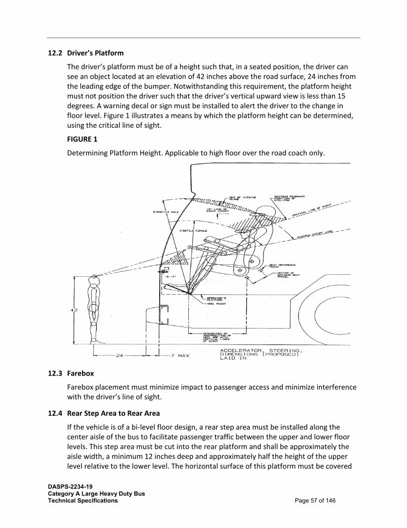
DASPS-2234-19 Category A Large Heavy Duty Bus Technical Specifications Page 57 of 146
12.2 Driver’s Platform
The driver’s platform must be of a height such that, in a seated position, the driver can see an object located at an elevation of 42 inches above the road surface, 24 inches from the leading edge of the bumper. Notwithstanding this requirement, the platform height must not position the driver such that the driver’s vertical upward view is less than 15 degrees. A warning decal or sign must be installed to alert the driver to the change in floor level. Figure 1 illustrates a means by which the platform height can be determined, using the critical line of sight.
FIGURE 1
Determining Platform Height. Applicable to high floor over the road coach only.
12.3 Farebox
Farebox placement must minimize impact to passenger access and minimize interference with the driver’s line of sight.
12.4 Rear Step Area to Rear Area
If the vehicle is of a bi-level floor design, a rear step area must be installed along the center aisle of the bus to facilitate passenger traffic between the upper and lower floor levels. This step area must be cut into the rear platform and shall be approximately the aisle width, a minimum 12 inches deep and approximately half the height of the upper level relative to the lower level. The horizontal surface of this platform must be covered
DASPS-2234-19 Category A Large Heavy Duty Bus Technical Specifications Page 58 of 146
with skid-resistant material with a visually contrasting nosing and must be sloped slightly for drainage. A warning decal or sign must be installed at the immediate platform area to alert passengers to the change in floor level.
13 WHEEL HOUSING
13.1 Design and Construction
Sufficient clearance and air circulation must be installed around the tires, wheels and brakes to preclude overheating when the bus is operating on the design operating profile.
Wheel housings must be constructed of corrosion-resistant and fire-resistant material.
13.2 Design and Construction (Transit Coach)
Interference between the tires and any portion of the bus must not be possible in maneuvers up to the limit of tire adhesion with weights from curb weight to GVWR. Wheel housings must be adequately reinforced where seat pedestals are installed. Wheel housings must have sufficient sound insulation to minimize tire and road noise and meet all noise requirements of this specification.
Design and construction of front wheel housings must allow for the installation of a radio or electronic equipment storage compartment on the interior top surface, or its use as a luggage rack.
The finish of the front wheel housings must be scratch-resistant and complement interior finishes of the bus to minimize the visual impact of the wheel housing. If fiberglass wheel housings are installed, then they must match interior finishes. The lower portion extending to approximately 10 to 12 in. above floor must be equipped with scuff-resistant coating or stainless steel trim.
Wheel housings, as installed and trimmed, must withstand impacts of a 2 in. steel ball with at least 200 ftlbs of energy without penetration.
Wheel housings not equipped with seats or equipment enclosure must have a horizontal assist mounted on the top portion of the housing no more than 4 in. higher than the wheel well housing.
14 CHASSIS
14.1 Suspension - General Requirements
The front, rear suspensions must be pneumatic type. The basic suspension system must last the service life of the bus without major overhaul or replacement. Adjustment points must be minimized and must not be subject to a loss of adjustment in service. Routine adjustments must be easily accomplished by limiting the removal or disconnecting the components.

DASPS-2234-19 Category A Large Heavy Duty Bus Technical Specifications Page 59 of 146
14.2 Alignment
All axles must be properly aligned so the vehicle tracks accurately within the size and geometry of the vehicle. Alignment must be performed after build and prior to delivery. A computerized alignment printout must be supplied with the vehicle.
14.3 Springs and Shock Absorbers - Suspension Travel
The suspension system must permit a minimum wheel travel of 2.75 inches jounce-upward travel of a wheel when the bus hits a bump (higher than street surface), and 2.75 inches rebound-downward travel when the bus comes off a bump and the wheels fall relative to the body. Elastomeric bumpers must be installed at the limit of jounce travel. Rebound travel may be limited by elastomeric bumpers or hydraulically within the shock absorbers. Suspensions must incorporate appropriate devices for automatic height control so that regardless of load the bus height relative to the centerline of the wheels does not change more than ½ inch at any point from the height required. The safe operation of a bus cannot be impacted by ride height up to 1 inch from design normal ride height.
14.4 Damping
Vertical damping of the suspension system must be accomplished by hydraulic shock absorbers mounted to the suspension arms or axles and attached to an appropriate location on the chassis. Damping must be sufficient to control coach motion to three cycles or less after hitting road perturbations. The shock absorber bushing must be made of elastomeric material that must last the life of the shock absorber. The damper must incorporate a secondary hydraulic rebound stop.
14.5 Lubrication - Standard Grease Fittings
All elements of steering, suspension and drive systems requiring scheduled lubrication must be installed with grease fittings conforming to SAE Standard J534. These fittings must be located for ease of inspection and must be accessible with a standard grease gun from a pit or with the bus on a hoist. Each element requiring lubrication must have its own grease fitting with a relief path. The lubricant specified must be standard for all elements on the bus serviced by standard fittings and must be required no less than every 6,000 miles.
14.6 Kneeling
A kneeling system must lower the entrance(s) of the bus a minimum of 2.5 in. during loading or unloading operations regardless of load up to GVWR, measured at the longitudinal centerline of the entrance door(s) by the driver. The kneeling control must provide the following functions:
• Downward control must be held to allow downward kneeling movement. • Release of the control during downward movement must completely stop the lowering
motion and hold the height of the bus at that position.

DASPS-2234-19 Category A Large Heavy Duty Bus Technical Specifications Page 60 of 146
• Upward control actuation must allow the bus to return to normal floor height without the driver having to hold the control.
The brake and throttle interlock must prevent movement when the bus is kneeled. The kneeling control must be disabled when the bus is in motion. The bus must kneel at a maximum rate of 1.25 in. per second at essentially a constant rate. After kneeling, the bus must rise within 3 seconds to a height permitting the bus to resume service and must rise to the correct operating height within 7 seconds regardless of load up to GVWR. During the lowering and raising operation, the maximum vertical acceleration must not exceed 0.2g, and the jerk must not exceed 0.3g/second.
An indicator visible to the driver must be illuminated until the bus is raised to a height adequate for safe street travel. An audible warning alarm must sound simultaneously with the operation of the kneeler to alert passengers and bystanders. A warning light mounted near the curbside of the front door, a minimum 2.5 in. diameter amber lens, must be provided that must blink when the kneel feature is activated. Kneeling must not be operational while the wheelchair ramp is deployed or in operation.
15 WHEELS AND TIRES
15.1 Wheels
All wheels must be interchangeable and must be removable without a puller. Wheels must be compatible with tires in size and load-carrying capacity. Front wheels and tires must be balanced as an assembly per SAE J1986.
15.2 Painted Steel
Wheels and rims must be hub-piloted steel with white powder coat (maximum 3.5 mil) and must resist rim flange wear. Aluminum wheels may be offered separately as an option.
Electric bus tires rims must be aluminum as standard.
15.3 Tires
Tires must be suitable for the conditions of transit service and sustained operation at the maximum speed capability of the bus. Load on any tire at GVWR must not exceed the tire Supplier’s rating.
15.4 Steering
Hydraulically assisted steering must be installed. The steering gear must be an integral type with the number and length of flexible lines minimized or eliminated. Engine driven hydraulic pump must be installed for power steering.
Electrically assisted steering must be installed as an option to reduce steering effort. An option for using TranSynd in the power steering pump and system may be made

DASPS-2234-19 Category A Large Heavy Duty Bus Technical Specifications Page 61 of 146
available. A remote mounted fluid sampling port, for the KP Series Pushbutton Sampling Valve or similar, must be installed for the hydraulic system.
15.5 Steering Axle Transit Coach - Solid Beam or Independent suspension type Axle and Grease-Type Front Bearings and Seals
The front axle must be solid beam, non-driving with a load rating sufficient for the bus loaded to GVWR and must be equipped with grease type front wheel bearings and seals.
All friction points on the front axle must be equipped with replaceable bushings or inserts and lubrication fittings easily accessible from a pit or hoist.
15.6 Steering and Tag Axles Commuter Coach
The front and tag axles must be a solid beam or independent suspension, non-driving with a load rating sufficient for the bus loaded to GVWR and must be equipped with unitized grease type wheel bearings and seals.
All friction points on the front axle must be equipped with replaceable bushings or inserts and, if needed, lubrication fittings easily accessible from a pit or hoist.
The steering geometry of the outside (frontlock) wheel must be within 2 degrees of true Ackerman up to 50 percent lock measured at the inside (backlock) wheel. The steering geometry must be within 3 degrees of true Ackerman for the remaining 100 percent lock measured at the inside (backlock) wheel.
15.7 Steering Wheel - Turning Effort
Steering effort must be measured with the bus at GVWR, stopped with the brakes released and the engine at normal idling speed on clean, dry, level, commercial asphalt pavement and the tires inflated to recommended pressure.
Under these conditions, the torque required to turn the steering wheel 10 degrees must be no less than 5 ft-lbs. and no more than 10 ft-lbs. Steering torque may increase to 70 ft-lbs. when the wheels are approaching the steering stops, as the relief valve activates.
Power steering failure must not result in loss of steering control. With the bus in operation, the steering effort must not exceed 55 pounds at the steering wheel rim, and perceived free play in the steering system must not materially increase as a result of power assist failure. Gearing must require no more than seven turns of the steering wheel lock-to-lock.
Caster angle must be selected to provide a tendency for the return of the front wheels to the straight position with minimal assistance from the driver.
15.8 Steering Wheel - General
The steering wheel diameter must be approximately 18-20 in.; the rim diameter must be ⅞ in. to 1¼ in. and shaped for firm grip with comfort for long periods of time.

DASPS-2234-19 Category A Large Heavy Duty Bus Technical Specifications Page 62 of 146
Steering wheel spokes and wheel thickness must ensure visibility of the dashboard so that vital instrumentation is clearly visible at center neutral position (within the range of a 95th-percentile male, as described in SAE 1050a, Sections 4.2.2 and 4.2.3). Placement of steering column must be as far forward as possible, but either in line with or behind the instrument cluster. The steering wheel must be telescoping and must have two separate tilt locations, one near the top of the column and one at the universal joint below the floor where the column is connected to the right angle steering box; tilt and telescope are controlled by levers on the left side of the column.
15.9 Steering Column - Tilt
The steering column must have full tilt capability with an adjustment range of no less than 40 degrees from the vertical and easily adjustable by the driver.
15.10 Steering Wheel - Telescopic Adjustment
The steering wheel must have full telescoping capability and have a minimum telescopic range of 2 in. and a minimum low-end adjustment of 29 in., measured from the top of the steering wheel rim in the horizontal position to the cab floor at the heel point.
TABLE 5
Steering Wheel Height1 Relative to Angle of Slope
At Minimum Telescopic Height Adjustment (29 in.)
At Maximum Telescopic Height Adjustment (5 in.)
Angle of Slope Height Angle of Slope Height
0 degrees 29 in. 0 degrees 34 in
15 degrees 26.2 in 15 degrees 31.2 in
25 degrees 24.6 in 25 degrees 29.6 in
35 degrees 22.5 in 35 degrees 27.5 in
1. Measured from bottom portion closest to driver.
16 Drive Axle The bus must be driven by a heavy-duty axle with a load rating sufficient for the bus loaded to GVWR. The drive axle must have a design life to operate for not less than 300,000 miles on the design operating profile without replacement or major repairs. The lubricant drain plug must be magnetic type. If a planetary and/or reduction gear design is employed, the oil level in the planetary gears must be easily checked through the plug or

DASPS-2234-19 Category A Large Heavy Duty Bus Technical Specifications Page 63 of 146
sight gauge. The axle and driveshaft components must be rated for both propulsion and retardation modes with respect to duty cycle.
NOTE: The retardation duty cycle can be more aggressive than propulsion. The drive shaft must be guarded to prevent hitting any critical systems, including brake lines, coach floor or the ground, in the event of a tube or universal joint failure.
16.1 Non-Drive Axle
The non-drive axle is the drive axle without the drive gear with a load rating sufficient for the load to GVWR.
16.2 Tag Axles (Commuter Coach)
A tag axle must be located behind the drive axle. The tag axle must be a solid beam type with fixed steering. The tag axle must have single tires the same size as the tires on the front and drive axles. Tag axle weight must not exceed 14,000 lbs. With full passenger seating capacity, load on any axle must not exceed 22,400 lbs. Combined load capacity weight on the drive and tag axles must not exceed 36,500 lbs. A tag axle unloading feature must allow full or partial unloading, or dumping of air from the tag axle air spring bellows. This feature enables weight to shift to the drive axle for more traction. Manual unloading valves are located inside the RH rear curbside service door.
16.3 Turning Radius
The bus must meet the standards for turning in the table below on a straight, level road at GVWR with all accessories operating. The Contractor must provide documentation for the turning radius of the bus when the bus has a 48 in. box bike rack attached to the front end.
Bus Length(approximate) Maximum Turning Radius
35 ft 39 ft
40 ft 44 ft
45 ft 49 ft

DASPS-2234-19 Category A Large Heavy Duty Bus Technical Specifications Page 64 of 146
17 BRAKES
17.1 Service Brake
Brakes must be self-adjusting. Brake wear indicators (visible brake sensors) must be installed on exposed push rods if applicable.
Visible stroke indicators may be combined with electronic brake monitoring system and vehicle brake warning system to notify driver and maintenance of unsafe brake conditions.
17.2 Air-Actuated Brakes
Service brakes must be controlled and actuated by a compressed air system. Force to activate the brake pedal control must be an essentially linear function of the bus deceleration rate and must not exceed 70 lbs at a point 7 in. above the heel point of the pedal to achieve maximum braking. The heel point is the location of the driver’s heel when his or her foot is rested flat on the pedal and the heel is touching the floor or heel pad of the pedal. The ECU for the ABS system must be protected, yet in an accessible location to allow for ease of service.
The total braking effort must be distributed between all wheels in such a ratio as to ensure equal friction material wear rate at all wheel locations. Manufacturer shall demonstrate compliance by providing a copy of a thermo dynamic brake balance test upon request.
17.3 Automatic Traction Control
Microprocessor controlled automatic traction control (ATC) must be installed.
17.4 Friction Material
The brake linings must be made of non-asbestos material. In order to aid maintenance personnel in determining extent of wear, a provision such as a scribe line or chamfer indicating the thickness at which replacement becomes necessary shall be installed on each brake lining. The complete brake lining wear indicator must be clearly visible from the hoist or pit without removing backing plates.
17.5 Hubs
Replaceable wheel bearing seals must run on replaceable wear surfaces or be of an integral wear surface sealed design. Wheel bearing and hub seals and unitized hub assemblies must not leak or weep lubricant when operating on the design operating profile for the duration of the initial manufacturer’s warranty or the life of the brake lining whichever is longer.

DASPS-2234-19 Category A Large Heavy Duty Bus Technical Specifications Page 65 of 146
17.6 Drum Brakes
Brake shoe return springs must be the heaviest available.
The service brakes must be two (2) shoe, internal-expanding, air operated S-cam type brakes at each wheel. The brakes must be capable of stopping the vehicle in accordance with the performance requirements of State and Federal regulations in effect at the time of manufacture. Parking brake must be spring applied, air released chamber mounted on the rear axle assembly. All brake linings must be of non-asbestos material three quarters (3/4) inch thick.
Spring brake chambers must be installed and must comply with requirements of State and Federal regulations FMVSS 121 in effect at time of manufacturer on the front and rear of these buses. At a minimum the front chamber must be size 24 to 30 inches and the rear must be size 30 to 36 inches depending on the length of the bus. The emergency air tank must be piped to a service valve at the left front corner of the bus to fill the tank for towing the vehicle. Brake shoe effective area must total a minimum of eight-hundred twenty-two (822) square inches for 30 to 35 foot buses and nine-hundred thirty-two (932) square inches for buses greater than 35 feet in length.
Brake shoes must be operated by cams which in return are operated by automatic slack adjusters. Slack adjusters must be equipped with grease fittings and be capable of automatic adjustments throughout the life of the lining and drum assembly. Brake lines must be installed so that the possibility of damage is minimized. Lines and hoses must be clamped and supported in a manner which minimizes long, unsupported hose lengths and precludes rubbing against any part of the bus.
The parking and emergency brakes must be with a 40 PSI setting, controlled by a manual valve located convenient to the driver for safe, convenient access. Valve operation must be "pull to set brakes" and "push to release" type brake system.
This brake must have stopping ability that is equal to or better than required by Federal and State regulations. It must automatically apply if air system pressure falls below half the normal value or such other value as is recommended by the manufacturer. This parking/emergency brake must be of spring brake design.
17.7 Disc Brakes on All Axles (optional)
The bus must be equipped with disc brakes on all axles, and the brake discs must allow machining of each side of the disc to obtain smooth surfaces per manufacturer’s specifications.
The brake system material and design must be selected to absorb and dissipate heat quickly so that the heat generated during braking operation does not glaze brake linings.
Typical brake drum/shoe set up may be made available as an option and included in options list.

DASPS-2234-19 Category A Large Heavy Duty Bus Technical Specifications Page 66 of 146
17.8 Hub and Drums Commuter Coach
Replaceable wheel bearing seals must run on replaceable wear surfaces or be of an integral wear surface sealed design. Wheel bearing and hub seals and unitized hub assemblies must not leak or weep lubricant when operating on the design operating profile for the duration of the initial manufacturer’s warranty.
The bus must be equipped with disc brakes on all axles, and the brake discs must allow machining of each side of the disc to obtain smooth surfaces per manufacturer’s specifications.
17.9 Parking/Emergency Brake
17.9.1 Air Brakes The parking brake must be a spring-operated system, actuated by a valve that exhausts compressed air to apply the brakes. The parking brake may be manually enabled when the air pressure is at the operating level per FMVSS 121.
17.9.2 Hydraulic Brakes If the bus is equipped with hydraulic brakes, then the braking system must comply with FMVSS 105, including both service and parking brake features.
18 INTERLOCKS
18.1 Passenger Door Interlocks
To prevent opening mid and rear passenger doors while the bus is in motion, a speed sensor must be integrated with the door controls to prevent the mid/rear doors from being enabled or opened unless the bus speed is less than 2 mph.
To preclude movement of the bus, an accelerator interlock must lock the accelerator in the closed position, and a brake interlock must engage the service brake system to stop movement of the bus when the driver’s door control is moved to a mid/rear door enable or open position, or a mid or rear door panel is opened more than 3 in. from the fully closed position (as measured at the leading edge of the door panel). The interlock engagement must bring the bus to a smooth stop and shall be capable of holding a fully loaded bus on a 6 percent grade, with the engine at idle and the transmission in gear, until the interlocks are released. These interlock functions must be active whenever the vehicle Master Run Switch is in any run position.
18.2 Requiring Accelerator Interlock Whenever Front Doors Are Open
Base bus must include an installed accelerator interlock that must lock the accelerator in the closed position, and a brake interlock must engage the service brake system to stop movement of the bus whenever front doors are open, selection to be made by Authorized Purchaser at pre-production meeting.

DASPS-2234-19 Category A Large Heavy Duty Bus Technical Specifications Page 67 of 146
18.3 Pneumatic System - General
The bus air system must operate the air-powered accessories and the braking system with reserve capacity. New buses must not leak down more than 5 psi over a 15-minute period of time as indicated on the dash gauge.
Provision must be made to apply shop air to the bus air systems. A quick disconnect fitting must be easily accessible and located in the engine compartment and near the front bumper area for towing. Fittings must be protected against dirt and moisture when not in use. Air for the compressor must be filtered. The air system must be protected per FMVSS 121.
18.4 Air Compressor
For diesel and hybrid buses, an engine-driven air compressor must be sized to charge the air system from 40 psi to the governor cutoff pressure in less than 4 minutes while not exceeding the fast-idle speed setting of the engine.
For electric bus, the electrically driven air compressor must be sized to charge the air system from 40 psi to the governor cutoff pressure in less than 4 minutes while not exceeding the fast-idle speed setting of the engine. The electrically driven air compressor may be available as an option for diesel and hybrid buses if available.
18.5 Air Lines and Fittings
Air lines, except necessary flexible lines, must conform to the installation and material requirements of SAE Standard J1149 for copper tubing with standard, brass, flared or ball sleeve fittings, or SAE Standard J844 for nylon tubing if not subject to temperatures over 200 °F. The air on the delivery side of the compressor where it enters nylon housing must not be above the maximum limits as stated in SAE J844. Nylon tubing must be installed in accordance with the following color-coding standards:
• Green: Indicates primary brakes and supply. • Red: Indicates secondary brakes. • Brown: Indicates parking brake • Yellow: Indicates compressor governor signal. • Black: Indicates accessories.
Contractor shall define any additional color coded tubing provided. Line supports must prevent movement, flexing, tension, strain and vibration. Copper lines must be supported to prevent the lines from touching one another or any component of the bus. To the extent practicable and before installation, the lines must be pre-bent on a fixture that prevents tube flattening or excessive local strain. Copper lines must be bent only once at any point, including pre-bending and installation. Rigid lines must be supported at no more than 5-ft intervals. Nylon lines may be grouped and must be supported at 30 34in. intervals or less.
The compressor discharge line between powerplant and body-mounted equipment must be flexible convoluted copper or stainless-steel line, or may be flexible Teflon hose with a

DASPS-2234-19 Category A Large Heavy Duty Bus Technical Specifications Page 68 of 146
braided stainless steel jacket. Other lines necessary to maintain system reliability must be flexible Teflon hose with a braided stainless-steel jacket. End fittings must be standard SAE or JIC brass or steel, flanged, swivel-type fittings. Flexible hoses must be as short as practicable and individually supported. They must not touch one another or any part of the bus except for the supporting grommets. Flexible lines must be supported at 2- 2.5 ft intervals or less.
Air lines must be clean before installation and must be installed to minimize air leaks. All air lines must be routed to prevent water traps to the extent possible. Grommets or insulated clamps must protect the air lines at all points where they pass through understructure components. All air lines must be installed and routed in such a way as to eliminate any chance for water buildup in the lines.
18.6 Air Reservoirs
All air reservoirs must meet the requirements of FMVSS Standard 121 and SAE Standard J10 and must be equipped with drain plugs and guarded or flush type drain valves. Major structural members must protect these valves and any automatic moisture ejector valves from road hazards. Reservoirs must be sloped toward the drain valve. All air reservoirs must have drain valves that discharge below floor level with lines routed to eliminate the possibility of water traps and/or freezing in the drain line. All air tanks and drain valves must be clearly labeled.
18.7 Air System Dryer
An air dryer must prevent accumulation of moisture and oil in the air system. The air dryer system must include one or more replaceable desiccant cartridges.
The air system must be equipped with an air dryer located before the no. 1 air tank and as far from the compressor as possible to allow air to cool prior to entering the air dryer.

DASPS-2234-19 Category A Large Heavy Duty Bus Technical Specifications Page 69 of 146
19 ELECTRICAL, ELECTRONIC AND DATA COMMUNICATION SYSTEMS
19.1 Overview
The electrical system must consist of vehicle battery systems and components that generate, distribute and store power throughout the vehicle. (e.g., generator, voltage regulator, wiring, relays, and connectors). Electronic devices are individual systems and components that process and store data, integrate electronic information or perform other specific functions.
The data communication system consists of the bi-directional communications networks that electronic devices use to share data with other electronic devices and systems. Communication networks are essential to integrating electronic functions, both onboard the vehicle and off.
Information level systems that require vehicle information for their operations or provide information must adhere to J1939 data standard.
Data communications systems are divided into three levels to reflect the use of multiple data networks:
• Drivetrain level: Components related to the drivetrain including the propulsion system components (engine, transmission and hybrid units or electric energy storage, motors, inverters/converters), and anti-lock braking system (ABS), which may include traction control.
• Information level: Components whose primary function is the collection, control or display of data that is not necessary to the safe drivability of the vehicle (i.e., the vehicle will continue to operate when those functions are inoperable). These components typically consist of those required for automatic vehicle location (AVL) systems, destination signs, fare boxes, passenger counters, radio systems, automated voice and signage systems, video surveillance and similar components.
• Multiplex level: Electrical or electronic devices controlled through input/output signals such as discrete, analog and serial data information (i.e., on/off switch inputs, relay or relay control outputs). Multiplexing is used to control components not typically found on the drivetrain or information levels, such as lights; wheelchair lifts; doors; heating, ventilation and air conditioning (HVAC) systems; and gateway devices.
FIGURE 2
Data Communications Systems Levels
Information level
Multiplex level
Drivetrain level

DASPS-2234-19 Category A Large Heavy Duty Bus Technical Specifications Page 70 of 146
19.2 Modular Design
Design of the electrical, electronic and data communication systems must be modular so that each electronic device, apparatus panel, or wiring bundle is easily separable from its interconnect by means of connectors.
Powerplant wiring must be an independent wiring harness. Replacement of the engine compartment wiring harness(es) must not require pulling wires through any bulkhead or removing any terminals from the wires.
19.3 Environmental and Mounting Requirements
The electrical system and its electronic components must be capable of operating in the area of the vehicle in which they will be installed, as recommended in SAE J1455.
Electrical and electronic equipment must not be located in an environment that will reduce the performance or shorten the life of the component or electrical system when operating within the design operating profile. As a recommendation, no vehicle component must generate, or be affected by, electromagnetic interference or radio frequency interference (EMI/RFI) that can disturb the performance of electrical/electronic equipment as defined in SAE J1113 and UNECE Council Directive 95/54 (R 10).
The Authorized Purchaser must follow recommendations from bus manufacturers and subsystem Suppliers regarding methods to prevent damage from voltage spikes generated from welding, jump starts, shorts, etc.
All electrical/electronic hardware mounted in the interior of the vehicle must be inaccessible to passengers and hidden from view unless intended to be viewed. The hardware must be mounted in such a manner as to protect it from splash or spray.
All electrical/electronic hardware mounted on the exterior of the vehicle, that is not designed to be installed in an exposed environment, must be mounted in a sealed enclosure.
All electrical/electronic hardware and its mounting must comply with the shock and vibration requirements of SAE J1455.
The voltage regulator must be a solid-state type coordinated with and adjusted for the alternator and batteries used. The regulator must be remotely mounted and be easily accessible for maintenance purposes. The battery tray must be stainless steel or supported by a stainless steel sub-frame. The stainless-steel battery tray and slide must be protected against the accumulation of debris and road spray. The battery tray must slide out, on stainless steel rollers, with less than 50 lbs. of effort.
The battery tray must have drain holes. Two twelve volt lead acid filled thermal battery units, size 8D, with side post connectors with minimum 1300 cold cranking amps at zero

DASPS-2234-19 Category A Large Heavy Duty Bus Technical Specifications Page 71 of 146
degrees Fahrenheit with a reserve capacity of 425 minutes or greater will be required, except for electric buses which must be supplied with at minimum two group AGM Group 31 batteries each with a minimum of 1150 cold cranking amps. Protective interlocks or programming must be installed so the starter will not operate if the engine is running or the transmission is not in neutral. Electrical cables and wiring must be adequate for all anticipated loads. The main wiring harness must, to the maximum extent practical, be installed inside the bus body passenger compartment and, where that is not practical, must be secured in frame rail raceways. The Contractor must route and secure all wiring so that it does not rub anywhere. Routing of step well light wiring must be such as to avoid rubbing door posts, etc. When wires or looms pass through metal, the wires must be protected by a rubber grommet. Each electrical panel i.e. front and exit door panels, battery compartment, and front electrical panel must provide an explanation of the respective electrical circuits and components contained within and must be furnished in a silk-screened or water/oil proof diagram on the inside of the door panel.
Four AGM batteries or equivalent may be an option in lieu of two size 8D batteries.
All engine compartment wiring and light wiring must be insulated from the heat and be resistant to oil and grease. Electrical equipment, junction boxes and connectors must not be placed where they are subjected to excessive heat, oil, grease, or road spray. All multiple terminal connectors must be military (cannon plug) type or equivalent, fully sealed and protected to prevent outside dirt and corrosives from entering the wiring, connectors, or plugs.
All main power supply terminals must be covered with electric post rubber cover. All electrical end plugs must be covered. Unless the wiring harness can be serviced as a complete unit, wiring harnesses must incorporate 10% spare wires. Wiring located in the engine compartment must be routed away from high-heat sources or shielded and/or insulated from temperatures exceeding the wiring and connector operating requirements. All cables and harnesses must be secured to prevent chafing or shorting against each other or any part of the vehicle. Clamps must meet or exceed aircraft type be rubber or PVC clad. Grommets or other protective material must be installed at points where wiring penetrates metal structures.
Unless approved otherwise, all wiring must start and end at a junction block or component. All inline and bulkhead connectors are to be of the weather pack sealed type.
Multi-pin connectors must be protected internally from corrosion with silicone dielectric grease (Dow Corning #4), if required. All circuits except the engine emergency shut-off and speedometer circuits must be protected by reset circuit breakers that clearly indicate their position when tripped. Each breaker must be labeled. Circuit breakers must have plastic dust caps or be placed in a sealed enclosure. Provide constant power for powering systems, as requested by Agency, such as but not limited to the fire suppression, radio, farebox, and DC-DC converter that require constant power when battery cutoff switch is off.

DASPS-2234-19 Category A Large Heavy Duty Bus Technical Specifications Page 72 of 146
The vehicle must be equipped with a 12VDC and 24VDC quick disconnect switch. The battery compartment door must conveniently accommodate operation of the 12VDC and 24VDC quick disconnect switch.
The battery switch access door must not require any special locking devices to gain access to the switch, and it must be accessible without removing or lifting the panel. The door must be flush-fitting and incorporate a spring tensioner or equal to retain the door in a closed position when not in use.
Remote (divorce) mount alternator voltage regulator must meet or exceed A2-377 with jumper cable and 5 amp fuse must be installed. This requirement does not apply to battery electric buses.
The windshield wiper and headlamps electric circuit must be protected by modified circuit breakers sized to the requirement of the load or run through the multiplex - programmable logic controller (PLC), and are fuse protected.
Rubber Covers must be provided for all the Electric Posts that may be exposed to a corrosive environment.
All junction boxes located in the engine compartment must be designed to allow thorough steam cleaning of the engine compartment area without intrusion of water.
An optional voltage spike arrestor, S.K.I. Products SKI241-101445, or approved equal, must be provided in the main power circuit and be included with options list.
Major junction panels must be readily accessible for maintenance, not located behind or alongside seat or other fixed/semi-fixed obstructions. Exterior access panels and junction box covers must have seals which will preclude entry of rain, wash water, road debris, etc. All wiring and junction panel terminals must be coded for easy identification. A diagram showing the coding as the bus was built must be furnished.
The Contractor shall supply at least two spare circuits in the main harness between the front and rear of the bus. The main harness from the engine compartment must be equipped with multiple circuit cannon type connectors.
19.4 Hardware Mounting
The mounting of the hardware must not be used to provide the sole source ground, and all hardware must be isolated from potential EMI/RFI, as referenced in SAE J1113.
All electrical/electronic hardware mounted in the interior of the vehicle must be inaccessible to passengers and hidden from view unless intended to be viewed. The hardware must be mounted in such a manner as to protect it from splash or spray.
All electrical/electronic hardware mounted on the exterior of the vehicle that is not designed to be installed in an exposed environment must be mounted in a sealed enclosure.
All electrical/electronic hardware and its mounting must comply with the shock and vibration requirements of SAE J1455.

DASPS-2234-19 Category A Large Heavy Duty Bus Technical Specifications Page 73 of 146
20 GENERAL ELECTRICAL REQUIREMENTS BATTERIES
20.1 Low-Voltage Batteries (24V)
20.2 Two 8D Battery Units
Two 8D battery units with side post connectors, conforming to SAE Standard J537, must be installed. Each battery must have a minimum of 1300 cold cranking amps. Each battery shall have a purchase date no more than 120 days from the date of release and shall be fully maintained prior to shipment to the Authorized Purchaser. The battery compartment must be well-ventilated to prevent hydrogen buildup while protecting the compartment from road spray, water intrusion and de-icing chemicals.
Hybrid Electric buses that do not utilize the 24V coach batteries to crank the diesel engine may disregard the Cold Cranking Amp requirement and provide batteries as follows:
A minimum of 2 AGM type Group 31 batteries with a total of N Amp-hours capacity. The batteries must be of a type that is rated for deep cycle use.
The N will be calculated as follow:
The N will probably have to vary from agency to agency unless they would like to take the worst-case maximum and specify that number as the common requirement.
N is calculated as follows:
1) Determine the total current draw (A) for all equipment that remains powered up when the bus is turned off – Radio systems, fare-box alarms, camera systems, Fire suppression systems, etc., etc.
2) Determine the longest time interval that a bus will remain off on a regularly scheduled basis (H) - (eg. – from Friday at midnight until Monday at 5 am – 53 hours).
3) Finally, plan for a maximum battery discharge of 80% to allow some charge for system startup on Monday morning and allow for end-of-life capacity degradation. So the formula is: A × H ÷ 80%.
For Example: Total “always on” current draw = 3 amps Maximum routine bus-off time = 53 hours Amp-Hour Requirement = 3 × 53 ÷ 0.8 = 198.75 or ≈ 200 Amp-hours
To be more conservative and allow for other factors, such as unanticipated current drain, cold weather conditions and others they could plan on 75% of usable capacity rather than 80%
20.3 Battery Cables
The battery terminal ends and cables must be color-coded with red for the primary positive, black for negative and another color for any intermediate voltage cables.

DASPS-2234-19 Category A Large Heavy Duty Bus Technical Specifications Page 74 of 146
Positive and negative battery cables must not cross each other if at all possible, be flexible and sufficiently long to reach the batteries with the tray in the extended position without stretching or pulling on any connection and must not lie directly on top of the batteries. Battery and starter wiring must be continuous cables with connections secured by bolted terminals and must conform to specification requirements of SAE Standards.
2100 strand 4/0 cable or greater recommended.
20.4 Jump-Start Connector
A jump-start connector, red for 24V and blue for 12V, whichever is applicable, must be provided at a location determined at the pre-production meeting and must be equipped with dust cap and adequately protected from moisture, dirt and debris.
20.5 Battery Compartment
The battery compartment must prevent accumulation of snow, ice and debris on top of the batteries and must be vented and self-draining. It must be accessible only from the outside of the vehicle. All components within the battery compartment, and the compartment itself, must be protected from damage or corrosion from the electrolyte. The inside surface of the battery compartment’s access door must be electrically insulated, as required, to prevent the battery terminals from shorting on the door if the door is damaged in an accident or if a battery comes loose.
The vehicle must be equipped with a 12VDC and 24VDC quick disconnect switch(es). The battery compartment door must conveniently accommodate operation of the 12VDC and 24VDC quick disconnect switch(es).
The battery quick disconnect access door must be identified with a decal. The decal size must not be less than 3.5 × 5 in. (8.89 × 12.7 cm).
The battery hold-down bracket must be constructed of a non-metallic material (plastic or fiberglass).
This access door must not require any special locking devices to gain access to the switch, and it must be accessible without removing or lifting the panel. The door must be flush-fitting and incorporate a spring tensioner or equal to retain the door in a closed position when not in use. The batteries must be securely mounted on a stainless steel, or equivalent tray that can accommodate the size and weight of the batteries. The battery tray must pull out easily and properly support the batteries while they are being serviced. The tray must allow each battery cell to be easily serviced and filled. A locking device must retain the battery tray to the stowed position.
Polyethylene battery tray and enclosure may be included with options list.
If not located in the engine compartment, the same fire-resistant properties must apply to the battery compartment. No sparking devices must be located within the battery box.

DASPS-2234-19 Category A Large Heavy Duty Bus Technical Specifications Page 75 of 146
20.6 Auxiliary Electronic Power Supply
If required, gel-pack, or any form of sealed (non-venting) batteries used for auxiliary power are allowed to be mounted on the interior of the vehicle if they are contained in an enclosed, non-airtight compartment and accessible only to maintenance personnel. This compartment must contain a warning label prohibiting the use of lead-acid batteries.
20.7 Master Battery Switch
A single master switch must be installed near the battery compartment for the disconnecting of all battery positives (12V and 24V), except for safety devices such as the fire suppression system and other systems as specified. The location of the master battery switch must be clearly identified on the exterior access panel, be accessible in less than 10 seconds for deactivation and prevent corrosion from fumes and battery acid when the batteries are washed off or are in normal service. The access door must be labeled "Battery Emergency Shut-Off Switch." A 12V power supply with cover must be provided in the driver’s area.
Turning the master switch off with the powerplant operating must shut off the engine and must not damage any component of the electrical system. The master switch must be capable of carrying and interrupting the total circuit load.
20.8 Single Switch
The batteries must be equipped with a single switch for disconnecting both 12V and 24V power.
20.9 Low-Voltage Generation and Distribution
The low-voltage generating system must maintain the charge on fully charged batteries, except when the vehicle is at standard idle with a total low voltage generator load exceeding 70 percent of the low voltage generator nameplate rating. A low voltage generating system must be a solid-state DC/DC converter for Battery Electric and Hybrid-Electric buses.
Voltage monitoring and over-voltage output protection (recommended at 32V) must be provided. Dedicated power and ground must be provided as specified by the component or system manufacturer. Cabling to the equipment must be sized to supply the current requirements with no greater than a 5 percent volt drop across the length of the cable.
An optional 24 volt to 13.6 volt DC-DC converter, 30 ampere output, Model 1645-24-12-30, manufactured by Wilmore Electronics Co., Inc. or equivalent may be included with options list. The unit must be located in the communications equipment box and must provide power to a terminal block for the Radio, VLU, DR600 stop announcement system, CCTV system, fare-box, and destination sign.
An optional 110 volt inverter must be supplied that allows the interior dome lights to operate when connected to a 110 volt outlet, even with all other bus systems “asleep”. This system must include an external weatherproof port that a regular 110 volt extension

DASPS-2234-19 Category A Large Heavy Duty Bus Technical Specifications Page 76 of 146
cord can be connected to. Consideration should be given to other loads that could be included in this system such as a laptop charger or vacuum cleaner.
20.10 Circuit Protection
All branch circuits, except battery-to-starting motor and battery-to-generator/alternator circuits, must be protected by current-limiting devices such as circuit breakers, fuses or solid-state devices sized to the requirements of the circuit. Electronic circuit protection for the cranking motor must be installed to prevent engaging of the motor for more than 30 seconds at a time to prevent overheating. The circuit breakers or fuses must be easily accessible for authorized personnel. Fuses must be used only where it can be demonstrated that circuit breakers are not practicable. This requirement applies to in-line fuses supplied by either the Contractor or a Supplier. Fuse holders must be constructed to be rugged and waterproof. All manual reset circuit breakers critical to the operation of the bus must be mounted in a location convenient to the Authorized Purchaser mechanic with visible indication of open circuits. The Authorized Purchaser will consider the application of automatic reset circuit breakers on a case-by-case basis. The Contractor shall show all in-line fuses in the final harness drawings. All manually resettable circuit breakers must provide a visible indication of open circuits.
Circuit breakers or fuses must be sized to a minimum of 15 percent larger than the total circuit load. The current rating for the wire used for each circuit must exceed the size of the circuit protection being used.
20.11 Grounds
The battery must be grounded to the vehicle chassis/frame at one location only, as close to the batteries as possible. When using a chassis ground system, the chassis must be grounded to the frame in multiple locations, evenly distributed throughout the vehicle to eliminate ground loops. No more than four ground ring/spade terminal connections must be made per ground stud. Electronic equipment requiring an isolated ground to the battery (i.e., electronic ground) must not be grounded through the chassis.
20.12 Low Voltage/Low Current Wiring and Terminals
All power and ground wiring must conform to specification requirements of SAE Recommended Practice J1127, J1128 and J1292. Double insulation must be maintained as close to the junction box, electrical compartment or terminals as possible. The requirement for double insulation must be met by wrapping the harness with plastic electrical tape or by sheathing all wires and harnesses with non-conductive, rigid or flexible conduit.
Wiring must be grouped, numbered and/or color-coded. Wiring harnesses must not contain wires of different voltage classes unless all wires within the harness are insulated for the highest voltage present in the harness. Kinking, grounding at multiple points, stretching, and exceeding minimum bend radius must be prevented.

DASPS-2234-19 Category A Large Heavy Duty Bus Technical Specifications Page 77 of 146
Strain-relief fittings must be installed at all points where wiring enters electrical compartments. Grommets or other protective material must be installed at points where wiring penetrates metal structures outside of electrical enclosures. Wiring supports must be protective and non-conductive at areas of wire contact and must not be damaged by heat, water, solvents or chafing.
To the extent practicable, wiring must not be located in environmentally exposed locations under the vehicle. Wiring and electrical equipment necessarily located under the vehicle must be insulated from water, heat, corrosion and mechanical damage. Where feasible, front to rear electrical harnesses must be installed above the window line of the vehicle. If harness is not able to be serviced as a complete unit, All wiring harnesses over 5 ft long and containing at least five wires must include 10 percent (minimum one wire) excess wires for spares. This requirement for spare wires does not apply to data links and communication cables. Wiring harness length must allow end terminals to be replaced twice without pulling, stretching or replacing the wire. Terminals must be crimped to the wiring according to the connector manufacturer’s recommendations for techniques and tools. All cable connectors must be locking type, keyed and sealed, unless enclosed in watertight cabinets or vehicle interior. Pins must be removable, crimp contact type, of the correct size and rating for the wire being terminated. Unused pin positions must be sealed with sealing plugs. Adjacent connectors must either use different inserts, different insert orientations, or be labeled to prevent incorrect connections.
Terminals must be crimped, corrosion-resistant and full ring type or interlocking lugs with insulating ferrules. When using pressure type screw terminal strips, only stranded wire must be used. Insulation clearance must ensure that wires have a minimum of “visible clearance” and a maximum of two times the conductor diameter or 1/16 in., whichever is less. When using shielded or coaxial cable, upon stripping of the insulation, the metallic braid must be free from frayed strands that can penetrate the insulation of the inner wires.
Ultra-sonic and T-splices may be used with 7 AWG or smaller wire. When a T-splice is used, it must meet these additional requirements:
• It must include a mechanical clamp in addition to solder on the splice. • The wire must support no mechanical load in the area of the splice. • The wire must be supported to prevent flexing.
All splicing must be staggered in the harness so that no two splices are positioned in the same location within the harness.
Wiring located in the engine compartment must be routed away from high-heat sources or shielded and/or insulated from temperatures exceeding the wiring and connector operating requirements.
The instrument panel and wiring must be easily accessible for service from the driver’s seat or top of the panel. The instrument panel must be separately removable and
DASPS-2234-19 Category A Large Heavy Duty Bus Technical Specifications Page 78 of 146
replaceable without damaging the instrument panel or gauges. Wiring must have sufficient length and be routed to permit service without stretching or chafing the wires.
20.13 Electrical Components
All electrical components, including switches, relays, flashers and circuit breakers, must be heavy-duty designs with either a successful history of application in heavy-duty vehicles or design specifications for an equivalent environment.
All electric motors must be heavy-duty brushless type where practical and have a continuous duty rating of no less than 25,000 hours (except cranking motors, washer pumps and wiper motors). All electric motors must be easily accessible for servicing.
20.14 Electrical Compartments
All relays, controllers, flashers, circuit breakers and other electrical components must be mounted in easily accessible electrical compartments. All compartments exposed to the outside environment must be corrosion-resistant and sealed. The components and their functions in each electrical compartment must be identified and their location permanently recorded on a drawing attached to the inside of the access panel or door. The drawing must be protected from oil, grease, fuel and abrasion.
The front compartment must be completely serviceable from the driver’s seat, vestibule or from the outside if applicable. “Rear start and run” controls must be mounted in an accessible location in the engine compartment and must be protected from the environment.
20.15 General Electronic Requirements
If an electronic component has an internal real-time clock, it must provide its own battery backup to monitor time when battery power is disconnected, and/or it may be updated by a network component. If an electronic component has an hour meter, it must record accumulated service time without relying on battery backup.
All electronic component Suppliers shall ensure that their equipment is self-protecting in the event of shorts in the cabling, and also in over-voltage (over 32V DC on a 24V DC nominal voltage rating with a maximum of 50V DC) and reverse polarity conditions. If an electronic component is required to interface with other components, it shall not require external pull-up and/or pull-down resistors. Where this is not possible, the use of a pull-up or pull-down resistor shall be limited as much as possible and easily accessible and labeled.
20.16 Wiring and Terminals
Kinking, grounding at multiple points, stretching and reducing the bend radius below the manufacturer’s recommended minimum must not be permitted.

DASPS-2234-19 Category A Large Heavy Duty Bus Technical Specifications Page 79 of 146
20.17 Discrete I/O (Inputs/Outputs)
All wiring to I/O devices, either at the harness level or individual wires, must be labeled, stamped or color-coded in a fashion that allows unique identification at a spacing not exceeding 4 in. Wiring for each I/O device must be bundled together. If the I/O terminals are the same voltages, then jumpers may be used to connect the common nodes of each I/O terminal.
20.18 Shielding
All wiring that requires shielding must meet the following minimum requirements. A shield must be generated by connecting to a ground, which is sourced from a power distribution bus bar or chassis. A shield must be connected at one location only, typically at one end of the cable. However certain standards or special requirements, such as SAE J1939 or RF applications, have separate shielding techniques that also must be used as applicable.
NOTE: A shield grounded at both end forms a ground loop, which can cause intermittent control or faults.
When using shielded or coaxial cable, upon stripping of the insulation, the metallic braid must be free from frayed strands, which can penetrate the insulation of the inner wires. To prevent the introduction of noise, the shield must not be connected to the common side of a logic circuit.
20.19 Communications
The data network cabling must be selected and installed according to the selected protocol requirements. The physical layer of all network communication systems must not be used for any purpose other than communication between the system components, unless provided for in the network specifications.
Communications networks that use power line carriers (e.g., data modulated on a 24V-power line) must meet the most stringent applicable wiring and terminal specifications.
20.20 Radio Frequency (RF)
RF components, such as radios, video devices, cameras, global positioning systems (GPS), etc., must use coaxial cable to carry the signal. All RF systems require special design consideration for losses along the cable. Connectors must be minimized, since each connector and crimp has a loss that will attribute to attenuation of the signal. Cabling must allow for the removal of antennas or attached electronics without removing the installed cable between them. If this cannot be done, then a conduit of sufficient size must be provided for ease of attachment of antenna and cable assembly. The corresponding component vendors must be consulted for proper application of equipment, including installation of cables.

DASPS-2234-19 Category A Large Heavy Duty Bus Technical Specifications Page 80 of 146
20.21 Audio
Cabling used for microphone level and line level signals must be 22 AWG minimum with shielded twisted pair. Cabling used for amplifier level signals must be 18 AWG minimum.

DASPS-2234-19 Category A Large Heavy Duty Bus Technical Specifications Page 81 of 146
21 MULTIPLEXING
21.1 General
The primary purpose of the multiplexing system is control of components necessary to operate the vehicle. This is accomplished by processing information from input devices and controlling output devices through the use of an internal logic program.
Versatility and future expansion must be provided for by expandable system architecture. The multiplex system must be capable of accepting new inputs and outputs through the addition of new modules and/or the utilization of existing spare inputs and outputs. All like components in the multiplex system must be modular and interchangeable with self-diagnostic capabilities. The modules must be easily accessible for troubleshooting electrical failures and performing system maintenance. Multiplex input/output modules must use solid-state devices to provide extended service life and individual circuit protection. Ten percent of the total number of inputs and outputs, or at least one each for each voltage type utilized (0V, 12V, 24V), at each module location must be designated as spares.
21.2 System Configuration
Multiplexing may either be distributed or centralized. A distributed system must process information on multiple control modules within the network. A centralized system must process the information on a single control module. Either system must consist of several modules connected to form a control network.
21.3 I/O Signals
The input/output for the multiplex system may contain three types of electrical signals: discrete, analog or serial data.
Discrete signals must reflect the on/off status of switches, levers, limit switches, lights, etc. Analog signals must reflect numerical data as represented by a voltage signal (0-12V, 10-24V, etc.) or current signal (4-20 mA). Both types of analog signals must represent the status of variable devices such as rheostats, potentiometers, temperature probes, etc. Serial data signals must reflect ASCII or alphanumeric data used in the communication between other on-board components.

DASPS-2234-19 Category A Large Heavy Duty Bus Technical Specifications Page 82 of 146
22 DATA COMMUNICATIONS
22.1 General
All data communication networks must be either in accordance with a nationally recognized interface standard, such as those published by SAE, IEEE or ISO, or must be published to the Authorized Purchaser with the following minimum information:
• Protocol requirements for all timing issues (bit, byte, packet, inter-packet timing, idle line timing, etc.) packet sizes, error checking and transport (bulk transfer of data to/from the device).
• Data definition requirements that ensure access to diagnostic information and performance characteristics.
• The capability and procedures for uploading new application or configuration data. • Access to revision levels of data, application software and firmware. • The capability and procedures for uploading new firmware or application software. • Evidence that applicable data must be broadcast to the network in an efficient manner
such that the overall network integrity is not compromised.
Any electronic vehicle components used on a network must be conformance tested to the corresponding network standard.
22.2 Drivetrain Level
Drivetrain components, consisting of the engine, transmission, retarder, anti-lock braking system and all other related components, must be integrated and communicate fully with respect to vehicle operation with data using SAE Recommended Communications Protocols such as J1939 and/or J1708/J1587 with forward and backward compatibilities or other open protocols.
At a minimum, drivetrain components consisting of engine, transmission and hybrid units or electric energy storage, motors, inverters/converters ASR, and anti-lock braking systems must be powered by a dedicated and isolated ignition supply voltage to ensure data communication among components exists when the vehicle ignition is switched to the “on” position.
22.3 Diagnostics, Fault Detection and Data Access
Drivetrain performance, maintenance and diagnostic data, and other electronic messages must be formatted and transmitted on the communications networks.
The drivetrain level must have the ability to record abnormal events in memory and provide diagnostic codes and other information to service personnel. At a minimum, this network level must provide live/fail status, current hardware serial number, software/data revisions and uninterrupted timing functions.

DASPS-2234-19 Category A Large Heavy Duty Bus Technical Specifications Page 83 of 146
22.4 Programmability (Software)
The drivetrain level components must be programmable by the Authorized Purchaser with limitations as specified by the sub-system Supplier.
23 MULTIPLEX LEVEL
23.1 Data Access
At a minimum, information shall be made available via a communication port on the multiplex system. The location of the communication port must be easily accessible. A hardware gateway and/or wireless communications system are options if requested by the Authorized Purchaser. The communication port(s) must be located as specified by the Authorized Purchaser.
23.2 Diagnostics and Fault Detection
The multiplex system must have a proven method of determining its status (system health and input/output status) and detecting either active (online) or inactive (offline) faults through the use of onboard visual/audible indicators.
In addition to the indicators, the system must employ an advanced diagnostic and fault detection system, which must be accessible via either a personal computer or a handheld unit. Either unit must have the ability to check logic function. The diagnostic data can be incorporated into the information level network or the central data access system.
23.3 Provide Mock-Up Board
An optional mock-up board, where key components of the multiplexing system are replicated on a functional model, may be made available as a tool for diagnostic, design verification and training purposes. The mock-up board may be included with options list.
23.4 Programmability (Software)
The multiplex system must have security provisions to protect its software from unwanted changes. This shall be achieved through any or all of the following procedures:
• password protection • limited distribution of the configuration software • limited access to the programming tools required to change the software • hardware protection that prevents undesired changes to the software
Provisions for programming the multiplex system must be possible through a PC or laptop. The multiplex system must have proper revision control to ensure that the hardware and software are identical on each vehicle equipped with the system. Revision control must be provided by all of the following:
• hardware component identification where labels are included on all multiplex hardware to identify components

DASPS-2234-19 Category A Large Heavy Duty Bus Technical Specifications Page 84 of 146
• hardware series identification where all multiplex hardware displays the current hardware serial number and firmware revision employed by the module
• software revision identification where all copies of the software in service displays the most recent revision number
• a method of determining which version of the software is currently in use in the multiplex system
23.5 Electronic Noise Control
Electrical and electronic sub-systems and components on all buses shall not emit electromagnetic radiation that will interfere with on-board systems, components or equipment, telephone service, radio or TV reception or violate regulations of the Federal Communications Commission.
Electrical and electronic sub-systems on the coaches shall not be affected by external sources of RFI/EMI.
This includes, but is not limited to, radio and TV transmission, portable electronic devices including computers in the vicinity of or onboard the buses, ac or dc power lines and RFI/EMI emissions from other vehicles.
24 DRIVER PROVISIONS, CONTROLS AND INSTRUMENTATION
24.1 Driver’s Area Controls - General
In general when designing the driver’s area, it is recommended that SAE J833, “Human Physical Dimensions,” be used. Switches and controls must be divided into basic groups and assigned to specific areas, in conformance with SAE Recommended Practice J680, Revised 1988, “Location and Operation of Instruments and Controls in Motor Truck Cabs,” and be essentially within the hand reach envelope described in SAE Recommended Practice J287, “Driver Hand Control Reach.”
24.2 Glare
The driver’s work area must be designed to minimize glare to the extent possible. Objects within and adjacent to this area must be matte black or dark gray in color wherever possible to reduce the reflection of light onto the windshield. The use of polished metal and light-colored surfaces within and adjacent to the driver’s area must be avoided.
24.3 Visors/Sun Shades Front and Side Sun Shade/Visor
An adjustable roller type sunscreen must be installed over the driver’s windshield and/or the driver’s side window. The sunscreen must be capable of being lowered to the midpoint of the driver’s window. When deployed, the screen must be secure, stable and must not rattle, sway or intrude into the driver’s field of view due to the motion of the coach or as a result of air movement. Once lowered, the screen must remain in the lowered position until returned to the stowed position by the driver. Sunscreen must be

DASPS-2234-19 Category A Large Heavy Duty Bus Technical Specifications Page 85 of 146
shaped to minimize light leakage between the visor and windshield pillars to the extent possible.
Optional sun visors in lieu of roller type sunscreens must store out of the way and must not obstruct airflow from the climate control system or interfere with other equipment, such as the radio handset or the destination control. Deployment of the visors must not restrict vision of the rearview mirrors. Visor adjustments must be made easily by hand with positive locking and releasing devices and must not be subject to damage by over-tightening. Sun visor construction and materials must be strong enough to resist breakage during adjustments.
24.4 Driver’s Controls
Frequently used controls must be in easily accessible locations. These include the door control, kneel control, windshield wiper/washer controls, ramp, and lift and run switch. Any switches and controls necessary for the safe operation of the bus must be conveniently located and must provide for ease of operation. They must be identifiable by shape, touch and permanent markings. Controls also must be located so that passengers may not easily tamper with control settings.
All panel-mounted switches and controls must be marked with easily read identifiers. Graphic symbols must conform to SAE Recommended Practice J2402, “Road Vehicles – Symbols for Controls, Indicators, and Tell Tales,” where available and applicable. Color of switches and controls must be dark with contrasting typography or symbols.
Mechanical switches and controls must be replaceable, and the wiring at these controls must be serviceable from a convenient location. Switches, controls and instruments must be dust- and water resistant.
24.5 Normal Bus Operation Instrumentation and Controls
The following list identifies bus controls used to operate the bus. These controls are either frequently used or critical to the operation of the bus. They must be located within easy reach of the operator. The operator shall not be required to stand or turn to view or actuate these controls unless specified otherwise.
Systems or components monitored by onboard diagnostics system must be displayed in clear view of the operator and provide visual and/or audible indicators. The intensity of indicators must permit easy determination of on/off status in bright sunlight but must not cause a distraction or visibility problem at night. All indicators must be illuminated using backlighting.
The indicator panel must be located in Area 1 or Area 5, within easy view of the operator instrument panel. All indicators must have a method of momentarily testing their operation. The audible alarm must be tamper-resistant and must have an outlet level between 80 75 and 83 dBA when measured at the location of the operator’s ear.
On-board displays visible to the operator must be limited to indicating the status of those functions described herein that are necessary for the operation of the bus. All other
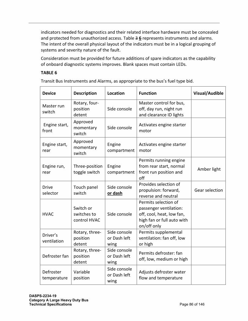
DASPS-2234-19 Category A Large Heavy Duty Bus Technical Specifications Page 86 of 146
indicators needed for diagnostics and their related interface hardware must be concealed and protected from unauthorized access. Table 3 6 represents instruments and alarms. The intent of the overall physical layout of the indicators must be in a logical grouping of systems and severity nature of the fault.
Consideration must be provided for future additions of spare indicators as the capability of onboard diagnostic systems improves. Blank spaces must contain LEDs.
TABLE 6
Transit Bus Instruments and Alarms, as appropriate to the bus’s fuel type bid.
Device Description Location Function Visual/Audible
Master run switch
Rotary, four-position detent
Side console Master control for bus, off, day run, night run and clearance ID lights
Engine start, front
Approved momentary switch
Side console Activates engine starter motor
Engine start, rear
Approved momentary switch
Engine compartment
Activates engine starter motor
Engine run, rear
Three-position toggle switch
Engine compartment
Permits running engine from rear start, normal front run position and off
Amber light
Drive selector
Touch panel switch
Side console or dash
Provides selection of propulsion: forward, reverse and neutral
Gear selection
HVAC Switch or switches to control HVAC
Side console
Permits selection of passenger ventilation: off, cool, heat, low fan, high fan or full auto with on/off only
Driver’s ventilation
Rotary, three-position detent
Side console or Dash left wing
Permits supplemental ventilation: fan off, low or high
Defroster fan Rotary, three-position detent
Side console or Dash left wing
Permits defroster: fan off, low, medium or high
Defroster temperature
Variable position
Side console or Dash left wing
Adjusts defroster water flow and temperature

DASPS-2234-19 Category A Large Heavy Duty Bus Technical Specifications Page 87 of 146
Windshield wiper
One-variable rotary position operating both wipers
Dash left wing
Variable speed control of left and right windshield wipers
Windshield washer Push button Dash left
wing Activates windshield washers
Dash panel lights
Rotary rheostat or stepping switch
Side Console or Dash left wing
Provides adjustment for light intensity in night run position
Interior lights Three-position switch Side console
Selects mode of passenger compartment lighting: off, on, normal
Fast idle Two-position switch Side console Selects high idle speed of
engine
WC ramp/ kneel enable
Two-position switch or other approved switch method
Side console or Dash right wing
Permits operation of ramp and kneel operations at each door remote panel
Amber light
Front door ramp/kneel enable
Two-position keyed switch1
Front door remote or Dash right wing
Permits ramp and kneel activation from front door area, key required1
Amber light
Front door ramp
Three-position momentary switch
Right side of steering wheel
Permits deploy and stow of front ramp Red light
Front kneel Three-position momentary switch
Front door remote
Permits kneeling activation and raise and normal at front door remote location
Amber or red dash indicator. Ext alarm and Amber light
Rear door ramp/kneel enable if applicable
Two-position keyed switch1
Rear door remote
Permits ramp and kneel activation from rear door area, key required1
Red light
Rear door ramp if applicable
Three-position momentary switch
Rear door remote
Permits deploy and stow of rear ramp

DASPS-2234-19 Category A Large Heavy Duty Bus Technical Specifications Page 88 of 146
Rear kneel Three-position momentary switch
Rear door remote
Permits kneeling activation and raise and normal at rear door remote location
Silent alarm
Recessed push button NO and NC contacts momentary
Side console
Activates emergency radio alarm at dispatch and permits covert microphone and/or enables destination sign emergency message
Video system event switch
Momentary on/off momentary switch with plastic guard
Side console Triggers event equipment, triggers event light on dash
Amber light
Left remote mirror
Four-position toggle type Side console
Permits two-axis adjustment of left exterior mirror
Right remote mirror
Four-position toggle type Side console
Permits two-axis adjustment of right exterior mirror
Mirror heater
Switch or temperature activated
Side console Permits heating of outside mirrors when required
Passenger door control
Five-position handle type detent or two momentary push buttons
Side console, forward
Permits open/close control of front and rear passenger doors
Red light
Rear door override
Two-position switch in approved location
Side console, forward
Allows driver to override activation of rear door passenger tape switches
Engine shutdown override
Momentary switch with operation protection (not required on electric bus)
Side console Permits driver to override auto engine shutdown

DASPS-2234-19 Category A Large Heavy Duty Bus Technical Specifications Page 89 of 146
Hazard flashers
Two-position switch
Side console or Dash right wing
Activates emergency flashers
Two green lights
Fire suppression
Red push button with protective cover
Dash left wing or dash center
Permits driver to override and manually discharge fire suppression system
Red light
Mobile data terminal
Mobile data terminal coach operator interface panel
Above right dash wing
Facilitates driver interaction with communication system and master log-on
LCD display with visual status and text messages
Farebox interface
Farebox coach operator interface panel
Near farebox Facilitates driver interaction with farebox system
LCD display
Destination sign interface
Destination sign interface panel
in approved location
Facilitates driver interaction with destination sign system, manual entry
LCD display
Turn signals
Momentary push button (two required) raised from other switches
Left foot panel
Activates left and right turn signals
Two green lights and optional audible indicator
PA manual Momentary push button
In approved location
Permits driver to manually activate public address microphone
Low profile or hands free microphone
Low-profile discrete mounting
Steering column or other approved location
Permits driver to make announcements with both hands on the wheel and focusing on road conditions
High beam Detented push button
In approved location
Permits driver to toggle between low and high beam
Blue light
Parking brake
Pneumatic PPV
Side console or Dash left wing
Permits driver to apply and release parking brake
Red light

DASPS-2234-19 Category A Large Heavy Duty Bus Technical Specifications Page 90 of 146
Park brake release
Pneumatic PPV
Vertical side of the side console or dash center
Permits driver to push and hold to release brakes
Hill holder Two-position momentary switch
Side console Applies brakes to prevent bus from rolling
Remote engine speed (not applicable to electric bus)
Rotary rheostat
Engine compartment
Permits technician to raise and lower engine RPM from engine compartment
Master door/ interlock
Multi-pole toggle, detented
Out of operator’s reach
Permits driver override to disable door and brake/throttle interlock
Red light
Warning interlocks deactivated
Red indicator light
Dash panel center
Illuminates to warn drive that interlocks have been deactivated
Red light
Retarder disable
Multi-pole switch detented
Within reach of Operator or approved location
Permits driver override to disable brake retardation/regeneration
Red light
Rear door passenger sensor disable
Multi-pole toggle, detented
In sign compartment or Driver’s barrier compartment
Permits driver to override rear door passenger sensing system
Indicator/ alarm test button
Momentary switch or programming1
Dash center panel
Permits driver to activate test of sentry, indicators and audible alarms
All visuals and audibles
Auxiliary power
110-volt power receptacle
Approved location
Property to specify what function to supply Speedometer
Speedometer
odometer, and diagnostic capability, 5-mile increments
Dash center panel
Visual indication of speed and distance traveled, accumulated vehicle mileage, fault condition display
Visual

DASPS-2234-19 Category A Large Heavy Duty Bus Technical Specifications Page 91 of 146
Air pressure gauge
Primary and secondary, 5 psi increments
Dash center panel
Visual indication of primary and secondary air systems
Red light and buzzer
Fire detection
Coach operator display
Property specific or dash center
Indication of fire detection activation by zone/location
Buzzer and red light
Door obstruction
Sensing of door obstruction
Dash center Indication of rear door sensitive edge activation
Red light and buzzer
Door ajar Door not properly closed
Property specific or dash center
Indication of rear door not properly closed
Buzzer or alarm and red light
Low system air pressure
Sensing low primary and secondary air tank pressure
Dash center Indication of low air system pressure
Buzzer and red light
(CNG, RNG only) Methane detection function
Detection of system integrity
Property specific or dash center
Detects system failure No start condition, amber light
Methane detection
Indication of 20% LED emergency light (LEL)
Property specific or dash center
Detects levels of methane
Flashing red at 20% LEL
Methane detection
Indication of 50% LEL
Property specific or dash center
Detects levels of methane
Solid red at 50% LEL
Engine coolant indicator
Low coolant indicator may be supplied as audible alert and visual and/or text message
Within driver’s sight
Detects low coolant condition Amber light

DASPS-2234-19 Category A Large Heavy Duty Bus Technical Specifications Page 92 of 146
Hot engine indicator
Coolant temperature indicator may be supplied as audible alert and visual and/or text message
Within driver’s sight
Detects hot engine condition and initiates time delay shutdown
Red light
Engine oil pressure indicator
Low engine oil pressure indicator may be supplied as audible alert and visual and/or text message
Within driver’s sight
Detects low engine oil pressure condition and initiates time-delayed shutdown
Red light
ABS indicator Detects system status Dash center Displays system failure Amber light
HVAC indicator
Detects system status Dash center Displays system failure Amber or red
light
Charging system indicator (12/24 V)
Detect charging system status
Dash center
Detects no charge condition and optionally detects battery high, low, imbalance, no charge condition, and initiates time-delayed shutdown
Red light flashing or solid based on condition
Bike rack deployed indicator
Detects bike rack position Dash center
Indication of bike rack not being in fully stowed position
Amber or red light
Fuel tank level
Analog gauge, graduated based on fuel type
Dash center Indication of fuel tank level/pressure

DASPS-2234-19 Category A Large Heavy Duty Bus Technical Specifications Page 93 of 146
DEF gauge Level Indicator Center dash Displays level of DEF tank and indicates with warning light when low
Red light
Active regeneration Detects Status Dash center Indication of electric
regeneration Amber or red light
1. Indicate area by drawing. Break up switches control from indicator lights.
24.6 Driver Foot Controls
Accelerator and brake pedals must be designed for ankle motion. Foot surfaces of the pedals must be faced with wear-resistant, nonskid, replaceable material.
24.7 Pedal Angle
The vertical angle of the accelerator and brake pedals must be determined from a horizontal plane regardless of the slope of the cab floor. The accelerator and brake pedals must be positioned at an angle of 37 to 50 degrees at the point of initiation of contact and extend downward to an angle of 10 to 18 degrees at full throttle.
The location of the brake and accelerator pedals must be determined by the manufacturer, based on space needs, visibility, lower edge of windshield, and vertical H-point.
24.7.1 Pedal Dimensions and Position The floor-mounted accelerator pedal must be 10 to 12 in. long and 3 to 4 in. wide. Clearance around the pedal must allow for no interference precluding operation.
24.7.2 1 to 2 in. Between Brake and Accelerator Pedals The accelerator and brake pedals must be positioned such that the spacing between them, measured at the heel of the pedals, is between 1 and 2 in. Both pedals must be located approximately on the same plane coincident to the surface of the pedals.
24.8 Brake and Accelerator Pedals 24.8.1 Adjustable Brake and Accelerator Pedals
Both pedals must be adjustable forward and rearward a minimum of 3 in. The adjustment shall be made by use of a dash-mounted toggle or rocker switch. The switch must be clearly labeled to identify it as pedal adjustment and must be within easy reach of the driver. Pedal adjustment must be enabled only when the bus is stationary and the parking brake engaged.
.
24.9 Driver Foot Switches 24.9.1 Floor-Mounted Foot Control Platform

DASPS-2234-19 Category A Large Heavy Duty Bus Technical Specifications Page 94 of 146
The angle of the turn signal platform must be determined from a horizontal plane, regardless of the slope of the cab floor. The turn signal platform must be angled at a minimum of 10 degrees and a maximum of 37 degrees. It must be located no closer to the seat front than the heel point of the accelerator pedal.
24.9.2 Turn Signal Controls Turn signal controls must be floor-mounted, foot-controlled, water-resistant, heavy-duty, momentary contact switches.
24.9.3 Foot Switch Control The control switches for the turn signals must be mounted on an inclined, floor-mounted stainless-steel enclosure or metal plate mounted to an incline integrated into the driver’s platform, located to the left of the steering column. The location and design of this enclosure must be such that foot room for the operator is not impeded. The inclined mounting surface must be skid-resistant. All other signals, including high beam and public address system must be in approved location.
The foot switches must be UL-listed, heavy-duty type, of a rugged, corrosion-resistant metal construction.
The foot switches for the directionals must be momentary type, while those for the PA system and the high beam must be latching type. The spacing of the switches must be such that inadvertent simultaneous deflection of switches is prevented.
24.9.4 Other Floor-Mounted Controls The following may be floor mounted, momentary or latching, as identified by the Authorized Purchaser at the preproduction meeting.
• hazard • silent alarm • PA system
24.10 Driver’s Amenities
24.11 Coat Hook A suitable hanger must be installed in a convenient, approved location for the driver coat. (Coat hook and loop is optional)
24.12 Drink Holder A device must be installed to securely hold the driver’s drink container, which may vary widely in diameter. It must be mounted within easy reach of the driver and must have sufficient vertical clearance for easy removal of the container. When the container is in the device, the driver’s view of the road must not be obstructed, and leakage from the container must not fall on any switches, gauges or controls.
This is to be selected by the Authorized Purchaser at the pre-production meeting.
DASPS-2234-19 Category A Large Heavy Duty Bus Technical Specifications Page 95 of 146
24.13 Windshield Wipers The bus must be equipped with electric windshield wipers for each half of the windshield. At 60 mph, no more than 10 percent of the wiped area must be lost due to windshield wiper lift. For two- piece windshields, both wipers must park along the center edges of the windshield glass. For single-piece windshields, wipers must park along the bottom edge of the windshield. Windshield wiper motors and mechanisms must be easily accessible for repairs or service. The fastener that secures the wiper arm to the drive mechanism must be corrosion-resistant.
Intermittent Wiper with Variable Control
A variable-speed feature must be installed to allow adjustment of wiper speed for each side of the windshield between approximately five (5) and twenty-five (25) cycles per minute.
Non-Synchronized Wipers
For non-synchronized wipers, separate controls for each side must be supplied. A single control switch for non-synchronized wipers may be optional.
24.14 Windshield Washers The windshield washer system, when used with the wipers, must deposit washing fluid evenly and completely wet the entire wiped area. The windshield washer system must have a minimum 2.5-gallon reservoir, located for easy refilling from outside of the bus. Reservoir pumps, lines and fittings must be corrosion-resistant and must include a means to determine fluid level.
25 DRIVER’S SEAT
25.1 Dimensions
The driver’s seat must be comfortable and adjustable so that people ranging in size from a 95th-percentile male to a 5th-percentile female may operate the bus.
25.2 Seat Pan Cushion Length
Measurement must be from the front edge of the seat pan to the rear at its intersection with the seat back. The adjustment of the seat pan length must be no less than 16.5 in. at its minimum length and no more than 20.5 in. at its maximum length.
25.3 Seat Pan Cushion Height Dimensions
Measurement must be from the cab floor to the top of the level seat at its center midpoint. The seat must adjust in height from a minimum of 14 in., with a minimum 6 in. vertical range of adjustment.

DASPS-2234-19 Category A Large Heavy Duty Bus Technical Specifications Page 96 of 146
25.4 Seat Pan Cushion Slope
Measurement is the slope of the plane created by connecting the two high points of the seat, one at the rear of the seat at its intersection with the seat back and the other at the front of the seat just before it waterfalls downward at the edge. The slope can be measured using an inclinometer and must be stated in degrees of incline relative to the horizontal plane (0 degrees). The seat pan must adjust in its slope from no less than plus 12 deg. (rearward “bucket seat” incline), to no less than minus 5 deg. (forward slope).
25.5 Seat Base Fore/Aft Adjustment
Measurement is the horizontal distance from the heel point to the front edge of the seat. The minimum and maximum distances must be measured from the front edge of the seat when it is adjusted to its minimum seat pan depth (approximately 15 in.). On all low-floor buses, the seat-base must travel horizontally a minimum of 9 in. It must adjust no closer to the heel point than 6 in.
25.6 Seat Pan Cushion Width
Measurement is the horizontal distance across the seat cushion. The seat pan cushion must be 17 to 21 in. across at the front edge of the seat cushion and 20 to 23 in. across at the side bolsters.
25.7 Seat Suspension
The driver’s seat must be appropriately dampened to support a minimum weight of 380 lbs. The suspension must be capable of dampening adjustment in both directions. Rubber snubbers must be provided to prevent metal-to-metal contact.
25.8 Seat Back - Width
Measurement is the distance between the outermost points of the front of the seat back, at or near its midpoint in height. The seat back width must be no less than 19 in. Seat back must include dual recliner gears on both sides of the seat.
25.9 Height
Standard height seat back
25.10 Headrest
Adjustable headrest
25.11 Seat Back Lumbar Support
Measurement is from the bottom of the seat back at its intersection with the seat pan to the top of the lumbar cushioning. The seat back must provide adjustable depth lumbar back support with three individual operating lumbar cells within a minimum range of 7 to 11 in.

DASPS-2234-19 Category A Large Heavy Duty Bus Technical Specifications Page 97 of 146
25.12 Seat Back Angle Adjustment
The seat back angle must be measured relative to a level seat pan, where 90 degrees is the upright position and 90 degrees-plus represents the amount of recline.
The seat back must adjust in angle from a minimum of no more than 90 degrees (upright) to at least 105 degrees (reclined), with infinite adjustment in between.
25.13 Seat Belt
The belt assembly must be an auto-locking retractor (ALR) lap seat belt only. All seat belts must be stored in automatic retractors. The belts must be mounted to the seat frame so that the driver may adjust the seat without resetting the seat belt.
The seat and seat belt assemblies as installed in the bus must withstand static horizontal forces as required in FMVSS 207 and 210. Seatbelt webbing must be black in color.
25.14 Seat Control Locations
While seated, the driver must be able to make seat adjustments by hand without complexity, excessive effort or being pinched. Adjustment mechanisms must hold the adjustments and must not be subject to inadvertent changes.
25.15 Seat Structure and Materials - Cushions
Cushions must be fully padded with at least 3 in. of materials in the seating areas at the bottom and back.
25.16 Cushion Materials
All materials used on the seat assembly, passenger and driver's seat must meet the flammability requirements of the FMVSS #302. Proof of Compliance must be submitted with proposals.
25.17 Pedestal
Powder-coated steel.
Exposed portions of frame and hardware must be stainless steel plated may be listed as an option.
Contractors may make available, as an option, a silicone cushion for the driver’s seat and a driver’s seat vacancy alarm system.
26 MIRRORS
26.1 Exterior Mirrors
All mirrors must conform to the current requirements of the state in which the bus is operating in. Exterior mirrors must be heated and remote controlled motorized with stainless steel arms that return to original position when moved.

DASPS-2234-19 Category A Large Heavy Duty Bus Technical Specifications Page 98 of 146
Powder coated may be offered as an optional and included on options list.
The bus must be equipped with corrosion-resistant, outside rearview mirrors mounted with stable supports to minimize vibration. Mirrors must be firmly attached to the bus to minimize vibration and to prevent loss of adjustment with a breakaway mounting system. Mirrors must permit the driver to view the roadway along the sides of the bus, including the rear wheels. Mirrors must be positioned to prevent blind spots. Mirrors must retract or fold sufficiently to allow bus washing operations but avoid contact with windshield.
Base bus must include a three inch convex mirror that is mounted in the lower right corner of the right side flat mirror. Mirrors must fold out of way of automatic washer. Metal mirror parts to be chrome plated or stainless steel. The backs of inside mirrors must be painted flat black where necessary to comply with FMVSS.
An optional high mount street side mirror may be made available and included to the options list, with selection made at the preproduction meeting. Exterior mirrors must utilize a “quick disconnect” for electrical wiring.
An optional set of manual 8" X 8" and 6” spot mirrors on stainless steel arms located on each side of the vehicle may be included to the options list.
26.2 Interior Mirrors
Mirrors must be installed for the driver to observe passengers throughout the bus without leaving the seat and without shoulder movement. The driver must be able to observe passengers in the front/entrance and rear/exit areas, anywhere in the aisle, and in the rear seats.
A (min) 8 1/2” x 16” rear view mirror must be installed on the front sign header. A 6" diameter adjustable convex mirror over and forward of the front door must be installed. An adjustable convex mirror must be installed over/above and to the rear of the rear exit door. (Convex mirrors described above are to be used in conjunction with each other.) The glass in this mirror must be replaceable.
27 WINDOWS
27.1 General
A minimum of 8,000 sq in. of window area, including operator and door windows, must be required on each side of the standard 35-ft length configured bus.
A minimum of 10,000 sq in. of window area, including operator and door windows, must be required on each side of the standard 40-ft length configured bus.
A minimum of 12,000 sq in. of window area, including operator and door windows, must be required on each side of the standard 45-ft length configured bus.

DASPS-2234-19 Category A Large Heavy Duty Bus Technical Specifications Page 99 of 146
27.2 Windshield
The windshield must permit an operator’s field of view as referenced in SAE Recommended Practice J1050. The vertically upward view must be a minimum of 14 degrees, measured above the horizontal and excluding any shaded band. The vertically downward view must permit detection of an object 3½ ft high no more than 2 ft in front of the bus. The horizontal view must be a minimum of 90 degrees above the line of sight. Any binocular obscuration due to a center divider may be ignored when determining the 90- degree requirement, provided that the divider does not exceed a 3-degree angle in the operator’s field of view. Windshield pillars must not exceed 10 degrees of binocular obscuration. The windshield must be designed and installed to minimize external glare as well as reflections from inside the bus.
The windshield must be easily replaceable.
27.3 Glazing
The windshield glazing material must have a ¼ in. nominal thickness laminated safety glass conforming to the requirements of ANSI Z26.1 Test Grouping 1A and the Recommended Practices defined in SAE J673.
Shaded windshield band may be an option and included on options list.
27.4 Driver’s Side Window
The driver’s side window must be the sliding type, requiring only the rear half of sash to latch upon closing, and must open sufficiently to permit the seated operator to easily adjust the street-side outside rearview mirror. When in an open position, the window must not rattle or close during braking. This window section must slide in tracks or channels designed to last the service life of the bus. The operator’s side window must not be bonded in place and must be easily replaceable. The glazing material must have a single-density tint.
The driver’s view, perpendicular through operator’s side window glazing, must extend a minimum of 33 in. (840 mm) to the rear of the heel point on the accelerator, and in any case must accommodate a 95th percentile male operator. The view through the glazing at the front of the assembly must begin not more than 26 in. (560 mm) above the operator’s floor to ensure visibility of an under-mounted convex mirror. Driver’s window construction must maximize ability for full opening of the window.
The driver’s side window glazing material must have a ¼ in. nominal thickness laminated safety glass conforming with the requirements of ANSI Z26.1-1996 Test Grouping 2 and the Recommended Practices defined in SAE J673.
The design must prevent sections from freezing closed in the winter. Light transmittance must be 75 percent on the glass area below 53 in. from the operator platform floor. On the top fixed over bottom slider configuration, the top fixed area above 53 in. may have a maximum 5 percent light transmittance.

DASPS-2234-19 Category A Large Heavy Duty Bus Technical Specifications Page 100 of 146
27.5 Side Windows
The side windows must be fixed framed transom. With the exception of the upper portion of first right-hand and /or left-hand window where the side destination sign must be located, all other must be glazed with tinted, flat panel, uniform sized, transit application approved laminated safety glass (ANSI 25.1). Glazing in the sash must be easily replaced without removing the sash from the bus. Side window sliders must be equipped with metal latches. Components known to meet these requirements include, but are not limited to, Excel full sliders, and the Transit Care 3 minute windows.
An option of fixed frame and/or full slider style windows may be made available and be included on options list. All windows must be of 7/32" 28% gray tinted safety glass and frame windows must have black (dark) polyester powder coat aluminum frames inside and out. Glass must be mounted in removable rubber retaining strips/seals.
Base bus must have flush mounted windows with liners attached, no sliding partition installed.
All tempered glass must have liners attached.
Frame must be assembled with anti-corrosion coated screws and fasteners to enable changing glass. A positive lock type emergency latch meeting the FMVSS-217 must be furnished on each window frame.
Emergency egress window must have a permanent decal describing emergency window operation procedures. Side windows must be designed to prevent the entrance of air and water when windows are closed. The window seal rubber must be installed so that passengers cannot remove it and rubber must be of such quality to resist adhering to other sash sill.
Color of glazing material in all side windows, with the exception of the side destination sign window, must be of Gray 28% or equivalent. The side destination sign windows must be clear. Windows on the bus sides and in the rear door must be tinted a neutral color, complementary to the bus exterior. The maximum solar energy transmittance must not exceed 37 percent, as measured by ASTM E- 424, and the luminous transmittance must be no less than 16 percent, as measured by ASTM D-1003.
Window at the destination/location sign must not be tinted in the vicinity of the sign.
28 HEATING, VENTILATING AND AIR CONDITIONING
28.1 Capacity and Performance
Interior climate control must be automated controls capable of maintaining the interior of the bus at a level suitable for all climate conditions found in the continental United States. The heating, ventilating, and cooling systems must maintain an average passenger compartment temperature 42 between 65 and 80 degrees F with a relative humidity of

DASPS-2234-19 Category A Large Heavy Duty Bus Technical Specifications Page 101 of 146
70 percent or less. The system must maintain these conditions in ambient temperatures of –10 to 110 degrees F with ambient humilities of 5 to 50 percent while the bus is running on the design operating profile with a full-seated load of passengers with door openings for 30 seconds or more every 3 minutes. In ambient temperatures of 10 to –10 degrees F, the average temperature must not fall below 65 degrees F while the bus is running on design operating profile with no passengers. The temperature measured from a height of 6 inches below the ceiling must be within +/- 5 degrees F of the average temperature at the top surface of the seat cushions. Temperatures measured more than 3 inches above the floor must be within +/- 5 degrees F of the average temperature at the top surface of the seat cushions. The interior temperature, from front to rear of the bus, must not vary more than a +/- 5 degrees F from the average. System must be programmable by each technician. The cooling mode must be capable of reducing the passenger compartment temperature from 100 degrees F to 80 degrees F in less than 30 minutes after the engine start up under the following conditions. Engine temperature must be within the normal operating range at the time of startup of the cool down test and the engine speed must be limited to fast idle that may be activated by a driver controlled device. The bus must be parked in direct sunlight with ambient temperature at 100 degrees F and humidity less than 60 percent. There must be no passengers onboard and the doors must be closed. The cooling mode may operate independent of the propulsion system and outside air may be cut off during the cool down period. Manually controlled shutoff valves in the refrigerant lines must allow isolation of the compressor and receiver for service. To the extent practicable, self-sealing couplings must be used to isolate the refrigerant lines during removal of major components such as refrigerant compressor or condenser. The condenser must be located to efficiently transfer heat to the atmosphere, and must not ingest air warmed by the bus mechanical equivalent above the ambient temperature or discharge air into any other system of the bus. The location of the condenser must preclude its obstruction by wheel splash, road dirt or debris. Bidders must supply Thermo King Screw design (Intelligent Air) or approved equal. The lower A/C compressor and upper condenser/evaporator package must be of the same manufacturer. Freon must be 134A.
The door opening average is approximately every 2 minutes; the A/C system must be capable of handling the heat load by maintaining a temperature of 20 degrees less than ambient and humidity level less than 40% at any point or time with 40 plus passengers at 100 degrees in direct sun light.

DASPS-2234-19 Category A Large Heavy Duty Bus Technical Specifications Page 102 of 146
Note. Air conditioning requirements for hybrid drive batteries, if necessary, must not activate or degrade the efficiency of the passenger HVAC system.
HVAC unit and controls to be 'Thermo King' or equivalent, Provide one set of software, including diagnostic cables, with the first production bus in each order group. Additional sets may be priced separately.
For Electric Buses provide ThermoKing Electric A/C rear or roof mounted with Intelligaire III controls and CAN Based diagnostics or equivalent.
The HVAC system excluding the operator's heater/defroster must be centrally controlled with an advanced electronic/diagnostic control system with provisions for extracting/reading data.
Driver's control must be an IntelligAIRE III or approved equal standard four-key keypad. Settings must not be lost when the master switch is turned off.
The HVAC unit and controls known to meet the minimum requirements are the 'Thermo King' Intelligaire III, or equivalent with standard 4 key keypad driver control, utilizing a model S391 for less than 60 foot buses.
Manufacturers must provide one set of 'SMART-PAC' software, including diagnostic cables, with the first production bus in each order group. Additional sets may be priced separately. Provide an additional data port in or near the driver's area. The HVAC system excluding the operator's heater/defroster must be centrally controlled with an advanced electronic/diagnostic control system with provisions for extracting/reading data. Settings must not be lost when the master switch is turned off.
There must be manual shut off valves to isolate the drier, receiver, and compressor.
The interior heating system must maintain the interior of the bus at a level suitable for all climate conditions found throughout the State of Oregon The heating, ventilation, and cooling system must maintain an average passenger compartment temperature between 65 degrees and 80 degrees Fahrenheit with a relative humidity of 50 percent or less.
Manually-controlled corrosion resistant shut-off valves in the refrigerant lines must allow isolation of the compressor and receiver for service. To the extent practicable, self-sealing couplings must be used to break and seal the refrigerant lines during removal of major components such as the refrigerant compressor or condenser. Suction and discharge lines must be positioned and secured not to contact each other or any part of the body or frame of the bus.
The air conditioning system must be a roof or rear mount unit, and utilize Refrigerant R134a, R407c, or R1234YF.
System capacity must have a minimum of 45,000 BTU's with 1,800 CFM at 0.5" water static in duct.
The condenser fans and evaporator blowers must be Thermo King or equivalent brushless motors with 3 2 year warranty.

DASPS-2234-19 Category A Large Heavy Duty Bus Technical Specifications Page 103 of 146
Suction and discharge ports must be easily accessible through the main engine compartment door.
Manual shutoff valves in the refrigerant lines must allow isolation of the compressor and dryer unit for service.
A safety lanyard on overhead HVAC filter/return air grilles must be provided.
The Air Conditioning unit installation must be certified in writing by the vehicle manufacturer as being designed, manufactured, and installed in accordance with the manufacturer’s requirements before acceptance and delivery of vehicles.
28.2 Controls and Temperature Uniformity
The HVAC system excluding the driver’s heater/defroster must be centrally controlled with an advanced electronic/diagnostic control system with provisions for extracting/reading data. The system must be compliant with J1939 Communication Protocol for receiving and broadcasting of data.
Hot engine coolant water, if applicable, must be delivered to the HVAC system driver’s defroster/heater and other heater cores by means of an auxiliary coolant pump, sized for the required flow, which is brushless and seal-less having a minimum maintenance free service life for both the brushless motor and the pump of at least 40,000 hours at full power.
28.3 Manual Mode Selection of Climate Control System
After manual selection and/or activation of climate control system operation mode, all interior climate control system requirements for the selected mode must be attained automatically to within ±2 °F of specified temperature control set-point.
28.4 Manually Adjustable Temperature Control Set Point
The climate control system must have the provision to allow the driver to adjust the temperature control set-point at a minimum of between 68 and 72 °F. From then on, all interior climate control system requirements must be attained automatically, unless re-adjusted by driver.
The driver must have full control over the defroster and driver’s heater. The driver must be able to adjust the temperature in the driver’s area through air distribution and fans. The interior climate control system must switch automatically to the ventilating mode if the refrigerant compressor or condenser fan fails.
Interior temperature distribution must be uniform to the extent practicable to prevent hot and/or cold spots. After stabilization with doors closed, the temperatures between any two points in the passenger compartment in the same vertical plane, and 6 to 72 in. above the floor, must not vary by more than 5 °F with doors closed. The interior temperatures, measured at the same height above the floor, must not vary more than ± 5 °F from the front to the rear from the average temperature determined in accordance with APTA’s “Recommended Instrumentation and Performance Testing for Transit Bus Air

DASPS-2234-19 Category A Large Heavy Duty Bus Technical Specifications Page 104 of 146
Conditioning System.” Variations of greater than ± 5 °F will be allowed for limited, localized areas provided the majority of the measured temperatures fall within the specified requirement.
28.5 Air Flow - Passenger Area
The cooling mode of the interior climate control system must introduce air into the bus at or near the ceiling height at a minimum rate of 25 cubic ft per minute (cfm) per passenger based on the standard configuration bus carrying a number of passengers equal to 150 percent of the seated load. Airflow must be evenly distributed throughout the bus, with air velocity not exceeding 100 ft per minute on any passenger. The ventilating mode must provide air at a minimum flow rate of 20 cfm per passenger.
Airflow may be reduced to 15 cfm per passenger (150 percent of seated load) when operating in the heating mode. The fans must not activate until the heating element has warmed sufficiently to ensure at least 70 °F air outlet temperature. The heating air outlet temperature must not exceed 120 °F under any normal operating conditions.
The climate control blower motors and fan must be designed such that their operation complies with the interior noise level requirements.
28.6 Air Flow - Driver’s Area
The bus interior climate control system must deliver at least 100 cfm of air to the driver’s area when operating in the ventilating and cooling modes. Adjustable nozzles must permit variable distribution or shutdown of the airflow. Airflow in the heating mode must be reduced proportionally to the reduction of airflow into the passenger area. The windshield defroster unit must meet the requirements of SAE
Recommended Practice J382, “Windshield Defrosting Systems Performance Requirements,” and must have the capability of diverting heated air to the driver’s feet and legs. The defroster or interior climate control system must maintain visibility through the driver’s side window.
28.7 Controls for the Climate Control System (CCS)
The controls for the driver’s compartment for heating, ventilation and cooling systems must be integrated and must meet the following requirements:
• The heat/defrost system fan must be controlled by a separate switch that has an “off” position and at least two positions for speed control. All switches and controls must preclude the possibility of clothing becoming entangled, and shields must be provided, if required. If the fans are approved by the Authorized Purchaser, an “on-off” switch must be located to the right of or near the main defroster switch.
• A manually operated control valve must control the coolant flow through the heater core.
• If a cable-operated manual control valve is used, the cable length must be kept to a minimum to reduce cable seizing. Heater water control valves must be “positive”

DASPS-2234-19 Category A Large Heavy Duty Bus Technical Specifications Page 105 of 146
type, closed or open. The method of operating remote valves must require the concurrence of the Authorized Purchaser project manager.
28.8 Driver’s Compartment Requirements
A separate heating, ventilation and defroster system for the driver’s area must be installed and must be controlled by the driver. The system must meet the following requirements:
• The heater and defroster system must provide heating for the driver and heated air to completely defrost and defog the windshield, driver’s side window, and the front door glasses in all operating conditions. Fan(s) must be able to draw air from the bus body interior and/or the exterior through a control device and pass it through the heater core to the defroster system and over the driver’s feet. A minimum capacity of 100 cfm must be provided. The driver must have complete control of the heat and fresh airflow for the driver’s area.
• The defroster supply outlets must be located at the lower edge of the windshield. These outlets must be durable and must be free of sharp edges that can catch clothes during normal daily cleaning. The system must be such that foreign objects such as coins or tickets cannot fall into the defroster air outlets. Adjustable ball vents or louvers must be installed at the left of the driver’s position to allow direction of air onto the side windows.
A ventilation system must be installed to ensure driver comfort and must be capable of providing fresh air in the driver’s area. Vents must be controllable by the driver from the normal driving position. Decals must be installed, indicating “operating instructions” and “open” and “closed” positions. When closed, vents must be sealed to prevent the migration of water or air into the bus if applicable.
The bus interior climate control system must deliver at least 100 cubic feet per minute of air to the driver's area when operating in the ventilation, heating, and cooling modes without use of the driver's booster fan. The climate control system blower motors must operate at the set speed during all operating modes. All return air ducts must be protected by guards constructed of a sturdy mesh which will resist damage.
Adjustable nozzles must permit variable distribution or shut down of all air flow. The defroster and/or interior climate control system must maintain visibility through the driver's side window. Must have ability to provide increased air flow to the operator.
The windshield defroster unit must meet or exceed all requirements of SAE Recommended Practice J382, Windshield Defrosting Systems Performance Requirements, and must have the capability of diverting heated air to the driver's feet and legs.
28.9 Air Filtration
Air must be filtered before discharge into the passenger compartment. The filter must meet the ANSI/ASHRAE 52.1 requirement for 5 percent or better atmospheric dust spot efficiency, 50 percent weight arrestance, and a minimum dust holding capacity of 120 g

DASPS-2234-19 Category A Large Heavy Duty Bus Technical Specifications Page 106 of 146
per 1000 cfm cell. Air filters must be easily removable for service. All air filters must be easily accessible without the need to disassemble other parts to access the filter.
28.10 Cleanable Filters
Air filters must be cleanable.
28.11 Roof Ventilators - One Roof Ventilators
A minimum of one (1) roof ventilators must be installed in the roof of the bus. Additional manual or power-operated roof ventilator can be added as option.
Each ventilator must be easily opened and closed manually. When open with the bus in motion, this ventilator must provide fresh air inside the bus. The ventilator must cover an opening area no less than 425 sq in. and must be capable of being positioned as a scoop with either the leading or trailing edge open no less than 4 in., or with all four edges raised simultaneously to a height of no less than 3½ in. An escape hatch must be incorporated into the roof ventilator. Roof ventilator(s) must be sealed to prevent entry of water when closed.
28.12 Reserve
28.13 Maintainability
Manually controlled shut-off valves in the refrigerant lines must allow isolation of the compressor and dehydrator filter for service. To the extent practicable, self-sealing couplings utilizing O-ring seals must be used to break and seal the refrigerant lines during removal of major components, such as the refrigerant compressor. Shut-off valves may be provided in lieu of self-sealing couplings. The condenser must be located to efficiently transfer heat to the atmosphere and must not ingest air warmed above the ambient temperature by the bus mechanical equipment, or to discharge air into any other system of the bus. The location of the condenser must preclude its obstruction by wheel splash, road dirt or debris.
HVAC components located within 6 in. of floor level must be constructed to resist damage and corrosion.
High and low refrigerant pressure analog gauges to be located in the return air area.
28.14 Entrance/Exit Area Heating
Optional Entrance/Exit Area Heating may be included on options list.
Heat must be supplied to the entrance and exit areas to maintain a tread surface temperature no less than 35 °F in an ambient of -10 °F to prevent accumulation of snow, ice or slush with the bus operating under design operating profile and corresponding door opening cycle.
DASPS-2234-19 Category A Large Heavy Duty Bus Technical Specifications Page 107 of 146
28.15 Floor-Level Heating
28.15.1 Transit Coach
Optional Floor-Level Heating may be included on options list.
Sufficient floor-level heaters shall be provided to evenly supply heated forced air. Control of the floor-level heating shall be through the main heating system electronic control.
Optional Forced-Air Floor-Level Heating
Sufficient floor-level heaters shall be provided to evenly supply heated forced air through floor ducts across the length of the bus. Floor ducts may be discontinued at the upper level, but additional provisions to prevent cold floors and ensure temperature uniformity shall be included. Control of the floor-level heating shall be through the main heating system electronic control.
Optional Convector Air Floor-Level Heating may be included on options list.
Sufficient floor-level heaters must be provided that evenly supply convector air across the length of the bus. Control of the floor-level heating must be through the main heating system’s electronic control.
Optional Warm Wall Heating may be included on options list.
Sufficient heaters must be provided with ducting to blow warm air upward through a cavity in the wall and discharge the warm air at the base of the windows. Control of the warm wall heating must be through the main heating system electronic control.
28.15.2 Commuter Coach
Sufficient heaters must be provided with ducting to blow warm air upward through a cavity in the wall and discharge the warm air at the base of the windows. Control of the warm wall heating must be through the main heating system electronic control shall be optional.
29 EXTERIOR PANELS, FINISHES AND EXTERIOR LIGHTING
29.1 Design
The bus must have a clean, smooth, simple design, primarily derived from bus performance requirements and passenger service criteria. The exterior and body features, including grilles and louvers, must be shaped to facilitate cleaning by automatic bus washers without snagging washer brushes. Water and dirt must not be retained in or on any body feature to freeze or bleed out onto the bus after leaving the washer. The body and windows must be sealed to prevent leaking of air, dust or water under normal operating conditions and during cleaning in automatic bus washers for the service life of the bus.

DASPS-2234-19 Category A Large Heavy Duty Bus Technical Specifications Page 108 of 146
Exterior panels must be sufficiently stiff to minimize vibration, drumming or flexing while the bus is in service. When panels are lapped, the upper and forward panels must act as a watershed. However, if entry of moisture into the interior of the vehicle is prevented by other means, then rear cap panels may be lapped otherwise. The windows, hatches and doors must be able to be sealed. Accumulation of spray and splash generated by the bus’s wheels must be minimized on windows and mirrors.
29.2 Materials
Body materials must be selected by Contractor and the body fabricated to reduce maintenance, extend durability and provide consistency of appearance throughout the service life of the bus. Detailing must be kept simple, and add-on devices and trim must be minimized and integrated into the basic design.
29.3 Roof-Mounted Equipment
A non-skid, clearly marked walkway or steps must be incorporated on the roof to provide access to equipment without damaging any system or bus paneling.
29.4 Pedestrian Safety
Exterior protrusions along the side and front of the bus greater than ½ in. and within 80 in. of the ground must have a radius no less than the amount of the protrusion. The exterior rearview mirrors, cameras and required lights and reflectors are exempt from the protrusion requirement. Advertising frames must protrude no more than ⅞ in. from the body surface. Grilles, doors, bumpers and other features on the sides and rear of the bus must be designed to minimize toeholds or handholds.
Exterior protrusions must not cause a line-of-sight blockage for the driver.
29.5 Repair and Replacement - Side Body Panels
Structural elements supporting exterior body panels must allow side body panels below the windows to be repaired in lengths not greater than 12.5 ft.
29.6 Easily Replaceable Lower Side Body Panels
The lower section (approximately 17.5 in.) of the side body panels (low-floor buses) or skirt panels (highfloor buses) must be made of impact-resistant material and must be easily and quickly replaceable. This does not apply to electric buses.
29.7 Rain Gutters
Rain gutters must be installed to prevent water flowing from the roof onto the passenger doors and driver’s side window. When the bus is decelerated, the gutters must not drain onto the windshield, driver’s side window or door boarding area. Cross-sections of the gutters must be adequate for proper operation.

DASPS-2234-19 Category A Large Heavy Duty Bus Technical Specifications Page 109 of 146
29.8 License Plate Provisions
Provisions must be made to mount standard-size U.S. license plates per SAE J686 on the front and rear of the bus.
These provisions must direct-mount or recess the license plates so that they can be cleaned by automatic bus-washing equipment without being caught by the brushes. The rear license plate provision must be illuminated per SAE J587.
29.9 Fender Skirts
Features to minimize water spray from the bus in wet conditions must be included in wheel housing design. Any fender skirts must be easily replaceable. They must be flexible if they extend beyond the allowable body width. Wheels and tires must be removable with the fender skirts in place.
29.10 Standard Splash Aprons
Splash aprons, composed of ¼ in. minimum composition or rubberized fabric, must be installed behind and/or in front of wheels as needed to reduce road splash and protect underfloor components. The splash aprons must extend downward to within 6 in. off the road surface at static conditions. Apron widths must be no less than tire widths. Splash aprons must be bolted to the bus understructure. Splash aprons and their attachments must be inherently weaker than the structure to which they are attached. The flexible portions of the splash aprons must not be included in the road clearance measurements. Splash apron must be installed as necessary to protect the wheelchair loading device from road splash. Other splash aprons must be installed where necessary to protect bus equipment. An approved method of grounding static electricity must be installed on each bus such as a conductive nylon grounding strap.
29.11 Service Compartments and Access Doors - Access Doors
Conventional or pantograph hinged doors must be used for the engine compartment and for all auxiliary equipment compartments including doors for checking the quantity and adding to the engine coolant, engine lubricant and transmission fluid. Access openings must be sized for easy performance of tasks within the compartment, including tool operating space. Access doors must be of rugged construction and must maintain mechanical integrity and function under normal operations throughout the service life of the bus. They must close flush with the body surface. All doors must be hinged at the top or on the forward edge and must be prevented from coming loose or opening during transit service or in bus washing operations. All access doors must be retained in the open position by props or counterbalancing with over-center or gas-filled springs with safety props and must be easily operable by one person.
Springs and hinges must be corrosion resistant. Latch handles must be flush with, or recessed behind, the body contour and must be sized to provide an adequate grip for opening. Access doors, when opened, must not restrict access for servicing other components or systems. If precluded by design, the manufacturer shall provide door

DASPS-2234-19 Category A Large Heavy Duty Bus Technical Specifications Page 110 of 146
design information specifying how the requirements are met. The following options may be included with options list:
1. An engine oil pressure gauge and coolant temperature gauge with drag needle must be installed in the engine compartment. These gauges must be easily read during service and mounted in an area where they must not be damaged during minor or major repairs.
Electronic gauges may be included with options list.
2. Engine compartment lighting must be installed to adequately illuminate the area for night time service, emergency repairs, or adjustments. Sealed lamp assemblies must be installed and must be controlled by a switch located near the rear start controls in the engine compartment. The rear engine compartment lights must have an on/off switch.
3. Protective sleeves (high temperature resistant material) must be installed to all fire suppression system hoses, high pressure hydraulic lines for hydraulic pump and power steering.
29.12 Access Door Latch/Locks
The engine compartment, including the exhaust duct plenum, must be completely sealed to prevent smoke or fumes from entering the bus interior. The engine bulkhead and exhaust duct plenum must be insulated adequately to prevent discomfort to passengers due to heat, to minimize hazard in case of fire in the engine compartment, and to aid in controlling noise to meet required levels.
An engine air intake designed to minimize noise must be installed. Insulation must be installed as needed in the engine compartment area for sound suppression.
An adequate number of fire detectors must be furnished in the engine compartment, as determined by the bus manufacturer. The detectors must activate an alarm (visual as well as audible) at the driver's station.
Access panels to the left and right side of the engine compartment must be installed with expanded metal inserts to provide heat dissipation in the engine compartment. Panels must also be constructed so that maintenance personnel can easily reach all under the floor and engine compartment equipment requiring access from outside the bus body. Access panels must be hinged to swing up and out of the way and be secured with a 5/16” square latch.
Gas operated shocks with safety locks must secure access doors in the open position during inspection and servicing. The engine compartment doors must be equipped with handles. Louvers must be installed in the rear engine compartment door to optimize airflow. Access doors are not required in the engine door.
Forward edge hinges with positive action hold open springs must be installed on the fuel connector and lay flat against the adjacent panel when fully opened. The battery access door must have top or leading edge hinges with gas operated shocks with safety devises
DASPS-2234-19 Category A Large Heavy Duty Bus Technical Specifications Page 111 of 146
when the battery is being serviced. A small access door must be installed to the battery disconnect switch, if it is not easily reached through the battery main box door.
Battery disconnect switch, fuel and air tank drain valve doors must be OEM standard doors and latch. A well type securing latch must be optional.
The following options may be included with options list:
1. An engine oil pressure gauge and coolant temperature gauge with drag needle must be installed in the engine compartment. These gauges must be easily read during service and mounted in an area where they must not be damaged during minor or major repairs.
2. Engine compartment lighting must be installed to adequately illuminate the area for night time service, emergency repairs, or adjustments. Sealed lamp assemblies must be installed and must be controlled by a switch located near the rear start controls in the engine compartment. When the rear engine compartment door is closed the compartment lights must extinguish automatically.
3. Protective sleeves (high temperature resistant material) must be installed to all fire suppression system hoses, high pressure hydraulic lines for hydraulic pump and power steering.
NOTE: option 1 is not applicable to battery electric buses.
29.13 Bumpers - Location
Bumpers must provide impact protection for the front and rear of the bus with the top of the bumper being 27 in., ± 2 in., above the ground. Bumper height must be such that when one bus is parked behind another, a portion of the bumper faces will contact each other.
29.14 Front Bumper
No part of the bus, including the bumper, must be damaged as a result of a 5 mph impact of the bus at curb weight with a fixed, flat barrier perpendicular to the bus’s longitudinal centerline. The bumper must return to its pre-impact shape within 10 minutes of the impact. The bumper must protect the bus from damage as a result of 6.5 mph impacts at any point by the common carriage with contoured impact surface defined in Figure 2 of FMVSS 301 loaded to 4000 lbs parallel to the longitudinal centerline of the bus. It must protect the bus from damage as a result of 5.5 mph impacts into the corners at a 30-degree angle to the longitudinal centerline of the bus. The energy absorption system of the bumper must be independent of every power system of the bus and must not require service or maintenance in normal operation during the service life of the bus. The bumper may increase the overall bus length specified by no more than 7 in. Mounting provisions must be made for integrating bike rack if necessary.

DASPS-2234-19 Category A Large Heavy Duty Bus Technical Specifications Page 112 of 146
29.15 Bicycle Racks
A bicycle rack must be installed and ready for use upon delivery of buses. Racks must be identical in style to the existing racks on current procuring agencies’ fleets. Racks must be unpainted stainless steel, powder coated black, or standard black. A bike rack deployed indicator light must be installed on the driver’s dash. Each rack must carry the manufacturer’s warranty from time of bus acceptance, and must include parts and labor. Components known to meet these requirements include, but are not limited to, Sports Works NW, Inc and Mid-West BYK-RAK. Rack installed will include operating instructions in both English and Spanish. Two and three bike rack options may be included on options list.
29.16 Rear Bumper
No part of the bus, including the bumper, must be damaged as a result of a 2 mph impact with a fixed, flat barrier perpendicular to the longitudinal centerline of the bus. The bumper must return to its pre-impact shape within 10 minutes of the impact. When using a yard tug with a smooth, flat plate bumper 2 ft wide contacting the horizontal centerline of the rear bumper, the bumper must provide protection at speeds up to 5 mph, over pavement discontinuities up to 1 in. high, and at accelerations up to 2 mph/sec. The rear bumper must protect the bus, when impacted anywhere along its width by the common carriage with contoured impact surface defined in Figure 2 of FMVSS 301 loaded to 4000 lbs, at 4 mph parallel to or up to a 30-degree angle to, the longitudinal centerline of the bus. The rear bumper must be shaped to preclude unauthorized riders standing on the bumper. The bumper must not require service or maintenance in normal operation during the service life of the bus. The bumper may increase the overall bus length specified by no more than 7 in.
29.17 Bumper Material
Bumper material must be corrosion-resistant and withstand repeated impacts of the specified loads without sustaining damage. Visible surfaces must be black. These bumper qualities must be sustained throughout the service life of the bus.
DASPS-2234-19 Category A Large Heavy Duty Bus Technical Specifications Page 113 of 146
30 FINISH AND COLOR
30.1 Appearance
Alternate standards and process must be approved by DASPS
All exterior surfaces must be smooth and free of wrinkles and dents. Exterior surfaces to be painted must be properly prepared as required by the paint system Supplier prior to application of paint to assure a proper bond between the basic surface and successive coats of original paint for the service life of the bus. Drilled holes and cutouts in exterior surfaces must be made prior to cleaning, priming and painting, where possible, to prevent corrosion. The bus must be completely painted prior to installation of exterior lights, windows, mirrors and other items that are applied to the exterior of the bus. Body filler materials may be used for surface dressing, but not for repair of damaged or improperly fitted panels.
Composite bus body may use gel coat as applicable.
Paint must be applied smoothly and evenly with the finished surface free of visible dirt and the following other imperfections:
• blisters or bubbles appearing in the topcoat film • chips, scratches, or gouges of the surface finish • cracks in the paint film • craters where paint failed to cover due to surface contamination • overspray • peeling • runs or sags from excessive flow and failure to adhere uniformly to the surface • chemical stains and water spots • dry patch due to incorrect mixing of paint activators • buffing swirls • orange peel surface
All exterior finished surfaces must be impervious to diesel fuel, gasoline and commercial cleaning agents. Finished surfaces must resist damage by controlled applications of commonly used graffiti-removing chemicals.
Proper adhesion between the basic surface and successive coats of the original paint must be measured using an Elcometer adhesion tester as outlined in ASTM D4541-85. Adhesion must be a minimum 300 ft-lbs.
The bus manufacturer must supply test samples of the exterior surface for each step of the painting process that may be subject to adhesion testing per ASTM G4541-87 and ASTM D4145-85. ASTM D4541-93 may be used for inspection testing during assembly of the vehicle. Bus exteriors must be painted and numbered to include numbers on the roof

DASPS-2234-19 Category A Large Heavy Duty Bus Technical Specifications Page 114 of 146
to the general design to be provided with each order. Minor variations to this color scheme may be required in order to accommodate the specific styling of the Contractor's buses. Within 30 days of execution of contract, the Contractor shall supply to Authorized Purchaser the detailed drawings of the front, rear, both sides, and roof of the bus that will be supplied. Within 60 days of order, the Authorized Purchaser will return these drawings to the Contractor with details of the color schemes included.
The bus exterior must be primed as recommended by the manufacturer of the final finish and must be finished with the color scheme specified in the order. Contractor shall provide listings of available colors. Current color schemes used by the various Procuring Agencies may be available as an option.
There must be no bare or exposed metal surfaces showing on the exterior of the bus, exclusive of ornamentation and accessories. The display of manufacturer's name or insignia on the exterior of the bus will be as specified in the individual order.
30.2 Decals, Numbering and Signing
Monograms, numbers and other special signing must be applied to the inside and outside of the bus as required. Signs must be durable and fade-, chip- and peel-resistant. They may be painted signs, decals or pressure-sensitive appliqués. All decals must be installed per the decal Supplier recommendations. Signs must be installed in compliance with the ADA requirements defined in 49 CFR Part, Subpart B, 38.27.
Buses must have fleet numbers applied both on the interior and exterior of the bus in sequence with factory serial numbers. Each individual order will include the correct starting number and the location, size and color of numbers.
On the roof of the bus the 18 to 24 inch high numbers must be centered on the longitude axis of the bus so they can be read from an airplane approaching from the rear of the bus. Individual orders may specify no roof number be applied.
30.3 Passenger Information
ADA priority seating signs as required and defined by 49 CFR, Part 38.27 must be installed to identify the seats designated for passengers with disabilities.
Requirements for a public information system in accordance with 49 CFR, Part 38.35 must be installed.
Interior decals such as but not limited to the following, No Smoking, Exit door, Emergency Exit, Watch Your Step, Wheelchair instructions and "Reserved for Wheelchairs," etc. must be installed . All decals must be in English and Spanish. Optional Tri-Lingual decals may be made available, with the three languages being verified at the pre-production meeting. Decals containing identification of windows, hatches, etc., may also be installed. All decals must conform to Oregon state law.

DASPS-2234-19 Category A Large Heavy Duty Bus Technical Specifications Page 115 of 146
30.4 Exterior Lighting
Exterior lighting and reflectors must comply, as applicable, with Part 393, Subpart B of the FMCSA and FMVSS 108.
All exterior lights must be designed to prevent entry and accumulation of moisture or dust. Commercially available LED-type lamps must be utilized at all exterior lamp locations except headlights. Lamps, lenses and fixtures must be interchangeable to the extent practicable. Two hazard lamps at the rear of the bus must be visible from behind when the engine service doors are opened. Light lenses must be designed and located to prevent damage when running the vehicle through an automatic bus washer. Front marker (clearance) lights along with lights located on the roof and sides of the bus must have protective shields or be of the flush mount type to protect the lens against minor impacts.
Exterior lighting must comply with all applicable State and Federal regulations. Replacement lamps must be readily available from commercial sources; they must not be a bus manufacturer unique item. Those applications which will not accommodate an LED lamp must have a replaceable bulb with access to the bulb by removing the lens from outside the bus. LED headlamps, if available, must be offered as standard equipment.
If LED headlamps are not available, Halogen sealed beam headlights are required with high and low beams controlled from a sealed, moisture-protected foot switch located on the floor in the driver's station.
The sealed beam units must be of the latest heavy-duty type and be ruggedly mounted to maintain adjustment under transit operating conditions. Headlights must be wired to operate on reduced voltage in the run position.
All other lights must be LED as allowed by applicable State Laws. The stop lights and tail light must be four inches, with seven inches as an option. Rear turn indicator lights must be separate from the stop-tail lights.
Components known to meet these requirements include, but are not limited to, the Dialight Corp. An optional all LED “STOP” light must be made available to be installed on the centerline of the bus above the top of the rear engine door. The stop light flashes the word “STOP” when brakes are applied.
Components known to meet these requirements include, but are not limited to, the JKA Enterprises light sign and may be included with options list.
The LED marker lights at the front and rear upper corners of the bus must be of flush mounted type to preclude breakage by tree limbs, bus washers, etc.
Each doorway must have an outside light(s) which, when the door is open, provides at least one foot-candle of illumination of the street surface for a distance of three feet perpendicular to the bottom step tread outer edge. Light (s) must be located below window level and shielded to protect the eyes of entering and exiting passengers.

DASPS-2234-19 Category A Large Heavy Duty Bus Technical Specifications Page 116 of 146
A red LED light with “Yield To Bus” sign must be installed on the driver side rear of the vehicle.
30.5 Backup Light/Alarm
Visible and audible warnings must inform following vehicles or pedestrians of reverse operation. Visible reverse operation warning must conform to SAE Standard J593. Audible reverse operation warning must conform to SAE Recommended Practice J994 Type C or D.
30.6 Doorway Lighting
Lamps at the front and rear passenger doorways must comply with ADA requirements and must activate only when the doors open. These lamps must illuminate the street surface to a level of no less than 1 footcandle for a distance of 3 ft outward from the outboard edge of the door threshold. The lights may be positioned above or below the lower daylight opening of the windows and must be shielded to protect passengers’ eyes from glare.
30.7 Service Area Lighting (Interior and Exterior)
LED lamps must be installed in the engine and all other compartments where service may be required to generally illuminate the area for night emergency repairs or adjustments. These service areas must include, but not be limited to, the engine compartment, the communication box, junction/apparatus panels and passenger door operator compartments. Lighting must be adequate to light the space of the service areas to levels needed to complete typical emergency repairs and adjustments. The service area lamps must be suitable for the environment in which they are mounted.
An adequate number of LED lights located in convenient locations that fully illuminate the engine compartment must be controlled by switches mounted near the rear start controls. All other service area lamps must be controlled by switches mounted on or convenient to the lamp assemblies.

DASPS-2234-19 Category A Large Heavy Duty Bus Technical Specifications Page 117 of 146
31 INTERIOR PANELS AND FINISHES
31.1 General Requirements
Materials must be selected on the basis of maintenance, durability, appearance, safety, flammability and tactile qualities. Materials must be strong enough to resist everyday abuse and be vandalism and corrosion resistant. Trim and attachment details must be kept simple and unobtrusive. Interior trim must be secured to avoid resonant vibrations under normal operational conditions.
Interior surfaces more than 10 in. below the lower edge of the side windows or windshield must be shaped so that objects placed on them fall to the floor when the coach is parked on a level surface. Any components and other electrical components within close proximity to these surfaces must also be resistant to this cleaning method.
31.2 Interior Panels
Panels must be easily replaceable and tamper-resistant. They must be reinforced, as necessary, to resist vandalism and other rigors of transit bus service. Individual trim panels and parts must be interchangeable to the extent practicable.
31.3 Driver Area Barrier
A barrier or bulkhead between the driver and the street-side front passenger seat must be installed. The barrier must minimize glare and reflections in the windshield directly in front of the barrier from interior lighting during night operation. Location and shape must permit full seat travel and reclining possibilities that can accommodate the shoulders of a 95th-percentile male. The partition must have a side return and stanchion to prevent passenger from reaching the driver by standing behind the driver’s seat. The lower area between the seat and panel must be accessible to the driver. The partition must be strong enough in conjunction with entire partition assembly for mounting of such equipment as flare kits, fire extinguishers (1.2 kg), microcomputer, public address amplifier, etc. Dark or black panels are preferred behind the driver’s head. The panel must be isolated for noise control and attached with rubber grommets.
31.4 Wheel-Well-to-Ceiling Configuration of Driver’s Barrier
The driver’s barrier must extend from the top of the wheel well to the ceiling the level of the seated driver and must fit close to the bus side windows and wall to prevent passengers from reaching the driver or the driver’s personal effects.
31.5 Full-Height (Floor-to-Ceiling) Configuration of Driver’s Barrier (optional)
The driver’s barrier must extend continually from the floor area to the ceiling and from the bus wall to the first stanchion immediately behind the driver to provide security to the driver and limit passenger conversation.

DASPS-2234-19 Category A Large Heavy Duty Bus Technical Specifications Page 118 of 146
31.6 Driver Security Enclosure Door
Contractor may make available and include on options list a Driver Security Enclosure Door.
31.7 Modesty Panels
Sturdy divider panels constructed of durable, unpainted, corrosion-resistant material complementing the interior must be installed to act as both a physical and visual barrier for seated passengers.
Design and installation of modesty panels located in front of forward-facing seats must include a handhold or grab handle along its top edge. These dividers must be mounted on the sidewall and must project toward the aisle no farther than passenger knee projection in longitudinal seats or the aisle side of the transverse seats. Modesty panels must extend from at least the window opening of the side windows, and those forward of transverse seats must extend downward to 1 and 1½ in. above the floor. Panels forward of longitudinal seats must extend to below the level of the seat cushion. Dividers positioned at the doorways must provide no less than a 2½ in. clearance between the modesty panel and a fully open, inward opening door, or the path of a deploying flip-out ramp to protect passengers from being pinched.
Modesty panels installed at doorways must be equipped with grab rails if passenger assist is not provided by other means.
The modesty panel and its mounting must withstand a static force of 250 lbs applied to a 4 × 4 in. area in the center of the panel without permanent visible deformation.
A deduct may be made available for those agencies not desiring a modesty panel at the front entry door.
31.8 Front End
The entire front end of the bus must be sealed to prevent debris accumulation behind the dash and to prevent the driver’s feet from kicking or fouling wiring and other equipment. The front end must be free of protrusions that are hazardous to passengers standing at the front of the standee line area of the bus during rapid decelerations. Paneling across the front of the bus and any trim around the driver’s compartment must be formed metal or composite material. Composite dash panels must be reinforced as necessary, vandal-resistant and replaceable. All colored, painted and plated parts forward of the driver’s barrier must be finished with a surface that reduces glare. Any mounted equipment must have provision to support the weight of equipment.
31.9 Rear Bulkhead
The rear bulkhead and rear interior surfaces must be material suitable for exterior skin; painted and finished to exterior quality; or paneled with melamine-type material, composite, scratch-resistant plastic or carpeting and trimmed with stainless steel, aluminum or composite.
DASPS-2234-19 Category A Large Heavy Duty Bus Technical Specifications Page 119 of 146
The rear bulkhead paneling must be contoured to fit the ceiling, side walls and seat backs so that any litter or trash will tend to fall to the floor or seating surface when the bus is on a level surface. Any air vents in this area must be louvered to reduce airflow noise and to reduce the probability of trash or liter being thrown or drawn through the grille. If it is necessary to remove the panel to service components located on the rear bulkhead, the panel must be hinged or must be able to be easily removed and replaced. Grilles where access to or adjustment of equipment is required must be heavy-duty and designed to minimize damage and limit unauthorized access.
31.10 Headlining
Ceiling panels must be made of durable, corrosion resistant, easily cleanable material. Headlining must be supported to prevent buckling, drumming or flexing and must be secured without loose edges. Headlining materials must be treated or insulated to prevent marks due to condensation where panels are in contact with metal members. Moldings and trim strips, as required to make the edges tamperproof, must be stainless steel, aluminum or plastic, colored to complement the ceiling material. Headlining panels covering operational equipment that is mounted above the ceiling must be on hinges for ease of service but retained to prevent inadvertent opening.
31.11 Fastening
Interior panels must be attached so that there are no exposed unfinished or rough edges or rough surfaces. Fasteners must be corrosion resistant. Panels and fasteners must not be easily removable by passengers. Exposed interior fasteners must be minimized, and where required must be tamper-resistant.
31.12 Insulation
Any insulation material used between the inner and outer panels must minimize the entry and/or retention of moisture. Insulation properties must be unimpaired during the service life of the bus. Any insulation material used inside the engine compartment must not absorb or retain oils or water and must be designed to prevent casual damage that may occur during maintenance operations.
The combination of inner and outer panels on the sides, roof, wheel wells and ends of the bus, and any material used between these panels, must provide a thermal insulation sufficient to meet the interior temperature requirements. The bus body must be thoroughly sealed so that the driver or passengers cannot feel drafts during normal operations with the passenger doors closed. Insulation must meet the requirements of FMVSS 302.
31.13 Floor Covering
The floor covering must have a non-skid walking surface that remains effective in all weather conditions, such as Altro Meta/Chroma or equivalent.

DASPS-2234-19 Category A Large Heavy Duty Bus Technical Specifications Page 120 of 146
The floor covering, as well as transitions of flooring material to the main floor and to the entrance and exit area, must be, where possible, a one piece construction with no openings for water and dirt to enter below the floor. It must be smooth and present no tripping hazards. Seams must be welded per manufacturer’s specifications. The standee line must be a Minimum of 2 inches wide and must extend across the bus aisle. This line and the edge of the steps must be Yellow. The color and pattern must be consistent throughout the floor covering. The color and quality of the flooring must be provided after award.
Any areas on the floor that are not intended for standees, such as areas “swept” during passenger door operation, must be clearly and permanently marked. The floor must be easily cleaned and must be arranged to minimize debris accumulation.
The main floor area must be one piece and if the floor is of a bi-level construction, then it must be one piece at each level. The covering between the center strip and the wheel housings may be separate pieces but all seams must be welded or sealed per manufacturer’s specifications to prevent water and dirt intrusion. At the rear door, a separate strip as wide as the door must extend from the center strip to the outboard edge of the rear/exit area. The floor covering must closely fit the sidewall in a fully sealed butt joint or extend to the top of the cove with no exposed edges. Flooring must meet ASTM E662, ASTM E648, ASTM D2047 and FMVSS 302.
31.14 Interior Lighting
In general, all interior lights are to be LED. The light source must be located to minimize windshield glare, with distribution of the light focused primarily on the passengers’ reading plane while casting sufficient light onto the advertising display. The lighting system may be designed to form part of or the entire air distribution duct.
The lens material must be translucent polycarbonate. Lenses must be designed to effectively “mask” the light source. Lenses must be sealed to inhibit incursion of dust and insects yet be easily removable for service. Access panels must be installed to allow servicing of components located behind light panels. If necessary, the entire light fixture must be hinged.
Option: Colored covers on interior lights to reduce glare at night.
31.15 Passenger
The passenger interior lighting system must be a LED lighting system. The interior lighting system must provide a minimum 15 foot-candle illumination on a 1 square foot plane at an angle of 45 degree from horizontal, center 33 inches above the floor and 24 inches in front of the seat back at each seat position.
Allowable average light level for the rear bench seats must be 7 foot-candles. Floor surface in the aisles must be a minimum of 10 foot-candles, vestibule area a minimum of 4 foot-candles with the front doors open and minimum of 2 foot-candles with the from

DASPS-2234-19 Category A Large Heavy Duty Bus Technical Specifications Page 121 of 146
doors closed. The front entrance area and curb lights must illuminate when the front door is open and master run switch is in the "Lights" positions.
Rear exit area and curb lights must illuminate when rear door is unlocked.
Step lighting for the intermediate platform between lower and upper floor levels must be installed and must illuminate in all engine run positions. The step lighting must be low-profile to minimize tripping and snagging hazard for passengers and must be shielded as necessary to protect passengers' eyes from glare.
The light source must be located to minimize windshield glare with distribution of the light focused primarily on the passengers' reading plane while casting sufficient light onto the advertising display. The bus must be equipped with interior advertising card tracks on each side of the interior passenger compartment, running the length of the bus, to hold 11" high ad cards. High power solid state LED strip must be in one-foot section increment with high power LED manufactured by either Nichia or Philips or approved equal with expectation to maintain on average 60-70% of original brightness after 60,000 hours of operation. The brightness of each individual light fixture must be software programmable to adjust the interior light level relative to ambient light for passenger comfort.
Lens material must be clear polycarbonate. Lens must be designed to effectively '`mask" all individual LED's to make them invisible and there must be no "hot spot" or "dark spot". Lens must be sealed to inhibit incursion of dust and insects yet are easily removable for service. If threaded fasteners are used they must be held captive in the lens. Access panels must be installed to allow servicing of components located behind light panels.
Driver module must have built-in self protection of thermal shut-down and restart, PWM (Pulse Width Modulation) output to regulate light level, reverse polarity protect and re-buildable.
When the master switch is in the RUN or NITE/RUN mode, the first light module on each side of the coach must slowly fades to darkness when the front door is in the closed position and light output must gradually illuminate to reach maximum light level when the door is opened. Solid state LED lighting must have unlimited on-off cycles.
The light system may be designed to form part of the entire air distribution duct.
Emergency backup system must keep the light fixtures over the front and rear doors illuminated at minimum light output under a separated battery power for 10 to 15 minutes allowing passengers visibility and timely evacuation from the vehicle during emergency conditions.
31.16 Driver Area
The driver’s area must have a light to provide general illumination, and it must illuminate the half of the steering wheel nearest the driver to a level of 5 to 10 foot-candles. This light must be controlled by a toggle switch that is convenient to the driver. An optional light that illuminates the farebox may be included with options list. Light fixture must be

DASPS-2234-19 Category A Large Heavy Duty Bus Technical Specifications Page 122 of 146
mounted in the ceiling above the farebox location. The fixture must be capable of projecting a concentrated beam of light on the farebox.
This light must automatically come on whenever the front doors are opened and the run switch is in the “night run” or “night park” position
31.17 Seating Areas
The interior lighting system must provide a minimum 15 foot-candle illumination on a 1 sq ft plane at an angle of 45 degrees from horizontal, centered 33 in. above the floor and 24 in. in front of the seat back at each seat position. Allowable average light level for the rear bench seats must be 7 foot-candles.
31.18 Vestibules/Doors
Floor surface in the aisles must be a minimum of 10 foot-candles, and the vestibule area a minimum of 4 foot-candles with the front doors open and a minimum of 2 foot-candles with the front doors closed. The front entrance area and curb lights must illuminate when the front door is open and master run switch is in the “lights” positions. Rear exit area and curb lights must illuminate when the rear door is unlocked.
31.19 Step Lighting
Step lighting for the intermediate steps between lower and upper floor levels must be a minimum of 4 foot-candles and must illuminate in all engine run positions. The step lighting must be low-profile to minimize tripping and snagging hazards for passengers and must be shielded as necessary to protect passengers’ eyes from glare.
31.20 Ramp Lighting
Exterior and interior ramp lighting must comply with CFR Part 49, Sections 19.29 and 19.31.
32 Fare Collection Space and structural provisions must be made for installation of currently available fare collection devices, which must be as far forward as practicable. Location of the fare collection device must not restrict traffic in the vestibule, including wheelchairs if a front door loading device is used, and must allow the driver to easily reach the farebox controls and to view the fare register. The farebox must not restrict access to the driver area, must not restrict operation of driver controls and must not—either by itself or in combination with stanchions, transfer mounting, cutting and punching equipment, or route destination signs—restrict the driver’s field of view per SAE Recommended Practice J1050. The location and mounting of the fare collection device must allow use, without restriction, by passengers. The farebox location must permit accessibility to the vault for easy manual removal or attachment of suction devices. Meters and counters on the farebox must be readable on a daily basis. The floor under the farebox must be reinforced

DASPS-2234-19 Category A Large Heavy Duty Bus Technical Specifications Page 123 of 146
as necessary to provide a sturdy mounting platform and to prevent shaking of the farebox.
Transfer mounting, cutting and punching equipment must be located in a position convenient to the driver.
Contractor must provide fare collection installation layout to the Authorized Purchaser for approval.
An Authorized Purchaser may provide or request a mounting plate, terminal strip, system alarm, etc. that is not usual.
Mounting of this equipment and power lead with amperage requirements will be determined at the preproduction meeting. Power must be available with the master run switch in any position including off.
Wire for the fare box must be pre-wired through the floor.
Base bus must include a farebox, and install including pre-wiring and mounting structure. Authorized Purchasers may choose to deduct farebox during Request for Quote process.
33 Interior Access Panels and Doors Access for maintenance and replacement of equipment must be provided by panels and doors that appear to be an integral part of the interior. Access doors must be hinged with gas props or over-center springs, where practical, to hold the doors out of the mechanic’s way. Panels must prevent entry of mechanism lubricant into the bus interior. All fasteners that retain access panels must be captive in the cover. Access doors must be secured with hand screws or latches. All fasteners that retain access panels must be captive in the cover.
33.1 Floor Panels
Access openings in the floor must be sealed to prevent entry of fumes and water into the bus interior. Flooring material at or around access openings must be flush with the floor and must be edge-bound with stainless steel or another material that is acceptable to the Authorized Purchaser to prevent the edges from coming loose. Access openings must be asymmetrical so that reinstalled flooring must be properly aligned.
Fasteners must tighten flush with the floor.
The number of special fastener tools required for panel and access door fasteners must be minimized.

DASPS-2234-19 Category A Large Heavy Duty Bus Technical Specifications Page 124 of 146
34 PASSENGER ACCOMMODATIONS
34.1 Passenger Seating- Arrangements and Seat Style
The passenger seating arrangement in the bus must be such that seating at a minimum requires 35 seats and two ADA securement stations, seating capacity will be maximized and in compliance to the following requirements.
General seating requirements must accommodate as many forward facing seats as possible. Hip-to-knee room must be a minimum of 26.50”. Passenger seating must be molded shell seats with padded vandal resistant fabric inserts. Installation must be with cantilever mount and no closeout where possible.
Contractor shall indicate standard seating included with each bus base price. Passenger seats must meet APTA requirements.
Any exposed metal of the frame must be powder coated, color coordinated to match the seat inserts, or brushed aluminum, or brushed stainless steel.
Contractor shall include a proposed seating layout with each Request for Quote response. The handholds must be colored the same as the back panels of the passenger seats.
The top area of the seat back shell must wrap around the upper portion of the seat back (below the grab rail) to form a crash pad on the rear of each seat. The crash pad must be of continuous construction with the back.
Seat platform above engine compartment must be hinged or easily removable to gain access to engine compartment.
34.2 Hip-to-Knee Room
Hip-to-knee room measured from the center of the seating position, from the front of one seat back horizontally across the highest part of the seat to vertical surface immediately in front, must be a minimum of 26 in. At all seating positions in paired transverse seats immediately behind other seating positions, hip-to-knee room must be no less than 26.5 inches.
34.3 Foot Room
Foot room, measured at the floor forward from a point vertically below the front of the seat cushion, must be no less than 14 in. Seats immediately behind the wheel housings and modesty panels may have foot room reduced.

DASPS-2234-19 Category A Large Heavy Duty Bus Technical Specifications Page 125 of 146
34.4 Aisles
The aisle between the seats must be no less than 20 in. wide at seated passenger hip height. Seat backs must be shaped to increase this dimension to no less than 24 in. at 32 in. above the floor (standing passenger hip height).
34.5 Dimensions
FIGURE 3
Seating Dimensions and Standard Configuration
34.6 Structure and Design
The passenger seat frame and its supporting structure must be constructed and mounted so that space under the seat is maximized and is completely free of obstructions to facilitate cleaning. Seats, structures and restraints around the securement area must not infringe into the mobility device envelope or maneuverability.
The transverse seat structure must be fully cantilevered from the sidewall with sufficient strength for the intended service. The lowest part of the seat assembly that is within 12 in. of the aisle must be at least 10 in. above the floor.
In locations at which cantilevered installation is precluded by design and/or structure, other seat mounting may be allowed.
All transverse objects — including seat backs, modesty panels, and longitudinal seats — in front of forward-facing seats must not impart a compressive load in excess of 1000 lbs onto the femur of passengers ranging in size from a 5th-percentile female to a 95th-percentile male during a 10g deceleration of the bus. This deceleration must peak at 0.05 to 0.015 seconds from initiation. Permanent deformation of the seat resulting from two 95th-percentile males striking the seat back during this 10g deceleration must not exceed 2 in., measured at the aisle side of the seat frame at height H. The seat back must not

DASPS-2234-19 Category A Large Heavy Duty Bus Technical Specifications Page 126 of 146
deflect more than 14 in., measured at the top of the seat back, in a controlled manner to minimize passenger injury. Structural failure of any part of the seat or sidewall must not introduce a laceration hazard.
The seat assembly must withstand static vertical forces of 500 lbs applied to the top of the seat cushion in each seating position with less than ¼-in. permanent deformation in the seat or its mountings. The seat assembly must withstand static horizontal forces of 500 lbs evenly distributed along the top of the seat back with less than ¼-in. permanent deformation in the seat or its mountings. The seat backs at the aisle position and at the window position must withstand repeated impacts of two 40-lb sandbags without visible deterioration. One sandbag must strike the front 40,000 times and the other sandbag must strike the rear 40,000 times. Each sandbag must be suspended on a 36-in. pendulum and must strike the seat back 10,000 times each from distances of 6, 8, 10 and 12 in. Seats at both seating positions must withstand 4000 vertical drops of a 40-lb sandbag without visible deterioration. The sandbag must be dropped 1000 times each from heights of 6, 8, 10 and 12 in. Seat cushions must withstand 100,000 randomly positioned 3½-in. drops of a squirming, 150-lb, smooth-surfaced, buttocks-shaped striker with only minimal wear on the seat covering and no failures to seat structure or cushion suspension components.
The back of each transverse seat must incorporate a handhold no less than ⅞ in. in diameter for standees and seat access/egress. The handhold must not be a safety hazard during severe decelerations. The handhold must extend above the seat back near the aisle so that standees must have a convenient vertical assist, no less than 4 in. long that may be grasped with the full hand. This handhold must not cause a standee using this assist to interfere with a seated 50th-percentile male passenger. The handhold must also be usable by a 5th-percentile female, as well as by larger passengers, to assist with seat access/egress for either transverse seating position. The upper rear portion of the seat back and the seat back handhold immediately forward of transverse seats must be padded and/or constructed of energy absorbing materials.
During a 10g deceleration of the bus, the HIC number (as defined by SAE Standard J211a) must not exceed 400 for passengers ranging in size from a 5th percentile female through a 95th percentile male.
The seat back handhold may be deleted from seats that do not have another transverse seat directly behind and where a vertical assist is provided.
Longitudinal seats must be the same general design as transverse seats but without seat back handholds.
Longitudinal seats may be mounted on the wheelhouses. Armrests must be included on the ends of each set of longitudinal seats except on the forward end of a seat set that is immediately to the rear of a transverse seat, the driver’s barrier, or a modesty panel, when these fixtures perform the function of restraining passengers from sliding forward off the seat. Armrests are not required on longitudinal seats located in the wheelchair parking area that fold up when the armrest on the adjacent fixed longitudinal seat is

DASPS-2234-19 Category A Large Heavy Duty Bus Technical Specifications Page 127 of 146
within 3½ in. of the end of the seat cushion. Armrests must be located from 7 to 9 in. above the seat cushion surface. The area between the armrest and the seat cushion must be closed by a barrier or panel. The top and sides of the armrests must have a minimum width of 1 in. and must be free from sharp protrusions that form a safety hazard.
Seat back handhold and armrests must withstand static horizontal and vertical forces of 250 lbs applied anywhere along their length with less than ¼-in. permanent deformation. Seat back handhold and armrests must withstand 25,000 impacts in each direction of a horizontal force of 125 lbs with less than ¼-in. permanent deformation and without visible deterioration.
34.7 Construction and Materials
Selected materials must minimize damage from vandalism and must reduce cleaning time. The seats must be attached to the frame with tamper-resistant fasteners. Coloring must be consistent throughout the seat material, with no visually exposed portion painted. Any exposed metal touching the sides or the floor of the bus must be stainless steel. The seat, pads and cushions must be contoured for individuality, lateral support and maximum comfort and must fit the framework to reduce exposed edges.
The minimum radius of any part of the seat back, handhold or modesty panel in the head or chest impact zone must be a nominal ¼-in. The seat back and seat back handhold immediately forward of transverse seats must be constructed of energy-absorbing materials to provide passenger protection and, in a severe crash, allow the passenger to deform the seating materials in the impact areas. Complete seat assemblies must be interchangeable to the extent practicable. Authorized Purchaser to select seat fabric.
34.8 Passenger Assists
Passenger assists in the form of full grip, vertical stanchions or handholds must be installed for the safety of standees and for ingress/egress. Passenger assists must be convenient in location, shape, and size for both the 95th-percentile male and the 5th-percentile female standee. Starting from the entrance door and moving anywhere in the bus and out the exit door, a vertical assist must be installed either as the vertical portion of seat back assist or as a separate item so that a 5th-percentile female passenger may easily move from one assist to another using one hand and the other without losing support. All handholds and stanchions at front doorway, around farebox, and at interior steps for bi-level designs must be powder coated in a high-contrast yellow color. The forward-most vertical stanchions on either side of the aisle immediately behind the driver’s area must be: Stainless steel finish or Powder-coated yellow may be included with options list.
34.9 Assists
Excluding those mounted on the seats and doors, the assists must have a cross-sectional diameter between 1¼ and 1½ in. or must provide an equivalent gripping surface with no corner radii less than ¼ in. All passenger assists must permit a full hand grip with no less

DASPS-2234-19 Category A Large Heavy Duty Bus Technical Specifications Page 128 of 146
than 1½ in. of knuckle clearance around the assist. Passenger assists must be designed to minimize catching or snagging of clothes or personal items and must be capable of passing the NHTSA Drawstring Test.
Any joints in the assist structure must be underneath supporting brackets and securely clamped to prevent passengers from moving or twisting the assists. Seat handholds may be of the same construction and finish as the seat frame. Door mounted passenger assists must be of anodized aluminum, stainless steel or powder-coated metal. Connecting tees and angles may be powder-coated metal castings. Assists must withstand a force of 300 lbs applied over a 12-in. lineal dimension in any direction normal to the assist without permanent visible deformation. All passenger assist components, including brackets, clamps, screw heads and other fasteners used on the passenger assists must be designed to eliminate pinching, snagging and cutting hazards and must be free from burrs or rough edges.
34.10 Front Doorway
Front doors, or the entry area, must be fitted with ADA-compliant assists. Assists must be as far outward as practicable, but must be located no farther inboard than 6 in. from the outside edge of the entrance step and must be easily grasped by a 5th-percentile female boarding from street level. Door assists must be functionally continuous with the horizontal front passenger assist and the vertical assist and the assists on the wheel housing or on the front modesty panel.
34.11 Vestibule
The aisle side of the driver’s barrier, the wheel housings, and when applicable the modesty panels must be fitted with vertical passenger assists that are functionally continuous with the overhead assist and that extend to within 36 in. of the floor. These assists must have sufficient clearance from the barrier to prevent inadvertent wedging of a passenger’s arm.
A horizontal passenger assist must be located across the front of the bus and must prevent passengers from sustaining injuries on the fare collection device or windshield in the event of a sudden deceleration.
Without restricting the vestibule space, the assist must provide support for a boarding passenger from the front door through the fare collection procedure. The assist must be no less than 36 in. above the floor.
The assists at the front of the bus must be arranged to permit a 5th-percentile female passenger to easily reach from the door assist, to the front assist, to vertical assists on the driver’s barrier, wheel housings or front modesty panel. An optional Stainless steel molding to cover edges on entrance and rear riser may be included with options list.

DASPS-2234-19 Category A Large Heavy Duty Bus Technical Specifications Page 129 of 146
34.12 Rear Doorway(s)
Vertical assists that are functionally continuous with the overhead assist must be installed at the aisle side of the transverse seat immediately forward of the rear door and on the aisle side of the rear door modesty panel(s). Passenger assists must be installed on modesty panels that are functionally continuous with the rear door assists. Rear doors, or the exit area, must be fitted with assists having a cross-sectional diameter between 1¼ and 1½ in. or providing an equivalent gripping surface with no corner radii less than ¼ in., and must provide at least 1½ in. of knuckle clearance between the assists and their mounting. The assists must be designed to permit a 5th-percentile female to easily move from one assist to another during the entire exiting process. The assists must be located no farther inboard than 6 in. from the outside edge of the rear doorway step.
34.13 Overhead
Except forward of the front wheel well and at the rear door, a continuous, full grip, overhead assist must be installed. This assist must be located over the center of the aisle seating position of the transverse seats. The assist must be no less than 70 in. above the floor.
Vinyl coated nylon grab straps positioned throughout the bus interior mounted to the horizontal stanchions may be included with options list.
Overhead assists must simultaneously support 150 lbs on any 12-in. length. No more than 5 percent of the full grip feature must be lost due to assist supports.
34.14 Longitudinal Seat Assists
Longitudinal seats must have vertical assists located between every other designated seating position, except for seats that fold/flip up to accommodate wheelchair securement. Assists must extend from near the leading edge of the seat and must be functionally continuous with the overhead assist. Assists must be staggered across the aisle from each other where practicable and must be no more than 52 inches apart.
34.15 Wheel Housing Barriers/Assists
Unless passenger seating is provided on top of wheel housing, passenger assists must be mounted around the exposed sides of the wheel housings (and propulsion compartments if applicable), which must also be designed to prevent passengers from sitting on wheel housings. Such passenger assists must also effectively retain items, such as bags and luggage, placed on top of wheel housing.
34.16 Passenger Doors
The front door must be a "slide glide" type inward opening, driver controlled, of corrosion-resistant construction. Minimum clear opening must be 31.75” inches. The front door must have a minimum height of 75” inches. The overhead clearance between the top of the door opening and the highest point of the ramp must be a minimum of 68 inches. The step height must not exceed 16.5 in. at either doorway without kneeling and

DASPS-2234-19 Category A Large Heavy Duty Bus Technical Specifications Page 130 of 146
must not exceed 15.5 in. at the step. A maximum of two steps is allowed to accommodate a raised aisle floor in the rear of the bus. Operation of, and power to, the front door must be controlled by the driver. Door must be opened completely in 1 to 3.5 seconds from the time of control actuation, and must be subject to adjustment requirements of this specification. A control valve in the driver's compartment must shut off the power to, and/or dump the power from, the front door mechanism to permit manual operation of the front door with the bus shut down.
The rear or exit door must be a two panel swing out type designed or slide glide, if applicable, to provide a minimum clear opening of 30” inches and a minimum height of 75 inches. Rear doors must be operator opened and spring closed or equal. The closing of the door must begin after the control has been moved to the closed position, and after the door has been fully opened. Door opening and closing speeds must be adjustable. The rear door must be equipped with a sensitive edge which will open the door automatically if an object is trapped between the doors. The doors must have handrails (1.25 inches or equivalent surface area with a 1.50 inch knuckle clearance) mounted on the door panels and/or a modesty panel in the door well/step well. The clear opening dimension must apply inside these handrails. Handrails whether on the door panel or in the body, must be part of the systematic set of passenger assists.
To preclude movement of the bus, an accelerator interlock must lock the accelerator in the closed position and a brake interlock must engage the rear axle service brake system when the front and rear door control is activated and the vehicle is moving below 3 mph. When vehicle is moving above 3 mph the rear door must remain locked. The braking effort must be to the maximum capability of the rear axle brakes.
When the front door and/or exit door open flashing lights must be activated. There must be a switch on the left dash panel that will override the flashers and turn them off when the doors are open.
Entrance and exit door motors and actuators must be specified. At a minimum, both front and rear doors must meet ADA requirements.
A system where rear doors must be a passenger-controlled “Touch Bar Type” rear door must be installed on base bus. The rear door control must be limited to unlocking and enabling the opening mechanism, which must be signaled by illumination of a green light near the door.
The door must be opened by touching either of the rear door vertical passenger assists with a force of 5 to 10 pounds. The touch bars must meet the general requirements of passenger assist size, strength and knuckle clearance, and must not self-activate if the bus is stopped with the left side 10 inches higher than the right side. The touch bar assists must be located near the opened edge of the door panels and extend from 36 inches above the floor surface to within 36 inches of the street surface. The doors must close when the touch bar is released. Closing must begin 2 seconds after the touch bar is released and the door must close within 2 to 3 seconds from the fully opened position. A

DASPS-2234-19 Category A Large Heavy Duty Bus Technical Specifications Page 131 of 146
switch, convenient to the driver, must convert the rear door to a power door with both opening and closing controlled by the driver.
An emergency door switch which is not in reach of a seated driver must close the rear doors, deactivate the door control system, and permit only emergency operation of the doors.
Base bus must include a system where the rear/exit door of the vehicle must be equipped with an acoustic sensing system such as the CLASS TM system manufactured by the Vapor Corporation Authorized Purchaser may choose to deduct this during Request for quote process. This system must sense passengers and other objects in the doorway and between the fully open or partially closed door panels. The system must utilize ultrasonic acoustic waves and intelligent signal processing techniques to sense objects in selected spaces depending upon the phase of the door operating cycle. The system must be capable of selectively requesting opening of exit doors enabled by the vehicle operator; sensing passengers approaching the door opening from the interior of the vehicle and providing a door HOLD OPEN request; and of sensing passengers or other objects that intrude within defined zones during door closing and providing a REOPEN or HOLD OPEN request. The detection zone dimensions must be user-programmable.
The system must be capable of resisting false detections due to environmental conditions, including rain.
The acoustic components must be solid state devices and must be packaged to withstand the transit bus environment.
Rear doors must be passenger-controlled. The rear door control must be limited to unlocking and enabling the opening mechanism, which must be signaled by illumination of a green light near the door. The door must be opened when a passenger attempts to touch the center edge of either door panel in the area of a decal displaying appropriate signage, optional per purchaser. This action by the passenger when the door is enabled will signal the door operator to open. The door system must be installed with passenger assists designed as to avoid interference with the detection zones of the sensors and shall meet the general requirements of passenger assist size, strength and knuckle clearance. Passenger assists shall be located near the opened edge of the door panels and extend from 36 inches above the floor surface to within 36 inches of the street surface.
The doors must begin to close 2 seconds after the sensors cease to detect an object or passenger in the doorway. The door closing speed must be adjustable and not exceed 12 inches per second for closing. A separate switch, convenient to the driver, must convert the rear door to a power door with both opening and closing controlled by the driver. A master door switch which is not in reach of a seated driver must close the rear doors, deactivate the door control system, and permit only emergency operation of the doors.
A system where the rear doors shall be passenger opened and spring closed w/ sensitive edge may be included with options list.
For electric buses consideration must be given for electric powered front and rear door.

DASPS-2234-19 Category A Large Heavy Duty Bus Technical Specifications Page 132 of 146
34.17 Closing Force
Closing door edge speed must not exceed 12 in. per second, and opening door speed must not exceed 19 in. per second. Power doors must not slam closed under any circumstance, even if the door is obstructed during the closing cycle. If a door is obstructed during the closing cycle, the pressure exerted on the obstruction must not increase once initial contact has been made.
Power-close rear doors must be equipped with an obstruction sensing system such that if an obstruction is within the path of the closing doors, the doors will stop and/or reverse direction prior to imparting a 10-lb force on 1 sq. in. of that obstruction. If a contactless obstruction sensing system is employed, it must be capable of discriminating between the normal doorway environment and passengers or other obstructions within the doorway, and of altering the zones of detection based upon the operating state of the door system.
Doors closed by a return spring or counterweight-type device must be equipped with an obstruction sensing device that, at a minimum, alerts the driver if an obstruction is detected between the closing doors. Doors closed by a return spring or counterweight type device, when unlocked, must be capable of being pushed to the point where the door starts to open with a force not to exceed 25 lbs. applied to the center edge of the forward door panel.
Whether or not the obstruction sensing system is present or functional, it must be possible to withdraw a 1½ in. diameter cylinder from between the center edges of a closed and locked door with an outward force not greater than 35 lbs.
34.18 Actuators
Doors must open or close completely in not more than 3.5 seconds from the time of control actuation and must be subject to the closing force requirements. Door actuators must be adjustable so that the door opening and closing speeds can be independently adjustable to satisfy the above requirements. Actuators and the complex door mechanism must be concealed from passengers but must be easily accessible for servicing. The door actuators must be rebuildable. If powered by compressed air, exhaust from the door system must be routed below the floor of the bus to prevent accumulation of any oil that may be present in the air system and to muffle sound.
Door actuators and associated linkages must maximize door holding forces in the fully open and fully closed positions to provide firm, non-rattling, non-fluttering door panels while minimizing the force exerted by the doors on an obstruction midway between the fully open and closed positions.
A switch located within reach of the seated operator must, when actuated, restore rear door function to complete operator control.
Doors that employ a “swing” or pantograph geometry and/or are closed by a return spring or counterweight-type device must be equipped with a positive mechanical holding

DASPS-2234-19 Category A Large Heavy Duty Bus Technical Specifications Page 133 of 146
device that automatically engages and prevents the actuation mechanism from being back-driven from the fully closed position.
The holding device must be overcome only when the driver’s door control is moved to an “Exit Door Enable” position and the vehicle is moving at a speed of less than 2 mph, or in the event of actuation of the emergency door release.
Locked doors must require a force of more than 300 lbs to open manually. When the locked doors are manually forced to open, damage must be limited to the bending of minor door linkage with no resulting damage to the doors, actuators or complex mechanism.
34.19 Rear Door Interlocks
See “Hardware Mounting” for door system interlock requirements.
34.20 Emergency Operation
In the event of an emergency, it must be possible to manually open doors designated as emergency exits from inside the bus using a force of no more than 25 lbs after actuating an unlocking device. The unlocking device must be clearly marked as an emergency-only device and must require two distinct actions to actuate. The respective door emergency unlocking device must be accessible from the doorway area. The unlocking device must be easily reset by the operator without special tools or opening the door mechanism enclosure. Doors that are required to be classified as “Emergency Exits” must meet the requirements of FMVSS 217.
34.21 Door Control
The door control must be located in the operator’s area within the hand reach envelope described in SAE Recommended Practice J287, “Driver Hand Control Reach.” The driver’s door control must provide tactile feedback to indicate commanded door position and resist inadvertent door actuation.
34.22 Door Controller - Five-Position or Two Momentary Push Buttons Driver’s Door Controller
The control device must be protected from moisture. Mounting and location of the door control device handle must be designed so that it is within comfortable, easy arm’s reach of the seated driver. The door control device handle must be free from interference by other equipment and have adequate clearance so as not to create a pinching hazard.
Position of the door control handle must result in the following operation of the front and rear doors:
• Center position: Front door closed, rear door(s) closed or set to lock. • First position forward: Front door open, rear door(s) closed or set to lock. • Second position forward: Front door open, rear door(s) open or set to open. • First position back: Front door closed, rear door(s) open or set to open.

DASPS-2234-19 Category A Large Heavy Duty Bus Technical Specifications Page 134 of 146
• Second position back: Front door open, rear door(s) open or set to open. • For electric buses consideration must be given for electrically or pneumatically operated
door controller
34.23 Door Open/Close - Operator-Controlled Front and Passenger-Controlled Rear Doors with Provision for Driver Override
Operation of, and power to, the front passenger doors must be completely controlled by the operator.
Power to rear doors must be controlled by operator. After enabling, the rear doors must be opened by the passenger, optional per purchaser selection. A switch must be installed to enable the driver to obtain full control of the rear doors.
A control or valve in the operator’s compartment must shut off the power to, and/or dump the power from, the front door mechanism to permit manual operation of the front door with the bus shut down. A master door switch, which is not within reach of the seated operator, when set in the “off” position must close the rear/center doors, deactivate the door control system, release the interlocks, and permit only manual operation of the rear/center doors.
35 Accessibility Provisions Space and body structural provisions must be installed at the front or rear door of the bus to accommodate a wheelchair loading system.
35.1 Loading Systems
The bus must be equipped with a front door ramp mechanism that conforms to all requirements of the Americans with Disabilities Act (ADA). It is to be an all electrically operated system which must assume the normal entrance configuration when stowed. When stowed, the ramp must not exceed any of the normal bus undercarriage clearances. All ramp components and mechanisms must be constructed of corrosion resistant materials and incorporate a design which affords maximum protection from the elements during normal bus operations. Ease of maintenance and servicing must be a prime consideration in system design and construction.
Wheelchair tie-downs must be incorporated and located as close to the front door of the bus as practical to ensure maximum aisle width and wheelchair maneuverability the wheelchair ramp must have a manual release, deploy, and stow mechanism. The components involved with manual operation must be completely accessible. If ramp provides for a nylon strap, it must be located on the forward side of the ramp to preclude a trip hazard.
35.2 Dimensions and capabilities:
Ramp Length must provide for a minimum 1:6 slope when the bus is kneeled and the ramp deployed to ground level.

DASPS-2234-19 Category A Large Heavy Duty Bus Technical Specifications Page 135 of 146
• Ramp Width 30.5 min. • Load Capacity Must meet current ADA regulations • Cycle Speed not to exceed 12” per sec.
The ramp must be controlled by toggle switches, master on-off, up-down and stow-deploy. The control switches must be of the spring loaded to a safe position type so that constant manual pressure is required by the operator during ramp operation. All controls must be clearly identified by function and present a reasonably foolproof and natural sequence of operation.
Visual and audible warning devices must be located immediately to the rear of the front door. The audible warning device must be activated only when the ramp is functioning. Interlocking and fast idle provisions must be incorporated so the ramp cannot be extended unless the entrance door is in the full open position, the transmission in neutral, and the parking brake engaged. The entrance door cannot be closed unless the ramp is in the fully stowed position. The bus service brakes must be automatically applied when the ramp is in any position other than the stowed and locked position. All ramp components mounted under the bus must be protected from dirt, debris, and road splash through the use of appropriate enclosures, mud flaps, or sealed compartments, subject to approval by each Authorized Purchaser.
Weatherproof access panels/doors must be installed to allow for servicing and troubleshooting both ramp and under-floor bus components. Lubing the ramp must be accomplished without removing the belly pan.
The electrical interfacing connections between the bus and the ramp must be of the quick disconnect type to facilitate ramp removal and installation.
Components known to meet these requirements include, but are not limited to equipment manufactured by Lift-U Inc., the Lift U LU-18 2 dual mode, and Ricon, Inc.
35.3 Two Forward-Facing Wheelchair Securement Locations
Two forward-facing locations, as close to the wheelchair loading system as practical, must provide parking space and securement system compliant with ADA requirements for a passenger in a wheelchair.
35.4 Wheelchair Securing System
Contractor shall provide a telescope restraint system at each wheelchair position. At a minimum, all restraint systems must meet CFR 49, FMVSS, FTA and ADA standards. Components known to meet these requirements include, but are not limited to American Seating ARM, American Seating Reliant, Q’Straint Q’Pod, and Q’Straint QRT systems. If wheelchair securing strap systems are installed then the following applies: Wheelchair securing strap assemblies and suitable compartment for storing straps for the installation on accessible transit buses as required, to be in complete compliance with all ADA/FTA

DASPS-2234-19 Category A Large Heavy Duty Bus Technical Specifications Page 136 of 146
regulations in effect at time of manufacture. The securing system must be provided by the individual seating manufacturer.
Each securing strap assembly must include but not limited to the following: Each securing strap must be equipped with a male and female connector. When fully extended, the strap must be 51.5 inches long from the mounting hole to the end of the female buckle. The strap webbing must be red in color and must be equal to automobile seat belt webbing material.
An automotive type retractor for stowing webbing must be installed. In the stowed position, no more than 11 inches of the securing straps must be outside of the retractor assembly. The retractor assembly must be black in color, or approved equal.
The securing strap assembly must be used in a set of 2 units. A 2 unit set of securing straps must hold a wheelchair and passenger up to the maximum load as specified by current ADA regulations.
35.5 Interior Circulation
Maneuvering room inside the bus must accommodate easy travel for a passenger in a wheelchair from the loading device and from the designated securement area. It must be designed so that no portion of the wheelchair protrudes into the aisle of the bus when parked in the designated parking space(s). When the positions are fully utilized, an aisle space of no less than 20 in. must be maintained. As a guide, no width dimension must be less than 34 in. Areas requiring 90-degree turns of wheelchairs must have a clearance arc dimension no less than 45 in., and in the parking area where 180-degree turns are expected, space must be clear in a full 60-in.-diameter circle. A vertical clearance of 12 in. above the floor surface must be provided on the outside of turning areas for wheelchair footrest.

DASPS-2234-19 Category A Large Heavy Duty Bus Technical Specifications Page 137 of 146
36 SIGNAGE AND COMMUNICATION Destination Signs
An LED automatic electronic destination sign system must be furnished and installed in each bus by the manufacturer. The destination sign system must consist of:
• One (1) Front sign 16 rows x 160 columns; display height minimum 7.9 inches, display width 63”, or a 24 rows x 200 columns sign.
• One (1) Side sign, on the curb side, 14 rows x 108 columns; display height minimum 4.2 inches, display width 42”.
• One (1) Rear sign 16 rows x 48 columns; display height minimum 6.1 inches, display width 17”.
• Operators Control Unit (OCU)
A colored LED light sign system may be included with options list.
36.1 Cables and Accessories
The Front Sign must be mounted on the front of the Bus, near the top edge of the body, behind windshield protection, and in an enclosed but accessible compartment. The Side Sign must be located on the right side (curb side) of the bus near the front door, mounted near the top of an existing window. The Rear Sign (external) must be mounted on the rear of the vehicle on an appropriate sized cutout.
The entire display area of all signs must be readable in direct sunlight, at night, and in all lighting conditions between those two lighting extremes, with evenly distributed illumination appearance to the un-aided eye.
The system must be microprocessor-based, utilizing approved bi-directional serial communications, such as S.A.E J1708 or IBIS, E.I.A. RS-485, between system components, and must utilize error detection techniques within the communication protocol.
Independent Controller Boards must be mounted in the front & side destination Sign. The system must be capable of communicating with additional information devices, such as interior information Signs, Voice Annunciation devices, fare box, etc. The system must provide for destination and/or Public Relations (P/R) message entry.
Flash memory integrated circuits must be capable of storing and displaying up to 10,000 message lines.
Message memory must be changeable by the use of a PCMCIA Card or USB memory stick of not less than one (1) gigabyte memory capacity but sized according to the message listing noted herein.
Twin Vision standard is now programming via USB

DASPS-2234-19 Category A Large Heavy Duty Bus Technical Specifications Page 138 of 146
The System must have the ability to sequentially display multi-line destination messages, with the route number portion remaining in a constant “on” mode at all times, if so programmed. It must also be capable of accepting manual entry of Route Alpha/Numeric information on any/all signs.
The various Signs must be programmable to display independent messages or the same messages; up to two destination messages and one public relations message must be pre-selectable. The operator must be able to quickly change between the pre-selected messages without re-entering a message code. Public relations messages must be capable of being displayed alternately with the regular text and route messages or displayed separately.
An emergency message must be activated by a push button or toggle switch. The emergency message must be displayed on signs facing outside the vehicle while signs inside the vehicle, including the OCU display, remain unchanged. The emergency message must be canceled by entering a new destination code, or power cycling (after removal of the emergency signal).
The programming software must provide means of adjusting the length of time messages are displayed in 0.1 second increments up to twenty-five seconds.
Power to the Sign system must be controlled by the Master Bus Run Switch. The signs must operate in all positions of this switch except off. The signs must be internally protected against voltage transients and RFI interference to ensure proper operation in the local environment.
36.2 Display and Display Illumination
All Sign displays must consist of pixels utilizing High Intensity Light Emitting Diodes (“LED”), for superior outdoor environmental performance, (of Amber illumination appearance of light wavelength of 590 NM). LED must be made of AllnGaP II, superior UV resistant Epoxy lens and superior resistance to the effects of moisture. Each pixel must have a dedicated LED for illumination of that pixel in all lighting conditions. The sign system must have multi-level intensity changes, which adjust automatically as a function of ambient lighting conditions. There must be no requirement for any fan or any specialized cooling or air circulation.
This LED must be mounted such as to be visible directly to the observer positioned in the viewing cone, allowing for full readability 65 degrees either side of the destination sign centerline. The LEDs must be the only means of illumination of the sign system. The LED illumination source must have an operating life M.T.B.F. of not less than 100,000 hours. Each LED must not consume more than 0.02 Watts.
The characters formed by the System must meet the requirements of the Americans with Disabilities Act (ADA) of 1990 Reference 49 CFR Section 38.39.

DASPS-2234-19 Category A Large Heavy Duty Bus Technical Specifications Page 139 of 146
36.3 Sign Enclosures
All Signs must be enclosed in a manner such as to inhibit entry of dirt, dust, water and other contaminants during normal operation or cleaning. Access must be provided to clean the inside of the Bus window(s) associated with the Sign and to remove or replace the Sign components. Access panels and display boards must be mounted for ease of maintenance/replacement. Any exterior Rear Sign enclosure used must be made of Polycarbonate material containing fiberglass reinforcement. The vehicle manufacturer must comply with the Sign manufacturer's recommended mounting, mounting configuration, and installation procedures to assure optimum visibility and service accessibility of the Sign System and System components.
36.4 Electronic System Requirements:
All electronic circuit boards used in the Sign System must be conformal coated to meet the requirements of military specification MIL-I-46058C. All Sign System components must be certified to have been subjected to a "burn-in" test of a minimum of twelve (12) hours operation in a temperature of 150 degrees F. prior to final inspection.
36.5 Operator Control Unit (OCU)
The OCU Unit must be used to view and update display messages. It must be recess mounted and easily reachable by driver. The OCU must utilize a multi-key conductive rubber pad keyboard and be designed for transit operating conditions. Other mounting locations for the OCU must be made available, with selection made at the pre-production meeting.
Only one switch is required to activate the 3 systems (radio, surveillance and sign.) Integration is required if the Twin Vision Sign and the Digital Recorders Talking Bus system are selected with a single OCU to control both systems.
The OCU Unit must contain a display of at least two-lines of 20-character capability. The OCU Unit must contain an audio annunciation that beeps indicating that a key is depressed. The OCU Unit must continuously display the message associated with the selected destination readings (except the emergency message feature as noted above).
If the IBIS interface is required in the Destination Sign System, an auxiliary RS232 (DB9) port must be made optionally available on the OCU under frame for inputs from any wireless technology that might be envisioned in the future. This auxiliary RS232 port must operate at 9600 baud and accept commands from a wireless source (such as Spread Spectrum receivers) and will set destination sign addresses as if manually operated by the OCU operator.
If the J1708 interface is selected for the Destination Sign System, an auxiliary J1708 port must be made available on the J1708 OCU so that auxiliary J1708 commands may be provided to the Destination Sign system from a wireless source that conforms to the J1708 command structure.

DASPS-2234-19 Category A Large Heavy Duty Bus Technical Specifications Page 140 of 146
36.6 Programming
A programming software package consistent with what the Authorized Purchaser currently is using must be supplied to generate message lists for the Sign system.
36.7 Message Memory Transfer and UPDATE
The Sign system must be reprogrammable on the Bus vehicle with the use of a data transfer device. A data transfer device slot must be installed on the OCU face for this purpose. (Data transfer is via USB for Twin Vision) The maximum reprogramming time for a 10,000 line listing must be one minute. A data transfer device, of appropriate memory capacity based on requirements of the message listing noted below (but not less than 0.5 Megabyte) must be supplied at the rate of one device for each 50 systems, or fraction thereof, but in any event not less than two such devices must be supplied. Alternate: 1 device per vehicle.
36.8 Interconnecting Cabling
Data Communication Single twisted pair (two conductors) cable.
Power Cabling, three conductors connecting to the switched and unswitched (battery) power and a return (battery).
OCU Unit cable single twisted pair cable between the OCU and front
36.9 Dash Mounted Mechanical Sign
A mechanical Transign 4 character route sign must be installed in the lower curb side windshield secured to the dash panel. The sign must have three characters numerical 0-9 and 1 character Alfa A-Z.
Each character must use black lettering on white background. Lettering must be a minimum of 6” high with minimum of 1-1/2” between readings or 4” x 3” letters. Each column must be operated individually.
The curtain material must be made of Mylar.
(Note Transign does have backlit LED signs available)
36.10 Passenger Information and Advertising - Interior Displays
Provisions must be made on the rear of the driver’s barrier or equipment box located on the wheel well for a frame to retain information such as routes and schedules.
Advertising media 11 in. high and 0.09 in. thick must be retained near the juncture of the bus ceiling and sidewall. The retainers may be concave and must support the media without adhesives. The media must be illuminated by the interior light system.
36.11 Exterior Displays
Provisions must be made to integrate advertising into the exterior design of the bus. Size and locations will be provided by the Authorized Purchaser. At a minimum, bidder must

DASPS-2234-19 Category A Large Heavy Duty Bus Technical Specifications Page 141 of 146
provide pricing for driver side, curb side and read of the bus. Advertising media, frames or supporting structures must not detract from the readability of destination signs and signal lights, and must not compromise passenger visibility. Advertising provisions must not cause pedestrian hazards or foul automatic bus washing equipment, and must not cover or interfere with doors, air passages, vehicle fittings, or in any other manner restrict the operation or serviceability of the bus
36.12 Passenger Stop Request/Exit Signal
The ambulatory passenger signal must be the yellow pull cords, push button, or clear pull cords conveniently located so standing and seated passengers can easily reach it, this includes down the mullions. The pull cords must be accessible from the exit door area, or a button to actuate the signal must be placed on the door motor cover. There must be a lighted display sign which indicates "STOP REQUESTED" when the signal is activated. The signal chime must operate once, and the sign must light and remain lit with the chime disabled until the next stop when the front doors or rear doors have been opened, resetting the system.
The chime must be distinctive. The volume on the chime must be adjustable between 90 and 55 Db. The lighted display must be located on or near the ceiling at the front of the bus in view of the passengers. A light on the instrument panel must be lit when the display sign is lit.
There must be a second passenger signal of a different tone that meets the ADA requirements mounted to the bottom of the flip seat for the mobility aid users to alert the operator when a mobility aid user wishes to disembark. One such system that meets these minimum requirements are the Tape Switch Corp. 3.5”x7” yellow push pad. There must be two lights on the operator’s front dash that indicate when an ambulatory or non-ambulatory passenger wishes to disembark.
36.13 Communications - Camera Surveillance System
Contractor must install a complete video surveillance system or pre-wire as determined by the Authorized Purchaser. All items may be included with options list and comply with the following: The CCTV Surveillance system must be capable of handling 12 cameras (color, infrared, and B/W), 30 days on-board video storage, and be capable of recording at up to 240 frames per second for all connected cameras or approved equals.
Regulated 13.6 volts DC power must be provided for the DVR system by the output of the dedicated electronics systems power supply. Tamperproof Torx Tamper resistant screws must be used for all camera housings and access covers.
Loom for the facing forward camera wires located below the destination sign compartment near the top of the windshield must be installed.
A system status indication must be installed on the dashboard through the I/O Controls multiplex (or approved equal) warning indicator LED display. An impact sensor must be optional.

DASPS-2234-19 Category A Large Heavy Duty Bus Technical Specifications Page 142 of 146
If system is selected, the bus must be equipped with cameras as follows:
A camera mounted below the destination sign compartment near the top of the windshield, forward facing. The camera must be a color camera with the capability to capture images in ambient lighting at night. If necessary, the camera may switch to black and white under very low lighting conditions. The field of view must include the street in front of the bus, overhead traffic signal while stopped at an intersection and pedestrians on the sidewalk or at the curb approximately 8 feet in front of the bus. (4.0mm if practicable) The mounting must be such as to prevent camera vibration, water intrusion, interference with the driver’s visibility, and must minimize color shift due to the tinting at the top of the windshield. A flexible rubber glare shield (hood) must be installed on the camera. The housing window must be glass or a material resistant to scratching, hazing, and cleaning chemicals. (Plastic dome housing is not acceptable.)
A color camera with infrared capability flush mounted in the panel above the driver facing the farebox and entry door. The camera must be housed. The housing window must be glass or a material resistant to scratching, hazing, and cleaning chemicals. The field of view must wide angle (2.9mm if practicable) and include the driver, the farebox, and the entire entry door opening. The vestibule area must be illuminated by an infrared emitter under low light conditions.
A color camera flush mounted in the panel above the front door facing the driver and farebox. The camera must be housed. The housing window must be glass or a material resistant to scratching, hazing, and cleaning chemicals. The field of view must wide angle (2.9mm if practicable) and include the driver, driver compartment, and the farebox.
A color camera must be flush mounted in the front destination sign compartment door facing rearward.
The camera must be housed in a shallow, waterproof box that must not interfere with the destination sign.
The housing window must be glass or a material resistant to scratching, hazing, and cleaning chemicals.
The field of view must include the entire length of the front bus body section interior.
A color camera must be surface mounted on the centerline of the bus ceiling at the center of the bus. The camera must be front facing. The housing window must be glass or a material resistant to scratching, hazing, and cleaning chemicals. The field of view must include the entire length of the front bus body section interior (4.0mm if practicable).
A color camera must be surface mounted on the centerline of the bus ceiling at the center of the bus. The camera must be rear facing. The housing window must be glass or a material resistant to scratching, hazing, and cleaning chemicals. The field of view must include the entire length of the front bus body section interior (4.0mm if practicable).
A color camera must be surface mounted on the bus ceiling facing the rear door. The housing window must be glass or a material resistant to scratching, hazing, and cleaning

DASPS-2234-19 Category A Large Heavy Duty Bus Technical Specifications Page 143 of 146
chemicals. The field of view must wide angle (2.9mm if practicable) and include the entire rear door opening.
A color camera must be surface mounted on the bus exterior over the driver’s window near the roofline.
The camera must be facing rearward. The housing must be waterproof and sealed from the exterior environment to prevent formation of condensation on the housing interior. The housing must be rugged to resist damage from tree limbs. The housing window must be glass or a material resistant to scratching, hazing, and cleaning chemicals. The field of view must include the entire length of the bus exterior and the traffic lane adjacent to the bus travel lane (6.0mm if practicable).
A color camera must be surface mounted on the bus exterior over the front passenger door near the roofline. The camera must be facing rearward. The housing must be waterproof and sealed from the exterior environment to prevent formation of condensation on the housing interior. The housing must be rugged to resist damage from tree limbs. The housing window must be glass or a material resistant to scratching, hazing, and cleaning chemicals. The field of view must include the entire length of the bus exterior and the traffic lane adjacent to the bus travel lane (6.0mm if practicable).
A color camera must be surface mounted on the bus exterior at the rear above the engine compartment. The camera must be facing rearward. The housing must be waterproof and sealed from the exterior environment to prevent formation of condensation on the housing interior. The housing window must be glass or a material resistant to scratching, hazing, and cleaning chemicals. The field of view must include the rear bumper and the ground behind the bus (2.9mm if practicable).
Cameras must have sufficiently high resolution to allow recognition of faces and to read roadside signs.
A complete description of the CCTV Surveillance system, including installation, must be presented to the appropriate municipality for approval prior to production of the pilot bus or first production bus.
Components known to meet these requirements include, but are not limited to, Seon TR4-OD “Trooper” with audio at driver’s door and mid bus. The system must also include sensor inputs for speedometer, brakes, turn signals and a silent alarm switch that also connects to the radio system. Other optional systems include the Safety Vision Road Recorder™ 6000 MDVR product, the Transit Video Security Systems (TVSS) CLAIM SAFE product, Apollo Video Roadrunner, the March Networks 5/6000 Series MDVR product, and the Radio Engineering Industries, Inc. Bus-Watch product. Supplier must provide schematic diagrams of the equipment with proposed camera locations.
36.14 Mobile Radio System
A separate electrical circuit protected with the circuit breaker must be provided to the radio transceiver location. The radio circuit must be connected and placed to minimize

DASPS-2234-19 Category A Large Heavy Duty Bus Technical Specifications Page 144 of 146
electrical noise and transients. The power supply must include variations to accommodate various systems in use by the Authorized Purchaser(s).
Each bus must include a two-way voice communication system.
36.15 Electronics/Equipment Compartment
Each bus must be equipped a fully sealed secure compartment located on the left front wheelhouse to provide a mounting location for radio equipment, video recording equipment, APC equipment and other electronic equipment (this requirement does not applicable to all electric bus). The compartment must be lockable, completely water resistant and of steel construction. It must be accessible from inside the bus, must have 3 slide trays that automatically lock into place for easy maintenance of the equipment. The compartment must be water resistant when the service door is secured. The compartment must be supplied with power and ground circuit requirements.
Plastic or ABS construction may be included with options list.
A location convenient to the driver must be provided for the radio control head, speaker and handset. The antenna mounting and lead termination must be accessible from the bus interior. Conduit must lead to the radio compartment and must have a minimum bend radius adequate for easy pulling of coaxial cable. An access plate must be installed in the ceiling. The compartment door must have a lock. A sealing provision (gasket) must be incorporated in the door of this compartment. The radio compartment finish must be powder coated Black, standard black, or Authorized Purchaser designated color.
36.16 Radio Mounting
A suitable area must be provided for the mounting of communication Radio. This mounting could range from a simple plate to a box to contain the radio. A factor governing the mounting of the radio is what space is available. Another provision is that the cable that connects the radio and control head switch must be routed to an area immediately accessible to the driver.
36.17 Radio Transmitter
A Radio control head and speaker mounting plate must be installed in a location to provide easy access for driver operation. The hand set must be hand held and be equipped with a cradle harness. The radio handset must be a telephone hand set with magnetic hang up cup. All switches and controls must be permanently and clearly labeled.
36.18 Antenna
A single antenna must be mounted on the roof of each bus that will accommodate RF/GPS/Cellular. This antenna must be located as close to midpoint between the two sides as practical, but not on a seam, and as close to the area of the radio, as to preclude a long run of coaxial cable that connects the radio and the antenna, so as to provide access below, should the antenna ever need to be changed. A 1" inside diameter flexible conduit with pull cord must be incorporated into the roof and sidewall of the bus from

DASPS-2234-19 Category A Large Heavy Duty Bus Technical Specifications Page 145 of 146
the immediate area of the antenna so that the coaxial cable can be easily repaired as needed.
36.19 Antenna and Access Panel
An antenna access panel must be installed in the ceiling of each bus at a point from the centerline of the bus, four (4) feet from the front of the bus. The access panel must be located as close to a structural member as practical in order to provide a mounting base for the radio antenna.
An option to supply and mount a low profile 800 MHz antenna (Antenna Specialist ASP-930T) with RG58 coax cable and TNC connector to the radio may be included with options list.
An option to supply and mount a GPS antenna w/gasket (Trimble 502 Model 18334) with RG58 coax cable and F Type male connector to the VLU may be included with options list. The Contractor shall mount the GPS antenna (P/N 801-3200-000) and cable supplied with the Stop Announcement System.
All antenna cables must be run in 1 inch diameter conduit to the radio box. Removable access covers must be installed in the ceiling of the bus in order to allow access to the antenna and conduit. Three antennas must be installed on every bus. Antenna locations must be as close as possible to the center line of the bus and have a separation of approximately 3 feet. All mounting locations must be approved by the appropriate municipality prior to bus manufacture.
36.20 Public Address System
Each bus must have a public announcement system. The system must be configured so it is completely independent from the bus radio system. The system must incorporate provisions to allow a second handheld microphone to be plugged in and used. The hand-held microphone must have a plug in on the right end of the primary driver’s panel, but must not be installed, but must be shipped with the bus.
Keying either microphone must not cause the other to be activated. Six (6) speakers flush or semi-flush mounted, must be installed to ensure adequate sound distribution. Additional speakers can be purchased and installed as an option. The system must have a volume control knob located on the driver's panel, unless volume is incorporated with the individual units. There must be a minimum of one (1) external speaker on the curb side of bus to permit announcements of route and line information. Additional external speaker can be added as an option.
Components known to meet these requirements include, but are no limited to, the Speak Easy II Public Announcement (PA) system, the Digital Recorders Talking Bus DR600C, Digital Recorders DR600C W/ GPS and Stealth mic from DR, P.A. and the Boom Mic GFI 15W-7255-66.

DASPS-2234-19 Category A Large Heavy Duty Bus Technical Specifications Page 146 of 146
Contractor may include, with options list, a public address system, and/or incorporation of a system supplied by a Authorized Purchaser (to allow compatibility with other system-unique equipment).
36.21 Automatic Passenger Counting
Base bus must include an installed UTA Automatic Passenger Counting (APC) Authorized Purchaser may choose to deduct during the Request for Quote process.
All equipment location, accessibility, and mounting, must be approved by Authorized Purchaser prior to production.