Embed Size (px)
Citation preview

INTERIM REPORT: TS 6 7 MAY 2019 (REV.5)
Technical Standard for Sewage Collection, Conveyance & Sewage Treatment Plant: Mechanical & Electrical Installation
© Copyright
TS(CT) 03-1:2018
Technical Standard for Sewerage System ≤10,000 PE

TS(CT) 03-1:2018 - Technical Standard for Sewage Collection, Conveyance & Sewage Treatment Plant
- Mechanical & Electrical Installation
1
Contents
Foreword................................................................................................................................................. 3
Committee Representation .................................................................................................................... 4
1.0 Introduction ................................................................................................................................ 5
2.0 Scope ........................................................................................................................................... 5
3.0 Normative Reference ................................................................................................................. 5
4.0 Abbreviations ............................................................................................................................. 6
5.0 Definitions .................................................................................................................................. 9
6.0 General Requirements ............................................................................................................. 11
7.0 Mechanical Installation ............................................................................................................ 12
7.1 Vibration Control .................................................................................................................. 12
7.2 Noise Control ........................................................................................................................ 12
7.3 Ventilation ............................................................................................................................. 13
7.4 Penstock ................................................................................................................................ 14
7.5 Screens – Primary and Secondary ......................................................................................... 14
7.6 Conveyor ............................................................................................................................... 15
7.7 Pumps ................................................................................................................................... 15
7.8 Pipework ............................................................................................................................... 17
7.9 Pipe Joints ............................................................................................................................. 19
7.10 Pipe Support .......................................................................................................................... 19
7.11 Valves .................................................................................................................................... 21
7.12 Grit and Grease Removal ...................................................................................................... 22
7.13 Diffused Air System ............................................................................................................... 22
7.13.1 Air Pipes and Fittings ..................................................................................................... 22
7.13.2 Blower ........................................................................................................................... 24
7.13.3 Guarding of Air Pipes at Blowers .................................................................................. 26
7.13.4 Diffuser System for Aeration Tank ................................................................................ 26
7.13.5 Diffuser System for Aerated Grit and Grease Chamber, Equalization Tank and Sludge
Holding Tank .................................................................................................................................. 26
7.14 Mixers ................................................................................................................................... 27
7.15 Scraper .................................................................................................................................. 27
7.16 SBR Effluent Decanter ........................................................................................................... 29
TS(CT) 03-1:2018 - Technical Standard for Sewage Collection, Conveyance & Sewage Treatment Plant
- Mechanical & Electrical Installation
2
7.17 Sludge Thickener ................................................................................................................... 29
7.18 Lifting Facility ........................................................................................................................ 30
7.19 Fire Protection System .......................................................................................................... 32
8.0 Electrical Installation ................................................................................................................ 32
8.1 Power Supply System ............................................................................................................ 32
8.2 Switchboards and Control Panels ......................................................................................... 33
8.3 Motors, Controllers and Motor Starters ............................................................................... 34
8.4 Control and Instrumentation ................................................................................................ 37
8.4.1 Programmable Logic Controller (PLC) ............................................................................... 37
8.4.2 Instrumentation ................................................................................................................ 37
8.5 General Lighting and Power .................................................................................................. 42
8.6 Self-Contained Emergency and KELUAR Lighting Luminaries ............................................... 42
8.7 Switches ................................................................................................................................ 43
8.8 Timer Switches and Contactors ............................................................................................ 43
8.9 Switched Socket Outlets ....................................................................................................... 43
8.10 Explosion Proof Fluorescent Light Fitting (Enclosed STP) ..................................................... 44
8.11 Explosion Proof Flood Light (Enclosed STP) .......................................................................... 44
8.12 Explosion Proof Switches and Switch Socket Outlet (Enclosed STP) .................................... 44
8.13 Cables and Cabling Installation ............................................................................................. 45
8.14 Compound Lighting ............................................................................................................... 46
8.15 Backup System and Standby System (UPS) ........................................................................... 47
8.16 Lightning Protection System ................................................................................................. 48
8.17 Earthing System .................................................................................................................... 49
8.18 Early Warning System (EWS) ................................................................................................. 51
8.19 Equipment and Electrical Safety ........................................................................................... 52
9.0 Labeling ..................................................................................................................................... 52
10.0 Spare Parts ................................................................................................................................ 53
11.0 Appendices ............................................................................................................................... 53
Appendix A – Schedule of Permissible Sound Levels

TS(CT) 03-1:2018 - Technical Standard for Sewage Collection, Conveyance & Sewage Treatment Plant
- Mechanical & Electrical Installation
3
Foreword

TS(CT) 03-1:2018 - Technical Standard for Sewage Collection, Conveyance & Sewage Treatment Plant
- Mechanical & Electrical Installation
4
Committee Representation
This Technical Standard for Sewage Collection, Conveyance & Sewage Treatment Plant – Mechanical
& Electrical Installation has been prepared by a Task Force and reviewed by Technical Working
Group comprising of representatives from the following Government Agencies, Scientific and
Professional bodies, Consultants, Supplier and Specialist Contractors.

TS(CT) 03-1:2018 - Technical Standard for Sewage Collection, Conveyance & Sewage Treatment Plant
- Mechanical & Electrical Installation
5
1.0 Introduction
This technical standard sets out the requirements for a sewerage system to cater for a
design population of 10,000 PE or less.
2.0 Scope
TS(CT) 03-1:2018 shall cover the requirements of Mechanical and Electrical installation in
Network Pumping Station (NPS) and Sewerage Treatment Plant (STP).
3.0 Normative Reference
The following are the references relevant to TS(CT) 03-1:2018:
(a) Occupational Safety and Health Act, OSHA 514: 1994.
(b) Street, Drainage and Building Act 1974.
(c) Electricity Supply Act 1990 (Act 447).
(d) Environment Quality Act 1974.
(e) Factories and Machinery Act 1989.
(f) IEEE Regulation Edition 17.
(g) Local Government Act 1976.
(h) SPAN, Malaysian Sewerage Industry Guideline Volume IV, Sewage Treatment Plants,
Third Edition, 2009.
(i) SPAN TS 1402 – Technical Specification for Standard Sewage Treatment Plant: Part 1 -
Extended Aeration (150 - 5000 PE), 2016.
(j) Wastewater Engineering – Treatment and Resource Recovery, Fifth Edition, Metcalf
and Eddy 2014.
(k) Malaysia Standards
(i) MS 983:2004 – ‘Keluar’ signs (Internally illuminated).
(ii) MS 1228: 1991 – Code of practice for design and installation of sewerage
System.
(iii) MS IEC 60079 – Explosive at atmospheres.
(iv) MS IEC 62305-1:2007 – Protection against lightning. General principles.
(v) MS IEC 60364 – Low voltage electrical installation.
(vi) MS IEC 60947-1:2010 – Low-voltage switchgear and controlgear. General rules.
(vii) MS IEC 60947-4-1:2005 – Low - Voltage Switchgear and controlgear. Contactors
and motor- starters - Electromechanical contactors and motor-starters.
(l) British Standards
TS(CT) 03-1:2018 - Technical Standard for Sewage Collection, Conveyance & Sewage Treatment Plant
- Mechanical & Electrical Installation
6
(i) BS 7430:2011+A1:2015 – Code of practice for protective earthing of electrical
installations.
(ii) BS EN 13001-1:2015 – Cranes. General design. General principles and
requirements.
(iii) BS EN 60079 – Explosive atmospheres.
(iv) BS EN 60598-2-22:2014 – Luminaires. Particular requirements. Luminaires for
emergency lighting.
(v) BS EN 61000-6-1:2019 – Electromagnetic compatibility (EMC). Generic
standards. Immunity for residential, commercial and light-industrial
environments.
(vi) BS EN 61326-1:2013 – Electrical equipment for measurement, control and
laboratory use. EMC requirements. General requirements.
(vii) BS EN 61326-2-1:2013 – Electrical equipment for measurement, control and
laboratory use. EMC requirements. Particular requirements. Test configurations,
operational conditions and performance criteria for sensitive test and
measurement equipment for EMC unprotected applications.
(viii) BS EN 61326-3-1:2017 – Electrical equipment for measurement, control and
laboratory use. EMC requirements. Immunity requirements for safety-related
systems and for equipment intended to perform safety-related functions
(functional safety). General industrial applications.
(ix) BS EN 61672-1:2013 – Electroacoustics. Sound level meters. Specifications.
4.0 Abbreviations
3G Third Generation of Wireless Mobile Telecommunication Technology
ABS Acrylonitrile Butadiene Styrene
AC Alternating Current
ACH Air Change per hour
AD Aeration Device
BS British Standards
BSP British Standard Pipe
BWL Bottom Water Level
c/w Complete with
CO2 Carbon Dioxide

TS(CT) 03-1:2018 - Technical Standard for Sewage Collection, Conveyance & Sewage Treatment Plant
- Mechanical & Electrical Installation
7
CPU Central Processing Unit
CT Current Transformer
DB Distribution Board
DC Direct Current
DIN Deutsches Institut fur Normung (German Institute for Standardization)
DO Dissolved Oxygen
DOL Direct-on-Line
DOSH Department of Occupational Safety and Health Malaysia
DPDT Double Pole Double Throw
DPM Digital Power Meter
E.C.C. Earth-Continuity-Conductor
ELCB Earth Leakage Circuit Breaker
ELR Earth Leakage Relay
EMC Electromagnetic Compatibility
EN European Standards
EO / CR Electronic Over / Current Relay
EPPDM Ethylene Propylene-Diene monomer
EWS Early Warning System
FRP Fibre Reinforced Polyester
GI Galvanised Iron
GPRS General Packet Radio Service
GRP Glass Reinforced Plastics
GSM Global System for Mobile Communication
H2S Hydrogen Sulfide
HDPE High Density Polyethylene

TS(CT) 03-1:2018 - Technical Standard for Sewage Collection, Conveyance & Sewage Treatment Plant
- Mechanical & Electrical Installation
8
HMI Human-Machine Interface
I/O Input and Output
IEC International Electrotechnical Commission
IP Ingress Protection
JBPM Jabatan Bomba dan Penyelamat Malaysia
LCD Liquid Crystal Display
LED Light Emitting Diode
LEL Lower Explosive Limit
MCB Miniature Circuit Breaker
MCC Motor Control Centre
MCCB Moulded Case Circuit Breaker
MLSS Mixed Liquor Suspended Solid
MP Motorised Penstock
NPS Network Pumping Station
NPSHA Net Positive Suction Head Available
NPSHR Net Positive Suction Head Required
PBF
PE
Powder bed fusion
Population Equivalent
PEL Permissible Exposure Limit
PF Power Factor
PFT Picket Fence Gravity Thickener
PLC Programmable Logic Control
PMSM Permanent Magnet Synchronous Motor
PPE Personal Protective Equipment
PVC Polyvinyl Chloride
PVDF Polyvinylidene Fluoride
RAS Returned Activated Sludge

TS(CT) 03-1:2018 - Technical Standard for Sewage Collection, Conveyance & Sewage Treatment Plant
- Mechanical & Electrical Installation
9
RC Reinforced Concrete
RCCB Residual Current Circuit Breaker
RCD Residual Current Device
RMS Root Mean Square
RSP Raw Sewage Pump
RTU Remote Terminal Unit
SBR Sequencing Batch Reactor
SMS Short Messaging Service
SPAN Suruhanjaya Perkhidmatan Air Negara (National Water Services Commission)
SPD Surge Protection Device
ST Suruhanjaya Tenaga (Energy Commission)
STP Sewage Treatment Plant
SWL Safe Working Load
TCP Transmission Control Protocol
TNB Tenaga Nasional Berhad
TWL Top Water Level
UPS Uninterruptible Power Supply
uPVC Unplasticised Polyvinyl Chloride
USB Universal Serial Bus
UV Ultraviolet
VSD Variable speed drive
WAS Waste Activated Sludge
5.0 Definitions
Bottom Water Level (BWL) - refers to the minimum water level in a channel, process tank,
an aeration tank, oxidation ditch or a sludge storage tank or
any other sewage treatment structure.

TS(CT) 03-1:2018 - Technical Standard for Sewage Collection, Conveyance & Sewage Treatment Plant
- Mechanical & Electrical Installation
10
Competent Person - refers to a person who is qualified to submit sewerage
planning and design, supervise the construction, installation,
testing and inspection of the sewerage works or septic tank
works as particularly set out in the Schedule 1, Water Services
Industry Act 2006 (Planning, Design and Construction of
Sewerage System and Septic Tank) Rules 2013 [P.U.(A) 214].
Effluent - refers to the treated fluid discharged from the sewage
treatment plant.
Equipment - refers to any component which is installed in, mounted on,
attached to, or operated on structures in the performance of
their intended function.
Extension - refers to the additional structure or system that connected to
the existing structure or system that is provided with similar
the access.
Instrumentation - refers to the device for measuring the operation and
performance of various processes and controls.
Odour - refers to Organoleptic attribute perceptible by the olfactory
organ on sniffing certain volatile substances.
Parameter - refers to any of the factors listed in the Third and Fifth
Schedules in the Environment Quality (Sewage) Regulations,
2009.
Partitions - refers to the internal wall within any of the process tanks in
the STP.
Platform - refers to the raised level surface on which people or things can
stand.
Population Equivalent (PE) - refers to the population equivalent in terms of fixed
population of a varying or transient population for domestic
wastes from sectors which include residential, commercial and
industrial that contribute flow to the sewerage system.
Range - refers to the group of products within which the selected
property(s) is /are similar for all products within that group.
Sample - refers to the representative part or a single item from a larger
whole or group, which shall be selected at random without
regard to quality, especially when presented for inspection or
shown as evidence of quality, style, or nature of the whole.
Sewage - refers to any liquid discharges containing human excreta,
animal or vegetable matters in suspensions or solution derived
from domestic activities and being generated from the
household, commercial, institutional and industrial premises

TS(CT) 03-1:2018 - Technical Standard for Sewage Collection, Conveyance & Sewage Treatment Plant
- Mechanical & Electrical Installation
11
including liquid discharges from water closets, basins, sinks,
bathrooms and other sanitary appliances but excluding rain
water, certain industrial wastewater and other prohibited
effluent.
Sewerage System - refers to a system incorporating sewers, disposal pipes,
pumping stations or sewage treatment works or any
combination thereof and all other structures, equipment and
appurtenances (other than individual internal sewerage
piping, common internal sewerage piping or septic tanks) used
or intended to be used for the collection, conveyance,
pumping or treatment of sewage and sewage sludge or the
disposal of treated sewage effluent or sewage sludge.
Technical Person - refers to a person who has the technical qualification to carry
out the supervision of the construction, installation, testing
and inspection of mechanical and electrical components in a
sewerage system.
Top Water Level (TWL) - refers to the maximum water level in a channel, process tank,
an aeration tank, oxidation ditch or a sludge storage tank or
any other sewage treatment structure.
Unit Process - refers to any structure including any related equipment which
is used as a process stage and which can be isolated from
other parallel, upstream or downstream structures.
Vent - refers to a device, usually a pipe, which allows odours to be
removed from the tank.
6.0 General Requirements
The competent person shall incorporate the following in the design:
(a) The design shall simplify the equipment required, control system, maintenance and
operational procedures, while fulfilling the intended performance and standard of
service.
(b) The required mechanical and electrical equipment as well as sizes utilised in the
design shall be readily available in the market for ease of future maintenance or
replacement.
(c) Equipment sizing and selection shall minimise energy and other consumables costs
without compromising the technical and code compliance.
(d) Components shall be robust and suitable for use.

TS(CT) 03-1:2018 - Technical Standard for Sewage Collection, Conveyance & Sewage Treatment Plant
- Mechanical & Electrical Installation
12
7.0 Mechanical Installation
7.1 Vibration Control
(a) All rotating parts such as motors, fans, pumps, blowers, etc. do vibrate when
operating. The vibrations tend to be excessive if the rotating parts are not properly
balanced both statically and dynamically.
(b) There shall be no undue vibration anywhere in the machine or transmitted to the
adjacent structure. The criteria adopted for vibration severity shall be the Root
Mean Square (RMS) value of the vibration velocity in millimetre per second, based
on equipment vibration acceptance levels specified in ISO 10816-3:2009 AMD
1:2017.
(c) The base frame of rotational equipment or any equipment that may induce
vibration shall be provided with anti-vibration mount. Where rotational
equipment or equipment’s installation that may induce vibration, vibration
isolators such as neoprene pad, spring or any other vibration isolators shall be
provided.
7.2 Noise Control
(a) Noise levels measured 2 m from the boundary of STP / NPS shall be below 65
dB(A). Additionally, the noise levels from machinery shall be measured at the
boundary of the nearest public space and / or occupied space and comply with
Schedule 1 – The Planning Guidelines for Environmental Noise Limits and Control,
Department of Environment, Ministry of Natural Resources and Environment
Malaysia, 2007 (refer to Appendix A).
(b) Noise level for all electronically operated electrical device such as soft starters,
variable speed drives and others shall conform with the relevant IEC and EN,
thereby fulfilling all EMC Immunity requirements stipulated in BS EN 61000-6-
1:2007.
(c) Noise level shall be measured with a sound level meter which complies with BS EN
61672-1:2013. The sound pressure level shall be measured in dB(A). The
measuring device shall be regularly calibrated.
(d) Where the noise levels measured exceed the acceptable level, appropriate noise
control measures shall be implemented to control the noise levels, such as
silencers and acoustic canopy.
(e) Where the noise levels measured exceed the acceptable level, appropriate safety
protection (PPE) shall be provided for operators.
(f) Where acoustic canopy is used for noise reductions, ready access shall be provided
to the equipment for routine maintenance. Adequate air ventilation shall be
provided to allow cooling of the canopy to prevent overheating of the equipment /
motors.

TS(CT) 03-1:2018 - Technical Standard for Sewage Collection, Conveyance & Sewage Treatment Plant
- Mechanical & Electrical Installation
13
7.3 Ventilation
(a) The purpose of ventilation in a STP is to provide safe working environment for all plant
personnel.
(b) Adequate ventilation shall be provided in enclosed spaces where the indoor air is
contaminated with hazardous substances or experiencing high indoor temperatures.
The allowable temperature shall be 3 oC above ambient. Where natural ventilation is
intended, there shall be adequate opening for incoming air and a separate opening for
outgoing air.
(c) Ventilation system shall be designed on the basis that the potential hazardous gases
including toxic and explosive gases have been isolated and contained by the local
exhaust system for odour control.
(d) The ventilation supply system comprises of the fresh air intake fan, ductwork and
exhaust fan to supply the fresh air to the required areas within the NPS and STP, as
follows:
(i) Clean fresh air supply flowrate shall be more than stale air exhausted.
(ii) Ventilation ductworks made of galvanised iron sheets shall comprise of well-
designed duct and fittings, air plenum, duct supports, volume control dampers,
sleeves, wall penetration and grilles. Ducting sizes shall be designed with air
velocities ranging from 5 m/s to 10 m/s.
(iii) The fresh air intake and the exhaust outlets shall be located such that the air
passes through the space to be ventilated.
(iv) All fresh air supply and exhaust fan shall have galvanized impellers and casings
with stainless steel shafts.
(v) The fresh air supply and exhaust fan shall be capable of withstanding the
pressure and stresses developed during continuous operation at the selected
duty fan speed. Additionally, all belt driven fans shall be capable of running
continuously at 10 % more than the selected duty fan speed.
(vi) The fans shall be provided with appropriate vibration isolators and noise
control.
(e) For enclosed building, the recommended air changes per hour (ACH) is 12 ACH for
continuous and 20 ACH for intermittent. Other requirements are as follows:
(i) If the work site is classified as a confined space, workers without proper
respiratory equipment must not occupy spaces that cannot be ventilated to less
than 25% of the permissible exposure limit (PEL) of the contaminant and less than
10% of the lower explosive limit (LEL). For example, hydrogen sulfide which is one
of the most common contaminants in enclosed areas exposed to wastewater has
a ceiling concentration of 30 mg/m3 (20 ppm).

TS(CT) 03-1:2018 - Technical Standard for Sewage Collection, Conveyance & Sewage Treatment Plant
- Mechanical & Electrical Installation
14
(ii) Combustible alarms set at a percentage of the LEL and ventilation failure alarms
should be installed in wet wells, screen rooms, or other enclosed areas where a
volatile atmosphere could exist. These alarms must have both audible and visual
indicators to alert workers that the area is now potentially dangerous as well as
alerting those who are about to enter the problem area.
(iii) Before entering the enclosed plant, where there is potential for a hazardous
atmosphere to exist, the operator and / or worker must be able to test for oxygen
deficiency, combustible, toxic gases or vapours.
(iv) An external visual indicator, such as green/red light, to be provided outside the
enclosed plant to warn of ventilation systems failure.
(f) Adequate exhaust fan shall be provided to exhaust the stale air in the NPS / STP areas
by:
(i) Determining the necessary exhaust air flowrate requirement depending on
occupants and processes in the enclosed areas.
(ii) Directing ventilation exhaust to a suitable location for discharge and it shall not
be adjacent to the fresh air intake point as well as away from residential
premises.
(iii) Locating the exhaust openings near the sources of contamination.
(iv) Avoiding re-entry of the exhausted air by discharging the exhaust high above
the roof line or by assuring that no window, outdoor supply intakes, or other
such openings are located near the exhaust discharge.
7.4 Penstock
(a) Penstocks shall be used for isolating the flow and not for flow control.
(b) The types of penstock shall be wall mounted, channel mounted or weir gate. The wall
mounted penstocks can be further classified into flat back type and spigot type.
(c) The penstock comprises of the headstock (manual type) with rising stem, frame and
gate. The size of the penstock shall be based on the size of the incoming sewer.
(d) The penstock shall be positioned such that the flow is not obstructed and floating
debris blockage does not occur at the slot between the bottom of the penstock and
the mounted wall or groove.
(e) Height of the headstock hand-wheel from the operating floor level shall be
approximately 900 mm for easy operation of the penstock. The headstock shall be
positioned such that it will be accessible for maintenance works. Allow 600 mm
clearance around headstock and its actuator.
7.5 Screens – Primary and Secondary
(a) Access to the screen components by means of raised platform shall be provided, if
height of the screen components exceeds 1.5 m from the deck level.

TS(CT) 03-1:2018 - Technical Standard for Sewage Collection, Conveyance & Sewage Treatment Plant
- Mechanical & Electrical Installation
15
(b) The screen footings shall be mounted onto a floor. Adjustment and levelling of the
screen shall be carried out by using slim plates. The screen chain / belt tensioning shall
be aligned and adjusted.
(c) Gap between the screen frame and side wall shall be sealed with stainless steel baffle
plates welded to the screen frame and bolted to the walls or gasket system from a
material suitable for permanent emersion in sewage or wastewater. The side wall seals
shall ensure that no sewage or wastewater in the channel can bypass the screening
element. The frame shall be bolted or concreted to the wall.
(d) The container / conveyor shall be positioned below the screen discharge to receive
screenings. Gap between the screen discharge and the container shall be
approximately 50 to 100 mm.
(e) The screens shall be installed and supervised by a technical person.
7.6 Conveyor
(a) The conveyors shall be installed and supervised by a technical person.
(b) The conveyors shall be supported individually by a purpose built hot-dipped
galvanised steel frame, securely fastened to its position on a RC concrete floor slab,
using proper hot-dipped galvanised steel anchor bolts. The drive motor for the
conveyor shall be mounted securely to the frame.
7.7 Pumps
(a) All pumps shall be installed under the supervision of a technical person.
(b) The pump types are classified based on their operating principles as tabulated in Table
6.1.
(c) The submersible pumps shall be the non-clog type and shall be installed such that its
minimum submergence required is always lower than the pump sump minimum
water level. Other requirements are:
(i) Pump discharge elbow and guide rail shall be properly installed before the
pump is lowered into the sump.
(ii) A gap of m i n i m u m 25 mm shall be allowed between the sump floor and
discharge elbow for grouting purpose.
(iii) Facilities such as tapers, nuts, etc. shall be provided in the anchor bolt holes for
adjustment purpose of discharge elbow. Upper surface of the discharge
elbow shall be horizontal within the allowable tolerance of 0.1 mm/m.
(iv) The pump shall slide down onto the discharge elbow trough double guide
rails by using the pump lifting chain suspended from the hoist hook. The guide
rails shall match with the pump sliding guide size so that the pump shall
automatically connect and seal the discharge pipework, when it reaches the
guide rail lower end. If the pump is not connected properly to its discharge
elbow, severe vibration will be observed when the pump is in operation.

TS(CT) 03-1:2018 - Technical Standard for Sewage Collection, Conveyance & Sewage Treatment Plant
- Mechanical & Electrical Installation
16
(v) Guide rails shall be vertically aligned and held by guide holder just below deck
level. Alignment of guide rails shall be verified against the allowable tolerance
of 0.5 mm/m. When the guide rails are over 4 m, it is necessary to support the
guide rails to pump discharge pipe by the brackets of 2 m intervals.
(d) The positive displacement pumps shall be arranged such that when the pump is not
running, the fluid will always be present before and after the pump, to lubricate
the pump during restart. Compensators between the pump and the pipework
shall be considered, to avoid risk of damage to the pump housing from pipeline
resting on the pump and to avoid risk of damage to the pump housing through
vibrating pipeline. A removable distance piece shall be provided between the pump
discharge end flange and isolating valve to facilitate dismantling of the pump
stator / rotor for service and maintenance purpose.
(e) The metering or dosing pumps shall be used for transferring chemical to the point of
application. These pumps shall be selected considering the chemical being pumped,
form of chemical, wear, leakage, resistance to corrosion and, accuracy of dosing
necessary. Enough space around the pump shall be provided (approximately 600
mm clearance) to give access to the pump accessories and enable maintenance and
adjustment works. If room is available, it is desirable to locate pumps parallel to the
walls where both electrical control / wiring and liquid end piping can be supported,
or wall mounted.
(f) The other requirements of the pump installations are summarised as follows:
(i) The pumping head shall be the total of dynamic and static head.
(ii) The pumps are required to be of positive head type.
(iii) Pumps installed shall be intended for sewage purpose, giving due consideration
to the volute and impeller design.
(iv) The pump shall be aligned, levelled and pulled down by the nuts of the holding
down bolts with a spanner of normal length and no grout shall be applied until
the pump has been run and checked for stability and vibration.
(v) Pumps driven by a separate motor shall be mounted on common base plates
with the drive motor where applicable and each base plate shall be mounted on
a reinforced concrete plinth, which shall be to grade C30. The concrete plinths
shall be dimensioned to provide a minimum of 100 mm clearance all round
pump base plate and bolt pockets will be provided for holding down bolts.
Height of concrete plinth shall be minimum 100 mm above the floor level.
(vi) The pumps shall be positioned so that a positive suction condition is obtained
within the full curve of operation. The net positive suction head required
(NPSHR) curve for the full range of operation shall be compatible with the net
positive suction head available (NPSHA) to enable the pump to operate without
cavitation over the full range of flows at all liquid levels.

TS(CT) 03-1:2018 - Technical Standard for Sewage Collection, Conveyance & Sewage Treatment Plant
- Mechanical & Electrical Installation
17
(vii) For multiple pumps operation, pumps shall be arranged for parallel operation.
The spacing between the pumps shall be at least 600 mm (end to end), to
provide sufficient working space for maintenance and repair works.
(viii) The pumps shall be complete with (c/w) appropriate pipework, isolating valves,
non-return valves, air release valves, pressure gauges, holding down bolts,
access platforms and other items as necessary. The valves and accessories for
the pumps shall be installed and positioned such that they will be accessible for
maintenance purpose.
(ix) The pumping station shall be provided with lifting facilities (section 7.19) to
ease installation and removal of pumps for maintenance works.
Table 6.1: Pump Type and Applications
Type of Pumps Application
1. Submersible centrifugal • Raw sewage pumps (RSP)
• Pumps for equalization tank
• Mixed Liquor Suspended Solid (MLSS) pumps
• Return activated sludge (RAS) Pumps
• Waste activated sludge (WAS) Pumps
• Sludge transfer pumps
• Grit pumps
• Effluent pumps
2. Positive displacement • Thickened and digested sludge pumps
3. Chemical pump • Dosing / Metering pumps
7.8 Pipework
(a) Group pipework wherever practical shall be installed at common elevations to
conserve building space and not interfere with use of space and other works.
(b) It is important that the pipework in the NPS or STP be planned and arranged properly
taking into considerations the ready access for maintenance and repair works.
(c) Pipes shall be provided with clearance as follows:
(i) Over walkways and staircase: minimum 2.2 m, measured from the surface level
of walkway or stair tread to the lowest extremity of pipework systems, including
the flanges, hanger / support systems, etc.
(ii) Between equipment to equipment and adjacent pipework: minimum 900 mm,
measured from equipment extremity and extremity of pipework systems,
including flanges, equipment body, supports, etc.
TS(CT) 03-1:2018 - Technical Standard for Sewage Collection, Conveyance & Sewage Treatment Plant
- Mechanical & Electrical Installation
18
(iii) Between equipment extremity and wall: minimum 500 mm, measured from the
wall surfaces, including flanges, pipe supports, etc.
(iv) Pipework above wall openings, doors and windows shall be at least 100 mm
above the top of the openings.
(d) Pipework shall not be routed:
(i) In front of or to interfere with access ways, ladders, stairs, platform, walkways,
openings, doors or windows.
(ii) Over, around, in front of, behind or below electrical equipment including
control panels, switches, terminal boxes or other similar electrical works.
(e) For buried pipes within the STP / NPS, minimum 1 m cover is required from crown of
pipe to the road level for road crossing and 0.5 m for other areas. When minimum
cover is not achievable, then the pipe shall be protected with concrete surround using
grade C20.
(f) Unplasticised Polyvinyl Chloride (uPVC) pipes and other plastic pipes shall not be
exposed and laid under direct sunlight, otherwise it shall be coated with Ultraviolet
(UV) protective paint. The pipes shall not be placed adjacent to areas where the
temperature of the pipe may exceed the design temperature of the pipe system.
(g) For pipes passing through the wall or floor and when there is a need to prevent water
seepage, puddle flange joints shall be provided. The gap between the wall or floor
opening and the pipe surface as well as the bolt holes shall be completely sealed with
non-shrink grout material.
(h) All low-point in pipework system shall be provided with drain valves to allow flushing
of sediment or draining of the lines when required. The drain valve size shall be about
1/3 of the pipe diameter.
(i) Horizontal and parallel pipe runs at different elevations shall be adequately spaced for
branch connections and for independent pipe supports.
(j) In arranging the route for various pipe network, care shall be taken to avoid
interference with structural work, electrical conduit, cable tray runs, building services
equipment and other equipment.
(k) Where required or specified, sampling ports shall be installed along the pipeline. The
pipe connection to sampling port shall be as short as possible and easily accessed. The
size for sampling port shall be 15 mm. Valve for sampling port shall be quick opening /
closing of ball type or equivalent.
(l) Pipework layout shall also consider accessibility for maintenance purpose, clearance
for working space, hydrostatic test fill, drain ports at low points, air vents at high
points for testing and start-up operation, safety aspect and space for future
installation works.

TS(CT) 03-1:2018 - Technical Standard for Sewage Collection, Conveyance & Sewage Treatment Plant
- Mechanical & Electrical Installation
19
7.9 Pipe Joints
(a) Type of pipe joints are flexible, flanged, mechanical coupling, threaded, welded,
solvent or union.
(b) Sufficient number of flanged or flexible coupling joints shall be provided for the
maintenance of equipments or valves. Pipe joints shall not be encased in concrete.
(c) Flexible joint shall comprise spigot-and-socket or sleeves, which are joint together
using rubber seals. The rubber ring shall be placed correctly around the pipe joint. The
rubber ring shall not be twisted in any way prior to joining and shall be seated in the
correct position. The pipe to be jointed shall be aligned with the laid sewer before
pushing in the joint. The pipe to be laid shall be orientated so that the offset inside the
pipe at the joint is minimised at the invert.
(d) All exposed metal pipes shall be flanged joints within the STP and NPS boundary.
Flanges shall be used for jointing plain end pipes to fittings. The flanges shall be
properly aligned before any bolts are tightened. Torque wrench shall be used to
ensure uniform bearing and proper bolt tightness.
(e) Mechanical flexible coupling shall be used to connect plain ended pipes, for jointing
pipework passing through wall or concrete structure and pipework having expansion
and contraction caused by vibration or temperature change. The flexible coupling shall
be capable of withstanding twice the working pressure, without leakage.
(f) Where treaded joint type is used for metal pipes, sufficient thread length shall be
provided to ensure full engagement when screwed to the fittings. Threaded joints
shall be sealed with Teflon sealing or other sealing compound. Connections shall not
expose more than three threads.
(g) Welded joints, used for metal pipes and fitting, shall be made by means of external
circumferential electrical arc weld at the joint. The weld shall be of the convex full
fillet type, the length of each leg being not less than the thickness of the metal of the
pipe. The welded joint shall be thoroughly cleaned to bright metallic finish and it shall
be immediately coated with a galvanised painting.
(h) Solvent joints shall be used for uPVC pipes and fittings joints. The pipe and its
matching socket surfaces shall be cleaned using primer fluid prior to application of
solvent cement.
(i) Unions or other easily dismantling joints shall be provided for connection to the valve
end to facilitate removal of valve.
(j) Bolt and nuts used for all submersible applications shall be stainless steel type and for
other application shall be hot-dipped galvanised type.
7.10 Pipe Support
(a) Pipework shall be rigidly supported from the structure by hangers, bracket or supports
with adequate provisions for expansion and construction. Valves, flow meters and
other miscellaneous fittings which contribute concentrated loads to the pipework

TS(CT) 03-1:2018 - Technical Standard for Sewage Collection, Conveyance & Sewage Treatment Plant
- Mechanical & Electrical Installation
20
system shall be supported independently. The mounting points where pipe supports
are attached shall be able to accommodate the loads from the supports.
(b) Pipe supports shall be positioned such that they will not interfere with other design
considerations. Pipe supports shall be positioned at changes in direction or in
elevation, adjacent to flexible joints and couplings of the pipework. Pipe fittings, e.g.
bends, tapers, tees and other points where thrust will occur shall be supported with
concrete block designed by the competent person.
(c) Allowable spacing or span between pipe supports shall be based on the maximum
amount that the pipeline may deflect due to loading. Typical maximum support /
hanger spacing requirements for various pipes materials are listed in Table 6.2. The
type of support is listed in Table 6.3.
Table 6.2: Pipe Support Spacing for Pipes
Pipe Size (mm) Maximum Support/Hanger Spacing (m)
1. Stainless steel / Steel / Ductile iron pipes
• < 100 2
• 100 – 300
•
3
• 350 – 500
•
4
• 550 – 600 5
2. uPVC pipes and other plastic pipes
• < 50 0.5
• 50 - 80 1.0
• 100 - 150 1.5
• 200 - 300 2.5
Table 6.3: Type of Pipe Support
Pipework Arrangement Type of Support
1. Horizontal suspended
pipework
• Hanger system.
2. Horizontal pipework
supported from walls
• Wall mounted bracket support system with anchoring
device.
3. Horizontal pipework
supported from floors
• Concrete support - for pipes of 100 mm diameter and
above.
• Floor mounted channel bracket support system with
anchoring device - for pipes smaller than 100 mm diameter.
• Pedestal type, adjustable with stanchion, saddle and with
anchoring flanges. Vibration isolation pad shall be placed
underneath anchor flanges.

TS(CT) 03-1:2018 - Technical Standard for Sewage Collection, Conveyance & Sewage Treatment Plant
- Mechanical & Electrical Installation
21
Pipework Arrangement Type of Support
4. Vertical pipework supported
from walls
• Wall mounted bracket support system with anchoring
device.
7.11 Valves
(a) All valves shall be provided with flange for jointing with the pipe and mechanical joint
for future maintenance and replacement.
(b) Isolation valves shall be provided at the suction and delivery sides of the pumps so
that dismantling for maintenance can be done easily. Type of isolation valves
commonly used are plug valves, gate valves, ball valves and knife gate valves. Butterfly
valves are used only for air pipes. Following are the details:
(i) Plug valves provides linear movement of a disk with or against the flow. In the
OPEN position the flow is over the disk.
(ii) Gate valves shall be of the non-rising screw wedge-gate type, double- faced
ductile iron made and with resilient seated, with extended spindle where
required. Gate valves moves in a linear direction across the flow. In the OPEN
position the flow runs through the valve body.
(iii) Ball valves - the ball in the body rotates 90° about axial shafts. In the OPEN
position the flow runs through the ball.
(iv) Knife-gate valves have a knife made of stainless steel and hence, make the valve
less susceptible to damage by corrosion. However, the valve does not close
properly.
(v) Butterfly valves - the disk in the valve rotates about the stem through an angle
of 90°. In the OPEN position the flow runs around the control body.
(c) Check valves shall be provided to ensure one-way flow and the pumps do not suffer
the back flow of the pumped sewage. The check valves shall be the non-slam swing
type. Only single disc type of check valve shall be used. The use of internal counter
weight is not permitted.
(d) Air release valves shall be provided at all high points in the pipework system where air
can accumulate, while the system is in operation and under pressure. Air release valve
shall be installed with an isolation valve, between the air release valve and the
pipework system for maintenance purpose.
(e) Pressure relief valves / devices shall be installed in the pipework system to protect the
pipework from excess pressure. Size of the pressure relief devices, location of
installation and predetermine pressure for relief shall be designed by competent
person.
(f) Combined air release / pressure release valves or device shall be installed at strategic
points in the force mains to release the effects of water hammer.

TS(CT) 03-1:2018 - Technical Standard for Sewage Collection, Conveyance & Sewage Treatment Plant
- Mechanical & Electrical Installation
22
7.12 Grit and Grease Removal
Accessories for grit removal includes the following:
(a) Screw collector / bucket elevator shall include screw shafts and bearings, liner plate,
chain, sprockets, grit buckets, drive assembly, housing and overload protection.
(b) Screw collector and conveyor shall include screw assembly, motor drive assembly,
liner plates and trough and appurtenances.
(c) Chain and bucket elevator collector shall include housing, motor drive assembly,
chain, shafting, sprockets, grit buckets and overload protection.
(d) Grit pump shall be by vortex type submersible pump.
(e) Screw type classifying equipment.
(f) Fine static screens.
7.13 Diffused Air System
The diffused air system shall comprise of the air pipeline, blower, diffusers, diffuser holder,
sealing gasket, air control orifice and retaining device. The diffuser holder shall be factory
welded onto the air distribution pipes. The retaining device together with the gasket shall
prevent air leakage from the circumference of the gasket. The retaining device shall be a
Polyvinyl Chloride (PVC) retaining ring of diffuser discs.
7.13.1 Air Pipes and Fittings
(a) The air pipes and fittings shall be hot-dipped galvanised mild steel for the exposed
pipework from the blower room to the aeration tanks, aerated grit and grease
chamber and the aerated sludge holding tank. For pipes size above 100 mm diameter,
the hot-dipped galvanizing process should be carried out after fabrication of the
pipework.
(b) The vertical drop pipe in the tank shall be stainless steel SS 304 and uPVC (Class D) for
lateral pipework submerged below the top water level in the respective tanks.
(c) Any submerge metal fittings / components for diffusers shall be minimum stainless
steel SS 304.
(d) The diameters of the air pipes shall be large enough to deliver the air supply to all
diffusers and shall never be smaller than the diameter of the air blower openings, to
handle maximum volume with minimum friction losses. Air pipes shall be sized in
accordance to the Table 6.4.
(e) The metal piping shall be flanged joint.
(f) The pipework shall be arranged neatly near the floor level, with the pipe flanges at a
height of minimum 150 mm above the floor level, allowing sufficient space for access
for maintenance work, for future pipe installation, as well as for installation of pipes
for the transfer of MLSS, RAS and WAS.

TS(CT) 03-1:2018 - Technical Standard for Sewage Collection, Conveyance & Sewage Treatment Plant
- Mechanical & Electrical Installation
23
(g) Piping shall run parallel or at right angle to wall, unless noted otherwise. Minimum
distance of the pipe flange shall be 150 mm from the wall. Where the air pipeline
crosses the wall or floor, it shall be provided with a puddle flange. The gap between
pipe surface and the wall / floor as well as the bolt holes shall be perfectly sealed and
finished with non-shrink grout material.
(h) The piping shall be easily disassembled and removed for test and inspection if
required.
(i) The piping shall be independent of the supports for other equipment. The air pipes,
fittings and valves shall have their own supports, without imposing their weight on the
blower as well on the diffusers. Interval between supports for straight lengths of air
pipes shall be as follows:
(i) For pipe diameter ≤ 300 mm - provide support at every 3 m
(ii) For pipe diameter > 300 mm - provide support at every 4 m
(j) All piping shall be rigidly supported from the structures by hangers, brackets or
concrete / steel supports with adequate provisions for expansion and construction.
Pipe to be fastened to its support by U-bolt complete with rubber pad.
(k) All pipes shall be sound and clean before installation.
(l) Where applicable, the air pipes shall be provided with flow proportioning, isolating
and non-return valves, as follows:
(i) All non-return valves shall be fitted with external lever arms with proximity
switches rated to IP 55. The switch shall be positioned to indicate “Closed”
condition. Cabling from the switch shall be terminated remotely. Non-return
valves shall be of the double-flanged type and shall be installed in horizontal
pipework only. Valve bodies shall be cast iron with type 316 stainless steel hinge
pins. Valves and seals shall be rated for temperatures up to 120°C. Valve lids
shall be bossed and tapped and fitted with 25 mm BSP reducing to a 12.5 mm
BSP isolating cock suitable valves when selecting blowers.
(ii) Isolating valves in pipework shall be of the solid wedge gate type except where
specified otherwise below. Valves shall be provided with a corrugated periphery
hand-wheel requiring a maximum combined push-pull effort of 26 kgf. Where
necessary, additional gearing shall be provided on the valve actuator to limit the
push-pull effort at the rim of the hand-wheel to 26 kgf total. Valves and seals
shall be rated for temperatures up to 120°C. Valve bonnets shall be removable
for maintenance by removal of bonnet / body bolts.
(iii) The flow proportioning valves fitted between the delivery main and the
longitudinal branch mains shall be butterfly valves. Each valve shall be provided
with an electric actuator suitable for frequent modulating duty where required
by design. Each flow proportioning valve shall be provided with an upstream
manually operated isolating valve. Hand-wheels for isolating and flow
proportioning valves shall be positioned at approximately 1 m above floor level.
TS(CT) 03-1:2018 - Technical Standard for Sewage Collection, Conveyance & Sewage Treatment Plant
- Mechanical & Electrical Installation
24
(iv) Butterfly valves shall be mounted such that shafts are horizontal. All valves shall
be fitted with indicators to show the position of the disc. Valves shall not
contain any brasses containing more than 5% zinc. Gunmetal, aluminium bronze
or nickel components can be used for internal components. The body and disc
shall be of spheroidal or grey cast iron. In general, the materials chosen shall be
corrosion resistant to the specified duty and media. Valves shall have rubber
seals.
(m) All piping shall have a sufficient number of mechanical joints to allow convenient
removal of piping for maintenance.
(n) Pipe installed shall not cause stress or strain in the air line.
(o) The piping shall be provided with drain valve at the lowest position to remove
accumulated water in the piping.
(p) Abrupt changes in pipe direction shall be avoided, especially for the initial run of the
main pipe. Where changes of direction are required, long elbows shall be used. Short
elbows shall only be used where physical problem arises.
(q) Valves and relevant accessories and instruments for air pipes shall be installed and
positioned such that they will be accessible for maintenance works.
(r) Where the pipe is run at high level, the pipe shall be installed at 2.4 m above the floor
level. Where pipe is run at low level, a raised walkway with steps shall be provided
above the pipe for crossing the pipes. Piping inside the room shall not be obstructing
access to the room.
(s) Sufficient joints shall be provided to allow for expansion and contraction of the
pipework due to the operating temperature.
(t) Tapping points shall be provided c/w isolation valve for pressure check.
(u) Due consideration should be given to control the humming noise from the pipe
vibration.
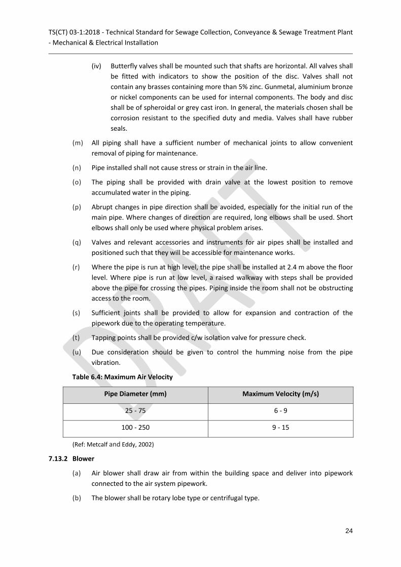
Table 6.4: Maximum Air Velocity
Pipe Diameter (mm) Maximum Velocity (m/s)
25 - 75 6 - 9
100 - 250 9 - 15
(Ref: Metcalf and Eddy, 2002)
7.13.2 Blower
(a) Air blower shall draw air from within the building space and deliver into pipework
connected to the air system pipework.
(b) The blower shall be rotary lobe type or centrifugal type.

TS(CT) 03-1:2018 - Technical Standard for Sewage Collection, Conveyance & Sewage Treatment Plant
- Mechanical & Electrical Installation
25
(c) Rotary lobe blower (surface) used in the STP shall incorporate as a minimum
requirement the following:
(i) Three lobes type.
(ii) Air inlet filter and silencer.
(iii) Compressed air discharge silencer, complete with isolating valve, non-return
valve, pressure relief valve (safety valve) and pressure gauge.
(iv) Flexible connections.
(v) Vibration absorber shall be provided as a standard feature; neoprene rubber for
blower less than 15 kW, spring loaded vibration isolator shall be provided for
blower 15 kW and above.
(d) The centrifugal blower type is used for medium and large air capacity requirements.
The basic requirement for centrifugal blower used for aeration in STP are as follows:
(i) Electrical starter, which shall be 3 Phase, 400 Volt, 50 Hz, permanent magnet
synchronous motor (PMSM) incorporated with variable speed drive (VSD), HMI,
power meter.
(ii) Type of installation: Enclosed type, indoor.
(iii) Cooling system: Forced air cooling or water coolant
(iv) Turbo compressor type: Magnetic bearing and air bearing type only.
(e) Pressure relief valves shall be capable of discharging the maximum air flow rate
delivered by the blower. The valves shall be installed downstream of non-return valves
and as close as possible to the blower delivery flange.
(f) The pressure gauge shall be silicon filled, fitted with snubber and shall be provided
with isolating cock.
(g) The blower noise level shall be less than 85 dB(A) consistency when measured at 1 m
from any point of the blower.
(h) The complete assembled air blowers are mounted on a common base frame for
placing onto concrete plinths.
(i) The blower shall be installed in a sufficiently lighted and ventilated room or building.
(j) Air blower room shall be large enough to accommodate air blower unit and its
accessories with sufficient working space all round. Minimum clearance of 600 mm
(end to end) shall be provided between the air blower and side walls and all-round the
blower to provide sufficient space for periodic inspection and maintenance of the air
blower and its accessories.
(k) Sufficient forced ventilation shall be provided to maintain the air blower room
temperature at no more than 40°C.

TS(CT) 03-1:2018 - Technical Standard for Sewage Collection, Conveyance & Sewage Treatment Plant
- Mechanical & Electrical Installation
26
(l) Access door of the air blower room shall be sized 400 mm larger than air blower
physical dimensions to cater for removal of air blower unit into and from the room
without obstruction.
(m) Appropriate lifting facilities (section 7.19) provided in the air blower room for handling
purposes during maintenance and replacement works.
(n) Concrete plinth shall be of sufficient mass to provide a solid and firm support for the
base frame of the complete assembled blower units. The concrete for plinth
construction shall be to grade C30. The size of the plinth shall be a minimum 100 mm
clearance all-round the base frame. Height of the plinth shall be minimum 100 mm
from the floor. The top surface of concrete plinth shall be finished flat and smooth.
7.13.3 Guarding of Air Pipes at Blowers
(a) Flexible joint shall be installed between the blower and the piping.
(b) Any exposed pipework, valves and fittings that could be subjected to a surface
temperature greater than 50°C under any normal operating condition shall be guarded
to prevent human contact.
(c) The guarding shall comprise cages of open mesh type panels supported in framework
fixed to the floor.
(d) Panels and framework shall be removable for access and maintenance of pipework
fittings. All guard materials shall be positioned at a suitable distance from hot
pipework surfaces to avoid their surfaces exceeding 50°C. Guard materials shall be
corrosion resistant and have sufficient rigidity for this application.
7.13.4 Diffuser System for Aeration Tank
(a) Each diffuser shall have a fixed control orifice to regulate the air supply and assist in
providing an even distribution over the tank surface.
(b) Diffuser shall be spaced symmetrically in a grid pattern in each tank to provide even
and complete mixing throughout the tank.
(c) Provide sufficient supports and allowance for expansion, contraction, thrust, uplift,
etc. and all forces to be encountered in this operation and at the depth of water
expected. There shall be a minimum clearance of 150 mm between the bottom of the
floor pipes and the tank floor.
7.13.5 Diffuser System for Aerated Grit and Grease Chamber, Equalization Tank and Sludge
Holding Tank
Provide sufficient supports and allowance for expansion, contraction, thrust, uplift, etc. and
all forces to be encountered in this operation and at the depth of water expected. There
shall be a minimum clearance of 150 mm between the bottom of the floor pipes and the
tank floor.

TS(CT) 03-1:2018 - Technical Standard for Sewage Collection, Conveyance & Sewage Treatment Plant
- Mechanical & Electrical Installation
27
7.14 Mixers
(a) Mixers shall be used for liquid mixing application for homogenisation and suspension
of liquids to avoid formation of surface crusts and bottom deposits.
(b) The submersible mixer shall be capable of continuous operation under submergence
condition and shall be mounted on a guide rail system. Minimum submergence
requirement for submersible mixer shall be maintained. The submersible mixers shall
be installed as follows:
(i) Mixers shall be placed appropriately from wall and floor in order to avoid vortex
formation during operation.
(ii) If the mixers to be installed at a fixed point in the tank, a vibration rubber
damper shall be provided to avoid excessive vibration of the mixer. Safety stop
shall be provided to prevent over travel of the mixer during hoisting down to its
intended position.
(iii) Cable clamp complete with cable hook shall be provided at the deck level for
securing cable from being caught up in the mixer propeller.
(iv) The guide rail system shall be provided to allow the mixer to slide down to its
intended position by means of a sliding bracket. A lifting davit with manual hoist
shall be provided for lifting and lowering the mixer. Refer to Section 7.18 on
lifting facility) The whole system shall permit the working angle of the mixer to
be adjusted horizontally and vertically and full adjustment of the depth and
direction of the mixer.
(v) Hoisting rope attached to the mixer shall be parallel to the lifting davit position
so that the mixer can slide freely on the guide rail.
(vi) The guide rail shall be strong enough to avoid deformation under the forces
created by the submersible mixer running under designed load conditions.
Maximum deflection allowed is 3 mm.
(vii) The guide rail shall be provided with bottom footing for anchoring onto the tank
floor. For a long guide rail, stainless steel wall brackets shall be provided at 2 m
interval for mounting guide rail to the tank wall to avoid deflection of guide rail.
7.15 Scraper
(a) Proper scrapers shall be installed to the clarifiers and shall comprise of sludge
collector and skimming equipment, complete and operable as required.
(b) The scrapers shall be suitable for the circular or rectangular clarifiers.
(c) For circular clarifier, peripheral driven scraper shall be provided with peripheral feed
and centre overflow weir for the effluent.
(d) The scraper for the rectangular clarifier shall comprise of a horizontal bridge travelling
sludge collector or a multiple travelling solid collector, c/w a drive motor and chain to
facilitate horizontal movement of the bridge.

TS(CT) 03-1:2018 - Technical Standard for Sewage Collection, Conveyance & Sewage Treatment Plant
- Mechanical & Electrical Installation
28
(e) The circular scraper shall be installed as follows:
(i) Tank dimensions and gradient of the floor shall be verified before commencing
installation of the scraper. The tank shape irregularities shall be identified.
(ii) True centre of the tank shall be established and the diameter of this circle
checked for proper functioning of the scraper. Remedial works on the concrete
tank shall be carried out if necessary by hacking, grinding off protruding wall
and plastering up areas with insufficient concrete.
(iii) The central column of the tank shall be in the centre and level with the
surrounding perimeter.
(iv) Prior to the installation of thrust bearing, at least 10 points shall be taken all
round the perimeter and the distance measured from the centre of the tank.
The thrust bearing shall be shifted until the distances are all the same.
(v) The girder of the bridge crane shall be hooked at 2 points to lift and then placed
to one side near the tank.
(vi) The scraper components shall be positioned and joined inside the tank.
(vii) After checking alignments, the couplings of the scrapers shall be connected in
descending ways.
(f) The installation of bridge travelling sludge scrapper shall be as follow:
(i) Upon verification of tank dimension typically to tolerances of ± 20 mm, the
bridge and other components shall be hooked by a crane and lowered on the
surface.
(ii) The bridge shall be temporarily lifted by a crane, to remove the pipe that holds
the connecting shaft and the four strike wheels (guard wheels).
(iii) The shafts, the O rings and the blocking nuts shall be connected to the pipe that
holds the connecting shaft.
(iv) The bridge crane shall be raised, taking care to turn the translating gear motor
towards the sludge collection trough and keeping the connecting shafts on the
opposite side.
(v) The bridge crane sliding wheels shall be checked and adjusted to make sure
they are parallel to the walls. A point along the whole length of the tank at
which the distance between the walls is shortest shall be found using a
theodolite. The bridge crane shall be taken to this point, so that all adjustments
shall be carried out at the tightest point of the tank.
(vi) The previously removed strike wheels (guide wheels) shall be assembled and
adjusted so that all four wheels are leaning against the wall. The strike wheels
shall be fixed using the supplied bolts when the bridge crane is perpendicular to
the walls.

TS(CT) 03-1:2018 - Technical Standard for Sewage Collection, Conveyance & Sewage Treatment Plant
- Mechanical & Electrical Installation
29
(vii) The scraper boom, frame and scraper shall be assembled in the tank and
attached to the shaft by transoms.
(viii) The bottom scrapers shall be inserted into the tank and positioned so that the
sliding wheels face the side opposite the sludge collection trough. Using the
adjustable attachments, the shafts shall be fixed to the bottom scrapers.
(ix) The cable winders for surface frame and the bottom scraper transom shall be
installed.
(x) The rails shall be installed at the same level on top of both sides of the tank
walls in the longitudinal direction. Checks shall be made at least 5 points
along the rail tracks to ensure that the distance between the rails on both
sides of the tank is kept constant within the tolerances of the wheels,
typically ± 20 mm.
7.16 SBR Effluent Decanter
(a) The decanters shall be installed and supervised by a technical person.
(b) The types of decanters include surface skimming, floating, fixed-pipe and siphon.
(c) The surface skimming decanter for withdrawing the uppermost supernatant from the
reactor basin shall consist of a decanting trough complete with an integral floating
scum baffle / guard, decanting down pipes, effluent discharge pipe, rotating joint,
hydraulic seal and bearing assemblies, extension rod and driving unit. The driving unit
shall consist of electric motor with a gear reducer or Direct driven with variable speed
drive (VSD).
(d) The floating decanter assembly for removing an upper fluid layer from a reactor basin
shall comprise of:
(i) The float and mooring cables where applicable.
(ii) A discharge conduit (or flexible hose) connected to the float having a liquid
receiving opening surrounded by a flange; the float maintaining the opening at
a generally constant depth relative to the upper fluid level in the reactor basin.
(iii) Electrically-actuated valve assembly attached to the outlet of the discharge
pipe.
(e) The fixed-pipe decanter is attached to the reactor basin wall to the bottom water level
elevation and the draw- off level is fixed.
(f) The siphon decanter shall consist of a horizontally supported pipe with suction nozzles
or inverted weirs. The pipe shall be connected to a discharge pipe via a U-shaped pipe
arrangement and complete with a siphon valve located at the top of the vertical pipe.
7.17 Sludge Thickener
The requirements for picket fence gravity thickener (PFT) are as follows:
(a) The PFT mechanism shall be hot-dipped galvanized.

TS(CT) 03-1:2018 - Technical Standard for Sewage Collection, Conveyance & Sewage Treatment Plant
- Mechanical & Electrical Installation
30
(b) PFT shall rotate from the bridge supported by a steady bearing at the bottom.
(c) The gear-motor shall be fitted with a mechanical torque limiter. It shall be epoxy
coated for protection against corrosion.
(d) The centre shaft shall be directly coupled and driven by the drive unit system.
The centre shall be made with tubular design and the shaft’s lower part is equipped
with a replaceable bottom bearing made of durable material, which operates against a
steel stub shaft.
(e) The central tube horizontal scraper arms with angled scraper blades shall be fitted for
bottom scraping to remove sludge from the entire floor to the sludge pit in the centre
of the tank.
7.18 Lifting Facility
(a) The NPS and STP shall be provided with suitable lifting facilities for lifting pumps,
blowers and other equipment for maintenance. Refer to Table 6.5 for the
requirements of the lifting facility.
(b) The lifting facilities shall be in accordance with DOSH regulations. The safe working
load (SWL) as well as the safe lifting height of the lifting facility shall be clearly marked
on the label of the lifting facility.
(c) The SWL of the lifting facility shall be 20 % greater than the individual weight of
the heaviest equipment or parts to be handled.
(d) The lifting facility shall conform to BS EN 13001-1:2015 Class 2 ‘medium duty’ and
meet the specified operational requirements. Runway rails for the hoist shall be
constructed from structural steel I-beam.
(e) Lifting hooks shall be safety hooks made from Grade 30 carbon steel and capable
of swivelling through 360 degrees.
(f) An identification plate shall be provided on all hoists indicating the manufacturer's
name, SWL, serial number, BS number and year of manufacture.
(g) Height and lifting method must be considered in the design of SWL for lifting
facilities.
(h) All portable motorised hoist shall be rated 240 V operating voltage and fixed
electrical hoist shall be rated 400 V operating voltage.
(i) All fixed 3-axis type gantries shall come with additional safety features such as travel
stop limit switch, hoist over run limit switch, slow and fast speed mode and
emergency stop (for all type of hoist).
(j) All fixed type outdoor lifting facility shall comprise of hoist parking bay with shade.
(k) All fixed type lifting facility shall come with working platform and access ladder.
(l) The requirements of the electric hoist are as follows:

TS(CT) 03-1:2018 - Technical Standard for Sewage Collection, Conveyance & Sewage Treatment Plant
- Mechanical & Electrical Installation
31
(i) For electrically operated hoists, the drive motors shall be fitted with an
automatic electromagnetic break to prevent over travel of the hoist on
interruption of the power supply.
(ii) Safety disc brakes shall be incorporated to hold the suspended load instantly,
securely and automatically, in the event of the current being cut off. Facilities
for override for the disc brake for hand release of the load shall be
incorporated.
(iii) Means of manoeuvring hoists manually from the floor shall be provided for use
in the event of a power failure.
(iv) Power feed to the electric hoist shall be through a close looped flexible cable
catenary suspension system with carriers sliding along a track along the full
length of the building.
(v) All hoist functions shall be controlled from a single pendant unit. The pendant
unit shall be suspended using a non-metallic cord and not the control cable. The
pendant shall operate from a low-voltage source, incorporate a key-operated
switch to prevent unauthorised operation and indicators to indicate all hoist
movements. Interlocks shall be provided to prevent simultaneous lift and travel.
(vi) Limit switches to cut-off the raising and lowering motion when the hook
reaches its maximum limit of travel shall be provided.
(m) The requirements of the manual hoist are as follows:
(i) Manually operated chain hoists shall be arranged for close lift with two falls to
the lifting hook and geared travel.
(ii) The load chain shall be of alloy steel Grade 80 and the hand chains shall be mild
steel. The load chain wheel shall have pockets and a chain guide to align the
chain with pockets to prevent the chain from jumping off the wheel.
(iii) Hoist units shall incorporate a brake which shall be applied automatically when
effort on the hand chain is released. The applied brake load shall be
proportional to the load on the hook.
Table 6.5: Requirements of Lifting Facility
Item Description Requirement
1. Manual lifting davit Lifting weight < 16 kg
2. Manual lifting hoist 16 kg ≤ Lifting weight < 100 kg
Provide A-frame or I-beam. Manual hoist and lifting chain for
the wet well, at least 2 m above the access road level.
Provide I-beam with proper support, manual hoist and lifting
chain for the blower room, at least 2.2 m above the access

TS(CT) 03-1:2018 - Technical Standard for Sewage Collection, Conveyance & Sewage Treatment Plant
- Mechanical & Electrical Installation
32
Item Description Requirement
road level.
The I-beam to project 1.2m outside the building / structure.
3. Motorised lifting hoist Lifting weight ≥ 100 kg
Provide A-frame or I-beam, motorised hoist and lifting chain
for wet well, at least 2 m above the access road level.
Provide I-beam with proper support, motorised hoist and
lifting chain for the blower room, at least 2.2 m above the
access road level.
The motorised hoist to be provided with galvanised chain and
movable controls for the hoist motor.
The I-beam to project 1.2 m outside the building / structure.
4. Lifting chain Minimum 6 mm diameter long link smooth welded complete
with fixings including ‘S’ hooks and ‘D’ shackles stainless steel,
come with stainless steel rings at every 1m interval.
7.19 Fire Protection System
(a) The NPS and STP shall be provided with proper facilities for fire safety, in compliance
with the latest version of relevant fire regulations.
(b) The facilities provided shall include but not limited to portable fire extinguishers: CO2
type for electrical control room and dry powder type for other areas.
8.0 Electrical Installation
8.1 Power Supply System
Power supply to STP shall be provided in accordance with the relevant statutory regulations
and as follows:
(a) A single incoming power supply system shall require design control overflow during
power failure. All electrical control system shall be located above design flood level.
(b) The power system distribution shall be designed to achieve a power factor of not less
than 0.85. For phase development, the plant and power system distribution shall be
designed for maximum load and installed in appropriate modular unit to ensure that
the minimum power factor is achievable at all phases of operation. Capacitor bank
shall be provided to ensure the power factor more than 0.85.
(c) No direct tapping of power is allowed from distribution board (DB). Proper protection
shall be provided for any direct connection from switchboard. Residual current device
(RCD) with minimum sensitivity of 30 mA shall be provided for socket outlet and 100
mA for lighting. An earth leakage relay (ELR) (above 100 A) shall be provided for DB.

TS(CT) 03-1:2018 - Technical Standard for Sewage Collection, Conveyance & Sewage Treatment Plant
- Mechanical & Electrical Installation
33
(d) Where an early warning system (EWS) is provided, the essential parameters are to be
monitored during power supply interruptions. The EWS shall be provided with a DC
supply or a uninterrupted power supply (UPS). Batteries / UPS shall have the capacity
to operate the EWS for a minimum 8 hrs during power failure to safe last event, to
monitor the essential parameters and to enable EWS.
(e) Equipment shall be protected by either moulded case circuit breaker (MCCB) or
miniature circuit breaker (MCB) based on its suitability. Every control circuit shall be
protected with separate MCB.
(f) TNB meter panels shall be installed adjacent to the site entrance and physically
separated from the main switchboard. Suitable flexible steel conduit with adaptors
shall be supplied and fitted between the main switchboards.
(g) All metering panel shall be located flush with the fence and door opening from outside
to enable TNB inspector to read the kWh and kVAh reading.
(h) Where the total power is more than 100 A, earthing connected with Current
Transformer (CT) shall be provided.
(i) Earthing connected to Earth Leakage Circuit Breaker (ELCB) / Residual Current Circuit
Breaker (RCCB) / ELR or over current and earth fault relay to protect overcurrent and
surge current to all wiring connected to TNB metering panel shall be provided.
Earthing system shall be below or equal 1 ohm.
8.2 Switchboards and Control Panels
(a) Switchboards, sub-switchboards, control panels, distribution board and all other
equipment shall comply with the relevant current statutory regulations, Malaysian
Standard and IEC specifications.
(b) Main switchboard shall be equipped with automatic power factor correction with
capacitor rated at 525 V to ensure minimum of 0.85 power factor is maintained all the
time. Detuned reactor shall be provided to suppress harmonics due to equipment
such as variable speed drive, etc. Digital power meter (DPM) shall be installed at the
main switchboard for energy and power quality monitoring. Main supply bus bars
shall extend the full length of panels and the panel casings shall be effectively earthed.
(c) Control panels rated ≤ 100 A shall be wall mounted and rated > 100 A shall be floor
mounted.
(d) Floor mounted cabinets to have a minimum 50 mm high base frame and the total
height of the cabinet shall not be greater than 2 m. Floor mounted panel shall be
mounted on minimum 100 mm reinforced concrete plinth, above the finished floor
level.
(e) Total height of the wall mounted cabinets shall be not greater than 1.6 m. Wall
mounted cabinet shall be mounted on minimum clearance of 300 mm above the
finished floor level.

TS(CT) 03-1:2018 - Technical Standard for Sewage Collection, Conveyance & Sewage Treatment Plant
- Mechanical & Electrical Installation
34
(f) Each item shall be enclosed in a vermin proof steel cubicle of rigid construction and
made of sheet steel of such thickness that it is free from distortion and with no
entries for insect whatsoever. Where two or more cubicles are fitted together they
shall form a continuous flush front.
(g) The door of the switchboard shall be hinged such that they can be operated
through an arc of 180 degrees. A minimum of 3 hinges shall be chrome-plated and of
good quality.
(h) All switchboards, together with switch gears, control gears, etc. shall be capable of
withstanding fault conditions of not less than 31.5 kA at 400 V for 3 seconds and of
Form 3B as stipulated in IEC 61439-2.
(i) The cubicle framework shall be fabricated from rolled steel angle sections and shall
be self-supporting when assembled, uniform in height and depth from front to back.
The rigid construction shall be designed to withstand without any sag,
deformation or warping, the loads likely to be experienced during normal
operating, maintenance or maximum fault conditions. Cross-struts shall not be used.
(j) The cubicle and junction box shall be made of electro-galvanised steel sheets of
thickness not less than 2.5 mm for the frame, 2 mm for the plate and minimum
ingress protection (IP) of 54 (indoor installation) and 65 (outdoor installation), finished
with 300 micron thick light grey powder coated paint (Par willow grey 00A05). It shall
be treated to prevent corrosion.
(k) For outdoor installation subjected to corrosive environment, electrical switchboard,
feeder pillar and junction box shall be made of stainless steel. Additionally, junction
box shall be water-tight, dust and damp proof.
(l) The interior of each piece of equipment shall be clearly marked to show phases and
coloured plastic sleeving shall be employed. Plastic tape will not be permitted.
Steelwork necessary for supporting the switchboards shall also be included.
8.3 Motors, Controllers and Motor Starters
(a) All motors, controllers and motor starters must provide readily replaceable anti-
condensation heaters.
(b) Electrical motors should be rated as continuous run and provided with at least three
thermistors for all motors. In addition, the motors > 22 kW shall be protected with
VSD.
(c) Where water hammer prevails, frequency inverter shall be provided.
(d) Switchboard that experience heating shall be provided with appropriate cooling
system based on the requirements of the switchboard.
(e) The switchboards and control panels shall include green coloured and recessed ‘Start’
push buttons, recessed red coloured ‘Stop’ push button, red coloured mushroom head
type push button for ‘Emergency stop’, green coloured ‘On’ signal lamp, red coloured
‘Off’ signal lamp and amber coloured ‘Trip’ signal lamps.

TS(CT) 03-1:2018 - Technical Standard for Sewage Collection, Conveyance & Sewage Treatment Plant
- Mechanical & Electrical Installation
35
(f) Motor starters shall be in accordance with MS IEC 60947-1:2010 and MS IEC 60947-4-
1:2005 and equipped with overload and no volt protection. Where Motor Control
Centre (MCC) are supplied as a standalone unit, it shall comply with the switchboard
specification. Single phase and earth leakage protection shall be deemed to be
included. Starters shall be of the contactor type with coils wound for 240 Volts 50
cycles operation.
(g) All starters shall be capable of at least 15 starts per hour at 100 % full load torque. The
motor starter shall be of rating to carry the full load current of its rated duty at its
most severe load conditions.
(h) All motor starters shall be provided with auto restart facility as well as automatic and
manual control type with “Start / Stop / Reset" facility, MCCB mechanically inter-
lockable with access door, independent control circuit with fuses / MCB and provision
for remote control as required.
(i) Individual starters shall be provided for each equipment and housed in a separate
compartment, which are mounted in switchboard cubicles. The starter cubicles shall
be easily accessible for maintenance purpose constructed of IP 42. Unless otherwise
approved, the metal surface of the cubicle wall adjacent to the contactors shall be
protected by fireproof insulating material. All secondary wiring shall be so arranged
and protected as to prevent it from being damaged by arcing. Where draw-out
patterns motor starter is specified, the starter shall be easily withdrawable and can be
replaced with another spare starter of similar rating.
(j) Controllers shall be provided as follows:
(i) Up to 3.7 kW, provide direct-on-line (DOL) starters.
(ii) Above 3.7 and up to 7.5 kW, provide star / delta starters.
(iii) Above 7.5kW, provide soft starters.
(iv) More than 22 kW, provide VSD.
(k) For DOL starters, an air-break tri-pole electromagnetic contactor starter with a normal
open retaining auxiliary contact, shall be provided. The auxiliary contact shall be c/w
one closing / holding coil 240 V, 50 Hz (no-volt coil inherent) and Electronic Over /
Current Relay (EO / CR) with resetting devices and auxiliary signal lamp contact. The
reset push button shall be accessible from outside.
(l) For star delta starters, an air-break triple pole electromagnetic ‘LINE’ contactor fitted
with necessary auxiliary contacts, closing / holding coil, EO / CR, etc. shall be provided.
The EO / CR shall be connected in the delta position and thus give automatic single-
phase protection. The starter shall contain an air break triple pole and neutral ‘STAR’
contactor fitted with the necessary auxiliary contacts and an air break triple pole and
neutral ‘DELTA’ contactor fitted with the necessary auxiliary contacts. The star delta
contactors shall be electrically and mechanically interlocked. The starter shall be c/w
necessary time delay contacts to effect the correct sequence of operation.

TS(CT) 03-1:2018 - Technical Standard for Sewage Collection, Conveyance & Sewage Treatment Plant
- Mechanical & Electrical Installation
36
(m) The soft starter shall include an electronic controlled reduced starting facility capable
of smoothly accelerating the pump set motor and its load to full speed without step
changes in motor torque during the acceleration period. The soft starter shall have a
smooth stopping facility which can be selected to give a progressive reduction in
voltage applied over a period, following the initiation of a stop command. A step-
down facility for voltage, adjustable between 100 % to 30 % shall be included for soft
stop. The unit shall be provided with an electronic overload protection as standard.
This overload shall be possible to remote reset and a separate signal relay detecting
an overload separated from other faults. A separate temperature sensor mounted on
the heat sink for detecting high ambient temperature or ineffective cooling shall be
provided.
(n) The VSD unit shall be provided with the following protection functions:
(i) Over / under voltage controller.
(ii) Motor short-circuit protection.
(iii) Input phase-loss detection (both motor and line).
(iv) Overcurrent protection.
(v) Drive temperature / overload controller.
(vi) Power limits motor thermal protection.
(o) Sufficient mechanical ventilation shall be designed and provided for the VSD for the
direct extraction of heat to the external of the room to avoid hot air circulation within
the room. This is to ensure no break down during the operation due to overheat.
Other cooling system can be considered as option when needed.
(p) The alternating current (AC) drives shall operate with an input power factor not less
than 0.85 throughout the speed range.
(q) Motor protection relays shall have overload, single phasing and earth fault protection
schemes and can be set over suitable ranges. Output terminal for remote monitoring
of relay status shall be provided.
(r) Electronic motor protection relay shall be used for motor rating exceeding 100 kW.
(s) The electronic motor protection relay shall perform thermal overload protection,
thermal start up supervision, jam protection / time overcurrent protection, high set
overcurrent, low set earth fault protection, phase reversal, phase unbalance, loss of
load protection and supervision of multiple start-ups.
(t) Thermistor relay which may be separate or incorporated as another feature of the
electronic motor protection relay shall be provided to trip the motor on overheating
of the windings.

TS(CT) 03-1:2018 - Technical Standard for Sewage Collection, Conveyance & Sewage Treatment Plant
- Mechanical & Electrical Installation
37
8.4 Control and Instrumentation
8.4.1 Programmable Logic Controller (PLC)
(a) The NPS and STP shall be provided with the required instrumentation comprising of
Programmable Logic Controller (PLC), signal cabling and etc., to ensure that the
facilities are performing in accordance with the design requirements.
(b) The PLC shall be complete with touch screen display such as Human-Machine
Interface (HMI).
(c) As a minimum, the PLC system shall be provided with the following performance
capabilities and features:
(i) The PLC shall be provided with back-up power supply such as uninterruptible
power supply (UPS), to ensure program memory (i.e., process control program,
last-known set points and measured process / equipment status) are retained in
case of a power failure.
(ii) Backup processor (CPU) for PLC shall be provided to ensure rapid process
recovery or minimise the deterioration of effluent quality in the event of the
duty PLC out of order.
(iii) Individual MCCB shall be provided of for isolation purpose. Both duty and
backup PLC system control shall allow independent operation of each tank.
(iv) Failsafe control shall be provided which will not allow the operator to adjust the
settling phase duration to less than 30 mins.
(v) Provide effective process control by integrating the instruments and main
components to optimize system performance and at the same time complying
with effluent quality standards.
(vi) Prevent interruption of operation due to unexpected event such as high flow,
equipment failure etc.
(vii) PLC control shall be programmed to consider the followings:
• Ability to adjust the operation sequence and period.
• Ability to initiate EWS.
• Ability to handle expected flowrate variations.
• Ability to monitor, control and record event occurrence.
• Ability to vary the airflow based on process demand.
8.4.2 Instrumentation
(a) The instrumentations shall be installed in such a way that they can be removed for
maintenance without interrupting the process.
(b) All parameters measured as mentioned must be retrievable at all time.

TS(CT) 03-1:2018 - Technical Standard for Sewage Collection, Conveyance & Sewage Treatment Plant
- Mechanical & Electrical Installation
38
(c) The instrument meters shall be connected to the equipment and ancillary required
using separate cables for digital and analog signals.
(d) Refer to Table 6.6 for the requirement of the process instrumentation.
Table 6 . 6 : Process Instrumentation Required
Location Instrumentation for Monitoring
Network pumping station
(NPS)
• Pump operations (Water level)
• Gas detector for H2S and CO2 (For enclosed plant)
Inlet pump station, STP • Pump operations (Water level)
• Gas detector for H2S and CO2 (For enclosed plant)
Before secondary screen
and after wet well, STP
• Flow meter
Aeration tank, STP • DO
• Level sensor (SBR)
Decanter (SBR), STP • Position indicator and speed
After chlorination chamber,
STP
• Flow meter
Electrical main switchboard,
STP
• Meters for running amp / volt / hours run / kW / power
factor
8.4.2.1 Level Controls
Requirements for level controls shall be as follows:
(a) The level controls shall be used for the control of pump operations, that is, the start
and stop of pumps. The control shall be either floats, electrodes, ultrasonic level
controls, non-ceramic pressure transducer.
(b) Only non-mercury type floats are allowed.
(c) Hollow tube electrodes are not acceptable.
(d) Level controls shall be placed where they are not affected by the turbulence of
incoming flow and where they can be safely removed.
(e) When float switch are used, cable hanger shall be installed and minimum distance of
150 mm between floats.
(f) The requirements of the float switch are as follows:
• Contact system : Micro switch
• Output : Changeover contact
• Maximum load : 10(8)A 250V – 10(4)A 380V

TS(CT) 03-1:2018 - Technical Standard for Sewage Collection, Conveyance & Sewage Treatment Plant
- Mechanical & Electrical Installation
39
• Frequency : 50 – 60 Hz
• Maximum voltage : 250 V AC
• Temperature : 0o C – 70o C
• Dimension : 165 mm (L) x 100 mm (Diameter)
• Housing material : Polypropylene
• Cable material : HO5RN‐F3 ‐ 0.75 mm2
(g) The requirements of the pressure sensors are as follows:
• Supply : 6 VDC – 27 VDC
• Output : 4-20 mA
• Calibration accuracy, including non-linearly, hysteresis and repeatability
: < ±0.35%
• Ambient temperature : -20⁰C – 80⁰C (-4⁰F – 176⁰F)
• Media temperature : Maximum 80⁰C (176⁰F)
• Electromagnetic compatibility based on (EMC) 2014/30/EU
: EN 61326-1, EN 61326-2, EN 61326-3
(h) The requirements of the ultrasonic level sensor are as follows:
• Range : 10 ft. (fluids), 4 ft. (solids)
• Frequency : 75 kHz
• Spread : 7°
• Dead band : 14"
• Temperature : - 20 °C to + 65 °C
• Materials : Power bed fusion (PBF) / ceramic
8.4.2.2 Flow meter
Flow measurements shall be made by using ultrasonic flow meters or electromagnetic flow
meters as set out in Table 6.7.
Table 6.7: Requirements of the Flow Meter
No. Description Requirement
1. Overall (a) Power supply: 240 AC 50Hz
(b) Operating temperature: 20-60 degree Celsius
(c) Accuracy: +/-0.2% of set measuring range
(d) Displays flow rate in l/s or m3/h
(e) Displayed value: Flow rate, total flow, date, time, total hour,

TS(CT) 03-1:2018 - Technical Standard for Sewage Collection, Conveyance & Sewage Treatment Plant
- Mechanical & Electrical Installation
40
No. Description Requirement
temperature.
(f) To be installed with flow meter transmitter / controller and data
logger / chart recorder.
(g) Outdoor weatherproof pedestal panel and housing shall be
provided.
(h) The instrumentation cable must be arranged neatly and fully
enclosed. Overhang cable is not allowed at any closing.
(i) The connection between the device and the cable must be tight
compile. Intermediate jointing of instrumentation cable between
sensor and control panel is not permitted.
(j) To provide electrical / wiring diagram.
(k) Language: English
2. Ultrasonic
sensor
(a) Flow meter shall have minimum IP 68 protected c/w 5m
minimum length of sensor cable.
(b) An integrated temperature sensor shall compensate for changes
in the velocity of sound caused by temperature changes.
(c) Material: Minimum Polyvinylidene Fluoride (PVDF) and Ethylene
Propylene-Diene monomer (EPPDM) (as the sealant).
3. Electromagnetic
flow meter
(a) Flow meter shall have minimum IP 67 protection.
(b) Preferred display: LCD or LED digital format.
(c) All installations must comply with the following:
(i) An isolating valve must be installed upstream of the meter
for maintenance purposes.
(ii) Pipework in and out of the flow meter must ensure that the
flow meter section remains full at all times.
(iii) Avoid installing the flow meter near strong electromagnetic
fields.
4. Transmitter /
controller
(a) Flow meter transmitter shall have minimum IP 65 protected and
completely microprocessor controlled.
(b) All inputs and outputs shall be galvanically isolated from power
supply up to 500 V and isolated from each other.
(c) Digital output and communication port shall be minimum of
RS485.

TS(CT) 03-1:2018 - Technical Standard for Sewage Collection, Conveyance & Sewage Treatment Plant
- Mechanical & Electrical Installation
41
No. Description Requirement
(d) Freely selectable output damping of 0 to 255 seconds.
(e) Display backlight / energy saving.
5. Totalizer 8-digit accumulative with programmable multiplier: x1, x10, x100,
x1000, 31 daily, 8 digit totalizers.
6. Data logger (a) User shall be able to configure data logging interval set up. The
device shall be able to capture as listed:
(i) Average flow
(ii) Minimum flow
(iii) Maximum flow
(iv) Total flow
(b) Storage of various data rate for up to two (2) months with record
data for real time.
(c) Data logger shall be supported by USB port to enable data
downloading to external storage directly from the data logger at
site.
(d) The device shall have the capability to continuously store data for
a minimum of four (4) hour in the event of power failure.
(e) Device shall be able to transmit data to modem.
7. Control panel
and housing
(a) Control panel shall be pedestal type panel to mount flow
transmitter, data logger, modem and electrical components.
Requirement for the panel and the housing shall be as below:
(i) Material: Mild steel
(ii) Panel thickness: Minimum 2.3 mm
(iii) Paint / coating thickness: minimum 90 µm
(iv) Paint / coating colour code: Par willow grey 00A05
(v) Panel shall be minimum IP 65 protected
(b) The control panel shall be enclosed in a housing provide with
locking mechanism by handle with key and without viewing
panel.
(c) Outdoor panel shall be placed on a concrete slab with a minimum
of 100 mm height.
(d) All panel shall be erected on properly design footing.
(e) Shelter is required for ultrasonic transmitter that is not installed

TS(CT) 03-1:2018 - Technical Standard for Sewage Collection, Conveyance & Sewage Treatment Plant
- Mechanical & Electrical Installation
42
No. Description Requirement
inside at the panel and expose to weather.
8. Modem Global System for Mobile Communication (GSM) / General Packet
Radio Service (GPRS) / 3G / Latest version Modem
8.5
8.5 General Lighting and Power
(a) All light fittings and other electrical installation for building should comply with MS IEC
60364 and Electrical Installation Regulations issued by Suruhanjaya Tenaga.
(b) The light fittings shall be finally positioned in the ceilings in accordance with any
ceiling grid layout and size, with the relative position and size of other services,
structural beams and obstructions or other factors which may influence the light
fittings position.
(c) Ensure that all the light fittings and outlets are in accordance with the relative
positions of the other services.
(d) Each surface mounted light fitting shall terminate at a junction box c/w porcelain
connectors suitable for the size and number of connections to be made at that point
and the wiring required connecting the specified fitting. All lighting points and
switches shall be earthed with its appropriate earth continuity conductor according to
the MS IEC 60364.
(e) For recessed mounted light fitting, a flexible steel conduit shall be provided from a
junction box to the fitting. Especially in the case of down lights, no exposed wiring
shall be seen at the light fitting end.
(f) The indoor lighting shall be of LED type with minimum 50,000 hour burning hour. The
LED light fitting shall be equipped with high frequency electronic ballast installation,
the operating frequency range shall be between 20 kHz to 40 kHz.
(g) All light fittings shall be suitable for operation at 240 V single phase, 50 Hz supply.
(h) The reflector shall be of one-piece construction made from quality electro-galvanised
sheet steel of 0.8 mm and the main housing shall be of 1 mm thick with epoxy powder
coated paint.
(i) The entire metal reflector shall be specially treated to prevent rust and corrosion and
finished with 2 coats of white paint.
8.6 Self-Contained Emergency and KELUAR Lighting Luminaries
(a) Each unit shall have a sealed heavy-duty nickel cadmium battery, a constant current
charger, a silicon transistor inverter with a solid-state changeover circuit and a 15 W
LED and be maintenance free. The unit shall be mounted in a metal housing stove
enamelled to BS EN 60598-2-22:2014 and with prismatic diffuser. The unit shall be
provided with a mains healthy light emitting diode, indicator and a test button to
simulate mains failure. In the event of mains failure, it shall be able to provide a

TS(CT) 03-1:2018 - Technical Standard for Sewage Collection, Conveyance & Sewage Treatment Plant
- Mechanical & Electrical Installation
43
minimum of 3 hours emergency lighting after a 12 hours recharging. All self-contained
emergency lighting luminaries shall be of types approved for use by the Jabatan
Bomba dan Penyelamat Malaysia (JBPM) and Suruhanjaya Tenaga (ST).
(b) KELUAR luminaries shall also comply with MS 983:2004 and their locations determined
by JBPM.
8.7 Switches
(a) Light switches shall be rated at 10 Amp. The location of switches shall be determined
after due consideration of size and opening direction of doors, other services, etc.
(b) Light switches shall not be placed at the junction of different finished or on
demountable partitions. They shall be mounted 1.5 m above finished floor.
(c) Light switches controlling weatherproof or corrosion proof lighting fittings shall be
weatherproof or corrosion proof type.
8.8 Timer Switches and Contactors
All timer switches shall be of the electrically wound type with a 24 hours dial provided with
setting adjustment and as follows:
(a) Be enclosed in metal casing fitted with a removable panel with view glass c/w bypass
switches suitable for the full load currents of the circuits.
(b) Have spring energy reserves for 12 hours such that the setting will not be affected by
power supply failure.
(c) Shall be totally enclosing and quick action type.
(d) C/w "ON/OFF" push buttons overload and "No-Volt" release protection and be
adequately rated to carry the full load currents of the circuits.
(e) Power supply – 200 to 240 VAC (50/60 Hz).
(f) Operating / Reset method – instantaneous operation / time-limit reset.
(g) Output type – relay output (DPDT).
(h) Pin type – 8 Pin.
(i) Mounting method – DIN track mounting, surface mounting and flush mounting.
8.9 Switched Socket Outlets
(a) All necessary considerations shall be given to structures and other services installation
before installation of switched socket outlet.
(b) Base steel boxes shall be provided for all switched socket outlets.
(c) Switch socket outlet subject to weather or corrosion environment condition shall be
weatherproof or corrosion proof type.

TS(CT) 03-1:2018 - Technical Standard for Sewage Collection, Conveyance & Sewage Treatment Plant
- Mechanical & Electrical Installation
44
8.10 Explosion Proof Fluorescent Light Fitting (Enclosed STP)
(a) The complete light fixture shall comprise the control gear, terminal capacity, cable
entry and light fitting mounting, c/w tough GRP bodies, robust UV stabilize coated
polycarbonate diffuser with easy access for tube replacement via stainless steel
diffuser clip mechanism.
(b) The fitting protection system shall be complied with IP 66 rating, non-sparking and EEx
nC II 3 GD T4, ambient temperature (Ta = -40°C up to +55°C), unrestricted breathing
enclosure (Explosion-proof Ballast) suitable for ATEX zone 2/22 area, gas and dust
atmosphere protection.
(c) The control gear shall be rated high frequency 220 - 250 V, 50/60Hz Integral with
explosion-proof protection. The terminal capacity shall be 3 wire and earth, 4 mm2
max conductor with looping facility. The cable entry shall be 2 x M20 (Threaded) – ISO
at each end (1 plugged) for looping and through wiring facility. Suitable explosion
proof cable gland should be used for all cable entry. Backup battery for emergency
fitting version, light fitting shall c/w 3 hours duration battery backup.
8.11 Explosion Proof Flood Light (Enclosed STP)
(a) The fitting protection system shall be complied with IP 66 rating, 220 - 250 V rating,
non-sparking and EEx nA II 3 GD T3, ambient temperature (Ta = -20°C up to +30°C)
suitable for ATEX zone 2/22 area, gas and dust atmosphere protection and to meet
Epsilon EX05 ATEX TFZT/01 requirement, degree of protection requirement IP 66.
(b) The complete light fixture shall comprise the following key components.
(i) Die cast comprising of LM25 aluminium body with 2 pack aqua epoxy finish and
heat and impact resistance glass panel.
(ii) Control gear comprising of 220-250V, 50Hz Integral within the luminaire, power
factor typically 0.9.
(iii) Terminal capacity comprising of 2 wire and earth, 4 mm2 max conductor.
(iv) Cable entry comprising of 1 x M20 (Threaded) – ISO. Suitable explosion proof
cable gland should be used for all cable entry.
8.12 Explosion Proof Switches and Switch Socket Outlet (Enclosed STP)
(a) All switches supplied shall be classified as EEX “de” IIC T6 for CENELEC for Ex “de” IIC
T6 IEC suitable for T6A 2 Pole 240V 50Hz operation.
(b) All explosion proof switch socket outlet supplied shall be classified as EEX “de” IIC T6
for CENELEC for Ex “de” IIC T6 IEC suitable for T6A 2 Pole 240V 50Hz operation. It shall
be certified to BS EN 60079 CENELEC or MS IEC 60079.
(c) The switch material and finishes are manufactured from polyester-polycarbonate
enclosure with pad lockable lever. The housing shall be completely protected against
dust and protected against jets of water from all directions.
TS(CT) 03-1:2018 - Technical Standard for Sewage Collection, Conveyance & Sewage Treatment Plant
- Mechanical & Electrical Installation
45
(d) Two numbers of cable entries shall be provided for installation of armoured cables or
PG13 cable gland.
8.13 Cables and Cabling Installation
(a) All cablings shall be PVC insulated, steel wire armoured and PVC sheathed type
installed in Galvanised Iron (GI) or PVC ducting.
(b) The size and number of core of each cable shall be as shown in the drawings. Loop in
and loop out systems of cabling shall be adopted.
(c) Weatherproof junction box with adequate number of terminals for looping in and
looping out shall be provided in all external lighting column base compartment.
(d) The main circuits and the auxiliary circuits shall be tested to verify dielectric properties
with power-frequency test voltage of 2,500 Vac for 1 minute and insulation resistance
under test voltage of 1,000 V.
(e) The cables shall be segregated into the following categories:
(i) Power (less than 1,000 V phase to phase);
(ii) Instrumentation / telemetry;
(iii) Control system.
(f) Wherever possible, use a separate cable-support system for each cable category. Such
cable support systems shall be separated by minimum clear distances of 300 mm.
Where only one cable support system is used, the cable categories shall be separated
by minimum clear distances of 150 mm. The cables shall be secured to the cable
support system at 900 mm intervals for horizontal runs and 300 mm for vertical runs.
(g) The cable ties shall be made of non-corrosive material and if exposed to the
environment, shall be provided with ultra-violet protection.
(h) All cables shall be provided with at least double PVC insulation. If cable is exposed to
the environment, then armoured cable shall be provided.
(i) All buried cables shall be laid in ducts. For road crossing, the duct shall be profile High
Density Polyethylene (HDPE) or PVC conduit of minimum 100 mm diameter with 900
mm cover and encased on all sides with 150 mm concrete. For other buried duct,
minimum cover shall be 600 mm, and bedding shall be 75 mm sieved sand. Provide
draw strings in all ducts.
(j) Provide cable pits to suit cabling layout and to allow drain-in of cables through the
duct work. Cable pits shall be provided no greater than 100 m apart. They shall be
fitted with trafficable cast iron covers and equipped with drainage.
(k) Seal ducts into buildings with a fire rating of 30 minutes.
(l) All cabling within buildings or structures and in all external locations shall be installed
within conduits. The conduits installed externally shall be arranged to minimise their
length and exposure. Refer to Table 6.8 for the conduit for cabling works.

TS(CT) 03-1:2018 - Technical Standard for Sewage Collection, Conveyance & Sewage Treatment Plant
- Mechanical & Electrical Installation
46
(m) The cross-sectional area (S) of protective conductor shall be provided as follow:
(i) 8 mm2 if S < 16 mm2
(ii) 16 mm2 if 16 mm2 ≤ S < 35 mm2
(iii) S/2 mm2 if 35 mm2 ≤ S
(n) Cable support systems shall be provided in electrical switch rooms, equipment (e.g.
pump) rooms, service platform, etc.
(o) When run in common service platform, ensure cables are not adjacent to high
temperature areas.
Table 6.8: Conduits for Cabling Works
Description Requirement
GI conduit • Used for all exposed cabling works;
• Use heavy gauged (class B) hot-dipped galvanised, threaded;
• Minimum 20 mm diameter and 1.52 mm thickness;
• Used for cabling from main switchboard to junction boxes and in
blower room.
PVC / ABS conduit • Used for concealed cabling works inside building;
• Use rigid conduit;
• Minimum 20 mm diameter and 1.80 mm thickness;
8.14 Compound Lighting
(a) The light distribution for all the compound lights shall be of cut-off. It shall be either
semi-cut-off or fully cut-off.
(b) The specification of the lighting scheme shall conform to the following:
(i) Minimum average road surface illuminance of 30 Lux.
(ii) Minimum average perimeter illuminance of 150 Lux.
(iii) Uniformity of luminance i.e. L min/L av. of 0.4.
(c) The requirement of the compound lighting fitting shall be follow:
(i) Lamp type : LED
(ii) Input voltage : 120V-277V
(iii) IP Rating : Minimum IP 66
(iv) System rating : 50,000 hours @ L80
(v) Lumen per watt : 95-100 lm/W
(vi) Equipped with self-cleaning heat sink for the whole system IP 66 design.

TS(CT) 03-1:2018 - Technical Standard for Sewage Collection, Conveyance & Sewage Treatment Plant
- Mechanical & Electrical Installation
47
(d) The lighting columns shall be as follow:
(i) The column shall be made of steel. All individual sections of columns, base
plates and bracket arms shall be hot-dipped galvanized internally and
externally.
(ii) The column shall be painted with primer and finished with two coats of paint.
(iii) The column shall have adequate strength to carry the designed load with safety
factor of 2.5 when subjected to the following loading:
• 10 minutes mean wind velocity of 20.6 m/s.
• The loads due to the weight of the column and accessories, lighting
luminaries and associated control gear, the bracket arms and spigots.
• Other applied loads.
(iv) All columns shall be provided with hot-dipped galvanized steel base plates of
minimum 450 mm square and 6 mm thick. In soft or unstable ground, the
bottom of excavation shall be provided with precast or cast-in-situ concrete slab
of adequate dimension to spread the column load. The bottom of the column
shall be encased in the concrete slab up to 450 mm.
(v) Weatherproof compartment and access floor covers with locking devices shall
be provided. A non-hydroscopic mounting block on which control gears
termination blocks etc. can be fitted. A corrosion resistant stud of suitable
dimensions c/w lock and nuts shall be provided adjacent to the mounting block
for use as an earthing connection.
(e) All lighting columns must be checked for verticality using two theodolites placed with
the line of sight at right angles to each other.
8.15 Backup System and Standby System (UPS)
(a) The UPS system shall operate on a 240 Vac supply and on 24 Vdc supply for standby
purpose.
(b) The standby batteries shall be 24 Vdc and of maintenance free sealed lead acid type of
sufficient capacity to maintain continuous operation of the EWS and instrumentation
system equipment. Standby batteries for backup power supply in the event for at least
8 hours on all equipment activated.
(c) The batteries shall be mounted on a rubber floor mat and completely enclosed in a
metal cabinet. The charging equipment shall be mounted above the standby batteries
and readily accessible.
(d) The battery charger shall be able to provide booster and trickle charging. It shall be
c/w voltmeter, ammeter, DC fuse and relays. The charger shall be capable of charging
the fully discharged batteries within 12 hours, by its normal charging method to a fully
charged condition.

TS(CT) 03-1:2018 - Technical Standard for Sewage Collection, Conveyance & Sewage Treatment Plant
- Mechanical & Electrical Installation
48
(e) Sufficient mechanical ventilation shall be provided to ensure that the UPS system is
properly ventilated for optimum performance and longer lifespan.
8.16 Lightning Protection System
(a) The lightning protection system for the building shall comply with the
recommendations of the MS IEC 62305:2007 protection against lightning. The system
shall comprise of roof conductors, down conductors to the ground level, test clamp,
lightning counter, earth termination c/w proper bonding to prevent side flashing.
(b) Roof conductors shall be 25 mm x 3 mm copper conductors for non-metal roof
installation and aluminium conductors for metal roof installation. Roof conductors
shall be safely secured using DC tape clip (for copper tape installation) and glue down
DC tape clip and adhesive compound. Air terminal with base shall be installed for the
lightning protection system. The conductor tapes shall be fixed at 1 m intervals by
purpose made clips.
(c) Down conductors shall be 25 mm x 3 mm copper tape securely clamped to the air
terminations and to the earth electrode at the ground level. The down conductor shall
run on the outside of the building and shall be secured at 1 m intervals with purpose
made clips. The down conductor shall be as direct and as vertical as possible.
(d) Test Clamp in run of all copper tapes shall be made by mean of double riveted and
soldered overlapping joints. A test joint shall be provided at 1.5 m above ground level.
A PVC conduit shall be used to protect the down conductor from 2.5 m downwards.
Bimetallic connector shall be provided for aluminium roof conductors and down
conductor’s connection.
(e) Earth electrodes shall be 16 mm diameter copper bonded steel rods in standard
multiple lengths with steel tip driven into the ground. The down conductor shall be
connected to the earth electrodes with tinned copper or brass clamps.
(f) A heavy-duty concrete earth chamber c/w cover shall be used to protect each earth
electrode and for future inspection and testing. Sufficient earth electrodes shall be
installed such that the general earth resistance shall be 5 ohms and below.
(g) Where this is not possible to achieve by means of an electrode, additional electrodes
in an equilateral triangle manner shall be provided. Electrical conductive non-soluble
type earth enhancing compound shall be used if necessary to achieve the desired 5
ohms value.
(h) All metal work including water pipes, gas pipes, handrails, air conditioning units,
window frames, cladding, metal roofs etc. near the lightning protection system shall
be bonded to it to avoid the danger of side flashing.
(i) For the same reason the lightning protection system earth shall be bonded to the
main electrical earth as well as any other earthing system present in the structure.
(j) The surge protection device (SPD) shall be installed with care to minimize the amount
of let through voltage into equipments.

TS(CT) 03-1:2018 - Technical Standard for Sewage Collection, Conveyance & Sewage Treatment Plant
- Mechanical & Electrical Installation
49
(i) The SPD shall be compatible with the system and shall provide phase-to-neutral,
phase-to-earth and neutral-to-earth protection for either single phase or three
phase power supply system.
(ii) The normal operating voltage of the SPD for phase-to-neutral connection shall be
240 V and the maximum operating voltage is 275 V. SPD for phase-to-earth and
neutral-to-earth connections shall be rated at 400 V and the maximum operating
voltage of 475 V. The leakage current shall not exceed 3.5 mA.
(iii) Status indication of SPD shall be of either mechanical flag or LED.
(iv) The type of SPD to be installed with respect to the location of switchboard shall be
as in Table 6.9.
Table 6.9: Types of Surge Protection Device (SPD)
Location of
switchboard
Main switchboard or Sub
switchboard receiving energy
from licensee or other building
Switchboard and / or
distribution board receiving
energy from main switchboard
and or Sub switchboard
located in the same building
Exposure level High High
Peak discharge current
(8/20 µs test
waveform)
40 kA 20 kA
Peak transient let
through voltage for all
modes
≤ 800 V (20 kV, 1.2/50 µs and
10 kA, 8/20 µs test waveforms)
≤ 600 V (6 kV, 1.2/50 µs and 3
kA, 8/20 µs test waveforms)
8.17 Earthing System
(a) All metalwork liable to become ‘live’ in the event of the installation becoming
defective shall be effectively bonded to earth in accordance with MS IEC 62305:2007,
BS 7430:2011+A1:2015 and requirements of TNB.
(b) There shall be separate earthing systems for electrical installation, instrumentation
and lightning protection system.
(c) Protective conductors and earthing conductors shall be of high-conductivity copper
and continuous throughout their whole lengths without joints except by means of
mechanical clamps.
(d) Every switchboard, feeder pillar, control board, or any mains intake panel shall be
provided with its own earth electrode system.
(e) In hazardous locations, additional earthing networks with their own earth electrode
systems shall be provided for bonding metalwork to earth.

TS(CT) 03-1:2018 - Technical Standard for Sewage Collection, Conveyance & Sewage Treatment Plant
- Mechanical & Electrical Installation
50
(f) Earthing conductors shall be mechanically protected by means of conduit or similar
means, which shall be surface-run on walls and buried in the ground at a depth of not
less than 460mm below finished ground level.
(g) Interconnecting conductors between electrical switchboards, panels and earthing
electrodes shall be of 25 mm x 3 mm copper tapes with total cross-sectional area not
less than the dimensions as recommended in MS IEC 62305:2007 and BS
7430:2011+A1:2015.
(h) Neutral earthing for transformer star point to earthing electrodes shall be of black PVC
insulated copper cable with cross-sectional area not less than the dimension as
recommended in MS IEC 62305:2007 and BS 7430:2011+A1:2015.
(i) All tee-joints and connection faces shall be brazed or tinned, rigidly riveted and
soldered. All connections to electrical equipment shall be made by a bolted
connection. Conductors and joints that are exposed to corrosion shall be protected by
the application of anti-corrosion paint or serving or sheath.
(j) The earth connections for all sections of the installation shall be electrically
continuous throughout.
(k) Earthing electrode shall be of 16mm diameter copper weld or copper bond steel cored
rods in standard multiple lengths with steel tip. Electrodes shall be driven into the
ground with minimum 3 standard lengths and spaced at intervals of at least twice the
driven length between two electrodes.
(l) Heavy duty concrete inspection chamber with cover shall be installed over the
earthing point. The earthing points shall be interconnected by bonding conductors
clamped on top of the electrode.
(m) The total earth resistance measured at the main earthing bar for electrical installation
with the equipment and cable armouring earth connections disconnected shall not
exceed 1 ohm.
(n) Exposed metal-work of all apparatus other than double insulated appliances and all
non-current carrying metal-work systems including cable sheaths and armour,
conduits, ducts, trunkings, boxes, etc., and earth pins of socket-outlets shall be
effectively earthed in accordance with MS IEC 60364. Where it is not possible to
obtain effective earthing, the use of current operated earth-leakage circuit-breakers
to prevent danger arising from earth-leakage currents may be permitted. Earth
continuity conductors shall be in accordance with regulations and earthing system
shall conform to BS 7430: 2011+A1: 2015. The latest requirements from Suruhanjaya
Tenaga shall be adhered to, especially on the sensitivity of the residual current
devices.
(o) All earth continuity wiring for sub-mains and sub-circuits installation shall be
effectively earthed in accordance with the requirements of the MS IEC 60364.
(p) All circuit points shall be earthed with the appropriate earth-continuity-conductor
(E.C.C.), the minimum size of which shall be in accordance with the requirements of

TS(CT) 03-1:2018 - Technical Standard for Sewage Collection, Conveyance & Sewage Treatment Plant
- Mechanical & Electrical Installation
51
MS IEC 60364. E.C.C. having a cross-sectional area of minimum 6 mm² and under shall
be protected throughout with PVC insulation coloured green and yellow or green. All
conduit runs shall have their own appropriate size E.C.C. corresponding to the
maximum current capacity of the sub-circuit. All final sub-circuit earth continuity
conductors shall terminate back at their respective distribution board earthing
terminals.
(q) For all 3-phase sub-mains in trunkings, a separate copper tape of appropriate size
corresponding to its current capacity shall be maintained for the full length of the
trunking. All sub-mains earthing conductors shall terminate back at their
corresponding switchboard earthing terminals.
(r) All cable armour/tapes and glands shall be bonded to the earthing system.
8.18 Early Warning System (EWS)
(a) The EWS is used to monitor the status of the equipment operating inside the
treatment system such as pumps and aeration equipment. It shall act as the means to
communicate information via Short Messaging Service (SMS), 3G or latest version or
via other telecommunication mean to operator for the fast recovery of the treatment
system.
(b) EWS system shall be able to transmit digital status, alarm and analogue values from
the remote module to the operator through their inputs (equipment) via SMS or 3G
messages in text mode. The modules shall be able to interpret SMS message from the
operator to activate or deactivate long distance machine (remote control).
(c) EWS should consist of combination of market easy available I/O expandable PLC with
the SMS or 3G or latest Modem.
(d) The EWS shall provide sufficient I/O signals point with at least 20 % active spare and
30% spare for future additional I/O module to be installed. The PLC shall provide at
least a RS232 port for modem connection, a RS485 MODBUS Master to interface with
any other field equipment, such as variable speed drive (VSD), digital power meter
(DPM) or any other devices through high level interface.
(e) The PLC shall also provide with ethernet port support with MODBUS TCP to allow
other master station or communication gateway to connect with the PLC.
(f) The signals to be monitored by EWS shall include but not limited the items shown on
Table 6.10.
(g) The EWS shall report to the operator through SMS. The EWS shall allow user to enter
and modify the phone number of the person-in-charge.
(h) Provision shall be provided to allow the EWS to include the remote control and cloud-
based monitoring system to allow the latest technology interface to the existing
system without replacing the whole PLC system.

TS(CT) 03-1:2018 - Technical Standard for Sewage Collection, Conveyance & Sewage Treatment Plant
- Mechanical & Electrical Installation
52
Table 6.10: Requirements of the EWS
No. Signal Source Health Status Alarm Status Recovery
1 TNB Ok Fail Fail TNB ok
2 Raw Sewage Pump Ok Trip Trip RSP ok
3 Aeration Device Ok Trip Trip AD ok
4 Power Factor Ok Fail Fail PF ok
5 High level** Normal High High High Level ok
6 Power Supply (RTU) Trip Ok Fail Fail RTU ok
7 Motorised Penstock (SBR) Ok Trip Trip MP Ok
Notes:
* Binary code shall not be allowed.
** High level at inlet pump sump.
8.19 Equipment and Electrical Safety
(a) Electrical equipment and controls shall be protected from unauthorized access.
(b) Individual electrical drives to be capable of being isolated and locked off.
(c) Junction boxes for submersible pumps and float controls shall be above floor level
outside the wet-well.
(d) Lighting, appropriate to the needs of the end user, to be provided in working areas.
(e) Registration of electrical / motorised equipment with Department of Safety and
Health (DOSH).
(f) Emergency stop button / isolator shall be provided for each equipment.
(g) Power driven machinery to be guarded.
9.0 Labeling
All plant and equipment are to be provided with inscriptions and labels to facilitate
understanding and safe operation and to satisfy the requirements of any standards and
regulations applying to the works. Labelling includes:
(a) Inscriptions on equipment, cubicles, instruments, process controllers and on small
equipment such as relays, control switches, indicating lights, etc.
(b) Identification of cables at both ends and along their lengths.
(c) Identification of terminations for cable cores and cubicle wiring in accordance with the
circuit diagrams.

TS(CT) 03-1:2018 - Technical Standard for Sewage Collection, Conveyance & Sewage Treatment Plant
- Mechanical & Electrical Installation
53
10.0 Spare Parts
Not required for NPS / STP ≤ 10,000 PE except for PLC processor (CPU). Refer Section 8.4.1.
11.0 Appendices
• Appendix A – Schedule of Permissible Sound Levels

TS(CT) 03-1:2018 - Technical Standard for Sewage Collection, Conveyance & Sewage Treatment Plant
- Mechanical & Electrical Installation
54
Appendix A Schedule of Permissible Sound Levels
Table A 1 Maximum Permissible Sound Level (LAeq) by Receiving Land Use for
Planning and New Development
Receiving Land Use
Category
Day Time
7:00 am – 10:00 pm
Night Time
10:00 pm – 7:00 am
Noise Sensitive Areas, Low Density Residential,
Institutional (School, Hospital), Worship Area.
50 dBA 40 dBA
Suburban Residential (Medium Density) Area,
Public Spaces, Parks, Recreational Areas.
55 dBA 45 dBA
Urban Residential (High Density) Area,
Designated Mixed Development Area
(Residential – Commercial)
60 dBA 50 dBA
Commercial Business Zones 65 dBA 55 dBA
Designated Industrial Zones 70 dBA 60 dBA
(Ref: Schedule 1 – The Planning Guidelines for Environmental Noise Limits and Control, Department
of Environment, Ministry of Natural Resources and Environment Malaysia, 2007.)

TS(CT) 03-1:2018 - Technical Standard for Sewage Collection, Conveyance & Sewage Treatment Plant
- Mechanical & Electrical Installation
55
This page has been intentionally left blank.