Embed Size (px)
Citation preview

AFRL-IF-RS-TR-2005-250 Final Technical Report June 2005 TECHNICAL SUPPORT FOR THE ACTIVE TEMPLATES PROGRAM SoftPro Technologies, Incoporated Sponsored by Defense Advanced Research Projects Agency DARPA Order No. P014
APPROVED FOR PUBLIC RELEASE; DISTRIBUTION UNLIMITED.
The views and conclusions contained in this document are those of the authors and should not be interpreted as necessarily representing the official policies, either expressed or implied, of the Defense Advanced Research Projects Agency or the U.S. Government.
AIR FORCE RESEARCH LABORATORY INFORMATION DIRECTORATE
ROME RESEARCH SITE ROME, NEW YORK

STINFO FINAL REPORT This report has been reviewed by the Air Force Research Laboratory, Information Directorate, Public Affairs Office (IFOIPA) and is releasable to the National Technical Information Service (NTIS). At NTIS it will be releasable to the general public, including foreign nations. AFRL-IF-RS-TR-2005-250 has been reviewed and is approved for publication APPROVED: /s/
DALE W. RICHARDS Project Engineer
FOR THE DIRECTOR: /s/
JAMES W. CUSACK, Chief Information Systems Division Information Directorate

REPORT DOCUMENTATION PAGE Form Approved
OMB No. 074-0188 Public reporting burden for this collection of information is estimated to average 1 hour per response, including the time for reviewing instructions, searching existing data sources, gathering and maintaining the data needed, and completing and reviewing this collection of information. Send comments regarding this burden estimate or any other aspect of this collection of information, including suggestions for reducing this burden to Washington Headquarters Services, Directorate for Information Operations and Reports, 1215 Jefferson Davis Highway, Suite 1204, Arlington, VA 22202-4302, and to the Office of Management and Budget, Paperwork Reduction Project (0704-0188), Washington, DC 20503 1. AGENCY USE ONLY (Leave blank)
2. REPORT DATEJUNE 2005
3. REPORT TYPE AND DATES COVERED Final Feb 01 – Mar 05
4. TITLE AND SUBTITLE TECHNICAL SUPPORT FOR THE ACTIVE TEMPLATES PROGRAM
6. AUTHOR(S) Lawrence G. Lafferty and Carl S. Lizza
5. FUNDING NUMBERS C - F30602-01-C-0018 PE - 63760E PR - ATEM TA - P0 WU - 14
7. PERFORMING ORGANIZATION NAME(S) AND ADDRESS(ES) SoftPro Technologies, Incorporated 515 Crossville Road Suite 110 Roswell Georgia 30075
8. PERFORMING ORGANIZATION REPORT NUMBER
N/A
9. SPONSORING / MONITORING AGENCY NAME(S) AND ADDRESS(ES) Defense Advanced Research Projects Agency AFRL/IFSB 3701 North Fairfax Drive 525 Brooks Road Arlington Virginia 22203-1714 Rome New York 13441-4505
10. SPONSORING / MONITORING AGENCY REPORT NUMBER
AFRL-IF-RS-TR-2005-250
11. SUPPLEMENTARY NOTES AFRL Project Engineer: Dale W. Richards/IFSB/(315) 330-3014/ [email protected]
12a. DISTRIBUTION / AVAILABILITY STATEMENT APPROVED FOR PUBLIC RELEASE; DISTRIBUTION UNLIMITED.
12b. DISTRIBUTION CODE
13. ABSTRACT (Maximum 200 Words) The DARPA Active Templates (AcT) program was established to develop a scalable, simple, distributed software infrastructure for mission planning and execution, in essence, a kind of "spreadsheet" for planning, information monitoring, and execution replanning. This effort addressed the concept of spreadsheets for planning by developing a suite of forms-based planning tools. In particular, the objective was to enable users to create and modify forms with sharable information elements to support real-time collaboration and a core technology was implemented to facilitate collaborative form development. The resulting technology was then used as a foundation for a number of demonstration applications, including weather report visualization, command logs, and more importantly, a general form-building application called CommandLink. CommandLink provides a simple, intuitive tool for users to support planning with unique features that enable real-time collaboration, reusability of information elements, and connectivity to external information sources.
15. NUMBER OF PAGES62
14. SUBJECT TERMS Active Templates, Collaborative Forms, Mission Planning, Command Link, Active Forms
16. PRICE CODE
17. SECURITY CLASSIFICATION OF REPORT
UNCLASSIFIED
18. SECURITY CLASSIFICATION OF THIS PAGE
UNCLASSIFIED
19. SECURITY CLASSIFICATION OF ABSTRACT
UNCLASSIFIED
20. LIMITATION OF ABSTRACT
ULNSN 7540-01-280-5500 Standard Form 298 (Rev. 2-
89)Prescribed by ANSI Std. Z39-18 298-102

i
Table of Contents
1. SUMMARY ........................................................................................................................................................1 1.1 PROGRAM OBJECTIVES................................................................................................................................1 1.2 REPRESENTATIVE PROGRAM ACTIVITIES ....................................................................................................1 1.3 ACTIVE TEMPLATES APPLICATIONS ............................................................................................................2
1.3.1 WeatherWrite.........................................................................................................................................2 1.3.2 The Joint Operations Center (JOC) Log................................................................................................2 1.3.3 Decision Point Editor ............................................................................................................................2
1.4 COMMANDLINK ..........................................................................................................................................3 1.4.1 CommandLink Form Designer ..............................................................................................................4 1.4.2 Forms and Templates.............................................................................................................................4
1.5 FORM CLIENT..............................................................................................................................................4 1.6 SERVICES ....................................................................................................................................................4 1.7 LESSONS LEARNED......................................................................................................................................5
2. INTRODUCTION..............................................................................................................................................6 2.1 OVERVIEW ..................................................................................................................................................6
3. HISTORICAL REVIEW...................................................................................................................................6 3.1 PROGRAM OBJECTIVES................................................................................................................................6 3.2 REPRESENTATIVE PROGRAM ACTIVITIES ....................................................................................................7 3.3 ACTIVE TEMPLATES ACTIVITIES .................................................................................................................9
3.3.1 WeatherWrite.........................................................................................................................................9 3.3.2 The Joint Operations Center (JOC) Log..............................................................................................10 3.3.3 CommandLink......................................................................................................................................12 3.3.4 Decision Point Editor ..........................................................................................................................13
4. TECHNICAL ACCOMPLISHMENTS.........................................................................................................14 4.1 COMMANDLINK ........................................................................................................................................14
4.1.1 CommandLink Feature Overview ........................................................................................................16 4.1.2 CommandLink Form Designer ............................................................................................................16 4.1.3 CommandLink Form Components .......................................................................................................17
4.1.3.1 Form Components...................................................................................................................................... 18 4.1.3.2 Containers .................................................................................................................................................. 19
4.1.4 Forms and Templates...........................................................................................................................20 4.1.5 Workspaces and Workgroups ..............................................................................................................20
4.2 FORM CLIENT............................................................................................................................................20 4.3 SERVICES ..................................................................................................................................................22 4.4 FORM SETS................................................................................................................................................22 4.5 IMPORTANT COMMANDLINK CONCEPTS SUMMARY..................................................................................22
5. LESSONS LEARNED .....................................................................................................................................25 5.1 PROGRAMMING LANGUAGES AND METHODOLOGIES ................................................................................25

ii
5.2 USABILITY.................................................................................................................................................27 5.3 COLLABORATION ......................................................................................................................................27 5.4 STRUCTURED DATA MODEL......................................................................................................................28 5.5 EXTERNAL SERVICES AND PROGRAMS ......................................................................................................28
APPENDIX A: COMPARATIVE PRODUCT ANALYSIS ..................................................................................30
APPENDIX B: REQUIREMENTS SPECIFICATION .........................................................................................45

iii
Table of Figures FIGURE 1: A NEW KIND OF INFO-COMPONENT..............................................................................................................7 FIGURE 2: SOFTOOLS....................................................................................................................................................8 FIGURE 3: SYSTEM ARCHITECTURE ...............................................................................................................................9 FIGURE 4: WEATHERWRITE DISPLAY...........................................................................................................................10 FIGURE 5: THE JOC LOG .............................................................................................................................................11 FIGURE 6: COMMANDLINK FEATURES..........................................................................................................................12 FIGURE 7: DECISION POINT EDITOR.............................................................................................................................13 FIGURE 8: COMMANDLINK FORM DESIGNER................................................................................................................17 FIGURE 9: FORM COMPONENTS AND CONTAINERS .......................................................................................................18 FIGURE 10: COMMANDLINK CLIENT CONTROL PANE ..................................................................................................21 FIGURE 11: CLIENT FORM EXPLORER...........................................................................................................................21 FIGURE A-1: ACTIVE TEMPLATES HISTORICAL CONTEXT ............................................................................................34 FIGURE A-2: A TYPICAL ADOBE FORM ........................................................................................................................36 FIGURE A-3: ADOBE FROM DESIGNER INTERFACE.......................................................................................................37 FIGURE A-4: INFOPATH DESIGN MODE........................................................................................................................38 FIGURE A-5: FORM DESIGN FROM AN ODBC SOURCE .................................................................................................39 FIGURE A-6: MILITARY PLANING IS PREDOMINANTLY MANUAL .................................................................................41 FIGURE A-7: AN ACTIVE FORM FOR A COMMAND CENTER..........................................................................................42 FIGURE A-8: ACTIVE FORMS AUTHORING MODE.........................................................................................................43 FIGURE A-9: FORMS SERVICE INTERFACE ....................................................................................................................44 FIGURE B-1: TYPICAL COMMANDLINK FORM ..............................................................................................................49
List of Tables TABLE B-1: FORM ELEMENT CONFIGURATION SETTINGS ............................................................................................51

1
1. Summary The DARPA Active Templates (AcT) program was established to develop a scalable, simple, distributed software infrastructure for mission planning and execution, in essence, a kind of “spreadsheet” for planning, information monitoring, and execution replanning. The effort documented in this report addressed the concept of spreadsheets for planning by developing a suite of forms-based planning tools. In particular, the objective was to enable users to create and modify forms with sharable information elements to support real-time collaboration. The notion of “spreadsheets for planning” came to be expressed as a need for forms-based planning tools. In particular, the objective was to enable users to create and modify forms with sharable information elements to provide real-time collaboration.
1.1 Program Objectives As described in its 1999 Broad Agency Announcement (BAA) solicitation, the Active Templates (AcT) program was established to develop a “scalable, simple, distributed software infrastructure for mission planning and execution… a kind of ‘spreadsheet’ for planning, information monitoring, and execution replanning.”
The metaphor of “spreadsheets for planning” was the dominant guiding idea throughout the program. The conventional spreadsheet metaphor has a number of useful attributes including
• Ease of use – ordinary users can create and use them,
• Flexibility – spreadsheets can be adapted for many different kinds of problems
• Problem solving power – complex and quite powerful spreadsheets can be developed.
1.2 Representative Program Activities The Active Program was different from some other DARPA programs due to its emphasis on both research and the development of deployable applications for real-world users. Special Operations planning staffs at Ft. Bragg, NC were the primary (but not the only) customers for the program. The earliest application developed (even before the notion of active forms was clearly expressed) was known as SOFTools.1 This software provided two capabilities: a Synchronization Matrix Editor and an Execution Checklist.
1 SoftPro provided some maintenance support for SOFTools but did not develop the application.

2
1.3 Active Templates Applications SoftPro, like a some of the other AcT contractors, developed a number of prototype applications for the Special Operations Forces (SOF) community, some gaining favor in the user community and some not. Several of these applications were useful tools in their own right, but not true examples of the active forms concept.
1.3.1 WeatherWrite WeatherWrite was an application developed for weather officers. During mission planning and execution, the weather staff is responsible for preparing a weather status briefing that summarizes conditions at the various locations “touched” by the mission. Preparing the weather briefing is a time-consuming and tedious task, perhaps taking a couple of hours each day. WeatherWrite was intended to simplify the process.
1.3.2 The Joint Operations Center (JOC) Log Command staffs need to maintain logs as events unfold during a mission. In the past, a command staff might use a tool such as Microsoft® Word or Microsoft® Excel for keeping a log. If the log needed to be shared in real-time, Microsoft® NetMeeting could be used as a collaboration environment. This kind of solution does not always work well – for example, Microsoft® NetMeeting is not always that reliable.
The JOC Log is a rudimentary active forms application designed to make it easier for command staffs to keep shared logs. Conceptually, the JOC Log is a very simple application. Users can specify the header and row-column layout to create logs such as the example below. Though a simple application, the JOC was well-received by users, was deployed, and is being used in the SOF community.
1.3.3 Decision Point Editor Decision making is one of the central activities in a command center. Some SOF command staffs have formalized the process by representing decision making in terms of events, conditions, options and ramifications. An event, for which a decision is to be made, is dependent upon a series of conditions being satisfied. Options exist for conditions not met, and the selection of options has mission ramifications which must be understood.
To support this structured decision-making process, SoftPro developed a prototype Decision Point Editor. The graphical representation used in this application is similar to Microsoft®PowerPoint graphics often developed by command staffs. Each node in the representation has supporting information. The form itself is actually a collaborative active form which can be used from either the Decision Point Editor or CommandLink application. The status for each condition under consideration is also summarized.

3
1.4 CommandLink Over a period of about 3 years, SoftPro developed increasingly more capable prototypes of CommandLink. We concentrated first on implementing a basic human interface for form design, integrated with a client that allows users to view and enter data collaboratively. CommandLink’s collaboration model is distinctly different from document-centric paradigms: Assume that two users are viewing the same form. If one user changes a value on the form, that change is transmitted immediately to the other user. Both users see the same data regardless of changes made to the form. Document check-in/check-out or manual form updates are not required; CommandLink synchronizes data views automatically.
During the course of the program, we addressed a number of other issues. For example, we
• Refined the component set available for form construction, including the difficult tasks of implementing components such as date/time display, timer and countdown clocks. Components like these provide features tailored for mission planning and execution.
• Developed access control methods that work on an individual attribute basis – much more fine-grained that conventional document level protection.
• Implemented a form services capability. Form services provide a means to populate a form with either information from a data source, from web services (such as Fetch Agent Platform2), and external programs.
CommandLink version 2.0, a fully tested and fully functional application, was released in June, 2004. This version was well received by users and was selected as a candidate for deployment. In late summer of 2004, SoftPro received additional funding, through a US Special Operations Command Advanced Concepts Technology Demonstration (ACTD), to prepare CommandLink for deployment. The first order of business was to re-implement CommandLink in Java, a language more suited for deployed systems.
The Java version of CommandLink has the key features of the initial Tcl/Tk3 version plus many additional capabilities. Three separate components have been developed:
• A Form Designer which has a more conventional look and feel, much like Adobe® Photoshop or Microsoft®PowerPoint.
2 Fetch Technologies, Inc., El Segundo, CA 90245
3 The Tool Command Language/Toolkit (Tcl/Tk) is an interpreted scripting software language available as open source.

4
• A Form Client for using forms (i.e., viewing forms and editing form content).
• A Java Applet which allows users to view forms and edit form content through a browser interface.
1.4.1 CommandLink Form Designer CommandLink Form Designer is a tool for enabling users (not programmers) to create, share, modify, and reuse forms. It also provides some controls so that shared forms cannot be arbitrarily changed without their authors' consent.
We distinguish between a form's structure and its content. The structure of a form is defined by the set of display elements it contains (its components) and how these display elements are organized on the form. The content of a form is defined by the data values for each of these display elements. The Form Designer manages form structure. It also provides for access control to the data values through access permissions. These access permissions can provide for read-only access to data and to hide a component completely from selected users.
1.4.2 Forms and Templates CommandLink distinguishes between forms and form templates. Forms function analogous to paper forms. Users can enter data in CommandLink forms, share forms, link data on one form to another form, and so on. Form templates are reusable patterns that can be used for designing new forms. Once a template has been created from an existing form or a container on a form, it can be used again to create forms or add repeated sections of data to a form.
1.5 Form Client The Form Client is an application to allow users to interact with the data on a form. The Form Client may be accessed as either the standalone application installed in the CommandLink suite, or as a browser applet from a server using programs such as Microsoft® Internet Explorer or Netscape.
1.6 Services
Services provide a means for accessing external data so that it can be displayed on forms. CommandLink provides two basic services and its capabilities can be extended using custom services. Custom services are created by programmers to provide access to other software such as intelligent software agents that perform calculations, make recommendations, or recognize patterns.

5
1.7 Lessons Learned The lessons learned over the course of the program spanned the gamut from requirements definition to development languages and methodologies to collaboration models to technology maturity. A key lesson was that the programming language selected for development of research prototypes was quite effective, but fell far short of supporting a deployable and maintainable software product. The research paradigm of rapid prototyping and requirements discovery proved unsuitable and inefficient when applied to standard processes for product definition, development, test and deployment.

6
2. Introduction
2.1 Overview This document is the Final Report for SoftPro’s activities on the Active Templates program. It addresses the following topics:
• Chapter 2 reviews SoftPro’s Active Templates activities,
• Chapter 3 discusses technical accomplishments, and
• Chapter 4 describes lessons learned.
3. Historical Review This section reviews the objectives and key activities in the Active Program viewed from SoftPro’s particular – and limited -- vantage point. Note that the following description is not a comprehensive summary of the program.
3.1 Program Objectives As described in its 1999 Broad Agency Announcement, the Active Templates (AcT) program was established to develop a “scalable, simple, distributed software infrastructure for mission planning and execution… a kind of ‘spreadsheet’ for planning, information monitoring, and execution replanning.”
The metaphor of “spreadsheets for planning” was the dominant guiding idea throughout the program. Conventional spreadsheets have a number of useful attributes including
• Ease of use – ordinary users can create and use them,
• Flexibility – spreadsheets can be adapted for many different kinds of problems
• Problem solving power – complex and quite powerful spreadsheets can be developed.
The notion of “spreadsheets for planning” came to be expressed as a need for forms-based planning tools. Lt. Col Doug Dyer, the DARPA AcT Program Manager, provided the following example of a new kind of forms-based “info-component” in a briefing prepared early in November, 2000 (see Figure 1). Note in particular the following elements in the vision:
1. Users can create and modify forms. The intention was to give users considerably greater control over their information space.

7
2. Information elements are share-able. The notion of share-able information elements implies a collaboration model.
3. Forms are structure as sets of attribute-value pairs. This well-defined structure makes it possible for forms to be linked to external data sources and problem solvers.
Figure 1: A New Kind of Info-Component
3.2 Representative Program Activities The Active Templates Program was different from some other DARPA programs due to its emphasis on both research and development of deployable applications for real-world users. Special Operations planning staffs at Ft. Bragg in Fayetteville, NC, were the primary (but not the only) customers for the program. The earliest application developed (even before the notion of active forms was clearly expressed) was known as SOFTools.4 This software provided two capabilities: a Synchronization Matrix Editor and an Execution Checklist. Figure 2 illustrates a notional synch matrix in the foreground and the corresponding checklist in the background.
4 SoftPro provided some maintenance support for SOFTools but did not develop the application.
8
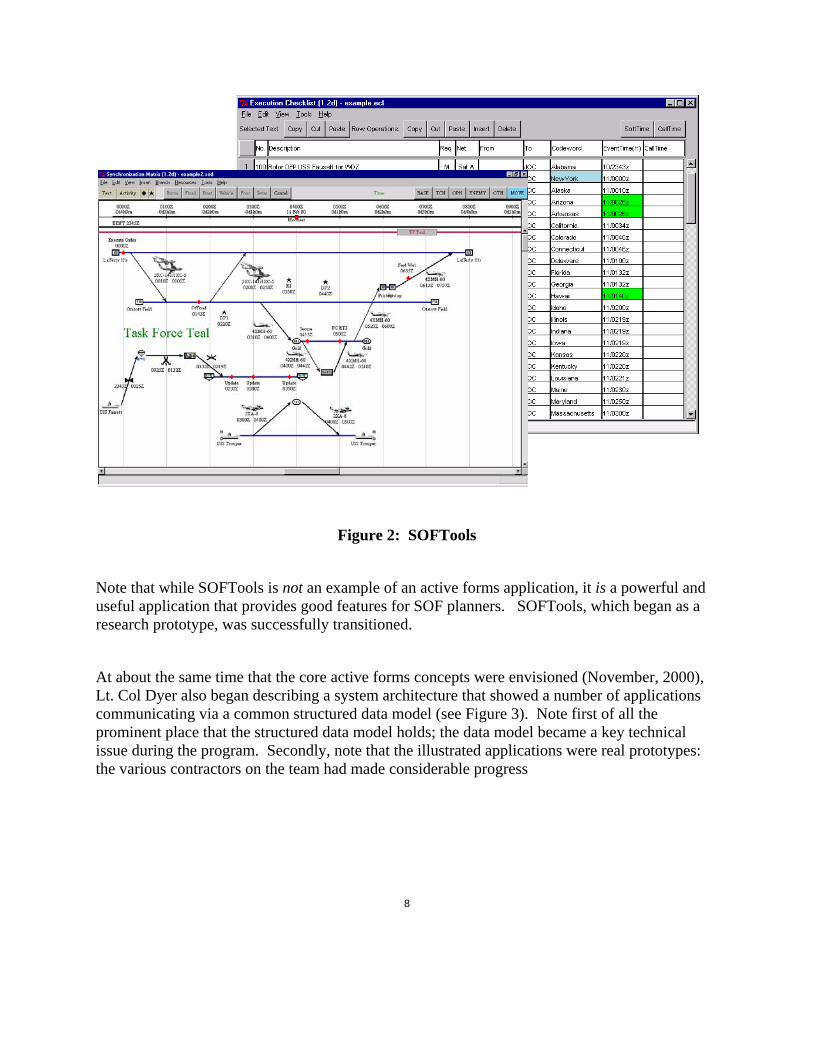
Figure 2: SOFTools
Note that while SOFTools is not an example of an active forms application, it is a powerful and useful application that provides good features for SOF planners. SOFTools, which began as a research prototype, was successfully transitioned.
At about the same time that the core active forms concepts were envisioned (November, 2000), Lt. Col Dyer also began describing a system architecture that showed a number of applications communicating via a common structured data model (see Figure 3). Note first of all the prominent place that the structured data model holds; the data model became a key technical issue during the program. Secondly, note that the illustrated applications were real prototypes: the various contractors on the team had made considerable progress

9
3.3 Active Templates Activities Like a number of other AcT contractors, SoftPro developed a number of prototypes, some gaining favor in the user community and some not. Several of these applications were like SOFTools in that they were useful tools but not true examples of the active form concept.
Figure 3: System Architecture
3.3.1 WeatherWrite WeatherWrite was an application developed for weather officers. During mission planning and execution, the weather staff is responsible for preparing a weather status briefing that summarizes conditions at the various locations “touched” by the mission. Preparing the weather briefing is a time-consuming and tedious task, perhaps taking a couple of hours each day. WeatherWrite was intended to simplify the process.
Terminal Aerodrome Forecasts (TAFs) provide the inputs for the briefing. A TAF is simply a weather forecast, expressed in a coded format that makes sense to meteorologists (and little sense

10
to everyone else). TAFs provide considerable information related to visibility, wind conditions, turbulence, icing, and so on. WeatherWrite parses the TAFs for each mission location and generates a graphic that is similar to the visual aid meteorologists would show the Commander. As shown in Figure 4, the graphic is a color-coded, time-based display that shows the predicted status (green-yellow-red) at each location. The constraints used for calculating weather status can be adapted to accommodate various kinds of aircraft and vehicles since weather is so important for ingress into and egress out of a mission location.
Figure 4: WeatherWrite Display
3.3.2 The Joint Operations Center (JOC) Log Command staffs need to maintain logs as events unfold during a mission. In the past, a command staff might use a tool such as MS Word or MS Excel for keeping a log. If the log needed to be shared in real-time, MS NetMeeting could be used as a collaboration environment. This kind of solution does not always work well – for example, MS NetMeeting is not always that reliable.

11
The JOC Log is a rudimentary active forms application designed to make it easier for command staffs to keep shared logs. Conceptually, the JOC Log is a very simple application. Users can specify the header and row-column layout to create logs such as the example in Figure 5.
Figure 5: The JOC Log
What makes the JOC Log an interesting application? First of all, the tool is designed to be much more reliable than MS Excel running over MS NetMeeting. SoftPro put considerable effort into issues such as connectivity so that users always know the status of their connection to the master form – certainly not a difficult technical issue but an important feature for real use.
More importantly, the JOC Log is interesting because of its collaboration model. The first releases of the tool provided “Wild, Wild West” collaboration – anyone could change anything on a log. Users initially thought this openness was desirable, but it became clear pretty quickly that boundaries needed to be established for collaboration. The collaboration protocol that evolved had considerable influence on later active forms use. In retrospect, the principles are fairly simple:
• The originator of a log session can see everything posted to the log.
• Participants in a session “own” the rows in which they enter data.
• Participants can change data in the rows they own, but they cannot alter data in rows owned by other people.
• Participants can “hide” rows from users if they choose.

12
The lesson learned is that collaboration has to be bounded and the controls applied to a form need to be very fine-grained. For a log, “fine-grained” control means that every row needs protection.
Though a simple application, the JOC Log was well-received by users, was deployed, and is being used in the SOF community.
3.3.3 CommandLink The JOC Log represents a partial step towards the notion of active forms. Logs are configurable and they are collaborative, but they are not really the new kind of “info-component” that Lt. Col Dyer envisioned. CommandLink, however, does provide users with the capabilities expected from an active form. SoftPro’s objectives for CommandLink are illustrated in Figure 6.
Figure 6: CommandLink Features

13
3.3.4 Decision Point Editor Decision making is one of the central activities in a command center. At least some SOF command staffs have formalized the process by representing decision making in terms of events, conditions, options and ramifications. An event, for which a decision is to be made, is dependent upon a series of conditions being satisfied. Options exist for conditions not met, and the selection of options has mission ramifications which must be understood.
To support this structured decision-making process, SoftPro developed a prototype Decision Point Editor, shown in Figure 7. The graphical representation shown in the top left of the figure is similar to MS PowerPoint graphics often developed by command staffs. Each node in the graph has supporting information like that shown in the form on the top right of the figure. This form is actually a collaborative active form which can be used either from the Decision Point Editor or from CommandLink. The bottom section in Figure 7 summarizes the status for each condition under consideration.
The Decision Point Editor was implemented as a prototype and was demonstrated to potential users. Although customers in the SOF community were considering its selection for refinement, hardening, and deployment, as of December 2004 this had not occurred.
Figure 7: Decision Point Editor

14
4. Technical Accomplishments Development of CommandLink is SoftPro’s primary technical accomplishment in the Active Templates Program. This section focuses solely on this application.
4.1 CommandLink Over a period of about 3 years, SoftPro developed increasingly capable prototypes of CommandLink. We concentrated first on implementing a basic human interface for form design, integrated with a client that allows users to view and enter data collaboratively. CommandLink’s collaboration model is distinctly different from document-centric paradigms. Assume that two users are viewing the same form. If one user changes a value on the form, that change is transmitted immediately to the other user: both users see the same data regardless of changes made to the form. Document check-in/check-out or manual form updates are not required; CommandLink synchronizes data views automatically.
During the course of the program, we addressed a number of other issues. For example, we
• Refined the component set available for form construction, with a surprising level of effort required to implement components such as date / time display, timer and countdown clocks. Components like these provide features tailored for mission planning and execution.
• Developed access control methods that work on an individual attribute basis – much more fine-grained that conventional document level protection.
• Implemented a form services capability. Form services provide a means to populate a form with either information from a data source, from web services (such as Fetch), and external programs.
All of this development was done using a scripting language known as Tcl/Tk. Originally developed as a scripting language for utility use, Tcl/Tk has evolved into a surprisingly capable language. It has a moderately broad user community and is powerful enough for developing fairly complex applications. Since it is an interpreted scripting language, Tcl/Tk is a good choice for rapid development and prototyping.
Unfortunately, Tcl/Tk has annoying shortcomings, particularly if the development goal is to build robust, deployable applications. Testing can be a chore – Tcl/Tk is interpreted, not compiled, and there is no way to discover coding errors except through repeated testing. Beyond a certain threshold for robustness, testing costs can outweigh the benefits provided through rapid development.

15
In addition, Tcl/Tk is not an object-oriented language, and structuring large programs can be a challenge. To address this problem, SoftPro developed a set of object-oriented extensions to Tcl/Tk.
Objects consist of two primary aspects: data and behavior. Tcl/Tk arrays were utilized to store the data for each instance of a class. Interestingly, arrays in Tcl/Tk can have arbitrary indices, and this was leveraged by using field names as indices. Each instance has its own array for data storage and it is named using the name of the instance pointer. In order to provide clean access to class behavior, a new function is generated for the instance that also has the same name as the instance pointer. When a “Tk-let” is defined, a smart function is automatically created that looks within the class namespace to automatically determine the set of methods that are available. This function is invoked through the instance pointer function to provide access to the appropriate methods by name.
As requirements for CommandLink evolved, we discovered other Tcl/Tk shortcomings, some of which severely limited CommandLink capabilities. For example, the language’s printing support is primitive, meaning that we were not able to implement useful form printing. Also, Tcl/Tk does not provide the functions needed for deploying applications through browsers. Users made it clear that a web-based version of active forms would be desirable.
CommandLink version 2.0, a fully tested and fully functional application, was released in June, 2004. This version was well received by users and was selected as a candidate for deployment. In late summer, SoftPro received additional funding, through a US Special Operations Command Advanced Concepts Technology Demonstration (ACTD) program, to prepare CommandLink for deployment. The first order of business was to re-implement CommandLink in Java, a language more suited for deployed systems.
The Java version of CommandLink has the key features of the Tcl/Tk version plus many additional capabilities. Three separate components have been developed:
• A Form Designer which has a more conventional look and feel, much like Adobe Photoshop or MS PowerPoint.
• A Form Client for using forms (i.e., viewing forms and editing form content).
• A Java Applet which allows users to view forms and edit form content through a browser interface.
In addition, the CommandLink Form Server originally delivered in June was enhanced to support the Java applet. In January 2005, the Java release, CommandLink version 3.0, was being tested and evaluated by the SOF community as a candidate for deployment.

16
4.1.1 CommandLink Feature Overview CommandLink is a tool for gathering, displaying, and sharing information. It's been designed to solve many of the problems we face when planning an activity or solving a problem collaboratively. All too often, the information we need is buried in databases or in written reports. Assuming that an application exists for getting what we need, we usually do not have any control over how information is organized and presented. In addition, we typically do not have any really useful methods for sharing information with other people working with us.
Put simply, CommandLink is a tool for getting the information you need, the way you need it.
Active forms are the basic building blocks in CommandLink. These forms are like the paper forms we use all the time -- though they are much more powerful and, hopefully, a lot less annoying to use. Active forms are "active" because they can be:
• Created and customized by users
• Stored as templates and reused as needed
• Linked to data sources for populating fields
• Shared with other people, with controls over who sees what data
• Connected with databases, web services, and custom services that may interact with intelligent software agents that perform calculations, make recommendations, recognize patterns and so on.
CommandLink has 2 major components: the Designer to create forms; and the Client to interact with the data on forms.
4.1.2 CommandLink Form Designer CommandLink Form Designer is a tool for enabling users (not programmers) to create, share, modify, and reuse forms. It also provides some controls so that shared forms cannot be arbitrarily changed without their authors' consent.
We distinguish between a form's structure and its content. The structure of a form is defined by the set of display elements it contains (its components) and how these display elements are organized on the form. The content of a form is defined by the data values for each of these display elements. The Designer manages form structure. It also provides for access control to

17
the data values through access permissions. These access permissions can provide for read-only access to data and to hide a component completely from selected users.
There are 4 sections in the Designer window as illustrated in Figure 8. In the upper left of the figure is a navigation pane displaying the components on a form in hierarchical manner. You may select a component to edit by clicking on it in this pane. Below it is the Properties pane which lists all the changeable properties of the selected component or form. In the upper right is a toolbar displaying selectors and available components. The main display below the toolbar is the form canvas for creating and editing the form.
Figure 8: CommandLink Form Designer
4.1.3 CommandLink Form Components Forms are composed of individual components and containers which are used for holding and organizing these elements. The simple form shown below illustrates the distinction between

18
components and containers. Components of similar data type can be linked directly or as part of a mathematical calculation. This linkage can simply make the same data available in multiple forms, or abstract the data to a different representation. A common example of abstraction is linking a numeric data element to a status component with color ranges set on the data value – a useful feature for creating dashboards.
Figure 9: Form Components and Containers
4.1.3.1 Form Components Form components are the individual data elements that are assembled into a form. The current library of components is described below, but new components are easily developed using the component class structures in the Active Forms library.
Alphanumeric:
• Label - a multi-line alphanumeric text data item useful for headings, instructions, etc. • Entry - a single-line alphanumeric data item with an optional data entry mask.

19
• Text - a multi-line alphanumeric data item
Numeric:
• Numeric - a numeric data item • Scale - a sliding scale over a user-specified range
Date / Time:
• Date - a user-formatted date field that provides a calendar for entry with selectable military or civilian time zones.
• Clock - a user-formatted clock display selectable military or civilian time zones. • Timer - an elapsed time counter. • Countdown Clock - A clock that counts down to a future, user-specified date/time.
Selectors:
• CheckBox - a labeled check box • RadioButtons - a set of radio buttons with user-defined choices allowing only one active
selection • ComboBox - a drop-down list of user-defined selectable items
Miscellaneous Components:
• Hyperlink - a descriptive link to a URL • Image - a scaleable image • Status Indicator - a multi-colored indicator that may be connected to a value to change
color automatically Tables and Logs:
• Table- a multi-column array of cells of several component types • Table Log - a table with special properties for control of row ownership and behavior
4.1.3.2 Containers Containers are aggregators of form components. The form itself is a top-level container. In addition to providing means to organize components, containers are also savable as templates making them reusable for creation of new forms or form elements.
• Frame: a general purpose container that can be inserted anywhere on a form. A frame is most useful to collect similar data elements, such as an address.

20
• Notebook: a container which has one or more pages, each of which is a container itself. In the example shown above in Figure 9, the notebook has four pages where three pages may be similar in structure and the fourth completely different.
4.1.4 Forms and Templates CommandLink distinguishes between forms and form templates. Forms are exactly what one would expect: they are like paper forms. Users can enter data in CommandLink forms, share forms, link data on one form to another form, and so on.
Form templates are reusable patterns that can be used for designing new forms. Once a template has been created from an existing form or a container on a form, it can be used again to create forms or add repeated sections of data to a form. For example, we might create an Address template that could be used repeatedly in forms that require a person or company data. Templates can be stored either locally (on the user's machine) or on a server and are editable in the Designer.
4.1.5 Workspaces and Workgroups In CommandLink, active forms provide a way to gather, display and share information. CommandLink's user interface consists of a set of tools for creating, storing, organizing, and sharing forms.
Forms can be stored in either workspaces or workgroups:
• A workspace is a container for storing forms on a user's own machine. A workspace is like a top-level directory. Workspaces contain folders and forms. Forms in workspaces are private; no one else can see the data on these forms.
• A workgroup is a container for storing forms on a shared CommandLink server. Forms in workgroups are public; subject to access permissions, other people can see and change the information on these forms.
4.2 Form Client The Form Client is an application to allow users to interact with the data on a form. The From Client may be accessed as either the standalone application installed in the CommandLink suite, or as a browser applet from a server using programs such as Internet Explorer or Netscape.

21
The Client control pane, Figure 10, displays local workspaces and the workgroups available on the form server to which you have connected. From this display, a selected workgroup or workspace will open a Form Explorer display as illustrated in Figure 11.
Figure 10: CommandLink Client Control Pane
Figure 11: Client Form Explorer

22
This Explorer window displays the open workspace or workgroup, its folders and forms, and a form display pane to right. When a form is selected in the Explorer pane, it is opened in the form display area as a tabbed window. Data and controls on the form are fully accessible to the user. The Explorer pane also provides for folder and form management – adding, deleting, or renaming folders and forms.
4.3 Services Services provide a means for accessing external data so that it can be displayed on forms. CommandLink provides two basic services and its capabilities can be extended using custom services. Custom services are created by programmers to provide access to other software such as intelligent software agents that perform calculations, make recommendations, or recognize patterns.
The two basic CommandLink services include web services, such as Fetch Agent Platform agents, and access to Open Data Base Connectivity (ODBC) data sources. The user is provided wizards to rapidly create services that access ODBC data sources to provide discrete fields of data or tables of records from queries to the data source. The ODBC data sources include many databases, such as MySQL® and Microsoft Structured Query Language (SQL) Server, and applications such as Microsoft Excel.
4.4 Form Sets Form Sets provide a Client user a simple means of saving and reusing a collection of related forms for another task.. For example, a specific folder for a mission may have a set of forms: a Commander's Dashboard, a Logistics form for each unit, or a set of interconnect status forms. Unlike authoring forms in the Designer, this feature provides Client users a ‘run-time’ capability to add forms to their workspace or workgroup.
4.5 Important CommandLink Concepts Summary
1. Form
A CommandLink form is like a paper form, except that CommandLink forms enable people to capture and share data electronically.

23
2. Collaboration
Collaboration provides a means for sharing the information on a form among multiple users. Forms stored in workgroups are collaborative.
3. Component / Widget
A component or widget is a display element on a form. Components typically have a label and a field for entering a value.
4. Container
Containers are used for grouping and holding widgets. Containers are important because they provide a means for laying out forms in attractive and useful ways.
5. Template
A template is a re-usable building block for creating forms. Templates look just like forms -- except that they are intended to be incorporated over and over again in forms. Like forms, templates are composed of components that are organized within containers.
6. Workspace / Workgroup
Workspaces and workgroups provide a means for storing and organizing forms. Workspaces are private storage areas; workgroups are public storage areas.
7. Data linking
Information on one form can be linked to another form, meaning that any changes to the first form will be reflected by changes to the second form. Data linking is an important feature for collaboration.
8. Form Sets
Collections of related forms can be saved as a Form Set so that any user can easily create a copy of those forms for a new purpose. For example, a set of personnel forms can be saved as a set and created for each employee.

24
9. Services
Services provide a means for populating forms with data from external sources such as a database, an agent that extracts data from a web page, or a program that performs calculations. The most common examples are database services.
10. Permissions -- Access and Authoring
Access permissions provide a means for controlling who can view or modify the fields on a form. Authoring permissions provide a means for controlling who can change the appearance of a form.

25
5. Lessons Learned
5.1 Programming Languages and Methodologies We noted above that much of the code SoftPro developed for this effort was written in Tcl/Tk. (In fact, the DARPA program office strongly encouraged the use of Tcl/Tk.) For the most part, Tcl/Tk was a good choice as long as we were prototyping. As CommandLink’s requirements grew, Tcl/Tk’s limitations became more apparent. The language was particularly restrictive in control of component layout on a form leading to a problem discussed below. The language is an interpreted language with some performance limitations that restricted form complexity and often resulted in slow performance for large forms.
The key development model for CommandLink was rapid prototyping and requirements discovery through frequent delivery cycles to our user representatives from the SOF community. Frequent prototype delivery facilitated valuable interactions to identify requirements. However, the development team’s desire to be responsive to requested changes without proper software development controls and policy introduced levels of complexity and resulted in sometimes brittle software.
The transition to Java introduced new complexities and issues. Most significant was the desire for backward compatibility with existing forms. While at the surface this was a reasonable objective, it resulted in significantly inefficient use of development time and program resources. The Tcl/Tk version 2.0 software was, by necessity of the language, not explicit in component positioning within a form. Form rendering of components was based on order of expression within the XML, within any container constraints such as column definitions – that is, component position was relative. Therefore, the initial Java Client, which was developed as an applet to provide a browser access to forms, was required to replicate the relative rendering of components to mimic the Tcl/Tk software. This in itself was not necessarily a problem. However, this notion of backward compatibility carried into the next phase of development highlighted by a new authoring tool, the Designer.
The Designer did not maintain the paradigm of relative, and relatively uncontrollable, positioning of components on a form. Rather it correctly maintained an explicit form location for each component to allow authors precise control of form layout, appearance, and rendering. At this point, the programming effort to save a few hours of recreation of forms created in the prior ‘relative’ version of CommandLink by providing compatibility with the Designer resulted in significant engineering hours towards that end that could have been better assigned. It also was then readily apparent that the time spent building the initial Client applet to faithfully render

26
the older forms was also somewhat wasteful. The fundamental software elements of the applet for rendering components, providing active links and services were useful and reusable. Engineering hours spent recreating faithful relative form rendering were indeed wasteful. The absolute positioning expressed in the new Designer made that initial effort no longer useful except for backward compatibility. The value of backward compatibility however, is questionable given that the existing older forms were examples and tests, not production or fielded forms. A few hours of effort to recreate an old form in the new Designer was traded for hundreds of engineering hours providing backward compatibility.
Testing of the Java version raised significant new issues. As discussed above, our software development methodology, developed and nurtured during the initial DARPA-funded portion of this effort, called for frequent interaction with our user representatives as test and evaluation resources, in addition to their role in requirements discovery. The process was to provide a release candidate (a beta version in software release terminology), identify issues, and iterate on the process until a final full product release. When the version 2.0 software was delivered for testing in June 2004, user representatives were able to perform functional and operational testing as had been the norm to date in the Active Templates program, working in an iterative fashion with the developers who provided frequent releases with bug fixes. SoftPro understood the same method of test and evaluation would be used with the first Java version 3.0 release candidate delivered in December 2004 and developed under US Special Operations Command funding. After a round of intermittent and problem-plagued iterations in January 2005, end-user resources were no longer available for iterative testing and evaluation. SoftPro was still expected to deliver a fully tested deliverable at the end of the contract. SoftPro mounted an extensive internal and contracted testing effort resulting in a final product release in March 2005. As of this report the software was still undergoing acceptance testing by the SOF community.
Lessons Learned
1. Scripting languages such as Tcl/Tk are very good for rapid prototyping and development but limited in value for product deployment and support.
2. Tcl/Tk’s benefits erode as an application matures. We struggled with
a. The language’s lack of structure (Tcl/Tk is not object oriented)
b. Performance problems
c. Lack of features such as printing and browser support.
3. Develop, coordinate, and maintain an agreed-upon and prioritized set of requirements scheduled in managed prototype cycles.
4. A cost/benefit analysis of backward compatibility is a valuable exercise towards useful application of engineering effort versus recreation of prior forms.

27
5. Test planning and resource assignment must be well-understood, costed and scheduled at the beginning of a development effort.
6. As a product development activity, rather than a research activity, requirements and acceptance criteria must be established at the beginning of the development cycle.
5.2 Usability This effort, like many DARPA research projects, placed little interest in the niceties of the user interface and mechanization that is critical to usability and user acceptance. In fairness, user interface research was not a stated goal of the Active Templates Program. As the research project evolved into a product development project issues of user interface design and mechanization became a critical goal on the part of the user representatives, and thus a major focus of development activity. This created a constant dynamic conflict between the core research objectives of DARPA and the desire for a useable software tool by the end-user community. The problem was exacerbated by limitations in user interface support imposed by the selection of Tcl/Tk as the initial development language. When the Java re-engineering effort occurred at the end of the research phase, one key focus was creating an intuitive, capable and useable user interface for form design.
Lessons Learned
1. Inattention to proper human-engineered user interface design practices can prove wasteful of engineering resources while compromising user acceptance.
2. The overall success or failure of a project may be independent of the success or failure of the underlying research and instead be dependent on user acceptance of the product solution.
5.3 Collaboration
We distinguish between document-centric collaboration models and attribute-centric models. Document oriented collaboration allows users to work collaboratively on documents. Microsoft Word and Microsoft Sharepoint are good examples of document oriented models. The document in itself is the basis for collaboration -- people share the entire document; access protections exist at the document level; and documents themselves are checked-in and checked-out.
Users in the mission-planning community made it clear that document-centric collaboration is insufficient. Users need to be able to share individual bits-and-pieces of information, and they do not want to have to check-in and check-out documents to propagate changes.

28
Lessons Learned
1. Fine-grained collaboration models are more useful in mission planning/execution than coarse-grained models.
5.4 Structured Data Model Figure 3, Active Templates System Architecture, presented in Section 3.2 of this report, illustrates the architecture for a set of mission planning tools integrated via a structured data model. Active Templates team members spent a considerable amount of time working together to develop a satisfactory data model. We encountered a number of practical problems, most of which were related to a lack of understanding about the contents of the “right” data model. We struggled over questions such as
1. How comprehensive should the model be?
2. Should the model be designed in a way consistent with existing databases or should it be designed to support new AcT technologies that require new data representations?
3. Should the model be tailored for performance or extensibility?
4. Who can provide the domain expertise for creating a model useful in the real world?
None of these questions is trivial – in fact, the questions are difficult enough that AcT structured model development failed. To be fair, the effort might have succeeded under other circumstances. Model development activities were loosely coordinated, and no one on the team was empowered to make and enforce decisions. Perhaps a more autocratic approach would have yielded a model, though most likely no one would have really liked the end result.
Lessons learned
1. Structured data model development is difficult and time-consuming. Very strong leadership is needed for the process to succeed.
5.5 External Services and Programs As described in the AcT BAA solicitation, a key program objective was to integrate “symbolic problem solvers and external data sources with simple but expansive visual interfaces”. CommandLink provides a form services capability intended to address this need.
Form services are a good idea that was not fully exploited during the program. On the positive side, CommandLink can access any ODBC-compliant database. In addition, CommandLink has been integrated with the Fetch Agent Platform, a web-scraping application.

29
The Fetch Agent Platform integration uncovered some important issues. For example, assume that a Fetch Agent Platform agent has been created for gathering weather data at any place in the world. The input to this agent might be a location. How should this location be specified? As a latitude/longitude? As a UTM? There needs to be a way to specify both the input requirements and output specification for every external agent connected to CommandLink. At the time when SoftPro integrated with the Fetch Agent Platform, this infrastructure did not exist and hence using the Fetch Agent Platform was an awkward process.
Imagine how the situation might have been different if CommandLink were deployed within a rich web services framework. Most of the issues associated with external agent integration would be handled by protocols that are just now beginning to be used.
We can even imagine very different roles for power users and developers. If developers were to concentrate on deploying data sources and problem solvers within a web services framework, then power users could concentrate on building active forms to solve real-world problems.
Lessons Learned
1. The broad goal of integrating active forms with external problem solvers and data sources can be realized when web services are more widely available.

30
Appendix A: Comparative Product Analysis The following comparative analysis includes examples and discussion relevant to CommandLink (Active Forms) version 2.0 as implemented in Tcl/Tk. In particular, discussion related to author and user modes is obsolete with respect to the Java version 3.0 interface.
Introduction
Why so much interest recently in electronic forms? During the past two years, major players in the software industry such as Adobe and Microsoft have released main-stream products for creating and using forms. While Adobe and Microsoft were implementing their products, DARPA was funding the Active Templates program, an effort focused on enabling users to create intelligent, forms-based interfaces. By mid-2004, both Adobe’s Form Designer and Microsoft’s InfoPath were being sold commercially, and CommandLink, an active forms application for the military, was being readied for deployment to Special Operations command centers. Yet electronic forms have been around for years.
More is going on here than one might think. Adobe’s Form Designer and Microsoft’s InfoPath are essentially evolutionary products. They extend familiar ways of thinking about computing. Over the years, users have become accustomed to creating and sharing documents using tools like MS Word and MS PowerPoint. Form Designer and InfoPath provide the means to manipulate a different kind of document – electronic forms. Granted, Form Designer and InfoPath have some very powerful new features, but for the most part these are evolutionary tools.
In contrast, DARPA’s intention for the Active Templates program was considerably more ambitious. The early tag line for the program was “spreadsheets for planning”. Both terms in the tag line are important – “planning” because the intention was to provide users with powerful tools for solving hard military planning problems and “spreadsheets” because the capability should be provided in a framework which users can configure however they need. The program objective for Active Templates was to bring powerful knowledge-based planning tools under user control. As such, Active Templates is the successor to DARPA research that started with the Strategic Computing Initiative in 1983 and continued through the ARPA Rome Planning Initiative (ARPI) which spanned the 1990’s (Figure A-1).
The Strategic Computing Initiative Program focused considerable attention on a set of core technologies such as hardware systems, vision, speech understanding, and expert systems.

31
Application development programs such as the Pilot’s Associate provided a venue for applying these technologies to hard problems. Roland and Shiman [1] argue that R&D activities in hardware systems and speech understanding were successful, while vision and expert systems development were disappointing.
Figure A-1: Active Templates Historical Context
The knowledge-based systems R&D funded by DARPA during the past 20 years range from early development of expert system shells, through development of associate systems, and implementation of intelligent planning and scheduling tools. Much of this work was a precursor to current thinking about intelligent agents.
The DARPA Active Templates (AcT) program has served as a test bed for many of the ideas associated with agent-based intelligent forms (ABIF). The AcT program had two areas of emphasis: to develop the basic concepts and prototype software for realizing the vision for intelligent forms; and to deploy at least a few working forms applications to military users, specifically command staff planners in the Special Operations community.
What is an “agent”? The Massachusetts Institute of Technology (MIT) Media Laboratory defines an agent as “software that acts as an assistant to the user rather than a tool, learning from interaction and proactively anticipating the user’s needs” [2]. Carnegie Mellon researchers have a slightly different take: “an agent is an autonomous, (preferably) intelligent, collaborative, adaptive computational entity. Here, intelligence is the ability to infer and execute needed actions, and seek and incorporate relevant information, given certain goals” [3].
Regardless, agents are different from tools. Though not described as an agent-based application, the DARPA Pilot Associate (PA) program is a source for many of the ideas associated with agents. The PA was a collection of cooperating expert systems designed to aid pilots in air-to-air combat. It was designed to monitor the combat situation, suggest plans for countering threats; and, when given the right permissions, to act on the pilot’s behalf. Though the PA was not

32
deployed, the principles resulting from this R&D represent what the AI community was thinking 15 years ago about human-computer interaction. Today’s vision for agent-based intelligent forms has a lot in common with associate systems.
Commercial Form Tools Although they are useful, feature-rich, and practical, the form-based applications available today fall short of the ABIF vision. Both Adobe Form Designer and Microsoft’s InfoPath exemplify conventional ways of thinking about software: these products are tools, not agents.
Business Problems Addressed Form Designer is a component of Adobe’s strategy to provide “intelligent document” solutions. Adobe describes Form Designer as a product which:
…enables companies to replace inefficient, paper-based forms processes with intelligent, accessible and secure electronic data capture solutions to improve organizational agility and productivity. [4]
From Adobe’s perspective, organizations suffer because they have large paper backlogs. The route out of this morass is to enable business processes with intelligent documents for gathering and managing information and to integrate information with an organization’s existing systems
Microsoft’s intentions are a bit different. Though recognizing that InfoPath provides an effective way to gather business data, Microsoft has a broader intent:
Key decision makers are often unable to make informed decisions because the information they need is trapped within documents or databases in another part of the organization. Technologies such as the Extensible Markup Language (XML) and Web services have been helpful in improving business processes from server to server, but to date they have not been connected directly to information workers at their desktops. This has meant that information workers have not had a way to interact with Web services directly to access and use the enterprise information that they need. [5]
Rather than just being a means for gathering information from people, InfoPath is intended to be a means for integrating an organization’s various back-end systems via forms-based interfaces. End users benefit because they get the information they need; IT departments benefit because development and deployment are easy.
33
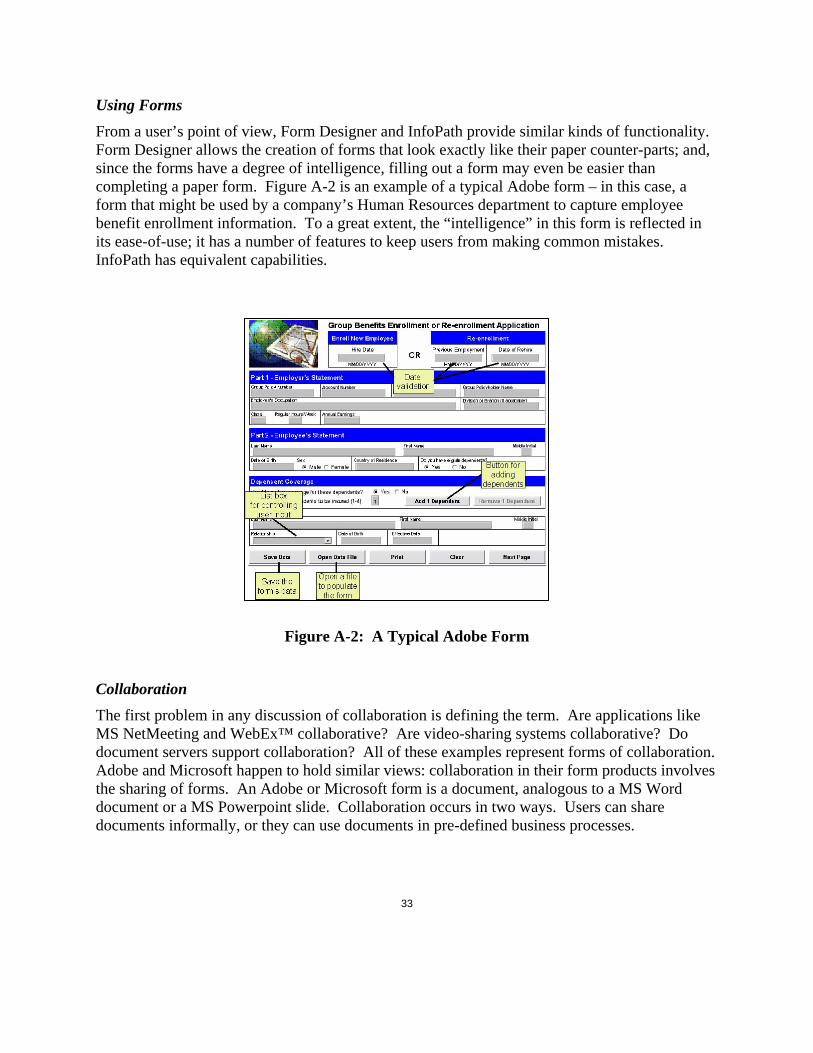
Using Forms From a user’s point of view, Form Designer and InfoPath provide similar kinds of functionality. Form Designer allows the creation of forms that look exactly like their paper counter-parts; and, since the forms have a degree of intelligence, filling out a form may even be easier than completing a paper form. Figure A-2 is an example of a typical Adobe form – in this case, a form that might be used by a company’s Human Resources department to capture employee benefit enrollment information. To a great extent, the “intelligence” in this form is reflected in its ease-of-use; it has a number of features to keep users from making common mistakes. InfoPath has equivalent capabilities.
Figure A-2: A Typical Adobe Form
Collaboration The first problem in any discussion of collaboration is defining the term. Are applications like MS NetMeeting and WebEx™ collaborative? Are video-sharing systems collaborative? Do document servers support collaboration? All of these examples represent forms of collaboration. Adobe and Microsoft happen to hold similar views: collaboration in their form products involves the sharing of forms. An Adobe or Microsoft form is a document, analogous to a MS Word document or a MS Powerpoint slide. Collaboration occurs in two ways. Users can share documents informally, or they can use documents in pre-defined business processes.

34
For example, using Form Designer, people can collaborate by E-mailing forms to one another or by working within a process that is managed by the Workflow Server. InfoPath users can export form data to MS Excel or mail forms to other users with MS Outlook. If an organization runs MS SharePoint, users can store forms on a common server to facilitate collaborative editing or viewing of the form. Forms can also be integrated with business processes using Microsoft’s BizTalk server.
When defined in these ways, collaboration is a fairly static process. Neither Adobe Forms nor Microsoft InfoPath can learn a workflow – process steps need to be defined in advance. Note that this collaboration model is coarse-grained: documents are the currency exchanged between users.
Designing Forms Anyone should be able to use an Adobe or Microsoft form; however, not all users will be able to design forms. The Adobe Form Designer looks and feels like a software Integrated Development Environment (IDE). Figure A-3 illustrates the Adobe Form Designer interface. The left-hand side is a canvas for form design. Form elements, such as text boxes or radio buttons, are dragged-and-dropped onto the canvas and positioned wherever they need to be. The designer is flexible enough to allow the recreation of essentially any paper form.
Figure A-3: Adobe Form Designer Interface

35
Designing a form with InfoPath is considerably different from doing so with Adobe Form Designer. InfoPath is advertised as a tool for editing XML documents; accordingly when a designer creating an InfoPath form is actually creating an interface for viewing an XML file. Figure A-4 illustrates InfoPath’s design mode. The left-hand portion of the display is a design space; layout containers (such as multi-column tables) and controls (e.g., text boxes, date displays, drop-down boxes) can be dragged-and-dropped onto the form canvas. Working with Adobe Form Designer is analogous to working with a drawing program; working with InfoPath is like working with a Word document. While flexible, InfoPath does not provide the same kind of pixel-by-pixel layout control offered by Adobe’s product.
Designers can begin creating a form one of two ways: by designing a New Blank Form or by designing a New Form from a Data Source. Why the distinction? InfoPath forms are represented using XML; and, consistent with conventional practice, Microsoft makes a clear distinction between the XML specification for a form’s data source and the XML for its presentation. Every control on an InfoPath form is bound explicitly to an element in the form’s data source, and form designers need to be mindful not only of how a form appears but also how form controls map to the form’s data structure.
Figure A-4: InfoPath Design Mode
Designing a new blank form is the simpler case, one that does not require much awareness of the form’s data schema. As the designer adds and edits controls, InfoPath updates the form’s underlying schema. In this case, the user need not be concerned about the data schema.

36
Designing a new form from a data source is a more involved. InfoPath supports three kinds of data sources: XML schemas, ODBC data sources (SQL Server and Access only) and Web services. Figure A-5 illustrates form design using an ODBC data source.
Figure A-5: Form Design from an ODBC Source
In this example, the form designer’s first task was to find an ODBC data base to serve as a data provider; InfoPath provides a wizard for locating a data base and selecting tables. (All of the tables shown on a form have to be from the same data source; mixing and matching data sources is not supported.) Once a data source is specified, InfoPath creates the data source specification for the form and two form views, one for querying the data source and one for entering data. Because the form is tied to the data source schema, and the data source mirrors the database structure, flexibility is limited. Suppose, for example, that a designer wanted to add a new field to the form to capture the name of the person who enters new item information. Adding a new control is possible – but the form’s data source has to be modified first with a new field so a mapping can be made between the control and the data source. Unfortunately, since the new field is not stored in the database, there is no way to retrieve what is entered.
Implementing Complex Behaviors
Both Form Designer and InfoPath enable users to design functional forms without an inordinate amount of training or a degree in computer science. However, there are limits to what users can implement without at least a basic knowledge of programming.

37
Behind its display interface, an Adobe form is a collection of objects with properties, methods, and events. The Property Browser provides an easy way to set the attributes of an object such as its background color, size, position, and font. Methods are actions that change the state of an object. Events are responses to an external action, such as a mouse click. Both methods and events are implemented through scripting using either VBScript, Jscript, or a default scripting language provided by Adobe. In any case, designing forms with complex functions is beyond the capabilities of ordinary users.
Building forms which exhibit complex behaviors is equally challenging in InfoPath and requires programming using either Jscript or VBScript. Form behavior can be customized by writing code for data validation, for error handling, for handling specialized data submission and merging requirements, and for accessing external data sources. InfoPath provides a COM-based object model for interacting with forms and the XML documents that are used for representing these forms. Programming with this model would clearly be beyond the capabilities of ordinary users.
AI Influence On Commercial Products Adobe Forms and InfoPath are feature-rich products. But do they have any capabilities at all which suggest influence from AI research? Regrettably, the answer is no. These are interesting, useful, powerful, and commercially viable applications, but they do not exhibit any real intelligence. Ten years ago, people collaborated by sharing MS Word, MS PowerPoint and MS Excel documents. Today’s forms-based applications enable users to collaborate by exchanging forms, they make it easier to gather information from data sources and to leverage forms in work processes. Adobe Forms and InfoPath are very good tools.
However, these are not intelligent forms. Other than being able to perform error checking or other low-level tasks, the forms have no understanding of the tasks being performed, how the user can be aided effectively, or how forms should be adapted to suit the situation at hand.
SoftPro Active Forms
Business Problems Addressed
By the late 1990’s considerable additional research had been done at DARPA related to planning and scheduling. However, with a couple of exceptions, military officers still used manual

38
processes – and tools like Microsoft Office -- for building plans and monitoring their execution. Figure A-6, from a DARPA program review in 2000, summarizes the problem [6].
Figure A-6: Military Planning is Predominantly Manual
One of the key issues identified in this viewgraph is the need for structure. Products like MS PowerPoint and MS Outlook lock data in an unstructured format that prevents the sharing of data between applications. Most importantly, as long as users rely on tools like Office, they will not be able to fully exploit the intelligent planning, scheduling, and decision making technologies that were developed through Strategic Computing and ARPI. For example, if a change in mission start time (H-hour) is communicated in an E-mail, it cannot be automatically propagated to automated scheduling tools. For all intents and purposes, the information is useless with respect to easy integration with automated systems.
By observing what military planners do, Active Templates researchers were able to derive a number of high-level requirements.
• First, forms have to be very flexible, just like Microsoft Office products. Since SOF missions are guaranteed to evolve over time, users must be able to create and modify forms to suit their particular needs.
• Because mission management is a collaborative and time-sensitive process, forms must be collaborative. Users must be able to share and track changes to data in real-time to a very fine granularity -- at the level of individual attribute values, not simply documents at the document level.
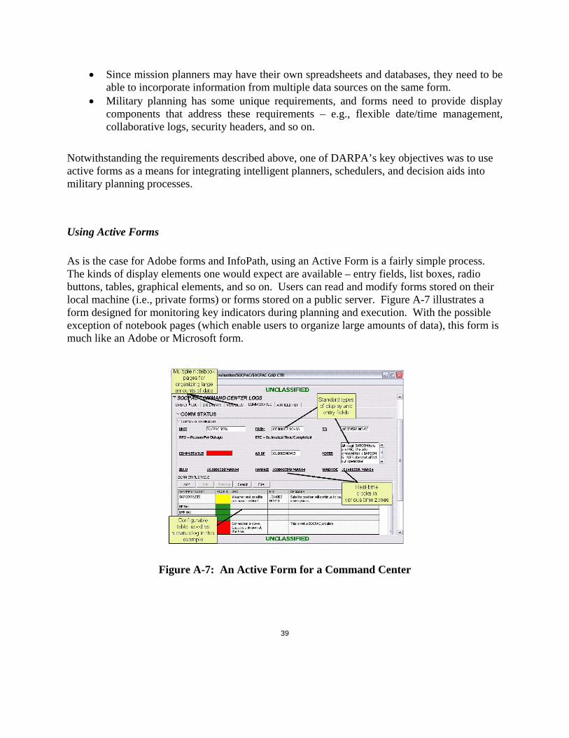
39
• Since mission planners may have their own spreadsheets and databases, they need to be able to incorporate information from multiple data sources on the same form.
• Military planning has some unique requirements, and forms need to provide display components that address these requirements – e.g., flexible date/time management, collaborative logs, security headers, and so on.
Notwithstanding the requirements described above, one of DARPA’s key objectives was to use active forms as a means for integrating intelligent planners, schedulers, and decision aids into military planning processes.
Using Active Forms As is the case for Adobe forms and InfoPath, using an Active Form is a fairly simple process. The kinds of display elements one would expect are available – entry fields, list boxes, radio buttons, tables, graphical elements, and so on. Users can read and modify forms stored on their local machine (i.e., private forms) or forms stored on a public server. Figure A-7 illustrates a form designed for monitoring key indicators during planning and execution. With the possible exception of notebook pages (which enable users to organize large amounts of data), this form is much like an Adobe or Microsoft form.
Figure A-7: An Active Form for a Command Center

40
Collaboration However, Active Forms have a number of unique features that reflect the particular domain problems they were designed to solve. Remember that mission planning and execution tracking is a real-time, collaborative process. When an Active Form is saved to the public server, it becomes a shared item that, subject to access permissions, can be viewed and edited simultaneously by multiple people. For example, if a Colonel is viewing a form which displays information for Forward Staging Base Bravo, and a Major updates the data on that form or a related form, the Colonel will see these changes immediately, without having to refresh or check-out the form again. Access permissions available on every form field provide fine-grained control for viewing and changing data.
Designing Forms Active Forms have two modes: an author mode for designing forms and a user mode for filling out and interacting with forms. (Active forms can also be deployed to the web.) An Active Forms author builds a form by arranging display elements on a grid. Containers (e.g., frames and notebook pages) provide organizing flexibility and can be configured to have any number of columns. Figure A-8 illustrates a form in authoring mode.
Figure A-8: Active Forms Authoring Mode Authors add components by clicking on an editing icon and then making selections from a wizard. By default, new components are inserted at the bottom of a container, but they can be dragged-and-dropped anywhere. Active Forms provides a library for storing reusable sets of components or entire forms as templates. While it is possible to create many different kinds of
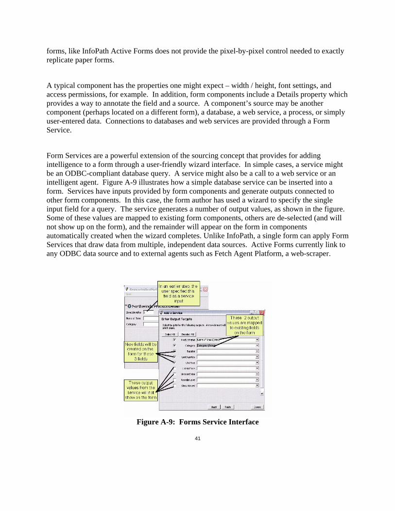
41
forms, like InfoPath Active Forms does not provide the pixel-by-pixel control needed to exactly replicate paper forms.
A typical component has the properties one might expect – width / height, font settings, and access permissions, for example. In addition, form components include a Details property which provides a way to annotate the field and a source. A component’s source may be another component (perhaps located on a different form), a database, a web service, a process, or simply user-entered data. Connections to databases and web services are provided through a Form Service.
Form Services are a powerful extension of the sourcing concept that provides for adding intelligence to a form through a user-friendly wizard interface. In simple cases, a service might be an ODBC-compliant database query. A service might also be a call to a web service or an intelligent agent. Figure A-9 illustrates how a simple database service can be inserted into a form. Services have inputs provided by form components and generate outputs connected to other form components. In this case, the form author has used a wizard to specify the single input field for a query. The service generates a number of output values, as shown in the figure. Some of these values are mapped to existing form components, others are de-selected (and will not show up on the form), and the remainder will appear on the form in components automatically created when the wizard completes. Unlike InfoPath, a single form can apply Form Services that draw data from multiple, independent data sources. Active Forms currently link to any ODBC data source and to external agents such as Fetch Agent Platform, a web-scraper.
Figure A-9: Forms Service Interface

42
Implementing Complex Behaviors Active Forms, Adobe forms, and InfoPath share similar constraints with respect to implementation of complex behaviors: there is a limit to what ordinary users can do. Complex functions often require programming. In Active Forms, three kinds of implementation of complex behaviors are possible: new display components may be created building on the core component architecture; connections to external processes can be made through Form Services or action buttons; or creating an application wrapper that manages form interactions.
Conclusions When measured against the benchmark established for an agent-based intelligent form, active forms suffer from some of the same shortcomings as Adobe Forms and InfoPath. For example, active forms are neither ‘active’ or ‘intelligent’ in the way we would like them to be. Remember that we have defined an agent as an “assistant to the user rather than a tool, learning from interaction and proactively anticipating the user’s needs.” Though they have a number of very useful capabilities, active forms are still more like tools than user assistants. In addition, active forms cannot yet learn from the user.
However, there are reasons for thinking that active forms are a key step in the right direction. Though the difference may not be obvious to people who are authoring or using simple forms, active forms do have some features that make them significantly different from different from other commercial products. Most importantly, while Adobe Forms and InfoPath treat forms as documents, active forms are collections of attribute-value pairs that are displayed as forms.
This apparently minor difference has some significant implications related to current capabilities and future utility. For example, the currency exchanged during collaboration is fine-grained in an active form – changes to a single attribute are immediately available to other people. Data linking is supported at an attribute level. Read / write permissions are controlled by attribute. Access to external components (e.g., Fetch Agent Platform agents) is managed at the attribute level.
The distinction between forms-as-documents vs. forms-as-Attribute-Value-Pair (AVP)-sets provides the foundation for capabilities needed in ABIF’s. We can think of active forms as a framework for gathering information, as an environment for controlling the invocation of external agents, and as a mechanism for displaying results. Active forms can already do these kinds of things.

43
What is lacking is an infrastructure that can be exploited for making forms more intelligent. Databases, software interfaces, and communication protocols were designed for programmers, not users. This is perfectly reasonable since programmers have historically been responsible for application building. InfoPath exemplifies this way of thinking: how many users really care about editing XML documents?
We can think of this problem as a packaging issue in part. We clearly need libraries of intelligent agents as a starting point. Not many of these agents exist yet. In addition, once agent libraries are available, form developers will need to know about the components in the libraries and how they can be used effectively. Put in simple terms, rather than providing users with a view of a database’s tables, we might expose a set of business objects that represent the database’s contents. For external components (e.g., a scheduling algorithm), we need to provide users with meta-data which describes the component’s inputs, outputs, functional capabilities, limitations, and so on. These are not new ideas – the web community has been working for some time on languages such as Resource Description Framework (RDF) and Ontology Web Language (OWL) for supporting agent-to-agent communication. The same techniques could be used for describing external components to users.
A second problem is cultural. To really encourage the adoption of ABIF’s, we need to rethink what users do and what programmers do. In most organizations, users describe what they want an application to do and they wait for the information technology staff to deliver a product. We clearly cannot train all the users to be developers, but we can make it easier for users to assemble intelligent forms. Rather than building complete applications (including human interfaces), developers should concentrate on building components that can be integrated on forms. For example, for military planning, it might be useful to have a component for calculating a best route from point A to point B given various aircraft types, weather conditions. Users certainly could not build this component, but they might want to use it in a variety of contexts.
Form adaptation – learning – is another capability enabled by an AVP-centric design approach. Simple adaptation is exemplified by forms that can remember default values for form fields or the location of a preferred data source. These kinds of capabilities are helpful, but they only scratch the surface of what might be done. For example, we might want to be able to observe how a collaborative team solves a problem with an emphasis on what forms are used, who provides data, and how information flows among team members. Given knowledge of a process, gained through observations of what people really do, our forms environment should be able to actively aid that team, or another team, performing a similar task. This capability does not exist yet, but active forms interfaces do exist and machine learning components exist also. Coupling the two is not trivial, but it is not infeasible either.

44
Given progress in these areas, we could be well on our way towards realizing the vision for agent-based forms. Adapting today’s computing infrastructure is no trivial task, nor is cultural change. Today’s products give us insight about the payoff that will result from intelligent forms.
REFERENCES [1] Alex Roland and Philip Shiman, Strategic Computing: DARPA and the Quest for Machine
Intelligence, 1983 – 1993, The MIT Press, pp. 208-214, 2002.
[2] http://agents.media.mit.edu/index.html
[3] http://www-2.cs.cmu.edu/~softagents/intro.htm
[4] http://www.adobe.com/products/server/formclient/main.html
[5] “Microsoft 2003 InfoPath Product Guide”, pg. 1.
[6] Lt. Col Doug Dyer, “Active Templates Semi-Annual Program Review”, November, 2000.

45
Appendix B: Requirements Specification
1. Introduction
1.1 Purpose This document describes the derived, detailed requirements for hardened, deployable versions of CommandLink developed in Java as a web-enabled and standalone application.
1.2 Scope This document does NOT address:
• Features and functions that might be desirable but are not necessary. Not all functionality described in this specification is scheduled for initial version 3 delivery but is included for completeness in follow-on development cycles.
• Issues for new research and development.
2. Detailed Requirements The following requirements are intended as a baseline for reimplementation of the Tcl/Tk CommandLink application into a Java web applet for a user client, and a standalone Java application for authoring and form use. Requirements marked with a line-through are obsolete or redundant, but retained to correspond with, and reuse prior test plan and compliance matrices.
2.1 Templates and Forms
Detailed Requirements
2.1.1 CommandLink shall provide a means for creating forms.
2.1.1.1 A form may be composed of any of the elements described in Requirement 2.3.1.
2.1.1.2 A form may include header/footer information such as security markings.
2.1.1.2.1 Markings and font color shall include: UNCLASSIFIED (green); CONFIDENTIAL (blue); SECRET (red); TOP SECRET (red).

46
2.1.1.3 A form may include descriptive attributes (meta-data) that can be used a search criteria to locate the form.
2.1.1.3.1 Descriptive information shall include a text entry description below the security header and the following information:
Figure B-1: Typical CommandLink Form
2.1.1.4 A form canvas shall be provided with the following characteristics:
2.1.1.4.1 Author-specified sizes based on printable areas of standard pages and orientation, or custom sized based on pixels or inches.
2.1.1.4.2 The author shall be able to change canvas size by selecting alternatives or by dragging page boundaries. If the canvas is dragged larger than specified page boundaries, a boundary mark shall be displayed at the author’s discretion.

47
2.1.1.4.3 Components placed on the canvas shall ‘snap’ to an author-specified grid interval.
2.1.1.4.4 A means of selecting multiple-components shall be provided. The author shall be able to align the selection based on left- or right-most edge, or centers. The author shall be able to evenly distribute the space between selected objects horizontally or vertically.
2.1.2 Users shall be able to store forms on their own machine (private forms).
2.1.2.1 A user shall be able to edit the structure and data on a private form at any time.
2.1.3 Users shall be able to store (“publish”) forms on a server (public form).
2.1.3.1 The user who publishes a public form is its owner. The owner of the form shall always have access to modify the structure of a published form.
2.1.4 CommandLink shall provide an editor for creating and modifying form templates.
2.1.4.1 A template may be composed of any of the elements described in Requirement 2.3.1.
2.1.4.2 A template may be constructed by incorporating other templates.
2.1.5 Users shall be able to store templates on their own computer (private templates) or on a public server (public templates)
2.1.5.1 The creator of a private template shall be able to modify or delete the template.
2.1.5.2 Access controls shall be provided for templates stored on the public server.
2.1.5.3 Users shall be able to download public templates to their local machine for off-line editing.
2.1.6 A form may be composed by incorporating one or more templates.
2.1.7 CommandLink shall provide an embedded help system for form creation.
2.1.8 An author shall be provided a means to create a named ‘Form Set’ based on a selection of related forms. A Form Set shall maintain all internal links between forms in the set as relative references; links external to the Form Set shall be maintained as absolute references to the specific form.

48
2.1.8.1 An author shall be provided a means to instantiate a Form Set.
2.1.8.2 The Form Set shall be created as a set of forms with the same names as the original forms in a folder named as designated by the author.
2.1.8.3 Relative link references shall be resolved within the instantiated Form Set to the specific, newly-created form.
2.1.9 An author shall be provided a means to create a ‘Parent’ form. The Parent form shall have two unique properties: an author can spawn a copy of the form intended for data entry (Child form); and components on the Parent may be designated to accumulate data from that component on all related Child forms.
2.1.9.1 The author shall have means to designate numeric components on the paernt form that accumulate the data in that component from the Child forms. That component on Child forms is a data source.
2.1.9.2 The author shall have means to designate text components on the Parent form that concatenates the data in that component from the Child forms. That component on Child forms is a data source.
2.1.9.3 Child forms shall be able to be renamed, relocated, or deleted.
2.1.9.4 Child forms may not be authorable.
2.1.9.5 Authoring changes shall be permitted to a Parent form, including addition of accumulated data components. Changes are not propagated to existing Child forms.
2.1.9.6 A Child form may itself act as a Parent form for its own Child forms.
2.2 Form Storage and Organization
Detailed Requirements
2.2.1 Two form storage areas shall be supported, known as workspaces and workgroups. A workspace is a private area, accessible only to an individual user. A workgroup is a public area for shared forms and templates.

49
2.2.1.1 Users shall be able to organize forms in a workspace or workgroup hierarchically in folders.
2.2.1.2 Users shall be able to create and modify their own workspaces.
2.2.1.3 Users with access permission shall be able to create a workgroup.
2.2.1.4 Users shall be able to identify who is currently logged into a workgroup.
2.3 Form Elements
Detailed Requirements
2.3.1 CommandLink shall provide the following components: • Alphanumeric, single line entry
o An entry mask shall be user-definable restricting characters to alpha, numeric, uppercase, or lowercase and allowing non-alphanumeric characters to be automatically inserted: e.g. (123) 456-7890
• Alphanumeric, multiple line entry
• Label
• Pull-down selection entry (often referred to as a ComboBox)
• Numeric, single line entry in integer or decimal
o Conditional formatting shall allow author to assign values or ranges of numeric values to set font style (bold, italic, underline) and font color. Selection of values shall include: between; not between; equal to; greater than; less than.
• Numeric slider bar
o Conditional formatting shall allow author to assign values or ranges of numeric values to set font style (bold, italic, underline) and font color. Selection of values shall include: between; not between; equal to; greater than; less than.
• RadioButtons
• CheckButtons
• Status Indicator whose value is represented as one of four colors: grey, red, yellow, or green.
• General purpose date and time component for display of data in various formats, including military or civilian, and relative to specified time zones.

50
• Coordinate component capable of display and conversion between Geodetic, UTM and MGRS reference systems.
• Image component for display GIF, JPEG and BMP image types.
o Images shall be cached to the local drive in workspace forms or to the server in workgroup forms.
• A table component to organize spreadsheet-style data.
o Two types of tables shall be provided: Table and Table Log. Both types shall:
Provide for designation of columns including: name; component type; width in pixels; justification (left, center, right); source, and component-specific options. The ‘source’ option shall permit designation of another column as the source value for the column within a row.
Allow the user to add, edit, delete, copy, and paste rows of data.
Allow the user to search by designating all columns or a particular column, and specifying a value that is or is not, contained or equal to the table data. The search may be designated case-sensitive. The user may specify multiple criteria and whether any or all criteria must match. Matching rows are highlighted with the ‘search highlight’ color. The search is cancelled by deleting the criteria.
Allow the user to filter by selecting all columns or a particular column, and specifying a value that is or is not, contained or equal to the table data. The search may be designated case-sensitive. The user may specify multiple criteria and whether any or all criteria must match. Rows not matching the criteria are hidden from display and the user is provided an indicator that the filter is active. The filter is cancelled by deleting the criteria.
User may resize column widths and retain that setting between sessions.
User may select a column to sort ascending or descending. User must be able to cancel the sort and return to default record entry order.
When a Table is ‘web published’, rows shall reflect displayed sort order.
o Log Table shall provide the following additional functions in addition to the standard Table:
When a Log Table row is added, the user is designated as row owner.

51
A row owner, or any user with form author permission shall be able to designate a row as Publish or Suppress.
When a Log Table is viewed by a user without form author permission, suppressed rows shall be hidden. Owned rows shall always be visible.
When a Log Table is ‘web published’, all suppressed rows shall be hidden.
2.3.2 CommandLink shall provide container components for organizing and layout of form components. These container components shall include:
• Frames, which allow components to be organized as a list (vertical organization) or as a table (components structured in rows and columns)
o The author shall be able to place components at will inside a frame obviating the need for a column property. The author shall be able to drag the frame to a desired size, in width and height, which shall be saved as a frame property for display.
• Tabbed notebooks which allow components to be organized on separate tabbed panes.
2.3.3 Users shall be able to annotate components with details to record information relevant to a data element.
2.3.3.1 A convenient user interface mechanism shall be provided to allow users to show or hide the details.
2.3.4 CommandLink components and form components shall be configurable. Table B-1 specifies settings which can be controlled by the form author. The table has been updated here and in the Parent requirements document to add settings omitted in the original. Derived requirement: Property settings shall be savable as defaults for creation of new, like components.
Table B-1: Form Element Configuration Settings
Element Type Configuration Settings Notes
Components
Alphanumeric entry, single line
Label, width, help text, font, font size, font style, font color, entry mask
Entry mask defined in 2.3.1

52
Alphanumeric entry, multiple line
Label, width, height, help text, font, font size, font style, font color
Height in rows
Alphanumeric label Font, font size, font style, font color, alignment, wrap
Alignment is one of {left, right, center}; word wrap specified in character width
Numeric entry, single line Label, width, help text, font, font size, font style, font color
Format as integer or decimal
Numeric slider bar Label, width, help text, font, font size, font style, font color, values
Values is a pair of integers with the first integer representing the lower (left) end of the scale and the second representing the upper (right) end of the scale.
RadioButton group Button set label, help text, font, font size, font style, font color, values, orientation
Button set label is a label for the entire set. Values specifies the labels to be associated with individual buttons. Selection choices as space separated list; multi-word choices enclosed in double-quotes or braces. The number of individual labels determines the number of buttons displayed. Orientation controls horizontal or vertical presentation of the button set.
Check button Label, help text, font, font size, font style, font color
ComboBox Label, help text, font, font size, font style, font color, width
Selection choices as space separated list; multi-word choices enclosed in double-quotes or braces. Ascending or descending list sort is optional.
Status indicator Label, width, help text, font, font size, font style, font color, indicator color and values, text/numeric mode
Status indicator provides grey, green, yellow, and red display states. Threshhold values may be specified as {default value, green value, yellow value, red value}. Out of range values display grey. User may designate value specifications as numeric ranges or discrete text values.
Date / time component Label, width, date/time format, time zone, help text, font, font size, font style, font color
Date / time format is user-configurable. Time zone may be specified in either military or civilian format.

53
Coordinate Label, help text, font, font size, font style, font color, mode, format, orientation
Mode is one of {Geodetic, MGRS, UTM}}; Geodetic format is one of {DecDeg, DegMin, DegMinSec}. Orientation is H (horizontal) or V (vertical)
Image Label, width, height, help text, font, font size, font style, font color, image source, scale, polling
Image source is a path on the local drive or an image URL. Images may be GIF, JPG or BMP formats. Scale is 25%, 50%, 100%, 200%, or 400%. Polling shall be in seconds, minutes, hours, or days to force refresh of image from source, if desired.
Table Label, width, height, help text, font, font size, font style, font color, uppercase, header color, alternate row colors, search color, selected row color
Containers
Frame Label, font, font size, font style, font color, background color, show/hide label, shadowed label, 2 header colors, columns, label wrap, show/hide border
Notebook Label, background color, show/hide label, shadowed label, 2 header colors
Notebook page Label, font, font size, font style, font color, background color, show/hide label, shadowed label, 2 header colors, columns, label wrap, show/hide border
2.3.5 CommandLink shall allow undo and redo of form structure changes.
2.3.6 On opening an existing Tcl-authored form, a form author shall be provided an option to convert the form to the Java file format. Authoring Tcl-authored forms in the Java system may require conversion to the Java file format. The Java file format does not need to be compatible with the Tcl version for authoring or use. The Tcl file format must be faithfully rendered and fully functional in the Java user client.

54
2.4 Data Sourcing
Detailed Requirements
2.4.1 Users shall be able to link a data element on one form to a data element on another form. The data element providing the value is the source; the data element receiving the value is the target.
2.4.1.1 A simple interface shall be provided for linking data elements.
2.4.1.2 A mechanism shall be provided for disconnecting a data element from its source.
2.4.1.3 A means to aggregate text or accumulate numeric totals from related form elements shall be provided.
2.4.2 CommandLink shall provide a means for accessing form services. Initial form services may include data in ODBC-compliant data providers and external reasoners. Note that the user must have properly defined ODBC sources for their machine using the Windows ODBC administrator utility.
2.4.3 An interface shall be provided which allows users to specify which form services are visible to CommandLink. The interface shall provide for simple understanding of the purpose, inputs and outputs of a form service. This function shall not have any effect on the Windows ODBC configuration.
2.4.3.1 Users shall be able to query for records in a database and display that data in a form.
2.4.3.2 Users shall be able to display records in a row-oriented manner.
2.4.3.3 Users shall be able to display the data attributes in a record in separate data elements on a form.
2.4.3.4 A user interface shall be provided which allows user to query for records based on • The data provider name
• Table name
• Selection criteria including
o Operators { = <= >= <> LIKE }
o Booleans for creating complex queries { AND OR }

55
2.4.3.5 Users shall be able to specify a polling interval for periodically refreshing a query.
2.4.3.6 Users shall be able to select and retrieve information from a data agent.
2.5 Collaboration Model
Detailed Requirements
2.5.1 Users shall be required to complete profile information prior to initial access of CommandLink.
2.5.2 Users shall be required to successfully login to CommandLink. (This requirement was redacted in the Tcl version).
2.5.3 The form owner may authorize other users to edit a shared form structure.
2.5.3.1 When a shared form has been modified and saved, users with that form open will be notified of the change and provided a means to refresh their form structure.
2.5.4 Mechanisms for controlling data access shall be provided.
2.5.4.1 Each form shall have an owner tag.
2.5.4.2 The owner of a form shall be able to assign access permission at the form, container and form element levels to:
• “Everyone”, meaning that the element is accessible by all users.
• Group(s), meaning that named groups have access as assigned.
• Username(s), meaning that individual users have access as assigned
2.5.4.2.1 Containers and components shall inherit the access permission of the enclosing container.
2.5.4.2.2 Access permission shall be read, write, or hidden. ‘Read’ means that assigned users can view the element value, but only the owner can modify it. ‘Write’ means that assigned users can view or modify the element value. ‘Hidden’ means that the form elements within that container will be suppressed
2.5.4.2.3 Precedence shall be username – group – ‘Everyone’. Within each class precedence shall be write – read – hidden.

56
2.5.4.2.4 Default permission shall be ‘Everyone Write’.
2.5.5 Subject to access limitations, multiple users shall be able to view and provide data inputs to forms stored in workgroups.
2.5.5.1 Most recent data posted to the form shall overwrite existing data.
2.6 Data Element Status
Detailed Requirements
2.6.1 CommandLink shall provide status information for form data elements.
2.6.1.1 Users shall have the option of showing or hiding status information.
2.6.1.2 Status information shall include the last update time for the element
2.6.1.3 Status information shall include the source for data in the field.
2.6.2 Content change notifications shall be provided for form data elements.
2.6.2.1 A visual indication shall be provided showing that a data element value has changed.
2.6.2.2 Visual change indicators shall remain set until the user clears them. The human interface shall provide a simple, one-click means for clearing change notifications.
2.7 Printing
Detailed Requirements
2.7.1 The user shall be able to print the contents of a form in a style that is consistent with the design and layout of the form elements.
2.7.1.1 Form header/footer shall print on each page
2.8 Connected / Disconnected Processing
Detailed Requirements
2.8.1 During a session, CommandLink shall provide a read-only view of a form and data content if connection is lost, and restore full capability when connection is restored.