Embed Size (px)
Citation preview
Technician License Course Chapter 3
Operating Station Equipment
Transmitters, Receivers and Transceivers
PHYS 401 P. Reiff 2009
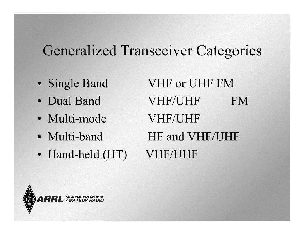
Generalized Transceiver Categories
• Single Band VHF or UHF FM • Dual Band VHF/UHF FM • Multi-mode VHF/UHF • Multi-band HF and VHF/UHF • Hand-held (HT) VHF/UHF
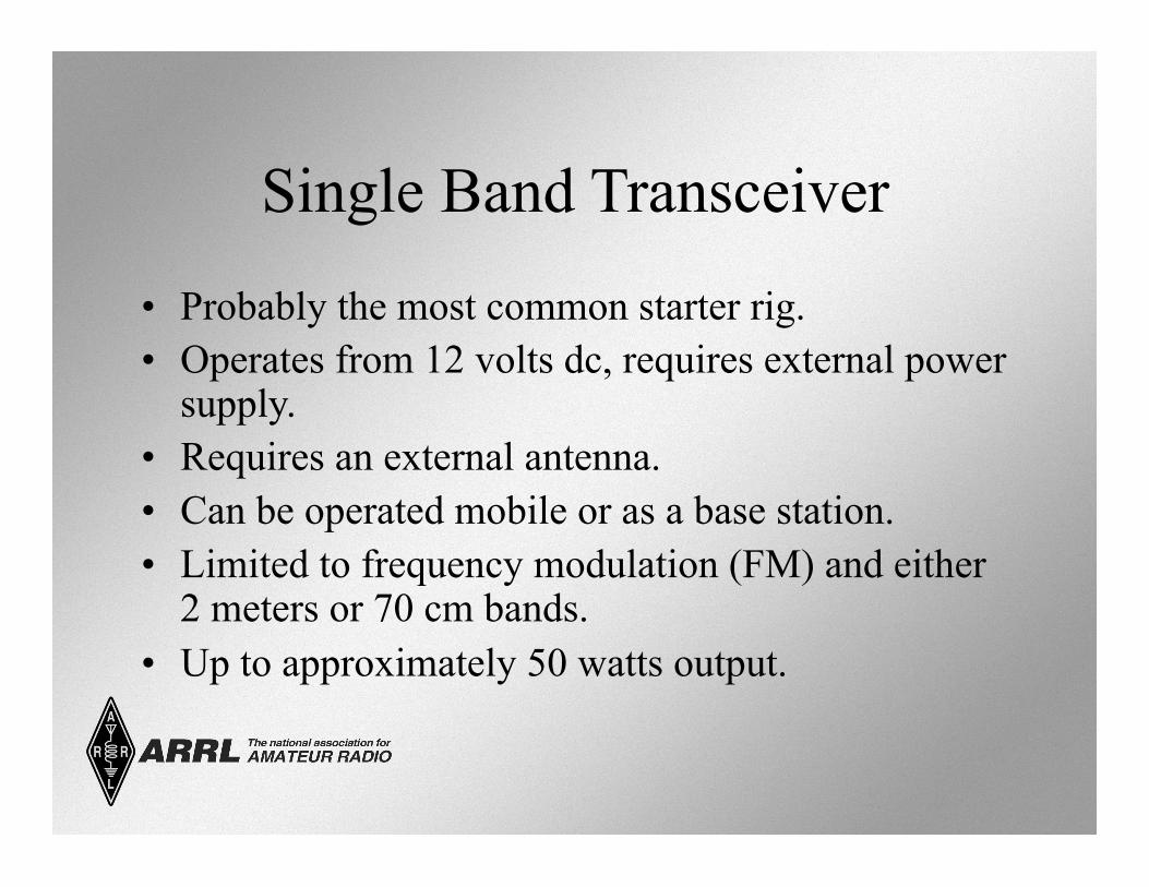
Single Band Transceiver
• Probably the most common starter rig. • Operates from 12 volts dc, requires external power
supply. • Requires an external antenna. • Can be operated mobile or as a base station. • Limited to frequency modulation (FM) and either
2 meters or 70 cm bands. • Up to approximately 50 watts output.
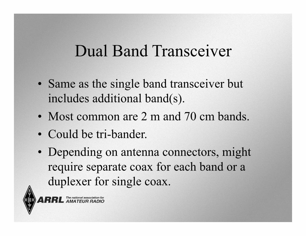
Dual Band Transceiver
• Same as the single band transceiver but includes additional band(s).
• Most common are 2 m and 70 cm bands. • Could be tri-bander. • Depending on antenna connectors, might
require separate coax for each band or a duplexer for single coax.
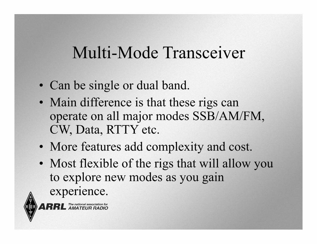
Multi-Mode Transceiver
• Can be single or dual band. • Main difference is that these rigs can
operate on all major modes SSB/AM/FM, CW, Data, RTTY etc.
• More features add complexity and cost. • Most flexible of the rigs that will allow you
to explore new modes as you gain experience.
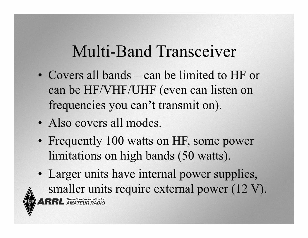
Multi-Band Transceiver • Covers all bands – can be limited to HF or
can be HF/VHF/UHF (even can listen on frequencies you can’t transmit on).
• Also covers all modes. • Frequently 100 watts on HF, some power
limitations on high bands (50 watts). • Larger units have internal power supplies,
smaller units require external power (12 V).
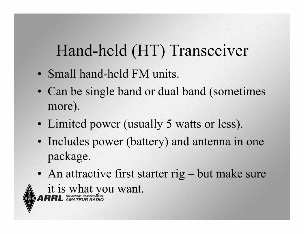
Hand-held (HT) Transceiver • Small hand-held FM units. • Can be single band or dual band (sometimes
more). • Limited power (usually 5 watts or less). • Includes power (battery) and antenna in one
package. • An attractive first starter rig – but make sure
it is what you want.
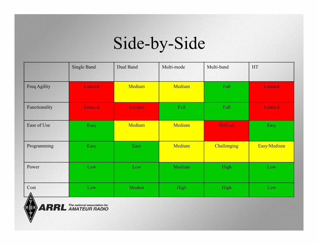
Side-by-Side Single Band Dual Band Multi-mode Multi-band HT
Freq Agility Limited Medium Medium Full Limited
Functionality Limited Limited Full Full Limited
Ease of Use Easy Medium Medium Difficult Easy
Programming Easy Easy Medium Challenging Easy/Medium
Power Low Low Medium High Low
Cost Low Modest High High Low
Rig Vocabulary
• We will now go through some jargon and vocabulary specific to the functions and controls of a transmitter and receiver. – This is a way to discuss how to operate a
transceiver. • These controls, though separate, are
combined in a transceiver.
Transmitter Controls and Functions • Main tuning dial (both TX (trans) and RX
(receive)): – Controls the frequency selection via the
Variable Frequency Oscillator (VFO). – Could be an actual dial or key pad or
programmed channels. – Variable frequency step size (tuning rate,
resolution). – Could have more than one VFO (control more
that one frequency at a time).
Transmitter Controls and Functions
• Mode selector (both TX and RX multi-mode rigs). – AM/FM/SSB (LSB or USB) – CW – Data (RTTY)
• Could be automatic based on recognized band plan.
Transmitter Controls and Functions • Microphone controls
– Gain • How loudly you need to talk to be heard.
– Speech Compressor or Speech Processor • Compacting your speech into a narrow frequency range
to enhance “punch.”
– Too much gain or compression can cause problems. • Splatter • Over-deviation • Over-modulation
Transmitter Controls and Functions
• Automatic Level Control (ALC). – Automatically limits transmitter drive (output
level) to prevent problems associated with too much gain or compression.
• Also can control external power amplifier operation.
Transmitter Controls and Functions
• Transmitter on/off – Push-to-Talk (PTT) – Voice-Operated Transmission (VOX)
• VOX Gain (beefs up your speech) • VOX Delay (reduces sending background beeps) • Anti-VOX (won’t retransmit when your speaker is
live – no echoes)
– Key jack (to plug in your CW keyer)
Transmitter Controls and Functions
• Microphones (Mic) – Hand mics – Desk mics
• Preamplified desk mikes – Speaker-mics – Headsets or boom-sets – Internal mikes
• Speak across the mic, not into the mic.
Transmitter Controls and Functions
• Morse Keys – Straight – Semi-automatic (Bug) – Electronic keyer, paddle
– One paddle dash, one paddle dot – Can be reversed for lefties
Receiver Controls and Functions • AF Gain or Volume
– Controls the audio level to the speaker or headphones.
• RF Gain – Controls the strength of radio signal entering
the receiver. – Used to limit (attenuate) very strong local
signals. – Usually operated in the full-open position.
Receiver Controls and Functions
• Automatic Gain Control (AGC) – Automatically limits the incoming signals during signal
(voice) peaks. • Prevents peaks from capturing the receiver and limiting
reception of lower level portions of the incoming signal.
– Fast setting for CW. – Slow settings for SSB and AM. – Not used in FM because of the type of signal used in
FM.
Receiver Controls and Functions • Squelch
– Turns off audio to speaker when signal is not present. • Used in FM primarily
– Open – allows very weak signals to pass through (along with noise).
– Tight – allows only the strongest signals to pass through.
• Advance the squelch control until the noise just disappears.
Receiver Controls and Functions
• Filters – Band-pass filter
• Used to narrow the width of signal that is passed. • Can attenuate adjacent interference.
– Notch filter • Very narrow filter that can be moved over an interfering signal
to attenuate it.
– Noise blanker or limiter • Limits signal spikes that are frequently associated with random
naturally generated noise.
Receiver Controls and Functions
• Reception and Transmission Meter. – In transmit, indicates output power or ALC or
other functions as selected by switch setting. • In receive - indicates signal strength.
– In “S” units S1 through S9 – S9 is strongest. – Also have dB over S9 to cover very strong
signals.
Receiver Controls and Functions
• Receivers can be limited to ham bands or can cover other parts of the spectrum.
• General coverage receivers cover a wide area of the spectrum and can be used for shortwave listening (SWL).
What is a Repeater?
• Specialized transmitter/receiver interconnected by computer controller.
• Generally located at a high place. • Receives your signal and simultaneously
retransmits your signal on a different frequency (standard offsets: .6 Mhz VHF).
• Dramatically extends line-of-sight range. – If both users can see the repeater site.
A Little Vocabulary First
• Simplex – Transmitting and receiving on the same
frequency. – Each user takes turns to transmit. – Is the preferred method if it works. – National VHF simplex frequency: 146.52
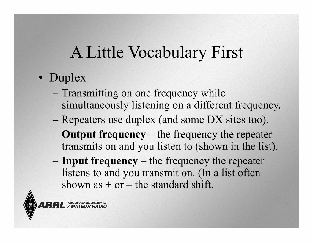
A Little Vocabulary First • Duplex
– Transmitting on one frequency while simultaneously listening on a different frequency.
– Repeaters use duplex (and some DX sites too). – Output frequency – the frequency the repeater
transmits on and you listen to (shown in the list). – Input frequency – the frequency the repeater
listens to and you transmit on. (In a list often shown as + or – the standard shift.
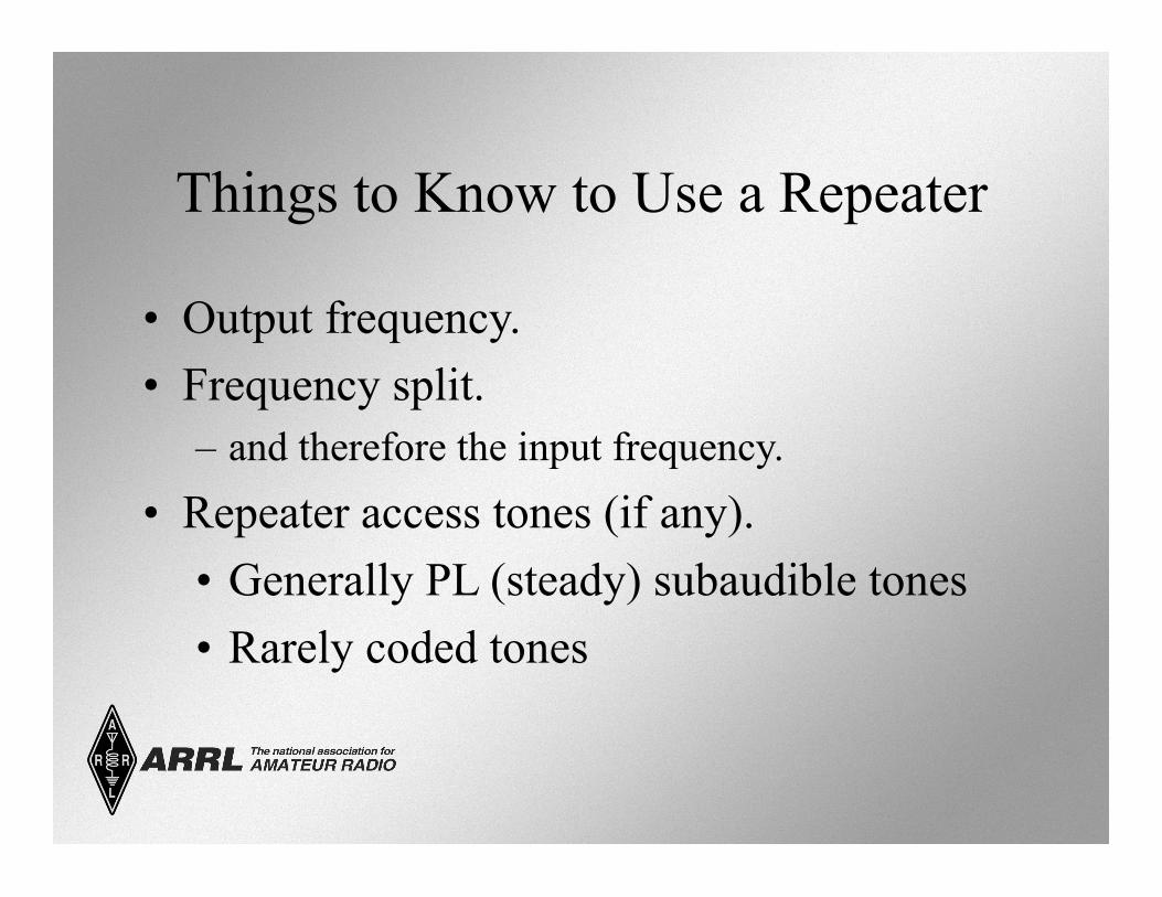
Things to Know to Use a Repeater
• Output frequency. • Frequency split.
– and therefore the input frequency.
• Repeater access tones (if any). • Generally PL (steady) subaudible tones • Rarely coded tones
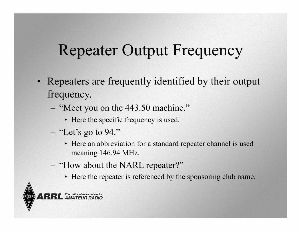
Repeater Output Frequency
• Repeaters are frequently identified by their output frequency. – “Meet you on the 443.50 machine.”
• Here the specific frequency is used.
– “Let’s go to 94.” • Here an abbreviation for a standard repeater channel is used
meaning 146.94 MHz.
– “How about the NARL repeater?” • Here the repeater is referenced by the sponsoring club name.
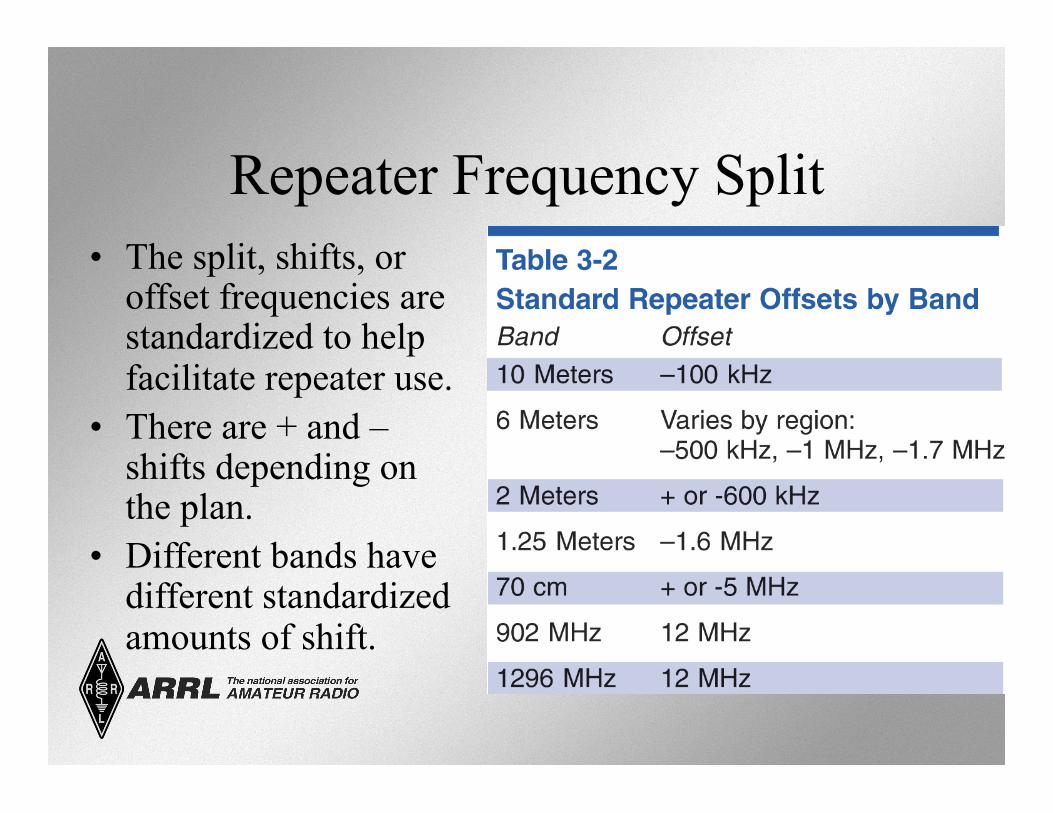
Repeater Frequency Split • The split, shifts, or
offset frequencies are standardized to help facilitate repeater use.
• There are + and – shifts depending on the plan.
• Different bands have different standardized amounts of shift.
Repeater Access Tones • Sometimes multiple repeaters can be accessed at
the same time unintentionally. • To preclude unintentional access, some repeaters
require a special subaudible tone to be present before the repeater controller will recognize the signal as a valid signal and turn on the repeater.
• These tones are called by various names (depending on equipment manufacturer). – CTCSS – PL – Privacy codes or tones
Repeater Access Tones
• Access tones are usually published along with repeater frequencies.
• Could also be announced when the repeater identifies. – “PL is 123.0”
• Tones are generally programmed into the radio along with frequency and offset.
Repeater Controller • Computer that controls the repeater operation.
– Station identification (Morse code or synthesized voice).
• Same ID requirements as you have.
– Time-out protection. • Sometimes called the alligator. • Protects against continuous transmission in the event
of a stuck PTT or long winded hams.
– Courtesy tone – repeater time-out timer reset.
Data Modes
• Connecting computers via ham radio. – Some systems use radio to connect to Internet
gateways. • The bulk of the work is done by specialized
modems or computer software/sound card. – Terminal Node Controller (TNC). – Multiple Protocol Controller (MPC).
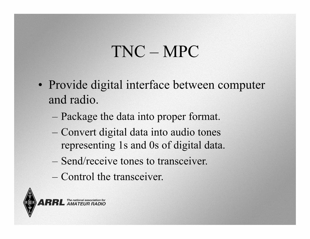
TNC – MPC
• Provide digital interface between computer and radio. – Package the data into proper format. – Convert digital data into audio tones
representing 1s and 0s of digital data. – Send/receive tones to transceiver. – Control the transceiver.
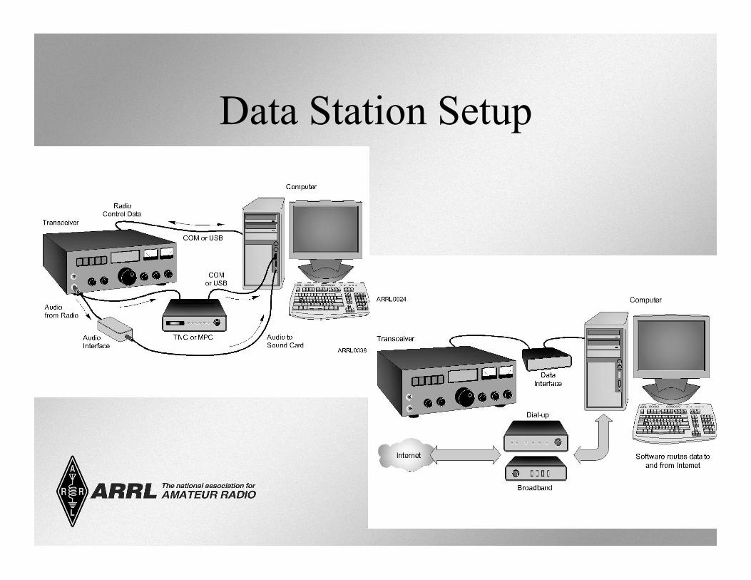
Data Station Setup
Antennas: The Dipole
• Most basic antenna. – Two conductive, equal length parts. – Feed line connected in the middle.
• Total length is ½ wavelength (1/2 l).
• Length (in feet) = 468 / Frequency (in MHz).
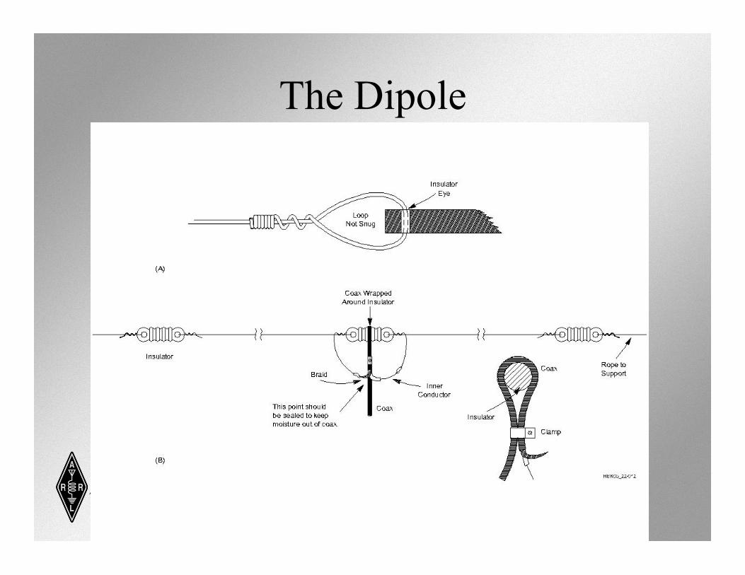
The Dipole
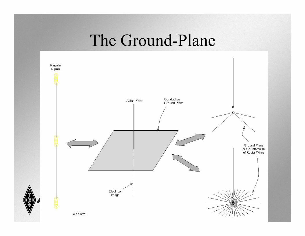
The Ground-Plane
• Simply a dipole that is oriented perpendicular (vertical to the Earth’s surface).
• One half of the dipole is replaced by the ground-plane. – Earth – Car roof or trunk lid or other metal surface. – Radial wires.
• Length (in feet) = 234 / Frequency (in MHz).
The Ground-Plane
Loop Antennas – Dipole Variations
• Quad (4 legs) • Delta (3 legs) • Horizontal (generally 4
legs around a rooftop)
Directional (Beam) Antennas
• Beam antennas focus or direct RF energy in a desired direction. – Gain – An apparent increase in power in the desired
direction (both transmit and receive). • Yagi (rod-like elements – TV antennas). • Quad (square wire loop elements).
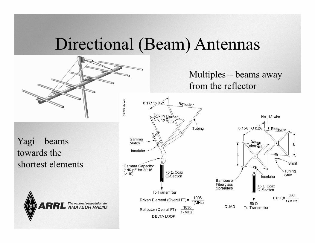
Directional (Beam) Antennas
Yagi – beams towards the shortest elements
Multiples – beams away from the reflector
Directional (Beam) Antennas • All beam antennas have parts called elements.
– Driven element connected to the radio by the feed line.
– Reflector element is on the back side. – Director element is on the front side toward the
desired direction.
Coax Feed Lines
• RG-58 • RG-8 • RG-213 • RG-174 • Hardline • (differ in thickness, resistance to
UV or outgassing)
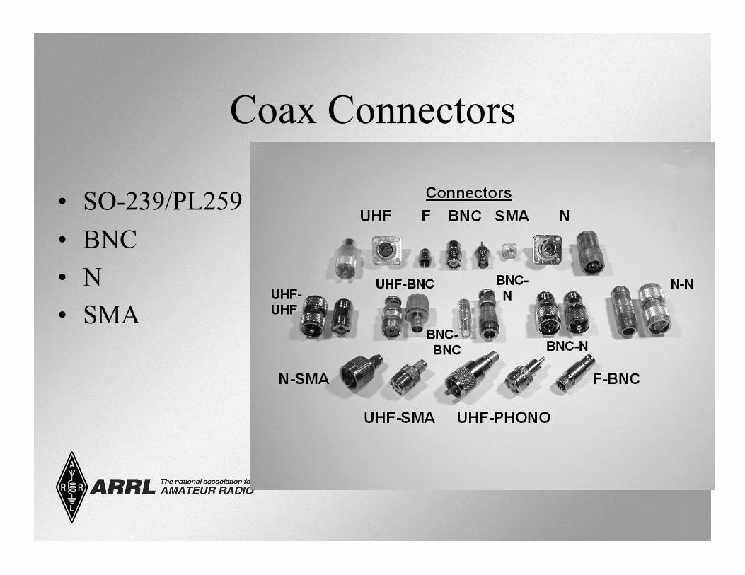
Coax Connectors
• SO-239/PL259 • BNC • N • SMA
Feed Line Devices • Balun (Balanced to Unbalanced….
Needed for ladder lines) • Duplexer (one antenna, two feeds) • Antenna switches • SWR meter • Antenna analyzer • Antenna tuners
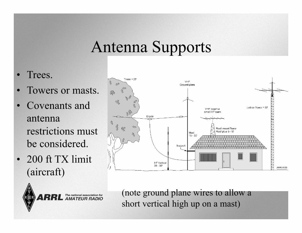
Antenna Supports • Trees. • Towers or masts. • Covenants and
antenna restrictions must be considered.
• 200 ft TX limit (aircraft)
(note ground plane wires to allow a short vertical high up on a mast)
Power Supplies
• Most modern radio equipment runs from 12 volts dc. • Household current is 120 volts ac. • Power supplies convert 120 volts ac to 12 volts dc.
– 13.8 volts dc is the common voltage you will see. – This is the charging voltage for motorized vehicles. – Most equipment can handle 11-14 V
Power Supply Ratings Voltage and Current
• Continuous duty – how much current can be supplied over the long term.
• Intermittent duty – how much surge current can be supplied over the short term.
• Regulation – how well the power supply can handle rapid current changes.
Types of Power Supplies • Linear:
– Transformers – Heavy (physically) – Heavy duty current – Expensive
• Switching: – Electronics instead of transformers – Light weight and small – Not as robust – Less expensive
Inverters and Generators
• Inverters convert dc into ac. – Square, triangle, sine-wave inverters. – Can be choppy
• Generators create ac. – Gas powered. – Various voltage and current ratings. – Special precautions.
Batteries • Create current through a chemical reaction.
– Made up of individual cells (approximately 1.5 volts per cell) connected in series or parallel.
• Battery types. – Disposable. – Rechargeable. – Storage.
• Power capabilities rated in Ampere-hours. – Amps * time. (longer usage if you use less power)
Battery Charging • Some batteries can be recharged, some cannot. • Use the proper charger for the battery being
charged. • Batteries will wear out over time. • Best if batteries are maintained fully charged.
– Over-charging will cause heating and could damage the battery.
• Some batteries (lead-acid) may release toxic (or explosive) fumes during charging so require ventilation.
Handheld Transceivers • Single, dual and multi-band versions (with
increasing cost and complexity). – Some have expanded receiver coverage (wide-
band receive: “DC to daylight”). • Very portable and self-contained.
– Internal microphone and speaker. – Rubber duck antenna (short). – (can attach to external mag-mount antenna on car) – Battery powered.
Nice to have handheld accessories
• Extra battery packs. • Drop-in, fast charger. • Extended antenna. • External microphone and speaker. • Headset.
Radio Frequency Interference (RFI)
• Unwanted, unintentional signals from some electronic device that interferes with radio wave reception.
• You can prevent creating RFI by operating your transmitting equipment properly.
RFI Mitigation • Filters
– Filters attenuate (reduce) interfering signals – but do not totally eliminate them.
• High-pass –generally on the receive side. (e.g. filter out car ignition noise) • Low-pass – generally on the transmit side. • Band-pass – used within most radio
equipment.
Types of RFI
• Direct detection – offending signals get into the electronics circuits to cause interference.
• Overload – strong signal that overwhelms the weaker, wanted signal.
• Harmonics – even multiples of the offending signal that coincide with the wanted signal.
Cable TV Interference
• Usually the result of broken shielding somewhere in the cable. – Loose connections. – Broken connections. – Corroded connections.
• Usually solved by proper cable maintenance by cable supplier. – If the subscriber is a legitimate subscriber.
Noise Sources • Electrical arcs (motors, thermostats, electric
fences, neon signs). • Power lines. (NEW concern: BPL =
internet on power lines) • Motor vehicle ignitions. • Motor vehicle alternators. • Switching power supplies. • Computers, networks, and TV sets. • Hospital equipment
Dealing with RFI
• Make sure you operate your equipment properly.
• Eliminate interference in your own home first.
Dealing with RFI
• Take interference complaints seriously. • Make sure that you’re really not the cause
(demonstrate that you don’t interfere within your own home).
• Offer to help eliminate the RFI, even if you are not at fault.
• Consult ARRL RFI Resources for help and assistance.
What the Rules Say
• RFI from and to unlicensed devices is the responsibility of the users of such devices
• Bottom line – If your station is operating properly, you are protected against interference complaints
• BUT – Be a good neighbor because they may (probably) not be familiar with Part 15 rules and regulations