Embed Size (px)
Citation preview
Primary Stemless Shoulder System
Technique GuideTM

2
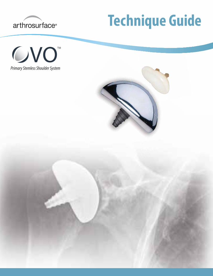
1. Beachchair position
(tilt back to 45 degree angle).
2. Short deltopectoral incision (from
coracoid tip to pectoralis major insertion).
3. This incision is utilitarian and can be
converted to an extensile approach if
necessary.
4. Develop skin flaps over pectoralis
& deltoid.
5. Develop deltopectoral interval.
a. The cephalic vein may go either
medially or laterally. Lateral retraction
of the cephalic vein can be beneficial
because it preserves the venous
outflow from the deltoid.
b. Identify coracoid tip.
c. Identify pectoralis major insertion.
6. Release subdeltoid and subacromial
adhesions. Abducting the shoulder in
order to relax the deltoid facilitates
this step.
7. Retract the deltoid and pectoralis major
muscles. This step is facilitated by the use
of a blunt, multi-pronged self-retaining
retractor.
8. Identify and develop the lateral border of
the conjoined tendon. This step is assisted
by flexion of the shoulder, which relaxes
the conjoined tendon & facilitates exposure.
9. Retract the conjoined tendon medially.
Take care to not injure the musculo-
cutaneous nerve. A blunt, non self-retaining
retractor under the conjoined tendon
facilitates exposure while minimizing risk
to the nerve.
10. Remove bursa from atop the subscapularis
insertion.
11. Identify the anterior humeral circumflex
vessels, which define the inferior aspect of
the subscapularis. As needed, a 90 degree
pediatric clamp is a useful tool to isolate
the vessels. If necessary, a suture can be
used to ligate the vessels.
12. Identify and protect axillary nerve. The
axillary nerve lies deep to the anterior
humeral circumflex vessels and superficial
to the subscapularis muscle at the level of
the glenoid. A rubber vessel loop can be
used to protect/isolate the axillary nerve,
if necessary.
13. Incise the subscapularis. Use of a needle
tip electrocautery 1 cm lateral to the
musculotendinous junction facilitates
this step.
a. Patients with anterior-inferior
instability may be candidates for
capsular shift and/or Bankart repair.
In such cases, begin the subscapularis
incision inferiorly and proceed
superiorly in order to best differentiate
the tendon from the underlying
capsule.
b. Alternatively, the subscapularis and
capsule can be incised in one layer.
c. Alternatively, the lesser tuberosity
may be osteotomized with a sharp,
1 inch straight osteotome. This will
allow bone to bone healing at the
conclusion of the procedure.
Anterior Deltopectoral Approach
3
14. Place #2 sutures using a Mason-Allen
configuration into the edge of the
subscapularis to help retract the tendon
and for definitive repair at the conclusion
of the procedure.
a. A medium Cobb elevator and/or
Metzenbaum scissors help to bluntly
develop the layer between the
subscapularis and the joint capsule.
It is important to separate the
subscapularis and the capsule medial
to the joint line in order to address (if
necessary) a Bankart lesion.
15. Release the rotator interval capsule
between the upper border of the
subscapularis and the anterior edge
of the supraspinatus.
16. Incise the glenohumeral joint capsule
along the anatomic neck with electrocautery.
17. If necessary, place a blunt “Cobra” or
Hohman retractor between the axillary
nerve and subscapularis/capsule in order
to protect the axillary nerve.
18. Release the glenohumeral capsule from its
insertion on the anatomic neck of the
humerus anteriorly and inferiorly. External
rotation and flexion of the shoulder
facilitates capsular release and improves
humeral head exposure.
19. Release the capsule completely off the
anatomic neck until adequate exposure of
the humeral head defect is achieved.
a. Posterior humeral head defects can
be successfully addressed with the
Arthrosurface® HemiCAP® implant
using an anterior deltopectoral
exposure. Inferior capsular release
from the anatomic neck of the
humerus is an important step. Take
care to release the capsule directly
off the bone in order to minimize risk
to the axillary nerve. Blunt retractors
(i.e. Cobra or Hohman) placed
between the inferior capsule and the
axillary nerve can also minimize
neurological injury.
20. Place a humeral head retractor (i.e.
Fukuda) to evaluate the glenoid and
check for a Bankart lesion.
21. Address any glenoid pathology as
indicated.
22. Insert Arthrosurface® OVO™ implant
as indicated.
23. Repair glenohumeral joint capsule and
subscapularis as indicated.
24. Closure utilizing accepted practices.
ason-Allen
e of the
ct the tendon
the conclusion
ator and//or
help to blblununtltltlyyyyyy
ween the
e joint capsule.
arate the
e capsule medial
er to address (if
esion

4
Description
The OVO™ Contoured Articular Prosthetic incorporates an articular component and a
taper post component that mate together via a morse taperinterlock to provide
stable and immobile fixation of the implant and stress bearing contact at the
bone/prosthetic interface.
Materials
Articular Component: Cobalt-Chronium Alloy (Co-Cr-Mo)
Undersurface Coating: Titanium (CPTi)
Taper Post: Titanium Alloy (Ti-6Al-4V)
Indications
For the reconstruction of painful and/or severely disabled shoulder joints resulting from
post-traumatic degenerative disease or avascular necrosis. The humeral head and neck
should be sufficient bone stock to support loading. The rotator cuff should be intact or
reconstructable. The device is a single use implant intended to be used with bone cement.
OVO™ System Components
• Cobalt Chrome Component
(Ovoid shapes, 7 offset choices)
• Ti Plasma Spray Undercoating
• Morse Taper:
Interlocks the two components
• Titanium Fixation Component
(Cannulated, Bead blasted)
Chapter One (Pages 5-10)
OVO™ Primary Stemless Shoulder System

5
1. Remove all osteophytes around the humeral head using
a 3/4 inch osteotome and/or rongeur. There should be a
smooth transition from the humeral neck to the humeral
head. Use the Reduction Trial to ascertain that all
osteophytes have been adequately removed.
2. Place the appropriate Mapping Templates over the
articular surface and map the surface in both superior/
inferior and anterior/posterior planes. Utilize the
Templates to obtain the superior/inferior diameter
and anterior/posterior diameter that best replicate the
anatomy. Use the Sizing Card to record the diameters.
The Surface Reamer will be selected based on the
anterior/posterior value. Place the Reduction Trial onto
the humeral head to verify the Reduction Trial size and
placement.
Note: The Surface Reamer and/or Drill Guide may also
be used to assess correct pin location.
3. Locate the Guide Pin on head using option 1, 2, or 3 (see
below). Place the 2.5 mm Guide Pin into a cannulated
powered drill and secure at the etch marking on the
Guide Pin. Advance the Guide Pin into the bone with
care to avoid penetrating through the lateral humeral
cortex.
Surgical Technique
Chapter One: OVO Primary Stemless Shoulder System
Options:
1 2 3
Drill Guide Reduction Trial Shaft & Reamer

6
4. Using a cannulated powered drill, advance the Centering
Shaft over the Guide Pin until the distal shoulder of the
Centering Shaft marking is at the height of the articular
surface. The Centering Shaft can be placed slightly proud
to the surface to compensate for a flattened humeral
head. The shoulder of the Centering Shaft sets the peak
height representing the location of the crown of the
implant.
5. Using the OVO Reamer that matches the anterior/
posterior value, advance the OVO Reamer over the
Centering Shaft until it reaches the stop on the
Centering Shaft. If using an Inlay Glenoid Component,
repeat using the Crown Reamer to provide additional
access for the Glenoid instruments. Be sure the OVO
Reamer is started before engaging the humeral head.
6. Place the appropriate Reduction Trial onto the prepared
humeral surface and perform a range of motion
evaluation. Assemble the Guide Handle onto the
Preparation Trial and secure the Preparation Trial into
position using at least two Short Guide Pins. The pins
are critical, keeping the trial stable so that the correct
orientation of the final implant can be maintained.

7
8. Advance the Step Drill over the Pilot Drill
until the proximal shoulder of the Step Drill is
even with the height marker on the Preparation
Trial collar.
9 . Advance the Tap over the Pilot Drill until the
laser mark on the Tap is even with the height
marker on the Preparation Trial collar. Remove
the Tap and Pilot Drill.
7. With the Preparation Trial fixed in place,
insert the Pilot Drill through the center of the
Guide Handle and advance until the laser mark
indicated on the Pilot Drill meets the back of the
handle. Leave the Pilot Drill in place and unscrew
and remove the Guide Handle.
Laser Mark
Laser Mark
Preparation
Trial Collar
Chapter One: OVO Primary Stemless Shoulder System
8
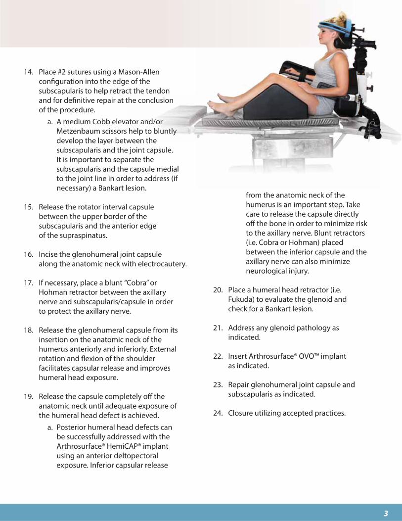
11. Use the Alignment Gauge to ensure that the Taper
Post is seated at the proper depth. The Alignment
Gauge is inserted into the Preparation Trial. The
Gauge should meet resistance from the Taper Post
and be flush with the edge of the Preparation Trial.
If the Gauge is sitting proud then leave it in place
and use the Hex Driver to rotate it flush with the
Trial. If the Alignment Gauge does not connect
with the Taper Post then the Taper Post has been
inserted too far into the bone. To address this
situation, rotate the Taper Post counterclockwise
and check placement with the Alignment Gauge.
Place the Reduction Trial into the defect that
matches the offset profile of the chosen OVO
Articular Component. Confirm the fit of the
Reduction Trial so that it is congruent with the
edge of the surrounding articular surface or slightly
recessed. If the Reduction Trial is proud at the edge
of the articular cartilage, re-ream the area until the
Reduction Trial is flush or slightly recessed.
IF PERFORMING THE GLENOID:
Proceed to Step 1 in Chapter Two
10. Prior to inserting the Taper Post, thoroughly
cleanse the pilot hole of any debris and inject the
cement in a retrograde fashion from the end of the
hole upwards. Load the Taper Post into the distal
end of the Guide Handle and attach the Guide
Handle to the Preparation Trial. Place the Hex
Driver through the Guide Handle and advance the
Taper Post until the stop in the shaft of the Hex
Driver comes in contact with the back of the Guide
Handle. Be careful NOT to advance the screwdriver
once it contacts the handle as it will move the screw
in and away from the Morse Taper.

9
13. Firmly mallet the Impactor until the OVO™
Component is completely seated onto the
Taper Post.
12. Prior to placing the OVO Component on the
Implant Holder, make sure that sufficient suction
is present to hold the device onto the distal suction
cup. Align the OVO Component on the Implant
Holder with the etch mark inline with the superior
offset of the OVO Component. Use the Implant
Holder mark to align the implant in the proper
orientation and insert onto the taper of the Taper
Post.
Matching OVO™ Implant Diameters to Appropriate Glenoid
48 x 448H02-4844
50 x 468H02-5046
52 x 488H02-5248
SingleG203-2015
DoubleG203-2520
More CurvedGlenoids
OVO™ Diameters
54 x 508H02-5450
56 x 528H02-5652
58 x 548H02-5854
SingleG203-2010
DoubleG203-2515
Less CurvedGlenoids
46 x 428H02-4642
Chapter One: OVO Primary Stemless Shoulder System
10
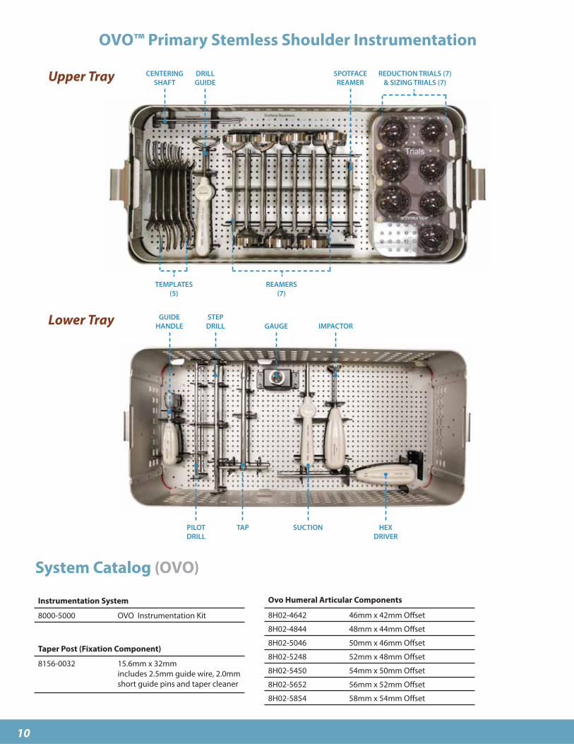
OVO™ Primary Stemless Shoulder Instrumentation
System Catalog (OVO)
Instrumentation System
8000-5000 OVO Instrumentation Kit
Taper Post (Fixation Component)
8156-0032 15.6mm x 32mm
includes 2.5mm guide wire, 2.0mm
short guide pins and taper cleaner
CENTERING
SHAFT
TEMPLATES
(5)
DRILL
GUIDE
REAMERS
(7)
REDUCTION TRIALS (7)
& SIZING TRIALS (7)
SPOTFACE
REAMER
GUIDE
HANDLE
PILOT
DRILL
STEP
DRILL
TAP
GAUGE
SUCTION
IMPACTOR
HEX
DRIVER
Ovo Humeral Articular Components
8H02-4642 46mm x 42mm Offset
8H02-4844 48mm x 44mm Offset
8H02-5046 50mm x 46mm Offset
8H02-5248 52mm x 48mm Offset
8H02-5450 54mm x 50mm Offset
8H02-5652 56mm x 52mm Offset
8H02-5854 58mm x 54mm Offset
Upper Tray
Lower Tray

11
Description
The Contoured Articular Prosthetic incorporates an articular resurfacing
component and a taper post component that mate together via a morse taper
interlock to provide stable and immobile fixation of the implant and stress bearing
contact at the bone/prosthetic interface.
The Inlay glenoid component is intended to interface and articulate with the
humeral component when both articular surfaces of the joint are affected.
Materials
Glenoid Component: Ultra High Molecular Weight Polyethylene (UHMWPE)
Indications
For the reconstruction of painful and/or severely disabled shoulder joints resulting from
post-traumatic degenerative disease or avascular necrosis. The humeral head and neck
should be sufficient bone stock to support loading. The rotator cuff should be intact or
reconstructable. The device is a single use implant intended to be used with bone cement.
Inlay Glenoid System Components
• Ultra High Molecular Weight Polyethylene (UHMWPE)
• Inlay design
• Labrum preserving
• Two offset choices per component
Single
Partial Glenoid Component
Double
Full Glenoid Component
Chapter Two (Pages 11-15)
Inlay Glenoid Replacement

12
1. Use the Drill Guide to locate the intended implant position
on the glenoid surface. Position the Drill Guide central to
the inferior aspect of the glenoid lesion. Place the tip of the
Guide Pin into the Drill Guide and advance the Guide Pin
into the bone to the depth of the single etch mark using a
cannulated power drill. The Guide Pin will be positioned
slightly offset posteriorly. This is normal for the system as the
Reamer begins to cut anterior first.
2. Introduce the Inferior Glenoid Reamer over the Guide
Pin and carefully advance under power until the Guide
Pin stops at the back of the Proximal Reamer window. Be
sure to ream and visually check the depth of the reamer
using the Inferior Glenoid Trial to help avoid posterior wall
blowout.
Surgical Technique
Chapter Two: Inlay Glenoid Replacement
* 30º
* This sets up angled
approach for
spherical reaming
* Angled approach
& ream creates a
spherical socket
* 30º

13
3. Position the slotted Inferior Glenoid Trial over the
Guide Pin and confirm that the trial is flush or slightly
recessed to the remaining glenoid fossa. Position the
Inferior Glenoid Trial and place the Flexible Peg Drill
into the central hole. Advance the Flexible Peg Drill to
the stop to make the tunnel for the peg of the Glenoid
Component.
*If using the Single Glenoid Component only,
proceed to Step 7
4. If using the larger Double Glenoid, place the Inferior
Glenoid Trial in its proper orientation. Advance the
Guide Pin into the superior hole of the trial and drill
to the proximal line of the double etch mark using a
cannulated powered drill.
5. Introduce the Superior Glenoid Reamer over the
Guide Pin and advance under power until the Superior
Glenoid Reamer stops at the back of the Proximal
Reamer window. Be sure to ream with caution and
check the depth of the reamer to avoid posterior
wall blowout. Position the Double Glenoid Trial and
advance the Flexible Peg Drill into both central holes
of the Trial to make bone tunnels for the Double
Glenoid Component pegs.
Flexible Peg Drill

14
6. Position the Double Glenoid Trial and confirm that
the trial is flush or slightly recessed to the remaining
glenoid fossa. Advance the Peg Drill to perform bone
cuts for the Glenoid Component superior peg. Place
the Sizing Trial into the defect that matches the
offset profile of the Glenoid Implant. Confirm the
fit of the Sizing Trial so that it is congruent with the
edge of the surrounding articular surface or slightly
recessed. If the Sizing Trial is proud at the edge of the
articular cartilage, re-ream the area until the Sizing
Trial is flush or slightly recessed.
7. Use the Angled Gouge and mallet to create
several cement channels around the periphery
of the glenoid fossa to aid with cement fixation.
8 . Apply a small amount of low-viscosity bone
cement into the prepared glenoid surface. Using
the Cement Finger Cap, apply pressure to the
cement in the glenoid fossa to make sure the
cement fills the peg holes and gouge channels.
9 . Place the Inlay Glenoid Implant into position
and use the Glenoid Impactor to secure the
glenoid implant into position making sure
the implant fits flush or slightly recessed to
the surrounding glenoid fossa. The Glenoid
Impactor is created by sliding the Slotted
Impactor Tip over the end of the Angled
Gouge. Maintain firm pressure on the implant
until the bone cement sets. Remove any excess
bone cement.
Angled Gouge
Cement Finger Cap
Chapter Two: Inlay Glenoid Replacement
TipAngled Gouge Impactor

15
Inlay Glenoid Replacement Instrumentation
System Catalog
CEMENT
FINGER CAP
UNIVERSAL
INSTRUMENT HANDLE
ETCHED
GUIDEWIRE
INFERIOR
REAMER
ANGLED
GOUGE
FLEXIBLE
PEG DRILL
SUPERIOR
GLENOID REAMER
ETCHED
GUIDEWIRE
Glenoid Instrumentation System
G007-1400 2.0mm Glenoid Guide Pin (sterile)
G000-0100 Inferior Glenoid Instrument Kit
(sterile, disposable)
G000-0200 Superior Glenoid Instrument Kit
(sterile, disposable)
Inlay Glenoid Component
Inferior Glenoid Component - Single
G203-2010 19mm x 20mm Glenoid Comp. 1.0mm Offset (58-54mm)
G203-2015 19mm x 20mm Glenoid Comp. 1.5mm Offset (52-46mm)
Superior Glenoid Component - Double
G203-2515 20mm x 25mm Glenoid Comp. 1.0mm Offset (58-54mm)
G203-2520 20mm x 25mm Glenoid Comp. 1.5mm Offset (52-46mm)
Matching Ovo
Head Diameters
Inferior Tray
Superior Tray
INFERIOR
REDUCTION TRIALS(Packaged sterile
separately in disposable
instrument box
with suction)
DRILL
GUIDE
GUIDES
(L,R)
REDUCTION TRIALS
IMPACTOR

28 Forge Parkway • Franklin, MA 020381 508 520 3003
fax: 1 508 528 3785
For more information, visit our website:
www.arthrosurface.com
This product is covered by one or more of U.S. Patent Nos. 6,520,964;
6,610,067; 6,679,917 and other patents pending.
Arthrosurface, Inc. All rights reserved.
Printed in U.S.A.
This pamphlet and information is intended for markets where regulatory approval has been granted.
PN 3001-3009 REV A
Warnings
Improper selection, placement, positioning, alignment,
and fixation of the implant components may reduce the
service life of the prosthetic components. Inadequate
preparation and cleaning of the implant components
mating surfaces may result in improper fixation of the
device. Improper handling of the implants can produce
scratches, nicks or dents that may have adverse clinical
effects on mating joint surfaces. Do not modify im-
plants. The surgeon shall be thoroughly familiar with the
implants, instruments, and surgical technique prior to
performing surgery.
When defining offsets of articular surfaces, care should
be taken to ensure that instruments are properly aligned.
When placing implant, carefully trim articular cartilage
debris or osteophytes around margin of implant. Remove
bone particles and lavage thoroughly. To ensure me-
chanical interlock of the Taper Post and implant, care-
fully clean Taper Post taper with provided instruments.
All drilling or reaming should be done at slowest speeds
possible with vigorous lavage to minimize heat effects to
adjacent bone and cartilage tissues.
Accepted practices in post operative care should be
used. The patient is to be instructed and monitored
to ensure a reasonable degree of compliance to post
operative instructions and activity restrictions. Excessive
activity, impact, and weight gain have been implicated in
the reduction of the benefit and service life of prosthetic
devices.
Precautions
OVO implants are intended to be fitted and installed
with the OVO instrument set. Use of instruments from
other systems may result in improper implant selection,
fitting, and placement which could result in implant
failure or poor clinical outcome. The OVO instrument set
should be regularly inspected for any signs of wear or
damage. Do not reuse implants.
Possible Adverse Effects
1) Material sensitivity reactions. Implantation of
foreign material in tissues can result in histological
reactions. Particulate wear debris and mild tissue
discoloration from metallic components have
been noted in other prosthetic devices constructed
of similar materials. Some types of wear debris
have been associated with osteolysis and implant
loosening.
2) Infection or allergic reaction.
3) Loosening, migration or loss of fixation of implant.
4) Fretting and crevice corrosion can occur at the
interface between the implant components.
5) Fatigue fracture of the implants as a result of
bone resorption around the implant components.
6) Wear and damage to the implant articulating
surface.
7) Wear and damage to the adjacent and opposed
articular cartilage surfaces or soft tissue support
structures.
8) Intraoperative or postoperative bone fracture.