Embed Size (px)
Citation preview

Pelvic Implants and Instruments.A dedicated system for reconstructivepelvic and acetabular surgery.
Technique Guide

Image intensifier control
WarningThis description alone does not provide sufficient background for direct use of theproduct. Instruction by a surgeon experienced in handling this product is highlyrecommended.
Reprocessing, Care and Maintenance of Synthes InstrumentsFor general guidelines, function control and dismantling of multi-part instruments,please refer to: www.synthes.com/reprocessing

Pelvic Implants and Instruments Technique Guide Synthes 1
Table of Contents
Introduction
Surgical Technique
Product Information
Pelvic Implants and Instruments 2
Implant Specifications 4
AO Principles 6
Indications 7
Instruments – Standard 8– Retractors 10– Reduction 12
Plate Contouring 14– In-situ Plate Contouring 16
Fracture Fixation – A. Pubic Symphysis Fractures 18– B. Iliac Fractures 22– C. Acetabulum Two Column Fractures 28
Plates 38
Screws 43
Instruments 44
Optional Implants 51
Optional Screws 53
Optional Instruments 54
Other Available Pelvic Instruments and Implants 59from Synthes

2 Synthes Pelvic Implants and Instruments Technique Guide
Pelvic Standard Instrument SetThe Pelvic Instrument Set has a wide range of standard instruments for screw insertion, plate adaptation (bendinginstruments) and fixation during reduction for preliminaryand definitive stabilization of pelvic and acetabular fractures.
The complex anatomy of the pelvic ring and acetabulum involve complex surgical exposures and demands exactanatomical reduction to achieve positive functional results.
The AO and Synthes took this into consideration in develop-ing the Pelvic Implant and Instrument Sets.
Pelvic Implants and Instruments.A dedicated system for reconstructivepelvic and acetabular surgery.
Essential equipment for the surgicaltreatment of pelvic fractures
The Pelvic Implant and Instrument Sets contain a wide rangeof implants, reduction instruments, retractors and instru-ments for screw and plate fixation for the operative treat-ment of pelvic and acetabular fractures. All implants areavailable in 316L implant stainless steel, sterile and non ster-ile packaged.
Reconstruction Plate and Screw SetThe pelvic and acetabular low profile implants offer pre-shaped plate designs. Additional trays with locking compres-sion, wide angle (acetabular) and J-plates (pelvic brim) arealso available. All plates can be three-dimensionally con-toured allowing them to be closely adapted to pelvic bonesurfaces. Bending templates allow for easy manual adapta-tion of the plates.

Pelvic Implants and Instruments Technique Guide Synthes 3
Pelvic Retractor SetA wide range of retractors (pelvic, Hohmann, sciatic nerveand malleable) within the Pelvic Retractor Set provide moreoptions to aid the surgeon in achieving good visibility withinthe chosen approach.
Pelvic Reduction Instrument SetThe pelvic reduction forceps and other reduction instrumentswithin the Pelvic Reduction Instrument Set are designed toaid the surgeon with fracture reduction of pelvic injuries.

Reconstruction PlatesOccasionally, pelvic osteosyntheses can be carried out usingscrews alone, but in the majority of cases lag screw fixationsmust be supplemented by one or more plates.
The bone surfaces in the pelvic region have a very complextopography. In order to achieve accurate fixation, the platesshould be contoured to the bone surface. Poorly contouredplates can lead to fracture displacement when the screws arefully tightened through the plate.
The design of the reconstruction plates allow for contouringin all three planes.
Coaxial combi-holes inlocking platesAllow the use of lockingscrews or cortex screws in thesame round conical plate hole
Implant Specifications
– Profile: 3.7 mm– Screw angulation: up to 30°– Holes: 3 – 20 (straight)– Allow the use of cortex screws
and/or pelvic cortex screws 3.5 mm
3.5 mm Low Profile Reconstruction Plates 3.5 mm Wide Angle Reconstruction Plates
4 Synthes Pelvic Implants and Instruments Technique Guide
– Low profile: 2.7 mm– Screw angulation: up to 25°– Holes: 3 – 20 (straight),
6 – 16 (curved), 10 – 16 (J-shaped) – Low Profile Reconstruction Plate,
curved:– Available in two radii (88 mm
and 108 mm) to fit the average pelvis of a female or male, respectively
– Allows the use of cortex screws and/or pelvic cortex screws 3.5 mm
– Low Profile Reconstruction Plate, J-shaped: hybrid of curved andstraight:– One leg of the plate is straight,
while the other leg is bent with aradius of 88 mm
– Left and right– Fits along pelvic brim, from
the pubic rami (curved part of theplate) to the SI joint (straight endof the plate)

Low profile androunded edgesMinimizes soft tissue irritation
Uniform cross-sectionImproved contourability
– Profile: 3.7 mm– Screw angulation:
up to 12° (cortex screws)– Holes: 3 – 20 (straight),
10 – 16 (J-shaped)– Features coaxial combi-holes (this
means the plate can be used withstandard cortex screws 3.5 as well aswith 3.5 locking screws)
– Fits the anatomy of the pubic symphysis
– Coaxial combi-holes accept 3.5 locking screws as well as stan-dard/pelvic cortex screws (3.5)
– Radius of 60 mm– Reinforced midsection of plate – 3 small holes in midsection can be
used to attach sutures – 4 versions:
4 coaxial combi-holes6 coaxial combi-holes2 DCU holes and 2 coaxial combi-holes*2 DCU holes and 4 coaxial combi-holes*
*DCU (Dynamic Compression Unit)
– Reduces and stabilizes small bonefragments that are too small forscrews.
– Can be used individually or with a3.5 mm reconstruction plate.
– Pre-bent convex shape with twosharp spikes on the bottom surface.Reduction is achieved by sinkingspikes into small fragments whiletightening a screw through one ofthe screw holes.
– Convex shape for better bone reten-tion. Small fragments are preloadedonce a screw is inserted and allowsit to conform better to bony, unevensurfaces.
– Allows the use of cortex screws and/or pelvic cortex screws 3.5 mm
3.5 mm Locking ReconstructionPlates
3.5 mm Pubic Symphysis Plates 3.5 mm Spring Plate
Pelvic Implants and Instruments Technique Guide Synthes 5

AO Principles
In 1958, the AO formulated four basic principles, whichhave become the guidelines for internal fixation:1, 2 Thoseprinciples as applied to the Pelvic Implants and Instrumentsare:
Anatomic reductionFracture reduction and fixation to restore anatomical relationships.
Stable fixationStability by screw only or screw and plate fixation, as the personality of the fracture and the injury requires. The products provide purchase for required compression and stability.
Preservation of blood supplyPreservation of the blood supply to soft tissue and bone bycareful handling and atraumatic surgery. Use of surgical tech-nique that minimizes disruption of soft tissue and preservesvascular blood flow for bone healing.
Early, active mobilizationEarly and safe patient mobilization. The implants, combinedwith AO technique, provide stable fracture fixation with minimal trauma to vascular supply. Plate features combinedwith AO technique create an environment for bone healing,expediting return to function.
6 Synthes Pelvic Implants and Instruments Technique Guide
1 Müller ME, Allgöwer M, Schneider R, Willenegger H (1995) Manual of Internal Fixation. 3rd, expanded and completely revised ed. 1991. Berlin, Heidelberg, New York: Springer
2 Rüedi TP, Buckley RE, Moran CG (2007) AO Principles of Fracture Management. 2nd expanded ed. 2002. Stuttgart, New York: Thieme

Indications
Symphysis fractures– 3.5 mm Pubic Symphysis Plates
Pelvic brim fractures– 3.5 mm Low Profile Reconstruction Plates
– Straight Plates– Curved Plates (88 mm radius, 108 mm radius)– J-Plates
– 3.5 mm Locking Reconstruction Plates– Straight Plates– J-Plates
– 3.5 mm Wide Angle Reconstruction Plates– Straight Plates
Ilium/Iliac wing fractures – 3.5 mm Low Profile Reconstruction Plates
– Straight Plates – Curved Plates (88 mm radius, 108 mm radius)
– 3.5 mm Locking Reconstruction Plates– Straight Plates
– 3.5 mm Wide Angle Low Profile Reconstruction Plates– Straight Plates
Acetabulum fractures– 3.5 mm Low Profile Reconstruction Plates
– Straight Plates– Curved Plates (88 mm radius, 108 mm radius)
– 3.5 mm Wide Angle Reconstruction Plates– Straight Plates
Pelvic Implants and Instruments Technique Guide Synthes 7

Instruments for screw fixationScrew fixation of the pelvis requires the use of extra-longscrews and corresponding instruments. The following instruments are part of the Pelvic Instrument Set:
– Extra-long 3-fluted calibrated drill bit– Extra-long taps, calibrated with depth markings– Extra-long screwdrivers (hex and Stardrive) and
screwdriver shafts (hex and Stardrive) – Extra-long depth gauge
Instruments – Standard
8 Synthes Pelvic Implants and Instruments Technique Guide
Bending instruments– The bending pliers should be used as the primary bending
instrument. – A smooth bend is best achieved by the introduction of
many small bends.– Bending irons, designed specifically for use with the
reconstruction plates, are also available.

Bending template Malleable bending templates are available for all reconstruc-tion plate shapes (straight, curved, J-shaped). These canbe fitted to the reduced bone and then a plate is shaped tofit the template. This helps to avoid repeated plate bending,which can cause micro cracks, therefore weakening theplate.
The templates can also be used to determine plate lengths.
Pelvic Implants and Instruments Technique Guide Synthes 9
In-situ bending instruments– In-situ bending instruments allow precise intraoperative
adaptation of the pre-bent reconstruction plate to thebone anatomy.
– The in-situ bending and twisting handles with differenttips (straight, 90°, 120°) allow use in different surgical approaches.
03.100.090 In-situ Bender
03.100.091 In-situ Bending and Twisting Handle, straight
03.100.092 In-situ Bending and Twisting Handle, 90°
03.100.093 In-situ Bending and Twisting Handle, 120°

10 Synthes Pelvic Implants and Instruments Technique Guide
A wide range of malleable, blunt, spoon shaped, pelvic,Hohmann and sciatic nerve retractors provide more optionsto aid the surgeon with the chosen approach.
Instruments – Retractors

Pelvic Implants and Instruments Technique Guide Synthes 11
Radiolucent retractorsRadiolucent retractors allow for the passage of x-rays without having to remove the instrumentation in order tovisualize the implant underneath. Another advantage ofthese retractors is their light weight.
In an effort to accommodate the surgeon needs, Syntheshas redesigned several retractors in aluminum, thus makingthem radiolucent.
Instruments – Reduction
12 Synthes Pelvic Implants and Instruments Technique Guide
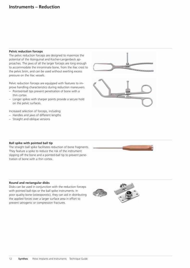
Pelvic reduction forcepsThe pelvic reduction forceps are designed to maximize thepotential of the ilioinguinal and Kocher-Langenbeck ap-proaches. The jaws of all the larger forceps are long enoughto accommodate the innominate bone, from the iliac crest tothe pelvic brim, and can be used without exerting excesspressure on the iliac vessels.
Pelvic reduction forceps are equipped with features to im-prove handling characteristics during reduction maneuvers.– Pointed-ball tips prevent penetration of bone with a
thin cortex.– Longer spikes with sharper points provide a secure hold
on the pelvic surfaces.
Increased selection of forceps, including– Handles and jaws of different lengths– Straight and oblique versions
Ball spike with pointed ball tipThe straight ball spike facilitates reduction of bone fragments.They feature a spike to reduce the risk of the instrument slipping off the bone and a pointed-ball tip to prevent pene-tration of bone with a thin cortex.
Round and rectangular disksDisks can be used in conjunction with the reduction forcepswith pointed ball-tips or the ball spike instruments. Inpoor quality bone (osteoporotic), they can aid in distributingthe applied forces over a larger surface area in effort to prevent iatrogenic or compression fractures.

Pelvic reduction forceps for screwsAll forceps have been designed for use with 3.5 mm/4.5 mmscrews inserted on opposite sides of a fracture line, which allows the application of considerable reduction forces andmanipulation in all three planes.
The large forceps have long handles for the transferal oflarge forces. The Faraboef forceps can be either used withscrews or as general bone forceps, i.e. to grasp and manipulate the iliac wing. – Jungbluth large (330 mm), small (250 mm, for 3.5 mm
screws)– Faraboef medium (250 mm), small (190 mm)
Reduction forceps with points These standard forceps can be applied directly to the bone’ssurface, or be used with shallow drill holes or anchoringrings and hooks.
Medium and large bone hooksThe bone hooks are designed to allow the surgeon to manip-ulate the bone or bone fragments in order to ensure properalignment and to achieve an anatomical reduction.
Pelvic Implants and Instruments Technique Guide Synthes 13

1
2
Plate Contouring
1Contour plate
Instruments
03.100.031 Bending Pliers for Reconstruction Plates 3.5
329.290 Bending Pliers for Reconstruction Plates 2.7 and 3.5
For plate contouring, place a plate between the ledge andthe groove of the bending pliers. Place the concave surfaceon the side of pliers with the ledge. Squeeze the handlesgradually and bend the plate as appropriate. (1)
For in-plane bending, place a plate into the groove of thebending pliers. Squeeze the handles gradually and bend theplate as appropriate. (2)
14 Synthes Pelvic Implants and Instruments Technique Guide

Pelvic Implants and Instruments Technique Guide Synthes 15
2Twist plate
Instruments
03.100.031 Bending Pliers for Reconstruction Plates 3.5
329.080 Bending Iron for Reconstruction Plates 3.5 and 4.5, length 190 mm
329.290 Bending Pliers for Reconstruction Plates 2.7 and 3.5
Hold the plate using the plier grips and twist the plate by using an additional bending iron.
Important: Avoid repeated bending and over bending as itweakens the plate. For reconstruction plates with coaxialcombi-holes: use threaded pin to avoid screw hole deforma-tion during bending.
Note: The bending pliers (03.100.031) are for use with3.5 mm reconstruction plates contained in the Low Profile3.5 mm Pelvic System. The bending pliers (329.290) arefor use with the standard 3.5 mm reconstruction plates.

16 Synthes Pelvic Implants and Instruments Technique Guide
In-situ Plate Contouring
In-situ bending instruments adjust the pre-bent, reconstruc-tion plates on the bone to match relevant patient anatomyduring a surgical procedure. Using this instruments helps decrease the surgical time by reducing the need for repeatedcycles of plate positioning and removal until the plate hasbeen sufficiently shaped.
IndicationsThe instruments are intended for use with the followingplate systems:– 3.5 mm Low Profile Reconstruction Plates (straight, curved
and J-shaped)– 3.5 mm Wide Angle Reconstruction Plates– 3.5 mm DCP Reconstruction Plates, straight and curved
ContraindicationsPlates with locking and coaxial combi-holes. In particular:– 3.5 mm Locking Reconstruction Plates– 3.5 mm Pubic Symphysis Plates– 3.5 mm Spring Plates– 3.5 mm Reconstruction Plates with coaxial combi-holes– Other plate sizes than 3.5 mm
Note: Preoperative pre-bending of the reconstruction platesis always required before in-situ plate bending. The in-situbending instruments are intended for detailed and accurateadaptation of the plates to the local anatomy.
Notes– Do not bend the plate at the level of the holes.– Do not bend the plate multiple times at the same level to
avoid weakening of the plate.

Pelvic Implants and Instruments Technique Guide Synthes 17
1 Contour plate: in-situ bending or correction of thebending radius
Instrument
03.100.090 In-situ Bender
Grasp the preliminary fixated plate with the in-situ bender.The nose and counter-bearing mouth of the bender must sitin the notches of the reconstruction plate.
Squeeze the handles and bend the plate as required.
2 Bend or twist plate
Instruments
03.100.091 In-situ Bending and Twisting Handle, straight
03.100.092 In-situ Bending and Twisting Handle, 90°
03.100.093 In-situ Bending and Twisting Handle, 120°
Use two straight in-situ bending and twisting handles.Place the tip of each handle in the plate hole. One handle isused for holding the plate while the second handle is mani-pulated to bend or twist the plate accordingly.
Note: The In-situ Bending and Twisting Handle, straight canbe combined with the In-situ Bending and Twisting Handle,90° or 120° where appropriate.
Note: Ensure that the tip of the instrument is properly at-tached to the plate to prevent slippage.

Fracture Fixation
Note: The following cases of fracture fixation represent possible uses of pelvic instruments. Several applications areshown but other applications are possible.
18 Synthes Pelvic Implants and Instruments Technique Guide
A. Pubic Symphysis Fractures
1Approach
Use an anterior approach (e.g. Pfannenstiel or Stoppa).

1
2
3
Pelvic Implants and Instruments Technique Guide Synthes 19
2Reduce fracture
Instruments
399.980 Reduction Forceps, large, with Points, ratchet lock, length 200 mm
398.750 Pelvic Reduction Forceps, for use with Cortex Screws � 3.5 and 4.5 mm
398.880 Pelvic Reduction Forceps, large, adjustable, speed lock, length 300 mm
Achieve reduction of the pubic symphysis by using the largereduction forceps with points. (1)
Alternatively, achieve reduction by inserting two screws ante-riorly and using pelvic reduction forceps (398.750/398.880).(2,3)

Fracture Fixation
20 Synthes Pelvic Implants and Instruments Technique Guide
3Fix plate
Instruments
03.100.032 Ratcheting Handle with AO/ASIF Quick Coupling
03.100.033 Screwdriver Shaft, hexagonal, for Screws � 3.5 mm, length 250 mm
324.214 Drill Bit � 2.8 mm, with Scale, length 200/100 mm, 3-flute, for Quick Coupling
311.310 Tap for Cortex Screws � 3.5 mm, calibrated, length 175 mm Pre-drilling: � 2.5 mm
312.648 LCP Drill Sleeve 3.5, for Drill Bits � 2.8 mm
314.090 Holding Sleeve, for Nos. 314.070, 314.550 and 314.570
314.570 Screwdriver, hexagonal, small, � 2.5 mm, length 270 mm for Screws � 3.5 mm
315.920 Drill Bit � 2.5 mm, calibrated, length 230/205 mm, 3-flute, for Quick Coupling
319.091 Depth Gauge for Cortex Screws � 3.5 mm, measuring range up to 150 mm
511.773 Torque Limiter, 1.5 Nm, for AO/ASIF Quick Coupling
Alternative instruments
03.100.045 Screwdriver Shaft Stardrive
314.115 Screwdriver Stardrive 3.5, T15

1 2
3
Pelvic Implants and Instruments Technique Guide Synthes 21
Place the 3.5 mm symphysis plate over the symphysis jointand make a temporary fixation (e.g. with plate holding for-ceps).
According to preoperative planning and plate selection (locking /non-locking), use � 3.5 mm cortex screws and/or� 3.5 mm locking screws to fix the plate. If compressionis needed between the symphysis joint, use the plate withDCU holes.
Insert the first cortex screw in the lateral part of DCU hole(eccentric). Insert the second cortex screw eccentrically intothe DCU hole of the contralateral side of the pubic symphysis.(1,2)
Alternate tensioning of the screws results in compression ofthe symphysis.
Refer to the DCP technique guide (036.001.093) for moredetailed steps during screw insertion and plate fixation.
Additional locking screws should be inserted according tothe LCP technique guide 036.000.019. (3)
Notes– The x-ray template 034.000.485 indicates locking screw
directions.– Refer to the DCP (036.001.093) and/or LCP (036.000.019)
technique guides for independent lag screw placementand plating.
– Screwdriver Shaft Stardrive (03.100.045) and Screwdriver Stardrive 3.5, T15 (314.115) are used for � 3.5 mm Stardrive screws.

Fracture Fixation
22 Synthes Pelvic Implants and Instruments Technique Guide
B. Iliac Fractures
2Reduce fracture
Instruments
398.740 Pelvic Reduction Forceps, small, length 190 mm, for use with Cortex Screws � 3.5 and 4.5 mm
399.980 Reduction Forceps with Points, ratchet lock, length 180 mm
Confirm anatomical reduction of the anterior aspect of theiliac wing by finger palpation.
To reduce the iliac bone, use reduction forceps on the iliaccrest and the posterior iliac wing.
1Approach
Use an anterior or posterior approach appropriate for thefracture pattern. The following example of an iliac fractureshows a possible fracture treatment using a posterior(Kocher – Langenbeck) approach.

1
2
Alternative technique
Instruments
311.310 Tap for Cortex Screws � 3.5 mm, calibrated, length 175 mm Pre-drilling: � 2.5 mm
314.570 Screwdriver, hexagonal, small, � 2.5 mm, length 270 mm for Screws � 3.5 mm
315.920 Drill Bit � 2.5 mm, calibrated, length 230/205 mm, 3-flute, for Quick Coupling
319.091 Depth Gauge for Cortex Screws � 3.5 mm, measuring range up to 150 mm
398.750 Pelvic Reduction Forceps, medium, length 250 mm, for use with Cortex Screws � 3.5 and 4.5 mm
398.880 Pelvic Reduction Forceps, large, adjustable, speed lock, length 300 mm
399.980 Reduction Forceps with Points, ratchet lock, length 180 mm
Alternatively, insert two temporary cortex screws on either side of the fracture line and gain compression using pelvic reduction forceps: 398.750 Faraboef (1) or 398.880, Jungbluth (2).
Pelvic Implants and Instruments Technique Guide Synthes 23

Fracture Fixation
24 Synthes Pelvic Implants and Instruments Technique Guide
3Fix plate on posterior inferior ilium
Instruments
03.100.032 Ratcheting Handle with AO/ASIF Quick Coupling
03.100.033 Screwdriver Shaft, hexagonal, for Screws � 3.5 mm, length 250 mm
311.310 Tap for Cortex Screws � 3.5 mm, calibrated, length 175 mm Pre-drilling: � 2.5 mm
314.090 Holding Sleeve, for Nos. 314.070, 314.550 and 314.570
314.570 Screwdriver, hexagonal, small, � 2.5 mm, length 270 mm for Screws � 3.5 mm
315.920 Drill Bit � 2.5 mm, calibrated, length 230/205 mm, 3-flute, for Quick Coupling
319.091 Depth Gauge for Cortex Screws � 3.5 mm, measuring range up to 150 mm
399.091 Bone Holding Forceps, self-centering, soft lock, length 191 mm
399.980 Reduction Forceps, large, with Points, ratchet lock, length 200 mm
Alternative instruments
03.100.045 Screwdriver Shaft Stardrive
314.115 Screwdriver Stardrive 3.5, T15

1 2
3 4
Pelvic Implants and Instruments Technique Guide Synthes 25
Insert a screw through the 4-hole low profile pelvic recon-struction plate into the body of the ilium, close to the sciaticnotch. (1)
To reduce the posterior iliac fragment, insert a temporaryscrew into the posterior superior iliac spine. (2) Compress the fracture using the bone holding forceps. The forcepsis therefore hooked into the most posterior plate hole andthe temporary screw on the other side of the fracture lineis used as a counter bearing. (3)
After additional screw fixation through the plate, removethe temporary screw. (4)
Notes – During fixation close to the greater sciatic notch, control
drill bit penetration and screw lengths with two-fingerpalpation to prevent damage to the nerve or vessels.
– Refer to the DCP (036.001.093) and/or LCP (036.000.019)technique guide for independent lag screw placement andplating.

4Fix plate on iliac crest
Instruments
03.100.018 Ball Spike, straight, with pointed ball tips � 6.5 mm, length 300 mm
03.100.032 Ratcheting Handle with AO/ASIF Quick Coupling
03.100.033 Screwdriver Shaft, hexagonal, for Screws � 3.5 mm, length 250 mm
311.310 Tap for Cortex Screws � 3.5 mm, calibrated, length 175 mm Pre-drilling: � 2.5 mm
314.090 Holding Sleeve, for Nos. 314.070, 314.550 and 314.570
314.570 Screwdriver, hexagonal, small, � 2.5 mm, length 270 mm for Screws � 3.5 mm
315.920 Drill Bit � 2.5 mm, calibrated, length 230/205 mm, 3-flute, for Quick Coupling
319.091 Depth Gauge for Cortex Screws � 3.5 mm, measuring range up to 150 mm
399.980 Reduction Forceps, large, with Points, ratchet lock, length 200 mm
Alternative instruments
03.100.045 Screwdriver Shaft Stardrive
314.115 Screwdriver Stardrive 3.5, T15
Fracture Fixation
26 Synthes Pelvic Implants and Instruments Technique Guide
Pelvic Implants and Instruments Technique Guide Synthes 27
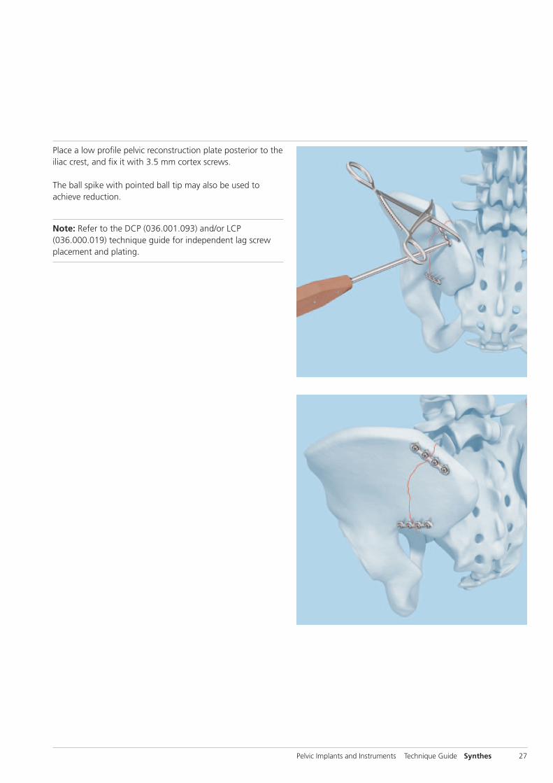
Place a low profile pelvic reconstruction plate posterior to theiliac crest, and fix it with 3.5 mm cortex screws.
The ball spike with pointed ball tip may also be used toachieve reduction.
Note: Refer to the DCP (036.001.093) and/or LCP(036.000.019) technique guide for independent lag screwplacement and plating.

C. Acetabulum Two Column Fractures
Fracture Fixation
28 Synthes Pelvic Implants and Instruments Technique Guide
1Approach
Use an ilioinguinal approach.

1
2
3
2Reduce fracture in iliac crest
Instruments
03.100.019 Ball Spike, straight, long, with pointed ball tips � 6.5 mm, length 400 mm
294.680 Schanz Screw � 6.0 mm, length 190/50 mm, Stainless Steel
398.740 Pelvic Reduction Forceps, small, length 190 mm, for use with Cortex Screws � 3.5 and 4.5 mm
399.980 Reduction Forceps, large, with Points, ratchet lock, length 200 mm
Insert a Schanz screw into the proximal femur to allow intraoperative manual traction. (1)
Confirm anatomic reconstruction of the different fracturefragments. Fragments may be temporarily fixated withKirschner wires. (2)
Different reduction instruments (e.g. ball spike, reduction forceps) may aid in achieving appropriate reduction. (2,3)
Pelvic Implants and Instruments Technique Guide Synthes 29

Fracture Fixation
30 Synthes Pelvic Implants and Instruments Technique Guide
3Insert screw in iliac crest
Instruments
03.100.032 Ratcheting Handle with AO/ASIF Quick Coupling
03.100.033 Screwdriver Shaft, hexagonal, for Screws � 3.5 mm, length 250 mm
310.370 Drill Bit � 3.5 mm, length 195/170 mm, 2-flute, for Quick Coupling
311.310 Tap for Cortex Screws � 3.5 mm, calibrated, length 175 mm Pre-drilling: � 2.5 mm
314.090 Holding Sleeve, for Nos. 314.070, 314.550 and 314.570
314.570 Screwdriver, hexagonal, small, � 2.5 mm, length 270 mm for Screws � 3.5 mm
315.920 Drill Bit � 2.5 mm, calibrated, length 230/205 mm, 3-flute, for Quick Coupling
319.091 Depth Gauge for Cortex Screws � 3.5 mm, measuring range up to 150 mm
398.740 Pelvic Reduction Forceps, small, length 190 mm, for use with Cortex Screws � 3.5 and 4.5 mm
399.980 Reduction Forceps, large, with Points, ratchet lock, length 200 mm
Alternative instruments
03.100.045 Screwdriver Shaft Stardrive
314.115 Screwdriver Stardrive 3.5, T15
4Insert screw in body of ilium
Instrument
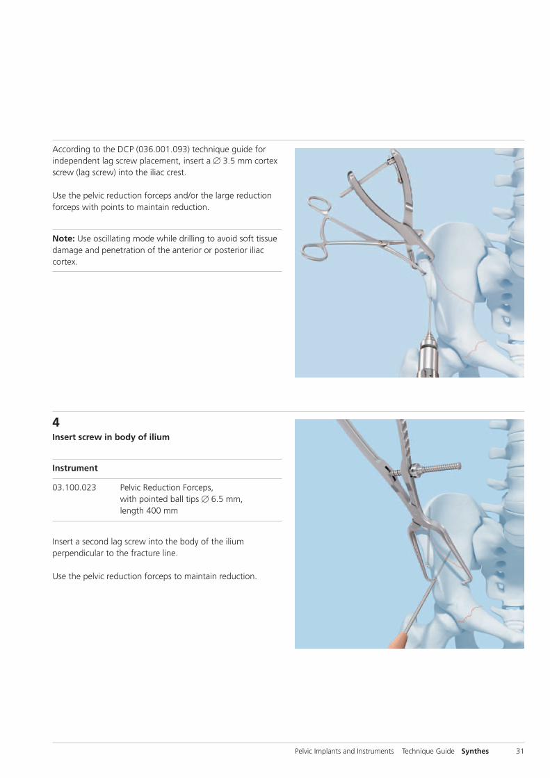
03.100.023 Pelvic Reduction Forceps, with pointed ball tips � 6.5 mm, length 400 mm
Insert a second lag screw into the body of the ilium perpendicular to the fracture line.
Use the pelvic reduction forceps to maintain reduction.
Pelvic Implants and Instruments Technique Guide Synthes 31
According to the DCP (036.001.093) technique guide for independent lag screw placement, insert a � 3.5 mm cortexscrew (lag screw) into the iliac crest.
Use the pelvic reduction forceps and/or the large reductionforceps with points to maintain reduction.
Note: Use oscillating mode while drilling to avoid soft tissuedamage and penetration of the anterior or posterior iliac cortex.

1
Fracture Fixation
32 Synthes Pelvic Implants and Instruments Technique Guide
Alternative technique
Instruments
03.100.020 Pelvic Reduction Forceps, with pointed ball tips � 6.5 mm, length 250 mm
03.100.022 Pelvic Reduction Forceps, angled, with pointed ball tips � 6.5 mm, length 240 mm
03.100.029 Bone Hook, medium, long, length 330 mm
03.100.120 Spiked Disc, round, hole 6.5 mm
314.291 Collinear Reduction Clamp (Sliding Mechanism)
398.753 Pelvic Arm, for Collinear Reduction Clamp
Alternatively the pelvic reduction forceps with pointed balltips (straight or angled) can be used to reduce the fracture.If necessary, spiked discs can be used with all pelvic reductionforceps with ball tips. (1)
5Reduce posterior column
Instrument
399.980 Reduction Forceps, large, with Points, ratchet lock, length 200 mm
Use the reduction forceps with points to reduce the frag-ment of the quadrilateral surface. The clamp bridges fromthe pelvic brim to the quadrilateral surface.

2
3
Pelvic Implants and Instruments Technique Guide Synthes 33
The collinear reduction clamp with pelvic arm is useful to reduce the posterior column. (2)
The bone hook placed beneath the ischial spine may also beused to reduce the posterior column. (3)

34 Synthes Pelvic Implants and Instruments Technique Guide
Fracture Fixation
6In-situ plate contouring
If preoperative bending is insufficient after plate positioning,insertion and tightening of the first screws, the in-situ bend-ing instruments can be used to further adapt the plate to thelocal anatomy.
Instruments
03.100.090 In-situ Bender
03.100.091 In-situ Bending and Twisting Handle, straight
03.100.092 In-situ Bending and Twisting Handle, 90°
03.100.093 In-situ Bending and Twisting Handle, 120°
If in-situ plate adaptation is required, use the in-situ benderas described on page 16.

Pelvic Implants and Instruments Technique Guide Synthes 35
If plate needs to be bent or twisted to fit the local anatomy,the in-situ bending and twisting handles should be used asdescribed on page 17.
36 Synthes Pelvic Implants and Instruments Technique Guide
7Fix plate on pelvic brim
Instruments
03.100.019 Ball Spike, straight, long, with pointed ball tips � 6.5 mm, length 400 mm
03.100.032 Ratcheting Handle with AO/ASIF Quick Coupling
03.100.033 Screwdriver Shaft, hexagonal, for Screws � 3.5 mm, length 250 mm
311.310 Tap for Cortex Screws � 3.5 mm, calibrated, length 175 mm Pre-drilling: � 2.5 mm
314.090 Holding Sleeve, for Nos. 314.070, 314.550 and 314.570
314.291 Collinear Reduction Clamp (Sliding Mechanism)
314.570 Screwdriver, hexagonal, small, � 2.5 mm, length 270 mm for Screws � 3.5 mm
315.920 Drill Bit � 2.5 mm, calibrated, length 230/205 mm, 3-flute, for Quick Coupling
319.091 Depth Gauge for Cortex Screws � 3.5 mm, measuring range up to 150 mm
398.753 Pelvic Arm, for Collinear Reduction Clamp
Alternative instruments
03.100.045 Screwdriver Shaft Stardrive
314.115 Screwdriver Stardrive 3.5, T15
Fracture Fixation

Pelvic Implants and Instruments Technique Guide Synthes 37
8Fix plate on pubic rami
Insert additional screws through the plate into the pubicrami to maintain reduction and stable fixation of the anteriorcolumn.
Note: Refer to the DCP (036.001.093) and/or LCP (036.000.019) technique guide for lag screw placementand plating.
Fix a J-plate with � 3.5 mm cortex screws on the pelvic brimaccording to the DCP (036.001.093) technique guide.Lag screws through the plate help to achieve a stable fixationbetween the anterior and posterior column.
38 Synthes Pelvic Implants and Instruments Technique Guide
Plates
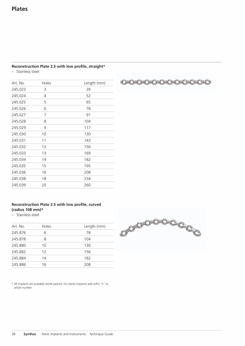
Reconstruction Plate 3.5 with low profile, straight*– Stainless steel
Art. No. Holes Length (mm)
245.023 3 39
245.024 4 52
245.025 5 65
245.026 6 78
245.027 7 91
245.028 8 104
245.029 9 117
245.030 10 130
245.031 11 143
245.032 12 156
245.033 13 169
245.034 14 182
245.035 15 195
245.036 16 208
245.038 18 234
245.039 20 260
Reconstruction Plate 3.5 with low profile, curved(radius 108 mm)*– Stainless steel
Art. No. Holes Length (mm)
245.876 6 78
245.878 8 104
245.880 10 130
245.882 12 156
245.884 14 182
245.886 16 208
* All implants are available sterile packed. For sterile implants add suffix “S” toarticle number.
Pelvic Implants and Instruments Technique Guide Synthes 39
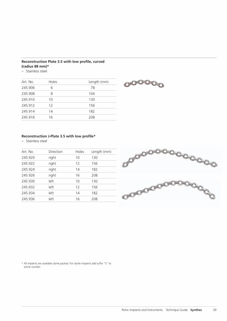
Reconstruction Plate 3.5 with low profile, curved(radius 88 mm)* – Stainless steel
Art. No. Holes Length (mm)
245.906 6 78
245.908 8 104
245.910 10 130
245.912 12 156
245.914 14 182
245.916 16 208
Reconstruction J-Plate 3.5 with low profile*– Stainless steel
Art. No. Direction Holes Length (mm)
245.920 right 10 130
245.922 right 12 156
245.924 right 14 182
245.926 right 16 208
245.930 left 10 130
245.932 left 12 156
245.934 left 14 182
245.936 left 16 208
* All implants are available sterile packed. For sterile implants add suffix “S” toarticle number.

40 Synthes Pelvic Implants and Instruments Technique Guide
Symphyseal Plate 3.5 with coaxial combi-holes*– Stainless steel
Art. No. Holes Length (mm)
02.100.004 4 57
02.100.006 6 78
Symphyseal Plate 3.5 with coaxial combi-holes* and 2 DCP– Stainless steel
Art. No. Holes Length (mm)
02.100.014 4 57
02.100.016 6 78
Reconstruction J-Plate 3.5 with coaxial combi-holes,(radius 88 mm)*– Stainless steel
Art. No. Direction Holes Length (mm)
02.100.360 right 10 130
02.100.362 right 12 156
02.100.364 right 14 182
02.100.366 right 16 208
02.100.361 left 10 130
02.100.363 left 12 156
02.100.365 left 14 182
02.100.367 left 16 208
Plates
* All implants are available sterile packed. For sterile implants add suffix “S” toarticle number.

Pelvic Implants and Instruments Technique Guide Synthes 41
Reconstruction Plate 3.5 with coaxial combi-holes,straight*– Stainless steel
Art. No. Holes Length (mm)
02.100.103 3 39
02.100.104 4 52
02.100.105 5 65
02.100.106 6 78
02.100.107 7 91
02.100.108 8 104
02.100.109 9 117
02.100.110 10 130
02.100.111 11 143
02.100.112 12 156
02.100.113 13 169
02.100.114 14 182
02.100.115 15 195
02.100.116 16 208
02.100.118 18 234
02.100.120 20 260
* All implants are available sterile packed. For sterile implants add suffix “S” toarticle number.

42 Synthes Pelvic Implants and Instruments Technique Guide
Reconstruction Plate 3.5 with wide Angle, straight* – Stainless steel
Art. No. Holes Length (mm)
02.100.203 3 39
02.100.204 4 52
02.100.205 5 65
02.100.206 6 78
02.100.207 7 91
02.100.208 8 104
02.100.209 9 117
02.100.210 10 130
02.100.211 11 143
02.100.212 12 156
02.100.213 13 169
02.100.214 14 182
02.100.215 15 195
02.100.216 16 208
02.100.218 18 234
02.100.220 20 260
Spring Plate 3.5*– Stainless steel
Art. No. Holes Length (mm)
02.100.301 1 19.5
02.100.302 2 31.5
02.100.303 3 43.5
Plates
* All implants are available sterile packed. For sterile implants add suffix “S” toarticle number.

Pelvic Implants and Instruments Technique Guide Synthes 43
Screws
02.200.010–150 Cortex Screw Stardrive � 3.5 mm, self-tapping, length 10 – 150 mm,*
Stainless Steel
204.630–750 Pelvic Cortex Screw � 3.5 mm,self-tapping, head height 2.75 mm,length 30– 150 mm,* Stainless Steel
204.810–838 Cortex Screw � 3.5 mm, selftapping,length 10– 38 mm,* Stainless Steel
213.010–095 Locking Screw � 3.5 mm, selftapping, length 10– 95 mm,* Stainless Steel
02.200.003 Threaded Pin Stardrive � 3.5 mm,* Stainless Steel
Locking Screw Stardrive � 3.5 mm, self-tapping*– Stainless steel
Art. No. Length (mm)
212.101 10
212.102 12
212.103 14
212.104 16
212.105 18
212.106 20
212.107 22
212.108 24
212.109 26
212.110 28
212.111 30
212.112 32
212.113 34
212.115 36
Art. No. Length (mm)
212.116 38
212.117 40
212.119 45
212.121 50
212.123 55
212.124 60
212.125 65
212.126 70
212.127 75
212.128 80
212.129 85
212.130 90
212.131 95
* All implants are available sterile packed. For sterile implants add suffix “S” toarticle number.

44 Synthes Pelvic Implants and Instruments Technique Guide
Instruments
03.100.011 Pelvic Retractor, medium, length 268 mm
03.100.012 Pelvic Retractor, large, length 323 mm
03.100.013 Retractor for Sciatic Nerve
03.100.014 Retractor for Sciatic Nerve, long
03.100.015 Retractor, malleable, width 20 mm,length 330 mm
03.100.016 Retractor, malleable, width 30 mm,length 330 mm
03.100.017 Retractor, malleable, width 40 mm,length 330 mm

Pelvic Implants and Instruments Technique Guide Synthes 45
03.100.107 Radioluscent Pelvic Retractor, blunt,length 274 mm, Aluminium
03.100.108 Radioluscent Hohmann Retractor, width35 mm, length 275 mm, Aluminium
03.100.109 Radioluscent Hohmann Retractor, width18 mm, length 240 mm, Aluminium
03.100.110 Radioluscent Hohmann Retractor, width24 mm, length 267 mm, Aluminium
03.100.111 Radioluscent Pelvic Retractor, medium,length 268 mm, Aluminium
03.100.112 Radioluscent Pelvic Retractor, large,length 323 mm, Aluminium
398.550 Pelvic Retractor, blunt
399.270 Bone Lever, long narrow tip, width 18 mm,length 235 mm
03.100.018 Ball Spike, straight, with pointed ball tips� 6.5 mm, length 300 mm
03.100.019 Ball Spike, straight, long, with pointed balltips � 6.5 mm, length 400 mm

46 Synthes Pelvic Implants and Instruments Technique Guide
03.100.021 Pelvic Reduction Forceps, angled,with pointed ball tips � 6.5 mm,length 200 mm
03.100.022 Pelvic Reduction Forceps, angled,with pointed ball tips � 6.5 mm,length 240 mm
03.100.024 Pelvic Reduction Forceps, asymmetric,with pointed ball tips � 6.5 mm
03.100.027 Disc, round, hole � 6.5 mm
03.100.028 Disc, rectangular, hole � 6.5 mm
03.100.120 Spiked Disc, round, hole 6.5 mm
03.100.121 Spiked Disc, rectangular, hole � 6.5 mm
398.740 Pelvic Reduction Forceps, small,length 190 mm, for use with Cortex Screws � 3.5 and 4.5 mm
03.100.020 Pelvic Reduction Forceps with pointed balltips � 6.5 mm, length 250 mm
03.100.023 Pelvic Reduction Forceps with pointed balltips � 6.5 mm, length 400 mm
Instruments

Pelvic Implants and Instruments Technique Guide Synthes 47
398.750 Pelvic Reduction Forceps, medium,length 250 mm, for use with Cortex Screws � 3.5 and 4.5 mm
398.880 Pelvic Reduction Forceps, large, adjustable,speed lock, length 300 mm
03.100.025 Pelvic Reduction Forceps, small, for Screws � 3.5 mm, length 250 mm
399.980 Reduction Forceps, large, with Points,ratchet lock, length 200 mm
03.100.029 Bone Hook, medium, long, length 330 mm
03.100.030 Bone Hook, large, long, length 330 mm
398.520 Bone Hook, sharp, medium, length 230 mm
398.530 Bone Hook, sharp, large, length 200 mm
03.100.031 Bending Pliers for Reconstruction Plates 3.5
329.080 Bending Iron for Reconstruction Plates3.5 and 4.5, length 190 mm

48 Synthes Pelvic Implants and Instruments Technique Guide
03.100.034 Bending Template for Low Profile 3.5Reconstruction Plates, straight, 20 holes
03.100.035 Bending Template for Low Profile 3.5Reconstruction J-Plates, 16 holes
03.100.036 Bending Template for Low Profile 3.5Reconstruction Plates, curved (R88), 16 holes
03.100.037 Bending Template for Low Profile 3.5Reconstruction Plates, curved (R108), 16 holes
Instruments
03.100.090 In-situ Bender
03.100.091 In-situ Bending and Twisting Handle,straight
03.100.092 In-situ Bending and Twisting Handle, 90°
03.100.093 In-situ Bending and Twisting Handle, 120°

Pelvic Implants and Instruments Technique Guide Synthes 49
324.031 Plate Holder with thread � 3.5 mm, long
03.100.040 LCP Drill Sleeve 3.5, short, with thread,for Drill Bits � 2.8 mm
312.648 LCP Drill Sleeve 3.5, for Drill Bits � 2.8 mm
315.920 Drill Bit � 2.5 mm, calibrated,length 230/205 mm, 3-flute, forQuick Coupling
324.210 Drill Bit � 2.5 mm, calibrated, length 300 mm, with Quick Coupling, for Percutaneous Insertion
324.214 Drill Bit � 2.8 mm, with Scale,length 200/100 mm, 3-flute, forQuick Coupling
310.288 Drill Bit � 2.8 mm, length 165 mm, for AO/ASIF Quick Coupling
310.370 Drill Bit � 3.5 mm, length 195/170 mm,2-flute, for Quick Coupling
319.091 Depth Gauge for Cortex Screws� 3.5 mm, measuring range upto 150 mm
311.310 Tap for Cortex Screws � 3.5 mm,calibrated, length 175 mm
311.431 Handle with Quick Coupling

50 Synthes Pelvic Implants and Instruments Technique Guide
314.115 Screwdriver Stardrive 3.5, T15
314.116 Screwdriver Shaft Stardrive 3.5, T15,self-holding, for AO/ASIF Quick Coupling
03.100.045 Screwdriver Shaft Stardrive 3.5, T15,length 250 mm, for AO/ASIF Quick Coupling
511.773 Torque Limiter, 1.5 Nm, for AO/ASIF Quick Coupling
393.100 Universal Chuck with T-Handle
398.650 Pliers for Screw Removal, length 205 mm
Instruments
03.100.032 Ratcheting Handle with AO/ASIF Quick Coupling
319.970 Screw Forceps, self-holding, length 85 mm
314.090 Holding Sleeve, for Nos. 314.070, 314.550and 314.570
314.570 Screwdriver, hexagonal, small, � 2.5 mm,length 270 mm
03.100.033 Screwdriver Shaft, hexagonal, for Screws � 3.5 mm, length 250 mm

Pelvic Implants and Instruments Technique Guide Synthes 51
Optional Implants
DCP 4.5, narrow*– Stainless steel
Art. No. Holes Length (mm)
224.020 2 39
224.040 4 71
LC-DCP 4.5, narrow*– Stainless steel
Art. No. Holes Length (mm)
224.520 2 34
224.530 3 52
224.540 4 70
Reconstruction Plate 4.5, straight*X = 2: Stainless steelX = 4: Titanium
Art. No. Holes Length (mm)
X29.330 3 45
X29.340 4 61
X29.350 5 77
X29.360 6 93
X29.370 7 109
X29.380 8 125
X29.390 9 141
Art. No. Holes Length (mm)
X29.400 10 157
X29.410 11 173
X29.420 12 189
X29.430 13 205
X29.440 14 221
X29.450 15 237
X29.460 16 253
* All implants are available sterile packed. For sterile implants add suffix “S” toarticle number.

52 Synthes Pelvic Implants and Instruments Technique Guide
Reconstruction Plate 3.5, straight*X=2: Stainless steelX=4: Titanium
Art. No. Holes Length (mm)
X45.150 5 58
X45.160 6 70
X45.170 7 82
X45.180 8 94
X45.190 9 106
X45.000 10 118
X45.020 12 142
X45.040 14 166
X45.060 16 190
X45.080 18 214
X45.100 20 238
X45.120 22 262
Pelvic Reconstruction Plate 3.5, curved*X=2: Stainless steelX=4: Titanium
Art. No. Holes Length (mm)
X45.300 6 70
X45.310 8 94
X45.320 10 118
X45.330 12 142
X45.340 14 166
X45.350 16 190
X45.360 18 214
* All implants are available sterile packed. For sterile implants add suffix “S” toarticle number.
Optional Implants

Pelvic Implants and Instruments Technique Guide Synthes 53
Optional Screws
Cortex Screws*X=2: Stainless steelX=4: Titanium
X04.810 – 930 Cortex Screw � 3.5 mm, self-tapping,length 10– 130 mm
X14.814 – 940 Cortex Screw � 4.5 mm, self-tapping, length 14– 140 mm
Cancellous Bone Screws*X=2: Stainless steelX=4: Titanium
X06.010 – 060 Cancellous Bone Screw � 4.0 mm, fully threaded, length 10– 60 mm
X07.010 – 060 Cancellous Bone Screw � 4.0 mm, short thread, length 10– 60 mm
X16.030 – 120 Cancellous Bone Screw � 6.5 mm, thread length 16 mm, length 30– 120 mm
X17.045 – 150 Cancellous Bone Screw � 6.5 mm, thread length 32 mm, length 45– 150 mm
X18.020 – 110 Cancellous Bone Screw � 6.5 mm, fully threaded, length 20– 110 mm
294.680* Schanz Screw � 6.0 mm, length 190/50 mm, Stainless Steel
X19.980* Washer � 7.0/3.6 mm, for Screws � 2.7 to 4.0 mm
* All implants are available sterile packed. For sterile implants add suffix “S” toarticle number.
54 Synthes Pelvic Implants and Instruments Technique Guide
Optional Instruments
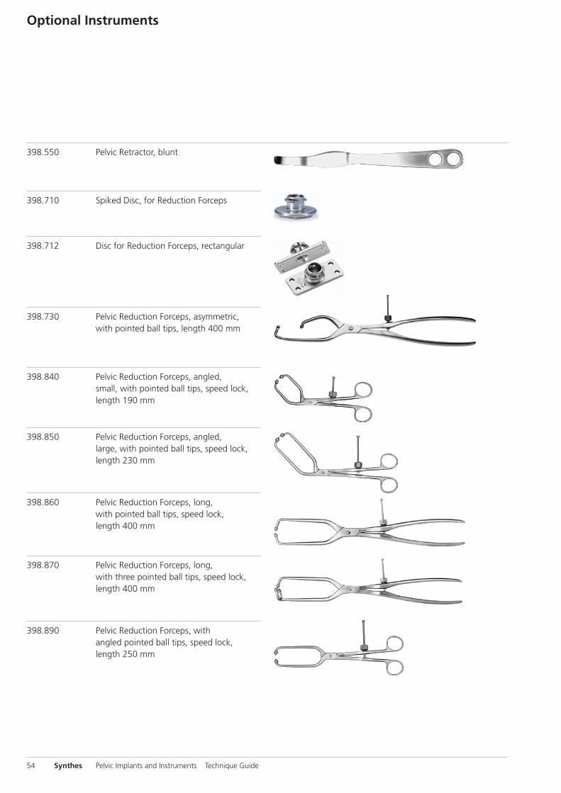
398.550 Pelvic Retractor, blunt
398.710 Spiked Disc, for Reduction Forceps
398.712 Disc for Reduction Forceps, rectangular
398.730 Pelvic Reduction Forceps, asymmetric,with pointed ball tips, length 400 mm
398.840 Pelvic Reduction Forceps, angled,small, with pointed ball tips, speed lock,length 190 mm
398.850 Pelvic Reduction Forceps, angled,large, with pointed ball tips, speed lock,length 230 mm
398.860 Pelvic Reduction Forceps, long,with pointed ball tips, speed lock,length 400 mm
398.870 Pelvic Reduction Forceps, long,with three pointed ball tips, speed lock,length 400 mm
398.890 Pelvic Reduction Forceps, with angled pointed ball tips, speed lock,length 250 mm

398.540 Ball Spike, with pointed ball tip,length 300 mm
399.092 Reduction Forceps, large, with Points, soft lock, length 222 mm
399.850 Pelvic Osteotomy Chisel, width 15 mm,length 304/134 mm
399.860 Pelvic Osteotomy Chisel, width 20 mm,length 304/134 mm
329.290 Bending Pliers for Reconstruction Plates2.7 and 3.5
329.640 Bending Template for StraightReconstruction Plates 3.5
329.660 Bending Template for CurvedReconstruction Plates 3.5
329.680 Bending Template for StraightReconstruction Plates 4.5, to be cut
391.968 Shortcut 2.7 to 4.5, without rasp, for Reconstruction Plates 2.7 to 4.5,required in pairs
391.969 Shortcut 2.7 to 4.5, with Rasp, for Reconstruction Plates 2.7 to 4.5, required in pairs
Pelvic Implants and Instruments Technique Guide Synthes 55
Optional Instruments
56 Synthes Pelvic Implants and Instruments Technique Guide
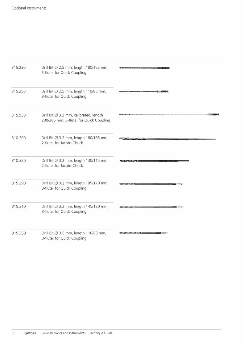
315.230 Drill Bit � 2.5 mm, length 180/155 mm, 3-flute, for Quick Coupling
315.250 Drill Bit � 2.5 mm, length 110/85 mm,3-flute, for Quick Coupling
315.930 Drill Bit � 3.2 mm, calibrated, length230/205 mm, 3-flute, for Quick Coupling
310.300 Drill Bit � 3.2 mm, length 180/165 mm,2-flute, for Jacobs Chuck
310.320 Drill Bit � 3.2 mm, length 130/115 mm,2-flute, for Jacobs Chuck
315.290 Drill Bit � 3.2 mm, length 195/170 mm,3-flute, for Quick Coupling
315.310 Drill Bit � 3.2 mm, length 145/120 mm,3-flute, for Quick Coupling
315.350 Drill Bit � 3.5 mm, length 110/85 mm,3-flute, for Quick Coupling

310.450 Drill Bit � 4.5 mm, length 130/115 mm,2-flute, for Jacobs Chuck
310.480 Drill Bit � 4.5 mm, length 195/170 mm,2-flute, for Quick Coupling
310.490 Drill Bit � 4.5 mm, length 180/165 mm,2-flute, for Jacobs Chuck
315.440 Drill Bit � 4.5 mm, length 145/120 mm,3-flute, for Quick Coupling
315.480 Drill Bit � 4.5 mm, length 195/170 mm,3-flute, for Quick Coupling
319.090 Depth Gauge for Long Screws � 3.5 mm,measuring range up to 110 mm
311.320 Tap for Cortex Screws � 3.5 mm, length 110/50 mm
311.330 Tap for Cortex Screws � 3.5 mm, length 180/110 mm
Pelvic Implants and Instruments Technique Guide Synthes 57
58 Synthes Pelvic Implants and Instruments Technique Guide
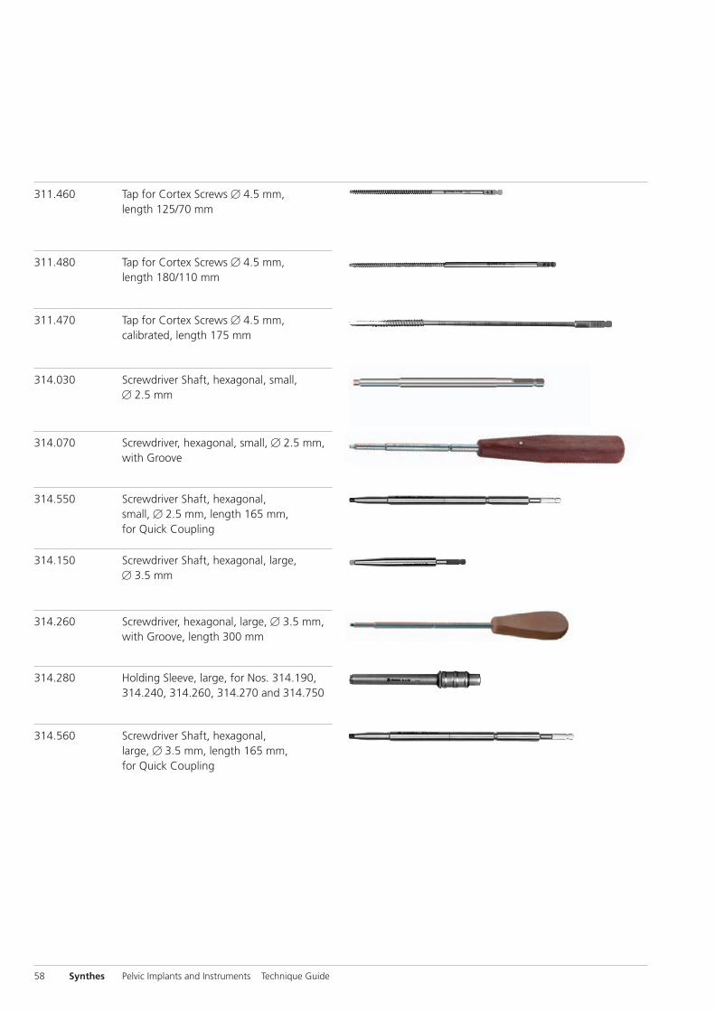
311.460 Tap for Cortex Screws � 4.5 mm, length 125/70 mm
311.480 Tap for Cortex Screws � 4.5 mm, length 180/110 mm
311.470 Tap for Cortex Screws � 4.5 mm,calibrated, length 175 mm
314.030 Screwdriver Shaft, hexagonal, small, � 2.5 mm
314.070 Screwdriver, hexagonal, small, � 2.5 mm,with Groove
314.550 Screwdriver Shaft, hexagonal, small, � 2.5 mm, length 165 mm, for Quick Coupling
314.150 Screwdriver Shaft, hexagonal, large, � 3.5 mm
314.260 Screwdriver, hexagonal, large, � 3.5 mm,with Groove, length 300 mm
314.280 Holding Sleeve, large, for Nos. 314.190,314.240, 314.260, 314.270 and 314.750
314.560 Screwdriver Shaft, hexagonal, large, � 3.5 mm, length 165 mm,for Quick Coupling

Other Available Pelvic Instrumentsand Implants from Synthes
Collinear Reduction Clamp SetThe Collinear Reduction Clamp assists in achieving and main-taining fracture reduction in minimally invasive techniques.The system consists of sliding mechanism, attachable armsand reduction attachments according to the clinical needs.Refer to technique guide: 036.000.253.
Cannulated Percutaneous Guiding System SetThe Cannulated Percutaneous Guiding System is a soft tissueprotector to assist in pelvic and acetabular reconstructive surgery. It allows for less invasive placement of 3.5 mm cor-tex or pelvic screws as well as 4.0 cancellous screws. It accepts temporary fixation with Kirschner wires/guide wiresup to � 2.8 mm. Refer to technique guide: 036.000.750.
Pelvic Implants and Instruments Technique Guide Synthes 59

Other Available Pelvic Instruments and Implants from Synthes
60 Synthes Pelvic Implants and Instruments Technique Guide
Pelvic C-ClampThe Pelvic C-Clamp is an emergency stabilization instrumentfor unstable injuries and fractures of the pelvic ring. Unstablepelvic ring fractures can be associated with massive lossof blood that can cause terminal shock. The Pelvic C-Clampallows rapid reduction and stabilization of these unstablepelvic ring fractures, thus assisting the surgeon to gain con-trol of the shock reaction. This neither delays nor hinderssubsequent diagnosis and therapy.
Note: The Pelvic C-Clamp is not contained in the pelvic sets.See separate Synthes publication “Pelvic C-Clamp”. Refer totechnique guide: 036.000.899.
Large External FixatorIndications for stabilizing the anterior pelvic ring with alarge external fixator are: Unstable fractures in the anteriorpelvic ring, or symphysis fractures with or without participa-tion of the posterior pelvic ring. This type of stabilizationis also possible in emergencies such as polytrauma, openwounds and, where appropriate, as an alternative to internalosteosynthesis.
The pelvis can be stabilized with an external fixator both atthe iliac crest and the supraacetabular region.
The clamps are magnetic resonance conditional. This allows magnetic resonance examinations of patients who have beenstabilized with the external fixator.Refer to technique guide: 036.000.237.

Spring Plate 3.5The Synthes Spring Plate 3.5 is intended for reduction andfixation of small bone fragments.
In pelvic and acetabular surgery, it is often difficult to reduceand fix small bone fragments with screws because the fragments may break into even smaller pieces. Mainly in thejoint areas (acetabulum) it is essential that even small frag-ments are anatomically reduced and help to achieve again ahomogenous joint congruency. The 3.5 Spring Plates are in-tended to reduce and stabilize bone fragments that aretoo small for screws. They can be used individually or in con-junction with a 3.5 mm reconstruction plate. Refer to technique guide: 036.000.581.
Sacral BarsThe Synthes 6.0 mm Threaded Sacral Bars offer an additionaloption for stabilization of the posterior pelvic ring.
Two threaded bars are therefore drilled through the posterioriliac crests and by compression of the nuts, bridging andcompression of the posterior pelvic ring is achieved.
Note: Two 6.0 mm Threaded Sacral Bar Kits are necessaryto build the construct described in the technique guide. Also,bolt cutters capable of cutting a 6.0 mm bar will be neces-sary to complete the procedure (Rod Cutter 388.720 is avail-able). Refer to technique guide: 036.000.740.
Pelvic Implants and Instruments Technique Guide Synthes 61

Other Available Pelvic Instruments and Implants from Synthes
62 Synthes Pelvic Implants and Instruments Technique Guide
Trocar for Cannulated Screws 6.5 and 7.3 mmThe trocar for 6.5 mm/7.3 mm cannulated screws is intendedto be used as a drill sleeve for a 2.8 mm guide wire and asa reduction tool, especially in minimally invasive procedures.
In addition to the existing guide handle for Kirschner wires� 2.5 (03.306.009) the new trocar features a pointed tipthat provides better traction when used on an irregular bonysurface.
The length of the standard trocar for cannulated screws is 300 mm and the long trocar for cannulated screws is 350 mm long. (314.052/314.054)
Curved Pelvic Osteotomy ChiselsThe Curved Pelvic Osteotomy Chisels are general surgical instruments, designed specifically for peri-acetabular osteotomies and are available in 15 mm and 20 mm widthswith a smooth curve. (03.100.038/03.100.039)
These instruments feature an improved shape (curved insteadof angled) compared to the existing Pelvic Osteotomy Chisels(399.850 and 399.860).

Pelvic Implants and Instruments Technique Guide Synthes 63
Curved Chisel BladesThe Curved Chisel Blades are primarily used to reshape thefemoral neck. The four Chisel Blades are a line extension tothe already existing straight Chisel Blades (399.550 –399.580).
The Curved Chisel Blades feature a curved working end andare used in conjunction with the conventional chisel handle(399.540).
03.100.115 Curved Chisel Blade 5 mm
03.100.116 Curved Chisel Blade 10 mm
03.100.117 Curved Chisel Blade 16 mm
03.100.118 Curved Chisel Blade 25 mm

64 Synthes Pelvic Implants and Instruments Technique Guide
Periosteal ElevatorsThe Periosteal Elevators are basic surgical instruments andare available in 6 mm and 14 mm width curved blades and14 mm and 20 mm width straight blades. They are designedto simplify the dissection and a traumatic exposure of thebone. They serve to free the bone surface from soft tissues inorder to prepare the fracture surfaces for definitive fixation. (399.350/399.380)
width length
03.100.041 Periosteal Elevator, curved blade 6 mm 200 mm
03.100.042 Periosteal Elevator, curved blade 14 mm 200 mm
03.100.043 Periosteal Elevator, straight blade 14 mm 200 mm
03.100.044 Periosteal Elevator, straight blade 20 mm 200 mm
399.350 Periosteal Elevator, curved shaft 14 mm 190/75 mm round edge
399.360 Periosteal Elevator, slightly curved blade 6 mm 190/90 mm round edge
399.370 Periosteal Elevator, straight shaft 14 mm 202/80 mm round edge
399.380 Periosteal Elevator, straight shaft 20 mm 202/80 mm round edge


036.
001.
161
vers
ion
AA
08
/201
1 30
1001
91©
Syn
thes
, Inc
. or
its a
ffili
ates
Su
bjec
t to
mod
ifica
tion
Synt
hes,
LC
P an
d St
ardr
ive
are
trad
emar
k of
Syn
thes
, Inc
. or
its a
ffili
ates
0123All technique guides are available as PDF files at www.synthes.com/lit
Ö036.001.161öAAnä


![[HI-BRAIN]Conference Guide](https://img.pdfslide.net/doc/110x75/559b51901a28ab8e4e8b463b/hi-brainconference-guide.jpg)