Embed Size (px)
Citation preview

43213744.eps
Operating instructions / Accessories /Component partsDemag DC-Pro 1 - 15 chain hoistDemag Manulift DCM-Pro 1 - 5 chain hoist
210610 en GB 214 741 44 720 IS 817
Original operating instructionsManufacturer
Demag Cranes & Components GmbHP.O. Box 6758286 WetterPhone: +49 (0) 2335 92-0Telefax +49 (0) 2335 92-7676www.demagcranes.comE-mail: [email protected]
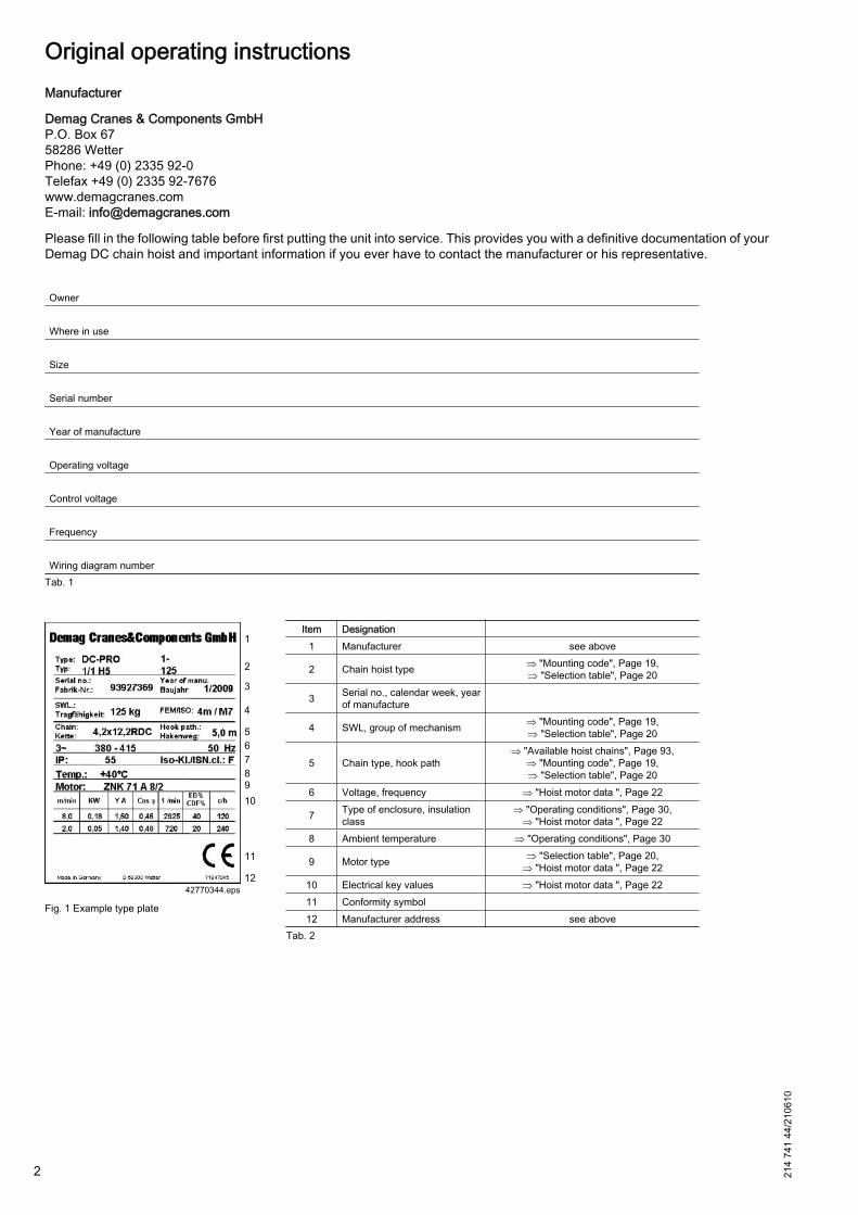
Please fill in the following table before first putting the unit into service. This provides you with a definitive documentation of yourDemag DC chain hoist and important information if you ever have to contact the manufacturer or his representative.
Owner Where in use Size Serial number Year of manufacture Operating voltage Control voltage Frequency Wiring diagram number
Tab. 1
Fig. 1 Example type plate
Item Designation 1 Manufacturer see above
2 Chain hoist type ⇒ "Mounting code", Page 19,⇒ "Selection table", Page 20
3 Serial no., calendar week, yearof manufacture
4 SWL, group of mechanism ⇒ "Mounting code", Page 19,⇒ "Selection table", Page 20
5 Chain type, hook path⇒ "Available hoist chains", Page 93,
⇒ "Mounting code", Page 19,⇒ "Selection table", Page 20
6 Voltage, frequency ⇒ "Hoist motor data ", Page 22
7 Type of enclosure, insulationclass
⇒ "Operating conditions", Page 30,⇒ "Hoist motor data ", Page 22
8 Ambient temperature ⇒ "Operating conditions", Page 30
9 Motor type ⇒ "Selection table", Page 20,⇒ "Hoist motor data ", Page 22
10 Electrical key values ⇒ "Hoist motor data ", Page 2211 Conformity symbol 12 Manufacturer address see above
Tab. 2
2 214
741
44/2
1061
0
Table of contents
General........................................................................................................................................................................ 7DC-Pro chain hoist ...................................................................................................................................................... 7DC-Pro documentation................................................................................................................................................ 7Symbols / signal words................................................................................................................................................ 7Information on the operating instructions .................................................................................................................... 8Liability and warranty................................................................................................................................................... 9Copyright ..................................................................................................................................................................... 9Use of spare parts ....................................................................................................................................................... 9Definition of personnel............................................................................................................................................... 10Test and inspection booklet....................................................................................................................................... 11Customer service ...................................................................................................................................................... 11
Safety ........................................................................................................................................................................ 12
General...................................................................................................................................................................... 12Safety signs on the equipment .................................................................................................................................. 12Intended use.............................................................................................................................................................. 12Hazards which may be caused by the machine ........................................................................................................ 13Responsibility of the owner ....................................................................................................................................... 14Operating personnel requirements............................................................................................................................ 14Personal protection equipment.................................................................................................................................. 15Emergency stop device ............................................................................................................................................. 15Regular inspections................................................................................................................................................... 15
Technical data ........................................................................................................................................................... 18
Design overview ........................................................................................................................................................ 18Mounting code........................................................................................................................................................... 19Selection table ........................................................................................................................................................... 20Electrical key values.................................................................................................................................................. 22Hoist motor data ....................................................................................................................................................... 22Mains connection delay fuse links............................................................................................................................. 24Supply lines ............................................................................................................................................................... 25Hook dimensions C ................................................................................................................................................... 26Noise emission / sound pressure level ...................................................................................................................... 28Transport, packing and storage................................................................................................................................. 28Safety instructions ..................................................................................................................................................... 28Scope of delivery ....................................................................................................................................................... 28Transport inspection.................................................................................................................................................. 28Packing...................................................................................................................................................................... 28Storage ..................................................................................................................................................................... 29Surface protection and painting................................................................................................................................. 29Operating conditions ................................................................................................................................................. 30
Technical description................................................................................................................................................. 31
Drive and brake ......................................................................................................................................................... 31Gearbox and slipping clutch ..................................................................................................................................... 31Chain drive ............................................................................................................................................................... 32Housing .................................................................................................................................................................... 32Electrical equipment .................................................................................................................................................. 32Control ....................................................................................................................................................................... 327-segment display for operating status and error display.......................................................................................... 33Software version, operating hours, number of cycles, operating statuses ................................................................ 33
11.11.21.31.41.51.61.71.81.91.10
2
2.12.22.32.42.52.62.72.82.9
3
3.13.23.33.43.4.13.4.23.4.33.53.63.73.7.13.7.23.7.33.7.43.7.53.83.9
4
4.14.24.34.44.54.5.14.5.24.5.3
214
741
44/2
1061
0
3

Central service enclosure.......................................................................................................................................... 34Control pendant height adjustment / control cable .................................................................................................... 35Control pendant ........................................................................................................................................................ 35Manulift DCM with quick-release coupling ............................................................................................................... 36Suspension................................................................................................................................................................ 38Trolley........................................................................................................................................................................ 40
Assembly ................................................................................................................................................................... 43
General...................................................................................................................................................................... 43Safety instructions for assembly................................................................................................................................ 43Tightening torques DC-Pro chain hoist ..................................................................................................................... 45Assembly procedure.................................................................................................................................................. 45Connecting the control pendant ................................................................................................................................ 46Suspending the chain hoist ....................................................................................................................................... 48Supporting structure .................................................................................................................................................. 48Suspension bracket ................................................................................................................................................... 48Screw plug, vent valve .............................................................................................................................................. 49Control cable ............................................................................................................................................................. 50Techncal data of the control cable ............................................................................................................................ 50Handling the control cable......................................................................................................................................... 50Height adjustment of the control pendant.................................................................................................................. 51Mobile control system................................................................................................................................................ 52Line connection ......................................................................................................................................................... 54Circuit diagrams and control cards............................................................................................................................ 56Circuit diagram DC-Pro 1 - 15 solo hoist ................................................................................................................... 56Circuit diagram DCM-Pro 1 - 5 solo hoist .................................................................................................................. 59Circuit diagram with E 11 - E 34 travel drive ............................................................................................................ 62Control board............................................................................................................................................................. 62Setting parameters with the control pendant............................................................................................................. 64General...................................................................................................................................................................... 64Meaning of keys ........................................................................................................................................................ 64Meaning of parameters ............................................................................................................................................. 64Starting parameter setting mode ............................................................................................................................... 65Setting the lower hook position ................................................................................................................................. 67
Putting the unit into service for the first time ............................................................................................................. 68
Safety instructions when first putting the unit into service......................................................................................... 68Inspection regulations ............................................................................................................................................... 68Inspections prior to putting into service for the first time ........................................................................................... 69Inspections when first putting into service, handing over .......................................................................................... 69
Operation................................................................................................................................................................... 70
Safety instructions for operation................................................................................................................................ 70Switching on .............................................................................................................................................................. 71Inspections when starting work ................................................................................................................................. 71Functional tests ......................................................................................................................................................... 71Operation................................................................................................................................................................... 72General...................................................................................................................................................................... 72Manulift ...................................................................................................................................................................... 75Emergency stop ........................................................................................................................................................ 76Taking out of service ................................................................................................................................................. 77Taking out of service in the case of faults ................................................................................................................. 77
4.64.74.84.94.104.11
5
5.15.25.35.45.55.65.6.15.6.25.75.85.8.15.8.25.8.35.8.45.95.105.10.15.10.25.10.35.10.45.115.11.15.11.25.11.35.11.45.12
6
6.16.26.36.4
7
7.17.27.2.17.2.27.37.3.17.3.27.47.57.5.14 214
741
44/2
1061
0

Taking the hoist out of service on finishing work....................................................................................................... 77Taking the unit out of service for maintenance and repairs....................................................................................... 77
Maintenance / repair.................................................................................................................................................. 78
Safety Instructions for maintenance / repair .............................................................................................................. 78Basic information on maintenance ............................................................................................................................ 79Routine inspections ................................................................................................................................................... 80Prescribed inspections .............................................................................................................................................. 80Service life of the contactor ....................................................................................................................................... 80Measures for achieving safe working periods S.W.P. ............................................................................................... 80General...................................................................................................................................................................... 80Calculating the actual duration of service S .............................................................................................................. 81Example: DC-Pro 10-1250 1/1 H5 V8/2 in 1Am ........................................................................................................ 82General overhaul GO ................................................................................................................................................ 84Inspection and maintenance schedule ...................................................................................................................... 84Maintenance work ..................................................................................................................................................... 86Suspension................................................................................................................................................................ 86Electrical equipment cover ........................................................................................................................................ 86Dismantling the chain collector box........................................................................................................................... 87Operating limit switches ............................................................................................................................................ 87Checking the operating limit switches ....................................................................................................................... 87Checking the operating limit switch actuator ............................................................................................................. 88Chain drive ................................................................................................................................................................ 89Checking the sprocket wheel .................................................................................................................................... 89Checking the chain guide .......................................................................................................................................... 89Checking the guide plate........................................................................................................................................... 89Checking the hoist chain ........................................................................................................................................... 90Scope of supply chain set ......................................................................................................................................... 92Available hoist chains................................................................................................................................................ 93Replacing the chain set ............................................................................................................................................. 94Lubricating the hoist chain......................................................................................................................................... 98Load hook................................................................................................................................................................ 100Checking the load hook........................................................................................................................................... 100Checking the return sprocket .................................................................................................................................. 100Replacing the hook assembly, reeving 1/1.............................................................................................................. 101Replacing the bottom block (standard for DC 10) with internal switch-off springs, reeving 2/1 .............................. 102Replacing the bottom block (standard for DC 15, option for DC 10) with external switch-off springs, reeving 2/1.103Manulift .................................................................................................................................................................... 103Checking the quick-release coupling....................................................................................................................... 103Replacing the chain................................................................................................................................................. 104Fitting the chain to the control unit .......................................................................................................................... 105Replacing the switching elements ........................................................................................................................... 107Replacing the gearbox ............................................................................................................................................ 108Load handling attachments ..................................................................................................................................... 108Buffers ..................................................................................................................................................................... 109Checking the switch-off buffer / switch-off spring .................................................................................................... 109Buffer design ........................................................................................................................................................... 110Brake ....................................................................................................................................................................... 113Brake assignment.................................................................................................................................................... 113Check brake wear ................................................................................................................................................... 113Slipping clutch ......................................................................................................................................................... 115Checking the slipping clutch.................................................................................................................................... 115Adjusting the slipping clutch .................................................................................................................................... 115Gearbox / oil change ............................................................................................................................................... 116Replacing the contactor on the control card............................................................................................................ 117Replacing cables ..................................................................................................................................................... 118Replacing the control cable ..................................................................................................................................... 118
7.5.27.5.3
8
8.18.28.38.3.18.3.28.3.38.3.3.18.3.3.28.3.3.38.3.48.48.58.5.18.5.28.5.38.5.48.5.4.18.5.4.28.5.58.5.5.18.5.5.28.5.5.38.5.5.48.5.5.58.5.5.68.5.5.78.5.5.88.5.68.5.6.18.5.6.28.5.6.38.5.6.48.5.6.5
8.5.78.5.7.18.5.7.28.5.7.38.5.7.48.5.7.58.5.7.68.5.88.5.8.18.5.8.28.5.98.5.9.18.5.9.28.5.108.5.10.18.5.10.28.5.118.5.128.5.138.5.13.1
214
741
44/2
1061
0
5
Replacing the helical cable...................................................................................................................................... 120
Faults / Warnings .................................................................................................................................................... 122
Safety instructions for faults / warnings................................................................................................................... 1227-segment display ................................................................................................................................................... 123General messages .................................................................................................................................................. 123Warning messages.................................................................................................................................................. 124Error messages ....................................................................................................................................................... 125
Disassembly / Disposal ........................................................................................................................................... 126
General.................................................................................................................................................................... 126
Accessories ............................................................................................................................................................. 127
Components ............................................................................................................................................................ 127
Spare parts .............................................................................................................................................................. 128
Overview ................................................................................................................................................................. 128Motor ....................................................................................................................................................................... 129Parts on gearbox ..................................................................................................................................................... 130Chain drive .............................................................................................................................................................. 132Hook assembly ........................................................................................................................................................ 134Bottom block with internal switch-off springs (standard) ......................................................................................... 135Bottom block with external switch-off springs (option) ............................................................................................ 136Electrical equipment cover ...................................................................................................................................... 137Manulift .................................................................................................................................................................... 138Control pendant, control cable, service cover ......................................................................................................... 140
Index......................................................................................................................................................................................... 141
8.5.13.2
9
9.19.29.39.49.5
10
10.1
11
11.1
12
12.112.212.312.412.512.612.712.812.912.10
6 214
741
44/2
1061
0
1 General
1.1 DC-Pro chain hoistYou have purchased a Demag quality product.
This chain hoist was manufactured to European standards and regulations in accordance with state-of-the-art en‐gineering principles. The requirements of the EC directive are complied with.
1.2 DC-Pro documentationFurther documents are available for sub-assemblies/components in addition to these operating instructions. If re‐quired, the corresponding documents are supplied or can be ordered separately, even if special designs or additionaloptions deviating from these operating instructions are ordered.
Documents1) Part no.:
Technical data / Catalogues
Demag DC-Pro 1 - 25 chain hoistDemag DCS-Pro 1 - 10 chain hoist 203 525 44
Demag DC-Com chain hoist 203 571 44CF5-DC/DCM trolley 203 568 44U11-DC/DCM/DK trolley 203 569 44E11-E34 DC travel drive (circuit diagrams) 203 698 44RU/EU56 trolley 203 691 44Electrical accessories DC 203 656 44Electrical accessories POLU box 203 682 44KBK classic (steel, powder-coated) 202 976 44KBK Aluline (anodized) 203 245 44KBK 0 + 25 trailing cable power supply 202 487 44KBK 0 + 25 power supply lines 202 386 44Clamp-fitted buffers 203 313 44
Operating instructions / Compo‐nent parts
DC-Pro 1 - 15 chain hoist 214 741 44DC-Pro 16 - 25 chain hoist 211 033 44DC-Com chain hoist 214 802 44DCS-Pro chain hoist 214 827 44DC-Di chain hoist 211 068 44DC-Wind chain hoist 211 010 44PGS parallel grippers 214 095 44
Assembly - Setting - Dimensions
E11-E34 DC travel drive 214 810 44KDC chain hoist 211 017 44KDDC/UDDC articulated trolley 211 159 44DRC-DC radio remote control 214 689 44DRC-DC quick-step instructions 211 045 44DC geared limit switch 211 011 44Friction force checking device 206 973 44DC PWM/3ST signal converter 211 094 44DSC-EX control pendant 214 832 44DSE10-C control pendant 214 998 44DC protective sleeve 203 673 44DC tandem box 211 108 44VG11-34 EU11-34 dual-output gearbox 211 122 44DSC strain relief 211 092 44
Test and inspection bookletDC test and inspection booklet 214 745 44Certificates 235 309 44
Tab. 3
1.3 Symbols / signal wordsImportant safety information and instructions are marked by corresponding symbols and signal words.
1) The documents can be ordered from the relevant Demag office.214
741
44/2
1061
0
7

The safety instructions must be followed. Exercise particular caution to ensure that accidents, injuries and damageare avoided in such cases.
The relevant local accident prevention regulations for the application and general safety instructions must also becomplied with.
The following symbols and instructions warn against possible personal injuries or damage to property and are in‐tended to assist you in your work.
DANGER
This symbol indicates an immediate hazard which can result in serious injury or death.– Follow these instructions at all times and be particularly careful and cautious.
WARNING
This symbol indicates a possibly hazardous situation which might result in serious injury or death.– Follow these instructions at all times and be particularly careful and cautious.
CAUTION
This symbol indicates a possibly hazardous situation which might result in medium to light injury or damage.– Follow these instructions at all times and be particularly careful and cautious.
Operating hazard for the machine● This symbol indicates information on the appropriate use of the machine.● This symbol in the operating instructions indicates all warnings which, if not complied with, may result in mal‐
functions or damage.
1.4 Information on the operating instructionsThese operating instructions are designed to provide the owner and operator with useful instructions for transpor‐tation, putting into service, operation and maintenance of our chain hoists. These operating instructions are anintegral part of the machine.
Persons entrusted with this work must know and comply with the safety regulations and the operating instructions.
The machine may only be operated by personnel who are fully familiar with the operating instructions. In particular,this includes the "Safety" chapter and the relevant safety instructions in the working sections of these operatinginstructions.
The operating instructions must be available to the operating personnel at all times in order to prevent operatingerrors and to ensure smooth and trouble-free operation of our products. They must be kept available in the immediatevicinity.
Demag chain hoists are supplied ready for operation as complete machine with a control pendant or as incompletemachine without control pendant.
Complete machine
Based on Machinery Directive 2006/42/EC, the chain hoist will in the following also be designated as machine inthe sense of a complete machine.
For a chain hoist delivered ready for operation in the sense of a complete machine, we confirm conformity with therequirements of Directive 2006/42/EC by means of the attached EC declaration of conformity.
8 214
741
44/2
1061
0
Incomplete machine
These instructions inform the manufacturer of an installation with a chain hoist on:● basic technical notes,● some typical risks,● the assembly and operation of the chain hoist.
The information contained herein may serve as basis for the risk analysis and the operating instructions which mustbe prepared by the manufacturer of the installation in compliance with the Machinery Directve.
For the operation of the installation, the manufacturer of the installation must provide additional operating instructionsas the result of the risk analysis, as required, and inform the owner about remaining hazards.
For a chain hoist as incomplete machine which is assembled with additional parts to form a machine that is readyfor operation, a declaration of incorporation will be enclosed. The declaration of incorporation refers to the scope ofdelivery of the incomplete or non-assembled machine. Before putting into operation the owner must take additionalmeasures, in order to meet the safety requirements for the machine.
Assembly of an incomplete or non-assembled chain hoist resulting in a machine ready for operation must be carriedout in compliance with the information of the manufacturer for the machine. The information for assembly and op‐eration of the chain hoist contained in these instructions must be complied with.
A conformity inspection in accordance with the Machinery Directive must be carried out for the assembled machinewhich is ready for operation and a declaration of conformity must be produced. For the conformity inspection, theinformation contained in the declaration of incorporation for the chain hoist may be used.
1.5 Liability and warrantyAll information included in these operating instructions has been compiled on the basis of the relevant regulations,state-of-the-art engineering principles and our many years of experience.
These operating instructions must be read carefully before starting any work on and with the chain hoist, especiallybefore it is put into service for the first time. The manufacturer does not assume any liability for damage resultingfrom the following:● non-compliance with the operating instructions,● inappropriate use,● untrained personnel,● unauthorized conversions,● technical modifications.
Wearing parts are not subject to liability for defects.
We reserve the right to incorporate technical modifications within the scope of improving the operating characteristicsand further development of the product.
1.6 CopyrightThese operating instructions are only intended to be used by people who work with or on the chain hoist.
Any and all content, texts, drawings, images and any other information are protected within the sense of copyrightlaw and are subject to further industrial rights. Any misuse is an offence.
No part of this documentation, in whole or in part, may be reproduced, distributed, shown in public or used in anyother way without specific prior consent. Infringements are an offence resulting in obligatory compensatory damages.Further rights reserved.
All industrial rights reserved.
1.7 Use of spare partsWe urgently recommend that only spare parts and accessories approved by us be used. Only then can we ensurethe safety and normal service life of the installation.
214
741
44/2
1061
0
9
Spare parts not approved by us may cause unpredictable hazards, damage, malfunctions or complete failure of thechain hoist.
The use of unauthorized spare parts may render any claims for guarantee, service, damages or liability against themanufacturer or his appointed personnel, dealers and representatives null and void.
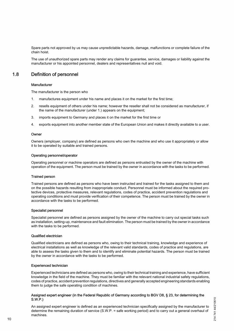
1.8 Definition of personnel
Manufacturer
The manufacturer is the person who
1. manufactures equipment under his name and places it on the market for the first time;
2. resells equipment of others under his name; however the reseller shall not be considered as manufacturer, ifthe name of the manufacturer (under 1.) appears on the equipment;
3. imports equipment to Germany and places it on the market for the first time or
4. exports equipment into another member state of the European Union and makes it directly available to a user.
Owner
Owners (employer, company) are defined as persons who own the machine and who use it appropriately or allowit to be operated by suitable and trained persons.
Operating personnel/operator
Operating personnel or machine operators are defined as persons entrusted by the owner of the machine withoperation of the equipment. The person must be trained by the owner in accordance with the tasks to be performed.
Trained person
Trained persons are defined as persons who have been instructed and trained for the tasks assigned to them andon the possible hazards resulting from inappropriate conduct. Personnel must be informed about the required pro‐tective devices, protective measures, relevant regulations, codes of practice, accident prevention regulations andoperating conditions and must provide verification of their competence. The person must be trained by the owner inaccordance with the tasks to be performed.
Specialist personnel
Specialist personnel are defined as persons assigned by the owner of the machine to carry out special tasks suchas installation, setting-up, maintenance and fault elimination. The person must be trained by the owner in accordancewith the tasks to be performed.
Qualified electrician
Qualified electricians are defined as persons who, owing to their technical training, knowledge and experience ofelectrical installations as well as knowledge of the relevant valid standards, codes of practice and regulations, areable to assess the tasks given to them and to identify and eliminate potential hazards. The person must be trainedby the owner in accordance with the tasks to be performed.
Experienced technician
Experienced technicians are defined as persons who, owing to their technical training and experience, have sufficientknowledge in the field of the machine. They must be familiar with the relevant national industrial safety regulations,codes of practice, accident prevention regulations, directives and generally accepted engineering standards enablingthem to judge the safe operating condition of machines.
Assigned expert engineer (in the Federal Republic of Germany according to BGV D8, § 23, for determining theS.W.P.)
An assigned expert engineer is defined as an experienced technician specifically assigned by the manufacturer todetermine the remaining duration of service (S.W.P. = safe working period) and to carry out a general overhaul ofmachines.
10 214
741
44/2
1061
0

Authorized expert engineer (according to BGV D6, § 28 in Germany)
In addition to the expert engineers of the Technical Supervisory and Inspection Board, an authorized expert engineerfor the inspection of machines is defined as an expert engineer authorized by the Industrial Employers’ MutualInsurance Association.
1.9 Test and inspection bookletA test and inspection booklet filled in with all details must be available for the hoist (in the Federal Repblic of Germanyaccording to BGV D6, § 28). The results of the regular tests and inspections must be entered into the test andinspection booklet and must be certified by the inspector. Test and inspection booklet ident. no.: ⇒ Tab. 3, Page 7.
1.10 Customer serviceOur after-sales service will provide you with technical information on our products, etc.
Please keep the serial or order number (see test and inspection booklet, load capacity plate on the crane) for anycorrespondence or spare part orders. Specifying this data ensures that you receive the correct information or therequired spare parts.
Demag Cranes & Components GmbH
Telephone +49 (0)180 / 5 - 741268
www.demagcranes.com
214
741
44/2
1061
0
11
2 Safety
2.1 GeneralThe "Safety" chapter provides an overview of all important safety aspects for optimum protection of personnel aswell as for safe and reliable operation of the machine.
At the time of placing it on the market the machine has been built according to the state-of-the-art and is consideredas safe to operate. However, it may cause hazards if it is used inappropriately by personnel which have not beentrained specially.
Knowledge of the contents of the operating instructions are one of the requirements necessary to protect personnelfrom hazards and to avoid malfunctions and, therefore, to operate the machine safely and reliably.
Modifications of any kind and additions to or conversions of the machine must not be carried out without the writtenconsent of Demag.
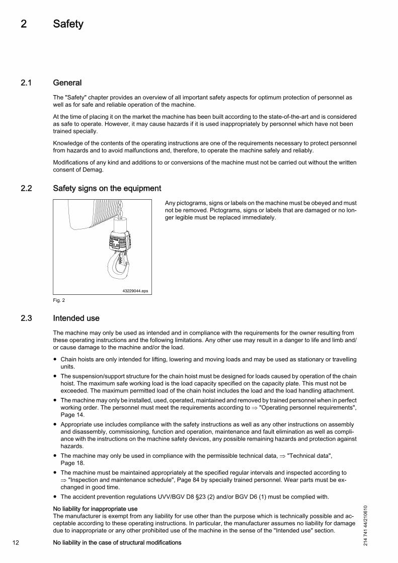
2.2 Safety signs on the equipment
43229044.eps
Fig. 2
Any pictograms, signs or labels on the machine must be obeyed and mustnot be removed. Pictograms, signs or labels that are damaged or no lon‐ger legible must be replaced immediately.
2.3 Intended useThe machine may only be used as intended and in compliance with the requirements for the owner resulting fromthese operating instructions and the following limitations. Any other use may result in a danger to life and limb and/or cause damage to the machine and/or the load.
● Chain hoists are only intended for lifting, lowering and moving loads and may be used as stationary or travellingunits.
● The suspension/support structure for the chain hoist must be designed for loads caused by operation of the chainhoist. The maximum safe working load is the load capacity specified on the capacity plate. This must not beexceeded. The maximum permitted load of the chain hoist includes the load and the load handling attachment.
● The machine may only be installed, used, operated, maintained and removed by trained personnel when in perfectworking order. The personnel must meet the requirements according to ⇒ "Operating personnel requirements",Page 14.
● Appropriate use includes compliance with the safety instructions as well as any other instructions on assemblyand disassembly, commissioning, function and operation, maintenance and fault elimination as well as compli‐ance with the instructions on the machine safety devices, any possible remaining hazards and protection againsthazards.
● The machine may only be used in compliance with the permissible technical data, ⇒ "Technical data",Page 18.
● The machine must be maintained appropriately at the specified regular intervals and inspected according to⇒ "Inspection and maintenance schedule", Page 84 by specially trained personnel. Wear parts must be ex‐changed in good time.
● The accident prevention regulations UVV/BGV D8 §23 (2) and/or BGV D6 (1) must be complied with.
No liability for inappropriate useThe manufacturer is exempt from any liability for use other than the purpose which is technically possible and ac‐ceptable according to these operating instructions. In particular, the manufacturer assumes no liability for damagedue to inappropriate or any other prohibited use of the machine in the sense of the "Intended use" section.
No liability in the case of structural modifications12 214
741
44/2
1061
0
The manufacturer is not liable for unauthorized structural modifications which have not been agreed with him. Thisincludes incorrect connection of the machine to devices or equipment that do not belong to our scope of delivery, orthe installation or use of accessories, equipment or sub-assemblies of other manufacturers that are not approvedby the manufacturer.
Depending on the type and scope of the machine, an inspection must be carried out by an expert engineer beforehanding it over to the owner.DC-Pro chain hoists are designed for operation at temperatures of -20 °C up to +45 °C. At extreme temperaturesand in aggressive atmophere or under conditions deviating from the section "Operating conditions", special meas‐ures must be taken by the owner in agreement with Demag.
Use of the control pendantPowered lifting and lowering and, if applicable, cross-travel and long-travel motions are controlled by means of thecorresponding control elements on the control unit. The slow speeds are intended for attaching the load, lifting it freeand depositing it. Loads can be precisely positioned at slow speeds.Short transport times can be achieved at higher speeds. They are suitable for travelling without a load or with asafely suspended load if no hazard can be caused by the faster motion sequences.
Inching must be avoided, as it causes increased wear and load sway.
2.4 Hazards which may be caused by the machineThe machine has been subject to a risk analysis. The design and execution based on this analysis corresponds tostate-of-the-art engineering principles. Nevertheless there are residual risks!
The machine is operated at high electrical voltage.
DANGER
Live componentsDanger to life and limb.Electrical energy may cause serious injuries. If the insulation or individual components are damaged, there isdanger to life caused by electrical current.– Before carrying out maintenance, cleaning or repair work, switch off the machine and secure against restarting.– Switch off the power supply when carrying out any work on the electrical installation. Check the components
to be replaced for being de-energized.– Do not remove safety equipment or render it inoperative by modifications.
WARNING
Crushing hazardThe lifting or lowering of loads may cause crushing hazards for parts of the body.When lifting or lowering loads, it must be ensured that no persons are in the immediate danger zone.
WARNING
Suspended load! Falling parts!There is danger to life and limb, when lifted loads fall down.Persons must keep out of the danger zone.– Keep a sufficient safety distance.– Do not walk under the suspended load.
Certain work and practices are prohibited when using the machine as they may involve danger to life and limb andresult in lasting damage to the machine. Please note the safety instructions in the chapters:● ⇒ "Assembly", Page 43● ⇒ "Putting the unit into service for the first time", Page 68
214
741
44/2
1061
0
13

● ⇒ "Operation", Page 70● ⇒ "Maintenance / repair", Page 78
2.5 Responsibility of the ownerInformation on safety at work refers to the regulations of the European Union that apply when the machine is man‐ufactured. The owner is obliged to ensure that the specified industrial safety measures comply with the latest rulesand regulations and to observe new regulations during the entire service life of the machine. Local industrial safetylegislation and regional regulations and codes of practice must be observed outside the European Union.
General safety, accident prevention and environmental protection regulations that apply where the machine is inoperation must be observed and complied with in addition to the safety instructions contained in these operatinginstructions.
The owner and any personnel authorised by him are responsible for correct operation of the machine and for clearlydefining responsibilities for installation, operation, maintenance and cleaning. The operating instructions must befollowed in full and without any limitations.
Special local conditions or applications can lead to situations which are not considered in these operating instruc‐tions. In such cases, the required safety measures must be defined and implemented by the owner. Necessarymeasures may also relate, for example, to the handling of hazardous materials or tools and the provision/wearingof personal protection equipment. The operating instructions must, if required, be supplemented by the owner withinstructions relating to the organization of work, working procedures, authorized personnel, supervising and reportingobligations, etc. For further information please refer to ⇒ "Safety instructions for operation", Page 70.
Furthermore, the owner must ensure that● any further working and safety instructions resulting from risk assessment of the machine workplaces are specified
in operating procedures.● personnel who work with or on the machine are provided with appropriate first-aid equipment. The personnel
must be trained in the use of the first-aid equipment.● the operating instructions are always kept available in the immediate vicinity of the machine for installation, op‐
erating, maintenance and cleaning personnel.● the personnel are trained in accordance with the work to be performed.● the machine is only operated when in safe and proper working order.● the safety devices are always kept freely accessible and are checked regularly.● the national regulations for the operation of cranes and lifting applinces are observed.● the specified regular checks and inspections are carried out on time and are documented.
The owner is urged to develop procedures and guidelines to cover malfunction situations, to instruct users and toapply these instructions at a suitable place in a readily legible manner.
2.6 Operating personnel requirementsOnly authorised and trained personnel may operate the machine. The personnel must have received instruction onthe machine functions and any hazards that may occur.
Every individual given the task of working on or with the machine must have read and understood the operatinginstructions before any work is started.
Persons under the influence of drugs, alcohol or medicines which affect their reactions must not work on or with themachine.
Age and job-specific regulations relevant at the place where the machine is operated must be observed for theselection of any personnel.
Personnel are obliged to report to the owner without delay any changes to the machine that impair safety.
For independent operation (machine operator) or maintenance (trained maintenance fitter) of the DC-Pro chain hoist,the owner may only employ persons● who are at least 18 years of age,
14 214
741
44/2
1061
0
● who are mentally and physically suitable,● who have been instructed in the operation and maintenance of chain hoists and who have proven their qualification
to the owner in this respect.
2.7 Personal protection equipmentWhen work is carried out on or with the machine, the following must always be worn:● Protective equipment, closely-fitting working clothes (low tear strength, no loose sleeves, no rings or any other
jewellery, etc.);● Safety shoes to protect against heavy falling parts and against slipping;● Safety helmet for all persons in the danger zone;
2.8 Emergency stop device
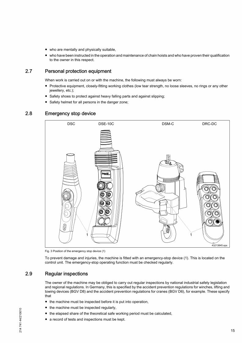
Fig. 3 Position of the emergency stop device (1)
To prevent damage and injuries, the machine is fitted with an emergency-stop device (1). This is located on thecontrol unit. The emergency-stop operating function must be checked regularly.
2.9 Regular inspectionsThe owner of the machine may be obliged to carry out regular inspections by national industrial safety legislationand regional regulations. In Germany, this is specified by the accident prevention regulations for winches, lifting andtowing devices (BGV D8) and the accident prevention regulations for cranes (BGV D6), for example. These specifythat● the machine must be inspected before it is put into operation,● the machine must be inspected regularly,● the elapsed share of the theoretical safe working period must be calculated,● a record of tests and inspections must be kept.
214
741
44/2
1061
0
15

The owner is obliged to ensure that the machine complies with the latest rules and regulations and to observe newregulations at all times.
If no comparable inspection regulations or requirements apply at the place where the machine is operated, werecommend compliance with the above-mentioned regulations.
16 214
741
44/2
1061
0

214
741
44/2
1061
0
17
3 Technical data
3.1 Design overview
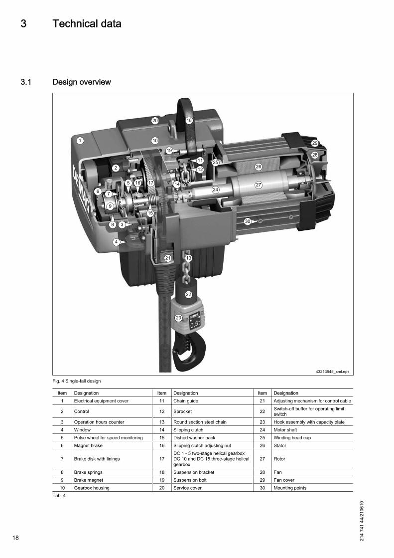
Fig. 4 Single-fall design
Item Designation Item Designation Item Designation1 Electrical equipment cover 11 Chain guide 21 Adjusting mechanism for control cable
2 Control 12 Sprocket 22 Switch-off buffer for operating limitswitch
3 Operation hours counter 13 Round section steel chain 23 Hook assembly with capacity plate4 Window 14 Slipping clutch 24 Motor shaft5 Pulse wheel for speed monitoring 15 Dished washer pack 25 Winding head cap6 Magnet brake 16 Slipping clutch adjusting nut 26 Stator
7 Brake disk with linings 17DC 1 - 5 two-stage helical gearboxDC 10 and DC 15 three-stage helicalgearbox
27 Rotor
8 Brake springs 18 Suspension bracket 28 Fan9 Brake magnet 19 Suspension bolt 29 Fan cover10 Gearbox housing 20 Service cover 30 Mounting points
Tab. 4
18 214
741
44/2
1061
0
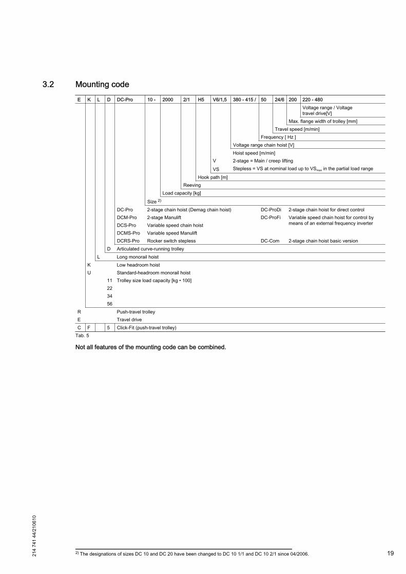
3.2 Mounting codeE K L D DC-Pro 10 - 2000 2/1 H5 V6/1,5 380 - 415 / 50 24/6 200 220 - 480
Voltage range / Voltagetravel drive[V]
Max. flange width of trolley [mm]Travel speed [m/min]
Frequency [ Hz ]Voltage range chain hoist [V]
Hoist speed [m/min]V 2-stage = Main / creep lifting
VS Stepless = VS at nominal load up to VSmax in the partial load range
Hook path [m]Reeving
Load capacity [kg]
Size 2)
DC-Pro 2-stage chain hoist (Demag chain hoist) DC-ProDi 2-stage chain hoist for direct controlDCM-Pro 2-stage Manulift DC-ProFi Variable speed chain hoist for control by
means of an external frequency inverterDCS-Pro Variable speed chain hoist DCMS-Pro Variable speed Manulift DCRS-Pro Rocker switch stepless DC-Com 2-stage chain hoist basic version
D Articulated curve-running trolleyL Long monorail hoist
K Low headroom hoistU Standard-headroom monorail hoist 11 Trolley size load capacity [kg • 100] 22 34 56
R Push-travel trolleyE Travel driveC F 5 Click-Fit (push-travel trolley)
Tab. 5
Not all features of the mounting code can be combined.
2) The designations of sizes DC 10 and DC 20 have been changed to DC 10 1/1 and DC 10 2/1 since 04/2006.214
741
44/2
1061
0
19
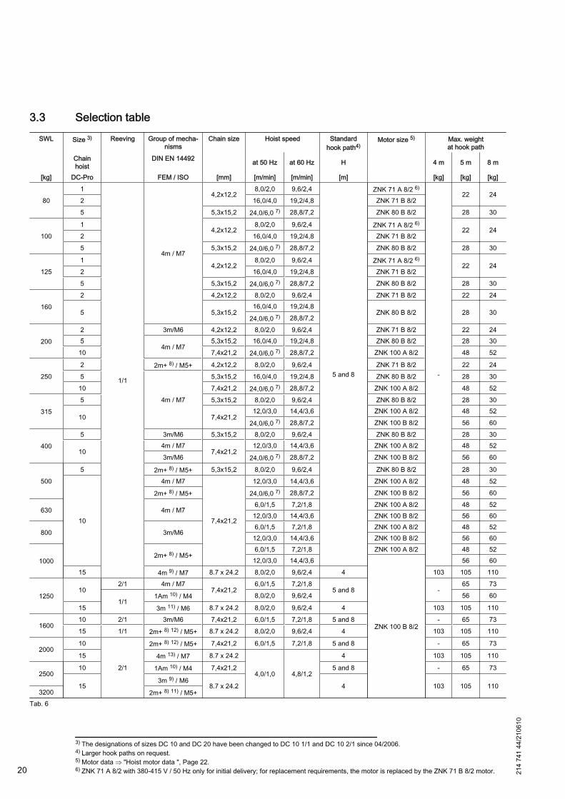
3.3 Selection tableSWL Size 3) Reeving Group of mecha‐
nismsChain size Hoist speed Standard
hook path4)Motor size 5) Max. weight
at hook pathChainhoist
DIN EN 14492 at 50 Hz at 60 Hz H 4 m 5 m 8 m
[kg] DC-Pro FEM / ISO [mm] [m/min] [m/min] [m] [kg] [kg] [kg]
801
1/1
4m / M7
4,2x12,28,0/2,0 9,6/2,4
5 and 8
ZNK 71 A 8/2 6)
-
22 242 16,0/4,0 19,2/4,8 ZNK 71 B 8/25 5,3x15,2 24,0/6,0 7) 28,8/7,2 ZNK 80 B 8/2 28 30
1001
4,2x12,28,0/2,0 9,6/2,4 ZNK 71 A 8/2 6)
22 242 16,0/4,0 19,2/4,8 ZNK 71 B 8/25 5,3x15,2 24,0/6,0 7) 28,8/7,2 ZNK 80 B 8/2 28 30
1251
4,2x12,28,0/2,0 9,6/2,4 ZNK 71 A 8/2 6)
22 242 16,0/4,0 19,2/4,8 ZNK 71 B 8/25 5,3x15,2 24,0/6,0 7) 28,8/7,2 ZNK 80 B 8/2 28 30
1602 4,2x12,2 8,0/2,0 9,6/2,4 ZNK 71 B 8/2 22 24
5 5,3x15,216,0/4,0 19,2/4,8
ZNK 80 B 8/2 28 3024,0/6,0 7) 28,8/7,2
2002 3m/M6 4,2x12,2 8,0/2,0 9,6/2,4 ZNK 71 B 8/2 22 245
4m / M75,3x15,2 16,0/4,0 19,2/4,8 ZNK 80 B 8/2 28 30
10 7,4x21,2 24,0/6,0 7) 28,8/7,2 ZNK 100 A 8/2 48 52
2502 2m+ 8) / M5+ 4,2x12,2 8,0/2,0 9,6/2,4 ZNK 71 B 8/2 22 245
4m / M7
5,3x15,2 16,0/4,0 19,2/4,8 ZNK 80 B 8/2 28 30
10 7,4x21,2 24,0/6,0 7) 28,8/7,2 ZNK 100 A 8/2 48 52
3155 5,3x15,2 8,0/2,0 9,6/2,4 ZNK 80 B 8/2 28 30
10 7,4x21,212,0/3,0 14,4/3,6 ZNK 100 A 8/2 48 52
24,0/6,0 7) 28,8/7,2 ZNK 100 B 8/2 56 60
4005 3m/M6 5,3x15,2 8,0/2,0 9,6/2,4 ZNK 80 B 8/2 28 30
104m / M7
7,4x21,212,0/3,0 14,4/3,6 ZNK 100 A 8/2 48 52
3m/M6 24,0/6,0 7) 28,8/7,2 ZNK 100 B 8/2 56 60
5005 2m+ 8) / M5+ 5,3x15,2 8,0/2,0 9,6/2,4 ZNK 80 B 8/2 28 30
10
4m / M7
7,4x21,2
12,0/3,0 14,4/3,6 ZNK 100 A 8/2 48 52
2m+ 8) / M5+ 24,0/6,0 7) 28,8/7,2 ZNK 100 B 8/2 56 60
630 4m / M76,0/1,5 7,2/1,8 ZNK 100 A 8/2 48 52
12,0/3,0 14,4/3,6 ZNK 100 B 8/2 56 60
800 3m/M66,0/1,5 7,2/1,8 ZNK 100 A 8/2 48 52
12,0/3,0 14,4/3,6 ZNK 100 B 8/2 56 60
10002m+ 8) / M5+
6,0/1,5 7,2/1,8 ZNK 100 A 8/2 48 5212,0/3,0 14,4/3,6
ZNK 100 B 8/2
56 6015 4m 9) / M7 8.7 x 24.2 8,0/2,0 9,6/2,4 4 103 105 110
125010
2/1 4m / M77,4x21,2
6,0/1,5 7,2/1,85 and 8 -
65 73
1/11Am 10) / M4 8,0/2,0 9,6/2,4 56 60
15 3m 11) / M6 8.7 x 24.2 8,0/2,0 9,6/2,4 4 103 105 110
160010 2/1 3m/M6 7,4x21,2 6,0/1,5 7,2/1,8 5 and 8 - 65 7315 1/1 2m+ 8) 12) / M5+ 8.7 x 24.2 8,0/2,0 9,6/2,4 4 103 105 110
200010
2/1
2m+ 8) 12) / M5+ 7,4x21,2 6,0/1,5 7,2/1,8 5 and 8 - 65 73
15 4m 13) / M7 8.7 x 24.2
4,0/1,0 4,8/1,2
4 103 105 110
250010 1Am 10) / M4 7,4x21,2 5 and 8 - 65 73
153m 9) / M6
8.7 x 24.2 4 103 105 1103200 2m+ 8) 11) / M5+
Tab. 6
3) The designations of sizes DC 10 and DC 20 have been changed to DC 10 1/1 and DC 10 2/1 since 04/2006.4) Larger hook paths on request.5) Motor data ⇒ "Hoist motor data ", Page 22.6) ZNK 71 A 8/2 with 380-415 V / 50 Hz only for initial delivery; for replacement requirements, the motor is replaced by the ZNK 71 B 8/2 motor.20 21
4 74
1 44
/210
610
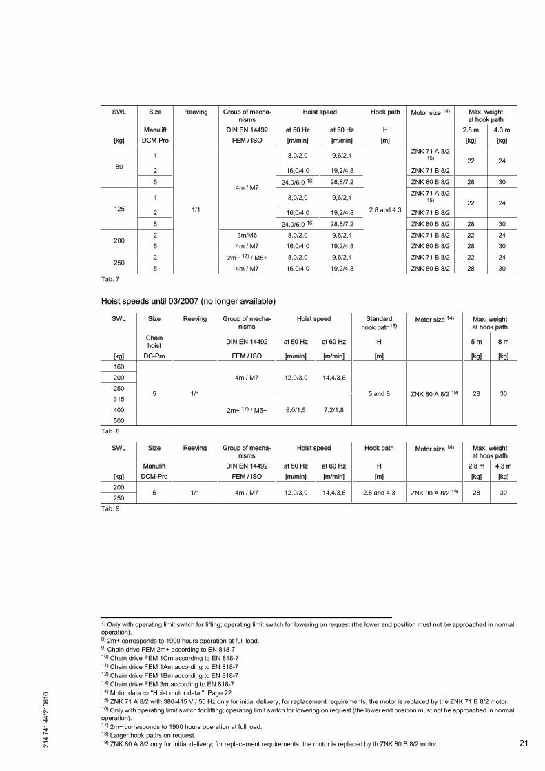
SWL Size Reeving Group of mecha‐nisms
Hoist speed Hook path Motor size 14) Max. weightat hook path
Manulift DIN EN 14492 at 50 Hz at 60 Hz H 2.8 m 4.3 m[kg] DCM-Pro FEM / ISO [m/min] [m/min] [m] [kg] [kg]
801
1/1
4m / M7
8,0/2,0 9,6/2,4
2.8 and 4.3
ZNK 71 A 8/215) 22 24
2 16,0/4,0 19,2/4,8 ZNK 71 B 8/25 24,0/6,0 16) 28,8/7,2 ZNK 80 B 8/2 28 30
1251 8,0/2,0 9,6/2,4 ZNK 71 A 8/2
15) 22 242 16,0/4,0 19,2/4,8 ZNK 71 B 8/2
5 24,0/6,0 16) 28,8/7,2 ZNK 80 B 8/2 28 30
2002 3m/M6 8,0/2,0 9,6/2,4 ZNK 71 B 8/2 22 245 4m / M7 16,0/4,0 19,2/4,8 ZNK 80 B 8/2 28 30
2502 2m+ 17) / M5+ 8,0/2,0 9,6/2,4 ZNK 71 B 8/2 22 245 4m / M7 16,0/4,0 19,2/4,8 ZNK 80 B 8/2 28 30
Tab. 7
Hoist speeds until 03/2007 (no longer available)
SWL Size Reeving Group of mecha‐nisms
Hoist speed Standardhook path18)
Motor size 14) Max. weightat hook path
Chainhoist DIN EN 14492 at 50 Hz at 60 Hz H 5 m 8 m
[kg] DC-Pro FEM / ISO [m/min] [m/min] [m] [kg] [kg]160
5 1/1
4m / M7 12,0/3,0 14,4/3,6
5 and 8 ZNK 80 A 8/2 19) 28 30
200250315
2m+ 17) / M5+ 6,0/1,5 7,2/1,8400500
Tab. 8
SWL Size Reeving Group of mecha‐nisms
Hoist speed Hook path Motor size 14) Max. weightat hook path
Manulift DIN EN 14492 at 50 Hz at 60 Hz H 2.8 m 4.3 m[kg] DCM-Pro FEM / ISO [m/min] [m/min] [m] [kg] [kg]200
5 1/1 4m / M7 12,0/3,0 14,4/3,6 2.8 and 4.3 ZNK 80 A 8/2 19) 28 30250
Tab. 9
7) Only with operating limit switch for lifting; operating limit switch for lowering on request (the lower end position must not be approached in normaloperation).8) 2m+ corresponds to 1900 hours operation at full load.9) Chain drive FEM 2m+ according to EN 818-710) Chain drive FEM 1Cm according to EN 818-711) Chain drive FEM 1Am according to EN 818-712) Chain drive FEM 1Bm according to EN 818-713) Chain drive FEM 3m according to EN 818-714) Motor data ⇒ "Hoist motor data ", Page 22.15) ZNK 71 A 8/2 with 380-415 V / 50 Hz only for initial delivery; for replacement requirements, the motor is replaced by the ZNK 71 B 8/2 motor.16) Only with operating limit switch for lifting; operating limit switch for lowering on request (the lower end position must not be approached in normaloperation).17) 2m+ corresponds to 1900 hours operation at full load.18) Larger hook paths on request.19) ZNK 80 A 8/2 only for initial delivery; for replacement requirements, the motor is replaced by th ZNK 80 B 8/2 motor.21
4 74
1 44
/210
610
21
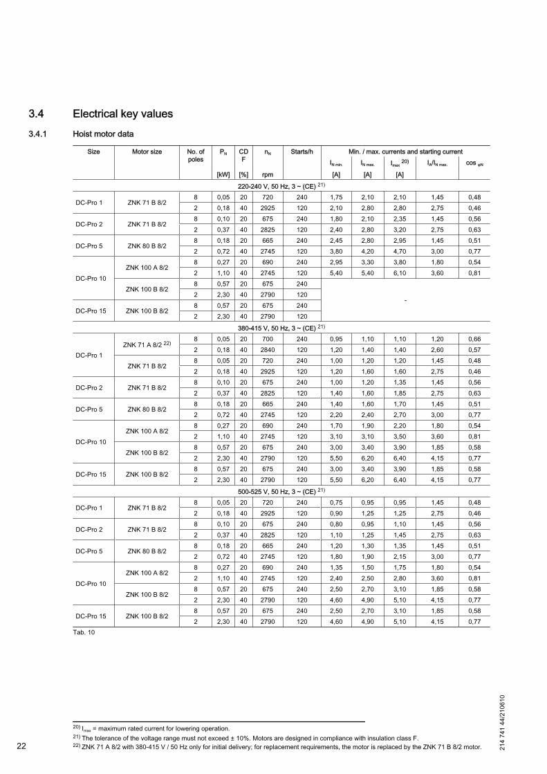
3.4 Electrical key values3.4.1 Hoist motor data
Size Motor size No. ofpoles
PN CDF
nN Starts/h Min. / max. currents and starting currentIN min. IN max. Imax 20) IA/IN max. cos φN
[kW] [%] rpm [A] [A] [A]
220-240 V, 50 Hz, 3 ~ (CE) 21)
DC-Pro 1 ZNK 71 B 8/28 0,05 20 720 240 1,75 2,10 2,10 1,45 0,482 0,18 40 2925 120 2,10 2,80 2,80 2,75 0,46
DC-Pro 2 ZNK 71 B 8/28 0,10 20 675 240 1,80 2,10 2,35 1,45 0,562 0,37 40 2825 120 2,40 2,80 3,20 2,75 0,63
DC-Pro 5 ZNK 80 B 8/28 0,18 20 665 240 2,45 2,80 2,95 1,45 0,512 0,72 40 2745 120 3,80 4,20 4,70 3,00 0,77
DC-Pro 10ZNK 100 A 8/2
8 0,27 20 690 240 2,95 3,30 3,80 1,80 0,542 1,10 40 2745 120 5,40 5,40 6,10 3,60 0,81
ZNK 100 B 8/28 0,57 20 675 240
-2 2,30 40 2790 120
DC-Pro 15 ZNK 100 B 8/28 0,57 20 675 2402 2,30 40 2790 120
380-415 V, 50 Hz, 3 ~ (CE) 21)
DC-Pro 1ZNK 71 A 8/2 22)
8 0,05 20 700 240 0,95 1,10 1,10 1,20 0,662 0,18 40 2840 120 1,20 1,40 1,40 2,60 0,57
ZNK 71 B 8/28 0,05 20 720 240 1,00 1,20 1,20 1,45 0,482 0,18 40 2925 120 1,20 1,60 1,60 2,75 0,46
DC-Pro 2 ZNK 71 B 8/28 0,10 20 675 240 1,00 1,20 1,35 1,45 0,562 0,37 40 2825 120 1,40 1,60 1,85 2,75 0,63
DC-Pro 5 ZNK 80 B 8/28 0,18 20 665 240 1,40 1,60 1,70 1,45 0,512 0,72 40 2745 120 2,20 2,40 2,70 3,00 0,77
DC-Pro 10ZNK 100 A 8/2
8 0,27 20 690 240 1,70 1,90 2,20 1,80 0,542 1,10 40 2745 120 3,10 3,10 3,50 3,60 0,81
ZNK 100 B 8/28 0,57 20 675 240 3,00 3,40 3,90 1,85 0,582 2,30 40 2790 120 5,50 6,20 6,40 4,15 0,77
DC-Pro 15 ZNK 100 B 8/28 0,57 20 675 240 3,00 3,40 3,90 1,85 0,582 2,30 40 2790 120 5,50 6,20 6,40 4,15 0,77
500-525 V, 50 Hz, 3 ~ (CE) 21)
DC-Pro 1 ZNK 71 B 8/28 0,05 20 720 240 0,75 0,95 0,95 1,45 0,482 0,18 40 2925 120 0,90 1,25 1,25 2,75 0,46
DC-Pro 2 ZNK 71 B 8/28 0,10 20 675 240 0,80 0,95 1,10 1,45 0,562 0,37 40 2825 120 1,10 1,25 1,45 2,75 0,63
DC-Pro 5 ZNK 80 B 8/28 0,18 20 665 240 1,20 1,30 1,35 1,45 0,512 0,72 40 2745 120 1,80 1,90 2,15 3,00 0,77
DC-Pro 10ZNK 100 A 8/2
8 0,27 20 690 240 1,35 1,50 1,75 1,80 0,542 1,10 40 2745 120 2,40 2,50 2,80 3,60 0,81
ZNK 100 B 8/28 0,57 20 675 240 2,50 2,70 3,10 1,85 0,582 2,30 40 2790 120 4,60 4,90 5,10 4,15 0,77
DC-Pro 15 ZNK 100 B 8/28 0,57 20 675 240 2,50 2,70 3,10 1,85 0,582 2,30 40 2790 120 4,60 4,90 5,10 4,15 0,77
Tab. 10
20) Imax = maximum rated current for lowering operation.21) The tolerance of the voltage range must not exceed ± 10%. Motors are designed in compliance with insulation class F.22) ZNK 71 A 8/2 with 380-415 V / 50 Hz only for initial delivery; for replacement requirements, the motor is replaced by the ZNK 71 B 8/2 motor.22 21
4 74
1 44
/210
610
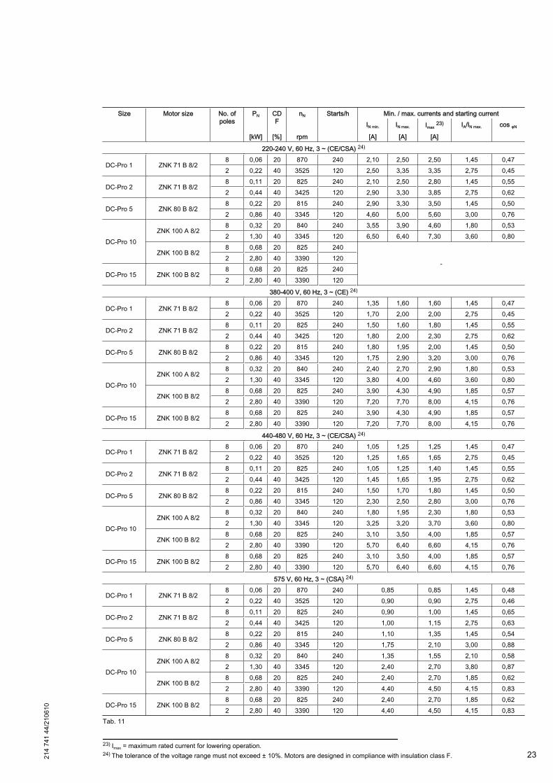
Size Motor size No. ofpoles
PN CDF
nN Starts/h Min. / max. currents and starting currentIN min. IN max. Imax 23) IA/IN max. cos φN
[kW] [%] rpm [A] [A] [A]
220-240 V, 60 Hz, 3 ~ (CE/CSA) 24)
DC-Pro 1 ZNK 71 B 8/28 0,06 20 870 240 2,10 2,50 2,50 1,45 0,472 0,22 40 3525 120 2,50 3,35 3,35 2,75 0,45
DC-Pro 2 ZNK 71 B 8/28 0,11 20 825 240 2,10 2,50 2,80 1,45 0,552 0,44 40 3425 120 2,90 3,30 3,85 2,75 0,62
DC-Pro 5 ZNK 80 B 8/28 0,22 20 815 240 2,90 3,30 3,50 1,45 0,502 0,86 40 3345 120 4,60 5,00 5,60 3,00 0,76
DC-Pro 10ZNK 100 A 8/2
8 0,32 20 840 240 3,55 3,90 4,60 1,80 0,532 1,30 40 3345 120 6,50 6,40 7,30 3,60 0,80
ZNK 100 B 8/28 0,68 20 825 240
-2 2,80 40 3390 120
DC-Pro 15 ZNK 100 B 8/28 0,68 20 825 2402 2,80 40 3390 120
380-400 V, 60 Hz, 3 ~ (CE) 24)
DC-Pro 1 ZNK 71 B 8/28 0,06 20 870 240 1,35 1,60 1,60 1,45 0,472 0,22 40 3525 120 1,70 2,00 2,00 2,75 0,45
DC-Pro 2 ZNK 71 B 8/28 0,11 20 825 240 1,50 1,60 1,80 1,45 0,552 0,44 40 3425 120 1,80 2,00 2,30 2,75 0,62
DC-Pro 5 ZNK 80 B 8/28 0,22 20 815 240 1,80 1,95 2,00 1,45 0,502 0,86 40 3345 120 1,75 2,90 3,20 3,00 0,76
DC-Pro 10ZNK 100 A 8/2
8 0,32 20 840 240 2,40 2,70 2,90 1,80 0,532 1,30 40 3345 120 3,80 4,00 4,60 3,60 0,80
ZNK 100 B 8/28 0,68 20 825 240 3,90 4,30 4,90 1,85 0,572 2,80 40 3390 120 7,20 7,70 8,00 4,15 0,76
DC-Pro 15 ZNK 100 B 8/28 0,68 20 825 240 3,90 4,30 4,90 1,85 0,572 2,80 40 3390 120 7,20 7,70 8,00 4,15 0,76
440-480 V, 60 Hz, 3 ~ (CE/CSA) 24)
DC-Pro 1 ZNK 71 B 8/28 0,06 20 870 240 1,05 1,25 1,25 1,45 0,472 0,22 40 3525 120 1,25 1,65 1,65 2,75 0,45
DC-Pro 2 ZNK 71 B 8/28 0,11 20 825 240 1,05 1,25 1,40 1,45 0,552 0,44 40 3425 120 1,45 1,65 1,95 2,75 0,62
DC-Pro 5 ZNK 80 B 8/28 0,22 20 815 240 1,50 1,70 1,80 1,45 0,502 0,86 40 3345 120 2,30 2,50 2,80 3,00 0,76
DC-Pro 10ZNK 100 A 8/2
8 0,32 20 840 240 1,80 1,95 2,30 1,80 0,532 1,30 40 3345 120 3,25 3,20 3,70 3,60 0,80
ZNK 100 B 8/28 0,68 20 825 240 3,10 3,50 4,00 1,85 0,572 2,80 40 3390 120 5,70 6,40 6,60 4,15 0,76
DC-Pro 15 ZNK 100 B 8/28 0,68 20 825 240 3,10 3,50 4,00 1,85 0,572 2,80 40 3390 120 5,70 6,40 6,60 4,15 0,76
575 V, 60 Hz, 3 ~ (CSA) 24)
DC-Pro 1 ZNK 71 B 8/28 0,06 20 870 240 0,85 0,85 1,45 0,482 0,22 40 3525 120 0,90 0,90 2,75 0,46
DC-Pro 2 ZNK 71 B 8/28 0,11 20 825 240 0,90 1,00 1,45 0,652 0,44 40 3425 120 1,00 1,15 2,75 0,63
DC-Pro 5 ZNK 80 B 8/28 0,22 20 815 240 1,10 1,35 1,45 0,542 0,86 40 3345 120 1,75 2,10 3,00 0,88
DC-Pro 10ZNK 100 A 8/2
8 0,32 20 840 240 1,35 1,55 2,10 0,582 1,30 40 3345 120 2,40 2,70 3,80 0,87
ZNK 100 B 8/28 0,68 20 825 240 2,40 2,70 1,85 0,622 2,80 40 3390 120 4,40 4,50 4,15 0,83
DC-Pro 15 ZNK 100 B 8/28 0,68 20 825 240 2,40 2,70 1,85 0,622 2,80 40 3390 120 4,40 4,50 4,15 0,83
Tab. 11
23) Imax = maximum rated current for lowering operation.24) The tolerance of the voltage range must not exceed ± 10%. Motors are designed in compliance with insulation class F.21
4 74
1 44
/210
610
23

Hoist speeds until 03/2007 (no longer available)
Size Motor size No. ofpoles
PN CDF
nN Starts/h Min. / max. currents and starting currentIN min. IN max. Imax 25) IA/IN max. cos φN
[kW] [%] rpm [A] [A] [A]
220-240 V, 50 Hz, 3 ~ (CE) 26)
DC-Pro 5DCM-Pro 5 ZNK 80 A 8/2
8 0,14 20 710 240 2,00 2,20 2,50 2,10 0,482 0,56 40 2880 120 4,15 5,00 5,90 4,35 0,57
380-415 V, 50 Hz, 3 ~ (CE) 26)
DC-Pro 5DCM-Pro 5 ZNK 80 A 8/2
8 0,14 20 710 240 1,15 1,30 1,45 2,10 0,482 0,56 40 2880 120 2,40 2,90 3,40 4,35 0,57
500-525 V, 50 Hz, 3 ~ (CE) 26)
DC-Pro 5DCM-Pro 5 ZNK 80 A 8/2
8 0,14 20 710 240 0,95 1,05 1,15 2,10 0,482 0,56 40 2880 120 1,90 2,30 2,70 4,35 0,57
220-240 V, 60 Hz, 3 ~ (CE/CSA) 26)
DC-Pro 5DCM-Pro 5 ZNK 80 A 8/2
8 0,17 20 860 240 2,40 2,70 3,00 2,10 0,472 0,67 40 3480 120 5,00 6,00 7,10 4,35 0,56
380-400 V, 60 Hz, 3 ~ (CE) 26)
DC-Pro 5DCM-Pro 5 ZNK 80 A 8/2
8 0,17 20 860 240 1,50 1,60 1,80 2,10 0,472 0,67 40 3480 120 3,40 3,50 4,10 4,35 0,56
440-480 V, 60 Hz, 3 ~ (CE/CSA) 26)
DC-Pro 5DCM-Pro 5 ZNK 80 A 8/2
8 0,17 20 860 240 1,20 1,35 1,50 2,10 0,472 0,67 40 3480 120 2,50 3,00 3,55 4,35 0,56
575 V, 60 Hz, 3 ~ (CSA) 26)
DC-Pro 5DCM-Pro 5 ZNK 80 A 8/2
8 0,17 20 860 240 0,91 1,00 2,10 0,462 0,67 40 3480 120 1,90 2,25 4,35 0,65
Tab. 12
3.4.2 Mains connection delay fuse links
Voltage 220-240 V 380-415 V 500-525 V 220-240 V 380-400 V 440-480 V 575 VFrequency 50 Hz 60 HzSize Motor size [A] [A] [A] [A] [A] [A] [A]
DC-Pro 1ZNK 71 A 8/2
66 6
66 6
6
ZNK 71 B 8/2DC-Pro 2 ZNK 71 B 8/2DC-Pro 5 ZNK 80 B 8/2
10 10DC-Pro 10
ZNK 100 A 8/2ZNK 100 B 8/2
-10 10
-16 10
DC-Pro 15 ZNK 100 B 8/2 16 10 15 15 10Tab. 13
CAUTION
For safety reasons we recommend using 3-pole automatic circuit breakers / circuit breakers ( acc. to DIN EN60898-1, tripping characteristics B or C) instead of individual fuses. Thus all poles are disconnected from the energysource in the case of a short circuit.
Mains connection fuse link for hoist speeds until 03/2007 (no longer available)
Voltage 220-240 V 380-415 V 500-525 V 220-240 V 380-400 V 440-480 V 575 VFrequency 50 Hz 60 HzSize Motor size [A] [A] [A] [A] [A] [A] [A]DC-Pro 5DCM-Pro 5 ZNK 80 A 8/2 10 6 6 10 6 6 6
Tab. 14
25) Imax = maximum rated current for lowering operation.26) The tolerance of the voltage range must not exceed ± 10%. Motors are designed in compliance with insulation class F.24 21
4 74
1 44
/210
610
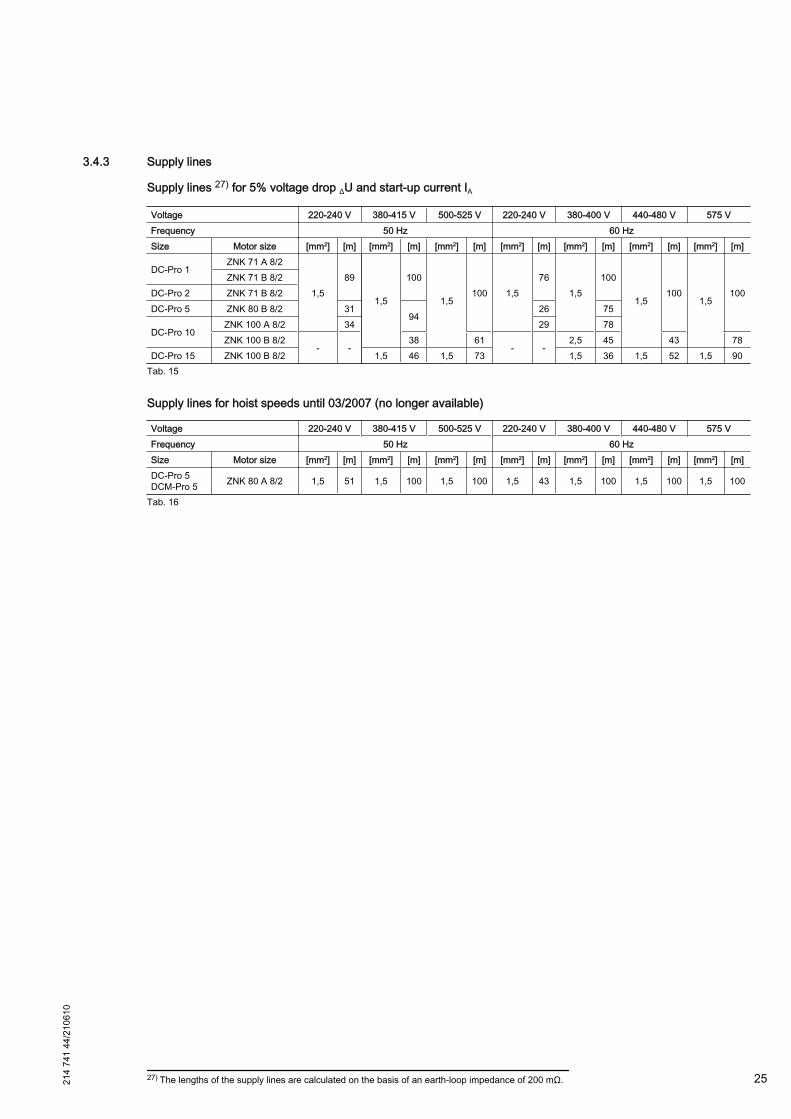
3.4.3 Supply lines
Supply lines 27) for 5% voltage drop ΔU and start-up current IA
Voltage 220-240 V 380-415 V 500-525 V 220-240 V 380-400 V 440-480 V 575 VFrequency 50 Hz 60 HzSize Motor size [mm2] [m] [mm2] [m] [mm2] [m] [mm2] [m] [mm2] [m] [mm2] [m] [mm2] [m]
DC-Pro 1ZNK 71 A 8/2
1,589
1,5
100
1,5100 1,5
761,5
100
1,5100
1,5100
ZNK 71 B 8/2DC-Pro 2 ZNK 71 B 8/2DC-Pro 5 ZNK 80 B 8/2 31
9426 75
DC-Pro 10ZNK 100 A 8/2 34 29 78ZNK 100 B 8/2
- -38 61
- -2,5 45 43 78
DC-Pro 15 ZNK 100 B 8/2 1,5 46 1,5 73 1,5 36 1,5 52 1,5 90Tab. 15
Supply lines for hoist speeds until 03/2007 (no longer available)
Voltage 220-240 V 380-415 V 500-525 V 220-240 V 380-400 V 440-480 V 575 VFrequency 50 Hz 60 HzSize Motor size [mm2] [m] [mm2] [m] [mm2] [m] [mm2] [m] [mm2] [m] [mm2] [m] [mm2] [m]DC-Pro 5DCM-Pro 5 ZNK 80 A 8/2 1,5 51 1,5 100 1,5 100 1,5 43 1,5 100 1,5 100 1,5 100
Tab. 16
27) The lengths of the supply lines are calculated on the basis of an earth-loop impedance of 200 mΩ.214
741
44/2
1061
0
25
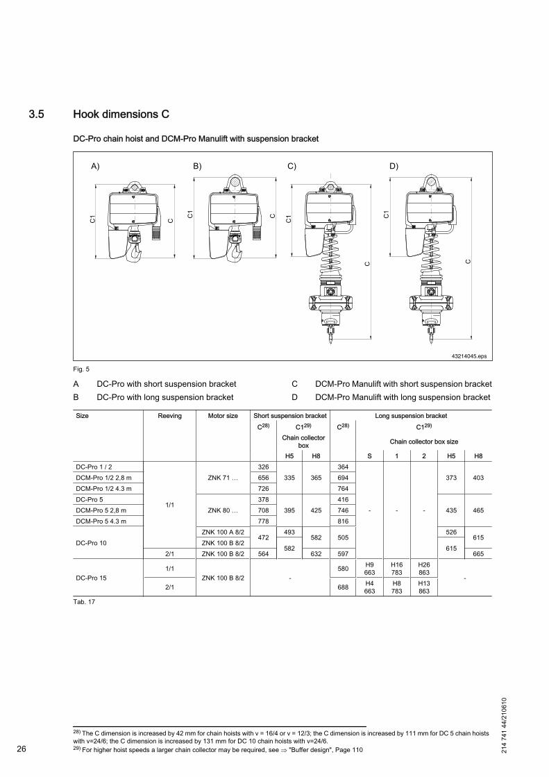
3.5 Hook dimensions C
DC-Pro chain hoist and DCM-Pro Manulift with suspension bracket
43214045.eps
Fig. 5
A DC-Pro with short suspension bracketB DC-Pro with long suspension bracket
C DCM-Pro Manulift with short suspension bracketD DCM-Pro Manulift with long suspension bracket
Size Reeving Motor size Short suspension bracket Long suspension bracket
C28) C129) C28) C129)
Chain collectorbox Chain collector box size
H5 H8 S 1 2 H5 H8DC-Pro 1 / 2
1/1
ZNK 71 …326
335 365364
- - -
373 403DCM-Pro 1/2 2,8 m 656 694DCM-Pro 1/2 4.3 m 726 764DC-Pro 5
ZNK 80 …378
395 425416
435 465DCM-Pro 5 2,8 m 708 746DCM-Pro 5 4.3 m 778 816
DC-Pro 10ZNK 100 A 8/2
472493
582 505526
615ZNK 100 B 8/2
582 6152/1 ZNK 100 B 8/2 564 632 597 665
DC-Pro 151/1
ZNK 100 B 8/2 -580 H9
663H16783
H26863
-2/1 688 H4
663H8783
H13863
Tab. 17
28) The C dimension is increased by 42 mm for chain hoists with v = 16/4 or v = 12/3; the C dimension is increased by 111 mm for DC 5 chain hoistswith v=24/6; the C dimension is increased by 131 mm for DC 10 chain hoists with v=24/6.29) For higher hoist speeds a larger chain collector may be required, see ⇒ "Buffer design", Page 11026 21
4 74
1 44
/210
610
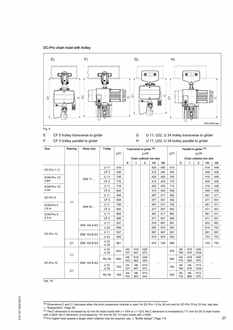
DC-Pro chain hoist with trolley
43214245.eps
Fig. 6
E CF 5 trolley transverse to girderF CF 5 trolley parallel to girder
G U 11, U22, U 34 trolley transverse to girderH U 11, U22, U 34 trolley parallel to girder
Size Reeving Motor size Trolley Transverse to girder 30) Parallel to girder 30)
C31) C132) C31) C132)
Chain collector box size Chain collector box size S 1 2 H5 H8 S 1 2 H5 H8
DC-Pro 1 / 2
1/1
ZNK 71 …
U 11 416
- - -
425 455 410
- - -
419 449CF 5 406 415 445 400 409 439
DCM-Pro 1/22,8m
U 11 746 425 455 740 419 449CF 5 776 415 445 770 409 439
DCM-Pro 1/24.3m
U 11 716 425 455 710 419 449CF 5 844 415 445 838 409 439
DC-Pro 5
ZNK 80 …
U 11 468 487 517 462 481 511CF 5 458 477 507 452 471 501
DCM-Pro 52,8 m
U 11 798 487 517 792 481 511CF 5 846 477 507 840 471 501
DCM-Pro 54.3 m
U 11 868 487 517 862 481 511CF 5 896 477 507 890 471 501
DC-Pro 10
ZNK 100 A 8/2U 11 557 578 667 581 602 691U 22 569 590 679 593 614 703
ZNK 100 B 8/2U 11 557 667 667 581 691 691U 22 569 679 679 593 703 703
2/1 ZNK 100 B 8/2 U 22U 34 661 679 729 685 703 753
DC-Pro 15
1/1
ZNK 100 B 8/2
U 22U 34 644 H9
727H16847
H26972
-
676 H9759
H16879
H261004
-RU 56 660 H9
743H16863
H26943 692 H9
775H16895
H26975
2/1
U 22U 34 752 H4
727H8847
H13972 784 H4
759H8879
H131004
RU 56 768 H4743
H8863
H13943 800 H4
775H8895
H13975
Tab. 18
30) Dimensions C and C1 decrease when the short suspension bracket is used: for DC-Pro 1-5 by 38 mm and for DC-Pro 10 by 33 mm, see also⇒ "Suspension", Page 38.31) The C dimension is increased by 42 mm for chain hoists with v = 16/4 or v = 12/3; the C dimension is increased by 111 mm for DC 5 chain hoistswith v=24/6; the C dimension is increased by 131 mm for DC 10 chain hoists with v=24/6.32) For higher hoist speeds a larger chain collector may be required, see ⇒ "Buffer design", Page 11021
4 74
1 44
/210
610
27
3.6 Noise emission / sound pressure levelThe sound pressure level acc. to DIN 45635 (LpAF) at a distance of 1 m from the chain hoist is:
Type DC-Pro 1 DC-Pro 2 DC-Pro 5 DC-Pro 10 DC-Pro 15Hoist speed up to [m/min] 8 16 12 12 8Sound pressure level [dB (A)] 65+2 65+2 69+2 69+2 69+2
Tab. 19
These noise emission levels were measured under maximum load.
Structural influences such as● transmission of noise via steel structures,● reflection of noise from walls, etc. were not allowed for in the above measurements.
3.7 Transport, packing and storage
3.7.1 Safety instructions
WARNING
Falling partsDuring transport and loading or unloading there is a danger of injury due to parts falling down.– Do not walk under the suspended load. Keep a sufficient safety distance.– Spaciously close off the working area.
WARNING
Transport damageThe chain hoist may be damaged or destroyed by inappropriate transport.Sling lifting and handling equipment only at the correspondingly marked points.
3.7.2 Scope of delivery
If special designs or additional options are ordered or latest technical modifications are incorporated, the actualscope of supply may deviate from the data and information as well as from the illustrations described here. If youhave any questions, please contact the manufacturer.
3.7.3 Transport inspection
● Check the delivery for completeness and transport damage immediately upon receipt.● In the case of transport damage visible from the outside, do not accept the delivery or only under reserve. Note
scope of damage in shipping documents / delivery note of the forwarding company. Bring your claim to attention.● Claim any defects not immediately detected immediately on detecting the defects, since claims for damages may
only be asserted within the valid time for complaints.
3.7.4 Packing
Demag chain hoists, the accessories and the trolleys are shipped in cardboard packing.
If no agreement on the return of the packing material has been made, separate the material according to type andsize and make it available for further use or recycling.
Environmental protection:● Always dispose of packing material in an environmentally sound way and according to the locally applicable
disposal regulations.● If required, a recycling company must be charged with the disposal.
28 214
741
44/2
1061
0

3.7.5 Storage
Keep the equipment and accessories locked and stored only under the following conditions:● Do not store it outdoors.● Store in dry and dust-free places, relative air humidity: max. 60%.● Do not expose it to aggressive media.● Protect it against solar radiation.● Avoid mechanical vibrations.● Storage temperature: -25 to +70 °C.● Avoid strong temperature fluctuations (condensed water).● Oil all blank machine parts (rust protection).● Check the general condition of all parts of the packing at regular intervals. If required, refresh or renew preser‐
vation.● If stored in damp locations, the equipment must be packed tight and protected against corrosion (desiccant).
3.8 Surface protection and paintingAs standard, the chain hoist is supplied with corrosion protection (powder coating/paint finish) in the following colours:
ColoursChain hoist RAL 5009 Azure blueHook assembly RAL 1007 Daffodil yellowLoad hook and suspension bracket RAL 9005 Jet blackTrolley RAL 5009 Azure blue
Tab. 20
Other colours are possible.
214
741
44/2
1061
0
29
3.9 Operating conditions
CAUTION
Operating safety at riskSafe operation is only possible at the specified operating conditions. In the case of other operating conditions pleasecontact the manufacturer ⇒ "Customer service", Page 11
The chain hoist and the trolley can be operated at:
Ambient temperature: -20 °C to +45 °C,Humidity: max. 80 % relative humidity,Height: up to 1000 m above sea level,Type of enclosure: IP55,Electromagnetic compatibility: Resistance to interference in industrial environments,
Interference emissions for residential, commercial and light-industrial environ‐ments.
Tab. 21
Demag chain hoists operating outdoors should be provided with a canopy against the weather. Chain hoists, trolleyand travel drive should be kept under shelter if they are not used for a considerable length of time.
Special operating conditions may be agreed with the manufacturer in individual cases.
Such operating conditions may occur for the following applications, for example:● galvanizing or electroplating plants,● hygiene areas,● low-temperature or hot applications.
On request, suitable optimised equipment and important information for safe, low-wear operation may be suppliedfor these applications.
Under certain ambient conditions, application of cut-off springs is required:● DC1-10 reeving 1/1 hook assembly - Use of switch-off springs (optional)
- for very high mechanical demands on the buffers, e.g. frequent contact with sharp edges,- for extreme ambient conditions (hot atmospheres, foundries, galvanizing plants, etc.).
● DC1-10 reeving 2/1 DK10 aluminium bottom block with external switch-off springs (optional)- for extreme ambient conditions (hot atmospheres, foundries, galvanizing plants, etc.).
● DC 15 hook assembly / standard aluminium bottom block with external switch-off springs.
Reduced duty factor at increased ambient temperature
If the DC chain hoist is operated at ambient temperatures deviating from ⇒ Tab. 21, Page 30, the duty factor mustbe reduced:
Ambient temperature -20 °C to +45 °C > +45 °C to +50 °C > +50 °C to +55 °C > +55 °C to +60 °CChain hoist range Duty factor [%]DC-ProDCM-ProDC-Com 1
20 / 40 15 / 35 15 / 25 10 / 20
DC-Com 2-10 15 / 25 15 / 25 15 / 25 10 / 20Tab. 22
30 214
741
44/2
1061
0
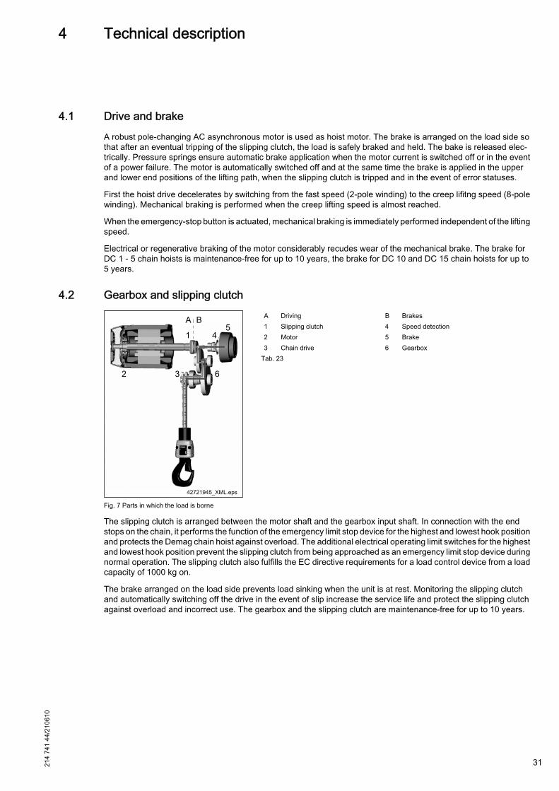
4 Technical description
4.1 Drive and brakeA robust pole-changing AC asynchronous motor is used as hoist motor. The brake is arranged on the load side sothat after an eventual tripping of the slipping clutch, the load is safely braked and held. The bake is released elec‐trically. Pressure springs ensure automatic brake application when the motor current is switched off or in the eventof a power failure. The motor is automatically switched off and at the same time the brake is applied in the upperand lower end positions of the lifting path, when the slipping clutch is tripped and in the event of error statuses.
First the hoist drive decelerates by switching from the fast speed (2-pole winding) to the creep lifitng speed (8-polewinding). Mechanical braking is performed when the creep lifting speed is almost reached.
When the emergency-stop button is actuated, mechanical braking is immediately performed independent of the liftingspeed.
Electrical or regenerative braking of the motor considerably recudes wear of the mechanical brake. The brake forDC 1 - 5 chain hoists is maintenance-free for up to 10 years, the brake for DC 10 and DC 15 chain hoists for up to5 years.
4.2 Gearbox and slipping clutch
Fig. 7 Parts in which the load is borne
A Driving B Brakes1 Slipping clutch 4 Speed detection2 Motor 5 Brake3 Chain drive 6 Gearbox
Tab. 23
The slipping clutch is arranged between the motor shaft and the gearbox input shaft. In connection with the endstops on the chain, it performs the function of the emergency limit stop device for the highest and lowest hook positionand protects the Demag chain hoist against overload. The additional electrical operating limit switches for the highestand lowest hook position prevent the slipping clutch from being approached as an emergency limit stop device duringnormal operation. The slipping clutch also fulfills the EC directive requirements for a load control device from a loadcapacity of 1000 kg on.
The brake arranged on the load side prevents load sinking when the unit is at rest. Monitoring the slipping clutchand automatically switching off the drive in the event of slip increase the service life and protect the slipping clutchagainst overload and incorrect use. The gearbox and the slipping clutch are maintenance-free for up to 10 years.
214
741
44/2
1061
0
31
4.3 Chain driveThe special Demag chain is of high strength ageing-resistant material with a high degree of surface hardening,galvanised with additional surface treatment. The dimension tolerances of this chain have been precisely adaptedto the chain drive. We therefore urgently recommend that the Demag special chain be used to ensure safe operation.The maximum service life of the chain can only be reached, if the specified regular lubrications are appropriatelycarried out. When a chain is replaced, always the entire chain drive is replaced. For this purpose a chain set thatcan easily be replaced is available.
The chain set offers the following benefits:● the optimum duration of service is ensured for the chain;● reliable decision for replacing the individual chain drive components;● reduction in service costs by replacement in one installation process; it is not necessary to dismantle the motor
or the gearbox.
4.4 HousingThe housing of the chain hoist is of strong light-weight die-cast aluminium. The fan cover on the motor, the servicecover and the movable chain collector box are of particularly impact-resistant plastic material.
4.5 Electrical equipment
4.5.1 Control
The chain hoist is provided with a 24-V contactor control system. The contactor control system is supplemented byan electronic system with programmed functions. This electronic system detects the control commands that aretripped by the operator with the control pendant. Permissible control commands generate switching commands forthe contactors to control the hoist motor. The electronic system monitors the control sequence specified by theoperator based on the speed feedback from the drive shaft, the operating limit switch contacts and, if applicable,from the thermal contacts of the motor. In the event of any discrepancies, the chain hoist is automatically broughtto a safe status and warning or error messages are generated. The positively disconnected emergency stop contactof the control pendant immediately opens the circuit for the contactor supply so that the motor is de-energized andthe brake is applied.
As standard, the control system features the following characteristics:● Emergency limit switch for lifting and lowering;● Plug-type connections for control pendant, power supply, motor connection, brake, operating limit switches;● Connection for the E 11 - E 34 trolley control system;● 7-segment display for operating hours, operating status and error messages;● Infrared interface for wireless transmission of service data;● Replaceable contactor with socket for DC-Pro 10 and DC-Pro 15.● Signal transmission in steps with 24 V tri-state signals for controlled DC chain hoists (half-wave evaluation);
For manual control, Demag control pendants are connected via plug-in connectors. For Demag DC chain hoistswithout electric trolleys, the compact DSC optimised for this application is used, the DSE-10C for applications withelectric trolleys.
For integrating the DC chain hoist in existing installations with contactor control, please note the information in thebrochure "DC electrical accessories" ⇒ Tab. 3, Page 7. For controlling pole-changing AC motors (with or withoutbrake) of cross and long travel units the Polu box with integrated contactor control is required, see brochure "Elec‐trical accessories Polu box "⇒ Tab. 3, Page 7.
32 214
741
44/2
1061
0
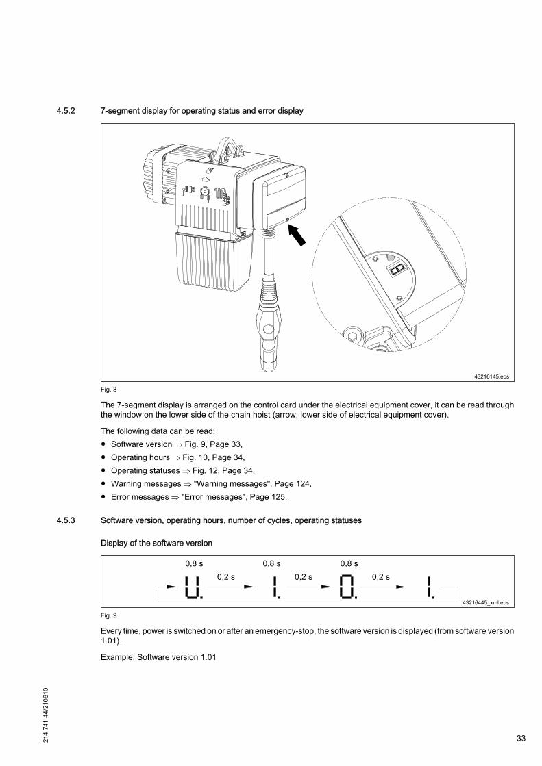
4.5.2 7-segment display for operating status and error display
43216145.eps
Fig. 8
The 7-segment display is arranged on the control card under the electrical equipment cover, it can be read throughthe window on the lower side of the chain hoist (arrow, lower side of electrical equipment cover).
The following data can be read:● Software version ⇒ Fig. 9, Page 33,● Operating hours ⇒ Fig. 10, Page 34,● Operating statuses ⇒ Fig. 12, Page 34,● Warning messages ⇒ "Warning messages", Page 124,● Error messages ⇒ "Error messages", Page 125.
4.5.3 Software version, operating hours, number of cycles, operating statuses
Display of the software version
Fig. 9
Every time, power is switched on or after an emergency-stop, the software version is displayed (from software version1.01).
Example: Software version 1.01
214
741
44/2
1061
0
33

Display of the operating hours
Fig. 10
The display appears after 3 sec. without any lifting motion (example for 123 operating hours)
Display of the number of cycles of the K1 contactor
Fig. 11
Alternatively displayed with the operating hours.
C 5 corresponds to 5 x 100.000 = 500.000 K1 switching cycles
Example: C 15 corresponds to 15 x 100.000 = 1,5 m K1 switching cycles
For preventive maintenance see ⇒ "Service life of the contactor", Page 80
Display of operating statuses
43216046.eps
Fig. 12
No. Function No. Function1 Flashing:
READY FOR OPERA‐TION
2 Emerg. stop pressed
3 LIFTING start-up 4 LOWERING start-up5 LIFTING V1 6 LOWERING V17 LIFTING V2 8 LOWERING V2
Tab. 24
4.6 Central service enclosure
43214444.eps
Fig. 13 34 214
741
44/2
1061
0

All important service work can be carried out at a central point, the service enclosure. The relevant connectors forpower supply, control pendant and travel drive are arranged under the impact-resistant plastic cover. From this point,the chain is also lubricated.
In addition, any control cable length that is not required is kept under the cover.
The plastic cover also provides mechanical protection for the components fitted under it. The functions are describedby pictograms fitted on the outside of the service cover. The service cover of the DC-Pro 15 is made of sheet metalwithout any pictograms.
4.7 Control pendant height adjustment / control cableThe control cable is protected by a flexible, easily bent strain relief hose. Its suspension height can be specificallyadapted to the requirements at the workplace at any time by means of an adjusting mechanism. To do this, it is notnecessary to cut the cable conductors or to shorten the strain relief hose. The control cable that is not required isaccommodated under the service cover. The strain relief hose is fixed at the selected suspension height by meansof a self-locking clamp mechanism. The control pendant can be adjusted to a different suspension height by unlockingthe clamp mechanism.
The strain relief hose for the control pendant consists of an abrasion-resistant fabric hose with flame-protectionimpregnation.
The control cable is reinforced by means of rubber-elastic filler material in the gripping area (0,8 m) of the strainrelief hose.
4.8 Control pendantFor manual cable-connected control of the chain hoist, the DSC control pendants (lifting/lowering) or the DSE-10C(2 to 3 axes) are to be used. Both control pendants feature the same plug-in connection for the control cable. Thecontrol cable and the control pendant are connected by means of a bayonet lock.
The shock and impact-resistant DSC and DSE-10C housings of high quality thermoplastic are resistant to fuels, saltwater, greases, oils and alcaline solutions, type of enclosure IP 65. Strong mineral (e.g. hydrochloric or sulphuric)acids may, however, corrode pendant switch housings. To avoid this, they must be replaced in good time.
The rubber button caps may be subject to premature wear under aggressive operating conditions (contact withcorrosive substances or special chemicals). Replace any damaged button caps in good time.
214
741
44/2
1061
0
35
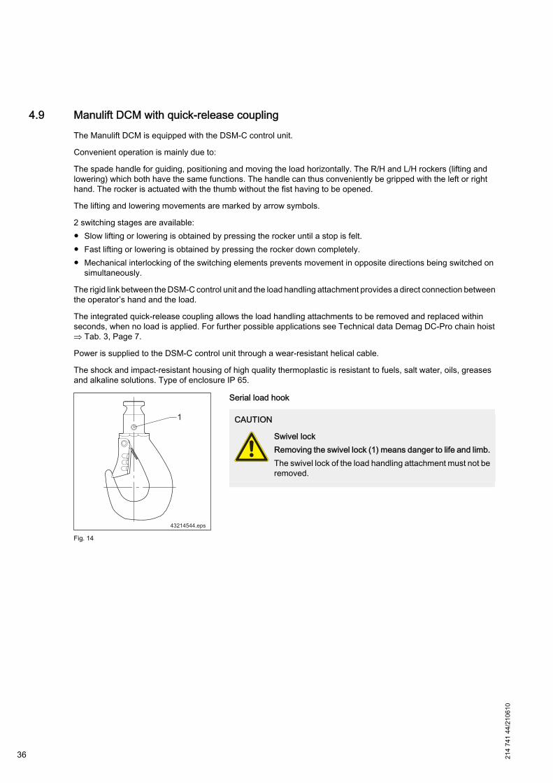
4.9 Manulift DCM with quick-release coupling The Manulift DCM is equipped with the DSM-C control unit.
Convenient operation is mainly due to:
The spade handle for guiding, positioning and moving the load horizontally. The R/H and L/H rockers (lifting andlowering) which both have the same functions. The handle can thus conveniently be gripped with the left or righthand. The rocker is actuated with the thumb without the fist having to be opened.
The lifting and lowering movements are marked by arrow symbols.
2 switching stages are available:● Slow lifting or lowering is obtained by pressing the rocker until a stop is felt.● Fast lifting or lowering is obtained by pressing the rocker down completely.● Mechanical interlocking of the switching elements prevents movement in opposite directions being switched on
simultaneously.
The rigid link between the DSM-C control unit and the load handling attachment provides a direct connection betweenthe operator’s hand and the load.
The integrated quick-release coupling allows the load handling attachments to be removed and replaced withinseconds, when no load is applied. For further possible applications see Technical data Demag DC-Pro chain hoist⇒ Tab. 3, Page 7.
Power is supplied to the DSM-C control unit through a wear-resistant helical cable.
The shock and impact-resistant housing of high quality thermoplastic is resistant to fuels, salt water, oils, greasesand alkaline solutions. Type of enclosure IP 65.
1
43214544.eps
Fig. 14
Serial load hook
CAUTION
Swivel lockRemoving the swivel lock (1) means danger to life and limb.The swivel lock of the load handling attachment must not beremoved.
36 214
741
44/2
1061
0
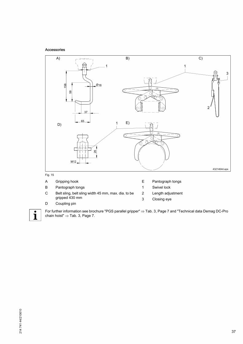
Accessories
Fig. 15
A Gripping hookB Pantograph tongsC Belt sling, belt sling width 45 mm, max. dia. to be
gripped 430 mmD Coupling pin
E Pantograph tongs1 Swivel lock2 Length adjustment3 Closing eye
For further information see brochure "PGS parallel gripper" ⇒ Tab. 3, Page 7 and "Technical data Demag DC-Prochain hoist" ⇒ Tab. 3, Page 7.
214
741
44/2
1061
0
37
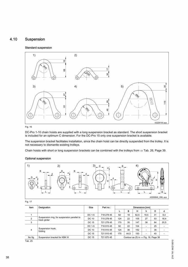
4.10 Suspension
Standard suspension
Fig. 16
DC-Pro 1-10 chain hoists are supplied with a long suspension bracket as standard. The short suspension bracketis included for an optimum C dimension. For the DC-Pro 15 only one suspension bracket is available.
The suspension bracket facilitates installation, since the chain hoist can be directly suspended from the trolley. It isnot necessary to dismantle existing trolleys.
Chain hoists with short or long suspension brackets can be combined with the trolleys from ⇒ Tab. 26, Page 39.
Optional suspension
Fig. 17
Item Designation Size Part no.: Dimensions [mm]L B H h D d
1Suspension ring, for suspension parallel totrack girder
DC 1-5 718 278 45 92 18 62,5 19,5 31 8,42 DC 10 715 278 45 124 22 105 27 53 18,43 DC 15 721 278 45 170 35 147 38 84 20,5
4 Suspension hook,folding
DC 1-5 718 910 45 92 22 104 - 25 -DC 10 715 910 45 124 36 152 - 36 -DC 15 721 910 45 170 44,5 193 - 40 -
No fig. Suspension bracket for KBK III DC 15 721 870 45 Contour as (5) in ⇒ Fig. 16, Page 38Tab. 25
38 214
741
44/2
1061
0
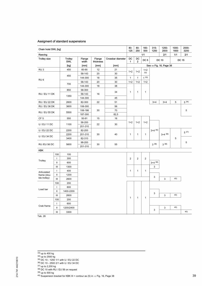
Assigment of standard suspensions
Chain hoist SWL [kg] 80-125
80-250
160-500
315-1250
1250-2500
1000-1600
2000-3200
Reeving 1/1 2/1 1/1 2/1Trolley size Trolley
SWLFlangewidth
Flangethickness
Crossbar diameter DC1
DC2 DC 5 DC 10 DC 15
[kg] [mm] [mm] [mm] See ⇒ Fig. 16, Page 38RU 3 450 60-90 12 21
1+2 1+2 1+233)
RU 6
45058-143 20 30
144-300 18 35 1 1 1 33)
70058-143 20 30 1+2 1+2 1+2
144-300 18 38
1 1 1RU / EU 11 DK
850 58-30016
341350
58-143144-300 45
RU / EU 22 DK 2600 82-300 22 51 3+4 3+4 5 5 34)
RU / EU 36 DK 3600 106-30030
56 5
RU / EU 55 DK 5500106-186 70187-300 82,5
CF 5 550 50-91 15 161+2 1+2 1+2
U / EU 11 DC 110058-200
22 30
3+4 35)
201-310U / EU 22 DC 2200 82-200
30 40 1 1 1 3+4 36)
5
5 37)
U / EU 34 DC2200 201-3103400 82-310
5RU /EU 56 DC 5600
98-20030 55 3 38) 3 38)
201-310KBK
Trolley
100 100
2 2 2
I 300II 600 3+4 39)
III 13001 1 1
3
Articulatedframe (dou‐ble trolley)
I 400 II 1200
3III 2600 3 40)
Load bar
100 200
1 1 1
I 600II 1400-2200
3III 2600 3 40)
Crab frame
100 200
I 600II 1200/2400
33 40)
III 3300 40)
Tab. 26
33) up to 400 kg34) up to 2500 kg35) DC 10 - 1250 1/1 with U / EU 22 DC36) DC 10 - 2500 2/1 with U / EU 34 DC37) up to 2,200 kg38) DC 10 with RU / EU 56 on request39) up to 500 kg40) Suspension bracket for KBK III = contour as (5) in ⇒ Fig. 16, Page 3821
4 74
1 44
/210
610
39

4.11 Trolley
Fig. 18
WARNING
OverloadThere is danger to life and limb due to a possible excessive load of the trolley.The load capacity of Demag chain hoists must not exceed the load capacity of the trolley.
I beam track
The use of I beams with parallel or sloping flanges according to DIN 1025 as tracks is possible.
The curve radii should be as large as possible in order to ensure good travel characteristics.
I beam tracks should be bent with the utmost care in order to obtain a clean, regular curve.
Hoist travel on I beam tracks must in no way be obstructed by protruding suspension bolts, screw heads, clampingplates, joint flanges, etc.
Resilient buffers should be mounted at travel wheel axle level at the ends of tracks in order to prevent the trolleyfrom derailing (e.g. Demag clamp-fitted buffers).
For further information on the trolleys and the power supply, see ⇒ Tab. 3, Page 7.
Curve radii for trolleys
The specified curve radii apply for normal applications. Contact the manufacturer or his representative for frequentcurve travel operation (e.g. automatic installations).
Curve radii in mmTrolley size SWL Runway girder Travel wheel
materialPush travel Electric travel
Flange width41) Rmin Flange width41) Rmin
[kg] [mm] [mm] [mm] [mm] CF 5 550 50-91 800 - - Plastic
U 11 DC EU 11 DC 1100 58-310 1000 58-310 2000 Plastic42)
U 22 DC EU 22 DC 2200 82-2002000
82-2003000
Spheroidalgraphite cast iron
U 34 DC EU 34 DC2200 201-310 201-310
Spheroidalgraphite cast iron3400 82-310 82-310
RU 56 DC EU 56 DC 5600 98-310 2000 43) 98-310 2500 43)
Tab. 27
41) Max. flange width 500 mm (except CF 5)42) Steel travel rollers optional43) From flange width 106 mm40 21
4 74
1 44
/210
610
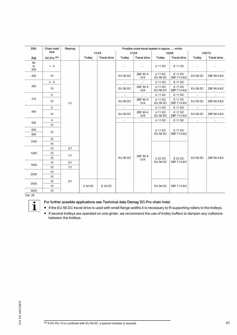
SWL Chain hoistsize
Reeving Possible cross-travel speeds in approx. ... m/minV14/3 V12/4 V24/6 V40/10
[kg] DC-Pro 44) Trolley Travel drive Trolley Travel drive Trolley Travel drive Trolley Travel drive
80to
2001 - 5
1/1
- -
- - U 11 DC E 11 DC - -
200 10 EU 56 DC ZBF 80 A12/4
U 11 DCEU 56 DC
E 11 DCZBF 71 A 8/2 EU 56 DC ZBF 80 A 8/2
2502 - 5 - - U 11 DC E 11 DC - -
10 EU 56 DC ZBF 80 A12/4
U 11 DCEU 56 DC
E 11 DCZBF 71 A 8/2 EU 56 DC ZBF 80 A 8/2
3155 - - U 11 DC E 11 DC - -
10 EU 56 DC ZBF 80 A12/4
U 11 DCEU 56 DC
E 11 DCZBF 71 A 8/2 EU 56 DC ZBF 80 A 8/2
4005 - - U 11 DC E 11 DC - -
10 EU 56 DC ZBF 80 A12/4
U 11 DCEU 56 DC
E 11 DCZBF 71 A 8/2 EU 56 DC ZBF 80 A 8/2
5005 - - U 11 DC E 11 DC - -
10
EU 56 DC ZBF 80 A12/4
U 11 DCEU 56 DC
E 11 DCZBF 71 A 8/2
EU 56 DC ZBF 80 A 8/2
63010
800
10001015
U 22 DCEU 56 DC
E 22 DCZBF 71 A 8/2
125010 2/110
1/115
160010 2/115 1/1
200010
2/115
250010
U 34 DC E 34 DC EU 56 DC ZBF 71 A 8/2153200 15
Tab. 28
For further possible applications see Technical data Demag DC-Pro chain hoist.● If the EU 56 DC travel drive is used with small flange widths it is necessary to fit supporting rollers to the trolleys.● If several trolleys are operated on one girder, we recommend the use of trolley buffers to dampen any collisions
between the trolleys.
44) If DC-Pro 10 is combined with EU 56 DC, a special crossbar is required.214
741
44/2
1061
0
41
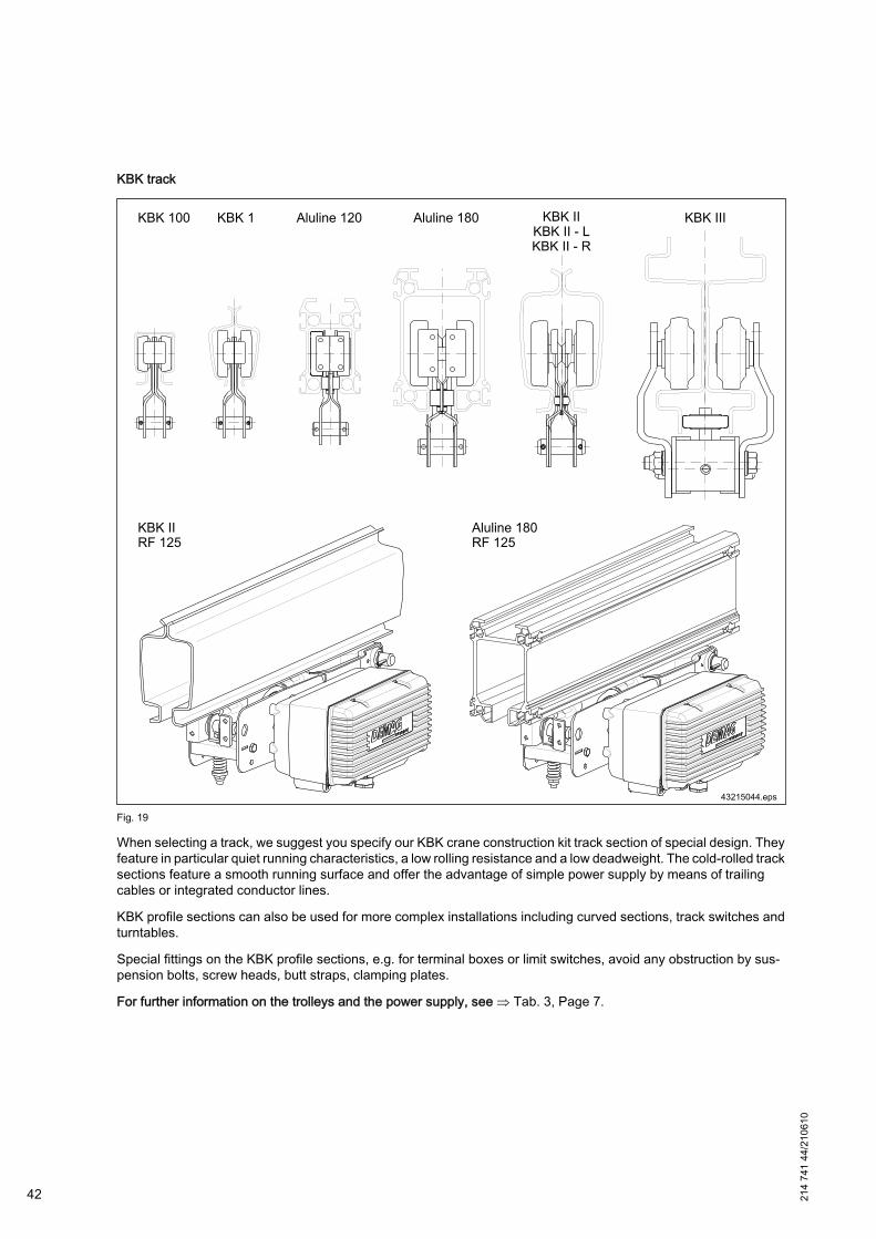
KBK track
Fig. 19
When selecting a track, we suggest you specify our KBK crane construction kit track section of special design. Theyfeature in particular quiet running characteristics, a low rolling resistance and a low deadweight. The cold-rolled tracksections feature a smooth running surface and offer the advantage of simple power supply by means of trailingcables or integrated conductor lines.
KBK profile sections can also be used for more complex installations including curved sections, track switches andturntables.
Special fittings on the KBK profile sections, e.g. for terminal boxes or limit switches, avoid any obstruction by sus‐pension bolts, screw heads, butt straps, clamping plates.
For further information on the trolleys and the power supply, see ⇒ Tab. 3, Page 7.
42 214
741
44/2
1061
0

5 Assembly
5.1 GeneralThese assembly instructions enable the owner to fit and/or refit or replace the DC-Pro himself. The owner mustappoint a coordinator who is authorized to issue instructions before assembly work commences.
Despite detailed information, mistakes when assembling by the customer cannot be excluded. For this reason, werecommend this work be carried out by our trained specialists or by persons authorized by us.
The wiring of the Demag chain hoist complies in all respects with current DIN VDE and accident prevention regu‐lations.
Unauthorized intervention and modifications result in eliminating compliance with these regulations.
DANGER
Live componentsDanger to life and limb.It must be possible to switch off powerfeed by means of a device for disconnecting the powerfeed (e.g. mainsconnection or isolator switch with padlock).
The chain hoists are supplied with power from an AC power network. The voltage and frequency of the AC powernetwork must match the data specified on the rating plate of the chain hoist.
5.2 Safety instructions for assembly
DANGER
Inappropriate assemblyDanger to life and limb.Inappropriate assembly may result in serious personal injury and / or material damage. Therefore only authorizedand trained personnel who is familiar with the operating principle of the machine may carry out this work in com‐pliance with all safety regulations.– Before starting work ensure that sufficient working clearance is available.– Secure working and danger zone.– When using a working platform for assembly, only systems designed for passenger transport should be used
that provide for a stable position and work without any risk.– Only suitable, tested and calibrated tools and accessories may be used for assembly or disassembly work.– Wear protective equipment!– Caution on open sharp-edged parts! Risk of injury!– Ensure order and cleanliness at the workplace. Machine parts or fittings that are not required must be stored
so that they cannot fall down.– Appropriately fit component parts. Tighten screws with the prescribed tightening torque. Inappropriately fixed
component parts may fall down and result in severe injuries.– Welding work may only be carried out by persons having a special qualification. The requirements of DIN
regarding welding work must be complied with. The electrode holder and earth must be connected to the sameassembly when welding work is carried out. Otherwise serious damage may be caused to the hoist.
– Customer-specific regulations must be observed.
DANGER
Live componentsDanger to life and limb.Work on electrical equipment may only be carried out by qualified specialist personnel(⇒ "Definition of personnel",Page 10 ) in compliance with the safety instructions.
214
741
44/2
1061
0
43
Before starting work, the electrical supply must be switched off. The mains connection or isolator switch must besecured against unauthorized or accidental reconnection by means of a padlock.
Mechanical safetyAll bolted connections must be correctly tightened.Self-locking nuts must not be replaced by other types of nut. Self-locking nuts must be replaced when they havebeen tightened and untightened five times. The clamping torque of a self-locking nut must not be lower than thescrew-off torque specified by EN ISO 2320.Only by tightening to the specific tightening torque can a sufficiently secure connection be guaranteed.Bolted connections must not be lubricated as otherwise the specified tightening torque values will be too high.Check that pin connections are properly secured.All assembly work must be completed in accordance with the operating instructions and the hoist chain must begreased. Operation with defective or damaged chains results in a high risk of accident for persons and the chainhoist and is therefore prohibited.Any change or modification which prejudices safety must immediately be reported to the nearest person responsible.Repairs may only be carried out by experienced technicians.Ensure that all suspension fittings are freely accessible for checks and inspections or that free access can be pro‐vided.The control device (e.g. control pendant) must be marked in such a way that the direction of movement is clear anddistinct. The arrow symbol on the control elements must correspond to the direction of movement.
Electrical safetyThe chain hoist operating instructions must be referred to when Demag chain hoists are used.These operating instructions only contain standard circuit diagrams. Depending on the type of chain hoist an order-specific circuit diagram may apply.
Protective earth conductorThe protective earth conductor in insulated leads and cables must be coloured green and yellow along its entirelength.The protective earth conductor must not be connected to mounting bolts or screws.Earth junctions and connections must be protected against self-loosening (e.g. by using serrated lock washers toDIN 6798). It must be possible to disconnect each individual connection.Protective earth conductors must not carry any current in operationThe same number of protective earth connection points must be provided as electrical power infeed and outfeedpoints.Continuity of the PE conductor connection must be checked.
Mains connection switchA mains connection switch must always be provided for the main power supply line of the machine. This switch mustbe arranged to disconnect all poles of the DC-Pro chain hoist from the mains supply.Ensure that the switch is installed in an easily accessible position near your machine and clearly marked.
Isolator switchIf two or more hoists are fed from a common main supply line, each one should be provided with an isolator switch.This makes it possible to carry out maintenance work on individual hoists, without affecting operation of the rest ofthe system.
Power supply systemThe power supply line / cable to be used depends on the motor size, see section "Hoist motor data".
44 214
741
44/2
1061
0

5.3 Tightening torques DC-Pro chain hoistTightening torques [Nm] DC-Pro 1 DC-Pro 2 DC-Pro 5 DC-Pro 10 DC-Pro 15Reeving 1/1 1/1 2/1 1/1 2/1Motor 9,5 25,0Fan cover 4,0Gearbox cover 5,5 -Gearbox housing 2-piece - 25Gearbox screw plug - 15Gearbox vent valve - 15Brake 5,5Operating limit switches 1,5 3,0Control set 3,0Electrical equipment cover 9,5Service cover 5,5 7,5 25Limit stop 4,0 4,3Anchorage halves - 10,5 - 25Guide plate 5,5 25Hook assembly 6,8 11,5 25,0 - 27,5 -Bottom block with external switch-off springs
-
55,0 - 55,0
Bottom block with internal switch-offsprings
Bottom blockhalves 52,0 -
Guide halves 5,5 -Screw for chain retainer halves (Manulift) 5 - 6 -Control cable lock 11,0
Tab. 29
CAUTION
Loose connectionsLoose connections mean danger for life and limb or risk of machine damage.Metal nuts featuring a locking element (self-locking nuts) are mainly used for Demag chain hoists.– Self-locking nuts must not be replaced by other types of nut.
5.4 Assembly procedure1. Unpack and dispose of packing material in an environmentally compatible way ⇒ "Transport, packing and
storage", Page 28.
2. Check for completeness ⇒ "Transport inspection", Page 28.
3. Connect control pendant, as required ⇒ "Connecting the control pendant", Page 46.
4. Which suspension bracket is suitable for suspension? ⇒ "Suspending the chain hoist", Page 48.
5. Adjust control pendant height ⇒ "Height adjustment of the control pendant", Page 51.
6. Connect to power supply ⇒ "Line connection", Page 54.
7. Adjust lower hook position as required ⇒ "Setting the lower hook position", Page 67.
8. Carry out inspections prior to putting the hoist into service for the first time ⇒ "Inspections prior to putting intoservice for the first time", Page 69.
9. The unit is ready for operation. ⇒ "Operation", Page 70.
214
741
44/2
1061
0
45
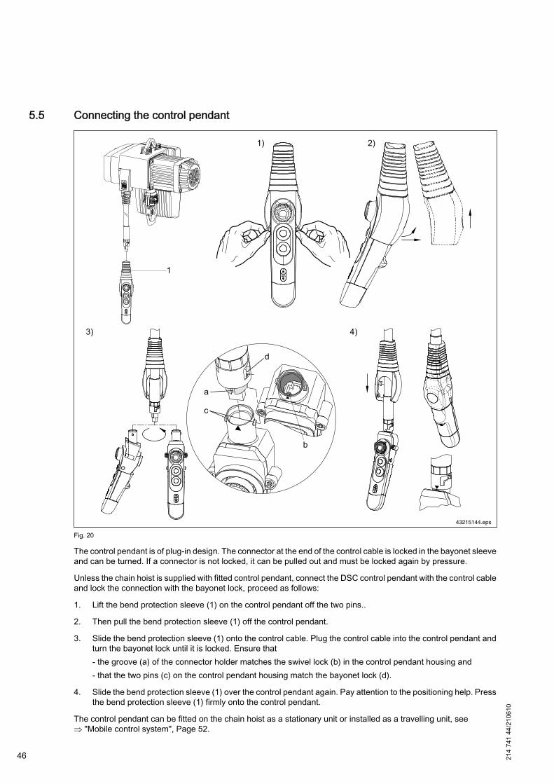
5.5 Connecting the control pendant
43215144.eps
Fig. 20
The control pendant is of plug-in design. The connector at the end of the control cable is locked in the bayonet sleeveand can be turned. If a connector is not locked, it can be pulled out and must be locked again by pressure.
Unless the chain hoist is supplied with fitted control pendant, connect the DSC control pendant with the control cableand lock the connection with the bayonet lock, proceed as follows:
1. Lift the bend protection sleeve (1) on the control pendant off the two pins..
2. Then pull the bend protection sleeve (1) off the control pendant.
3. Slide the bend protection sleeve (1) onto the control cable. Plug the control cable into the control pendant andturn the bayonet lock until it is locked. Ensure that- the groove (a) of the connector holder matches the swivel lock (b) in the control pendant housing and- that the two pins (c) on the control pendant housing match the bayonet lock (d).
4. Slide the bend protection sleeve (1) over the control pendant again. Pay attention to the positioning help. Pressthe bend protection sleeve (1) firmly onto the control pendant.
The control pendant can be fitted on the chain hoist as a stationary unit or installed as a travelling unit, see⇒ "Mobile control system", Page 52.
46 214
741
44/2
1061
0

214
741
44/2
1061
0
47
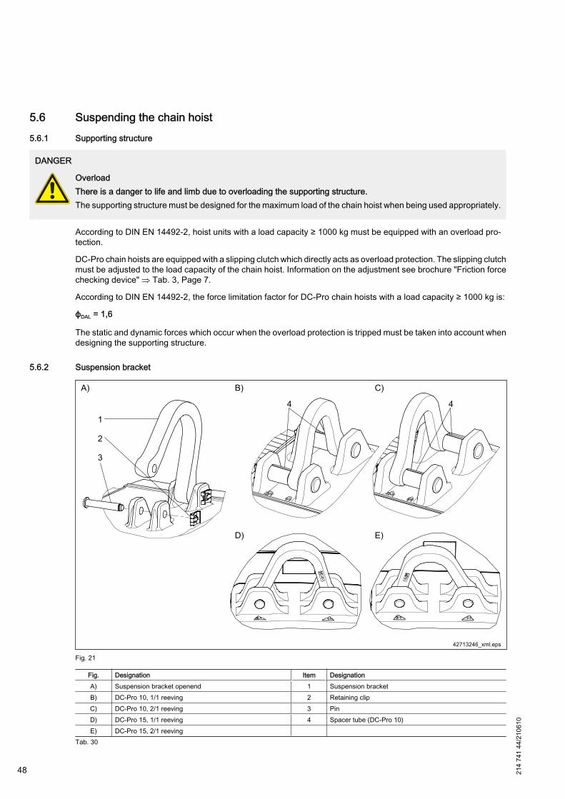
5.6 Suspending the chain hoist5.6.1 Supporting structure
DANGER
OverloadThere is a danger to life and limb due to overloading the supporting structure.The supporting structure must be designed for the maximum load of the chain hoist when being used appropriately.
According to DIN EN 14492-2, hoist units with a load capacity ≥ 1000 kg must be equipped with an overload pro‐tection.
DC-Pro chain hoists are equipped with a slipping clutch which directly acts as overload protection. The slipping clutchmust be adjusted to the load capacity of the chain hoist. Information on the adjustment see brochure "Friction forcechecking device" ⇒ Tab. 3, Page 7.
According to DIN EN 14492-2, the force limitation factor for DC-Pro chain hoists with a load capacity ≥ 1000 kg is:
ϕDAL = 1,6
The static and dynamic forces which occur when the overload protection is tripped must be taken into account whendesigning the supporting structure.
5.6.2 Suspension bracket
Fig. 21
Fig. Designation Item DesignationA) Suspension bracket openend 1 Suspension bracketB) DC-Pro 10, 1/1 reeving 2 Retaining clipC) DC-Pro 10, 2/1 reeving 3 PinD) DC-Pro 15, 1/1 reeving 4 Spacer tube (DC-Pro 10)E) DC-Pro 15, 2/1 reeving
Tab. 30
48 214
741
44/2
1061
0
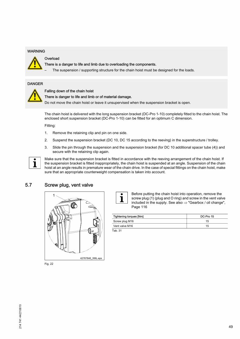
WARNING
OverloadThere is a danger to life and limb due to overloading the components.– The suspension / supporting structure for the chain hoist must be designed for the loads.
DANGER
Falling down of the chain hoistThere is danger to life and limb or of material damage.Do not move the chain hoist or leave it unsupervised when the suspension bracket is open.
The chain hoist is delivered with the long suspension bracket (DC-Pro 1-10) completely fitted to the chain hoist. Theenclosed short suspension bracket (DC-Pro 1-10) can be fitted for an optimum C dimension.
Fitting:
1. Remove the retaining clip and pin on one side.
2. Suspend the suspension bracket (DC 10, DC 15 according to the reeving) in the superstructure / trolley.
3. Slide the pin through the suspension and the suspension bracket (for DC 10 additional spacer tube (4)) andsecure with the retaining clip again.
Make sure that the suspension bracket is fitted in accordance with the reeving arrangement of the chain hoist. Ifthe suspension bracket is fitted inappropriately, the chain hoist is suspended at an angle. Suspension of the chainhoist at an angle results in premature wear of the chain drive. In the case of special fittings on the chain hoist, makesure that an appropriate counterweight compensation is taken into account.
5.7 Screw plug, vent valve
Fig. 22
Before putting the chain hoist into operation, remove thescrew plug (1) (plug and O ring) and screw in the vent valveincluded in the supply. See also ⇒ "Gearbox / oil change",Page 116
Tightening torques [Nm] DC-Pro 15Screw plug M16 15Vent valve M16 15
Tab. 31
214
741
44/2
1061
0
49
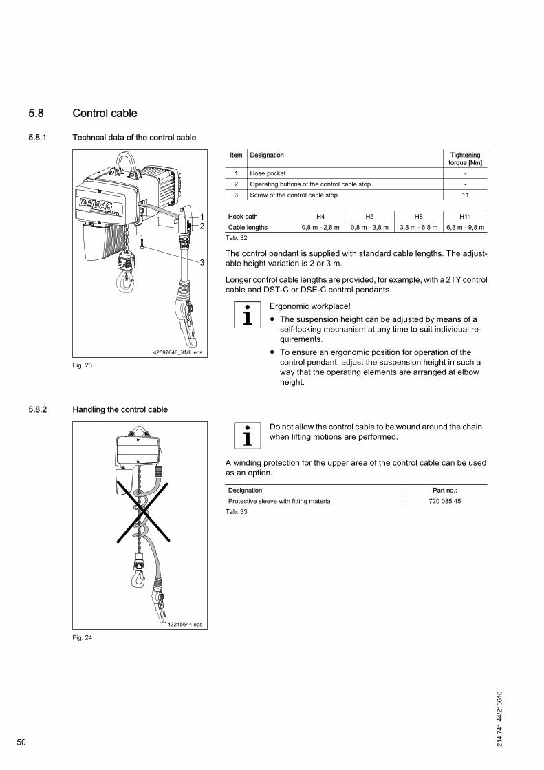
5.8 Control cable
5.8.1 Techncal data of the control cable
42597646_XML.eps
Fig. 23
Item Designation Tighteningtorque [Nm]
1 Hose pocket -2 Operating buttons of the control cable stop -3 Screw of the control cable stop 11
Hook path H4 H5 H8 H11Cable lengths 0,8 m - 2,8 m 0,8 m - 3,8 m 3,8 m - 6,8 m 6,8 m - 9,8 m
Tab. 32
The control pendant is supplied with standard cable lengths. The adjust‐able height variation is 2 or 3 m.
Longer control cable lengths are provided, for example, with a 2TY controlcable and DST-C or DSE-C control pendants.
Ergonomic workplace!● The suspension height can be adjusted by means of a
self-locking mechanism at any time to suit individual re‐quirements.
● To ensure an ergonomic position for operation of thecontrol pendant, adjust the suspension height in such away that the operating elements are arranged at elbowheight.
5.8.2 Handling the control cable
Fig. 24
Do not allow the control cable to be wound around the chainwhen lifting motions are performed.
A winding protection for the upper area of the control cable can be usedas an option.
Designation Part no.:Protective sleeve with fitting material 720 085 45
Tab. 33
50 214
741
44/2
1061
0
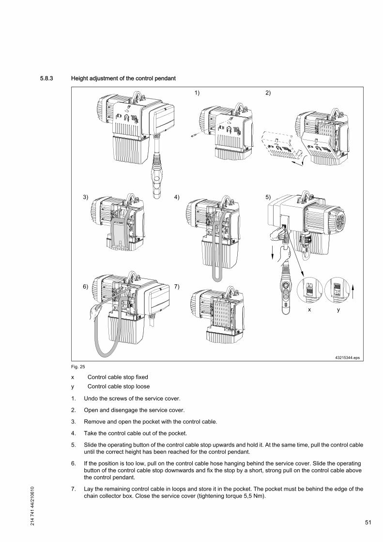
5.8.3 Height adjustment of the control pendant
Fig. 25
x Control cable stop fixedy Control cable stop loose
1. Undo the screws of the service cover.
2. Open and disengage the service cover.
3. Remove and open the pocket with the control cable.
4. Take the control cable out of the pocket.
5. Slide the operating button of the control cable stop upwards and hold it. At the same time, pull the control cableuntil the correct height has been reached for the control pendant.
6. If the position is too low, pull on the control cable hose hanging behind the service cover. Slide the operatingbutton of the control cable stop downwards and fix the stop by a short, strong pull on the control cable abovethe control pendant.
7. Lay the remaining control cable in loops and store it in the pocket. The pocket must be behind the edge of thechain collector box. Close the service cover (tightening torque 5,5 Nm).
214
741
44/2
1061
0
51

5.8.4 Mobile control system
Fig. 26
Component partsItem Designation comprising Part no.:
1 Flat cable 11-pole + PE 720 139 45
2 Connector enclosure cpl.
Socket enclosure
720 187 45Fitting framePin insert VC-AMS8Flat cable union
3 Connector adapter cpl.
Bayonet lock
720 087 45Bush enclosure VC-MP-1-R-M25Bush frame VC-TR1/2MSocket insert VC-TFS8
4 Cable collector 720 065 455 DSE10-C control pendant 773 352 456 Control cable lock -
Tab. 34
For use of the cable collector, the height-adjustable standard control ca‐bles H4, H5, H8, H11 are used.
Fig. 27
X40 plug connector connections
SignalCon‐duc‐tor
PINCon‐duc‐tor
Signal
- - B4 B8 11 Reference potential (24 V)PE PE B3 B7 - -- - B2 B6 - -
Special 2 (horn) 8 B1 B5 10 RightLeft 4 A4 A8 7 Lowering
Lifting 3 A3 A7 9 Control voltage(24 V, STS)
Emergency stop 2 A2 A6 6 BackwardForward 1 A1 A5 5 Special 1 (F1/F2)
Tab. 35
52 214
741
44/2
1061
0

214
741
44/2
1061
0
53
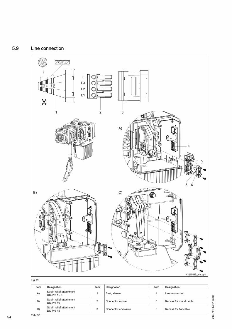
5.9 Line connection
Fig. 28
Item Designation Item Designation Item Designation
A) Strain relief attachmentDC-Pro 1 - 5 1 Seal, sleeve 4 Line connection
B) Strain relief attachmentDC-Pro 10 2 Connector 4-pole 5 Recess for round cable
C) Strain relief attachmentDC-Pro 15 3 Connector enclosure 6 Recess for flat cable
Tab. 36 54 214
741
44/2
1061
0
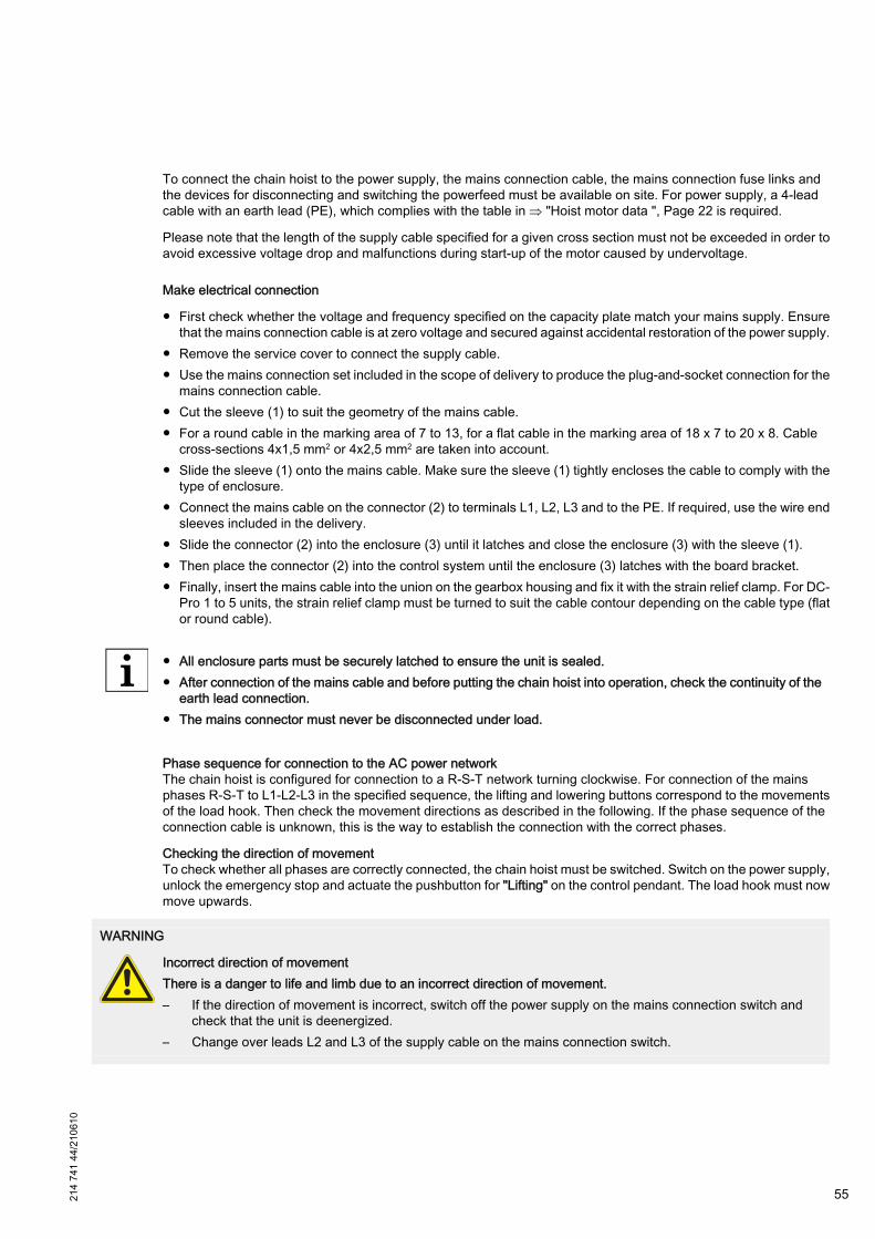
To connect the chain hoist to the power supply, the mains connection cable, the mains connection fuse links andthe devices for disconnecting and switching the powerfeed must be available on site. For power supply, a 4-leadcable with an earth lead (PE), which complies with the table in ⇒ "Hoist motor data ", Page 22 is required.
Please note that the length of the supply cable specified for a given cross section must not be exceeded in order toavoid excessive voltage drop and malfunctions during start-up of the motor caused by undervoltage.
Make electrical connection
● First check whether the voltage and frequency specified on the capacity plate match your mains supply. Ensurethat the mains connection cable is at zero voltage and secured against accidental restoration of the power supply.
● Remove the service cover to connect the supply cable.● Use the mains connection set included in the scope of delivery to produce the plug-and-socket connection for the
mains connection cable.● Cut the sleeve (1) to suit the geometry of the mains cable.● For a round cable in the marking area of 7 to 13, for a flat cable in the marking area of 18 x 7 to 20 x 8. Cable
cross-sections 4x1,5 mm2 or 4x2,5 mm2 are taken into account.● Slide the sleeve (1) onto the mains cable. Make sure the sleeve (1) tightly encloses the cable to comply with the
type of enclosure.● Connect the mains cable on the connector (2) to terminals L1, L2, L3 and to the PE. If required, use the wire end
sleeves included in the delivery.● Slide the connector (2) into the enclosure (3) until it latches and close the enclosure (3) with the sleeve (1).● Then place the connector (2) into the control system until the enclosure (3) latches with the board bracket.● Finally, insert the mains cable into the union on the gearbox housing and fix it with the strain relief clamp. For DC-
Pro 1 to 5 units, the strain relief clamp must be turned to suit the cable contour depending on the cable type (flator round cable).
● All enclosure parts must be securely latched to ensure the unit is sealed.● After connection of the mains cable and before putting the chain hoist into operation, check the continuity of the
earth lead connection.● The mains connector must never be disconnected under load.
Phase sequence for connection to the AC power networkThe chain hoist is configured for connection to a R-S-T network turning clockwise. For connection of the mainsphases R-S-T to L1-L2-L3 in the specified sequence, the lifting and lowering buttons correspond to the movementsof the load hook. Then check the movement directions as described in the following. If the phase sequence of theconnection cable is unknown, this is the way to establish the connection with the correct phases.
Checking the direction of movementTo check whether all phases are correctly connected, the chain hoist must be switched. Switch on the power supply,unlock the emergency stop and actuate the pushbutton for "Lifting" on the control pendant. The load hook must nowmove upwards.
WARNING
Incorrect direction of movementThere is a danger to life and limb due to an incorrect direction of movement.– If the direction of movement is incorrect, switch off the power supply on the mains connection switch and
check that the unit is deenergized.– Change over leads L2 and L3 of the supply cable on the mains connection switch.
214
741
44/2
1061
0
55
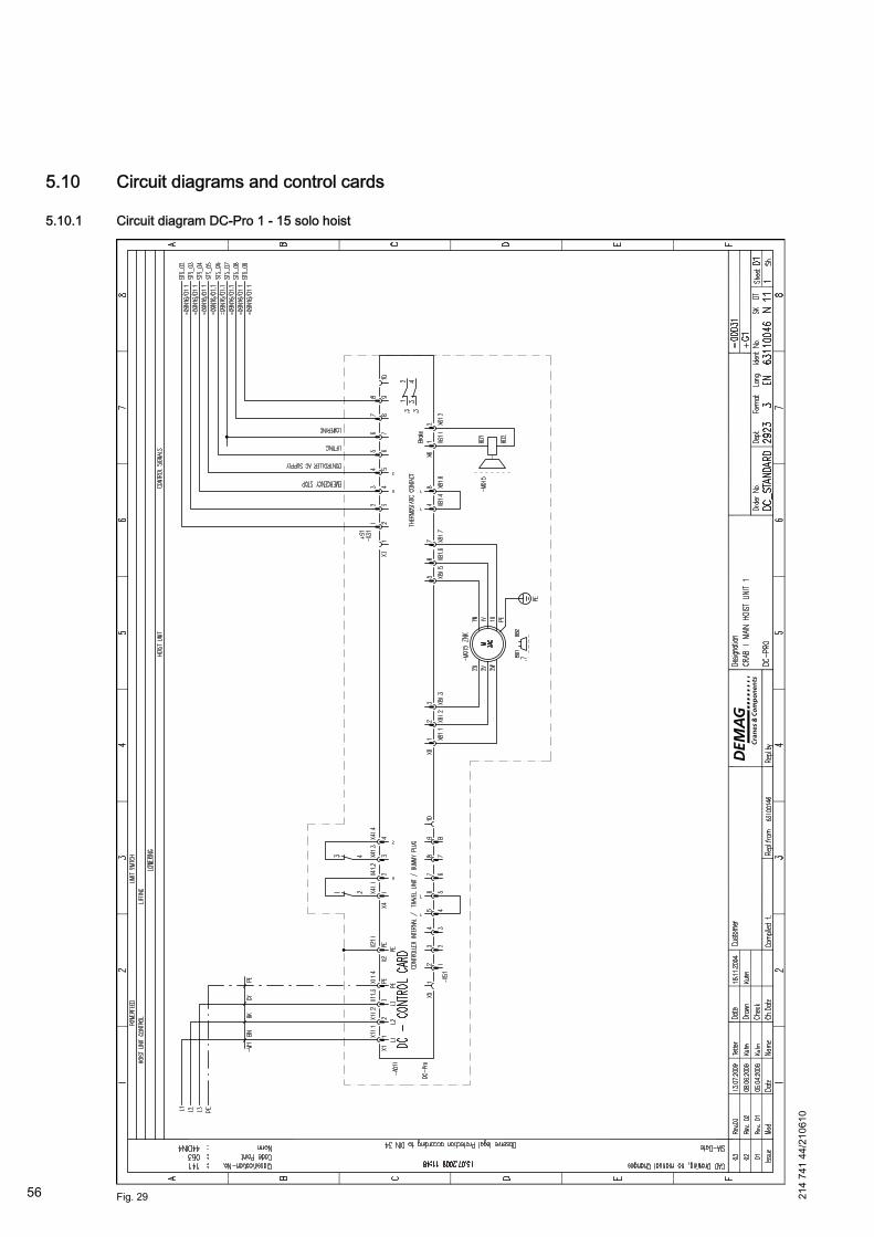
5.10 Circuit diagrams and control cards
5.10.1 Circuit diagram DC-Pro 1 - 15 solo hoist
Fig. 29 56 214
741
44/2
1061
0

Fig. 30
214
741
44/2
1061
0
57
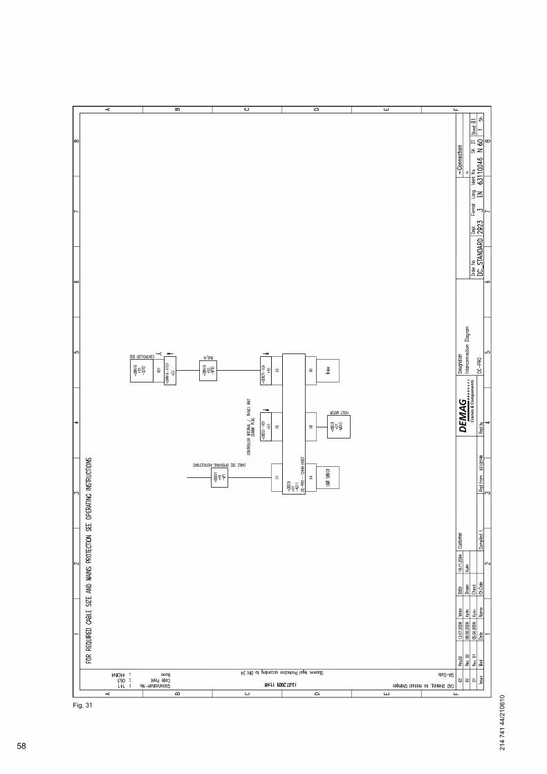
Fig. 31
58 214
741
44/2
1061
0
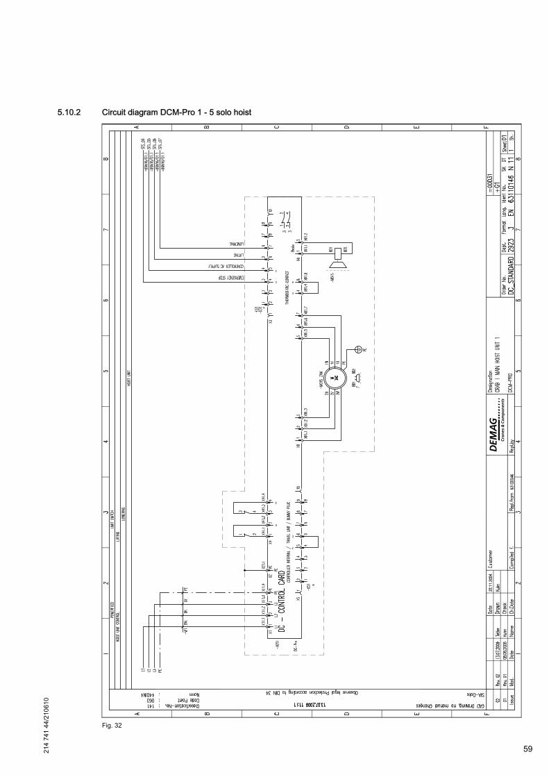
5.10.2 Circuit diagram DCM-Pro 1 - 5 solo hoist
Fig. 32
214
741
44/2
1061
0
59
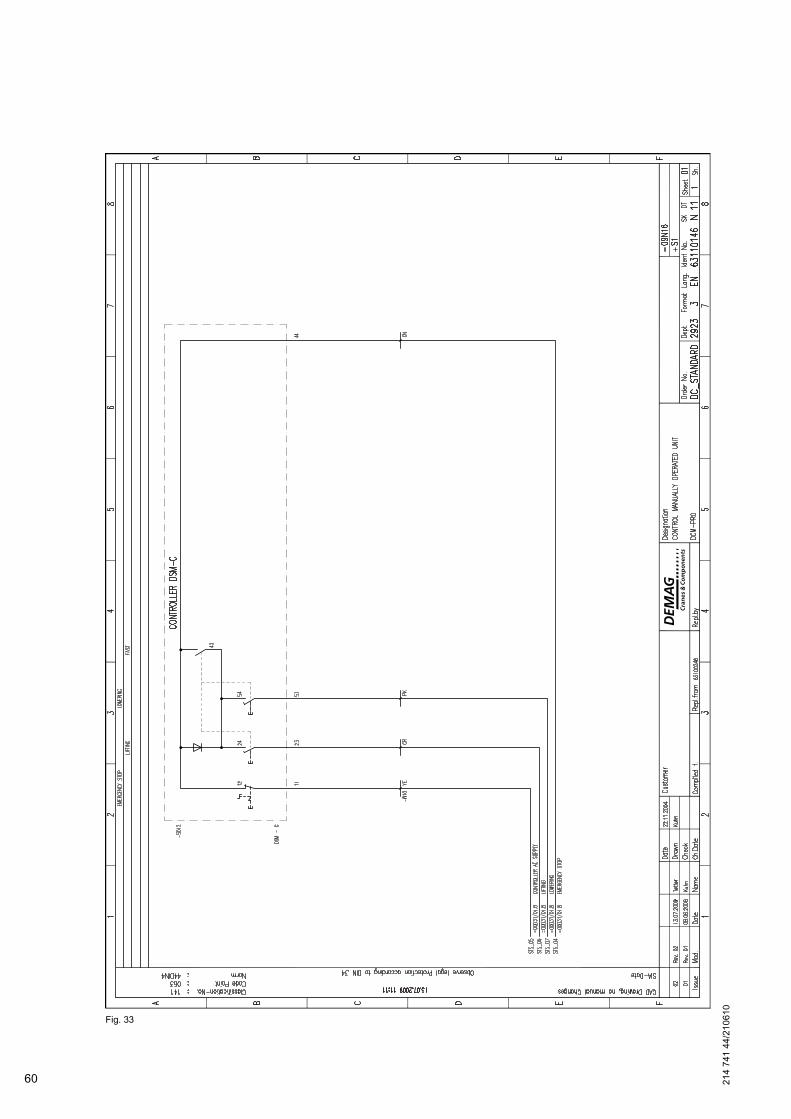
Fig. 33
60 214
741
44/2
1061
0
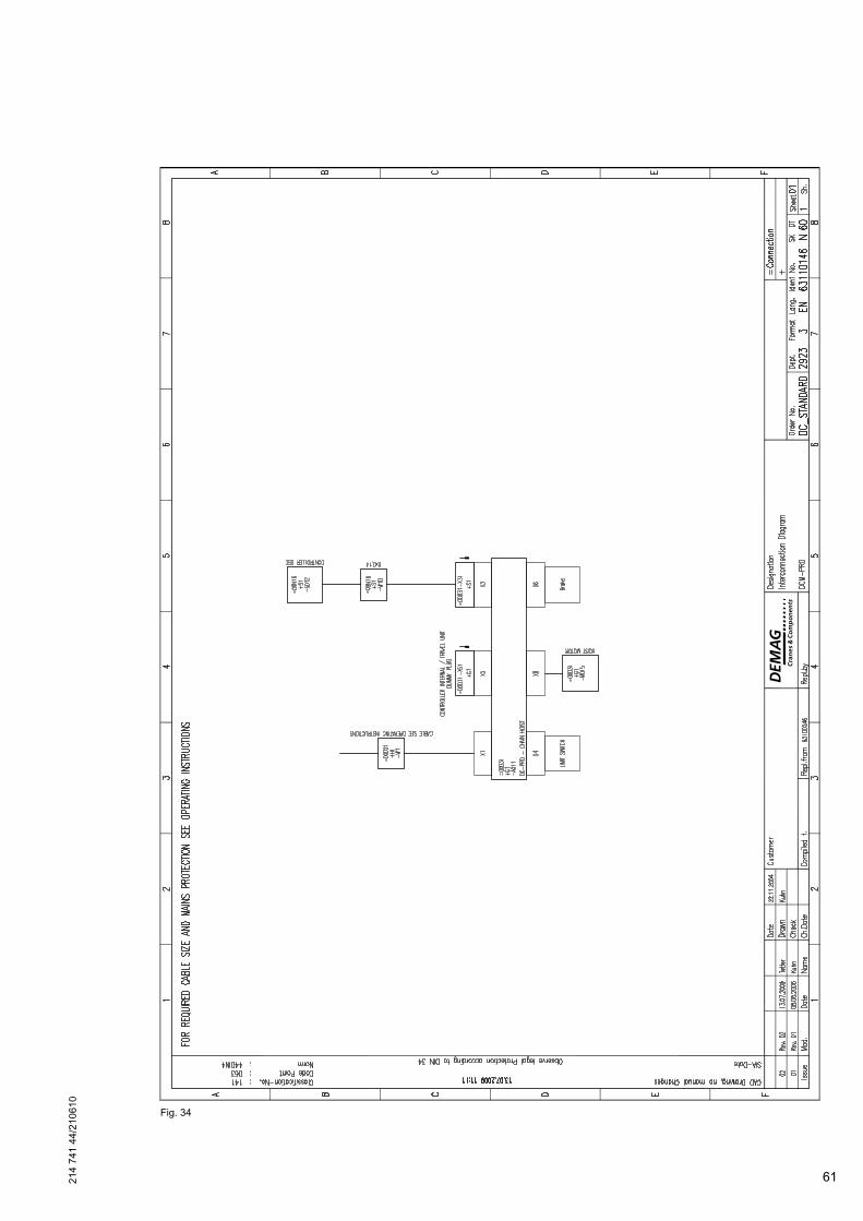
Fig. 34
214
741
44/2
1061
0
61
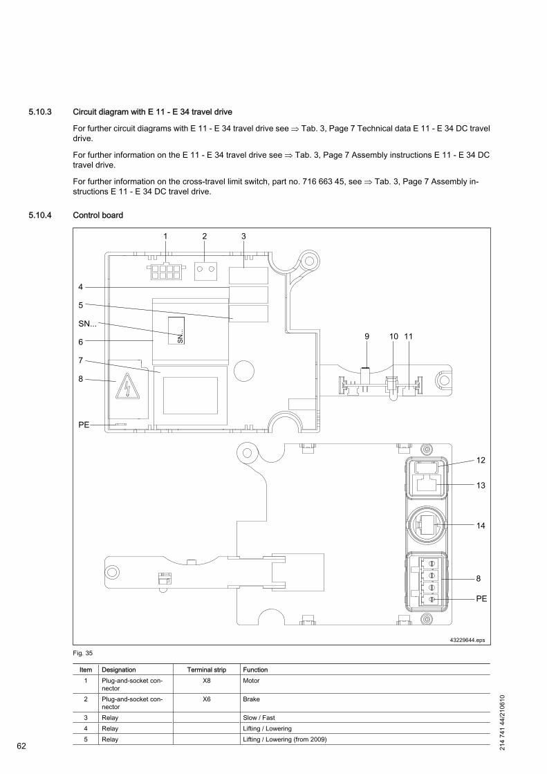
5.10.3 Circuit diagram with E 11 - E 34 travel drive
For further circuit diagrams with E 11 - E 34 travel drive see ⇒ Tab. 3, Page 7 Technical data E 11 - E 34 DC traveldrive.
For further information on the E 11 - E 34 travel drive see ⇒ Tab. 3, Page 7 Assembly instructions E 11 - E 34 DCtravel drive.
For further information on the cross-travel limit switch, part no. 716 663 45, see ⇒ Tab. 3, Page 7 Assembly in‐structions E 11 - E 34 DC travel drive.
5.10.4 Control board
Fig. 35
Item Designation Terminal strip Function1 Plug-and-socket con‐
nectorX8 Motor
2 Plug-and-socket con‐nector
X6 Brake
3 Relay Slow / Fast4 Relay Lifting / Lowering5 Relay Lifting / Lowering (from 2009)
62 214
741
44/2
1061
0
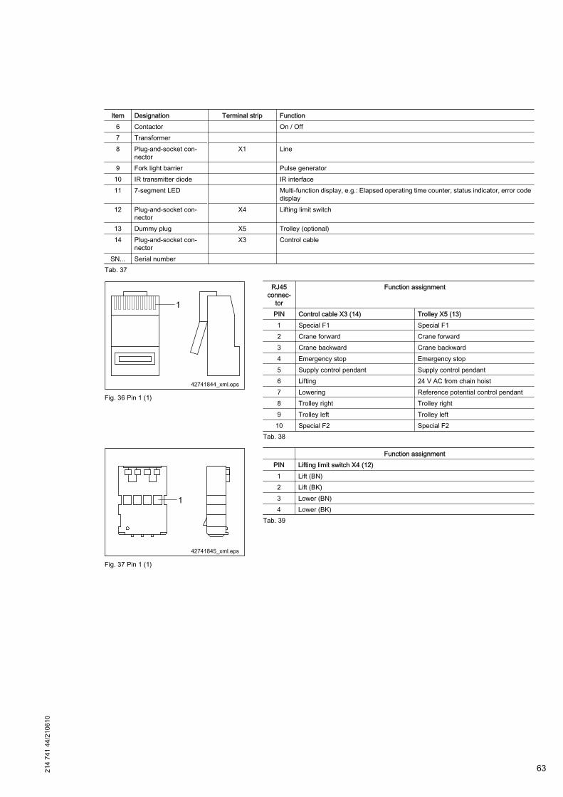
Item Designation Terminal strip Function6 Contactor On / Off7 Transformer 8 Plug-and-socket con‐
nectorX1 Line
9 Fork light barrier Pulse generator10 IR transmitter diode IR interface11 7-segment LED Multi-function display, e.g.: Elapsed operating time counter, status indicator, error code
display12 Plug-and-socket con‐
nectorX4 Lifting limit switch
13 Dummy plug X5 Trolley (optional)14 Plug-and-socket con‐
nectorX3 Control cable
SN... Serial number Tab. 37
Fig. 36 Pin 1 (1)
RJ45connec‐
tor
Function assignment
PIN Control cable X3 (14) Trolley X5 (13)1 Special F1 Special F12 Crane forward Crane forward3 Crane backward Crane backward4 Emergency stop Emergency stop5 Supply control pendant Supply control pendant6 Lifting 24 V AC from chain hoist7 Lowering Reference potential control pendant8 Trolley right Trolley right9 Trolley left Trolley left
10 Special F2 Special F2Tab. 38
Fig. 37 Pin 1 (1)
Function assignmentPIN Lifting limit switch X4 (12)1 Lift (BN)2 Lift (BK)3 Lower (BN)4 Lower (BK)
Tab. 39
214
741
44/2
1061
0
63
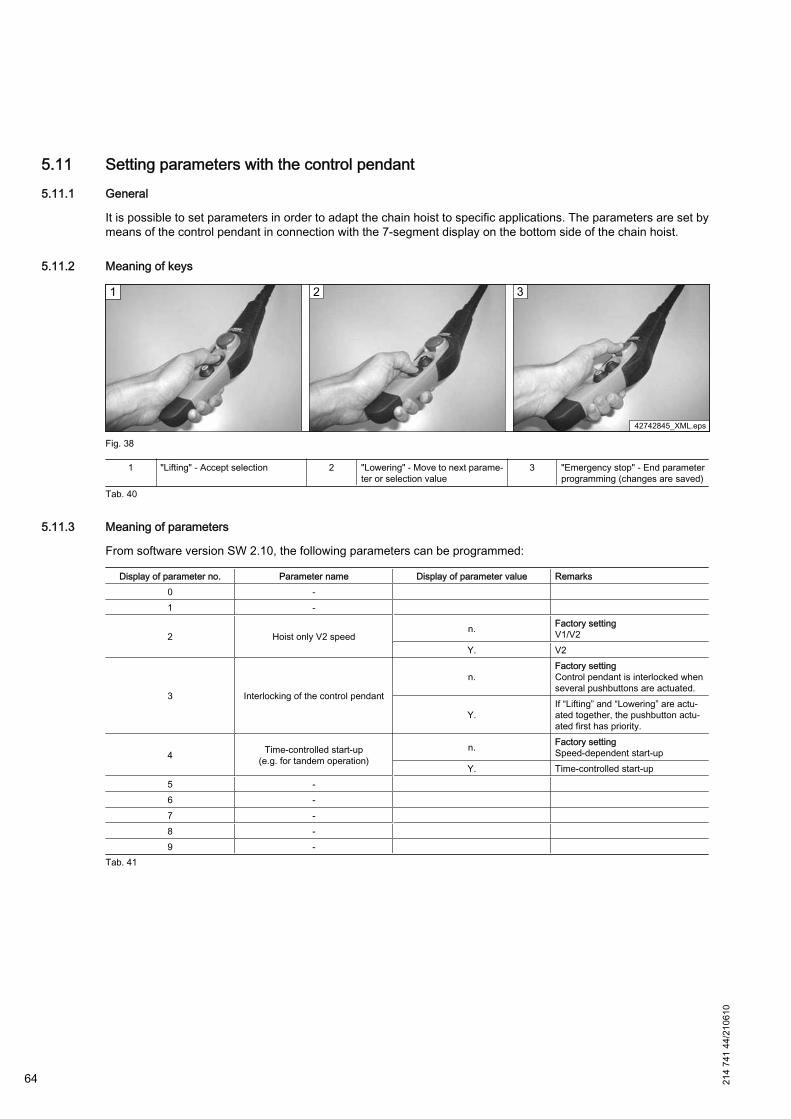
5.11 Setting parameters with the control pendant5.11.1 General
It is possible to set parameters in order to adapt the chain hoist to specific applications. The parameters are set bymeans of the control pendant in connection with the 7-segment display on the bottom side of the chain hoist.
5.11.2 Meaning of keys
Fig. 38
1 "Lifting" - Accept selection 2 "Lowering" - Move to next parame‐ter or selection value
3 "Emergency stop" - End parameterprogramming (changes are saved)
Tab. 40
5.11.3 Meaning of parameters
From software version SW 2.10, the following parameters can be programmed:
Display of parameter no. Parameter name Display of parameter value Remarks0 - 1 -
2 Hoist only V2 speedn. Factory setting
V1/V2Y. V2
3 Interlocking of the control pendant
n.Factory settingControl pendant is interlocked whenseveral pushbuttons are actuated.
Y.If “Lifting” and “Lowering” are actu‐ated together, the pushbutton actu‐ated first has priority.
4 Time-controlled start-up(e.g. for tandem operation)
n. Factory settingSpeed-dependent start-up
Y. Time-controlled start-up5 - 6 - 7 - 8 - 9 -
Tab. 41
64 214
741
44/2
1061
0

5.11.4 Starting parameter setting mode
Fig. 39
1st step:Actuate “Emergency stop”.
2nd step:Press and hold down the "Lift" key and unlockthe emergency stop. Wait for approx. 10 sec‐onds.
3rd step:When "P." is displayed, release the "Lift" key.
7-segment display: (display dark) 7-segment display: (display spot) 7-segment display: P.Tab. 42
Fig. 40
4th step:"P." extinguishes after approx. 2 seconds.Press the "Lift" key and hold down again until"o." (for O.K.) is displayed.
5th step:Release key. The parameter programmingmode is actice now.When the parameter programming mode hasbeen activated, figures "0." to "9." are displayedsuccessively for 2 seconds, each.
6th step:Press the "Lower" key to move faster throughthe menu items.Each figure represents a parameter, see⇒ "Meaning of parameters", Page 64.
7-segment display: o. 7-segment display: 0. → 1. ··· 9. 7-segment display:Tab. 43
214
741
44/2
1061
0
65
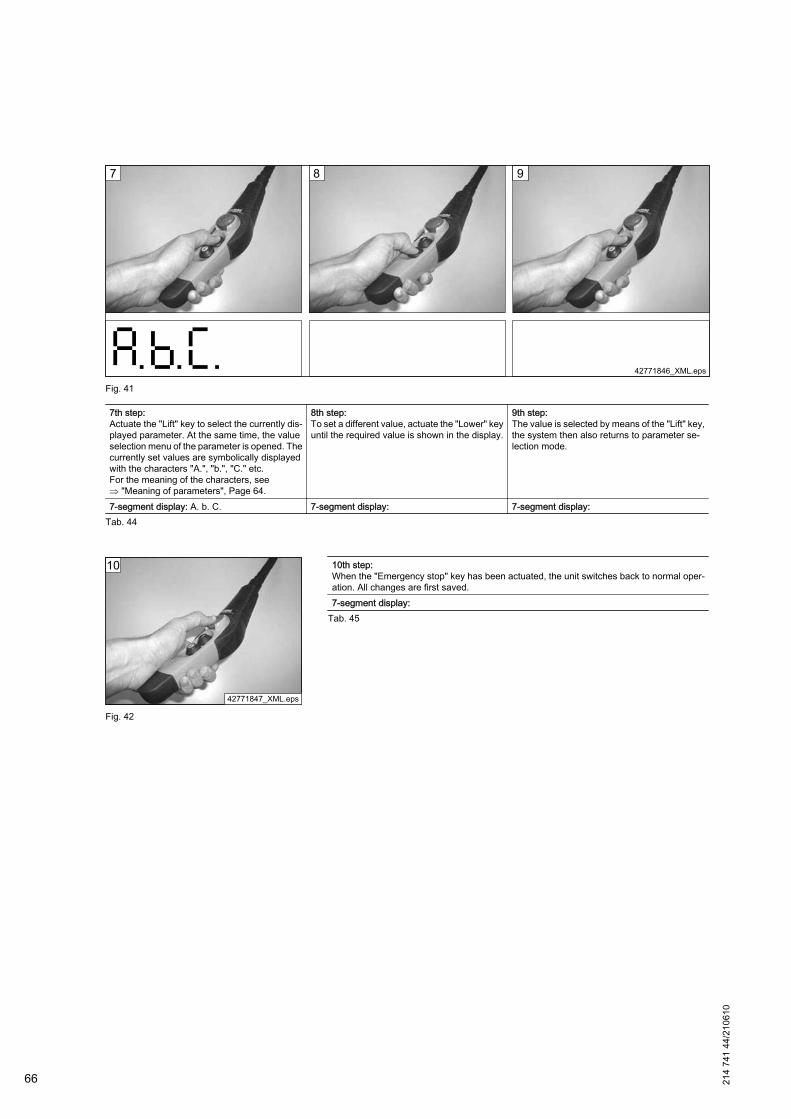
Fig. 41
7th step:Actuate the "Lift" key to select the currently dis‐played parameter. At the same time, the valueselection menu of the parameter is opened. Thecurrently set values are symbolically displayedwith the characters "A.", "b.", "C." etc.For the meaning of the characters, see⇒ "Meaning of parameters", Page 64.
8th step:To set a different value, actuate the "Lower" keyuntil the required value is shown in the display.
9th step:The value is selected by means of the "Lift" key,the system then also returns to parameter se‐lection mode.
7-segment display: A. b. C. 7-segment display: 7-segment display:Tab. 44
Fig. 42
10th step:When the "Emergency stop" key has been actuated, the unit switches back to normal oper‐ation. All changes are first saved.7-segment display:
Tab. 45
66 214
741
44/2
1061
0
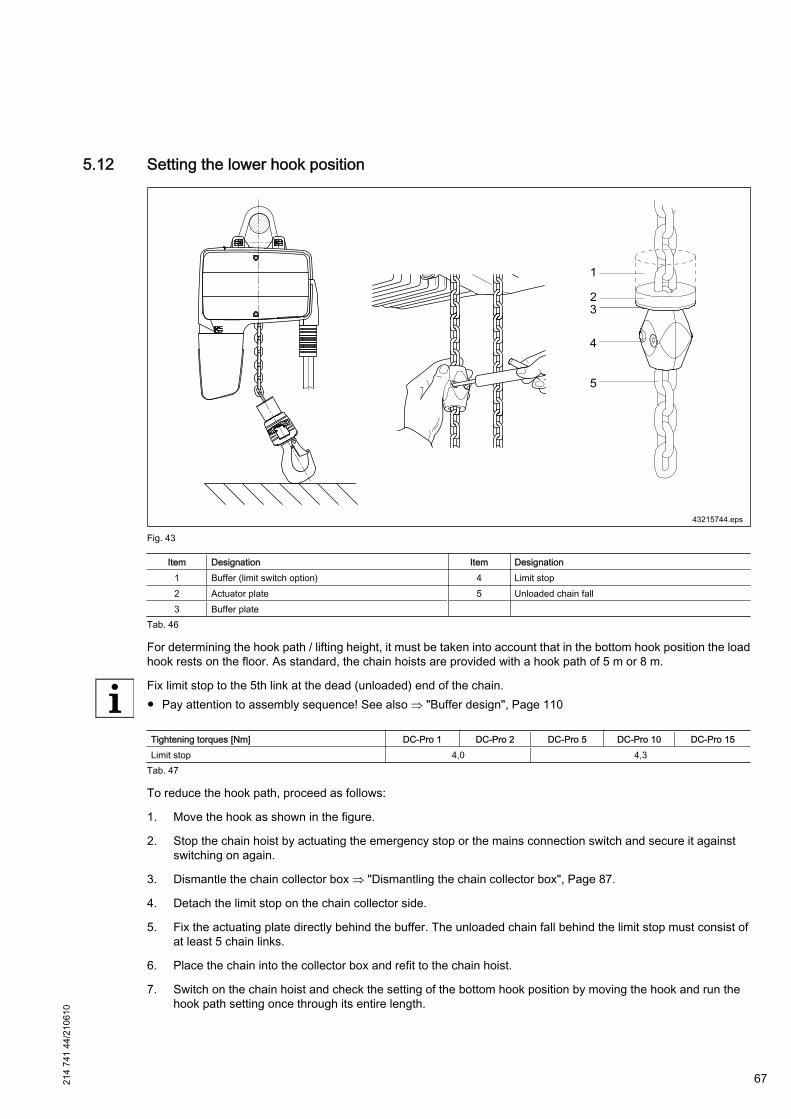
5.12 Setting the lower hook position
Fig. 43
Item Designation Item Designation1 Buffer (limit switch option) 4 Limit stop2 Actuator plate 5 Unloaded chain fall3 Buffer plate
Tab. 46
For determining the hook path / lifting height, it must be taken into account that in the bottom hook position the loadhook rests on the floor. As standard, the chain hoists are provided with a hook path of 5 m or 8 m.
Fix limit stop to the 5th link at the dead (unloaded) end of the chain.● Pay attention to assembly sequence! See also ⇒ "Buffer design", Page 110
Tightening torques [Nm] DC-Pro 1 DC-Pro 2 DC-Pro 5 DC-Pro 10 DC-Pro 15Limit stop 4,0 4,3
Tab. 47
To reduce the hook path, proceed as follows:
1. Move the hook as shown in the figure.
2. Stop the chain hoist by actuating the emergency stop or the mains connection switch and secure it againstswitching on again.
3. Dismantle the chain collector box ⇒ "Dismantling the chain collector box", Page 87.
4. Detach the limit stop on the chain collector side.
5. Fix the actuating plate directly behind the buffer. The unloaded chain fall behind the limit stop must consist ofat least 5 chain links.
6. Place the chain into the collector box and refit to the chain hoist.
7. Switch on the chain hoist and check the setting of the bottom hook position by moving the hook and run thehook path setting once through its entire length.
214
741
44/2
1061
0
67
6 Putting the unit into service for the first time
6.1 Safety instructions when first putting the unit into service
The machine may only be handed over, if its safety has been verified by a corresponding inspection ⇒ "Inspectionswhen first putting into service, handing over", Page 69.
WARNING
When first putting into service, safe operation of the machine is not yet guaranteed.
Machines may only be put into service, when assembly has been completed according to the assemly instructions.
– Putting into service may be carried out by specialist personnel, only.– Before putting into operation check that the safety equipment is fitted / functioning.– Check that the mains voltage and frequency match the data specified on the rating plate.– Move the trolleys by hand and check that they can be moved without resistance by hand over the entire length
of the track section (if existing).– Before starting work ensure that sufficient working clearance is available.– Secure working and danger zone.– Wear protective equipment!
Only trained specialist personnel must be employed for first putting into service since:● it may be necessary to render safety devices or features inoperative when carrying out adjustments or function
checks,● work may need to be performed in the danger zone when first putting into service.
6.2 Inspection regulations
WARNING
Non-compliance with operating and maintenance instructionsDanger to life and limb.Compliance with all inspection regualtions is an integral part of securing the safe operation of the machine.Prescribed tests and inspections must be carried out.All inspections must be arranged at the specified time intervals / points of time and documented by the owner.– Inspection in accordance with relevant national regulations, e.g. UVV/BGV D6 for cranes; UVV/BGV D8 for
winches, hoists and towing devices in Germany.The owner is responsible for ensuring that powered chain hoists are inspected by an expert engineer prior tofirst putting into service and after major modifications have been carried out, before putting into service again.This also applies to manually operated or semi-powered chain hoists with a load capacity of more than 1000kg.
– Adjustment, maintenance and inspection activities and inspection deadlines including specifications concern‐ing replacement of parts/assemblies prescribed in the operating instructions must be observed.
– For the values for noise emission measurement according to DIN 45635 please refer to ⇒ "Noise emission /sound pressure level", Page 28
This work may only be carried out by specialists.
68 214
741
44/2
1061
0
6.3 Inspections prior to putting into service for the first timeBefore putting into service for the first time, the owner is obliged to carry out the following inspections:
Action Section Inspec‐tion
Check continuity of the PE conductor connection - XCheck emergency stop device - XCheck direction of movement ⇒ "Line connection", Page 54 XCheck 7-segment display ⇒ "7-segment display for operating status and
error display", Page 33,⇒ "Software version, operating hours, number of
cycles, operating statuses", Page 33
X
Check chain lubrication (under arduous conditions, the chain must be lubricatedmore frequently)
⇒ "Available hoist chains", Page 93 X
Check function of operating limit switch for lifting ⇒ "Checking the operating limit switches",Page 87
X
Check function of operating limit switch for lowering ⇒ "Checking the operating limit switches",Page 87
X
Check switch-off buffer / switch-off spring / operating limit switch actuator ⇒ "Checking the switch-off buffer / switch-offspring", Page 109,
⇒ "Checking the operating limit switch actuator",Page 88
X
Check control cable and control pendant housing for damage - XCheck operation of the brake - XCheck hook and hook safety catch ⇒ "Checking the load hook", Page 100 X
Tab. 48
6.4 Inspections when first putting into service, handing over
WARNING
Impermissible operationThere is danger to life and limb when the machine is operated without previous inspection.Machines may only be put into service, when they have been inspected according to the accident preventionregulations.
By means of suitable measures carried out by the owner or on his behalf, the owner ensures that the load handlingattachments and machinery ready for operation function in complete safety before first being put into service. Thespecified measures must allow for the static and dynamic features of the machinery.
The following checks must be carried out when first putting into service:● The proper condition of the supporting structure and the load capacity of the chain hoist.● Safety devices must be completely fitted and effective.● Clearances and safety distances must be complied with.● The emergency stop device must be checked by actuating the emergency stop.
When putting into service for the first time, all possibilities of intended use must be checked at the correspondingmaximum permissible load. The functioning of the safety devices must be checked (e.g. by lifting an overload). Atthe same time the behaviour of the chain hoist in the case of misuse must be checked.
Before handing over, different inspections of the machine must be arranged for:● Inspection for suitability for operation● Acceptance test
As soon as the safe operating status of the chain hoist is ensured, the test and inspection records can be prepared.
When handing over the machine, the test and inspection records (test and inspection booklet; observe the relevantcountry-specific regulations) are handed over.
After the machine has been handed over, it may be used as intended.
214
741
44/2
1061
0
69
7 Operation
7.1 Safety instructions for operation
WARNING
Inappropriate operationThere is a risk of injury in the case of inappropriate operation.Inappropriate operation may result in serious personal injury and / or material damage. The unit may only beoperated by authorized, instructed personnel in compliance with all accident prevention and safety regulations.National regulations for the use of crane and lifting equipment must be observed and complied with.– The customer must arrange for the training of the operating personnel.
WARNING
Crushing hazardWhen lifting or lowering loads there is a risk of injury due to parts of the body being crushed or clothing or hairbecoming entangled.– Do not touch the chain.– Do not reach into the upper or lower chain entry point.– Do not reach into the coupling area when changing the quick-release coupling of the Manulift.– Do not reach between hook throat and load handling attachment when lifting loads.– Persons must not stay in the immediate danger zone when depositing the load.
WARNING
Risk of burningThere is a risk of burning when touching the chain hoist during operation.Do not touch the hot motor housing.
WARNING
Suspended load! Falling parts!There is danger to life and limb, when lifted loads fall down.Persons must keep out of the danger zone.– Keep a sufficient safety distance.– Do not walk under the suspended load.– It is not allowed to lift loads above persons.– Wear protective equipment!
WARNING
Non-compliance with operating regulations / regulations regarding industrial safetyThere is a danger to life and limb due to the non-compliance with valid standards.Machines may only be operated in compliance with the country-specific operating regulations, e.g. Cranes BGVD6 (VBG 9) in Germany.– If required, apply a copy of the relevant operating regulations, ident. no. 206 093 44, at a suitable place where
operators can read them at any time (e.g. at the mains connection switch).
The machine must not be put into operation or must be taken out of service immediately if any defects or irregularitiesrelating to operating safety and reliability or function are detected.
Safety devices must not be rendered inoperative or modified in contradiction to their intended use.
70 214
741
44/2
1061
0
Ensuring safe operation
Special local conditions or special applications can lead to situations which were not known when this chapter waswritten. In this case, the owner must ensure safe operation or take the machine out of service until measures forsafe operation have been clarified and implemented in agreement with Demag or other responsible bodies.
In the event of a stoppage (e.g. if defects regarding safe and reliable operation are detected, in emergency situations,in the event of operating malfunctions, for repairs and maintenance purposes, if damage is detected or after finishingwork), the operator must carry out all prescribed safety measures or observe that they are automatically carried out.
Work on electrical equipment may only be carried out by qualified electricians.
7.2 Switching on
7.2.1 Inspections when starting work
Before starting work, the operator must be satisfied that the machine is in safe and correct operating condition.
Ensure that nobody is endangered by operation of the hoist before switching it on or putting it into operation. If theoperator notices persons who may be exposed to a risk to health or personal safety by operation of the installation,he must stop operation immediately and may not resume operation until the persons are outside the danger zone.
In the event of defects which endanger safe and reliable operation, the chain hoist must be taken out of servicewithout delay. Defects relevant to safety in this sense are, for example:● Damage to electrical devices, cables or insulation,● Delayed functioning or failure of brakes and safety devices,● Missing covers or housing parts or● Damage to the chain or to supporting parts.
Anybody who identifies an immediate danger of personal injury must actuate the emergency stop without delay. Thisalso applies in the case of damage occurring to parts of the machine and equipment which makes immediate stop‐page necessary.
When the chain hoist has been stopped as a consequence of safety-relevant defects by an emergency stop, it mustbe secured against putting into operation again until an experienced technician is satisfied that the cause of thehazard situation has been eliminated and that operation of the machine is possible without any hazard.
Before starting work:● Wear protective equipment!● Check that no persons are in the danger zone of the unit.
7.2.2 Functional tests
Instructions for users within the scope of application of the BGV D06 accident prevention regulations:
In accordance with BGV D06, the crane operator must also check functioning of the emergency stop device whenstarting work. This does not apply to slipping clutches used as an emergency-stop device which need not be checkedwhen starting work (BGV D06, §30). DC chain hoists are fitted with a slipping clutch as an emergency-stop devicewhich needs not be checked by the crane operator, therefore a device for by-passing the limit switches which areapproached during normal operation is not fitted.
Before starting work the main functions of the machine must be checked:
214
741
44/2
1061
0
71
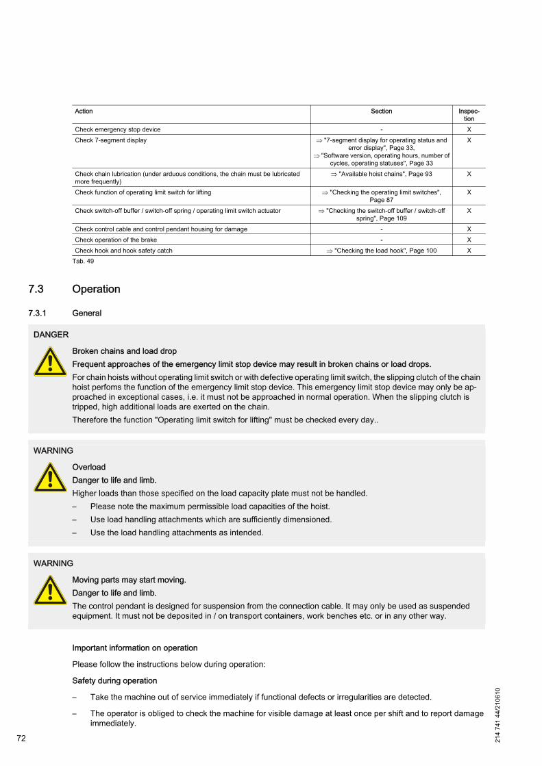
Action Section Inspec‐tion
Check emergency stop device - XCheck 7-segment display ⇒ "7-segment display for operating status and
error display", Page 33,⇒ "Software version, operating hours, number of
cycles, operating statuses", Page 33
X
Check chain lubrication (under arduous conditions, the chain must be lubricatedmore frequently)
⇒ "Available hoist chains", Page 93 X
Check function of operating limit switch for lifting ⇒ "Checking the operating limit switches",Page 87
X
Check switch-off buffer / switch-off spring / operating limit switch actuator ⇒ "Checking the switch-off buffer / switch-offspring", Page 109
X
Check control cable and control pendant housing for damage - XCheck operation of the brake - XCheck hook and hook safety catch ⇒ "Checking the load hook", Page 100 X
Tab. 49
7.3 Operation
7.3.1 General
DANGER
Broken chains and load dropFrequent approaches of the emergency limit stop device may result in broken chains or load drops.For chain hoists without operating limit switch or with defective operating limit switch, the slipping clutch of the chainhoist perfoms the function of the emergency limit stop device. This emergency limit stop device may only be ap‐proached in exceptional cases, i.e. it must not be approached in normal operation. When the slipping clutch istripped, high additional loads are exerted on the chain.Therefore the function "Operating limit switch for lifting" must be checked every day..
WARNING
OverloadDanger to life and limb.Higher loads than those specified on the load capacity plate must not be handled.– Please note the maximum permissible load capacities of the hoist.– Use load handling attachments which are sufficiently dimensioned.– Use the load handling attachments as intended.
WARNING
Moving parts may start moving.Danger to life and limb.The control pendant is designed for suspension from the connection cable. It may only be used as suspendedequipment. It must not be deposited in / on transport containers, work benches etc. or in any other way.
Important information on operation
Please follow the instructions below during operation:
Safety during operation
– Take the machine out of service immediately if functional defects or irregularities are detected.
– The operator is obliged to check the machine for visible damage at least once per shift and to report damageimmediately.
72 214
741
44/2
1061
0

– Do not render safety devices inoperative.
– Limits must not be approached in normal operation, e.g. emergency stop devices (emergency limit switches),emergency limit stop devices (slipping clutch or emergency limit switch), track and end buffers for stoppingmotion of the trolley or crane, hook assemblies or bottom block against end stops. Continuous approaches ofthese limits may result in severe damage on the chain hoist up to chain breakage.
– Pay attention to regulations pertaining to the correct loading of chains.
– Do not reach into rotating parts and maintain a sufficient safety distance to prevent clothing, parts of the bodyor hair becoming entangled.
Load pick-up
– The load handling attachment and load must be flexibly suspended. Rigid connections cause uncontrolledforces and lead to fatigue fracture. To protect the chain from impermissible torsion when the load turns, move‐ment of the hook assembly/bottom block must not be restricted.
– The bottom block must not be twisted or turned over for 2/1 reeving arrangements; chain links facing the samedirection must be arranged opposite each other without being twisted.
– When attaching the load, ensure that loads or the load handling attachment do not slip out of the hook or thatloads do not fall over, fall apart, slip or roll off when being picked up and deposited.
– When the load is lifted, the hook must move to an upright position so that the safety catch is not loaded by theload handling slings and, as a result, may be damaged.
– Transporting persons is not permitted.
– The load specified on the capacity plate indicates the highest permissible load which must not be exceeded. Itis the sum total of lifting load and load handling attachment. Only approved load handling attachments may beused. The load capacity of the load handling attachment must not be exceeded.
Moving the load
– During lifting and travelling motions the operator must take a position which provides a free view on the dangerzone or a second person must be available who has a view on the danger zone.
– Hoists / trolleys / cranes with push travel may only be moved by pulling or pushing on the load, bottom blockor load hook assembly. Never pull on the control pendant.
– Hand-moved loads must be guided by hand. The load must never be thrown.
– Do not handle suspended loads above persons.
– Do not pull or drag suspended loads at an angle. At an angle higher than 4° the chain drive may get damaged.
– Do not pull free fixed or obstructed loads with the chain hoist.
– Do not leave suspended loads unsupervised.
– Do not allow the chain to pass over edges or to be used as a load bearing sling.
– Do not allow loads to drop when the chain is in a slack condition.
– Vibration from the load being transported (e.g. when the load is deposited on vibrating machinery) must not betransmitted to the crane.
– Chain hoists must be suspended in such a way that they do not collide with stationary equipment and structures,e.g. when slewing pivoting cranes.
– Do not snatch the load at full speed.
– Avoid inching operation.
214
741
44/2
1061
0
73
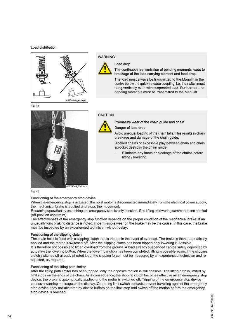
Load distribution
Fig. 44
WARNING
Load dropThe continuous transmission of bending moments leads tobreakage of the load carrying element and load drop.The load must always be transmitted to the Manulift in thecentre below the quick-release coupling, i.e. the switch musthang vertically even with suspended load. Furthermore nobending moments must be transmitted to the Manulift.
Fig. 45
CAUTION
Premature wear of the chain guide and chainDanger of load dropAvoid unequal loading of the chain falls. This results in chainbreakage and damage of the chain guide.Blocked chains or excessive play between chain and chainsprocket destroys the chain guide.– Eliminate any knots or blockage of the chains before
lifting / lowering.
Functioning of the emergency stop deviceWhen the emergency stop is actuated, the hoist motor is disconnected immediately from the electrical power supply,the mechanical brake is applied and stops the movement.Resuming operation by unlatching the emergency stop is only possible, if no lifting or lowering commands are applied(off-position constraint).The effectiveness of the emergency stop function depends on the proper condition of the mechanical brake. If anunusually long braking distance is noted, impermissible wear on the brake may be the cause. In this case, the brakemust be inspected by an experienced technician without delay.
Functioning of the slipping clutchThe chain hoist is fitted with a slipping clutch that is tripped in the event of overload. The brake is then automaticallyapplied and the motor is switched off. After the slipping clutch has been tripped only lowering is possible.It is therefore not possible to lift an overload from the ground. A load already suspended can be safely deposited byactuating the lowering button. When the lowering motion has been completed, lifting is possible again. If the slippingclutch switches off already at rated load, the slipping force must be measured by an experienced technician and re-adjusted, as required.
Functioning of the lifting path limiterAfter the lifting path limiter has been tripped, only the opposite motion is still possible. The lifting path is limited bylimit stops on the ends of the chain. As a consequence, the slipping clutch becomes effective as an emergency stopdevice, the brake is automatically applied and the motor is switched off. Tripping of the emergency stop devicecauses a warning message on the display. Operating limit switch contacts prevent travelling against the emergencystop device, they are actuated by elastic buffers on the limit stop and switch off the motion before the emergencystop device is reached.
74 214
741
44/2
1061
0

7.3.2 Manulift
Belt sling
Fig. 46
CAUTION
Load falling downIn order to ensure the safe use of the belt sling please notethe following:– The belt sling must uniformly support the load with its
whole width.– The angle between legs must not exceed 120°.– It must not be used for handling loads which have
sharp edges or coarse surfaces.– It must not be used for handling loads with tempera‐
tures higher than 50 °C.– The sling must not come into contact with chemicals.
The belt sling is used for handling asymmetrical or large-area parts (e.g. discs). To this effect, the belt is tightenedby pulling the free end so that the part to be handled cannot drop out.
After the handling cycle has been finished, the loop can be loosened and the belt sling be opened by lifting theclosing eye.
Pantograph tongs
Fig. 47
CAUTION
Load falling offIn order to ensure the safe use of the pantograph tongsplease note the following:– Loads must always be gripped in the centre.– The clamping jaws must have full contact with the load
or grip it from below.– The tongs must never be used for handling bar stock
and compressible goods.– When using pantograph-type tongs which hold the
load by contact pressure (rubber-lined jaws), the sur‐faces of the loads to be handled must be free from oiland grease, and dry.
– The jaw capacity of the tongs must be suitable for thedimensions of the load to be handled. The permissiblejaw capacity is indicated by a coloured mark.
For gripping, the open tongs are set down on the load to be handled. This automatically unlocks the tongs. The jawsclose and the load is gripped when the tongs are lifted.
When depositing loads, the tongs must be lowered until the jaws are automatically locked in the open position sothat they can be lifted off.
Locking and unlocking (for opening and closing) is effected by the tongs’ dead weight. The tongs need not beoperated manually.
214
741
44/2
1061
0
75

Open hook
Fig. 48
CAUTION
Load falling downIn order to ensure the safe use of the open hook please notethe following:– In order to avoid that the load slips off, the loads to be
picked up may only be supported by the horizontal partof the hook throat.
– The hook throat must remain horizontal even underload.
– Loads must never be handled with the tip of the hook.
7.4 Emergency stop
Fig. 49 Position of the emergency stop device (1)
WARNING
Unauthorised, negligent or accidental restarting.Danger to life and limb.Check to ensure that the reason for the emergency stop has been eliminated before the machine is restarted.The emergency-stop device must not be used to switch off the machine in normal operation.
Every chain hoist features an emergency-stop device with which all motions can be stopped in the event of a hazard.
The emergency-stop is arranged in a clearly visible position on the control pendant. Anybody who identifies animmediate danger of personal injury must actuate the emergency stop without delay. This also applies in the caseof damage occurring to parts of the machine and equipment which makes immediate stoppage and securing of theinstallation necessary.
76 214
741
44/2
1061
0
● To actuate the emergency-stop, press until it reaches the end stop. It then locks automatically and the chain hoistis shut down.
● To unlock the actuated emergency-stop, turn the knob in the direction of the arrow (clockwise) and release.
Following an emergency stop, do not switch the machine on again until you are satisfied that:● the cause which led to actuation of this function has been rectified and● continued operation of the machine constitutes no further hazard.
Control pendant
Depending on the requirements the Demag chain hoist can be equipped with different control pendants. The oper‐ation of the control pendant and the assigment of buttons can be seen in the corresponding brochures, see⇒ Tab. 3, Page 7.
7.5 Taking out of service
7.5.1 Taking out of service in the case of faults
The machine must be switched off immediately in the event of the following faults:● In the event of damage to electrical devices and cables as well as parts of the insulation.● Brake and safety device failure.
7.5.2 Taking the hoist out of service on finishing work
The following measures must be taken when finishing work or leaving the working area:● Position the hoist unit outside the travel area.● Drive the unloaded hoist unit into the resting position.● Actuate the emergency stop.● Switch off the hoist unit power supply at the mains connection or isolator switch.
7.5.3 Taking the unit out of service for maintenance and repairs
1. Switch off the mains connection or isolator switch before commencing maintenance and repair work.
2. Secure the mains connection switch with a padlock to prevent unauthorised or accidental reconnection to thesupply.
3. Only carry out maintenance work on the chain hoist when the load has been removed.
4. Stop all moving parts and ensure that they cannot start moving while maintenance work is being performed.
5. Observe the relevant accident prevention regulations, instructions concerning appropriate use and statutoryregulations for operation and maintenance.
6. Observe the relevant safety regulations when repairing electrical equipment.
214
741
44/2
1061
0
77

8 Maintenance / repair
8.1 Safety Instructions for maintenance / repairIn the following sections maintenance work is described which is necessary for optimum and trouble-free operationof the device.
DANGER
Live componentsDanger to life and limb.Work on electrical equipment may only be carried out by qualified specialist personnel (⇒ "Definition of personnel",Page 10 ) in compliance with the safety instructions.Before starting work, the electrical supply must be switched off. The mains connection or isolator switch must besecured against unauthorized or accidental reconnection by means of a padlock.
WARNING
Risk of burningThere is a risk of burning when touching the chain hoist after operation.Do not touch the hot motor housing. Let motor cool down before starting maintenance and repair work.
WARNING
Inappropriate maintenanceDanger to life and limb. Danger of material damage.Maintenance and repair work may only be carried out by authorized, instructed personnel (⇒ "Definition of per‐sonnel", Page 10 ) in compliance with the safety instructions.– Secure working and danger zone.– When using a working platform for maintenace and repair work, only systems designed for passenger trans‐
port should be used that provide for a stable position and work without any risk.– Only suitable, tested and calibrated tools and accessories may be used for maintenance and repair work.– Only use approved spare parts, see also ⇒ "Use of spare parts", Page 9.– Wear protective equipment!– Caution on open sharp-edged parts! Risk of injury!– Ensure order and cleanliness at the workplace. Machine parts or fittings that are not required must be stored
so that they cannot fall down.– Appropriately fit component parts. Tighten screws with the prescribed tightening torque. Inappropriately fixed
component parts may fall down and result in severe injuries.– Welding work may only be carried out by persons having a special qualification. The requirements of DIN
regarding welding work must be complied with. The electrode holder and earth must be connected to the sameassembly when welding work is carried out. Otherwise serious damage may be caused to the hoist. Trolleysmust not be welded or drilled.
– Customer-specific regulations must be observed.
CAUTION
Loose connectionsLoose connections mean danger for life and limb or risk of machine damage.Metal nuts featuring a locking element (self-locking nuts) are mainly used for Demag chain hoists.– Self-locking nuts must not be replaced by other types of nut.
78 214
741
44/2
1061
0
CAUTION
Risk of injury!Oils and lubricants may be dangerous to health.Contact with these media may lead to serious damage to health (poisoning, allergy, skin irritation etc.).
CAUTION
Risk of injury!Leaking oils and lubricants are hazard sources due to increased slippery.Released oils and lubricants must immediately be absorbed by means of sawdust or oil absorbent and disposedof in an environmentally sound way.
8.2 Basic information on maintenance
General information on maintenance/repair
The specified inspection and maintenance intervals (⇒ "Inspection and maintenance schedule", Page 84) applyto normal operating conditions of the chain hoist. In the course of the annual inspection, all wearing parts are checked.
If routine maintenance reveals that the intervals are too long, they should be adapted to the specific operatingconditions.
Electrical components
In the circuits, only fuse links with specified amperage and tripping characteristics may be used. Defective fuse linksmust not be bridged.
When working on machines or machine equipment the following must be observed:
1. Wear personal protection equipment.
2. Before starting maintenance work, switch off the mains connection switch and protect it against unauthorizedor accidental restarting by locking it with a padlock.
3. Ensure that the chain hoist is switched off, checked for being de-energized and, in special cases, isolated,
4. Only carry out maintenance work on the chain hoist when the load has been removed.
5. Ensure appropriate clearance for working. Ensure order and cleanliness at the workplace. Components andtools being loose or lying around may cause accidents.
6. Stop all moving parts and ensure that they cannot start moving while maintenance work is being performed.
7. Observe the relevant accident prevention regulations and statutory regulations for operation and maintenance.
8. Observe the relevant safety regulations when repairing electrical equipment.
Maintenance work which is not possible from the floor may only be carried out from work stands or platforms. If thereis a risk of objects falling down, the danger zone below the chain hoist must be made safe.
Instructions for repair work in the course of operation
If maintenance work on the chain hoist must be carried out in the course of operation, special safety precautions arenecessary, depending on the operating situation. In each individual case, the owner or the person assigned by himmust check whether the maintenance work may be carried out in the course of operation without risk of personalinjury and, taking into account the local conditions, implement all necessary safety precautions.
Replace damaged or deformed spring clip fasteners and split sleeves.
Defective bolted connections must be replaced.
Ensure that operating and auxiliary materials and replaced parts are disposed of in an environmentally friendlymanner.21
4 74
1 44
/210
610
79
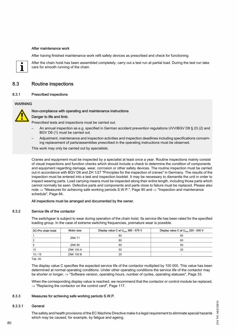
After maintenance work
After having finished maintenance work refit safety devices as prescribed and check for functioning.
After the chain hoist has been assembled completely, carry out a test run at partial load. During the test run takecare for smooth running of the chain.
8.3 Routine inspections
8.3.1 Prescribed inspections
WARNING
Non-compliance with operating and maintenance instructionsDanger to life and limb.Prescribed tests and inspections must be carried out.– An annual inspection as e.g. specified in German accident prevention regulations UVV/BGV D8 § 23 (2) and
BGV D6 (1) must be carried out.– Adjustment, maintenance and inspection activities and inspection deadlines including specifications concern‐
ing replacement of parts/assemblies prescribed in the operating instructions must be observed.This work may only be carried out by specialists.
Cranes and equipment must be inspected by a specialist at least once a year. Routine inspections mainly consistof visual inspections and function checks which should include a check to determine the condition of componentsand equipment regarding damage, wear, corrosion or other safety devices. The routine inspection must be carriedout in accordance with BGV D6 and ZH 1/27 "Principles for the inspection of cranes" in Germany. The results of theinspection must be entered into a test and inspection booklet. It may be necessary to dismantle the unit in order toinspect wearing parts. Load carrying means must be inspected along their entire length, including those parts whichcannot normally be seen. Defective parts and components and parts close to failure must be replaced. Please alsonote ⇒ "Measures for achieving safe working periods S.W.P.", Page 80 and ⇒ "Inspection and maintenanceschedule", Page 84.
All inspections must be arranged and documented by the owner.
8.3.2 Service life of the contactor
The switchgear is subject to wear during operation of the chain hoist. Its service life has been rated for the specifiedloading group. In the case of extreme switching frequencies, premature wear is possible.
DC-Pro chain hoist Motor size Display value C at Unom 380 - 575 V Display value C at Unom 220 - 240 V
1ZNK 71
80 802 80 605 ZNK 80 60 5010 ZNK 100 A 50 2010 / 15 ZNK 100 B 20 -
Tab. 50
The display value C specifies the expected service life of the contactor multiplied by 100 000. This value has beendetermined at normal operating conditions. Under other operating conditions the service life of the contactor maybe shorter or longer, ⇒ "Software version, operating hours, number of cycles, operating statuses", Page 33.
When the corresponding display value is reached, we recommend that the contactor or control module be replaced,⇒ "Replacing the contactor on the control card", Page 117.
8.3.3 Measures for achieving safe working periods S.W.P.
8.3.3.1 General
The safety and health provisions of the EC Machine Directive make it a legal requirement to eliminate special hazardswhich may be caused, for example, by fatigue and ageing.
80 214
741
44/2
1061
0
This requirement is also reflected in the third supplement to German accident prevention regulations UVV/BGV D8(VBG 8) of 1.4.1996.
This requirement obliges the owner of serial hoist units to determine the actual duration of service of the chain hoiston the basis of the operating hours, load spectra and/or recording factors. This is based on FEM 9.755/06.1993Measures for achieving safe working periods for powered serial hoist units (S.W.P.).
The objective of this rule is to determine measures for achieving safe working periods over the entire duration ofservice, although, according to the state-of-the-art, the hoist units are designed for specific periods of operation.Premature failure cannot, however, be ruled out.
The following items have been taken from FEM rule 9.755 with reference to the electric chain hoist:
1. The actual duration of service determined on the basis of operating time and load must be documented at leastonce per year.
2. The operating time Ti (number of operating hours) can be estimated or read on an elapsed time indicator.
3. The load kmi (load spectrum) must be estimated.
4. The value determined for operating time Ti using an elapsed time indicator must be multiplied by the type ofrecording factor f = 1,1.
5. The value determined for the estimated operating hours and load spectrum must be multiplied by the type ofrecording factor f = 1,2.
6. The actual duration of service S is calculated as: S = kmi • Ti • f
7. A general overhaul must be carried out when the theoretical duration of service is reached.
8. All checks and inspections and the general overhaul must be arranged by the owner of the hoist unit.
A general overhaul is defined as:
Inspection of the machinery for the purpose of detecting all defective components and/or components and partsclose to failure and the replacement of all such components and parts. Following a general overhaul, the machineryis in a condition similar to that of the same machinery in new condition as far as the principle of operation andperformance values are concerned.
For electric chain hoists classified according to FEM 9.511, the following theoretical durations of service apply (con‐verted into full load hours):
Group of mechanisms 1Cm 1Bm 1Am 2m 2m+ 3m 4mDuration of service / full load hours[h]
200 400 800 1600 1900 3200 6300
Tab. 51
The actual duration of service is considerably increased if the chain hoist is only operated with partial load. For achain hoist operated on average with half load, for example, this results in an 8-fold increase in the actual durationof service, with operation at one quarter of the full load, a 64-fold increase.
8.3.3.2 Calculating the actual duration of service S
The actual duration of service S of the electric chain hoist can be determined as follows:
S = kmi • Ti • f
kmi : Actual load spectrum factor
Ti : Number of operating hours
f : Factor depending on the type of recording
Calculating the number of operating hours (operating time) Ti (by the owner)
The operating time can be calculated by means of an elapsed time indicator or according to the following method:
Operating time per inspection interval:
214
741
44/2
1061
0
81
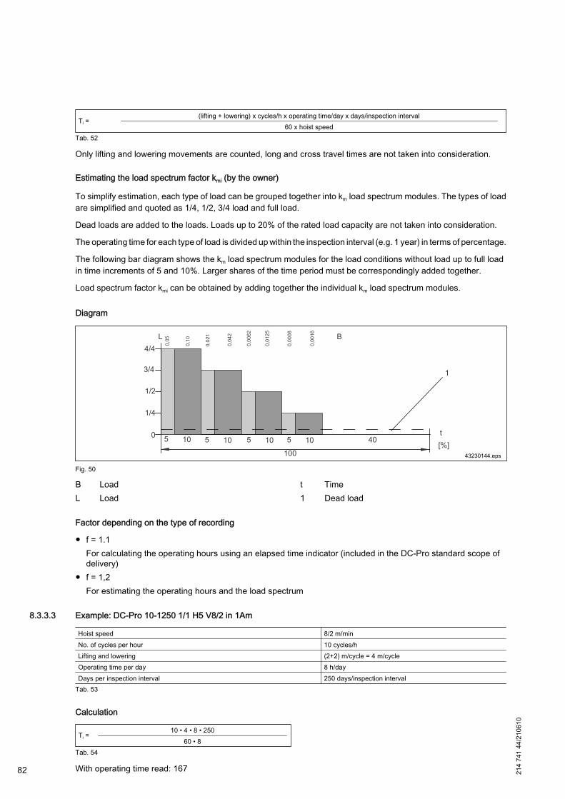
Ti =(lifting + lowering) x cycles/h x operating time/day x days/inspection interval
60 x hoist speedTab. 52
Only lifting and lowering movements are counted, long and cross travel times are not taken into consideration.
Estimating the load spectrum factor kmi (by the owner)
To simplify estimation, each type of load can be grouped together into km load spectrum modules. The types of loadare simplified and quoted as 1/4, 1/2, 3/4 load and full load.
Dead loads are added to the loads. Loads up to 20% of the rated load capacity are not taken into consideration.
The operating time for each type of load is divided up within the inspection interval (e.g. 1 year) in terms of percentage.
The following bar diagram shows the km load spectrum modules for the load conditions without load up to full loadin time increments of 5 and 10%. Larger shares of the time period must be correspondingly added together.
Load spectrum factor kmi can be obtained by adding together the individual km load spectrum modules.
Diagram
Fig. 50
B LoadL Load
t Time1 Dead load
Factor depending on the type of recording
● f = 1.1For calculating the operating hours using an elapsed time indicator (included in the DC-Pro standard scope ofdelivery)
● f = 1,2For estimating the operating hours and the load spectrum
8.3.3.3 Example: DC-Pro 10-1250 1/1 H5 V8/2 in 1Am
Hoist speed 8/2 m/minNo. of cycles per hour 10 cycles/hLifting and lowering (2+2) m/cycle = 4 m/cycleOperating time per day 8 h/dayDays per inspection interval 250 days/inspection interval
Tab. 53
Calculation
Ti =10 • 4 • 8 • 250
60 • 8Tab. 54
With operating time read: 16782 214
741
44/2
1061
0
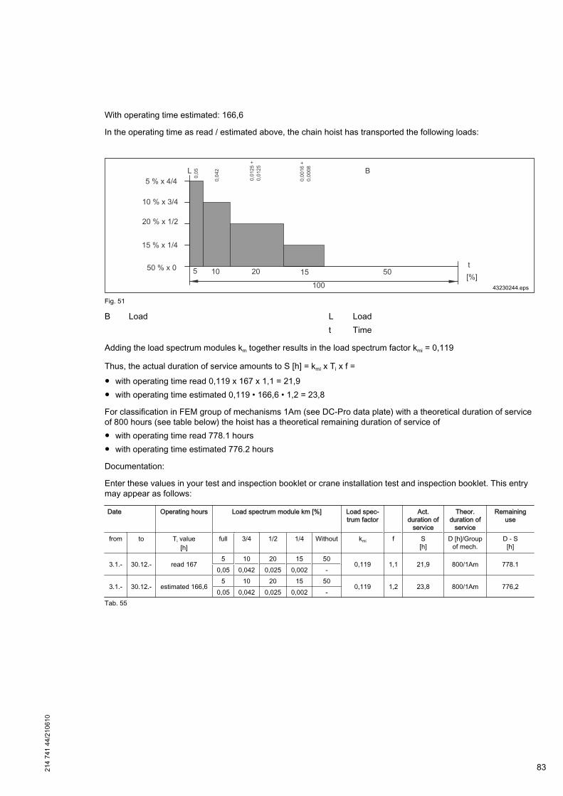
With operating time estimated: 166,6
In the operating time as read / estimated above, the chain hoist has transported the following loads:
Fig. 51
B Load L Loadt Time
Adding the load spectrum modules km together results in the load spectrum factor kmi = 0,119
Thus, the actual duration of service amounts to S [h] = kmi x Ti x f =
● with operating time read 0,119 x 167 x 1,1 = 21,9● with operating time estimated 0,119 • 166,6 • 1,2 = 23,8
For classification in FEM group of mechanisms 1Am (see DC-Pro data plate) with a theoretical duration of serviceof 800 hours (see table below) the hoist has a theoretical remaining duration of service of● with operating time read 778.1 hours● with operating time estimated 776.2 hours
Documentation:
Enter these values in your test and inspection booklet or crane installation test and inspection booklet. This entrymay appear as follows:
Date Operating hours Load spectrum module km [%] Load spec‐trum factor
Act.duration of
service
Theor.duration of
service
Remaininguse
from to Ti value[h]
full 3/4 1/2 1/4 Without kmi f S[h]
D [h]/Groupof mech.
D - S[h]
3.1.- 30.12.- read 1675 10 20 15 50
0,119 1,1 21,9 800/1Am 778.10,05 0,042 0,025 0,002 -
3.1.- 30.12.- estimated 166,65 10 20 15 50
0,119 1,2 23,8 800/1Am 776,20,05 0,042 0,025 0,002 -
Tab. 55
214
741
44/2
1061
0
83

8.3.4 General overhaul GO
The chain hoists are designed for a period of use of at least 10 years until the first general overhaul is carried out.This is based on the condition that the specified group of mechanisms is not exceeded by the actual duration ofservice. When the actual duration of service has reached the theoretical duration of service valid for the group ofmechanisms, further operation of the chain hoist is only permissible after a general overhaul.
The theoretical duration of service D (hours at full load h) depends on the group of mechanisms classification of thechain hoist. The actual duration of service is to be determined annually in accordance with FEM 9.755. During theannual inspection by our after-sales service, you may have the actual service life determined.
Upon expiration of 90% of the theoretical duration of service – if the chain hoists are correctly classified after 8 to 10years – the owner must arrange for a general overhaul GO to be carried out. A general overhaul must be carried outno later than when the end of the theoretical duration of service is reached.
During the general overhaul the following parts must be replaced in addition to the checks and work specified in theinspection and maintenance schedule:● Gearbox housing with joined gearing parts,● Gear oil and gearbox cover with seal,● Connecting elements,● Shaft sealing rings, bearings, plugs,● Brake.
The small parts (screws, washers, etc.) to be replaced during maintenance and assembly work are not listed sep‐arately. The general overhaul carried out by the manufacturer or an authorized specialist company fulfills thecondition for continued operation of the chain hoist.
Thus the relevant accident prevention regulations and the BGV D8 (VBG 8) are complied with.
Further utilization is approved when an expert engineer has entered the conditions for further utilization into the testand inspection booklet. Completion of the general overhaul must be confirmed in the test and inspection booklet anda further period of utilization in accordance with FEM 9.755 must be entered.
8.4 Inspection and maintenance scheduleAction Section Before first
putting intooperation
Before start‐ing work
In the courseof annual in‐
spectionCheck continuity of the PE conductor connection - X Check emergency stop device - X XCheck direction of movement ⇒ „Line connection“, Page 54 X Check 7-segment display ⇒ „7-segment display for operating
status and error display“, Page 33,⇒ „Software version, operating
hours, number of cycles, operatingstatuses“, Page 33
X X
Check chain lubrication (under arduous conditions, the chainmust be lubricated more frequently)
⇒ „Available hoist chains“,Page 93 X X X
Check function of operating limit switch for lifting ⇒ „Checking the operating limitswitches“, Page 87 X X X
Check function of operating limit switch for lowering ⇒ „Checking the operating limitswitches“, Page 87 X X
Check switch-off buffer / switch-off spring / operating limitswitch actuator
⇒ „Checking the switch-off buffer /switch-off spring“, Page 109
⇒ „Checking the operating limitswitch actuator“, Page 88
X X X
Check control cable and control pendant housing for damage - X X XCheck function of the quick-release coupling (Manulift) foraccommodating the load handling attachment
⇒ „Checking the quick-release cou‐pling“, Page 103 X X
Check operation of the brake - X X XCheck hook and hook safety catch ⇒ „Checking the load hook“,
Page 100 X X X
Read the switching cycles C ⇒ „Service life of the contactor“,
Page 80 X
84 214
741
44/2
1061
0
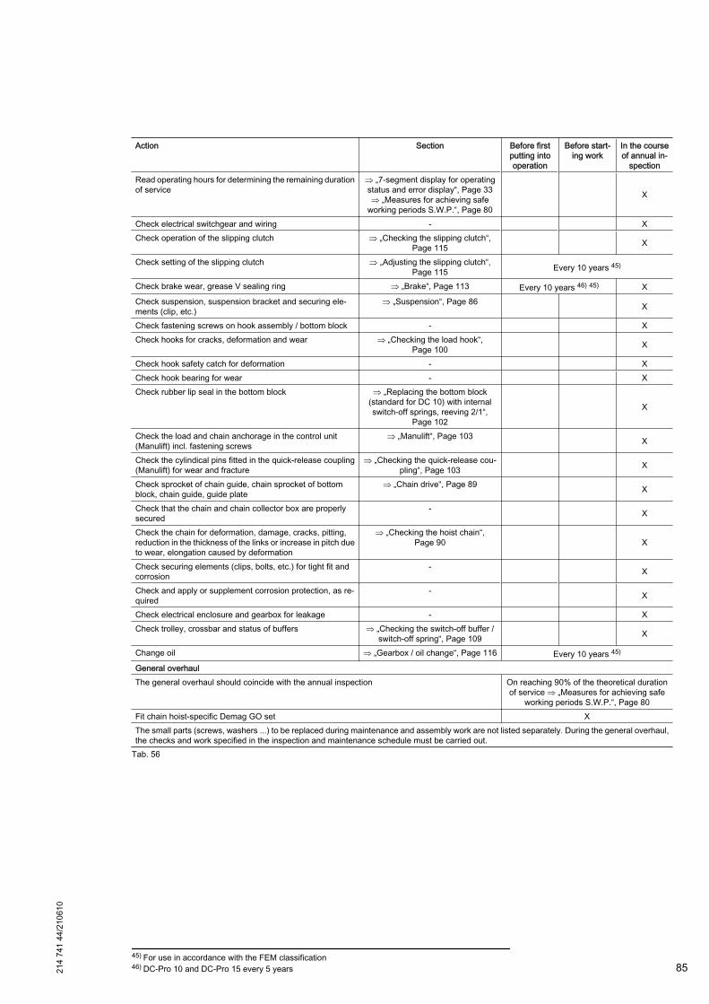
Action Section Before firstputting intooperation
Before start‐ing work
In the courseof annual in‐
spectionRead operating hours for determining the remaining durationof service
⇒ „7-segment display for operatingstatus and error display“, Page 33⇒ „Measures for achieving safe
working periods S.W.P.“, Page 80
X
Check electrical switchgear and wiring - XCheck operation of the slipping clutch ⇒ „Checking the slipping clutch“,
Page 115 X
Check setting of the slipping clutch ⇒ „Adjusting the slipping clutch“,Page 115 Every 10 years 45)
Check brake wear, grease V sealing ring ⇒ „Brake“, Page 113 Every 10 years 46) 45) XCheck suspension, suspension bracket and securing ele‐ments (clip, etc.)
⇒ „Suspension“, Page 86 X
Check fastening screws on hook assembly / bottom block - XCheck hooks for cracks, deformation and wear ⇒ „Checking the load hook“,
Page 100 X
Check hook safety catch for deformation - XCheck hook bearing for wear - XCheck rubber lip seal in the bottom block ⇒ „Replacing the bottom block
(standard for DC 10) with internalswitch-off springs, reeving 2/1“,
Page 102
X
Check the load and chain anchorage in the control unit(Manulift) incl. fastening screws
⇒ „Manulift“, Page 103 X
Check the cylindical pins fitted in the quick-release coupling(Manulift) for wear and fracture
⇒ „Checking the quick-release cou‐pling“, Page 103 X
Check sprocket of chain guide, chain sprocket of bottomblock, chain guide, guide plate
⇒ „Chain drive“, Page 89 X
Check that the chain and chain collector box are properlysecured
- X
Check the chain for deformation, damage, cracks, pitting,reduction in the thickness of the links or increase in pitch dueto wear, elongation caused by deformation
⇒ „Checking the hoist chain“,Page 90 X
Check securing elements (clips, bolts, etc.) for tight fit andcorrosion
- X
Check and apply or supplement corrosion protection, as re‐quired
- X
Check electrical enclosure and gearbox for leakage - XCheck trolley, crossbar and status of buffers ⇒ „Checking the switch-off buffer /
switch-off spring“, Page 109 X
Change oil ⇒ „Gearbox / oil change“, Page 116 Every 10 years 45)
General overhaulThe general overhaul should coincide with the annual inspection On reaching 90% of the theoretical duration
of service ⇒ „Measures for achieving safeworking periods S.W.P.“, Page 80
Fit chain hoist-specific Demag GO set XThe small parts (screws, washers ...) to be replaced during maintenance and assembly work are not listed separately. During the general overhaul,the checks and work specified in the inspection and maintenance schedule must be carried out.
Tab. 56
45) For use in accordance with the FEM classification46) DC-Pro 10 and DC-Pro 15 every 5 years21
4 74
1 44
/210
610
85

8.5 Maintenance work8.5.1 Suspension
If a check or inspection reveals that the dimensions are lower or higher than those specified due to wear or if crackscan be seen in these parts, they must be replaced at once.
Suspension bracket
Fig. 52
Chain hoist DC 1/ 2 / 5 DC 10 DC 15Suspension bracket short long short long longMin. dimension e suspen‐sion bracket [mm] 15,3 14,4 25,2 24,3 31,5
Tab. 57
Suspension ring
Fig. 53
Chain hoist DC 1/ 2 / 5 DC 10 DC 15Min. dimension e suspen‐sion ring turned 90°(chain hoist parallel to gird‐er)
[mm] 17,55 24,3 34,2
Tab. 58
8.5.2 Electrical equipment cover
Hold the electrical equipment cover while opening it. Do not let the electrical equipment cover fall into the fall pro‐tection.
When closing the electrical equipment cover, make sure that the fall protection does not cover the window or isjammed.
86 214
741
44/2
1061
0

8.5.3 Dismantling the chain collector box
Fig. 54
– Unscrew and disengage the service cover (1).
– Place the bag (2) with control cable on the top of the chain hoist.
– Disengage the spring (3) and place it in the recess in the chain collector box.
– Remove securing spring (4) from the pin (5) and pull out pin. While doing so, hold the chain collector.
– Deposit the chain collector box (6) on the ground.
8.5.4 Operating limit switches
8.5.4.1 Checking the operating limit switches
DANGER
Broken chains and load dropFrequent approaches of the emergency limit stop device may result in broken chains or load drops.
214
741
44/2
1061
0
87
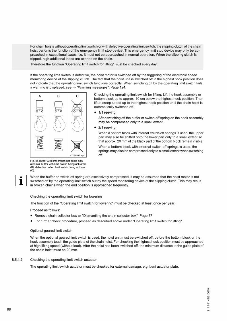
For chain hoists without operating limit switch or with defective operating limit switch, the slipping clutch of the chainhoist perfoms the function of the emergency limit stop device. This emergency limit stop device may only be ap‐proached in exceptional cases, i.e. it must not be approached in normal operation. When the slipping clutch istripped, high additional loads are exerted on the chain.Therefore the function "Operating limit switch for lifting" must be checked every day..
If the operating limit switch is defective, the hoist motor is switched off by the triggering of the electronic speedmonitoring device of the slipping clutch. The fact that the hoist unit is switched off in the highest hook position doesnot indicate that the operating limit switch functions correctly. When switching off by the operating limit switch fails,a warning is displayed, see ⇒ "Warning messages", Page 124.
Fig. 55 Buffer with limit switch not being actu‐ated (A), buffer with limit switch being actuated(B), defective buffer limit switch being actuated(C).
Checking the operating limit switch for lifting: Lift the hook assembly orbottom block up to approx. 10 cm below the highest hook position. Thenlift at creep speed up to the highest hook position until the chain hoist isautomatically switched off.● 1/1 reeving:
After switching off the buffer or switch-off spring on the hook assemblymay be compressed only to a small extent.
● 2/1 reeving:When a bottom block with internal switch-off springs is used, the upperpart may also be shifted onto the lower part only to a small extent sothat approx. 20 mm of the black part of the bottom block remain visible.When a bottom block with external switch-off springs is used, thesprings may also be compressed only to a small extent when switchingoff.
When the buffer or switch-off spring are excessively compressed, it may be assumed that the hoist motor is notswitched off by the operating limit switch but by the speed monitoring device of the slipping clutch. This may resultin broken chains when the end position is approached frequently.
Checking the operating limit switch for lowering
The function of the "Operating limit switch for lowering" must be checked at least once per year.
Proceed as follows:● Remove chain collector box ⇒ "Dismantling the chain collector box", Page 87● For further check procedure, proceed as described above under "Operating limit switch for lifting".
Optional geared limit switch
When the optional geared limit switch is used, the hoist unit must be switched off, before the bottom block or thehook assembly touch the guide plate of the chain hoist. For checking the highest hook position must be approachedat high lifting speed (without load). After the hoist has been switched off, the minimum distance to the guide plate ofthe chain hoist must be 20 mm.
8.5.4.2 Checking the operating limit switch actuator
The operating limit switch actuator must be checked for external damage, e.g. bent actuator plate.
88 214
741
44/2
1061
0
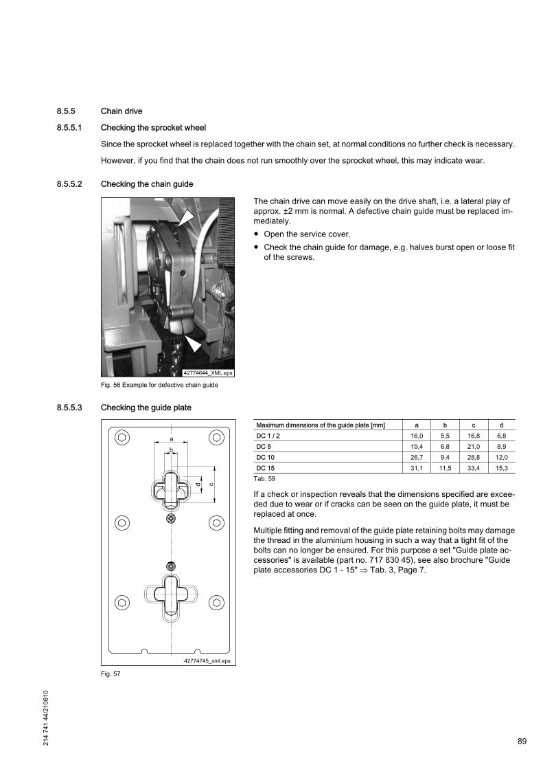
8.5.5 Chain drive
8.5.5.1 Checking the sprocket wheel
Since the sprocket wheel is replaced together with the chain set, at normal conditions no further check is necessary.
However, if you find that the chain does not run smoothly over the sprocket wheel, this may indicate wear.
8.5.5.2 Checking the chain guide
Fig. 56 Example for defective chain guide
The chain drive can move easily on the drive shaft, i.e. a lateral play ofapprox. ±2 mm is normal. A defective chain guide must be replaced im‐mediately.● Open the service cover.● Check the chain guide for damage, e.g. halves burst open or loose fit
of the screws.
8.5.5.3 Checking the guide plate
Fig. 57
Maximum dimensions of the guide plate [mm] a b c dDC 1 / 2 16,0 5,5 16,8 6,8DC 5 19,4 6,8 21,0 8,9DC 10 26,7 9,4 28,8 12,0DC 15 31,1 11,5 33,4 15,3
Tab. 59
If a check or inspection reveals that the dimensions specified are excee‐ded due to wear or if cracks can be seen on the guide plate, it must bereplaced at once.
Multiple fitting and removal of the guide plate retaining bolts may damagethe thread in the aluminium housing in such a way that a tight fit of thebolts can no longer be ensured. For this purpose a set "Guide plate ac‐cessories" is available (part no. 717 830 45), see also brochure "Guideplate accessories DC 1 - 15" ⇒ Tab. 3, Page 7.
214
741
44/2
1061
0
89
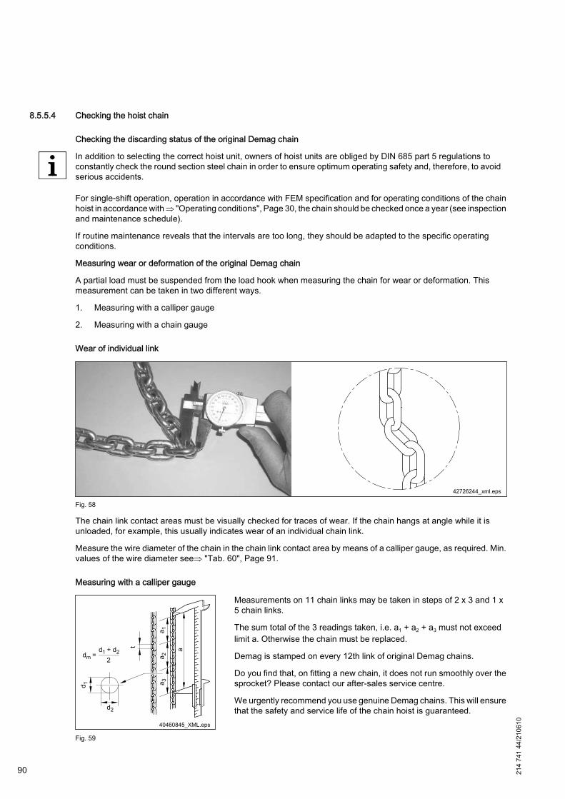
8.5.5.4 Checking the hoist chain
Checking the discarding status of the original Demag chain
In addition to selecting the correct hoist unit, owners of hoist units are obliged by DIN 685 part 5 regulations toconstantly check the round section steel chain in order to ensure optimum operating safety and, therefore, to avoidserious accidents.
For single-shift operation, operation in accordance with FEM specification and for operating conditions of the chainhoist in accordance with ⇒ "Operating conditions", Page 30, the chain should be checked once a year (see inspectionand maintenance schedule).
If routine maintenance reveals that the intervals are too long, they should be adapted to the specific operatingconditions.
Measuring wear or deformation of the original Demag chain
A partial load must be suspended from the load hook when measuring the chain for wear or deformation. Thismeasurement can be taken in two different ways.
1. Measuring with a calliper gauge
2. Measuring with a chain gauge
Wear of individual link
Fig. 58
The chain link contact areas must be visually checked for traces of wear. If the chain hangs at angle while it isunloaded, for example, this usually indicates wear of an individual chain link.
Measure the wire diameter of the chain in the chain link contact area by means of a calliper gauge, as required. Min.values of the wire diameter see⇒ "Tab. 60", Page 91.
Measuring with a calliper gauge
Fig. 59
Measurements on 11 chain links may be taken in steps of 2 x 3 and 1 x5 chain links.
The sum total of the 3 readings taken, i.e. a1 + a2 + a3 must not exceedlimit a. Otherwise the chain must be replaced.
Demag is stamped on every 12th link of original Demag chains.
Do you find that, on fitting a new chain, it does not run smoothly over thesprocket? Please contact our after-sales service centre.
We urgently recommend you use genuine Demag chains. This will ensurethat the safety and service life of the chain hoist is guaranteed.
90 214
741
44/2
1061
0

Demag chain hoist DC-Pro 1 / 2 DC-Pro 5 DC-Pro 10 DC-Pro 15Chain designation d x t 4,2 x 12,2 5,3 x 15,2 7,4 x 21,2 8,7 x 24,2Limit dimensions according to DIN 685 part 5 Measurement over 11 chain links outside, max. dimension = a 1 + a 2 + a 3 144,7 mm 180,3 mm 253 mm 289 mm
Overall length of 1 chain link measured on the inside, max. dimension t 12,8 mm 15,9 mm 22,4 mm 25,5 mmMeasurement of the chain link diameter, min. dimension dm = 0,9 x d 3,8 mm 4,8 mm 6,7 mm 7,8 mm
Tab. 60
Measuring with a chain gauge
Fig. 60
A DC / DK / PK new chainB PK old chain1 The discarding status has not yet been reached.
It is not yet necessary to replace the chain. It isnecessary to replace the chain, when the meas‐
uring pin can no longer move into the 11th chainlink.
2 Measuring pin3 11. th chain link; The discarding status has been
reached. The chain must be replaced.
Designation Part no.: Weight [kg]Chain gauge 836 025 44 0,540
Tab. 61
214
741
44/2
1061
0
91
8.5.5.5 Scope of supply chain set
On reaching the permissible limit of chain wear the chain set must be replaced (for determining the wear limit of thechain ⇒ "Checking the hoist chain", Page 90.
When a new RDC standard chain is ordered, a chain set is always supplied.
The chain set includes the following parts:● Chain,● Sprocket wheel,● Chain guide with plate and cap,● Chain guide plate,● Buffers for upper and lower hook position,● Demag chain grease tube,● Retaining ring.
The chain guide is pre-assembled, the chain is already fitted in the chain guide.
92 214
741
44/2
1061
0
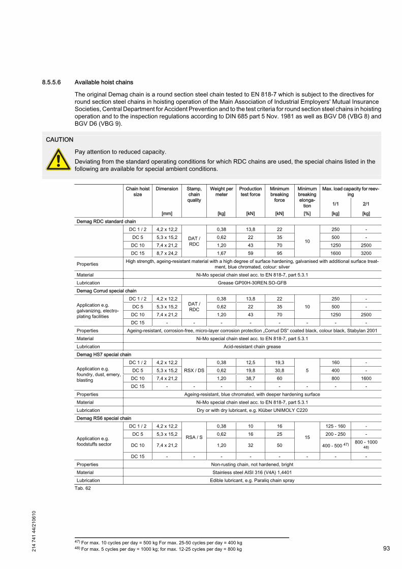
8.5.5.6 Available hoist chains
The original Demag chain is a round section steel chain tested to EN 818-7 which is subject to the directives forround section steel chains in hoisting operation of the Main Association of Industrial Employers' Mutual InsuranceSocieties, Central Department for Accident Prevention and to the test criteria for round section steel chains in hoistingoperation and to the inspection regulations according to DIN 685 part 5 Nov. 1981 as well as BGV D8 (VBG 8) andBGV D6 (VBG 9).
CAUTION
Pay attention to reduced capacity.Deviating from the standard operating conditions for which RDC chains are used, the special chains listed in thefollowing are available for special ambient conditions.
Chain hoistsize
Dimension Stamp,chainquality
Weight permeter
Productiontest force
Minimumbreaking
force
Minimumbreakingelonga‐
tion
Max. load capacity for reev‐ing
1/1 2/1
[mm] [kg] [kN] [kN] [%] [kg] [kg]Demag RDC standard chain
DC 1 / 2 4,2 x 12,2
DAT /RDC
0,38 13,8 22
10
250 -DC 5 5,3 x 15,2 0,62 22 35 500 -
DC 10 7,4 x 21,2 1,20 43 70 1250 2500DC 15 8,7 x 24,2 1,67 59 95 1600 3200
Properties High strength, ageing-resistant material with a high degree of surface hardening, galvanised with additional surface treat‐ment, blue chromated, colour: silver
Material Ni-Mo special chain steel acc. to EN 818-7, part 5.3.1Lubrication Grease GP00H-30REN.SO-GFBDemag Corrud special chain
Application e.g.galvanizing, electro‐plating facilities
DC 1 / 2 4,2 x 12,2DAT /RDC
0,38 13,8 2210
250 -DC 5 5,3 x 15,2 0,62 22 35 500 -
DC 10 7,4 x 21,2 1,20 43 70 1250 2500DC 15 - - - - - - - -
Properties Ageing-resistant, corrosion-free, micro-layer corrosion protection „Corrud DS“ coated black, colour black, Stabylan 2001Material Ni-Mo special chain steel acc. to EN 818-7, part 5.3.1Lubrication Acid-resistant chain greaseDemag HS7 special chain
Application e.g.foundry, dust, emery,blasting
DC 1 / 2 4,2 x 12,2RSX / DS
0,38 12,5 19,35
160 -DC 5 5,3 x 15,2 0,62 19,8 30,8 400 -
DC 10 7,4 x 21,2 1,20 38,7 60 800 1600DC 15 - - - - - - - -
Properties Ageing-resistant, blue chromated, with deeper hardening surfaceMaterial Ni-Mo special chain steel acc. to EN 818-7, part 5.3.1Lubrication Dry or with dry lubricant, e.g. Klüber UNIMOLY C220Demag RS6 special chain
Application e.g.foodstuffs sector
DC 1 / 2 4,2 x 12,2
RSA / S
0,38 10 16
15
125 - 160 -DC 5 5,3 x 15,2 0,62 16 25 200 - 250 -
DC 10 7,4 x 21,2 1,20 32 50 400 - 500 47) 800 - 100048)
DC 15 - - - - - - - -Properties Non-rusting chain, not hardened, brightMaterial Stainless steel AISI 316 (V4A) 1,4401Lubrication Edible lubricant, e.g. Paraliq chain spray
Tab. 62
47) For max. 10 cycles per day = 500 kg For max. 25-50 cycles per day = 400 kg48) For max. 5 cycles per day = 1000 kg; for max. 12-25 cycles per day = 800 kg21
4 74
1 44
/210
610
93
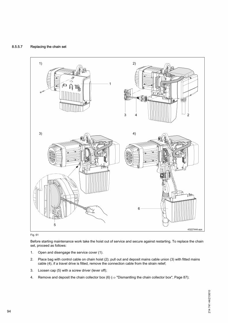
8.5.5.7 Replacing the chain set
Fig. 61
Before starting maintenance work take the hoist out of service and secure against restarting. To replace the chainset, proceed as follows:
1. Open and disengage the service cover (1).
2. Place bag with control cable on chain hoist (2); pull out and deposit mains cable union (3) with fitted mainscable (4), if a travel drive is fitted, remove the connection cable from the strain relief;
3. Loosen cap (5) with a screw driver (lever off);
4. Remove and deposit the chain collector box (6) (⇒ "Dismantling the chain collector box", Page 87);
94 214
741
44/2
1061
0
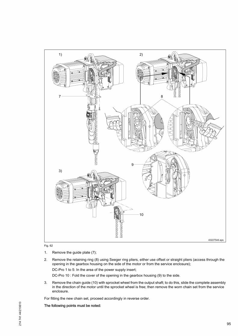
Fig. 62
1. Remove the guide plate (7);
2. Remove the retaining ring (8) using Seeger ring pliers, either use offset or straight pliers (access through theopening in the gearbox housing on the side of the motor or from the service enclosure);DC-Pro 1 to 5: In the area of the power supply insert;DC-Pro 10 : Fold the cover of the opening in the gearbox housing (9) to the side.
3. Remove the chain guide (10) with sprocket wheel from the output shaft; to do this, slide the complete assemblyin the direction of the motor until the sprocket wheel is free; then remove the worn chain set from the serviceenclosure.
For fitting the new chain set, proceed accordingly in reverse order.
The following points must be noted:
214
741
44/2
1061
0
95

Chain hoist with geared limit switch
Fig. 63
A) Chain guide for DC 10 without geared limit switch B) Chain guide for DC 10 with geared limit switchTab. 63
When the chain hoist is equipped with a geared limit switch, the chain guide has a larger bore hole.
See also ⇒ "Chain drive", Page 132
Spacer rings for the output shaft
Fig. 64
● When fitting the chain guide, the complete number of spacer rings mustbe fitted on the output shaft.
Item Designation1 Cap2 Retaining ring3 Spacer ring DC-Pro 15 14 Chain guide
5 Spacer ring
DC-Pro 1 / 2 3DC-Pro 5 1DC-Pro 10 2DC-Pro 15 2
Tab. 64
Before you slide on the chain sprocket, lubricate the spliningof the output shaft with Molykote or similar.
Fitting the retaining ring
Fig. 65
● The stamped burr of the retaining ring (1) must face the motor. Correctfit of the retaining ring is ensured when it can be easily turned on theoutput shaft after assembly.
DANGER
Broken chains and load dropAn incorrectly fitted chain may lead to broken chains or loaddrops.When fitting the chain, it must be ensured that the chain isintroduced in the same position and orientation.The chain must operate without any twist.
96 214
741
44/2
1061
0

Fitting the chain anchorage for DC 10, 2/1 reeving
Fig. 66
● Fit the chain anchorage before bolting the guide plates into position for DC-Pro 10 with 2/1 reeving. Bolt the chainanchorage halves (1) together (Fig. A).
● Insert the bolted chain anchorage into the opening of the gearbox housing (Fig. B).● Fit the pins (2) (the pins are secured by the fitted guide plates).
Fitting the chain anchorage for DC 15, 2/1 reeving
Fig. 67
Fit the chain anchorage before bolting the guide plate (4) into position forDC-Pro 15 with 2/1 reeving.● When removing the chain anchorage push the two pins (1) out of the
bore holes only to such an extent that the chain anchorage can beremoved.
● Put the chain end between the two chain anchorage halves (3) andbolt them together with a tightening torque of 25 Nm.
● Insert the bolted chain anchorage into the opening of the gearboxhousing.
● Completely push back the two pins (1) into the bore holes (the pins aresecured by the fitted guide plate).
Item Designation1 Chain anchorage pin2 Hex. socket head screw of chain anchorage halves3 Chain anchorage half4 Guide plate5 Hex. socket head screw of guide plate
Tab. 65
214
741
44/2
1061
0
97
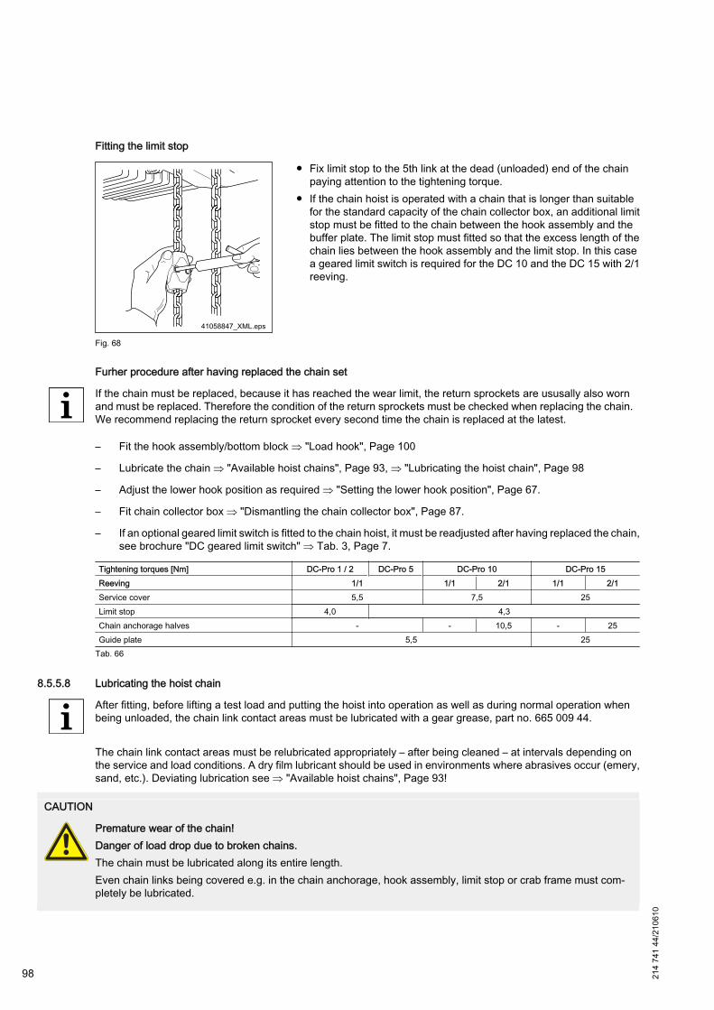
Fitting the limit stop
Fig. 68
● Fix limit stop to the 5th link at the dead (unloaded) end of the chainpaying attention to the tightening torque.
● If the chain hoist is operated with a chain that is longer than suitablefor the standard capacity of the chain collector box, an additional limitstop must be fitted to the chain between the hook assembly and thebuffer plate. The limit stop must fitted so that the excess length of thechain lies between the hook assembly and the limit stop. In this casea geared limit switch is required for the DC 10 and the DC 15 with 2/1reeving.
Furher procedure after having replaced the chain set
If the chain must be replaced, because it has reached the wear limit, the return sprockets are ususally also wornand must be replaced. Therefore the condition of the return sprockets must be checked when replacing the chain.We recommend replacing the return sprocket every second time the chain is replaced at the latest.
– Fit the hook assembly/bottom block ⇒ "Load hook", Page 100
– Lubricate the chain ⇒ "Available hoist chains", Page 93, ⇒ "Lubricating the hoist chain", Page 98
– Adjust the lower hook position as required ⇒ "Setting the lower hook position", Page 67.
– Fit chain collector box ⇒ "Dismantling the chain collector box", Page 87.
– If an optional geared limit switch is fitted to the chain hoist, it must be readjusted after having replaced the chain,see brochure "DC geared limit switch" ⇒ Tab. 3, Page 7.
Tightening torques [Nm] DC-Pro 1 / 2 DC-Pro 5 DC-Pro 10 DC-Pro 15Reeving 1/1 1/1 2/1 1/1 2/1Service cover 5,5 7,5 25Limit stop 4,0 4,3Chain anchorage halves - - 10,5 - 25Guide plate 5,5 25
Tab. 66
8.5.5.8 Lubricating the hoist chain
After fitting, before lifting a test load and putting the hoist into operation as well as during normal operation whenbeing unloaded, the chain link contact areas must be lubricated with a gear grease, part no. 665 009 44.
The chain link contact areas must be relubricated appropriately – after being cleaned – at intervals depending onthe service and load conditions. A dry film lubricant should be used in environments where abrasives occur (emery,sand, etc.). Deviating lubrication see ⇒ "Available hoist chains", Page 93!
CAUTION
Premature wear of the chain!Danger of load drop due to broken chains.The chain must be lubricated along its entire length.Even chain links being covered e.g. in the chain anchorage, hook assembly, limit stop or crab frame must com‐pletely be lubricated.
98 214
741
44/2
1061
0
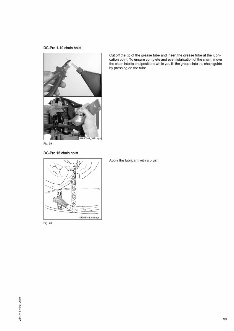
DC-Pro 1-10 chain hoist
Fig. 69
Cut off the tip of the grease tube and insert the grease tube at the lubri‐cation point. To ensure complete and even lubrication of the chain, movethe chain into its end positions while you fill the grease into the chain guideby pressing on the tube.
DC-Pro 15 chain hoist
Fig. 70
Apply the lubricant with a brush.
214
741
44/2
1061
0
99

8.5.6 Load hook
8.5.6.1 Checking the load hook
Fig. 71
SWL [kg] 125 250 500 1250 2500 1600 3200Chain hoist DC-Pro 1 2 5 10 15Reeving 1/1 2/1 1/1 2/1Load hook Type V 2 V 3 V 4 V 5 V 5 V 6
Dimensions [mm]
a1 30 36 43 50 50 56
a2nom 49) 25,3 30,5 36 39 43,7 49
a2max 27,83 33,55 39,6 42,9 48,07 53,9
b1 13 19 22 29 29 30h1 22 27,5 33,5 44 44 55
h2nom 50) 18 21,5 26 34 34 38
h2min 17,1 20,42 24,7 32,3 32.3 36,1
L2 22 30 36 24 45 56L4 86 109 110 154 159 187d1 19,8 23,8 31,8 38 41.8 49.8
Max. test force [kN] 8 16 25 50 50 65Max. hook force [kN] 16 32 50 100 100 130
Tab. 67
8.5.6.2 Checking the return sprocket
The return sprocket must be checked for smooth turnability every month. For this purpose it may be necessary toremove fixed crossbars from the bottom block.
Check whether the bottom block moves correctly when lifting and lowering. Jerky movements of the bottom blockindicate wear.
49) Permissible deviation +10%50) Permissible deviation -5%100 21
4 74
1 44
/210
610
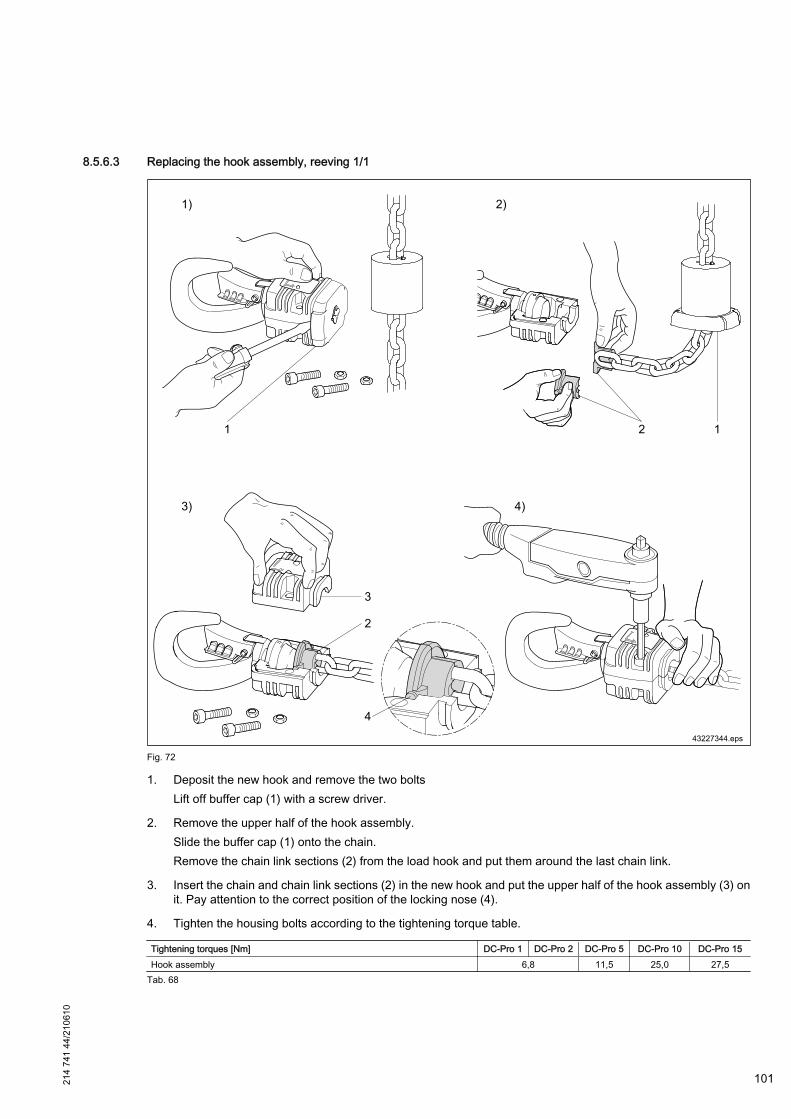
8.5.6.3 Replacing the hook assembly, reeving 1/1
Fig. 72
1. Deposit the new hook and remove the two boltsLift off buffer cap (1) with a screw driver.
2. Remove the upper half of the hook assembly.Slide the buffer cap (1) onto the chain.Remove the chain link sections (2) from the load hook and put them around the last chain link.
3. Insert the chain and chain link sections (2) in the new hook and put the upper half of the hook assembly (3) onit. Pay attention to the correct position of the locking nose (4).
4. Tighten the housing bolts according to the tightening torque table.
Tightening torques [Nm] DC-Pro 1 DC-Pro 2 DC-Pro 5 DC-Pro 10 DC-Pro 15Hook assembly 6,8 11,5 25,0 27,5
Tab. 68
214
741
44/2
1061
0
101

8.5.6.4 Replacing the bottom block (standard for DC 10) with internal switch-off springs, reeving 2/1
Fig. 73
1. Remove the guide halves (1) (four M 6 screws);
2. Loosen the clamping screws (2) of the bottom block and remove the bottom block;
3. Introduce the chain into the new bottom block in the same position and orientation (chain must operate withoutany twist);
4. Assemble the bottom block and tighten the screws (2) with 52 Nm;
5. Check the correct fit of the four switch-off springs (3) in the new bottom block halves (4);
6. Fit the new guide halves (1) and tighten the screws (5) with 5,5 Nm;
7. Apply load capacity plate;
8. Perform function check (run against operating limit switches and check 7-segment display).
Tightening torques [Nm] DC-Pro 10
Bottom block with internal switch-off springsBottom block halves 52,0Guide halves 5,5
Tab. 69
Bottom block from approx. 09/2009
Fig. 74
From approx. 09/2009 the bottom block is provided with rubber lips (1) inthe area of the chain entry. During the annual inspection the rubber lipmust be checked for wear and correct fit.
102 214
741
44/2
1061
0
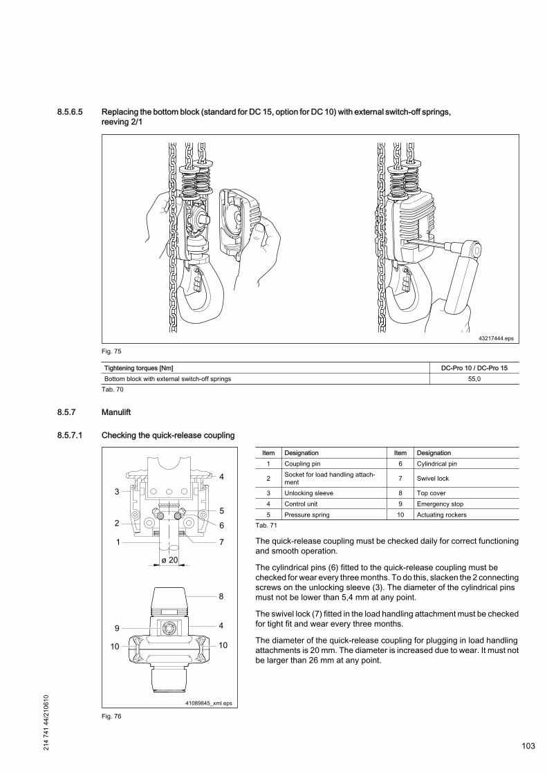
8.5.6.5 Replacing the bottom block (standard for DC 15, option for DC 10) with external switch-off springs,reeving 2/1
Fig. 75
Tightening torques [Nm] DC-Pro 10 / DC-Pro 15Bottom block with external switch-off springs 55,0
Tab. 70
8.5.7 Manulift
8.5.7.1 Checking the quick-release coupling
Fig. 76
Item Designation Item Designation1 Coupling pin 6 Cylindrical pin
2 Socket for load handling attach‐ment 7 Swivel lock
3 Unlocking sleeve 8 Top cover4 Control unit 9 Emergency stop5 Pressure spring 10 Actuating rockers
Tab. 71
The quick-release coupling must be checked daily for correct functioningand smooth operation.
The cylindrical pins (6) fitted to the quick-release coupling must bechecked for wear every three months. To do this, slacken the 2 connectingscrews on the unlocking sleeve (3). The diameter of the cylindrical pinsmust not be lower than 5,4 mm at any point.
The swivel lock (7) fitted in the load handling attachment must be checkedfor tight fit and wear every three months.
The diameter of the quick-release coupling for plugging in load handlingattachments is 20 mm. The diameter is increased due to wear. It must notbe larger than 26 mm at any point.
214
741
44/2
1061
0
103
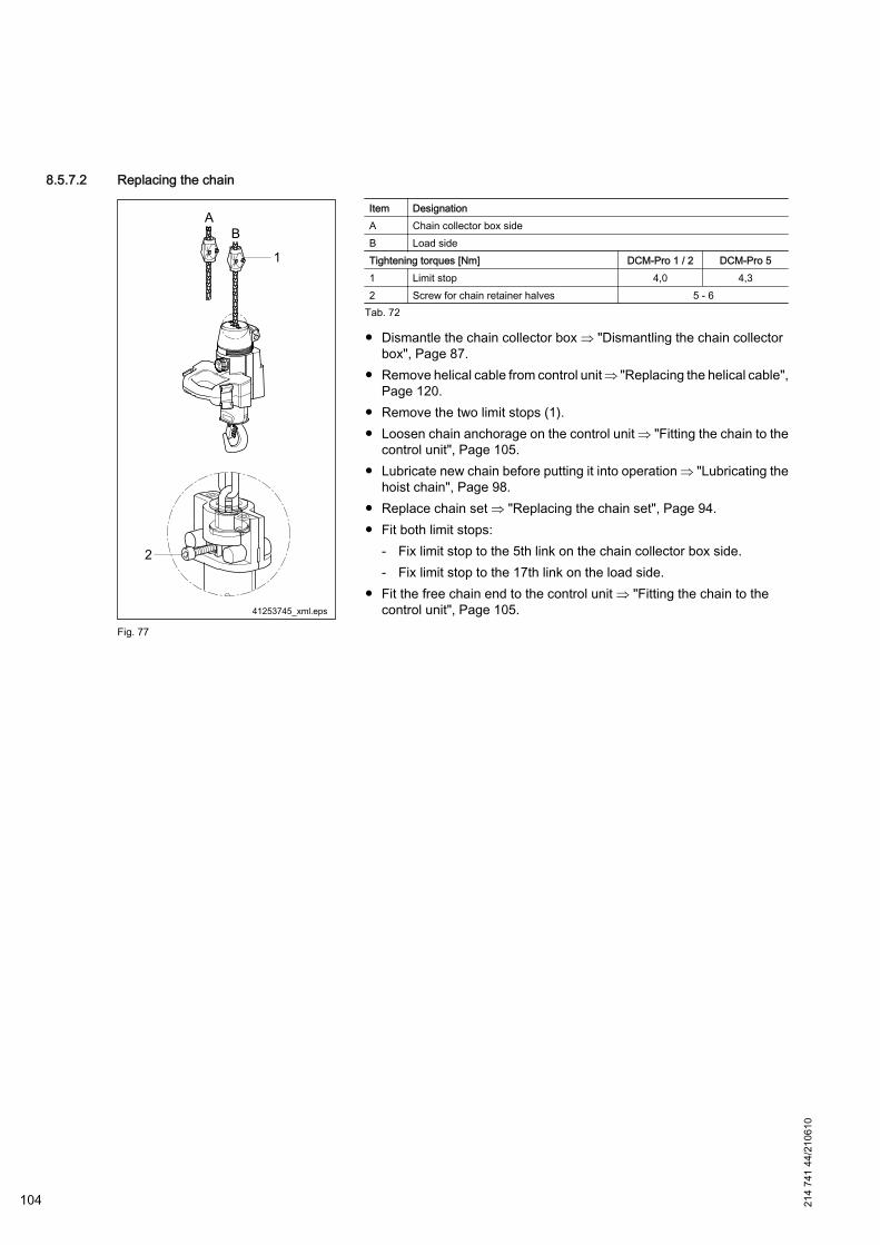
8.5.7.2 Replacing the chain
Fig. 77
Item DesignationA Chain collector box sideB Load sideTightening torques [Nm] DCM-Pro 1 / 2 DCM-Pro 51 Limit stop 4,0 4,32 Screw for chain retainer halves 5 - 6
Tab. 72
● Dismantle the chain collector box ⇒ "Dismantling the chain collectorbox", Page 87.
● Remove helical cable from control unit ⇒ "Replacing the helical cable",Page 120.
● Remove the two limit stops (1).● Loosen chain anchorage on the control unit ⇒ "Fitting the chain to the
control unit", Page 105.● Lubricate new chain before putting it into operation ⇒ "Lubricating the
hoist chain", Page 98.● Replace chain set ⇒ "Replacing the chain set", Page 94.● Fit both limit stops:
- Fix limit stop to the 5th link on the chain collector box side.- Fix limit stop to the 17th link on the load side.
● Fit the free chain end to the control unit ⇒ "Fitting the chain to thecontrol unit", Page 105.
104 214
741
44/2
1061
0
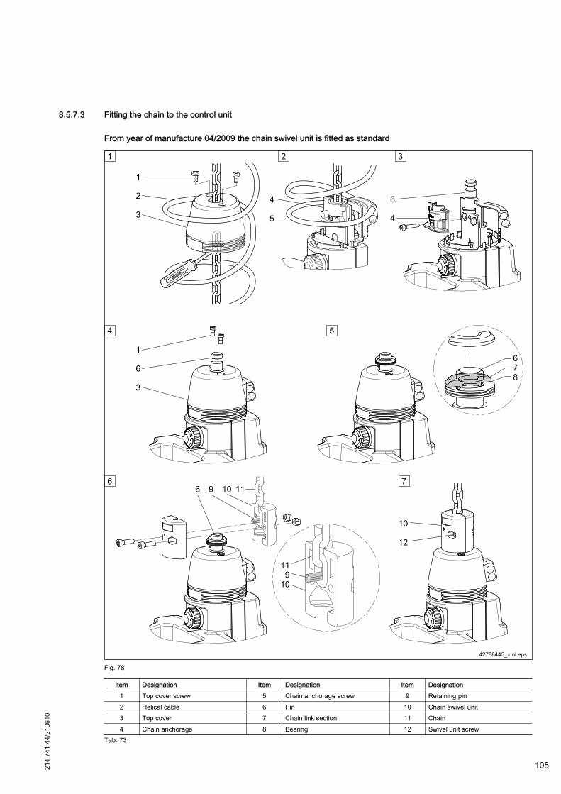
8.5.7.3 Fitting the chain to the control unit
From year of manufacture 04/2009 the chain swivel unit is fitted as standard
Fig. 78
Item Designation Item Designation Item Designation1 Top cover screw 5 Chain anchorage screw 9 Retaining pin2 Helical cable 6 Pin 10 Chain swivel unit3 Top cover 7 Chain link section 11 Chain4 Chain anchorage 8 Bearing 12 Swivel unit screw
Tab. 73
214
741
44/2
1061
0
105

Deposit the Manulift so that the chain and helical cable are unloaded.
Disassembly:
1. Push helical cable (2) to the side and loosen the screws (1) of the top cover (3). Slide top cover (3) off the chainanchorage (4) and secure it against slipping.
2. Loosen screw (5) of the chain anchorage (4). Open the chain anchorage (4) and remove the chain link sectionsand the chain.
Assembly:
3. Insert pin (6) in the chain anchorage (4) and bolt the two chain anchorage halves (4) together with a tighteningtorque of 5 - 6 Nm.
4. Slide top cover (3) over the pin (6) and tighten the top cover screws (1) with a tightening torque of 3 Nm.
5. Fit bearing (8) and the chain link sections (7) on pin (6) in the correct sequence.
DANGER
Load dropIncorrect assembly may result in load drops.During assembly it must be ensured1. That the chain link sections (7) are positioned in bearing (8) with their collar. Grease the bearing and bearing
seat.
6. Insert retaining pin (9) in chain (11) and put the swivel unit half (10) around pin (6).
DANGER
Load dropIncorrect assembly may result in load drops.During assembly it must be ensured1. that retaining pin (9) is correctly fitted when the swivel unit is assembled.
7. Close swivel unit halves (10) and tighten screws (12) with the correct tightening torque:Chain 4,2 x 12,2 ⇒ 6,8 Nm;Chain 5,3 x 15,2 ⇒ 9,5 Nm.
Until year of manufacture 03/2009
Fig. 79
1. Loosen cap screws (1), slide cap (2) upwards and secure against dropping (e.g. with a screwdriver).Pull the new chain through cap (2) before fitting.
106 214
741
44/2
1061
0
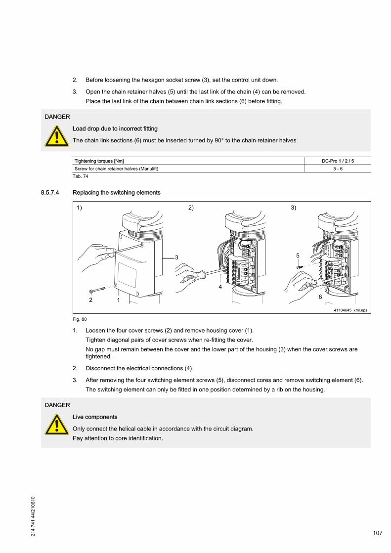
2. Before loosening the hexagon socket screw (3), set the control unit down.
3. Open the chain retainer halves (5) until the last link of the chain (4) can be removed.Place the last link of the chain between chain link sections (6) before fitting.
DANGER
Load drop due to incorrect fitting
The chain link sections (6) must be inserted turned by 90° to the chain retainer halves.
Tightening torques [Nm] DC-Pro 1 / 2 / 5Screw for chain retainer halves (Manulift) 5 - 6
Tab. 74
8.5.7.4 Replacing the switching elements
Fig. 80
1. Loosen the four cover screws (2) and remove housing cover (1).Tighten diagonal pairs of cover screws when re-fitting the cover.No gap must remain between the cover and the lower part of the housing (3) when the cover screws aretightened.
2. Disconnect the electrical connections (4).
3. After removing the four switching element screws (5), disconnect cores and remove switching element (6).The switching element can only be fitted in one position determined by a rib on the housing.
DANGER
Live components
Only connect the helical cable in accordance with the circuit diagram.Pay attention to core identification.
214
741
44/2
1061
0
107

8.5.7.5 Replacing the gearbox
Fig. 81
1. Loosen cap screws (1), slide cap (2) upwards and secure against dropping (e.g. with a screwdriver).
2. Loosen the four screws (4) and lift off upper part of housing (3).
3. After removing the bearing block screws (5), pull upwards the complete gear mechanism with rocker switches(6).
4. Turn the shaft (10) by 90° in relation to the bearing block (7) and remove it.Fit the shaft (10) with the bevel gear (8) into the bearing block (7) as illustrated.Ensure that the bevel gears mesh properly with their counterpart gears.
5. Pull the bevel gear (8) off the shaft (10).When fitting the bevel gear (8) to the shaft, ensure that it is pushed on until it comes up against the stop.Pay attention to the correct position in relation to the lever (9).
6. The emergency-stop button (11) must not be pressed when the two halves of the housing are fitted together.
8.5.7.6 Load handling attachments
Load handling attachments must be checked depending on their frequency of use:● The smooth locking and unlocking operation of the tongs locking mechanism must be checked daily. Keep the
mechanism clean (but do not oil).● Regularly check the smooth operation of the pantograph hinges. Clean and oil the hinges as necessary. Affected
parts must be replaced immediately if cracks, deformation, wear of hinge pins (hinge play approx. 1,5 mm) andjaws are detected.
● Belt slings must be checked once a week if they are regularly used, or before being used again if they have notbeen used for a long period. During these checks, the fabric should be examined for brittleness, damage by
108 214
741
44/2
1061
0

chemicals or stretching, and for deformation caused by heat; the general condition of the end fittings should alsobe checked.
8.5.8 Buffers
8.5.8.1 Checking the switch-off buffer / switch-off spring
Fig. 82
1. Buffer wear:In the course of annual inspection visually check the buffers. Check for damage and cracks.
2. Missing buffer plate:When fitting new buffers, pay attention to the correct fitting sequence of the component parts ( see also⇒ "Buffer design", Page 110), e.g. a missing buffer plate leads to premature wear of the buffers.
3. Wear of external switch-off spring:In the course of annual inspection visually check the external switch-off springs. Check the sleeves of thesprings for damage and cracks. The individual windings of the springs must not be shifted above each other.
214
741
44/2
1061
0
109
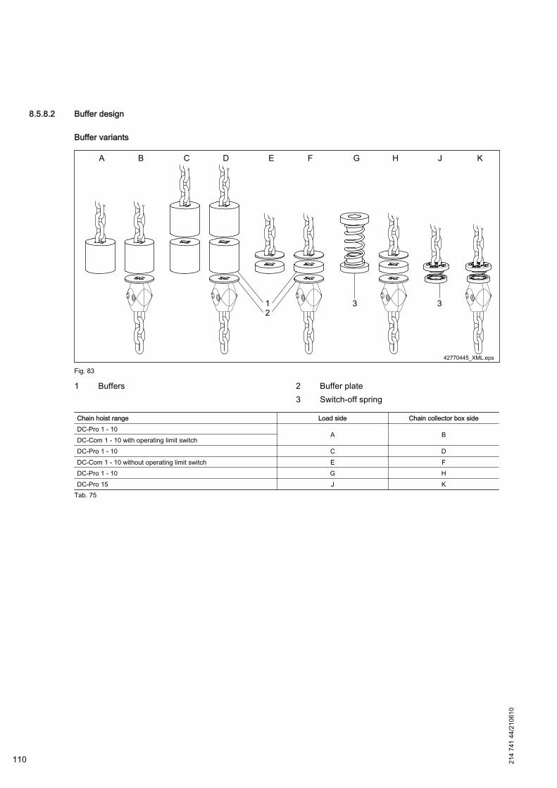
8.5.8.2 Buffer design
Buffer variants
Fig. 83
1 Buffers 2 Buffer plate3 Switch-off spring
Chain hoist range Load side Chain collector box sideDC-Pro 1 - 10
A BDC-Com 1 - 10 with operating limit switchDC-Pro 1 - 10 C DDC-Com 1 - 10 without operating limit switch E FDC-Pro 1 - 10 G HDC-Pro 15 J K
Tab. 75
110 214
741
44/2
1061
0
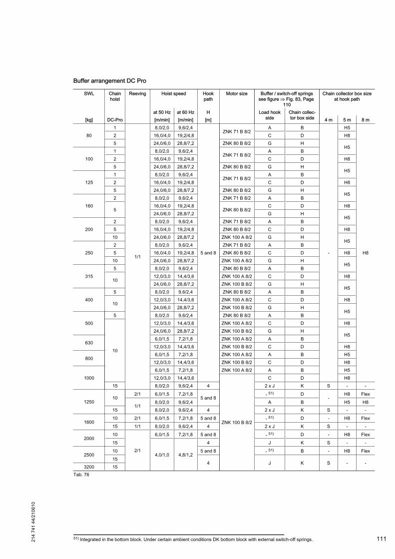
Buffer arrangement DC Pro
SWL Chainhoist
Reeving Hoist speed Hookpath
Motor size Buffer / switch-off springssee figure ⇒ Fig. 83, Page
110
Chain collector box sizeat hook path
at 50 Hz at 60 Hz H Load hookside
Chain collec‐tor box side[kg] DC-Pro [m/min] [m/min] [m] 4 m 5 m 8 m
801
1/1
8,0/2,0 9,6/2,4
5 and 8
ZNK 71 B 8/2A B
-
H5
H8
2 16,0/4,0 19,2/4,8 C D H85 24,0/6,0 28,8/7,2 ZNK 80 B 8/2 G H
H5
1001 8,0/2,0 9,6/2,4
ZNK 71 B 8/2A B
2 16,0/4,0 19,2/4,8 C D H85 24,0/6,0 28,8/7,2 ZNK 80 B 8/2 G H
H5
1251 8,0/2,0 9,6/2,4
ZNK 71 B 8/2A B
2 16,0/4,0 19,2/4,8 C D H85 24,0/6,0 28,8/7,2 ZNK 80 B 8/2 G H
H5
1602 8,0/2,0 9,6/2,4 ZNK 71 B 8/2 A B
516,0/4,0 19,2/4,8
ZNK 80 B 8/2C D H8
24,0/6,0 28,8/7,2 G HH5
2002 8,0/2,0 9,6/2,4 ZNK 71 B 8/2 A B5 16,0/4,0 19,2/4,8 ZNK 80 B 8/2 C D H810 24,0/6,0 28,8/7,2 ZNK 100 A 8/2 G H
H5
2502 8,0/2,0 9,6/2,4 ZNK 71 B 8/2 A B5 16,0/4,0 19,2/4,8 ZNK 80 B 8/2 C D H810 24,0/6,0 28,8/7,2 ZNK 100 A 8/2 G H
H5
3155 8,0/2,0 9,6/2,4 ZNK 80 B 8/2 A B
1012,0/3,0 14,4/3,6 ZNK 100 A 8/2 C D H824,0/6,0 28,8/7,2 ZNK 100 B 8/2 G H
H5
4005 8,0/2,0 9,6/2,4 ZNK 80 B 8/2 A B
1012,0/3,0 14,4/3,6 ZNK 100 A 8/2 C D H824,0/6,0 28,8/7,2 ZNK 100 B 8/2 G H
H5
5005 8,0/2,0 9,6/2,4 ZNK 80 B 8/2 A B
10
12,0/3,0 14,4/3,6 ZNK 100 A 8/2 C D H824,0/6,0 28,8/7,2 ZNK 100 B 8/2 G H
H5630
6,0/1,5 7,2/1,8 ZNK 100 A 8/2 A B12,0/3,0 14,4/3,6 ZNK 100 B 8/2 C D H8
8006,0/1,5 7,2/1,8 ZNK 100 A 8/2 A B H512,0/3,0 14,4/3,6 ZNK 100 B 8/2 C D H8
10006,0/1,5 7,2/1,8 ZNK 100 A 8/2 A B H512,0/3,0 14,4/3,6
ZNK 100 B 8/2
C D H815 8,0/2,0 9,6/2,4 4 2 x J K S - -
125010
2/1 6,0/1,5 7,2/1,85 and 8
- 51) D-
H8 Flex
1/18,0/2,0 9,6/2,4 A B H5 H8
15 8,0/2,0 9,6/2,4 4 2 x J K S - -
160010 2/1 6,0/1,5 7,2/1,8 5 and 8 - 51) D - H8 Flex15 1/1 8,0/2,0 9,6/2,4 4 2 x J K S - -
200010
2/1
6,0/1,5 7,2/1,8 5 and 8 - 51) D - H8 Flex
15
4,0/1,0 4,8/1,2
4 J K S - -
250010 5 and 8 - 51) B - H8 Flex15
4 J K S - -3200 15
Tab. 76
51) Integrated in the bottom block. Under certain ambient conditions DK bottom block with external switch-off springs.214
741
44/2
1061
0
111
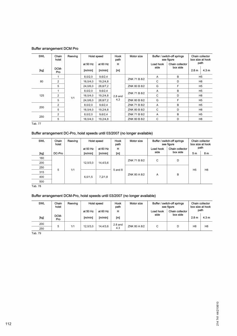
Buffer arrangement DCM Pro
SWL Chainhoist
Reeving Hoist speed Hookpath
Motor size Buffer / switch-off springssee figure
Chain collectorbox size at hook
pathat 50 Hz at 60 Hz H Load hookside
Chain collectorbox side
[kg] DCM-Pro [m/min] [m/min] [m] 2.8 m 4.3 m
801
1/1
8,0/2,0 9,6/2,4
2,8 and4,3
ZNK 71 B 8/2A B H5
2 16,0/4,0 19,2/4,8 C D H85 24,0/6,0 28,8/7,2 ZNK 80 B 8/2 G F H5
1251 8,0/2,0 9,6/2,4
ZNK 71 B 8/2A B H5
2 16,0/4,0 19,2/4,8 C D H85 24,0/6,0 28,8/7,2 ZNK 80 B 8/2 G F H5
2002 8,0/2,0 9,6/2,4 ZNK 71 B 8/2 A B H55 16,0/4,0 19,2/4,8 ZNK 80 B 8/2 C D H8
2502 8,0/2,0 9,6/2,4 ZNK 71 B 8/2 A B H55 16,0/4,0 19,2/4,8 ZNK 80 B 8/2 C D H8
Tab. 77
Buffer arrangement DC-Pro, hoist speeds until 03/2007 (no longer available)
SWL Chainhoist
Reeving Hoist speed Hookpath
Motor size Buffer / switch-off springssee figure
Chain collectorbox size at hook
pathat 50 Hz at 60 Hz H Load hookside
Chain collectorbox side[kg] DC-Pro [m/min] [m/min] [m] 5 m 8 m
160
5 1/1
12,0/3,0 14,4/3,6
5 and 8
ZNK 71 B 8/2 C D
H5 H8
200250
ZNK 80 A 8/2 A B315
6,0/1,5 7,2/1,8400500
Tab. 78
Buffer arrangement DCM-Pro, hoist speeds until 03/2007 (no longer available)
SWL Chainhoist
Reeving Hoist speed Hookpath
Motor size Buffer / switch-off springssee figure
Chain collectorbox size at hook
pathat 50 Hz at 60 Hz H Load hookside
Chain collectorbox side
[kg] DCM-Pro [m/min] [m/min] [m] 2.8 m 4.3 m
2005 1/1 12,0/3,0 14,4/3,6 2.8 and
4.3 ZNK 80 A 8/2 C D H8 H8250
Tab. 79
112 214
741
44/2
1061
0
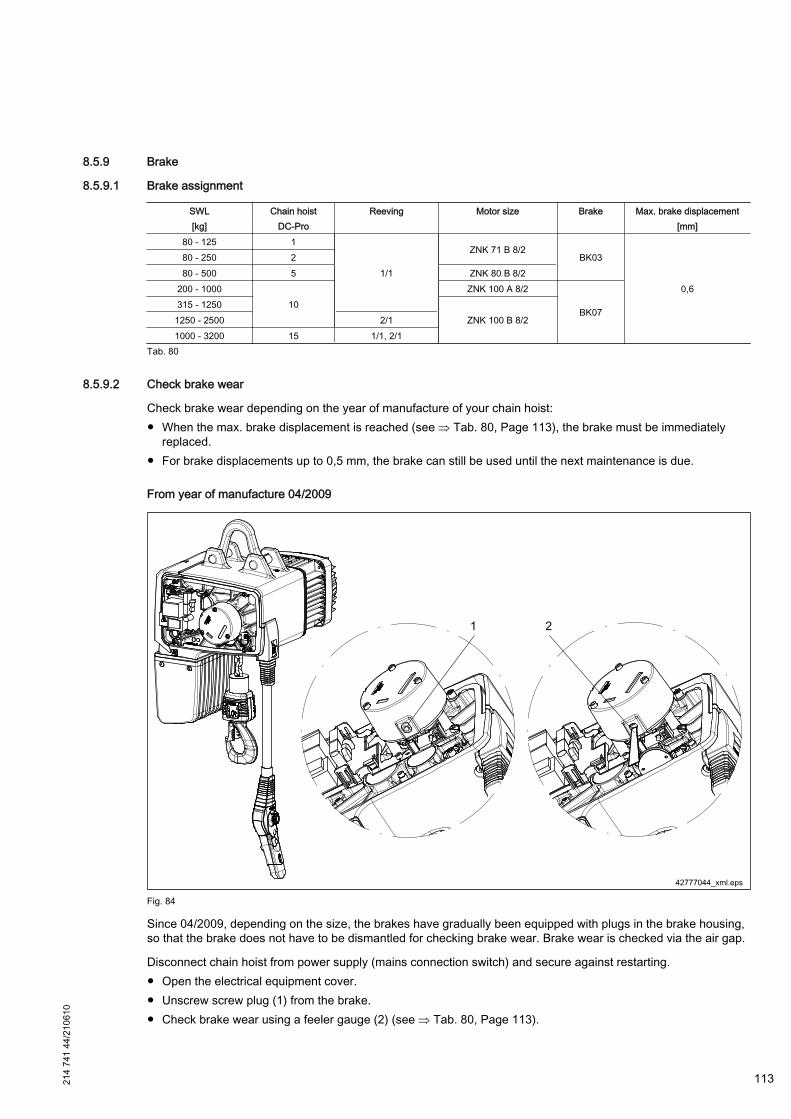
8.5.9 Brake
8.5.9.1 Brake assignment
SWL Chain hoist Reeving Motor size Brake Max. brake displacement[kg] DC-Pro [mm]
80 - 125 1
1/1
ZNK 71 B 8/2BK03
0,6
80 - 250 280 - 500 5 ZNK 80 B 8/2
200 - 100010
ZNK 100 A 8/2
BK07315 - 1250
ZNK 100 B 8/21250 - 2500 2/11000 - 3200 15 1/1, 2/1
Tab. 80
8.5.9.2 Check brake wear
Check brake wear depending on the year of manufacture of your chain hoist:● When the max. brake displacement is reached (see ⇒ Tab. 80, Page 113), the brake must be immediately
replaced.● For brake displacements up to 0,5 mm, the brake can still be used until the next maintenance is due.
From year of manufacture 04/2009
Fig. 84
Since 04/2009, depending on the size, the brakes have gradually been equipped with plugs in the brake housing,so that the brake does not have to be dismantled for checking brake wear. Brake wear is checked via the air gap.
Disconnect chain hoist from power supply (mains connection switch) and secure against restarting.● Open the electrical equipment cover.● Unscrew screw plug (1) from the brake.● Check brake wear using a feeler gauge (2) (see ⇒ Tab. 80, Page 113).
214
741
44/2
1061
0
113
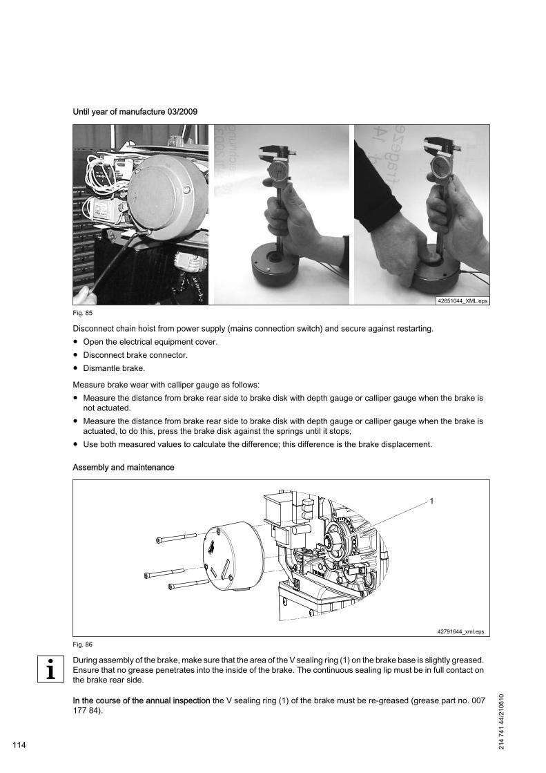
Until year of manufacture 03/2009
Fig. 85
Disconnect chain hoist from power supply (mains connection switch) and secure against restarting.● Open the electrical equipment cover.● Disconnect brake connector.● Dismantle brake.
Measure brake wear with calliper gauge as follows:● Measure the distance from brake rear side to brake disk with depth gauge or calliper gauge when the brake is
not actuated.● Measure the distance from brake rear side to brake disk with depth gauge or calliper gauge when the brake is
actuated, to do this, press the brake disk against the springs until it stops;● Use both measured values to calculate the difference; this difference is the brake displacement.
Assembly and maintenance
Fig. 86
During assembly of the brake, make sure that the area of the V sealing ring (1) on the brake base is slightly greased.Ensure that no grease penetrates into the inside of the brake. The continuous sealing lip must be in full contact onthe brake rear side.
In the course of the annual inspection the V sealing ring (1) of the brake must be re-greased (grease part no. 007177 84).
114 214
741
44/2
1061
0
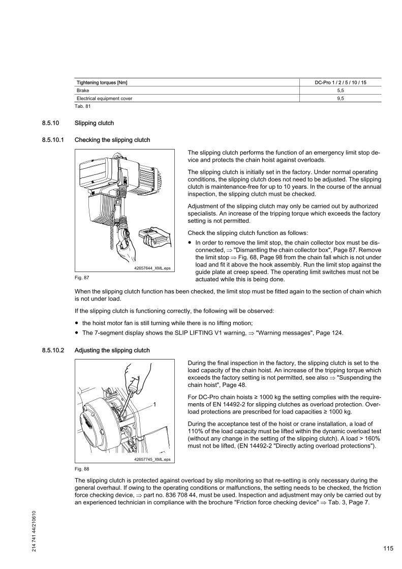
Tightening torques [Nm] DC-Pro 1 / 2 / 5 / 10 / 15Brake 5,5Electrical equipment cover 9,5
Tab. 81
8.5.10 Slipping clutch
8.5.10.1 Checking the slipping clutch
Fig. 87
The slipping clutch performs the function of an emergency limit stop de‐vice and protects the chain hoist against overloads.
The slipping clutch is initially set in the factory. Under normal operatingconditions, the slipping clutch does not need to be adjusted. The slippingclutch is maintenance-free for up to 10 years. In the course of the annualinspection, the slipping clutch must be checked.
Adjustment of the slipping clutch may only be carried out by authorizedspecialists. An increase of the tripping torque which exceeds the factorysetting is not permitted.
Check the slipping clutch function as follows:● In order to remove the limit stop, the chain collector box must be dis‐
connected, ⇒ "Dismantling the chain collector box", Page 87. Removethe limit stop ⇒ Fig. 68, Page 98 from the chain fall which is not underload and fit it above the hook assembly. Run the limit stop against theguide plate at creep speed. The operating limit switches must not beactuated while this is being done.
When the slipping clutch function has been checked, the limit stop must be fitted again to the section of chain whichis not under load.
If the slipping clutch is functioning correctly, the following will be observed:
● the hoist motor fan is still turning while there is no lifting motion;● The 7-segment display shows the SLIP LIFTING V1 warning, ⇒ "Warning messages", Page 124.
8.5.10.2 Adjusting the slipping clutch
Fig. 88
During the final inspection in the factory, the slipping clutch is set to theload capacity of the chain hoist. An increase of the tripping torque whichexceeds the factory setting is not permitted, see also ⇒ "Suspending thechain hoist", Page 48.
For DC-Pro chain hoists ≥ 1000 kg the setting complies with the require‐ments of EN 14492-2 for slipping clutches as overload protection. Over‐load protections are prescribed for load capacities ≥ 1000 kg.
During the acceptance test of the hoist or crane installation, a load of110% of the load capacity must be lifted within the dynamic overload test(without any change in the setting of the slipping clutch). A load > 160%must not be lifted, (EN 14492-2 "Directly acting overload protections").
The slipping clutch is protected against overload by slip monitoring so that re-setting is only necessary during thegeneral overhaul. If owing to the operating conditions or malfunctions, the setting needs to be checked, the frictionforce checking device, ⇒ part no. 836 708 44, must be used. Inspection and adjustment may only be carried out byan experienced technician in compliance with the brochure "Friction force checking device" ⇒ Tab. 3, Page 7.
214
741
44/2
1061
0
115
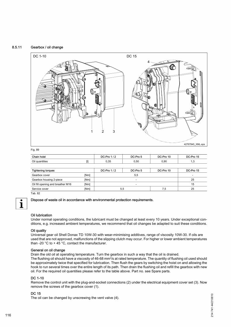
8.5.11 Gearbox / oil change
Fig. 89
Chain hoist DC-Pro 1 / 2 DC-Pro 5 DC-Pro 10 DC-Pro 15Oil quantities [l] 0,35 0,50 0,90 1,3 Tightening torques DC-Pro 1 / 2 DC-Pro 5 DC-Pro 10 DC-Pro 15Gearbox cover [Nm] 5,5 -Gearbox housing 2-piece [Nm] - 25Oil fill opening and breather M16 [Nm] - 15Service cover [Nm] 5,5 7,5 25
Tab. 82
Dispose of waste oil in accordance with environmental protection requirements.
Oil lubricationUnder normal operating conditions, the lubricant must be changed at least every 10 years. Under exceptional con‐ditions, e.g. increased ambient temperatures, we recommend that oil changes be adapted to suit these conditions.
Oil qualityUniversal gear oil Shell Donax TD 10W-30 with wear-minimising additives, range of viscosity 10W-30. If oils areused that are not approved, malfunctions of the slipping clutch may occur. For higher or lower ambient temperaturesthan -20 °C to + 45 °C, contact the manufacturer.
General on oil changeDrain the old oil at operating temperature. Turn the gearbox in such a way that the oil is drained.The flushing oil should have a viscosity of 46-68 mm2/s at rated temperature. The quantity of flushing oil used shouldbe approximately twice that specified for lubrication. Then flush the gears by switching the hoist on and allowing thehook to run several times over the entire length of its path. Then drain the flushing oil and refill the gearbox with newoil. For the required oil quantities please refer to the table above. Part no. see Spare parts.
DC 1-10Remove the control unit with the plug-and-socket connections (2) under the electrical equipment cover set (3). Nowremove the screws of the gearbox cover (1).
DC 15The oil can be changed by unscrewing the vent valve (4).
116 214
741
44/2
1061
0
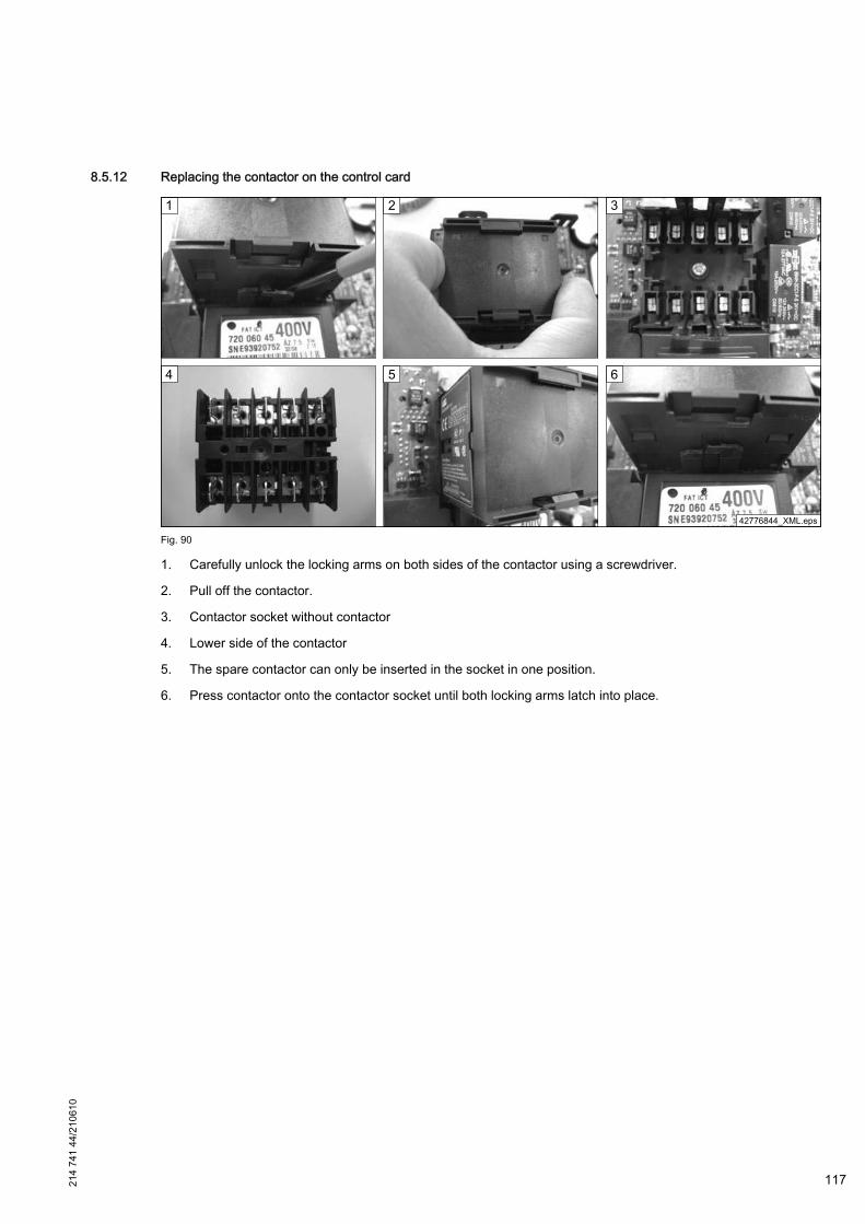
8.5.12 Replacing the contactor on the control card
Fig. 90
1. Carefully unlock the locking arms on both sides of the contactor using a screwdriver.
2. Pull off the contactor.
3. Contactor socket without contactor
4. Lower side of the contactor
5. The spare contactor can only be inserted in the socket in one position.
6. Press contactor onto the contactor socket until both locking arms latch into place.
214
741
44/2
1061
0
117
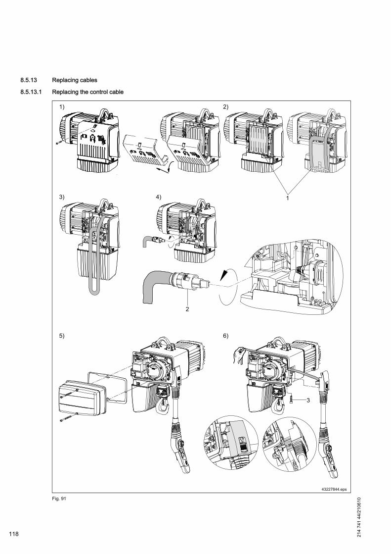
8.5.13 Replacing cables
8.5.13.1 Replacing the control cable
Fig. 91
118 214
741
44/2
1061
0

DANGER
Live componentsDanger to life and limb.Work on the electrical equipment may only be carried out by a qualified electrician or by trained personnel.
1. Disconnect chain hoist from power supply (mains connection switch) and secure against restarting.Open and disengage the service cover.
2. Remove and open the bag (1) with the control cable.
3. Take the control cable out of the pocket.
4. Loosen bayonet lock (2) by turning and remove control cable plug connection.
5. Unscrew electrical equipment cover.
6. Loosen the screw (3) on the control cable lock and remove the lock. Remove the control cable.
Fit the new control cable in reverse order.
It must be ensured that● the groove of the connector holder matches the swivel lock in the enclosure and● that the two pins on the enclosure match the bayonet lock.
Fitting the control pendant ⇒ "Connecting the control pendant", Page 46.
Height adjustment of the control pendant ⇒ "Height adjustment of the control pendant", Page 51.
Tightening torques [Nm] DC-Pro 1 DC-Pro 2 DC-Pro 5 DC-Pro 10 DC-Pro 15Electrical equipment cover 9,5Service cover 5,5 7,5 25Control cable lock 11,0
Tab. 83
214
741
44/2
1061
0
119
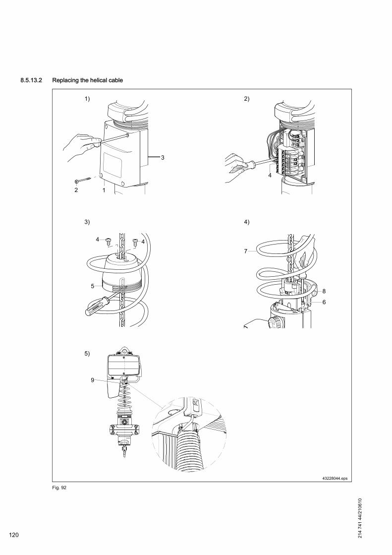
8.5.13.2 Replacing the helical cable
Fig. 92
120 214
741
44/2
1061
0
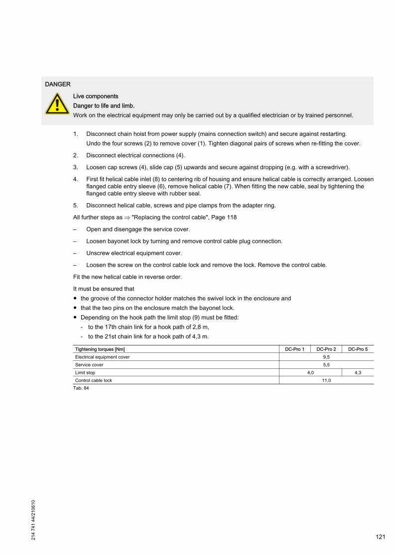
DANGER
Live componentsDanger to life and limb.Work on the electrical equipment may only be carried out by a qualified electrician or by trained personnel.
1. Disconnect chain hoist from power supply (mains connection switch) and secure against restarting.Undo the four screws (2) to remove cover (1). Tighten diagonal pairs of screws when re-fitting the cover.
2. Disconnect electrical connections (4).
3. Loosen cap screws (4), slide cap (5) upwards and secure against dropping (e.g. with a screwdriver).
4. First fit helical cable inlet (8) to centering rib of housing and ensure helical cable is correctly arranged. Loosenflanged cable entry sleeve (6), remove helical cable (7). When fitting the new cable, seal by tightening theflanged cable entry sleeve with rubber seal.
5. Disconnect helical cable, screws and pipe clamps from the adapter ring.
All further steps as ⇒ "Replacing the control cable", Page 118
– Open and disengage the service cover.
– Loosen bayonet lock by turning and remove control cable plug connection.
– Unscrew electrical equipment cover.
– Loosen the screw on the control cable lock and remove the lock. Remove the control cable.
Fit the new helical cable in reverse order.
It must be ensured that● the groove of the connector holder matches the swivel lock in the enclosure and● that the two pins on the enclosure match the bayonet lock.● Depending on the hook path the limit stop (9) must be fitted:
- to the 17th chain link for a hook path of 2,8 m,- to the 21st chain link for a hook path of 4,3 m.
Tightening torques [Nm] DC-Pro 1 DC-Pro 2 DC-Pro 5Electrical equipment cover 9,5Service cover 5,5Limit stop 4,0 4,3Control cable lock 11,0
Tab. 84
214
741
44/2
1061
0
121
9 Faults / Warnings
9.1 Safety instructions for faults / warnings
WARNING
Inappropriate fault eliminationDanger to life and limb. Danger of machine damage.Faults may only be eliminated by qualified instructed personnel(⇒ "Definition of personnel", Page 10 ) in compli‐ance with the safety instructions.
DANGER
Live componentsDanger to life and limb.Work on electrical equipment may only be carried out by qualified specialist personnel(⇒ "Definition of personnel",Page 10 ) in compliance with the safety instructions.Before starting work, the electrical supply must be switched off. The mains connection or isolator switch must besecured against unauthorized or accidental reconnection by means of a padlock.
WARNING
Risk of burningThere is a risk of burning when touching the chain hoist after operation.Do not touch the hot motor housing. Let motor cool down, before eliminating the fault.
What to do in case of faults
1. In the case of faults which constitute an immediate danger for persons and property and/or operating safety,the machine must immediately be shut down by means of the emergency stop device.
2. Switch off the chain hoist on the mains connection switch or isolator switch and secure it against restarting.
3. Inform the responsible person on site about the fault.
4. Have the fault and the cause of the fault determined and eleminated by authorized specialist personnel.
What to do after the fault has been eliminated
WARNING
Check appropriate assembly.Before restarting make sure that– the fault and the cause of the fault have been eliminated.– all safety devices have been fitted properly and are in perfect working order.– no persons are in the danger zone of the unit.
122 214
741
44/2
1061
0
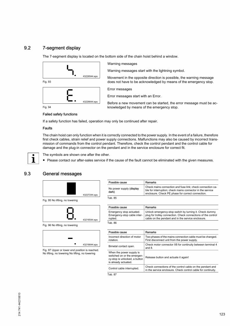
9.2 7-segment displayThe 7-segment display is located on the bottom side of the chain hoist behind a window.
Fig. 93
Warning messages
Warning messages start with the lightning symbol.
Movement in the opposite direction is possible, the warning messagedoes not have to be acknowledged by means of the emergency stop.
Fig. 94
Error messages
Error messages start with an Error.
Before a new movement can be started, the error message must be ac‐knowledged by means of the emergency stop.
Failed safety functions
If a safety function has failed, operation may only be continued after repair.
Faults
The chain hoist can only function when it is correctly connected to the power supply. In the event of a failure, thereforefirst check cables, strain relief and power supply connections. Malfunctions may also be caused by incorrect trans‐mission of commands from the control pendant. Therefore, check the control pendant and the control cable fordamage and the plug-in connector on the pendant and in the service enclosure for correct fit.
The symbols are shown one after the other.● Please contact our after-sales service if the cause of the fault cannot be eliminated with the given measures.
9.3 General messages
Fig. 95 No lifting, no lowering
Possible cause Remarks
No power supply (displaydark)
Check mains connection and fuse link; check connection ca‐ble for interruption; check mains connector in the serviceenclosure. Check PE phase for correct connection.
Tab. 85
Fig. 96 No lifting, no lowering
Possible cause RemarksEmergency stop actuated.Emergency-stop cable inter‐rupted.
Unlock emergency-stop switch by turning it. Check dummyplug for trolley connection. Check connections of the controlcable on the pendant and in the service enclosure.
Tab. 86
Fig. 97 Upper or lower end position is reached.No lifting, no lowering No lifting, no lowering
Possible cause RemarksIncorrect direction of motorrotation.
Two phases of the mains connection cable must be changed.First disconnect unit from the power supply.
Bimetal contact open. Check motor connector X8 for continuity between terminal 4and 8.
When the power supply isswitched on or the emergen‐cy-stop is unlocked, a buttonis already actuated.
Release button and actuate it again!
Control cable interrupted. Check connections of the control cable on the pendant andin the service enclosure. Check control cable for continuity.
Tab. 87
214
741
44/2
1061
0
123
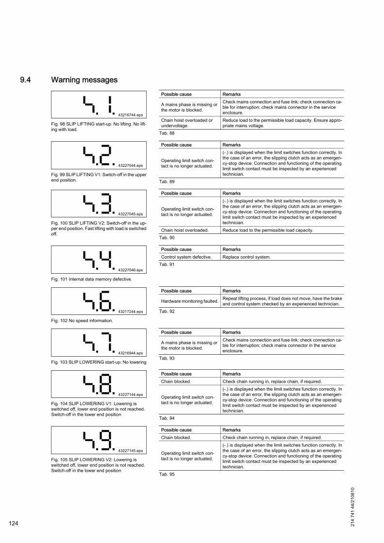
9.4 Warning messages
Fig. 98 SLIP LIFTING start-up: No lifting. No lift‐ing with load.
Possible cause Remarks
A mains phase is missing orthe motor is blocked.
Check mains connection and fuse link; check connection ca‐ble for interruption; check mains connector in the serviceenclosure.
Chain hoist overloaded orundervoltage.
Reduce load to the permissible load capacity. Ensure appro‐priate mains voltage.
Tab. 88
Fig. 99 SLIP LIFTING V1: Switch-off in the upperend position.
Possible cause Remarks
Operating limit switch con‐tact is no longer actuated.
(-.) is displayed when the limit switches function correctly. Inthe case of an error, the slipping clutch acts as an emergen‐cy-stop device: Connection and functioning of the operatinglimit switch contact must be inspected by an experiencedtechnician.
Tab. 89
Fig. 100 SLIP LIFTING V2: Switch-off in the up‐per end position. Fast lifting with load is switchedoff.
Possible cause Remarks
Operating limit switch con‐tact is no longer actuated.
(-.) is displayed when the limit switches function correctly. Inthe case of an error, the slipping clutch acts as an emergen‐cy-stop device: Connection and functioning of the operatinglimit switch contact must be inspected by an experiencedtechnician.
Chain hoist overloaded. Reduce load to the permissible load capacity.Tab. 90
Fig. 101 Internal data memory defective.
Possible cause RemarksControl system defective. Replace control system.
Tab. 91
Fig. 102 No speed information.
Possible cause Remarks
Hardware monitoring faulted. Repeat lifting process, if load does not move, have the brakeand control system checked by an experienced technician.
Tab. 92
Fig. 103 SLIP LOWERING start-up: No lowering
Possible cause Remarks
A mains phase is missing orthe motor is blocked.
Check mains connection and fuse link; check connection ca‐ble for interruption; check mains connector in the serviceenclosure.
Tab. 93
Fig. 104 SLIP LOWERING V1: Lowering isswitched off, lower end position is not reached.Switch-off in the lower end position
Possible cause RemarksChain blocked. Check chain running in, replace chain, if required.
Operating limit switch con‐tact is no longer actuated.
(-.) is displayed when the limit switches function correctly. Inthe case of an error, the slipping clutch acts as an emergen‐cy-stop device: Connection and functioning of the operatinglimit switch contact must be inspected by an experiencedtechnician.
Tab. 94
Fig. 105 SLIP LOWERING V2: Lowering isswitched off, lower end position is not reached.Switch-off in the lower end position
Possible cause RemarksChain blocked. Check chain running in, replace chain, if required.
Operating limit switch con‐tact is no longer actuated.
(-.) is displayed when the limit switches function correctly. Inthe case of an error, the slipping clutch acts as an emergen‐cy-stop device: Connection and functioning of the operatinglimit switch contact must be inspected by an experiencedtechnician.
Tab. 95
124 214
741
44/2
1061
0

9.5 Error messages
Fig. 106 Hoist unit: Speed error or drive is ob‐structed. Chain hoist is blocked.
Possible cause Remarks
Drive blocked.Check error message by actuating and unlocking the emer‐gency stop. Then actuate Lowering. If necessary, removesuspended load.
Speed measurement failed. Replace hoist control system.Tab. 96
Fig. 107 Hoist unit: Overspeed or load cannot beheld. Lowering with load is switched off.
Possible cause Remarks
Lowering speed too high.Reduce load to the permissible load capacity. Check mainsconnection and fuse link; check connection cable for inter‐ruption; check mains connector in the service enclosure.
Tab. 97
Fig. 108 Hoist unit: Monitoring electronics defec‐tive. Chain hoist is blocked.
Possible cause Remarks
Hardware error of controlsystem.
Check error message by actuating and unlocking the emer‐gency stop. Then actuate Lowering. If necessary, removesuspended load.
Monitoring electronics defec‐tive. Replace hoist control system.
Tab. 98
Fig. 109 Hoist unit: Monitoring electronics defec‐tive. Chain hoist is blocked.
Possible cause Remarks
Hardware error of controlsystem.
Check error message by actuating and unlocking the emer‐gency stop. Then actuate Lowering. If necessary, removesuspended load.
Monitoring electronics defec‐tive. Replace hoist control system.
Tab. 99
Fig. 110 Hoist unit: Motor runs in wrong direction.Chain hoist is blocked.
Possible cause Remarks
Direction cannot be switch‐ed.
Check error message by actuating and unlocking the emer‐gency stop. Then actuate Lowering. If necessary, removesuspended load.Replace hoist control system.
Tab. 100
214
741
44/2
1061
0
125
10 Disassembly / Disposal
10.1 General
WARNING
Before disassembly, follow the safety instructions in ⇒ "Maintenance / repair", Page 78 of these operating in‐structions.
For information on removing track sections, trolleys and current collector trolleys refer to chapter ⇒ "Assembly",Page 43 of these operating instructions. Other parts are removed in reverse order to assembly.
Unless a return or disposal agreement has been concluded, separated components must be recycled after properremoval:● Scrap any remaining metallic material,● Dispose of plastic elements for recycling,● Separate and dispose of any other components by material type.
Electric scrap, electronic components, lubricants and other auxiliary materials are subject to special disposal reg‐ulations and may only be disposed of by certified companies.
National disposal regulations must be considered regarding environmentally friendly disposal. Further informationcan be obtained from corresponding local authorities.
126 214
741
44/2
1061
0
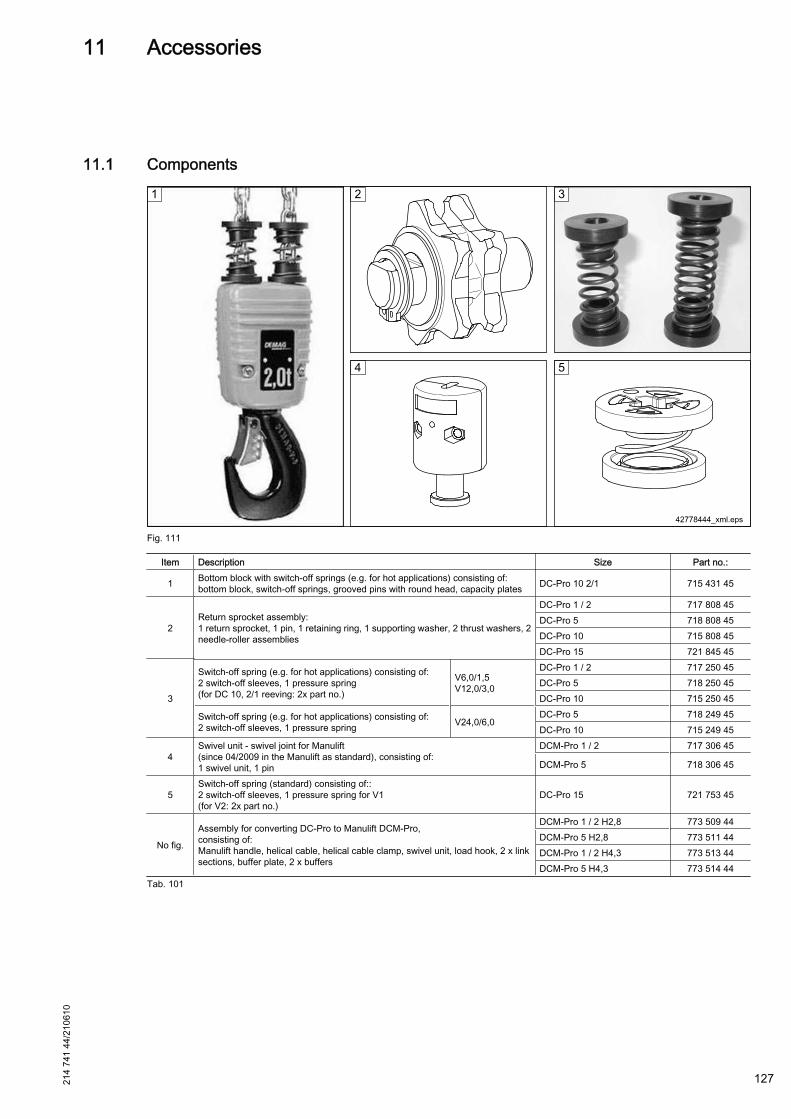
11 Accessories
11.1 Components
Fig. 111
Item Description Size Part no.:
1 Bottom block with switch-off springs (e.g. for hot applications) consisting of:bottom block, switch-off springs, grooved pins with round head, capacity plates DC-Pro 10 2/1 715 431 45
2Return sprocket assembly:1 return sprocket, 1 pin, 1 retaining ring, 1 supporting washer, 2 thrust washers, 2needle-roller assemblies
DC-Pro 1 / 2 717 808 45DC-Pro 5 718 808 45DC-Pro 10 715 808 45DC-Pro 15 721 845 45
3
Switch-off spring (e.g. for hot applications) consisting of:2 switch-off sleeves, 1 pressure spring(for DC 10, 2/1 reeving: 2x part no.)
V6,0/1,5V12,0/3,0
DC-Pro 1 / 2 717 250 45DC-Pro 5 718 250 45DC-Pro 10 715 250 45
Switch-off spring (e.g. for hot applications) consisting of:2 switch-off sleeves, 1 pressure spring V24,0/6,0
DC-Pro 5 718 249 45DC-Pro 10 715 249 45
4Swivel unit - swivel joint for Manulift(since 04/2009 in the Manulift as standard), consisting of:1 swivel unit, 1 pin
DCM-Pro 1 / 2 717 306 45
DCM-Pro 5 718 306 45
5Switch-off spring (standard) consisting of::2 switch-off sleeves, 1 pressure spring for V1(for V2: 2x part no.)
DC-Pro 15 721 753 45
No fig.
Assembly for converting DC-Pro to Manulift DCM-Pro,consisting of:Manulift handle, helical cable, helical cable clamp, swivel unit, load hook, 2 x linksections, buffer plate, 2 x buffers
DCM-Pro 1 / 2 H2,8 773 509 44DCM-Pro 5 H2,8 773 511 44DCM-Pro 1 / 2 H4,3 773 513 44DCM-Pro 5 H4,3 773 514 44
Tab. 101
214
741
44/2
1061
0
127

2147
40E
T.in
dd/2
1061
0
128
12 Spare parts
12.1 Overview
1/1 reeving 2/1 reeving
42764249.eps
Spare parts for DC 15 are being prepared. Please contact our customer service department.
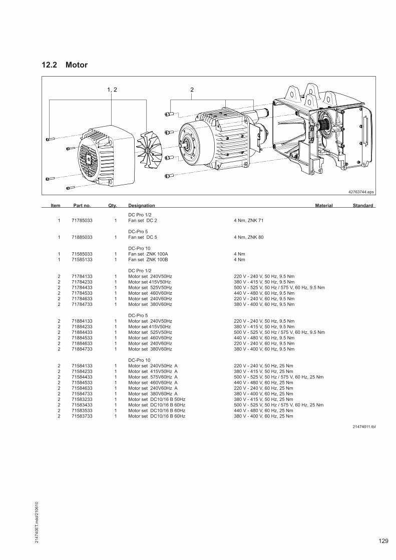
2147
40E
T.in
dd/2
1061
0
129
12.2 Motor
42763744.eps
Item Part no. Qty. Designation Material Standard
DC Pro 1/2 1 71785033 1 Fan set DC 2 4 Nm, ZNK 71 DC-Pro 5 1 71885033 1 Fan set DC 5 4 Nm, ZNK 80 DC-Pro 10 1 71585033 1 Fan set ZNK 100A 4 Nm 1 71585133 1 Fan set ZNK 100B 4 Nm DC Pro 1/2 2 71784133 1 Motor set 240V50Hz 220 V - 240 V, 50 Hz, 9.5 Nm 2 71784233 1 Motor set 415V50Hz 380 V - 415 V, 50 Hz, 9.5 Nm 2 71784433 1 Motor set 525V50Hz 500 V - 525 V, 50 Hz / 575 V, 60 Hz, 9.5 Nm 2 71784533 1 Motor set 460V60Hz 440 V - 480 V, 60 Hz, 9.5 Nm 2 71784633 1 Motor set 240V60Hz 220 V - 240 V, 60 Hz, 9.5 Nm 2 71784733 1 Motor set 380V60Hz 380 V - 400 V, 60 Hz, 9.5 Nm DC-Pro 5 2 71884133 1 Motor set 240V50Hz 220 V - 240 V, 50 Hz, 9.5 Nm 2 71884233 1 Motor set 415V50Hz 380 V - 415 V, 50 Hz, 9.5 Nm 2 71884433 1 Motor set 525V50Hz 500 V - 525 V, 50 Hz / 575 V, 60 Hz, 9.5 Nm 2 71884533 1 Motor set 460V60Hz 440 V - 480 V, 60 Hz, 9.5 Nm 2 71884633 1 Motor set 240V60Hz 220 V - 240 V, 60 Hz, 9.5 Nm 2 71884733 1 Motor set 380V60Hz 380 V - 400 V, 60 Hz, 9.5 Nm DC-Pro 10 2 71584133 1 Motor set 240V50Hz A 220 V - 240 V, 50 Hz, 25 Nm 2 71584233 1 Motor set 415V50Hz A 380 V - 415 V, 50 Hz, 25 Nm 2 71584433 1 Motor set 575V60Hz A 500 V - 525 V, 50 Hz / 575 V, 60 Hz, 25 Nm 2 71584533 1 Motor set 460V60Hz A 440 V - 480 V, 60 Hz, 25 Nm 2 71584633 1 Motor set 240V60Hz A 220 V - 240 V, 60 Hz, 25 Nm 2 71584733 1 Motor set 380V60Hz A 380 V - 400 V, 60 Hz, 25 Nm 2 71583233 1 Motor set DC10/16 B 50Hz 380 V - 415 V, 50 Hz, 25 Nm 2 71583433 1 Motor set DC10/16 B 60Hz 500 V - 525 V, 50 Hz / 575 V, 60 Hz, 25 Nm 2 71583533 1 Motor set DC10/16 B 60Hz 440 V - 480 V, 60 Hz, 25 Nm 2 71583733 1 Motor set DC10/16 B 60Hz 380 V - 400 V, 60 Hz, 25 Nm
21474011.tbl
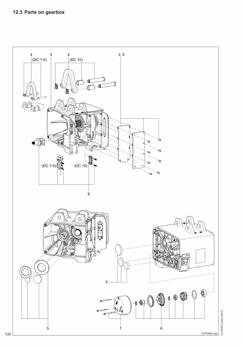
2147
40E
T.in
dd/2
1061
0
130
12.3 Parts on gearbox
42763845.eps
2147
40E
T.in
dd/2
1061
0
131
Item Part no. Qty. Designation Material Standard
3 71771533 1 Gearbox set DC-PRO 1 V8/2 DC-Pro 1; V8/2 3 71790533 1 Gearbox set DC-PRO 2 V8/2 DC-Pro 2; V8/2 3 71790633 1 Gearbox set DC-PRO 2 V16/4 DC-Pro 2; V16/4 3 71890833 1 Gearbox set DC-PRO 5 V8/2 DC-Pro 5; V8/2 3 71890933 1 Gearbox set DC-PRO 5 V16/4 DC-Pro 5; V16/4 3 71800933 1 Gearbox set DC5 V3 DC-Pro 5; V24/6 3 71590533 1 Gearbox set DC-PRO10V6/1,5 DC-Pro 10, 1/1 reeving; V6/1,5 3 71590833 1 Gearbox set DC-PRO 10 V8/2 DC-Pro 10,1/1 reeving; V8/2 3 71590633 1 Gearbox set DC-PRO10 V12/3 DC-Pro 10, 1/1 reeving; V12/3 3 71500933 1 Gearbox DC-Pro10 V24 DC-Pro 10, 1/1 reeving; V24/6 3 71590933 1 Gearbox set DC-PRO 10 V4/1 DC-Pro 10,2/1 reeving; V4/1 3 71590733 1 Gearbox set DC-PRO10V6/1,5 DC-Pro 10, 2/1 reeving; V6/1,5 Year of manufacture 2004 until 03/2007 3 71890533 1 Gearbox set DC-PRO5 V6/1,5 DC-Pro 5; V6/1,5 3 71890633 1 Gearbox set DC-PRO 5 V12/3 DC-Pro 5; V12/3 4 71897433 1 Suspension set DC 1- 5 4 71597433 1 Suspension set DC10 5 71791933 1 Gear oil/seal Pro 2 5,5 Nm, 0,35 litres, DC-Pro 1 / 2 5 71891933 1 Gear oil/seal Pro 5 5,5 Nm, 0.5 litres 5 71591933 1 Gear oil/seal DC10 5,5 Nm, 0,9 litres 6 71894733 1 Adjusting nut/pulse wheel DC1/2/5 6 71594733 1 Adjusting nut/pulse wheel DC10 DC Pro 1/2/5 7 71887133 1 Brake set 180V 380 V - 415 V, 50 Hz, 5,5 Nm 7 71887233 1 Brake set 216V 440 V - 480 V, 60 Hz, 5,5 Nm 7 71887333 1 Brake set DCS 1-5 104V 220 V - 240 V, 50/60 Hz, 5,5 Nm 7 71887433 1 Brake set 258V 500 V - 525 V, 50 Hz / 575 V, 60 Hz, 5,5 Nm DC-Pro 10 7 71587133 1 Brake set DC10 180V 380 V - 415 V, 50 Hz, 5,5 Nm 7 71587233 1 Brake set DC 10 216V 440 V - 480 V, 60 Hz, 5,5 Nm 7 71587333 1 Brake set DC/DCS10 220 V - 240 V, 50/60 Hz, 5,5 Nm 7 71587433 1 Brake set DC10 258V 500 V - 525 V, 50 Hz / 575 V, 60 Hz, 5,5 Nm 8 71885633 1 Insert/plug
21474012.tbl
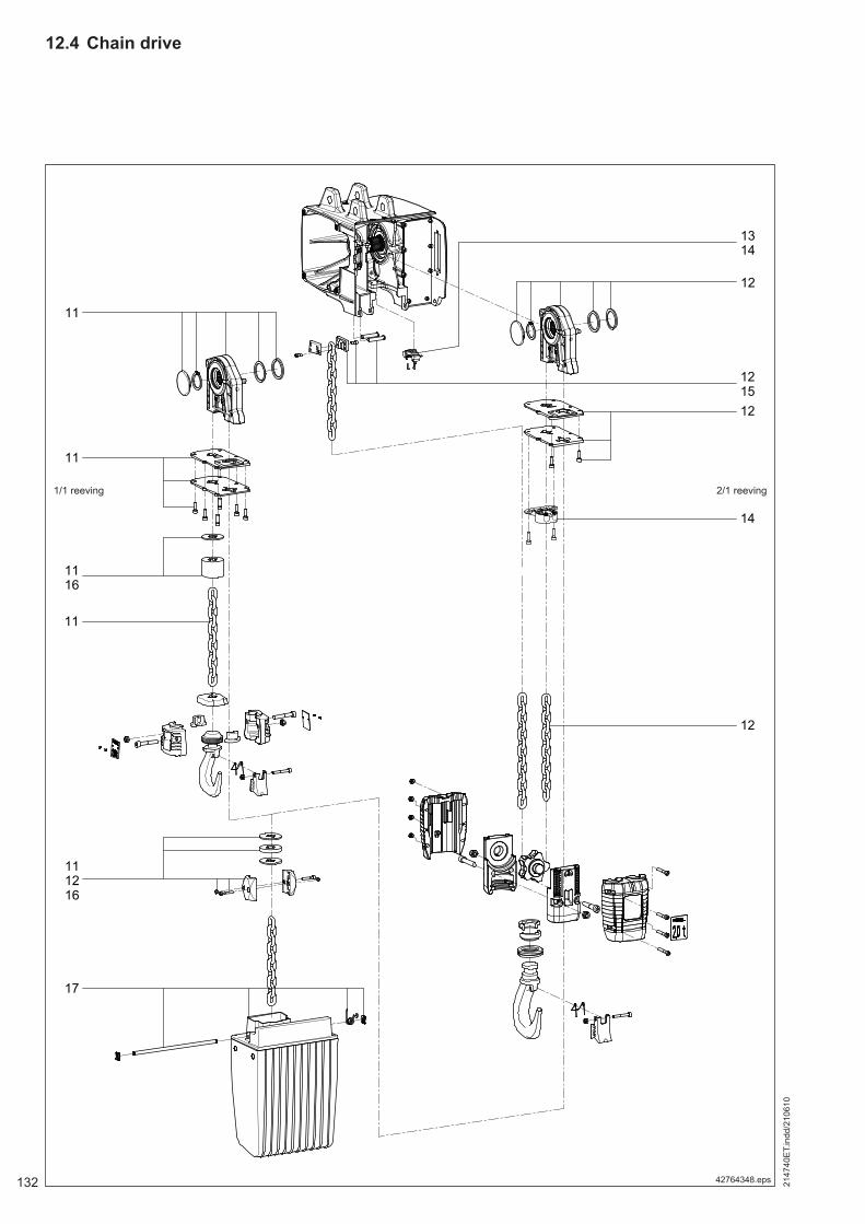
2147
40E
T.in
dd/2
1061
0
132
12.4 Chain drive
42764348.eps
1/1 reeving 2/1 reeving
2147
40E
T.in
dd/2
1061
0
1331) See section 8.5.5.7
Item Part no. Qty. Designation Material Standard
11 71795033 1 Chain set DC/DCM 1/2 H 5 4.0 Nm 11 71795133 1 Chain set DC 1/2 H 8 4.0 Nm 11 71895033 1 Chain set DC/DCM 5 H 5 4.3 Nm 11 71895133 1 Chain set DC 5 H 8 4.3 Nm 11 71595033 1 Chain set DC10 1/1 H 5 7.4 Nm 11 71595133 1 Chain set DC10 1/1 H 8 7.4 Nm 11 75263733 1 Chain set DC 10 5m 1/1 7,4 Nm, for GGS 1) 11 75263833 1 Chain set DC 10 8m 1/1 7,4 Nm, for GGS 1) 12 71596033 1 Chain set DC10 2/1 H 5 DC 10 2/1, 7,4 Nm 12 71596133 1 Chain set DC10 2/1 H 8 DC 10 2/1, 7,4 Nm 12 75263933 1 Chain set DC 10 5m 2/1 DC 10 2/1, 7,4 Nm, for GGS 1) 12 75264033 1 Chain set DC 10 8m 2/1 DC 10 2/1, 7,4 Nm, for GGS 1) 13 71888033 1 Limit switch set DC 1 2/5, 3 Nm 14 71588033 1 Limit switch set DC 10, 3 Nm 15 71527933 1 Chain anchorage 2/1 set DC 10 2/1 16 71795333 1 Buffer set DC 1/2 16 71895333 1 Buffer set DC5 16 71595333 1 Buffer set DC10 17 71798633 1 Chain collector set DC1/2 5m 17 71798733 1 Chain collector set DC1/2 8m 17 71898633 1 Chain collector set DC5 5m 17 71898733 1 Chain collector set DC5 8m 17 71598633 1 Chain collector DC10 1/1 5m 17 71598733 1 Chain collector DC10 1/1 8m DC 10 2/1 H5 # 17 71535045 1 Chain collector fl exible 20 m DC 10 2/1 H8
21474015.tbl
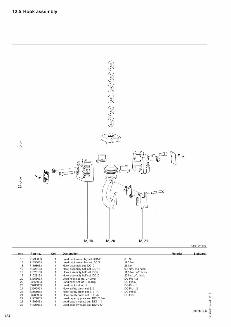
2147
40E
T.in
dd/2
1061
0
134
12.5 Hook assembly
42764044.eps
Item Part no. Qty. Designation Material Standard
18 71798033 1 Load hook assembly set DC1/2 6.8 Nm 18 71898033 1 Load hook assembly set DC 5 11.5 Nm 18 71598033 1 Hook assembly set DC10 25 Nm 19 71728133 1 Hook assembly half set DC1/2 6.8 Nm, w/o hook 19 71828133 1 Hook assembly half set DC5 11,5 Nm, w/o hook 19 71528133 1 Hook assembly half set DC10 25 Nm, w/o hook 20 83565033 1 Load hook set no. 2 400kg DC Pro 1/2 20 83665033 1 Load hook set no. 3 800kg DC-Pro 5 20 83765033 1 Load hook set no. 4 DC-Pro 10 21 83565933 1 Hook safety catch set S. 2 DC Pro 1/2 21 83665933 1 Hook safety catch set S. 3 x4 DC-Pro 5 21 83765933 1 Hook safety catch set S. 4 x5 DC-Pro 10 22 71724033 1 Load capacity plate set DC1/2 Pro 22 71393433 1 Load capacity plate set DK5 1/1 22 71528033 1 Load capacity plate set DC10 1/1
21474016.tbl
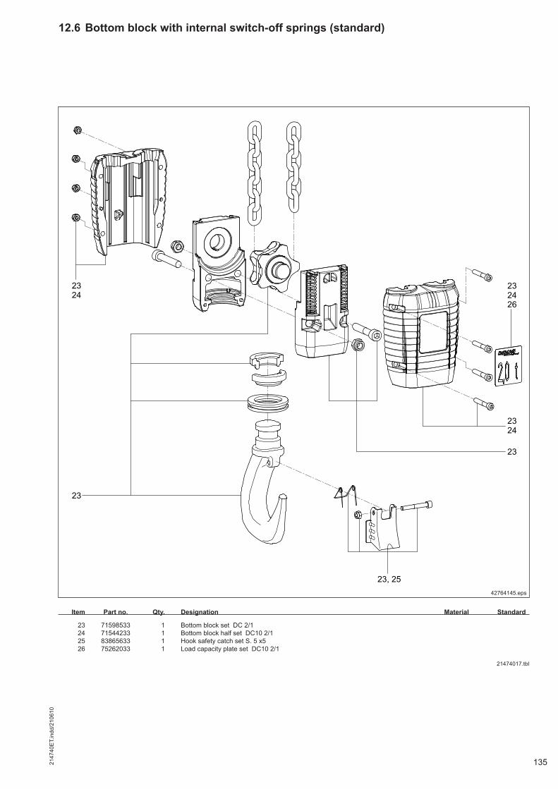
2147
40E
T.in
dd/2
1061
0
135
42764145.eps
12.6 Bottom block with internal switch-off springs (standard)
Item Part no. Qty. Designation Material Standard
23 71598533 1 Bottom block set DC 2/1 24 71544233 1 Bottom block half set DC10 2/1 25 83865633 1 Hook safety catch set S. 5 x5 26 75262033 1 Load capacity plate set DC10 2/1
21474017.tbl
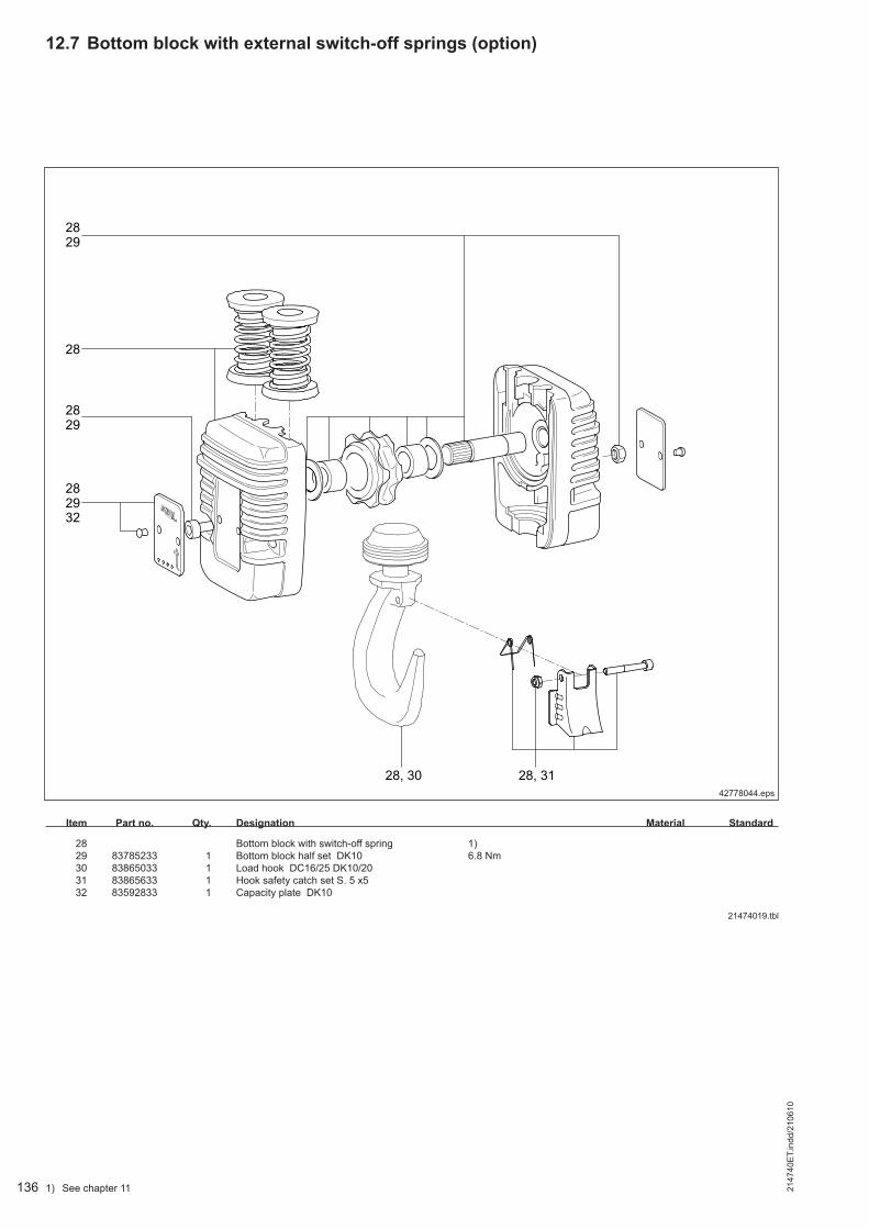
2147
40E
T.in
dd/2
1061
0
136
12.7 Bottom block with external switch-off springs (option)
42778044.eps
1) See chapter 11
Item Part no. Qty. Designation Material Standard
28 Bottom block with switch-off spring 1) 29 83785233 1 Bottom block half set DK10 6.8 Nm 30 83865033 1 Load hook DC16/25 DK10/20 31 83865633 1 Hook safety catch set S. 5 x5 32 83592833 1 Capacity plate DK10
21474019.tbl
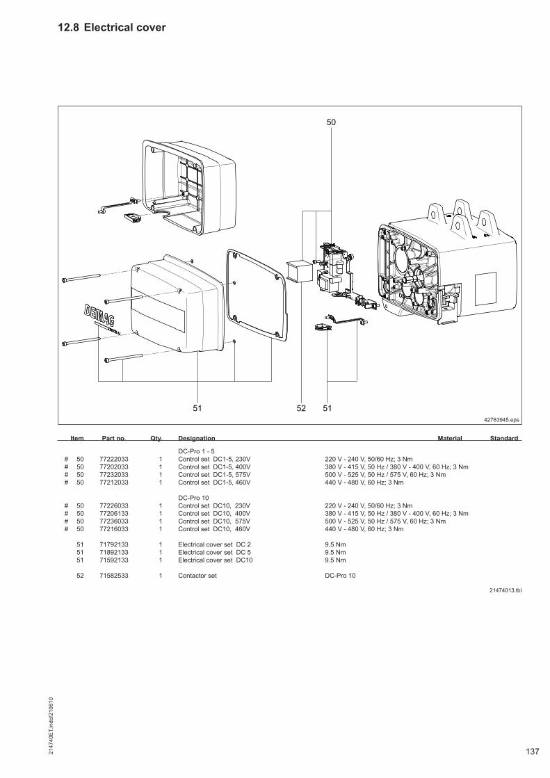
2147
40E
T.in
dd/2
1061
0
137
12.8 Electrical cover
42763945.eps
Item Part no. Qty. Designation Material Standard
DC-Pro 1 - 5 # 50 77222033 1 Control set DC1-5, 230V 220 V - 240 V, 50/60 Hz; 3 Nm # 50 77202033 1 Control set DC1-5, 400V 380 V - 415 V, 50 Hz / 380 V - 400 V, 60 Hz; 3 Nm # 50 77232033 1 Control set DC1-5, 575V 500 V - 525 V, 50 Hz / 575 V, 60 Hz; 3 Nm # 50 77212033 1 Control set DC1-5, 460V 440 V - 480 V, 60 Hz; 3 Nm DC-Pro 10 # 50 77226033 1 Control set DC10, 230V 220 V - 240 V, 50/60 Hz; 3 Nm # 50 77206133 1 Control set DC10, 400V 380 V - 415 V, 50 Hz / 380 V - 400 V, 60 Hz; 3 Nm # 50 77236033 1 Control set DC10, 575V 500 V - 525 V, 50 Hz / 575 V, 60 Hz; 3 Nm # 50 77216033 1 Control set DC10, 460V 440 V - 480 V, 60 Hz; 3 Nm 51 71792133 1 Electrical cover set DC 2 9.5 Nm 51 71892133 1 Electrical cover set DC 5 9.5 Nm 51 71592133 1 Electrical cover set DC10 9.5 Nm 52 71582533 1 Contactor set DC-Pro 10
21474013.tbl

2147
40E
T.in
dd/2
1061
0
138
12.9 Manulift
42509045.eps
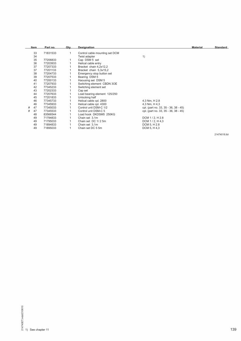
2147
40E
T.in
dd/2
1061
0
139
Item Part no. Qty. Designation Material Standard
33 71831533 1 Control cable mounting set DCM 34 Twist adapter 1) 35 77206833 1 Cap DSM 5 set 36 77203933 1 Helical cable entry 37 77207333 1 Bracket chain 4,2x12,2 37 77201133 1 Bracket chain 5,3x15,2 38 77204733 1 Emergency stop button set 39 77207533 1 Bearing DSM 5 40 77200133 1 Haousing set DSM 5 41 77207933 1 Switching element CBDN 3OE 42 77345233 1 Switching element set 43 77202333 1 Cap set 44 77207633 1 Load bearing element 125/250 45 77201833 1 Unlocking half 46 77345733 1 Helical cable cpl. 2800 4,3 Nm, H 2.8 46 77345933 1 Helical cable cpl. 4300 4,3 Nm, H 4,3 # 47 77345033 1 Control unit DSM-C 1/2 cpl. (part no. 33, 35 - 36, 38 - 45) # 47 77345533 1 Control unit DSM-C 5 cpl. (part no. 33, 35 - 36, 38 - 45) 48 83566544 1 Load hook DKDSM5 250KG 49 71794833 1 Chain set 3,1m DCM 1 / 2, H 2.8 49 71795033 1 Chain set DC 1/ 2 5m DCM 1 / 2, H 4,3 49 71894833 1 Chain set 3,1m DCM 5, H 2.8 49 71895033 1 Chain set DC 5 5m DCM 5, H 4,3
21474018.tbl
1) See chapter 11
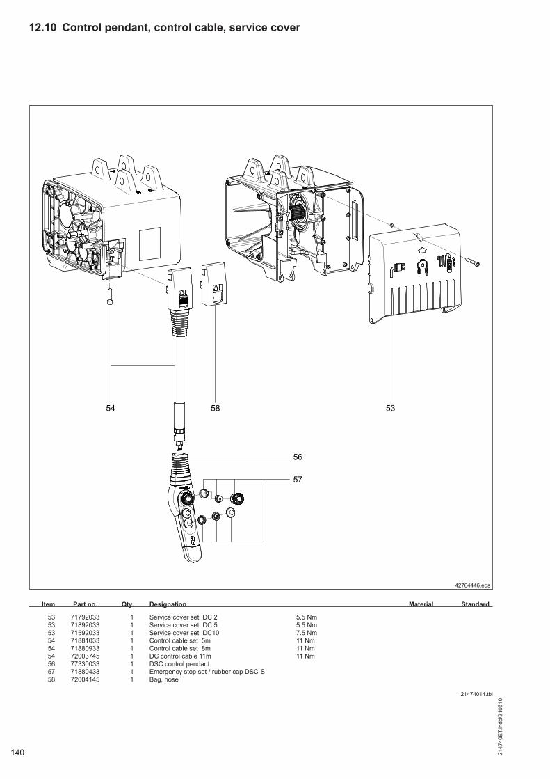
2147
40E
T.in
dd/2
1061
0
140
42764446.eps
12.10 Control pendant, control cable, service cover
Item Part no. Qty. Designation Material Standard
53 71792033 1 Service cover set DC 2 5.5 Nm 53 71892033 1 Service cover set DC 5 5.5 Nm 53 71592033 1 Service cover set DC10 7.5 Nm 54 71881033 1 Control cable set 5m 11 Nm 54 71880933 1 Control cable set 8m 11 Nm 54 72003745 1 DC control cable 11m 11 Nm 56 77330033 1 DSC control pendant 57 71880433 1 Emergency stop set / rubber cap DSC-S 58 72004145 1 Bag, hose
21474014.tbl
Index
A
Actual duration of service 81Actual load spectrum factor 81Actuator plate 67AC asynchronous motor 31
B
Bayonet lock 35, 46, 119Belt sling 37Bend protection sleeve 46Buffer 67Buffer plate 67, 110
C
Cable collector 52Canopy 30Chain link section 101Chain wear 92Closing eye 37Contactor control 32Continuity of the PE conductor connection 44Control cable stop 51Counterweight compensation 49Coupling pin 37Curve radii for trolleys 40
D
Discarding status of the chain 90
E
Emergency limit switch 32
F
Factor depending on the type of recording 81Fahrwerkpuffer 41Flange width 41
G
Gripping hook 37
I
Infrared interface 32
K
KBK crane construction kit 42KBK track 42
L
Length adjustment belt sling 37Load spectrum factor 82
N
Number of operating hours 81
O
Oil change 116Oil lubrication 116Oil quality 116Optional suspension 38
P
Pantograph tongs 37Parallel gripper 37Phase sequence 55
Q
Quick-release coupling 36
R
R-S-T network 55Reeving 49Retaining clip 49Rolling resistance 42
S
Self-locking nut 44Special fittings 49Strain relief attachment 54Strain relief hose 35Stromzuführung 40Supporting rollers 41Suspension bracket 38Switch-off spring 110Switching cycles 34Switching frequency 80Swivel lock 36, 37, 119
T
Theoretical duration of service 84Tracks 40Tri-state signals 32Type plate 2
W
Wear of individual link 90Welding work 43, 78Winding protection control cable 50Window 33
214
741
44/2
1061
0
141

Hereby we,
Demag Cranes & Components GmbHRuhrstraße 28, 58300 Wetter
declare that the electrically driven hoist for lifting loads
Demag DC chain hoistModel code: Serial no.: nnnnnnnn
ready for service - as a series product or manufactured to order - with a cable-connected controlpendant/wireless control unit complies with all relevant requirements of
EC Machinery Directive 2006/42/EC.
The safety objectives of Low Voltage Directive 2006/95/EC are achieved.The product additionally complies with the following relevant directives/provisions:EC EMC Directive 2004/108/EC
Applied harmonised standards, in particular
EN 14492-2 Cranes - Power driven winches and hoists -Part 2: Power driven hoists
EN 60204-32 Safety of machinery - Electricalequipment of machines - Part 32:Requirements for hoisting machines
The relevant technical documentation according to Annex VII Part A of Directive 2006/42/EC hasbeen compiled and will be made available to authorised national authorities by the designatedauthorised representative in response to a justified request.
Authorised representative for technical documentationHans-Jörg Böttcher, Demag Cranes & Components GmbH, 58286 Wetter
Wetter, 24.08.2010
ppa. Dr. Harkort ppa. D. SchulteWetter Factory Manager Engineering/Development
HT/AT
Industrial Cranes Segment
Reproduction in whole or in part only with prior consent of Demag Cranes & Components GmbH, 58286 Wetter Subject to change. No liability for errors or omissions
Ident. number / Language
19961044 / ENIssue Page
0110 1/ 1
OriginalEC conformity declaration for a machine
according to Directive 2006/42/EC, Annex IIA
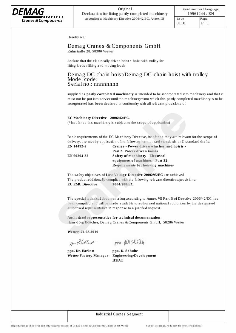
Hereby we,
Demag Cranes & Components GmbHRuhrstraße 28, 58300 Wetter
declare that the electrically driven hoist / hoist with trolley forlifting loads / lifting and moving loads
Demag DC chain hoist/Demag DC chain hoist with trolleyModel code: Serial no.: nnnnnnnn
supplied as partly completed machinery is intended to be incorporated into machinery and that itmust not be put into serviceuntil the machinery* into which this partly completed machinery is to beincorporated has been declared in conformity with all relevant provisions of
EC Machinery Directive 2006/42/EC.(* insofar as this machinery is subject to the scope of application)
Basic requirements of the EC Machinery Directive, insofar as they are relevant for the scope ofdelivery, are met by application ofthe following harmonised standards or C standard drafts:EN 14492-2 Cranes - Power driven winches and hoists -
Part 2: Power driven hoistsEN 60204-32 Safety of machinery - Electrical
equipment of machines - Part 32:Requirements for hoisting machines
The safety objectives of Low Voltage Directive 2006/95/EC are achievedThe product additionally complies with the following relevant directives/provisions:EC EMC Directive 2004/108/EC
The special technical documentation according to Annex VII Part B of Directive 2006/42/EC hasbeen compiled and will be made available to authorised national authorities by the designatedauthorised representative in response to a justified request.
Authorised representative for technical documentationHans-Jörg Böttcher, Demag Cranes & Components GmbH, 58286 Wetter
Wetter, 24.08.2010
ppa. Dr. Harkort ppa. D. SchulteWetter Factory Manager Engineering/Development
HT/AT
Industrial Cranes Segment
Reproduction in whole or in part only with prior consent of Demag Cranes & Components GmbH, 58286 Wetter Subject to change. No liability for errors or omissions
Ident. number / Language
19961244 / ENIssue Page
0110 1/ 1
OriginalDeclaration for fitting partly completed machinery
according to Machinery Directive 2006/42/EC, Annex IIB

Prin
ted
in G
erm
any
Reproduction in whole or in part only with prior consent of Demag Cranes & Components GmbH, 58286 Wetter (Germany) Subject to change. Not liable for errors or omissions.
The current addresses of the sales offices in Germany and the subsidiaries and agencies worldwide can be found on the Demag Cranes & Components homepage atwww.demagcranes.com/Contact