Embed Size (px)
DESCRIPTION
tecra a6.pdf
Citation preview
[CONFIDENTIAL]
Toshiba Personal Computer
Tecra A6
Maintenance Manual
TOSHIBA CORPORATION
ii [CONFIDENTIAL] Tecra A6 Maintenance Manual
Copyright
© 2006 by Toshiba Corporation. All rights reserved. Under the copyright laws, this manual cannot be reproduced in any form without the prior written permission of Toshiba. No patent liability is assumed with respect to the use of the information contained herein.
Toshiba Personal Computer Tecra A6 Maintenance Manual
First edition January 2006
Disclaimer
The information presented in this manual has been reviewed and validated for accuracy. The included set of instructions and descriptions are accurate for the A6 Series at the time of this manual's production. However, succeeding computers and manuals are subject to change without notice. Therefore, Toshiba assumes no liability for damages incurred directly or indirectly from errors, omissions, or discrepancies between any succeeding product and this manual.
Trademarks
IBM is a registered trademark, and OS/2 and PS/2 are trademarks of IBM Corporation. Microsoft, MS-DOS, Windows, DirectSound and DirectMusic are registered trademarks of Microsoft Corporation. Intel and Pentium are registered trademarks, and SpeedStep is a trademark of Intel Corporation. Sound Blaster is a registered trademark of Creative Technology Ltd. Centronics is a registered trademark of Centronics Data Computer Corporation. Photo CD is a trademark of Eastman Kodak. All other properties are trademarks or registered trademarks of their respective holders.
Tecra A6 Maintenance Manual [CONFIDENTIAL] iii
Preface
This maintenance manual describes how to perform hardware service maintenance for the Toshiba Personal Computer Tecra A6, referred to as the A6 Series in this manual.
The procedures described in this manual are intended to help service technicians isolate faulty Field Replaceable Units (FRUs) and replace them in the field.
SAFETY PRECAUTIONS
Four types of messages are used in this manual to bring important information to your attention. Each of these messages will be italicized and identified as shown below.
DANGER: “Danger” indicates the existence of a hazard that could result in death or serious bodily injury if the safety instruction is not observed.
WARNING: “Warning” indicates the existence of a hazard that could result in bodily injury if the safety instruction is not observed.
CAUTION: “Caution” indicates the existence of a hazard that could result in property damage if the safety instruction is not observed.
NOTE: “Note” contains general information that relates to your safe maintenance service.
Improper repair of the computer may result in safety hazards. Toshiba requires service technicians and authorized dealers or service providers to ensure the following safety precautions are adhered to strictly.
? Be sure to fasten screws securely with the right screwdriver. If a screw is not fully fastened, it could come loose, creating a danger of a short circuit, which could cause overheating, smoke or fire.
? If you replace the battery pack or RTC battery, be sure to use only the same model battery or an equivalent battery recommended by Toshiba. Installation of the wrong battery can cause the battery to explode.
iv [CONFIDENTIAL] Tecra A6 Maintenance Manual
The manual is divided into the following parts:
Chapter 1 Hardware Overview describes the A6 Series system unit and each FRU.
Chapter 2 Troubleshooting Procedures explains how to diagnose and resolve FRU problems.
Chapter 3 Test and Diagnostics describes how to perform test and diagnostic operations for maintenance service.
Chapter 4 Replacement Procedures describes the removal and replacement of the FRUs.
Appendices The appendices describe the following:
? Handling the LCD module ? Board layout ? Pin assignments ? Keyboard scan/character codes ? Key layout ? Screw torque list ? Reliability
Tecra A6 Maintenance Manual [CONFIDENTIAL] v
Conventions
This manual uses the following formats to describe, identify, and highlight terms and operating procedures.
Acronyms
On the first appearance and whenever necessary for clarification, acronyms are enclosed in parentheses following their definition. For example:
Read Only Memory (ROM)
Keys
Keys are used in the text to describe many operations. The key top symbol as it appears on the keyboard is printed in boldface type.
Key operation
Some operations require you to simultaneously use two or more keys. We identify such operations by the key top symbols separated by a plus (+) sign. For example, Ctrl + Pause (Break) means you must hold down Ctrl and at the same time press Pause (Break). If three keys are used, hold down the first two and at the same time press the third.
User input
Text that you are instructed to type in is shown in the boldface type below:
DISKCOPY A: B:
The display
Text generated by the computer that appears on its display is presented in the typeface below:
Format complete System transferred

vi [CONFIDENTIAL] Tecra A6 Maintenance Manual
Tecra A6 Maintenance Manual [CONFIDENTIAL] vii
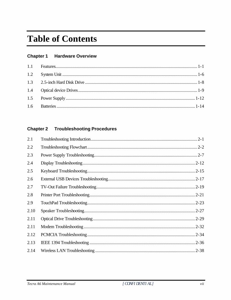
Table of Contents
Chapter 1 Hardware Overview
1.1 Features............................................................................................................................. 1-1
1.2 System Unit ....................................................................................................................... 1-6
1.3 2.5-inch Hard Disk Drive ................................................................................................... 1-8
1.4 Optical device Drives......................................................................................................... 1-9
1.5 Power Supply.................................................................................................................. 1-12
1.6 Batteries .......................................................................................................................... 1-14
Chapter 2 Troubleshooting Procedures
2.1 Troubleshooting Introduction.............................................................................................. 2-1
2.2 Troubleshooting Flowchart ................................................................................................. 2-2
2.3 Power Supply Troubleshooting........................................................................................... 2-7
2.4 Display Troubleshooting................................................................................................... 2-12
2.5 Keyboard Troubleshooting............................................................................................... 2-15
2.6 External USB Devices Troubleshooting............................................................................. 2-17
2.7 TV-Out Failure Troubleshooting....................................................................................... 2-19
2.8 Printer Port Troubleshooting............................................................................................. 2-21
2.9 TouchPad Troubleshooting............................................................................................... 2-23
2.10 Speaker Troubleshooting.................................................................................................. 2-27
2.11 Optical Drive Troubleshooting.......................................................................................... 2-29
2.11 Modem Troubleshooting .................................................................................................. 2-32
2.12 PCMCIA Troubleshooting............................................................................................... 2-34
2.13 IEEE 1394 Troubleshooting ............................................................................................. 2-36
2.14 Wireless LAN Troubleshooting ........................................................................................ 2-38
viii [CONFIDENTIAL] Tecra A6 Maintenance Manual
Chapter 3 Tests and Diagnostics
3.1 The Diagnostic Test............................................................................................................3-1
3.2 Executing the Diagnostic Test..............................................................................................3-2
3.3 Config Check Test..............................................................................................................3-6
3.4 DMI Check Test ................................................................................................................3-7
3.5 PIO Loopback Test ...........................................................................................................3-8
3.6 Speaker Audio Test............................................................................................................3-9
3.7 Fan ON/OFF Test ...........................................................................................................3-10
3.8 Main Battery Charge Test.................................................................................................3-11
3.9 FDD Test.........................................................................................................................3-12
3.10 CD-ROM Test.................................................................................................................3-13
3.11 Keyboard Test .................................................................................................................3-14
3.12 Mouse (Pad) Test.............................................................................................................3-16
3.13 LCD Pixels Mode Test.....................................................................................................3-18
3.14 Lid Switch Test ................................................................................................................3-19
3.15 HDD R/W Test ................................................................................................................3-20
3.16 LAN Test.........................................................................................................................3-22
3.17 RTC Test .........................................................................................................................3-24
Tecra A6 Maintenance Manual [CONFIDENTIAL] ix
Chapter 4 Replacement Procedures
4.1 General.............................................................................................................................. 4-4
4.2 Battery............................................................................................................................... 4-9
4.3 PC Card.......................................................................................................................... 4-11
4.4 HDD ............................................................................................................................... 4-13
4.5 Expansion Memory.......................................................................................................... 4-15
4.6 Optical Drive Module....................................................................................................... 4-18
4.7 Optical Drive ................................................................................................................... 4-20
4.8 Keyboard ........................................................................................................................ 4-22
4.9 Bluetooth module ............................................................................................................. 4-25
4.10 Wireless LAN Unit .......................................................................................................... 4-27
4.11 Modem............................................................................................................................ 4-30
4.12 Display Assembly............................................................................................................. 4-33
4.13 Top Cover....................................................................................................................... 4-35
4.14 Touch Pad....................................................................................................................... 4-37
4.15 Direct Play Button Module ............................................................................................... 4-39
4.16 Memory........................................................................................................................... 4-41
4.17 System Board.................................................................................................................. 4-42
4.18 Fan & CPU..................................................................................................................... 4-45
4.19 USB Module ................................................................................................................... 4-48
4.20 VGA Module................................................................................................................... 4-49
4.21 Display Mask................................................................................................................... 4-50
4.22 Speakers ......................................................................................................................... 4-52
4.23 FL Inverter Board............................................................................................................ 4-53
4.24 LCD Module ................................................................................................................... 4-54
x [CONFIDENTIAL] Tecra A6 Maintenance Manual
Appendices
Appendix A Handling the LCD Module.....................................................................................A-1
Appendix B Board Layout ........................................................................................................B-1
Appendix C Pin Assignments.....................................................................................................C-1
Appendix D Keyboard Scan/Character Codes ..........................................................................D-1
Appendix E Key Layout ........................................................................................................... E-1
Appendix F Series Screw Torque List....................................................................................... F-1
Appendix G Reliability...............................................................................................................G-1
Chapter 1 Hardware Overview 1
[CONFIDENTIAL]
1 Hardware Overview
1-ii [CONFIDENTIAL] Tecra A6 Maintenance Manual
1 Hardware Overview
Chapter 1 Contents
1.1 Features ...................................................................................................................... 1-1
1.2 System Unit................................................................................................................ 1-7
1.3 2.5-inch Hard Disk Drive........................................................................................... 1-9
1.4 Optical device Drives............................................................................................... 1-10
1.4.1 DVD-ROM & CD-RW ............................................................................. 1-10
1.4.2 DVD-ROM................................................................................................ 1-11
1.4.3 DVD Super Multi Double Layer............................................................... 1-12
1.5 Power Supply ........................................................................................................... 1-13
1.6 Batteries ................................................................................................................... 1-15
1.6.1 Main Battery.............................................................................................. 1-16
1.6.2 RTC battery ............................................................................................... 1-17
Tecra A6 Series Maintenance Manual [CONFIDENTIAL] 1-iii
1 Hardware Overview
Figures
Figure 1-1 2.5-inch HDD ............................................................... 錯誤! 尚未定義書籤。
Tables
Table 1-1 2.5-inch HDD specifications ......................................................................... 1-9 Table 1-2 DVD-ROM & CD-RW drive specifications ............................................... 1-10 Table 1-3 DVD-ROM drive specifications.................................................................. 1-11 Table 1-4 DVD Super Multi Double Layer drive specifications................................. 1-12
1-iv [CONFIDENTIAL] Tecra A6 Maintenance Manual
1.1 Features 1 Hardware Overview
1.1 Features
The Tecra A6 Series Personal Computer uses extensive Large Scale Integration (LSI), and Complementary Metal-Oxide Semiconductor (CMOS) technology extensively to provide compact size, minimum weight and high reliability. This computer incorporates the following features and benefits: CPU
• Intel Pentium M Yonah mobile dual core processor FSB 667MHz, C4E support (1.66GHz/1.83GHz/2GHz/2.16GHz/2.33GHz and higher with 31W TDP)
• Intel Pentium M Yonah mobile single core processor, FSB 667NHz, C4E support (1.66GHz/1.83GHz and higher with 31W TDP)
Chipset • Intel 945PM with ICH7M (Pentium® M + Extended Graphics model) or Intel
945GM with ICH7M (Pentium® M + Extended Graphics model + Integrated Graphics model)
• Extended Graphics: ATI Radeon X1300 64MB/128MB ATI Radeon X1400 64MB/128MB/256MB Nvidia Quadro 64M/128M
• NVIDIA GeForce Go 7300 (64MB or 128MB) • Realtek 861 Audio • TI 7412 for PCMCIA, 6-in 1 Multimedia Card Reader, and IEEE 1394 controller
Intel Enkron-R 10/100 or Intel Vidalia Gigabit for LAN Display
• 14” (16:10) TFT screen with a resolution of 1280 horizontal x 800 vertical pixels, non-CSV normal brightness, WXGA
• 14.1” (16:10) TFT screen with a resolution of 1280 horizontal x 800 vertical pixels, CSV normal brightness, WXGA
• 14.1” (16:10) TFT screen with a resolution of 1440 horizontal x 900 vertical pixels, CSV high brightness, WXGA
Memory • No on-board memory • DDR-II 533/667MHz at FCS supported • Dual channel support • Two SODIMM with 256MB/512MB/1GB modules • Easy upgrade from bottom of the chassis • Maximum 2GB
Tecra A6 Series Maintenance Manual [CONFIDENTIAL] 1-1
1 Hardware Overview 1.1 Features
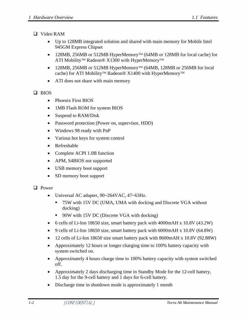
Video RAM • Up to 128MB integrated solution and shared with main memory for Mobile Intel
945GM Express Chipset • 128MB, 256MB or 512MB HyperMemoryTM (64MB or 128MB for local cache) for
ATI MobilityTM Radeon® X1300 with HyperMemoryTM • 128MB, 256MB or 512MB HyperMemoryTM (64MB, 128MB or 256MB for local
cache) for ATI MobilityTM Radeon® X1400 with HyperMemoryTM • ATI does not share with main memory
BIOS • Phoenix First BIOS • 1MB Flash ROM for system BIOS • Suspend to RAM/Disk • Password protection (Power on, supervisor, HDD) • Windows 98 ready with PnP • Various hot keys for system control • Refreshable • Complete ACPI 1.0B function • APM, S4BIOS not supported • USB memory boot support • SD memory boot support
Power • Universal AC adapter, 90~264VAC, 47~63Hz. 75W with 15V DC (UMA, UMA with docking and Discrete VGA without
docking) 90W with 15V DC (Discrete VGA with docking)
• 6 cells of Li-Ion 18650 size, smart battery pack with 4000mAH x 10.8V (43.2W) • 9 cells of Li-Ion 18650 size, smart battery pack with 6000mAH x 10.8V (64.8W) • 12 cells of Li-Ion 18650 size smart battery pack with 8600mAH x 10.8V (92.88W) • Approximately 12 hours or longer charging time to 100% battery capacity with
system switched on. • Approximately 4 hours charge time to 100% battery capacity with system switched
off. • Approximately 2 days discharging time in Standby Mode for the 12-cell battery,
1.5 day for the 9-cell battery and 1 days for 6-cell battery. • Discharge time in shutdown mode is approximately 1 month
1-2 [CONFIDENTIAL] Tecra A6 Maintenance Manual
1.1 Features 1 Hardware Overview
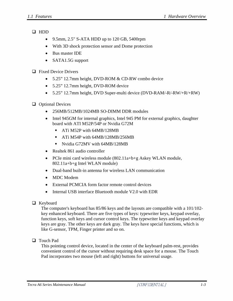
HDD • 9.5mm, 2.5" S-ATA HDD up to 120 GB, 5400rpm • With 3D shock protection sensor and Dome protection • Bus master IDE • SATA1.5G support
Fixed Device Drivers • 5.25” 12.7mm height, DVD-ROM & CD-RW combo device • 5.25” 12.7mm height, DVD-ROM device • 5.25” 12.7mm height, DVD Super-multi device (DVD-RAM/-R/-RW/+R/+RW)
Optional Devices • 256MB/512MB/1024MB SO-DIMM DDR modules • Intel 945GM for internal graphics, Intel 945 PM for external graphics, daughter
board with ATI M52P/54P or Nvidia G72M ATi M52P with 64MB/128MB ATi M54P with 64MB/128MB/256MB Nvidia G72MV with 64MB/128MB
• Realtek 861 audio controller • PCIe mini card wireless module (802.11a+b+g Askey WLAN module,
802.11a+b+g Intel WLAN module) • Dual-band built-in antenna for wireless LAN communication • MDC Modem • External PCMCIA form factor remote control devices • Internal USB interface Bluetooth module V2.0 with EDR
Keyboard The computer's keyboard has 85/86 keys and the layouts are compatible with a 101/102-key enhanced keyboard. There are five types of keys: typewriter keys, keypad overlay, function keys, soft keys and cursor control keys. The typewriter keys and keypad overlay keys are gray. The other keys are dark gray. The keys have special functions, which is like G-sensor, TPM, Finger printer and so on.
Touch Pad This pointing control device, located in the center of the keyboard palm-rest, provides convenient control of the cursor without requiring desk space for a mouse. The Touch Pad incorporates two mouse (left and right) buttons for universal usage.
Tecra A6 Series Maintenance Manual [CONFIDENTIAL] 1-3
1 Hardware Overview 1.1 Features
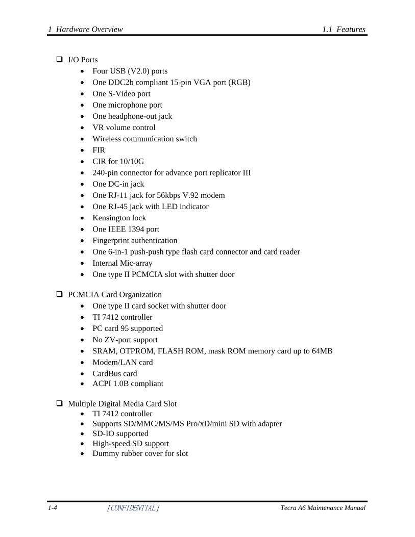
I/O Ports • Four USB (V2.0) ports • One DDC2b compliant 15-pin VGA port (RGB) • One S-Video port • One microphone port • One headphone-out jack • VR volume control • Wireless communication switch • FIR • CIR for 10/10G • 240-pin connector for advance port replicator III • One DC-in jack • One RJ-11 jack for 56kbps V.92 modem • One RJ-45 jack with LED indicator • Kensington lock • One IEEE 1394 port • Fingerprint authentication • One 6-in-1 push-push type flash card connector and card reader • Internal Mic-array • One type II PCMCIA slot with shutter door
PCMCIA Card Organization • One type II card socket with shutter door • TI 7412 controller • PC card 95 supported • No ZV-port support • SRAM, OTPROM, FLASH ROM, mask ROM memory card up to 64MB • Modem/LAN card • CardBus card • ACPI 1.0B compliant
Multiple Digital Media Card Slot • TI 7412 controller • Supports SD/MMC/MS/MS Pro/xD/mini SD with adapter • SD-IO supported • High-speed SD support • Dummy rubber cover for slot
1-4 [CONFIDENTIAL] Tecra A6 Maintenance Manual
1.1 Features 1 Hardware Overview
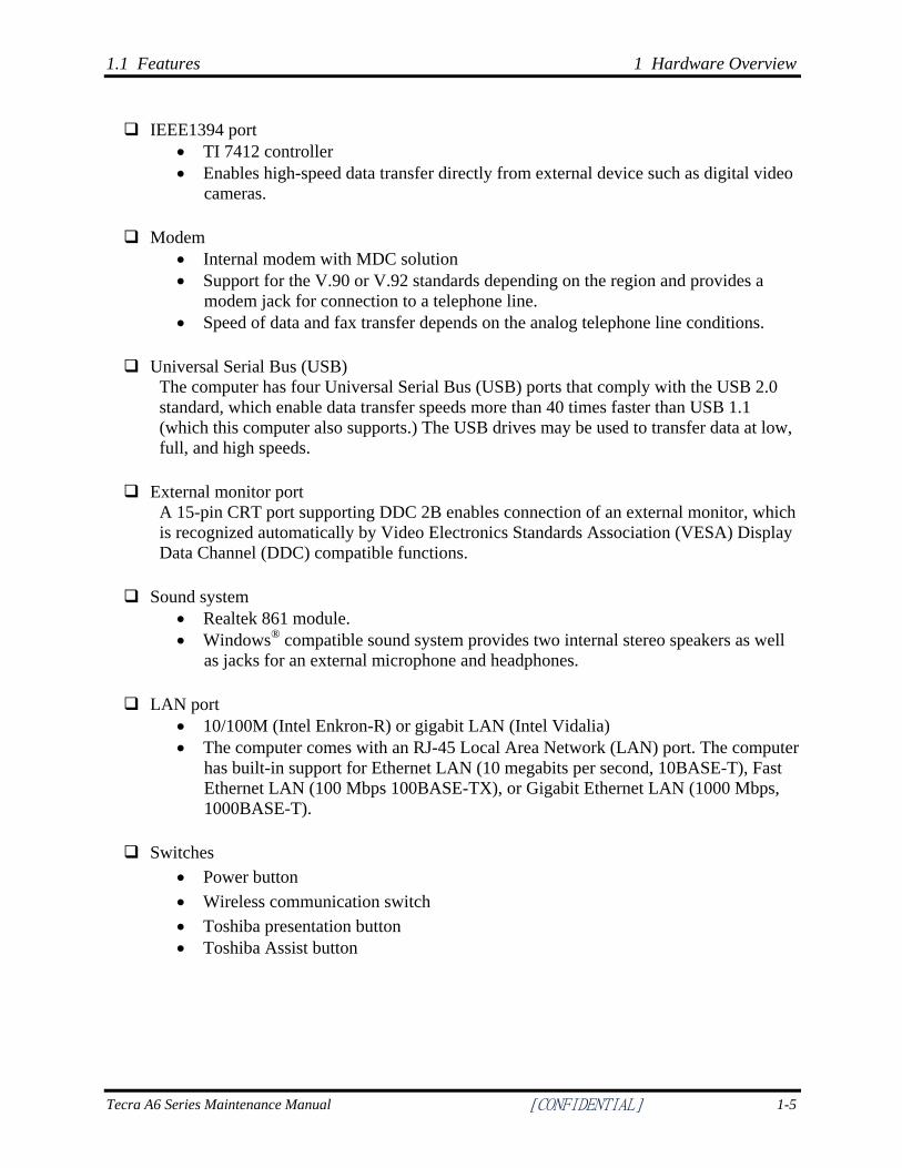
IEEE1394 port • TI 7412 controller • Enables high-speed data transfer directly from external device such as digital video
cameras.
Modem • Internal modem with MDC solution • Support for the V.90 or V.92 standards depending on the region and provides a
modem jack for connection to a telephone line. • Speed of data and fax transfer depends on the analog telephone line conditions.
Universal Serial Bus (USB) The computer has four Universal Serial Bus (USB) ports that comply with the USB 2.0 standard, which enable data transfer speeds more than 40 times faster than USB 1.1 (which this computer also supports.) The USB drives may be used to transfer data at low, full, and high speeds.
External monitor port A 15-pin CRT port supporting DDC 2B enables connection of an external monitor, which is recognized automatically by Video Electronics Standards Association (VESA) Display Data Channel (DDC) compatible functions.
Sound system • Realtek 861 module. • Windows® compatible sound system provides two internal stereo speakers as well
as jacks for an external microphone and headphones.
LAN port • 10/100M (Intel Enkron-R) or gigabit LAN (Intel Vidalia) • The computer comes with an RJ-45 Local Area Network (LAN) port. The computer
has built-in support for Ethernet LAN (10 megabits per second, 10BASE-T), Fast Ethernet LAN (100 Mbps 100BASE-TX), or Gigabit Ethernet LAN (1000 Mbps, 1000BASE-T).
Switches • Power button • Wireless communication switch • Toshiba presentation button • Toshiba Assist button
Tecra A6 Series Maintenance Manual [CONFIDENTIAL] 1-5
1 Hardware Overview 1.1 Features
Bluetooth module Some computers in this series are equipped with Bluetooth functionality (Version 2.0 + EDR) with antenna. Bluetooth is a short-range wireless technology used to create PANs (Personal Area Networks) among your devices, as well as with other nearby devices such as cell phones and digital cameras.
Excellent power management function • Standby mode, Suspend to RAM or Suspend to disk mode, using time out or hot
key • HDD local standby mode by time out • LCD local standby mode by time out • Low battery alarm by beep • Auto-backlight off when LCD cover closed • Full ACPI 1.0B supported • LCD auto-dim mode by time out
1-6 [CONFIDENTIAL] Tecra A6 Maintenance Manual
1.2 System Unit 1 Hardware Overview
1.2 System Unit
The system unit is composed of the following major components: Processor (depending on the model you purchased)
• Intel Pentium M Yonah mobile dual core processor T2300/T2400/T2500/T2600 • Intel Pentium M Yonah mobile single core processor T1300/T1400
System Logic • Intel 945PM with ICH7M (Pentium® M + Extended Graphics model) or Intel
945GM with ICH7M (Pentium® M + Extended Graphics model + Integrated Graphics model)
• Extended Graphics: ATI Radeon X1300 64MB/128MB ATI Radeon X1400 64MB/128MB/256MB Nvidia Quadro 64M/128M
• NVIDIA GeForce Go 7300 (64MB or 128MB) • Realtek 861 Audio • TI 7412 for PCMCIA, 6-in 1 Multimedia Card Reader, and IEEE 1394 controller
Intel Enkron-R 10/100 or Intel Vidalia Gigabit for LAN • PCI express • Power management functions • Supports DMI
Memory • No on-board memory • ROM BIOS for system • 1MB Flash ROM • DDR-II 533/667MHz at FCS supported • Dual channel support • Easy upgrade (Maximum 2GB) from bottom of the chassis • Two JEDEC standard 200-pin, 1.8V DDR II SO-DIMM memory support for
256MB/512MB/1024MB/2048MB. • Slot: 2 SO-DIMM up to 1GB can be upgraded through memory expansion slot.
You need to remove existing SO-DIMM if SO-DIMM is installed in memory expansion slot. Maximum upgradeable system memory depends on the model.
Tecra A6 Series Maintenance Manual [CONFIDENTIAL] 1-7
1 Hardware Overview 1.2 System Unit
Video RAM • Up to 128MB integrated solution and shared with main memory for Mobile Intel
945GM Express Chipset • 128MB, 256MB or 512MB HyperMemoryTM (64MB or 128MB for local cache) for
ATI MobilityTM Radeon® X1300 with HyperMemoryTM • 128MB, 256MB or 512MB HyperMemoryTM (64MB, 128MB or 256MB for local
cache) for ATI MobilityTM Radeon® X1400 with HyperMemoryTM • ATI does not share with main memory
Audio subsystem • Realtek 861 Audio
− Microphone-in and headphone-out − Internal Microphone array − Two stereo speakers − Sound effect by SRS software − Driver level support for all applications by Toshiba virtual sound − Volume control: Dial type for Win XP − Stereo speakers with box or Harman/kardon(Odessey2)
1-8 [CONFIDENTIAL] Tecra A6 Maintenance Manual
1.4 Optical device Drives 1 Hardware Overview
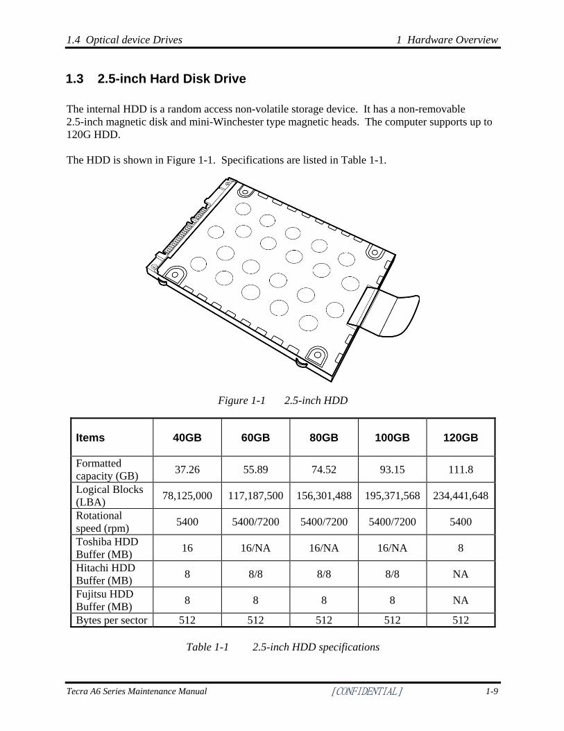
1.3 2.5-inch Hard Disk Drive
The internal HDD is a random access non-volatile storage device. It has a non-removable 2.5-inch magnetic disk and mini-Winchester type magnetic heads. The computer supports up to 120G HDD. The HDD is shown in Figure 1-1. Specifications are listed in Table 1-1.
Figure 1-1 2.5-inch HDD
Items 40GB 60GB 80GB 100GB 120GB
Formatted capacity (GB) 37.26 55.89 74.52 93.15 111.8
Logical Blocks (LBA) 78,125,000 117,187,500 156,301,488 195,371,568 234,441,648
Rotational speed (rpm) 5400 5400/7200 5400/7200 5400/7200 5400
Toshiba HDD Buffer (MB) 16 16/NA 16/NA 16/NA 8
Hitachi HDD Buffer (MB) 8 8/8 8/8 8/8 NA
Fujitsu HDD Buffer (MB) 8 8 8 8 NA
Bytes per sector 512 512 512 512 512
Table 1-1 2.5-inch HDD specifications
Tecra A6 Series Maintenance Manual [CONFIDENTIAL] 1-9
1 Hardware Overview 1.4 Optical device Drives
1.4 Optical device Drives
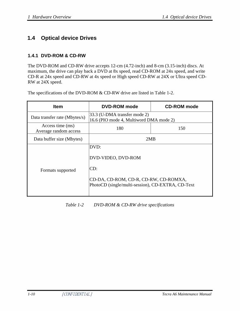
1.4.1 DVD-ROM & CD-RW
The DVD-ROM and CD-RW drive accepts 12-cm (4.72-inch) and 8-cm (3.15-inch) discs. At maximum, the drive can play back a DVD at 8x speed, read CD-ROM at 24x speed, and write CD-R at 24x speed and CD-RW at 4x speed or High speed CD-RW at 24X or Ultra speed CD-RW at 24X speed. The specifications of the DVD-ROM & CD-RW drive are listed in Table 1-2.
Item DVD-ROM mode CD-ROM mode
Data transfer rate (Mbytes/s) 33.3 (U-DMA transfer mode 2) 16.6 (PIO mode 4, Multiword DMA mode 2)
Access time (ms) Average random access 180 150
Data buffer size (Mbytes) 2MB
Formats supported
DVD: DVD-VIDEO, DVD-ROM
CD: CD-DA, CD-ROM, CD-R, CD-RW, CD-ROMXA, PhotoCD (single/multi-session), CD-EXTRA, CD-Text
Table 1-2 DVD-ROM & CD-RW drive specifications
1-10 [CONFIDENTIAL] Tecra A6 Maintenance Manual
1.4 Optical device Drives 1 Hardware Overview
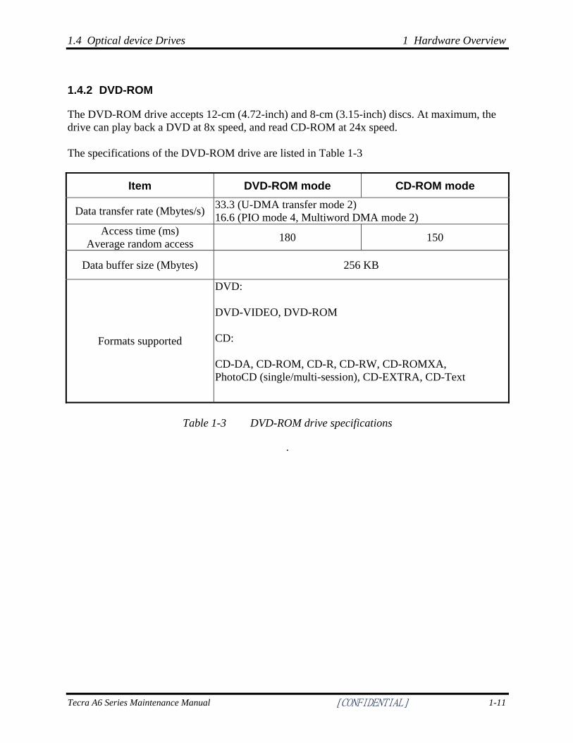
1.4.2 DVD-ROM
The DVD-ROM drive accepts 12-cm (4.72-inch) and 8-cm (3.15-inch) discs. At maximum, the drive can play back a DVD at 8x speed, and read CD-ROM at 24x speed. The specifications of the DVD-ROM drive are listed in Table 1-3
Item DVD-ROM mode CD-ROM mode
Data transfer rate (Mbytes/s) 33.3 (U-DMA transfer mode 2) 16.6 (PIO mode 4, Multiword DMA mode 2)
Access time (ms) Average random access 180 150
Data buffer size (Mbytes) 256 KB
Formats supported
DVD: DVD-VIDEO, DVD-ROM
CD: CD-DA, CD-ROM, CD-R, CD-RW, CD-ROMXA, PhotoCD (single/multi-session), CD-EXTRA, CD-Text
Table 1-3 DVD-ROM drive specifications
.
Tecra A6 Series Maintenance Manual [CONFIDENTIAL] 1-11
1 Hardware Overview 1.4 Optical device Drives
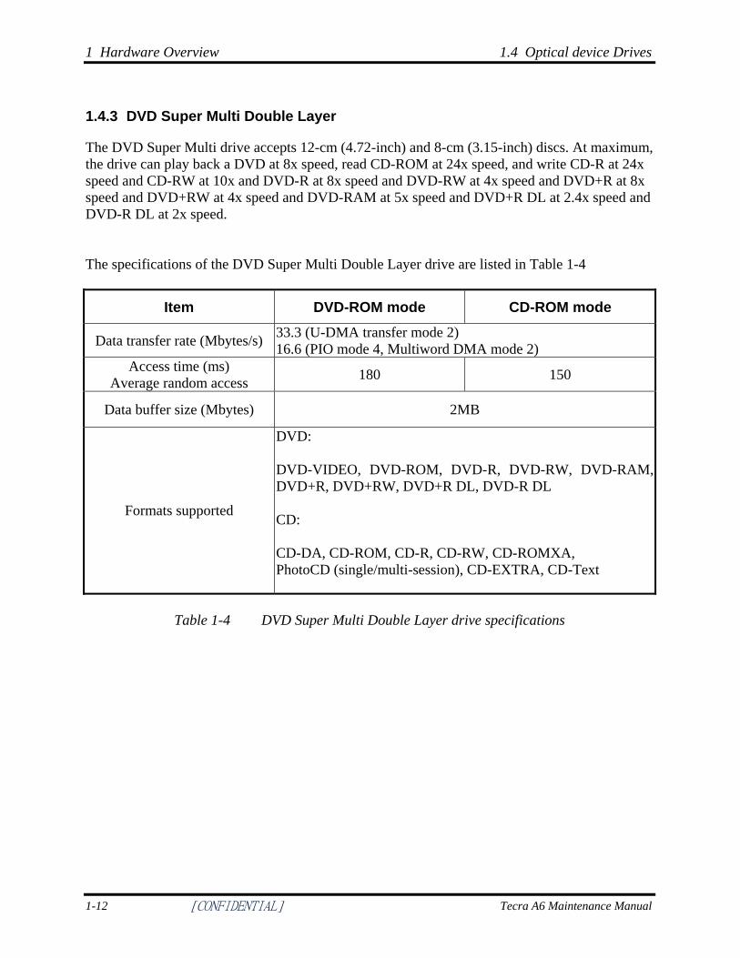
1.4.3 DVD Super Multi Double Layer
The DVD Super Multi drive accepts 12-cm (4.72-inch) and 8-cm (3.15-inch) discs. At maximum, the drive can play back a DVD at 8x speed, read CD-ROM at 24x speed, and write CD-R at 24x speed and CD-RW at 10x and DVD-R at 8x speed and DVD-RW at 4x speed and DVD+R at 8x speed and DVD+RW at 4x speed and DVD-RAM at 5x speed and DVD+R DL at 2.4x speed and DVD-R DL at 2x speed. The specifications of the DVD Super Multi Double Layer drive are listed in Table 1-4
Item DVD-ROM mode CD-ROM mode
Data transfer rate (Mbytes/s) 33.3 (U-DMA transfer mode 2) 16.6 (PIO mode 4, Multiword DMA mode 2)
Access time (ms) Average random access 180 150
Data buffer size (Mbytes) 2MB
Formats supported
DVD: DVD-VIDEO, DVD-ROM, DVD-R, DVD-RW, DVD-RAM,DVD+R, DVD+RW, DVD+R DL, DVD-R DL
CD: CD-DA, CD-ROM, CD-R, CD-RW, CD-ROMXA, PhotoCD (single/multi-session), CD-EXTRA, CD-Text
Table 1-4 DVD Super Multi Double Layer drive specifications
1-12 [CONFIDENTIAL] Tecra A6 Maintenance Manual
1.5 Power Supply 1 Hardware Overview
1.5 Power Supply
This specification defines the performance and characteristics of the 75W AC adapter power supply. It supplies a constant voltage 15V output source for Tecra A6 series notebook computer. A/D conversion
• The EC uses 10-bit sampling for A/D conversion to determine the following values: – Battery and temperature
AC adaptor and battery check • The EC checks the following by A/D converted values:
– Battery installed • The EC checks the following by GPIO values:
– AC adaptor connected
Abnormal check • The EC determines whether the condition is abnormal, and if so, stores an error
code into the error register.
Input port management • The EC monitors the following input signal status:
– System power ON/OFF status – Direct CD power ON/OFF status
Beep and LED control • Beep is caused by the low battery status. • The EC controls the following two kinds of LED
– DC IN LED (one color: green) • Green: indicates AC adaptor is connected
– Battery LED (two colors: orange and green) • Green solid: The battery is fully charged. • Orange: The computer is quick-charging the battery / the battery is low.
Power ON/OFF sequence • When power is turned on or off, the EC starts the power on or off sequence.
– SQ0-4: power ON sequence – SQ5-B: power OFF sequence
Tecra A6 Series Maintenance Manual [CONFIDENTIAL] 1-13
1 Hardware Overview 1.5 Power Supply
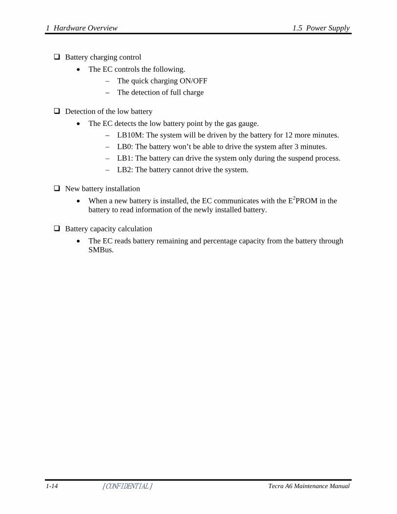
Battery charging control • The EC controls the following.
– The quick charging ON/OFF – The detection of full charge
Detection of the low battery • The EC detects the low battery point by the gas gauge.
– LB10M: The system will be driven by the battery for 12 more minutes. – LB0: The battery won’t be able to drive the system after 3 minutes. – LB1: The battery can drive the system only during the suspend process. – LB2: The battery cannot drive the system.
New battery installation • When a new battery is installed, the EC communicates with the E2PROM in the
battery to read information of the newly installed battery.
Battery capacity calculation • The EC reads battery remaining and percentage capacity from the battery through
SMBus.
1-14 [CONFIDENTIAL] Tecra A6 Maintenance Manual
1.6 Batteries 1 Hardware Overview
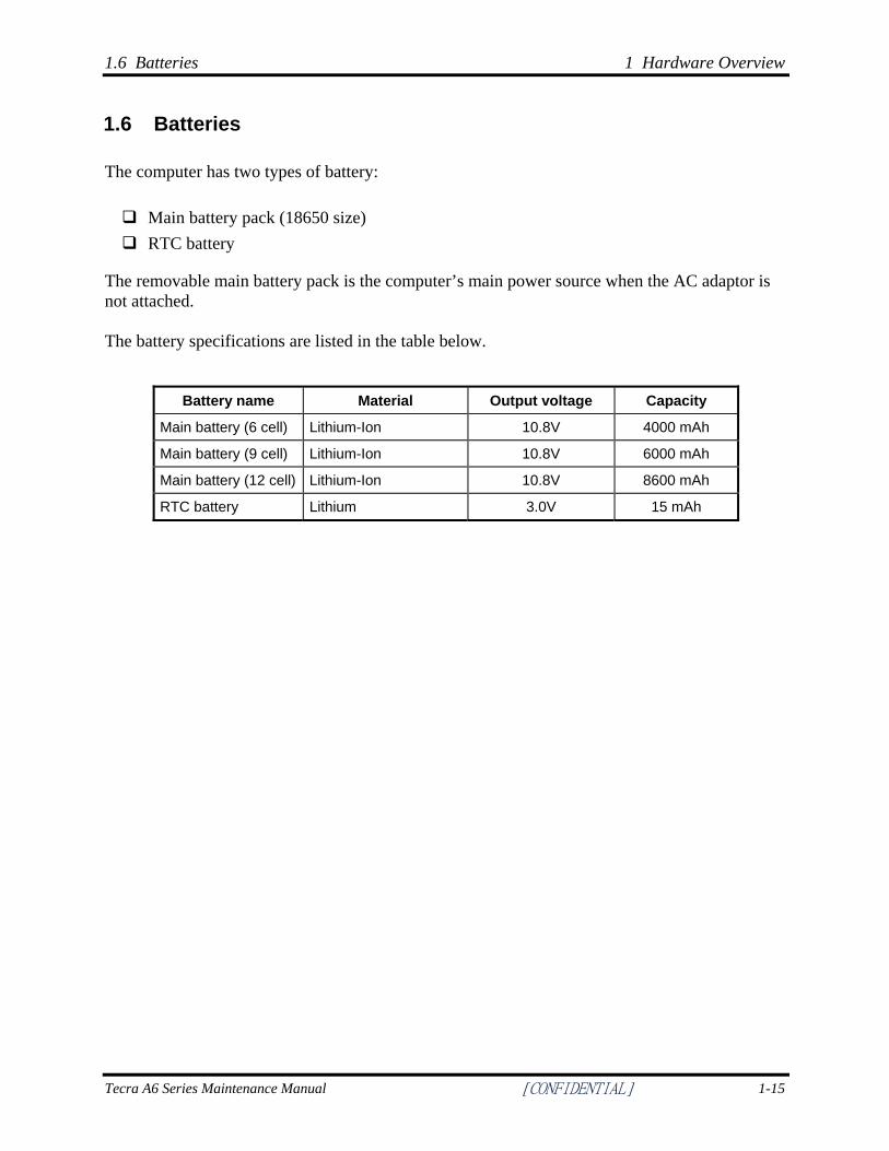
1.6 Batteries
The computer has two types of battery: Main battery pack (18650 size) RTC battery
The removable main battery pack is the computer’s main power source when the AC adaptor is not attached. The battery specifications are listed in the table below.
Battery name Material Output voltage Capacity
Main battery (6 cell) Lithium-Ion 10.8V 4000 mAh
Main battery (9 cell) Lithium-Ion 10.8V 6000 mAh
Main battery (12 cell) Lithium-Ion 10.8V 8600 mAh
RTC battery Lithium 3.0V 15 mAh
Tecra A6 Series Maintenance Manual [CONFIDENTIAL] 1-15
1 Hardware Overview 1.6 Batteries
1.6.1 Main Battery
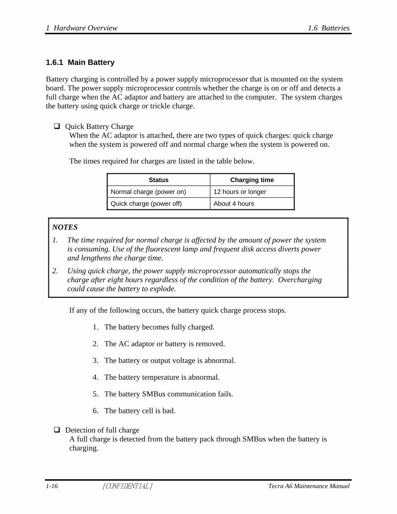
Battery charging is controlled by a power supply microprocessor that is mounted on the system board. The power supply microprocessor controls whether the charge is on or off and detects a full charge when the AC adaptor and battery are attached to the computer. The system charges the battery using quick charge or trickle charge. Quick Battery Charge
When the AC adaptor is attached, there are two types of quick charges: quick charge when the system is powered off and normal charge when the system is powered on.
The times required for charges are listed in the table below.
Status Charging time
Normal charge (power on) 12 hours or longer
Quick charge (power off) About 4 hours
NOTES
1. The time required for normal charge is affected by the amount of power the system is consuming. Use of the fluorescent lamp and frequent disk access diverts power and lengthens the charge time.
2. Using quick charge, the power supply microprocessor automatically stops the charge after eight hours regardless of the condition of the battery. Overcharging could cause the battery to explode.
If any of the following occurs, the battery quick charge process stops.
1. The battery becomes fully charged.
2. The AC adaptor or battery is removed.
3. The battery or output voltage is abnormal.
4. The battery temperature is abnormal.
5. The battery SMBus communication fails.
6. The battery cell is bad.
Detection of full charge A full charge is detected from the battery pack through SMBus when the battery is charging.
1-16 [CONFIDENTIAL] Tecra A6 Maintenance Manual
1.6 Batteries 1 Hardware Overview
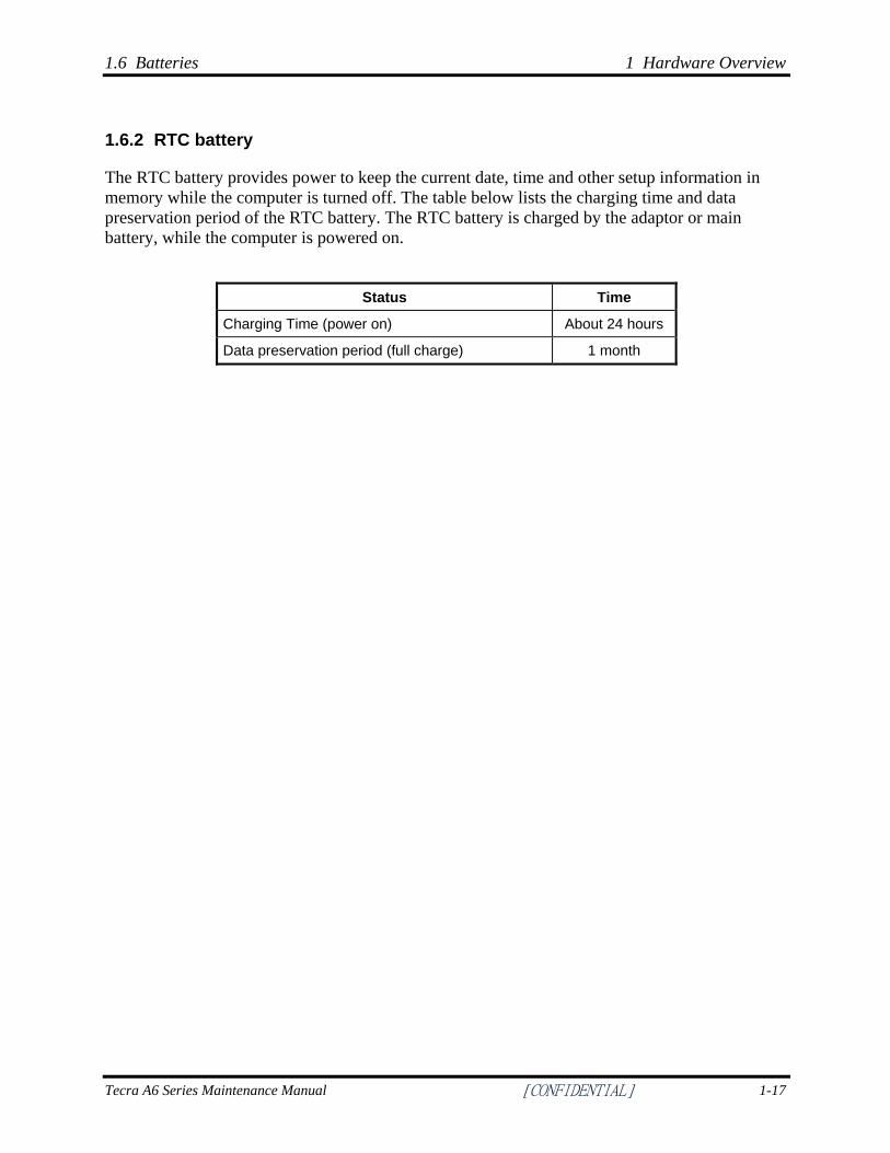
1.6.2 RTC battery
The RTC battery provides power to keep the current date, time and other setup information in memory while the computer is turned off. The table below lists the charging time and data preservation period of the RTC battery. The RTC battery is charged by the adaptor or main battery, while the computer is powered on.
Status Time
Charging Time (power on) About 24 hours
Data preservation period (full charge) 1 month
Tecra A6 Series Maintenance Manual [CONFIDENTIAL] 1-17
Chapter 2
Troubleshooting Procedures 2
2 Troubleshooting Procedures
2-ii [CONFIDENTIAL] Tecra A6 Maintenance Manual
Chapter 2 Contents
2.1 Troubleshooting Introduction.....................................................................................2-1
2.2 Troubleshooting Flowchart ........................................................................................2-2
2.3 Power Supply Troubleshooting ..................................................................................2-7
2.4 Display Troubleshooting .............................................................................……….2-12
2.5 Keyboard Troubleshooting .......................................................................................2-15
2.6 External USB Devices Troubleshooting ..................................................................2-17
2.7 TV-Out Failure Troubleshooting..............................................................................2-19
2.8 TouchPad Troubleshooting ......................................................................................2-21
2.9 Speaker Troubleshooting..........................................................................................2-23
2.10 Optical drive troubleshooting ...................................................................................2-27
2.11 Modem Troubleshooting ..........................................................................................2-30
2.12 PCMCIA Troubleshooting .......................................................................................2-32
2.13 IEEE 1394 Troubleshooting .....................................................................................2-34
2.14 Wireless LAN Troubleshooting ...............................................................................2-36
2.15 5IN1 card troubleshooting.........................................................................................2-38
2.16 Bluetooth Troubleshooting………………………………………………….………2-40
2.17 Fingerprint Troubleshooting………………………………………………………...2-42
2.18 3D G sensor (3D HDD Protection) Troubleshooting………………………………..2-44
2 Troubleshooting Procedures
Tecra A6 Maintenance Manual [CONFIDENTIAL] 2-iii
Figures
Figure 2-1 Troubleshooting flowchart (1/2) .................................................................... 2-3
Figure 2-1 Troubleshooting flowchart (2/2) .................................................................... 2-4
Figure 2-2 Power Supply Troubleshooting Process ........................................................ 2-7
Figure 2-3 Display troubleshooting process .................................................................. 2-12
Figure 2-4 Keyboard troubleshooting process............................................................... 2-15
Figure 2-5 External USB device troubleshooting process............................................. 2-17
Figure 2-6 TV-out troubleshooting process................................................................... 2-19
Figure 2-7 TouchPad troubleshooting process .............................................................. 2-21
Figure 2-8 Speaker troubleshooting process.................................................................. 2-23
Figure 2-9 Optical drive troubleshooting process ......................................................... 2-27
Figure 2-10 Modem troubleshooting process .................................................................. 2-30
Figure 2-11 PCMCIA troubleshooting process ............................................................... 2-32
Figure 2-12 IEEE 1394 troubleshooting process ............................................................. 2-34
Figure 2-13 Wireless LAN troubleshooting process ....................................................... 2-36
Figure 2-14 6IN1 card troubleshooting process .............................................................. 2-38
Figure 2-15 Bluetooth troubleshooting process ………………………………….……2-40
Figure 2-16 Fingerprint troubleshooting process………………………………………..2-42
Figure 2-17 TPM Troubleshooting process……………………………………………...2-44
Figure 2-18 3D HDD Protection Troubleshooting process………………………………2-46
Tables
Table 2-1 Battery LED ...................................................................................................... 2-8
Table 2-2 DC-IN LED....................................................................................................... 2-9

2.1 Troubleshooting Introduction 2 Troubleshooting Procedures
Tecra A6 Maintenance Manual [CONFIDENTIAL] 2-1
2.1 Troubleshooting Introduction
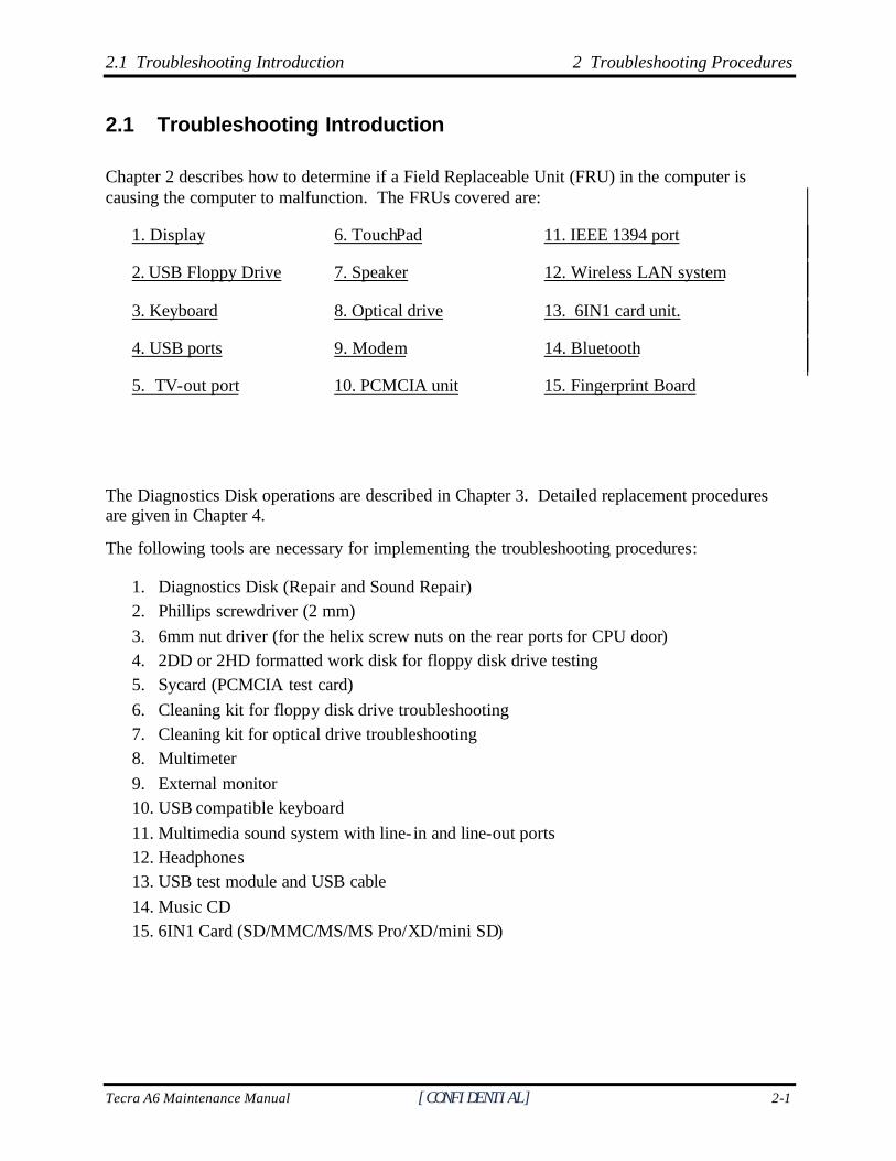
Chapter 2 describes how to determine if a Field Replaceable Unit (FRU) in the computer is causing the computer to malfunction. The FRUs covered are:
1. Display 6. TouchPad 11. IEEE 1394 port
2. USB Floppy Drive 7. Speaker 12. Wireless LAN system
3. Keyboard 8. Optical drive 13. 6IN1 card unit.
4. USB ports 9. Modem 14. Bluetooth
5. TV-out port 10. PCMCIA unit 15. Fingerprint Board
The Diagnostics Disk operations are described in Chapter 3. Detailed replacement procedures are given in Chapter 4.
The following tools are necessary for implementing the troubleshooting procedures:
1. Diagnostics Disk (Repair and Sound Repair) 2. Phillips screwdriver (2 mm) 3. 6mm nut driver (for the helix screw nuts on the rear ports for CPU door) 4. 2DD or 2HD formatted work disk for floppy disk drive testing 5. Sycard (PCMCIA test card) 6. Cleaning kit for floppy disk drive troubleshooting 7. Cleaning kit for optical drive troubleshooting 8. Multimeter 9. External monitor 10. USB compatible keyboard 11. Multimedia sound system with line- in and line-out ports 12. Headphones 13. USB test module and USB cable 14. Music CD 15. 6IN1 Card (SD/MMC/MS/MS Pro/XD/mini SD)
2 Troubleshooting Procedures 2.2 Troubleshooting Flowchart
2-2 [CONFIDENTIAL] Tecra A6 Maintenance Manual
2.2 Troubleshooting Flowchart
If you know the location of the malfunction, turn directly to the appropriate section of this chapter. If the problem is unspecified, use the flowchart in Figure 2-1 as a guide for determining which troubleshooting procedures to execute. Before performing any troubleshooting procedures, verify the following:
? Ask the user if a password is registered and, if it is, ask him or her to enter the password.
? Verify with the customer that Toshiba Windows XP is installed on the hard disk. Operating systems that were not preinstalled by Toshiba can cause the computer to malfunction.
? Make sure all optional equipment is removed from the computer.
? Make sure the floppy disk drive, if installed, is empty. If no FDD module is installed, you should use an external FDD to run the diagnostics tests
2.3 Power Supply Troubleshooting 2 Troubleshooting Procedures
Tecra A6 Maintenance Manual [CONFIDENTIAL] 2-3
S T A R T
Connect the AC adapter to the DC-IN socket
I s the DC-IN LED on?
Is the Bat tery LED on?
Turn the Power swi tch on
I s t he Power On LED on?
Is the "Toshiba" logo message display?
If the "password" message displays , typethe password, then press Enter .
I s Tosh iba Windows be ing loaded?
A
Yes
Yes
Yes
Yes
Yes
Yes
Per form the Power SupplyTroubleshooting procedures in
section 2.3
Perform diagnost ics program.Run CM165.EXE and se lec t the
H A R D D I S K i t e m .
Perform the DisplayTroubleshooting procedures in
section 2.4
Per form the Power SupplyTroubleshooting procedures in
section 2.3
Per form the Power SupplyTroubleshooting procedures in
section 2.3
No
No
No
No
No
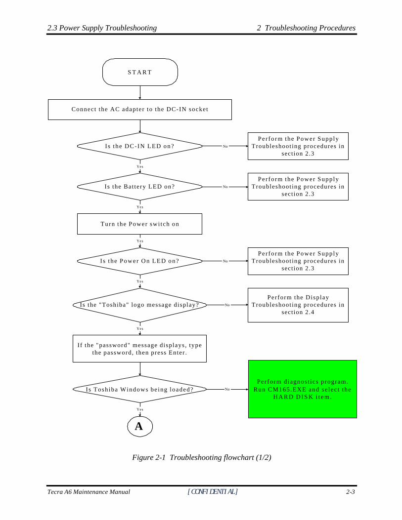
Figure 2-1 Troubleshooting flowchart (1/2)
2 Troubleshooting Procedures 2.2 Troubleshooting Flowchart
2-4 [CONFIDENTIAL] Tecra A6 Maintenance Manual
A
Does typed characters appear correctly?
Insert the diagnostics disk into the FDD.Then run the diagnostics test program.
Is the diagnostics test loaded?
Allow each test to performautomatically
Is an error detected by any of thediagnostics tests?
System is normal
End
Yes
Yes
Yes
No
Perform the KeyboardTroubleshooting procedures
in section 2.6
Perform the FDDTroubleshooting procedures
in section 2.5
After confirming whichdiagnostics test has detected
an error, perform theappropriate procedure as
outlined below.
No
No
Yes
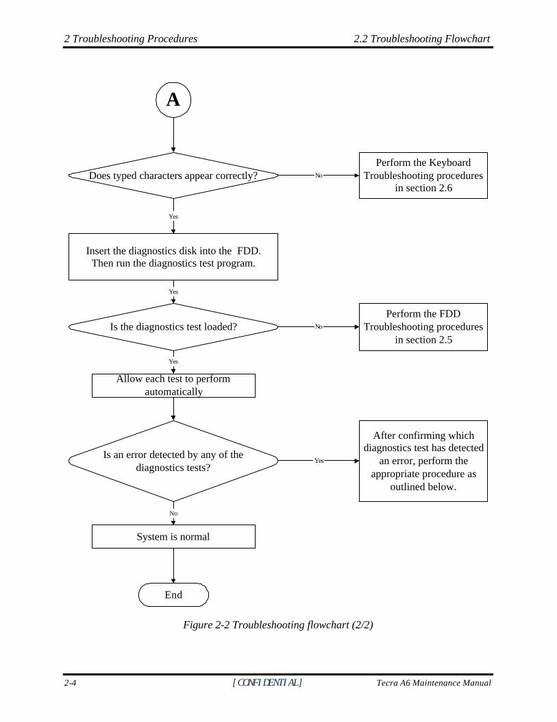
Figure 2-2 Troubleshooting flowchart (2/2)
2.3 Power Supply Troubleshooting 2 Troubleshooting Procedures
Tecra A6 Maintenance Manual [CONFIDENTIAL] 2-5
If the diagnostics program cannot detect an error, the problem may be intermittent. The test program should be executed several times to isolate the problem. When a problem has been located, perform the appropriate troubleshooting procedures as follows:
1. If an error is detected by the battery test, perform the Power Supply Troubleshooting procedures in Section 2.3.
2. If an error is detected by the display test, perform the Display Troubleshooting procedures in Section 2.4.
3. If an error is detected by the keyboard test, perform the Keyboard Troubleshooting procedures in Section 2.5.
4. If an error is detected by the TouchPad test, perform the TouchPad Troubleshooting procedures in Section 2.8.
5. If an error is detected by the audio test, perform the Speaker Troubleshooting procedures in Section 2.9 and the Optical Drive Troubleshooting Procedures in Section 2.9.
6. If an error is detected by the modem test, perform the Modem Troubleshooting Procedures in Section 2.10.
2 Troubleshooting Procedures 2.2 Troubleshooting Flowchart
2-6 [CONFIDENTIAL] Tecra A6 Maintenance Manual
Other problems that are not covered by the diagnostics program may be discovered by a user.
1. If an error is detected when using an external USB device, perform the External USB Devices Troubleshooting procedures in Section 2.6.
2. If an error is detected when using the TV-out connection, perform the TV-Out Failure Troubleshooting procedures in Section 2.7.
3. If an error is detected when using the speakers, perform the Speaker Troubleshooting procedures in Section 2.10.
4. If an error is detected when using the modem, perform the Modem Troubleshooting procedures in Section 2.12.
5. If an error is detected when using the PCMCIA unit, perform the PCMCIA Troubleshooting procedures in Section 2.13.
6. If an error is detected when using the IEEE1394 device, perform the IEEE1394 device Troubleshooting procedures in Section 2.14.
7. If an error is detected when using the Wireless LAN, perform the Wireless LAN Troubleshooting procedures in Section 2.15.
2.3 Power Supply Troubleshooting 2 Troubleshooting Procedures
Tecra A6 Maintenance Manual [CONFIDENTIAL] 2-7
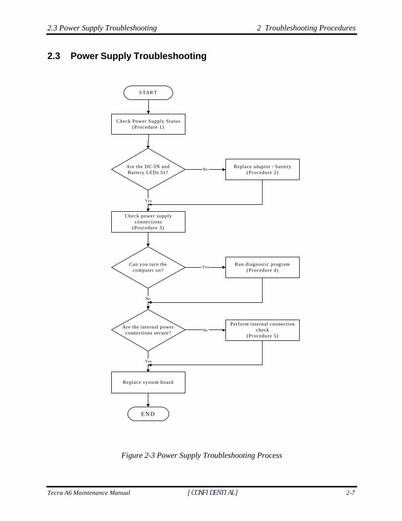
2.3 Power Supply Troubleshooting
S TAR T
Are the DC-IN andBattery LEDs lit?
Can you turn thecomputer on?
Are the internal powerconnections secure?
END
Check Power Supply Status(Procedure 1)
No
Yes
Check power supplyconnections
(Procedure 3)
Run diagnostic program(Procedure 4)
Yes
No
Replace adaptor / battery(Procedure 2)
NoPerform internal connection
check(Procedure 5)
Replace system board
Yes
Figure 2-3 Power Supply Troubleshooting Process
2 Troubleshooting Procedures 2.2 Troubleshooting Flowchart
2-8 [CONFIDENTIAL] Tecra A6 Maintenance Manual
The power supply controls many functions and components. To determine if the power supply is functioning properly, start with Procedure 1 and continue with the other Procedures as instructed. The flowchart in Figure 2-3 gives a summary of the process. The procedures described in this section are:
Procedure 1: Power status check
Procedure 2: Adaptor / battery replacement
Procedure 3: Power supply connection check
Procedure 4: Diagnostic check
Procedure 5: Internal connection check
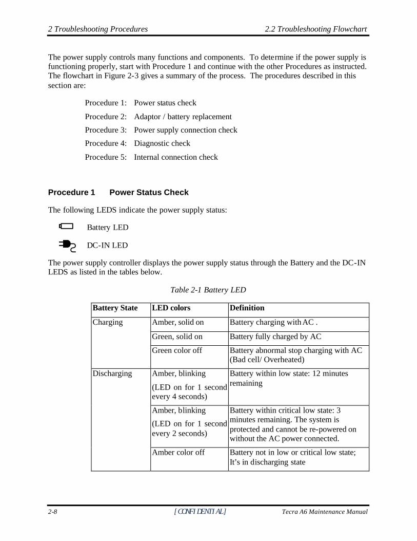
Procedure 1 Power Status Check
The following LEDS indicate the power supply status:
Battery LED
DC-IN LED
The power supply controller displays the power supply status through the Battery and the DC-IN LEDS as listed in the tables below.
Table 2-1 Battery LED
Battery State LED colors Definition
Amber, solid on Battery charging with AC .
Green, solid on Battery fully charged by AC
Charging
Green color off Battery abnormal stop charging with AC (Bad cell/ Overheated)
Amber, blinking
(LED on for 1 second every 4 seconds)
Battery within low state: 12 minutes remaining
Amber, blinking
(LED on for 1 second every 2 seconds)
Battery within critical low state: 3 minutes remaining. The system is protected and cannot be re-powered on without the AC power connected.
Discharging
Amber color off Battery not in low or critical low state; It’s in discharging state
2.3 Power Supply Troubleshooting 2 Troubleshooting Procedures
Tecra A6 Maintenance Manual [CONFIDENTIAL] 2-9
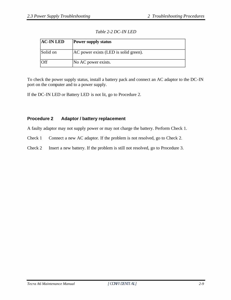
Table 2-2 DC-IN LED
AC-IN LED Power supply status
Solid on AC power exists (LED is solid green).
Off No AC power exists.
To check the power supply status, install a battery pack and connect an AC adaptor to the DC-IN port on the computer and to a power supply.
If the DC-IN LED or Battery LED is not lit, go to Procedure 2.
Procedure 2 Adaptor / battery replacement
A faulty adaptor may not supply power or may not charge the battery. Perform Check 1.
Check 1 Connect a new AC adaptor. If the problem is not resolved, go to Check 2.
Check 2 Insert a new battery. If the problem is still not resolved, go to Procedure 3.
2 Troubleshooting Procedures 2.2 Troubleshooting Flowchart
2-10 [CONFIDENTIAL] Tecra A6 Maintenance Manual
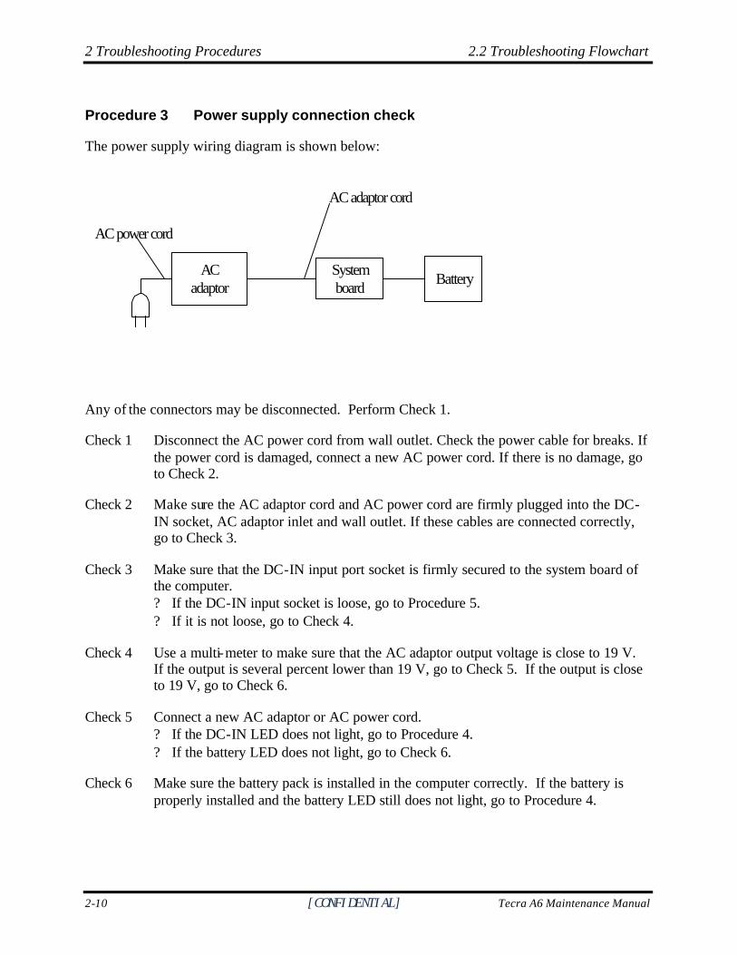
Procedure 3 Power supply connection check
The power supply wiring diagram is shown below:
ACadaptor
Systemboard Battery
AC adaptor cord
AC power cord
Any of the connectors may be disconnected. Perform Check 1.
Check 1 Disconnect the AC power cord from wall outlet. Check the power cable for breaks. If the power cord is damaged, connect a new AC power cord. If there is no damage, go to Check 2.
Check 2 Make sure the AC adaptor cord and AC power cord are firmly plugged into the DC-IN socket, AC adaptor inlet and wall outlet. If these cables are connected correctly, go to Check 3.
Check 3 Make sure that the DC-IN input port socket is firmly secured to the system board of the computer. ? If the DC-IN input socket is loose, go to Procedure 5. ? If it is not loose, go to Check 4.
Check 4 Use a multi-meter to make sure that the AC adaptor output voltage is close to 19 V. If the output is several percent lower than 19 V, go to Check 5. If the output is close to 19 V, go to Check 6.
Check 5 Connect a new AC adaptor or AC power cord. ? If the DC-IN LED does not light, go to Procedure 4. ? If the battery LED does not light, go to Check 6.
Check 6 Make sure the battery pack is installed in the computer correctly. If the battery is properly installed and the battery LED still does not light, go to Procedure 4.
2.3 Power Supply Troubleshooting 2 Troubleshooting Procedures
Tecra A6 Maintenance Manual [CONFIDENTIAL] 2-11
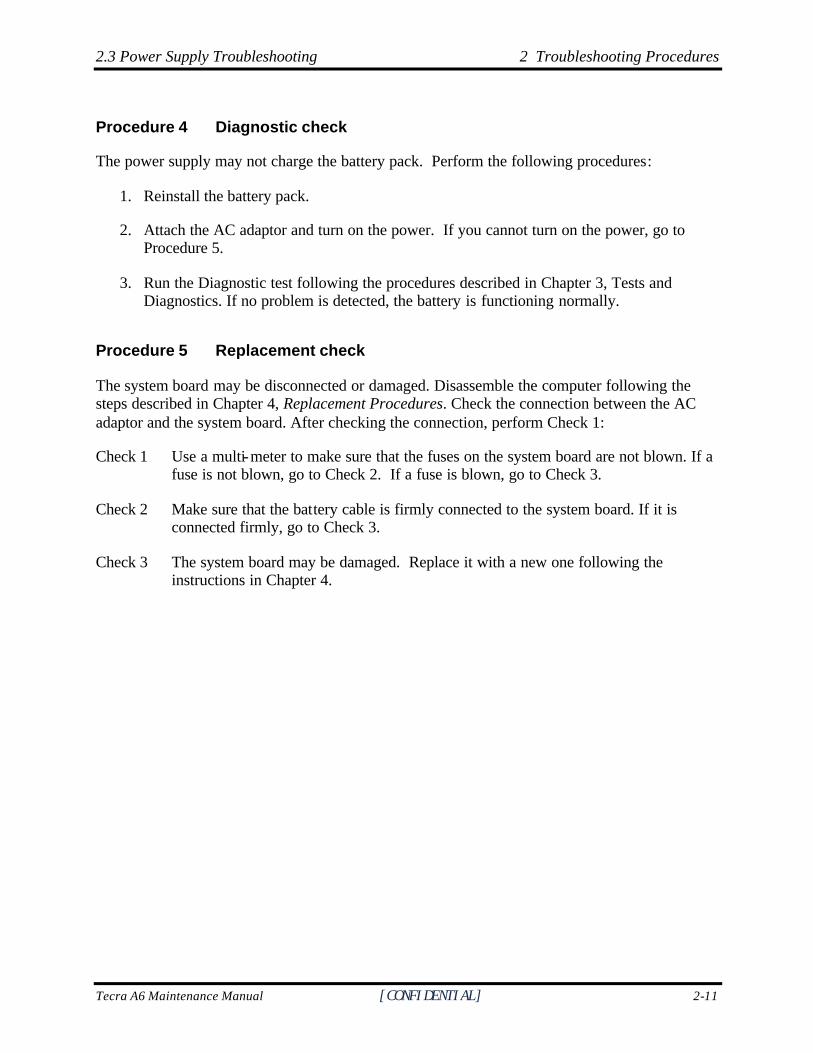
Procedure 4 Diagnostic check
The power supply may not charge the battery pack. Perform the following procedures:
1. Reinstall the battery pack.
2. Attach the AC adaptor and turn on the power. If you cannot turn on the power, go to Procedure 5.
3. Run the Diagnostic test following the procedures described in Chapter 3, Tests and Diagnostics. If no problem is detected, the battery is functioning normally.
Procedure 5 Replacement check
The system board may be disconnected or damaged. Disassemble the computer following the steps described in Chapter 4, Replacement Procedures. Check the connection between the AC adaptor and the system board. After checking the connection, perform Check 1:
Check 1 Use a multi-meter to make sure that the fuses on the system board are not blown. If a fuse is not blown, go to Check 2. If a fuse is blown, go to Check 3.
Check 2 Make sure that the battery cable is firmly connected to the system board. If it is connected firmly, go to Check 3.
Check 3 The system board may be damaged. Replace it with a new one following the instructions in Chapter 4.
2 Troubleshooting Procedures 2.4 Display Troubleshooting
2-12 [CONFIDENTIAL] Tecra A6 Maintenance Manual
2.4 Display Troubleshooting
P e r f o r m e x t e r n a l d i s p l a y c h e c k( P r o c e d u r e 1 )
S T A R T
D o e s t h e e x t e r n a ld i sp l ay func t i on ok?
P e r f o r m d i a g n o s t i c c h e c k( P r o c e d u r e 2 )
N o
W a s a d i s p l a yp r o b l e m d e t e c t e d ?
P e r f o r m c o n n e c t o r a n dr e p l a c e m e n t c h e c k
( P r o c e d u r e 3 )
R e p l a c e s y s t e m b o a r d
E N D
Yes
Y e s
N o
Disp lay i s no tfau l ty . Cont inuet r o u b l e s h o o t i n g -
re fe r to F igure 2 .1
Figure 2-4 Display troubleshooting process
2.4 Display Troubleshooting 2 Troubleshooting Procedures
Tecra A6 Maintenance Manual [CONFIDENTIAL] 2-13
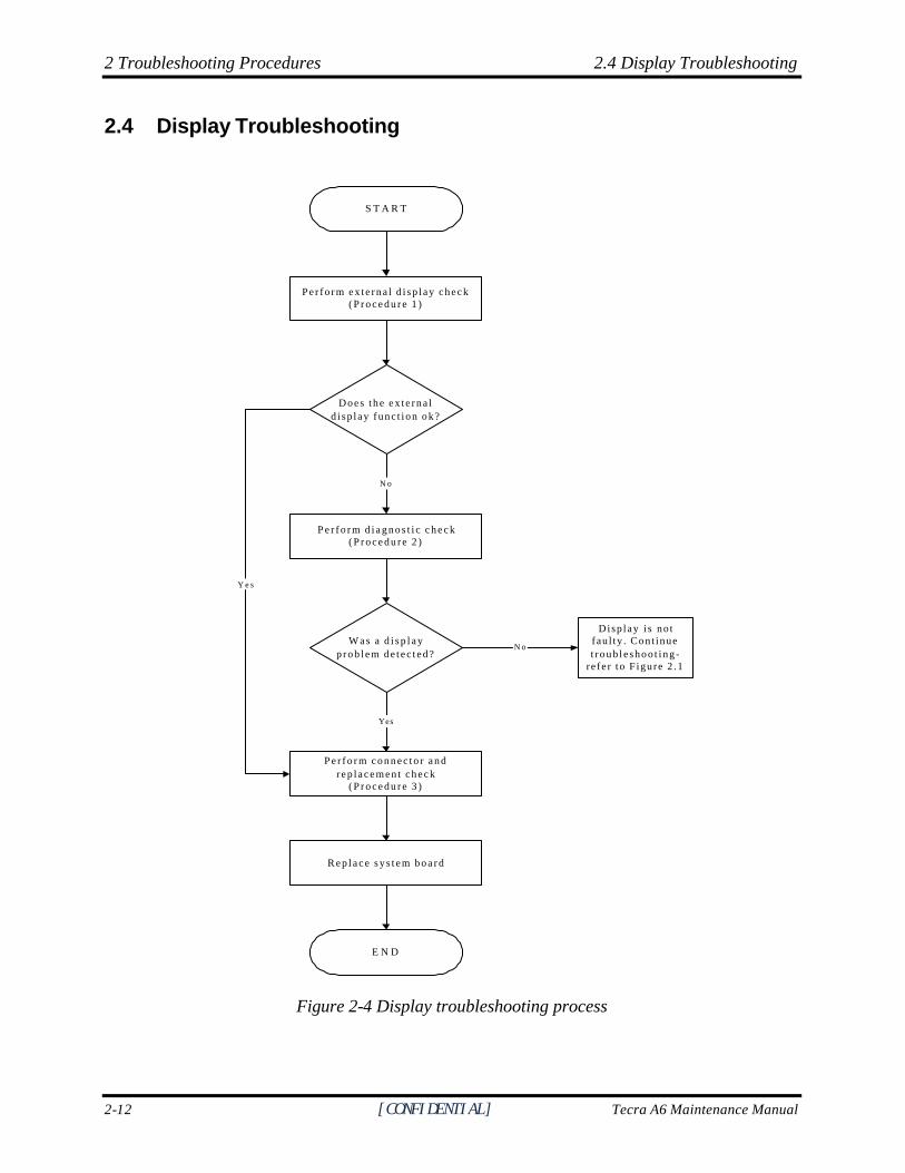
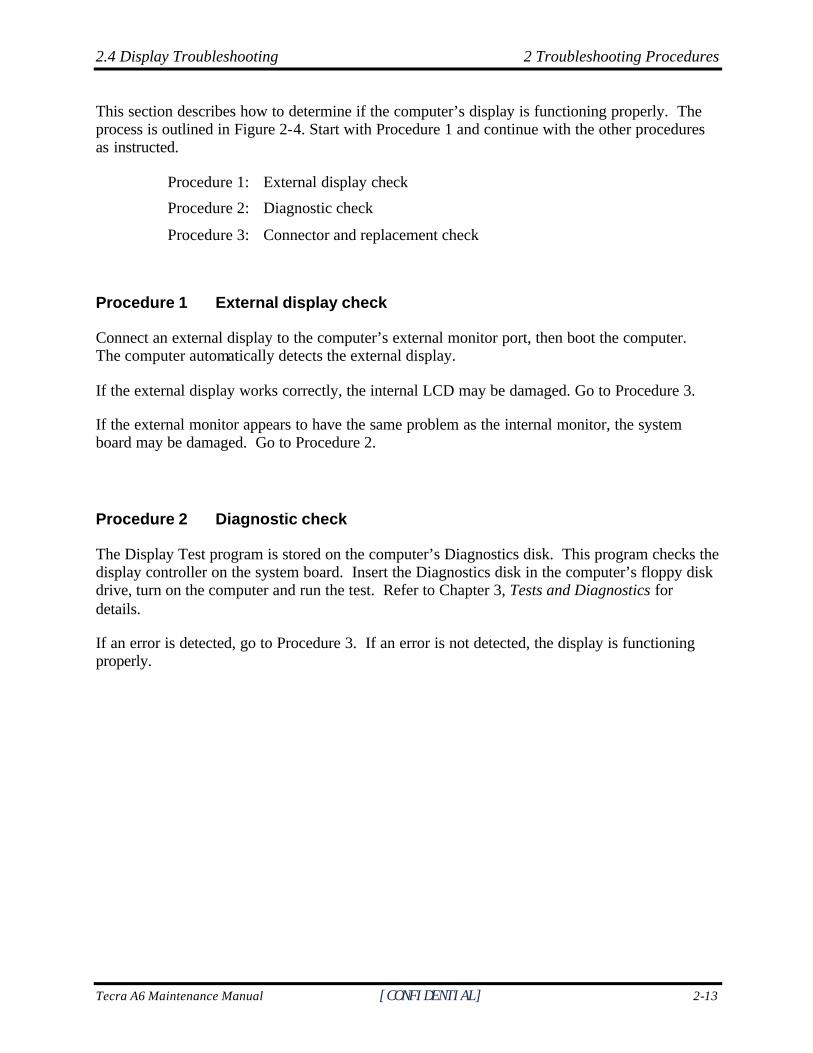
This section describes how to determine if the computer’s display is functioning properly. The process is outlined in Figure 2-4. Start with Procedure 1 and continue with the other procedures as instructed.
Procedure 1: External display check
Procedure 2: Diagnostic check
Procedure 3: Connector and replacement check
Procedure 1 External display check
Connect an external display to the computer’s external monitor port, then boot the computer. The computer automatically detects the external display.
If the external display works correctly, the internal LCD may be damaged. Go to Procedure 3.
If the external monitor appears to have the same problem as the internal monitor, the system board may be damaged. Go to Procedure 2.
Procedure 2 Diagnostic check
The Display Test program is stored on the computer’s Diagnostics disk. This program checks the display controller on the system board. Insert the Diagnostics disk in the computer’s floppy disk drive, turn on the computer and run the test. Refer to Chapter 3, Tests and Diagnostics for details.
If an error is detected, go to Procedure 3. If an error is not detected, the display is functioning properly.
2 Troubleshooting Procedures 2.4 Display Troubleshooting
2-14 [CONFIDENTIAL] Tecra A6 Maintenance Manual
Procedure 3 Connector and replacement check
The FL inverter board, LCD module, and system board are connected to the display circuits. Any of these components may be damaged. Refer to Chapter 4, Replacement Procedures, for instructions on how to disassemble the computer and then perform the following checks:
Check 1 Make sure the DDR RAM module is seated properly. Test display again. If the problem still exits, replace the DDR RAM module. If the problem still exists, perform Check 2.
Check 2 Replace the FL inverter board with a new one and test display again. If the problem still exists, perform Check 3.
Check 3 Replace the LCD module with a new one and test display again. If the problem still exists, perform Check 4.
Check 4 Replace the LCD/FL cable with a new one and test display again. If the problem still exists, perform Check 5.
Check 5 Replace the CPU with another of the same specifications. If the problem still exists, perform Check 6.
Check 6 The system board may be damaged. Replace it with a new one.
2.5 Keyboard Troubleshooting 2 Troubleshooting Procedures
Tecra A6 Maintenance Manual [CONFIDENTIAL] 2-15
2.5 Keyboard Troubleshooting
P e r f o r m e x t e r n a l k e y b o a r d c h e c k( P r o c e d u r e 1 )
S T A R T
D o e s t h e e x t e r n a lkeyboa rd func t i on ok?
P e r f o r m d i a g n o s t i c c h e c k( P r o c e d u r e 2 )
W a s a k e y b o a r dp r o b l e m d e t e c t e d ?
P e r f o r m c o n n e c t o r a n dr e p l a c e m e n t c h e c k
( P r o c e d u r e 3 )
R e p l a c e s y s t e m b o a r d
E N D
Yes
N o
K e y b o a r d i s n o tfau l ty . Cont inuet r o u b l e s h o o t i n g -
re fe r to F igure 2 .1
N o
Yes
Figure 2-5 Keyboard troubleshooting process
2 Troubleshooting Procedures 2.5 Keyboard Troubleshooting
2-16 [CONFIDENTIAL] Tecra A6 Maintenance Manual
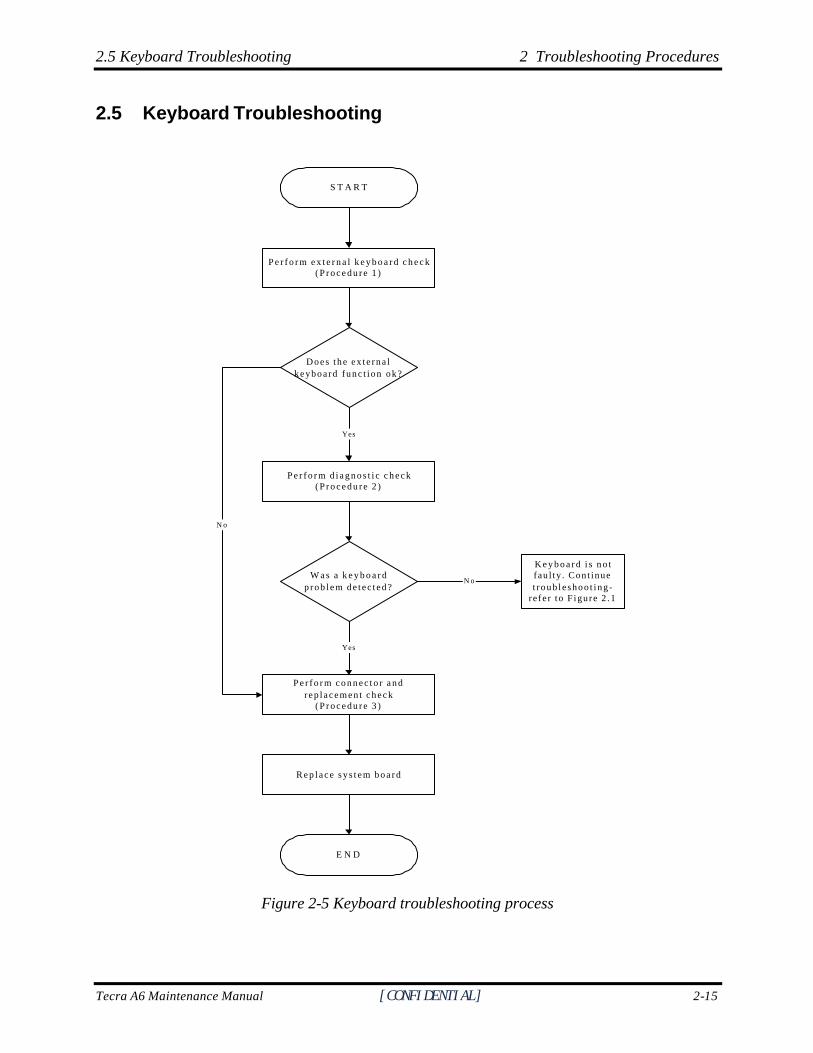
To determine if the computer’s keyboard is functioning properly, perform the following procedures. Figure 2-5 outlines the process. Start with Procedure 1 and continue with the other procedures as instructed.
Procedure 1: External keyboard check
Procedure 2: Diagnostic check
Procedure 3: Connector and replacement check
Procedure 1 External keyboard check
Connect a USB keyboard to one of the computer’s USB ports, then boot the computer. The computer automatically detects the external keyboard.
If the external keyboard works correctly, the internal keyboard or its connections may be faulty. Go to Procedure 2.
If the external keyboard appears to have the same problem as the internal keyboard, the system board may be damaged. Replace it with a new one following the instructions in Chapter 4.
Procedure 2 Diagnostic check
Run the Diagnostic Program, which will automatically execute the Keyboard Test. Refer to Chapter 3, Tests and Diagnostics for more information on how to run the program.
If an error is located, go to Procedure 3. If an error does not occur, the keyboard is functioning properly.
Procedure 3 Connector and replacement check
The keyboard and/or system board may be disconnected or damaged. Disassemble the computer following the steps described in Chapter 4, Replacement Procedures and perform the following checks.
Check 1 Make sure the keyboard cable is firmly connected to the system board.
If the connection is loose, reconnect firmly and repeat Procedure 2. If there is still an error, go to Check 2.
Check 2 The keyboard may be damaged. Replace it with a new one following the instructions in Chapter 4.
If the problem still exists, perform Check 3.
Check 3 The system board may be damaged. Replace it with a new one following the instructions in Chapter 4.
2.6 External USB Devices Troubleshooting 2 Troubleshooting Procedures
Tecra A6 Maintenance Manual [CONFIDENTIAL] 2-17
2.6 External USB Devices Troubleshooting
R e p l a c e s y s t e m b o a r d( P r o c e d u r e 2 )
E N D
O r i g i n a l U S Bdevice i s fau l ty
P e r f o r m e x t e r n a l d e v i c e a n dc o n n e c t i o n c h e c k
( P r o c e d u r e 1 )
S T A R T
D o e s t h e d e v i c e f u n c t i o nw h e n c o n n e c t e d t o ad i f f e r e n t U S B p o r t ?
D o e s a n a l t e r n a t i v e U S Bdev ice func t ion co r r ec t ly?
N o
Y e s
N o
C h e c k U S B p o r tconnec t i on
Y e s
Figure 2-6 External USB device troubleshooting process
2.6 External USB Devices Troubleshooting 2 Troubleshooting Procedures
2-18 [CONFIDENTIAL] Tecra A6 Maintenance Manual
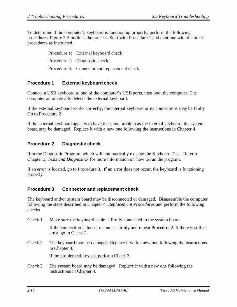
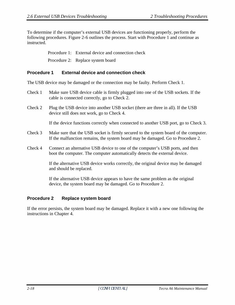
To determine if the computer’s external USB devices are functioning properly, perform the following procedures. Figure 2-6 outlines the process. Start with Procedure 1 and continue as instructed.
Procedure 1: External device and connection check
Procedure 2: Replace system board
Procedure 1 External device and connection check
The USB device may be damaged or the connection may be faulty. Perform Check 1.
Check 1 Make sure USB device cable is firmly plugged into one of the USB sockets. If the cable is connected correctly, go to Check 2.
Check 2 Plug the USB device into another USB socket (there are three in all). If the USB device still does not work, go to Check 4.
If the device functions correctly when connected to another USB port, go to Check 3.
Check 3 Make sure that the USB socket is firmly secured to the system board of the computer. If the malfunction remains, the system board may be damaged. Go to Procedure 2.
Check 4 Connect an alternative USB device to one of the computer’s USB ports, and then boot the computer. The computer automatically detects the external device.
If the alternative USB device works correctly, the original device may be damaged and should be replaced.
If the alternative USB device appears to have the same problem as the original device, the system board may be damaged. Go to Procedure 2.
Procedure 2 Replace system board
If the error persists, the system board may be damaged. Replace it with a new one following the instructions in Chapter 4.
2.7 TV-Out Failure Troubleshooting 2 Troubleshooting Procedures
Tecra A6 Maintenance Manual [CONFIDENTIAL] 2-19
2.7 TV-Out Failure Troubleshooting
P e r f o r m T V c o n n e c t i o n c h e c k( P r o c e d u r e 1 )
S T A R T
D o e s r e p l a c e m e n t T V c a b l efunc t ion p roper ly?
P e r f o r m T V s e t c h e c k( P r o c e d u r e 2 )
R e p l a c e s y s t e m b o a r d
E N D
N o R e p l a c e T V c a b l e
N o
TV func t ion ing ok?
Yes
U s e d i f f e r e n t T Vs e t
No
Figure 2-7 TV-out troubleshooting process
2 Troubleshooting Procedures 2.7 TV-Out Failure Troubleshooting
2-20 [CONFIDENTIAL] Tecra A6 Maintenance Manual
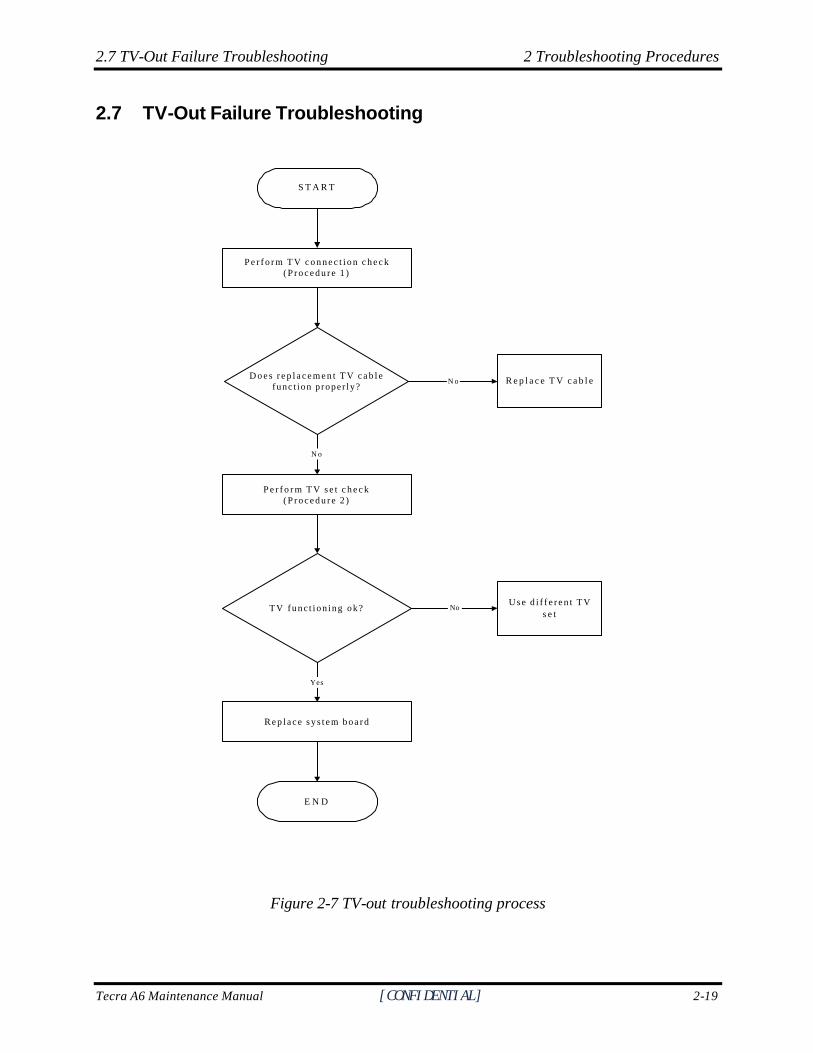
To determine if the computer’s TV-out port is functioning properly, perform the following procedures. Figure 2-7 outlines the process. Start with Procedure 1 and continue as instructed.
Procedure 1: TV connection check
Procedure 2: TV set check
Procedure 1 TV connection check
The TV cable may be damaged or the connections may be loose. Perform Check 1:
Check 1 Make sure TV cable is firmly plugged into both the TV set and the TV-out port of the computer. If the cable is connected correctly, go to Check 2.
Check 2 Make sure the TV-out port is firmly secured to the system board of the computer. If the malfunction remains, go to Check 3.
Check 3 The TV cable may be damaged. Replace with a good cable. If the malfunction remains, go to Procedure 2.
Procedure 2 TV set check
The TV set may be faulty. Perform Check 1:
Check 1 Try using the set for television reception. If it does not work, the set may be damaged. If the set does work, perform Check 2.
Check 2 Try connecting a different television to the computer. If the replacement television works, the original set may be damaged. If the replacement set does not work the system board may be damaged. Replace it with a new one following the instructions in Chapter 4.
2.8 Touch Pad Troubleshooting 2 Troubleshooting Procedures
Tecra A6 Maintenance Manual [CONFIDENTIAL] 2-21
2.8 TouchPad Troubleshooting
START
END
TouchPad connectioncheck (Procedure 1)
TouchPad replacementcheck (Procedure 2)
Replace system board
Figure 2-8 TouchPad troubleshooting process
2 Troubleshooting Procedures 2.8 TouchPad Troubleshooting
2-22 [CONFIDENTIAL] Tecra A6 Maintenance Manual
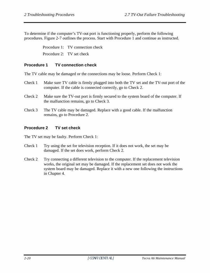
To determine if the computer’s built- in TouchPad is functioning properly, perform the following procedures. Figure 2-8 outlines the process. Start with Procedure 1 and continue as instructed.
Procedure 1: TouchPad connection check
Procedure 2: TouchPad replacement check
Procedure 1 TouchPad connection check
The TouchPad is connected via the TouchPad FPC to the system board. Make sure the TouchPad FPC cable is firmly connected to the TouchPad and system board. Refer to Chapter 4, Replacement Procedures, for instructions on how to disassemble the computer and then perform the following checks.
If any of the connections are loose, reconnect firmly. If any of the connections is damaged, or there is still an error, go to Procedure 2.
Procedure 2 TouchPad replacement check
The TouchPad unit or FPC may be defective or damaged. Replace each with a new one following the steps in Chapter 4. If the FDD is still not functioning properly, replace the system board with a new one following the steps in Chapter 4.
2.9 Speaker Troubleshooting 2 Troubleshooting Procedures
Tecra A6 Maintenance Manual [CONFIDENTIAL] 2-23
2.9 Speaker Troubleshooting
START
Do all sources havesame problem?
END
Perform earphone test(Procedure 2)
Do earphonesfunction correctly?
Perform connection check(Procedure 3)
Perform replacementcheck
(Procedure 4)
Perform audio source test(Procedure 1)
No
Yes
Yes
Replace system board
Speakers are notfaulty. Continue
troubleshooting -see Figure 2-1
No
Figure 2-9 Speaker troubleshooting process
2 Troubleshooting Procedures 2.9 Speaker Troubleshooting
2-24 [CONFIDENTIAL] Tecra A6 Maintenance Manual
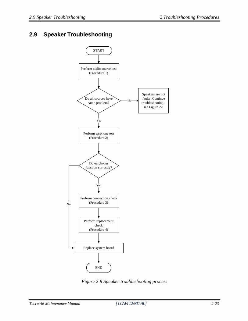
To determine if the computer’s built- in speakers are functioning properly, perform the following procedures. Figure 2-9 outlines the process. First adjust the speaker volume to an appropriate level. Start with Procedure 1 and continue as instructed.
Procedure 1: Audio source test
Procedure 2: Earphone test
Procedure 3: Connection check
Procedure 4: Replacement check
Procedure 1 Audio source test
Try different audio sources (e.g. an audio CD and digital music file) to determine whether the fault is in the speaker system or not. If not all sources have sound problem, the problem is in the source devices. If all have the same problem, continue with Procedure 2.
Procedure 2 Earphone test
Connect a set if earphones or external speakers. If these function correctly, go to Procedure 3. If they do not function correctly, the system board may be defective or damaged. Replace it with a new one.
Procedure 3 Connection check
Disassemble the computer following the steps described in Chapter 4, Replacement Procedures and make sure the speaker cable is firmly connected to the audio board. If the stereo speakers are still not functioning properly, go to Procedure 4.
Procedure 4 Replacement check
If the stereo speakers don't sound properly, the stereo speakers may be defective or damaged. Replace them with new ones. If the stereo speakers still do not work properly, try replacing in turn the audio board and system board.
2.10 Optical Drive Troubleshooting 2 Troubleshooting Procedures
Tecra A6 Maintenance Manual [CONFIDENTIAL] 2-27
2.10 Optical Drive Troubleshooting
START
Audio CD functions ok?
END
Perform software check(Procedure 3)
Perform diagnostic test(Procedure 4)
Perform connection andreplacement check
(Procedure 5)
Perform audio CD check(Procedure 1)
Perform drive-cleaning check(Procedure 2)
No
Yes
Replace system board
Figure 2-10 Optical drive troubleshooting process
2 Troubleshooting Procedures 2.10 Optical Drive Troubleshooting
2-28 [CONFIDENTIAL] Tecra A6 Maintenance Manual
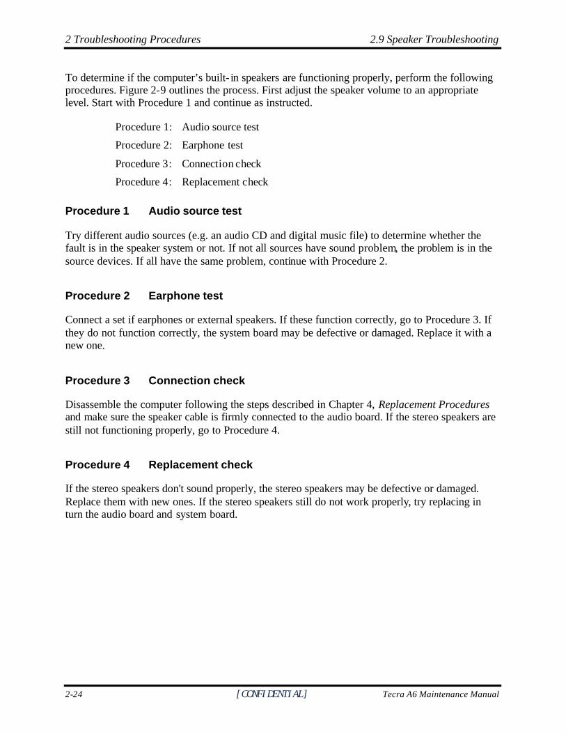
This section describes how to determine if the computer’s internal optical drive is functioning properly. The Satellite P10 module bays can accommodate the following optical drives:
? DVD-R/RW device ? DVD-ROM device ? DVD Multi-drive device ? COMBO device
Figure 2-11 outlines the process. Perform the steps below starting with Procedure 1 and continue with the other procedures as required.
Procedure 1: Audio CD test
Procedure 2: Drive cleaning check
Procedure 3: Software check
Procedure 4: Diagnostic test
Procedure 5: Connection and replacement check
Procedure 1 Audio CD check
First, insert an audio CD into the CD/DVD drive. If it works, the problem is not with the drive. Go to Procedure 3. If the audio CD does not work, go to Procedure 2. If the CD/DVD LED on the front panel does not light when the disc is played and the drive gives no response, go straight to Procedure 3.
Procedure 2 Drive cleaning check
Insert a CD/DVD drive-cleaning disk into the drive clean according to the drive-cleaning product instructions. If the problem persists, go to Procedure 3.
Procedure 3 Software check
Ensure that the appropriate driver has been installed on the computer for the CD/DVD drive.
Procedure 4 Diagnostic test
The audio test program stored in the Diagnostics Disk will test the drive’s ability to play an audio CD. See Chapter 3 for details. If any errors occur while executing the diagnostic program, go to Procedure 5.
2.10 Optical Drive Troubleshooting 2 Troubleshooting Procedures
Tecra A6 Maintenance Manual [CONFIDENTIAL] 2-29
Procedure 5 Connection check and replacement check
The optical drive connects to the system board. The drive may be disconnected, or the drive or system board may be damaged. Disassemble the computer following the steps described in Chapter 4, Replacement Procedures, and perform the following checks: Check 1 Make sure the drive is firmly connected to the system board. If the connection is
good and there is still an error, go to Check 2.
Check 2 The drive or drive cable may be defective or damaged. Replace each with a new one following the steps in Chapter 4, Replacement Procedures. If the drive is still not functioning properly, perform Check 3.
Check 3 The system board may be damaged. Replace it with new one following the instructions in Chapter 4, Replacement Procedures.
2 Troubleshooting Procedures 2.11 Modem Troubleshooting
2-30 [CONFIDENTIAL] Tecra A6 Maintenance Manual
2.11 Modem Troubleshooting
START
Computer unable todetect telephone signal?
END
Perform connection check(Procedure 2)
Perform replacementcheck
(Procedure 3)
Perform telephone lineconnection check
(Procedure 1)
Check / replacetelephone line and
connectionsYes
Replace system board
No
Figure 2-11 Modem troubleshooting process
2.11 Modem Troubleshooting 2 Troubleshooting Procedures
Tecra A6 Maintenance Manual [CONFIDENTIAL] 2-31
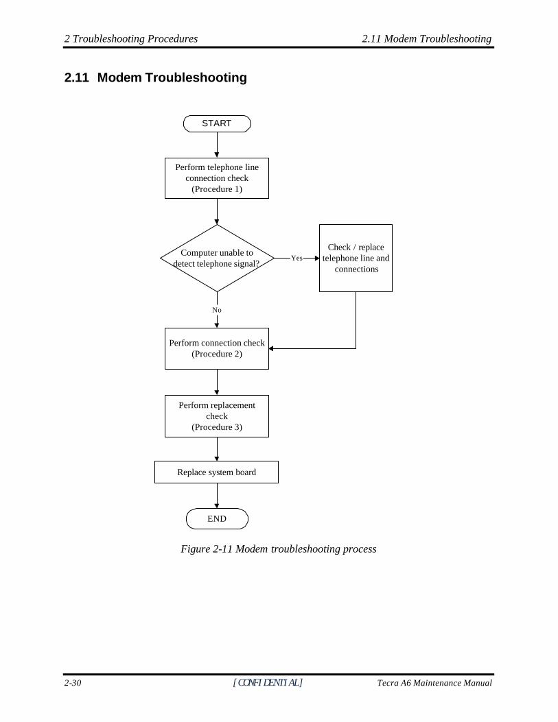
This section describes how to determine if the computer's modem is functioning properly. Figure 2-11 outlines the process. Perform the steps below starting with Procedure 1 and continuing with the other procedures as required.
Procedure 1: Telephone line connection check
Procedure 2: Modem card connection check
Procedure 3: Modem card replacement check
Procedure 1 Telephone line connection check
The telephone cable may be damaged or the connections may be loose. Attempt to connect the computer to a network through using the modem. If the modem does not function at all, go to Procedure 3. If the attempt fails because the computer detects no telephone signal, the fault may be in the telephone cable, the wall socket or the modem port. Perform Check 1: Check 1 Make sure telephone cable is firmly plugged into both the telephone wall socket and
the modem port of the computer. If the cable is connected correctly, go to Check 2.
Check 2 Make sure the modem port is firmly secured to the system board of the computer. If the malfunction remains, go to Check 3.
Check 3 The telephone cable may be damaged. Replace with a good cable. If the malfunction remains, go to Procedure 2.
Procedure 2 Modem card connection check
Disassemble the computer following the steps described in Chapter 4, Replacement Procedures and ensure that the modem card is well connected to the system board. If the problem persists, perform Procedure 3.
Procedure 3 Modem replacement check
The modem card or RJ-11 jack may be faulty. Try replacing them. If the problem persists, the system board may be defective or damaged. Replace the System Board with a new one following the steps in Chapter 4, Replacement Procedures.
2 Troubleshooting Procedures 2.12 PCMCIA Troubleshooting
2-32 [CONFIDENTIAL] Tecra A6 Maintenance Manual
2.12 PCMCIA Troubleshooting
START
Do errors occur duringSYCARD test?
Perform PCMCIA socketreplacement check
(Procedure 2)
Replace system board
END
PCMCIA unit isnot faulty.
Perform SYCARD test(Procedure 1)
No
Yes
Figure 2-12 PCMCIA troubleshooting process
2.12 PCMCIA Troubleshooting 2 Troubleshooting Procedures
Tecra A6 Maintenance Manual [CONFIDENTIAL] 2-33
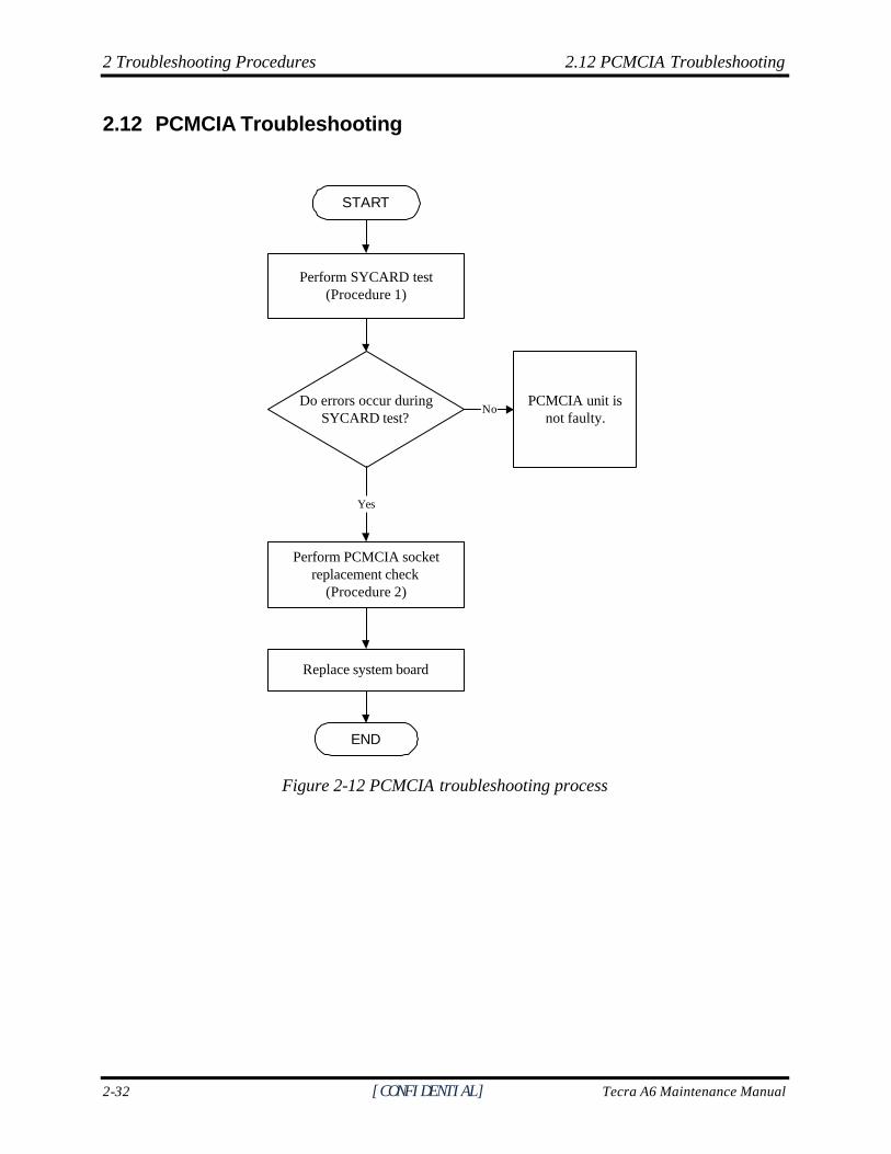
This section describes how to determine if the PCMCIA card player is functioning properly. The process is summarized in Figure 2-12. Perform the steps below starting with Procedure 1 and continuing with the other procedures as required.
Procedure 1: Sycard test
Procedure 2: PCMCIA socket replacement check
Procedure 1 SYCARD test
The SYCARD test card contains a PCMCIA test program. Ensure the card in fully inserted into the socket before running the program. If an error occurs during the SYCARD test, perform Procedure 2. If no error occurs, it is likely that the original PC card was faulty.
Procedure 2 PCMCIA socket replacement check
The PCMCIA socket may be damaged or defective, for instance the socket pins can be bent. Disassemble the computer following the steps described in Chapter 4, Replacement Procedures and replace the socket. If the problem persists, the system board may be defective or damaged. Replace the system board with a new one following the steps in Chapter 4.
2 Troubleshooting Procedures 2.13 IEEE 1394 Troubleshooting
2-34 [CONFIDENTIAL] Tecra A6 Maintenance Manual
2.13 IEEE 1394 Troubleshooting
START
Perform IEEE 1394 device check(Procedure 1)
Is IEEE 1394 transmission ok?
Perform diagnostic check(Procedure 2)
Was an IEEE 1394 problem detected?
Perform connection and replacement check(Procedure 3)
Replace system board
END
Yes
Yes
IEEE 1394 port andtransmission are not
faulty. Continuetroubleshooting - refer
to Figure 2.1
NoNo
Figure 2-13 IEEE 1394 troubleshooting process
2.13 IEEE 1394 Troubleshooting 2 Troubleshooting Procedures
Tecra A6 Maintenance Manual [CONFIDENTIAL] 2-35
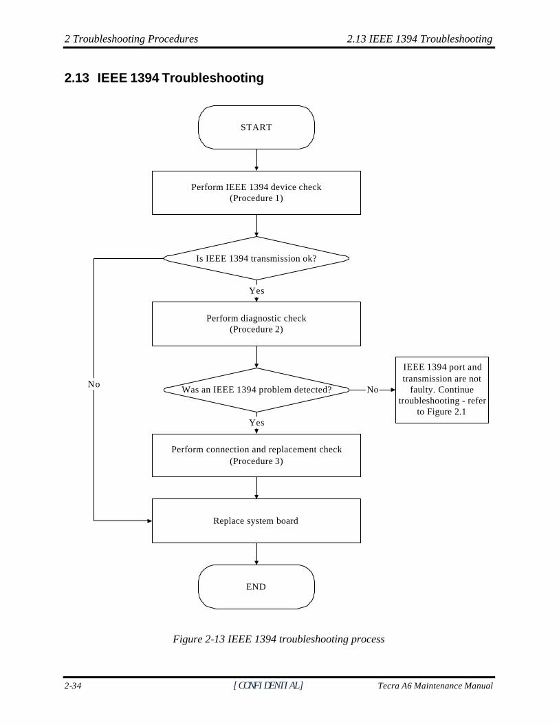
To determine if the computer’s IEEE 1394 system is functioning properly, perform the following procedures. Figure 2-13 outlines the process. Start with Procedure 1 and continue with the other procedures as instructed.
Procedure 1: IEEE 1394 device check
Procedure 2: Diagnostic check
Procedure 3: Connection and replacement check
Procedure 1 IEEE 1394 device check
Connect an IEEE 1394 device to the computer’s IEEE 1394 port, then boot the computer for Windows XP. The computer should automatically detect the 1394 device. Check whether the device can transmit data to the computer. If the device is able to communicate with the computer, the problem may be intermittent or connections may be faulty. Go to Procedure 2. If communication is impaired, there may be a faulty connection. Go to Procedure 3.
Procedure 2 Diagnostic check
Run the Diagnostic Program, which will automatically execute the IEEE 1394 port test for transmission. Refer to Chapter 3, Tests and Diagnostics for more information on how to run the program. If an error is located, go to Procedure 3. If an error does not occur, the 1394 port is functioning properly.
Procedure 3 Connection and replacement check
The transmission cable may be damaged or the connections may be loose. Perform Check 1:
Check 1 Make sure the transmission cable is firmly plugged into both the IEEE 1394-compatible device and the IEEE 1394 port of the computer. If the cable is connected correctly, go to Check 2.
Check 2 Make sure the IEEE 1394 port is firmly secured to the system board of the computer. If the malfunction persists, go to Check 3.
Check 3 The transmission cable may be damaged. Replace with a good cable. If the malfunction persists, go to Check 4
Check 4 The system board may be damaged. Replace it with a new one following the instructions in Chapter 4.
2 Troubleshooting Procedures 2.14 Wireless LAN Troubleshooting
2-36 [CONFIDENTIAL] Tecra A6 Maintenance Manual
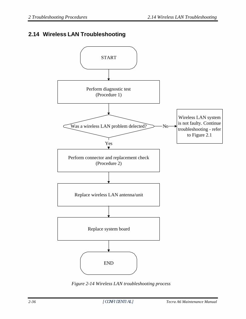
2.14 Wireless LAN Troubleshooting
START
Perform diagnostic test(Procedure 1)
Was a wireless LAN problem delected?
Perform connector and replacement check(Procedure 2)
Replace wireless LAN antenna/unit
Replace system board
END
Yes
Wireless LAN systemis not faulty. Continuetroubleshooting - refer
to Figure 2.1
No
Figure 2-14 Wireless LAN troubleshooting process
2.14 Wireless LAN Troubleshooting 2 Troubleshooting Procedures
Satellite M100 Series Maintenance Manual [CONFIDENTIAL] 2-37
The wireless LAN antenna wire, wireless LAN unit or system board may each be the source of a wireless LAN fault. Any of these components may be damaged. To determine if the computer’s wireless LAN system is functioning properly, perform the following procedures. Figure 2-15 outlines the process. Start with Procedure 1 and continue with the other procedures as instructed.
Procedure 1: Diagnostic test
Procedure 2: Connector and replacement check
Procedure 1 Diagnostic test
Run the Diagnostic Program, which will automatically execute the wireless LAN test. Refer to Chapter 3, Tests and Diagnostics for more information on the program. If an error is located, go to Procedure 2. If an error is not located, the wireless LAN system is functioning properly.
Procedure 2 Connector and replacement check
The wireless LAN antenna, wireless LAN unit or system board may be disconnected or damaged. Disassemble the computer following the steps described in Chapter 4, Replacement Procedures, and perform the following checks. Check 1 Make sure that the wireless LAN antenna is firmly connected to the wireless LAN
unit (refer to Chapter 4 for instructions) and that the wireless LAN unit is securely slotted into the system board. If the problem persists, go to Check 2.
Check 2 Check that the wireless communication switch is turned to “On”, then make sure that the wireless communication LED on the front panel is lit. If the LED is lit but the wireless LAN function is still faulty, the antenna may be damaged. Replace with a new antenna following the steps in Chapter 4, Replacement Procedures. If the problem persists, or if the wireless LAN LED is not lit when the wireless communication switch is turned to “On”, go to Check 3.
Check 3 The wireless LAN unit may be damaged. Replace it with a new one following the instructions in Chapter 4. If the problem still exists, perform Check 4.
Check 4 The system board may be damaged. Replace it with a new one following the instructions in Chapter 4.

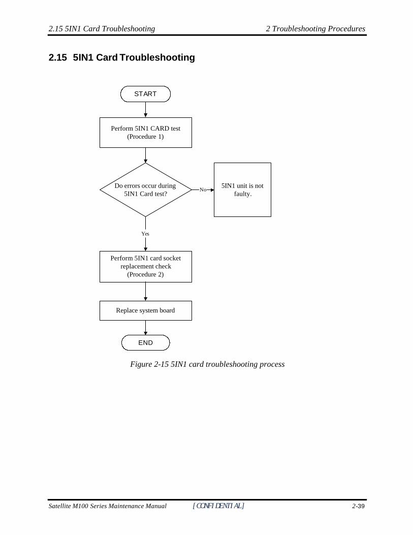
2.15 5IN1 Card Troubleshooting 2 Troubleshooting Procedures
Satellite M100 Series Maintenance Manual [CONFIDENTIAL] 2-39
2.15 5IN1 Card Troubleshooting
START
Do errors occur during5IN1 Card test?
Perform 5IN1 card socketreplacement check
(Procedure 2)
Replace system board
END
5IN1 unit is notfaulty.
Perform 5IN1 CARD test(Procedure 1)
No
Yes
Figure 2-15 5IN1 card troubleshooting process
2 Troubleshooting Procedures 2.16 Bluetooth Troubleshooting
2-40 [CONFIDENTIAL] Tecra A6 Maintenance Manual
This section describes how to determine if the 5IN1 card player is functioning properly. The process is summarized in Figure 2-15. Perform the steps below starting with Procedure 1 and continuing with the other procedures as required.
Procedure 1: 5IN1 (SD/MMC/MS/MS Pro/XD) card test
Procedure 2: 5IN1 socket replacement check
Procedure 1 5IN1 card test
The 5IN1 test card contains a 5IN1 test program. Ensure the card in fully inserted into the socket before running the program. If an error occurs during the 5IN1 card test, perform Procedure 2. If no error occurs, it is likely that the original 5IN1 card was faulty.
Procedure 2 5IN1 card socket replacement check
The 5IN1 card socket may be damaged or defective, for instance the socket pins can be bent. Disassemble the computer following the steps described in Chapter 4, Replacement Procedures and replace the socket. If the problem persists, the system board may be defective or damaged. Replace the system board with a new one following the steps in Chapter 4.
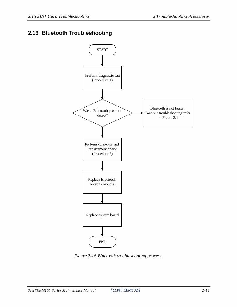
2.15 5IN1 Card Troubleshooting 2 Troubleshooting Procedures
Satellite M100 Series Maintenance Manual [CONFIDENTIAL] 2-41
2.16 Bluetooth Troubleshooting
START
Preform diagnostic test(Procedure 1)
Was a Bluetooth problem detect?
Bluetooth is not faulty. Continue troubleshooting-refer
to Figure 2.1
Replace system board
Perform connector and replacement check
(Procedure 2)
Replace Bluetooth antenna moudle.
END
Figure 2-16 Bluetooth troubleshooting process
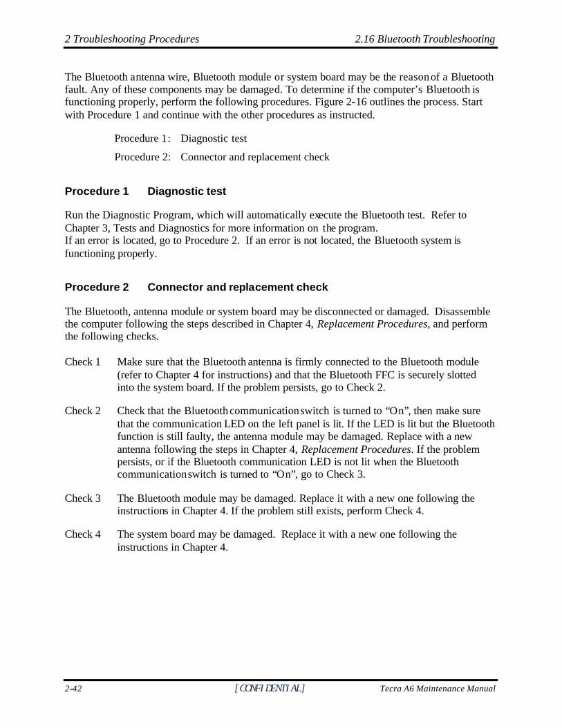
2 Troubleshooting Procedures 2.16 Bluetooth Troubleshooting
2-42 [CONFIDENTIAL] Tecra A6 Maintenance Manual
The Bluetooth antenna wire, Bluetooth module or system board may be the reason of a Bluetooth fault. Any of these components may be damaged. To determine if the computer’s Bluetooth is functioning properly, perform the following procedures. Figure 2-16 outlines the process. Start with Procedure 1 and continue with the other procedures as instructed.
Procedure 1: Diagnostic test
Procedure 2: Connector and replacement check
Procedure 1 Diagnostic test
Run the Diagnostic Program, which will automatically execute the Bluetooth test. Refer to Chapter 3, Tests and Diagnostics for more information on the program. If an error is located, go to Procedure 2. If an error is not located, the Bluetooth system is functioning properly.
Procedure 2 Connector and replacement check
The Bluetooth, antenna module or system board may be disconnected or damaged. Disassemble the computer following the steps described in Chapter 4, Replacement Procedures, and perform the following checks. Check 1 Make sure that the Bluetooth antenna is firmly connected to the Bluetooth module
(refer to Chapter 4 for instructions) and that the Bluetooth FFC is securely slotted into the system board. If the problem persists, go to Check 2.
Check 2 Check that the Bluetooth communication switch is turned to “On”, then make sure that the communication LED on the left panel is lit. If the LED is lit but the Bluetooth function is still faulty, the antenna module may be damaged. Replace with a new antenna following the steps in Chapter 4, Replacement Procedures. If the problem persists, or if the Bluetooth communication LED is not lit when the Bluetooth communication switch is turned to “On”, go to Check 3.
Check 3 The Bluetooth module may be damaged. Replace it with a new one following the instructions in Chapter 4. If the problem still exists, perform Check 4.
Check 4 The system board may be damaged. Replace it with a new one following the instructions in Chapter 4.
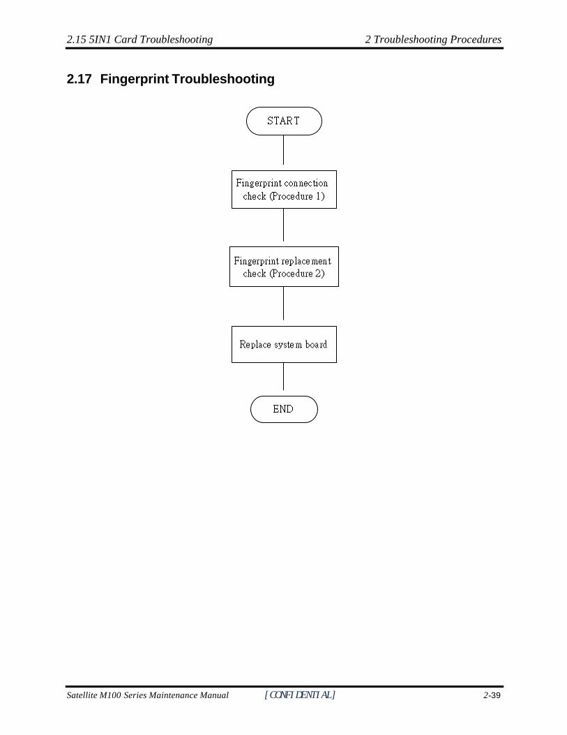
2.15 5IN1 Card Troubleshooting 2 Troubleshooting Procedures
Satellite M100 Series Maintenance Manual [CONFIDENTIAL] 2-39
2.17 Fingerprint Troubleshooting
Figure 2-17 Fingerprint troubleshooting process
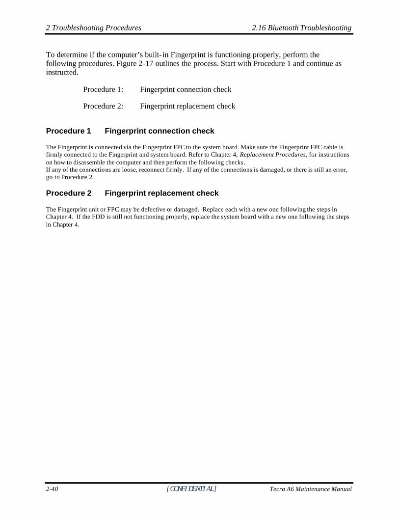
2 Troubleshooting Procedures 2.16 Bluetooth Troubleshooting
2-40 [CONFIDENTIAL] Tecra A6 Maintenance Manual
To determine if the computer’s built- in Fingerprint is functioning properly, perform the following procedures. Figure 2-17 outlines the process. Start with Procedure 1 and continue as instructed.
Procedure 1: Fingerprint connection check
Procedure 2: Fingerprint replacement check
Procedure 1 Fingerprint connection check
The Fingerprint is connected via the Fingerprint FPC to the system board. Make sure the Fingerprint FPC cable is firmly connected to the Fingerprint and system board. Refer to Chapter 4, Replacement Procedures, for instructions on how to disassemble the computer and then perform the following checks. If any of the connections are loose, reconnect firmly. If any of the connections is damaged, or there is still an error, go to Procedure 2.
Procedure 2 Fingerprint replacement check
The Fingerprint unit or FPC may be defective or damaged. Replace each with a new one following the steps in Chapter 4. If the FDD is still not functioning properly, replace the system board with a new one following the steps in Chapter 4.
2.15 5IN1 Card Troubleshooting 2 Troubleshooting Procedures
Satellite M100 Series Maintenance Manual [CONFIDENTIAL] 2-41
2.18 3D HDD Protection Troubleshooting
? ? ? ? ?
?¯??^¯` ?????´̂ ????????????¯^???¨¯??^'
? ?????ˆ????´?^¯?~¯^???` ????????
??~??????????` ??^?¯?
? ? ?
ˆ ? ??¨´???^´?´??~¯^~?¯??
???
? ^
Figure 2-18 3D HDD protection troubleshooting process
2 Troubleshooting Procedures 2.16 Bluetooth Troubleshooting
2-42 [CONFIDENTIAL] Tecra A6 Maintenance Manual
To determine if the computer’s built- in 3D HDD protection is functioning properly, perform the following procedures. Figure 2-18 outlines the process. Start with Procedure 1 and continue as instructed.
Procedure 1: Diagnostic test
Procedure 1 Diagnostic test
Run the Diagnostic Program, which will automatically execute the 3D sensor test. Refer to Chapter 3, Tests and Diagnostics for more information on the program. If an error is not located, the 3D HDD protection system is functioning properly.
3.1The Diagnostic Test 3. Tests and Diagnostics
Satellite M100/TECRA A6 Series Maintenance Manual 3-1
Chapter 3 Tests and Diagnostics 3
3-2 satellite M100/TECRA A6 Series Maintenance Manual
Contents
3.1 The Diagnostic Test .........................................................................................................3-3
3.2 Executing the Diagnostic Test..........................................................................................3-4
3.3 Display Configuration .....................................................................................................3-8
3.4 DMI Check Test ...............................................................................................................3-9
3.5 Speaker Audio Test ........................................................................................................3-10
3.6 Fan ON/OFF Test ...........................................................................................................3-11
3.7 Main Battery Charge Test ..............................................................................................3-12
3.8 FDD Test ........................................................................................................................3-13
3.9 ODD Test .......................................................................................................................3-14
3.10 Keyboard Test ................................................................................................................3-15
3.11 Mouse (Pad) Test ...........................................................................................................3-17
3.12 LCD Pixels Mode Test ...................................................................................................3-19
3.13 Magnetic switch Test .....................................................................................................3-20
3.14 HDD R/W Test ...............................................................................................................3-21
3.15 LAN Test ........................................................................................................................3-23
3.16 RTC Test ........................................................................................................................3-26
3.17 Speaker EQ Check&Rewrite..........................................................................................3-27
3.18 Read 1394 GUID…………...………………………………………………...……......3-29
3.19 6Button Test …………………………………………………………………………..3-30
3.20 Fingerprint DOS Test ……………………....…………………………………………3-31
3.21 3D G-Sensor DOS test ……………………………………………………………….3-33
3.22 Clear Fingerprint Registered…………………………………………………………...3-40
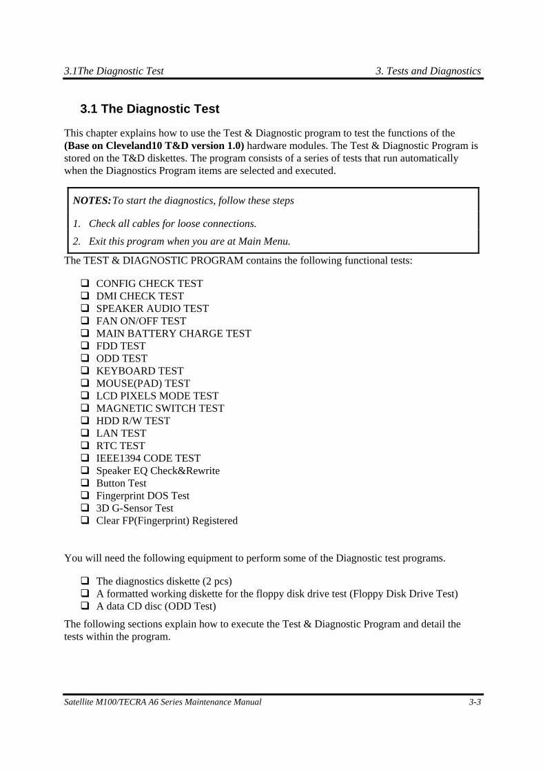
3.1The Diagnostic Test 3. Tests and Diagnostics
Satellite M100/TECRA A6 Series Maintenance Manual 3-3
3.1 The Diagnostic Test
This chapter explains how to use the Test & Diagnostic program to test the functions of the (Base on Cleveland10 T&D version 1.0) hardware modules. The Test & Diagnostic Program is stored on the T&D diskettes. The program consists of a series of tests that run automatically when the Diagnostics Program items are selected and executed.
NOTES: To start the diagnostics, follow these steps
1. Check all cables for loose connections.
2. Exit this program when you are at Main Menu.
The TEST & DIAGNOSTIC PROGRAM contains the following functional tests:
CONFIG CHECK TEST DMI CHECK TEST SPEAKER AUDIO TEST FAN ON/OFF TEST MAIN BATTERY CHARGE TEST FDD TEST ODD TEST KEYBOARD TEST MOUSE(PAD) TEST LCD PIXELS MODE TEST MAGNETIC SWITCH TEST HDD R/W TEST LAN TEST RTC TEST IEEE1394 CODE TEST Speaker EQ Check&Rewrite Button Test Fingerprint DOS Test 3D G-Sensor Test Clear FP(Fingerprint) Registered
You will need the following equipment to perform some of the Diagnostic test programs.
The diagnostics diskette (2 pcs) A formatted working diskette for the floppy disk drive test (Floppy Disk Drive Test) A data CD disc (ODD Test)
The following sections explain how to execute the Test & Diagnostic Program and detail the tests within the program.
3. Tests and Diagnostics 3.2 Executing the Diagnostic Test
3-4 satellite M100/TECRA A6 Series Maintenance Manual
3.2 Executing the Diagnostic Test
DOS is required to run the DIAGNOSTICS PROGRAM. To start the DIAGNOSTIC PROGRAM, follow these steps:
1. Insert the diagnostics diskette #1 in the floppy disk drive and turn on the computer. (The diagnostics diskette contains the DOS boot files.) And then follow the instructions to swap with the diagnostics diskette #2 for T&D program installed in RAM driver.
NOTE: To execute the CD test, make sure the CD is installed in the ODD drive.
The T&D Program can run by single test item when you press corresponsive English letter of test item, or run two or more test items what you like if you choose them by “Arrow cursors” and “Space Bar” – the wonderful thing is you can setup test loop by “Enter” button. And it also asks you if you like to copy test log file to diskette as reference at the end of test(s).
The test list is as the following:
A. CONFIG CHECK TEST B. DMI CHECK TEST C. RTC TEST D. LAN TEST E. SPEAKER AUDIO TEST F. FAN ON/OFF TEST G. MAIN BATTERY CHARGE TEST H. FDD TEST I. ODD TEST J. KEYBOARD TEST K. MOUSE (PAD) TEST L. LCD PIXELS MODE TEST M. MAGNETIC SWITCH TEST N. HDD R/W TEST O. IEEE1394 CODE TEST P. Speaker EQ Check&Rewrite Q. Button test R. Fingerprint DOS Test S. 3D G-sensor DOS Test T. Clear FP(Fingerprint) Registered
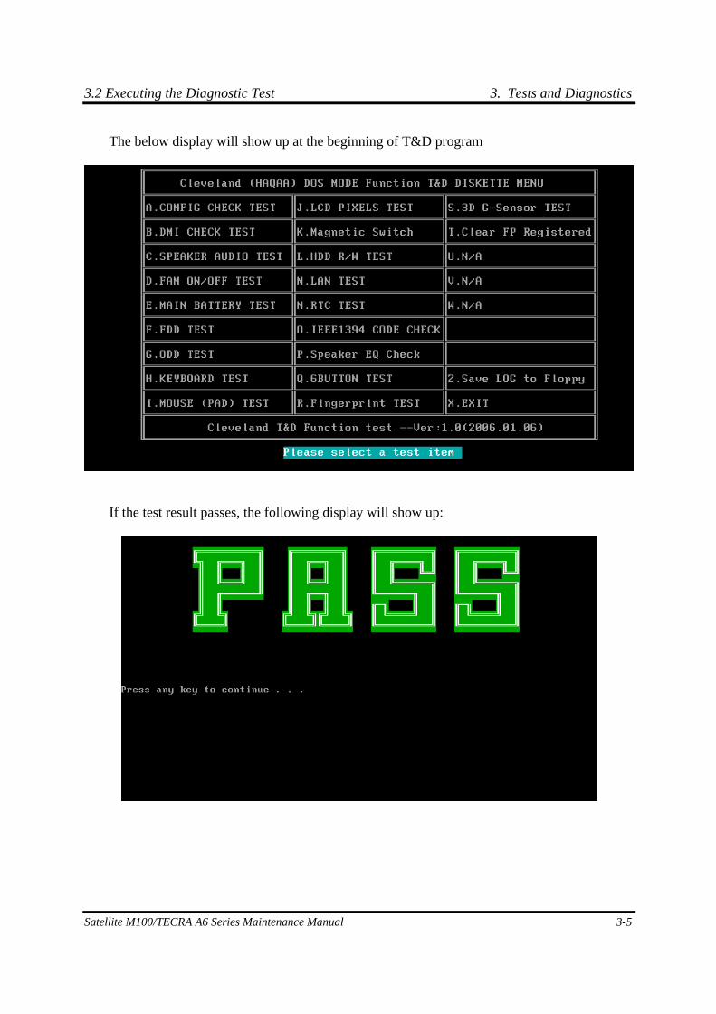
3.2 Executing the Diagnostic Test 3. Tests and Diagnostics
Satellite M100/TECRA A6 Series Maintenance Manual 3-5
The below display will show up at the beginning of T&D program
If the test result passes, the following display will show up:
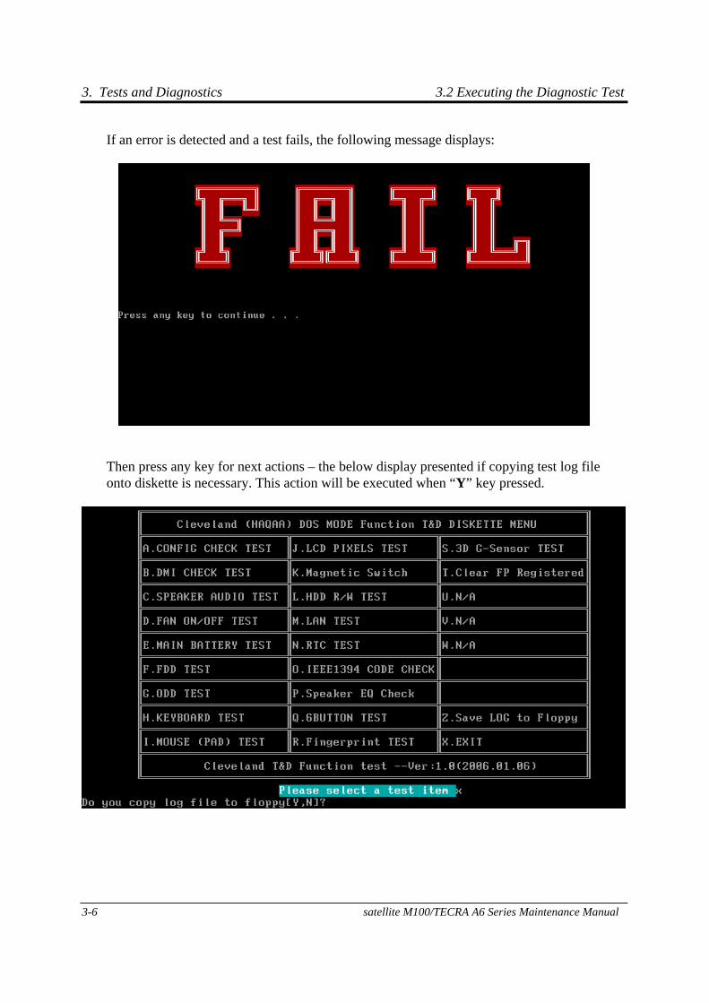
3. Tests and Diagnostics 3.2 Executing the Diagnostic Test
3-6 satellite M100/TECRA A6 Series Maintenance Manual
If an error is detected and a test fails, the following message displays:
Then press any key for next actions – the below display presented if copying test log file onto diskette is necessary. This action will be executed when “Y” key pressed.
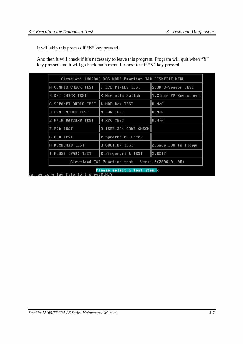
3.2 Executing the Diagnostic Test 3. Tests and Diagnostics
Satellite M100/TECRA A6 Series Maintenance Manual 3-7
It will skip this process if “N” key pressed.
And then it will check if it’s necessary to leave this program. Program will quit when “Y” key pressed and it will go back main menu for next test if “N” key pressed.
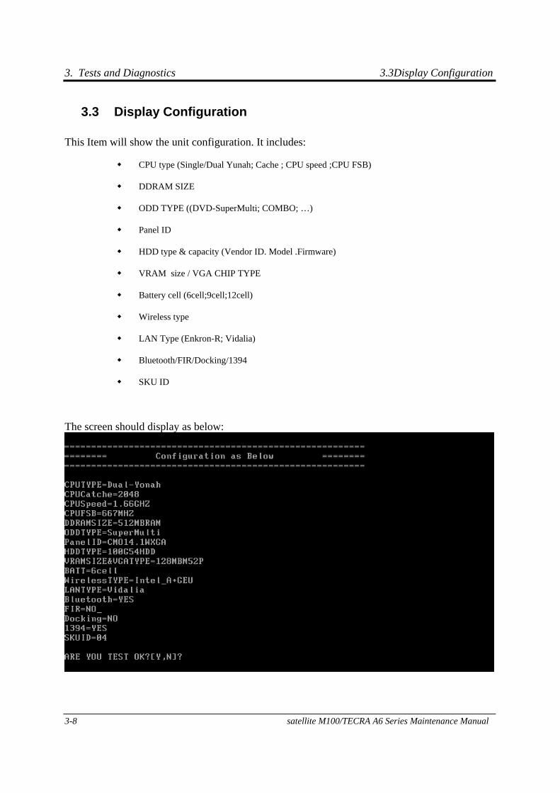
3. Tests and Diagnostics 3.3Display Configuration
3-8 satellite M100/TECRA A6 Series Maintenance Manual
3.3 Display Configuration
This Item will show the unit configuration. It includes:
CPU type (Single/Dual Yunah; Cache ; CPU speed ;CPU FSB)
DDRAM SIZE
ODD TYPE ((DVD-SuperMulti; COMBO; …)
Panel ID
HDD type & capacity (Vendor ID. Model .Firmware)
VRAM size / VGA CHIP TYPE
Battery cell (6cell;9cell;12cell)
Wireless type
LAN Type (Enkron-R; Vidalia)
Bluetooth/FIR/Docking/1394
SKU ID
The screen should display as below:
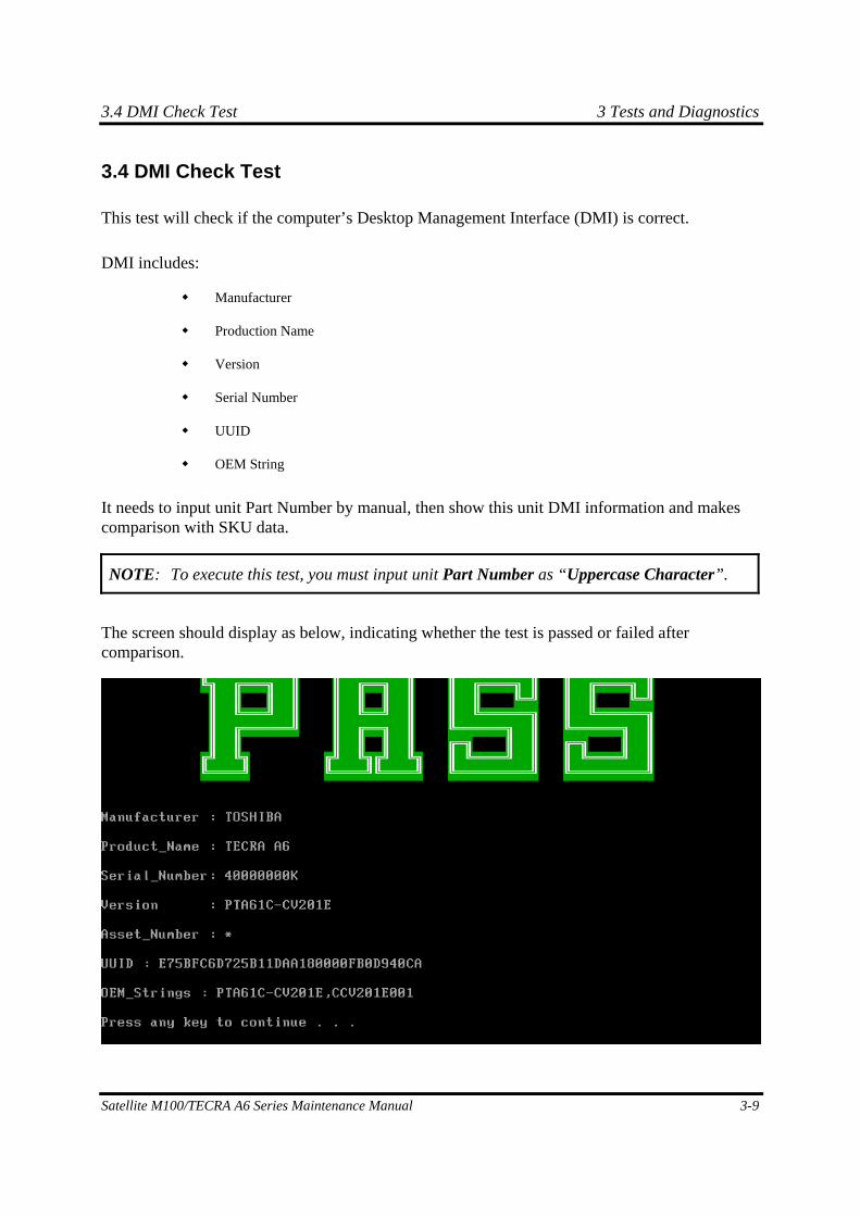
3.4 DMI Check Test 3 Tests and Diagnostics
Satellite M100/TECRA A6 Series Maintenance Manual 3-9
3.4 DMI Check Test
This test will check if the computer’s Desktop Management Interface (DMI) is correct.
DMI includes:
Manufacturer
Production Name
Version
Serial Number
UUID
OEM String
It needs to input unit Part Number by manual, then show this unit DMI information and makes comparison with SKU data.
NOTE: To execute this test, you must input unit Part Number as “Uppercase Character”.
The screen should display as below, indicating whether the test is passed or failed after comparison.
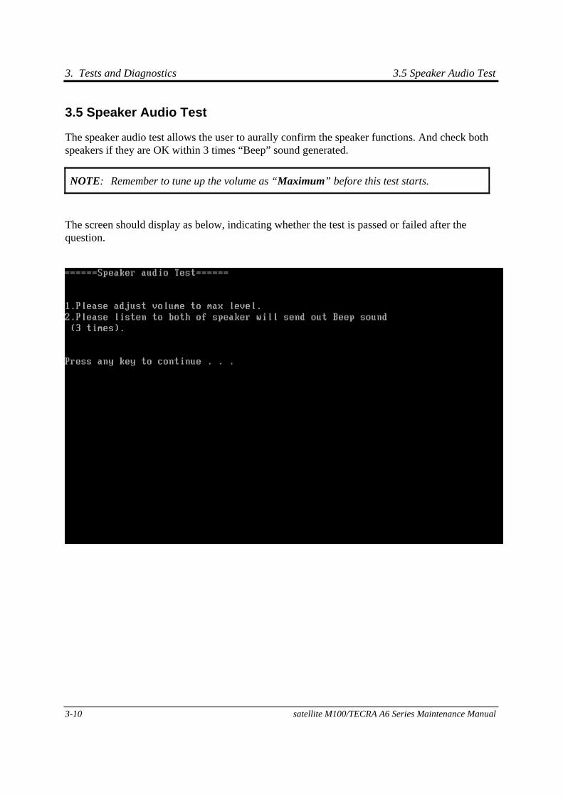
3. Tests and Diagnostics 3.5 Speaker Audio Test
3-10 satellite M100/TECRA A6 Series Maintenance Manual
3.5 Speaker Audio Test
The speaker audio test allows the user to aurally confirm the speaker functions. And check both speakers if they are OK within 3 times “Beep” sound generated.
NOTE: Remember to tune up the volume as “Maximum” before this test starts.
The screen should display as below, indicating whether the test is passed or failed after the question.
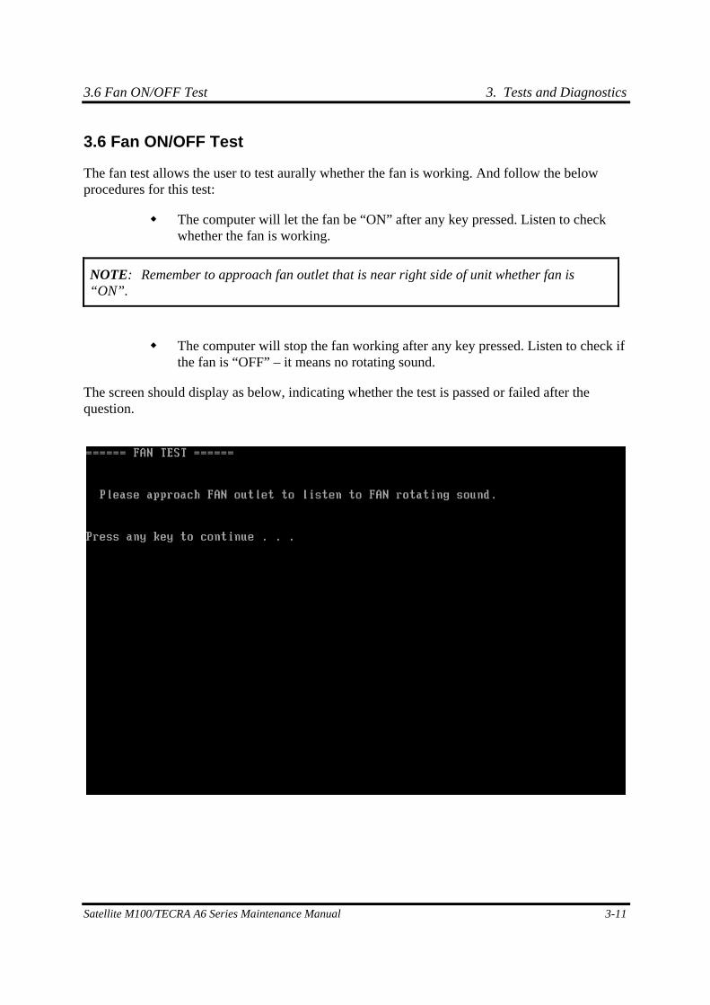
3.6 Fan ON/OFF Test 3. Tests and Diagnostics
Satellite M100/TECRA A6 Series Maintenance Manual 3-11
3.6 Fan ON/OFF Test
The fan test allows the user to test aurally whether the fan is working. And follow the below procedures for this test:
The computer will let the fan be “ON” after any key pressed. Listen to check whether the fan is working.
NOTE: Remember to approach fan outlet that is near right side of unit whether fan is “ON”.
The computer will stop the fan working after any key pressed. Listen to check if the fan is “OFF” – it means no rotating sound.
The screen should display as below, indicating whether the test is passed or failed after the question.
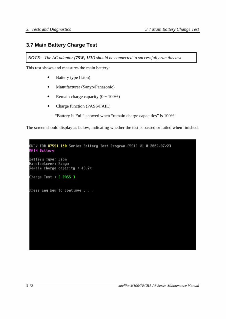
3. Tests and Diagnostics 3.7 Main Battery Change Test
3-12 satellite M100/TECRA A6 Series Maintenance Manual
3.7 Main Battery Charge Test
NOTE: The AC adaptor (75W, 15V) should be connected to successfully run this test.
This test shows and measures the main battery:
Battery type (Lion)
Manufacturer (Sanyo/Panasonic)
Remain charge capacity (0 ~ 100%)
Charge function (PASS/FAIL)
- “Battery Is Full” showed when “remain charge capacities” is 100%
The screen should display as below, indicating whether the test is passed or failed when finished.
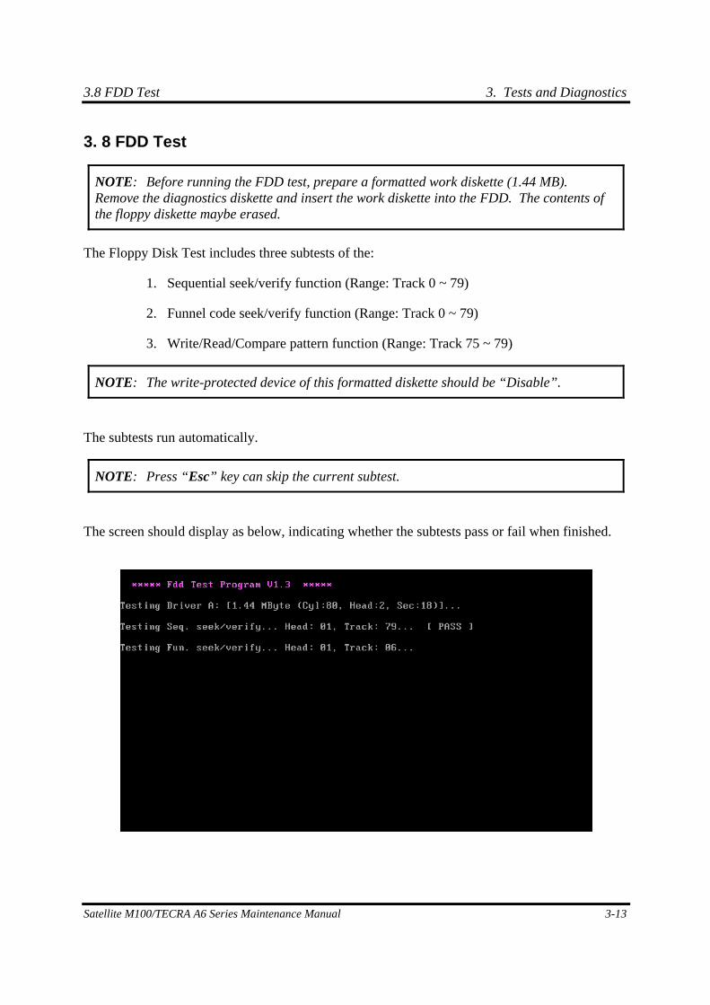
3.8 FDD Test 3. Tests and Diagnostics
Satellite M100/TECRA A6 Series Maintenance Manual 3-13
3. 8 FDD Test
NOTE: Before running the FDD test, prepare a formatted work diskette (1.44 MB). Remove the diagnostics diskette and insert the work diskette into the FDD. The contents of the floppy diskette maybe erased.
The Floppy Disk Test includes three subtests of the:
1. Sequential seek/verify function (Range: Track 0 ~ 79)
2. Funnel code seek/verify function (Range: Track 0 ~ 79)
3. Write/Read/Compare pattern function (Range: Track 75 ~ 79)
NOTE: The write-protected device of this formatted diskette should be “Disable”.
The subtests run automatically.
NOTE: Press “Esc” key can skip the current subtest.
The screen should display as below, indicating whether the subtests pass or fail when finished.
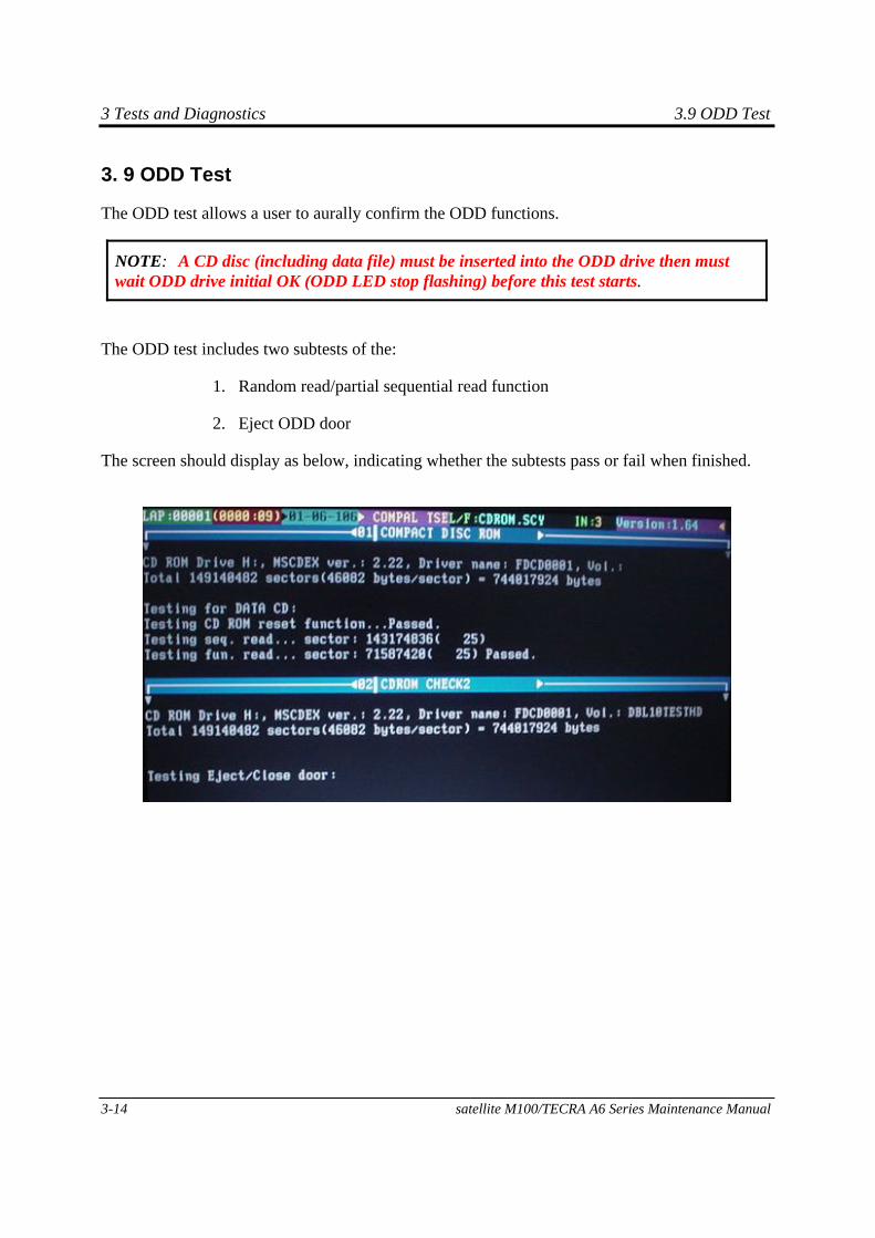
3 Tests and Diagnostics 3.9 ODD Test
3-14 satellite M100/TECRA A6 Series Maintenance Manual
3. 9 ODD Test
The ODD test allows a user to aurally confirm the ODD functions.
NOTE: A CD disc (including data file) must be inserted into the ODD drive then must wait ODD drive initial OK (ODD LED stop flashing) before this test starts.
The ODD test includes two subtests of the:
1. Random read/partial sequential read function
2. Eject ODD door
The screen should display as below, indicating whether the subtests pass or fail when finished.
3.10 Keyboard Test 3. Tests and Diagnostics
Satellite M100/TECRA A6 Series Maintenance Manual 3-15
3. 10 Keyboard Test
The keyboard test checks the all keys function.
NOTE: The Num Lock and the Overlay mode must be off to execute the keyboard test.
Before keyboard test starts, the keyboard matrix code should be chosen as below display:
1. K (UK, for Europe)
2. S (US, for America)
When you execute this test, the keyboard layout is drawn on the display. When any key is pressed, the corresponding key on the screen changes to black as shown below.
It will indicate whether the subtest is passed or failed after the question.
NOTE: The “Fn” key cannot be tested in the keyboard test. To determine whether the “Fn” key is working correctly, press “Fn+F6 ” or “Fn+F7 ” keys to check if LCD display brightness change gradually.
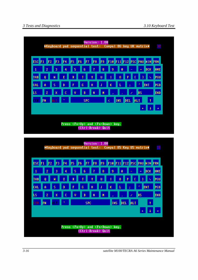
3 Tests and Diagnostics 3.10 Keyboard Test
3-16 satellite M100/TECRA A6 Series Maintenance Manual
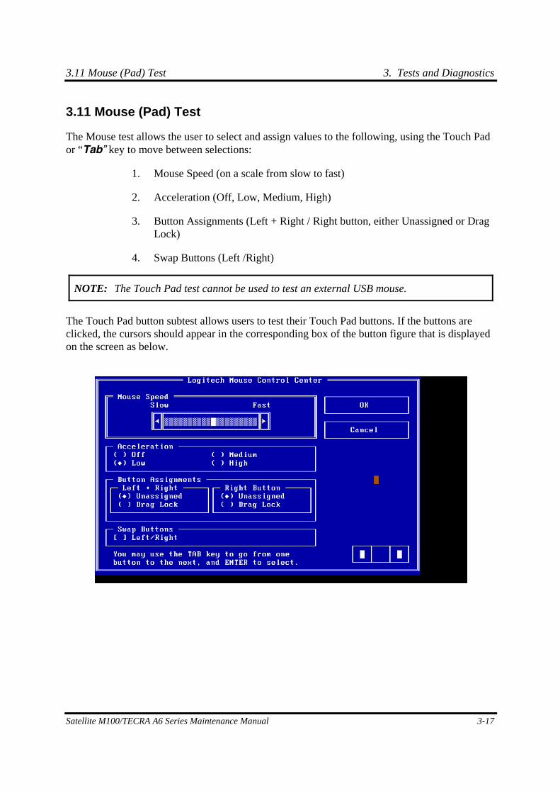
3.11 Mouse (Pad) Test 3. Tests and Diagnostics
Satellite M100/TECRA A6 Series Maintenance Manual 3-17
3.11 Mouse (Pad) Test
The Mouse test allows the user to select and assign values to the following, using the Touch Pad or “Tab” key to move between selections:
1. Mouse Speed (on a scale from slow to fast)
2. Acceleration (Off, Low, Medium, High)
3. Button Assignments (Left + Right / Right button, either Unassigned or Drag Lock)
4. Swap Buttons (Left /Right)
NOTE: The Touch Pad test cannot be used to test an external USB mouse.
The Touch Pad button subtest allows users to test their Touch Pad buttons. If the buttons are clicked, the cursors should appear in the corresponding box of the button figure that is displayed on the screen as below.
3. Tests and Diagnostics 3.11 Mouse (Pad) Test
3-18 satellite M100/TECRA A6 Series Maintenance Manual
After checking T/Pad buttons and cursor’s function, use “Tab” key or use T/Pad cursor to click the “OK” column will end this test.
It will indicate whether the subtests pass or fail after three questions.
NOTE: The above figure has three compartments although the Touch Pad installed may only have two buttons. In this case, the central compartment in the figure does not correspond to any button.

3.12 LCD Pixels Mode Test 3. Tests and Diagnostics
Satellite M100/TECRA A6 Series Maintenance Manual 3-19
3. 12 LCD Pixels Mode Test
This LCD pixels mode test checks whether video display is fine.
This test includes two modes of the test:
1. Text Mode
- including 40*25 (16 colors) and 80*25 (2/16colors).
2. VGA Mode
- including 320*200 (4/16/256 colors), 640*200 (2/16 colors), 640*350 (2/16 colors), 640*480 (2/16/256 colors), 800*600 (256 colors) and 1024*768 (256 colors).
The screen should display as below, indicating whether the test is passed or failed after the question.
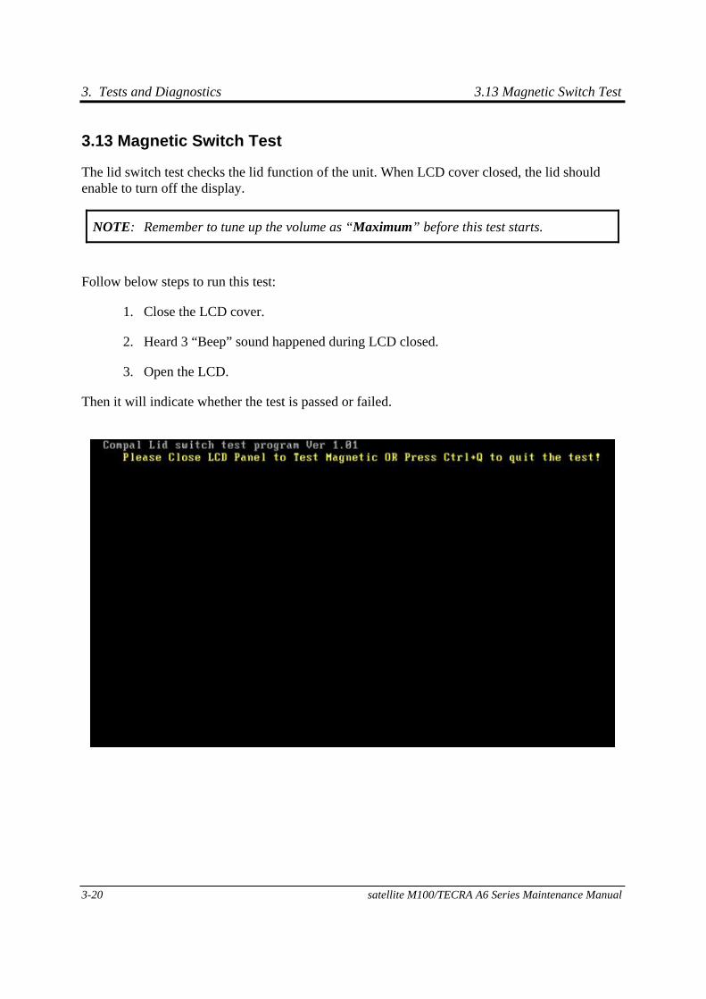
3. Tests and Diagnostics 3.13 Magnetic Switch Test
3-20 satellite M100/TECRA A6 Series Maintenance Manual
3.13 Magnetic Switch Test
The lid switch test checks the lid function of the unit. When LCD cover closed, the lid should enable to turn off the display.
NOTE: Remember to tune up the volume as “Maximum” before this test starts.
Follow below steps to run this test:
1. Close the LCD cover.
2. Heard 3 “Beep” sound happened during LCD closed.
3. Open the LCD.
Then it will indicate whether the test is passed or failed.
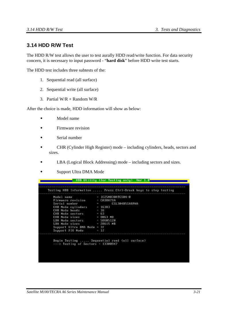
3.14 HDD R/W Test 3. Tests and Diagnostics
Satellite M100/TECRA A6 Series Maintenance Manual 3-21
3.14 HDD R/W Test
The HDD R/W test allows the user to test aurally HDD read/write function. For data security concern, it is necessary to input password - “hard disk” before HDD write test starts.
The HDD test includes three subtests of the:
1. Sequential read (all surface)
2. Sequential write (all surface)
3. Partial W/R + Random W/R
After the choice is made, HDD information will show as below:
Model name
Firmware revision
Serial number
CHR (Cylinder High Register) mode – including cylinders, heads, sectors and sizes.
LBA (Logical Block Addressing) mode – including sectors and sizes.
Support Ultra DMA Mode
3. Tests and Diagnostics 3.14 HDD R/W Test
3-22 satellite M100/TECRA A6 Series Maintenance Manual
NOTE: Press “Ctrl + Break” keys can terminate the current subtest.
The screen should display as previous picture, indicating whether the subtest is passed or failed when finished.
NOTE: The AC adaptor should be connected to successfully run this test.
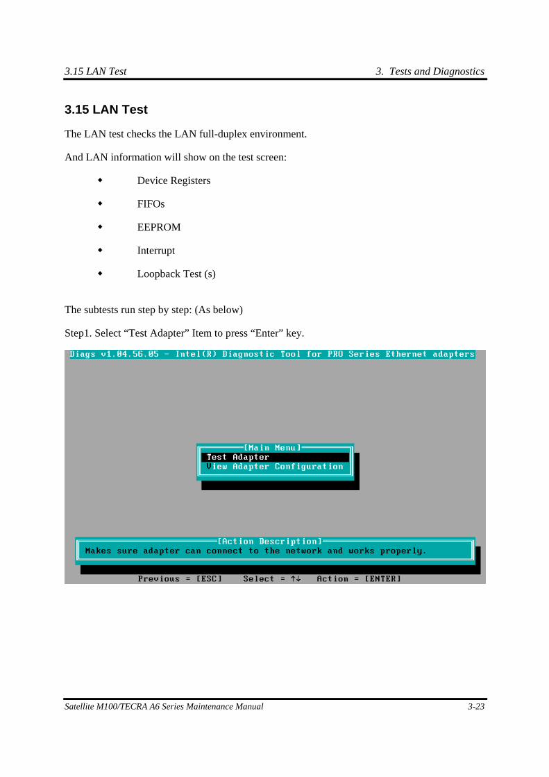
3.15 LAN Test 3. Tests and Diagnostics
Satellite M100/TECRA A6 Series Maintenance Manual 3-23
3.15 LAN Test
The LAN test checks the LAN full-duplex environment.
And LAN information will show on the test screen:
Device Registers
FIFOs
EEPROM
Interrupt
Loopback Test (s)
The subtests run step by step: (As below)
Step1. Select “Test Adapter” Item to press “Enter” key.
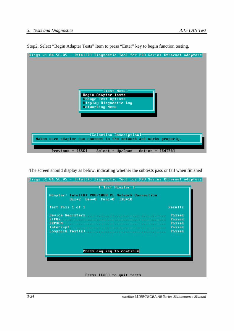
3. Tests and Diagnostics 3.15 LAN Test
3-24 satellite M100/TECRA A6 Series Maintenance Manual
Step2. Select “Begin Adapter Tests” Item to press “Enter” key to begin function testing.
The screen should display as below, indicating whether the subtests pass or fail when finished
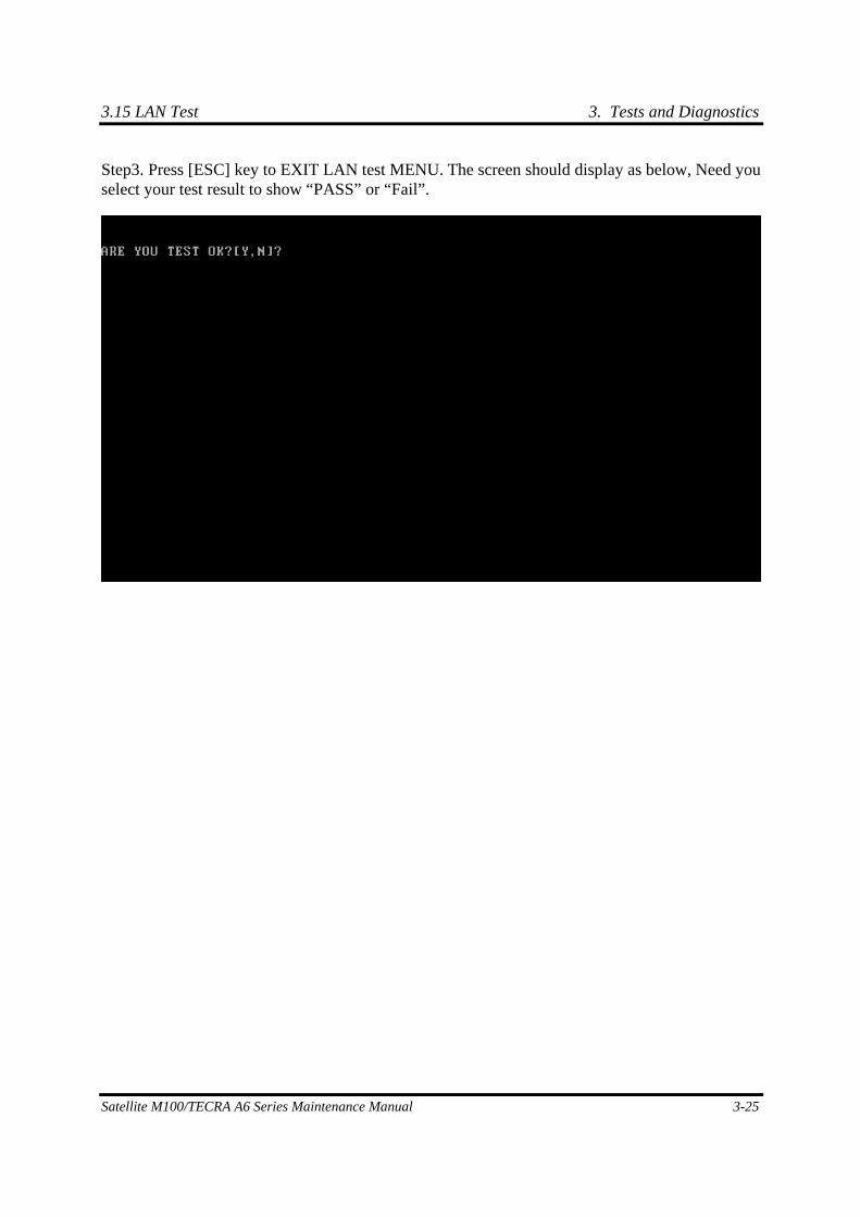
3.15 LAN Test 3. Tests and Diagnostics
Satellite M100/TECRA A6 Series Maintenance Manual 3-25
Step3. Press [ESC] key to EXIT LAN test MENU. The screen should display as below, Need you select your test result to show “PASS” or “Fail”.
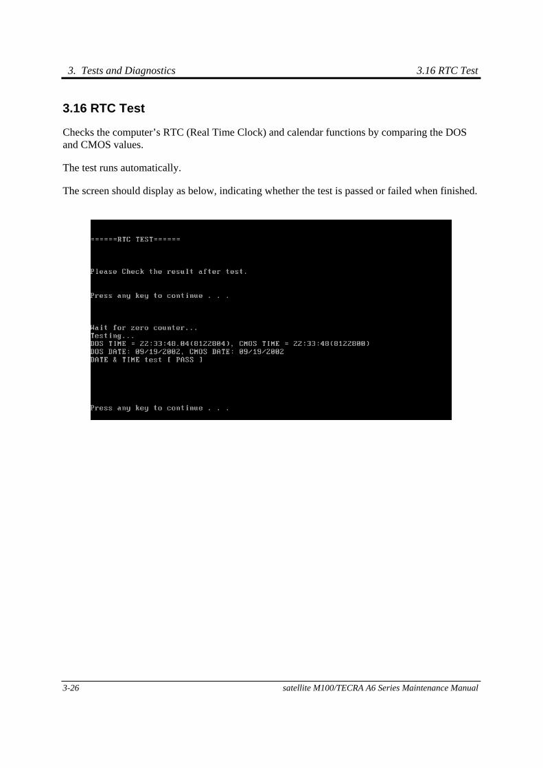
3. Tests and Diagnostics 3.16 RTC Test
3-26 satellite M100/TECRA A6 Series Maintenance Manual
3.16 RTC Test
Checks the computer’s RTC (Real Time Clock) and calendar functions by comparing the DOS and CMOS values.
The test runs automatically.
The screen should display as below, indicating whether the test is passed or failed when finished.
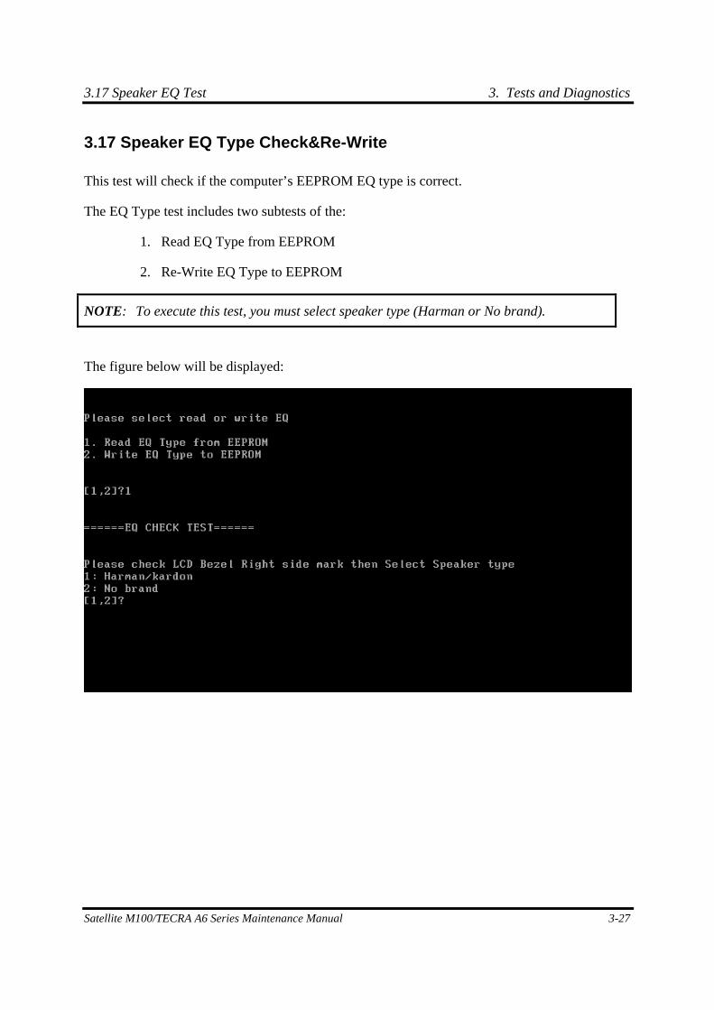
3.17 Speaker EQ Test 3. Tests and Diagnostics
Satellite M100/TECRA A6 Series Maintenance Manual 3-27
3.17 Speaker EQ Type Check&Re-Write
This test will check if the computer’s EEPROM EQ type is correct.
The EQ Type test includes two subtests of the:
1. Read EQ Type from EEPROM
2. Re-Write EQ Type to EEPROM
NOTE: To execute this test, you must select speaker type (Harman or No brand).
The figure below will be displayed:
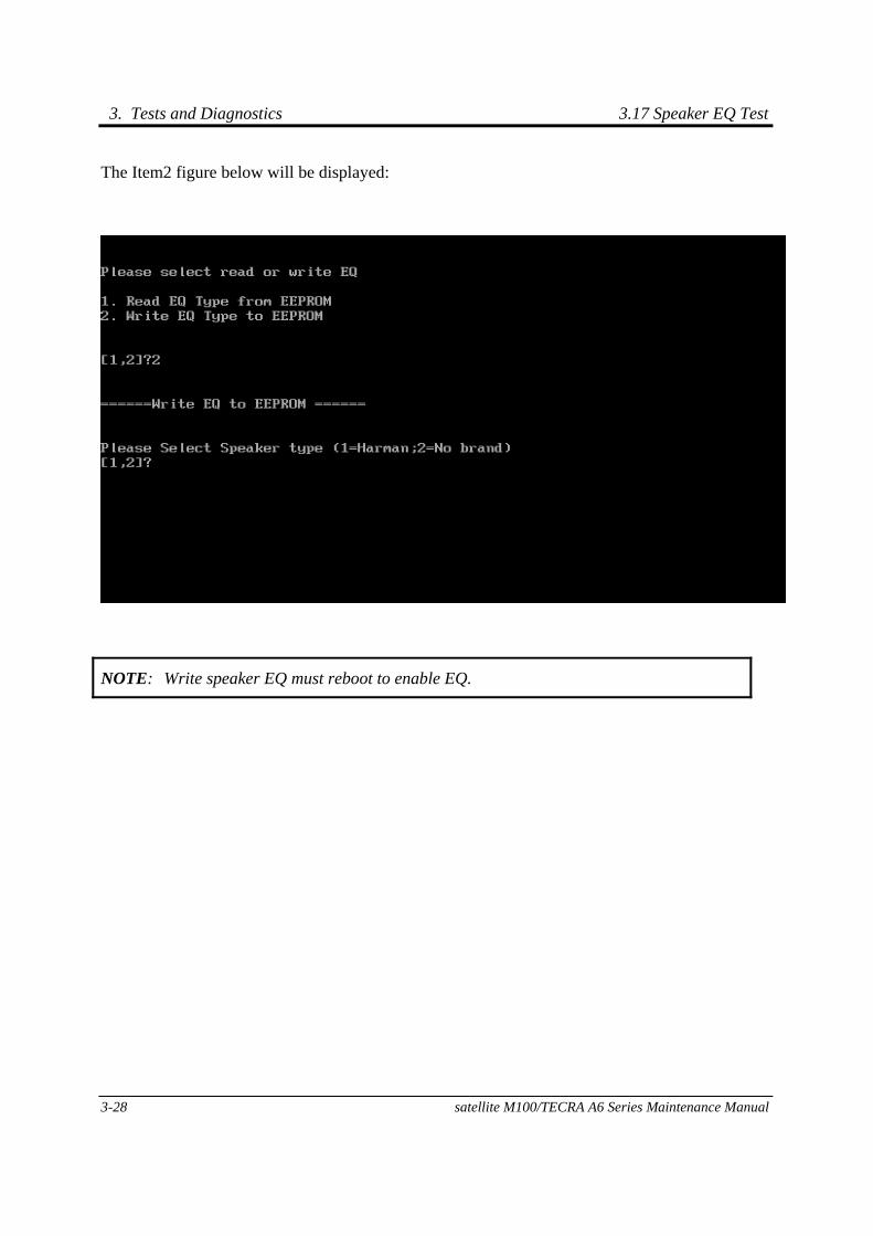
3. Tests and Diagnostics 3.17 Speaker EQ Test
3-28 satellite M100/TECRA A6 Series Maintenance Manual
The Item2 figure below will be displayed:
NOTE: Write speaker EQ must reboot to enable EQ.
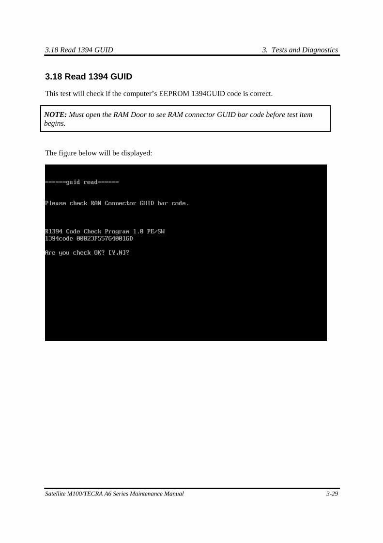
3.18 Read 1394 GUID 3. Tests and Diagnostics
Satellite M100/TECRA A6 Series Maintenance Manual 3-29
3.18 Read 1394 GUID
This test will check if the computer’s EEPROM 1394GUID code is correct.
NOTE: Must open the RAM Door to see RAM connector GUID bar code before test item begins.
The figure below will be displayed:
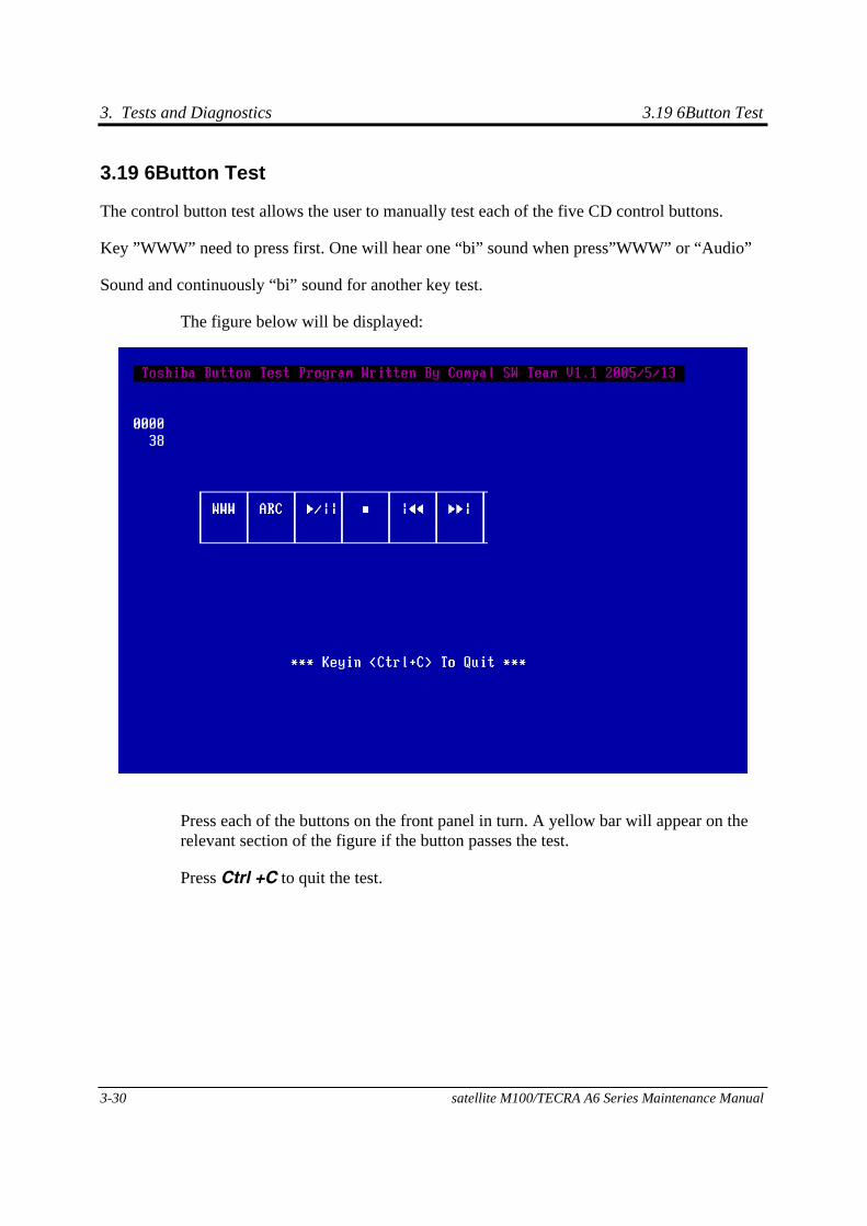
3. Tests and Diagnostics 3.19 6Button Test
3-30 satellite M100/TECRA A6 Series Maintenance Manual
3.19 6Button Test
The control button test allows the user to manually test each of the five CD control buttons.
Key ”WWW” need to press first. One will hear one “bi” sound when press”WWW” or “Audio”
Sound and continuously “bi” sound for another key test.
The figure below will be displayed:
Press each of the buttons on the front panel in turn. A yellow bar will appear on the relevant section of the figure if the button passes the test.
Press Ctrl +C to quit the test.
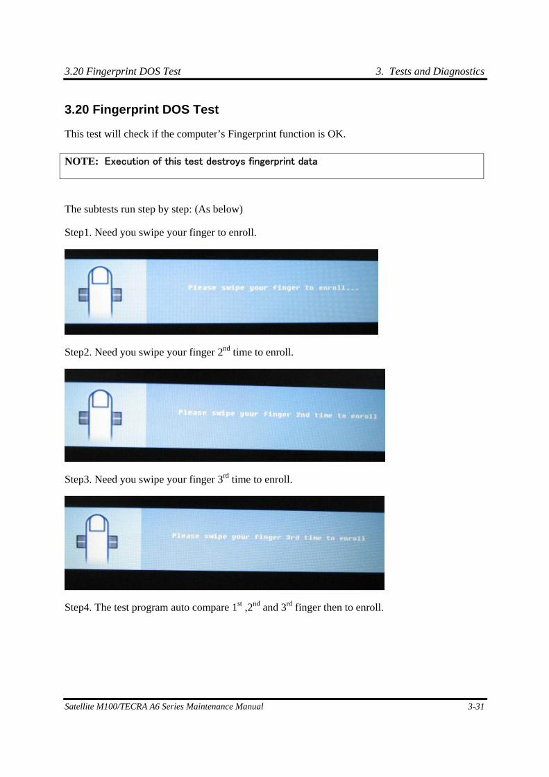
3.20 Fingerprint DOS Test 3. Tests and Diagnostics
Satellite M100/TECRA A6 Series Maintenance Manual 3-31
3.20 Fingerprint DOS Test
This test will check if the computer’s Fingerprint function is OK.
The subtests run step by step: (As below)
Step1. Need you swipe your finger to enroll.
Step2. Need you swipe your finger 2nd time to enroll.
Step3. Need you swipe your finger 3rd time to enroll.
Step4. The test program auto compare 1st ,2nd and 3rd finger then to enroll.
NOTE: Execution of this test destroys fingerprint data
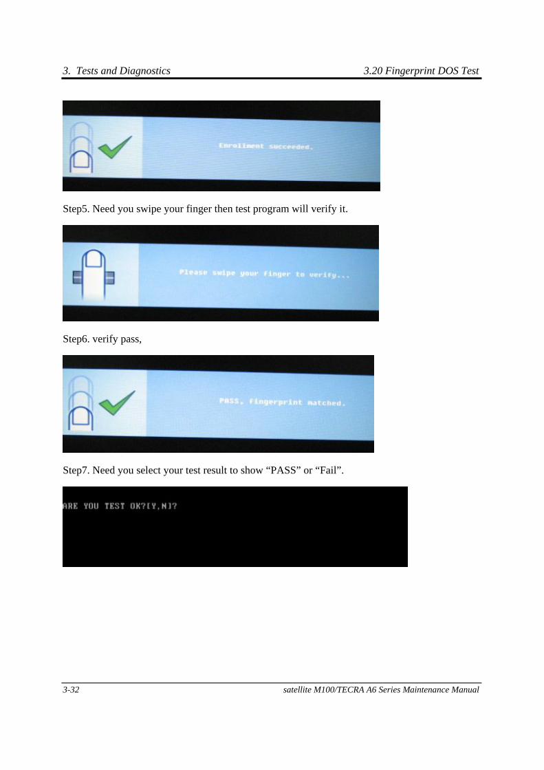
3. Tests and Diagnostics 3.20 Fingerprint DOS Test
3-32 satellite M100/TECRA A6 Series Maintenance Manual
Step5. Need you swipe your finger then test program will verify it.
Step6. verify pass,
Step7. Need you select your test result to show “PASS” or “Fail”.
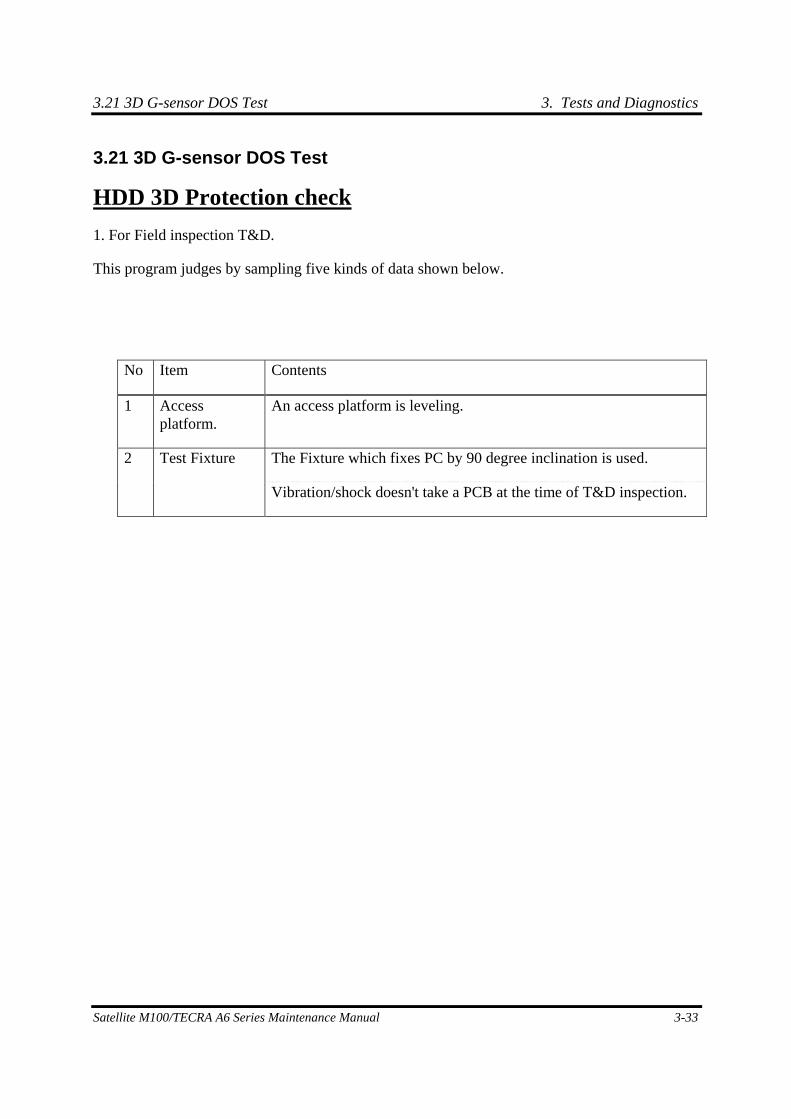
3.21 3D G-sensor DOS Test 3. Tests and Diagnostics
Satellite M100/TECRA A6 Series Maintenance Manual 3-33
3.21 3D G-sensor DOS Test
HDD 3D Protection check
1. For Field inspection T&D.
This program judges by sampling five kinds of data shown below.
No Item Contents
1 Access platform.
An access platform is leveling.
The Fixture which fixes PC by 90 degree inclination is used. 2 Test Fixture
Vibration/shock doesn't take a PCB at the time of T&D inspection.
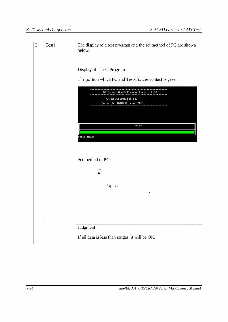
3. Tests and Diagnostics 3.21 3D G-sensor DOS Test
3-34 satellite M100/TECRA A6 Series Maintenance Manual
The display of a test program and the set method of PC are shown below.
Display of a Test Program
The portion which PC and Test-Fixture contact is green.
Set method of PC
3 Test1
Judgment
If all data is less than ranges, it will be OK.
X
Z
Upper

3.21 3D G-sensor DOS Test 3. Tests and Diagnostics
Satellite M100/TECRA A6 Series Maintenance Manual 3-35
The display of a test program and the set method of PC are shown below.
Display of a Test Program
Set method of PC
4 Test2
Judgment
If all data is less than ranges, it will be OK.
Upper
Rear
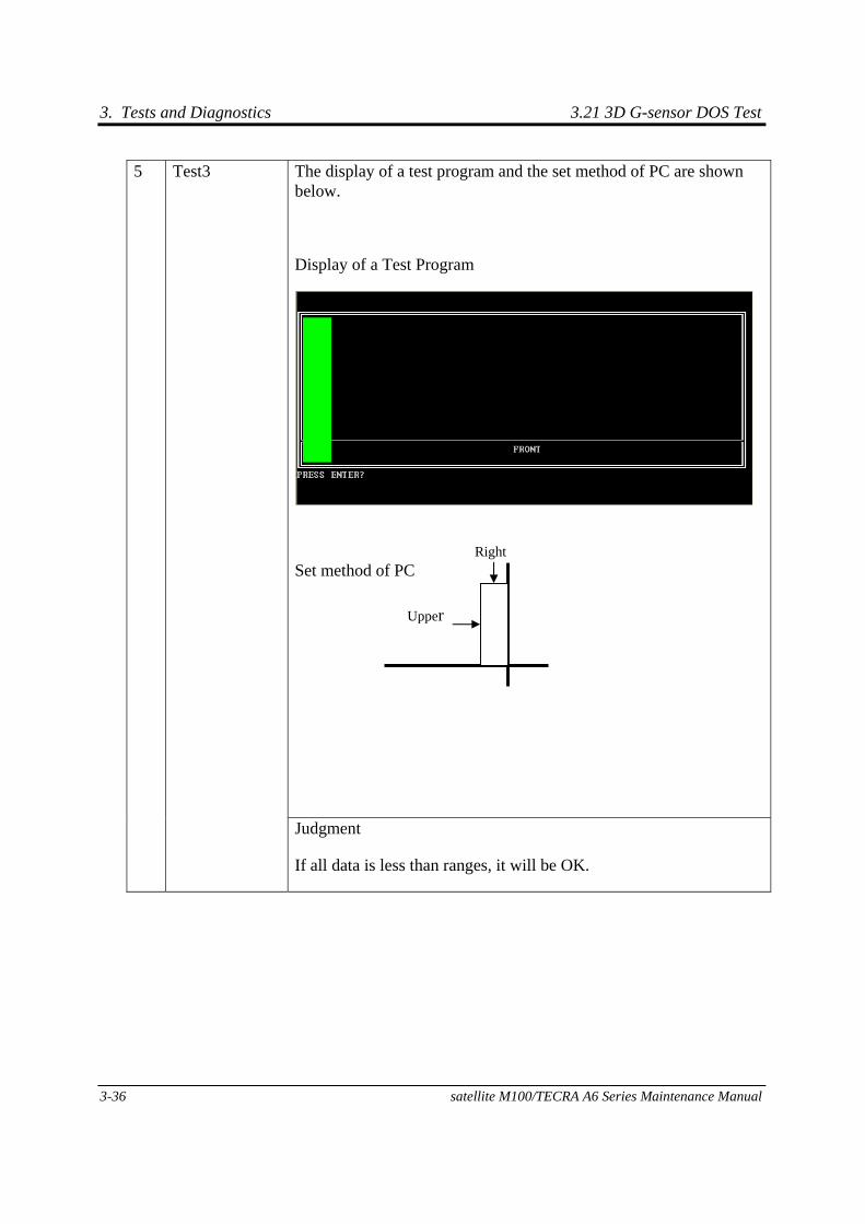
3. Tests and Diagnostics 3.21 3D G-sensor DOS Test
3-36 satellite M100/TECRA A6 Series Maintenance Manual
The display of a test program and the set method of PC are shown below.
Display of a Test Program
Set method of PC
5 Test3
Judgment
If all data is less than ranges, it will be OK.
Upper
Right
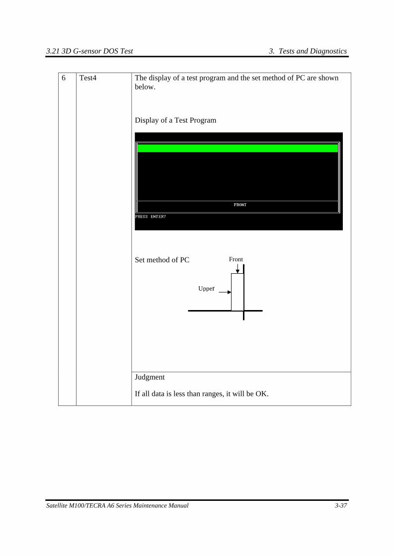
3.21 3D G-sensor DOS Test 3. Tests and Diagnostics
Satellite M100/TECRA A6 Series Maintenance Manual 3-37
The display of a test program and the set method of PC are shown below.
Display of a Test Program
Set method of PC
6 Test4
Judgment
If all data is less than ranges, it will be OK.
Upper
Front
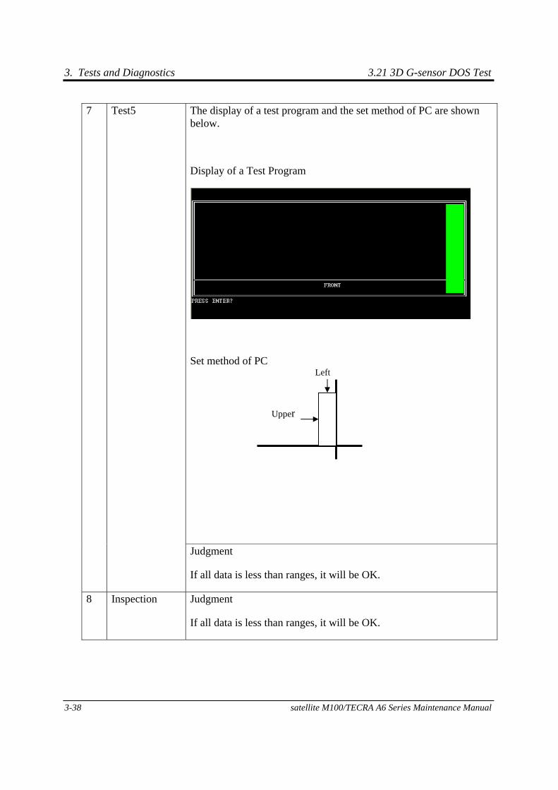
3. Tests and Diagnostics 3.21 3D G-sensor DOS Test
3-38 satellite M100/TECRA A6 Series Maintenance Manual
The display of a test program and the set method of PC are shown below.
Display of a Test Program
Set method of PC
7 Test5
Judgment
If all data is less than ranges, it will be OK.
8 Inspection Judgment
If all data is less than ranges, it will be OK.
Upper
Left
3.21 3D G-sensor DOS Test 3. Tests and Diagnostics
Satellite M100/TECRA A6 Series Maintenance Manual 3-39
9 Setting Calibration data
When an inspection result is O.K., calibration at HPC.
2. Test Result
A test result is displayed when a test is completed. A display of result is O.K. or NG.
And an error flag is returned at the end of a program.
OK is 0.
NG is 1.
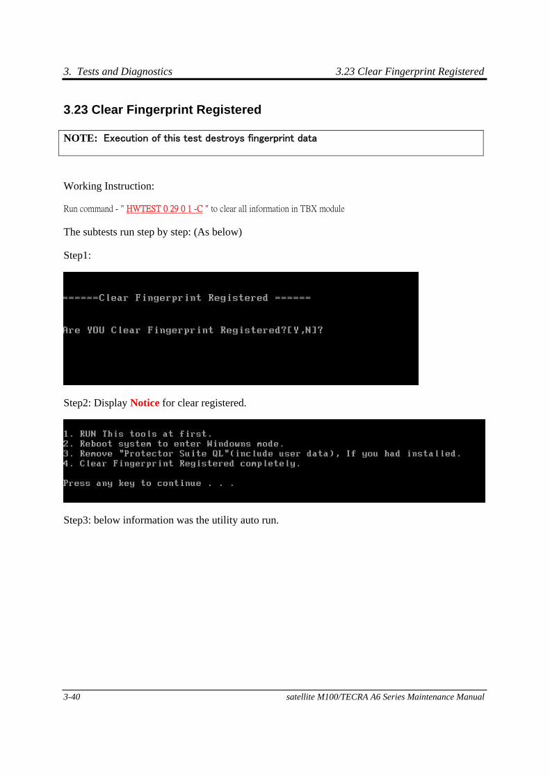
3. Tests and Diagnostics 3.23 Clear Fingerprint Registered
3-40 satellite M100/TECRA A6 Series Maintenance Manual
3.23 Clear Fingerprint Registered
Working Instruction:
Run command - " HWTEST 0 29 0 1 -C " to clear all information in TBX module
The subtests run step by step: (As below)
Step1:
Step2: Display Notice for clear registered.
Step3: below information was the utility auto run.
NOTE: Execution of this test destroys fingerprint data
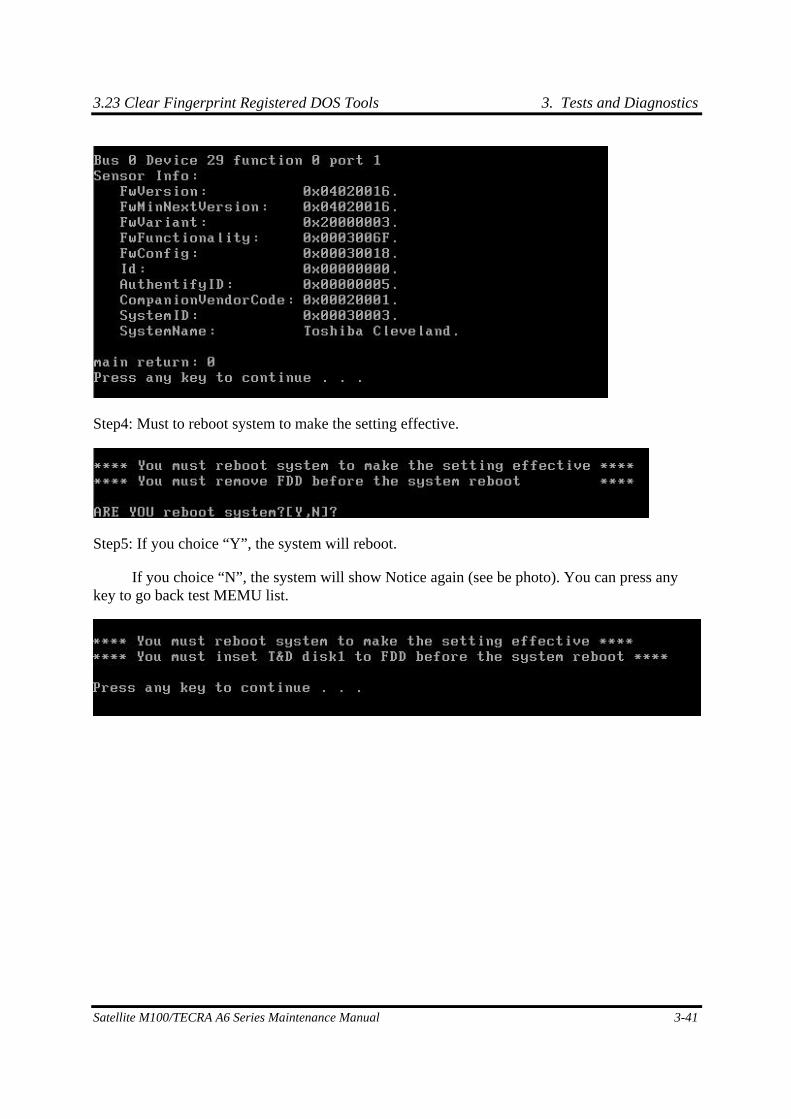
3.23 Clear Fingerprint Registered DOS Tools 3. Tests and Diagnostics
Satellite M100/TECRA A6 Series Maintenance Manual 3-41
Step4: Must to reboot system to make the setting effective.
Step5: If you choice “Y”, the system will reboot.
If you choice “N”, the system will show Notice again (see be photo). You can press any key to go back test MEMU list.

3. Tests and Diagnostics 3.23 Clear Fingerprint Registered DOS Tools
3-42 satellite M100/TECRA A6 Series Maintenance Manual
[CONFIDENTIAL]
Chapter 4 Replacement Procedures
4. Replacement Procedures
4-ii [CONFIDENTIAL] Tecra A6 Maintenance Manual
4
Tecra A6 Maintenance Manual [CONFIDENTIAL] 4-iii
Chapter 4 Contents
4.1 General......................................................................................................................... 4-1
4.2 Battery .......................................................................................................................... 4-7
4.3 PC Card........................................................................................................................ 4-9
4.4 Memory Card............................................................................................................. 4-11
4.5 HDD ........................................................................................................................... 4-13
4.6 Expansion Memory ................................................................................................... 4-15
4.7 Optical Drive Module ................................................................................................ 4-18
4.8 Optical Drive.............................................................................................................. 4-20
4.9 Keyboard .................................................................................................................... 4-22
4.10 Direct play button board............................................................................................ 4-26
4.11 Bluetooth module ...................................................................................................... 4-28
4.12 Memory ...................................................................................................................... 4-32
4.13 Wireless LAN Unit..................................................................................................... 4-35
4.14 Modem ....................................................................................................................... 4-39
4.15 Display Assembly....................................................................................................... 4-42
4.16 Top Cover................................................................................................................... 4-45
4.17 Touch Pad.................................................................................................................. 4-49
4.18 Fingerprint Module................................................................................................... 4-51
4.19 Speakers ..................................................................................................................... 4-53
4.20 USB Board................................................................................................................. 4-55
4.21 System Board ............................................................................................................. 4-57
4.22 VGA Module .............................................................................................................. 4-60
4.23 Fan & CPU................................................................................................................ 4-62
4.24 Display Mask ............................................................................................................. 4-67
4.25 FL Inverter Board ..................................................................................................... 4-69
4.26 LCD Module .............................................................................................................. 4-72
4 Replacement Procedures
4-iv [CONFIDENTIAL] Tecra A6 Maintenance Manual
Figures
Figure 4-1 Unlocking the battery lock .............................................................................4-7
Figure 4-2 Removing the battery pack.............................................................................4-7
Figure 4-3 Removing the PC card....................................................................................4-9
Figure 4-4 Installing the PC card ...................................................................................4-10
Figure 4-5 Pressing the Memory Card ...........................................................................4-11
Figure 4-6 Removing the Memory Card........................................................................4-11
Figure 4-7 Installing the Memory Card .........................................................................4-12
Figure 4-8 HDD .............................................................................................................4-13
Figure 4-9 Releasing the HDD door screw....................................................................4-13
Figure 4-10 Removing the HDD door .............................................................................4-14
Figure 4-11 Removing the HDD......................................................................................4-14
Figure 4-12 Releasing the cover screw ............................................................................4-15
Figure 4-13 Removing the expansion memory module cover .........................................4-15
Figure 4-14 Releasing the memory module .....................................................................4-16
Figure 4-15 Removing the expansion memory module ...................................................4-16
Figure 4-16 Removing the optical drive screw................................................................4-18
Figure 4-17 Removing the optical drive module .............................................................4-18
Figure 4-18 Removing the optical drive bracket .............................................................4-20
Figure 4-19 Removing the strip cover .............................................................................4-22
Figure 4-20 Removing the strip cover .............................................................................4-22
Figure 4-21 Removing the keyboard screws....................................................................4-23
Figure 4-22 Removing the keyboard screws....................................................................4-23
Figure 4-23 Disconnecting the keyboard cable................................................................4-24
Figure 4-24 Removing the keyboard................................................................................4-24
Figure 4-25 Removing the Direct Play Button Board......................................................4-26
Figure 4-26 Removing the Direct Play Button Board cable ............................................4-26
Figure 4-27 Removing the Bluetooth module screw .......................................................4-28
Figure 4-28 Disconnecting the FFC cable .......................................................................4-28
Figure 4-29 Lifting the Bluetooth module .......................................................................4-29
Tecra A6 Maintenance Manual [CONFIDENTIAL] 4-v
Figure 4-30 Removing the Bluetooth module ................................................................. 4-29
Figure 4-31 Disconnecting the Bluetooth connector....................................................... 4-30
Figure 4-32 Removing the Bluetooth module cable........................................................ 4-30
Figure 4-33 Removing the shield cover screws............................................................... 4-32
Figure 4-34 Removing the memory module.................................................................... 4-32
Figure 4-35 Removing the memory module.................................................................... 4-33
Figure 4-36 Removing the wireless LAN unit screw ...................................................... 4-35
Figure 4-37 Removing the wireless LAN door ............................................................... 4-35
Figure 4-38 Removing the WLAN module screws ......................................................... 4-36
Figure 4-39 Removing the wireless LAN antenna connectors........................................ 4-36
Figure 4-40 Releasing the wireless LAN unit ................................................................. 4-37
Figure 4-41 Removing the modem cover screw.............................................................. 4-39
Figure 4-42 Removing the modem cover ........................................................................ 4-39
Figure 4-43 Removing the modem module screws ......................................................... 4-40
Figure 4-44 Removing the modem module ..................................................................... 4-40
Figure 4-45 Disconnecting cables ................................................................................... 4-42
Figure 4-46 Disconnecting the rear screws ..................................................................... 4-42
Figure 4-47 Removing the front screws .......................................................................... 4-43
Figure 4-48 Removing the display assembly................................................................... 4-43
Figure 4-49 Removing the top cover (back panel screws) .............................................. 4-45
Figure 4-50 Removing the top cover (front panel screws) .............................................. 4-46
Figure 4-51 Removing the cables .................................................................................... 4-46
Figure 4-52 Removing the top cover ............................................................................... 4-47
Figure 4-53 Removing the touch pad screw.................................................................... 4-49
Figure 4-54 Removing the touch pad bracket ................................................................. 4-49
Figure 4-55 Removing the touch pad .............................................................................. 4-50
Figure 4-56 Removing the fingerprint module bracket screws ....................................... 4-51
Figure 4-57 Removing the fingerprint module bracket ................................................... 4-51
Figure 4-58 Removing the fingerprint module................................................................ 4-52
Figure 4-59 Removing the speaker screws...................................................................... 4-53
Figure 4-60 Removing the speakers ................................................................................ 4-53
Figure 4-61 Removing the USB Board screws................................................................ 4-55
4 Replacement Procedures
4-vi [CONFIDENTIAL] Tecra A6 Maintenance Manual
Figure 4-62 Removing the USB Board cable ..................................................................4-55
Figure 4-63 Removing the USB Board............................................................................4-56
Figure 4-64 Removing the cable ......................................................................................4-57
Figure 4-65 Removing the hexagonal screws ..................................................................4-57
Figure 4-66 Removing the system board .........................................................................4-58
Figure 4-67 Removing the VGA module screws.............................................................4-60
Figure 4-68 Removing the VGA module.........................................................................4-60
Figure 4-69 Removing the VGA module heat sink .........................................................4-61
Figure 4-70 Removing the heat sink screws ....................................................................4-62
Figure 4-71 Removing the heat sink ................................................................................4-62
Figure 4-72 Removing the fan connector.........................................................................4-63
Figure 4-73 Removing the fan screw from the top side of the system board ..................4-63
Figure 4-74 Removing the fan .........................................................................................4-64
Figure 4-75 Turning the CPU cam...................................................................................4-64
Figure 4-76 Removing the CPU.......................................................................................4-65
Figure 4-77 Removing the display mask screws..............................................................4-67
Figure 4-78 Removing the display mask .........................................................................4-67
Figure 4-79 Removing the screws....................................................................................4-69
Figure 4-80 Removing the connectors .............................................................................4-69
Figure 4-81 Removing the FL inverter board ..................................................................4-70
Figure 4-82 Removing the LVDS cable screw ................................................................4-72
Figure 4-83 Removing the LCD Module .........................................................................4-72
Figure 4-84 Removing the bracket screws.......................................................................4-73
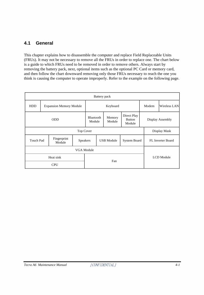
Tecra A6 Maintenance Manual [CONFIDENTIAL] 4-1
4.1 General
This chapter explains how to disassemble the computer and replace Field Replaceable Units (FRUs). It may not be necessary to remove all the FRUs in order to replace one. The chart below is a guide to which FRUs need to be removed in order to remove others. Always start by removing the battery pack, next, optional items such as the optional PC Card or memory card, and then follow the chart downward removing only those FRUs necessary to reach the one you think is causing the computer to operate improperly. Refer to the example on the following page.
Battery pack
HDD Expansion Memory Module Keyboard Modem Wireless LAN
ODD Bluetooth Module
Memory Module
Direct Play Button Module
Display Assembly
Top Cover Display Mask
Touch Pad Fingerprint Module Speakers USB Module System Board FL Inverter Board
VGA Module
Heat sink
CPU Fan
LCD Module
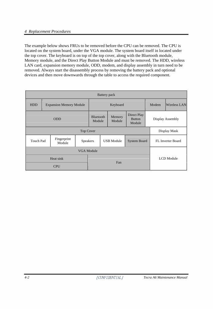
4 Replacement Procedures
4-2 [CONFIDENTIAL] Tecra A6 Maintenance Manual
The example below shows FRUs to be removed before the CPU can be removed. The CPU is located on the system board, under the VGA module. The system board itself in located under the top cover. The keyboard is on top of the top cover, along with the Bluetooth module, Memory module, and the Direct Play Button Module and must be removed. The HDD, wireless LAN card, expansion memory module, ODD, modem, and display assembly in turn need to be removed. Always start the disassembly process by removing the battery pack and optional devices and then move downwards through the table to access the required component.
Battery pack
HDD Expansion Memory Module Keyboard Modem Wireless LAN
ODD Bluetooth Module
Memory Module
Direct Play Button Module
Display Assembly
Top Cover Display Mask
Touch Pad Fingerprint Module Speakers USB Module System Board FL Inverter Board
VGA Module
Heat sink
CPU Fan
LCD Module
Tecra A6 Maintenance Manual [CONFIDENTIAL] 4-3
Safety Precautions
Before you begin disassembly, read the following safety precautions and observe them carefully as you work.
DANGER: 1. Always use the lithium ion battery pack or a backup battery that is authorized by
Toshiba or is compatible with the unit. Since other battery packs have different specifications, they may be incompatible with the unit, and may burst or explode. Heating or disassembling the battery pack could cause leakage of alkaline solution. Throwing the battery pack into a fire could cause the battery pack to explode.
2. The power supply, FL inverter and other components carry high voltages. To avoid the risk of electric shock when you need to turn on the power of a partially disassembled computer to check its operation, be very careful not to touch connectors or components. Also, do not disassemble individual components for first-level maintenance.
WARNING: To avoid the risk of electric shock or other injury: 1. Always turn the power off and disconnect the AC adaptor from the power source. 2. Remove any metal jewelry or accessories such as watches, necklaces, bracelets, or
rings. Batteries in the computer retain an electrical charge so there is a danger of electrical shock even when the computer is disconnected from an AC power source.
3. Never work with wet or damp hands. 4. The computer contains sharp edges and corners. Be careful not to injure yourself. 5. Make sure that all replacement components meet the specifications for the computer
and that all cables and connectors are securely fastened.
CAUTION: To avoid damage to the computer: 1. When you change a component, make sure that the replacement component meets the
required specifications. Never use foreign or incompatible parts. 2. Metal objects such as screws or paper clips which fall into the unit can cause a short-
circuit, fire, or other internal damage. 3. When assembling the computer, make sure you use the correct screws to secure the
various pieces in place. Screw sizes are listed in their corresponding figure. Make sure all screws are securely fastened. Loose screws can cause short circuits, resulting in heat, smoke, or fire.
4. Before removing an FRU or other component, make sure all cables to the component have been disconnected.
5. If you use AC power, be sure to use the cable that came with the computer or one recommended by Toshiba.
4 Replacement Procedures
4-4 [CONFIDENTIAL] Tecra A6 Maintenance Manual
Before You Begin
Look over the procedures in this section before you begin disassembling the computer. Familiarize yourself with the disassembly and reassembly steps. Begin each procedure by removing the AC adaptor and the battery pack as instructed in section 4.2.
1. Do not disassemble the computer unless it is operating abnormally.
2. Use only the correct and approved tools.
3. Make sure the working environment is free from the following elements whether you are using or storing the computer.
Dust and contaminates
Static electricity
Extreme heat, cold and humidity 4. Make sure the FRU you are replacing is causing the abnormal operation by performing the
necessary troubleshooting and diagnostics tests described in chapters 2 and 3 of this manual.
5. Do not perform any operations that are not necessary and use only the described procedures for disassembling and installing FRUs in the computer.
6. After removing parts from the computer, place them in a safe place away from the computer so they will not be damaged and will not interfere with your work.
7. You will remove and replace many screws when you disassemble the computer. When you remove screws, make sure they are placed in a safe place and identified with the correct parts.
8. When assembling the computer make sure you use the correct screws to secure the various pieces. Screw sizes are listed in their corresponding figures.
9. The computer contains many sharp edges and corners, so be careful not to injure yourself.
10. After you have replaced an FRU, make sure the computer is functioning properly by performing the appropriate test on the FRU you have fixed or replaced.
Tecra A6 Maintenance Manual [CONFIDENTIAL] 4-5
Disassembly Procedures
The computer has two basic types of cable connectors:
Pressure Plate Connectors
Standard Pin Connectors
To disconnect a Pressure Plate connector, lift up the tabs on either side of the connector’s plastic pressure plate and slide the cable out of the connector. To connect the cable to a Pressure Plate connector, make sure the pressure plate is fully lifted and slide the cable into the connector. Secure the cable in place by pushing the sides of the pressure plate down so the plate is flush with the sides of the connector. Gently pull on the cable to make sure the cable is secure. If you pull out the connector, connect it again making sure the connector’s pressure plate is fully lifted when you insert the cable.
Standard pin connectors are used with all other cables. These connectors can be connected and disconnected by simply pulling them apart or pushing them together.
Assembly Procedures
After you have disassembled the computer and fixed or repaired the problem that was causing the computer to operate abnormally, you will need to reassemble the computer.
Install all the removed FRUs following the steps described in the corresponding sections in this chapter.
While assembling the computer, remember the following general points:
Take your time, making sure you follow the instructions closely. Most problems arise when you get in a hurry assembling the computer.
Make sure all cables and connectors are securely fastened.
Before securing the FRU or other parts, make sure that no cables are pinched by screws or the FRUs.
Check that all latches are closed securely.
Make sure all the correct screws are used to secure all FRUs. Using the wrong screw can either damage the threads on the screw or the head of the screw and may prevent proper seating of an FRU.
After installing an FRU in the computer, confirm that the FRU and the computer are functioning properly.
4 Replacement Procedures
4-6 [CONFIDENTIAL] Tecra A6 Maintenance Manual
Tools and Equipment
The use of Electrostatic Discharge (ESD) equipment is very important for your safety and the safety of those around you. Proper use of these devices will increase the success rate of your repairs and lower the cost for damaged or destroyed parts. The following equipment is necessary to disassemble and reassemble the computer:
One M2 Phillips screwdriver to remove and replace screws.
One T5 security screwdriver.
Tweezers, to lift out screws that you cannot grasp with your fingers.
ESD mats for the floor and the table you are working on.
ESD wrist strap or heel grounder.
Anti-static carpeting or flooring.
Air-ionizers in highly static sensitive areas.
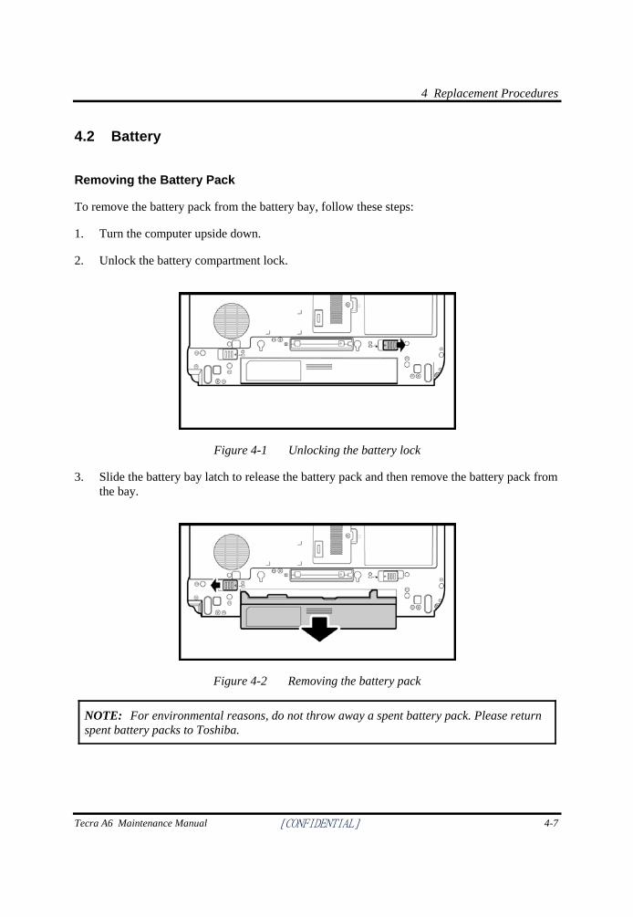
4 Replacement Procedures
Tecra A6 Maintenance Manual [CONFIDENTIAL] 4-7
4.2 Battery
Removing the Battery Pack
To remove the battery pack from the battery bay, follow these steps:
1. Turn the computer upside down.
2. Unlock the battery compartment lock.
Figure 4-1 Unlocking the battery lock
3. Slide the battery bay latch to release the battery pack and then remove the battery pack from the bay.
Figure 4-2 Removing the battery pack
NOTE: For environmental reasons, do not throw away a spent battery pack. Please return spent battery packs to Toshiba.
4 Replacement Procedures
4-8 [CONFIDENTIAL] Tecra A6 Maintenance Manual
Installing the Battery Pack
To install the battery pack in the battery bay, follow these steps and refer to the figures in the preceding section.
WARNING: The battery is a lithium ion battery and can explode if not properly replaced, used, handled or disposed of. Use only batteries recommended by Toshiba as replacements.
1. Slide the battery pack into the battery bay. The battery bay latch will click automatically.
2. Lock the battery double lock to secure the battery pack in position.
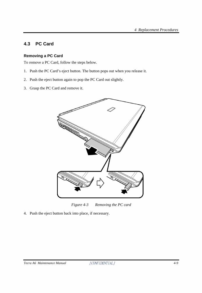
4 Replacement Procedures
Tecra A6 Maintenance Manual [CONFIDENTIAL] 4-9
4.3 PC Card
Removing a PC Card To remove a PC Card, follow the steps below.
1. Push the PC Card’s eject button. The button pops out when you release it.
2. Push the eject button again to pop the PC Card out slightly.
3. Grasp the PC Card and remove it.
Figure 4-3 Removing the PC card
4. Push the eject button back into place, if necessary.
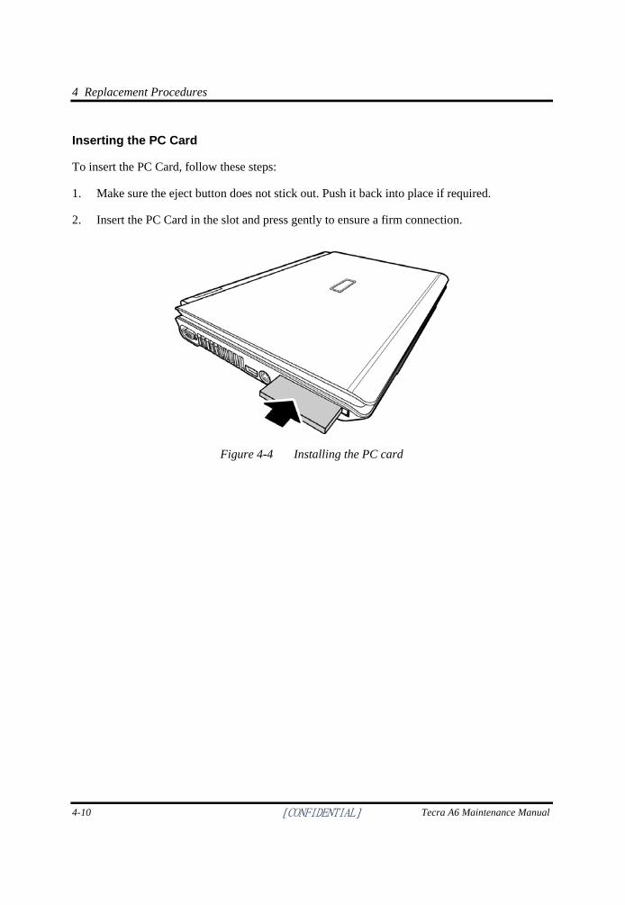
4 Replacement Procedures
4-10 [CONFIDENTIAL] Tecra A6 Maintenance Manual
Inserting the PC Card
To insert the PC Card, follow these steps:
1. Make sure the eject button does not stick out. Push it back into place if required.
2. Insert the PC Card in the slot and press gently to ensure a firm connection.
Figure 4-4 Installing the PC card
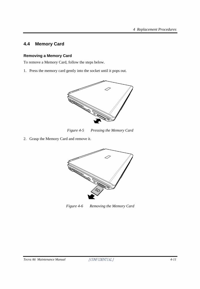
4 Replacement Procedures
Tecra A6 Maintenance Manual [CONFIDENTIAL] 4-11
4.4 Memory Card
Removing a Memory Card To remove a Memory Card, follow the steps below.
1. Press the memory card gently into the socket until it pops out.
Figure 4-5 Pressing the Memory Card
2. Grasp the Memory Card and remove it.
Figure 4-6 Removing the Memory Card
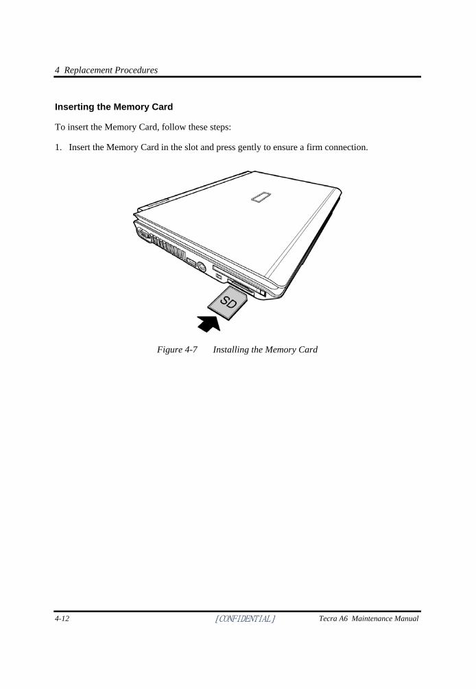
4 Replacement Procedures
4-12 [CONFIDENTIAL] Tecra A6 Maintenance Manual
Inserting the Memory Card
To insert the Memory Card, follow these steps:
1. Insert the Memory Card in the slot and press gently to ensure a firm connection.
Figure 4-7 Installing the Memory Card
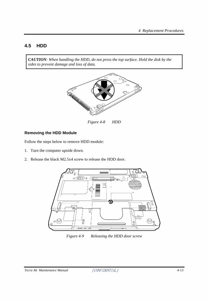
4 Replacement Procedures
Tecra A6 Maintenance Manual [CONFIDENTIAL] 4-13
4.5 HDD
CAUTION: When handling the HDD, do not press the top surface. Hold the disk by the sides to prevent damage and loss of data.
Figure 4-8 HDD
Removing the HDD Module
Follow the steps below to remove HDD module:
1. Turn the computer upside down.
2. Release the black M2.5x4 screw to release the HDD door.
Figure 4-9 Releasing the HDD door screw
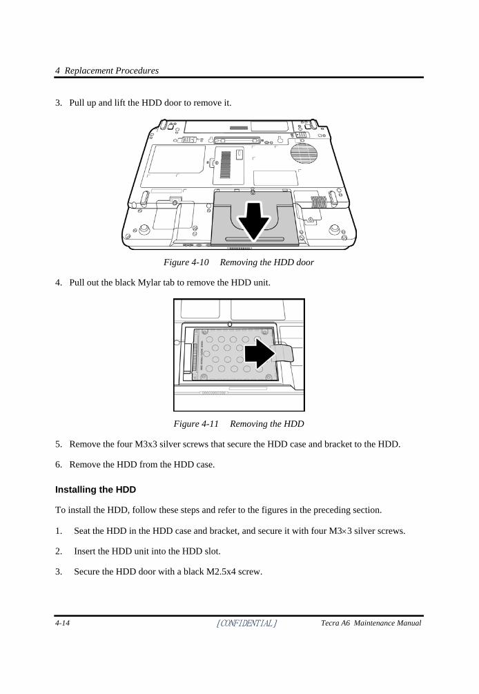
4 Replacement Procedures
4-14 [CONFIDENTIAL] Tecra A6 Maintenance Manual
3. Pull up and lift the HDD door to remove it.
Figure 4-10 Removing the HDD door
4. Pull out the black Mylar tab to remove the HDD unit.
Figure 4-11 Removing the HDD
5. Remove the four M3x3 silver screws that secure the HDD case and bracket to the HDD.
6. Remove the HDD from the HDD case.
Installing the HDD
To install the HDD, follow these steps and refer to the figures in the preceding section.
1. Seat the HDD in the HDD case and bracket, and secure it with four M3×3 silver screws.
2. Insert the HDD unit into the HDD slot.
3. Secure the HDD door with a black M2.5x4 screw.
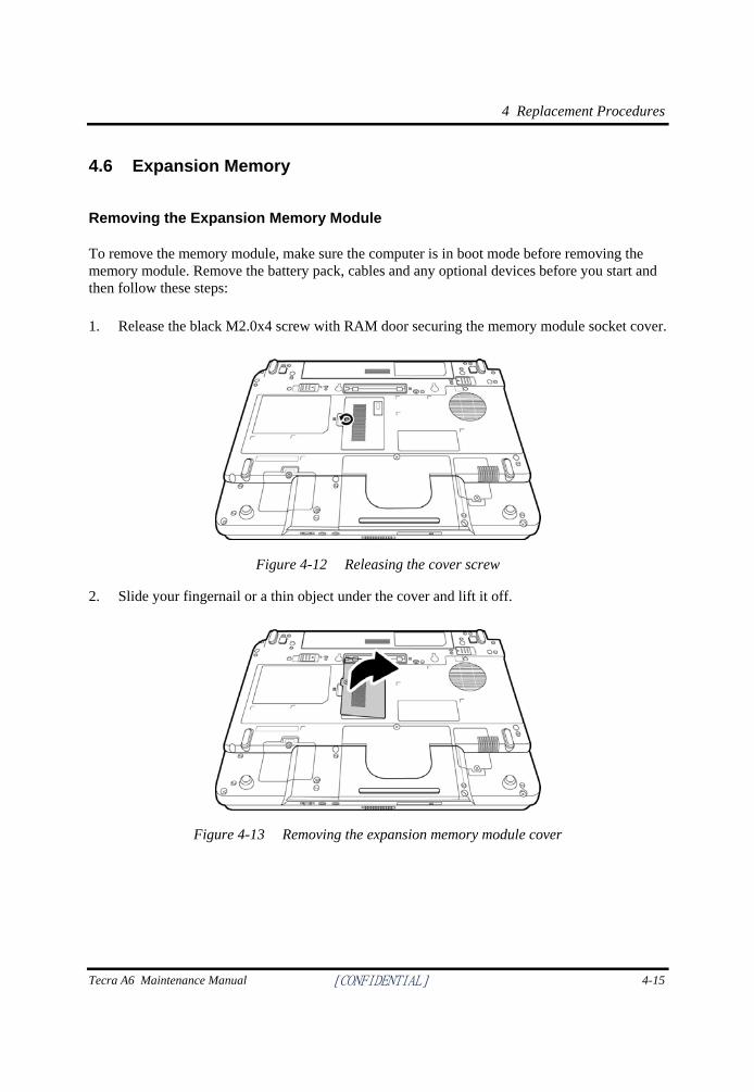
4 Replacement Procedures
Tecra A6 Maintenance Manual [CONFIDENTIAL] 4-15
4.6 Expansion Memory
Removing the Expansion Memory Module
To remove the memory module, make sure the computer is in boot mode before removing the memory module. Remove the battery pack, cables and any optional devices before you start and then follow these steps: 1. Release the black M2.0x4 screw with RAM door securing the memory module socket cover.
Figure 4-12 Releasing the cover screw
2. Slide your fingernail or a thin object under the cover and lift it off.
Figure 4-13 Removing the expansion memory module cover
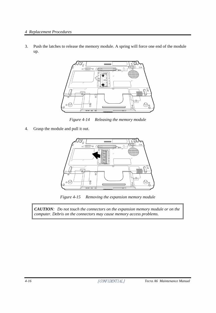
4 Replacement Procedures
4-16 [CONFIDENTIAL] Tecra A6 Maintenance Manual
3. Push the latches to release the memory module. A spring will force one end of the module up.
Figure 4-14 Releasing the memory module
4. Grasp the module and pull it out.
Figure 4-15 Removing the expansion memory module
CAUTION: Do not touch the connectors on the expansion memory module or on the computer. Debris on the connectors may cause memory access problems.
4 Replacement Procedures
Tecra A6 Maintenance Manual [CONFIDENTIAL] 4-17
Installing the Expansion Memory Module
CAUTION: Do not touch the connectors on the expansion memory module or on the computer. Debris on the connectors may cause memory access problems.
Follow these steps to install a memory module: 1. Set the computer to boot mode and turn off the power.
2. Remove the black Non separate Screw with RAM door M2.5x6.5 (Special Type) screw securing the memory module socket cover.
3. Slide your fingernail or a thin object under the cover and lift it off.
4. Fit the module's connectors into the computer's connectors at about a 45-degree angle and press the module carefully to ensure a firm connection.
5. Push the module down so it lies flat. The latches on either side will click into place to secure the module.
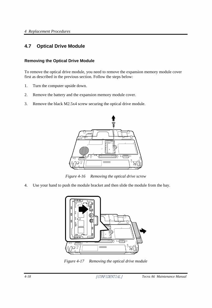
4 Replacement Procedures
4-18 [CONFIDENTIAL] Tecra A6 Maintenance Manual
4.7 Optical Drive Module
Removing the Optical Drive Module
To remove the optical drive module, you need to remove the expansion memory module cover first as described in the previous section. Follow the steps below:
1. Turn the computer upside down.
2. Remove the battery and the expansion memory module cover.
3. Remove the black M2.5x4 screw securing the optical drive module.
Figure 4-16 Removing the optical drive screw
4. Use your hand to push the module bracket and then slide the module from the bay.
Figure 4-17 Removing the optical drive module
4 Replacement Procedures
Tecra A6 Maintenance Manual [CONFIDENTIAL] 4-19
Installing the Optical Drive Module
To install a device in the optical drive module bay, follow the steps below and refer to the figure in the preceding section.
1. Make sure that the expansion memory door is opened and the ODD screw (M2.5x4, black) is removed.
2. Slide the device into the optical drive module bay.
3. Use the black M2.5x4 screw to secure the optical drive module.
4. Replace the expansion memory module cover.
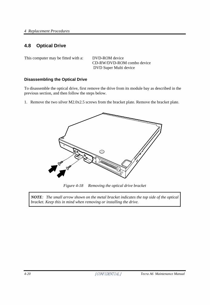
4 Replacement Procedures
4-20 [CONFIDENTIAL] Tecra A6 Maintenance Manual
4.8 Optical Drive
This computer may be fitted with a: DVD-ROM device CD-RW/DVD-ROM combo device DVD Super Multi device
Disassembling the Optical Drive
To disassemble the optical drive, first remove the drive from its module bay as described in the previous section, and then follow the steps below.
1. Remove the two silver M2.0x2.5 screws from the bracket plate. Remove the bracket plate.
Figure 4-18 Removing the optical drive bracket
NOTE: The small arrow shown on the metal bracket indicates the top side of the optical bracket. Keep this in mind when removing or installing the drive.
4 Replacement Procedures
Tecra A6 Maintenance Manual [CONFIDENTIAL] 4-21
Reassembling the Optical Drive
NOTE: The small arrow shown on the metal bracket indicates the top side of the optical bracket. Keep this in mind when removing or installing the drive.
To reassemble an optical drive, follow the steps below and refer to the figure in the preceding section.
1. Position the optical drive bracket plate so that it is aligned with the rear panel of optical drive.
2. Secure the optical drive bracket plate with silver M2.0×2.5 screws.
3. Install the optical drive module into the bay as described in the preceding section.
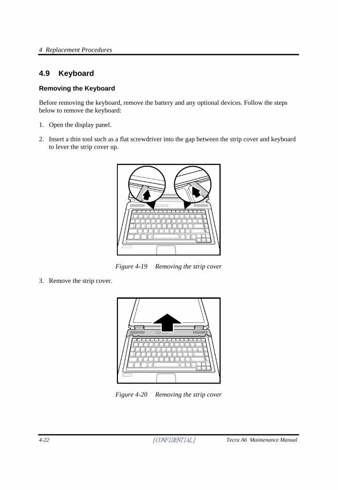
4 Replacement Procedures
4-22 [CONFIDENTIAL] Tecra A6 Maintenance Manual
4.9 Keyboard
Removing the Keyboard
Before removing the keyboard, remove the battery and any optional devices. Follow the steps below to remove the keyboard:
1. Open the display panel.
2. Insert a thin tool such as a flat screwdriver into the gap between the strip cover and keyboard to lever the strip cover up.
Figure 4-19 Removing the strip cover
3. Remove the strip cover.
Figure 4-20 Removing the strip cover
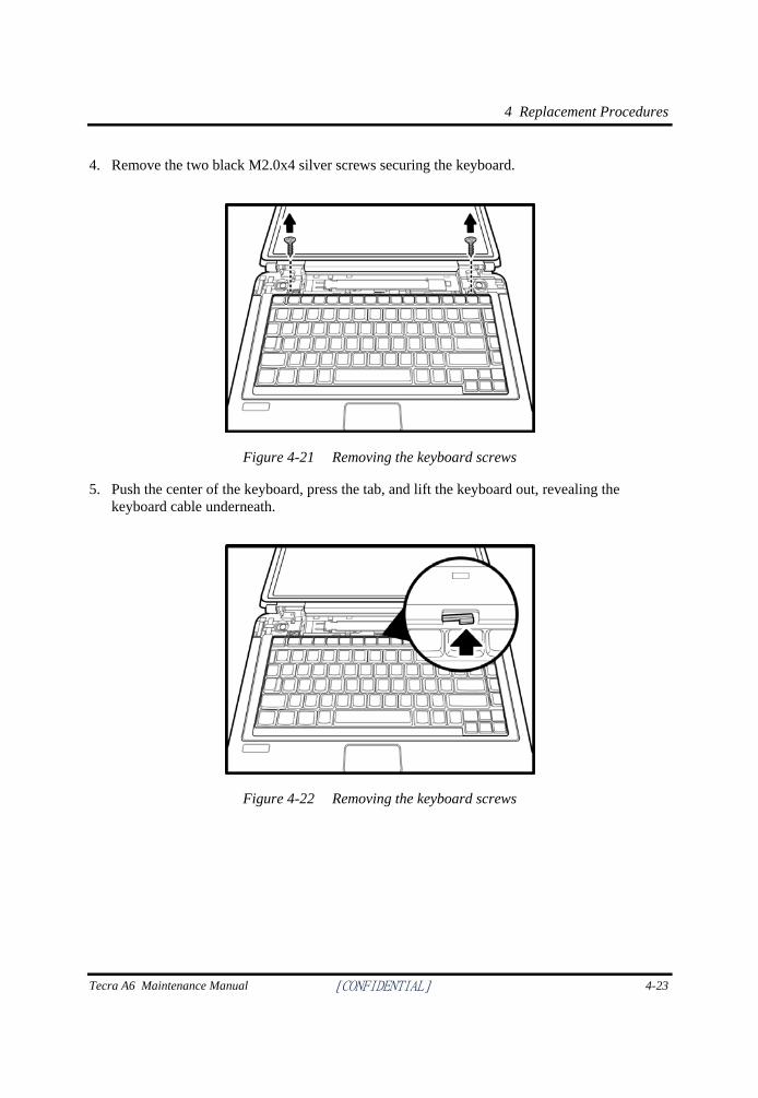
4 Replacement Procedures
Tecra A6 Maintenance Manual [CONFIDENTIAL] 4-23
4. Remove the two black M2.0x4 silver screws securing the keyboard.
Figure 4-21 Removing the keyboard screws
5. Push the center of the keyboard, press the tab, and lift the keyboard out, revealing the keyboard cable underneath.
Figure 4-22 Removing the keyboard screws
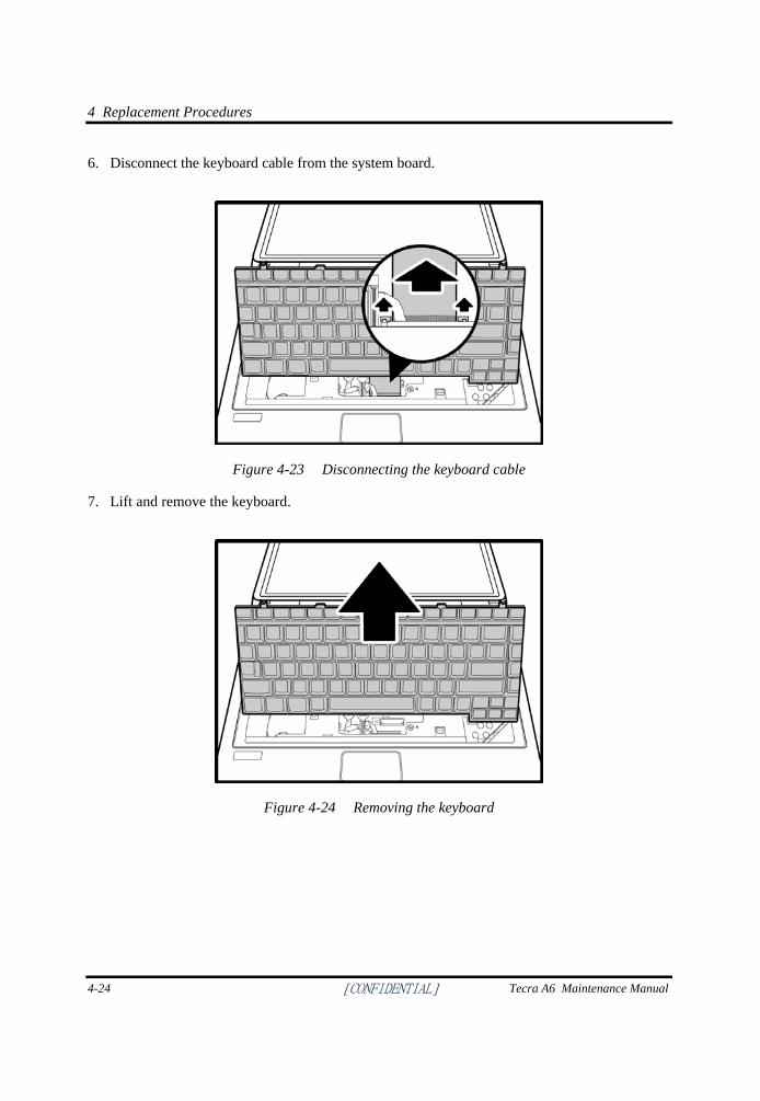
4 Replacement Procedures
4-24 [CONFIDENTIAL] Tecra A6 Maintenance Manual
6. Disconnect the keyboard cable from the system board.
Figure 4-23 Disconnecting the keyboard cable
7. Lift and remove the keyboard.
Figure 4-24 Removing the keyboard
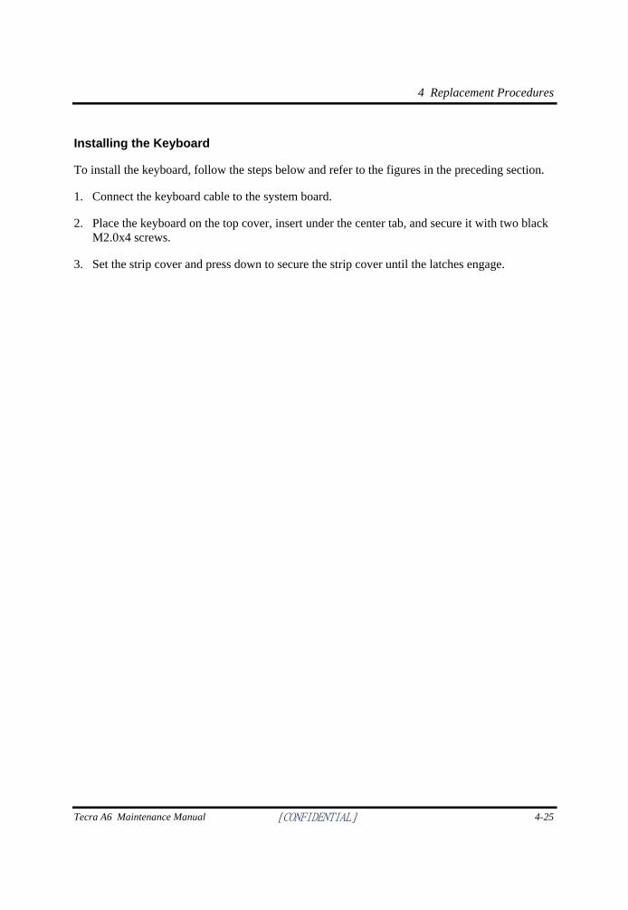
4 Replacement Procedures
Tecra A6 Maintenance Manual [CONFIDENTIAL] 4-25
Installing the Keyboard
To install the keyboard, follow the steps below and refer to the figures in the preceding section.
1. Connect the keyboard cable to the system board.
2. Place the keyboard on the top cover, insert under the center tab, and secure it with two black M2.0x4 screws.
3. Set the strip cover and press down to secure the strip cover until the latches engage.
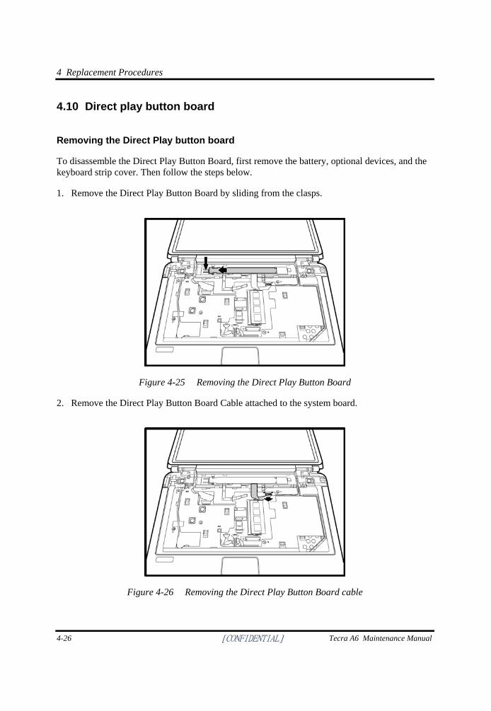
4 Replacement Procedures
4-26 [CONFIDENTIAL] Tecra A6 Maintenance Manual
4.10 Direct play button board
Removing the Direct Play button board
To disassemble the Direct Play Button Board, first remove the battery, optional devices, and the keyboard strip cover. Then follow the steps below.
1. Remove the Direct Play Button Board by sliding from the clasps.
Figure 4-25 Removing the Direct Play Button Board
2. Remove the Direct Play Button Board Cable attached to the system board.
Figure 4-26 Removing the Direct Play Button Board cable
4 Replacement Procedures
Tecra A6 Maintenance Manual [CONFIDENTIAL] 4-27
Installing the Direct Play Button Board
To install the Direct Play Button Board, follow the steps below and refer to the figures in the preceding section.
1. Connect the cable to the connector on the system board.
2. Install the Direct Play Button Board in place while securing the clasps.
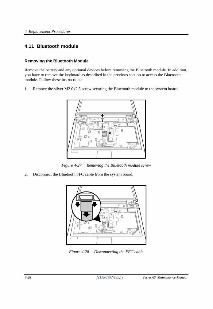
4 Replacement Procedures
4-28 [CONFIDENTIAL] Tecra A6 Maintenance Manual
4.11 Bluetooth module
Removing the Bluetooth Module
Remove the battery and any optional devices before removing the Bluetooth module. In addition, you have to remove the keyboard as described in the previous section to access the Bluetooth module. Follow these instructions:
1. Remove the silver M2.0x2.5 screw securing the Bluetooth module to the system board.
Figure 4-27 Removing the Bluetooth module screw
2. Disconnect the Bluetooth FFC cable from the system board.
Figure 4-28 Disconnecting the FFC cable
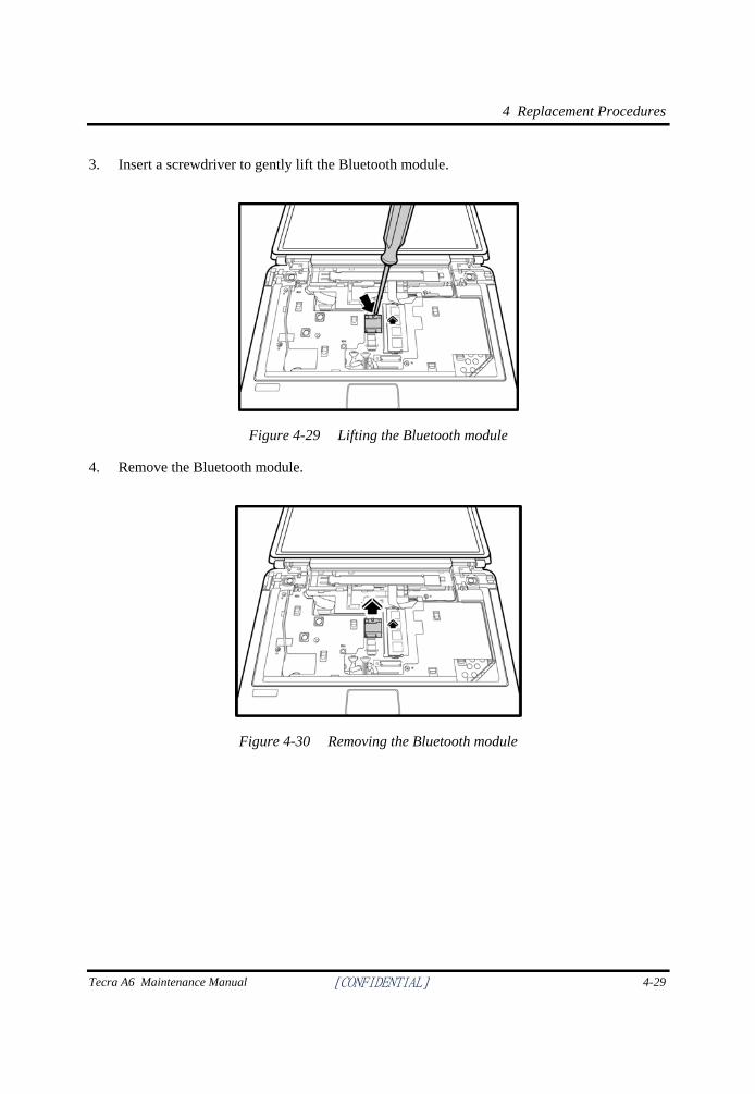
4 Replacement Procedures
Tecra A6 Maintenance Manual [CONFIDENTIAL] 4-29
3. Insert a screwdriver to gently lift the Bluetooth module.
Figure 4-29 Lifting the Bluetooth module
4. Remove the Bluetooth module.
Figure 4-30 Removing the Bluetooth module
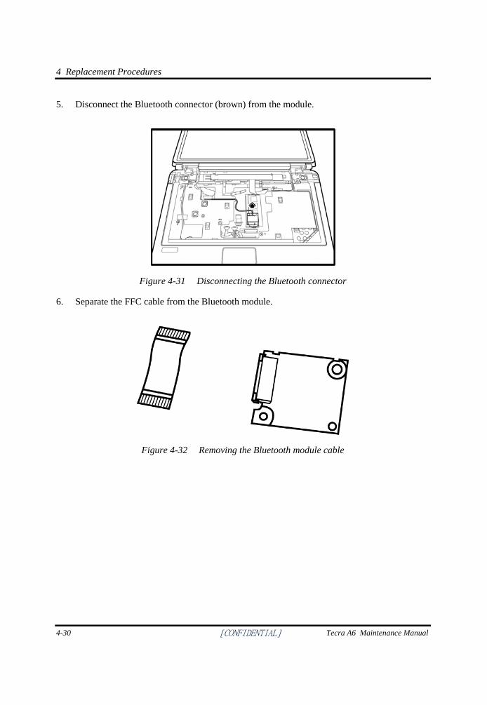
4 Replacement Procedures
4-30 [CONFIDENTIAL] Tecra A6 Maintenance Manual
5. Disconnect the Bluetooth connector (brown) from the module.
Figure 4-31 Disconnecting the Bluetooth connector
6. Separate the FFC cable from the Bluetooth module.
Figure 4-32 Removing the Bluetooth module cable
4 Replacement Procedures
Tecra A6 Maintenance Manual [CONFIDENTIAL] 4-31
Installing the Bluetooth Module
To install the Bluetooth module, follow the steps below and refer to the figures in the preceding section.
1. Secure the module to the system board using one silver M2.0x2.5 screw.
2. Connect the FFC cable to the module to connect to the system board.
3. Connect the Bluetooth connector (brown) to the module.
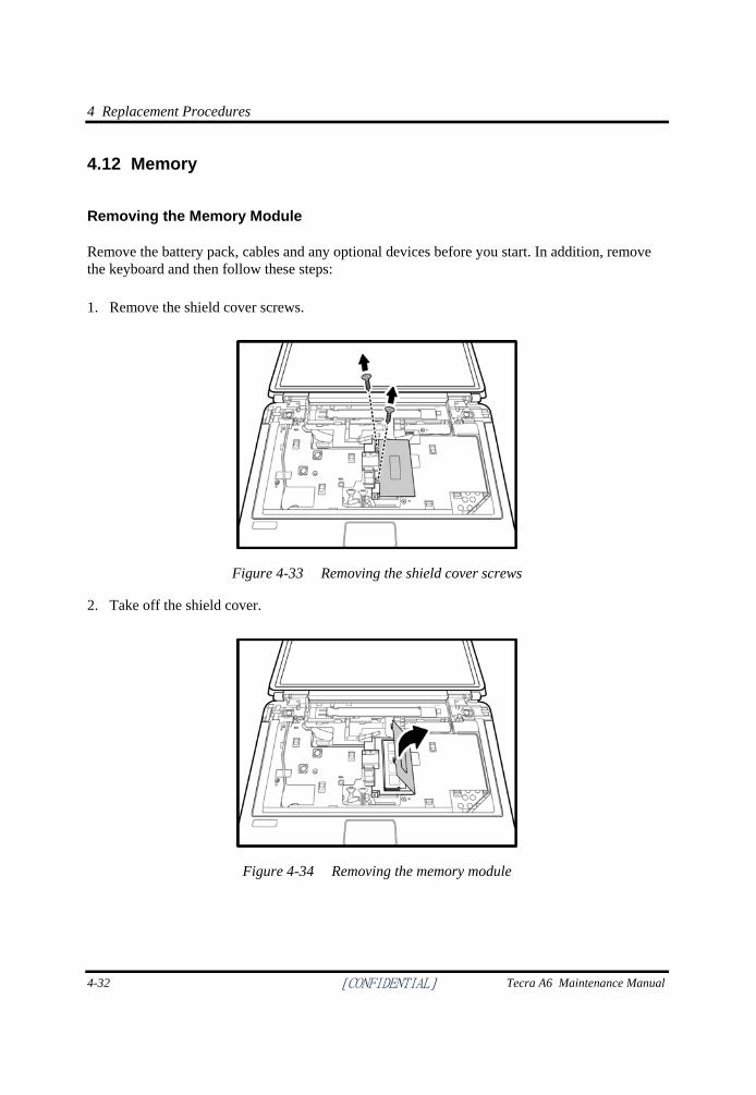
4 Replacement Procedures
4-32 [CONFIDENTIAL] Tecra A6 Maintenance Manual
4.12 Memory
Removing the Memory Module
Remove the battery pack, cables and any optional devices before you start. In addition, remove the keyboard and then follow these steps: 1. Remove the shield cover screws.
Figure 4-33 Removing the shield cover screws
2. Take off the shield cover.
Figure 4-34 Removing the memory module
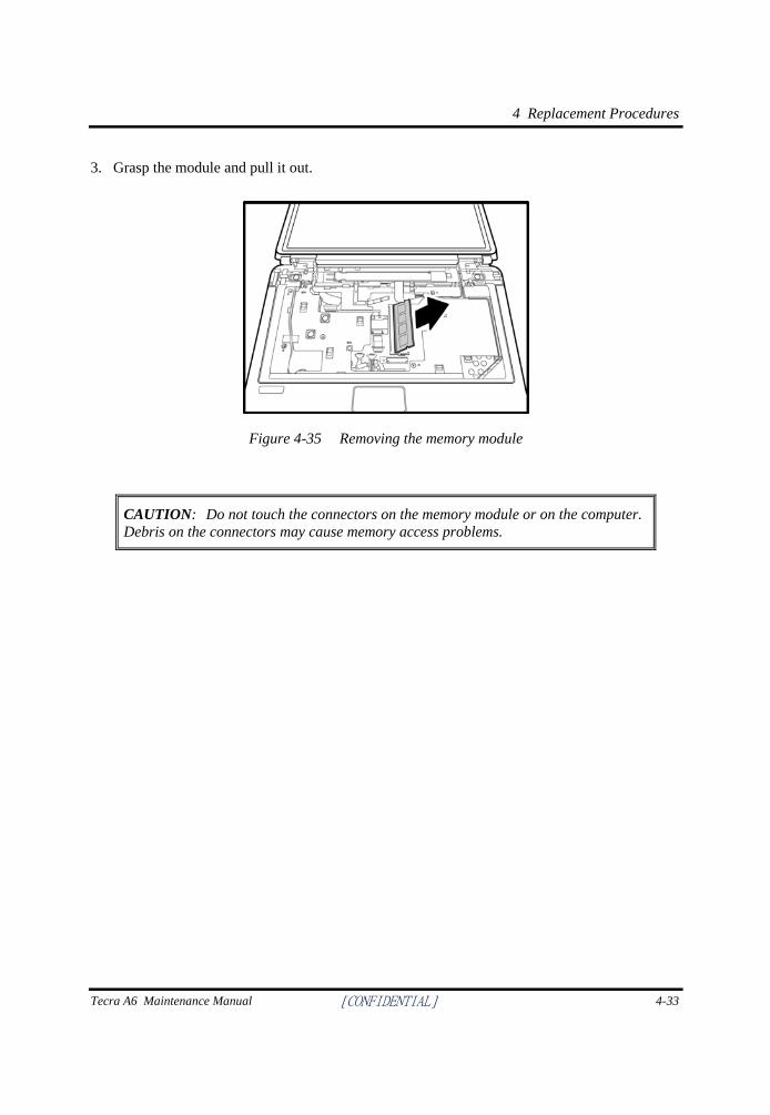
4 Replacement Procedures
Tecra A6 Maintenance Manual [CONFIDENTIAL] 4-33
3. Grasp the module and pull it out.
Figure 4-35 Removing the memory module
CAUTION: Do not touch the connectors on the memory module or on the computer. Debris on the connectors may cause memory access problems.
4 Replacement Procedures
4-34 [CONFIDENTIAL] Tecra A6 Maintenance Manual
Installing the Expansion Memory Module
CAUTION: Do not touch the connectors on the memory module or on the computer. Debris on the connectors may cause memory access problems.
Follow these steps to install a memory module, while referring to the illustrations on the previous page: 1. Fit the module's connectors into the computer's connectors at about a 45-degree angle and
press the module carefully to ensure a firm connection.
2. Push the module down so it lies flat.
3. Place the shield cover about a 45-degree angle and push it down so it lies flat on the top of the module.
4. Secure the shield cover with screws.
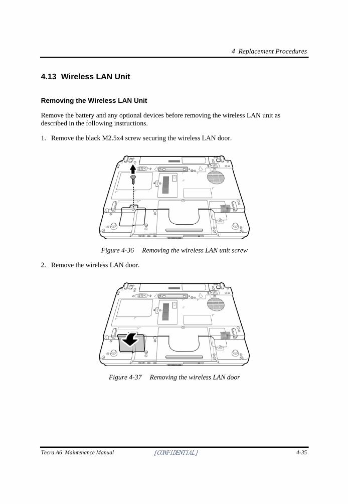
4 Replacement Procedures
Tecra A6 Maintenance Manual [CONFIDENTIAL] 4-35
4.13 Wireless LAN Unit
Removing the Wireless LAN Unit
Remove the battery and any optional devices before removing the wireless LAN unit as described in the following instructions.
1. Remove the black M2.5x4 screw securing the wireless LAN door.
Figure 4-36 Removing the wireless LAN unit screw
2. Remove the wireless LAN door.
Figure 4-37 Removing the wireless LAN door
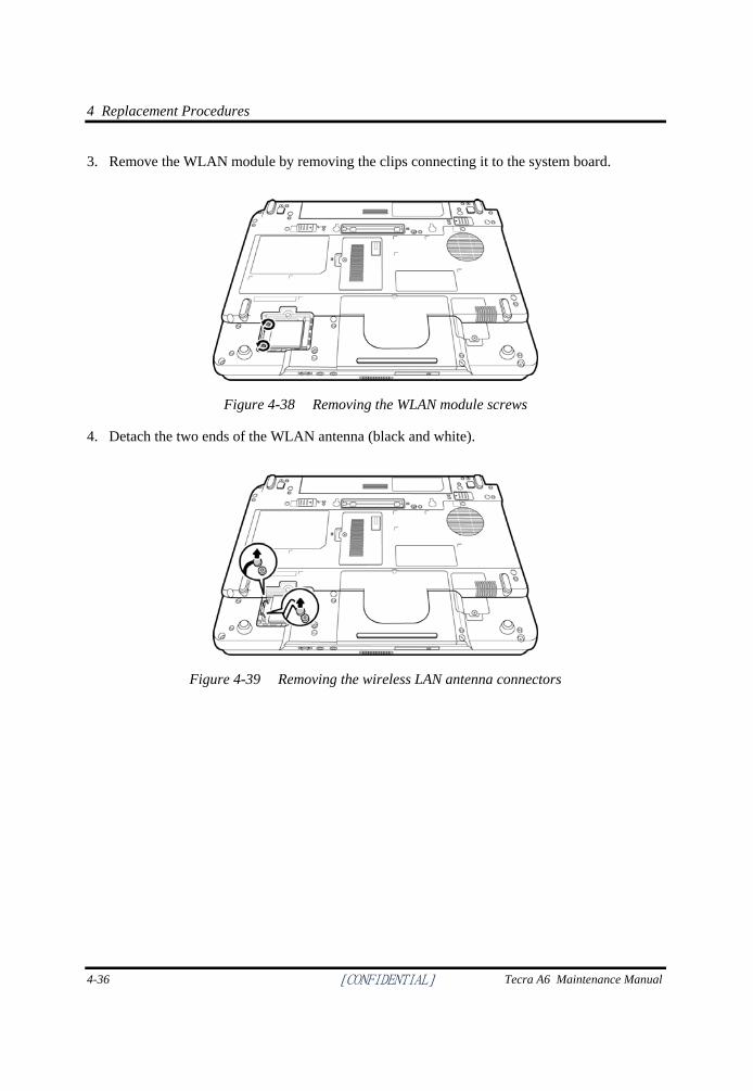
4 Replacement Procedures
4-36 [CONFIDENTIAL] Tecra A6 Maintenance Manual
3. Remove the WLAN module by removing the clips connecting it to the system board.
Figure 4-38 Removing the WLAN module screws
4. Detach the two ends of the WLAN antenna (black and white).
Figure 4-39 Removing the wireless LAN antenna connectors
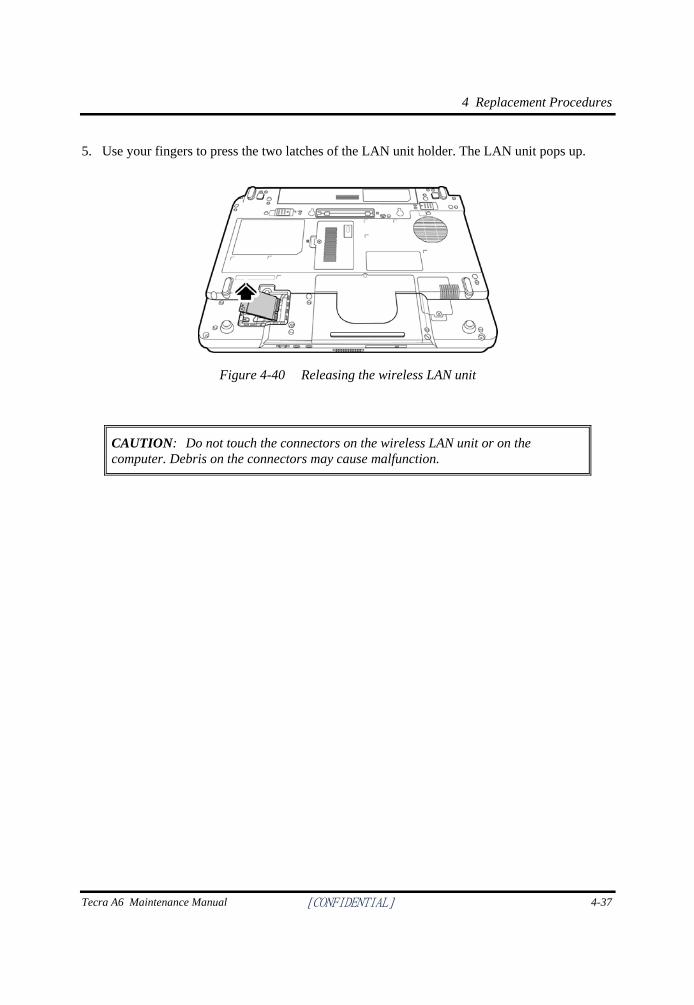
4 Replacement Procedures
Tecra A6 Maintenance Manual [CONFIDENTIAL] 4-37
5. Use your fingers to press the two latches of the LAN unit holder. The LAN unit pops up.
Figure 4-40 Releasing the wireless LAN unit
CAUTION: Do not touch the connectors on the wireless LAN unit or on the computer. Debris on the connectors may cause malfunction.
4 Replacement Procedures
4-38 [CONFIDENTIAL] Tecra A6 Maintenance Manual
Installing the Wireless LAN Unit
To install the wireless LAN unit, follow the steps below and refer to the figures in the preceding section.
1. Remove the black M2.5x3 screw securing the wireless LAN door, and then remove the wireless LAN door as described previously.
CAUTION: Do not touch the connectors on the wireless LAN unit or on the computer. Debris on the connectors may cause malfunction.
2. Place the wireless LAN unit in the wireless LAN holder and gently press down. The two latches of the holder will snap close to hold the unit.
3. Attach the white antenna to the main connector, and the black antenna to the Aux connector.
4. Use the black M2.5x4 screw to secure the wireless LAN door.
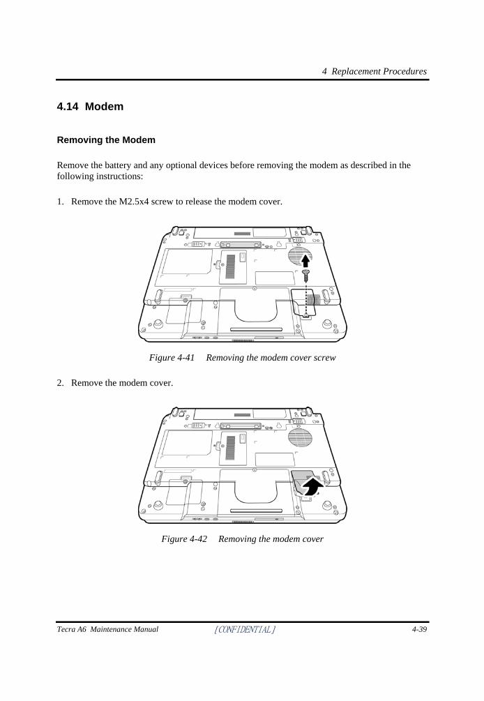
4 Replacement Procedures
Tecra A6 Maintenance Manual [CONFIDENTIAL] 4-39
4.14 Modem
Removing the Modem
Remove the battery and any optional devices before removing the modem as described in the following instructions:
1. Remove the M2.5x4 screw to release the modem cover.
Figure 4-41 Removing the modem cover screw
2. Remove the modem cover.
Figure 4-42 Removing the modem cover
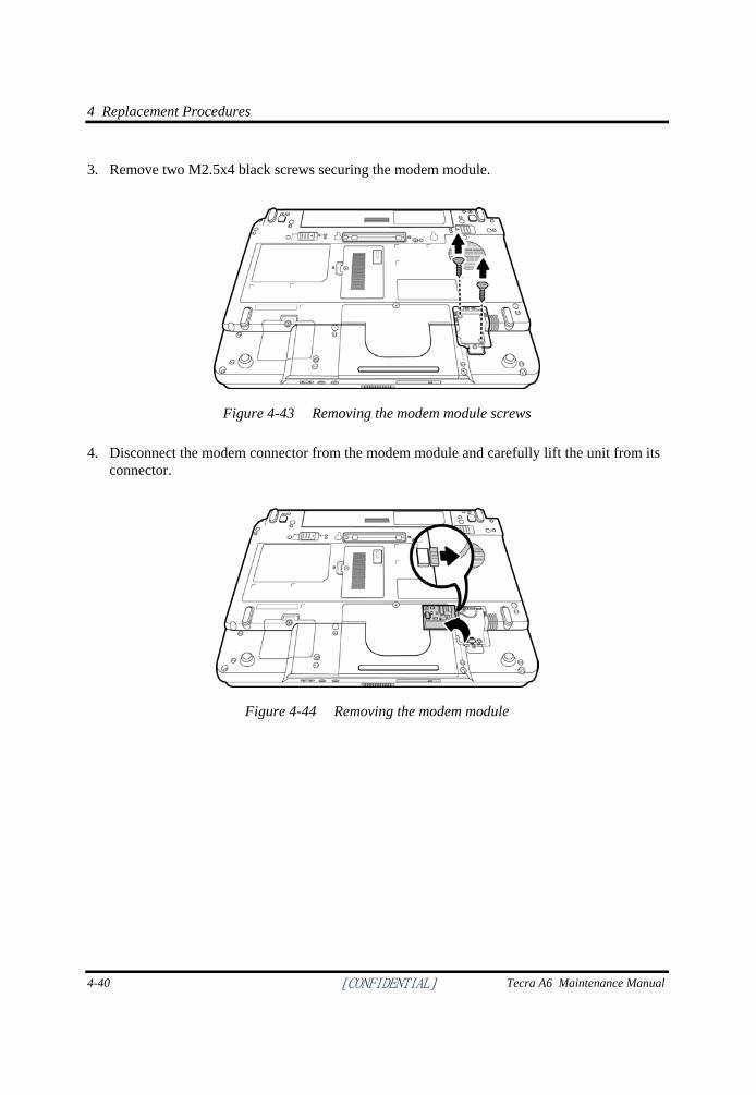
4 Replacement Procedures
4-40 [CONFIDENTIAL] Tecra A6 Maintenance Manual
3. Remove two M2.5x4 black screws securing the modem module.
Figure 4-43 Removing the modem module screws
4. Disconnect the modem connector from the modem module and carefully lift the unit from its connector.
Figure 4-44 Removing the modem module
4 Replacement Procedures
Tecra A6 Maintenance Manual [CONFIDENTIAL] 4-41
Installing the Modem
To install a modem, follow the steps below and refer to the figures in the preceding section.
1. Connect the modem connector on the system board to the modem module.
2. Fit the modem onto its connector and secure it with two black M2.5x4 screws.
3. Replace the M2.5x4 screw to fix the modem cover.
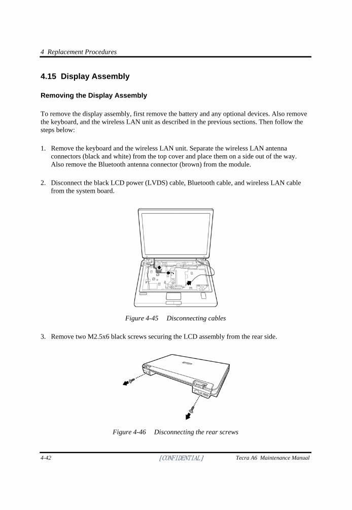
4 Replacement Procedures
4-42 [CONFIDENTIAL] Tecra A6 Maintenance Manual
4.15 Display Assembly
Removing the Display Assembly
To remove the display assembly, first remove the battery and any optional devices. Also remove the keyboard, and the wireless LAN unit as described in the previous sections. Then follow the steps below:
1. Remove the keyboard and the wireless LAN unit. Separate the wireless LAN antenna connectors (black and white) from the top cover and place them on a side out of the way. Also remove the Bluetooth antenna connector (brown) from the module.
2. Disconnect the black LCD power (LVDS) cable, Bluetooth cable, and wireless LAN cable from the system board.
Figure 4-45 Disconnecting cables
3. Remove two M2.5x6 black screws securing the LCD assembly from the rear side.
Figure 4-46 Disconnecting the rear screws
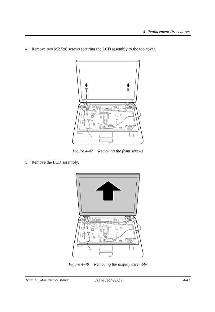
4 Replacement Procedures
Tecra A6 Maintenance Manual [CONFIDENTIAL] 4-43
4. Remove two M2.5x6 screws securing the LCD assembly to the top cover.
Figure 4-47 Removing the front screws
5. Remove the LCD assembly.
Figure 4-48 Removing the display assembly
4 Replacement Procedures
4-44 [CONFIDENTIAL] Tecra A6 Maintenance Manual
Installing the Display Assembly
To install the display assembly, follow the steps below and refer to the figures in the preceding section.
1. Seat the display assembly, taking care not to crush to the LCD display cable, the LCD power cable, the wireless LAN antenna connectors, or the Bluetooth connector.
2. Secure two M2.5x6 black screws to each hinge to connect the assembly to the top cover.
3. Secure two black M2.5x6 black screws to the computer’s rear side. They hold the display assembly in place.
4. Feed the wireless LAN module’s antennae wires through the indented track on the system board towards the rear side.
5. Connect the Bluetooth connector to the Bluetooth module.
6. Connect the LCD power cable to the top chassis.
7. Reinstall the keyboard and wireless LAN module.
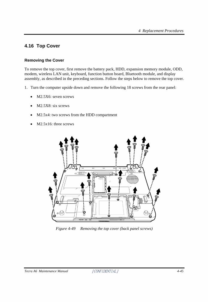
4 Replacement Procedures
Tecra A6 Maintenance Manual [CONFIDENTIAL] 4-45
4.16 Top Cover
Removing the Cover
To remove the top cover, first remove the battery pack, HDD, expansion memory module, ODD, modem, wireless LAN unit, keyboard, function button board, Bluetooth module, and display assembly, as described in the preceding sections. Follow the steps below to remove the top cover.
1. Turn the computer upside down and remove the following 18 screws from the rear panel:
• M2.5X6: seven screws
• M2.5X8: six screws
• M2.5x4: two screws from the HDD compartment
• M2.5x16: three screws
Figure 4-49 Removing the top cover (back panel screws)
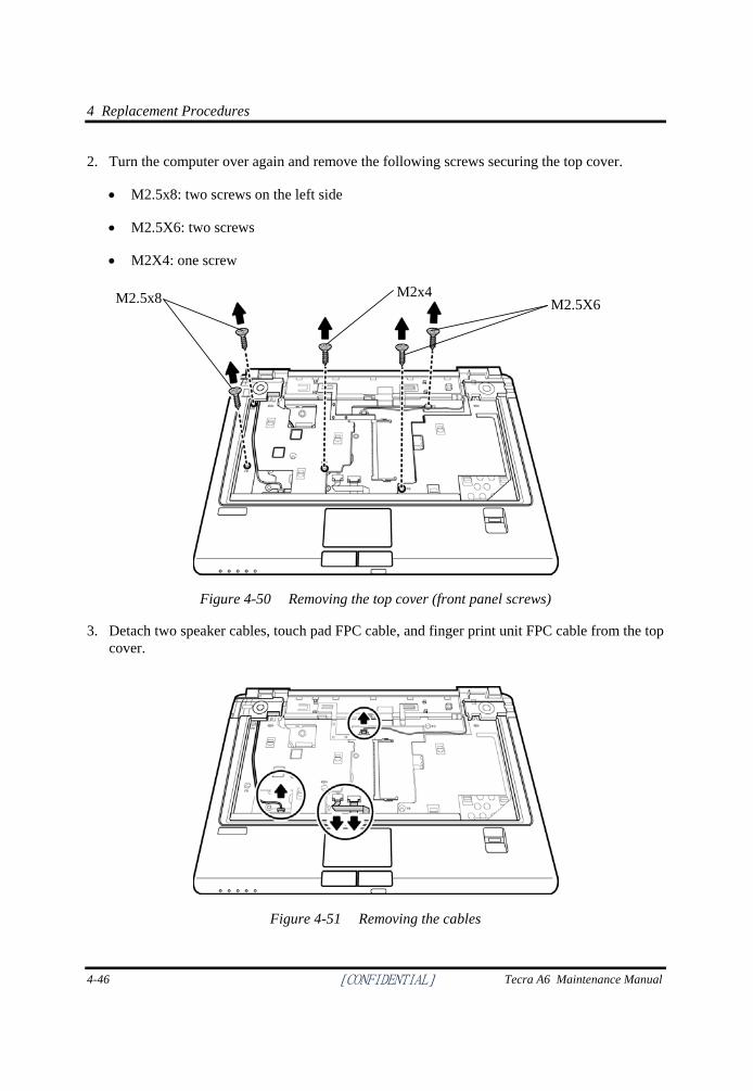
4 Replacement Procedures
4-46 [CONFIDENTIAL] Tecra A6 Maintenance Manual
2. Turn the computer over again and remove the following screws securing the top cover.
• M2.5x8: two screws on the left side
• M2.5X6: two screws
• M2X4: one screw
Figure 4-50 Removing the top cover (front panel screws)
3. Detach two speaker cables, touch pad FPC cable, and finger print unit FPC cable from the top cover.
Figure 4-51 Removing the cables
M2.5x8 M2x4 M2.5X6
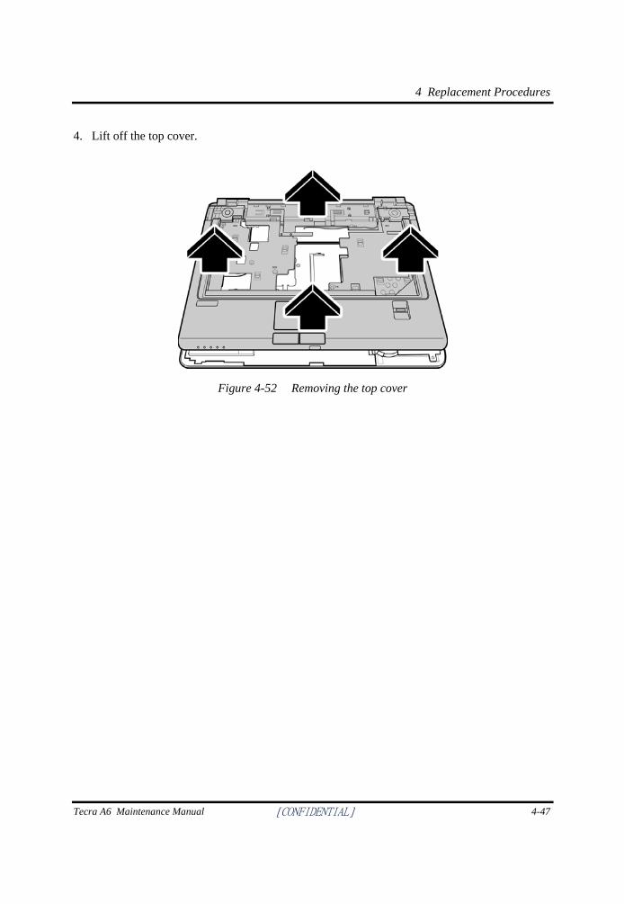
4 Replacement Procedures
Tecra A6 Maintenance Manual [CONFIDENTIAL] 4-47
4. Lift off the top cover.
Figure 4-52 Removing the top cover
4 Replacement Procedures
4-48 [CONFIDENTIAL] Tecra A6 Maintenance Manual
Installing the Top Cover
To install the top cover, follow the steps below and refer to the figures in the preceding section.
1. Seat the top cover, and secure the speaker cables, finger print unit FFC cable, and touch pad unit FFC cable to the system board.
2. Secure the top cover with two M2.5x6 screws, two M2.5x8 screws, and one M2x4 screw.
3. Turn the computer upside down and secure the 18 screws to the rear panel.
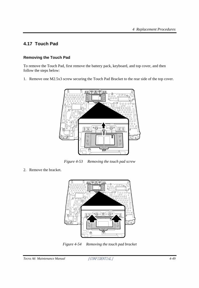
4 Replacement Procedures
Tecra A6 Maintenance Manual [CONFIDENTIAL] 4-49
4.17 Touch Pad
Removing the Touch Pad
To remove the Touch Pad, first remove the battery pack, keyboard, and top cover, and then follow the steps below:
1. Remove one M2.5x3 screw securing the Touch Pad Bracket to the rear side of the top cover.
Figure 4-53 Removing the touch pad screw
2. Remove the bracket.
Figure 4-54 Removing the touch pad bracket
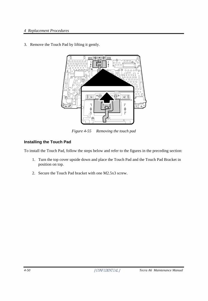
4 Replacement Procedures
4-50 [CONFIDENTIAL] Tecra A6 Maintenance Manual
3. Remove the Touch Pad by lifting it gently.
Figure 4-55 Removing the touch pad
Installing the Touch Pad
To install the Touch Pad, follow the steps below and refer to the figures in the preceding section:
1. Turn the top cover upside down and place the Touch Pad and the Touch Pad Bracket in position on top.
2. Secure the Touch Pad bracket with one M2.5x3 screw.
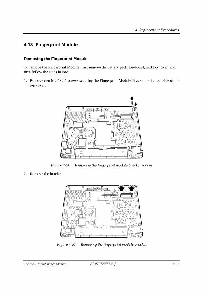
4 Replacement Procedures
Tecra A6 Maintenance Manual [CONFIDENTIAL] 4-51
4.18 Fingerprint Module
Removing the Fingerprint Module
To remove the Fingerprint Module, first remove the battery pack, keyboard, and top cover, and then follow the steps below:
1. Remove two M2.5x2.5 screws securing the Fingerprint Module Bracket to the rear side of the top cover.
Figure 4-56 Removing the fingerprint module bracket screws
2. Remove the bracket.
Figure 4-57 Removing the fingerprint module bracket
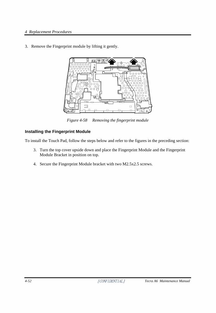
4 Replacement Procedures
4-52 [CONFIDENTIAL] Tecra A6 Maintenance Manual
3. Remove the Fingerprint module by lifting it gently.
Figure 4-58 Removing the fingerprint module
Installing the Fingerprint Module
To install the Touch Pad, follow the steps below and refer to the figures in the preceding section:
3. Turn the top cover upside down and place the Fingerprint Module and the Fingerprint Module Bracket in position on top.
4. Secure the Fingerprint Module bracket with two M2.5x2.5 screws.
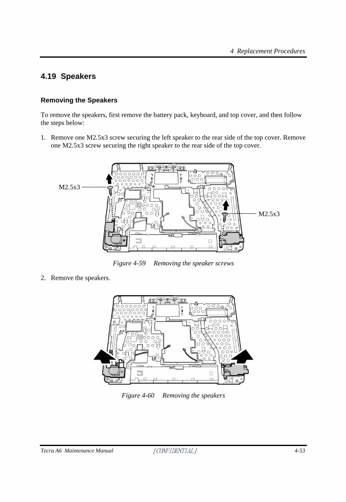
4 Replacement Procedures
Tecra A6 Maintenance Manual [CONFIDENTIAL] 4-53
4.19 Speakers
Removing the Speakers
To remove the speakers, first remove the battery pack, keyboard, and top cover, and then follow the steps below:
1. Remove one M2.5x3 screw securing the left speaker to the rear side of the top cover. Remove one M2.5x3 screw securing the right speaker to the rear side of the top cover.
Figure 4-59 Removing the speaker screws
2. Remove the speakers.
Figure 4-60 Removing the speakers
M2.5x3
M2.5x3
4 Replacement Procedures
4-54 [CONFIDENTIAL] Tecra A6 Maintenance Manual
Installing the Speakers
To install the speakers, follow the steps below and refer to the figures in the preceding section:
1. Turn the top cover upside down and place the speakers in position on top.
2. Secure the speakers with two M2.5x3 screws.
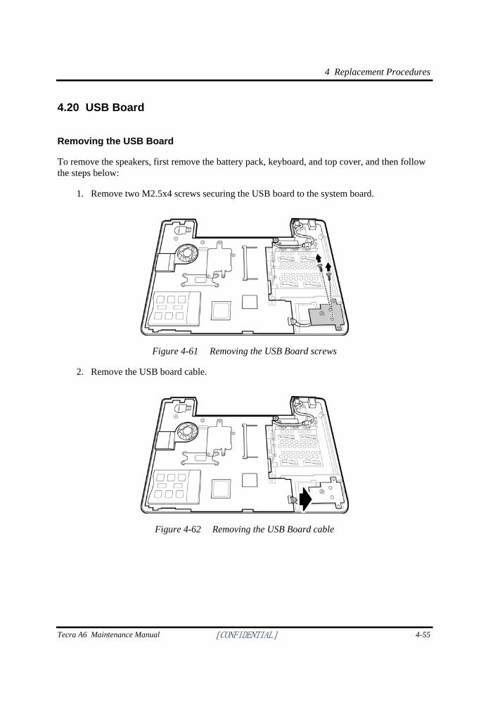
4 Replacement Procedures
Tecra A6 Maintenance Manual [CONFIDENTIAL] 4-55
4.20 USB Board
Removing the USB Board
To remove the speakers, first remove the battery pack, keyboard, and top cover, and then follow the steps below:
1. Remove two M2.5x4 screws securing the USB board to the system board.
Figure 4-61 Removing the USB Board screws
2. Remove the USB board cable.
Figure 4-62 Removing the USB Board cable
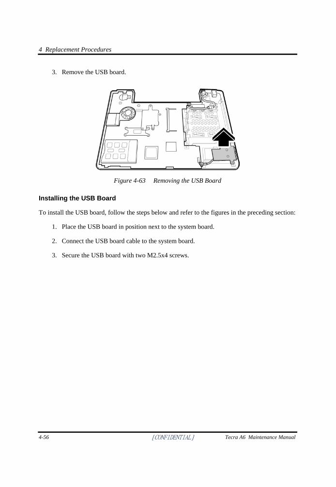
4 Replacement Procedures
4-56 [CONFIDENTIAL] Tecra A6 Maintenance Manual
3. Remove the USB board.
Figure 4-63 Removing the USB Board
Installing the USB Board
To install the USB board, follow the steps below and refer to the figures in the preceding section:
1. Place the USB board in position next to the system board.
2. Connect the USB board cable to the system board.
3. Secure the USB board with two M2.5x4 screws.
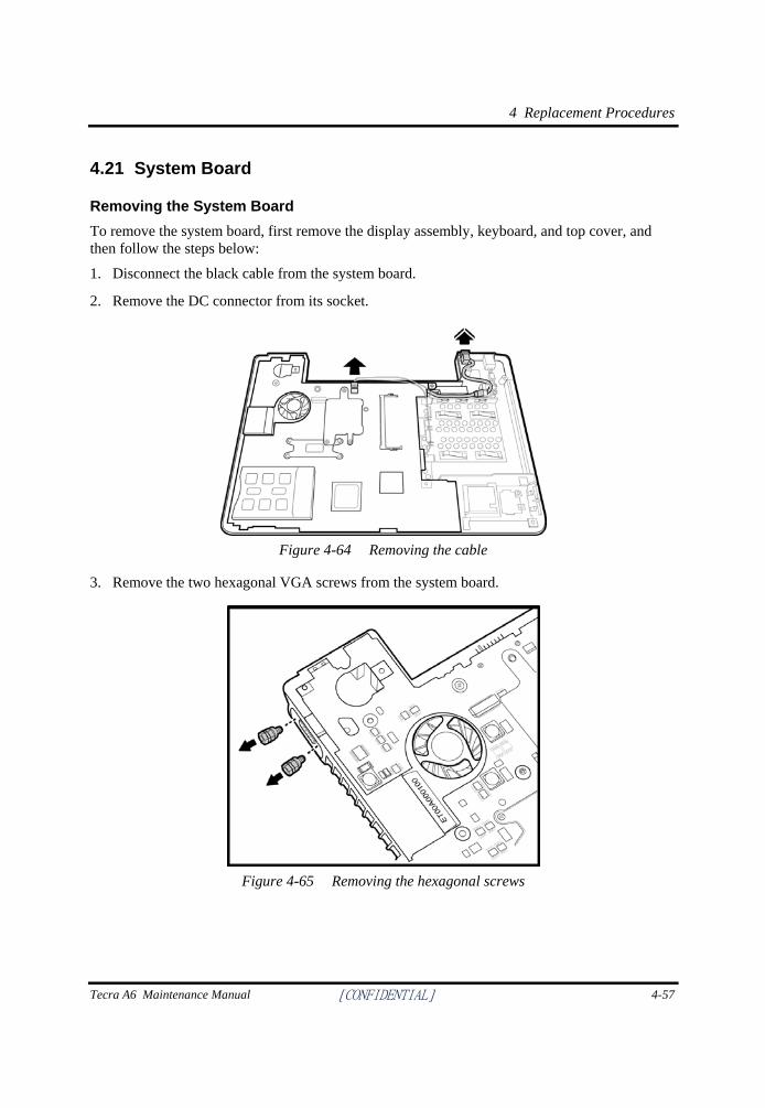
4 Replacement Procedures
Tecra A6 Maintenance Manual [CONFIDENTIAL] 4-57
4.21 System Board
Removing the System Board To remove the system board, first remove the display assembly, keyboard, and top cover, and then follow the steps below:
1. Disconnect the black cable from the system board.
2. Remove the DC connector from its socket.
Figure 4-64 Removing the cable
3. Remove the two hexagonal VGA screws from the system board.
Figure 4-65 Removing the hexagonal screws
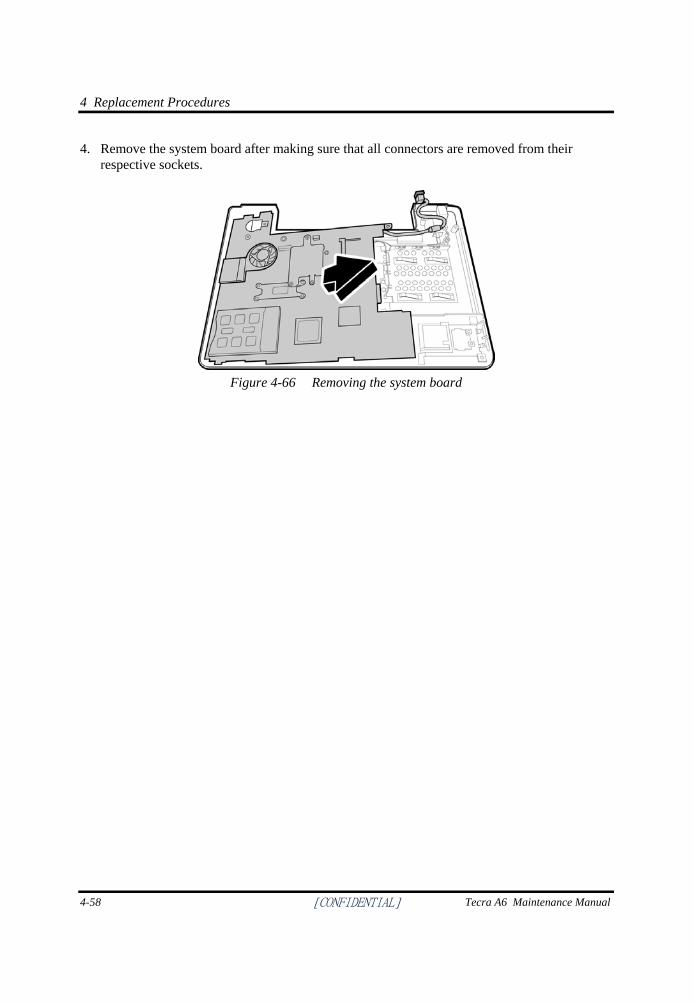
4 Replacement Procedures
4-58 [CONFIDENTIAL] Tecra A6 Maintenance Manual
4. Remove the system board after making sure that all connectors are removed from their respective sockets.
Figure 4-66 Removing the system board
4 Replacement Procedures
Tecra A6 Maintenance Manual [CONFIDENTIAL] 4-59
Installing the System Board
To install the system board, follow the steps below and refer to the figures in the preceding section.
1. Seat the system board in the chassis. Take care to align all the ports and connectors in their respective openings on the chassis.
2. Replace the two hexagonal screws to secure the VGA port.
3. Connect the black cable to its connector.
4. Connect the power connector in its socket.
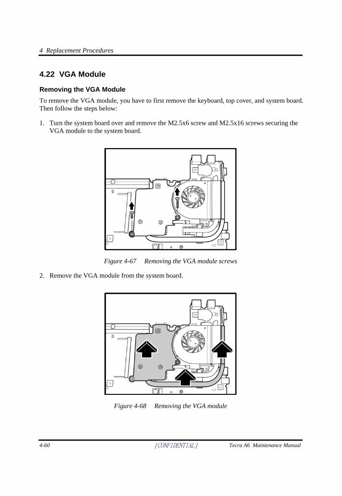
4 Replacement Procedures
4-60 [CONFIDENTIAL] Tecra A6 Maintenance Manual
4.22 VGA Module
Removing the VGA Module To remove the VGA module, you have to first remove the keyboard, top cover, and system board. Then follow the steps below:
1. Turn the system board over and remove the M2.5x6 screw and M2.5x16 screws securing the VGA module to the system board.
Figure 4-67 Removing the VGA module screws
2. Remove the VGA module from the system board.
Figure 4-68 Removing the VGA module
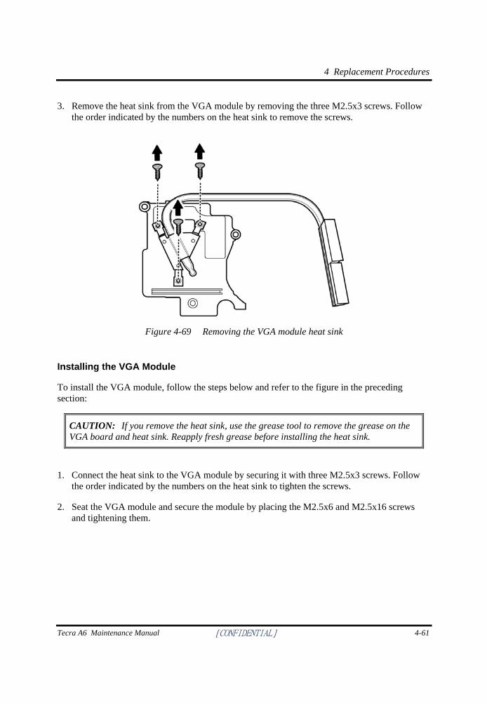
4 Replacement Procedures
Tecra A6 Maintenance Manual [CONFIDENTIAL] 4-61
3. Remove the heat sink from the VGA module by removing the three M2.5x3 screws. Follow the order indicated by the numbers on the heat sink to remove the screws.
Figure 4-69 Removing the VGA module heat sink
Installing the VGA Module
To install the VGA module, follow the steps below and refer to the figure in the preceding section:
CAUTION: If you remove the heat sink, use the grease tool to remove the grease on the VGA board and heat sink. Reapply fresh grease before installing the heat sink.
1. Connect the heat sink to the VGA module by securing it with three M2.5x3 screws. Follow the order indicated by the numbers on the heat sink to tighten the screws.
2. Seat the VGA module and secure the module by placing the M2.5x6 and M2.5x16 screws and tightening them.
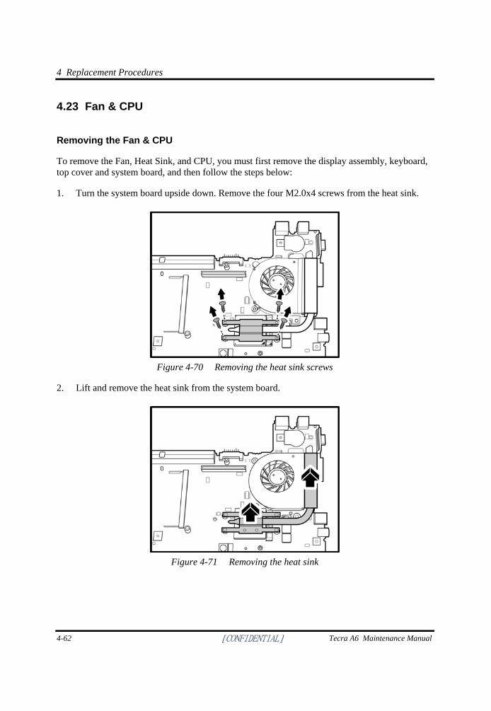
4 Replacement Procedures
4-62 [CONFIDENTIAL] Tecra A6 Maintenance Manual
4.23 Fan & CPU
Removing the Fan & CPU
To remove the Fan, Heat Sink, and CPU, you must first remove the display assembly, keyboard, top cover and system board, and then follow the steps below:
1. Turn the system board upside down. Remove the four M2.0x4 screws from the heat sink.
Figure 4-70 Removing the heat sink screws
2. Lift and remove the heat sink from the system board.
Figure 4-71 Removing the heat sink
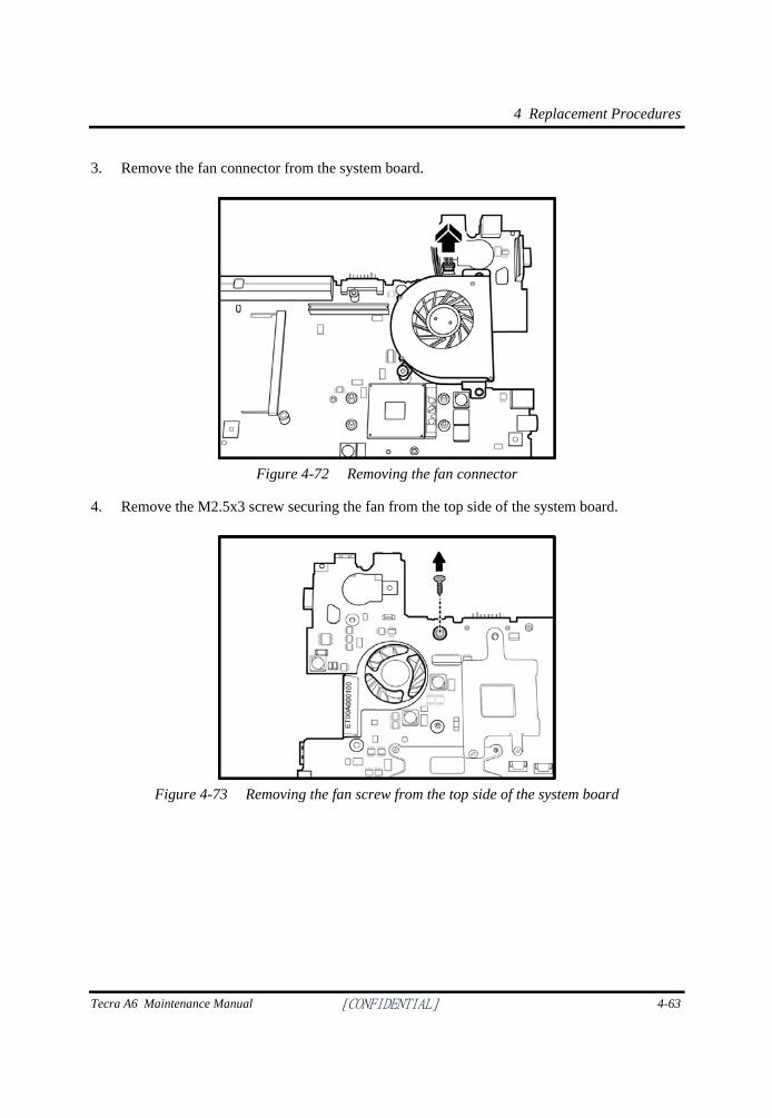
4 Replacement Procedures
Tecra A6 Maintenance Manual [CONFIDENTIAL] 4-63
3. Remove the fan connector from the system board.
Figure 4-72 Removing the fan connector
4. Remove the M2.5x3 screw securing the fan from the top side of the system board.
Figure 4-73 Removing the fan screw from the top side of the system board
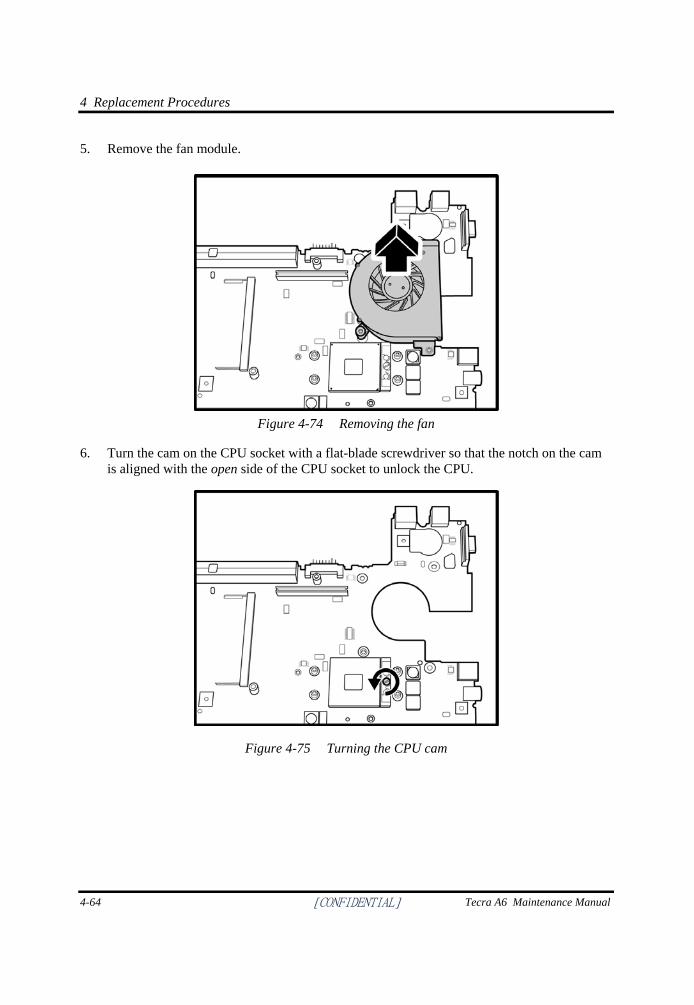
4 Replacement Procedures
4-64 [CONFIDENTIAL] Tecra A6 Maintenance Manual
5. Remove the fan module.
Figure 4-74 Removing the fan
6. Turn the cam on the CPU socket with a flat-blade screwdriver so that the notch on the cam is aligned with the open side of the CPU socket to unlock the CPU.
Figure 4-75 Turning the CPU cam
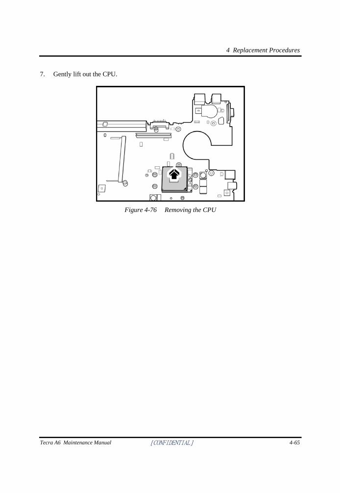
4 Replacement Procedures
Tecra A6 Maintenance Manual [CONFIDENTIAL] 4-65
7. Gently lift out the CPU.
Figure 4-76 Removing the CPU
4 Replacement Procedures
4-66 [CONFIDENTIAL] Tecra A6 Maintenance Manual
Installing the CPU
To install the CPU, follow the steps below and refer to the figures in the preceding section.
CAUTION: If you remove the heat sink, use the CPU grease tool to remove the grease on the CPU and heat sink. Reapply fresh grease before installing the heat sink.
1. Make sure that the notch on the cam is aligned with the open position of the CPU slot.
2. Seat the CPU aligning the triangle mark on the CPU with the one on the CPU socket. Make sure the alignment is exact to avoid damaging pins on the CPU.
3. Press the CPU softly with your fingers to insert into the socket and turn the cam on the CPU socket to the closed position with a flat-blade screwdriver to secure the CPU.
4. Seat the fan module and secure with the M2.5x3 screw on the top side of the system board.
5. Attach the fan connector.
6. Seat the heat sink over the CPU and secure with four screws in the order indicated on the heat sink.
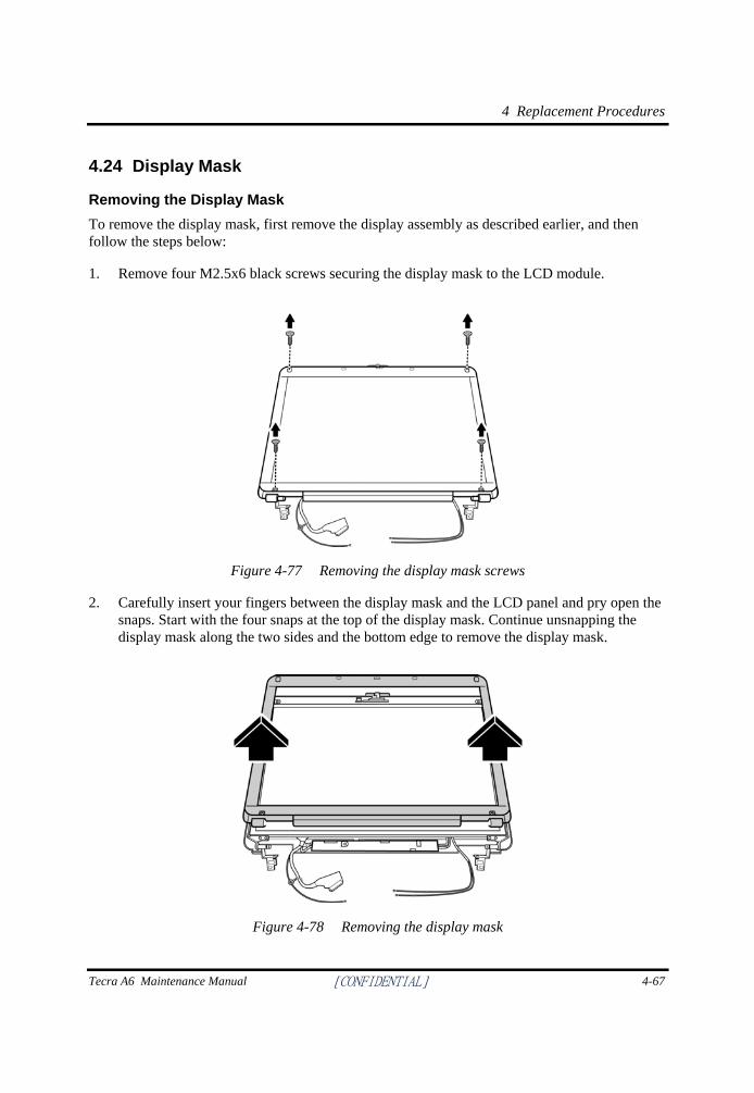
4 Replacement Procedures
Tecra A6 Maintenance Manual [CONFIDENTIAL] 4-67
4.24 Display Mask
Removing the Display Mask To remove the display mask, first remove the display assembly as described earlier, and then follow the steps below:
1. Remove four M2.5x6 black screws securing the display mask to the LCD module.
Figure 4-77 Removing the display mask screws
2. Carefully insert your fingers between the display mask and the LCD panel and pry open the snaps. Start with the four snaps at the top of the display mask. Continue unsnapping the display mask along the two sides and the bottom edge to remove the display mask.
Figure 4-78 Removing the display mask
4 Replacement Procedures
4-68 [CONFIDENTIAL] Tecra A6 Maintenance Manual
Installing the Display Mask
To install the display mask, follow the steps below and refer to the figures in the preceding section.
1. Seat the display mask and secure the snaps on each side.
2. Secure the display mask with four M2.5x6 screws.
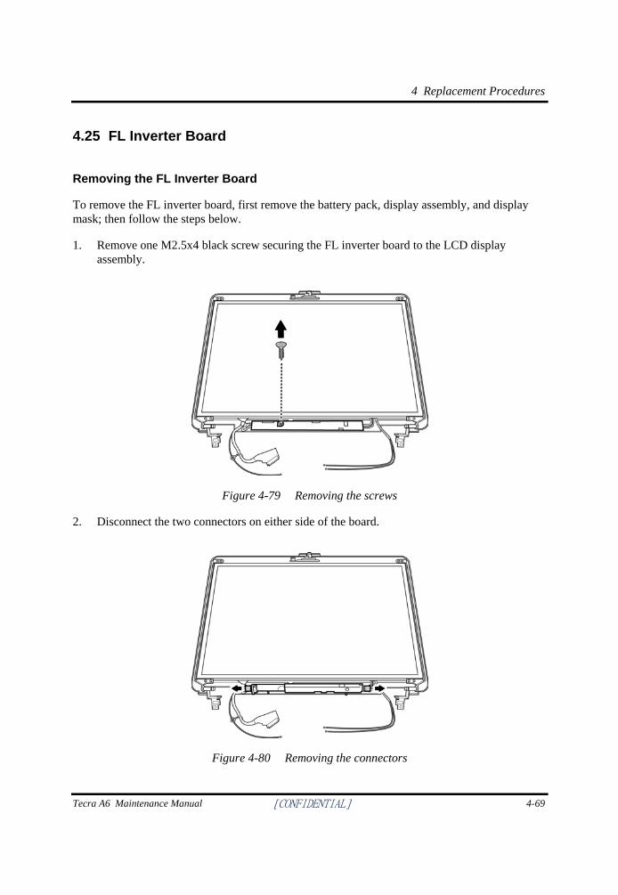
4 Replacement Procedures
Tecra A6 Maintenance Manual [CONFIDENTIAL] 4-69
4.25 FL Inverter Board
Removing the FL Inverter Board
To remove the FL inverter board, first remove the battery pack, display assembly, and display mask; then follow the steps below.
1. Remove one M2.5x4 black screw securing the FL inverter board to the LCD display assembly.
Figure 4-79 Removing the screws
2. Disconnect the two connectors on either side of the board.
Figure 4-80 Removing the connectors
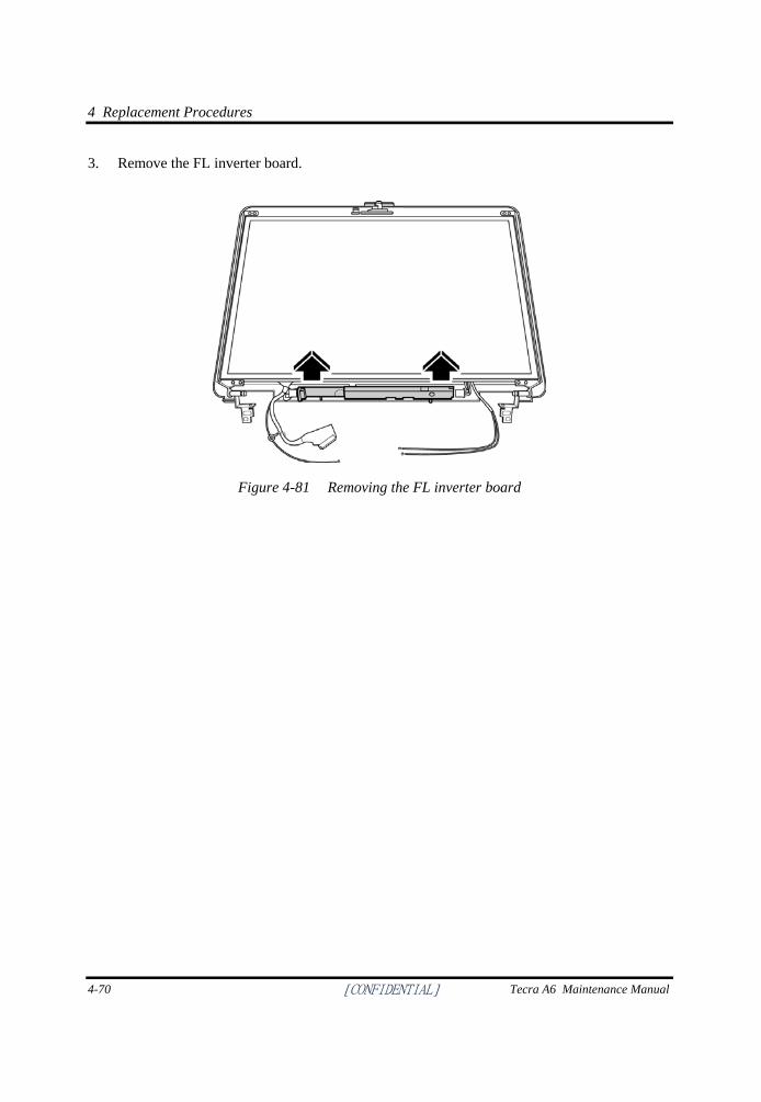
4 Replacement Procedures
4-70 [CONFIDENTIAL] Tecra A6 Maintenance Manual
3. Remove the FL inverter board.
Figure 4-81 Removing the FL inverter board
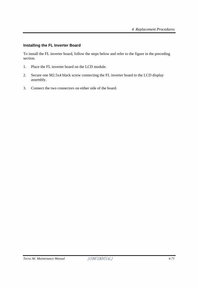
4 Replacement Procedures
Tecra A6 Maintenance Manual [CONFIDENTIAL] 4-71
Installing the FL Inverter Board
To install the FL inverter board, follow the steps below and refer to the figure in the preceding section.
1. Place the FL inverter board on the LCD module.
2. Secure one M2.5x4 black screw connecting the FL inverter board to the LCD display assembly.
3. Connect the two connectors on either side of the board.
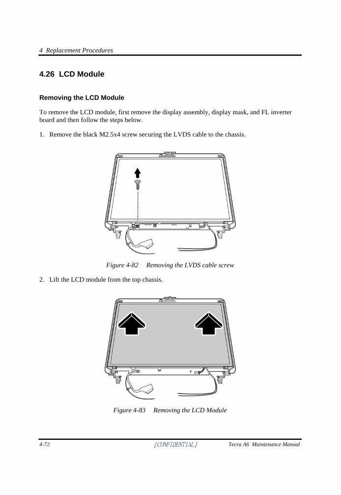
4 Replacement Procedures
4-72 [CONFIDENTIAL] Tecra A6 Maintenance Manual
4.26 LCD Module
Removing the LCD Module
To remove the LCD module, first remove the display assembly, display mask, and FL inverter board and then follow the steps below.
1. Remove the black M2.5x4 screw securing the LVDS cable to the chassis.
Figure 4-82 Removing the LVDS cable screw
2. Lift the LCD module from the top chassis.
Figure 4-83 Removing the LCD Module
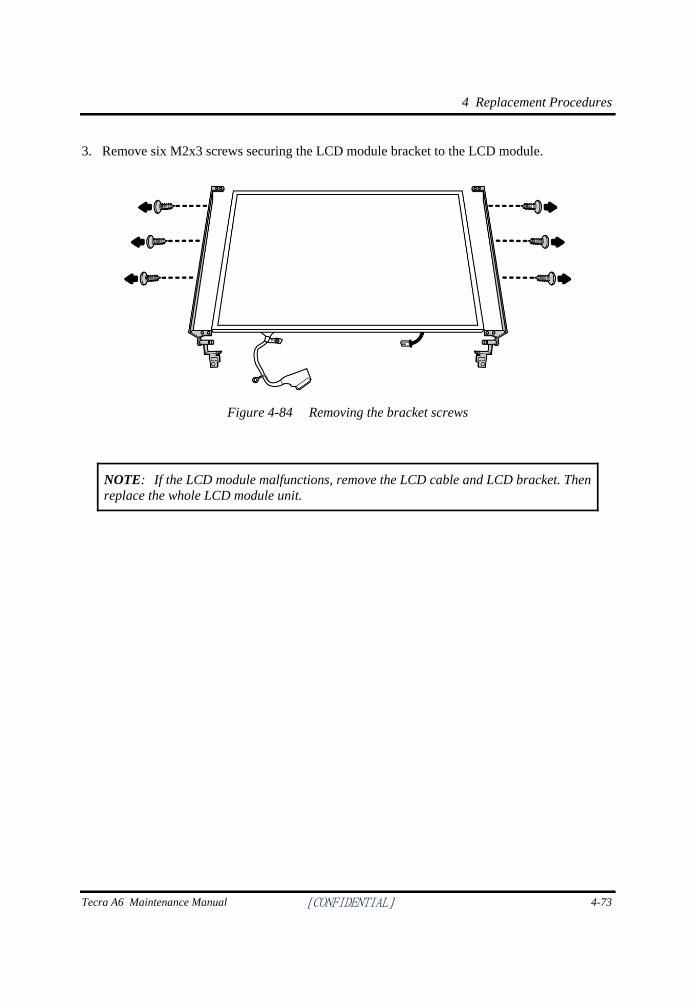
4 Replacement Procedures
Tecra A6 Maintenance Manual [CONFIDENTIAL] 4-73
3. Remove six M2x3 screws securing the LCD module bracket to the LCD module.
Figure 4-84 Removing the bracket screws
NOTE: If the LCD module malfunctions, remove the LCD cable and LCD bracket. Then replace the whole LCD module unit.
4 Replacement Procedures
4-74 [CONFIDENTIAL] Tecra A6 Maintenance Manual
Installing the LCD Module
To install the LCD module, follow the steps below and refer to the figures in the preceding section.
1. Seat the LCD module in the display assembly with the LCD module bracket and secure it with six M2x3 black screws. Note the L and R markings to make sure that the bracket arms are secured on the correct side.
2. Seat the LCD module with bracket on the chassis.
3. Secure the LVDS cable with the M2.5x4 screw to the chassis.
[CONFIDENTIAL]
Appendices
Appendices
App-ii [CONFIDENTIAL] Tecra A6 Maintenance Manual
Tecra A6 Maintenance Manual [CONFIDENTIAL] App-iii
Appendix Contents
Appendix A Handling the LCD Module................................................................................A-1
Appendix B Board Layout......................................................................................................B-1
B.1 System Board (FRDSY*) Top View ...............................................................................B-1
B.2 System Board (FRDSY*) Bottom View..........................................................................B-2
Appendix C Pin Assignments .................................................................................................C-1
C.1 JP19 SODIMM I/F (200-PIN) ........................................................................................ C-1
C.2 JP20 SODIMM I/F (200-pin) .......................................................................................... C-4
C.3 JP15 RGB I/F (15-pin) ................................................................................................... C-8
C.4 JP26 HDD I/F (22-pin) ................................................................................................... C-9
C.5 JP24 ODD I/F (52-pin) ................................................................................................. C-10
C.6 JP11 PC Card I/F (68-pin) ............................................................................................ C-11
C.7 JP28 Mini-Express I I/F (54-pin) .................................................................................. C-13
C.8 JP3 LVDS I/F (30-pin) .................................................................................................. C-14
C.9 JP16 Fan I/F (3-pin) ...................................................................................................... C-15
C.10 PJP1 AC Adaptor Connector(4-pin) ............................................................................. C-15
C.11 JP23 S-Video Connector (6-pin)................................................................................... C-15
C.12 JP13 RJ11-45 Connector (16-pin) ................................................................................ C-15
C.13 JP21 USB Connector (6-pin) ........................................................................................ C-16
C.14 JP14 Single USB Connector (6-pin) ............................................................................. C-16
C.15 JP27 MDC Connector (12-pin) ..................................................................................... C-16
C.16 JP4 SW/LED Connector (12-pin) ................................................................................. C-17
C.17 JP9 T/P Connector (6-pin) ............................................................................................ C-17
C.18 JP8 KB Connector (38-pin) .......................................................................................... C-18
C.19 JP25 1394 Connector (4-pin) ........................................................................................ C-19
C.20 JP2 SPK Connector (2-pin)........................................................................................... C-19
C.21 JP33 SPK Connector (2-pin)......................................................................................... C-19
C.22 PJP2 BATT Connector (7-pin) ..................................................................................... C-19
C.23 JP6 Fingerprint Board Connector (5-pin) ..................................................................... C-20
C.24 JP34 USB Board Connector (10-pin) ........................................................................... C-20
Appendices
App-iv [CONFIDENTIAL] Tecra A6 Maintenance Manual
C.25 J17 Docking I/F (240-pin) .............................................................................................C-21
C.26 J18 VGA/B I/F (200-pin) ..............................................................................................C-25
Appendix D Keyboard Scan/Character Codes.....................................................................D-1
Appendix E Key Layout ......................................................................................................... E-1
E.1 United States (US) Keyboard .......................................................................................... E-1
E.2 United Kingdom (UK) Keyboard .................................................................................... E-1
E.3 Spanish (SP) Keyboard.................................................................................................... E-2
E.4 Japanese (JA) Keyboard .................................................................................................. E-2
E.5 Korean (KO) Keyboard ................................................................................................... E-3
E.6 Canadian French (CF) Keyboard..................................................................................... E-3
E.7 Portuguese (PO) Keyboard .............................................................................................. E-4
E.8 US-INTE (US/INTE) Keyboard ...................................................................................... E-4
E.9 German (GR) Keyboard .................................................................................................. E-5
E.10 French (FR) Keyboard..................................................................................................... E-5
E.11 Chinese (CH) Keyboard .................................................................................................. E-6
E.12 Swiss-Darfon (SW) Keyboard......................................................................................... E-6
E.13 Italian (IT) Keyboard....................................................................................................... E-7
E.14 Belgian (BE) Keyboard ................................................................................................... E-7
E.15 Arabic (AR-E) Keyboard ................................................................................................ E-8
E.16 Czech (CZ) Keyboard...................................................................................................... E-8
E.17 Estonian (EST) Keyboard................................................................................................ E-9
E.18 Greek (GK) Keyboard ..................................................................................................... E-9
E.19 Hebrew (HB) Keyboard ................................................................................................ E-10
E.20 Hungarian (HG) Keyboard ............................................................................................ E-10
E.21 Norwegian (NW) Keyboard .......................................................................................... E-11
E.22 Dutch (DU) Keyboard ................................................................................................... E-11
E.23 Lithuanian (LI) Keyboard.............................................................................................. E-12
E.24 Russian (RU) Keyboard ................................................................................................ E-12
E.25 Turkish (TR) Keyboard ................................................................................................. E-13
E.26 Yugoslavian (YU) Keyboard......................................................................................... E-13
Tecra A6 Maintenance Manual [CONFIDENTIAL] App-v
E.27 Danish (DM) Keyboard .................................................................................................E-14
E.28 Slovak (SV) Keyboard ...................................................................................................E-14
E.29 Swedish (SD) Keyboard.................................................................................................E-15
Appendix F Series Screw Torque List...................................................................................F-1
Appendix G Reliability ........................................................................................................... G-1
Appendices
App-vi [CONFIDENTIAL] Tecra A6 Maintenance Manual
Figures
Figure B-1 System board (FRDSY*) layout (Top)................................................................B-1
Figure B.2 System board (FRDSY*) layout (Bottom)..........................................................B-2
Figure E-1 US keyboard ........................................................................................................ E-1
Figure E-2 UK keyboard ....................................................................................................... E-1
Figure E-3 SP keyboard ......................................................................................................... E-2
Figure E-4 JA keyboard ......................................................................................................... E-2
Figure E-5 KO keyboard ....................................................................................................... E-3
Figure E-6 CF keyboard ........................................................................................................ E-3
Figure E-7 PO keyboard ........................................................................................................ E-4
Figure E-8 US-INTE_ALPS keyboard .................................................................................. E-4
Figure E-9 GR keyboard........................................................................................................ E-5
Figure E-10 FR keyboard ........................................................................................................ E-5
Figure E-11 CH keyboard........................................................................................................ E-6
Figure E-12 Swiss-Darfon keyboard ....................................................................................... E-6
Figure E-13 IT keyboard ......................................................................................................... E-7
Figure E-14 BE keyboard ........................................................................................................ E-7
Figure E-15 AR-E keyboard .................................................................................................... E-8
Figure E-16 CZ keyboard ........................................................................................................ E-8
Figure E.17 EST keyboard ...................................................................................................... E-9
Figure E-18 GK keyboard ....................................................................................................... E-9
Figure E-19 HB keyboard...................................................................................................... E-10
Figure E-20 HG keyboard ..................................................................................................... E-10
Figure E-21 NW keyboard..................................................................................................... E-11
Figure E-22 DU keyboard ..................................................................................................... E-11
Figure E-23 LI keyboard ....................................................................................................... E-12
Figure E-24 RU keyboard...................................................................................................... E-12
Figure E-25 TR keyboard ...................................................................................................... E-13
Figure E-26 YU keyboard ..................................................................................................... E-13
Figure E-27 DM keyboard ..................................................................................................... E-14
Tecra A6 Maintenance Manual [CONFIDENTIAL] App-vii
Figure E-28 SV keyboard.......................................................................................................E-14
Figure E-29 SD keyboard.......................................................................................................E-15
Appendices
App-viii [CONFIDENTIAL] Tecra A6 Maintenance Manual
Tables
Table B-1 System board ICs (top and bottom) .....................................................................B-3
Table B-2 System board connectors (top and bottom) .........................................................B-4
Table C-1 SODIMM I/F pin assignments (200-PIN)...........................................................C-1
Table C-2 SODIMM I/F pin assignments (200-PIN)...........................................................C-4
Table C-3 RGB I/F pin assignments (15-pin) ......................................................................C-8
Table C-4 HDD I/F pin assignments (22-pin) ......................................................................C-9
Table C-5 ODD I/F pin assignments (52-pin) ....................................................................C-10
Table C-6 PC Card I/F pin assignments (68-pin) ...............................................................C-11
Table C-7 Mini-Express I I/F pin assignments (54-pin) .....................................................C-13
Table C-8 LVDS I/F pin assignments (30-pin) .................................................................C-14
Table C-9 Fan I/F pin assignments (3-pin) .........................................................................C-15
Table C-10 AC Adaptor Connector pin assignments (4-pin) ...............................................C-15
Table C-11 S-Video Connector pin assignments (6-pin) ....................................................C-15
Table C-12 RJ11-45 Connector pin assignments (16-pin) ..................................................C-15
Table C-13 USB Connector pin assignments (6-pin) ...........................................................C-16
Table C-14 Single USB Connector pin assignments (6-pin) ................................................C-16
Table C-15 MDC Connector pin assignments (12-pin) ........................................................C-16
Table C-16 SW/LED Connector pin assignments (12-pin) ..................................................C-17
Table C-17 T/P Connector pin assignments (6-pin) .............................................................C-17
Table C-18 KB Connector pin assignments (38-pin) ..........................................................C-18
Table C-19 1394 Connector pin assignments (4-pin) ...........................................................C-19
Table C-20 SPK Connector pin assignments (2-pin) ...........................................................C-19
Table C-21 SPK Connector pin assignments (2-pin) ...........................................................C-19
Table C-22 BATT Connector pin assignments (7-pin) .......................................................C-19
Table C-23 Fingerprint Board Connector pin assignments (5-pin) ......................................C-20
Table C-24 USB Board Connector pin assignments (10-pin) .............................................C-20
Table C-25 Docking I/F pin assignments (240-pin) ............................................................C-21
Table C-26 VGA/B I/F pin assignments (200-pin) .............................................................C-25
Tecra A6 Maintenance Manual [CONFIDENTIAL] App-ix
Table D-1 Scan codes (set 1 and set 2) ................................................................................ D-1
Table D-2 Scan codes with left Shift key............................................................................. D-5
Table D-3 Scan codes in Numlock mode............................................................................. D-6
Table D-4 Scan codes with Fn key....................................................................................... D-6
Table D-5 Scan codes in overlay mode................................................................................ D-7
Table D-6 No.124 key scan code ......................................................................................... D-7
Table D-7 No.126 key scan code ......................................................................................... D-8
Table F-1 Series Screw Torque List .....................................................................................F-1
Table G-1 MTBF.................................................................................................................. G-1
Appendices
App-x [CONFIDENTIAL] Tecra A6 Maintenance Manual
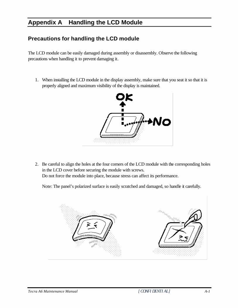
Tecra A6 Maintenance Manual [CONFIDENTIAL] A-1
Appendix A
Appendix A Handling the LCD Module
Precautions for handling the LCD module
The LCD module can be easily damaged during assembly or disassembly. Observe the following precautions when handling it to prevent damaging it.
1. When installing the LCD module in the display assembly, make sure that you seat it so that it is properly aligned and maximum visibility of the display is maintained.
2. Be careful to align the holes at the four corners of the LCD module with the corresponding holes in the LCD cover before securing the module with screws. Do not force the module into place, because stress can affect its performance.
Note: The panel’s polarized surface is easily scratched and damaged, so handle it carefully.
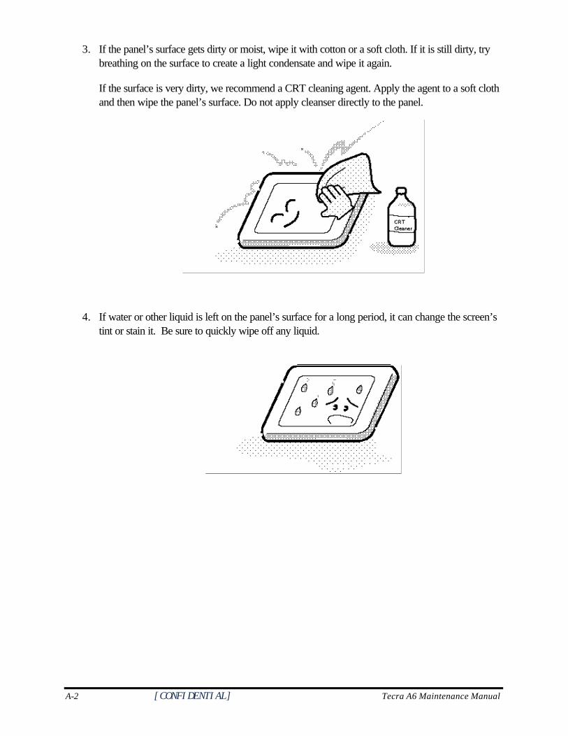
A-2 [CONFIDENTIAL] Tecra A6 Maintenance Manual
3. If the panel’s surface gets dirty or moist, wipe it with cotton or a soft cloth. If it is still dirty, try breathing on the surface to create a light condensate and wipe it again.
If the surface is very dirty, we recommend a CRT cleaning agent. Apply the agent to a soft cloth and then wipe the panel’s surface. Do not apply cleanser directly to the panel.
4. If water or other liquid is left on the panel’s surface for a long period, it can change the screen’s tint or stain it. Be sure to quickly wipe off any liquid.
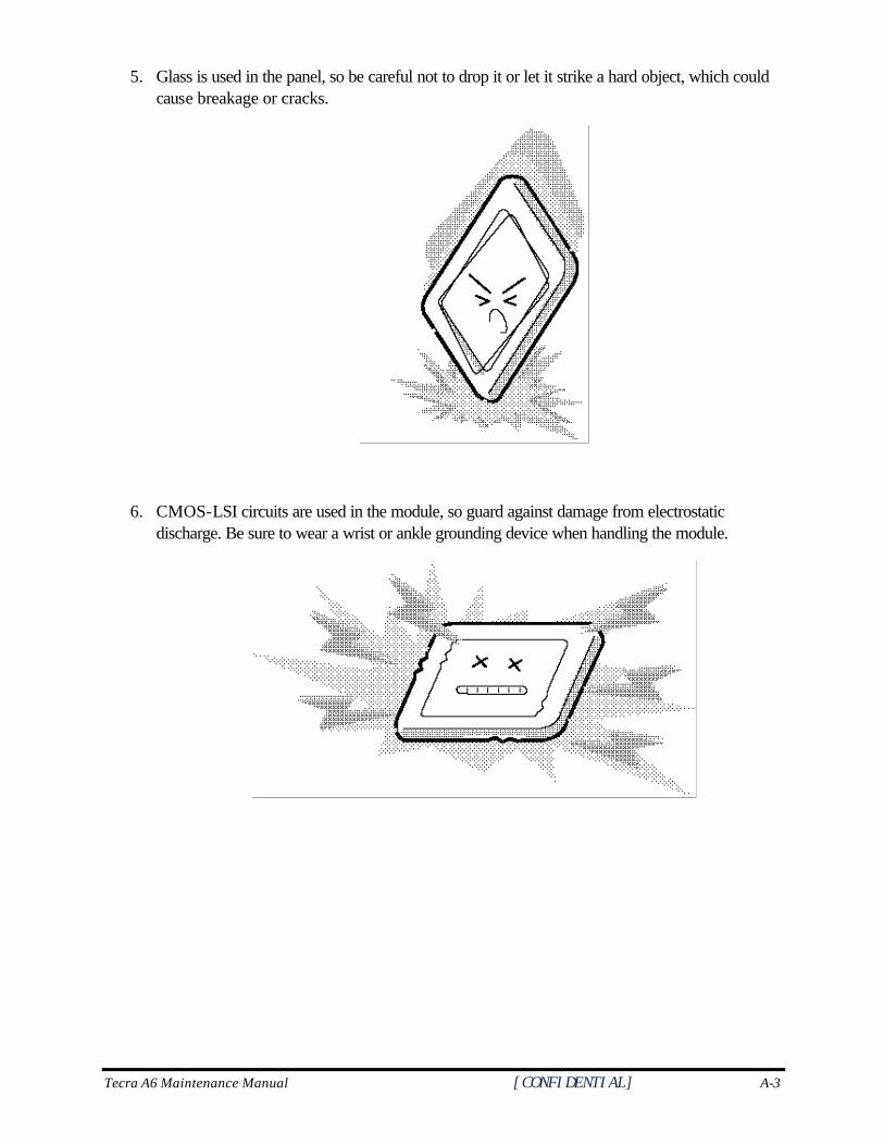
Tecra A6 Maintenance Manual [CONFIDENTIAL] A-3
5. Glass is used in the panel, so be careful not to drop it or let it strike a hard object, which could cause breakage or cracks.
6. CMOS-LSI circuits are used in the module, so guard against damage from electrostatic discharge. Be sure to wear a wrist or ankle grounding device when handling the module.
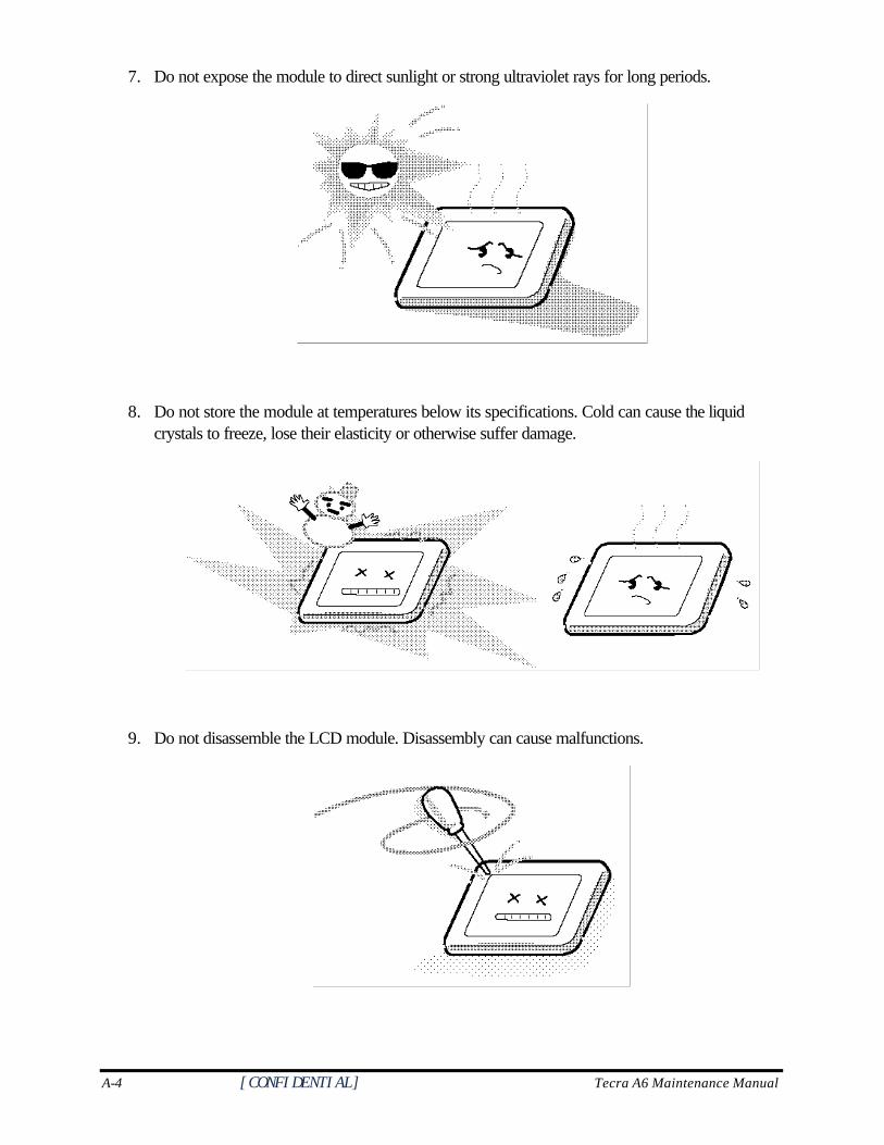
A-4 [CONFIDENTIAL] Tecra A6 Maintenance Manual
7. Do not expose the module to direct sunlight or strong ultraviolet rays for long periods.
8. Do not store the module at temperatures below its specifications. Cold can cause the liquid crystals to freeze, lose their elasticity or otherwise suffer damage.
9. Do not disassemble the LCD module. Disassembly can cause malfunctions.
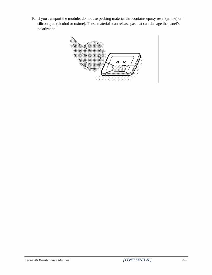
Tecra A6 Maintenance Manual [CONFIDENTIAL] A-5
10. If you transport the module, do not use packing material that contains epoxy resin (amine) or silicon glue (alcohol or oxime). These materials can release gas that can damage the panel’s polarization.

A-6 [CONFIDENTIAL] Tecra A6 Maintenance Manual
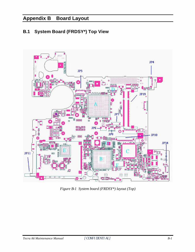
Tecra A6 Maintenance Manual [CONFIDENTIAL] B-1
Appendix B
Appendix B Board Layout
B.1 System Board (FRDSY*) Top View
Figure B-1 System board (FRDSY*) layout (Top)
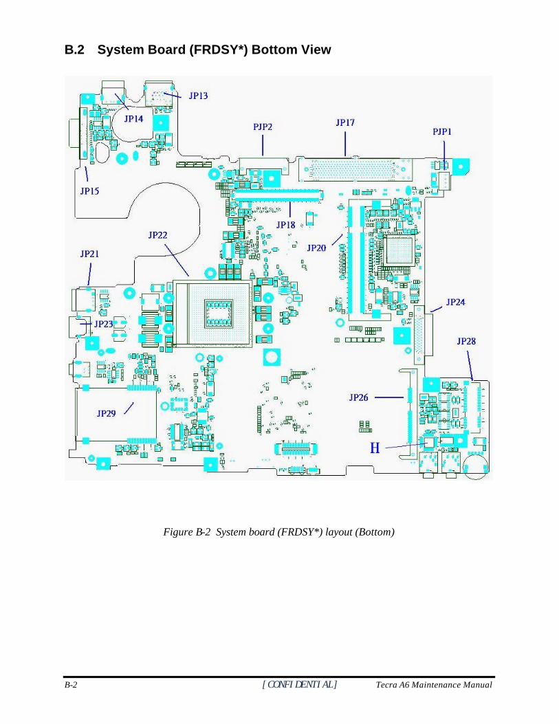
B-2 [CONFIDENTIAL] Tecra A6 Maintenance Manual
B.2 System Board (FRDSY*) Bottom View
Figure B-2 System board (FRDSY*) layout (Bottom)
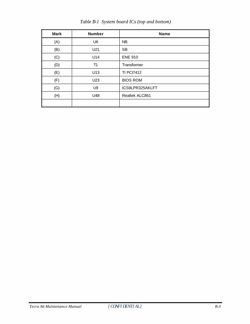
Tecra A6 Maintenance Manual [CONFIDENTIAL] B-3
Table B-1 System board ICs (top and bottom)
Mark Number Name
(A) U6 NB
(B) U21 SB
(C) U14 ENE 910
(D) T1 Transformer
(E) U13 TI PCI7412
(F) U23 BIOS ROM
(G) U9 ICS9LPR325AKLFT
(H) U48 Realtek ALC861
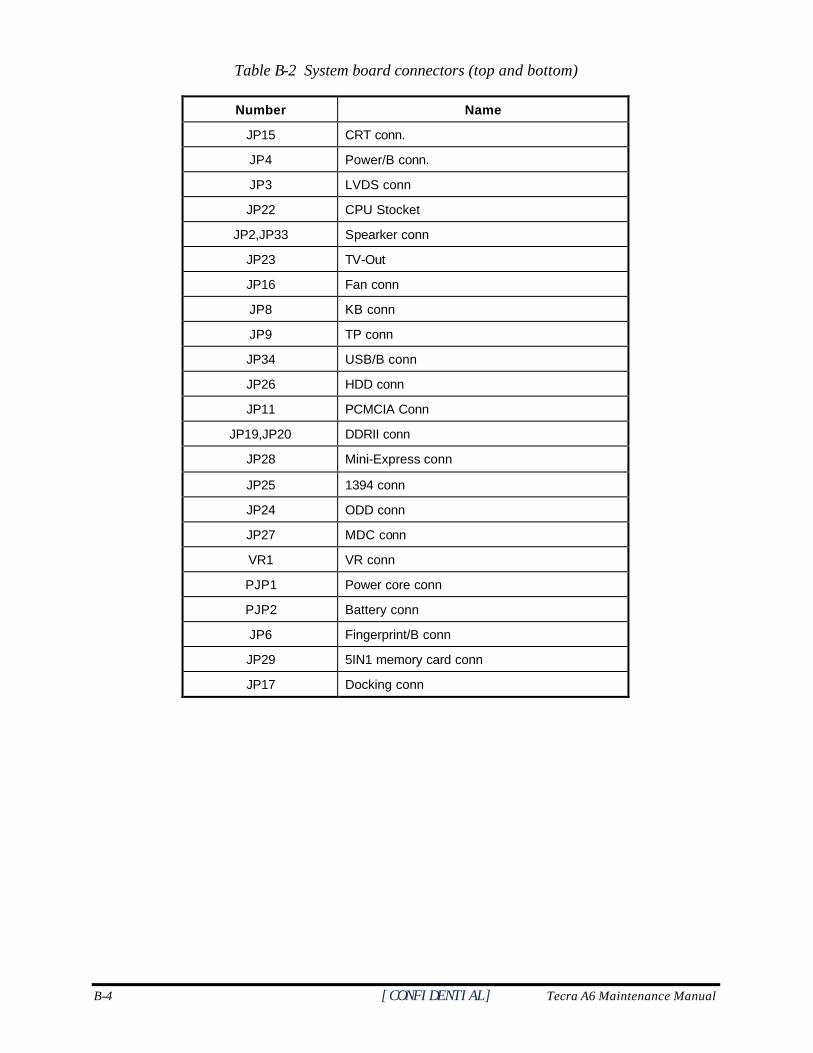
B-4 [CONFIDENTIAL] Tecra A6 Maintenance Manual
Table B-2 System board connectors (top and bottom)
Number Name
JP15 CRT conn.
JP4 Power/B conn.
JP3 LVDS conn
JP22 CPU Stocket
JP2,JP33 Spearker conn
JP23 TV-Out
JP16 Fan conn
JP8 KB conn
JP9 TP conn
JP34 USB/B conn
JP26 HDD conn
JP11 PCMCIA Conn
JP19,JP20 DDRII conn
JP28 Mini-Express conn
JP25 1394 conn
JP24 ODD conn
JP27 MDC conn
VR1 VR conn
PJP1 Power core conn
PJP2 Battery conn
JP6 Fingerprint/B conn
JP29 5IN1 memory card conn
JP17 Docking conn
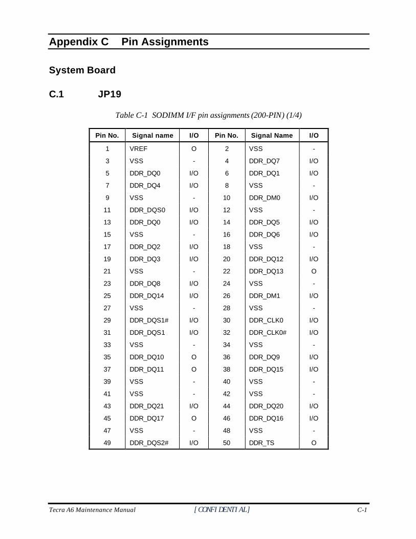
Tecra A6 Maintenance Manual [CONFIDENTIAL] C-1
C.
Appendix C Pin Assignments
System Board
C.1 JP19
Table C-1 SODIMM I/F pin assignments (200-PIN) (1/4)
Pin No. Signal name I/O Pin No. Signal Name I/O
1 VREF O 2 VSS -
3 VSS - 4 DDR_DQ7 I/O
5 DDR_DQ0 I/O 6 DDR_DQ1 I/O
7 DDR_DQ4 I/O 8 VSS -
9 VSS - 10 DDR_DM0 I/O
11 DDR_DQS0 I/O 12 VSS -
13 DDR_DQ0 I/O 14 DDR_DQ5 I/O
15 VSS - 16 DDR_DQ6 I/O
17 DDR_DQ2 I/O 18 VSS -
19 DDR_DQ3 I/O 20 DDR_DQ12 I/O
21 VSS - 22 DDR_DQ13 O
23 DDR_DQ8 I/O 24 VSS -
25 DDR_DQ14 I/O 26 DDR_DM1 I/O
27 VSS - 28 VSS -
29 DDR_DQS1# I/O 30 DDR_CLK0 I/O
31 DDR_DQS1 I/O 32 DDR_CLK0# I/O
33 VSS - 34 VSS -
35 DDR_DQ10 O 36 DDR_DQ9 I/O
37 DDR_DQ11 O 38 DDR_DQ15 I/O
39 VSS - 40 VSS -
41 VSS - 42 VSS -
43 DDR_DQ21 I/O 44 DDR_DQ20 I/O
45 DDR_DQ17 O 46 DDR_DQ16 I/O
47 VSS - 48 VSS -
49 DDR_DQS2# I/O 50 DDR_TS O
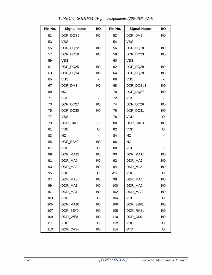
C-2 [CONFIDENTIAL] Tecra A6 Maintenance Manual
Table C-1 SODIMM I/F pin assignments (200-PIN) (2/4)
Pin No. Signal name I/O Pin No. Signal Name I/O
51 DDR_DQS2 I/O 52 DDR_DM2 I/O
53 VSS - 54 VSS -
55 DDR_DQ22 I/O 56 DDR_DQ18 I/O
57 DDR_DQ19 I/O 58 DDR_DQ23 I/O
59 VSS - 60 VSS -
61 DDR_DQ25 I/O 62 DDR_DQ29 I/O
63 DDR_DQ24 I/O 64 DDR_DQ28 I/O
65 VSS - 66 VSS -
67 DDR_DM3 I/O 68 DDR_DQS#3 I/O
69 NC - 70 DDR_DQS3 I/O
71 VSS - 72 VSS -
73 DDR_DQ27 I/O 74 DDR_DQ26 I/O
75 DDR_DQ30 I/O 76 DDR_DQ31 I/O
77 VSS - 78 VDD O
79 DDR_CKE0 I/0 80 DDR_CKE1 I/O
81 VDD O 82 VDD O
83 NC - 84 NC -
85 DDR_BS#2 I/O 86 NC -
87 VDD O 88 VDD -
89 DDR_MA12 I/O 90 DDR_MA11 I/O
91 DDR_MA9 I/O 92 DDR_MA7 I/O
93 DDR_MA8 I/O 94 DDR_MA6 I/O
95 VDD O A96 VDD O
97 DDR_MA5 I/O 98 DDR_MA4 I/O
99 DDR_MA3 I/O 100 DDR_MA2 I/O
101 DDR_MA1 I/O 102 DDR_MA0 I/O
103 VDD O 104 VDD O
105 DDR_MA10 I/O 106 DDR_BS#1 I/O
107 DDR_BS#0 I/O 108 DDR_RAS# I/O
109 DDR_WE# I/O 110 DDR_CS0 I/O
111 VDD O 112 VDD O
113 DDR_CAS# I/O 114 OTD O
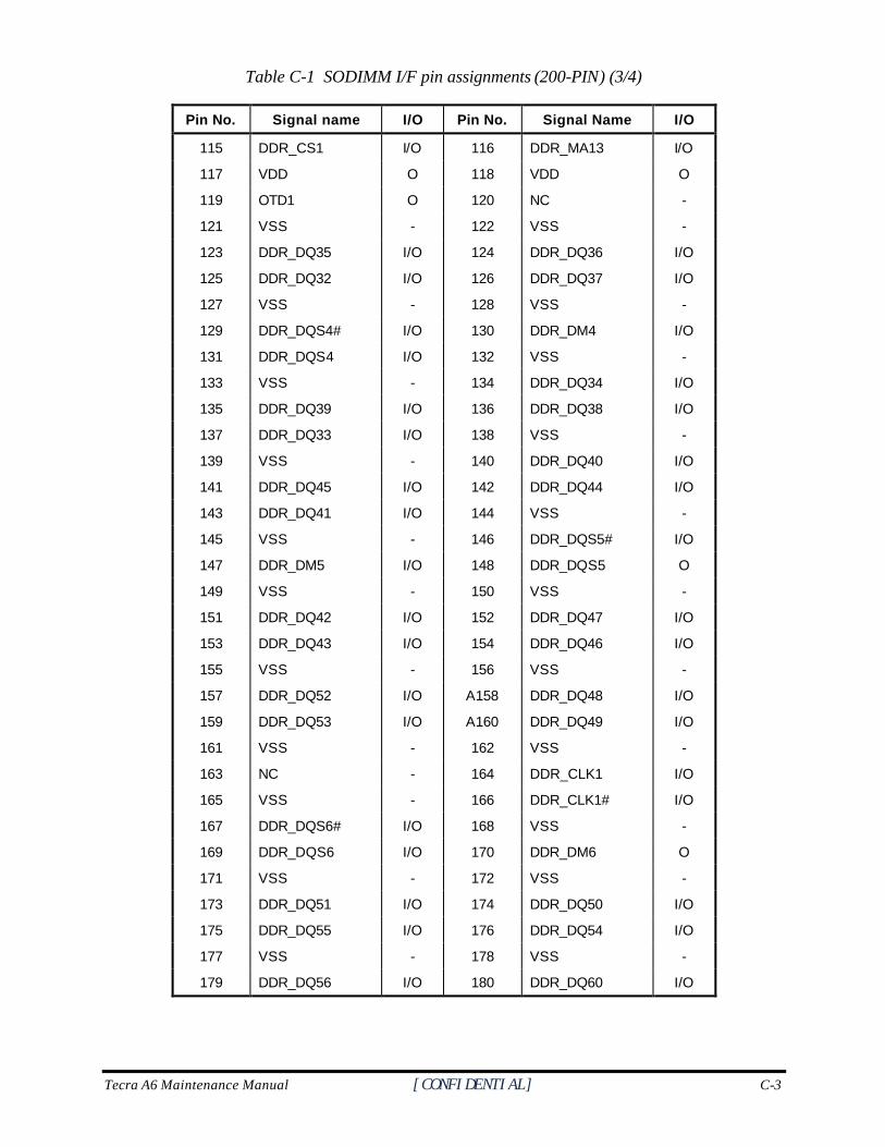
Tecra A6 Maintenance Manual [CONFIDENTIAL] C-3
Table C-1 SODIMM I/F pin assignments (200-PIN) (3/4)
Pin No. Signal name I/O Pin No. Signal Name I/O
115 DDR_CS1 I/O 116 DDR_MA13 I/O
117 VDD O 118 VDD O
119 OTD1 O 120 NC -
121 VSS - 122 VSS -
123 DDR_DQ35 I/O 124 DDR_DQ36 I/O
125 DDR_DQ32 I/O 126 DDR_DQ37 I/O
127 VSS - 128 VSS -
129 DDR_DQS4# I/O 130 DDR_DM4 I/O
131 DDR_DQS4 I/O 132 VSS -
133 VSS - 134 DDR_DQ34 I/O
135 DDR_DQ39 I/O 136 DDR_DQ38 I/O
137 DDR_DQ33 I/O 138 VSS -
139 VSS - 140 DDR_DQ40 I/O
141 DDR_DQ45 I/O 142 DDR_DQ44 I/O
143 DDR_DQ41 I/O 144 VSS -
145 VSS - 146 DDR_DQS5# I/O
147 DDR_DM5 I/O 148 DDR_DQS5 O
149 VSS - 150 VSS -
151 DDR_DQ42 I/O 152 DDR_DQ47 I/O
153 DDR_DQ43 I/O 154 DDR_DQ46 I/O
155 VSS - 156 VSS -
157 DDR_DQ52 I/O A158 DDR_DQ48 I/O
159 DDR_DQ53 I/O A160 DDR_DQ49 I/O
161 VSS - 162 VSS -
163 NC - 164 DDR_CLK1 I/O
165 VSS - 166 DDR_CLK1# I/O
167 DDR_DQS6# I/O 168 VSS -
169 DDR_DQS6 I/O 170 DDR_DM6 O
171 VSS - 172 VSS -
173 DDR_DQ51 I/O 174 DDR_DQ50 I/O
175 DDR_DQ55 I/O 176 DDR_DQ54 I/O
177 VSS - 178 VSS -
179 DDR_DQ56 I/O 180 DDR_DQ60 I/O
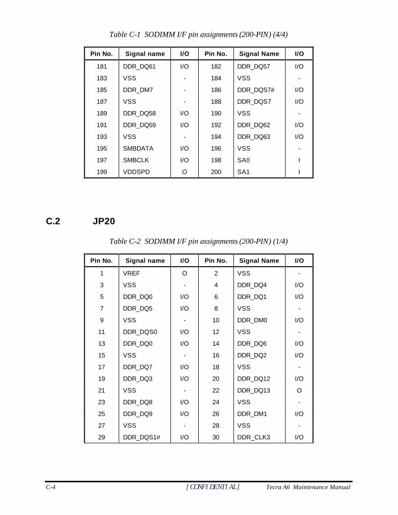
C-4 [CONFIDENTIAL] Tecra A6 Maintenance Manual
Table C-1 SODIMM I/F pin assignments (200-PIN) (4/4)
Pin No. Signal name I/O Pin No. Signal Name I/O
181 DDR_DQ61 I/O 182 DDR_DQ57 I/O
183 VSS - 184 VSS -
185 DDR_DM7 - 186 DDR_DQS7# I/O
187 VSS - 188 DDR_DQS7 I/O
189 DDR_DQ58 I/O 190 VSS -
191 DDR_DQ59 I/O 192 DDR_DQ62 I/O
193 VSS - 194 DDR_DQ63 I/O
195 SMBDATA I/O 196 VSS -
197 SMBCLK I/O 198 SA0 I
199 VDDSPD O 200 SA1 I
C.2 JP20
Table C-2 SODIMM I/F pin assignments (200-PIN) (1/4)
Pin No. Signal name I/O Pin No. Signal Name I/O
1 VREF O 2 VSS -
3 VSS - 4 DDR_DQ4 I/O
5 DDR_DQ0 I/O 6 DDR_DQ1 I/O
7 DDR_DQ5 I/O 8 VSS -
9 VSS - 10 DDR_DM0 I/O
11 DDR_DQS0 I/O 12 VSS -
13 DDR_DQ0 I/O 14 DDR_DQ6 I/O
15 VSS - 16 DDR_DQ2 I/O
17 DDR_DQ7 I/O 18 VSS -
19 DDR_DQ3 I/O 20 DDR_DQ12 I/O
21 VSS - 22 DDR_DQ13 O
23 DDR_DQ8 I/O 24 VSS -
25 DDR_DQ9 I/O 26 DDR_DM1 I/O
27 VSS - 28 VSS -
29 DDR_DQS1# I/O 30 DDR_CLK3 I/O
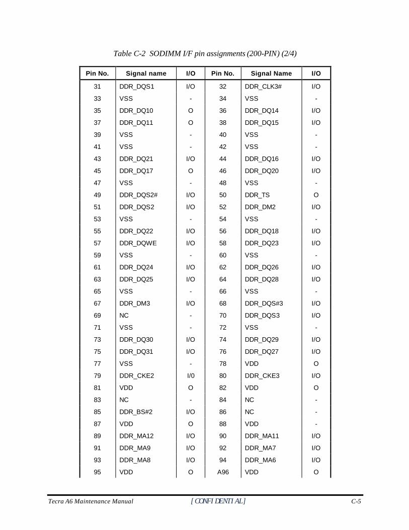
Tecra A6 Maintenance Manual [CONFIDENTIAL] C-5
Table C-2 SODIMM I/F pin assignments (200-PIN) (2/4)
Pin No. Signal name I/O Pin No. Signal Name I/O
31 DDR_DQS1 I/O 32 DDR_CLK3# I/O
33 VSS - 34 VSS -
35 DDR_DQ10 O 36 DDR_DQ14 I/O
37 DDR_DQ11 O 38 DDR_DQ15 I/O
39 VSS - 40 VSS -
41 VSS - 42 VSS -
43 DDR_DQ21 I/O 44 DDR_DQ16 I/O
45 DDR_DQ17 O 46 DDR_DQ20 I/O
47 VSS - 48 VSS -
49 DDR_DQS2# I/O 50 DDR_TS O
51 DDR_DQS2 I/O 52 DDR_DM2 I/O
53 VSS - 54 VSS -
55 DDR_DQ22 I/O 56 DDR_DQ18 I/O
57 DDR_DQWE I/O 58 DDR_DQ23 I/O
59 VSS - 60 VSS -
61 DDR_DQ24 I/O 62 DDR_DQ26 I/O
63 DDR_DQ25 I/O 64 DDR_DQ28 I/O
65 VSS - 66 VSS -
67 DDR_DM3 I/O 68 DDR_DQS#3 I/O
69 NC - 70 DDR_DQS3 I/O
71 VSS - 72 VSS -
73 DDR_DQ30 I/O 74 DDR_DQ29 I/O
75 DDR_DQ31 I/O 76 DDR_DQ27 I/O
77 VSS - 78 VDD O
79 DDR_CKE2 I/0 80 DDR_CKE3 I/O
81 VDD O 82 VDD O
83 NC - 84 NC -
85 DDR_BS#2 I/O 86 NC -
87 VDD O 88 VDD -
89 DDR_MA12 I/O 90 DDR_MA11 I/O
91 DDR_MA9 I/O 92 DDR_MA7 I/O
93 DDR_MA8 I/O 94 DDR_MA6 I/O
95 VDD O A96 VDD O
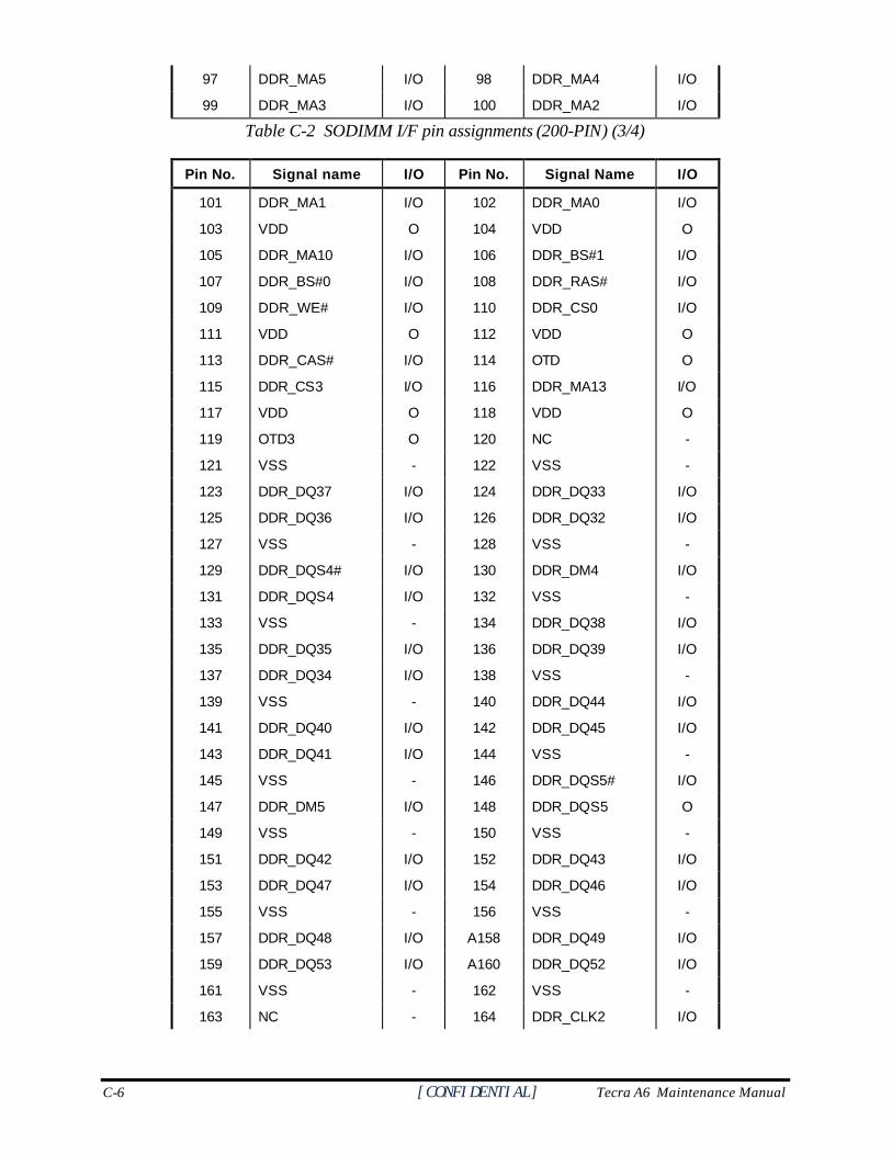
C-6 [CONFIDENTIAL] Tecra A6 Maintenance Manual
97 DDR_MA5 I/O 98 DDR_MA4 I/O
99 DDR_MA3 I/O 100 DDR_MA2 I/O
Table C-2 SODIMM I/F pin assignments (200-PIN) (3/4)
Pin No. Signal name I/O Pin No. Signal Name I/O
101 DDR_MA1 I/O 102 DDR_MA0 I/O
103 VDD O 104 VDD O
105 DDR_MA10 I/O 106 DDR_BS#1 I/O
107 DDR_BS#0 I/O 108 DDR_RAS# I/O
109 DDR_WE# I/O 110 DDR_CS0 I/O
111 VDD O 112 VDD O
113 DDR_CAS# I/O 114 OTD O
115 DDR_CS3 I/O 116 DDR_MA13 I/O
117 VDD O 118 VDD O
119 OTD3 O 120 NC -
121 VSS - 122 VSS -
123 DDR_DQ37 I/O 124 DDR_DQ33 I/O
125 DDR_DQ36 I/O 126 DDR_DQ32 I/O
127 VSS - 128 VSS -
129 DDR_DQS4# I/O 130 DDR_DM4 I/O
131 DDR_DQS4 I/O 132 VSS -
133 VSS - 134 DDR_DQ38 I/O
135 DDR_DQ35 I/O 136 DDR_DQ39 I/O
137 DDR_DQ34 I/O 138 VSS -
139 VSS - 140 DDR_DQ44 I/O
141 DDR_DQ40 I/O 142 DDR_DQ45 I/O
143 DDR_DQ41 I/O 144 VSS -
145 VSS - 146 DDR_DQS5# I/O
147 DDR_DM5 I/O 148 DDR_DQS5 O
149 VSS - 150 VSS -
151 DDR_DQ42 I/O 152 DDR_DQ43 I/O
153 DDR_DQ47 I/O 154 DDR_DQ46 I/O
155 VSS - 156 VSS -
157 DDR_DQ48 I/O A158 DDR_DQ49 I/O
159 DDR_DQ53 I/O A160 DDR_DQ52 I/O
161 VSS - 162 VSS -
163 NC - 164 DDR_CLK2 I/O
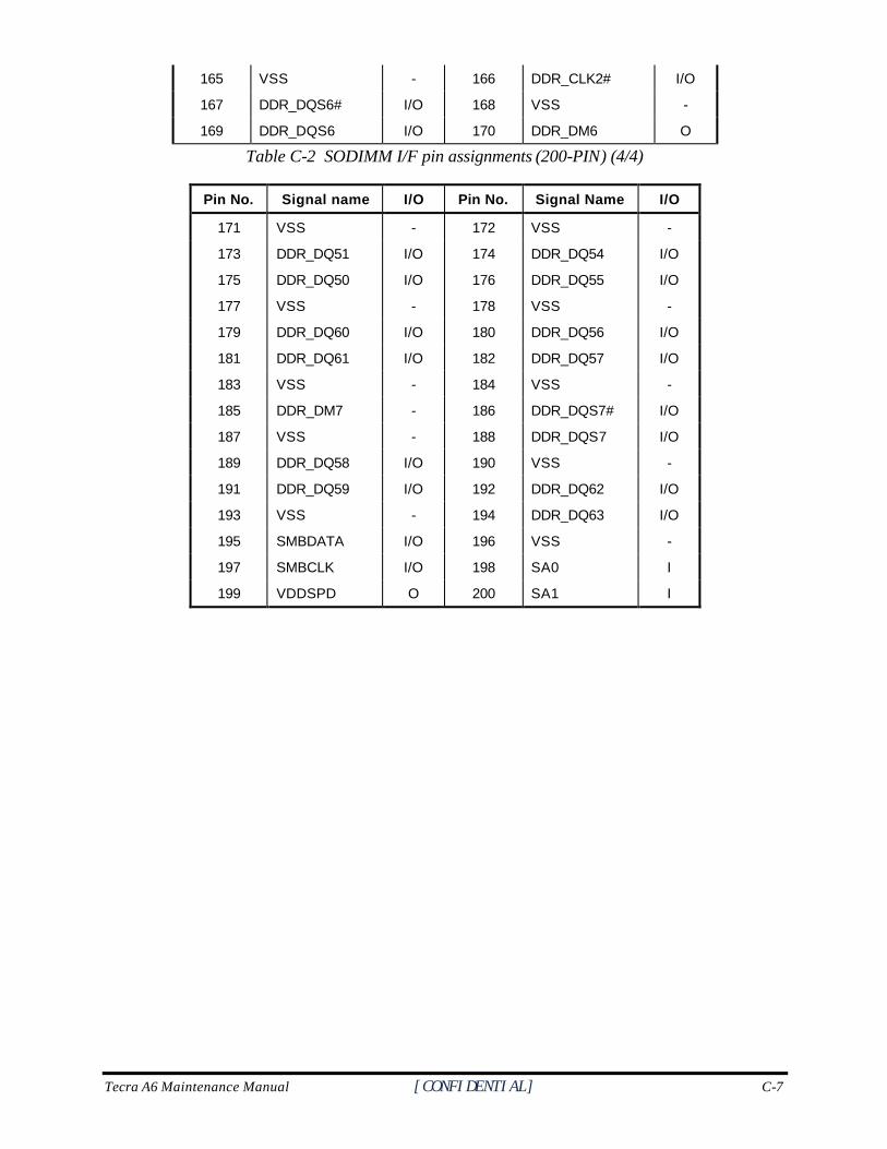
Tecra A6 Maintenance Manual [CONFIDENTIAL] C-7
165 VSS - 166 DDR_CLK2# I/O
167 DDR_DQS6# I/O 168 VSS -
169 DDR_DQS6 I/O 170 DDR_DM6 O
Table C-2 SODIMM I/F pin assignments (200-PIN) (4/4)
Pin No. Signal name I/O Pin No. Signal Name I/O
171 VSS - 172 VSS -
173 DDR_DQ51 I/O 174 DDR_DQ54 I/O
175 DDR_DQ50 I/O 176 DDR_DQ55 I/O
177 VSS - 178 VSS -
179 DDR_DQ60 I/O 180 DDR_DQ56 I/O
181 DDR_DQ61 I/O 182 DDR_DQ57 I/O
183 VSS - 184 VSS -
185 DDR_DM7 - 186 DDR_DQS7# I/O
187 VSS - 188 DDR_DQS7 I/O
189 DDR_DQ58 I/O 190 VSS -
191 DDR_DQ59 I/O 192 DDR_DQ62 I/O
193 VSS - 194 DDR_DQ63 I/O
195 SMBDATA I/O 196 VSS -
197 SMBCLK I/O 198 SA0 I
199 VDDSPD O 200 SA1 I
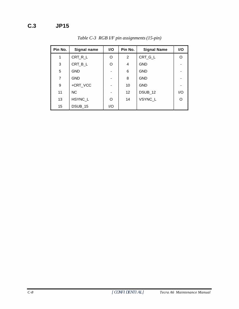
C-8 [CONFIDENTIAL] Tecra A6 Maintenance Manual
C.3 JP15
Table C-3 RGB I/F pin assignments (15-pin)
Pin No. Signal name I/O Pin No. Signal Name I/O
1 CRT_R_L O 2 CRT_G_L O
3 CRT_B_L O 4 GND -
5 GND - 6 GND -
7 GND - 8 GND -
9 +CRT_VCC - 10 GND -
11 NC - 12 DSUB_12 I/O
13 HSYNC_L O 14 VSYNC_L O
15 DSUB_15 I/O
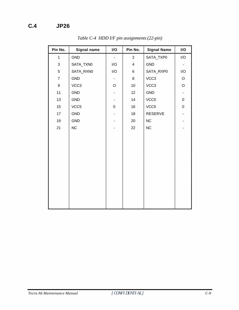
Tecra A6 Maintenance Manual [CONFIDENTIAL] C-9
C.4 JP26
Table C-4 HDD I/F pin assignments (22-pin)
Pin No. Signal name I/O Pin No. Signal Name I/O
1 GND - 2 SATA_TXP0 I/O
3 SATA_TXN0 I/O 4 GND -
5 SATA_RXN0 I/O 6 SATA_RXP0 I/O
7 GND - 8 VCC3 O
9 VCC3 O 10 VCC3 O
11 GND - 12 GND -
13 GND - 14 VCC5 0
15 VCC5 0 16 VCC5 0
17 GND - 18 RESERVE -
19 GND - 20 NC -
21 NC - 22 NC -
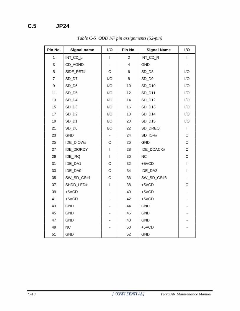
C-10 [CONFIDENTIAL] Tecra A6 Maintenance Manual
C.5 JP24
Table C-5 ODD I/F pin assignments (52-pin)
Pin No. Signal name I/O Pin No. Signal Name I/O
1 INT_CD_L I 2 INT_CD_R I
3 CD_AGND - 4 GND -
5 SIDE_RST# O 6 SD_D8 I/O
7 SD_D7 I/O 8 SD_D9 I/O
9 SD_D6 I/O 10 SD_D10 I/O
11 SD_D5 I/O 12 SD_D11 I/O
13 SD_D4 I/O 14 SD_D12 I/O
15 SD_D3 I/O 16 SD_D13 I/O
17 SD_D2 I/O 18 SD_D14 I/O
19 SD_D1 I/O 20 SD_D15 I/O
21 SD_D0 I/O 22 SD_DREQ I
23 GND - 24 SD_IOR# O
25 IDE_DIOW# O 26 GND O
27 IDE_DIORDY I 28 IDE_DDACK# O
29 IDE_IRQ I 30 NC O
31 IDE_DA1 O 32 +5VCD I
33 IDE_DA0 O 34 IDE_DA2 I
35 SW_SD_CS#1 O 36 SW_SD_CS#3 -
37 SHDD_LED# I 38 +5VCD O
39 +5VCD - 40 +5VCD -
41 +5VCD - 42 +5VCD -
43 GND - 44 GND -
45 GND - 46 GND -
47 GND - 48 GND -
49 NC - 50 +5VCD -
51 GND 52 GND
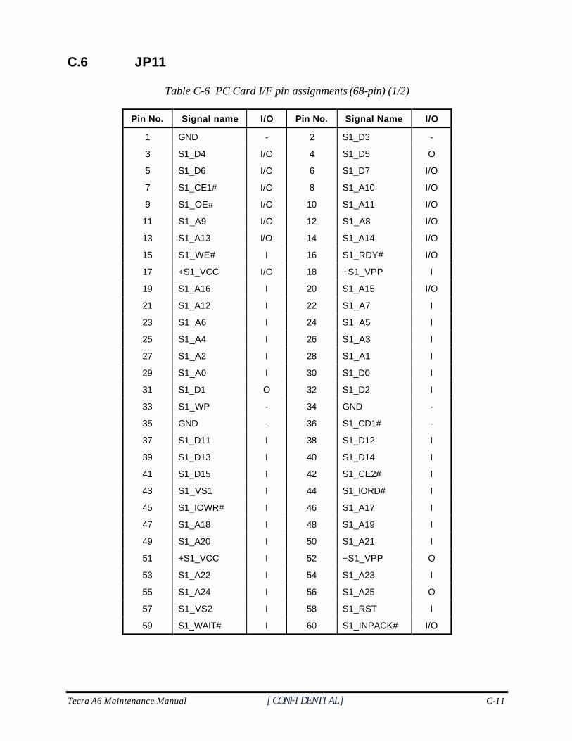
Tecra A6 Maintenance Manual [CONFIDENTIAL] C-11
C.6 JP11
Table C-6 PC Card I/F pin assignments (68-pin) (1/2)
Pin No. Signal name I/O Pin No. Signal Name I/O
1 GND - 2 S1_D3 -
3 S1_D4 I/O 4 S1_D5 O
5 S1_D6 I/O 6 S1_D7 I/O
7 S1_CE1# I/O 8 S1_A10 I/O
9 S1_OE# I/O 10 S1_A11 I/O
11 S1_A9 I/O 12 S1_A8 I/O
13 S1_A13 I/O 14 S1_A14 I/O
15 S1_WE# I 16 S1_RDY# I/O
17 +S1_VCC I/O 18 +S1_VPP I
19 S1_A16 I 20 S1_A15 I/O
21 S1_A12 I 22 S1_A7 I
23 S1_A6 I 24 S1_A5 I
25 S1_A4 I 26 S1_A3 I
27 S1_A2 I 28 S1_A1 I
29 S1_A0 I 30 S1_D0 I
31 S1_D1 O 32 S1_D2 I
33 S1_WP - 34 GND -
35 GND - 36 S1_CD1# -
37 S1_D11 I 38 S1_D12 I
39 S1_D13 I 40 S1_D14 I
41 S1_D15 I 42 S1_CE2# I
43 S1_VS1 I 44 S1_IORD# I
45 S1_IOWR# I 46 S1_A17 I
47 S1_A18 I 48 S1_A19 I
49 S1_A20 I 50 S1_A21 I
51 +S1_VCC I 52 +S1_VPP O
53 S1_A22 I 54 S1_A23 I
55 S1_A24 I 56 S1_A25 O
57 S1_VS2 I 58 S1_RST I
59 S1_WAIT# I 60 S1_INPACK# I/O
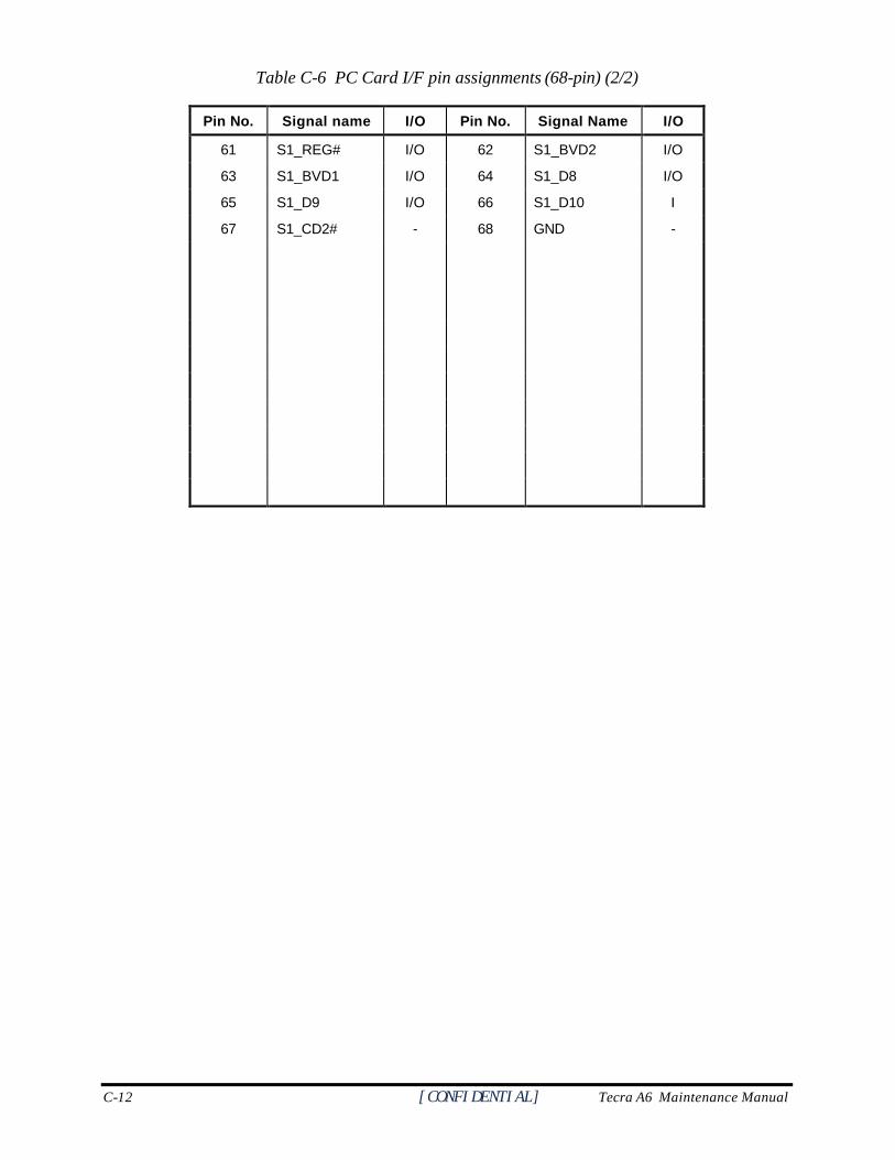
C-12 [CONFIDENTIAL] Tecra A6 Maintenance Manual
Table C-6 PC Card I/F pin assignments (68-pin) (2/2)
Pin No. Signal name I/O Pin No. Signal Name I/O
61 S1_REG# I/O 62 S1_BVD2 I/O
63 S1_BVD1 I/O 64 S1_D8 I/O
65 S1_D9 I/O 66 S1_D10 I
67 S1_CD2# - 68 GND -
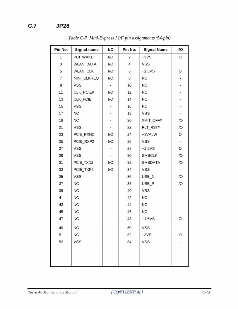
Tecra A6 Maintenance Manual [CONFIDENTIAL] C-13
C.7 JP28
Table C-7 Mini-Express I I/F pin assignments (54-pin)
Pin No. Signal name I/O Pin No. Signal Name I/O
1 PCI_WAKE I/O 2 +3VS O
3 WLAN_DATA I/O 4 VSS
5 WLAN_CLK I/O 6 +1.5VS O
7 MINI_CLKREQ I/O 8 NC -
9 VSS - 10 NC -
11 CLK_PCIE# I/O 12 NC -
13 CLK_PCIE I/O 14 NC -
15 VSS - 16 NC -
17 NC - 18 VSS -
19 NC - 20 XMIT_OFF# I/O
21 VSS - 22 PLT_RST# I/O
23 PCIE_RXN2 I/O 24 +3VALW O
25 PCIE_RXP2 I/O 26 VSS -
27 VSS - 28 +1.5VS O
29 VSS - 30 SMBCLK I/O
31 PCIE_TXN2 I/O 32 SMBDATA I/O
33 PCIE_TXP2 I/O 34 VSS -
35 VSS - 36 USB_N I/O
37 NC - 38 USB_P I/O
39 NC - 40 VSS -
41 NC - 42 NC -
43 NC - 44 NC -
45 NC - 46 NC -
47 NC - 48 +1.5VS O
49 NC - 50 VSS -
51 NC - 52 +3VS O
53 VSS - 54 VSS -
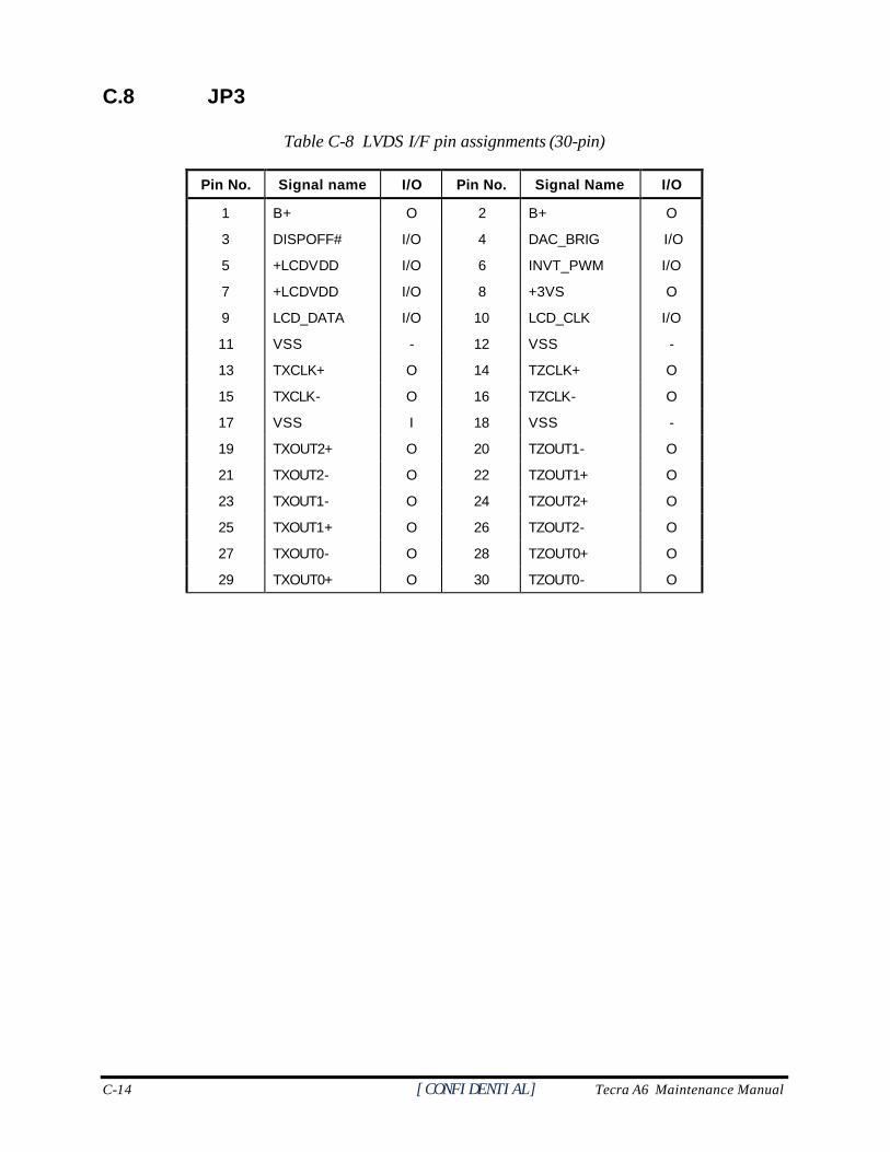
C-14 [CONFIDENTIAL] Tecra A6 Maintenance Manual
C.8 JP3
Table C-8 LVDS I/F pin assignments (30-pin)
Pin No. Signal name I/O Pin No. Signal Name I/O
1 B+ O 2 B+ O
3 DISPOFF# I/O 4 DAC_BRIG I/O
5 +LCDVDD I/O 6 INVT_PWM I/O
7 +LCDVDD I/O 8 +3VS O
9 LCD_DATA I/O 10 LCD_CLK I/O
11 VSS - 12 VSS -
13 TXCLK+ O 14 TZCLK+ O
15 TXCLK- O 16 TZCLK- O
17 VSS I 18 VSS -
19 TXOUT2+ O 20 TZOUT1- O
21 TXOUT2- O 22 TZOUT1+ O
23 TXOUT1- O 24 TZOUT2+ O
25 TXOUT1+ O 26 TZOUT2- O
27 TXOUT0- O 28 TZOUT0+ O
29 TXOUT0+ O 30 TZOUT0- O
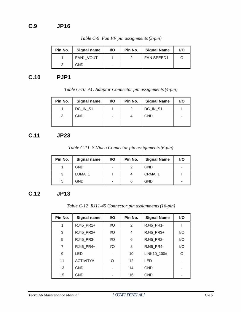
Tecra A6 Maintenance Manual [CONFIDENTIAL] C-15
C.9 JP16
Table C-9 Fan I/F pin assignments (3-pin)
Pin No. Signal name I/O Pin No. Signal Name I/O
1 FAN1_VOUT I 2 FAN-SPEED1 O
3 GND -
C.10 PJP1
Table C-10 AC Adaptor Connector pin assignments (4-pin)
Pin No. Signal name I/O Pin No. Signal Name I/O
1 DC_IN_S1 I 2 DC_IN_S1 I
3 GND - 4 GND -
C.11 JP23
Table C-11 S-Video Connector pin assignments (6-pin)
Pin No. Signal name I/O Pin No. Signal Name I/O
1 GND - 2 GND -
3 LUMA_1 I 4 CRMA_1 I
5 GND - 6 GND -
C.12 JP13
Table C-12 RJ11-45 Connector pin assignments (16-pin)
Pin No. Signal name I/O Pin No. Signal Name I/O
1 RJ45_PR1+ I/O 2 RJ45_PR1- I
3
5
7
9
11
RJ45_PR2+
RJ45_PR3-
RJ45_PR4+
LED
ACTIVITY#
I/O
I/O
I/O
-
O
4
6
8
10
12
RJ45_PR3+
RJ45_PR2-
RJ45_PR4-
LINK10_100#
LED
I/O
I/O
I/O
O
-
13 GND - 14 GND -
15 GND - 16 GND -

C-16 [CONFIDENTIAL] Tecra A6 Maintenance Manual
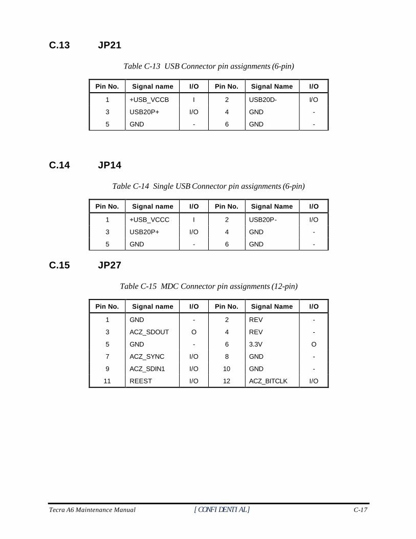
Tecra A6 Maintenance Manual [CONFIDENTIAL] C-17
C.13 JP21
Table C-13 USB Connector pin assignments (6-pin)
Pin No. Signal name I/O Pin No. Signal Name I/O
1 +USB_VCCB I 2 USB20D- I/O
3
5
USB20P+
GND
I/O
-
4
6
GND
GND
-
-
C.14 JP14
Table C-14 Single USB Connector pin assignments (6-pin)
Pin No. Signal name I/O Pin No. Signal Name I/O
1 +USB_VCCC I 2 USB20P- I/O
3 USB20P+ I/O 4 GND -
5 GND - 6 GND -
C.15 JP27
Table C-15 MDC Connector pin assignments (12-pin)
Pin No. Signal name I/O Pin No. Signal Name I/O
1 GND - 2 REV -
3 ACZ_SDOUT O 4 REV -
5 GND - 6 3.3V O
7 ACZ_SYNC I/O 8 GND -
9 ACZ_SDIN1 I/O 10 GND -
11 REEST I/O 12 ACZ_BITCLK I/O
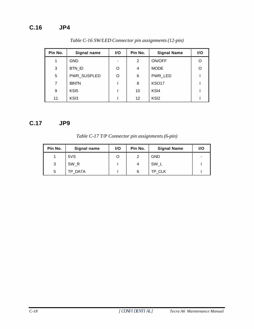
C-18 [CONFIDENTIAL] Tecra A6 Maintenance Manual
C.16 JP4
Table C-16 SW/LED Connector pin assignments (12-pin)
Pin No. Signal name I/O Pin No. Signal Name I/O
1 GND - 2 ON/OFF O
3
5
7
9
11
BTN_ID
PWR_SUSPLED
IBNTN
KSI5
KSI3
O
O
I
I
I
4
6
8
10
12
MODE
PWR_LED
KSO17
KSI4
KSI2
O
I
I
I
I
C.17 JP9
Table C-17 T/P Connector pin assignments (6-pin)
Pin No. Signal name I/O Pin No. Signal Name I/O
1 5VS O 2 GND -
3
5
SW_R
TP_DATA
I
I
4
6
SW_L
TP_CLK
I
I
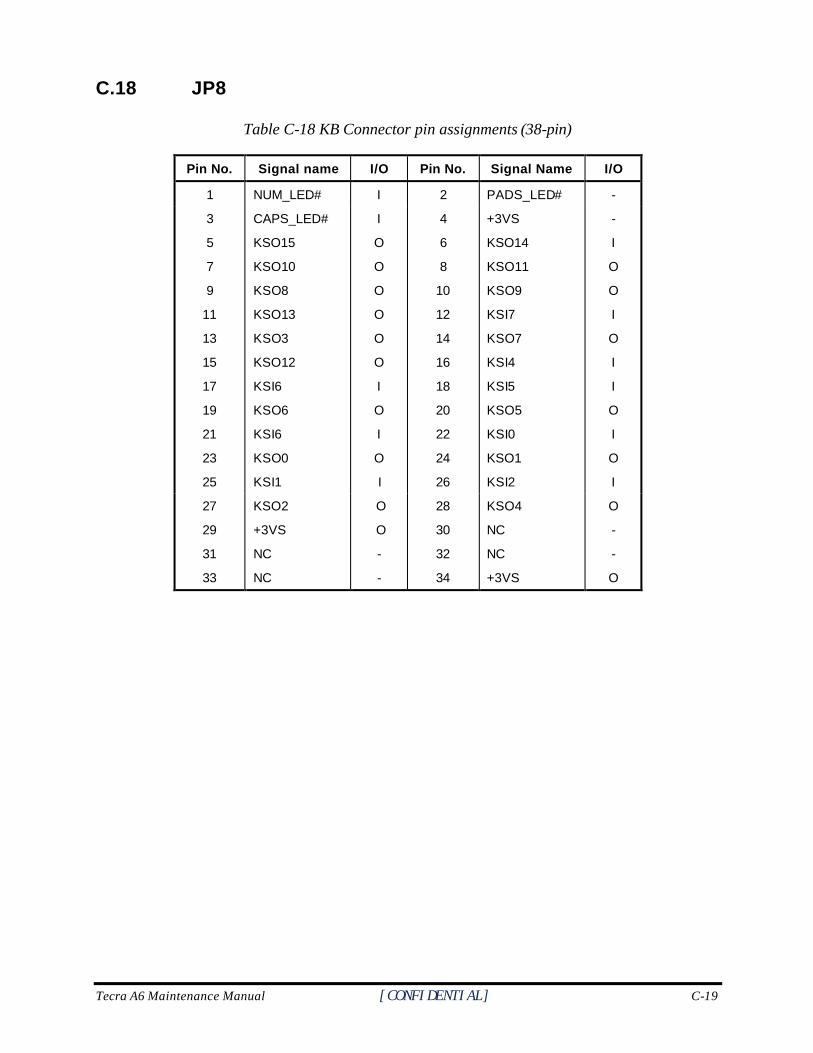
Tecra A6 Maintenance Manual [CONFIDENTIAL] C-19
C.18 JP8
Table C-18 KB Connector pin assignments (38-pin)
Pin No. Signal name I/O Pin No. Signal Name I/O
1 NUM_LED# I 2 PADS_LED# -
3
5
7
9
11
13
15
17
19
21
23
25
CAPS_LED#
KSO15
KSO10
KSO8
KSO13
KSO3
KSO12
KSI6
KSO6
KSI6
KSO0
KSI1
I
O
O
O
O
O
O
I
O
I
O
I
4
6
8
10
12
14
16
18
20
22
24
26
+3VS
KSO14
KSO11
KSO9
KSI7
KSO7
KSI4
KSI5
KSO5
KSI0
KSO1
KSI2
-
I
O
O
I
O
I
I
O
I
O
I
27
29
31
33
KSO2
+3VS
NC
NC
O
O
-
-
28
30
32
34
KSO4
NC
NC
+3VS
O
-
-
O
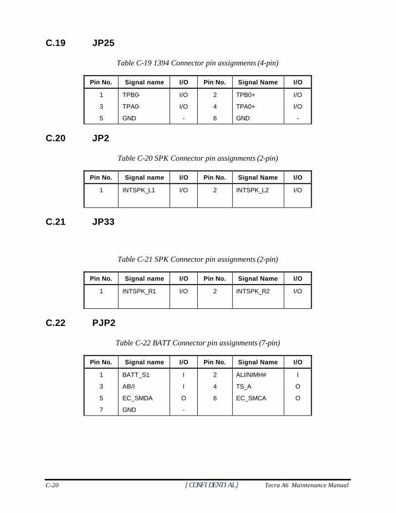
C-20 [CONFIDENTIAL] Tecra A6 Maintenance Manual
C.19 JP25
Table C-19 1394 Connector pin assignments (4-pin)
Pin No. Signal name I/O Pin No. Signal Name I/O
1 TPB0- I/O 2 TPB0+ I/O
3
5
TPA0-
GND
I/O
-
4
6
TPA0+
GND
I/O
-
C.20 JP2
Table C-20 SPK Connector pin assignments (2-pin)
Pin No. Signal name I/O Pin No. Signal Name I/O
1 INTSPK_L1 I/O 2 INTSPK_L2 I/O
C.21 JP33
Table C-21 SPK Connector pin assignments (2-pin)
Pin No. Signal name I/O Pin No. Signal Name I/O
1 INTSPK_R1 I/O 2 INTSPK_R2 I/O
C.22 PJP2
Table C-22 BATT Connector pin assignments (7-pin)
Pin No. Signal name I/O Pin No. Signal Name I/O
1 BATT_S1 I 2 ALI/NIMH# I
3
5
7
AB/I
EC_SMDA
GND
I
O
-
4
6
TS_A
EC_SMCA
O
O
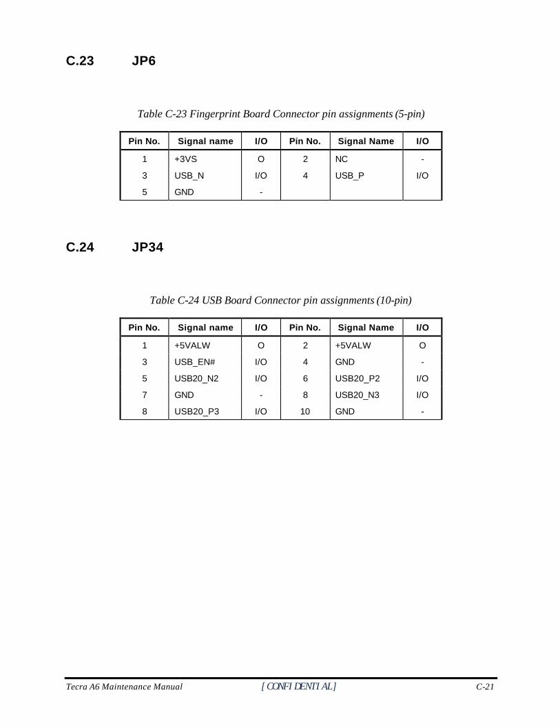
Tecra A6 Maintenance Manual [CONFIDENTIAL] C-21
C.23 JP6
Table C-23 Fingerprint Board Connector pin assignments (5-pin)
Pin No. Signal name I/O Pin No. Signal Name I/O
1 +3VS O 2 NC -
3 USB_N I/O 4 USB_P I/O
5 GND -
C.24 JP34
Table C-24 USB Board Connector pin assignments (10-pin)
Pin No. Signal name I/O Pin No. Signal Name I/O
1 +5VALW O 2 +5VALW O
3 USB_EN# I/O 4 GND -
5 USB20_N2 I/O 6 USB20_P2 I/O
7 GND - 8 USB20_N3 I/O
8 USB20_P3 I/O 10 GND -
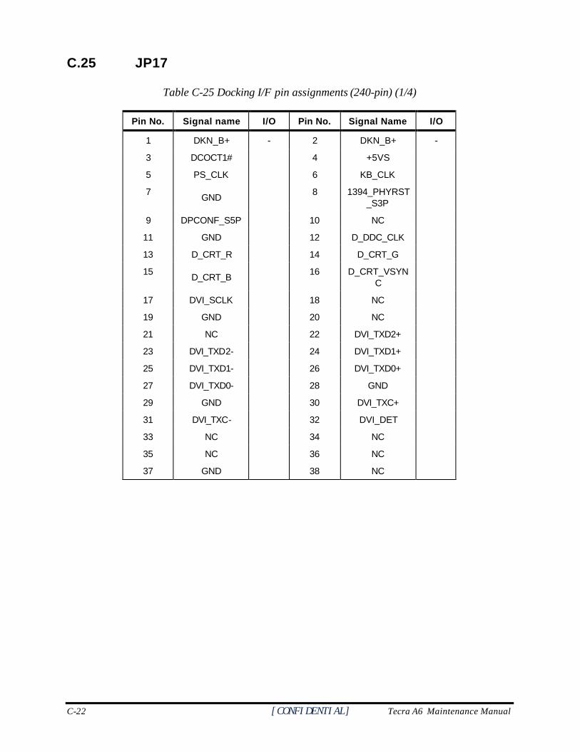
C-22 [CONFIDENTIAL] Tecra A6 Maintenance Manual
C.25 JP17
Table C-25 Docking I/F pin assignments (240-pin) (1/4)
Pin No. Signal name I/O Pin No. Signal Name I/O
1 DKN_B+ - 2 DKN_B+ -
3 DCOCT1# 4 +5VS
5 PS_CLK 6 KB_CLK
7 GND 8 1394_PHYRST
_S3P
9 DPCONF_S5P 10 NC
11 GND 12 D_DDC_CLK
13 D_CRT_R 14 D_CRT_G
15 D_CRT_B 16 D_CRT_VSYN
C
17 DVI_SCLK 18 NC
19 GND 20 NC
21 NC 22 DVI_TXD2+
23 DVI_TXD2- 24 DVI_TXD1+
25 DVI_TXD1- 26 DVI_TXD0+
27 DVI_TXD0- 28 GND
29 GND 30 DVI_TXC+
31 DVI_TXC- 32 DVI_DET
33 NC 34 NC
35 NC 36 NC
37 GND 38 NC
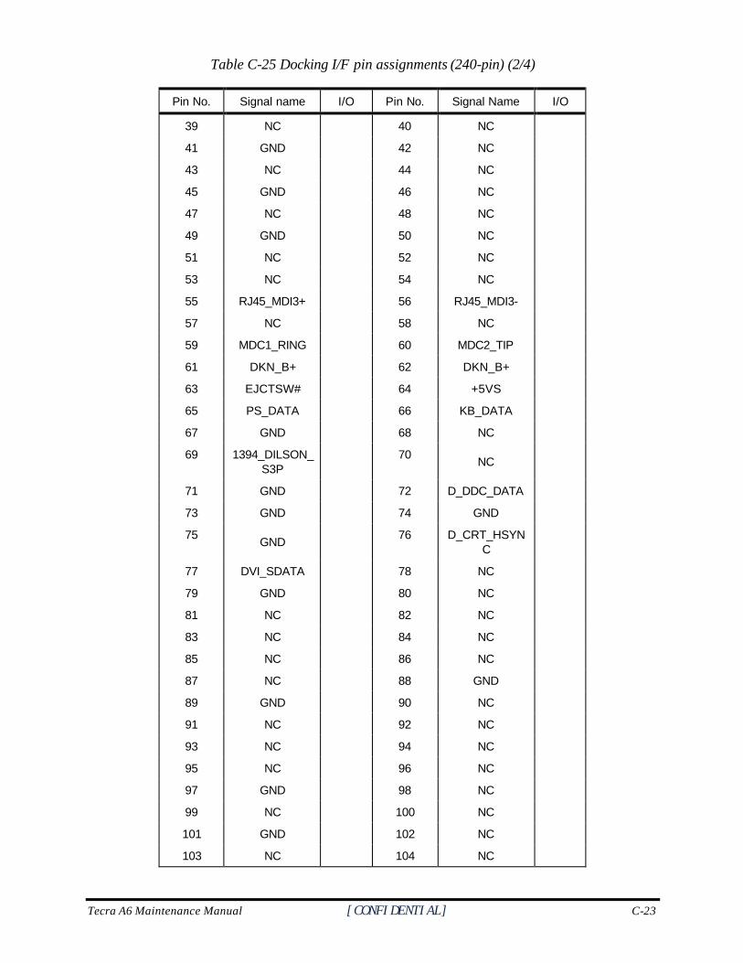
Tecra A6 Maintenance Manual [CONFIDENTIAL] C-23
Table C-25 Docking I/F pin assignments (240-pin) (2/4)
Pin No. Signal name I/O Pin No. Signal Name I/O
39 NC 40 NC
41 GND 42 NC
43 NC 44 NC
45 GND 46 NC
47 NC 48 NC
49 GND 50 NC
51 NC 52 NC
53 NC 54 NC
55 RJ45_MDI3+ 56 RJ45_MDI3-
57 NC 58 NC
59 MDC1_RING 60 MDC2_TIP
61 DKN_B+ 62 DKN_B+
63 EJCTSW# 64 +5VS
65 PS_DATA 66 KB_DATA
67 GND 68 NC
69 1394_DILSON_S3P
70 NC
71 GND 72 D_DDC_DATA
73 GND 74 GND
75 GND 76 D_CRT_HSYN
C
77 DVI_SDATA 78 NC
79 GND 80 NC
81 NC 82 NC
83 NC 84 NC
85 NC 86 NC
87 NC 88 GND
89 GND 90 NC
91 NC 92 NC
93 NC 94 NC
95 NC 96 NC
97 GND 98 NC
99 NC 100 NC
101 GND 102 NC
103 NC 104 NC
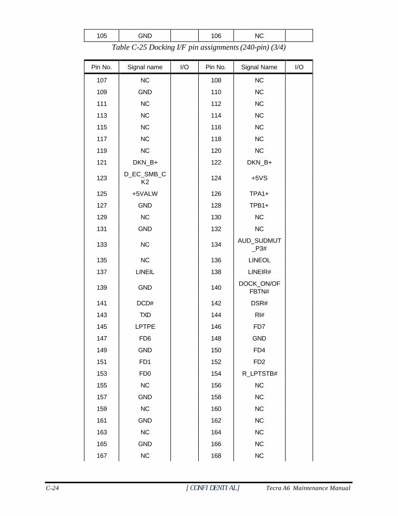
C-24 [CONFIDENTIAL] Tecra A6 Maintenance Manual
105 GND 106 NC
Table C-25 Docking I/F pin assignments (240-pin) (3/4)
Pin No. Signal name I/O Pin No. Signal Name I/O
107 NC 108 NC
109 GND 110 NC
111 NC 112 NC
113 NC 114 NC
115 NC 116 NC
117 NC 118 NC
119 NC 120 NC
121 DKN_B+ 122 DKN_B+
123 D_EC_SMB_CK2
124 +5VS
125 +5VALW 126 TPA1+
127 GND 128 TPB1+
129 NC 130 NC
131 GND 132 NC
133 NC 134
AUD_SUDMUT_P3#
135 NC 136 LINEOL
137 LINEIL 138 LINEIR#
139 GND 140
DOCK_ON/OFFBTN#
141 DCD# 142 DSR#
143 TXD 144 RI#
145 LPTPE 146 FD7
147 FD6 148 GND
149 GND 150 FD4
151 FD1 152 FD2
153 FD0 154 R_LPTSTB#
155 NC 156 NC
157 GND 158 NC
159 NC 160 NC
161 GND 162 NC
163 NC 164 NC
165 GND 166 NC
167 NC 168 NC
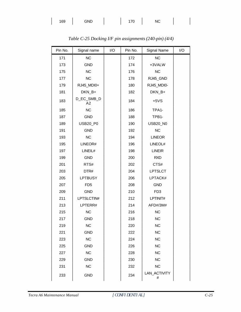
Tecra A6 Maintenance Manual [CONFIDENTIAL] C-25
169 GND 170 NC
Table C-25 Docking I/F pin assignments (240-pin) (4/4)
Pin No. Signal name I/O Pin No. Signal Name I/O
171 NC 172 NC
173 GND 174 +3VALW
175 NC 176 NC
177 NC 178 RJ45_GND
179 RJ45_MDI0+ 180 RJ45_MDI0-
181 DKN_B+ 182 DKN_B+
183 D_EC_SMB_DA2
184 +5VS
185 NC 186 TPA1-
187 GND 188 TPB1-
189 USB20_P0 190 USB20_N0
191 GND 192 NC
193 NC 194 LINEOR
195 LINEOR# 196 LINEOL#
197 LINEIL# 198 LINEIR
199 GND 200 RXD
201 RTS# 202 CTS#
203 DTR# 204 LPTSLCT
205 LPTBUSY 206 LPTACK#
207 FD5 208 GND
209 GND 210 FD3
211 LPTSLCTIN# 212 LPTINIT#
213 LPTERR# 214 AFD#/3M#
215 NC 216 NC
217 GND 218 NC
219 NC 220 NC
221 GND 222 NC
223 NC 224 NC
225 GND 226 NC
227 NC 228 NC
229 GND 230 NC
231 NC 232 NC
233 GND 234 LAN_ACTIVITY#

C-26 [CONFIDENTIAL] Tecra A6 Maintenance Manual
235 LAN_LINK# 236 DCOCT2#
237 NC 238 NC
239 RJ45_MDI1+ 240 RJ45_MDI1-
C.26 JP18
Table C-26 VGA/B I/F pin assignments (200-pin) (1/5)
Pin No. Signal name I/O Pin No. Signal Name I/O
1 B+ - 2 +1.8VS -
3 B+ - 4 +1.8VS
5 B+ - 6 +1.8VS
7 B+ - 8 +1.8VS
9 B+ - 10 +1.8VS
11 B+ - 12 +1.8VS
13 NC 14 +1.8VS
15 +1.5VS 16 +1.8VS
17 +1.5VS 18 +1.8VS
19 +1.5VS 20 +1.8VS
21 +1.5VS 22 +1.8VS
23 +1.5VS 24 +1.8VS
25 +1.5VS 26 +1.8VS
27 +1.5VS 28 +1.8VS
29 +1.5VS 30 +1.8VS
31 +2.5VS 32 +1.8VS
33 +2.5VS 34 +3VS
35 +2.5VS 36 +3VS
37 VGA_CLK 38 +3VS
39 VGA_DATA 40 +5VS
41 NC 42 NC
43 LVDSBC- 44 LVDSAC-
45 LVDSBC+ 46 LVDSAC+
47 GND 48 GND
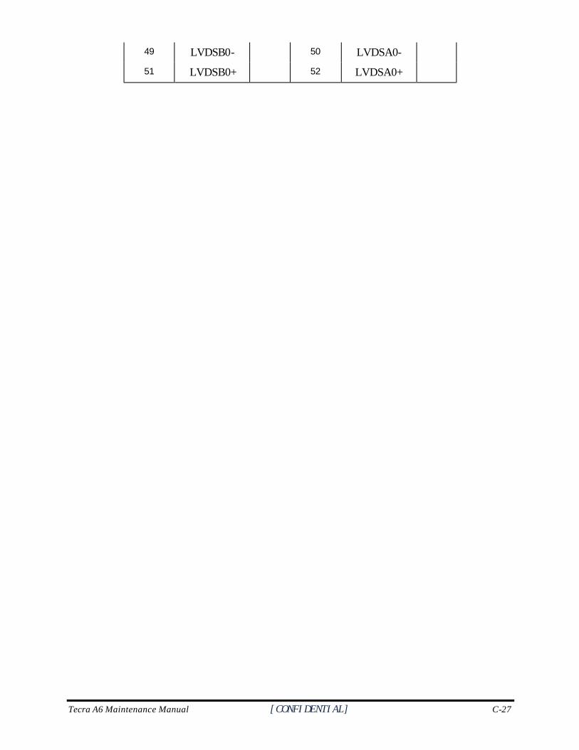
Tecra A6 Maintenance Manual [CONFIDENTIAL] C-27
49 LVDSB0- 50 LVDSA0-
51 LVDSB0+ 52 LVDSA0+
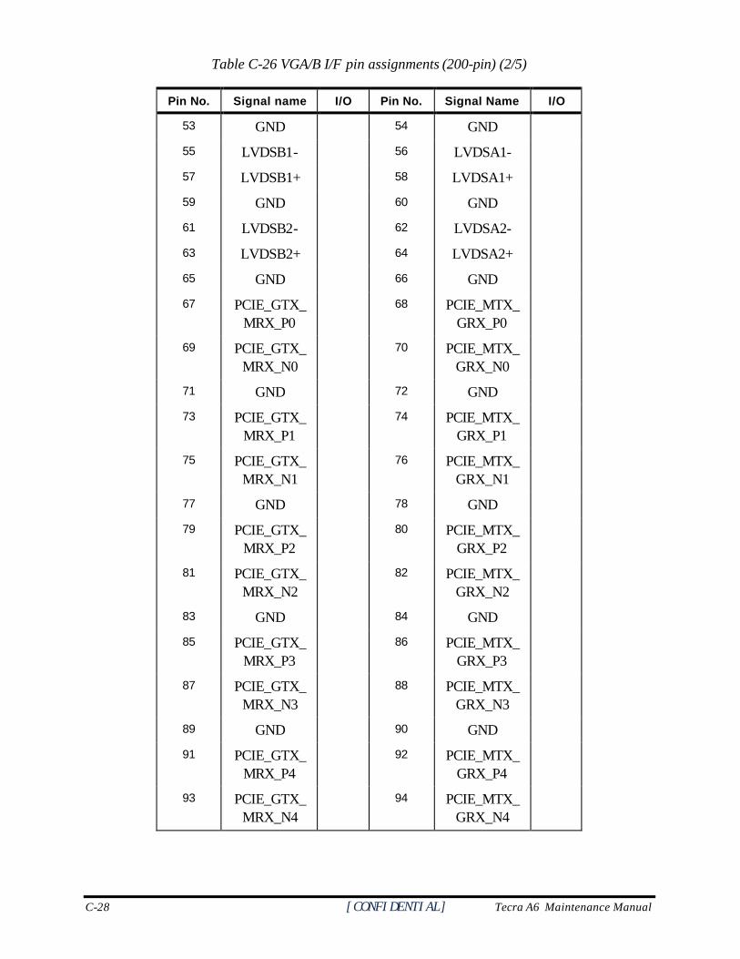
C-28 [CONFIDENTIAL] Tecra A6 Maintenance Manual
Table C-26 VGA/B I/F pin assignments (200-pin) (2/5)
Pin No. Signal name I/O Pin No. Signal Name I/O
53 GND 54 GND
55 LVDSB1- 56 LVDSA1-
57 LVDSB1+ 58 LVDSA1+
59 GND 60 GND
61 LVDSB2- 62 LVDSA2-
63 LVDSB2+ 64 LVDSA2+
65 GND 66 GND
67 PCIE_GTX_MRX_P0
68 PCIE_MTX_GRX_P0
69 PCIE_GTX_MRX_N0
70 PCIE_MTX_GRX_N0
71 GND 72 GND
73 PCIE_GTX_MRX_P1
74 PCIE_MTX_GRX_P1
75 PCIE_GTX_MRX_N1
76 PCIE_MTX_GRX_N1
77 GND 78 GND
79 PCIE_GTX_MRX_P2
80 PCIE_MTX_GRX_P2
81 PCIE_GTX_MRX_N2
82 PCIE_MTX_GRX_N2
83 GND 84 GND
85 PCIE_GTX_MRX_P3
86 PCIE_MTX_GRX_P3
87 PCIE_GTX_MRX_N3
88 PCIE_MTX_GRX_N3
89 GND 90 GND
91 PCIE_GTX_MRX_P4
92 PCIE_MTX_GRX_P4
93 PCIE_GTX_MRX_N4
94 PCIE_MTX_GRX_N4
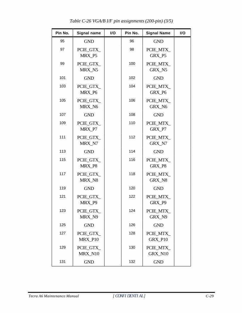
Tecra A6 Maintenance Manual [CONFIDENTIAL] C-29
Table C-26 VGA/B I/F pin assignments (200-pin) (3/5)
Pin No. Signal name I/O Pin No. Signal Name I/O
95 GND 96 GND
97 PCIE_GTX_MRX_P5
98 PCIE_MTX_GRX_P5
99 PCIE_GTX_MRX_N5
100 PCIE_MTX_GRX_N5
101 GND 102 GND
103 PCIE_GTX_MRX_P6
104 PCIE_MTX_GRX_P6
105 PCIE_GTX_MRX_N6
106 PCIE_MTX_GRX_N6
107 GND 108 GND
109 PCIE_GTX_MRX_P7
110 PCIE_MTX_GRX_P7
111 PCIE_GTX_MRX_N7
112 PCIE_MTX_GRX_N7
113 GND 114 GND
115 PCIE_GTX_MRX_P8
116 PCIE_MTX_GRX_P8
117 PCIE_GTX_MRX_N8
118 PCIE_MTX_GRX_N8
119 GND 120 GND
121 PCIE_GTX_MRX_P9
122 PCIE_MTX_GRX_P9
123 PCIE_GTX_MRX_N9
124 PCIE_MTX_GRX_N9
125 GND 126 GND
127 PCIE_GTX_MRX_P10
128 PCIE_MTX_GRX_P10
129 PCIE_GTX_MRX_N10
130 PCIE_MTX_GRX_N10
131 GND 132 GND
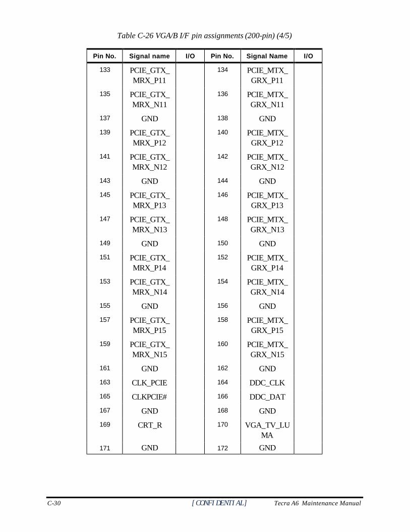
C-30 [CONFIDENTIAL] Tecra A6 Maintenance Manual
Table C-26 VGA/B I/F pin assignments (200-pin) (4/5)
Pin No. Signal name I/O Pin No. Signal Name I/O
133 PCIE_GTX_MRX_P11
134 PCIE_MTX_GRX_P11
135 PCIE_GTX_MRX_N11
136 PCIE_MTX_GRX_N11
137 GND 138 GND
139 PCIE_GTX_MRX_P12
140 PCIE_MTX_GRX_P12
141 PCIE_GTX_MRX_N12
142 PCIE_MTX_GRX_N12
143 GND 144 GND
145 PCIE_GTX_MRX_P13
146 PCIE_MTX_GRX_P13
147 PCIE_GTX_MRX_N13
148 PCIE_MTX_GRX_N13
149 GND 150 GND
151 PCIE_GTX_MRX_P14
152 PCIE_MTX_GRX_P14
153 PCIE_GTX_MRX_N14
154 PCIE_MTX_GRX_N14
155 GND 156 GND
157 PCIE_GTX_MRX_P15
158 PCIE_MTX_GRX_P15
159 PCIE_GTX_MRX_N15
160 PCIE_MTX_GRX_N15
161 GND 162 GND
163 CLK_PCIE 164 DDC_CLK
165 CLKPCIE# 166 DDC_DAT
167 GND 168 GND
169 CRT_R 170 VGA_TV_LUMA
171 GND 172 GND
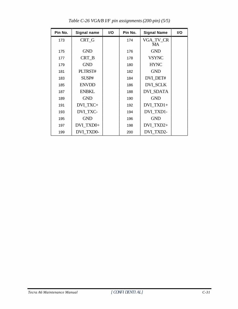
Tecra A6 Maintenance Manual [CONFIDENTIAL] C-31
Table C-26 VGA/B I/F pin assignments (200-pin) (5/5)
Pin No. Signal name I/O Pin No. Signal Name I/O
173 CRT_G 174 VGA_TV_CRMA
175 GND 176 GND
177 CRT_B 178 VSYNC
179 GND 180 HYNC
181 PLTRST# 182 GND
183 SUSP# 184 DVI_DET#
185 ENVDD 186 DVI_SCLK
187 ENBKL 188 DVI_SDATA
189 GND 190 GND
191 DVI_TXC+ 192 DVI_TXD1+
193 DVI_TXC- 194 DVI_TXD1-
195 GND 196 GND
197 DVI_TXD0+ 198 DVI_TXD2+
199 DVI_TXD0- 200 DVI_TXD2-

C-32 [CONFIDENTIAL] Tecra A6 Maintenance Manual
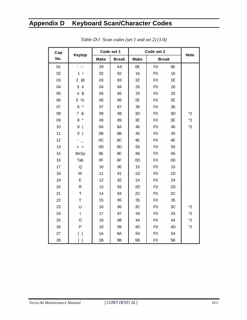
Tecra A6 Maintenance Manual [CONFIDENTIAL] D-1
Appendix D
Appendix D Keyboard Scan/Character Codes
Table D-1 Scan codes (set 1 and set 2) (1/4)
Code set 1 Code set 2 Cap
No. Keytop
Make Break Make Break Note
01 ‘ ~ 29 A9 0E F0 0E
02 1 ! 02 82 16 F0 16
03 2 @ 03 83 1E F0 1E
04 3 # 04 84 26 F0 26
05 4 $ 05 85 25 F0 25
06 5 % 06 86 2E F0 2E
07 6 ̂ 07 87 36 F0 36
08 7 & 08 88 3D F0 3D *2
09 8 * 09 89 3E F0 3E *2
10 9 ( 0A 8A 46 F0 46 *2
11 0 ) 0B 8B 45 F0 45
12 - _ 0C 8C 4E F0 4E
13 = + 0D 8D 55 F0 55
15 BkSp 0E 8E 66 F0 66
16 Tab 0F 8F 0D F0 0D
17 Q 10 90 15 F0 15
18 W 11 91 1D F0 1D
19 E 12 92 24 F0 24
20 R 13 93 2D F0 2D
21 T 14 94 2C F0 2C
22 Y 15 95 35 F0 35
23 U 16 96 3C F0 3C *2
24 I 17 97 43 F0 43 *2
25 O 18 98 44 F0 44 *2
26 P 19 99 4D F0 4D *2
27 [ { 1A 9A 54 F0 54
28 ] } 1B 9B 5B F0 5B
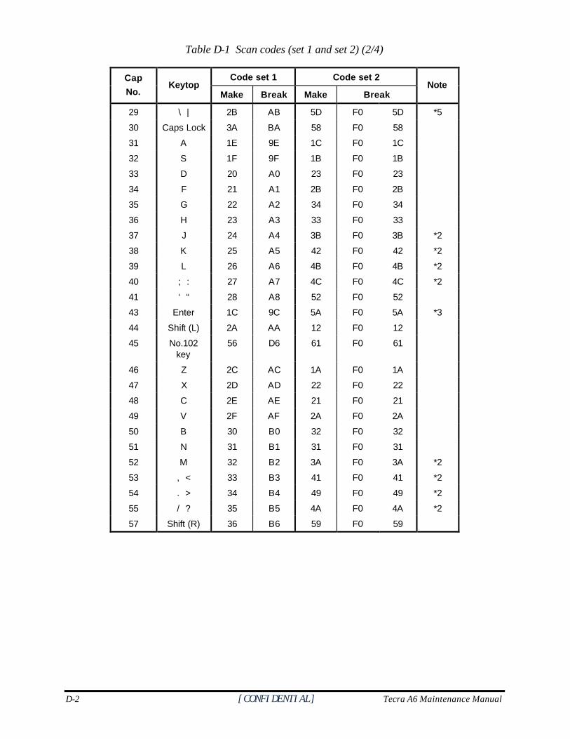
D-2 [CONFIDENTIAL] Tecra A6 Maintenance Manual
Table D-1 Scan codes (set 1 and set 2) (2/4)
Code set 1 Code set 2 Cap
No. Keytop
Make Break Make Break Note
29 \ | 2B AB 5D F0 5D *5
30 Caps Lock 3A BA 58 F0 58
31 A 1E 9E 1C F0 1C
32 S 1F 9F 1B F0 1B
33 D 20 A0 23 F0 23
34 F 21 A1 2B F0 2B
35 G 22 A2 34 F0 34
36 H 23 A3 33 F0 33
37 J 24 A4 3B F0 3B *2
38 K 25 A5 42 F0 42 *2
39 L 26 A6 4B F0 4B *2
40 ; : 27 A7 4C F0 4C *2
41 ‘ “ 28 A8 52 F0 52
43 Enter 1C 9C 5A F0 5A *3
44 Shift (L) 2A AA 12 F0 12
45 No.102 key
56 D6 61 F0 61
46 Z 2C AC 1A F0 1A
47 X 2D AD 22 F0 22
48 C 2E AE 21 F0 21
49 V 2F AF 2A F0 2A
50 B 30 B0 32 F0 32
51 N 31 B1 31 F0 31
52 M 32 B2 3A F0 3A *2
53 , < 33 B3 41 F0 41 *2
54 . > 34 B4 49 F0 49 *2
55 / ? 35 B5 4A F0 4A *2
57 Shift (R) 36 B6 59 F0 59
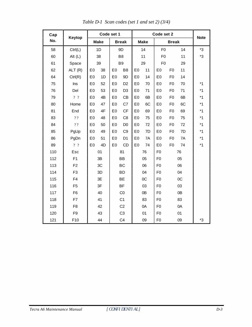
Tecra A6 Maintenance Manual [CONFIDENTIAL] D-3
Table D-1 Scan codes (set 1 and set 2) (3/4)
Code set 1 Code set 2 Cap No.
Keytop Make Break Make Break
Note
58 Ctrl(L) 1D 9D 14 F0 14 *3
60 Alt (L) 38 B8 11 F0 11 *3
61 Space 39 B9 29 F0 29
62 ALT (R) E0 38 E0 B8 E0 11 E0 F0 11
64 Ctrl(R) E0 1D E0 9D E0 14 E0 F0 14
75 Ins E0 52 E0 D2 E0 70 E0 F0 70 *1
76 Del E0 53 E0 D3 E0 71 E0 F0 71 *1
79 ? ? E0 4B E0 CB E0 6B E0 F0 6B *1
80 Home E0 47 E0 C7 E0 6C E0 F0 6C *1
81 End E0 4F E0 CF E0 69 E0 F0 69 *1
83 ? ? E0 48 E0 C8 E0 75 E0 F0 75 *1
84 ? ? E0 50 E0 D0 E0 72 E0 F0 72 *1
85 PgUp E0 49 E0 C9 E0 7D E0 F0 7D *1
86 PgDn E0 51 E0 D1 E0 7A E0 F0 7A *1
89 ? ? E0 4D E0 CD E0 74 E0 F0 74 *1
110 Esc 01 81 76 F0 76
112 F1 3B BB 05 F0 05
113 F2 3C BC 06 F0 06
114 F3 3D BD 04 F0 04
115 F4 3E BE 0C F0 0C
116 F5 3F BF 03 F0 03
117 F6 40 C0 0B F0 0B
118 F7 41 C1 83 F0 83
119 F8 42 C2 0A F0 0A
120 F9 43 C3 01 F0 01
121 F10 44 C4 09 F0 09 *3
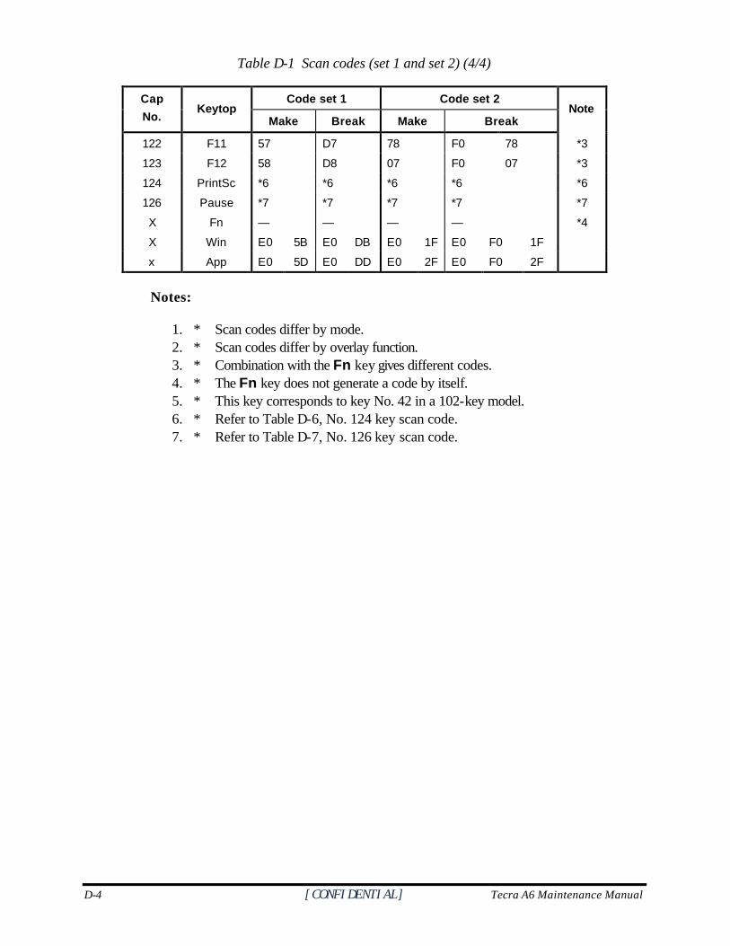
D-4 [CONFIDENTIAL] Tecra A6 Maintenance Manual
Table D-1 Scan codes (set 1 and set 2) (4/4)
Code set 1 Code set 2 Cap
No. Keytop
Make Break Make Break Note
122 F11 57 D7 78 F0 78 *3
123 F12 58 D8 07 F0 07 *3
124 PrintSc *6 *6 *6 *6 *6
126 Pause *7 *7 *7 *7 *7
X Fn — — — — *4
X Win E0 5B E0 DB E0 1F E0 F0 1F
x App E0 5D E0 DD E0 2F E0 F0 2F
Notes:
1. * Scan codes differ by mode. 2. * Scan codes differ by overlay function. 3. * Combination with the Fn key gives different codes. 4. * The Fn key does not generate a code by itself. 5. * This key corresponds to key No. 42 in a 102-key model. 6. * Refer to Table D-6, No. 124 key scan code. 7. * Refer to Table D-7, No. 126 key scan code.
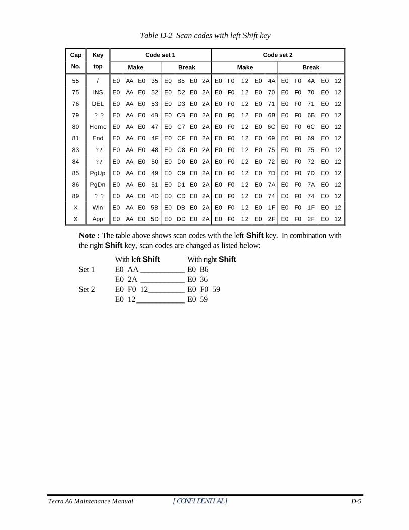
Tecra A6 Maintenance Manual [CONFIDENTIAL] D-5
Table D-2 Scan codes with left Shift key
Code set 1 Code set 2 Cap
No.
Key
top Make Break Make Break
55 / E0 AA E0 35 E0 B5 E0 2A E0 F0 12 E0 4A E0 F0 4A E0 12
75 INS E0 AA E0 52 E0 D2 E0 2A E0 F0 12 E0 70 E0 F0 70 E0 12
76 DEL E0 AA E0 53 E0 D3 E0 2A E0 F0 12 E0 71 E0 F0 71 E0 12
79 ? ? E0 AA E0 4B E0 CB E0 2A E0 F0 12 E0 6B E0 F0 6B E0 12
80 Home E0 AA E0 47 E0 C7 E0 2A E0 F0 12 E0 6C E0 F0 6C E0 12
81 End E0 AA E0 4F E0 CF E0 2A E0 F0 12 E0 69 E0 F0 69 E0 12
83 ? ? E0 AA E0 48 E0 C8 E0 2A E0 F0 12 E0 75 E0 F0 75 E0 12
84 ? ? E0 AA E0 50 E0 D0 E0 2A E0 F0 12 E0 72 E0 F0 72 E0 12
85 PgUp E0 AA E0 49 E0 C9 E0 2A E0 F0 12 E0 7D E0 F0 7D E0 12
86 PgDn E0 AA E0 51 E0 D1 E0 2A E0 F0 12 E0 7A E0 F0 7A E0 12
89 ? ? E0 AA E0 4D E0 CD E0 2A E0 F0 12 E0 74 E0 F0 74 E0 12
X Win E0 AA E0 5B E0 DB E0 2A E0 F0 12 E0 1F E0 F0 1F E0 12
X App E0 AA E0 5D E0 DD E0 2A E0 F0 12 E0 2F E0 F0 2F E0 12
Note : The table above shows scan codes with the left Shift key. In combination with the right Shift key, scan codes are changed as listed below:
With left Shift With right Shift Set 1 E0 AA ___________ E0 B6 E0 2A ___________ E0 36 Set 2 E0 F0 12_________ E0 F0 59 E0 12____________ E0 59
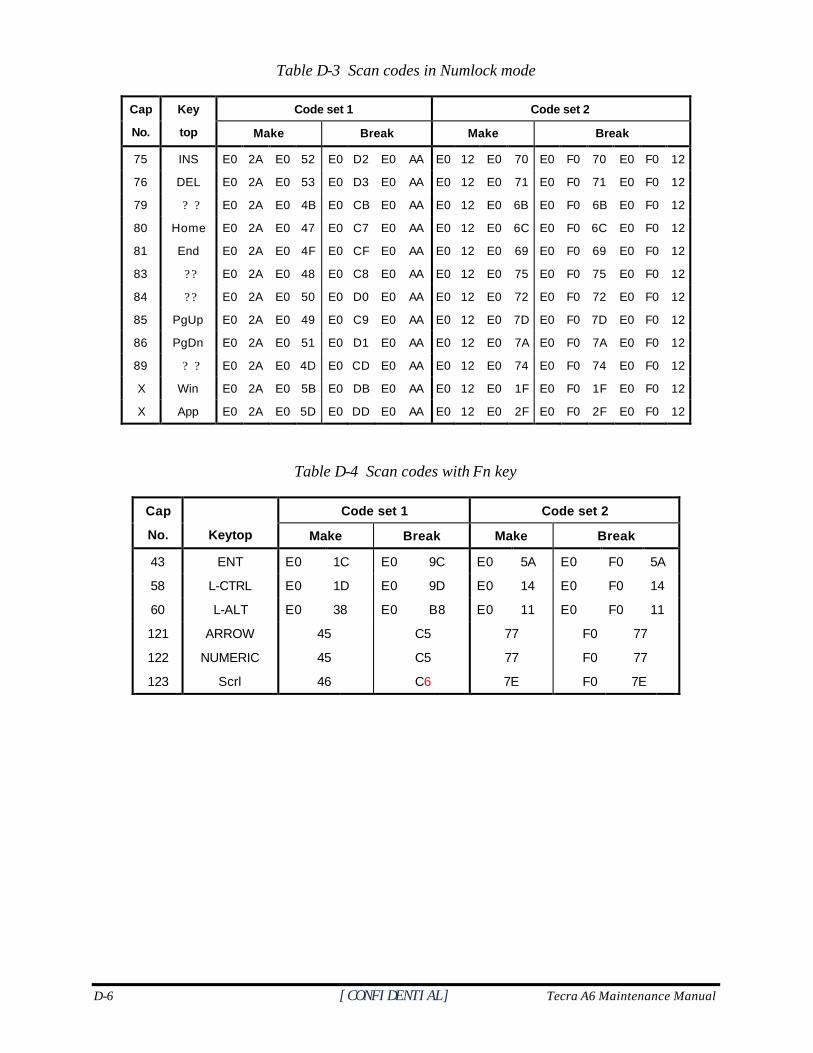
D-6 [CONFIDENTIAL] Tecra A6 Maintenance Manual
Table D-3 Scan codes in Numlock mode
Code set 1 Code set 2 Cap
No.
Key
top Make Break Make Break
75 INS E0 2A E0 52 E0 D2 E0 AA E0 12 E0 70 E0 F0 70 E0 F0 12
76 DEL E0 2A E0 53 E0 D3 E0 AA E0 12 E0 71 E0 F0 71 E0 F0 12
79 ? ? E0 2A E0 4B E0 CB E0 AA E0 12 E0 6B E0 F0 6B E0 F0 12
80 Home E0 2A E0 47 E0 C7 E0 AA E0 12 E0 6C E0 F0 6C E0 F0 12
81 End E0 2A E0 4F E0 CF E0 AA E0 12 E0 69 E0 F0 69 E0 F0 12
83 ? ? E0 2A E0 48 E0 C8 E0 AA E0 12 E0 75 E0 F0 75 E0 F0 12
84 ? ? E0 2A E0 50 E0 D0 E0 AA E0 12 E0 72 E0 F0 72 E0 F0 12
85 PgUp E0 2A E0 49 E0 C9 E0 AA E0 12 E0 7D E0 F0 7D E0 F0 12
86 PgDn E0 2A E0 51 E0 D1 E0 AA E0 12 E0 7A E0 F0 7A E0 F0 12
89 ? ? E0 2A E0 4D E0 CD E0 AA E0 12 E0 74 E0 F0 74 E0 F0 12
X Win E0 2A E0 5B E0 DB E0 AA E0 12 E0 1F E0 F0 1F E0 F0 12
X App E0 2A E0 5D E0 DD E0 AA E0 12 E0 2F E0 F0 2F E0 F0 12
Table D-4 Scan codes with Fn key
Code set 1 Code set 2 Cap
No.
Keytop Make Break Make Break
43 ENT E0 1C E0 9C E0 5A E0 F0 5A
58 L-CTRL E0 1D E0 9D E0 14 E0 F0 14
60 L-ALT E0 38 E0 B8 E0 11 E0 F0 11
121 ARROW 45 C5 77 F0 77
122 NUMERIC 45 C5 77 F0 77
123 Scrl 46 C6 7E F0 7E
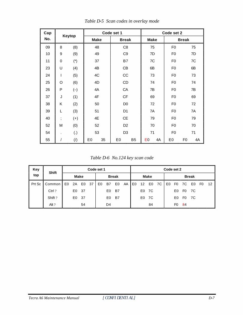
Tecra A6 Maintenance Manual [CONFIDENTIAL] D-7
Table D-5 Scan codes in overlay mode
Code set 1 Code set 2 Cap
No. Keytop
Make Break Make Break
09 8 (8) 48 C8 75 F0 75
10 9 (9) 49 C9 7D F0 7D
11 0 (*) 37 B7 7C F0 7C
23 U (4) 4B CB 6B F0 6B
24 I (5) 4C CC 73 F0 73
25 O (6) 4D CD 74 F0 74
26 P (–) 4A CA 7B F0 7B
37 J (1) 4F CF 69 F0 69
38 K (2) 50 D0 72 F0 72
39 L (3) 51 D1 7A F0 7A
40 ; (+) 4E CE 79 F0 79
52 M (0) 52 D2 70 F0 70
54 . (.) 53 D3 71 F0 71
55 / (/) E0 35 E0 B5 E0 4A E0 F0 4A
Table D-6 No.124 key scan code
Code set 1 Code set 2 Key
top Shift
Make Break Make Break
Prt Sc Common E0 2A E0 37 E0 B7 E0 AA E0 12 E0 7C E0 F0 7C E0 F0 12
Ctrl ? E0 37 E0 B7 E0 7C E0 F0 7C
Shift ? E0 37 E0 B7 E0 7C E0 F0 7C
Alt ? 54 D4 84 F0 84
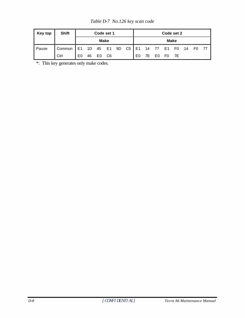
D-8 [CONFIDENTIAL] Tecra A6 Maintenance Manual
Table D-7 No.126 key scan code
Code set 1 Code set 2 Key top Shift
Make Make
Pause Common E1 1D 45 E1 9D C5 E1 14 77 E1 F0 14 F0 77
Ctrl E0 46 E0 C6 E0 7E E0 F0 7E
*: This key generates only make codes.
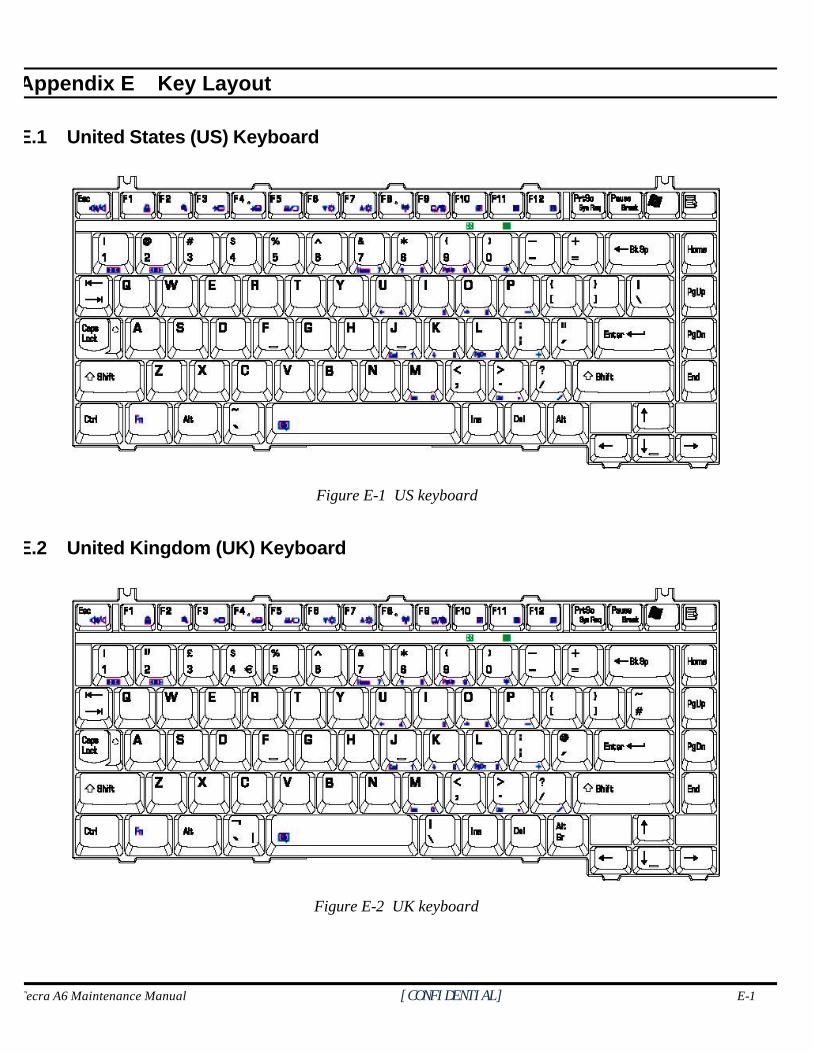
Tecra A6 Maintenance Manual [CONFIDENTIAL] E-1
Appendix E
Appendix E Key Layout
E.1 United States (US) Keyboard
Figure E-1 US keyboard
E.2 United Kingdom (UK) Keyboard
Figure E-2 UK keyboard
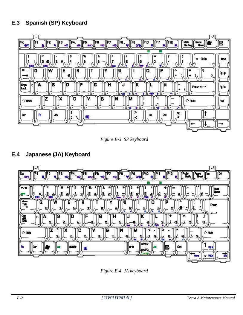
E-2 [CONFIDENTIAL] Tecra A Maintenance Manual
E.3 Spanish (SP) Keyboard
Figure E-3 SP keyboard
E.4 Japanese (JA) Keyboard
Figure E-4 JA keyboard
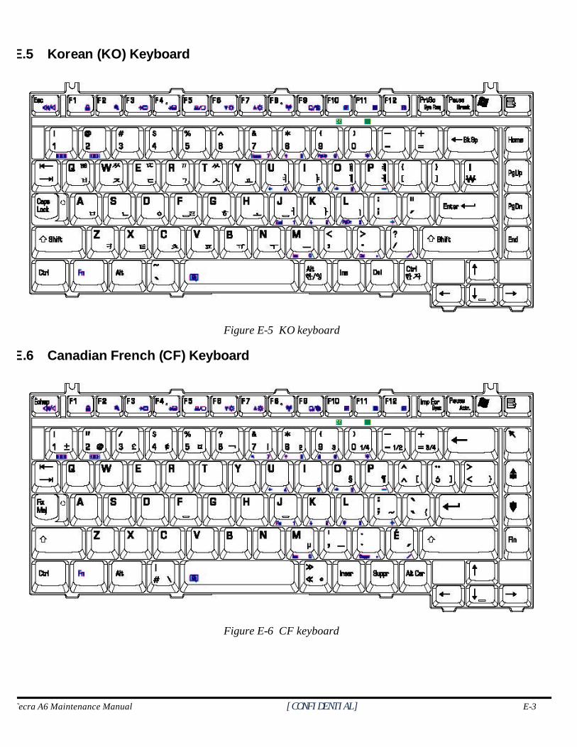
Tecra A6 Maintenance Manual [CONFIDENTIAL] E-3
E.5 Korean (KO) Keyboard
Figure E-5 KO keyboard
E.6 Canadian French (CF) Keyboard
Figure E-6 CF keyboard
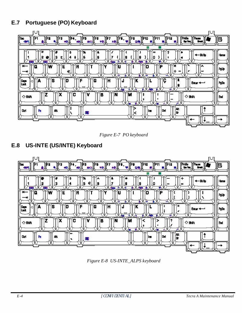
E-4 [CONFIDENTIAL] Tecra A Maintenance Manual
E.7 Portuguese (PO) Keyboard
Figure E-7 PO keyboard
E.8 US-INTE (US/INTE) Keyboard
Figure E-8 US-INTE_ALPS keyboard
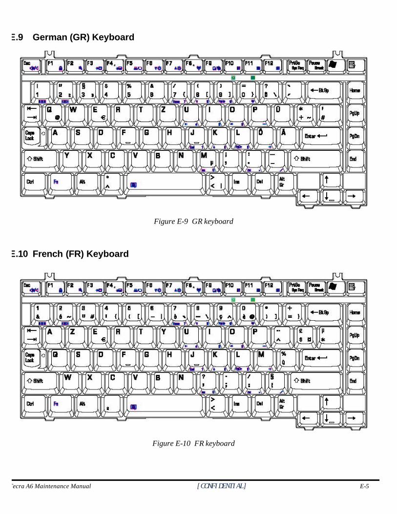
Tecra A6 Maintenance Manual [CONFIDENTIAL] E-5
E.9 German (GR) Keyboard
Figure E-9 GR keyboard
E.10 French (FR) Keyboard
Figure E-10 FR keyboard
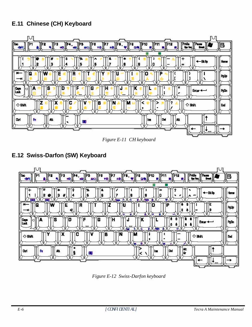
E-6 [CONFIDENTIAL] Tecra A Maintenance Manual
E.11 Chinese (CH) Keyboard
Figure E-11 CH keyboard
E.12 Swiss-Darfon (SW) Keyboard
Figure E-12 Swiss-Darfon keyboard
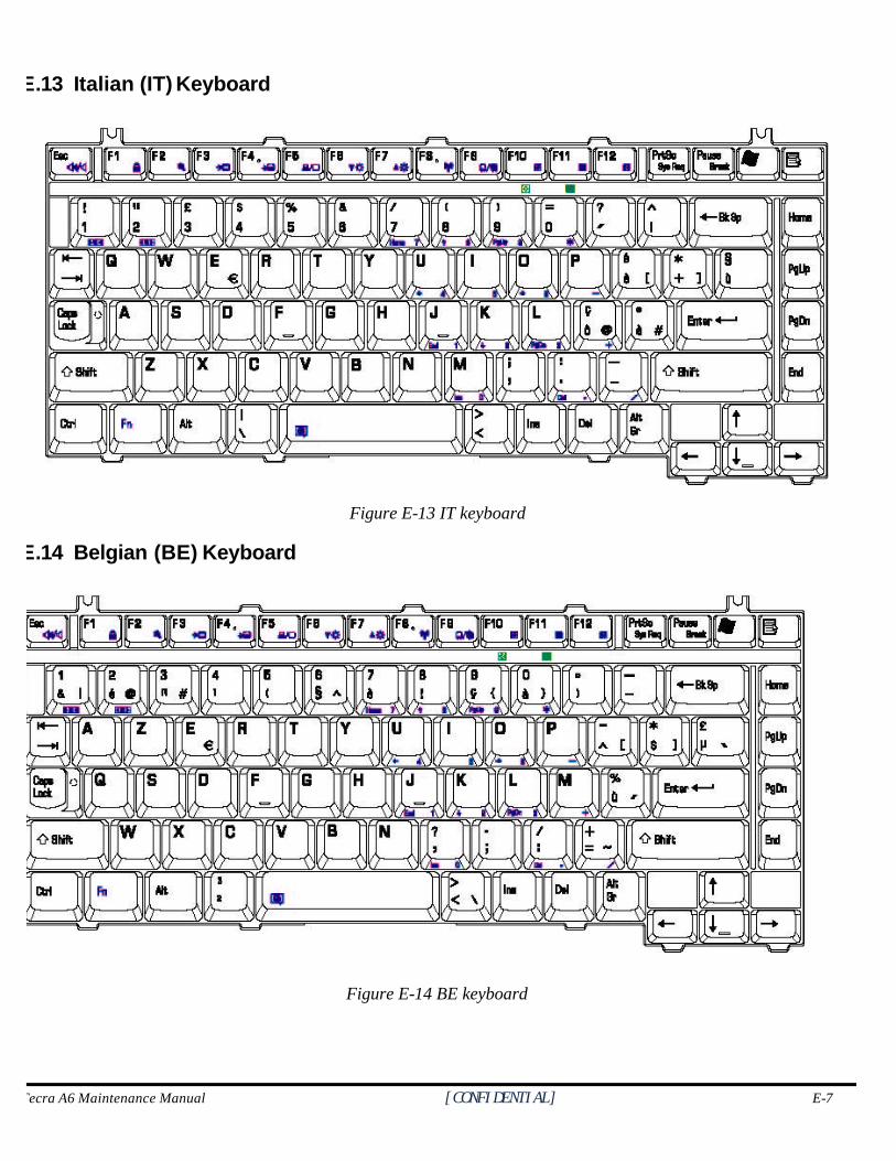
Tecra A6 Maintenance Manual [CONFIDENTIAL] E-7
E.13 Italian (IT) Keyboard
Figure E-13 IT keyboard
E.14 Belgian (BE) Keyboard
Figure E-14 BE keyboard
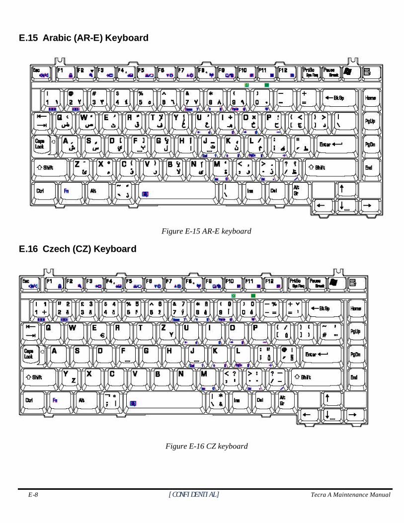
E-8 [CONFIDENTIAL] Tecra A Maintenance Manual
E.15 Arabic (AR-E) Keyboard
Figure E-15 AR-E keyboard
E.16 Czech (CZ) Keyboard
Figure E-16 CZ keyboard
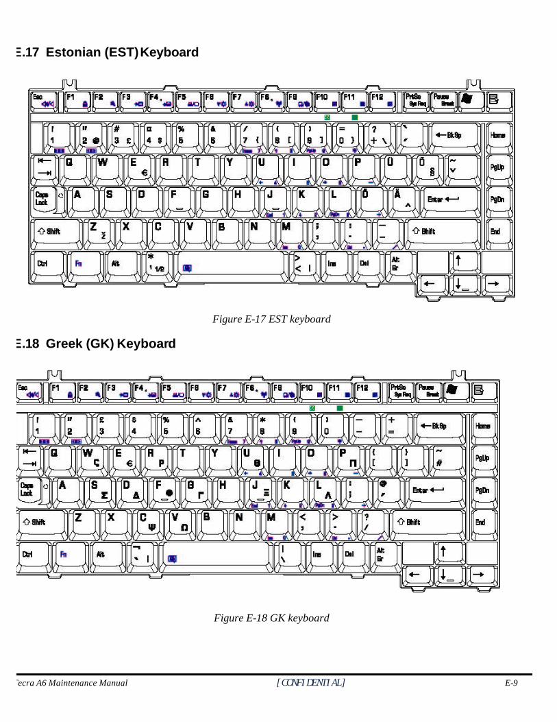
Tecra A6 Maintenance Manual [CONFIDENTIAL] E-9
E.17 Estonian (EST) Keyboard
Figure E-17 EST keyboard
E.18 Greek (GK) Keyboard
Figure E-18 GK keyboard
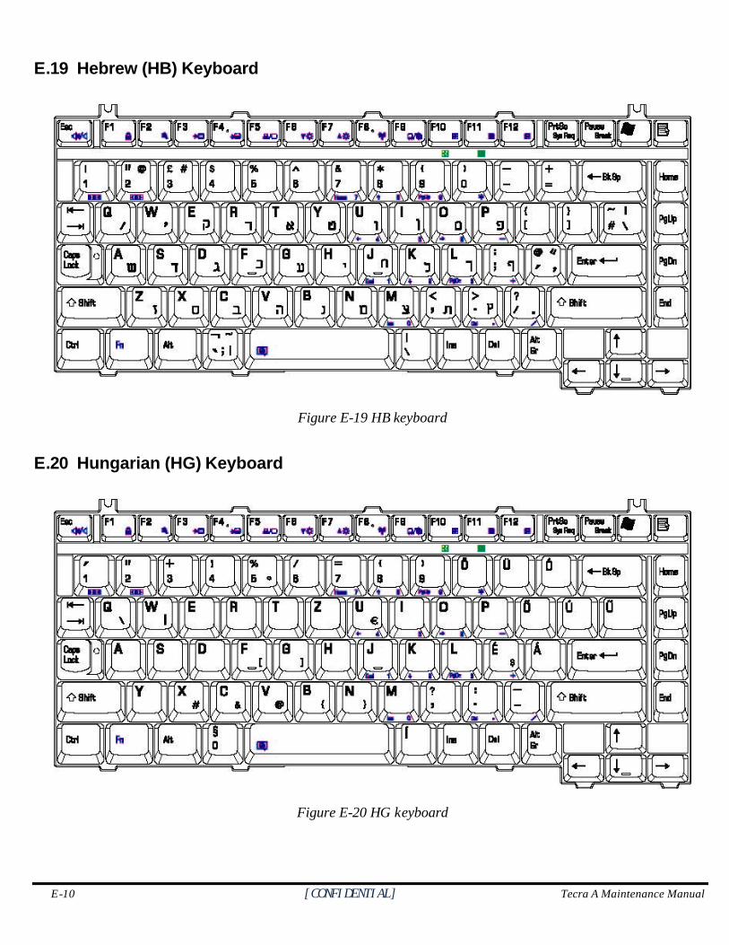
E-10 [CONFIDENTIAL] Tecra A Maintenance Manual
E.19 Hebrew (HB) Keyboard
Figure E-19 HB keyboard
E.20 Hungarian (HG) Keyboard
Figure E-20 HG keyboard
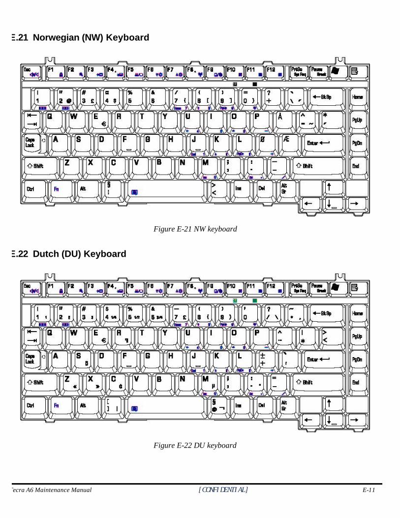
Tecra A6 Maintenance Manual [CONFIDENTIAL] E-11
E.21 Norwegian (NW) Keyboard
Figure E-21 NW keyboard
E.22 Dutch (DU) Keyboard
Figure E-22 DU keyboard
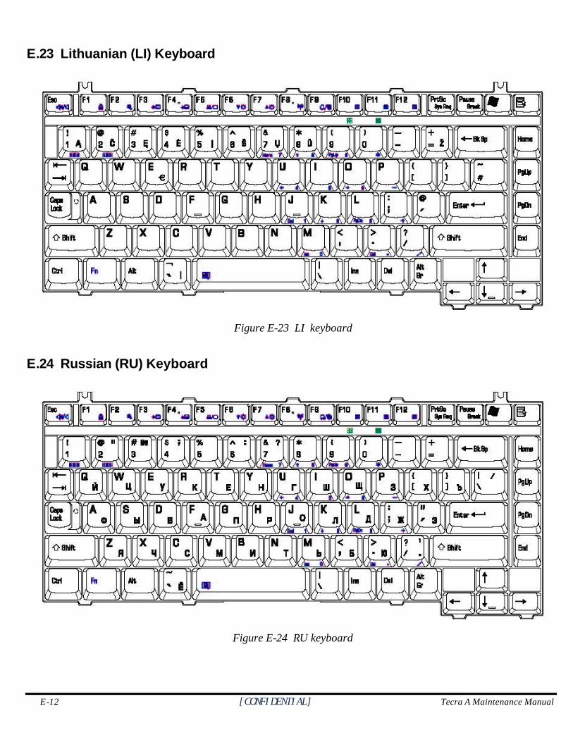
E-12 [CONFIDENTIAL] Tecra A Maintenance Manual
E.23 Lithuanian (LI) Keyboard
Figure E-23 LI keyboard
E.24 Russian (RU) Keyboard
Figure E-24 RU keyboard
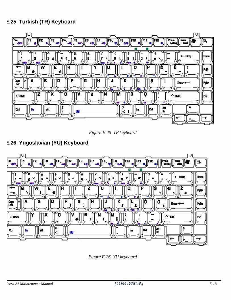
Tecra A6 Maintenance Manual [CONFIDENTIAL] E-13
E.25 Turkish (TR) Keyboard
Figure E-25 TR keyboard
E.26 Yugoslavian (YU) Keyboard
Figure E-26 YU keyboard
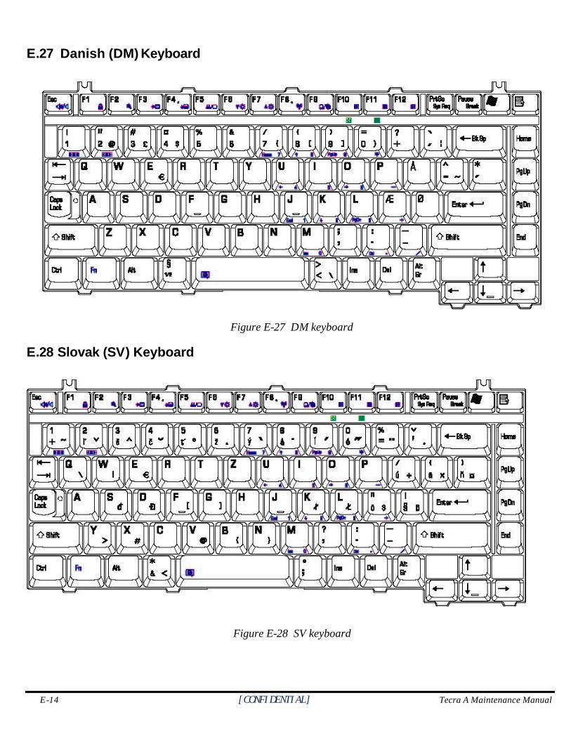
E-14 [CONFIDENTIAL] Tecra A Maintenance Manual
E.27 Danish (DM) Keyboard
Figure E-27 DM keyboard
E.28 Slovak (SV) Keyboard
Figure E-28 SV keyboard
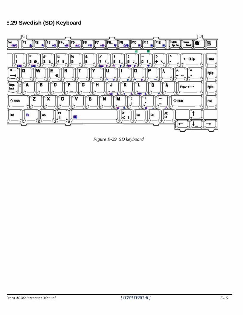
Tecra A6 Maintenance Manual [CONFIDENTIAL] E-15
E.29 Swedish (SD) Keyboard
Figure E-29 SD keyboard
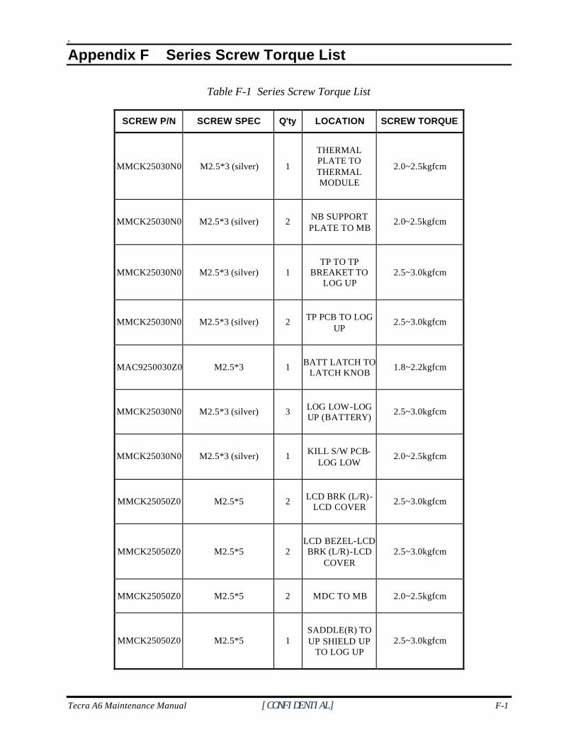
Tecra A6 Maintenance Manual [CONFIDENTIAL] F-1
F.
Appendix F Series Screw Torque List
Table F-1 Series Screw Torque List
SCREW P/N SCREW SPEC Q'ty LOCATION SCREW TORQUE
MMCK25030N0 M2.5*3 (silver) 1
THERMAL PLATE TO THERMAL MODULE
2.0~2.5kgfcm
MMCK25030N0 M2.5*3 (silver) 2 NB SUPPORT PLATE TO MB
2.0~2.5kgfcm
MMCK25030N0 M2.5*3 (silver) 1 TP TO TP
BREAKET TO LOG UP
2.5~3.0kgfcm
MMCK25030N0 M2.5*3 (silver) 2 TP PCB TO LOG UP
2.5~3.0kgfcm
MAC9250030Z0 M2.5*3 1 BATT LATCH TO LATCH KNOB
1.8~2.2kgfcm
MMCK25030N0 M2.5*3 (silver) 3 LOG LOW-LOG UP (BATTERY)
2.5~3.0kgfcm
MMCK25030N0 M2.5*3 (silver) 1 KILL S/W PCB-LOG LOW
2.0~2.5kgfcm
MMCK25050Z0 M2.5*5 2 LCD BRK (L/R)-LCD COVER
2.5~3.0kgfcm
MMCK25050Z0 M2.5*5 2 LCD BEZEL-LCD BRK (L/R)-LCD
COVER 2.5~3.0kgfcm
MMCK25050Z0 M2.5*5 2 MDC TO MB 2.0~2.5kgfcm
MMCK25050Z0 M2.5*5 1 SADDLE(R) TO UP SHIELD UP
TO LOG UP 2.5~3.0kgfcm
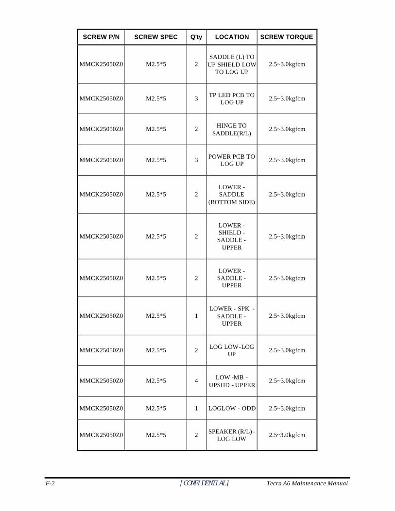
F-2 [CONFIDENTIAL] Tecra A6 Maintenance Manual
SCREW P/N SCREW SPEC Q'ty LOCATION SCREW TORQUE
MMCK25050Z0 M2.5*5 2 SADDLE (L) TO
UP SHIELD LOW TO LOG UP
2.5~3.0kgfcm
MMCK25050Z0 M2.5*5 3 TP LED PCB TO LOG UP
2.5~3.0kgfcm
MMCK25050Z0 M2.5*5 2 HINGE TO SADDLE(R/L)
2.5~3.0kgfcm
MMCK25050Z0 M2.5*5 3 POWER PCB TO LOG UP
2.5~3.0kgfcm
MMCK25050Z0 M2.5*5 2 LOWER - SADDLE
(BOTTOM SIDE) 2.5~3.0kgfcm
MMCK25050Z0 M2.5*5 2
LOWER - SHIELD - SADDLE -
UPPER
2.5~3.0kgfcm
MMCK25050Z0 M2.5*5 2 LOWER - SADDLE -
UPPER 2.5~3.0kgfcm
MMCK25050Z0 M2.5*5 1 LOWER - SPK -
SADDLE - UPPER
2.5~3.0kgfcm
MMCK25050Z0 M2.5*5 2 LOG LOW-LOG UP
2.5~3.0kgfcm
MMCK25050Z0 M2.5*5 4 LOW -MB - UPSHD - UPPER
2.5~3.0kgfcm
MMCK25050Z0 M2.5*5 1 LOGLOW - ODD 2.5~3.0kgfcm
MMCK25050Z0 M2.5*5 2 SPEAKER (R/L) -LOG LOW
2.5~3.0kgfcm
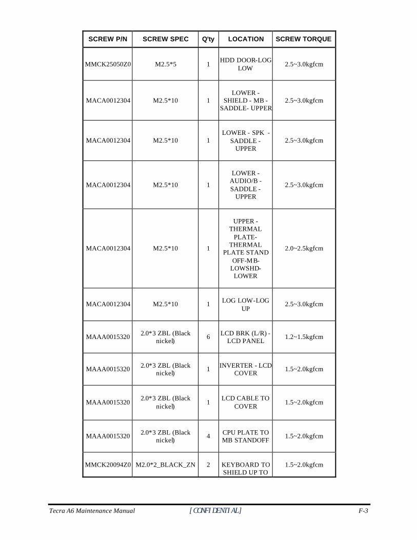
Tecra A6 Maintenance Manual [CONFIDENTIAL] F-3
SCREW P/N SCREW SPEC Q'ty LOCATION SCREW TORQUE
MMCK25050Z0 M2.5*5 1 HDD DOOR-LOG
LOW 2.5~3.0kgfcm
MACA0012304 M2.5*10 1 LOWER -
SHIELD - MB - SADDLE- UPPER
2.5~3.0kgfcm
MACA0012304 M2.5*10 1 LOWER - SPK -
SADDLE - UPPER
2.5~3.0kgfcm
MACA0012304 M2.5*10 1
LOWER - AUDIO/B - SADDLE -
UPPER
2.5~3.0kgfcm
MACA0012304 M2.5*10 1
UPPER -THERMAL
PLATE-THERMAL
PLATE STAND OFF-MB-
LOWSHD-LOWER
2.0~2.5kgfcm
MACA0012304 M2.5*10 1 LOG LOW-LOG UP
2.5~3.0kgfcm
MAAA0015320 2.0*3 ZBL (Black nickel)
6 LCD BRK (L/R) - LCD PANEL
1.2~1.5kgfcm
MAAA0015320 2.0*3 ZBL (Black nickel)
1 INVERTER - LCD COVER
1.5~2.0kgfcm
MAAA0015320 2.0*3 ZBL (Black
nickel) 1
LCD CABLE TO COVER
1.5~2.0kgfcm
MAAA0015320 2.0*3 ZBL (Black nickel)
4 CPU PLATE TO MB STANDOFF
1.5~2.0kgfcm
MMCK20094Z0 M2.0*2_BLACK_ZN 2 KEYBOARD TO SHIELD UP TO
1.5~2.0kgfcm
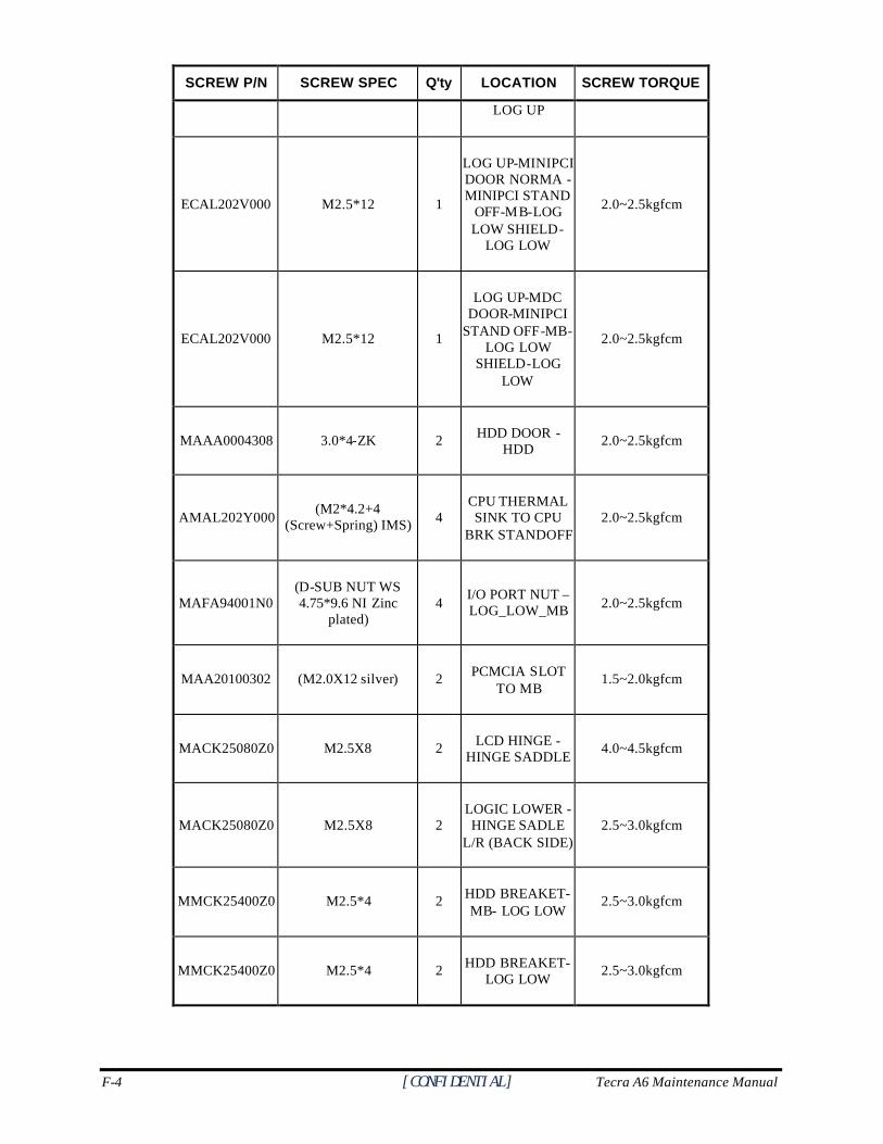
F-4 [CONFIDENTIAL] Tecra A6 Maintenance Manual
SCREW P/N SCREW SPEC Q'ty LOCATION SCREW TORQUE
LOG UP
ECAL202V000 M2.5*12 1
LOG UP-MINIPCI DOOR NORMA -MINIPCI STAND
OFF-MB-LOG LOW SHIELD-
LOG LOW
2.0~2.5kgfcm
ECAL202V000 M2.5*12 1
LOG UP-MDC DOOR-MINIPCI
STAND OFF-MB-LOG LOW
SHIELD-LOG LOW
2.0~2.5kgfcm
MAAA0004308 3.0*4-ZK 2 HDD DOOR - HDD
2.0~2.5kgfcm
AMAL202Y000 (M2*4.2+4
(Screw+Spring) IMS) 4 CPU THERMAL SINK TO CPU
BRK STANDOFF 2.0~2.5kgfcm
MAFA94001N0 (D-SUB NUT WS 4.75*9.6 NI Zinc
plated) 4
I/O PORT NUT – LOG_LOW_MB 2.0~2.5kgfcm
MAA20100302 (M2.0X12 silver) 2 PCMCIA SLOT TO MB
1.5~2.0kgfcm
MACK25080Z0 M2.5X8 2 LCD HINGE - HINGE SADDLE
4.0~4.5kgfcm
MACK25080Z0 M2.5X8 2 LOGIC LOWER - HINGE SADLE
L/R (BACK SIDE) 2.5~3.0kgfcm
MMCK25400Z0 M2.5*4 2 HDD BREAKET- MB- LOG LOW
2.5~3.0kgfcm
MMCK25400Z0 M2.5*4 2 HDD BREAKET- LOG LOW
2.5~3.0kgfcm
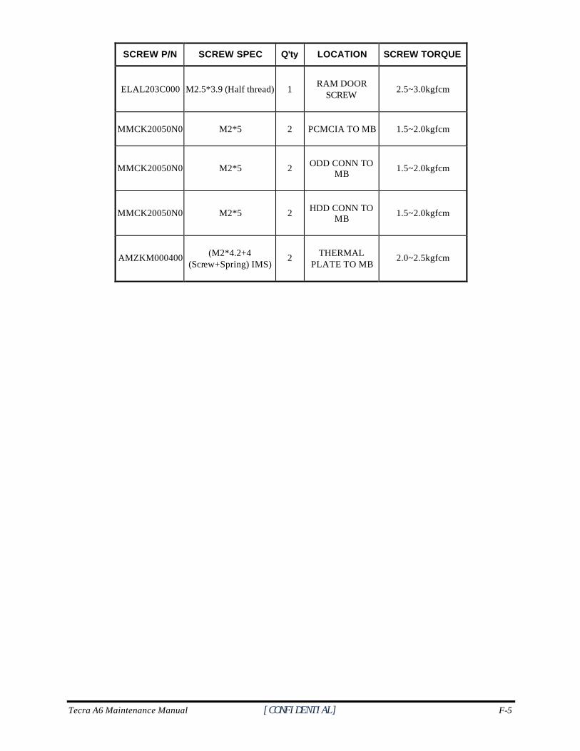
Tecra A6 Maintenance Manual [CONFIDENTIAL] F-5
SCREW P/N SCREW SPEC Q'ty LOCATION SCREW TORQUE
ELAL203C000 M2.5*3.9 (Half thread) 1 RAM DOOR
SCREW 2.5~3.0kgfcm
MMCK20050N0 M2*5 2 PCMCIA TO MB 1.5~2.0kgfcm
MMCK20050N0 M2*5 2 ODD CONN TO MB
1.5~2.0kgfcm
MMCK20050N0 M2*5 2 HDD CONN TO MB
1.5~2.0kgfcm
AMZKM000400 (M2*4.2+4 (Screw+Spring) IMS)
2 THERMAL PLATE TO MB
2.0~2.5kgfcm

F-6 [CONFIDENTIAL] Tecra A6 Maintenance Manual
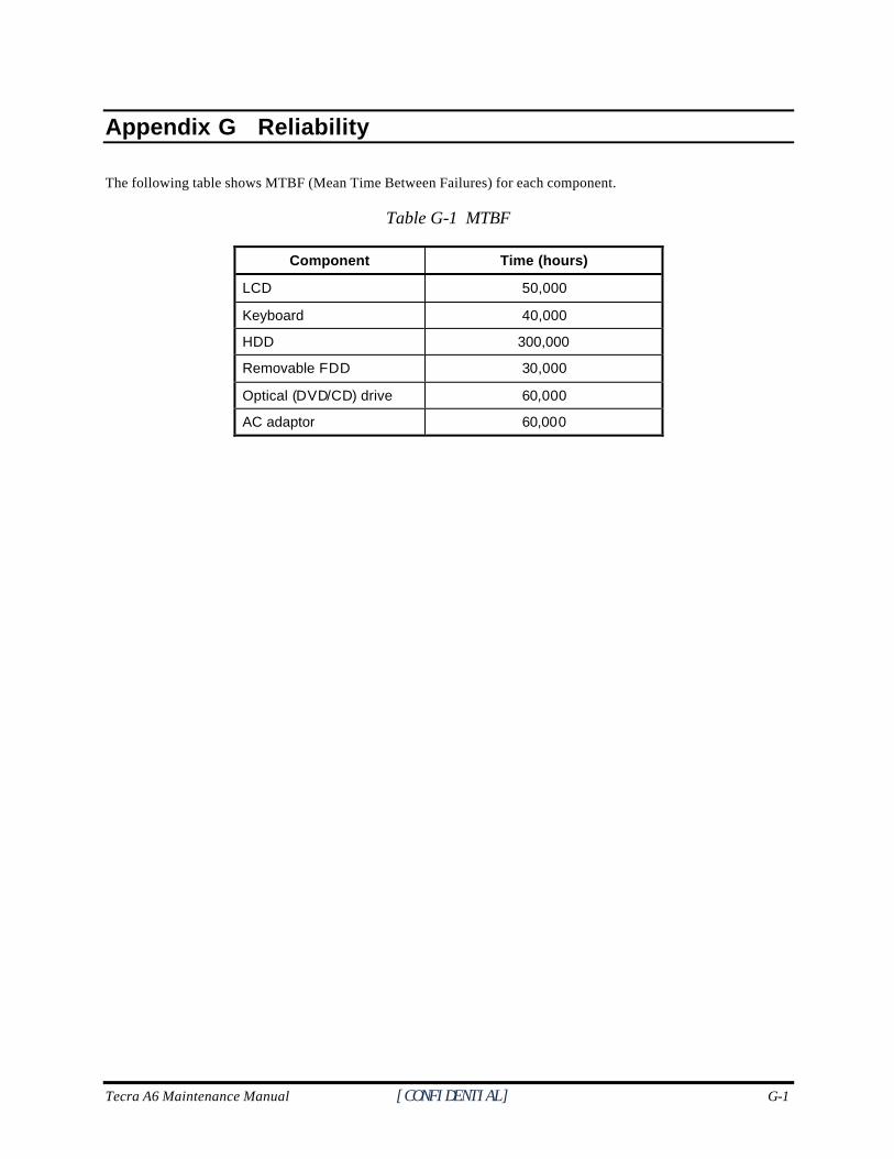
Tecra A6 Maintenance Manual [CONFIDENTIAL] G-1
Appendix G
Appendix G Reliability
The following table shows MTBF (Mean Time Between Failures) for each component.
Table G-1 MTBF
Component Time (hours)
LCD 50,000
Keyboard 40,000
HDD 300,000
Removable FDD 30,000
Optical (DVD/CD) drive 60,000
AC adaptor 60,000