Embed Size (px)
Citation preview
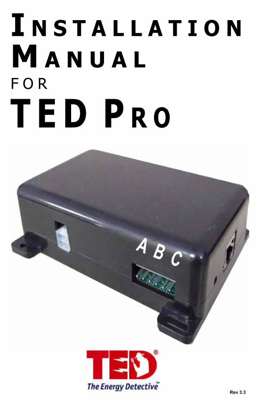
I n s t a l l a t I o nM a n u a l f o r
t E D P r o
A B C
Rev 3.3

© Copyright 2013 Energy, Inc. All rights reserved www.theenergydetective.com
Page 2
* * * * * * * * * * * * * * * * * * * * * * * * * * * * * * * * * * * * * * * *
* * * * * * * * * * * * * * * * * * * * * * * * * * * * * * * * * * * * * * * * *
* * * * * * * * * * * * * * * * * * * * * * * * * * * * * * * * * * * * * * * * *
* * * * * * * * * * * * * * * * * * * * * * * * * * * * * * * * * * * * * * * * *
IMPORTANT:The installation of your TED Pro system is a several-step process. The 1st step is the installation of the MTU Pro. After the MTU Pro is installed, Step 2 is the installation of the ECC, and access to the Footprints Software.
If the equipment is used in a manner not specified by the manufacturer, the protection provided by the equipment may be impaired.
© Copyright 2013 Energy, Inc. All rights reserved www.theenergydetective.com
* * * * * * * * * * * * * * * * * * * * * * * * * * * * * * * * * * * * * * * *
* * * * * * * * * * * * * * * * * * * * * * * * * * * * * * * * * * * * * * * * *
* * * * * * * * * * * * * * * * * * * * * * * * * * * * * * * * * * * * * * * * *Page 3
* * * * * * * * * * * * * * * * * * * * * * * * * * * * * * * * * * * * * * * * *Rev 3.3
TA B L E O F C O N T E N T S
Introduction . . . . . . . . . . . . . . . . . . . . . . . . . . . . . . Page 4Operating Conditions . . . . . . . . . . . . . . . . . . . . . . . Page 4Three phase services . . . . . . . . . . . . . . . . . . . . . . . Page 5Single-phase from 3-phase . . . . . . . . . . .. . . . . . . . Page 5Components . . . . . . . . . . . . . . . . . . . . . . . . . . . . . . Page 6
Safety . . . . . . . . . . . . . . . . . . . . . . . . . . . . . . . . . . Page 7
Installation . . . . . . . . . . . . . . . . . . . . . . . . . . . . . . Page 8
Communication Options . . . . . . . . . . . . . . . . . . Page 11Power Cable Connections . . . . . . . . . . . . . . . . Page 12Current Transformers . . . . . . . . . . . . . . . . . . . . . Page 13 Testing the System . . . . . . . . . . . . . . . . . . . . . . Page 16Configuration Options . . . . . . . . . . . . . . . . . . . . Page 17
Appendix A Wiring Diagrams . . . . . . . . . . . . . . Page 20Appendix B Rogowski Coils . . . . . . . . . . . . . . . Page 24Appendix C Firmware Update . . . . . . . . . . . . . . Page 26
PART I
PART II
PART III
PART IV
Appendix
© Copyright 2013 Energy, Inc. All rights reserved www.theenergydetective.com
Page 4
* * * * * * * * * * * * * * * * * * * * * * * * * * * * * * * * * * * * * * * *
* * * * * * * * * * * * * * * * * * * * * * * * * * * * * * * * * * * * * * * * *
* * * * * * * * * * * * * * * * * * * * * * * * * * * * * * * * * * * * * * * * *
* * * * * * * * * * * * * * * * * * * * * * * * * * * * * * * * * * * * * * * * *
UseCondition
TemperatureRelative Humidity
AltitudeVoltage
Maximum Power
IndoorDry
10° - 40°C< 80%
3,300M95-277VAC
5W
Indoor/Outdoor Dry /Damp
- 40°C to +50C< 95%3,300M
200-600 VAC4.5W
Display & ECC MTU & CTs
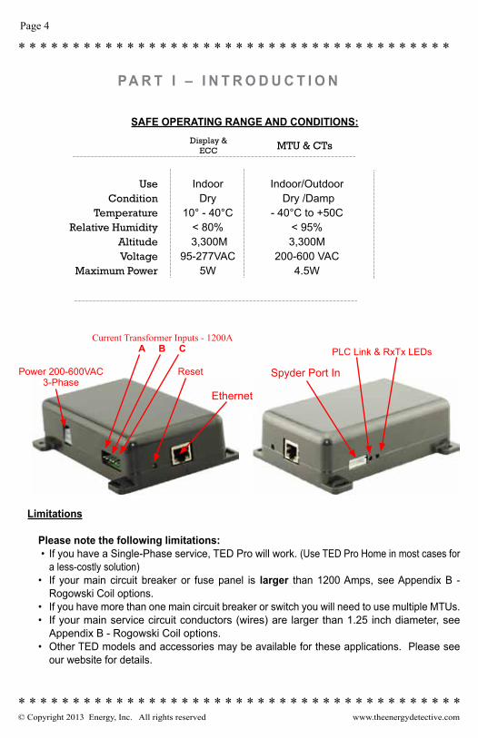
SAFE OPERATING RANGE AND CONDITIONS:
Limitations
Please note the following limitations: • If you have a Single-Phase service, TED Pro will work. (Use TED Pro Home in most cases for
a less-costly solution)• If your main circuit breaker or fuse panel is larger than 1200 Amps, see Appendix B -
Rogowski Coil options.• If you have more than one main circuit breaker or switch you will need to use multiple MTUs.• If your main service circuit conductors (wires) are larger than 1.25 inch diameter, see
Appendix B - Rogowski Coil options.• Other TED models and accessories may be available for these applications. Please see
our website for details.
PA R T I – I N T R O D U C T I O N
Current Transformer Inputs - 1200AA B C PLC Link & RxTx LEDs
Spyder Port In
Ethernet
ResetPower 200-600VAC3-Phase

© Copyright 2013 Energy, Inc. All rights reserved www.theenergydetective.com
* * * * * * * * * * * * * * * * * * * * * * * * * * * * * * * * * * * * * * * *
* * * * * * * * * * * * * * * * * * * * * * * * * * * * * * * * * * * * * * * * *
* * * * * * * * * * * * * * * * * * * * * * * * * * * * * * * * * * * * * * * * *Page 5
* * * * * * * * * * * * * * * * * * * * * * * * * * * * * * * * * * * * * * * * *Rev 3.3
TED MTU 3-PHASE OPERATION
3-Phase Services• TED is designed to work on most 3-phase 50-60HZ electrical services worldwide. TED will work
on 3PH-4W Wye, 3-PH-3W Delta 1 or 3PH-4W Hi-Leg Delta services anywhere where the line-line nominal voltage is between 200VAC and 600VAC. For specific connection drawings for each type of service see Appendix.
• Common 3-Phase Electrical Services around the world include:o 200V 3PH-3W Delta (Japan)o 208Y/120V 3PH-4W Wye (North America)o 240V 3PH-3W Delta (North America)1
o 240/120 3PH-4W Hi-Leg Delta (North America)o 380Y/220V 3PH-4W Wye or 380V 3PH-3W Delta (Asia)1 o 400Y/230V3PH-4W Wye or 380V 3PH-3W Delta (Europe)1
o 415Y/240V 3PH-4W Wye or 380V 3PH-3W Delta (UK, Australia/NZ, India)1
o 480Y/277V 3PH-4W Wye or 480V 3-PH-3W Delta (North America)1
o 600/347V 3PH-4W Wye or 600V 3PH-3W Delta (Canada) 1,2
• Service voltages shown above are common systems. There are other configurations. If yours is not listed and you are not sure, please contact Energy, Inc. Tech Support for assistance.
• TED is suitable for services of up to 5000 Amps. For services over 1200 Amps, see Appendix B, Rogowski Coil options
• Standard CTs and models are suitable for services with up to 3 parallel cables per phase that each have a maximum outside diameter up to 23mm (or 500 MCM). Optional CTs are available for conductors up to 30mm (or 750 MCM). For larger conductors, bus bars, or more than 3 parallel conductors per phase, see Appendix B, Rogowski Coil Options.
1 Delta Services and Wye services where voltage between line-and-neutral exceeds 277V cannot
use PLC communication between the MTU and ECC. In these cases the MTU must be mounted outside the electrical panel and Ethernet communication method must be used. The MTU and ECC will need to be connected to the Local Area Network (or connected to each other via Ethernet.) *277V ECC power cord kit is available. http://www.theenergydetective.com/tedprostore.html
2 800A and 1200A models include a CT harness and additional sets of CTs for each additional paral-lel conductor.
3 Standard TED Pro MTU is provided with 400A current transformers. For small services 200A or less, where space is limited, it is highly recommended that customer use 200A current transformers (Model CT601B). Please specify with order.
Single-Phase ServicesTED Pro is designed to work on 3-Phase services, however it is possible to configure it for single-phase services. TED Pro Home is recommended for single-phase services and provides a much smaller, more accurate and less costly solution for single-phase services up to 400A. TED Pro MTU

© Copyright 2013 Energy, Inc. All rights reserved www.theenergydetective.com
Page 6
* * * * * * * * * * * * * * * * * * * * * * * * * * * * * * * * * * * * * * * *
* * * * * * * * * * * * * * * * * * * * * * * * * * * * * * * * * * * * * * * * *
* * * * * * * * * * * * * * * * * * * * * * * * * * * * * * * * * * * * * * * * *
* * * * * * * * * * * * * * * * * * * * * * * * * * * * * * * * * * * * * * * * *
TED Pro Energy Monitoring System includes:• One (1) MTU3000 Measuring Transmitting Unit (MTU Pro)• One (1) ECC (with Footprints firmware embedded)• One (1) wired or wireless Display (if purchase included Display)• Associated cables, power supplies, installation brochure • TED Pro 400A: Three (3) 400A Current Transformers (CTs)• TED Pro 800A: Six (6) 400A Current Transformers and Three (3) CT Harnesses • TED Pro 1200A: Nine (9) 400A Current Transformers and Three (3) CT Harnesses
SYSTEM COMPONENTS
Common 1-Phase Electrical Services around the world include:• 208Y/120V 1PH-3W Single Phase service derived from 3-Phase system (North America)• 240/120V 1PH-3W (North America)• 230V 1PH-2W (Europe and most other countries in the world)• TED Pro MTU Pro will not work on 120V 1PH-2W services
UnpackingUnpack TED and ensure that all parts are included in the package.
A) One (1) Measuring Transmitting Unit (MTU Pro)
D) Three (3) Model QX400CT Current Transformers (CT’s)
B) One (1) ECC (Energy Control Center).
C) Power Cables for MTU Pro and, ECC; Ethernet Cable, (Low-voltage power adapter if optional wireless Display included)
F) Installation Manual - Please Read Carefully
E) Three (3) CT Black-loop Adapter Harnesses (800A and 1200A systems only)
Pro can be configured to work on any single phase service where the line-line nominal voltage or line-to-neutral nominal voltage is between 200VAC and 277VAC. For specific connection drawings for each type of service see the Appendix.

© Copyright 2013 Energy, Inc. All rights reserved www.theenergydetective.com
* * * * * * * * * * * * * * * * * * * * * * * * * * * * * * * * * * * * * * * *
* * * * * * * * * * * * * * * * * * * * * * * * * * * * * * * * * * * * * * * * *
* * * * * * * * * * * * * * * * * * * * * * * * * * * * * * * * * * * * * * * * *Page 7
* * * * * * * * * * * * * * * * * * * * * * * * * * * * * * * * * * * * * * * * *Rev 3.3
PA R T I I – S A F E T Y
THE MTU AND CTs OF THE TED PrO sYsTEM MUsT BE INsTALLED BY A LICENsED ELECTrICIAN
This manual provides the steps necessary to safely install the MTU and Current Transformers (CTs). For detailed installation and operation of other components and software, please find it on the TED website: www.theenergydetective.com
Every effort has been made in providing for the safe, secure installation of TED. The installation of TED requires the cover of the main electrical circuit breaker panel to be removed. After the circuit breaker panel cover has been removed, the potential hazard of shock, burn, or even electrocution now exists. Do not attempt to complete this installation unless you are a licensed electrician familiar with the electrical components and operation of the circuit breaker panel. Even when the main circuit breaker has been turned to the “OFF” position, certain areas within the circuit breaker panel may still be electrified. Do not attempt installation unless you know where these electrified areas are.
This symbol will be found throughout the instructions where there is a po-tential for electric shock, burn, or even electrocution. Do not attempt to com-plete the noted section if you are not an electrician, or qualified installer.
WARNING - These servicing instructions are for use by qualified personnel only. To reduce the risk of electric shock, DO NOT perform any servicing other than that contained in these operational instruc-tions unless you are qualified to do so.
WARNING - The MTU must be connected to a switch or circuit breaker in close proximity to the equip-ment and within easy reach of the operator. It must be marked as the disconnecting device for the MTU.
WARNING - If the equipment is used in a manner not specified in these instructions, the protection provided by the equipment may be impaired.
TESTED TO COMPLY WITH FCC STANDARDS
FOR HOME AND OFFICE USE
EnErgy, Inc. ModEl TEd3000 / TEd Pro This device complies with part 15 of the FCC Rules.
Operation is subject to the following two conditions:
(1) This device may not cause harmful interference,
and (2) This device must accept any interference received,
including interference that may cause undesired operations.
FCC Part 15 SubPart BEU/EN 61326-1

© Copyright 2013 Energy, Inc. All rights reserved www.theenergydetective.com
Page 8
* * * * * * * * * * * * * * * * * * * * * * * * * * * * * * * * * * * * * * * *
* * * * * * * * * * * * * * * * * * * * * * * * * * * * * * * * * * * * * * * * *
* * * * * * * * * * * * * * * * * * * * * * * * * * * * * * * * * * * * * * * * *
* * * * * * * * * * * * * * * * * * * * * * * * * * * * * * * * * * * * * * * * *
B E F O R E Y O U S TA R T• Do not begin installation until you have read the “Safety” section of this manual.• Read all instructions before beginning installation.
Estimated Installation Time:Professional Installer: 30 minutes
Equipment Needed:- Flathead screwdriver - small and large- Phillips screwdriver - small and large- Flashlight
QUALIFIED ELECTRICIANS OR PROFESSIONAL INSTALLERS FAMILIAR WITH ALL ASPECTS OF ELECTRICAL WIRING AND THEORY MAY USE THE FOLLOWING INSTRUCTIONS FOR INSTALLATION OF TED Pro MTU.
TED will work on single-phase services, however TED Pro Residential will prove to be a smaller and more cost effective solution. For services where there are two-or-more main circuit breaker panels you will need one additional MTU for each main circuit breaker or panel.
For services with Wind/Solar or Standby Generator, an additional MTU will be required to measure GENERATION and NET.
All wiring in the United States must be installed in accordance with the latest adopted edition of the Na-tional Electrical Code (ANSI/NFPA 70, NEC) and state or local requirements. All wiring in Canada must be installed in accordance with the latest adopted edition of the Canadian Electrical Code (CSA C22.2 CEC, Part I) and any provincial or local requirements.
Wiring in other countries and jurisdictions should be done in accordance with the rules and regulations in effect for the installing location. Contact your local power authority or local regulator for more information.
PA R T I I I – I N S TA L L AT I O N
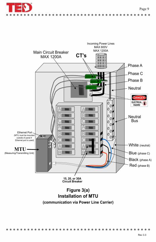
Neutral
Phase C
Phase A
Incoming Power LinesMAX 600VMAX 1200A
White (neutral)
Black (phase A)
NeutralBus
15, 20, or 30ACircuit Breaker
CT’sMain Circuit BreakerMAX 1200A
ABCABCAB
ABCABCAB
Red (phase B)
Phase B
Blue (phase C)MTU
(Measuring/Transmitting Unit)
Ethernet Port(MTU must be mounted
outside of panel ifEthernet port is used)
C
B
A
© Copyright 2013 Energy, Inc. All rights reserved www.theenergydetective.com
* * * * * * * * * * * * * * * * * * * * * * * * * * * * * * * * * * * * * * * *
* * * * * * * * * * * * * * * * * * * * * * * * * * * * * * * * * * * * * * * * *
* * * * * * * * * * * * * * * * * * * * * * * * * * * * * * * * * * * * * * * * *Page 9
* * * * * * * * * * * * * * * * * * * * * * * * * * * * * * * * * * * * * * * * *Rev 3.3
Figure 3(a)Installation of MTU
(communication via Power Line Carrier)
Neutral
Phase C
Phase A
Incoming Power LinesMAX 600VMAX 1200A
White (neutral)
Black (phase A)
NeutralBus
15, 20, or 30ACircuit Breaker
CT’sMain Circuit BreakerMAX 1200A
ABCABCAB
ABCABCAB
Red (phase B)
Phase B
Blue (phase C)MTU
(Measuring/Transmitting Unit)
Ethernet Port(MTU must be mounted
outside of panel ifEthernet port is used)
C
B
A
© Copyright 2013 Energy, Inc. All rights reserved www.theenergydetective.com
Page 10
* * * * * * * * * * * * * * * * * * * * * * * * * * * * * * * * * * * * * * * *
* * * * * * * * * * * * * * * * * * * * * * * * * * * * * * * * * * * * * * * * *
* * * * * * * * * * * * * * * * * * * * * * * * * * * * * * * * * * * * * * * * *
* * * * * * * * * * * * * * * * * * * * * * * * * * * * * * * * * * * * * * * * *
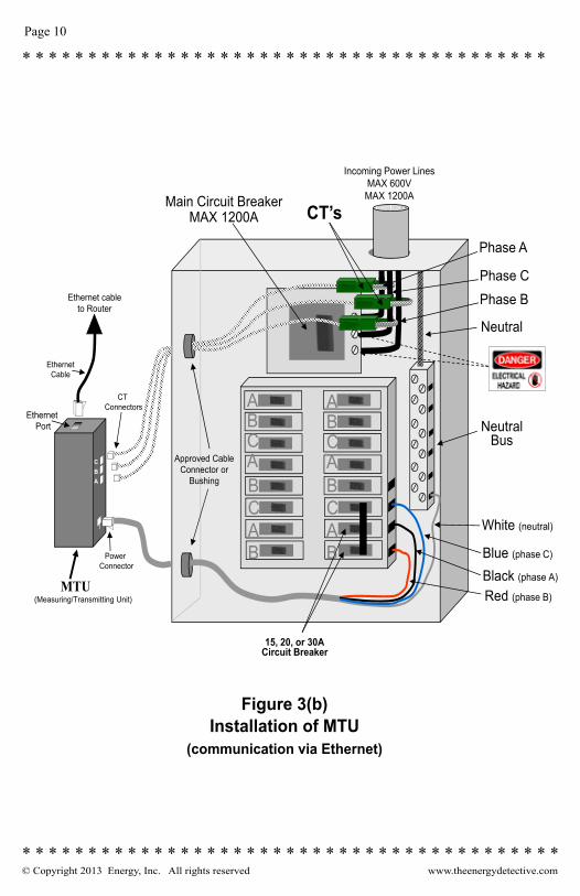
Figure 3(b)Installation of MTU
(communication via Ethernet)
Neutral
Phase C
Phase A
Incoming Power LinesMAX 600VMAX 1200A
White (neutral)
Black (phase A)
NeutralBus
15, 20, or 30ACircuit Breaker
CT’sMain Circuit BreakerMAX 1200A
ABCABCAB
ABCABCAB
Red (phase B)
Phase B
Blue (phase C)
MTU(Measuring/Transmitting Unit)
EthernetPort
Power Connector
CTConnectors
Approved Cable Connector or
Bushing
Ethernet cableto Router
EthernetCable
CBA
© Copyright 2013 Energy, Inc. All rights reserved www.theenergydetective.com
* * * * * * * * * * * * * * * * * * * * * * * * * * * * * * * * * * * * * * * *
* * * * * * * * * * * * * * * * * * * * * * * * * * * * * * * * * * * * * * * * *
* * * * * * * * * * * * * * * * * * * * * * * * * * * * * * * * * * * * * * * * *Page 11
* * * * * * * * * * * * * * * * * * * * * * * * * * * * * * * * * * * * * * * * *Rev 3.3
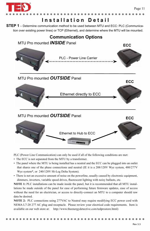
STEP 1 – Determine communication method to be used between MTU and ECC: PLC (Communica-tion over existing power lines) or TCP (Ethernet), and determine where the MTU will be mounted.
I n s t a l l a t i o n D e t a i l
Communication OptionsMTU Pro mounted INSIDE Panel ECC
PLC - Power Line Carrier
MTU Pro mounted OUTSIDE PanelECC
Ethernet directly to ECC
MTU Pro mounted OUTSIDE Panel ECC
Ethernet to Hub to ECC
PLC (Power Line Communication) can only be used if all of the following conditions are met:• The ECC is not separated from the MTU by a transformer.• The panel where the MTU is being installed has a neutral and the ECC can be plugged into an outlet
that shares one of the phase connections and neutral (IE it is a 208/120V Wye system, 480/277V Wye system*, or 240/120V Hi-Leg Delta System).
• There is not an excessive amount of noise on the powerline, usually caused by electronic equipment, dimmers, inverters, variable speed drives, fluorescent lighting with noisy ballasts, etc.
NOTE 1: PLC installations can be made inside the panel, but it is recommended that all MTU instal-lations be made outside of the panel for ease of performing future firmware updates, ease of access without the need for an electrician, or access to directly-connect an MTU to a computer should raw data be desired.NOTE 2: PLC connections using 277VAC to Neutral may require modifying ECC power cord with NEMA L7-20 277 AC plug and receptacle. Please review your electrical code requirements. Item is available on our web store at: http://www.theenergydetective.com/tedprostore.html)

© Copyright 2013 Energy, Inc. All rights reserved www.theenergydetective.com
Page 12
* * * * * * * * * * * * * * * * * * * * * * * * * * * * * * * * * * * * * * * *
* * * * * * * * * * * * * * * * * * * * * * * * * * * * * * * * * * * * * * * * *
* * * * * * * * * * * * * * * * * * * * * * * * * * * * * * * * * * * * * * * * *
* * * * * * * * * * * * * * * * * * * * * * * * * * * * * * * * * * * * * * * * *
A) Turn off power.B) Remove circuit breaker panel cover.C) Note the Serial Number of the MTU as shown on the label. It consists of six digits in the form “12 34 56.”
You will need to know this number to connect the MTU to the ECC Network.D) Connect the black, red and blue wires from the MTU power cord to a spare 15,20 or 30 Amp three-
pole circuit breaker in the panel. See Appendix for specific wiring diagrams for your system. i. If there is no spare circuit breaker, the black/red/blue wires can be attached to any 15, 20
or 30 Amp 3-pole circuit breaker in the panel, provided that the circuit breaker is approved for 2 conduc-tors and this is acceptable to the “authority having jurisdiction in the installation location” (it is generally acceptable); If a 3-pole circuit breaker is not available, then use an approved handle-tie to create one.
ii. If the circuit breakers in the panel being monitored are greater than 30 amps, an in-line 15 or 20A fuse should be added to each power cable connection, Pre-made cables with in-line fuses are available in our Accessory Store. http://www.theenergydetective.com/tedprostore.html (Please refer to NEC, CEC and your local electrical code.) An alternate method would be to run a 3-phase power circuit from a 15 or 20A circuit breaker in a nearby panel to a junction box or terminal block near the panel being monitored and make all MTU power connections there. The circuit must be from the same source as the load being measured by the MTU. IE it must be from the same service and at the same voltage without any transformers between.
E) If there is no spare circuit breaker, the black/red/blue wires can be attached to any 15, 20 or 30 Amp 3-pole circuit breaker in the panel, provided that the circuit breaker is approved for 2 conduc-tors and this is acceptable to the “authority having jurisdiction in the installation location” (it is generally acceptable); If a 3-pole circuit breaker is not available, then use an approved handle-tie to create one.
F) Do not connect the Power Cable to the MTU until you have the CTs connected.
NOTE 1: The black, red and blue wires will normally connect to the corresponding 3 phases on the cir-cuit breaker (IE Black wire to Phase A, Red wire to Phase B and Blue wire to phase C). The CT inputs on the MTU are left-to-right: Phase A, Phase B, Phase C (see image on front cover of this booklet) and must be matched to the corresponding wires for proper readings. 4 wire Delta is an exception, see Appendix A-3. Some Canadian Standards may have phases marked differently in the panel, this doesn’t matter as long as the MTU power cable wires and CT inputs correspond.
NOTE 2: For optimal PLC Communication, the ECC should be plugged into a circuit on the same phase as the black wire on the MTU power cable. If the ECC cannot be connected to phase A, the
TURN OFF ALL POWER TO THE CIRCUIT BREAKER PANEL BY TURNING OFF THE MAIN BREAKER OR MAIN SWITCH.
STEP 3 - INSTALLING THE POWER CABLE AND MEASURING TRANSMITTING UNIT (MTU).
NOTE 3: PLC signal is transmitted on the black wire of the MTU power cable, (normally connected to phase A). Communication is optimized when the ECC is plugged into an outlet on Phase A. If not practical to plug the ECC into a phase A outlet, the Phase A voltage and CT connections of the MTU may need to be swapped to match the phase powering the ECC.
Correct
© Copyright 2013 Energy, Inc. All rights reserved www.theenergydetective.com
* * * * * * * * * * * * * * * * * * * * * * * * * * * * * * * * * * * * * * * *
* * * * * * * * * * * * * * * * * * * * * * * * * * * * * * * * * * * * * * * * *
* * * * * * * * * * * * * * * * * * * * * * * * * * * * * * * * * * * * * * * * *Page 13
* * * * * * * * * * * * * * * * * * * * * * * * * * * * * * * * * * * * * * * * *Rev 3.3
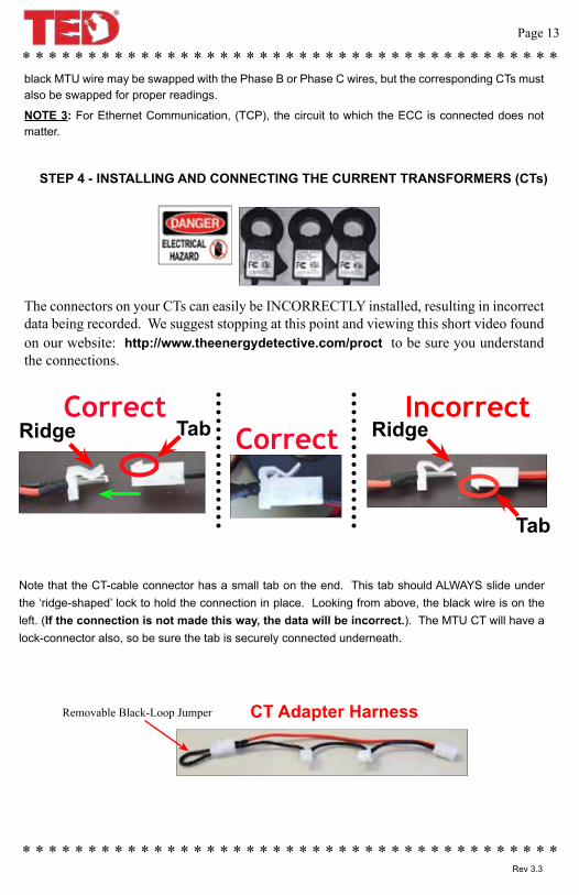
Correct Incorrect
Note that the CT-cable connector has a small tab on the end. This tab should ALWAYS slide under the ‘ridge-shaped’ lock to hold the connection in place. Looking from above, the black wire is on the left. (If the connection is not made this way, the data will be incorrect.). The MTU CT will have a lock-connector also, so be sure the tab is securely connected underneath.
Ridge Tab Ridge
Tab
Removable Black-Loop Jumper CT Adapter Harness
The connectors on your CTs can easily be INCORRECTLY installed, resulting in incorrect data being recorded. We suggest stopping at this point and viewing this short video found on our website: http://www.theenergydetective.com/proct to be sure you understand the connections.
Correct
STEP 4 - INSTALLING AND CONNECTING THE CURRENT TRANSFORMERS (CTs)
black MTU wire may be swapped with the Phase B or Phase C wires, but the corresponding CTs must also be swapped for proper readings.
NOTE 3: For Ethernet Communication, (TCP), the circuit to which the ECC is connected does not matter.
© Copyright 2013 Energy, Inc. All rights reserved www.theenergydetective.com
Page 14
* * * * * * * * * * * * * * * * * * * * * * * * * * * * * * * * * * * * * * * *
* * * * * * * * * * * * * * * * * * * * * * * * * * * * * * * * * * * * * * * * *
* * * * * * * * * * * * * * * * * * * * * * * * * * * * * * * * * * * * * * * * *
* * * * * * * * * * * * * * * * * * * * * * * * * * * * * * * * * * * * * * * * *
CAUTION – IF THIS IS A COMBINATION PANEL, THE LUGS ON THE PRIMARY SIDE OF THE MAIN BREAKER ARE PROBABLY STILL HOT.A) The CTs must be installed with the red polarity dots facing towards the source of power (the utility-
meter). If all three CTs are not installed in this manner, the readings will be wrong. Note: If you have solar, wind or generator, you will need an additional MTU if you want to measure: Gen-eration, Load and Net Utility. Please see solar/wind section of our website for details.
• Note: Do not install the CT over the neutral (N) (grounded) conductor.
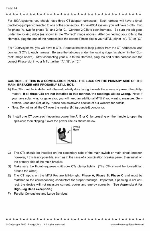
B) Install one CT over each incoming power line A, B or C, by pressing on the handle to open the split-core then clipping it over the power line as shown below.
C) The CTs should be installed on the secondary side of the main switch or main circuit breaker, however, if this is not possible, such as in the case of a combination breaker panel, then install on the primary side of the main breaker.
D) Make sure the thumb-squeeze split core CTs clamp tightly. (The CTs should be loose-fitting around the wires).
E) The CT inputs on the MTU Pro are left-to-right: Phase A, Phase B, Phase C and must be matched to the corresponding conductors for proper readings. Important, if phasing is not cor-rect, the device will not measure current, power and energy correctly. (See Appendix A for High-Leg Delta exception.)
F) Parallel Conductors and Large Services:
For 800A systems, you should have three CT-adapter harnesses. Each harness will have a small black-loop jumper connected to one of the connectors. For an 800A system, you will have 6-CTs. Two for phase ‘A’, two for phase ‘B’, and 2 for ‘C.’ Connect 2 CTs to each harness. Be sure the tab goes under the locking ridge (as shown in the “Correct” image above). After connecting your CTs to the Harness, plug the end of the harness into the correct Phase-slot in your MTU...either “A”, “B”, or “C.”
For 1200A systems, you will have 9-CTs. Remove the black loop-jumper from the CT-harnesses, and connect 3 CTs to each harness. Be sure the tab goes under the locking ridge (as shown in the “Cor-rect” image above). After connecting your CTs to the Harness, plug the end of the harness into the correct Phase-slot in your MTU...either “A”, “B”, or “C.”
PressHere
© Copyright 2013 Energy, Inc. All rights reserved www.theenergydetective.com
* * * * * * * * * * * * * * * * * * * * * * * * * * * * * * * * * * * * * * * *
* * * * * * * * * * * * * * * * * * * * * * * * * * * * * * * * * * * * * * * * *
* * * * * * * * * * * * * * * * * * * * * * * * * * * * * * * * * * * * * * * * *Page 15
* * * * * * * * * * * * * * * * * * * * * * * * * * * * * * * * * * * * * * * * *Rev 3.3
NOTE: All connectors are polarized and can only be inserted one way – do not force.NOTE: If installed on a 208Y/120V 1-PH 3-W system, only install two of the CTs and connect to the two
applicable ports on the MTU. The third CT is not used.NOTE: The TED Pro MTU is available in kits for 400A, 800A (for 2 parallel conductors), 1200A (for 3
parallel conductors), and Rogowski Coil kits for 2000A and 5000A Services.NOTE: Appendix B for Rogowski Coil instructions
G) Determine the best location to mount the MTU.i. Choose location where it will not interfere with existing equipment or wiring.ii. If installed in the panel, the MTU may be attached using double-sided tape (if allowed in your
jurisdiction), or with sheet metal or machine screws.iii. If installed outside the panel, it may be mounted directly to the wall using the mounting lugs on
the MTU, or it may be mounted in a suitably sized junction box.
H) Arrange and tie-wrap all wiring in a neat and tidy manner.I) Turn the power back on.
Do not close the electrical panel until you have completed the installation of the ECC and verified that correct data is being received from the MTU.
Close the Electrical Panel only after you have confirmed the correct operation.
Step 5 – ETHERNET WIRING• Neatly run a CAT-V cable from the MTU to the customer’s router or network location. Be sure to
use plenum-rated cables where required. Neatly route, protect and secure the cable.• Make the connections and plug into MTU and Router or Network Drop. Check that the LEDs on the
Ethernet jack indicate activity.
© Copyright 2013 Energy, Inc. All rights reserved www.theenergydetective.com
Page 16
* * * * * * * * * * * * * * * * * * * * * * * * * * * * * * * * * * * * * * * *
* * * * * * * * * * * * * * * * * * * * * * * * * * * * * * * * * * * * * * * * *
* * * * * * * * * * * * * * * * * * * * * * * * * * * * * * * * * * * * * * * * *
* * * * * * * * * * * * * * * * * * * * * * * * * * * * * * * * * * * * * * * * *
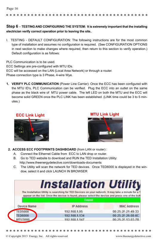
ECC Link Light MTU Link Light
Step 6 – TESTING AND CONFIGURING THE SYSTEM: It is extremely important that the installing electrician verify correct operation prior to leaving the site..
I. TESTING - DEFAULT CONFIGURATION: The following instructions are for the most common type of installation and assumes no configuration is required. (See CONFIGURATION OPTIONS in next section to make changes where required, then return to this section to verify operation.) Default configuration is as follows:
PLC Communication is to be used.ECC Settings are pre-configured with MTU IDs.ECC will be accessed on the LAN (Local Area Network) or through a router.Phase connection type is 3 Phase, 4-wire Wye.
1. VERIFY PLC COMMUNICATION (Power Line Carrier): Once the ECC has been configured with the MTU ID’s, PLC Communication can be verified. Plug the ECC into an outlet on the same phase as the black wire of MTU power cable. The left LED on both the MTU and the ECC will become solid GREEN once the PLC LINK has been established. (LINK time could be 3 to 5 min-utes.)
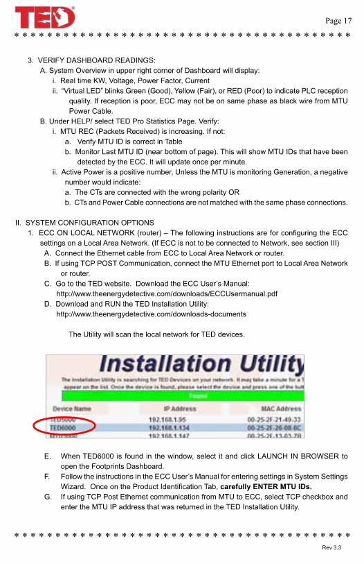
2. ACCESS ECC FOOTPRINTS DASHBOARD (from LAN or router) :A. Connect the Ethernet Cable from ECC to LAN drop or router.B. Go to TED website to download and RUN the TED Installation Utility: http://www.theenergydetective.com/downloads-documentsC. The Utility will scan the network for TED devices. Once TED6000 is displayed in the win-
dow, select it and click LAUNCH IN BROWSER
© Copyright 2013 Energy, Inc. All rights reserved www.theenergydetective.com
* * * * * * * * * * * * * * * * * * * * * * * * * * * * * * * * * * * * * * * *
* * * * * * * * * * * * * * * * * * * * * * * * * * * * * * * * * * * * * * * * *
* * * * * * * * * * * * * * * * * * * * * * * * * * * * * * * * * * * * * * * * *Page 17
* * * * * * * * * * * * * * * * * * * * * * * * * * * * * * * * * * * * * * * * *Rev 3.3
3. VERIFY DASHBOARD READINGS: A. System Overview in upper right corner of Dashboard will display:
i. Real time KW, Voltage, Power Factor, Current ii. “Virtual LED” blinks Green (Good), Yellow (Fair), or RED (Poor) to indicate PLC reception
quality. If reception is poor, ECC may not be on same phase as black wire from MTU Power Cable.
B. Under HELP/ select TED Pro Statistics Page. Verify: i. MTU REC (Packets Received) is increasing. If not:
a. Verify MTU ID is correct in Table b. Monitor Last MTU ID (near bottom of page). This will show MTU IDs that have been
detected by the ECC. It will update once per minute. ii. Active Power is a positive number, Unless the MTU is monitoring Generation, a negative
number would indicate: a. The CTs are connected with the wrong polarity OR b. CTs and Power Cable connections are not matched with the same phase connections.
II. SYSTEM CONFIGURATION OPTIONS1. ECC ON LOCAL NETWORK (router) – The following instructions are for configuring the ECC
settings on a Local Area Network. (If ECC is not to be connected to Network, see section III) A. Connect the Ethernet cable from ECC to Local Area Network or router.B. If using TCP POST Communication, connect the MTU Ethernet port to Local Area Network
or router.C. Go to the TED website. Download the ECC User’s Manual: http://www.theenergydetective.com/downloads/ECCUsermanual.pdfD. Download and RUN the TED Installation Utility: http://www.theenergydetective.com/downloads-documents
The Utility will scan the local network for TED devices.
E. When TED6000 is found in the window, select it and click LAUNCH IN BROWSER to open the Footprints Dashboard.
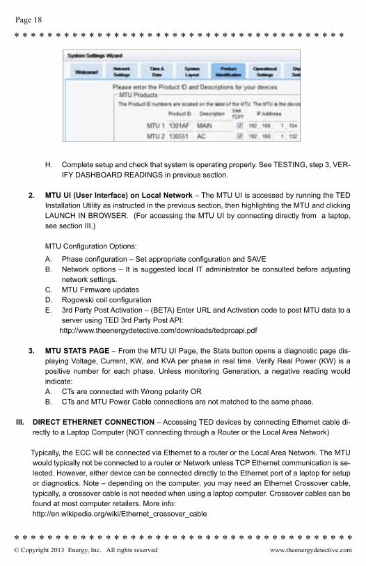
F. Follow the instructions in the ECC User’s Manual for entering settings in System Settings Wizard. Once on the Product Identification Tab, carefully ENTER MTU IDs.
G. If using TCP Post Ethernet communication from MTU to ECC, select TCP checkbox and enter the MTU IP address that was returned in the TED Installation Utility.
© Copyright 2013 Energy, Inc. All rights reserved www.theenergydetective.com
Page 18
* * * * * * * * * * * * * * * * * * * * * * * * * * * * * * * * * * * * * * * *
* * * * * * * * * * * * * * * * * * * * * * * * * * * * * * * * * * * * * * * * *
* * * * * * * * * * * * * * * * * * * * * * * * * * * * * * * * * * * * * * * * *
* * * * * * * * * * * * * * * * * * * * * * * * * * * * * * * * * * * * * * * * *
H. Complete setup and check that system is operating properly. See TESTING, step 3, VER-IFY DASHBOARD READINGS in previous section.
2. MTU UI (User Interface) on Local Network – The MTU UI is accessed by running the TED Installation Utility as instructed in the previous section, then highlighting the MTU and clicking LAUNCH IN BROWSER. (For accessing the MTU UI by connecting directly from a laptop, see section III.)
MTU Configuration Options:
A. Phase configuration – Set appropriate configuration and SAVEB. Network options – It is suggested local IT administrator be consulted before adjusting
network settings. C. MTU Firmware updatesD. Rogowski coil configurationE. 3rd Party Post Activation – (BETA) Enter URL and Activation code to post MTU data to a
server using TED 3rd Party Post API: http://www.theenergydetective.com/downloads/tedproapi.pdf
3. MTU STATS PAGE – From the MTU UI Page, the Stats button opens a diagnostic page dis-playing Voltage, Current, KW, and KVA per phase in real time. Verify Real Power (KW) is a positive number for each phase. Unless monitoring Generation, a negative reading would indicate:A. CTs are connected with Wrong polarity ORB. CTs and MTU Power Cable connections are not matched to the same phase.
III. DIRECT ETHERNET CONNECTION – Accessing TED devices by connecting Ethernet cable di-rectly to a Laptop Computer (NOT connecting through a Router or the Local Area Network)
Typically, the ECC will be connected via Ethernet to a router or the Local Area Network. The MTU would typically not be connected to a router or Network unless TCP Ethernet communication is se-lected. However, either device can be connected directly to the Ethernet port of a laptop for setup or diagnostics. Note – depending on the computer, you may need an Ethernet Crossover cable, typically, a crossover cable is not needed when using a laptop computer. Crossover cables can be found at most computer retailers. More info:
http://en.wikipedia.org/wiki/Ethernet_crossover_cable
© Copyright 2013 Energy, Inc. All rights reserved www.theenergydetective.com
* * * * * * * * * * * * * * * * * * * * * * * * * * * * * * * * * * * * * * * *
* * * * * * * * * * * * * * * * * * * * * * * * * * * * * * * * * * * * * * * * *
* * * * * * * * * * * * * * * * * * * * * * * * * * * * * * * * * * * * * * * * *Page 19
* * * * * * * * * * * * * * * * * * * * * * * * * * * * * * * * * * * * * * * * *Rev 3.3
1. COMPUTER SETTINGS: The computer’s Local Area Network settings must be set as follows for Ethernet Communication directly to the computer (No Router):IP: 192.168.7.1Subnet Mask: 255.255.255.0Gateway IP: 192.168.7.1The ECC User’s manual Appendix A gives an example of where to find these settings: http://www.theenergydetective.com/downloads/ECCUsermanual.pdf
2. MTU UI PAGE:
A. NOTE: Computer Network Settings must be set as shown above. B. Connect Ethernet Cable directly from MTU to Laptop to OR Connect MTU and Laptop via
Ethernet cable to a switch that is NOT connected to the Local Network or Router. C. Open a Web Browser, (Internet Explorer, Chrome, Safari, etc.) D. Type 192.168.7.3 into the address bar and press ENTER
3. FOOTPRINTS DASHBOARD (ECC Connection):
A. NOTE: Computer Network Settings must be set as listed above B. Connect Ethernet Cable directly from ECC to Laptop to OR Connect ECC and Laptop via
Ethernet cable to a switch that is NOT connected to the Local Network or Router. C. Open a Web Browser, (Internet Explorer, Chrome, Safari, etc.) D. Type 192.168.7.4 into the address bar and press ENTER
4. ETHERNET (TCP) COMMUNICATION WHEN NOT CONNECTED TO A ROUTER OR NET-WORK
A. Connect MTU, ECC, and Laptop into a network switch or hub that is NOT connected to the local Network.
NOTE: If NOT using a switch or hub (Connecting the MTU directly to ECC), set up each device by connecting directly to laptop as instructed below. Then connect Ethernet between MTU and ECC. After several minutes of operation, connect to ECC to verify data has been logged.
B. Access the Footprints dashboard by typing “192.168.7.4” in Browser Address Bar.C. Follow ECC User Guide Instructions for System Setup.D. On Product ID tab, carefully enter MTU ID and check TCP checkbox.E. Enter “192.168.7.3” as MTU IP Address and save settings.
NOTE: If Installation has multiple MTUs, each MTU will be require a unique IP address be set in the MTU network settings. (i.e. 192.168.7.5, 192.168.7.6, etc.) Label any device that has been assigned a new IP.
F. If the IP address is lost on the MTU or ECC, holding the reset button for 20 seconds will return the device to factory default IP address and clear settings.
© Copyright 2013 Energy, Inc. All rights reserved www.theenergydetective.com
Page 20
* * * * * * * * * * * * * * * * * * * * * * * * * * * * * * * * * * * * * * * *
* * * * * * * * * * * * * * * * * * * * * * * * * * * * * * * * * * * * * * * * *
* * * * * * * * * * * * * * * * * * * * * * * * * * * * * * * * * * * * * * * * *
* * * * * * * * * * * * * * * * * * * * * * * * * * * * * * * * * * * * * * * * *
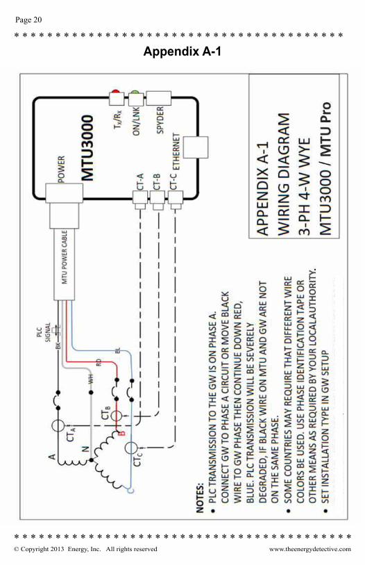
Appendix A-1
© Copyright 2013 Energy, Inc. All rights reserved www.theenergydetective.com
* * * * * * * * * * * * * * * * * * * * * * * * * * * * * * * * * * * * * * * *
* * * * * * * * * * * * * * * * * * * * * * * * * * * * * * * * * * * * * * * * *
* * * * * * * * * * * * * * * * * * * * * * * * * * * * * * * * * * * * * * * * *Page 21
* * * * * * * * * * * * * * * * * * * * * * * * * * * * * * * * * * * * * * * * *Rev 3.3
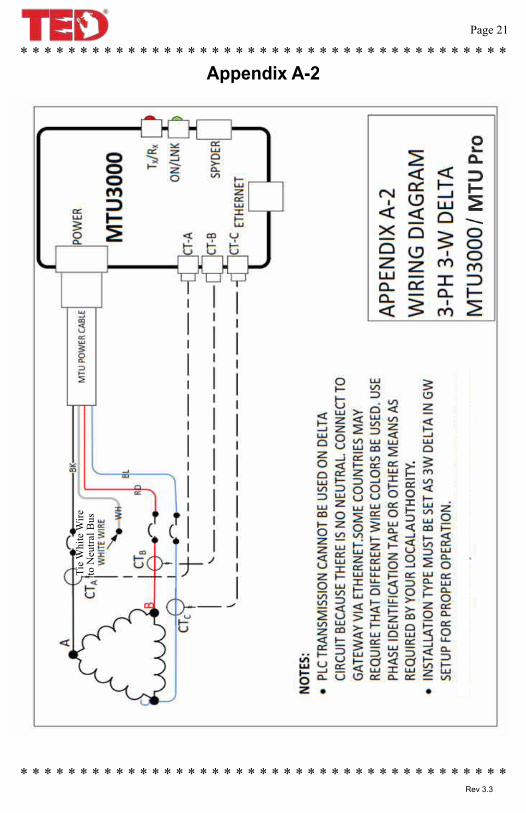
Appendix A-2Ti
e W
hite
Wire
to
Neu
tral B
us
© Copyright 2013 Energy, Inc. All rights reserved www.theenergydetective.com
Page 22
* * * * * * * * * * * * * * * * * * * * * * * * * * * * * * * * * * * * * * * *
* * * * * * * * * * * * * * * * * * * * * * * * * * * * * * * * * * * * * * * * *
* * * * * * * * * * * * * * * * * * * * * * * * * * * * * * * * * * * * * * * * *
* * * * * * * * * * * * * * * * * * * * * * * * * * * * * * * * * * * * * * * * *
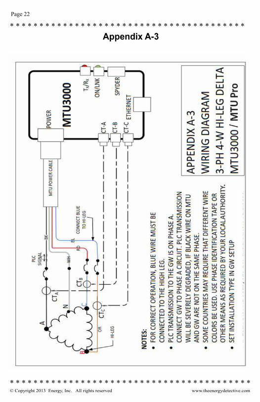
Appendix A-3
© Copyright 2013 Energy, Inc. All rights reserved www.theenergydetective.com
* * * * * * * * * * * * * * * * * * * * * * * * * * * * * * * * * * * * * * * *
* * * * * * * * * * * * * * * * * * * * * * * * * * * * * * * * * * * * * * * * *
* * * * * * * * * * * * * * * * * * * * * * * * * * * * * * * * * * * * * * * * *Page 23
* * * * * * * * * * * * * * * * * * * * * * * * * * * * * * * * * * * * * * * * *Rev 3.3
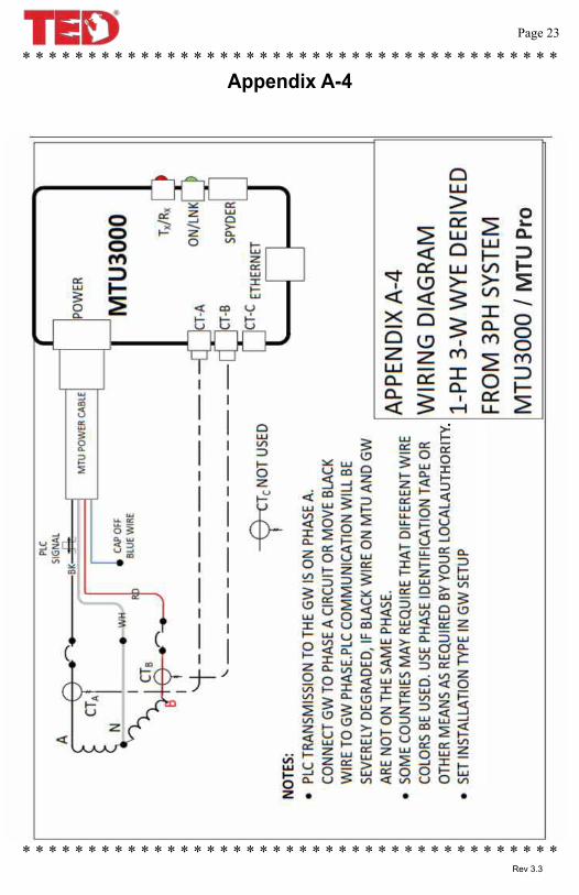
Appendix A-4
© Copyright 2013 Energy, Inc. All rights reserved www.theenergydetective.com
Page 24
* * * * * * * * * * * * * * * * * * * * * * * * * * * * * * * * * * * * * * * *
* * * * * * * * * * * * * * * * * * * * * * * * * * * * * * * * * * * * * * * * *
* * * * * * * * * * * * * * * * * * * * * * * * * * * * * * * * * * * * * * * * *
* * * * * * * * * * * * * * * * * * * * * * * * * * * * * * * * * * * * * * * * *
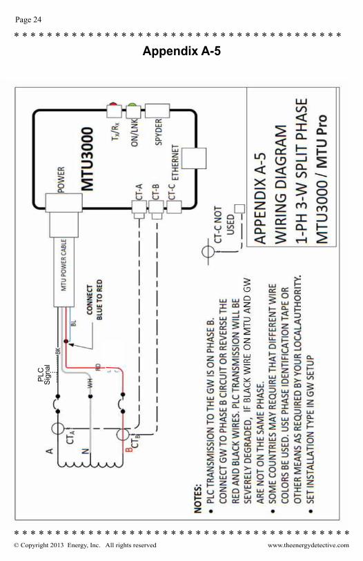
Appendix A-5P
LCS
igna
l

© Copyright 2013 Energy, Inc. All rights reserved www.theenergydetective.com
* * * * * * * * * * * * * * * * * * * * * * * * * * * * * * * * * * * * * * * *
* * * * * * * * * * * * * * * * * * * * * * * * * * * * * * * * * * * * * * * * *
* * * * * * * * * * * * * * * * * * * * * * * * * * * * * * * * * * * * * * * * *Page 25
* * * * * * * * * * * * * * * * * * * * * * * * * * * * * * * * * * * * * * * * *Rev 3.3
ROGOWSKI COIL OPTION: Rogowski coils are flexible CT “ropes” that allow for connecting around multiple conductors or even around bus bars.
1. The Rogowski MTU options available from TED have specially modified in-puts to accommodate the output from the Rogowski Coils. Care should be taken that standard CTs are not connected to Rogowski MTUs, this could cause irreversible damage to the MTU.
2. The MTUs are calibrated to the coils with which they are shipped. Each coil is marked by phase and must be connected in the proper CT input. (A Black, B RED, C BLUE).
3. Position arrow so it correctly shows flow of current.
4. Verify the Rogowski checkbox on the MTU UI has been selected for proper readings.
2000A coil is 24”. 5000A coil is 36”.
See the Energy Inc. website for availability: http://www.theenergydetective.com
Appendix B
© Copyright 2013 Energy, Inc. All rights reserved www.theenergydetective.com
Page 26
* * * * * * * * * * * * * * * * * * * * * * * * * * * * * * * * * * * * * * * *
* * * * * * * * * * * * * * * * * * * * * * * * * * * * * * * * * * * * * * * * *
* * * * * * * * * * * * * * * * * * * * * * * * * * * * * * * * * * * * * * * * *
* * * * * * * * * * * * * * * * * * * * * * * * * * * * * * * * * * * * * * * * *
Appendix CMTU Firmware Update Instructions
Only perform updates when required or a particular new feature is needed. MTU and ECC files must be compatible. Consult TED website or support with any questions before updating.
MTU Pro updates are performed through the MTU Ethernet port.
Caution: Some firmware updates will reset settings including network configuration. If network settings are reset to defaults, the network configuration will be DHCP, default IP will return to 192.168.7.3
Procedure:1. MTU firmware and User Interface files will be in the format: “MTU3K_date_revision.bin” and “MTU3000UI-date-revision.bin”2. Save files to a convenient location on computer.3. From the MTU UI page, select Update Firmware.4. Browse to the MTU3K firmware file, select and click Upload Firmware.5. WAIT 2 MINUTES after file is uploaded while firmware is written to
memory before proceeding.6. Select Update Firmware and repeat upload for the MTU3000UI file.

© Copyright 2013 Energy, Inc. All rights reserved www.theenergydetective.com
* * * * * * * * * * * * * * * * * * * * * * * * * * * * * * * * * * * * * * * *
* * * * * * * * * * * * * * * * * * * * * * * * * * * * * * * * * * * * * * * * *
* * * * * * * * * * * * * * * * * * * * * * * * * * * * * * * * * * * * * * * * *Page 27
* * * * * * * * * * * * * * * * * * * * * * * * * * * * * * * * * * * * * * * * *Rev 3.3
Notes

© Copyright 2013 Energy, Inc. All rights reserved www.theenergydetective.com * * * * * * * * * * * * * * * * * * * * * * * * * * * * * * * * * * * *
648 Marina DriveCharleston, South Carolina
29492(843) 766-9800(800) 959-5833
www.theenergydetective.com
ENERGY INC.