Embed Size (px)
Citation preview
2011-2012 RADITEK TELECOM GROUP
SHORT FORM CATALOG
Contact us at:
1702L Meridian Ave Suite 127 San Jose, CA 95125, USA
(408) 266-7404 HQ (408) 266-4483 Fax
http://www.raditek.com/#telecommunications Please send inquiries to: [email protected]

Print Date: 01/10/12
SATCOM BUCs C bands to >60W X bands to >50W Ku bands to >50W Ka bands to 50W Phase Locked LNBs IP/data Modems BUCs & Transceivers
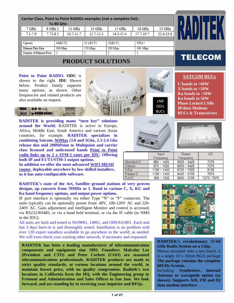
Carrier Class, Point to Point RADIOs examples (not a complete list):‐ To 80 GHz:
PRODUCT SOLUTIONS
RADITEK’s revolutionary 57-64 GHz Radio System on a Chip. Shown mounted onto a test board, it is a single 10 x 10mm BGA package The package contains the complete 60GHz System, Including: Synthesizer, internal Antenna or waveguide option (as shown). Supports AM, FM and IQ data modem interface.
Point to Point RADIO. ODU is shown to the right. IDU Shown below. Product family supports many options, as shown. Other frequencies and related products are also available on request.
LNB ODU BUCs
RADITEK’s state of the Art, Satellite ground stations of very proven designs, up converts from 70MHz or L Band to various C, X, KU and Ka band frequency options, and output power options. IF port interface is optionally via either Type “N” or “F” connector. The units typically can be optionally power from: 48V, 100-120V AC and 220-240V AC. Gain adjustment and intelligent Monitor and control is accessed, via RS232/RS485, or via a hand held terminal, or via the IF cable (to NMS in the IDU). All units are built and tested to ISO9001, 14001, and OHSAS1801. Each unit has 3 days burn-in is and thoroughly tested. Installation is no problem with over 120 expert installers available to go anywhere in the world, as needed. We will even check your existing other network, if necessary and requested.
RADITEK is providing many “turn key” solutions around the World. RADITEK is active in Europe, Africa, Middle East, South America and various Asian countries, for example. RADITEK specializes in combining Satcom, WiMax (3.8 and 5Ghz, 2.3-2.4 Ghz release due mid 2009)Point to Multipoint and carrier class licensed and unlicensed bands Point to Point radio links up to 2 x STM-1 rates per IDU. Offering both IP and E1/T1/STM-1 output options. In addition we offer the most advanced WIFI MESH router, deployable anywhere by low skilled installers, as it has auto-configurable software.
RADITEK has been a leading manufacturer of telecommunication components and equipment sine 1993. Founders: Malcolm Lee (President and CTO) and Peter Corbett (COO) are seasoned telecommunications professionals. RADITEK products are made to strict quality standards, at various locations around the world, to maintain lowest price, with no quality compromise. Raditek’s two locations in California form the HQ, with the Engineering group in Fremont and Administration and Sales Offices in San Jose. We look forward, and are standing by to receiving your inquiries and RFQs.
1 of 27
RADITEK INC.
MOST ADVANCED IP based Satellite network solution
IP Based Satellite Network Solution Specifications may be subject to change 12/13/10 WORLD HQ: 1702L Meridian Ave. Suite 127, San Jose, Ca 95125, U.S.A.
Tel: (408) 266-7404 FAX: (408) 266-4483 WEB: www.raditek.com E-mail: [email protected]
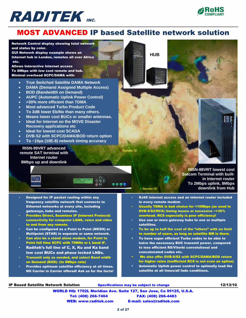
Network Control display showing total network and status by color. GUI Network display example shows an Internet hub in London, remotes all over Africa etc. Allows Interactive Internet access To 8Mbps with low cost remote and hub. Minimal overhead SCPC/DAMA with:
RISN-88VRT lowest cost Satcom Terminal with built-
in Internet router To 2Mbps uplink, 8Mbps
downlink from Hub
RISN-99VRT advanced remote SAT terminal with
Internet router 8Mbps up and downlink
• Designed for IP packet routing within any frequency satellite network that connects to Ethernet networks at every site, including gateways, hubs and remotes.
• Provides Direct, Seamless IP (Internet Protocol) connectivity for computer LANS, voice and video to and from any remote.
• Can be configured as a Point to Point (MESH) or Multipoint (STAR) in separate or same network.
• Can also be a stand alone modem, for Point to Point full time SCPC with 70MHz or L band IF.
• Raditek’s full line of C, X, Ku and Ka band low cost BUCs and phase locked LNBs.
• Transmit only as needed, and select Band width on Demand (BOD)- (to 8Mbps rate)
• Provides optimum satellite efficiency at all times. NO Carrier in Carrier offered! Ask us for the facts!
• RJ45 internet access and an internet router included in every remote modem
• Usually TDMA is bad choice for <10Mbps (as used in DVB-S/S2/RCS) timing issues or excessive ~>30% overhead. RCS especially is poor efficiency!
• Use one or more gateway hubs to one or multiple satellites.
• To be up to half the cost of the “others” with no limit to number of users, as long as satellite BW is there.
• To have super efficient Turbo codes to be able to halve the necessary BUC transmit power, compared to less efficient RS/Viterbi convolutional and concatenated codes etc.
• We also offer DVB-S/S2 with SCPC/DAMA/BOD return for higher rates (inefficient RCS is not even an option)
• Automatic Uplink power control to optimally load the satellite at all times/all fade conditions.
True Switched Satellite DAMA Network DAMA (Demand Assigned Multiple Access) BOD (Bandwidth on Demand) AUPC (Automatic Uplink Power Control) >30% more efficient than TDMA Most advanced Turbo Product Code To 3dB lower Eb/No than many others. Means lower cost BUCs or smaller antennas. Ideal for Internet on the MOVE Disaster
Recovery applications etc Ideal for lowest cost SCADA DVB-S2 with SCPC/DAMA/BOD return option To ~10µs (10E-8) network timing accuracy
HUB
2 of 27
RADITEK INC.
MOST ADVANCED IP based Satellite network solution
IP Based Satellite Network Solution Specifications may be subject to change 12/13/10 WORLD HQ: 1702L Meridian Ave. Suite 127, San Jose, Ca 95125, U.S.A.
Tel: (408) 266-7404 FAX: (408) 266-4483 WEB: www.raditek.com E-mail: [email protected]
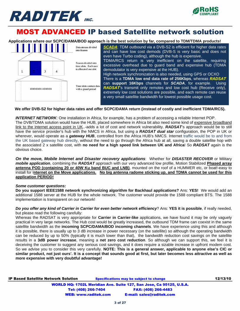
Applications where our SCPC/DAMA/BOD approach is the best solution by far, compared to TDM/TDMA products!
We offer DVB-S2 for higher data rates and offer SCPC/DAMA return (instead of costly and inefficient TDMA/RCS).
INTERNET NETWORK: One installation in Africa, for example, has a problem of accessing a reliable Internet POP. The DVB/TDMA solution would have the HUB, placed somewhere in Africa bit also need some kind of expensive broadband link to the internet access point in UK..-adds a lot of cost and network vulnerability. RADSAT’s approach would be to still have the service provider’s hub with the NMCS in Africa, but using a RADSAT dual star configuration, the POP in UK or wherever, would operate as a gateway HUB, controlled from the Africa HUB’s NMCS. Internet traffic would be to and from the UK based gateway hub directly, without the need to go through the Africa hub at all, saving a double satellite hop with the associated 2 x satellite cost, with no need for a high speed link between UK and Africa! So RADSAT again is the obvious choice. On the move, Mobile Internet and Disaster recovery applications: Whether for DISASTER RECOVER or Military mobile application, combining the RADSAT approach with our very advanced low profile, Motion Stabilized Phased array antenna POD (containing 20 or 40W Ku band BUC and LNB), mounted on the roof of a HUMMER etc, or boat!-easy to install for Internet on the Move applications. No big antenna radome sticking up, and TDMA cannot be used for this application PERIOD! Some customer questions: Do you support IEEE1588 network synchronizing algorithm for Backhaul applications? Ans: YES! We would add an additional 1588 server at the HUB for the whole network. The customer would provide the 1588 compliant BTS. The 1588 implementation is transparent on our network! Do you offer any kind of Carrier in Carrier for even better network efficiency? Ans: YES it is possible, if really needed, but please read the following carefully: Whereas the RADSAT is very appropriate for Carrier in Carrier-like applications, we have found it may be only vaguely practical in very large networks. The Hub cost would be greatly increased, the outbound TDM frame can coexist in the same satellite bandwidth as the incoming SCPC/DAMA/BOD incoming channels. We have experience using this and although it is possible, there is usually up to 3 dB increase in power necessary (on the satellite) so although the operating bandwidth can be reduced by up to 50% (typically it is much lower than that), the bandwidth reduction cost savings on the satellite results in a 3dB power increase, meaning a net zero cost reduction. So although we can support this, we feel it is deceiving the customer to suggest any serious cost savings, and it does require a sizable increase in upfront modem cost. So we advise you to consider this very carefully. NOTE: This is a general answer, applicable to anyone else’s CIC or similar product, not just ours’. It is a concept that sounds good at first, but later becomes less attractive as well as more expensive with very doubtful advantage!
SCADA: TDM outbound via a DVB-S2 is efficient for higher data rates and can have low cost demods (DVB-S is very basic and does not even have Turbo coding), although the hub is expensive. TDMA/RCS return is very inefficient on the satellite, requiring excessive overhead due to guard band and expensive hub (TDMA demodulator is very expensive at the HUB). High network synchronization is also needed, using GPS or OCXO There is a TDMA low end data rate of 256Kbps, whereas RADSAT can support 16Kbps channels for SCADA, for example. Using RADSAT’s transmit only remotes and low cost hub (Receive only), extremely low cost solutions are possible, and each remote can reuse a very small satellite bandwidth for lowest possible usage cost.
3 of 27
RADITEK INC.
MOST ADVANCED IP based Satellite network solution
IP Based Satellite Network Solution Specifications may be subject to change 12/13/10 WORLD HQ: 1702L Meridian Ave. Suite 127, San Jose, Ca 95125, U.S.A.
Tel: (408) 266-7404 FAX: (408) 266-4483 WEB: www.raditek.com E-mail: [email protected]
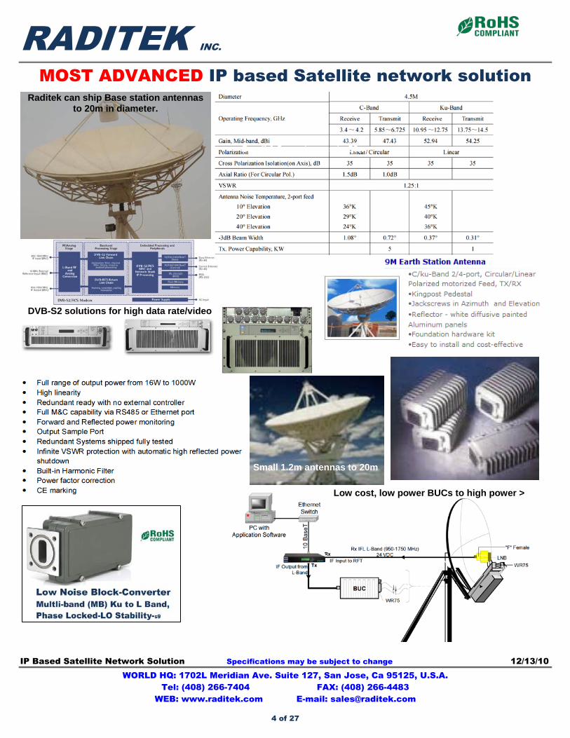
DVB-S2 solutions for high data rate/video
Raditek can ship Base station antennasto 20m in diameter.
Small 1.2m antennas to 20m
Low cost, low power BUCs to high power >
Small 1.2m antennas to 20m
4 of 27
RBUC-C-L-N-2-250W-15-220V- Generic-h1 Specifications may be subject to change 05/20/10 WORLD HQ: 1702L Meridian Ave. Suite 127, San Jose, Ca 95125, U.S.A.
Tel: (408) 266-7404 FAX: (408) 266-4483 WEB: www.raditek.com E-mail: [email protected]
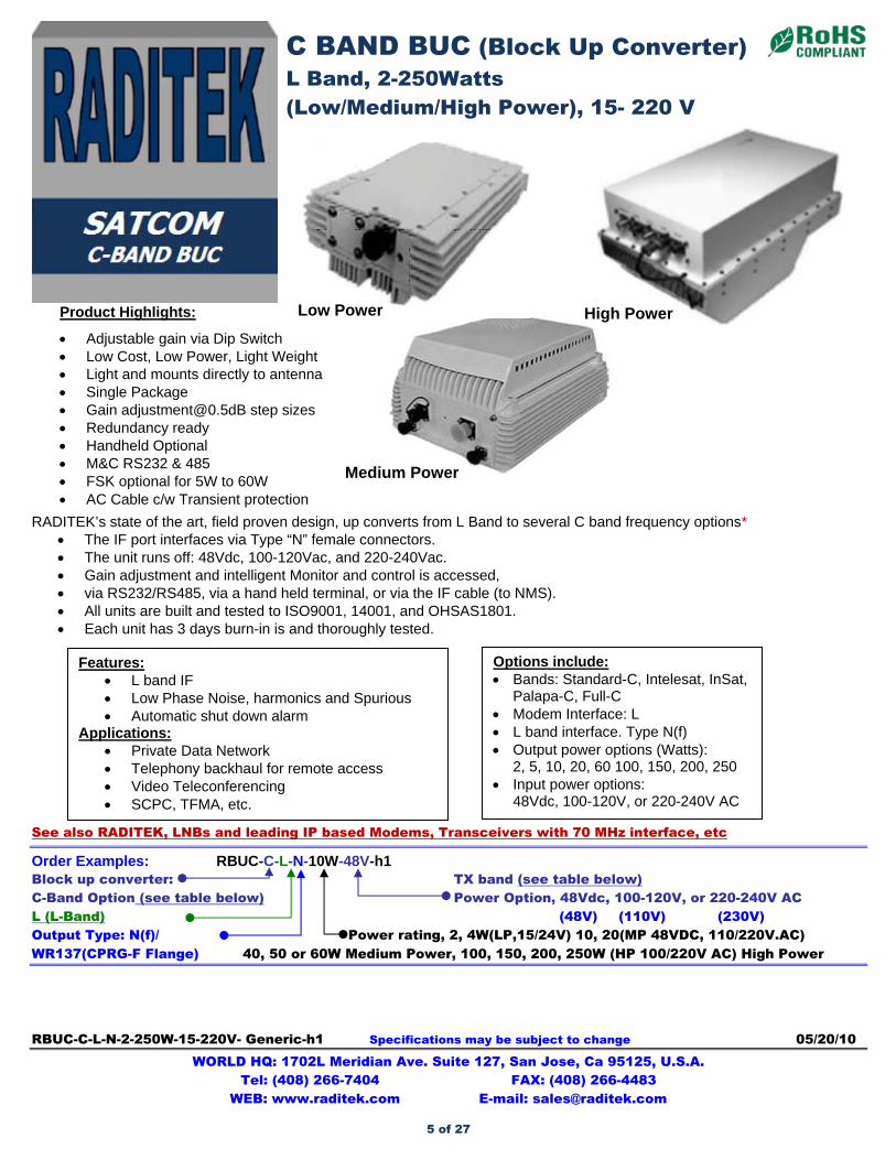
RADITEK’s state of the art, field proven design, up converts from L Band to several C band frequency options*
The IF port interfaces via Type “N” female connectors. The unit runs off: 48Vdc, 100-120Vac, and 220-240Vac. Gain adjustment and intelligent Monitor and control is accessed, via RS232/RS485, via a hand held terminal, or via the IF cable (to NMS). All units are built and tested to ISO9001, 14001, and OHSAS1801. Each unit has 3 days burn-in is and thoroughly tested.
See also RADITEK, LNBs and leading IP based Modems, Transceivers with 70 MHz interface, etc
Order Examples: RBUC-C-L-N-10W-48V-h1 Block up converter: TX band (see table below) C-Band Option (see table below) Power Option, 48Vdc, 100-120V, or 220-240V AC L (L-Band) (48V) (110V) (230V) Output Type: N(f)/ Power rating, 2, 4W(LP,15/24V) 10, 20(MP 48VDC, 110/220V.AC) WR137(CPRG-F Flange) 40, 50 or 60W Medium Power, 100, 150, 200, 250W (HP 100/220V AC) High Power
Medium Power
Product Highlights:
Adjustable gain via Dip Switch Low Cost, Low Power, Light Weight Light and mounts directly to antenna Single Package Gain [email protected] step sizes Redundancy ready Handheld Optional M&C RS232 & 485 FSK optional for 5W to 60W AC Cable c/w Transient protection
Low Power High Power
C BAND BUC (Block Up Converter) L Band, 2-250Watts (Low/Medium/High Power), 15- 220 V
Options include: Bands: Standard-C, Intelesat, InSat,
Palapa-C, Full-C Modem Interface: L L band interface. Type N(f) Output power options (Watts):
2, 5, 10, 20, 60 100, 150, 200, 250 Input power options:
48Vdc, 100-120V, or 220-240V AC
Features: L band IF Low Phase Noise, harmonics and Spurious Automatic shut down alarm
Applications: Private Data Network Telephony backhaul for remote access Video Teleconferencing SCPC, TFMA, etc.
5 of 27
RADITEK INC.
C BAND BUC (Block Up Converter), L Band code-h1
2-250Watts (Low/Medium/High Power), 15- 220 V
RBUC-C-L-N-2-250W-15-220V- Generic-h1 Specifications may be subject to change 05/20/10 WORLD HQ: 1702L Meridian Ave. Suite 127, San Jose, Ca 95125, U.S.A.
Tel: (408) 266-7404 FAX: (408) 266-4483 WEB: www.raditek.com E-mail: [email protected]
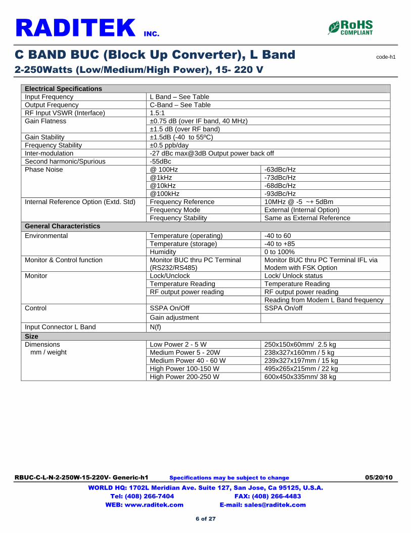
Electrical Specifications Input Frequency L Band – See Table Output Frequency C-Band – See Table RF Input VSWR (Interface) 1.5:1
±0.75 dB (over IF band, 40 MHz) Gain Flatness ±1.5 dB (over RF band)
Gain Stability ±1.5dB (-40 to 55ºC) Frequency Stability ±0.5 ppb/day Inter-modulation -27 dBc max@3dB Output power back off Second harmonic/Spurious -55dBc
@ 100Hz -63dBc/Hz @1kHz -73dBc/Hz @10kHz -68dBc/Hz
Phase Noise
@100kHz -93dBc/Hz Frequency Reference 10MHz @ -5 ~+ 5dBm Frequency Mode External (Internal Option)
Internal Reference Option (Extd. Std)
Frequency Stability Same as External Reference General Characteristics
Temperature (operating) -40 to 60 Temperature (storage) -40 to +85
Environmental
Humidity 0 to 100% Monitor & Control function Monitor BUC thru PC Terminal
(RS232/RS485) Monitor BUC thru PC Terminal IFL via Modem with FSK Option
Lock/Unclock Lock/ Unlock status Temperature Reading Temperature Reading RF output power reading RF output power reading
Monitor
Reading from Modem L Band frequency SSPA On/Off SSPA On/off Control
Gain adjustment
Input Connector L Band N(f)
Size Low Power 2 - 5 W 250x150x60mm/ 2.5 kg Medium Power 5 - 20W 238x327x160mm / 5 kg Medium Power 40 - 60 W 239x327x197mm / 15 kg High Power 100-150 W 495x265x215mm / 22 kg
Dimensions mm / weight
High Power 200-250 W 600x450x335mm/ 38 kg
6 of 27
RADITEK INC.
C BAND BUC (Block Up Converter), L Band code-h1
2-250Watts (Low/Medium/High Power), 15- 220 V
RBUC-C-L-N-2-250W-15-220V- Generic-h1 Specifications may be subject to change 05/20/10 WORLD HQ: 1702L Meridian Ave. Suite 127, San Jose, Ca 95125, U.S.A.
Tel: (408) 266-7404 FAX: (408) 266-4483 WEB: www.raditek.com E-mail: [email protected]
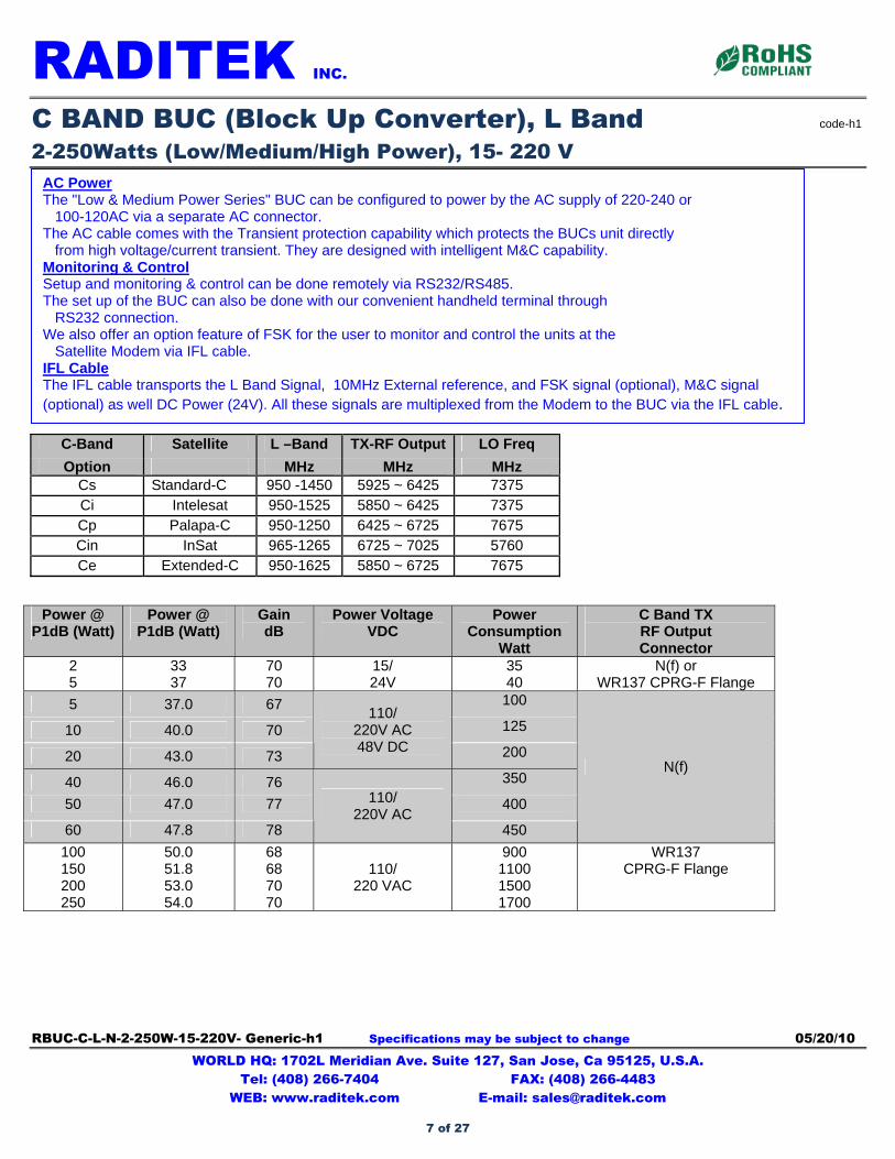
C-Band Satellite L –Band TX-RF Output LO Freq
Option MHz MHz MHz Cs Standard-C 950 -1450 5925 ~ 6425 7375 Ci Intelesat 950-1525 5850 ~ 6425 7375 Cp Palapa-C 950-1250 6425 ~ 6725 7675 Cin InSat 965-1265 6725 ~ 7025 5760 Ce Extended-C 950-1625 5850 ~ 6725 7675
Power @
P1dB (Watt) Power @
P1dB (Watt) Gain dB
Power Voltage VDC
Power Consumption
Watt
C Band TX RF Output Connector
2 5
33 37
70 70
15/ 24V
35 40
N(f) or WR137 CPRG-F Flange
5 37.0 67 100
10 40.0 70 125
20 43.0 73
110/ 220V AC 48V DC 200
40 46.0 76 350
50 47.0 77 400
60 47.8 78
110/ 220V AC
450
N(f)
100 150 200 250
50.0 51.8 53.0 54.0
68 68 70 70
110/ 220 VAC
900 1100 1500 1700
WR137 CPRG-F Flange
AC Power The "Low & Medium Power Series" BUC can be configured to power by the AC supply of 220-240 or 100-120AC via a separate AC connector. The AC cable comes with the Transient protection capability which protects the BUCs unit directly from high voltage/current transient. They are designed with intelligent M&C capability. Monitoring & Control Setup and monitoring & control can be done remotely via RS232/RS485. The set up of the BUC can also be done with our convenient handheld terminal through RS232 connection. We also offer an option feature of FSK for the user to monitor and control the units at the Satellite Modem via IFL cable. IFL Cable The IFL cable transports the L Band Signal, 10MHz External reference, and FSK signal (optional), M&C signal (optional) as well DC Power (24V). All these signals are multiplexed from the Modem to the BUC via the IFL cable.
7 of 27
RLNB-C-L-N-PLL-h1 Specifications may be subject to change 05/12/10 WORLD HQ: 1702L Meridian Ave. Suite 127, San Jose, Ca 95125, U.S.A.
Tel: (408) 266-7404 FAX: (408) 266-4483 WEB: www.raditek.com E-mail: [email protected]
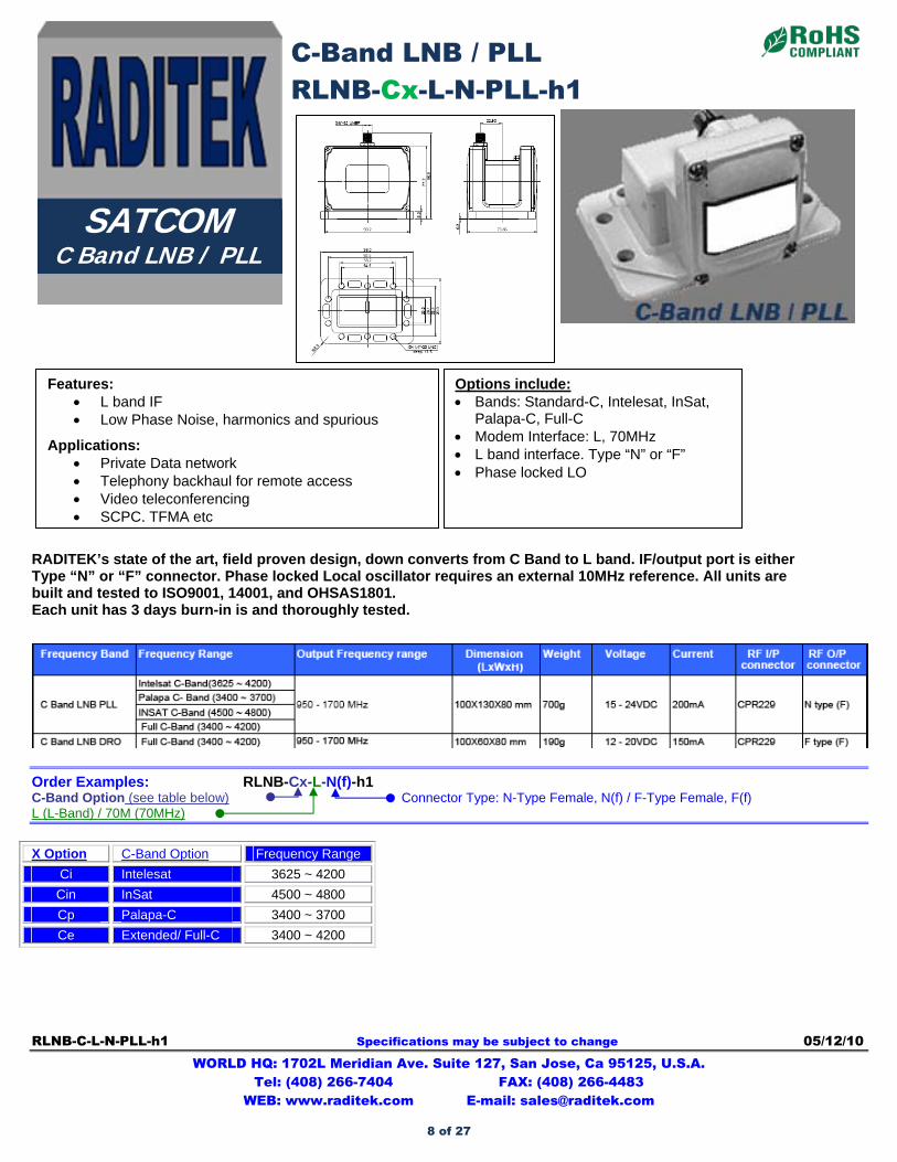
RADITEK’s state of the art, field proven design, down converts from C Band to L band. IF/output port is either Type “N” or “F” connector. Phase locked Local oscillator requires an external 10MHz reference. All units are built and tested to ISO9001, 14001, and OHSAS1801. Each unit has 3 days burn-in is and thoroughly tested.
Order Examples: RLNB-Cx-L-N(f)-h1 C-Band Option (see table below) Connector Type: N-Type Female, N(f) / F-Type Female, F(f) L (L-Band) / 70M (70MHz)
X Option C-Band Option Frequency Range
Ci Intelesat 3625 ~ 4200
Cin InSat 4500 ~ 4800
Cp Palapa-C 3400 ~ 3700
Ce Extended/ Full-C 3400 ~ 4200
C-Band LNB / PLL RLNB-Cx-L-N-PLL-h1
SATCOM C Band LNB / PLL
Options include: Bands: Standard-C, Intelesat, InSat,
Palapa-C, Full-C Modem Interface: L, 70MHz L band interface. Type “N” or “F” Phase locked LO
Features: L band IF Low Phase Noise, harmonics and spurious
Applications: Private Data network Telephony backhaul for remote access Video teleconferencing SCPC, TFMA etc
8 of 27
RADITEK INC.
C-Band LNB / PLL code-h1
RLNB-Cx-L-N-PLL-h1
RLNB-C-L-N-PLL-h1 Specifications may be subject to change 05/12/10 WORLD HQ: 1702L Meridian Ave. Suite 127, San Jose, Ca 95125, U.S.A.
Tel: (408) 266-7404 FAX: (408) 266-4483 WEB: www.raditek.com E-mail: [email protected]
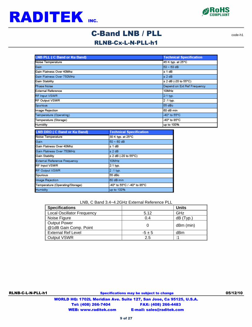
LNB, C Band 3.4~4.2GHz External Reference PLL Specifications Units Local Oscillator Frequency 5.12 GHz Noise Figure 0.4 dB (Typ.) Output Power @1dB Gain Comp. Point
0 dBm (min)
External Ref Level -5 ± 5 dBm Output VSWR 2.5 :1
9 of 27
RTR-C-70M-N-2-250W-h1 Specifications may be subject to change 05/20/10 WORLD HQ: 1702L Meridian Ave. Suite 127, San Jose, Ca 95125, U.S.A.
Tel: (408) 266-7404 FAX: (408) 266-4483 WEB: www.raditek.com E-mail: [email protected]
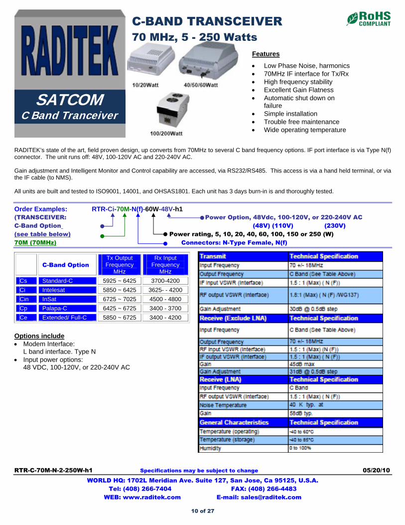
RADITEK’s state of the art, field proven design, up converts from 70MHz to several C band frequency options. IF port interface is via Type N(f) connector. The unit runs off: 48V, 100-120V AC and 220-240V AC. Gain adjustment and Intelligent Monitor and Control capability are accessed, via RS232/RS485. This access is via a hand held terminal, or via the IF cable (to NMS). All units are built and tested to ISO9001, 14001, and OHSAS1801. Each unit has 3 days burn-in is and thoroughly tested.
Order Examples: RTR-Ci-70M-N(f)-60W-48V-h1 (TRANSCEIVER: Power Option, 48Vdc, 100-120V, or 220-240V AC C-Band Option (48V) (110V) (230V) (see table below) Power rating, 5, 10, 20, 40, 60, 100, 150 or 250 (W) 70M (70MHz) Connectors: N-Type Female, N(f)
C-Band Option
Tx Output Frequency
MHz
Rx Input Frequency
MHz
Cs Standard-C 5925 ~ 6425 3700-4200
Ci Intelesat 5850 ~ 6425 3625- - 4200
Cin InSat 6725 ~ 7025 4500 - 4800
Cp Palapa-C 6425 ~ 6725 3400 - 3700
Ce Extended/ Full-C 5850 ~ 6725 3400 - 4200
Options include Modem Interface:
L band interface. Type N Input power options:
48 VDC, 100-120V, or 220-240V AC
Features
Low Phase Noise, harmonics 70MHz IF interface for Tx/Rx High frequency stability Excellent Gain Flatness Automatic shut down on
failure Simple installation Trouble free maintenance Wide operating temperature
C-BAND TRANSCEIVER 70 MHz, 5 - 250 Watts
SATCOM C Band Tranceiver
10 of 27
RADITEK INC.
C-BAND TRANSCEIVER, 70 MHz, 5 - 250 Watts code-h1
L-Band, 2-80Watts
RTR-C-70M-N-2-250W-h1 Specifications may be subject to change 05/20/10 WORLD HQ: 1702L Meridian Ave. Suite 127, San Jose, Ca 95125, U.S.A.
Tel: (408) 266-7404 FAX: (408) 266-4483 WEB: www.raditek.com E-mail: [email protected]
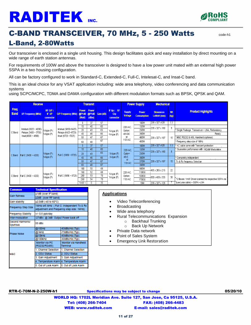
Our transceiver is enclosed in a single unit housing. This design facilitates quick and easy installation by direct mounting on a wide range of earth station antennas.
For requirements of 100W and above the transceiver is designed to have a low power unit mated with an external high power SSPA in a two housing configuration.
All can be factory configured to work in Standard-C, Extended-C, Full-C, Intelesat-C, and Insat-C band.
This is an ideal choice for any VSAT application including: wide area telephony, video conferencing and data communication systems using SCPC/MCPC, TDMA and DAMA configuration with different modulation formats such as BPSK, QPSK and QAM.
Applications
Video Teleconferencing Broadcasting Wide area telephony Rural Telecommunications Expansion
o Backhaul Trunking o Back Up Network
Private Data network Point of Sales System Emergency Link Restoration
11 of 27
RBUC-Ku-L-N-2-80W-h1 Specifications may be subject to change 05/20/10 WORLD HQ: 1702L Meridian Ave. Suite 127, San Jose, Ca 95125, U.S.A.
Tel: (408) 266-7404 FAX: (408) 266-4483 WEB: www.raditek.com E-mail: [email protected]
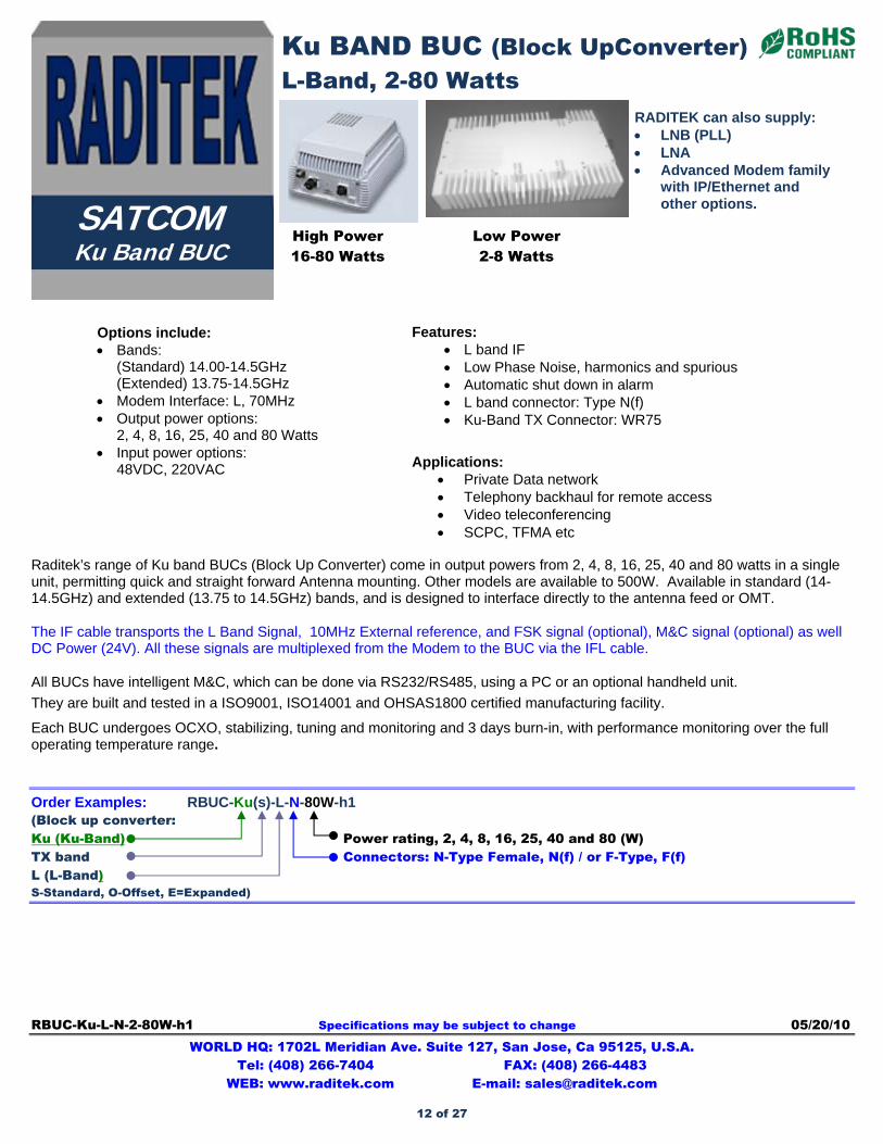
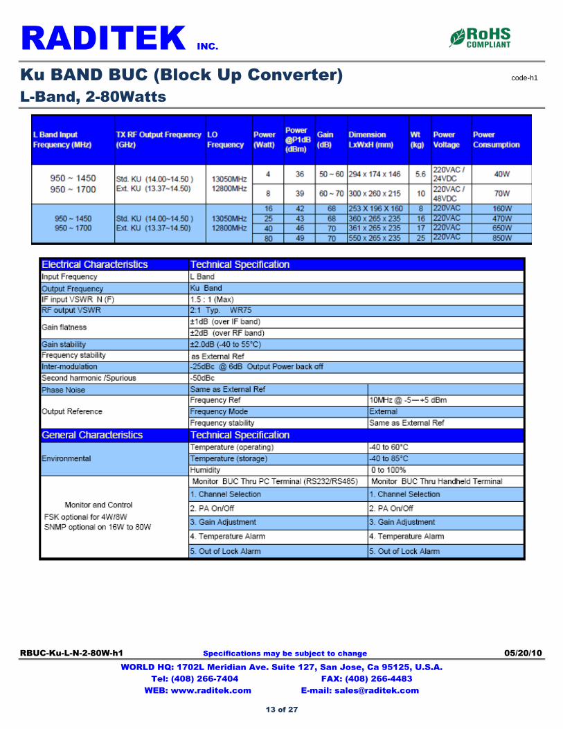
Raditek’s range of Ku band BUCs (Block Up Converter) come in output powers from 2, 4, 8, 16, 25, 40 and 80 watts in a single unit, permitting quick and straight forward Antenna mounting. Other models are available to 500W. Available in standard (14-14.5GHz) and extended (13.75 to 14.5GHz) bands, and is designed to interface directly to the antenna feed or OMT.
The IF cable transports the L Band Signal, 10MHz External reference, and FSK signal (optional), M&C signal (optional) as well DC Power (24V). All these signals are multiplexed from the Modem to the BUC via the IFL cable.
All BUCs have intelligent M&C, which can be done via RS232/RS485, using a PC or an optional handheld unit.
They are built and tested in a ISO9001, ISO14001 and OHSAS1800 certified manufacturing facility.
Each BUC undergoes OCXO, stabilizing, tuning and monitoring and 3 days burn-in, with performance monitoring over the full operating temperature range.
Order Examples: RBUC-Ku(s)-L-N-80W-h1 (Block up converter: Ku (Ku-Band) Power rating, 2, 4, 8, 16, 25, 40 and 80 (W) TX band Connectors: N-Type Female, N(f) / or F-Type, F(f) L (L-Band) S-Standard, O-Offset, E=Expanded)
RADITEK can also supply: LNB (PLL) LNA Advanced Modem family
with IP/Ethernet and other options.
Ku BAND BUC (Block UpConverter) L-Band, 2-80 Watts
High Power 16-80 Watts
Low Power 2-8 Watts
SATCOM Ku Band BUC
Options include: Bands:
(Standard) 14.00-14.5GHz (Extended) 13.75-14.5GHz
Modem Interface: L, 70MHz Output power options:
2, 4, 8, 16, 25, 40 and 80 Watts Input power options:
48VDC, 220VAC
Features: L band IF Low Phase Noise, harmonics and spurious Automatic shut down in alarm L band connector: Type N(f) Ku-Band TX Connector: WR75
Applications: Private Data network Telephony backhaul for remote access Video teleconferencing SCPC, TFMA etc
12 of 27
RADITEK INC.
Ku BAND BUC (Block Up Converter) code-h1
L-Band, 2-80Watts
RBUC-Ku-L-N-2-80W-h1 Specifications may be subject to change 05/20/10 WORLD HQ: 1702L Meridian Ave. Suite 127, San Jose, Ca 95125, U.S.A.
Tel: (408) 266-7404 FAX: (408) 266-4483 WEB: www.raditek.com E-mail: [email protected]
13 of 27
RLNB-Ku-L-N-PLL-h1 Specifications may be subject to change 04/06/09 WORLD HQ: 1702L Meridian Ave. Suite 127, San Jose, Ca 95125, U.S.A.
Tel: (408) 266-7404 FAX: (408) 266-4483 WEB: www.raditek.com E-mail: [email protected]
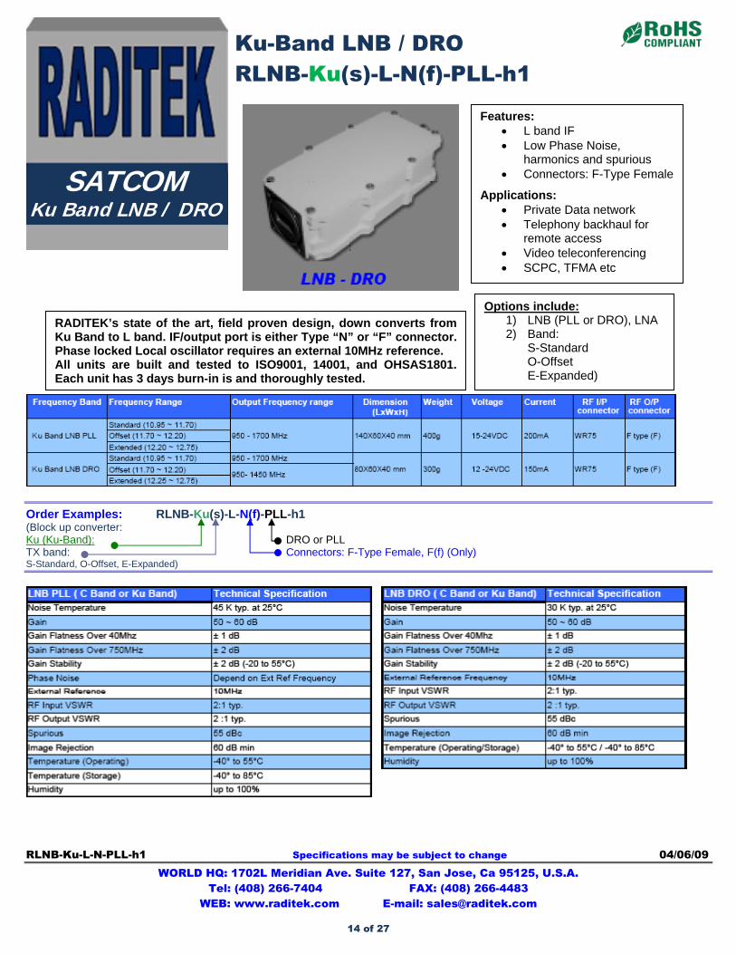
Order Examples: RLNB-Ku(s)-L-N(f)-PLL-h1 (Block up converter: Ku (Ku-Band): DRO or PLL TX band: Connectors: F-Type Female, F(f) (Only) S-Standard, O-Offset, E-Expanded)
Ku-Band LNB / DRO RLNB-Ku(s)-L-N(f)-PLL-h1
SATCOM Ku Band LNB / DRO
Options include: 1) LNB (PLL or DRO), LNA 2) Band:
S-Standard O-Offset E-Expanded)
Features: L band IF Low Phase Noise,
harmonics and spurious Connectors: F-Type Female
Applications: Private Data network Telephony backhaul for
remote access Video teleconferencing SCPC, TFMA etc
RADITEK’s state of the art, field proven design, down converts from Ku Band to L band. IF/output port is either Type “N” or “F” connector. Phase locked Local oscillator requires an external 10MHz reference. All units are built and tested to ISO9001, 14001, and OHSAS1801. Each unit has 3 days burn-in is and thoroughly tested.
14 of 27
RMOD-DVB-S2-RCS-opt modem-v8 Specifications may be subject to change 06/02/10 WORLD HQ: 1702L Meridian Ave. Suite 127, San Jose, Ca 95125, U.S.A.
Tel: (408) 266-7404 FAX: (408) 266-4483 WEB: www.raditek.com E-mail: [email protected]
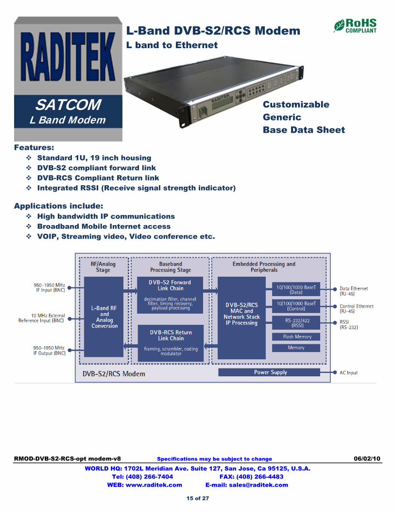
Features: Standard 1U, 19 inch housing DVB-S2 compliant forward link DVB-RCS Compliant Return link Integrated RSSI (Receive signal strength indicator)
Applications include: High bandwidth IP communications Broadband Mobile Internet access VOIP, Streaming video, Video conference etc.
L-Band DVB-S2/RCS Modem L band to Ethernet
SATCOM L Band Modem
Customizable Generic Base Data Sheet
15 of 27
RADITEK INC.
L-Band DVB-S2/RCS Modem code-v8
L band to Ethernet
RMOD-DVB-S2-RCS-opt modem-v8 Specifications may be subject to change 06/02/10 WORLD HQ: 1702L Meridian Ave. Suite 127, San Jose, Ca 95125, U.S.A.
Tel: (408) 266-7404 FAX: (408) 266-4483 WEB: www.raditek.com E-mail: [email protected]
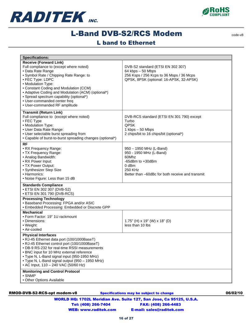
Specifications: Receive (Forward Link) Full compliance to (except where noted) • Data Rate Range • Symbol Rate / Chipping Rate Range: to • FEC Type: LDPC • Modulation Type: • Constant Coding and Modulation (CCM) • Adaptive Coding and Modulation (ACM) (optional*) • Spread spectrum capability (optional*) • User-commanded center freq • User-commanded RF amplitude
DVB-S2 standard (ETSI EN 302 307) 64 kbps – 50 Mbps 256 Ksps / 256 Kcps to 36 Msps / 36 Mcps QPSK, 8PSK (optional: 16-APSK, 32-APSK)
Transmit (Return Link) Full compliance to (except where noted) • FEC Type • Modulation Type: • User Data Rate Range: • User selectable burst spreading from • Capable of burst-to-burst spreading changes (optional*)
DVB-RCS standard (ETSI EN 301 790) except Turbo QPSK 1 kbps – 50 Mbps 2 chips/bit to 16 chips/bit (optional*)
RF • RX Frequency Range: • TX Frequency Range: • Analog Bandwidth: • RX Power Input: • TX Power Output: • Synthesizer Step Size • Harmonics: • Noise Figure: Less than 15 dB
950 – 1950 MHz (L-Band) 950 - 1950 MHz (L-Band) 60Mhz -65dBm to +30dBm 0 dBm 250 KHz Better than –60dBc for both receive and transmit
Standards Compliance • ETSI EN 302 307 (DVB-S2) • ETSI EN 301 790 (DVB-RCS) Processing Technology • Baseband Processing: FPGA and/or ASIC • Embedded Processing: Embedded or Discrete GPP Mechanical • Form Factor: 19” 1U rackmount • Dimensions: • Weight: • Air-cooled
1.75” (H) x 19” (W) x 18” (D) less than 10 lbs
Physical Interfaces • RJ-45 Ethernet data port (100/1000BaseT) • RJ-45 Ethernet control port (100/1000BaseT) • DB-9 RS-232 for real-time RSSI measurements • BNC input for 10 MHz external reference • Type N, L-Band signal input (950-1950 MHz) • Type N, L-Band signal output (950 – 1950 MHz) • AC Input, 110 – 240 VAC (50/60 Hz)
Monitoring and Control Protocol • SNMP • Other Options Available
16 of 27
RADITEK INC.
L-Band DVB-S2/RCS Modem code-v8
L band to Ethernet
RMOD-DVB-S2-RCS-opt modem-v8 Specifications may be subject to change 06/02/10 WORLD HQ: 1702L Meridian Ave. Suite 127, San Jose, Ca 95125, U.S.A.
Tel: (408) 266-7404 FAX: (408) 266-4483 WEB: www.raditek.com E-mail: [email protected]
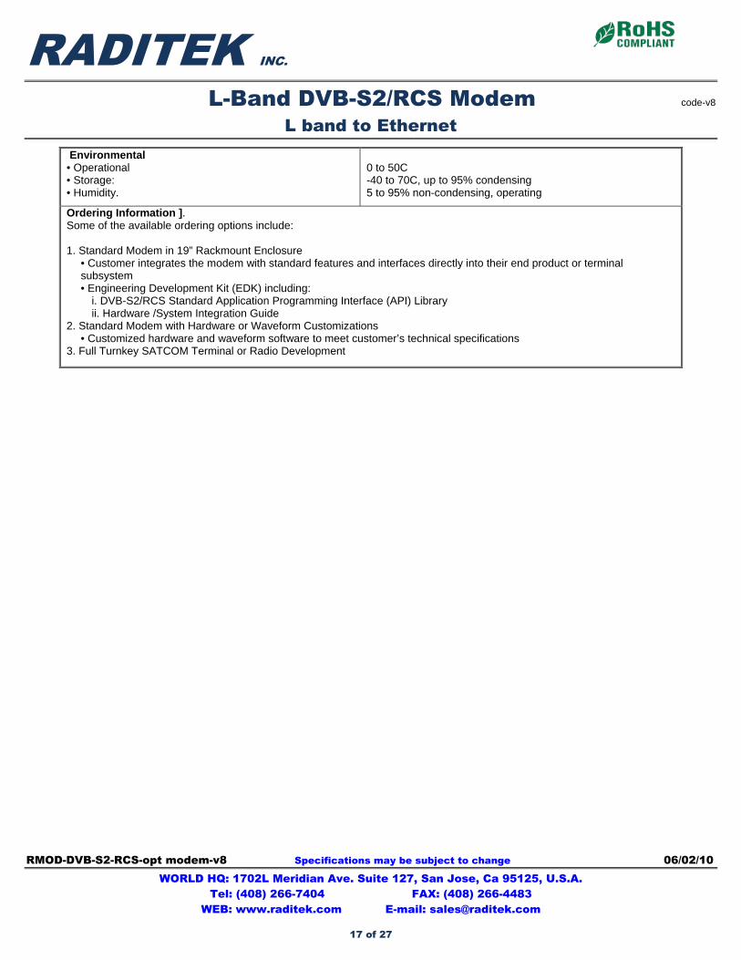
Environmental • Operational • Storage: • Humidity.
0 to 50C -40 to 70C, up to 95% condensing 5 to 95% non-condensing, operating
Ordering Information ]. Some of the available ordering options include: 1. Standard Modem in 19” Rackmount Enclosure
• Customer integrates the modem with standard features and interfaces directly into their end product or terminal subsystem • Engineering Development Kit (EDK) including:
i. DVB-S2/RCS Standard Application Programming Interface (API) Library ii. Hardware /System Integration Guide
2. Standard Modem with Hardware or Waveform Customizations • Customized hardware and waveform software to meet customer’s technical specifications
3. Full Turnkey SATCOM Terminal or Radio Development
17 of 27
RADTR-P2P-HC-6-38-E1-T1-a9 Specifications may be subject to change 10/08/09 WORLD HQ: 1702L Meridian Ave. Suite 127, San Jose, Ca 95125, U.S.A.
Tel: (408) 266-7404 FAX: (408) 266-4483 WEB: www.raditek.com E-mail: [email protected]
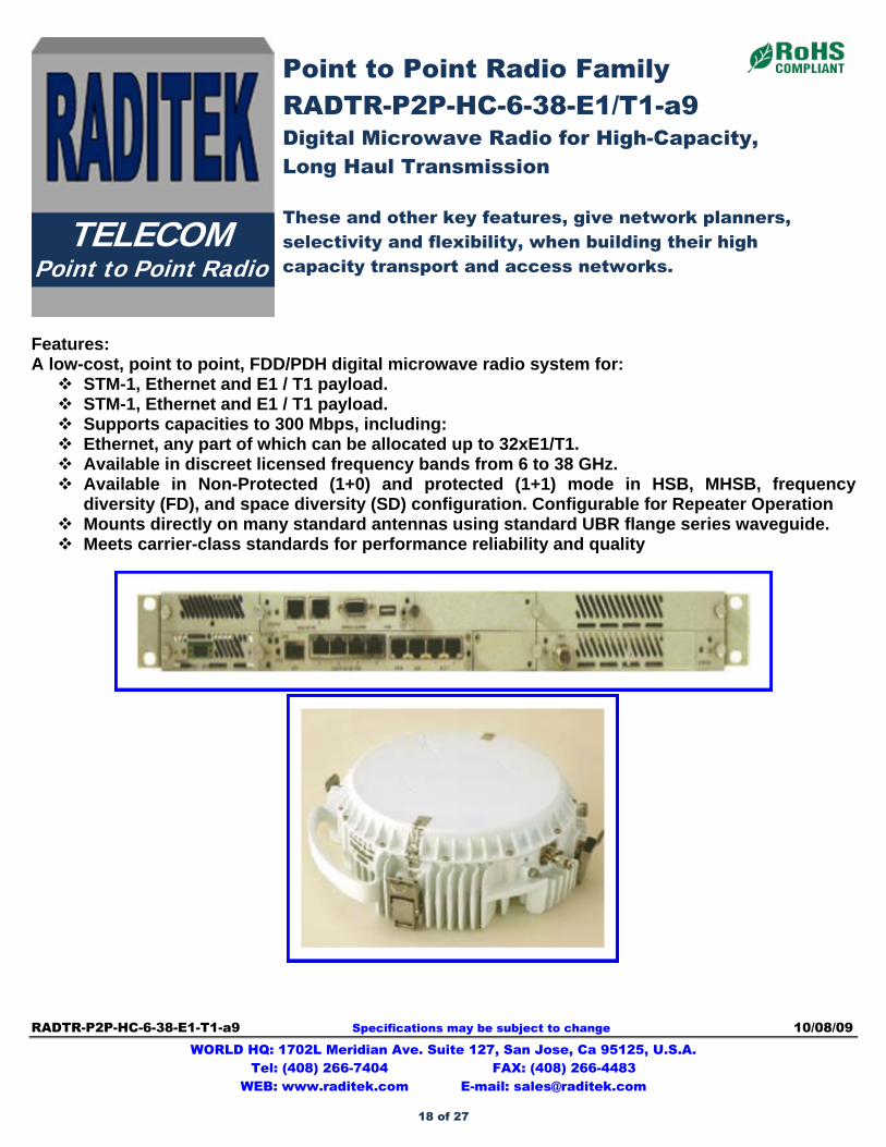
Features: A low-cost, point to point, FDD/PDH digital microwave radio system for: STM-1, Ethernet and E1 / T1 payload. STM-1, Ethernet and E1 / T1 payload. Supports capacities to 300 Mbps, including: Ethernet, any part of which can be allocated up to 32xE1/T1. Available in discreet licensed frequency bands from 6 to 38 GHz. Available in Non-Protected (1+0) and protected (1+1) mode in HSB, MHSB, frequency
diversity (FD), and space diversity (SD) configuration. Configurable for Repeater Operation Mounts directly on many standard antennas using standard UBR flange series waveguide. Meets carrier-class standards for performance reliability and quality
Point to Point Radio Family RADTR-P2P-HC-6-38-E1/T1-a9 Digital Microwave Radio for High-Capacity, Long Haul Transmission These and other key features, give network planners, selectivity and flexibility, when building their high capacity transport and access networks.
TELECOM Point to Point Radio
18 of 27
RADITEK INC.
Point to Point Radio Family code-a9
RADTR-P2P-HC-6-38-E1/T1-a9
RADTR-P2P-HC-6-38-E1-T1-a9 Specifications may be subject to change 10/08/09 WORLD HQ: 1702L Meridian Ave. Suite 127, San Jose, Ca 95125, U.S.A.
Tel: (408) 266-7404 FAX: (408) 266-4483 WEB: www.raditek.com E-mail: [email protected]
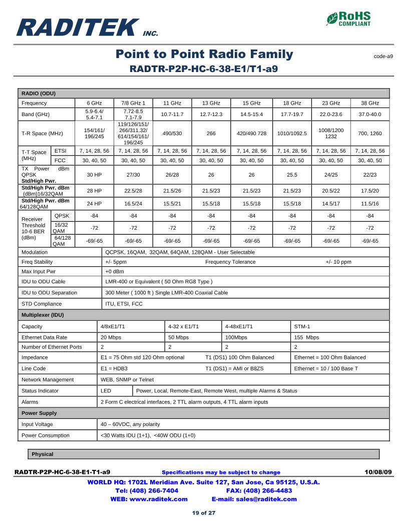
RADIO (ODU)
Frequency 6 GHz 7/8 GHz 1 11 GHz 13 GHz 15 GHz 18 GHz 23 GHz 38 GHz
Band (GHz) 5.9-6.4/ 5.4-7.1
7.72-8.5 7.1-7.9
10.7-11.7 12.7-12.3 14.5-15.4 17.7-19.7 22.0-23.6 37.0-40.0
T-R Space (MHz) 154/161/ 196/245
119/126/151/266/311.32/
614/154/161/ 196/245
490/530 266 420/490 728 1010/1092.5 1008/1200
1232 700, 1260
ETSI 7, 14, 28, 56 7, 14, 28, 56 7, 14, 28, 56 7, 14, 28, 56 7, 14, 28, 56 7, 14, 28, 56 7, 14, 28, 56 7, 14, 28, 56 T-T Space (MHz) FCC 30, 40, 50 30, 40, 50 30, 40, 50 30, 40, 50 30, 40, 50 30, 40, 50 30, 40, 50 30, 40, 50
TX Power dBm QPSK Std/High Pwr.
30 HP 27/30 26/28 26 26 25.5 24/25 22/23
Std/High Pwr. dBm (dBm)16/32QAM
28 HP 22.5/28 21.5/26 21.5/23 21.5/23 21.5/23 20.5/22 17.5/20
Std/High Pwr. dBm 64/128QAM
24 HP 16.5/24 15.5/21 15.5/18 15.5/18 15.5/18 14.5/17 11.5/16
QPSK -84 -84 -84 -84 -84 -84 -84 -84
16/32QAM
-72 -72 -72 -72 -72 -72 -72 -72
Receiver Threshold 10-6 BER (dBm) 64/128
QAM -69/-65 -69/-65 -69/-65 -69/-65 -69/-65 -69/-65 -69/-65 -69/-65
Modulation QCPSK, 16QAM, 32QAM, 64QAM, 128QAM - User Selectable
Freq Stability +/- 5ppm Frequency Tolerance +/- 10 ppm
Max Input Pwr +0 dBm
IDU to ODU Cable LMR-400 or Equivalent ( 50 Ohm RG8 Type )
IDU to ODU Separation 300 Meter ( 1000 ft ) Single LMR-400 Coaxial Cable
STD Compliance ITU, ETSI, FCC
Multiplexer (IDU)
Capacity 4/8xE1/T1 4-32 x E1/T1 4-48xE1/T1 STM-1
Ethernet Data Rate 20 Mbps 50 Mbps 100Mbps 155 Mbps
Number of Ethernet Ports 2 2 2 2
Impedance E1 = 75 Ohm std 120 Ohm optional T1 (DS1) 100 Ohm Balanced Ethernet = 100 Ohm Balanced
Line Code E1 = HDB3 T1 (DS1) = AMI or B8ZS Ethernet = 10 / 100 Base T
Network Management WEB, SNMP or Telnet
Status Indicator LED Power, Local, Remote-East, Remote West, multiple Alarms & Status
Alarms 2 Form C electrical interfaces, 2 TTL alarm outputs, 4 TTL alarm inputs
Power Supply
Input Voltage 40 – 60VDC, any polarity
Power Consumption <30 Watts IDU (1+1), <40W ODU (1+0)
Physical
19 of 27
RADITEK INC.
Point to Point Radio Family code-a9
RADTR-P2P-HC-6-38-E1/T1-a9
RADTR-P2P-HC-6-38-E1-T1-a9 Specifications may be subject to change 10/08/09 WORLD HQ: 1702L Meridian Ave. Suite 127, San Jose, Ca 95125, U.S.A.
Tel: (408) 266-7404 FAX: (408) 266-4483 WEB: www.raditek.com E-mail: [email protected]
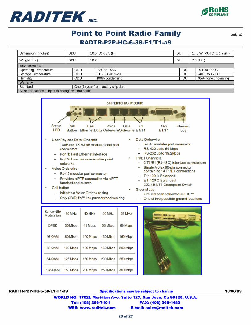
Dimensions (inches) ODU 10.5 (D) x 3.5 (H) IDU 17.5(W) x9.4(D) x 1.75(H)
Weight (lbs.) ODU 10.7 IDU 7.5 (1+1)
Environmental Operating Temperature ODU -33C to +55C IDU -5 C to +55 C Storage Temperature ODU ETS 300-019-2-1 IDU -40 C to +70 C Humidity ODU 100% condensing IDU 95% non-condensing Warranty Standard One (1) year from factory ship date All specifications subject to change without notice
20 of 27
RADTR-4.4-5.0-HC-STM-1-b9 Specifications may be subject to change 03/19/09 WORLD HQ: 1702L Meridian Ave. Suite 127, San Jose, Ca 95125, U.S.A.
Tel: (408) 266-7404 FAX: (408) 266-4483 WEB: www.raditek.com E-mail: [email protected]
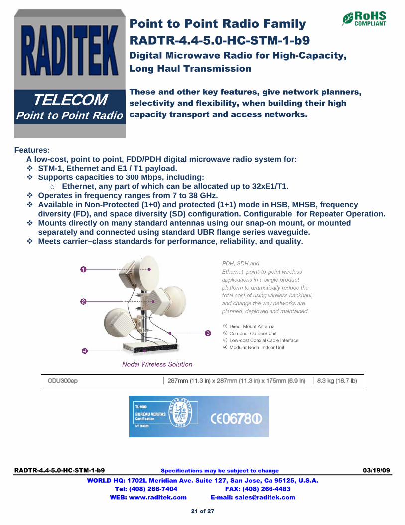
Features:
A low-cost, point to point, FDD/PDH digital microwave radio system for: STM-1, Ethernet and E1 / T1 payload. Supports capacities to 300 Mbps, including:
o Ethernet, any part of which can be allocated up to 32xE1/T1. Operates in frequency ranges from 7 to 38 GHz. Available in Non-Protected (1+0) and protected (1+1) mode in HSB, MHSB, frequency
diversity (FD), and space diversity (SD) configuration. Configurable for Repeater Operation. Mounts directly on many standard antennas using our snap-on mount, or mounted
separately and connected using standard UBR flange series waveguide. Meets carrier–class standards for performance, reliability, and quality.
Point to Point Radio Family RADTR-4.4-5.0-HC-STM-1-b9 Digital Microwave Radio for High-Capacity, Long Haul Transmission These and other key features, give network planners, selectivity and flexibility, when building their high capacity transport and access networks.
TELECOM Point to Point Radio
21 of 27
RADITEK INC.
RADTR-4.4-5.0-HC-STM-1-b9 Specifications may be subject to change 03/19/09 WORLD HQ: 1702L Meridian Ave. Suite 127, San Jose, Ca 95125, U.S.A.
Tel: (408) 266-7404 FAX: (408) 266-4483 WEB: www.raditek.com E-mail: [email protected]
22 of 27

RADFI Point-to-Point Radio 5.7-5.805GHz Specifications may be subject to change 03/19/09 WORLD HQ: 1702L Meridian Ave. Suite 127, San Jose, Ca 95125, U.S.A.
Tel: (408) 266-7404 FAX: (408) 266-4483 WEB: www.raditek.com E-mail: [email protected]
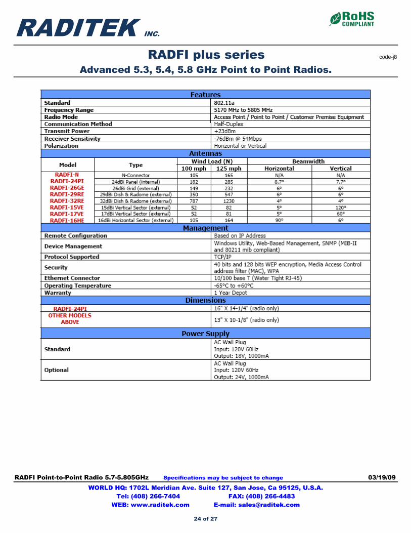
Can be configured as an Access point, Point to Point bridge and CPE
Key Features 23 dBm RF Output Dual Ethernet Ports Tunneling Protocol Support
(VPN, PPTP, RSA, etc.) Wireless Distribution System (WDS) Security (WEP, WPA, MAC Authorization) Status LEDs (in Access Point Mode) Alignment LEDs (in CPE Mode) Client NAT Router with QoS (Quality of Service) SNMP Includes: PoE, Boot-Cover, Mounting Kit (Dual
Ethernet Boot Cover Optional) ODFM Technology Configurable in Point-to-Point, Access Point or
Client Modes WiFi protected Access (WPA): Includes WEP security features Unit has visible LEDs to indicate WEP and WPA activation Visual signal strength for self contained, easy alignment
RADFI plus series Advanced 5.3, 5.4, 5.8 GHz Point to Point Radios.
TELECOM Point to Point Radio
LOW COST
23 of 27
RADITEK INC.
RADFI plus series code-j8
Advanced 5.3, 5.4, 5.8 GHz Point to Point Radios.
RADFI Point-to-Point Radio 5.7-5.805GHz Specifications may be subject to change 03/19/09 WORLD HQ: 1702L Meridian Ave. Suite 127, San Jose, Ca 95125, U.S.A.
Tel: (408) 266-7404 FAX: (408) 266-4483 WEB: www.raditek.com E-mail: [email protected]
24 of 27
RM500 Mesh Router Specifications may be subject to change 02/11/09 WORLD HQ: 1702L Meridian Ave. Suite 127, San Jose, Ca 95125, U.S.A.
Tel: (408) 266-7404 FAX: (408) 266-4483 WEB: www.raditek.com E-mail: [email protected]
WiFi
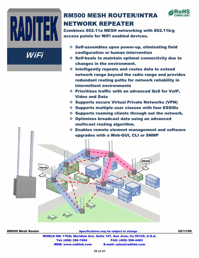
RM500 MESH ROUTER/INTRA NETWORK REPEATER Combines 802.11a MESH networking with 802.11b/g access points for WiFi enabled devices. Self-assembles upon power-up, eliminating field
configuration or human intervention Self-heals to maintain optimal connectivity due to
changes in the environment. Intelligently repeats and routes data to extend
network range beyond the radio range and provides redundant routing paths for network reliability in intermittent environments
Prioritizes traffic with an advanced QoS for VoIP, Video and Data
Supports secure Virtual Private Networks (VPN) Supports multiple user classes with four ESSIDs Supports roaming clients through out the network. Optimizes broadcast data using an advanced
multicast routing algorithm. Enables remote element management and software
upgrades with a Web-GUI, CLI or SNMP
25 of 27
RADITEK for WiMAX Brochure Specifications may be subject to change 03/19/09 WORLD HQ: 1702L Meridian Ave. Suite 127, San Jose, Ca 95125, U.S.A. Tel: (408) 266-7404 FAX: (408) 266-4483 WEB: www.raditek.com E-mail: [email protected]
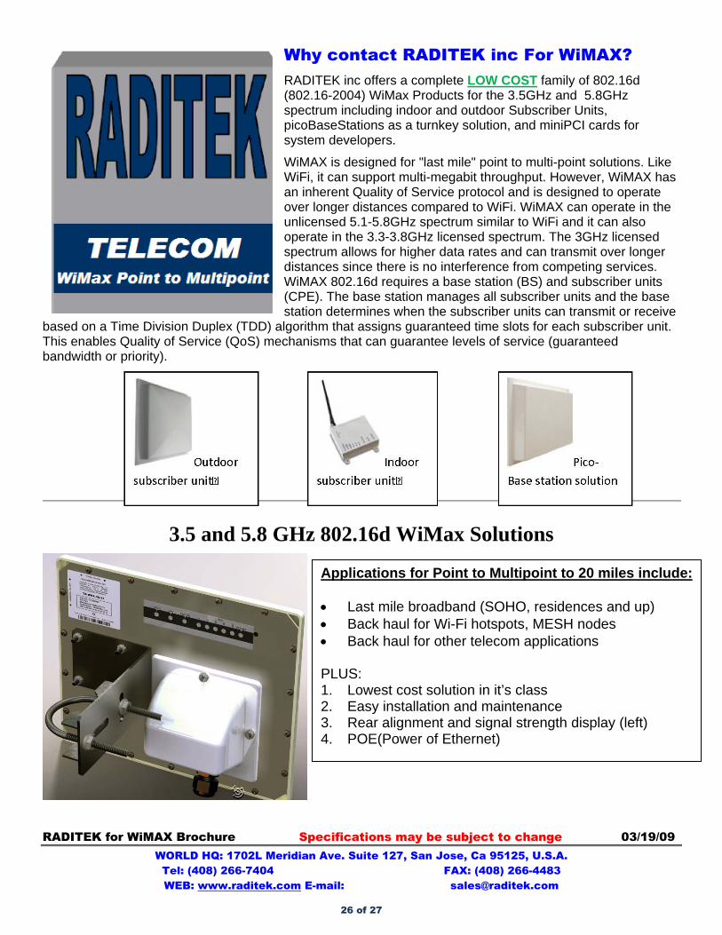
Why contact RADITEK inc For WiMAX? RADITEK inc offers a complete LOW COST family of 802.16d (802.16-2004) WiMax Products for the 3.5GHz and 5.8GHz spectrum including indoor and outdoor Subscriber Units, picoBaseStations as a turnkey solution, and miniPCI cards for system developers.
WiMAX is designed for "last mile" point to multi-point solutions. Like WiFi, it can support multi-megabit throughput. However, WiMAX has an inherent Quality of Service protocol and is designed to operate over longer distances compared to WiFi. WiMAX can operate in the unlicensed 5.1-5.8GHz spectrum similar to WiFi and it can also operate in the 3.3-3.8GHz licensed spectrum. The 3GHz licensed spectrum allows for higher data rates and can transmit over longer distances since there is no interference from competing services. WiMAX 802.16d requires a base station (BS) and subscriber units (CPE). The base station manages all subscriber units and the base station determines when the subscriber units can transmit or receive
based on a Time Division Duplex (TDD) algorithm that assigns guaranteed time slots for each subscriber unit. This enables Quality of Service (QoS) mechanisms that can guarantee levels of service (guaranteed bandwidth or priority).
3.5 and 5.8 GHz 802.16d WiMax Solutions
Applications for Point to Multipoint to 20 miles include:
• Last mile broadband (SOHO, residences and up) • Back haul for Wi-Fi hotspots, MESH nodes • Back haul for other telecom applications PLUS: 1. Lowest cost solution in it’s class 2. Easy installation and maintenance 3. Rear alignment and signal strength display (left) 4. POE(Power of Ethernet)
26 of 27
RADITEK for WiMAX Brochure Specifications may be subject to change 03/19/09 WORLD HQ: 1702L Meridian Ave. Suite 127, San Jose, Ca 95125, U.S.A. Tel: (408) 266-7404 FAX: (408) 266-4483 WEB: www.raditek.com E-mail: [email protected]
RADITEK INC.
SPECIFICATIONS
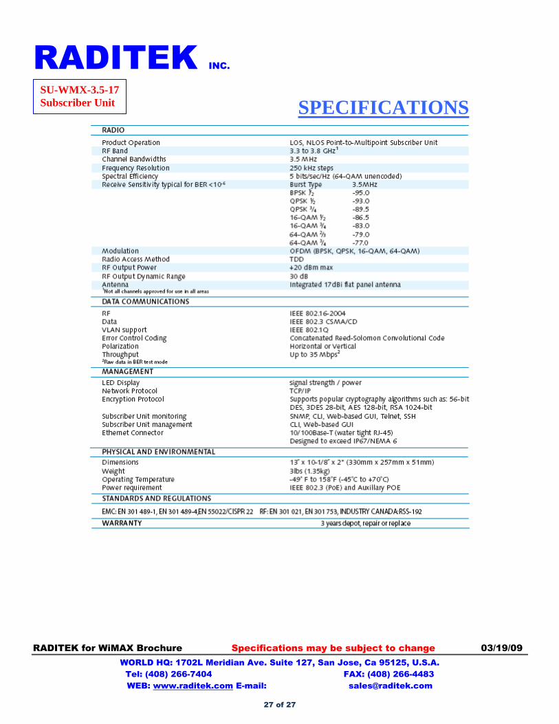
SU-WMX-3.5-17 Subscriber Unit
27 of 27