Embed Size (px)
Citation preview
Contact: Yuji Tochio
Fujitsu
Japan
Tel: +81-44-754-8829
Email: [email protected]
Attention: This is not a publication made available to the public, but an internal ITU-T Document intended only for use by the
Member States of ITU, by ITU-T Sector Members and Associates, and their respective staff and collaborators in their ITU related work.
It shall not be made available to, and used by, any other persons or entities without the prior written consent of ITU-T.
INTERNATIONAL TELECOMMUNICATION UNION STUDY GROUP 15
TELECOMMUNICATION
STANDARDIZATION SECTOR
STUDY PERIOD 2013-2016
TD 467 (PLEN/15)
English only
Original: English
Question(s): 10, 14/15 15-26 February 2016
TD
Source: Editor G.8121.1/Y.1381.1
Title: Draft revised Recommendation ITU-T G.8121.1/Y.1381.1 (for Consent, 26 February
2016)
Abstract
This document provides the draft revised G.8121.1/Y.1381.1 (for consent, 26 February 2016).
Summary of major updates from version 1 (G.8121.1 (2013))
- To support proactive LM and DM in align with draft G.8113.1 (wd20, Ottawa), clause 9.2.1
defines MIs for proactive LM and DM. Also the placeholders of 8.8.4 and 8.8.6 are provided.
- Added intermediate request to on-demand loss/delay measurement in clause 8.8.5/7 and clause
9.4.1.1 (MTDe_TT)
- Fixed some behaviors in OAM related processes in clause 8.8.
- Fixed LStack bahaviour in some atomic functions in clause 9
- Fixed some incorrect titles of references.
- Fixed some incorrect diagrams (including SDL diagrams)

- 1 -
TD 467 (PLEN/15)
Draft revised Recommendation ITU-T G.8121.1/Y.1381.1
Characteristics of MPLS-TP equipment functional blocks supporting
ITU-T G.8113.1/Y.13731372.1 OAM mechanisms
Summary
Recommendation ITU-T G.8121.1/Y.1381.1 specifies both the functional components and the
methodology that should be used in order to specify MPLS-TP layer network functionality of
network elements based on the protocol neutral constructs defined in ITU-T G.8121 and on the
tools defined in ITU-T G.8113.1/Y.13723.1.
Keywords
Atomic functions, equipment functional blocks, MPLS-TP layer network, MPLS-TP.
- 2 -
TD 467 (PLEN/15)
Draft revised Recommendation ITU-T G.8121.1/Y.1381.1
Characteristics of MPLS-TP equipment functional blocks supporting
ITU-T G.8113.1/Y.13731372.1 OAM mechanisms
1 Scope
This Recommendation describes both the functional components and the methodology that should
be used in order to describe MPLS-TP layer network functionality of network elements; it does not
describe individual MPLS-TP network equipment as such.
This recommendation provides protocol-specific extensions of the protocol-neutral constructs
defined in [ITU-T G.8121] to support the OAM tools defined in [ITU-T G.8113.1]
This Recommendation provides a description of the MPLS-TP functional technology using the
same methodologies that have been used for other transport technologies (e.g. SDH, OTN and
Ethernet).
This Recommendation forms part of a suite of Recommendations covering the full functionality of
network equipment. These Recommendations are [ITU-T G.806], [ITU-T G.8121], [ITU-T G.798],
[ITU-T G.783], [ITU-T G.705] and [ITU-T G.8021]. This Recommendation also follows the
principles defined in [ITU-T G.805].
These Recommendations specify a library of basic building blocks and a set of rules by which they
may be combined in order to describe digital transmission equipment. The library comprises the
functional building blocks needed to specify completely the generic functional structure of the
MPLS-TP layer network. In order to be compliant with this Recommendation, equipment needs to
be describable as an interconnection of a subset of these functional blocks contained within this
Recommendation. The interconnections of these blocks should obey the combination rules given.
Not every atomic function defined in this Recommendation is required for every application.
Different subsets of atomic functions may be assembled in different ways according to the
combination rules given in this Recommendation to provide a variety of different capabilities.
Network operators and equipment suppliers may choose which functions must be implemented for
each application.
2 References
The following ITU-T Recommendations and other references contain provisions, which, through
reference in this text, constitute provisions of this Recommendation. At the time of publication, the
editions indicated were valid. All Recommendations and other references are subject to revision;
users of this Recommendation are therefore encouraged to investigate the possibility of applying the
most recent edition of the Recommendations and other references listed below. A list of the
currently valid ITU-T Recommendations is regularly published.
The reference to a document within this Recommendation does not give it, as a stand-alone
document, the status of a Recommendation.
[ITU-T G.705] Recommendation ITU-T G.705 (2000), Characteristics of plesiochronous
digital hierarchy (PDH) equipment functional blocks.
[ITU-T G.783] Recommendation ITU-T G.783 (2006), Characteristics of synchronous digital
hierarchy (SDH) equipment functional blocks.

- 3 -
TD 467 (PLEN/15)
[ITU-T G.798] Recommendation ITU-T G.798 (2010), Characteristics of optical transport
network hierarchy equipment functional blocks
[ITU-T G.805] Recommendation ITU-T G.805 (2000), Generic functional architecture of
transport networks.
[ITU-T G.806] Recommendation ITU-T G.806 (2012), Characteristics of transport equipment
– Description methodology and generic functionality.
[ITU-T G.8021] Recommendation ITU-T G.8021/Y.1341 (2015), Characteristics of Ethernet
transport network equipment functional blocks.
[ITU-T G.8101] Recommendation ITU-T G.8101/Y.1355 (2015), Terms and definitions for
MPLS transport profile.
[ITU-T G.8113.1] Recommendation ITU-T G.8113.1/Y.1372.1 (2013), Operations,
administration and maintenance mechanism for MPLS-TP in packet transport
networks
[ITU-T G.8121] Recommendation ITU-T G.8121/Y.1381 (20152013), Characteristics of
MPLS-TP equipment functional blocks
[ITU-T G.8113.1] Recommendation ITU-T G.8113.1/Y.1371.1 (2015), Operations,
administration and maintenance mechanism for MPLS-TP in packet transport
networks
3 Definitions
3.1 Terms defined elsewhere:
This Recommendation uses the following terms defined elsewhere:
3.1.1 access point : [ITU-T G.805]
3.1.2 adapted information: [ITU-T G.805]
3.1.3 characteristic information: [ITU-T G.805]
3.1.4 client/server relationship: [ITU-T G.805]
3.1.5 connection: [ITU-T G.805]
3.1.6 connection point: [ITU-T G.805]
3.1.7 layer network: [ITU-T G.805]
3.1.8 network : [ITU-T G.805]
3.1.9 network connection: [ITU-T G.805]
3.1.10 reference point: [ITU-T G.805]
3.1.11 subnetwork: [ITU-T G.805]
3.1.12 subnetwork connection: [ITU-T G.805]
3.1.13 termination connection point: [ITU-T G.805]
3.1.14 trail: [ITU-T G.805]
3.1.15 trail termination: [ITU-T G.805]
3.1.16 transport: [ITU-T G.805]
- 4 -
TD 467 (PLEN/15)
3.1.17 transport entity: [ITU-T G.805]
3.1.18 label: [ITU-T G.8101]
3.1.19 label stack: [ITU-T G.8101]
3.1.20 MPLS label stack: [ITU-T G.8101]
3.1.21 label switched path: [ITU-T G.8101]
3.1.22 Bottom of Stack: [ITU-T G.8101]
3.1.23 Time To Live: [ITU-T G.8101]
3.1.24 Label value: [ITU-T G.8101]
3.1.25 Per-Hop Behaviour: [ITU-T G.8101]
3.1.26 Associated Channel Header: [ITU-T G.8101]
3.1.27 Generic Associated Channel: [ITU-T G.8101]
3.1.28 G-ACh Label: [ITU-T G.8101]
3.1.29 traffic class: [ITU-T G.8101]
3.2 Terms defined in this Recommendation
This Recommendation defines the following terms:
None
4 Abbreviations and acronyms
This Recommendation uses the following abbreviations and acronyms:
ACH Associated Channel Header
AI Adapted Information
AIS Alarm indication signal
AP Access Point
APS Automatic protection switching
CC Continuity Check
CC/CV Continuity Check and Connectivity Verification
CCM Continuity Check Message
CI Characteristic Information
CoS Class of Service
CP Connection Point
CSF Client Signal Fail
CV Connectivity Verification
CW Control Word
DM Delay Measurement
DP Drop Precedence
DT Diagnostic Test
EMF Equipment Management Function
FP Flow Point
FTP Flow termination point
G-ACh Generic Associated Channel
GAL G-ACh Label
GFP-F Frame-mapped Generic Framing Procedure
LCK Locked
- 5 -
TD 467 (PLEN/15)
LM Loss Measurement
LOS Loss of Signal
LStack Label Stack
MCC Maintenance Communication Channel
MEG Maintenance Entity Group (New)
MEP Maintenance entity group (MEG) End Point
MIP Maintenance entity group (MEG) Intermediate Point
MP Management Point
MPLS Multi-Protocol Label Switching
MPLS-TP Multi-Protocol Label Switching - Transport Profile
MT Multi-Protocol Label Switching - Transport Profile
MTDe MPLS-TP MEP Diagnostic function
MTDi MPLS-TP MIP Diagnostic function
OAM Operation, Administration and Maintenance
PDU Protocol Data Unit
PHB Per Hop Behaviour
PW Pseudowire
PSC PHB Scheduling Class
RDI Remote Detect Indidation
RI Remote Information
RP Remote Point
RT Route Trace
SCC Signalling Communication Channel
TCP Termination Connection Point
TFP Termination Flow Point
TH Throughput
TTL Time-To-Live
PM Performance Monitoring
SSF Server Signal Fail
TC Traffic Class
TLV Type Length Value
TSD Trail Signal Degrade
TSF Trail Signal Fail
5 Conventions
The diagrammatic convention for connection-oriented layer networks described in this
Recommendation is that of [ITU T G.805].
In this Recommendation, MI_LMC_Enable and MI_LML_Enable are used to mean
MI_1LMp_Enable and MI_LMp_Enable as described in [ITU-T G.8121].
6 Supervision
The generic supervision functions are defined in clause 6 in [ITU-T G.806]. Protocol neutral
supervision functions for the MPLS-TP network are defined in this clause 6 in [ITU-T G.8121].
Specific supervision functions for the MPLS-TP network are defined in this clause.

- 6 -
TD 467 (PLEN/15)
6.1 Defects
The defect Entry and Exit conditions are based on events. Occurrence or absence of specific events
may raise or reset specific defects.
The events used by this recommendation are defined in Table 6-1 in [ITU-T G.8121].
6.2 Consequent actions
For generic consequent actions, see [ITU-T G.806]. For the specific consequent actions applicable
to MPLS-TP, refer the specific atomic functions.
6.3 Defect correlations
For the defect correlations, see the specific atomic functions.
6.4 Performance filters
For further study
7 Information flow across reference points
Information flow for MPLS-TP functions is defined in clause 9. A generic description of
information flow is defined in clause 7 in [ITU-T G.806].
8 MPLS-TP processes
8.1 G-ACh Process
See the clause 8.1in [ITU-T G.8121]
8.2 TC/Label processes
See the clause 8.2 in [ITU-T G.8121]
8.3 Queuing process
See the clause 8.3 in [ITU-T G.8121]
8.4 MPLS-TP-specific GFP-F processes
See the clause 8.4 in [ITU-T G.8121]
8.5 Control Word (CW) processes
See the clause 8.5 in [ITU-T G.8121]
8.6 OAM related Processes used by Server adaptation functions
8.6.1 Selector Process
See the clause 8.6.1[ITU-T G.8121]
- 7 -
TD 467 (PLEN/15)
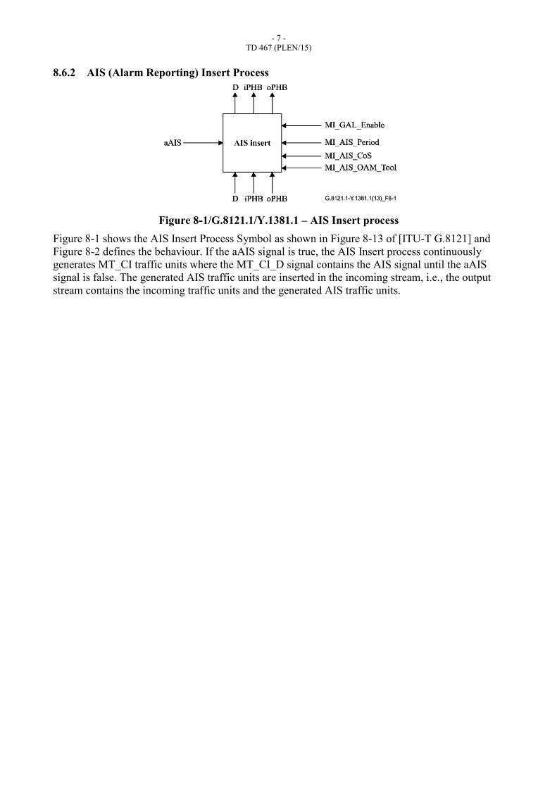
8.6.2 AIS (Alarm Reporting) Insert Process
Figure 8-1/G.8121.1/Y.1381.1 – AIS Insert process
Figure 8-1 shows the AIS Insert Process Symbol as shown in Figure 8-13 of [ITU-T G.8121] and
Figure 8-2 defines the behaviour. If the aAIS signal is true, the AIS Insert process continuously
generates MT_CI traffic units where the MT_CI_D signal contains the AIS signal until the aAIS
signal is false. The generated AIS traffic units are inserted in the incoming stream, i.e., the output
stream contains the incoming traffic units and the generated AIS traffic units.
- 8 -
TD 467 (PLEN/15)
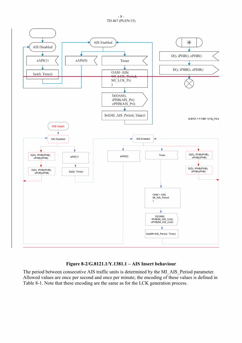
Figure 8-2/G.8121.1/Y.1381.1 – AIS Insert behaviour
The period between consecutive AIS traffic units is determined by the MI_AIS_Period parameter.
Allowed values are once per second and once per minute; the encoding of these values is defined in
Table 8-1. Note that these encoding are the same as for the LCK generation process.
aAIS(1)Timer
Set(0, Timer)
Set(MI=AIS_Period, Timer)
AIS EnabledAIS Disabled
AIS insert
OAM = AIS(
MI_AIS_Period
)
D(D), iPHB(iPHB),
oPHB(oPHB)
D(D), iPHB(iPHB),
oPHB(oPHB)aAIS(0)
D(D), iPHB(iPHB),
oPHB(oPHB)
D(D), iPHB(iPHB),
oPHB(oPHB)
D(OAM),iPHB(MI_AIS_CoS),oPHB(MI_AIS_CoS)
- 9 -
TD 467 (PLEN/15)
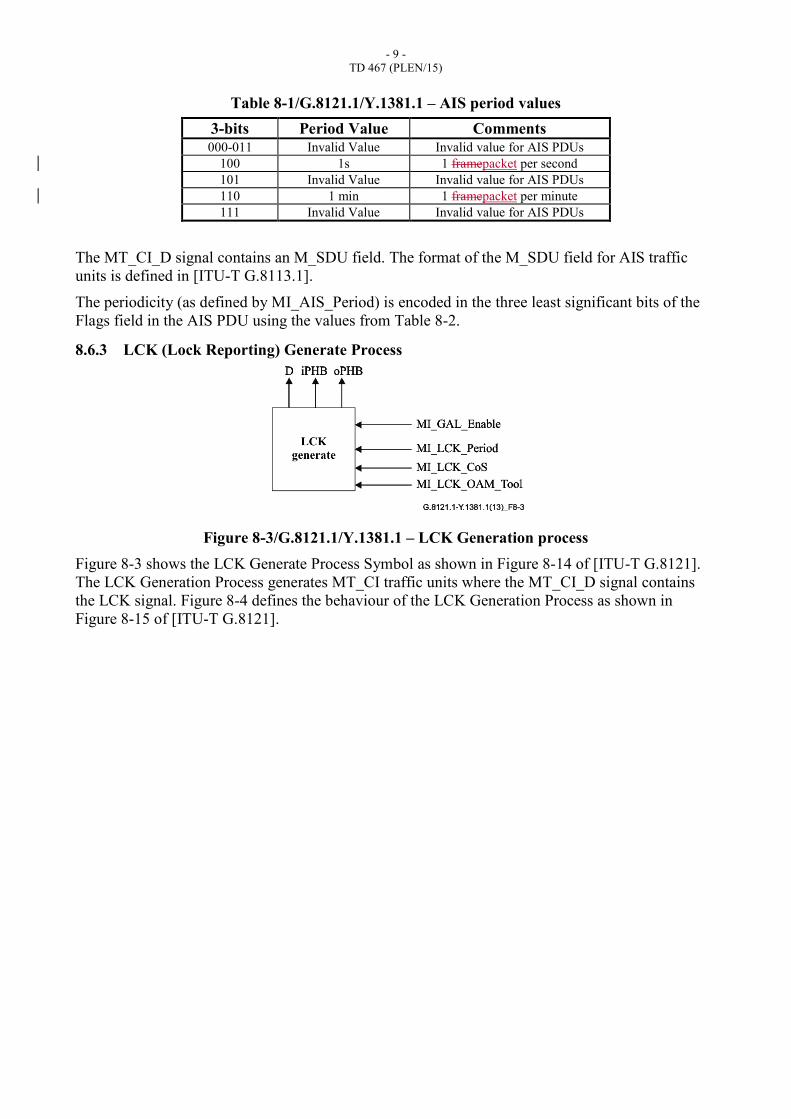
Table 8-1/G.8121.1/Y.1381.1 – AIS period values
3-bits Period Value Comments 000-011 Invalid Value Invalid value for AIS PDUs
100 1s 1 framepacket per second 101 Invalid Value Invalid value for AIS PDUs 110 1 min 1 framepacket per minute 111 Invalid Value Invalid value for AIS PDUs
The MT_CI_D signal contains an M_SDU field. The format of the M_SDU field for AIS traffic
units is defined in [ITU-T G.8113.1].
The periodicity (as defined by MI_AIS_Period) is encoded in the three least significant bits of the
Flags field in the AIS PDU using the values from Table 8-2.
8.6.3 LCK (Lock Reporting) Generate Process
Figure 8-3/G.8121.1/Y.1381.1 – LCK Generation process
Figure 8-3 shows the LCK Generate Process Symbol as shown in Figure 8-14 of [ITU-T G.8121].
The LCK Generation Process generates MT_CI traffic units where the MT_CI_D signal contains
the LCK signal. Figure 8-4 defines the behaviour of the LCK Generation Process as shown in
Figure 8-15 of [ITU-T G.8121].
- 10 -
TD 467 (PLEN/15)
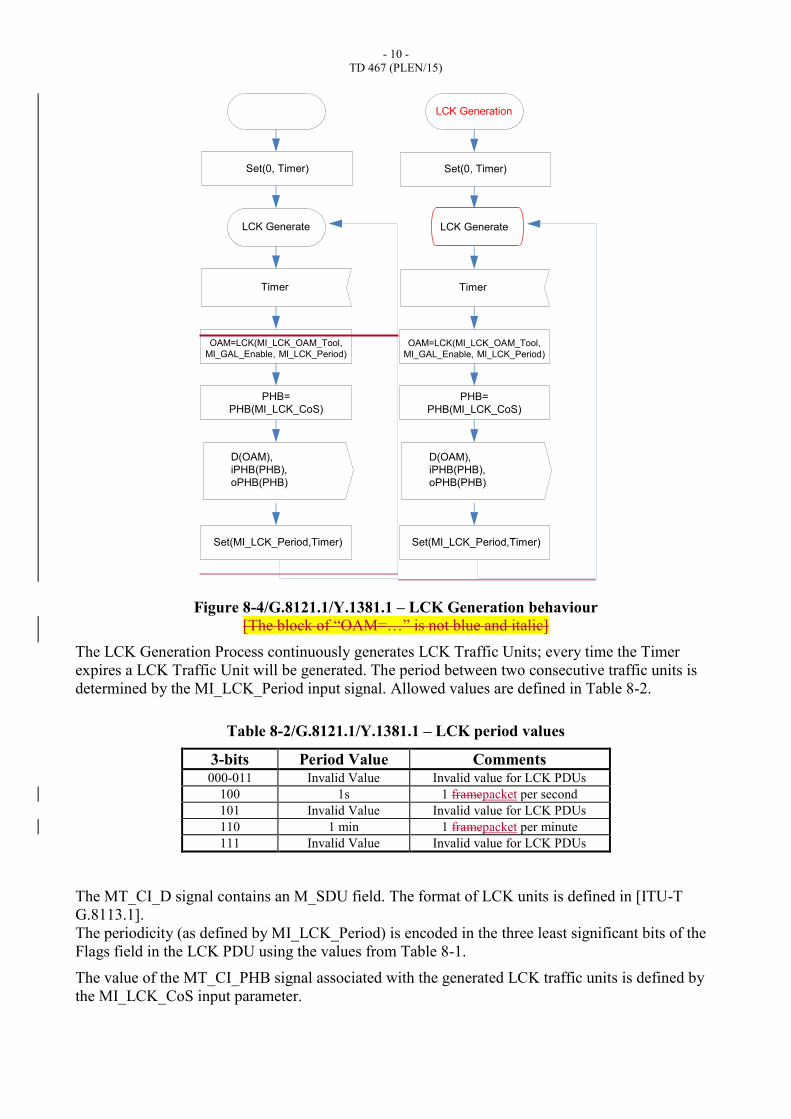
Figure 8-4/G.8121.1/Y.1381.1 – LCK Generation behaviour
[The block of “OAM=…” is not blue and italic]
The LCK Generation Process continuously generates LCK Traffic Units; every time the Timer
expires a LCK Traffic Unit will be generated. The period between two consecutive traffic units is
determined by the MI_LCK_Period input signal. Allowed values are defined in Table 8-2.
Table 8-2/G.8121.1/Y.1381.1 – LCK period values
3-bits Period Value Comments 000-011 Invalid Value Invalid value for LCK PDUs
100 1s 1 framepacket per second 101 Invalid Value Invalid value for LCK PDUs 110 1 min 1 framepacket per minute 111 Invalid Value Invalid value for LCK PDUs
The MT_CI_D signal contains an M_SDU field. The format of LCK units is defined in [ITU-T
G.8113.1].
The periodicity (as defined by MI_LCK_Period) is encoded in the three least significant bits of the
Flags field in the LCK PDU using the values from Table 8-1.
The value of the MT_CI_PHB signal associated with the generated LCK traffic units is defined by
the MI_LCK_CoS input parameter.
Timer
LCK Generate
Set(0, Timer)
OAM=LCK(MI_LCK_OAM_Tool,
MI_GAL_Enable, MI_LCK_Period)
D(OAM),
iPHB(PHB),
oPHB(PHB)
Set(MI_LCK_Period,Timer)
PHB=
PHB(MI_LCK_CoS)
Timer
LCK Generate
Set(0, Timer)
OAM=LCK(MI_LCK_OAM_Tool,
MI_GAL_Enable, MI_LCK_Period)
D(OAM),
iPHB(PHB),
oPHB(PHB)
Set(MI_LCK_Period,Timer)
PHB=
PHB(MI_LCK_CoS)
LCK Generation
- 11 -
TD 467 (PLEN/15)
8.7 OAM related Processes used by adaptation functions
8.7.1 MCC/SCC Mapping Insert and De-mapping Process
See the clause 8.7.1in [ITU-T G.8121]
8.7.2 APS Insert and ExtractProcess
See the clause 8.7.2 in [ITU-T G.8121]
8.7.3 CSF Insert and Extract Process
See the clause 8.7.3 in [ITU-T G.8121]
8.8 Pro-active and on-demand OAM related Processes
8.8.1 Proactive Continuity Check and Connectivity Verification (CC/CV)
8.8.1.1 Overview
To support CC/CV, the Continuity Check Message (CCM) as described in [ITU-T G.8113.1] clause
8.2.1 is used.

- 12 -
TD 467 (PLEN/15)
Co
un
ter
G-ACh
Insertion
OAM PDU
Generation
CCM
Source
Control
MI_CC_OAM_Tool
MI_RDI_OAM_Tool
MI_CC_EnableMI_LMC_Enable
MI_MEG_ID
MI_MEP_IDMI_CC_Period
MI_CC_CoS
MI_GAL_Enable
MI_TTLVALUE
CCM
Sink
Control
OAM PDU
Reception
G-ACh
Extraction
MI_CC_OAM_Tool
MI_RDI_OAM_Tool
MI_LMC_EnableMI_MEG_ID
MI_PeerMEP_ID
MI_CC_PeriodMI_Get_SvdCC
MI_SvdCC
RI_CC_RxFCl
RI_CC_TxFCf
RI_CC_RDI
RxFCl
TxFCf
RxFCb
TxFCb
LMC
Sink
Control
MI_GAL_Enable
Co
un
ter
MT_CI
MT_CI
G-ACh
Extraction
OAM PDU
Reception
CCM
Sink
Control
CCM
Sink
Control
OAM PDU
Generation
G-ACh
Extraction
MT_CI
Co
un
ter
Co
un
ter
MI_GAL_Enable
MI_TTLVALUE
LMC
Sink
Control
MI_GAL_Enable
MI_SvdCC
MI_CC_CoS
RI_CC_RDI
RI_CC_RxFCl
RI_CC_TxFCf
RxFCl
TxFCf
RxFCb
TxFCb
On-demand
MIP
On-demand
MIP
TxFCl
RxFCl
MI_CC_CoS
MI_CC_CoS
RxFCl
MT_CI
MI_CC_OAM_Tool
MI_RDI_OAM_Tool
MI_CC_EnableMI_LMC_Enable
MI_MEG_ID
MI_MEP_IDMI_CC_Period
MI_CC_OAM_Tool
MI_RDI_OAM_Tool
MI_LMC_EnableMI_MEG_ID
MI_PeerMEP_ID
MI_CC_PeriodMI_Get_SvdCC
Figure 8-5/G.8121.1/Y.1381.1 – Overview of Processes involved with CCM
Figure 8-5 provides an overview of the processes that support the CC/CV function by using CCM.
The CCM Generation process generates the CCM framepackets if MI_CC_Enable is true. The
- 13 -
TD 467 (PLEN/15)
MI_MEG_ID and MI_MEP_ID are the MEG and MEP IDs of the MEP itself and these IDs are
carried in the CCM framepacket. The CCM framepackets are generated with a periodicity
determined by MI_CC_Period and with a priority determined by MI_CC_CoS. If MI_LMC_Enable
is set, the CCM framepackets will also carry Loss Measurement information. The Generated CCM
Traffic Units are inserted in the flow of MT_CI by the OAM MEP Source Insertion Process.
MI_MEP_ID contains an integer value in the range 1-8191.
The CCM framepackets pass transparently through MIPs.
The OAM MEP Sink Extraction process extracts the CCM Unit from the flow of MT_CI and the
CCM Reception process processes the received CCM Traffic Unit. It compares the received MEG
ID with the provisioned MI_MEG_ID, and the received MEP_ID with the provisioned
MI_PeerMEP_ID; this contains the list of all expected peer MEPs in the MEG. Based on the
processing of this framepacket one or more events may be generated that serve as input for the
Defect Detection Process (not shown in Figure 8-5).
RDI information is carried in the CCM framepacket based upon the RI_CC_RDI input. It is
extracted in the CCM Reception Process.
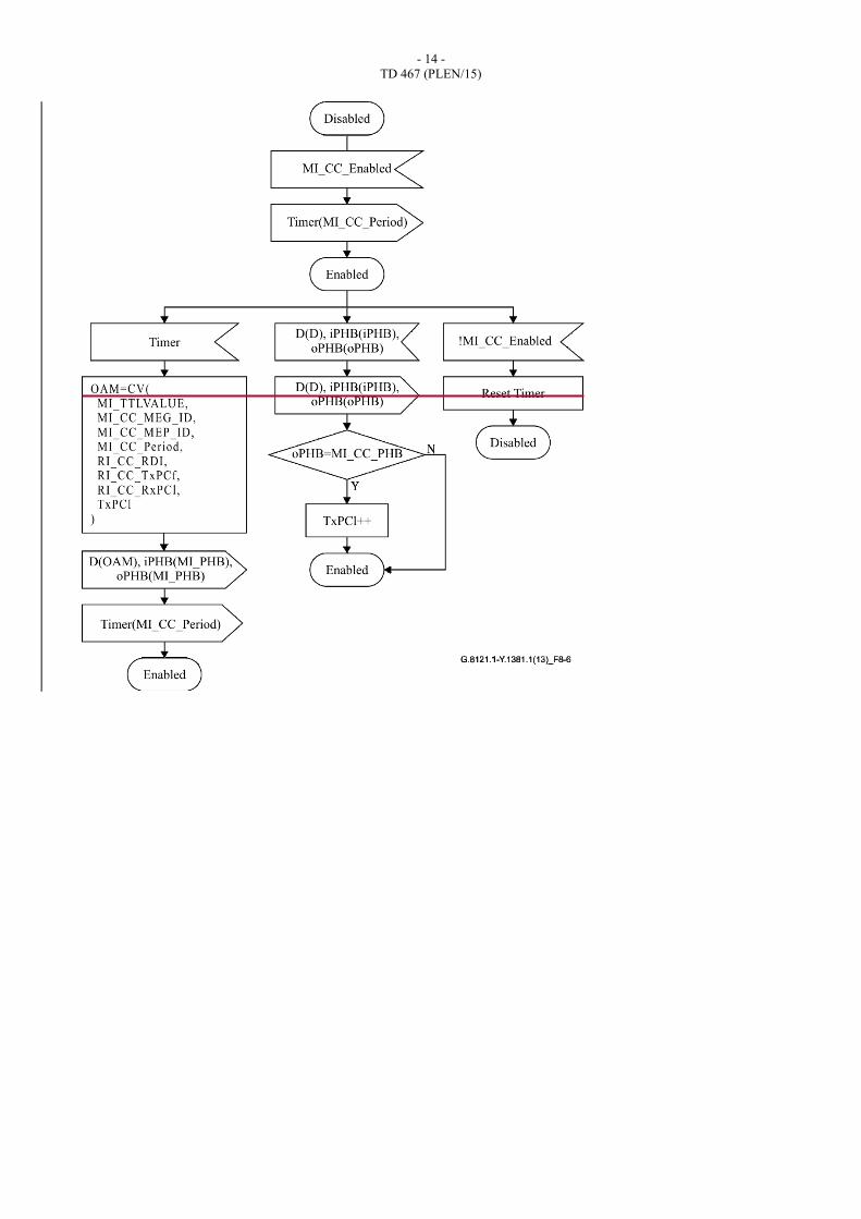
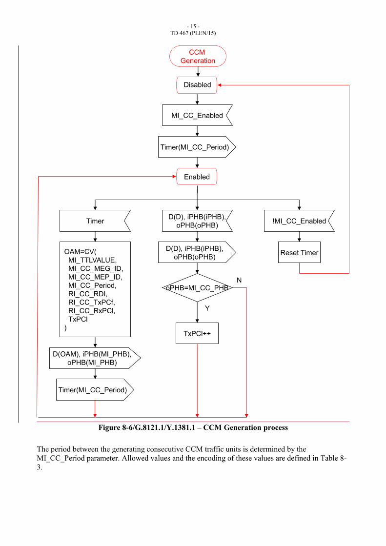
8.8.1.2 CCM Generation Process
Figure 8-6 describes the behaviour for the CCM Generation Process.
This process generates MPLS-TP CI traffic units where MT_CI_D signal contains the CCM traffic
units for pro-active monitoring and counts all data framepackets with PHB equal to MI_CC_CoS
(TxPCl).
The D, iPHB and oPHB signal are forwarded unchanged as indicated by in Figure 8-6
The CCM Generation process can be enabled and disabled using the MI_CC_Enable signal.
- 14 -
TD 467 (PLEN/15)
- 15 -
TD 467 (PLEN/15)
Figure 8-6/G.8121.1/Y.1381.1 – CCM Generation process
The period between the generating consecutive CCM traffic units is determined by the
MI_CC_Period parameter. Allowed values and the encoding of these values are defined in Table 8-
3.
MI_CC_Enabled
Timer(MI_CC_Period)
OAM=CV(
MI_TTLVALUE,
MI_CC_MEG_ID,
MI_CC_MEP_ID,
MI_CC_Period,
RI_CC_RDI,
RI_CC_TxPCf,
RI_CC_RxPCl,
TxPCl
)
D(OAM), iPHB(MI_PHB),
oPHB(MI_PHB)
Timer
Timer(MI_CC_Period)
D(D), iPHB(iPHB),
oPHB(oPHB)
D(D), iPHB(iPHB),
oPHB(oPHB)
oPHB=MI_CC_PHB
Y
TxPCl++
N
!MI_CC_Enabled
Reset Timer
Disabled
CCM
Generation
Enabled
- 16 -
TD 467 (PLEN/15)
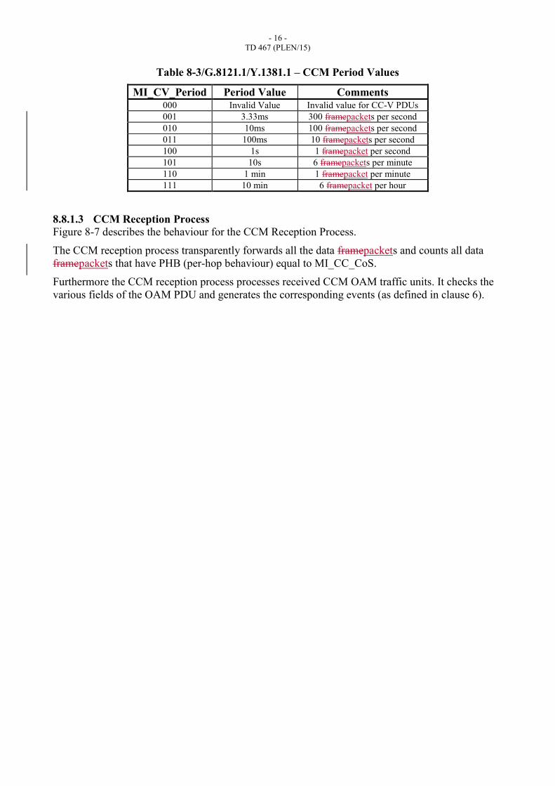
Table 8-3/G.8121.1/Y.1381.1 – CCM Period Values
MI_CV_Period Period Value Comments 000 Invalid Value Invalid value for CC-V PDUs 001 3.33ms 300 framepackets per second 010 10ms 100 framepackets per second 011 100ms 10 framepackets per second 100 1s 1 framepacket per second 101 10s 6 framepackets per minute 110 1 min 1 framepacket per minute 111 10 min 6 framepacket per hour
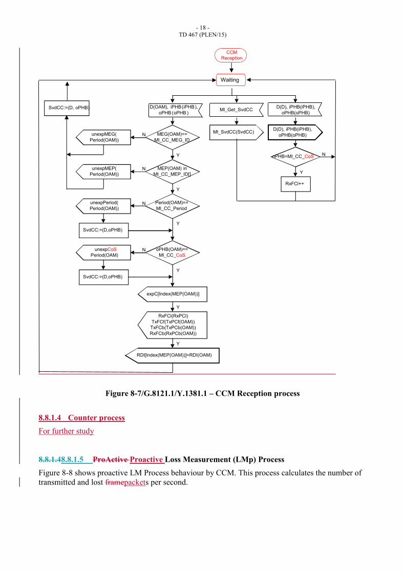
8.8.1.3 CCM Reception Process
Figure 8-7 describes the behaviour for the CCM Reception Process.
The CCM reception process transparently forwards all the data framepackets and counts all data
framepackets that have PHB (per-hop behaviour) equal to MI_CC_CoS.
Furthermore the CCM reception process processes received CCM OAM traffic units. It checks the
various fields of the OAM PDU and generates the corresponding events (as defined in clause 6).

- 17 -
TD 467 (PLEN/15)
- 18 -
TD 467 (PLEN/15)
Figure 8-7/G.8121.1/Y.1381.1 – CCM Reception process
8.8.1.4 Counter process
For further study
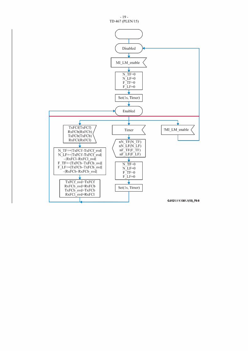
8.8.1.48.8.1.5 ProActive Proactive Loss Measurement (LMp) Process
Figure 8-8 shows proactive LM Process behaviour by CCM. This process calculates the number of
transmitted and lost framepackets per second.
CCM
Reception
D(OAM), iPHB(iPHB),
oPHB (oPHB )
MEG(OAM)==
MI_CC_MEG_ID
Y
MEP(OAM) in
MI_CC_MEP_ID[]
Y
Period(OAM)==
MI_CC_Period
Y
oPHB(OAM)==
MI_CC_CoS
Y
NunexpMEG(
Period(OAM))
NunexpMEP(
Period(OAM))
N
expC[Index(MEP(OAM))]
SvdCC:=(D,oPHB)
NunexpCoS
Period(OAM)
SvdCC:=(D,oPHB)
unexpPeriod(
Period(OAM))
Y
RDI[Index(MEP(OAM))]=RDI(OAM)
SvdCC:=(D, oPHB) MI_Get_SvdCC
MI_SvdCC(SvdCC)
D(D), iPHB(iPHB),
oPHB(oPHB)
D(D), iPHB(iPHB),
oPHB(oPHB)
oPHB=MI_CC_CoS
Y
N
RxFCl++
RxFCl(RxPCl)
TxFCf(TxPCf(OAM))
TxFCb(TxPCb(OAM))
RxFCb(RxPCb(OAM))
Y
Waiting
- 19 -
TD 467 (PLEN/15)
- 20 -
TD 467 (PLEN/15)
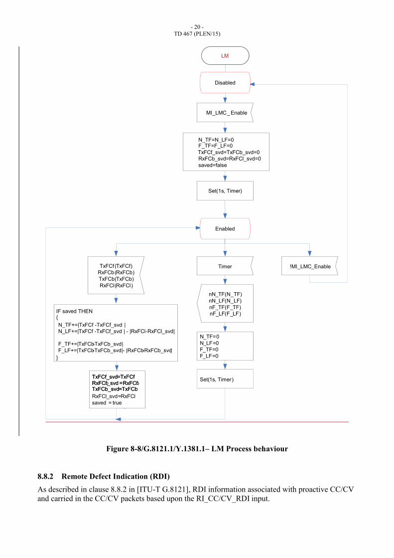
Figure 8-8/G.8121.1/Y.1381.1– LM Process behaviour
8.8.2 Remote Defect Indication (RDI)
As described in clause 8.8.2 in [ITU-T G.8121], RDI information associated with proactive CC/CV
and carried in the CC/CV packets based upon the RI_CC/CV_RDI input.
Timer
nN_TF(N_TF)
nN_LF(N_LF)
nF_TF(F_TF)
nF_LF(F_LF)
N_TF=0
N_LF=0
F_TF=0
F_LF=0
MI_LMC_ Enable
!MI_LMC_Enable
Set(1s, Timer)
Set(1s, Timer)
TxFCf (TxFCf)
RxFCb(RxFCb)
TxFCb(TxFCb)
RxFCl(RxFCl)
N_TF=N_LF=0F_TF=F_LF=0
TxFCf_svd=TxFCb_svd=0
RxFCb_svd=RxFCl_svd=0
saved=false
IF saved THEN{
}
TxFCb_svd=TxFCbTxFCb_svd=TxFCb
TxFCf_svd=TxFCf
RxFCf_svd =RxFCf
TxFCf_svd=TxFCf
RxFCb_svd =RxFCb
RxFCl_svd=RxFCl
saved = true
N_TF+=|TxFCf -TxFCf_svd |
N_LF+=|TxFCf -TxFCf_svd | - |RxFCl-RxFCl_svd|
F_TF+=|TxFCb-TxFCb_svd|
F_LF+=|TxFCb-TxFCb_svd| - |RxFCb-RxFCb_svd|
Disabled
Enabled
LM
- 21 -
TD 467 (PLEN/15)
See clause 8.8.1 for further information. As shown in Figure 8-5, RDI information associated with
proactive CCM and carried in the CCM packets based upon the RI_CC_RDI input
8.8.3 On-demand Connectivity Verification (CV)
8.8.3.1 Overview
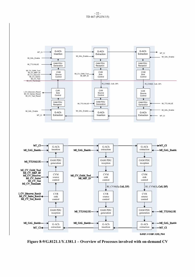
To support on-demand CV, Loopback (LBM/LBR) as described in [ITU-T G.8113.1] clause 8.2.2
is used.
Figure 8-9 provides the different processes inside MEPs and MIPs that are involved in the
Loopback Protocol.
The MEP On-Demand OAM Source insertion process is defined in clause 9.4.1.1, the MEP On-
Demand OAM Sink extraction process in clause 9.4.1.2, the MIP On-Demand OAM Sink
Extraction process in clause 9.4.1.2, and the MIP On-Demand OAM Source insertion process in
clause 9.4.2. In summary, they insert and extract MT_CI OAM signals into and from the stream of
MT_CI_D Traffic Units. The other processes are defined into this clause.
- 22 -
TD 467 (PLEN/15)
G-ACh
Insertion
OAM PDU
Generation
CVM
Source
Control
MI_GAL_Enable
MI_TTLVALUE
CVR
Sink
Control
OAM PDU
Reception
G-ACh
Extraction
MI_GAL_Enable
MT_CI
MT_CI
G-ACh
Extraction
OAM PDU
Reception
CVM
Sink
Control
CVR
Source
Control
OAM PDU
Generation
G-ACh
Extraction
MT_CI
MI_GAL_Enable
MI_TTLVALUE
MI_GAL_Enable
OAM PDU
Reception
CVM
Sink
Control
CVR
Source
Control
OAM PDU
Generation
MI_CV_Discover_Result
MI_CV_Series_Result
MI_CV_Test_Result
MI_CV_OAM_Tool
MI_CV_MEP_ID
MI_CV_Discover
MI_CV_Series
MI_CV_Test
MI_CV_Terminate
MI_GAL_Enable
G-ACh
Extraction
G-ACh
Insertion
MI_TTLVALUE
MI_GAL_Enable
RI_CVM(D, CoS, DP) RI_CVM(D, CoS, DP)
MI_CV_OAM_Tool
MI_MIP_ID
MT_CI
Figure 8-9/G.8121.1/Y.1381.1 – Overview of Processes involved with on-demand CV

- 23 -
TD 467 (PLEN/15)
The on-demand CV Protocol is controlled by the CVM and CMR Control Processes. Two MI
signals that can trigger the LB protocol are defined below:
MI_CV_Series(CoS,N,Length,Period): To send a series of N LB messages to a particular
MEP/MIP; these LB messages are generated every ‘Period’.
MI_CV_Test(CoS,Pattern,Length,Period): To send a series of LB messages carrying a Test
Pattern to a particular MEP; these LB messages are generated every ‘Period’ until the
MI_CV_Test_Terminate signal is received. The CoS parameter is used to set the PHB, and
the Length and Pattern specify the length of the packet and the pattern to use.
The details are described later in this clause.
The CVM Source Control processes to a generated LBM Traffic Unit that is received and
forwarded by MIPs and received by MEPs in the same MEG. The CVM Control process controls
the number of LBM generated and the period between consecutive LBM Traffic Units.
The CVM MIP/MEP Sink control processes the received LBM Traffic Units and as a result the
LBR Generation Process may generate an LBR Traffic Unit in response. The LBR Reception
Process receives and processes the LBR Traffic Units..
The CVM Sink Control processes these received values to determine the result of the requested LB
operation. The result is communicated back using the following MI signals:
MI_CV_Series_Result(REC, ERR, OO): Reports back the total number of received LBR
framepackets (REC), as well as counts of specific errors (ERR):
o OO: Number of LBR Traffic Units that were received out of order (OO).
MI_CV_Test_Result(Sent, REC, CRC, BER, OO): Reports back the total number of LBM
framepackets sent (Sent) as well as the total number of LBR framepackets received (REC);
for the latter counts of specific errors are reported:
o CRC: Number of LBR framepackets where the CRC in the pattern failed.
o BER: Number of LBR framepackets where there was a bit error in the pattern.
o OO: Number of LBR framepackets that were received out of order.
The detailed functionality of the various processes is defined below.
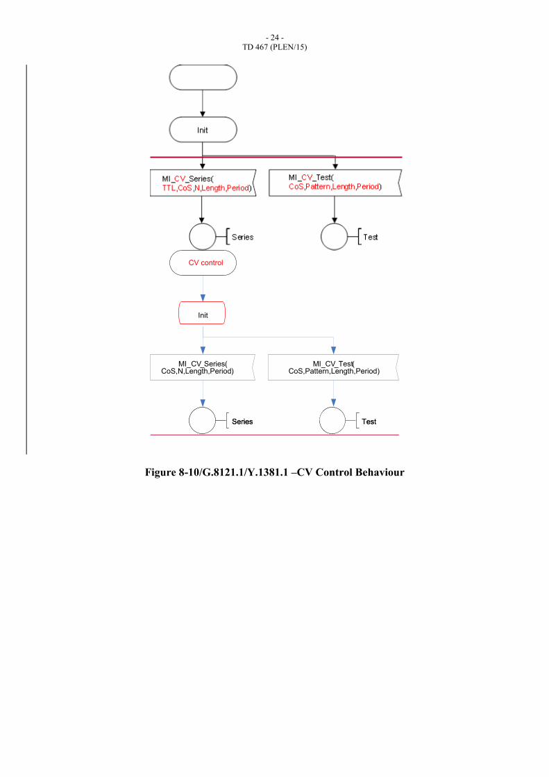
8.8.3.2 CVM Source Control Process
The CVM Source Control Process can receive several MI signals to trigger the LB protocol; this is
shown in Figure 8-10.
Note: CV Control behaviour for Test is for further study.
- 24 -
TD 467 (PLEN/15)
Figure 8-10/G.8121.1/Y.1381.1 –CV Control Behaviour
Init
MI_CV_Series( MI_CV_Test(
SeriesSeries TestTest
CoS,N,Length,Period) CoS,Pattern,Length,Period)
CV control
- 25 -
TD 467 (PLEN/15)
Series
set(0, TxTimer)
OLD_TID=Undef
REC=0
OO=0
Waiting Series
TxTimer
TID++
IF N>1
THENset(Period, TxTimer)
N-
ELSE
set(5s, Timer)
REC++
IF OLD_TID!=Undef
THEN
IF TID!=OLD_TID+1
THEN OO++
OLD_TID=TID
Timer
MI_CV_Series_Result(
REC,OO)
-
TLV=Generate(Length)
InitInitLBM(CoS. DP, TTL, TLV, TID)
RI_CVR(rTLV, TID)

- 26 -
TD 467 (PLEN/15)
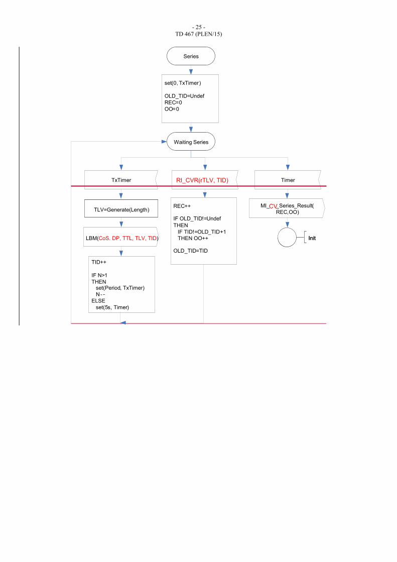
Figure 8-11/G.8121.1/Y.1381.1 – CV Control Series Behaviour
Figure 8-11defines the behaviour of the LB Control Process after the reception of the
MI_CV_Series(TTL, DP ,CoS, N,Length,Period) signal.
The TLV field of the LBM framepackets is determined by the Generate(Length) function.
Generate(Length) generates a Data TLV with length ‘Length’ of arbitrary bit pattern to be included
in the LBM framepacket.
After the receipt of the MI_CV_Series signal, the LBM Generation Process is requested N times to
generate an LBM framepacket (where Period determines the interval between two LBM
framepackets); this is done by issuing the LBM(D, DP, CoS, TLV,TID) signal.
Whenever an RI_CV(rTLV, TID) signal is received, the number of received LBR framepackets is
increased (REC++). If the TID value from the RI_LBR signal does not consecutively follow the last
received TID value, the counter for out of order framepackets is incremented by one (OO++).
Five seconds after sending the last LBM framepacket (i.e., after sending the Nth LBM framepacket)
the REC and OO counters are reported back in the MI_CV_Series_Result signal.
Series
set(0, TxTimer)
OLD_TID=Undef
REC=0
OO=0
Waiting Series
TxTimer
TID++
IF N>1
THENset(Period, TxTimer)
N-
ELSE
set(5s, Timer)
REC++
IF OLD_TID!=Undef
THEN
IF TID!=OLD_TID+1
THEN OO++
OLD_TID=TID
Timer
MI_CV_Series_Result(
REC,OO)
-
TLV=Generate(Length)
InitInitLBM(CoS. DP, TLV, TID)
RI_CVR(rTLV, TID)
- 27 -
TD 467 (PLEN/15)
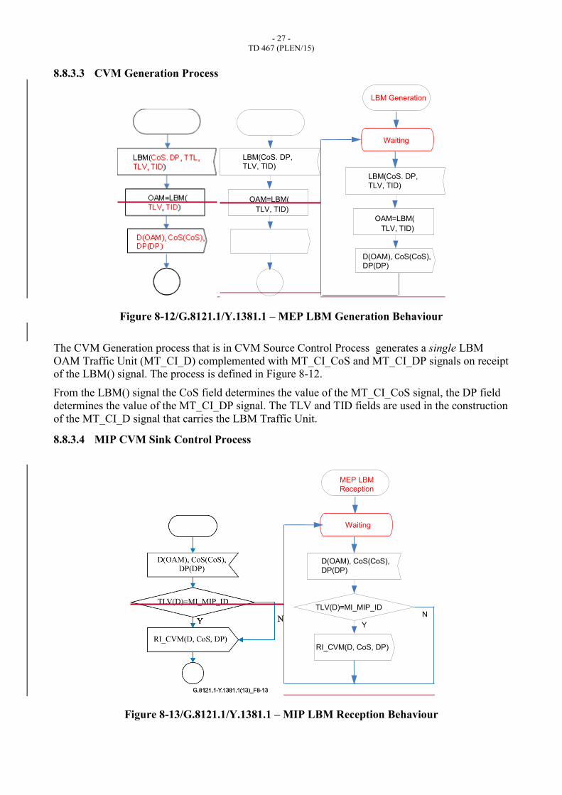
8.8.3.3 CVM Generation Process
Figure 8-12/G.8121.1/Y.1381.1 – MEP LBM Generation Behaviour
The CVM Generation process that is in CVM Source Control Process generates a single LBM
OAM Traffic Unit (MT_CI_D) complemented with MT_CI_CoS and MT_CI_DP signals on receipt
of the LBM() signal. The process is defined in Figure 8-12.
From the LBM() signal the CoS field determines the value of the MT_CI_CoS signal, the DP field
determines the value of the MT_CI_DP signal. The TLV and TID fields are used in the construction
of the MT_CI_D signal that carries the LBM Traffic Unit.
8.8.3.4 MIP CVM Sink Control Process
Figure 8-13/G.8121.1/Y.1381.1 – MIP LBM Reception Behaviour
OAM=LBM(
TLV, TID)
LBM(CoS. DP,
TLV, TID)
OAM=LBM(
TLV, TID)
LBM(CoS. DP,
TLV, TID)
D(OAM), CoS(CoS),
DP(DP)
LBM Generation
Waiting
Y
NTLV(D)=MI_MIP_ID
RI_CVM(D, CoS, DP)
D(OAM), CoS(CoS),
DP(DP)
MEP LBM
Reception
Waiting
- 28 -
TD 467 (PLEN/15)
The MIP CVM Sink Control Process receives MT_CI Traffic Units containing LBM PDUs
complemented by the P and D signals.
The behaviour is defined in Figure 8-13. If TLV(D) equals MI_MIP_ID, the Loopback is intended
for this MIP and the information is forwarded to the Loopback Reply Generation Process using the
RI_CVM(D,DP,CoS) signal; otherwise the information is ignored and no action is taken.
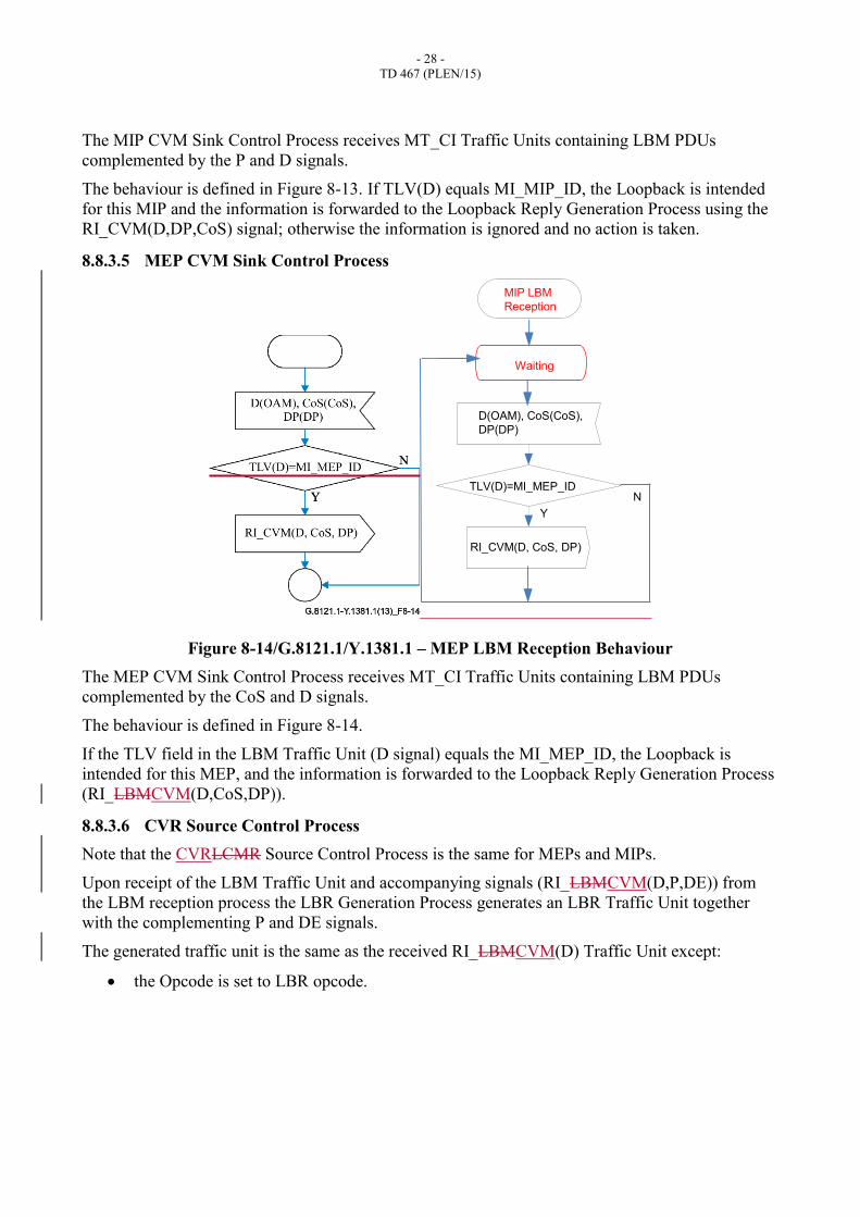
8.8.3.5 MEP CVM Sink Control Process
Figure 8-14/G.8121.1/Y.1381.1 – MEP LBM Reception Behaviour
The MEP CVM Sink Control Process receives MT_CI Traffic Units containing LBM PDUs
complemented by the CoS and D signals.
The behaviour is defined in Figure 8-14.
If the TLV field in the LBM Traffic Unit (D signal) equals the MI_MEP_ID, the Loopback is
intended for this MEP, and the information is forwarded to the Loopback Reply Generation Process
(RI_LBMCVM(D,CoS,DP)).
8.8.3.6 CVR Source Control Process
Note that the CVRLCMR Source Control Process is the same for MEPs and MIPs.
Upon receipt of the LBM Traffic Unit and accompanying signals (RI_LBMCVM(D,P,DE)) from
the LBM reception process the LBR Generation Process generates an LBR Traffic Unit together
with the complementing P and DE signals.
The generated traffic unit is the same as the received RI_LBMCVM(D) Traffic Unit except:
the Opcode is set to LBR opcode.
Y
TLV(D)=MI_MEP_ID
RI_CVM(D, CoS, DP)
D(OAM), CoS(CoS),
DP(DP)
MIP LBM
Reception
Waiting
N
- 29 -
TD 467 (PLEN/15)
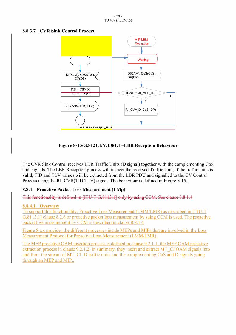
8.8.3.7 CVR Sink Control Process
Figure 8-15/G.8121.1/Y.1381.1 –LBR Reception Behaviour
The CVR Sink Control receives LBR Traffic Units (D signal) together with the complementing CoS
and signals. The LBR Reception process will inspect the received Traffic Unit; if the traffic units is
valid, TID and TLV values will be extracted from the LBR PDU and signalled to the CV Control
Process using the RI_CVR(TID,TLV) signal. The behaviour is defined in Figure 8-15.
8.8.4 Proactive Packet Loss Measurement (LMp)
This functionality is defined in [ITU-T G.8113.1] only by using CCM. See clause 8.8.1.4
8.8.4.1 Overview
To support this functionality, Proactive Loss Measurement (LMM/LMR) as described in [ITU-T
G.8113.1] clause 8.2.6 or proactive packet loss measurement by suing CCM is used. The proactive
packet loss measurement by CCM is described in clause 8.8.1.4
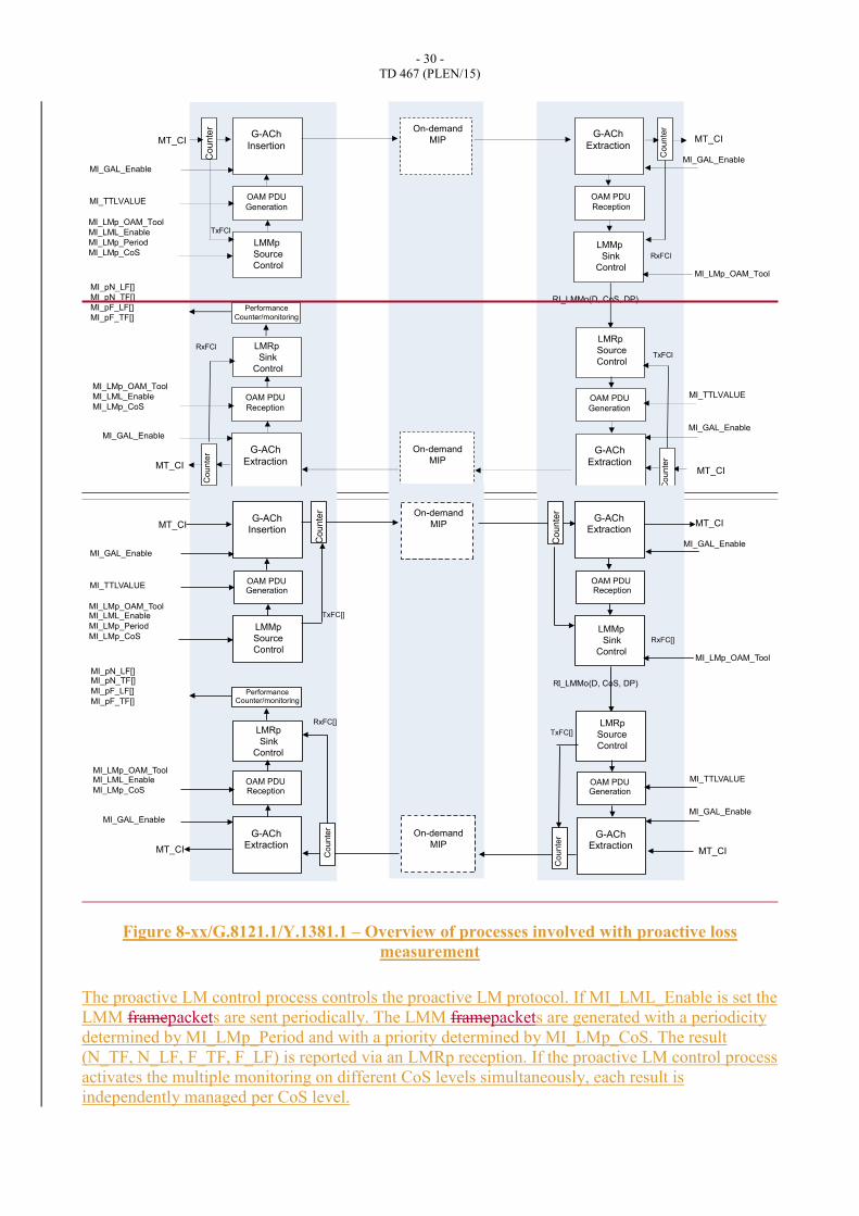
Figure 8-xx provides the different processes inside MEPs and MIPs that are involved in the Loss
Measurement Protocol for Proactive Loss Measurement (LMM/LMR).
The MEP proactive OAM insertion process is defined in clause 9.2.1.1, the MEP OAM proactive
extraction process in clause 9.2.1.2. In summary, they insert and extract MT_CI OAM signals into
and from the stream of MT_CI_D traffic units and the complementing CoS and D signals going
through an MEP and MIP..
Y
TLV(D)=MI_MEP_ID
RI_CVM(D, CoS, DP)
D(OAM), CoS(CoS),
DP(DP)
MIP LBM
Reception
Waiting
N
- 30 -
TD 467 (PLEN/15)
Figure 8-xx/G.8121.1/Y.1381.1 – Overview of processes involved with proactive loss
measurement
The proactive LM control process controls the proactive LM protocol. If MI_LML_Enable is set the
LMM framepackets are sent periodically. The LMM framepackets are generated with a periodicity
determined by MI_LMp_Period and with a priority determined by MI_LMp_CoS. The result
(N_TF, N_LF, F_TF, F_LF) is reported via an LMRp reception. If the proactive LM control process
activates the multiple monitoring on different CoS levels simultaneously, each result is
independently managed per CoS level.
G-ACh
Insertion
OAM PDU
Generation
LMMp
Source
Control
MI_GAL_Enable
MI_TTLVALUE
LMRp
Sink
Control
OAM PDU
Reception
G-ACh
Extraction
MI_GAL_Enable
Co
un
ter
MT_CI
MT_CI
G-ACh
Extraction
OAM PDU
Reception
OAM PDU
Generation
G-ACh
Extraction
MT_CI
Co
un
ter
Co
un
ter
On-demand
MIP
On-demand
MIP
MI_LMp_OAM_Tool
MI_LML_Enable
MI_LMp_Period
MI_LMp_CoS
LMRp
Source
Control
RI_LMMo(D, CoS, DP)
LMMp
Sink
Control
MI_GAL_Enable
MI_GAL_Enable
MI_TTLVALUE
Counte
r
TxFCl
TxFCl
RxFCl
RxFCl
MT_CI
MI_pN_LF[]
MI_pN_TF[]
MI_pF_LF[]
MI_pF_TF[]Performance
Counter/monitoring
MI_LMp_OAM_Tool
MI_LMp_OAM_Tool
MI_LML_Enable
MI_LMp_CoS
G-ACh Insertion
OAM PDU Generation
LMMp
Source
Control
MI_GAL_Enable
MI_TTLVALUE
LMRp
Sink
Control
OAM PDU Reception
G-ACh Extraction
MI_GAL_Enable
MT_CI
MT_CI
G-ACh Extraction
OAM PDU Reception
OAM PDU Generation
G-ACh Extraction
MT_CI
On-demand
MIP
On-demand
MIP
MI_LMp_OAM_Tool MI_LML_Enable
MI_LMp_Period
MI_LMp_CoS
LMRp
Source
Control
RI_LMMo(D, CoS, DP)
LMMp
Sink
Control
MI_GAL_Enable
MI_GAL_Enable
MI_TTLVALUE
TxFC[]
TxFC[]
RxFC[]
RxFC[]
MT_CI
MI_pN_LF[] MI_pN_TF[]
MI_pF_LF[]
MI_pF_TF[] Performance
Counter/monitoring
MI_LMp_OAM_Tool
MI_LMp_OAM_Tool MI_LML_Enable
MI_LMp_CoS
Counte
r
Counte
r
Co
un
ter
Cou
nte
r

- 31 -
TD 467 (PLEN/15)
The behaviour of the processes is defined below.
8.8.4.2 Proactive LM Source Control Process
The behaviour of the proactive LM control process is defined in Figure 8-xx+1. If the
MI_LML_Enable is asserted, the process starts to generate LMM framepackets. The result (N_TF,
N_LF, F_TF, F_LF) is reported via an LMR reception.

- 32 -
TD 467 (PLEN/15)
Disabled
MI_LML_Enable
Enabled
Timer
LMMp(
Set(0,Timer)
Set(MI_LMp_Period,Timer)
!MI_LML_Enable
MI_LMp_CoS )
TxFCb_svd=TxFCbTxFCb_svd=TxFCb
TxFCf_svd=TxFCf
RxFCf_svd =RxFCf
TxFCf_svd=TxFCf
RxFCf_svd =RxFCf
RxFCl_svd=RxFCl
saved=true
RI_LM_Result(
N_TF,N_LF, F_TF, F_LF)
N_TF= | TxFCb-TxFCb_svd|
N_LF= | TxFCb-TxFCb_svd| - |RxFCl-RxFCl_svd|
F_TF= | TxFCf-TxFCf_svd|
F_LF= | TxFCf-TxFCf_svd| - |RxFCf-RxFCf_svd|
RI_LMRp(TxFCf,
RxFCf,TxFCb,RxFCl)
N_TF=N_LF=0F_TF=F_LF=0
TxFCf_svd=TxFCb_svd=0
RxFCf_svd=RxFCl_svd=0
saved=false
Y
Nsaved
Enabled
Enabled

- 33 -
TD 467 (PLEN/15)
Figure 8-xx+1/G.8121.1/Y.1381.1 – Proactive LM control behaviour
Disabled
MI_LML_Enable
Enabled
Timer
LMMp(
Set(0,Timer)
Set(MI_LMp_Period,Timer)
!MI_LML_Enable
MI_LMp_CoS )
TxFCb_svd=TxFCbTxFCb_svd=TxFCb
TxFCf_svd=TxFCf
RxFCf_svd =RxFCf
TxFCf_svd=TxFCf
RxFCf_svd =RxFCf
RxFCl_svd=RxFCl
saved=true
RI_LM_Result(
N_TF,N_LF, F_TF, F_LF)
N_TF= | TxFCb-TxFCb_svd|
N_LF= | TxFCb-TxFCb_svd| - |RxFCl-RxFCl_svd|
F_TF= | TxFCf-TxFCf_svd|
F_LF= | TxFCf-TxFCf_svd| - |RxFCf-RxFCf_svd|
RI_LMRp(TxFCf,
RxFCf,TxFCb,RxFCl)
N_TF=N_LF=0F_TF=F_LF=0
TxFCf_svd=TxFCb_svd=0
RxFCf_svd=RxFCl_svd=0
saved=false
Y
Nsaved
Proactive
LM control

- 34 -
TD 467 (PLEN/15)
8.8.4.3 Proactive LMM generation process
The behaviour of the LMMp generation process that is in LMMp Source control process is defined
in Figure 8-xx+2.
Figure 8-xx+2/ G.8121.1/Y.1381.1 – LMM generation behaviour
Upon receiving the LMM(CoS), a single LMM traffic unit is generated together with the
complementing CoS and DP(0) signals.
8.8.4.4 Proactive LMM Reception Process
The proactive LMM reception process that is in proactive DMM Sink control process processes the
received proactive LMM traffic units and the complementing CoS and DP signals. The behaviour is
defined in Figure 8-xx+3.
LMMp(CoS)
LMMp.D(OAM),
LMMp.CoS(CoS)
LMMp.DP(0)
Waiting
OAM=LMMp
(CoS,
TxFC[p]
)
LMMp(CoS)
LMMp.D(OAM),
LMMp.CoS(CoS)
LMMp.DP(0)
Waiting
OAM=LMMp
(CoS,
TxFC[p]
)
LMMp
generation

- 35 -
TD 467 (PLEN/15)
Figure 8-xx+3/ G.8121.1/Y.1381.1 – LMM reception behaviour
Traffic Unit and the complementing CoS and DP signals are forwarded as Remote Information to
the LMR Generation Process.
8.8.4.5 Proactive LMR Generation Process
The Proactive LMR Generation Process that is in DMRp Source control process generates a LMRp
Traffic Unit and its complementing CoS and DP signals. The behaviour is defined in Figure 8-xx+4.
Figure 8-xx+4/ G.8121.1/Y.1381.1 – LMR generation behaviour
RI_LMMp(OAM, CoS, DP)
RxFCf (OAM)=RxFC[P]
Y
Waiting
LMMp.D(OAM),
LMMp.CoS(CoS)
LMMp.DP(0)
RI_LMMp(OAM, CoS, DP)
RxFCf(OAM)=RxFC[P]
Y
Waiting
LMMp.D(OAM),
LMMp.CoS(CoS)
LMMp.DP(0)
LMMp
Reception
Waiting
RI_LMMp(OAM, CoS, DP)
LMRp.D(OAM),
LMRp.CoS(CoS)
LMRp.DP(0)
OPC(OAM)=LMRp
TxFCb=TxFC[P]
Waiting
RI_LMMp(OAM, CoS, DP)
LMRp.D(OAM),
LMRp.CoS(CoS)
LMRp.DP(DP)
OPC(OAM)=LMRp
TxFCb=TxFC[P]
LMRp
Generation
- 36 -
TD 467 (PLEN/15)
Upon the receipt of Remote Information containing a LMMp Traffic Unit, the LMRp generation
process generates a DMR Traffic Unit and forwards it to the OAM insertion Process.
As part of the DMR generation the:
– The Opcode is changed into DMRp Opcode;
– the TxFCb field is assigned the value of the Tx counter..
– All the other fields are copied from the Remote Information containing the original DMMp
Traffic Unit.
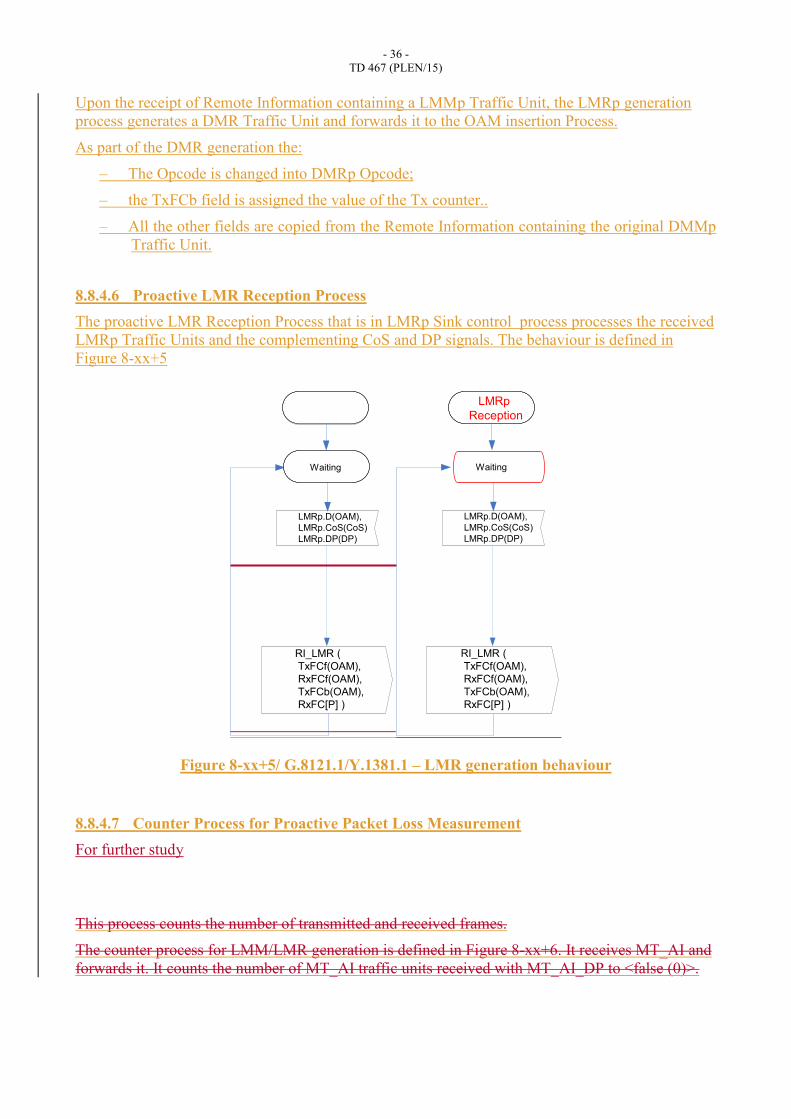
8.8.4.6 Proactive LMR Reception Process
The proactive LMR Reception Process that is in LMRp Sink control process processes the received
LMRp Traffic Units and the complementing CoS and DP signals. The behaviour is defined in
Figure 8-xx+5
Figure 8-xx+5/ G.8121.1/Y.1381.1 – LMR generation behaviour
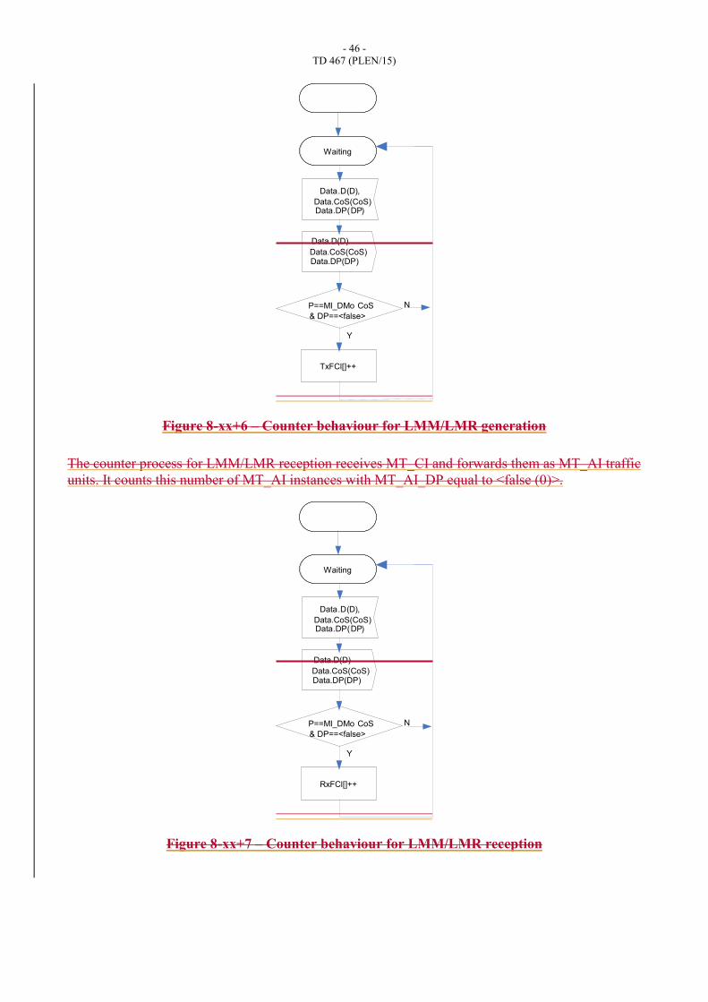
8.8.4.7 Counter Process for Proactive Packet Loss Measurement
For further study
This process counts the number of transmitted and received frames.
The counter process for LMM/LMR generation is defined in Figure 8-xx+6. It receives MT_AI and
forwards it. It counts the number of MT_AI traffic units received with MT_AI_DP to <false (0)>.
RI_LMR (
TxFCf(OAM),
RxFCf(OAM),
TxFCb(OAM),
RxFC[P] )
Waiting
LMRp.D(OAM),
LMRp.CoS(CoS)
LMRp.DP(DP)
RI_LMR (
TxFCf(OAM),
RxFCf(OAM),
TxFCb(OAM),
RxFC[P] )
Waiting
LMRp.D(OAM),
LMRp.CoS(CoS)
LMRp.DP(DP)
LMRp
Reception

- 37 -
TD 467 (PLEN/15)
Figure 8-xx+6 – Counter behaviour for LMM/LMR generation
The counter process for LMM/LMR reception is defined in Figure 8-xx+7. It receives MT_CI and
forwards them as MT_AI traffic units. It counts this number of MT_AI instances with MT_AI_DP
equal to <false (0)>.
Figure 8-xx+7 – Counter behaviour for LMM/LMR reception
Data.D(D),
Data.DP(DP)
Y
N
TxFCl[]++
& DP==<false>
Data.CoS(CoS)
P==MI_DMp CoS
Waiting
Data.CoS(CoS)Data.DP(DP)
Data.D(D)
Data.D(D),
Data.DP(DP)
Y
N
RxFCl[]++
& DP==<false>
Data.CoS(CoS)
P==MI_DMp CoS
Waiting
Data.CoS(CoS)Data.DP(DP)
Data.D(D)
- 38 -
TD 467 (PLEN/15)
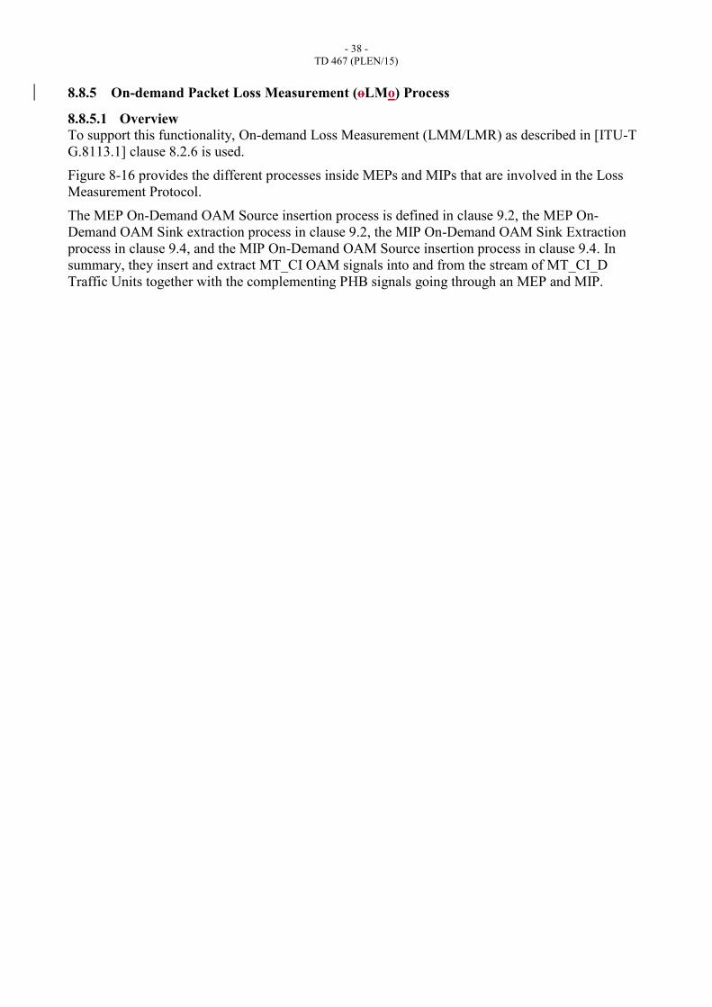
8.8.5 On-demand Packet Loss Measurement (oLMo) Process
8.8.5.1 Overview
To support this functionality, On-demand Loss Measurement (LMM/LMR) as described in [ITU-T
G.8113.1] clause 8.2.6 is used.
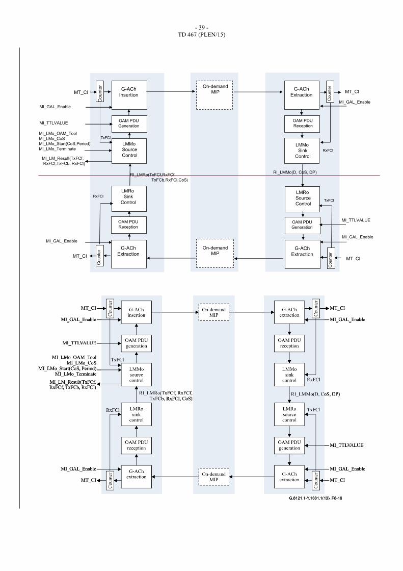
Figure 8-16 provides the different processes inside MEPs and MIPs that are involved in the Loss
Measurement Protocol.
The MEP On-Demand OAM Source insertion process is defined in clause 9.2, the MEP On-
Demand OAM Sink extraction process in clause 9.2, the MIP On-Demand OAM Sink Extraction
process in clause 9.4, and the MIP On-Demand OAM Source insertion process in clause 9.4. In
summary, they insert and extract MT_CI OAM signals into and from the stream of MT_CI_D
Traffic Units together with the complementing PHB signals going through an MEP and MIP.
- 39 -
TD 467 (PLEN/15)
G-ACh
Insertion
OAM PDU
Generation
LMMo
Source
Control
MI_GAL_Enable
MI_TTLVALUE
LMRo
Sink
Control
OAM PDU
Reception
G-ACh
Extraction
MI_GAL_Enable
Counte
r
MT_CI
MT_CI
G-ACh
Extraction
OAM PDU
Reception
OAM PDU
Generation
G-ACh
Extraction
MT_CI
Co
un
ter
Co
un
ter
On-demand
MIP
On-demand
MIP
MI_LMo_OAM_Tool
MI_LMo_CoS
MI_LMo_Start(CoS,Period)
MI_LMo_Terminate
MI_LM_Result(TxFCf,
RxFCf,TxFCb, RxFCl)
LMRo
Source
Control
RI_LMMo(D, CoS, DP)
LMMo
Sink
Control
RI_LMRo(TxFCf,RxFCf,
TxFCb,RxFCl,CoS)
MI_GAL_Enable
MI_GAL_Enable
MI_TTLVALUE
Co
un
ter
TxFCl
TxFCl
RxFCl
RxFCl
MT_CI

- 40 -
TD 467 (PLEN/15)
Figure 8-16 G.8121.1/Y.1381.1 – Overview of Processes involved with On-demand Loss
Measurement
The LMMo source control process controls the LM protocol. The protocol is activated upon receipt
of the MI_LMo_Start(CoS,Period) signal and remains activated until the MI_LMo_Terminate
signal is received.
The result is communicated via the MI_LMo_Result(N_TF, N_LF, F_TF, F_LF) signal.
The LMMo Source control Protocol generates an LMM Traffic Unit that passes transparently
through MIPs, but that will be processed by the LMMo Sink control Process in MEPs. The LMRo
Source Process generates an LMR Traffic Unit in response to the receipt of an LMMo Traffic Unit.
The LMRo Reception process receives and processes the LMRo Traffic Units.
The behaviour of the processes is defined below.
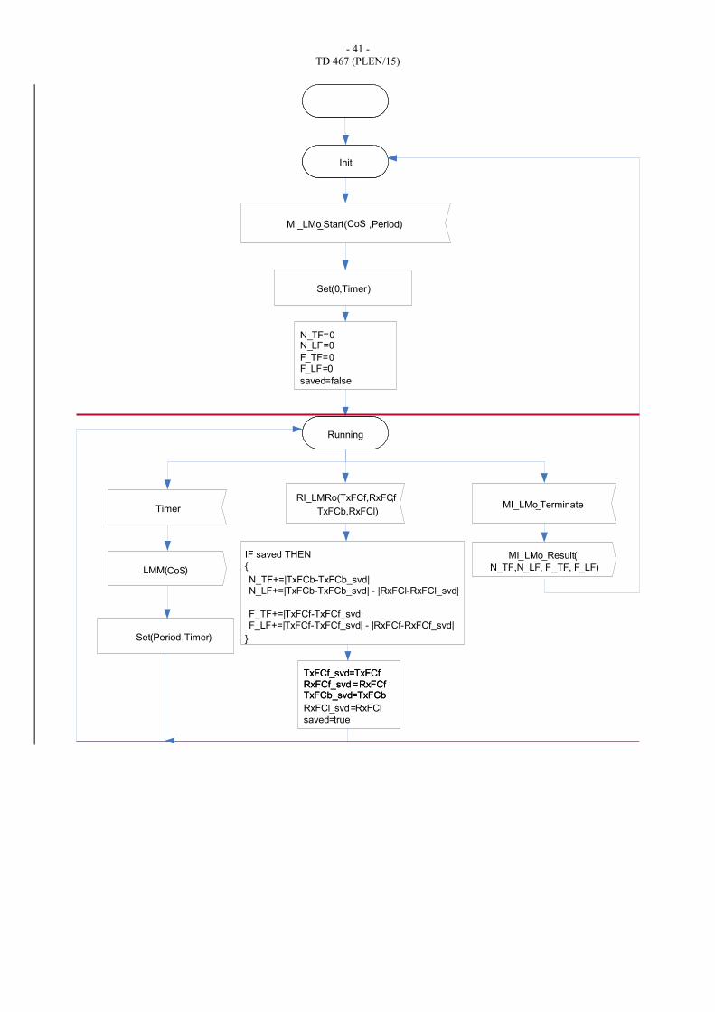
8.8.5.2 On-demand LM Source Control Process
The behaviour of the LMMo Source Control Process is defined in Figure 8-17.
- 41 -
TD 467 (PLEN/15)
Init
MI_LMo_Start( ,Period)
MI_LMo_Terminate
Running
Timer
LMM( )
IF saved THEN{
}
TxFCb_svd=TxFCbTxFCb_svd=TxFCb
TxFCf_svd=TxFCfRxFCf_svd =RxFCfTxFCf_svd=TxFCfRxFCf_svd =RxFCf
RxFCl_svd=RxFCl
saved=true
MI_LMo_Result(
N_TF,N_LF, F_TF, F_LF)
N_TF=0N_LF=0
F_TF=0F_LF=0
saved=false
Set(0,Timer)
Set(Period,Timer)
N_TF+=|TxFCb-TxFCb_svd|N_LF+=|TxFCb-TxFCb_svd| - |RxFCl-RxFCl_svd|
F_TF+=|TxFCf-TxFCf_svd|F_LF+=|TxFCf-TxFCf_svd| - |RxFCf-RxFCf_svd|
RI_LMRo(TxFCf,RxFCf,
TxFCb,RxFCl)
CoS
CoS
- 42 -
TD 467 (PLEN/15)
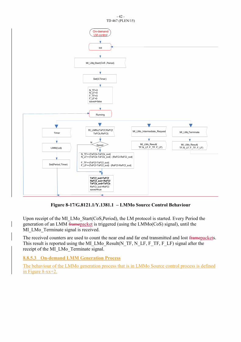
Figure 8-17/G.8121.1/Y.1381.1 – LMMo Source Control Behaviour
Upon receipt of the MI_LMo_Start(CoS,Period), the LM protocol is started. Every Period the
generation of an LMM framepacket is triggered (using the LMMo(CoS) signal), until the
MI_LMo_Terminate signal is received.
The received counters are used to count the near end and far end transmitted and lost framepackets.
This result is reported using the MI_LMo_Result(N_TF, N_LF, F_TF, F_LF) signal after the
receipt of the MI_LMo_Terminate signal.
8.8.5.3 On-demand LMM Generation Process
The behaviour of the LMMo generation process that is in LMMo Source control process is defined
in Figure 8-xx+2.
Init
MI_LMo_Start( ,Period)
MI_LMo_Intermediate_Request
Running
Timer
LMM( )
TxFCb_svd=TxFCbTxFCb_svd=TxFCb
TxFCf_svd=TxFCfRxFCf_svd=RxFCfTxFCf_svd=TxFCfRxFCf_svd=RxFCf
RxFCl_svd=RxFCl
saved=true
MI_LMo_Result(
TF,N_LF, F_TF, F_LF)
N_TF=0N_LF=0
F_TF=0F_LF=0
saved=false
Set(0,Timer)
Set(Period,Timer)
N_TF+=|TxFCb-TxFCb_svd|N_LF+=|TxFCb-TxFCb_svd| - |RxFCl-RxFCl_svd|
F_TF+=|TxFCf-TxFCf_svd|F_LF+=|TxFCf-TxFCf_svd| - |RxFCf-RxFCf_svd|
RI_LMRo(TxFCf,RxFCf,
TxFCb,RxFCl)
CoS
CoS
On-demand
LM control
Saved
Y
N
MI_LMo_Terminate
MI_LMo_Result(
TF,N_LF, F_TF, F_LF)
- 43 -
TD 467 (PLEN/15)
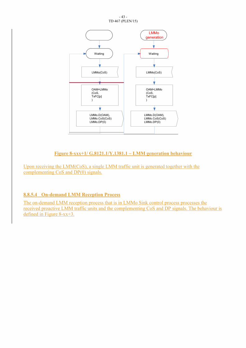
Figure 8-xxx+1/ G.8121.1/Y.1381.1 – LMM generation behaviour
Upon receiving the LMM(CoS), a single LMM traffic unit is generated together with the
complementing CoS and DP(0) signals.
8.8.5.4 On-demand LMM Reception Process
The on-demand LMM reception process that is in LMMo Sink control process processes the
received proactive LMM traffic units and the complementing CoS and DP signals. The behaviour is
defined in Figure 8-xx+3.
LMMo(CoS)
LMMo.D(OAM),
LMMo.CoS(CoS)
LMMo.DP(0)
Waiting
OAM=LMMo
(CoS,
TxFC[p]
)
LMMo(CoS)
LMMo.D(OAM),
LMMo.CoS(CoS)
LMMo.DP(0)
Waiting
OAM=LMMo
(CoS,
TxFC[p]
)
LMMo
generation
- 44 -
TD 467 (PLEN/15)
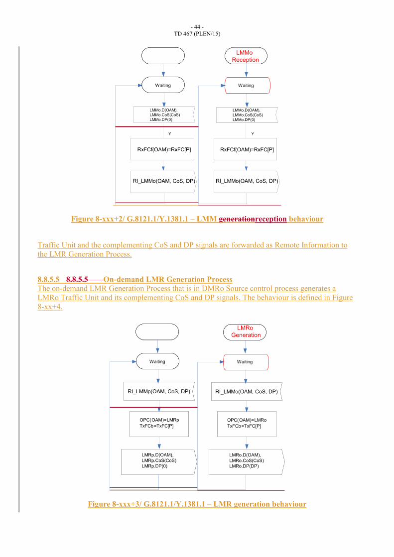
Figure 8-xxx+2/ G.8121.1/Y.1381.1 – LMM generationreception behaviour
Traffic Unit and the complementing CoS and DP signals are forwarded as Remote Information to
the LMR Generation Process.
8.8.5.5 8.8.5.5 On-demand LMR Generation Process
The on-demand LMR Generation Process that is in DMRo Source control process generates a
LMRo Traffic Unit and its complementing CoS and DP signals. The behaviour is defined in Figure
8-xx+4.
Figure 8-xxx+3/ G.8121.1/Y.1381.1 – LMR generation behaviour
RI_LMMo(OAM, CoS, DP)
RxFCf(OAM)=RxFC[P]
Y
Waiting
LMMo.D(OAM),
LMMo.CoS(CoS)
LMMo.DP(0)
RI_LMMo(OAM, CoS, DP)
RxFCf(OAM)=RxFC[P]
Y
Waiting
LMMo.D(OAM),
LMMo.CoS(CoS)
LMMo.DP(0)
LMMo
Reception
Waiting
RI_LMMp(OAM, CoS, DP)
LMRp.D(OAM),
LMRp.CoS(CoS)
LMRp.DP(0)
OPC(OAM)=LMRp
TxFCb=TxFC[P]
Waiting
RI_LMMo(OAM, CoS, DP)
LMRo.D(OAM),
LMRo.CoS(CoS)
LMRo.DP(DP)
OPC(OAM)=LMRo
TxFCb=TxFC[P]
LMRo
Generation
- 45 -
TD 467 (PLEN/15)
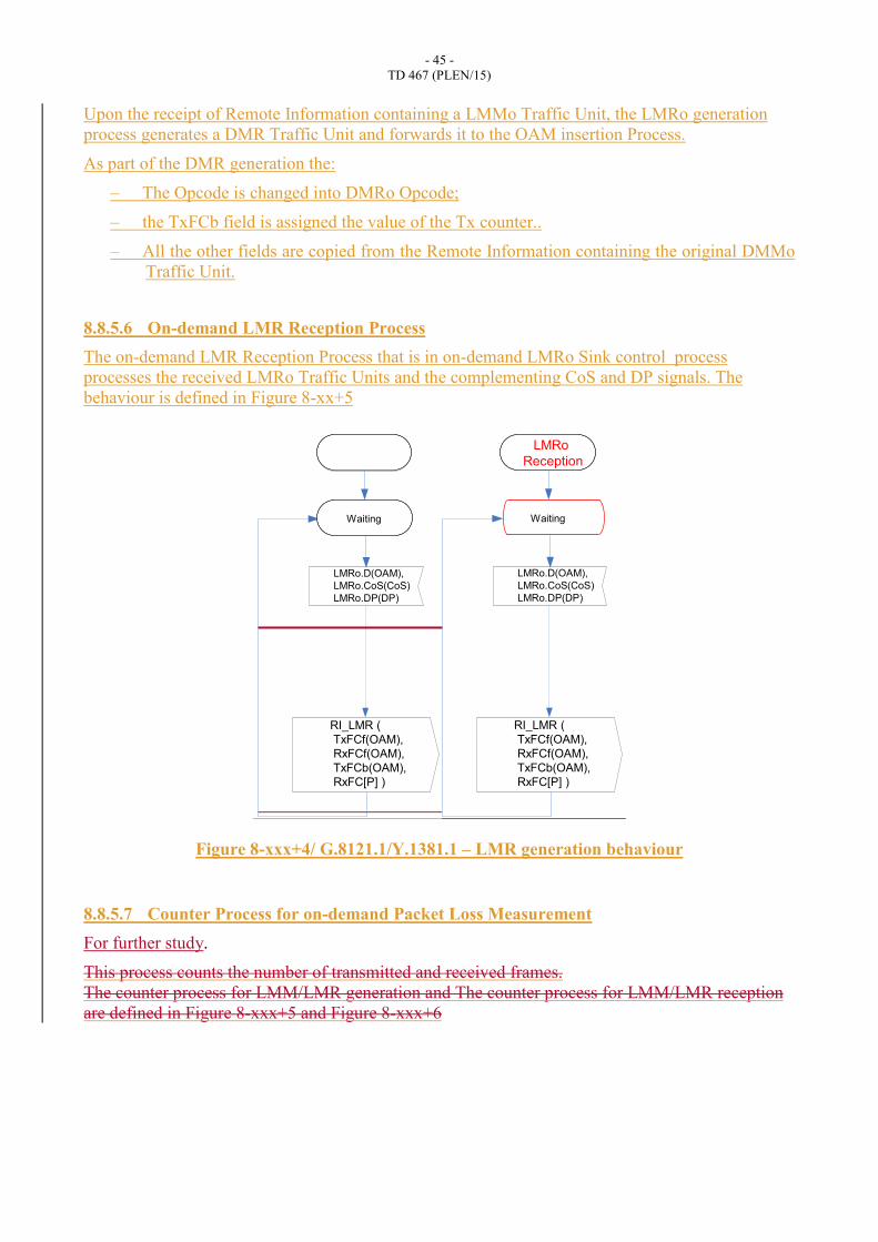
Upon the receipt of Remote Information containing a LMMo Traffic Unit, the LMRo generation
process generates a DMR Traffic Unit and forwards it to the OAM insertion Process.
As part of the DMR generation the:
– The Opcode is changed into DMRo Opcode;
– the TxFCb field is assigned the value of the Tx counter..
– All the other fields are copied from the Remote Information containing the original DMMo
Traffic Unit.
8.8.5.6 On-demand LMR Reception Process
The on-demand LMR Reception Process that is in on-demand LMRo Sink control process
processes the received LMRo Traffic Units and the complementing CoS and DP signals. The
behaviour is defined in Figure 8-xx+5
Figure 8-xxx+4/ G.8121.1/Y.1381.1 – LMR generation behaviour
8.8.5.7 Counter Process for on-demand Packet Loss Measurement
For further study.
This process counts the number of transmitted and received frames.
The counter process for LMM/LMR generation and The counter process for LMM/LMR reception
are defined in Figure 8-xxx+5 and Figure 8-xxx+6
RI_LMR (
TxFCf(OAM),
RxFCf(OAM),
TxFCb(OAM),
RxFC[P] )
Waiting
LMRo.D(OAM),
LMRo.CoS(CoS)
LMRo.DP(DP)
RI_LMR (
TxFCf(OAM),
RxFCf(OAM),
TxFCb(OAM),
RxFC[P] )
Waiting
LMRo.D(OAM),
LMRo.CoS(CoS)
LMRo.DP(DP)
LMRo
Reception
- 46 -
TD 467 (PLEN/15)
Figure 8-xx+6 – Counter behaviour for LMM/LMR generation
The counter process for LMM/LMR reception receives MT_CI and forwards them as MT_AI traffic
units. It counts this number of MT_AI instances with MT_AI_DP equal to <false (0)>.
Figure 8-xx+7 – Counter behaviour for LMM/LMR reception
Data.D(D),
Data.DP(DP)
Y
N
TxFCl[]++
& DP==<false>
Data.CoS(CoS)
P==MI_DMo CoS
Waiting
Data.CoS(CoS)Data.DP(DP)
Data.D(D)
Data.D(D),
Data.DP(DP)
Y
N
RxFCl[]++
& DP==<false>
Data.CoS(CoS)
P==MI_DMo CoS
Waiting
Data.CoS(CoS)Data.DP(DP)
Data.D(D)

- 47 -
TD 467 (PLEN/15)
8.8.5.3 On-demand LMx Generation Process
The LMx Generation Process contains both the LMMo Generation functionality in LMMo Source
control process and LMRo Generation functionality in LMRo Source control process .
Figure 8-18 defines the behaviour of the LMx Process. The behaviour consists of three parts:
– LMMo Generation part that is triggered by the receipt of the LMMo(CoS) signal;
– LMRo Generation part that is triggered by the receipt of RI_LMMo(D,CoS,DP) signals;
– Counter part that is triggered by the receipt of a normal data signal.
Figure 8-18/G.8121.1/Y.1381.1 – On-demand LMx Generation Behaviour
Counter Part
This part receives MT_AI and forwards it. It counts the number of MT_AI traffic units received
with MT_AI_P signal equal to MIo_LM_CoS and MT_AI_DP to <false (0)>.
LMMo Generation Part
This part generates an LMMo Traffic Unit on receipt of the LMMo (D, CoS, DP) signal.
8.8.5.4 On-demand LMx Reception Process
The On-demand LMx Reception Process contains both the LMMo Reception functionality in
LMMo Sink control process and LMRo Reception functionality in LMRo Sink control process.
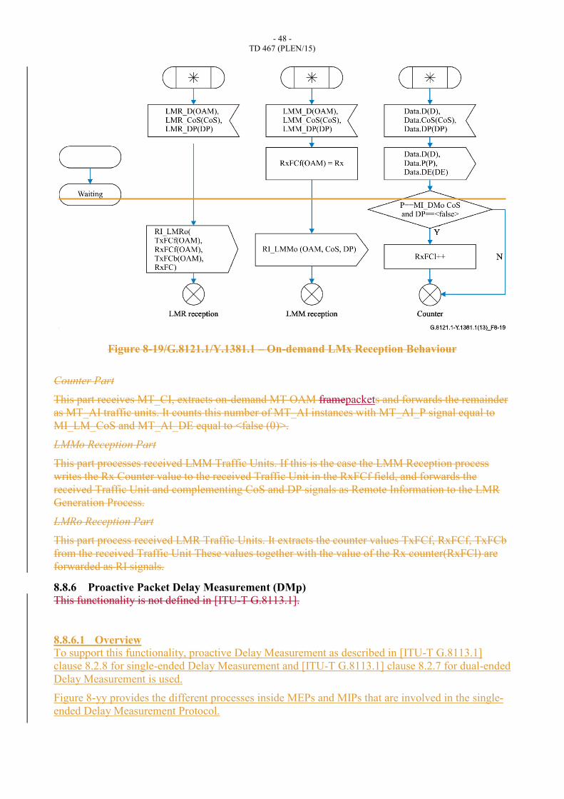
Figure 8-19 defines the behaviour of the LMx Reception Process. The behaviour consists of three
parts:
– LMM Reception part that is triggered by the receipt of an LMM Traffic Unit;
– LMR Reception part that is triggered by the receipt of an LMR Traffic Unit;
– Counter part that is triggered by the receipt of a normal data signal.
- 48 -
TD 467 (PLEN/15)
Figure 8-19/G.8121.1/Y.1381.1 – On-demand LMx Reception Behaviour
Counter Part
This part receives MT_CI, extracts on-demand MT OAM framepackets and forwards the remainder
as MT_AI traffic units. It counts this number of MT_AI instances with MT_AI_P signal equal to
MI_LM_CoS and MT_AI_DE equal to <false (0)>.
LMMo Reception Part
This part processes received LMM Traffic Units. If this is the case the LMM Reception process
writes the Rx Counter value to the received Traffic Unit in the RxFCf field, and forwards the
received Traffic Unit and complementing CoS and DP signals as Remote Information to the LMR
Generation Process.
LMRo Reception Part
This part process received LMR Traffic Units. It extracts the counter values TxFCf, RxFCf, TxFCb
from the received Traffic Unit These values together with the value of the Rx counter(RxFCl) are
forwarded as RI signals.
8.8.6 Proactive Packet Delay Measurement (DMp)
This functionality is not defined in [ITU-T G.8113.1].
8.8.6.1 Overview
To support this functionality, proactive Delay Measurement as described in [ITU-T G.8113.1]
clause 8.2.8 for single-ended Delay Measurement and [ITU-T G.8113.1] clause 8.2.7 for dual-ended
Delay Measurement is used.
Figure 8-yy provides the different processes inside MEPs and MIPs that are involved in the single-
ended Delay Measurement Protocol.

- 49 -
TD 467 (PLEN/15)
The MEP proactive OAM insertion process is defined in clause 9.2.1.1, the MEP OAM proactive
extraction process in clause 9.2.1.2. In summary, they insert and extract MT_CI OAM signals into
and from the stream of MT_CI_D traffic units and the complementing CoS and D signals going
through an MEP and MIP; the extraction is based on OAM_Tool.
Figure 8-yy – Overview of processes involved with proactive single-ended delay measurement
The proactive DM control process controls the proactive DM protocol. If MI_DMp_Enable is set
the DMM framepackets are sent periodically. The DMM framepackets are generated with a
periodicity determined by MI_DMp_Period and with a priority determined by MI_DMp_CoS. The
result (B_FD, F_FD, N_FD) is reported via a DMRp Sink Control process . If the proactive DM
control process activates the multiple monitoring on different CoS levels simultaneously, each
result is independently managed per CoS level. Optional test ID TLVs can be utilized to distinguish
each measurement if multiple measurements are simultaneously activated in an ME.
[Contributor’s note: test ID TLV is not considered in G.8113.1]
Figure 8-zz provides the different processes inside MEPs and MIPs that are involved with proactive
dual-ended delay measurement
G-ACh
Insertion
OAM PDU
Generation
DMMp
Source
Control
MI_GAL_Enable
MI_TTLVALUE
DMRp
Sink
Control
OAM PDU
Reception
G-ACh
Extraction
MI_GAL_Enable
MT_CI
MT_CI
G-ACh
Extraction
OAM PDU
Reception
OAM PDU
Generation
G-ACh
Extraction
MT_CI
On-demand
MIP
On-demand
MIP
DMRp
Source
Control
RI_DMMp(D, CoS, DP)
DMMp
Sink
Control
MI_GAL_Enable
MI_GAL_Enable
MI_TTLVALUE
MT_CI
MI_DMp_OAM_Tool
MI_DMp_Enable
MI_DMp_Period
MI_DMp_Test_ID
MI_DMp_CoS
MI_DMp_Length
RI_DMRp(TxTimeStampf,
RxTimeStampf,
TxTimeStampb,
RxTimeb, rTestID
CoS)
MI_DMp_OAM_Tool
MI_DMp_OAM_Tool
MI_DMp_Enable
MI_DMp_CoS
- 50 -
TD 467 (PLEN/15)
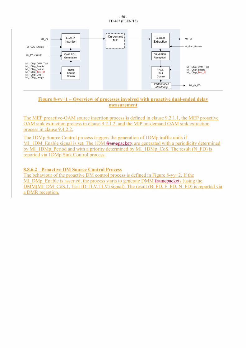
Figure 8-yy+1 – Overview of processes involved with proactive dual-ended delay
measurement
The MEP proactive-OAM source insertion process is defined in clause 9.2.1.1, the MEP proactive
OAM sink extraction process in clause 9.2.1.2, and the MIP on-demand OAM sink extraction
process in clause 9.4.2.2.
The 1DMp Source Control process triggers the generation of 1DMp traffic units if
MI_1DM_Enable signal is set. The 1DM framepackets are generated with a periodicity determined
by MI_1DMp_Period and with a priority determined by MI_1DMp_CoS. The result (N_FD) is
reported via 1DMp Sink Control process.
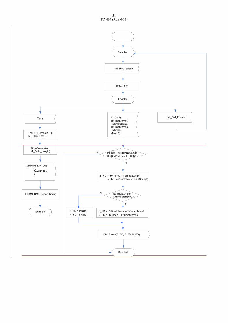
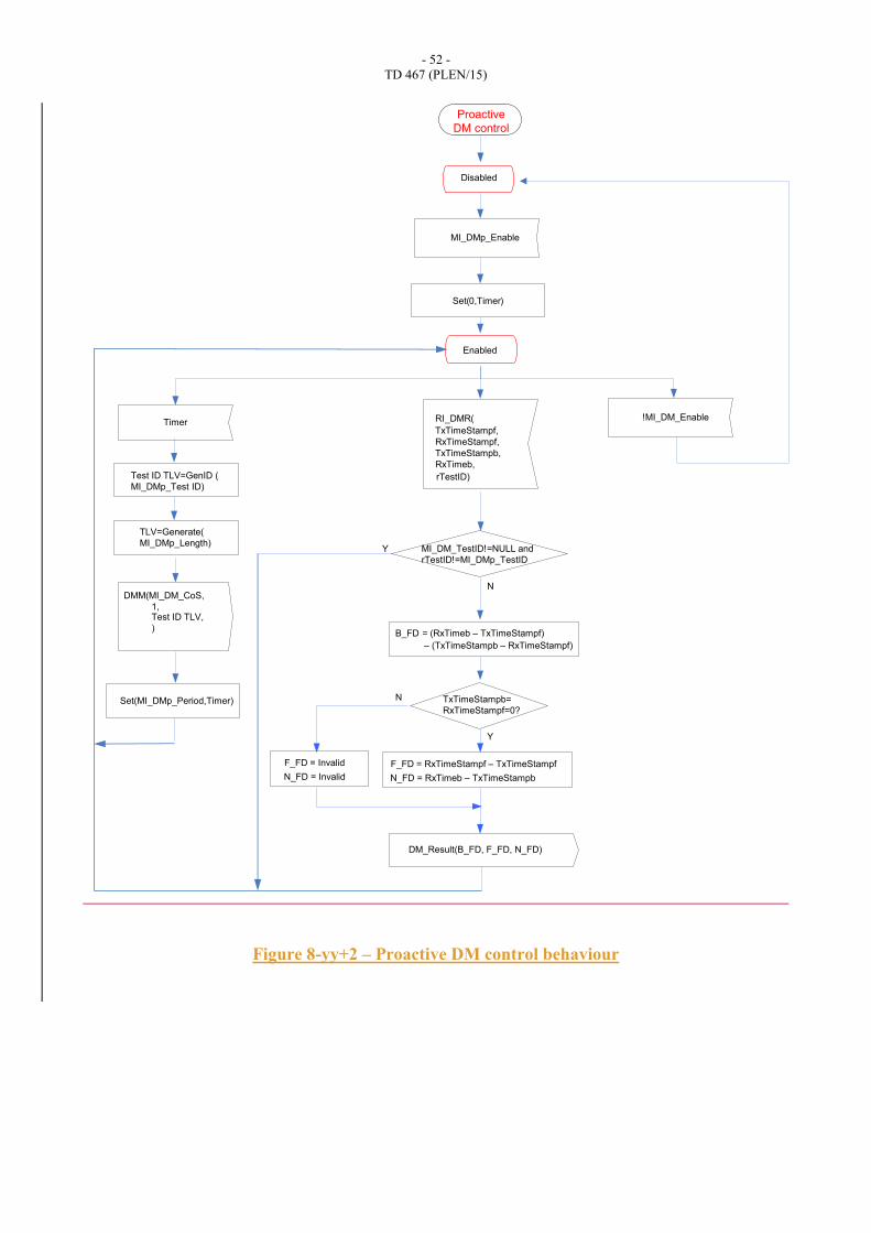
8.8.6.2 Proactive DM Source Control Process
The behaviour of the proactive DM control process is defined in Figure 8-yy+2. If the
MI_DMp_Enable is asserted, the process starts to generate DMM framepackets (using the
DMM(MI_DM_CoS,1, Test ID TLV,TLV) signal). The result (B_FD, F_FD, N_FD) is reported via
a DMR reception.
G-ACh
Insertion
OAM PDU
Generation
1DMp
Source
Control
MI_GAL_Enable
MI_TTLVALUE
MT_CIG-ACh
Extraction
OAM PDU
Reception
MT_CIOn-demand
MIP
1DMp
Sink
Control
MI_GAL_Enable
MI_1DMp_OAM_Tool
MI_1DMp_Enable
MI_1DMp_Test_ID
MI_1DMp_OAM_Tool
MI_1DMp_Enable
MI_1DMp_Period
MI_1DMp_Test_ID
MI_1DMp_CoS
MI_1DMp_Length
Performance
MonitoringMI_pN_FD
- 51 -
TD 467 (PLEN/15)
Disabled
MI_DMp_Enable
Enabled
Timer
DMM(MI_DM_CoS,
B_FD = (RxTimeb – TxTimeStampf)
Set(0,Timer)
Set(MI_DMp_Period,Timer)
DM_Result(B_FD, F_FD, N_FD)
– (TxTimeStampb – RxTimeStampf)
F_FD = RxTimeStampf – TxTimeStampf
N_FD = RxTimeb – TxTimeStampb
Y
N TxTimeStampb=
RxTimeStampf=0?
F_FD = Invalid
N_FD = Invalid
!MI_DM_Enable
TLV=Generate(
MI_DMp_Length)
1,Test ID TLV,
)
N
Y MI_DM_TestID!=NULL and
rTestID!=MI_DMp_TestID
RI_DMR(
TxTimeStampf,
RxTimeStampf,
TxTimeStampb,
RxTimeb,
rTestID)Test ID TLV=GenID (
MI_DMp_Test ID)
Enabled
Enabled
- 52 -
TD 467 (PLEN/15)
Figure 8-yy+2 – Proactive DM control behaviour
Disabled
MI_DMp_Enable
Enabled
Timer
DMM(MI_DM_CoS,
B_FD = (RxTimeb – TxTimeStampf)
Set(0,Timer)
Set(MI_DMp_Period,Timer)
DM_Result(B_FD, F_FD, N_FD)
– (TxTimeStampb – RxTimeStampf)
F_FD = RxTimeStampf – TxTimeStampf
N_FD = RxTimeb – TxTimeStampb
Y
N TxTimeStampb=
RxTimeStampf=0?
F_FD = Invalid
N_FD = Invalid
!MI_DM_Enable
TLV=Generate(
MI_DMp_Length)
1,Test ID TLV,
)
N
Y MI_DM_TestID!=NULL and
rTestID!=MI_DMp_TestID
RI_DMR(
TxTimeStampf,
RxTimeStampf,
TxTimeStampb,
RxTimeb,
rTestID)Test ID TLV=GenID (
MI_DMp_Test ID)
Proactive
DM control
- 53 -
TD 467 (PLEN/15)
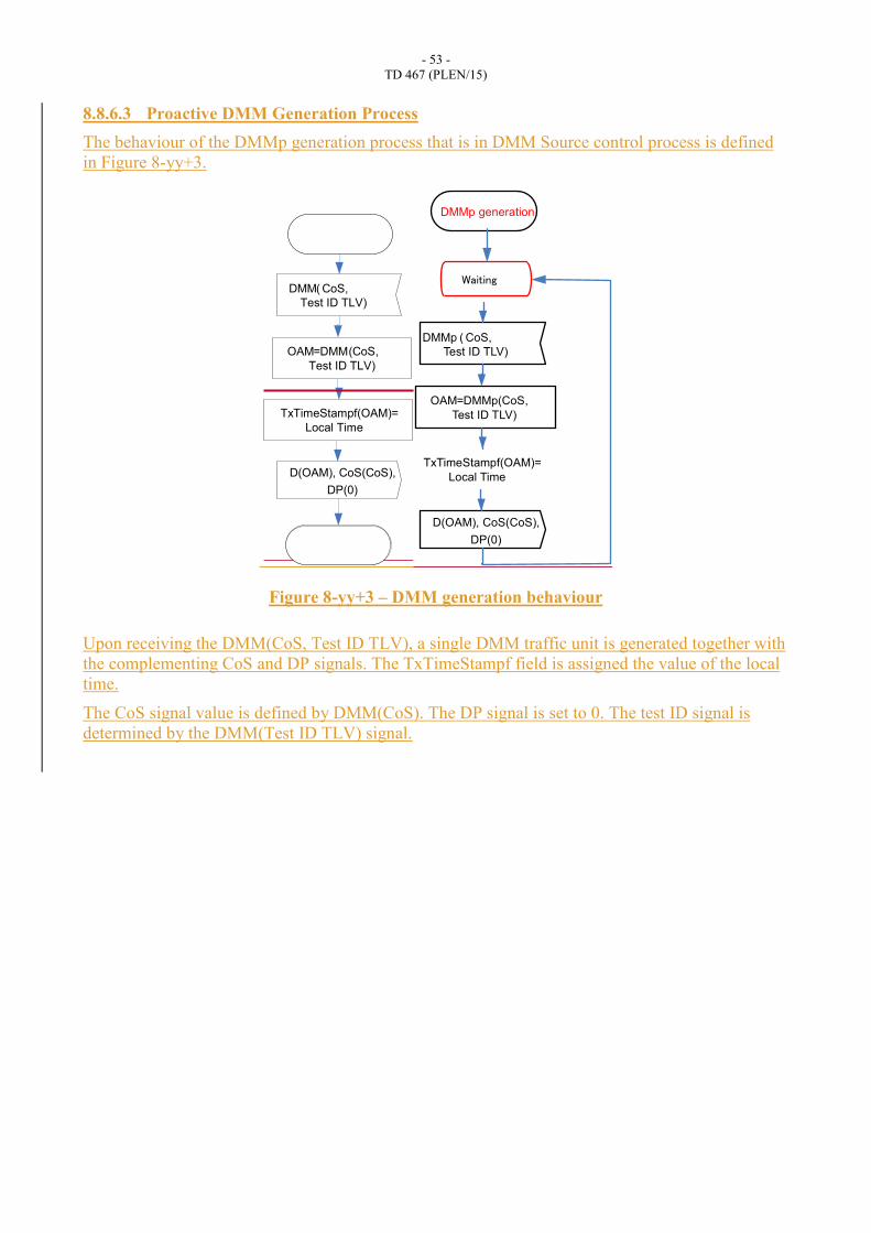
8.8.6.3 Proactive DMM Generation Process
The behaviour of the DMMp generation process that is in DMM Source control process is defined
in Figure 8-yy+3.
Figure 8-yy+3 – DMM generation behaviour
Upon receiving the DMM(CoS, Test ID TLV), a single DMM traffic unit is generated together with
the complementing CoS and DP signals. The TxTimeStampf field is assigned the value of the local
time.
The CoS signal value is defined by DMM(CoS). The DP signal is set to 0. The test ID signal is
determined by the DMM(Test ID TLV) signal.
DMM( CoS,
OAM=DMM(CoS,
Test ID TLV)
D(OAM), CoS(CoS),
TxTimeStampf(OAM)=
Local Time
Test ID TLV)
DP(0)
DMMp ( CoS,
OAM = DMMp (CoS, Test ID TLV)
D(OAM), CoS(CoS),
TxTimeStampf(OAM)= Local Time
Test ID TLV)
DP(0)
DMMp generation
Waiting
- 54 -
TD 467 (PLEN/15)
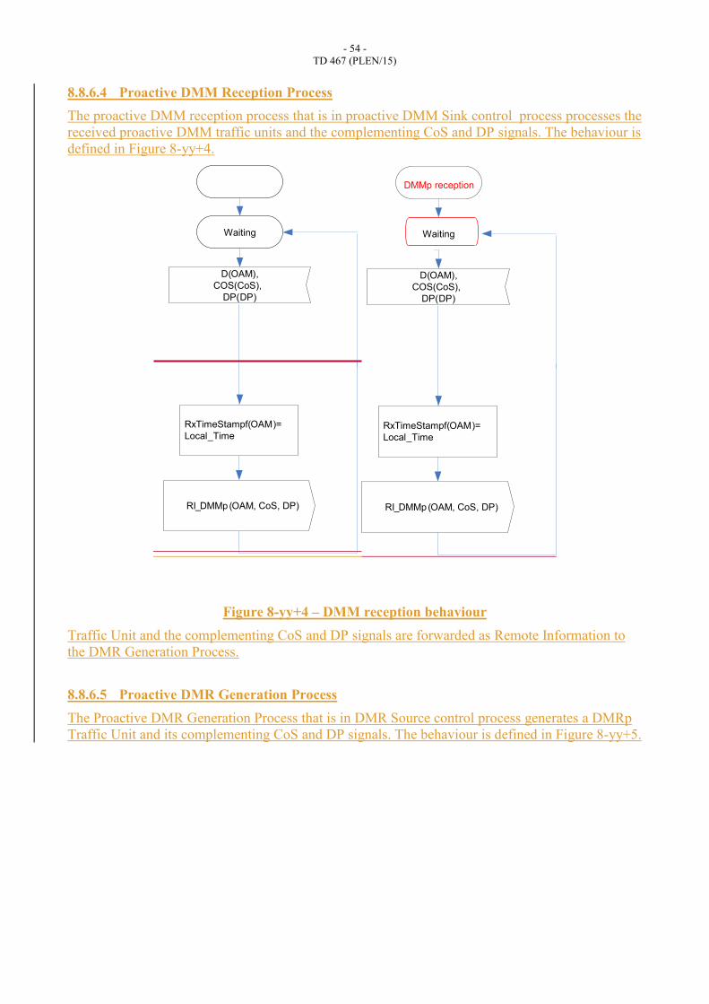
8.8.6.4 Proactive DMM Reception Process
The proactive DMM reception process that is in proactive DMM Sink control process processes the
received proactive DMM traffic units and the complementing CoS and DP signals. The behaviour is
defined in Figure 8-yy+4.
Figure 8-yy+4 – DMM reception behaviour
Traffic Unit and the complementing CoS and DP signals are forwarded as Remote Information to
the DMR Generation Process.
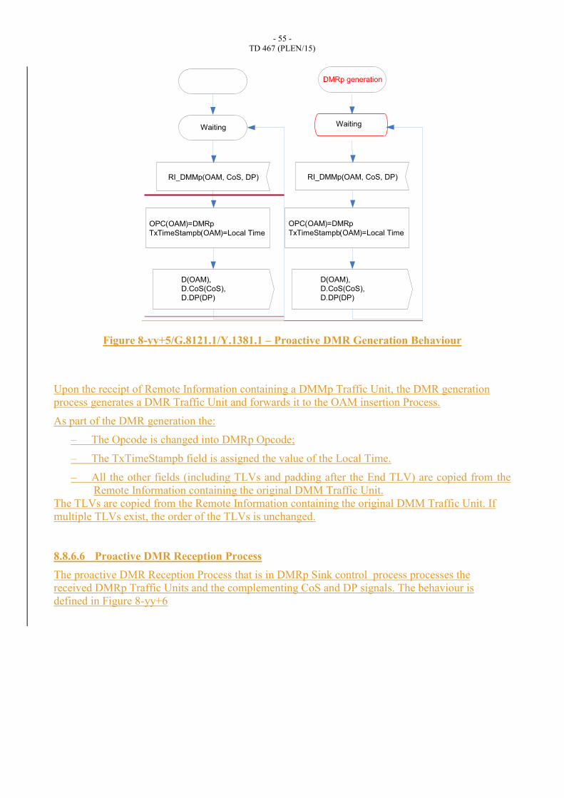
8.8.6.5 Proactive DMR Generation Process
The Proactive DMR Generation Process that is in DMR Source control process generates a DMRp
Traffic Unit and its complementing CoS and DP signals. The behaviour is defined in Figure 8-yy+5.
D(OAM),
COS(CoS),
DP(DP)
RI_DMMp(OAM, CoS, DP)
RxTimeStampf(OAM)=
Local_Time
Waiting
D(OAM),
COS(CoS),
DP(DP)
RI_DMMp(OAM, CoS, DP)
RxTimeStampf(OAM)=
Local_Time
Waiting
DMMp reception
- 55 -
TD 467 (PLEN/15)
Figure 8-yy+5/G.8121.1/Y.1381.1 – Proactive DMR Generation Behaviour
Upon the receipt of Remote Information containing a DMMp Traffic Unit, the DMR generation
process generates a DMR Traffic Unit and forwards it to the OAM insertion Process.
As part of the DMR generation the:
– The Opcode is changed into DMRp Opcode;
– The TxTimeStampb field is assigned the value of the Local Time.
– All the other fields (including TLVs and padding after the End TLV) are copied from the
Remote Information containing the original DMM Traffic Unit.
The TLVs are copied from the Remote Information containing the original DMM Traffic Unit. If
multiple TLVs exist, the order of the TLVs is unchanged.
8.8.6.6 Proactive DMR Reception Process
The proactive DMR Reception Process that is in DMRp Sink control process processes the
received DMRp Traffic Units and the complementing CoS and DP signals. The behaviour is
defined in Figure 8-yy+6
Waiting
RI_DMMp(OAM, CoS, DP)
OPC(OAM)=DMRp
TxTimeStampb(OAM)=Local Time
D(OAM),
D.CoS(CoS),
D.DP(DP)
RI_DMMp(OAM, CoS, DP)
OPC(OAM)=DMRp
TxTimeStampb(OAM)=Local Time
D(OAM),
D.CoS(CoS),
D.DP(DP)
Waiting
DMRp generation
- 56 -
TD 467 (PLEN/15)
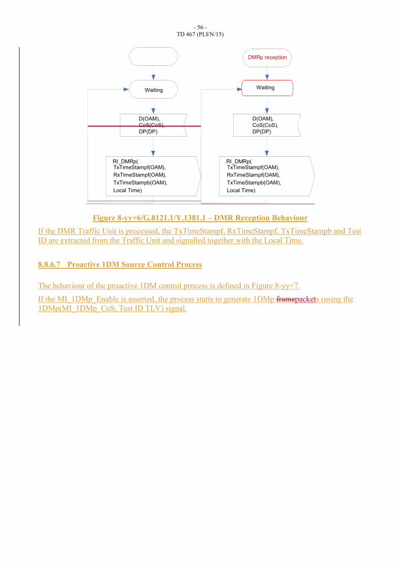
Figure 8-yy+6/G.8121.1/Y.1381.1 – DMR Reception Behaviour
If the DMR Traffic Unit is processed, the TxTimeStampf, RxTimeStampf, TxTimeStampb and Test
ID are extracted from the Traffic Unit and signalled together with the Local Time.
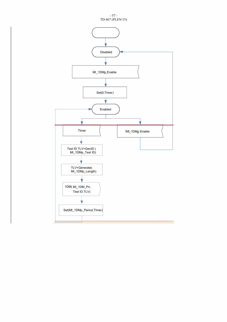
8.8.6.7 Proactive 1DM Source Control Process
The behaviour of the proactive 1DM control process is defined in Figure 8-yy+7.
If the MI_1DMp_Enable is asserted, the process starts to generate 1DMp framepackets (using the
1DMp(MI_1DMp_CoS, Test ID TLV) signal.
RI_DMRp(TxTimeStampf(OAM),
Local Time)
Waiting
RxTimeStampf(OAM),
TxTimeStampb(OAM),
D(OAM),
CoS(CoS),
DP(DP)
RI_DMRp(TxTimeStampf(OAM),
Local Time)
RxTimeStampf(OAM),
TxTimeStampb(OAM),
D(OAM),
CoS(CoS),
DP(DP)
Waiting
DMRp reception
- 57 -
TD 467 (PLEN/15)
Init
MI_1DM _Start(DA
MI_1DM_ Terminate
Running
Timer
Set(0,Timer)
Disabled
MI_1DMp_Enable
!MI_1DMp_ Enable
Enabled
Timer
Set(0,Timer)
TLV=Generate(
MI_1DMp_Length)
1DM(
Set(MI_1DMp_Period,Timer)
MI_1DM_Pri,
Test ID TLV)
Test ID TLV=GenID (
MI_1DMp_Test ID)
- 58 -
TD 467 (PLEN/15)
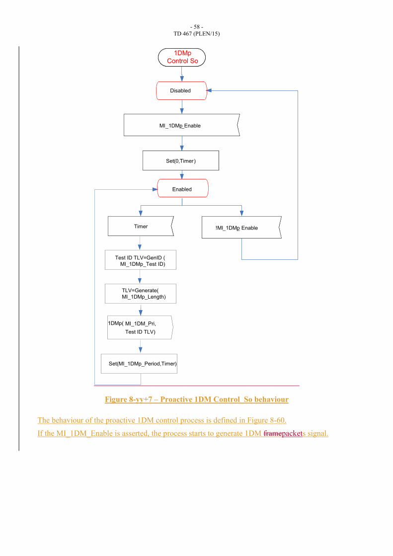
Figure 8-yy+7 – Proactive 1DM Control_So behaviour
The behaviour of the proactive 1DM control process is defined in Figure 8-60.
If the MI_1DM_Enable is asserted, the process starts to generate 1DM framepackets signal.
MI_1DM _Start(DA
MI_1DM_ TerminateTimer
Set(0,Timer)
Disabled
MI_1DMp_Enable
!MI_1DMp_ Enable
Enabled
Timer
Set(0,Timer)
TLV=Generate(
MI_1DMp_Length)
1DMp(
Set(MI_1DMp_Period,Timer)
MI_1DM_Pri,
Test ID TLV)
Test ID TLV=GenID (
MI_1DMp_Test ID)
1DMp
Control So

- 59 -
TD 467 (PLEN/15)
8.8.6.8 Proactive 1DM Generation Process
Figure 8-yy+8/G.8121.1/Y.1381.1 – 1DM Generation Behaviour
Figure 8-yy+8 shows the proactive 1DM Generation Process in 1DM Source control process. Upon
receiving the 1DMp(CoS) signal a single 1DM Traffic Unit is generated by the OAM=1DM (CoS,
LocalTime,) call.
Together with this 1DMp Traffic Unit the complementing CoS and DP signals are generated. The
TxTimeStampf field is assigned the value of the Local Time. The value of the CoS signal is
determined by the 1DMp(CoS) signal. The DP signal is set to 0.
8.8.6.9 Proactive 1DM Reception Process
The proactive 1DM Reception Process in 1DM Sink control process processes the received 1DMp
Traffic Units and the complementing P and CoS signals. The behaviour is defined in Figure 8-yy+9.
Waiting
1DMp
(CoS)
OAM=1DMp
(CoS,
LocalTime,)
D(OAM), CoS(CoS)
DP(0)
Waiting
1DMp
(CoS)
OAM=1DMp
(CoS,
LocalTime,)
D(OAM), CoS(CoS)
DP(0)
1DMp generation
- 60 -
TD 467 (PLEN/15)
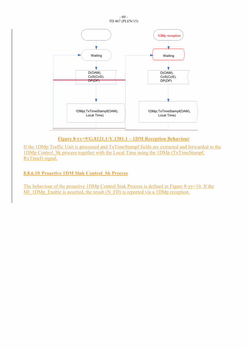
Figure 8-yy+9/G.8121.1/Y.1381.1 – 1DM Reception Behaviour
If the 1DMp Traffic Unit is processed and TxTimeStampf fields are extracted and forwarded to the
1DMp Control_Sk process together with the Local Time using the 1DMp (TxTimeStampf,
RxTimef) signal.
8.8.6.10 Proactive 1DM Sink Control_Sk Process
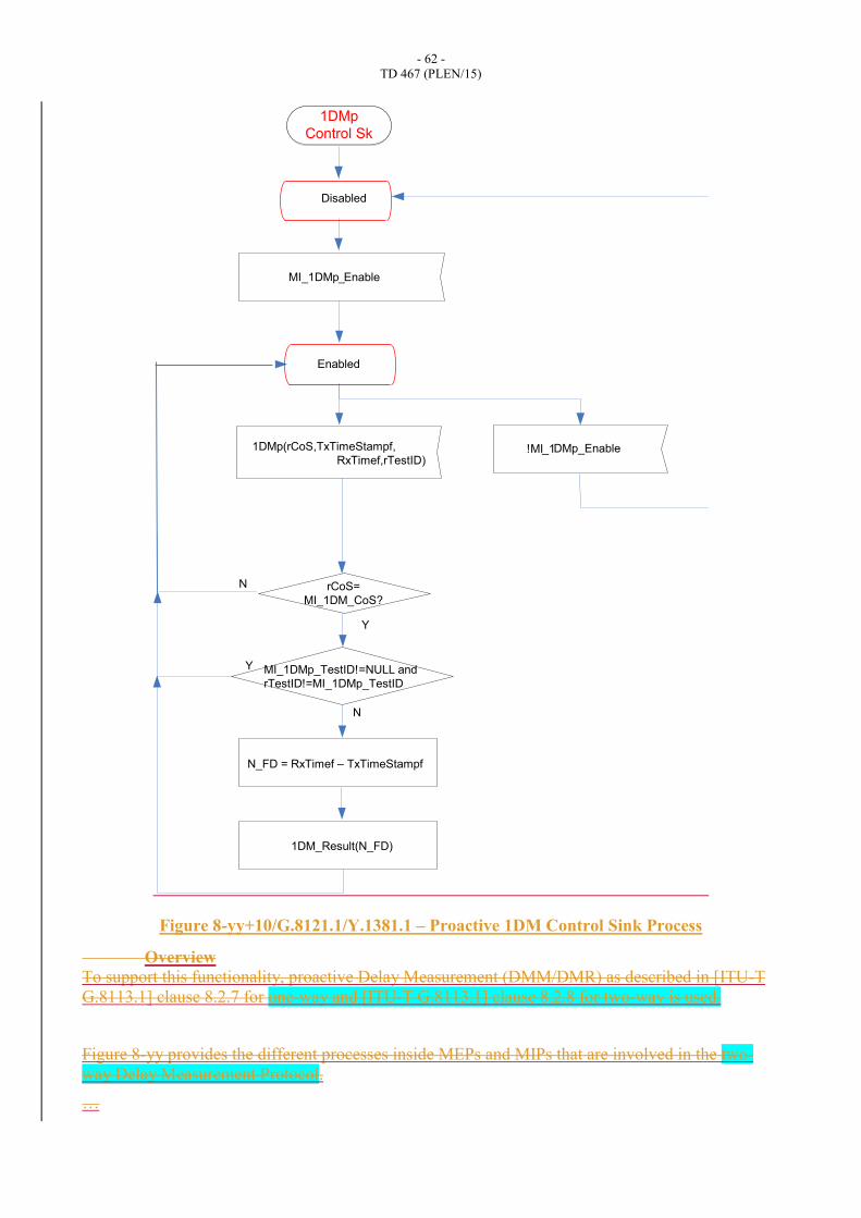
The behaviour of the proactive 1DMp Control Sink Process is defined in Figure 8-yy+10. If the
MI_1DMp_Enable is asserted, the result (N_FD) is reported via a 1DMp reception.
1DMp(TxTimeStampf(OAM),
Local Time)
Waiting
D(OAM),
CoS(CoS),
DP(DP)
1DMp(TxTimeStampf(OAM),
Local Time)
Waiting
D(OAM),
CoS(CoS),
DP(DP)
1DMp reception

- 61 -
TD 467 (PLEN/15)
Disabled
MI_1DMp_Enable
!MI_1DMp_Enable
Enabled
N_FD = RxTimef – TxTimeStampf
1DM_Result(N_FD)
N
Y MI_1DMp_TestID!=NULL and
rTestID!=MI_1DMp_TestID
1DMp(rCoS,TxTimeStampf,
RxTimef,rTestID)
rCoS=
MI_1DM_CoS?
Y
N
- 62 -
TD 467 (PLEN/15)
Figure 8-yy+10/G.8121.1/Y.1381.1 – Proactive 1DM Control Sink Process
Overview
To support this functionality, proactive Delay Measurement (DMM/DMR) as described in [ITU-T
G.8113.1] clause 8.2.7 for one-way and [ITU-T G.8113.1] clause 8.2.8 for two-way is used.
Figure 8-yy provides the different processes inside MEPs and MIPs that are involved in the two-
way Delay Measurement Protocol.
…
Disabled
MI_1DMp_Enable
!MI_1DMp_Enable
Enabled
N_FD = RxTimef – TxTimeStampf
1DM_Result(N_FD)
N
Y MI_1DMp_TestID!=NULL and
rTestID!=MI_1DMp_TestID
1DMp(rCoS,TxTimeStampf,
RxTimef,rTestID)
rCoS=
MI_1DM_CoS?
Y
N
1DMp
Control Sk

- 63 -
TD 467 (PLEN/15)
Figure 8-zz provides the different processes inside MEPs and MIPs that are involved in the One
Way Delay Measurement Protocol.
…
Proactive DM Source Control Process
Proactive DMM Generation Process
Proactive DMM Reception Process
Proactive DMR Generation Process
Proactive DMR Reception Process
Proactive 1DM Source Control Process
Proactive 1DM Generation Process
Proactive 1DM Reception Process
Proactive 1DM Sink Control_Sk Process
8.8.7 On-Demand Packet Delay Measurement (DMo)
On-demand Packet Delay Measurement (DMo)
8.8.6.18.8.7.1 Overview
To support this functionality, on-demand Delay Measurement (DMM/DMR) as described in [ITU-T
G.8113.1] clause 8.2.7 for dual-endedone-way and [ITU-T G.8113.1] clause 8.2.8 for single-
endedtwo-way is used.
Figure 8-20 provides the different processes inside MEPs and MIPs that are involved in the single-
endedtwo-way Delay Measurement Protocol.
The MEP On-Demand-OAM Source insertion process is defined in clause 9.2, the MEP On-
Demand OAM Sink extraction process in clause 9.2, the MIP On-Demand OAM Sink Extraction
process in clause 9.4, and the MIP On-Demand OAM Source insertion process in clause 9.4. In
summary, they insert and extract MT_CI OAM signals into and from the stream of MT_C_D
Traffic Units and the complementing PHB signals going through an MEP and MIP;
- 64 -
TD 467 (PLEN/15)
G-ACh
Insertion
OAM PDU
Generation
DMMo
Source
Control
MI_GAL_Enable
MI_TTLVALUE
DMRo
Sink
Control
OAM PDU
Reception
G-ACh
Extraction
MI_GAL_Enable
MT_CI
MT_CI
G-ACh
Extraction
OAM PDU
Reception
OAM PDU
Generation
G-ACh
Extraction
MT_CI
On-demand
MIP
On-demand
MIP
DMRo
Source
Control
RI_DMMo(D, CoS, DP)
DMMo
Sink
Control
MI_GAL_Enable
MI_GAL_Enable
MI_TTLVALUE
MI_DMo_Result
(count,B_FD[],F_FD[],N_FD[])
MI_DMo_Start
(CoS,Period)
MI_DMo_TerminateMI_DMo_CoS
MI_DMo_OAM_Tool
RI_DMRo(TxTimeStampf,RxTimeStampf,
TxTimeStampb,RxTimeb,CoS)
MT_CI
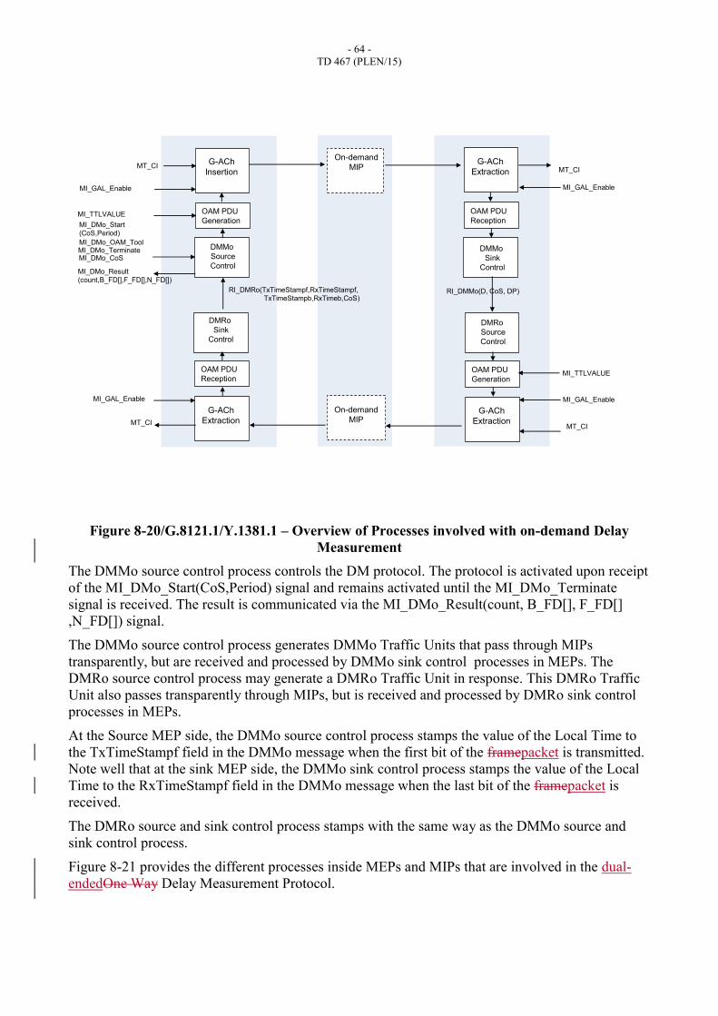
Figure 8-20/G.8121.1/Y.1381.1 – Overview of Processes involved with on-demand Delay
Measurement
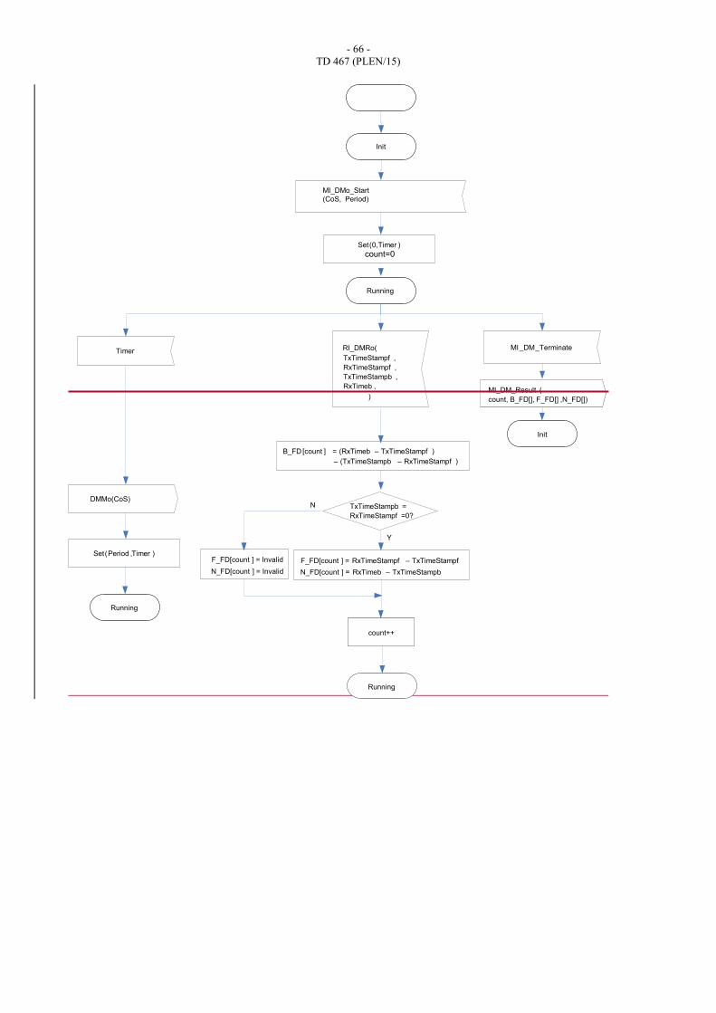
The DMMo source control process controls the DM protocol. The protocol is activated upon receipt
of the MI_DMo_Start(CoS,Period) signal and remains activated until the MI_DMo_Terminate
signal is received. The result is communicated via the MI_DMo_Result(count, B_FD[], F_FD[]
,N_FD[]) signal.
The DMMo source control process generates DMMo Traffic Units that pass through MIPs
transparently, but are received and processed by DMMo sink control processes in MEPs. The
DMRo source control process may generate a DMRo Traffic Unit in response. This DMRo Traffic
Unit also passes transparently through MIPs, but is received and processed by DMRo sink control
processes in MEPs.
At the Source MEP side, the DMMo source control process stamps the value of the Local Time to
the TxTimeStampf field in the DMMo message when the first bit of the framepacket is transmitted.
Note well that at the sink MEP side, the DMMo sink control process stamps the value of the Local
Time to the RxTimeStampf field in the DMMo message when the last bit of the framepacket is
received.
The DMRo source and sink control process stamps with the same way as the DMMo source and
sink control process.
Figure 8-21 provides the different processes inside MEPs and MIPs that are involved in the dual-
endedOne Way Delay Measurement Protocol.
- 65 -
TD 467 (PLEN/15)
The MEP On-Demand OAM Source insertion process is defined in clause 9.2, the MEP On-
Demand-OAM Sink extraction process in clause 9.2, the MIP On-Demand OAM Sink Extraction
process in clause 9.4, and the MIP On-Demand OAM Source insertion process in clause 9.4. In
summary, they insert and extract MT_CI OAM signals into and from the stream of MT_CI_D
Traffic Units and the complementing PHB signals going through an MEP and MIP.
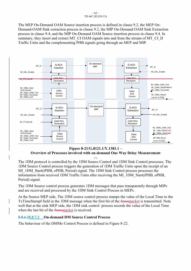
Figure 8-21/G.8121.1/Y.1381.1 –
Overview of Processes involved with on-demand One Way Delay Measurement
, ,
The 1DM protocol is controlled by the 1DM Source Control and 1DM Sink Control processes. The
1DM Source Control process triggers the generation of 1DM Traffic Units upon the receipt of an
MI_1DM_Start(iPHB, oPHB, Period) signal. The 1DM Sink Control process processes the
information from received 1DM Traffic Units after receiving the MI_1DM_Start(iPHB, oPHB,
Period) signal.
The 1DM Source control process generates 1DM messages that pass transparently through MIPs
and are received and processed by the 1DM Sink Control Process in MEPs.
At the Source MEP side, The 1DM source control process stamps the value of the Local Time to the
TxTimeStampf field in the 1DM message when the first bit of the framepacket is transmitted. Note
well that at the sink MEP side, the 1DM sink control process records the value of the Local Time
when the last bit of the framepacket is received.
8.8.6.28.8.7.2 On-demand DM Source Control Process
The behaviour of the DMMo Control Process is defined in Figure 8-22.
G-ACh
Insertion
OAM PDU
Generation
1DMo
Source
Control
MI_GAL_Enable
MI_TTLVALUE
MT_CIG-ACh
Extraction
OAM PDU
Reception
MT_CI
On-demand
MIP
1DMo
Sink
Control
MI_GAL_Enable
MI_1DMo_Start
(CoS,Period)
MI_1DMo_TerminateMI_1DMo_CoS
MI_1DMo_OAM_Tool
MI_1DMo_Start(Pattern)
MI_1DMo_Result
(count, N_FD[])
MI_1DMo_Terminate
MI_1DMo_OAM_Tool
G-ACh Insertion
OAM PDU Generation
1DMo Source
Control
MI_GAL_Enable
MI_TTLVALUE
MT_CI G-ACh
Extraction
OAM PDU Reception
MT_CI
On-demand
MIP
1DMo Sink
Control
MI_GAL_Enable
MI_1DMo_Start (CoS,Period)
MI_1DMo_Terminate MI_1DMo_CoS
MI_1DMo_OAM_Tool
MI _ 1 DM o_Start(CoS)
MI_1DMo_Result (count, N_FD[])
MI_1DMo_Terminate
MI_1DMo_OAM_Tool
- 66 -
TD 467 (PLEN/15)
Init
MI_DM_Terminate
Running
Timer
DMMo(CoS)
Running
TxTimeStampf ,
RxTimeStampf ,
TxTimeStampb ,
RxTimeb ,
)
B_FD [count ] = (RxTimeb – TxTimeStampf )
Init
Running
Set(0,Timer )
Set(Period ,Timer )
– (TxTimeStampb – RxTimeStampf )
MI_DM_Result (
count, B_FD[], F_FD[] ,N_FD[])
F_FD[count ] = RxTimeStampf – TxTimeStampf
N_FD[count ] = RxTimeb – TxTimeStampb
Y
N TxTimeStampb =
RxTimeStampf =0?
F_FD[count ] = Invalid
N_FD[count ] = Invalid
count=0
count++
MI_DMo_Start
(CoS, Period)
RI_DMRo(
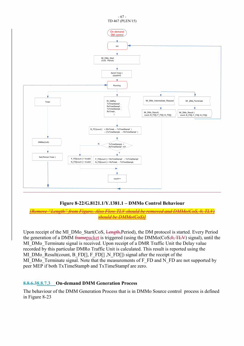
- 67 -
TD 467 (PLEN/15)
Figure 8-22/G.8121.1/Y.1381.1 – DMMo Control Behaviour
[Remove “Length” from Figure, Also Flow TLV should be removed and DMMo(CoS, 0, TLV)
should be DMMo(CoS)]
Upon receipt of the MI_DMo_Start(CoS, Length,Period), the DM protocol is started. Every Period
the generation of a DMM framepacket is triggered (using the DMMo(CoS,0, TLV) signal), until the
MI_DMo_Terminate signal is received. Upon receipt of a DMR Traffic Unit the Delay value
recorded by this particular DMRo Traffic Unit is calculated. This result is reported using the
MI_DMo_Result(count, B_FD[], F_FD[] ,N_FD[]) signal after the receipt of the
MI_DMo_Terminate signal. Note that the measurements of F_FD and N_FD are not supported by
peer MEP if both TxTimeStampb and TxTimeStampf are zero.
8.8.6.38.8.7.3 On-demand DMM Generation Process
The behaviour of the DMM Generation Process that is in DMMo Source control process is defined
in Figure 8-23
Init
MI _DMo_Terminate
Running
Timer
DMMo(CoS)
TxTimeStampf ,
RxTimeStampf ,
TxTimeStampb ,
RxTimeb ,
)
B_FD [count ] = (RxTimeb – TxTimeStampf )
Set(0,Timer )
Set(Period ,Timer )
– (TxTimeStampb – RxTimeStampf )
MI_DMo_Result (
count, B_FD[], F_FD[] ,N_FD[])
F_FD[count ] = RxTimeStampf – TxTimeStampf
N_FD[count ] = RxTimeb – TxTimeStampb
Y
N TxTimeStampb =
RxTimeStampf =0?
F_FD[count ] = Invalid
N_FD[count ] = Invalid
count=0
count++
MI_DMo_Start
(CoS, Period)
RI_DMRo(
On-demand
DM control
MI_DMo_Result (
count, B_FD[], F_FD[] ,N_FD[])
MI_DMo_Intermediate_Request
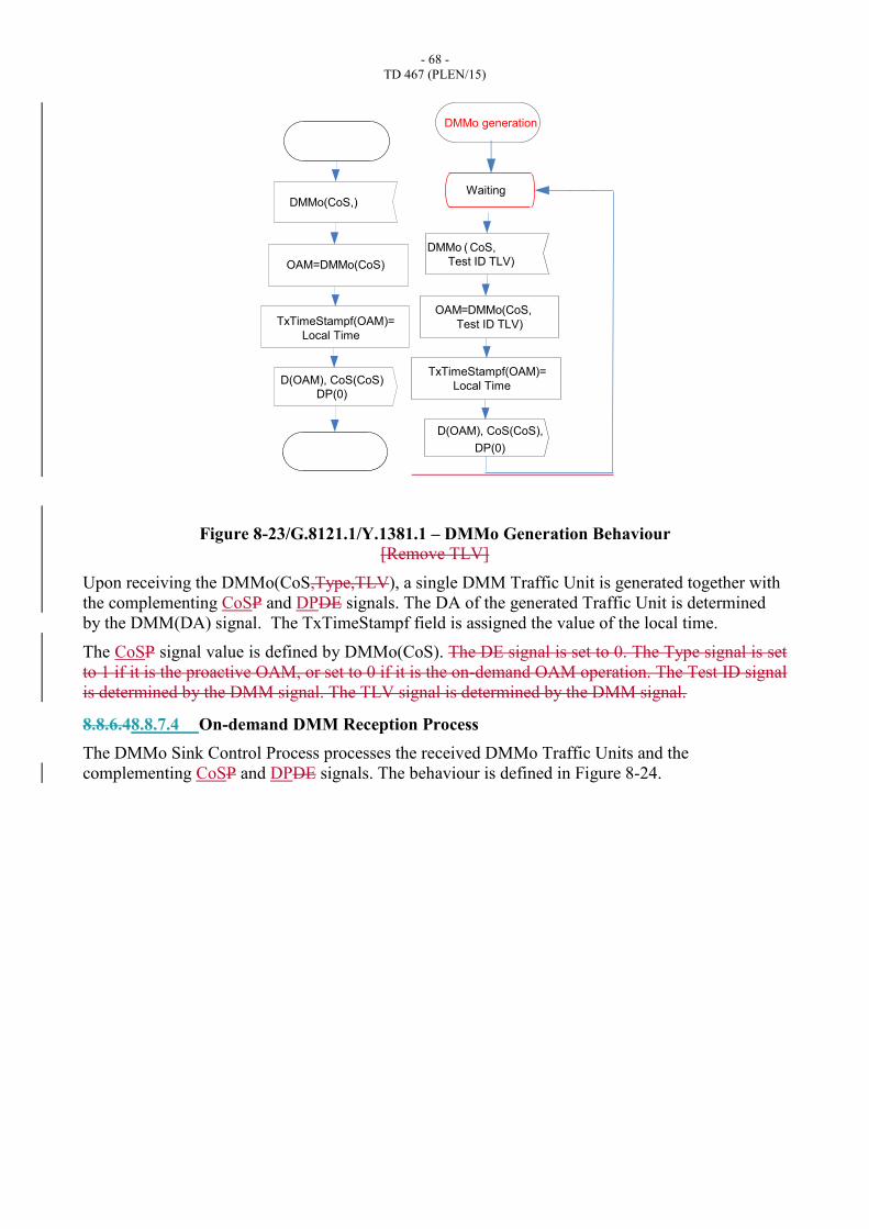
- 68 -
TD 467 (PLEN/15)
Figure 8-23/G.8121.1/Y.1381.1 – DMMo Generation Behaviour
[Remove TLV]
Upon receiving the DMMo(CoS,Type,TLV), a single DMM Traffic Unit is generated together with
the complementing CoSP and DPDE signals. The DA of the generated Traffic Unit is determined
by the DMM(DA) signal. The TxTimeStampf field is assigned the value of the local time.
The CoSP signal value is defined by DMMo(CoS). The DE signal is set to 0. The Type signal is set
to 1 if it is the proactive OAM, or set to 0 if it is the on-demand OAM operation. The Test ID signal
is determined by the DMM signal. The TLV signal is determined by the DMM signal.
8.8.6.48.8.7.4 On-demand DMM Reception Process
The DMMo Sink Control Process processes the received DMMo Traffic Units and the
complementing CoSP and DPDE signals. The behaviour is defined in Figure 8-24.
DMMo(CoS,)
OAM=DMMo(CoS)
D(OAM), CoS(CoS)
DP(0)
TxTimeStampf(OAM)=
Local Time
DMMo ( CoS,
OAM=DMMo(CoS,
Test ID TLV)
D(OAM), CoS(CoS),
TxTimeStampf(OAM)=
Local Time
Test ID TLV)
DP(0)
DMMo generation
Waiting
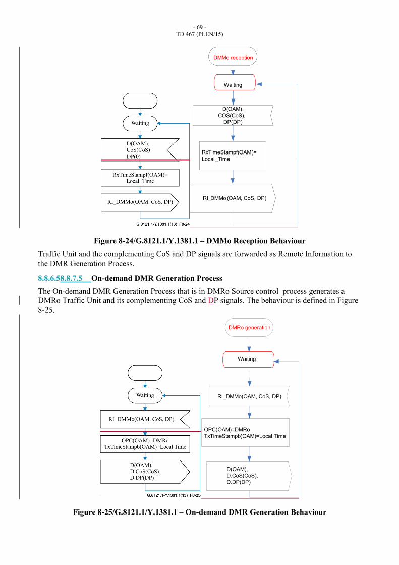
- 69 -
TD 467 (PLEN/15)
Figure 8-24/G.8121.1/Y.1381.1 – DMMo Reception Behaviour
Traffic Unit and the complementing CoS and DP signals are forwarded as Remote Information to
the DMR Generation Process.
8.8.6.58.8.7.5 On-demand DMR Generation Process
The On-demand DMR Generation Process that is in DMRo Source control process generates a
DMRo Traffic Unit and its complementing CoS and DP signals. The behaviour is defined in Figure
8-25.
Figure 8-25/G.8121.1/Y.1381.1 – On-demand DMR Generation Behaviour
D(OAM),
COS(CoS),
DP(DP)
RI_DMMo (OAM, CoS, DP)
RxTimeStampf(OAM)=
Local_Time
Waiting
DMMo reception
RI_DMMo(OAM, CoS, DP)
OPC(OAM)=DMRo
TxTimeStampb(OAM)=Local Time
D(OAM),
D.CoS(CoS),
D.DP(DP)
Waiting
DMRo generation
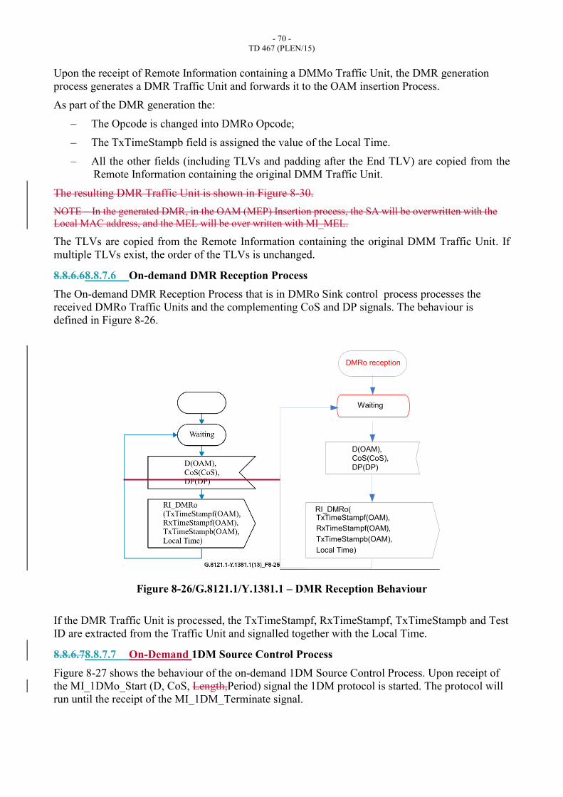
- 70 -
TD 467 (PLEN/15)
Upon the receipt of Remote Information containing a DMMo Traffic Unit, the DMR generation
process generates a DMR Traffic Unit and forwards it to the OAM insertion Process.
As part of the DMR generation the:
– The Opcode is changed into DMRo Opcode;
– The TxTimeStampb field is assigned the value of the Local Time.
– All the other fields (including TLVs and padding after the End TLV) are copied from the
Remote Information containing the original DMM Traffic Unit.
The resulting DMR Traffic Unit is shown in Figure 8-30.
NOTE – In the generated DMR, in the OAM (MEP) Insertion process, the SA will be overwritten with the
Local MAC address, and the MEL will be over written with MI_MEL.
The TLVs are copied from the Remote Information containing the original DMM Traffic Unit. If
multiple TLVs exist, the order of the TLVs is unchanged.
8.8.6.68.8.7.6 On-demand DMR Reception Process
The On-demand DMR Reception Process that is in DMRo Sink control process processes the
received DMRo Traffic Units and the complementing CoS and DP signals. The behaviour is
defined in Figure 8-26.
Figure 8-26/G.8121.1/Y.1381.1 – DMR Reception Behaviour
If the DMR Traffic Unit is processed, the TxTimeStampf, RxTimeStampf, TxTimeStampb and Test
ID are extracted from the Traffic Unit and signalled together with the Local Time.
8.8.6.78.8.7.7 On-Demand 1DM Source Control Process
Figure 8-27 shows the behaviour of the on-demand 1DM Source Control Process. Upon receipt of
the MI_1DMo_Start (D, CoS, Length,Period) signal the 1DM protocol is started. The protocol will
run until the receipt of the MI_1DM_Terminate signal.
RI_DMRo(TxTimeStampf(OAM),
Local Time)
RxTimeStampf(OAM),
TxTimeStampb(OAM),
D(OAM),
CoS(CoS),
DP(DP)
Waiting
DMRo reception

- 71 -
TD 467 (PLEN/15)
If the On-demand DM protocol is running every Period (as specified in the MI_1DMo_Start signal)
the generation of a 1DMo message is triggered by generating the 1DMo(D, CoS,0, TLV) signal
towards the 1DMo Generation Process.
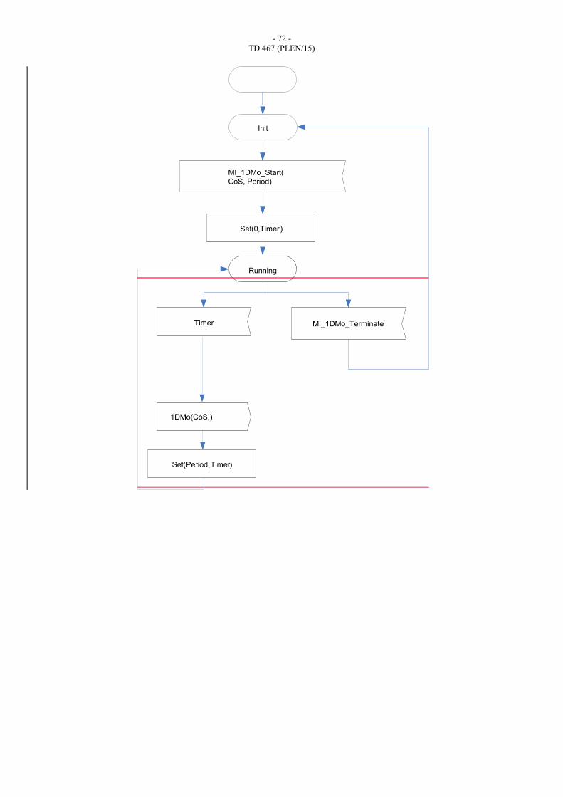
- 72 -
TD 467 (PLEN/15)
Init
MI_1DM_Start(DA
_Terminate
Running
Timer
1DM(DA,P)
Set(0,Timer)
Set(Period,Timer)
Init
MI_1DMo_Start(
CoS, Period)
Running
Timer
1DMo(CoS,),
Set(0,Timer)
Set(Period,Timer)
MI_1DMo_Terminate
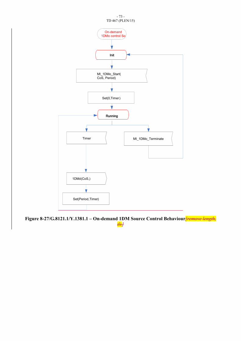
- 73 -
TD 467 (PLEN/15)
Figure 8-27/G.8121.1/Y.1381.1 – On-demand 1DM Source Control Behaviour[remove length,
tlv]
Init
MI_1DM_Start(DA
_Terminate
Running
Timer
1DM(DA,P)
Set(0,Timer)
Set(Period,Timer)
Init
MI_1DMo_Start(
CoS, Period)
Running
Timer
1DMo(CoS,),
Set(0,Timer)
Set(Period,Timer)
MI_1DMo_Terminate
On-demand
1DMo control So
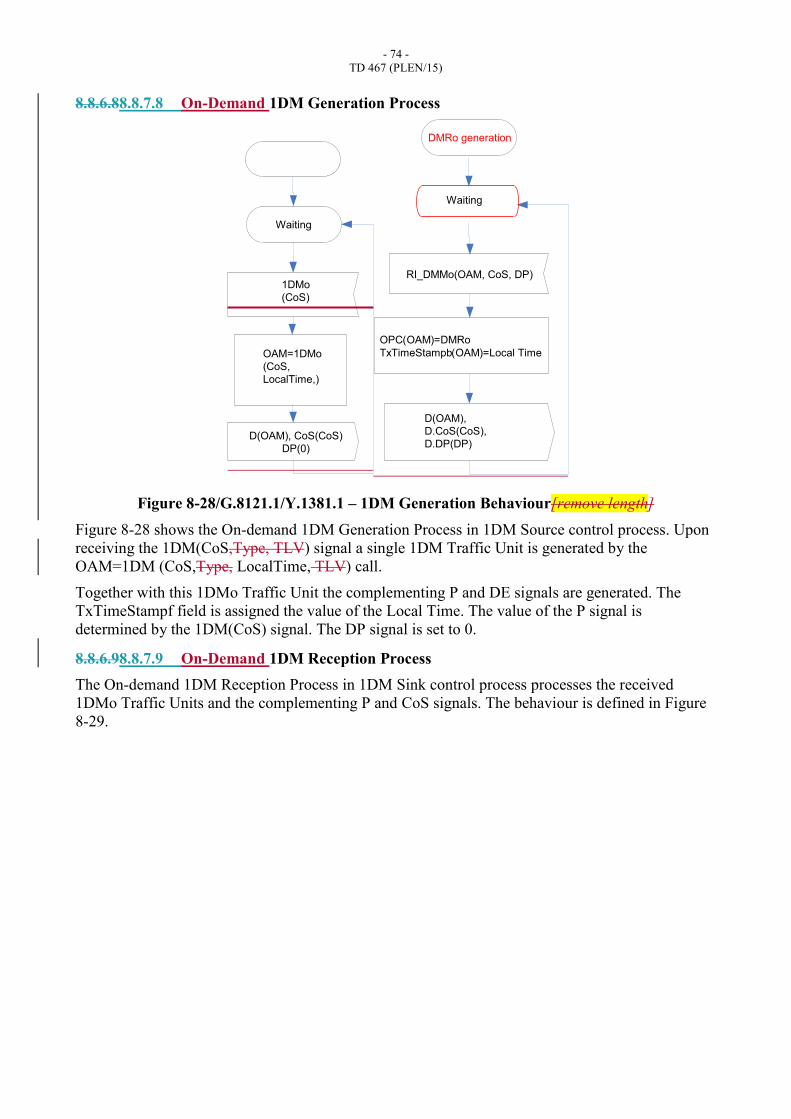
- 74 -
TD 467 (PLEN/15)
8.8.6.88.8.7.8 On-Demand 1DM Generation Process
Figure 8-28/G.8121.1/Y.1381.1 – 1DM Generation Behaviour[remove length]
Figure 8-28 shows the On-demand 1DM Generation Process in 1DM Source control process. Upon
receiving the 1DM(CoS,Type, TLV) signal a single 1DM Traffic Unit is generated by the
OAM=1DM (CoS,Type, LocalTime, TLV) call.
Together with this 1DMo Traffic Unit the complementing P and DE signals are generated. The
TxTimeStampf field is assigned the value of the Local Time. The value of the P signal is
determined by the 1DM(CoS) signal. The DP signal is set to 0.
8.8.6.98.8.7.9 On-Demand 1DM Reception Process
The On-demand 1DM Reception Process in 1DM Sink control process processes the received
1DMo Traffic Units and the complementing P and CoS signals. The behaviour is defined in Figure
8-29.
Waiting
1DMo
(CoS)
OAM=1DMo
(CoS,
LocalTime,)
D(OAM), CoS(CoS)
DP(0)
RI_DMMo(OAM, CoS, DP)
OPC(OAM)=DMRo
TxTimeStampb(OAM)=Local Time
D(OAM),
D.CoS(CoS),
D.DP(DP)
Waiting
DMRo generation
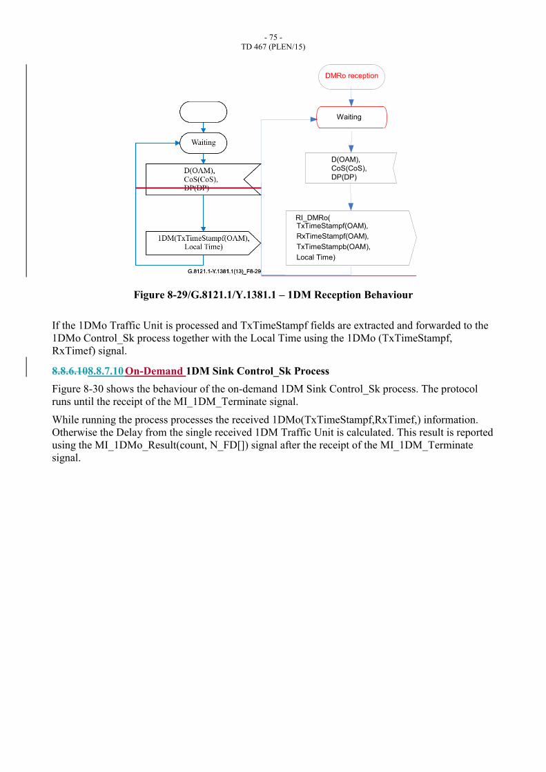
- 75 -
TD 467 (PLEN/15)
Figure 8-29/G.8121.1/Y.1381.1 – 1DM Reception Behaviour
If the 1DMo Traffic Unit is processed and TxTimeStampf fields are extracted and forwarded to the
1DMo Control_Sk process together with the Local Time using the 1DMo (TxTimeStampf,
RxTimef) signal.
8.8.6.108.8.7.10 On-Demand 1DM Sink Control_Sk Process
Figure 8-30 shows the behaviour of the on-demand 1DM Sink Control_Sk process. The protocol
runs until the receipt of the MI_1DM_Terminate signal.
While running the process processes the received 1DMo(TxTimeStampf,RxTimef,) information.
Otherwise the Delay from the single received 1DM Traffic Unit is calculated. This result is reported
using the MI_1DMo_Result(count, N_FD[]) signal after the receipt of the MI_1DM_Terminate
signal.
RI_DMRo(TxTimeStampf(OAM),
Local Time)
RxTimeStampf(OAM),
TxTimeStampb(OAM),
D(OAM),
CoS(CoS),
DP(DP)
Waiting
DMRo reception
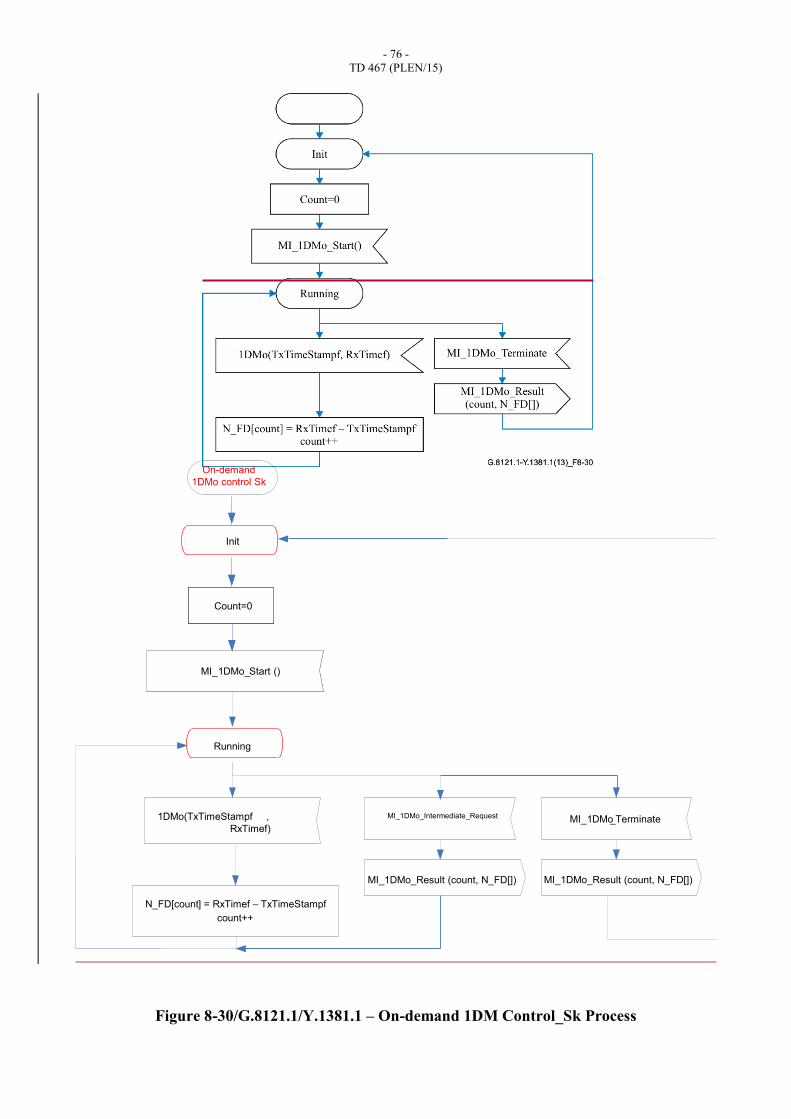
- 76 -
TD 467 (PLEN/15)
Figure 8-30/G.8121.1/Y.1381.1 – On-demand 1DM Control_Sk Process
Init
MI_1DMo_Start ()
MI_1DMo_Terminate
Running
1DMo(TxTimeStampf ,
RxTimef)
N_FD[count] = RxTimef – TxTimeStampf
Count=0Count=0
count++
MI_1DMo_Result (count, N_FD[])
On-demand
1DMo control Sk
MI_1DMo_Result (count, N_FD[])
MI_1DMo_Intermediate_Request
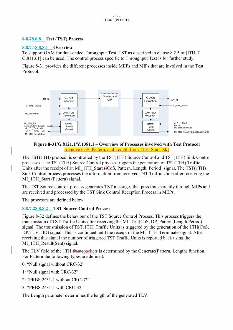
- 77 -
TD 467 (PLEN/15)
8.8.78.8.8 Test (TST) Process
8.8.7.18.8.8.1 Overview
To support OAM for dual-ended Throughput Test, TST as described in clause 8.2.5 of [ITU-T
G.8113.1] can be used. The control process specific to Throughput Test is for further study.
Figure 8-31 provides the different processes inside MEPs and MIPs that are involved in the Test
Protocol.
Figure 8-31/G.8121.1/Y.1381.1 – Overview of Processes involved with Test Protocol
[remove CoS, Pattern, and Length from 1TH_Start_Sk]
The TST(1TH) protocol is controlled by the TST(1TH) Source Control and TST(1TH) Sink Control
processes. The TST(1TH) Source Control process triggers the generation of TST(1TH) Traffic
Units after the receipt of an MI_1TH_Start (iCoS, Pattern, Length, Period) signal. The TST(1TH)
Sink Control process processes the information from received TST Traffic Units after receiving the
MI_1TH_Start (Pattern) signal.
The TST Source control process generates TST messages that pass transparently through MIPs and
are received and processed by the TST Sink Control Reception Process in MEPs.
The processes are defined below.
8.8.7.28.8.8.2 TST Source Control Process
Figure 8-32 defines the behaviour of the TST Source Control Process. This process triggers the
transmission of TST Traffic Units after receiving the MI_Test(CoS, DP, Pattern,Length,Period)
signal. The transmission of TST(1TH) Traffic Units is triggered by the generation of the 1TH(CoS,
DP,TLV,TID) signal. This is continued until the receipt of the MI_1TH_Terminate signal. After
receiving this signal the number of triggered TST Traffic Units is reported back using the
MI_1TH_Result(Sent) signal.
The TLV field of the 1TH framepackets is determined by the Generate(Pattern, Length) function.
For Pattern the following types are defined:
0: “Null signal without CRC-32”
1: “Null signal with CRC-32”
2: “PRBS 2^31-1 without CRC-32”
3: “PRBS 2^31-1 with CRC-32”
The Length parameter determines the length of the generated TLV.
G-ACh
Insertion
OAM PDU
Generation
DMMo
Source
Control
MI_GAL_Enable
MI_TTLVALUE
MT_CIG-ACh
Extraction
OAM PDU
Reception
MT_CI
On-demand
MIP
DMMo
Sink
Control
MI_GAL_Enable
MI_1TH_Start
(Period)
MI_1TH_Result(REC,CRC,BER,OO)
MI_1TH_Terminate
MI_1TH_Start
(CoS, Pattern, Length, Period)
MI_1TH_Result (Sent)
MI_1TH_OAM_Tool
MI_1TH_Terminate

- 78 -
TD 467 (PLEN/15)
Generate(Pattern, Length) generates a Test TLV with length ‘Length’ to be included in the 1TH
framepacket. Therefore, this TLV is passed using the 1TH(CoS,DP,TLV,TID) signal to the TST
Generation Process.

- 79 -
TD 467 (PLEN/15)
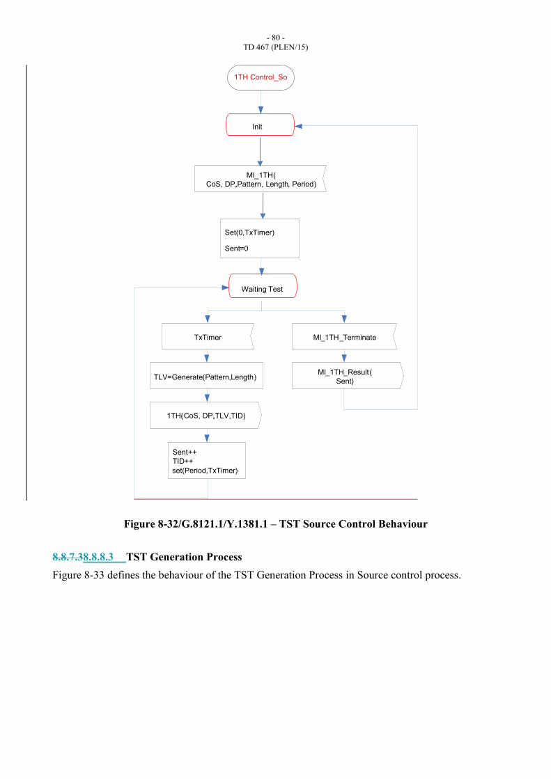
- 80 -
TD 467 (PLEN/15)
Figure 8-32/G.8121.1/Y.1381.1 – TST Source Control Behaviour
8.8.7.38.8.8.3 TST Generation Process
Figure 8-33 defines the behaviour of the TST Generation Process in Source control process.
Set(0,TxTimer)
Sent=0
Waiting Test
TxTimer
1TH( ,TLV,TID)
TLV=Generate(Pattern,Length)
MI_1TH_Terminate
MI_1TH_Result(
Sent)
Sent++
TID++
Init
MI_1TH(
CoS, DP,,Pattern, Length, Period)
set(Period,TxTimer)
CoS, DP,
1TH Control_So
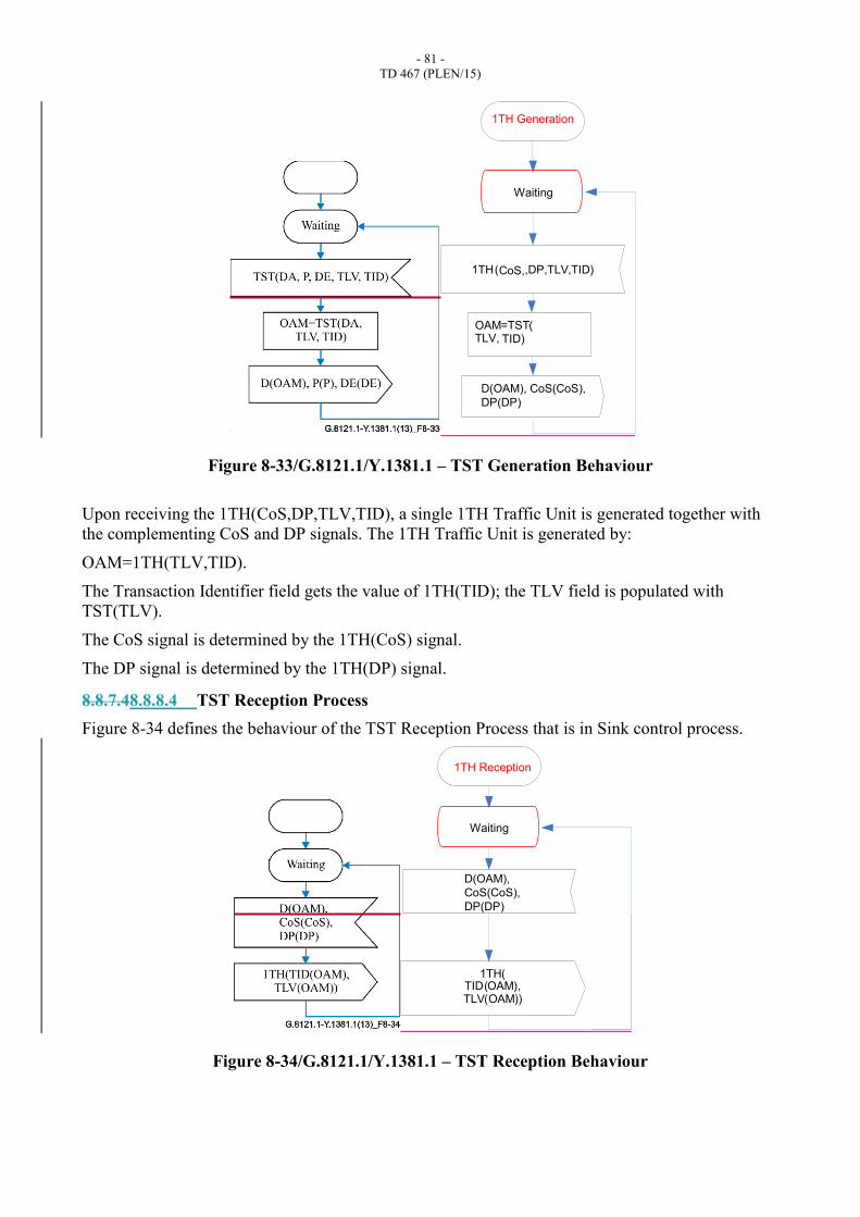
- 81 -
TD 467 (PLEN/15)
Figure 8-33/G.8121.1/Y.1381.1 – TST Generation Behaviour
Upon receiving the 1TH(CoS,DP,TLV,TID), a single 1TH Traffic Unit is generated together with
the complementing CoS and DP signals. The 1TH Traffic Unit is generated by:
OAM=1TH(TLV,TID).
The Transaction Identifier field gets the value of 1TH(TID); the TLV field is populated with
TST(TLV).
The CoS signal is determined by the 1TH(CoS) signal.
The DP signal is determined by the 1TH(DP) signal.
8.8.7.48.8.8.4 TST Reception Process
Figure 8-34 defines the behaviour of the TST Reception Process that is in Sink control process.
Figure 8-34/G.8121.1/Y.1381.1 – TST Reception Behaviour
1TH(CoS,,DP,TLV,TID)
Waiting
OAM=TST(TLV, TID)
D(OAM), CoS(CoS),
DP(DP)
1TH Generation
1TH(TID(OAM),TLV(OAM))
Waiting
D(OAM),
CoS(CoS),
DP(DP)
1TH Reception
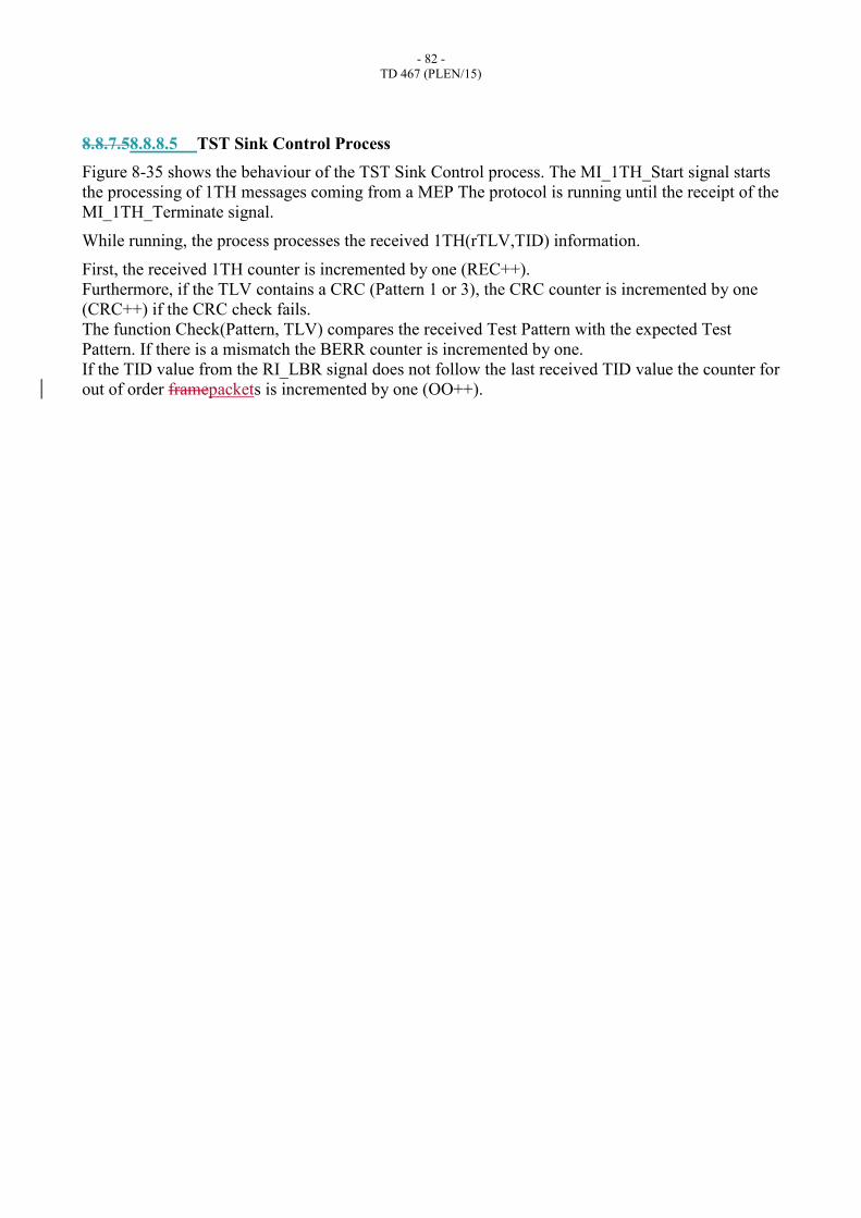
- 82 -
TD 467 (PLEN/15)
8.8.7.58.8.8.5 TST Sink Control Process
Figure 8-35 shows the behaviour of the TST Sink Control process. The MI_1TH_Start signal starts
the processing of 1TH messages coming from a MEP The protocol is running until the receipt of the
MI_1TH_Terminate signal.
While running, the process processes the received 1TH(rTLV,TID) information.
First, the received 1TH counter is incremented by one (REC++).
Furthermore, if the TLV contains a CRC (Pattern 1 or 3), the CRC counter is incremented by one
(CRC++) if the CRC check fails.
The function Check(Pattern, TLV) compares the received Test Pattern with the expected Test
Pattern. If there is a mismatch the BERR counter is incremented by one.
If the TID value from the RI_LBR signal does not follow the last received TID value the counter for
out of order framepackets is incremented by one (OO++).
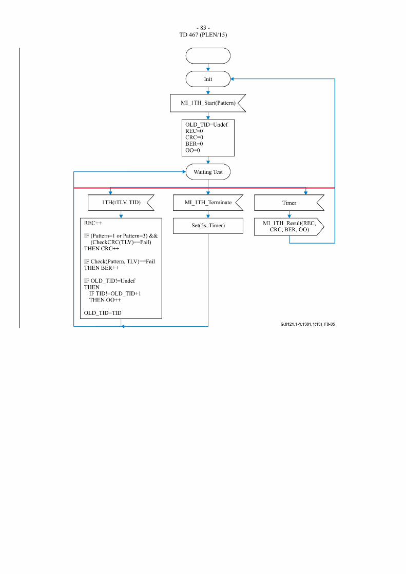
- 83 -
TD 467 (PLEN/15)
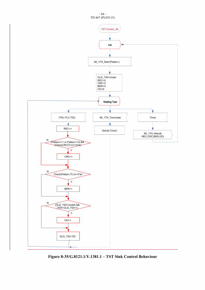
- 84 -
TD 467 (PLEN/15)
Figure 8-35/G.8121.1/Y.1381.1 – TST Sink Control Behaviour
Init
MI_TST_Start (SA,Pattern)
OLD_TID=Undef
REC=0CRC=0
BER=0
OO=0
Waiting Test
TST(rSA,rTLV,TID) MI_TST_Terminate
MI_TST_Result(
REC,CRC,BER,OO)
Timer
Set(5s,Timer)
Init
MI_1TH_Start (Pattern )
OLD_TID=Undef
REC=0CRC=0
BER=0
OO=0
Waiting Test
1TH( rTLV,TID) MI_1TH_Terminate
MI_1TH_Result(
REC,CRC,BER,OO)
Timer
Set(5s,Timer)
TST Control_Sk
REC++
OLD_TID=TID
N
CRC++
Y
(Pattern==1 or Pattern==3) &&
(CheckCRC(TLV)==Fail)
N
BER++
Y
Check(Pattern,TLV)==Fail
N
OO++
Y
(OLD_TID!=Undef) &&
(TID!=OLD_TID+1)
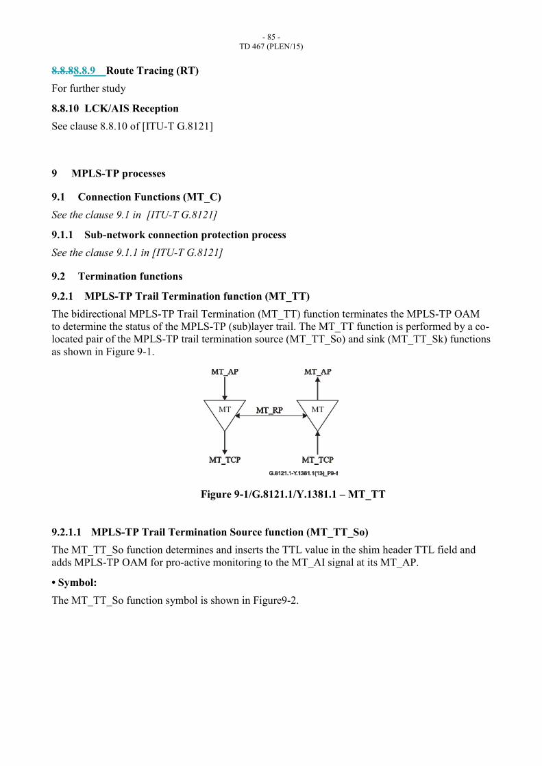
- 85 -
TD 467 (PLEN/15)
8.8.88.8.9 Route Tracing (RT)
For further study
8.8.10 LCK/AIS Reception
See clause 8.8.10 of [ITU-T G.8121]
9 MPLS-TP processes
9.1 Connection Functions (MT_C)
See the clause 9.1 in [ITU-T G.8121]
9.1.1 Sub-network connection protection process
See the clause 9.1.1 in [ITU-T G.8121]
9.2 Termination functions
9.2.1 MPLS-TP Trail Termination function (MT_TT)
The bidirectional MPLS-TP Trail Termination (MT_TT) function terminates the MPLS-TP OAM
to determine the status of the MPLS-TP (sub)layer trail. The MT_TT function is performed by a co-
located pair of the MPLS-TP trail termination source (MT_TT_So) and sink (MT_TT_Sk) functions
as shown in Figure 9-1.
Figure 9-1/G.8121.1/Y.1381.1 – MT_TT
9.2.1.1 MPLS-TP Trail Termination Source function (MT_TT_So)
The MT_TT_So function determines and inserts the TTL value in the shim header TTL field and
adds MPLS-TP OAM for pro-active monitoring to the MT_AI signal at its MT_AP.
• Symbol:
The MT_TT_So function symbol is shown in Figure9-2.
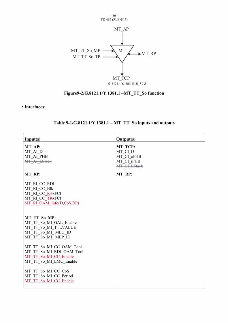
- 86 -
TD 467 (PLEN/15)
G.8121.1-Y.1381.1(13)_F9-2
MT_AP
MT_RP
MT_TCP
MT_TT_So_MP
MT_TT_So_TP
MT
Figure9-2/G.8121.1/Y.1381.1 –MT_TT_So function
• Interfaces:
Table 9-1/G.8121.1/Y.1381.1 – MT_TT_So inputs and outputs
Input(s) Output(s)
MT_AP: MT_AI_D
MT_AI_PHB
MT_AI_LStack
MT_RP:
MT_RI_CC_RDI
MT_RI_CC_Blk
MT_RI_CC_RTxFCl
MT_RI_CC_TRxFCf
MT_RI_OAM_Info(D,CoS,DP)
MT_TT_So_MP: MT_TT_So_MI_GAL_Enable
MT_TT_So_MI_TTLVALUE
MT_TT_So_MI_ MEG_ID
MT_TT_So_MI_ MEP_ID
MT_TT_So_MI_CC_OAM_Tool
MT_TT_So_MI_RDI_OAM_Tool
MT_TT_So_MI_CC_Enable
MT_TT_So_MI_LMC_Enable
MT_TT_So_MI_CC_CoS
MT_TT_So_MI_CC_Period
MT_TT_So_MI_CC_Enable
MT_TCP: MT_CI_D
MT_CI_oPHB
MT_CI_iPHB
MT_CI_LStack
MT_RP:
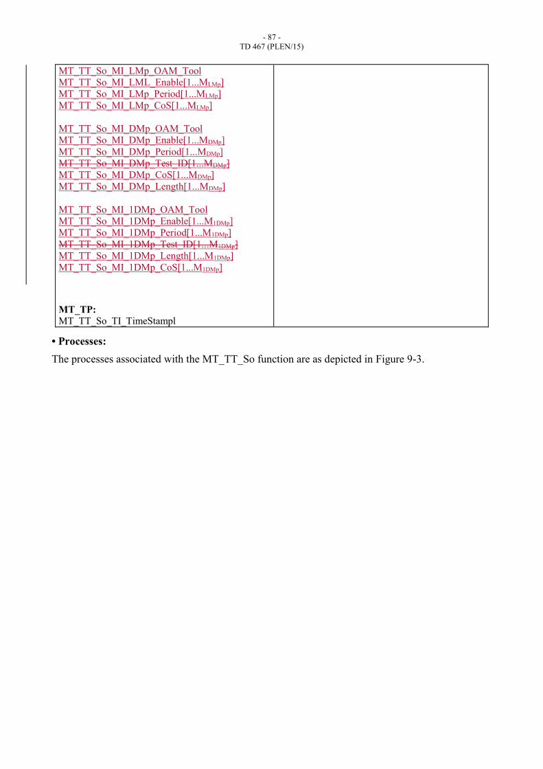
- 87 -
TD 467 (PLEN/15)
MT_TT_So_MI_LMp_OAM_Tool
MT_TT_So_MI_LML_Enable[1...MLMp]
MT_TT_So_MI_LMp_Period[1...MLMp]
MT_TT_So_MI_LMp_CoS[1...MLMp]
MT_TT_So_MI_DMp_OAM_Tool
MT_TT_So_MI_DMp_Enable[1...MDMp]
MT_TT_So_MI_DMp_Period[1...MDMp]
MT_TT_So_MI_DMp_Test_ID[1...MDMp]
MT_TT_So_MI_DMp_CoS[1...MDMp]
MT_TT_So_MI_DMp_Length[1...MDMp]
MT_TT_So_MI_1DMp_OAM_Tool
MT_TT_So_MI_1DMp_Enable[1...M1DMp]
MT_TT_So_MI_1DMp_Period[1...M1DMp]
MT_TT_So_MI_1DMp_Test_ID[1...M1DMp]
MT_TT_So_MI_1DMp_Length[1...M1DMp]
MT_TT_So_MI_1DMp_CoS[1...M1DMp]
MT_TP:
MT_TT_So_TI_TimeStampl
• Processes:
The processes associated with the MT_TT_So function are as depicted in Figure 9-3.
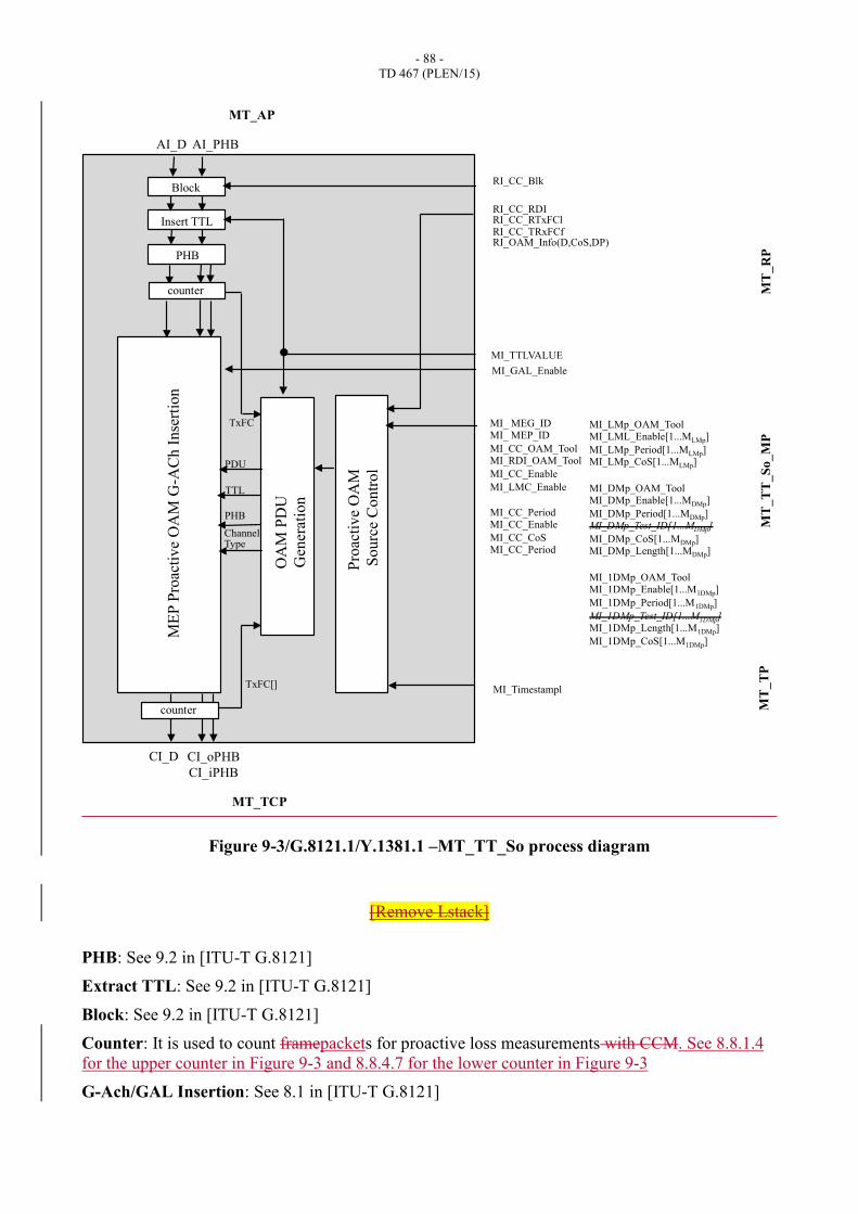
- 88 -
TD 467 (PLEN/15)
Figure 9-3/G.8121.1/Y.1381.1 –MT_TT_So process diagram
[Remove Lstack]
PHB: See 9.2 in [ITU-T G.8121]
Extract TTL: See 9.2 in [ITU-T G.8121]
Block: See 9.2 in [ITU-T G.8121]
Counter: It is used to count framepackets for proactive loss measurements with CCM. See 8.8.1.4
for the upper counter in Figure 9-3 and 8.8.4.7 for the lower counter in Figure 9-3
G-Ach/GAL Insertion: See 8.1 in [ITU-T G.8121]
CI_oPHB
CI_iPHB
MI_TTLVALUE
ME
P P
roac
tiv
e O
AM
G-A
Ch
In
sert
ion
PHB
AI_D AI_PHB
CI_D
MT_TCP
MT_AP
MT
_R
P
MT
_T
T_
So
_M
P
Insert TTL
Block
Pro
acti
ve
OA
M
So
urc
e C
on
trol
OA
M P
DU
Gen
erat
ion
counter
MI_GAL_Enable
RI_CC_RDI RI_CC_RTxFCl RI_CC_TRxFCf RI_OAM_Info(D,CoS,DP)
RI_CC_Blk
MI_ MEG_ID MI_ MEP_ID
MI_CC_OAM_Tool MI_RDI_OAM_Tool
MI_CC_Enable
MI_LMC_Enable
MI_CC_Period MI_CC_Enable
MI_CC_CoS MI_CC_Period
TxFC
PDU
TTL
MT
_T
P
Channel Type
PHB
MI_Timestampl
MI_LMp_OAM_Tool MI_LML_Enable[1...MLMp]
MI_LMp_Period[1...MLMp] MI_LMp_CoS[1...MLMp]
MI_DMp_OAM_Tool MI_DMp_Enable[1...MDMp]
MI_DMp_Period[1...MDMp] MI_DMp_Test_ID[1...MDMp]
MI_DMp_CoS[1...MDMp] MI_DMp_Length[1...MDMp]
MI_1DMp_OAM_Tool MI_1DMp_Enable[1...M1DMp]
MI_1DMp_Period[1...M1DMp]
MI_1DMp_Test_ID[1...M1DMp] MI_1DMp_Length[1...M1DMp]
MI_1DMp_CoS[1...M1DMp]
counter
TxFC[]
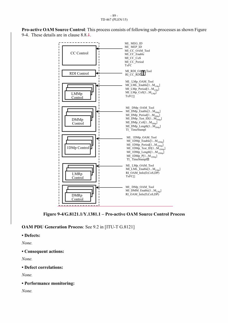
- 89 -
TD 467 (PLEN/15)
Pro-active OAM Source Control: This process consists of following sub-processes as shown Figure
9-4.. These details are in clause 8.8.1.
Figure 9-4/G.8121.1/Y.1381.1 – Pro-active OAM Source Control Process
OAM PDU Generation Process: See 9.2 in [ITU-T G.8121]
• Defects:
None.
• Consequent actions:
None.
• Defect correlations:
None.
• Performance monitoring:
None.
LMMp Control
1DMp Control
RDI Control
CC Control
DMMp Control
MI_RDI_OAM_Tool RI_CC_RDIII
MI_ MEG_ID MI_ MEP_ID
MI_CC_OAM_Tool MI_CC_Enable
MI_CC_CoS
MI_CC_Period TxFC
MI_ LMp_OAM_Tool MI_LML_Enable[1...MLMp]
MI_LMp_Period[1...MLMp] MI_LMp_CoS[1...MLMp]
TxFC[]
MI_ DMp_OAM_Tool MI_DMp_Enable[1...MDMp]
MI_DMp_Period[1...MDMp] MI_DMp_Test_ID[1...MDMp]
MI_DMp_CoS[1...MDMp]
MI_DMp_Length[1...MDMp] TI_ TimeStampl
MI_ 1DMp_OAM_Tool MI_1DMp_Enable[1...M1DMp]
MI_1DMp_Period[1...M1DMp] MI_1DMp_Test_ID[1...M1DMp]
MI_1DMp_Length[1...M1DMp]
MI_1DMp_P[1...M1DMp] TI_ TimeStamplII
LMRp Control
MI_ LMp_OAM_Tool MI_LML_Enable[1...MLMp]
RI_OAM_Info(D,CoS,DP) TxFC[]
DMRp Control
MI_ DMp_OAM_Tool MI_DMM_Enable[1...MLMp]
RI_OAM_Info(D,CoS,DP)

- 90 -
TD 467 (PLEN/15)
9.2.1.2 MPLS-TP Trail Termination Sink function (MT_TT_Sk)
The MT_TT_Sk function reports the state of the MPLS-TP Trail (Network Connection). It extracts
MPLS-TP trail OAM - for pro-active monitoring - from the MPLS-TP signal at its MT_TCP,
detects defects, counts during 1-second periods errors and defects to feed Performance Monitoring
when connected and forwards the defect information as backward indications to the companion
MT_TT_So function.
Note – The MT_TT_Sk function extracts and processes one level of MPLS-TP OAM irrespective of
the presence of more levels.
• Symbol:
The MT_TT_So function symbol is shown in Figure 9-5.
Figure 9-5/G.8121.1/Y.1381.1 – MT_TT_Sk function

- 91 -
TD 467 (PLEN/15)
• Interfaces:
Table 9-2/G.8121.1/Y.1381.1 – MT_TT_Sk inputs and outputs

- 92 -
TD 467 (PLEN/15)
Input(s) Output(s)
MT_TCP:
MT_CI_D
MT_CI_iPHB
MT_CI_oPHB
MT_CI_SSF
MT_CI_Lstack
MT_RP:
MT_TT_Sk_MP:
MT_TT_Sk_MI_GAL_Enable
MT_TT_Sk_MI_ MEG_ID
MT_TT_Sk_MI_ PeerMEP_ID
MT_TT_Sk_MI_ CC_OAM_Tool
MT_TT_Sk_MI_ RDI_OAM_Tool
MT_TT_Sk_MI_CC_Enable
MT_TT_Sk_MI_LMC_Enable
MT_TT_Sk_MI_CC_Period
MT_TT_Sk_MI_CC_CoS
MT_TT_Sk_MI_Get_SvdCC
MT_TT_Sk_MI_LM_DEGM
MT_TT_Sk_MI_LM_M
MT_TT_Sk_MI_LM_DEGTHR
MT_TT_Sk_MI_LM_TFMIN
MT_TT_Sk_MI_LMp_OAM_Tool [1... MLMp]
MT_TT_Sk_MI_LML_Enable[1... MLMp]
MT_TT_Sk_MI_LMp_CoS[1... MLMp]
MT_TT_Sk_MI_DMp_OAM_Tool[1… MDMp]
MT_TT_Sk_MI_DMp_Enable[1… MDMp]
MT_TT_Sk_MI_DMp_CoS[1… MDMp]
MT_TT_Sk_MI_1DMp_OAM_Tool[1...M1DMp]
MT_TT_Sk_MI_1DMp_Enable[1...M1DMp]
MT_TT_Sk_MI_1DMp_Test_ID[1...M1DMp]
MT_TT_Sk_MI_1second
MT_TP:
MT_TT_Sk_TI_TimeStampl
MT_AP:
MT_AI_D
MT_AI_PHB
MT_AI_TSF
MT_AI_TSD
MT_AI_AIS
MT_AI_LStack
MT_RP:
MT_RI_CC_RDI
MT_RI_CC_Blk
MT_RI_CC_RxFCl
MT_RI_CC_TxFCf
MT_RI_OAM_Info(D,CoS,DP)
MT_TT_Sk_MP:
MT_TT_Sk_MI_SvdCC
MT_TT_Sk_MI_cSSF
MT_TT_Sk_MI_cLCK
MT_TT_Sk_MI_cLOC
MT_TT_Sk_MI_cMMG
MT_TT_Sk_MI_cUNM
MT_TT_Sk_MI_cUNP
MT_TT_Sk_MI_cUNC
MT_TT_Sk_MI_cDEG
MT_TT_Sk_MI_cRDI
MT_TT_Sk_MI_pN_LF
MT_TT_Sk_MI_pN_TF
MT_TT_Sk_MI_pF_LF
MT_TT_Sk_MI_pF_TF
MT_TT_Sk_MI_pN_LF[1...P]
MT_TT_Sk_MI_pN_TF[1...P]
MT_TT_Sk_MI_pF_LF[1...P]
MT_TT_Sk_MI_pF_TF[1...P]
MT_TT_Sk_MI_pF_DS
MT_TT_Sk_MI_pN_DS
MT_TT_Sk_MI_pB_FD[1...P]
MT_TT_Sk_MI_pB_FDV[1...P]
MT_TT_Sk_MI_pN_FD[1...P]
MT_TT_Sk_MI_pN_FDV[1...P]
MT_TT_Sk_MI_pF_FD[1...P]
MT_TT_Sk_MI_pF_FDV[1...P]
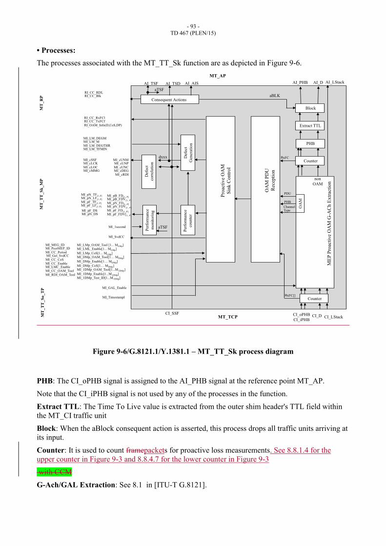
- 93 -
TD 467 (PLEN/15)
• Processes:
The processes associated with the MT_TT_Sk function are as depicted in Figure 9-6.
Figure 9-6/G.8121.1/Y.1381.1 – MT_TT_Sk process diagram
PHB: The CI_oPHB signal is assigned to the AI_PHB signal at the reference point MT_AP.
Note that the CI_iPHB signal is not used by any of the processes in the function.
Extract TTL: The Time To Live value is extracted from the outer shim header's TTL field within
the MT_CI traffic unit
Block: When the aBlock consequent action is asserted, this process drops all traffic units arriving at
its input.
Counter: It is used to count framepackets for proactive loss measurements. See 8.8.1.4 for the
upper counter in Figure 9-3 and 8.8.4.7 for the lower counter in Figure 9-3
with CCM
G-Ach/GAL Extraction: See 8.1 in [ITU-T G.8121].
ME
P P
roac
tiv
e O
AM
G-A
Ch E
xtr
acti
on
Block
Consequent Actions
Def
ect
corr
elat
ion
Per
form
ance
mo
nit
ori
ng
non
OAM
CI_D CI_oPHB
CI_iPHB
Counter
CI_SSF
AI_D AI_PHB
aBLK
AI_TSF
aTSF
MT_TCP
MT_AP
MT
_T
T_S
k_M
P
MT
_R
P
PHB
Extract TTL
OA
M P
DU
Rec
epti
on
Pro
acti
ve
OA
M
Sin
k C
ontr
ol
Def
ect
Gen
erat
ion
Per
form
ance
cou
nte
r
aTSF
RxFC
MI_LM_DEGM MI_LM_M MI_LM_DEGTHR MI_LM_TFMIN
MI_cSSF MI_cLCK MI_cLOC MI_cMMG
dxxx
RI_CC_RDI, RI_CC_Blk
MI_SvdCC
MI_MEG_ID MI_PeerMEP_ID MI_CC_Period MI_Get_SvdCC MI_CC_CoS MI_CC_Enable MI_LMC_Enable MI_CC_OAM_Tool MI_RDI_OAM_Tool
MI_cUNM MI_cUNP MI_cUNC MI_cDEG MI_cRDI
AI_TSD AI_AIS
RI_CC_RxFCl RI_CC_TxFCf RI_OAM_Info(D,CoS,DP)
MI_GAL_Enable
PDU
PHB
Channel Type
MT
_T
T_
So
_T
P
OA
M
AI_LStack
CI_LStack
MI_pN_TF[1..P] MI_pN_LF[1..P] MI_pF_TF[1..P] MI_pF_LF[1..P]
MI_1second
MI_Timestampl
MI_LMp_OAM_Tool [1... MLMp] MI_LML_Enable[1... MLMp]
MI_LMp_CoS[1... MLMp] MI_DMp_OAM_Tool[1… MDMp]
MI_DMp_Enable[1… MDMp]
MI_DMp_CoS[1… MDMp] MI_1DMp_OAM_Tool[1...M1DMp]
MI_1DMp_Enable[1...M1DMp] MI_1DMp_Test_ID[1...M1DMp]
MI_pB_FD[1...P] MI_pB_FDV[1...P]
MI_pN_FD[1...P] MI_pN_FDV[1...P]
MI_pF_FD[1...P]
MI_pF_FDV[1...P]
MI_pF_DS MI_pN_DS
Counter RxFC[]
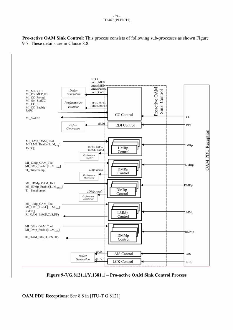
- 94 -
TD 467 (PLEN/15)
Pro-active OAM Sink Control: This process consists of following sub-processes as shown Figure
9-7. These details are in Clause 8.8.
Figure 9-7/G.8121.1/Y.1381.1 – Pro-active OAM Sink Control Process
OAM PDU Receptions: See 8.8 in [ITU-T G.8121]
RDI Control
CC Control
dRDI
CC
RDI
LCK Control dLCK
LCK
AIS Control dAIS
AIS
MI_MEG_ID MI_PeerMEP_ID MI_CC_Period MI_Get_SvdCC MI_CC_P MI_CC_Enable RxFC
MI_SvdCC
OA
M P
DU
Rec
epti
on
Pro
acti
ve
OA
M
Sin
k C
on
tro
l
Performance counter
expCC unexpMEG unexpMEP unexpPeriod unexpCoS
Defect Generation
TxFCl, RxFC,
TxRCb, RxFCb
LMMp Control
DMMp Control
MI_ DMp_OAM_Tool MI_DMp_Enable[1...M1DMp]
TI_ TimeStampl
MI_DMp_OAM_Tool MI_DMp_Enable[1...MLMp]
RI_OAM_Info(D,CoS,DP)
LMRp
DMRp
LMRp Control
DMRp Control
MI_ LMp_OAM_Tool MI_LML_Enable[1...MLMp]
RxFC[] RI_OAM_Info(D,CoS,DP)
LMMp
DMMp
MI_ LMp_OAM_Tool MI_LML_Enable[1...MLMp]
RxFC[]
MI_ 1DMp_OAM_Tool MI_1DMp_Enable[1...M1DMp]
TI_ TimeStampl
DMRp
DMRp Control
DMp result
1DMp result
TxFCl, RxFC,
TxRCb, RxFCb
Performance
counter
Defect Generation
Performance
Monitoring
Performance
Monitoring
Defect Generation
- 95 -
TD 467 (PLEN/15)
Defect Generation: This process raises and clears the defects as defined in clause 6.1 in in [ITU-T
G.8121] that are dLOC, dMMG, dUNM, dDEG, dUNP, dUNPr, dRDI, dAIS, dLCK
• Defects:
This function detects dLOC[i], dUNL, dMMG, dUNM, dDEG, dUNP, dUNPr, dRDI[i], dAIS,
dLCK.
• Consequent actions:
aBLK (dUNL or dMMG or dUNM)
Note that dUNP and dUNPr does not contribute to aBLK, because a mismatch of periodicity is not
considered to be a security issue.
aTSF (dLOC and MI_CC_Enable) or (dAIS and not(MI_CC_Enable)) or (dLCK and
not(MI_CC_Enable)) or dUNL or dMMG or dUNM or CI_SSF
aTSD dDEG and (not aTSF)
aAIS aTSF
aRDI aTSF
• Defect correlations:
cLOC[i] dLOC[i] and (not dAIS) and (not dLCK) and (not CI_SSF) and (MI_CC_Enable)
cUNL dUNL
cMMG dMMG
cUNM dUNM
cDEG[1] dDEG[1] and (not dAIS) and (not dLCK) and (not CI_SSF) and (not (dLOC[1..n]
or dUNL or dMMG or dUNM)) and (MI_CC_Enable))
cUNP dUNP
cUNPr dUNPr
cRDI (dRDI[1..n]) and (MI_CC_Enable)
cSSF CI_SSF or dAIS
cLCK dLCK and (not dAIS)
• Performance monitoring:
pN_TF N_TF
pN_LF N_LF
pF_TF F_TF
pF_LF F_LF
pN_DS aTSF
pF_DS aRDI[1]
pB_FD B_FD
pB_FDV B_FDV
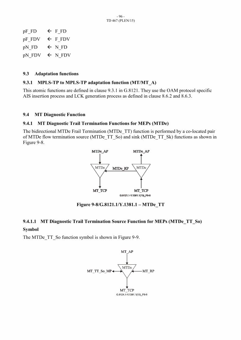
- 96 -
TD 467 (PLEN/15)
pF_FD F_FD
pF_FDV F_FDV
pN_FD N_FD
pN_FDV N_FDV
9.3 Adaptation functions
9.3.1 MPLS-TP to MPLS-TP adaptation function (MT/MT_A)
This atomic functions are defined in clause 9.3.1 in G.8121. They use the OAM protocol specific
AIS insertion process and LCK generation process as defined in clause 8.6.2 and 8.6.3.
9.4 MT Diagnostic Function
9.4.1 MT Diagnostic Trail Termination Functions for MEPs (MTDe)
The bidirectional MTDe Frail Termination (MTDe_TT) function is performed by a co-located pair
of MTDe flow termination source (MTDe_TT_So) and sink (MTDe_TT_Sk) functions as shown in
Figure 9-8.
Figure 9-8/G.8121.1/Y.1381.1 – MTDe_TT
9.4.1.1 MT Diagnostic Trail Termination Source Function for MEPs (MTDe_TT_So)
Symbol
The MTDe_TT_So function symbol is shown in Figure 9-9.
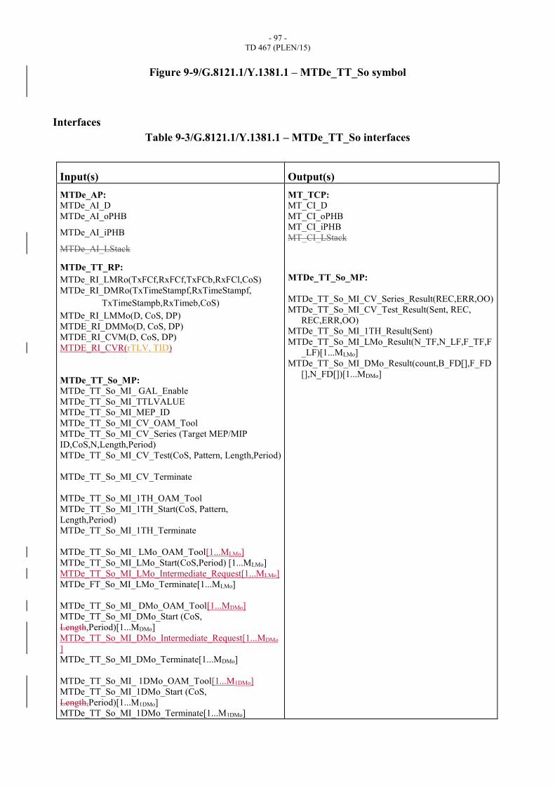
- 97 -
TD 467 (PLEN/15)
Figure 9-9/G.8121.1/Y.1381.1 – MTDe_TT_So symbol
Interfaces
Table 9-3/G.8121.1/Y.1381.1 – MTDe_TT_So interfaces
Input(s) Output(s)
MTDe_AP: MTDe_AI_D
MTDe_AI_oPHB
MTDe_AI_iPHB
MTDe_AI_LStack
MTDe_TT_RP:
MTDe_RI_LMRo(TxFCf,RxFCf,TxFCb,RxFCl,CoS)
MTDe_RI_DMRo(TxTimeStampf,RxTimeStampf,
TxTimeStampb,RxTimeb,CoS)
MTDe_RI_LMMo(D, CoS, DP)
MTDE_RI_DMMo(D, CoS, DP)
MTDE_RI_CVM(D, CoS, DP)
MTDE_RI_CVR(rTLV, TID)
MTDe_TT_So_MP: MTDe_TT_So_MI_ GAL_Enable
MTDe_TT_So_MI_TTLVALUE
MTDe_TT_So_MI_MEP_ID
MTDe_TT_So_MI_CV_OAM_Tool
MTDe_TT_So_MI_CV_Series (Target MEP/MIP
ID,CoS,N,Length,Period)
MTDe_TT_So_MI_CV_Test(CoS, Pattern, Length,Period)
MTDe_TT_So_MI_CV_Terminate
MTDe_TT_So_MI_1TH_OAM_Tool
MTDe_TT_So_MI_1TH_Start(CoS, Pattern,
Length,Period)
MTDe_TT_So_MI_1TH_Terminate
MTDe_TT_So_MI_ LMo_OAM_Tool[1...MLMo]
MTDe_TT_So_MI_LMo_Start(CoS,Period) [1...MLMo]
MTDe_TT_So_MI_LMo_Intermediate_Request[1...MLMo]
MTDe_FT_So_MI_LMo_Terminate[1...MLMo]
MTDe_TT_So_MI_ DMo_OAM_Tool[1...MDMo]
MTDe_TT_So_MI_DMo_Start (CoS,
Length,Period)[1...MDMo]
MTDe_TT_So_MI_DMo_Intermediate_Request[1...MDMo
]
MTDe_TT_So_MI_DMo_Terminate[1...MDMo]
MTDe_TT_So_MI_ 1DMo_OAM_Tool[1...M1DMo]
MTDe_TT_So_MI_1DMo_Start (CoS,
Length,Period)[1...M1DMo]
MTDe_TT_So_MI_1DMo_Terminate[1...M1DMo]
MT_TCP: MT_CI_D
MT_CI_oPHB
MT_CI_iPHB
MT_CI_LStack
MTDe_TT_So_MP:
MTDe_TT_So_MI_CV_Series_Result(REC,ERR,OO)
MTDe_TT_So_MI_CV_Test_Result(Sent, REC,
REC,ERR,OO)
MTDe_TT_So_MI_1TH_Result(Sent)
MTDe_TT_So_MI_LMo_Result(N_TF,N_LF,F_TF,F
_LF)[1...MLMo]
MTDe_TT_So_MI_DMo_Result(count,B_FD[],F_FD
[],N_FD[])[1...MDMo]
- 98 -
TD 467 (PLEN/15)
MTDe_TT_So_TP:
MTDe_TT_So_TI_ TimeStampl
Processes
The processes associated with the MTDe_TT_So function are as depicted in Figure 9-10.
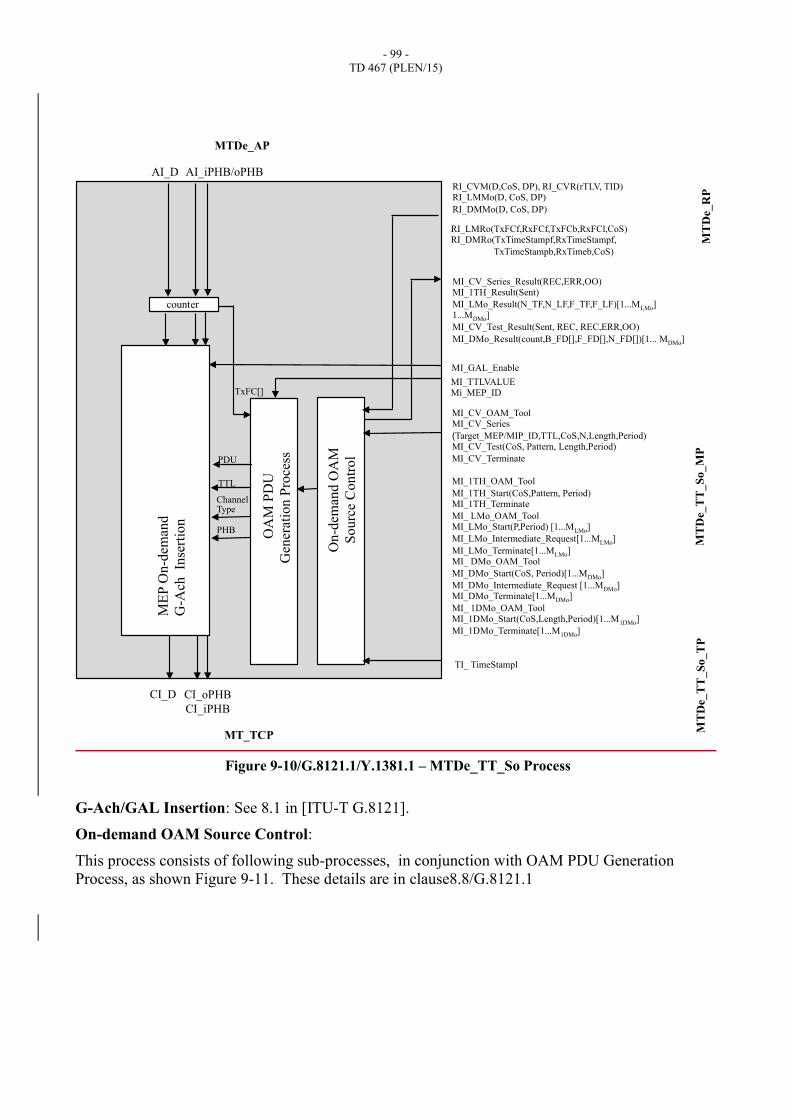
- 99 -
TD 467 (PLEN/15)
Figure 9-10/G.8121.1/Y.1381.1 – MTDe_TT_So Process
G-Ach/GAL Insertion: See 8.1 in [ITU-T G.8121].
On-demand OAM Source Control:
This process consists of following sub-processes, in conjunction with OAM PDU Generation
Process, as shown Figure 9-11.. These details are in clause8.8/G.8121.1
CI_oPHB
CI_iPHB
MI_TTLVALUE Mi_MEP_ID
ME
P O
n-d
eman
d
G-A
ch
Inse
rtio
n
AI_D AI_iPHB/oPHB
CI_D
MT_TCP
MTDe_AP
MT
De_
RP
M
TD
e_T
T_
So
_M
P
On
-dem
and
OA
M
So
urc
e C
on
tro
l
OA
M P
DU
Gen
erat
ion P
roce
ss
counter
MI_GAL_Enable
TxFC[]
RI_CVM(D,CoS, DP), RI_CVR(rTLV, TID) RI_LMMo(D, CoS, DP)
RI_DMMo(D, CoS, DP)
RI_LMRo(TxFCf,RxFCf,TxFCb,RxFCl,CoS) RI_DMRo(TxTimeStampf,RxTimeStampf,
TxTimeStampb,RxTimeb,CoS)
TI_ TimeStampl
MT
De_
TT
_S
o_
TP
MI_CV_OAM_Tool MI_CV_Series
(Target_MEP/MIP_ID,TTL,CoS,N,Length,Period) MI_CV_Test(CoS, Pattern, Length,Period)
MI_CV_Terminate
MI_1TH_OAM_Tool
MI_1TH_Start(CoS,Pattern, Period) MI_1TH_Terminate
MI_ LMo_OAM_Tool MI_LMo_Start(P,Period) [1...MLMo]
MI_LMo_Intermediate_Request[1...MLMo]
MI_LMo_Terminate[1...MLMo] MI_ DMo_OAM_Tool
MI_DMo_Start(CoS, Period)[1...MDMo]
MI_DMo_Intermediate_Request [1...MDMo] MI_DMo_Terminate[1...MDMo]
MI_ 1DMo_OAM_Tool MI_1DMo_Start(CoS,Length,Period)[1...M1DMo]
MI_1DMo_Terminate[1...M1DMo]
MI_CV_Series_Result(REC,ERR,OO) MI_1TH_Result(Sent)
MI_LMo_Result(N_TF,N_LF,F_TF,F_LF)[1...MLMo] 1...MDMo]
MI_CV_Test_Result(Sent, REC, REC,ERR,OO)
MI_DMo_Result(count,B_FD[],F_FD[],N_FD[])[1... MDMo]
PDU
TTL
Channel Type
PHB

- 100 -
TD 467 (PLEN/15)
Figure 9-11/G.8121.1/Y.1381.1 – On-demand OAM Source Control Process
On-demand OAM PDU Generation Process: See 8.8 in [ITU-T G.8121]
Counter Process: See 8.8.5.7 in [ITU-T G.8121.1]
Defects None.
Consequent actions None.
Defect correlations None.
Performance monitoring None.
9.4.1.2 MT Diagnostic Trail Termination Sink Function for MEPs (MTDe_TT_Sk)
Symbol
The MTDe_TT_Sk function symbol is shown in Figure 9-12.
1DMo Control
RI_DMRo(TxT.S.f,RxT.S.f,TxT.S.b,RxT.b,P,TestID)
MI_DMo_Result(count,B_FD[],F_FD[],N_FD[])[1…MDMo]
MI_1DMo_OAM_Tool[1...M1DMo] MI_1DMo_Start (CoS, Period)[1...M1DMo]
MI_1DMo_Terminate[1...M1DMo]
TI_TimeStampl
CVo Control
RI_CVM(D, CoS, DP), RI_CVR(rTLV, TID) MI_CV_Series(Target MEP/MIP_ID,TTL,P,DP,N,
Length, Period)
MI_CV_Series_Result(REC,ERR,OO)
LMo Control
RI_LMRo(TxFCf,RxFCf,TxFCb,RxFCl,CoS)
MI_LMo_Result(N_TF,N_LF,F_TF,F_LF)[1…MLMo]
MI_LMo_OAM_Tool [1..MLMo] MI_LMo_Start(CoS, Periord) [1..MLMo] MI_LMo_Terminate[1..MLMo], MI_LMo_Intermediate_Request[1..MLMo] TxFC[]
DMo Control
1DMo
CVo
LMMo
LMRo
DMMo
DMRo
MI_DMo_OAM_Tool[1..MDMo], MI_DMo_Start(CoS,Periord)[1..MDMo], MI_DMo_Terminate[1..MDMo],DMo_Intermediate_Request[1...MDMo
]
RI_LMMo(D, CoS, DP) RI_DMMo(D, CoS, DP)
On-demand OAM
Control Source
Process OAM PDU
Geneation Process
DMo/1DMo control
TST (1TH) Control
1DT
MI_1TH_OAM_Tool MI_1TH_Start(CoS, Pattern, Length,Period)
MI_1TH_Terminate
MI_1DT_Result(Sent)
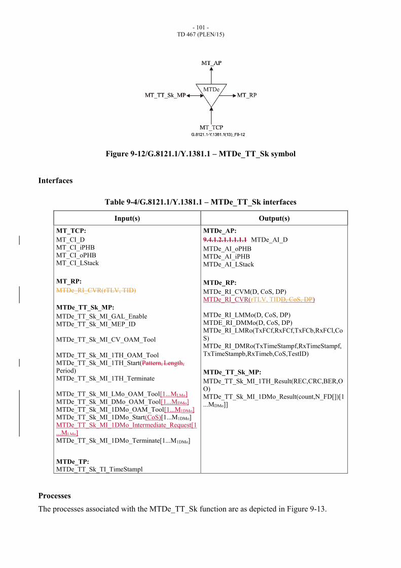
- 101 -
TD 467 (PLEN/15)
Figure 9-12/G.8121.1/Y.1381.1 – MTDe_TT_Sk symbol
Interfaces
Table 9-4/G.8121.1/Y.1381.1 – MTDe_TT_Sk interfaces
Input(s) Output(s)
MT_TCP:
MT_CI_D
MT_CI_iPHB
MT_CI_oPHB
MT_CI_LStack
MT_RP:
MTDe_RI_CVR(rTLV, TID)
MTDe_TT_Sk_MP:
MTDe_TT_Sk_MI_GAL_Enable
MTDe_TT_Sk_MI_MEP_ID
MTDe_TT_Sk_MI_CV_OAM_Tool
MTDe_TT_Sk_MI_1TH_OAM_Tool
MTDe_TT_Sk_MI_1TH_Start(Pattern, Length,
Period)
MTDe_TT_Sk_MI_1TH_Terminate
MTDe_TT_Sk_MI_LMo_OAM_Tool[1...MLMo]
MTDe_TT_Sk_MI_DMo_OAM_Tool[1...MDMo]
MTDe_TT_Sk_MI_1DMo_OAM_Tool[1...M1DMo]
MTDe_TT_Sk_MI_1DMo_Start(CoS)[1...M1DMo]
MTDe_TT_Sk_MI_1DMo_Intermediate_Request[1
...MLMo]
MTDe_TT_Sk_MI_1DMo_Terminate[1...M1DMo]
MTDe_TP:
MTDe_TT_Sk_TI_TimeStampl
MTDe_AP:
9.4.1.2.1.1.1.1.1 MTDe_AI_D
MTDe_AI_oPHB
MTDe_AI_iPHB
MTDe_AI_LStack
MTDe_RP:
MTDe_RI_CVM(D, CoS, DP)
MTDe_RI_CVR(rTLV, TIDD, CoS, DP)
MTDe_RI_LMMo(D, CoS, DP)
MTDE_RI_DMMo(D, CoS, DP)
MTDe_RI_LMRo(TxFCf,RxFCf,TxFCb,RxFCl,Co
S)
MTDe_RI_DMRo(TxTimeStampf,RxTimeStampf,
TxTimeStampb,RxTimeb,CoS,TestID)
MTDe_TT_Sk_MP:
MTDe_TT_Sk_MI_1TH_Result(REC,CRC,BER,O
O)
MTDe_TT_Sk_MI_1DMo_Result(count,N_FD[])[1
...MDMo]]
Processes
The processes associated with the MTDe_TT_Sk function are as depicted in Figure 9-13.
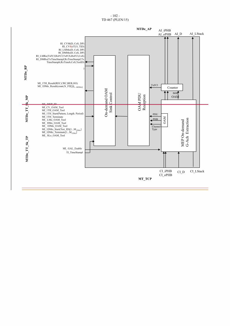
- 102 -
TD 467 (PLEN/15)
M
EP
On-d
eman
d
G-A
ch
Ex
trac
tio
n
OA
M
non
OAM
CI_D CI_iPHB
CI_oPHB
Counter
AI_D AI_iPHB
AI_oPHB
MT_TCP
MTDe_AP M
TD
e_T
T_
Sk
_M
P
MT
De_
RP
OA
M P
DU
Rec
epti
on
On
-dem
and
OA
M
Sin
k C
on
tro
l
TxFCl
MI_ MEP_ID
MI_CV_OAM_Tool MI_1TH_OAM_Tool
MI_1TH_Start(Pattern, Length. Period)
MI_1TH_Terminate MI_ LMo_OAM_Tool
MI_ DMo_OAM_Tool MI_ 1DMo_OAM_Tool
MI_1DMo_Start(Test_ID)[1...M1DMo] MI_1DMo_Terminate[1...M1DMo]
MI_ SLo_OAM_Tool
RI_CVM(D, CoS, DP) RI_CVR(rTLV, TID)
RI_LMMo(D, CoS, DP) RI_DMMo(D, CoS, DP)
RI_LMRo(TxFCf,RxFCf,TxFCb,RxFCl,CoS)
RI_DMRo(TxTimeStampf,RxTimeStampf,TxTimeStampb,RxTimeb,CoS,TestID)
)
MI_1TH_Result(REC,CRC,BER,OO) MI_1DMo_Result(count,N_FD[])[1...MDMo]]
MT
De_T
T_
Sk
_T
P
MI_ GAL_Enable
TI_TimeStampl
CI_LStack
AI_LStack
PDU
Channel Type
PHB
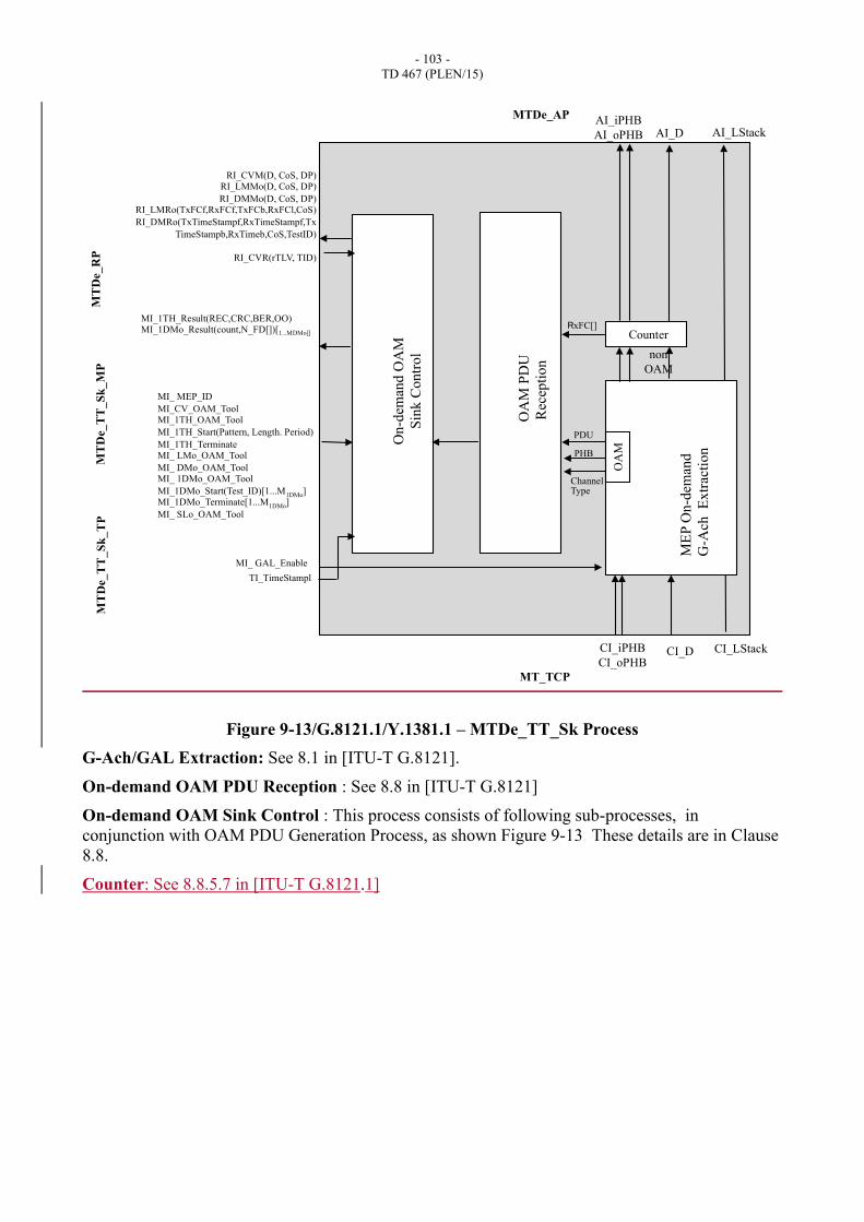
- 103 -
TD 467 (PLEN/15)
Figure 9-13/G.8121.1/Y.1381.1 – MTDe_TT_Sk Process
G-Ach/GAL Extraction: See 8.1 in [ITU-T G.8121].
On-demand OAM PDU Reception : See 8.8 in [ITU-T G.8121]
On-demand OAM Sink Control : This process consists of following sub-processes, in
conjunction with OAM PDU Generation Process, as shown Figure 9-13. These details are in Clause
8.8.
Counter: See 8.8.5.7 in [ITU-T G.8121.1]
ME
P O
n-d
eman
d
G-A
ch
Ex
trac
tio
n
OA
M
non
OAM
CI_D CI_iPHB
CI_oPHB
Counter
AI_D AI_iPHB
AI_oPHB
MT_TCP
MTDe_AP M
TD
e_T
T_
Sk
_M
P
MT
De_
RP
OA
M P
DU
Rec
epti
on
On
-dem
and
OA
M
Sin
k C
on
tro
l
RxFC[]
MI_ MEP_ID
MI_CV_OAM_Tool MI_1TH_OAM_Tool
MI_1TH_Start(Pattern, Length. Period)
MI_1TH_Terminate MI_ LMo_OAM_Tool
MI_ DMo_OAM_Tool MI_ 1DMo_OAM_Tool
MI_1DMo_Start(Test_ID)[1...M1DMo] MI_1DMo_Terminate[1...M1DMo]
MI_ SLo_OAM_Tool
RI_CVM(D, CoS, DP) RI_LMMo(D, CoS, DP)
RI_DMMo(D, CoS, DP) RI_LMRo(TxFCf,RxFCf,TxFCb,RxFCl,CoS)
RI_DMRo(TxTimeStampf,RxTimeStampf,Tx
TimeStampb,RxTimeb,CoS,TestID)
RI_CVR(rTLV, TID)
MI_1TH_Result(REC,CRC,BER,OO) MI_1DMo_Result(count,N_FD[])[1...MDMo]]
MT
De_T
T_
Sk
_T
P
MI_ GAL_Enable
TI_TimeStampl
CI_LStack
AI_LStack
PDU
Channel Type
PHB
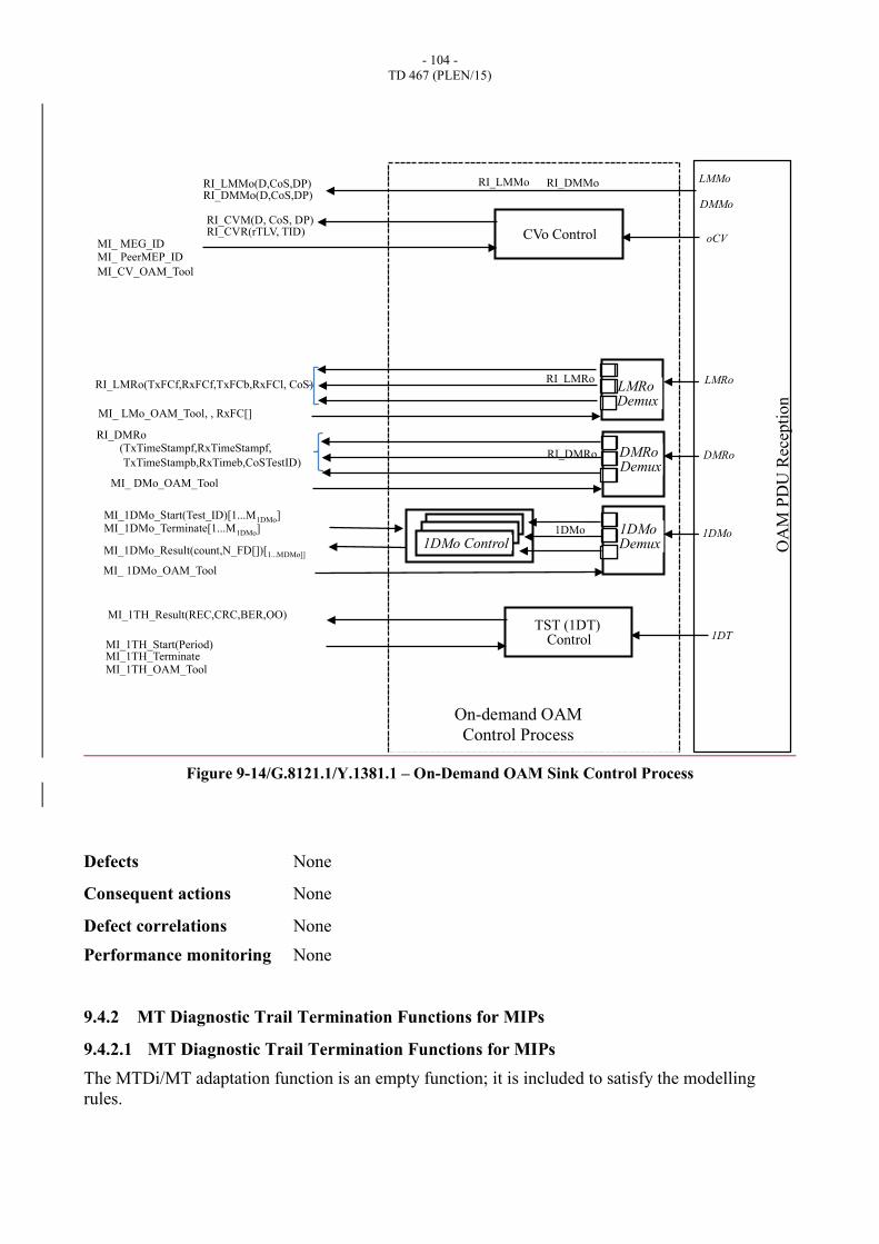
- 104 -
TD 467 (PLEN/15)
Figure 9-14/G.8121.1/Y.1381.1 – On-Demand OAM Sink Control Process
Defects None
Consequent actions None
Defect correlations None
Performance monitoring None
9.4.2 MT Diagnostic Trail Termination Functions for MIPs
9.4.2.1 MT Diagnostic Trail Termination Functions for MIPs
The MTDi/MT adaptation function is an empty function; it is included to satisfy the modelling
rules.
DMMo
LMMo
OA
M P
DU
Rec
epti
on
RI_CVM(D, CoS, DP) RI_CVR(rTLV, TID)
oCV
1DMo Control
LMRo Demux
X
Y
Z
DMRo Demux
X
Y
Z
1DMo Demux
X
Y
Z
LMRo
DMRo
1DMo 1DMo
RI_DMMo RI_LMMo
RI_DMRo
RI_LMMo(D,CoS,DP) RI_DMMo(D,CoS,DP)
RI_DMRo (TxTimeStampf,RxTimeStampf,
TxTimeStampb,RxTimeb,CoSTestID)
MI_1DMo_Result(count,N_FD[])[1...MDMo]]
RI_LMRo RI_LMRo(TxFCf,RxFCf,TxFCb,RxFCl, CoS)
MI_1DMo_Start(Test_ID)[1...M1DMo] MI_1DMo_Terminate[1...M1DMo]
MI_ DMo_OAM_Tool
MI_ 1DMo_OAM_Tool
MI_ LMo_OAM_Tool, , RxFC[]
MI_ MEG_ID MI_ PeerMEP_ID
MI_CV_OAM_Tool
CVo Control
On-demand OAM
Control Process
MI_1TH_Start(Period) MI_1TH_Terminate MI_1TH_OAM_Tool
1DT TST (1DT)
Control
MI_1TH_Result(REC,CRC,BER,OO)
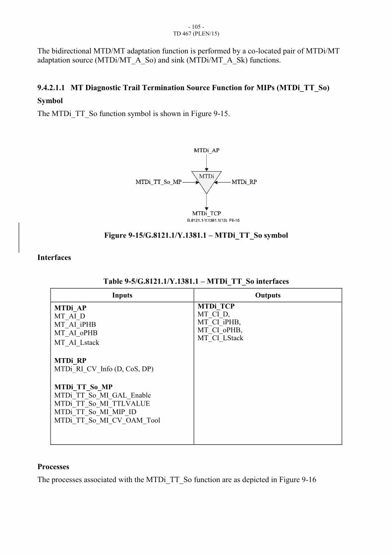
- 105 -
TD 467 (PLEN/15)
The bidirectional MTD/MT adaptation function is performed by a co-located pair of MTDi/MT
adaptation source (MTDi/MT_A_So) and sink (MTDi/MT_A_Sk) functions.
9.4.2.1.1 MT Diagnostic Trail Termination Source Function for MIPs (MTDi_TT_So)
Symbol
The MTDi_TT_So function symbol is shown in Figure 9-15.
Figure 9-15/G.8121.1/Y.1381.1 – MTDi_TT_So symbol
Interfaces
Table 9-5/G.8121.1/Y.1381.1 – MTDi_TT_So interfaces
Inputs Outputs
MTDi_AP
MT_AI_D
MT_AI_iPHB
MT_AI_oPHB
MT_AI_Lstack
MTDi_RP
MTDi_RI_CV_Info (D, CoS, DP)
MTDi_TT_So_MP
MTDi_TT_So_MI_GAL_Enable
MTDi_TT_So_MI_TTLVALUE
MTDi_TT_So_MI_MIP_ID
MTDi_TT_So_MI_CV_OAM_Tool
MTDi_TCP MT_CI_D, MT_CI_iPHB, MT_CI_oPHB, MT_CI_LStack
Processes
The processes associated with the MTDi_TT_So function are as depicted in Figure 9-16
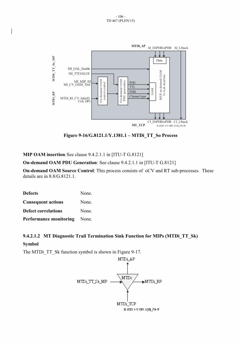
- 106 -
TD 467 (PLEN/15)
Figure 9-16/G.8121.1/Y.1381.1 – MTDi_TT_So Process
MIP OAM insertion:See clause 9.4.2.1.1 in [ITU-T G.8121]
On-demand OAM PDU Generation: See clause 9.4.2.1.1 in [ITU-T G.8121]
On-demand OAM Source Control: This process consists of oCV and RT sub-processes. These
details are in 8.8/G.8121.1.
Defects None.
Consequent actions None.
Defect correlations None.
Performance monitoring None.
9.4.2.1.2 MT Diagnostic Trail Termination Sink Function for MIPs (MTDi_TT_Sk)
Symbol
The MTDi_TT_Sk function symbol is shown in Figure 9-17.
G.8121.1-Y.1381.1(13)_F9-16
PDU
TTL
Channel type
PHB
On-d
em
an
d O
AM
PD
U g
enera
tio
n
On-d
em
an
d O
AM
sourc
e co
ntr
ol
ME
P o
n-d
em
and
OA
MG
-Ach
inser
tion
OA
M
Data
AI_D/iPHB/oPHB
CI_D/iPHB/oPHB
AI_LStack
CI_LStack
MI_MIP_IDMI_CV_OAM_Tool
MTDi_RI_CV_Info(D,CoS, DP)
MI_TTLVALUE
MI_GAL_Enable
MT_TCP
MTDi_AP
MT
Di_
RP
MT
Di_
TT
_So
_M
P
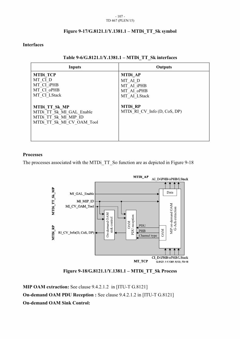
- 107 -
TD 467 (PLEN/15)
Figure 9-17/G.8121.1/Y.1381.1 – MTDi_TT_Sk symbol
Interfaces
Table 9-6/G.8121.1/Y.1381.1 – MTDi_TT_Sk interfaces
Inputs Outputs
MTDi_TCP
MT_CI_D
MT_CI_iPHB
MT_CI_oPHB
MT_CI_LStack
MTDi_TT_Sk_MP
MTDi_TT_Sk_MI_GAL_Enable
MTDi_TT_Sk_MI_MIP_ID
MTDi_TT_Sk_MI_CV_OAM_Tool
MTDi_AP
MT_AI_D
MT_AI_iPHB
MT_AI_oPHB
MT_AI_LStack
MTDi_RP MTDi_RI_CV_Info (D, CoS, DP)
Processes
The processes associated with the MTDi_TT_So function are as depicted in Figure 9-18
Figure 9-18/G.8121.1/Y.1381.1 – MTDi_TT_Sk Process
MIP OAM extraction: See clause 9.4.2.1.2 in [ITU-T G.8121]
On-demand OAM PDU Reception : See clause 9.4.2.1.2 in [ITU-T G.8121]
On-demand OAM Sink Control:
- 108 -
TD 467 (PLEN/15)
This process consists of oCV sub-processes. These details are in Clause 8.8.
Defects None.
Consequent actions None.
Defect correlations None.
Performance monitoring None.
9.4.2.2 MTDi to MT Adaptation functions (MTDi/MT_A)
See clause 9.4.2.2 in [ITU-T G.8121].
10 MPLS-TP to Non-MPLS-TP client adaptation functions
This atomic functions are defined in clause 10 in [ITU-T G.8121].
11 Non-MPLS-TP Server to MPLS-TP adaptation functions
These atomic functions are defined in clause 11 in [ITU-T G.8121]. They use the OAM protocol
specific AIS insertion process and LCK generation process as defined in clause 8.6.2 and 8.6.3.
______________________
RI_CC_RDI RI_CC_TxPCf RI_CC_RxPCl