Embed Size (px)
Citation preview

Schneider Electric Brands
TELEFAST® 2 Prewired SystemABE7
Class 8501
CONTENTS
Description PageGeneral Overview . . . . . . . . . . . . . . . . . . . . . . . . . . . . . . . . . . . . . . . . . . . . . . . . . . . . 2General Information . . . . . . . . . . . . . . . . . . . . . . . . . . . . . . . . . . . . . . . . . . . . . . . . . . 8Compatibility . . . . . . . . . . . . . . . . . . . . . . . . . . . . . . . . . . . . . . . . . . . . . . . . . . . . . . . 14Technical Overview . . . . . . . . . . . . . . . . . . . . . . . . . . . . . . . . . . . . . . . . . . . . . . . . . . 26Selection . . . . . . . . . . . . . . . . . . . . . . . . . . . . . . . . . . . . . . . . . . . . . . . . . . . . . . . . . . 36Approximate Dimensions . . . . . . . . . . . . . . . . . . . . . . . . . . . . . . . . . . . . . . . . . . . . . 52Wiring Diagrams . . . . . . . . . . . . . . . . . . . . . . . . . . . . . . . . . . . . . . . . . . . . . . . . . . . . 54Indexed Catalog Numbers . . . . . . . . . . . . . . . . . . . . . . . . . . . . . . . . . . . . . . . . . . . . 64

TELEFAST® 2 Prewired SystemGeneral Overview
2
2
13
7
12
A
B
General Overview
1 8
5
6
3
14
5
4
9
11 11
A
B
D
D
C
C
© 1999/2002 Schneider Electric All Rights Reserved 06/02

TELEFAST® 2 Prewired SystemGeneral Overview
06/02
Compatibility pages: 14 - 25
G
General Presentation
The Telefast 2 system is a set of products for rapid connection of I/O modules (24 Vdc discrete, analog and counter) to operative parts. It acts as a substitute for screw terminal blocks, remotely locating and partly eliminating the single-wire connection.The Telefast 2 system only connects to channels which have HE 10 and SUB-D connectors or to standard terminal blocks with a cabled connector. It consists of connecting cables and interface modules.The relay and connection functions, with or without polarity distribution, considerably reduce wiring time and eliminate the risk of error.
Connections Between the PLC and the Operative Part
Connection between the PLC and Telefast 2 modules
Telefast 2 modules connect directly by cables onto all discrete I/O modules with HE 10 connectors 1. I/O modules not supplied with HE 10 connectors are connected to Telefast 2 modules by means of cable connectors. These consist of a cable whose conductors (0.34 mm c.s.a.) are connected to the standard terminal block at one end and to the HE 10 connectors at the other. They are available in 4.92 ft. (1.5 meter) and 9.84 ft. (3-meter) lengths.
Connection between Telefast 2 modules and the operative part
The Telefast 2 range is suitable for all types of connection found in control system devices.A or nearby B are connections of I/O located in the PLC cabinet.Some modules 2 enable two wires (signal and common) or 3 wires (signal, 24 V, 0 V) to be connected directly from sensors or pre-actuators 13 when the latter are installed in the same enclosure or very close by. They effectively eliminate all intermediate terminal blocks.Other versions offer the possibility of adapting the voltage or current by removable relay modules 3 or of connecting analog signals 12.In cases where size is of prime importance D, fixed relay modules ABE7R1 6S111 8 4.92" (125 mm long) and passive modules ABE7H16R50 9 3.31" (84 mm long) reduce the required surface area by about 50% as compared with standard products.Connection of I/O located outside the PLC cabinet C.These modules 4 which connect connector leads from sensors or pre-actuators 11 fulfil the same function as traditional terminal blocks.IP65 dust and damp-proof connections for enclosures and cabinetsWhen the operative part has to be separate from the control part, enclosure feedthroughs are used to join HE 10 connectors and:- 40-way, rectangular, industrial connectors for 32-channel versions 5,- 19-way, cylindrical, CNOMO M23 connectors, for 8,12 and 16-channel versions 6. Eight-channel versions offer, in addition, the possibility of directly connecting the XSZ dust and damp-proof splitter blocks 14 for 8 sensors.In applications where the control cabinet is integral to the operative part, the cable gland assembly 7 enables the direct output of 3 Telefast 2 cables without additional connections.
Description of a Telefast 2 Modules
All modules in the Telefast 2 family have a standardized design and offer the common functions described below.
a = Optional functions
abcdefghijklm
20-way HE 10 connector24 Vdc power supply circuit fuseCan be mounted on 35 mm DIN3 mounting track24 Vdc display LED24 Vdc power supply terminal blockIsolator switch on 0 VdcChannel indication LED aCustomer label-holder/coverWiring diagramTest point for 0 2.3 mm plugUpper terminal blockLower terminal block, offset by 1/2 step aAdditional clip-on terminal block with 20 screw terminals a
Technical Overview pages: 26 - 35 Product Selection pages: 36 - 51 Approximate Dimensions, and Wiring Diagram pages: 52 - 63
d
c
b
a
g
e
h
i
j
k
f
lm
3© 1999/2002 Schneider Electric All Rights Reserved

TELEFAST® 2 Prewired SystemGeneral Overview
4
Compatibility pages: 14 - 25
ABE7H08R11
ABE7H16R31
ABE7H16R21
AB
Passive Modules
Designed to simplify I/O connection to a PLC within a control panel, the range of passive modules has the same functions as traditional terminal blocks to which they add, depending on the models, compact size, connection of proximity sensor commons (3-wire and type 2), LED indication, protected and isolated channels.
Terminal block modules
ABE7H��R11/R10: these products can be used to connect inputs or outputs. The commons are made on the device and brought into the module by a single wire. The output terminals are on a single row.The signal state for each channel can be indicated by an LED (R11) or not (R10).A terminal block module ABE7BV�0 can be added.ABE7H20E��/7H32E���: these extremely economical products are supplied with a direct connection cable for MODICON TSX Micro, Premium or other PLC’s using a splitter block HE20E, or for SIEMENS S7 PLC’s using splitter block H32E. The cable is available in various lengths: see page 36 for lengths. The output terminals are on 2 rows.
COMPACT modules
ABE7H��R50: these products fulfill the same functions as the previous modules, but are about half the size.The output terminals are in two rows.ABE7H16C1�/CM11: these are miniature products. The signal state for each channel can be indicated by an LED (C11/CM11) or not (C10). The output terminals are on one row. A terminal block module ABE7BV�0 can be added.
Universal modules
ABE7H��R21/R20: these modules are used to connect I/O, and all the commons.The potential (0 V or 24 V), distributed over the row of screw terminals which allow the commons to be connected, is selected by a jumper (see page 54). Both wires of the sensor or actuator can be connected to the module. The output terminals are on two rows. The state of the signal for each channel can be indicated by an LED (R21) or not (R20).ABE7H16C21/CM21: these are miniature products. The signal state for each channel can be indicated by an LED. The ABE7H16CM21 module has two common connections which allows both inputs and outputs to be connected at the same time, with a 0 or 24 V common, according to the customer's wiring. The output terminals are on 2 rows.
Modules for 2-wire sensors
ABE7H16R23: this product is identical to the ABE7H16R21 module but, in addition, it enables connection of 2-wire type 2 sensors on the MODICON TSX Micro and Premium and Num N.C. The output terminals are on two rows.
Modules for 3-wire detectors
ABE7H16R31/R30: The signals, 24 Vdc and 0 V, are brought into the module for each channel. The output terminals are on three rows. This function can also be achieved by adding a ABE7BV20 add-on terminal block to the ABE7H16R21/R20 modules. The state of the signal for each channel can be indicated by an LED (R31) or not (R30). ABE7H16C31: these are miniature products. They also enable connection of inputs with 3-wire proximity sensors. The output terminals are on 3 rows.
Modules with isolator for each channel
ABE7H��S21: this product has the same function as the ABE7H16R21 universal module. In addition, it also has, a circuit isolator for each channel.
Modules with circuit isolator and protection for each channel
ABE7H16S43: this module is used exclusively for connecting 24 Vdc inputs.Both wires are brought to the screw terminals on a single row. Each channel has 2 circuit isolators, connected together, to isolate the signal and its 24 Vdc supply. The 24 V supply to each channel is protected by a 5 x 20 mm fuse. A red LED indicates if the fuse has blown. ABE7H16F43: these products are designed for connecting 24 Vdc outputs. Both wires are brought to the screw terminals on a single row. Each channel has 2 circuit isolators, connected together, to isolate the signal and its 0 V common.
Technical Overview pages: 26 - 35 Product Selection pages: 36 - 51 Approximate Dimensions, and Wiring Diagram pages: 52 - 63
E7H16S21
ABE7H16S43
© 1999/2002 Schneider Electric All Rights Reserved 06/02

TELEFAST® 2 Prewired SystemGeneral Overview
06/02
Compatibility pages: 14 - 25
01
23
45
6
Electromechanical Relay Output Modules
Relay output modules are designed to accept both current and voltage signals.They also have the following functions, depending on the model: various contact combinations (1 N/O, 1 C/O, 2 C/O), common potentials, channel protection by 5 x 20 mm fuse.There are 3 ranges of modules: fixed relay, removable relay and high-performance.
Modules with fixed relays and removable terminal blocks
ABE7R��S21�: these products are supplied with a fixed relay, with a 10 mm wide N/O contact. Their 5A Ith characteristic must be derated according to the duty cycles used and the number of operations required.They are available in 8 and 16-channel modules. All the terminal blocks are removable.ABE7R��S11: almost 50% smaller than the standard modules, these products have a fixed relay, with a 5 mm wide N/O contact. Their 2A Ith characteristic must be derated according to the duty cycles used and the number of operations required. They are available in 8 and 16-channel modules. All the terminal blocks are removable.ABE7R08S216: these miniature products are supplied with latching relays which can withstand a current of 2 A at 230 Vac. They enable 2 output wires to be connected on a removable terminal block. Two PLC outputs are used per channel: one for tripping the relay, the other for resetting it. The relay stays in the de-energized position. The state of the signal for each channel can be indicated by an LED.
Removable relay modules
ABE7P16T2�� and 7R16T2��: these products may or may not be supplied with 10 mm wide removable relays with N/O or C/O contacts. Their 5A Ith characteristic must be derated according to the duty cycles used and the number of operations required. They are available in 16-channel modules only. ABR7S2� electromechanical relays, ABS7S�2� solid state relays and ABE7ACC20 continuity block can all be combined on the same module. Some modules, not supplied with relays, are offered with 5 x 20 mm fuse protection for each channel.
ABE7�16T111/M111: these miniature products use 5 mm wide removable relays with N/O contact that is rated up to 5A. These products may be supplied with relays (R) or not (P). They can use both electromechanical and solid state relays.ABE7�16M111: this module offers two connection methods which make it possible to connect both inputs and outputs and obtain 8 inputs (passive connection) and 8 outputs (active relay connection). The state of the signal for each channel can be indicated by an LED. The terminals are on one row and the commons in groups of 4. The module is supplied with a relay extractor; this accessory is also available as a spare part.
High performance modules with removable relays
ABE7P��T3�� and 7R16T3��: these products may or may not be supplied with 12 mm wide removable relays, with 1 C/O or 2 C/O contacts. Their 8A Ith characteristic must be derated according to the duty cycles used and the number of operations required.The relays are supplied with reinforced Faston type clips for easy attachment.They are available in 8 and 16-channel modules.ABR7S3� electromechanical relays, ABS7S�3� solid state relays and ABE7ACC21 continuity block can all be combined on the same module. Some modules, not supplied with relays, are offered with 5 x 20 mm fuse protection and isolation for each channel.
Connections
These relay modules can be connected in three possible methods: volt-free, contact common and common on both poles.
Technical Overview pages: 26 - 35 Product Selection pages: 36 - 51 Approximate Dimensions, andWiring Diagram pages: 52 - 63
ABE7R16S111
78
910
1112
1314
15
ABE7R16R2��
ABE7R16T3��
C1
1 2 8
U1 U2
1 2 8 1
C2
C1
8
5© 1999/2002 Schneider Electric All Rights Reserved

TELEFAST® 2 Prewired SystemGeneral Overview
6
Solid State Input or Output M
Compatibility pages: 14 - 25
01
23
4
Q8
+24Vdc
0Vdc
Fus I = 1A max
C
Q0 Q1 Q2 Q3
ABE7P16T212
16 Relays
Q4 Q5 Q6 Q7
+ / ~
– / ~
20
0 20
1 20
2 20
3 20
4 20
5 20
6 20
7
10
0 10
1 10
2 10
3 10
4 10
5 10
6 10
71 2
3 4
20
81
08
0 1 2 3 4 5 6 7 8 9 10 11 12 13 14 150 1 2 3 4 5 6 7 8 9 10 11 12 13 14 15
odules, and Analog Modules
Solid State Input or Output Modules
Solid state input or output modules are designed to accept both current and voltage signals. They can be used to interface either inputs or outputs. Their technology enables high-speed signal switching, while maintaining a high level of electrical durability.
Input modules
Modules supplied with solid state relays ABE7S16E��: these modules enable sensors with different voltages to be connected (24 Vdc to 230 Vac according to module). These products provide electrical isolation for the various power supply inputs. They are available in 16-channel modules only and the terminal blocks are removable.
Modules supplied with removable solid state relays ABE7P16F��: these modules enable sensors with different voltages to be connected (24 Vdc to 230 Vac), either on each channel or on each group of 8 channels. They are available in 16-channel modules only. The solid state relays are available separately. It is also possible to supply modules with electromechanical relays.
Output modules
Modules supplied with solid state relays ABE7S��S��: these modules enable actuators to be connected at 24 Vdc. The outputs are not isolated. The output current is, depending on the products, 0.5 or 2 A per channel.The occurrence of overloads or short-circuits on the outputs can be transmitted to the PLC to be managed by the program. These “fault report” functions can be used with MODICON TSX Micro and Premium PLC’s or with any other PLC’s which have protected outputs. They are available in 8 and 16-channel modules, and the terminal blocks are removable.
Removable solid state relays: ABS-7S removable relays are not available mounted directly on the modules. They must be ordered separately.These relays are available for two power levels:from 5 Vdc to 240 Vac /0.5 A, 10 mm wide. These are for mounting on ABE7P16T2�� modules,from 5 Vdc to 240 Vac /1.5 and 2 A, 2mm wide. These are for mounting on ABE7P16T3�� or ABE7P08T330 modules.It is possible to combine electromechanical relays and solid state relays, as well as continuity blocks, on the same module. They are available in 16-channel modules only.
Analog Modules and Special Functions
Analog signals are connected on the following products:
• ABE7CPA01 for the counter modules in the MODICON TSX Micro and Premium products. It also communicates with the Altivar 18 variable speed drive.
• ABE7CPA02 for connection and distribution of 8 channels over the screw terminals while maintaining shielding continuity.
• ABE7CPA21 with identical functions to the previous module, except it has 4 analog output channels.
• ABE7CPA03 can also supply 2 or 4-wire sensors, channel by channel, with 24 Vdc protected voltage and current limiting at 25 mA. In addition, it ensures continuity of the current loops when the 25-way SUB-D connector is unplugged.
• ABE7CPA31 enables distribution and isolation of the 24 Vdc power supply required for the 8 analog input channels while maintaining isolation between channels of the TSX AEY810 module. Limitation for all channels is 25 mA.
• ABE7CPA11 enables the value from a parallel output absolute encoder to be read (binary or GRAY code). It is connected to a counter or axis control module in the MODICON TSX Premium range.
• ABE7CPA12 can be used to connect 16 thermocouples and to increase the temperature of the terminal blocks for cold junction compensation, either by a probe integrated in the module, or remotely by an external PT100 probe. In the latter case, only 14 thermocouples can be connected.
• ABE7CPA13 simplifies connection of safety module TSX PAY2�2 on the MODICON TSX Premium. It allows the connection of 12, double contact emergency stop push buttons.
Technical Overview pages: 26 - 35 Product Selection pages: 36 - 51 Approximate Dimensions, and Wiring Diagram pages: 52 - 63
56
78
910
1112
1314
15
ABE7S16E2B1
Q9 Q10 Q11 Q12 Q13 Q14 Q15Outputs
+ / ~
– / ~
5 6
7 8
20
9 21
0 21
1 21
2 21
3 21
4 21
5
10
9 11
0 11
1 11
2 11
3 11
4 11
5
ABE7P16T212
ABE7CPA02
© 1999/2002 Schneider Electric All Rights Reserved 06/02

TELEFAST® 2 Prewired SystemGeneral Overview
06/02
Compatibility pages: 14 - 25
ABFA32H�00
2
2
0 1
0123456
7
8910
11
12
13
14
15
0 1
The Telefast 2 pre-wired system offers a range of accessories to simplify the installation of equipment and to enable full use of all features offered by the Telefast 2 modules.
Connection to the PLC: cables and cabled connectors
CablesOnly ABFH20H��� cables, made from rolled ribbon cable and HE 10 insulation piercing connectors are truly universal. Owing to their small size, they can be connected to any I/O modules or terminal blocks supplied with 20-way HE 10 connectors. They are available in lengths of 1.64 to 16.41 ft (0.5 to 5 m), but the user can create custom cables up to a maximum length of 98.43 ft (30 m) using additional cable and HE 10 connectors.TSXCDP��3 molded cables are only used with the MODICON TSX Micro and Premium PLCs. They are multicore cables and have a high quality finish.Custom cables are also available for the ALLEN BRADLEY and SIEMENS PLCs.
Cabled ConnectorsWhen the PLC I/O modules do not have rapid connection features, the cables and terminal blocks are supplied pre-assembled to produce a pre-wired solution. Telefast 2 can therefore offer cabled connectors suitable for the MODICON, April (ABFA32H�00) and TELEMECANIQUE PLCs with analog modules.
Splitter Blocks
When module configuration and signal distribution are not compatible, the Telefast 2 system can use ABE7ACC0� splitter blocks:16 channels (2 x 8) for all 16-channel outputs,24 channels (3 x 8) for DST2472 modules,32 channels (2 x 16) for NUM inputs,24 channels (3 x 8) for NUM outputs.Other modules enable I/O redundancy on 2 input modules in parallel (ABE7ACC11) or on 2 output modules in parallel (ABE7ACC10).
Wiring Accessories
Enclosure feedthroughs:The IP65 ABE7ACC8� product range is comprised of two compact devices, one for 8-12 channel configurations and the other for 16 channel configurations, enabling Telefast 2 modules to be connected to the outside of the enclosure. They provide the connection between HE 10 connectors (inside the enclosure) and the cylindrical CNOMO M23 type connector (outside the enclosure). These products can also be used to connect dust and damp proof splitter blocks with M12 cylindrical connectors for sensors.Their is a second device which uses a 40-way rectangular industrial connector to connect 2 x 16 channels.
Cable gland assembly:Using the cable gland assembly enables 3 cables to run outside the enclosure without the addition of a series connection.
ABE7ACC01 mounting kit for panel mounting:This provides an alternative solution for mounting modules without using an additional 35 mm DIN3 mounting track.
Additional terminal blocks ABE7BV10 and ABE7BV20:With 8 and 16 channels, these products give wider connection alternatives: common, screening, etc.
Other Accessories
Removable continuity blocks:Available in 10 and 12 mm widths, these blocks are mounted in ABE7P16T��� relay modules in place of ABR7 and ABS7 relays. They make use of the modules function to connect the channel without the need for a relay.
ABE7TES160 simulation module:Can be used to force or inhibit the discrete I/O.
5 x 20 mm fuses:Catalog numbers for all fuses can be found under accessories.
Label marking software:This produces finished labels for channels, simplifying installation and reducing the risk of error during maintenance by marking the labels according to the module mounting. The program runs under Windows.
Technical Overview pages: 26 - 35 Product Selection pages: 36 - 51 Approximate Dimensions, and Wiring Diagram pages: 52 - 63
ABE7ACC02
ABE7ACC82
ABE7BV20
ABE7ACC01
ABE7TES160
7© 1999/2002 Schneider Electric All Rights Reserved

TELEFAST® 2 Prewired SystemGeneral Information
8
Applications
Relay Amplification
Supplied with Relay
Control Voltage
Output Voltage
Output Current per Channel f
No. of Channels
No. of Terminals per Channel
Type of Connection Terminals
Connectors
Terminal BlockRemovable
Type of Terminal
Additional or Optional Function
Type of Device
Pages
General Information
(1) For Micro and Premium PLC’sf Also check the maximum current per module on page 27.
Discrete Input or Output
—
—
24 Vdc
24 Vdc
0.5 A
16 8 - 12 - 16
1 1 to 3 1 2
SignalSignal, common (configurable 24 Vdc or 0 V)
SignalSignal, common(configurable 24 Vdc or 0 V)
20-way HE 10 connector
No No
Screw Screw
Low cost version with cable Miniature module COMPACT size Type 2 input (1) Isolator
ABE7H20EkkkABE7H32Ekkk ABE7H16Ckk
ABE7HkkR1kABE7HkkR50
ABE7HkkR2k ABE7HkkS21
36 37
© 1999/2002 Schneider Electric All Rights Reserved 06/02

TELEFAST® 2 Prewired SystemGeneral Information
06/02
Discrete Input or Output
—
—
24 Vdc
24 Vdc
0.5 A
16
1
Signal, 2 common connections betwinputs and the outputs
20-way HE 10 connector
No
Screw
Miniature moduleSynergy with Micro PLC
ABE7H16CM11
36
Removable electromechanical or solid state
No Yes
24 Vdc (solid state)5 - 24 Vdc, 230 Vac (electromechanical)
0.5 A 5 A (electromechanical (E.M.), 2 A (solid state) 5 A (th)
16(8 passive inputs, 8 relay outputs)
2 1
een the Signal, common, 2 common connections between the inputs and the outputs
Contact 1 N/O and common, 4 output channels 2 input connection points
Miniature module - Volt-free or common per 4 channelsSynergy with Micro PLC
ABE7H16CM21 ABE7P16M111 ABE7R16M111
40 39
9© 1999/2002 Schneider Electric All Rights Reserved

TELEFAST® 2 Prewired SystemGeneral Information
10
Applications
Relay Amplification
Supplied with Relay
Control Voltage
Output Voltage
Output Current per Channel f
Modularity
No. of Terminals per Channel
Type of Connection Terminals
Connectors
Terminal BlockRemovable
Type of Terminal
Additional or Optional Function
Type of Device
Pages
f Also check the maximum current per module on page 27.
Discrete Output
Electromechanical, fixed Removable electromechanical or solid state
Yes Yes No No
24 Vdc
5 - 30 Vdc, 230 Vac 5 - 150 Vdc, 230 Vac24 Vdc (solid state)5 - 24 Vdc, 230 Vac (E.M.)
5 - 150 Vdc230 Vac
2 A (th) 3 A (th) 5 A (th)2 A (solid state)6 A (electromechanical)
Depends on relay mounted 0.5 to 10 A
8 8 - 16 16 8 or 16
2 1 2 1 2 to 3
1 N/O contact and common Volt-free
1 N/O contact1 N/O contact and common
1 N/O contact Signal, polarities
20-way HE 10 connector
Yes Yes Yes No No
Screw Screw Screw
Miniature module Bistable relay
Volt-free or common per 8 channels Miniature modules, common per 4 channels Isolator and fuse
ABE7R08S216 ABE7RkkS1kk ABE7RkkS2kk ABE7R16T111 ABE7P16T11ABE7P16T2kkABE7P08T3kk
38 39 40
© 1999/2002 Schneider Electric All Rights Reserved 06/02

TELEFAST® 2 Prewired SystemGeneral Information
06/02
Electromechanical, removable
Yes
5 - 150 Vdc, 230 Vac
5 A (th) 8 A (th)
16
2 to 6
1 C/O contact or1 N/O contact and common
1 C/O conta2 C/O contacommon
No
Screw
Volt-free or common per:
8 channels 4 channels
ABE7R16T2kk ABE7R16T
39
Discrete Input
Solid state, fixed — — Solid state, fixedSolid state, removable
Yes — — Yes No
From 24 Vdc to 230 Vac
From 5 V TTL to230 Vac
24 Vdc
From 0.5 to 2 A 125 mA 0.5 A 125 mA 12 mA
2 3 2
ct or cts and Signal and 0 V Signal 24 Vdc and 0 V
Signal can be isolated, protected common
Signal Signal and common
Yes No No Yes No
Fault signalIsolator and fuse (indicator)
3-wire proximity sensor
Isolator and fuse (indicator)
—
3kk ABE7SkkS2Bk ABE7H16F43 ABE7H16R3k ABE7H16S43 ABE7S16E2kk ABE7P16F31k
38 37 38 39
11© 1999/2002 Schneider Electric All Rights Reserved
TELEFAST® 2 Prewired SystemGeneral Information
12
Applications
Compatibility
Type of Signal
Functions
Modularity
Control Voltage
Output Voltage
Output Current per Channel
No. of Terminals per Channel
Type of Connector
Terminal BlockRemovable
Type of Terminal
Type of Device
Pages
Analog Signals and Special Functions
TSX Micro TSX Premium Standard
Counter inputs and analog I/OCounter inputs, axis control, position control
Analog inputs, current, voltage, Pt 100
Analog outputs, current, voltage
Passive connection, point-to-point with shield continuity
1 counter channel or 8 analog inputs + 2 analog outputs 8 channels 4 channels
24 Vdc
24 Vdc
25 mA
2 2 or 4 2 or 4
15-way SUB-D + 9-way SUB-D 25-way SUB-D
No No
Screw Screw
ABE7CPA01 ABE7CPA02 ABE7CPA21
42
© 1999/2002 Schneider Electric All Rights Reserved 06/02

TELEFAST® 2 Prewired SystemGeneral Information
06/02
Analog Signals and Special F
Analog inputs, current, voltage, Pt 100
Distribution of sensor power suppliesper limiter (25 mA)
8 channels
25-way SUB-D
No
Screw
ABE7CPA03
unctions
TSX PremiumTSX AEY810
TSX Premium, TSX CAYk1, TSX CTY2C
TSX PremiumTSX AEY1614
TSX PremiumTSX PAY2k2
Isolated analog inputs Inputs, counting Inputs for thermocouples I/O
Distribution of isolated sensor power supplies per converter
Acquisition of value from an absolute encoder
Connection of 16 thermocouples with cold junction compensation
Safety module (BG)
8 channels 1 channel 16 channels 12 emergency stops
0.5 A
— 2 or 4 1
25-way SUB-D 15-way SUB-D 25-way SUB-D 50-way SUB-D
No No No No
Screw Screw Screw Screw
ABE7CPA31 ABE7CPA11 ABE7CPA12 ABE7CPA13
13© 1999/2002 Schneider Electric All Rights Reserved

TELEFAST® 2 Prewired SystemConnection Interfaces - Compatibility
14
Technical Overview pages: 26 - 35
Connection Interfaces - Compatibility
Connection Cables for Micro PLC’s — Compatibility
1 I/O modules equipped with HE 10 connectors. Available in modules of 8, 12, 28 and 64 I/O.2 A single type of cable equipped with 20-way HE 10 connectors irrespective of the 8, 12 or 16-channel modularity. The HE 10 connectors may be
moulded (TSX CDP���) or self-perforating (ABFH20H���).
These cables are available in 1.64, 3.28, 6.56, 9.84, and 16.41 ft. (0.5, 1, 2, 3 and 5 meter) lengths. They use AWG 28 (0.08 mm2) for connection
of inputs and relay modules, and AWG 22 (0.324 mm2) for direct connection of the 8 and 28 I/O module 0.5 A outputs.3 16 channels may be split into 2 x 8 channels using splitter block ABE7ACC02.4-5 8-channel and 16-channel modules respectively.
(1) The 24 Vdc power supply is connected using Telefast 2 modules only. The 0 Vdc connections must be of equal potential.
Module Selection pages: 36 - 40, 42 Cable Selection page: 44 Accessory Selection pages: 41, 43 Approximate Dimensions, and Wiring Diagram pages: 52 - 63
0/15
8/150/7
U1
1
3
2
2
2
2
4
5
4
24 Vdc (1)
24 Vdc (1)
24 Vdc (1)
Channels
Channels Channels
© 1999/2002 Schneider Electric All Rights Reserved 06/02

TELEFAST® 2 Prewired SystemConnection Interfaces - Compatibility
06/02
I/O Modules for TSX Micro PL
Integrated in the PLC’s
TSX
TSX
With Modules TSX
TSX
Connection Modules
8 channels ABE7H08R��
ABE7H08S21
12 Channels ABE7H12R��
ABE7H12S21
16 ChannelsABE7H16R��
ABE7H16C��
ABE7H20E���
ABE7H16S21
ABE7H16R23
ABE7H16F43
ABE7H16S43
Input Modules
16 Channels ABE7S16E2��
ABE7P16F3��
Input and Output Modules
16 Channels8I + 8 Q
ABE7H16CM�1
ABE7�16M111
Output Modules
8 Channels ABE7S08S2��
ABE7R08S���
ABE7P08T330
16 Channels ABE7S16S���
ABE7R16S���
ABE7R16T���
ABE7P16T���
Modules for Analog Counter
ABE7CPA01
ABE7CPA11
ABE7CPA02
ABE7CPA03
Technical Overview pages: 26 - 35
(1) Via splitter block ABE7ACC02, which allows 16 channels to be split into 2 x 8 channels.(2) With module TSX CTZ 1A, to be used with modules with no LED.(3) With module TSX CTZ 2A, to be used with modules with no LED.(4) The last four channels are not used and remain at 1.(5) The last four channels are not used.q Pre-wired cables are available.
Micro PLC I/O Modules and Interface Modules — Compatibility
C’s
24 Vdc Discrete CounterAnalog and CounterI/O Inputs Outputs
Auxiliary Inputs
Counter
8 I + 8 O 1 x 16 I 1 x 12 O 2 x 16 I 2 x 16 O 1 x 12 I 1 x 8 O – – –
– 37 10 128DTK1 37 10 164DTK1 – – – – 37 22 001
– – – – – – – 37 22 101
DMZ 16DTK DMZ 28DTK DMZ 64DTK DEZ 12D2K DSZ 08T2K CTZ 1A CTZ 1A –
– – – – – CTZ 2A CTZ 2A –
(1) q (1) q (1) q qABE (2) 7H08R10
(1) q (1) (1) q q
q q
q
q q q ABE (3) 7H16R20
q q q
q
q
q q
q q (5) q
q q (5) q
q
q
(1) q q
(1) q q
(1) q q
q
(4) q q
(4) q q
(4) q q
I/O
q q
Module Selection pages: 36 - 40, 42 Cable Selection page: 44 Accessory Selection pages: 41, 43 Approximate Dimensions, and Wiring Diagram pages: 52 - 63
15© 1999/2002 Schneider Electric All Rights Reserved

TELEFAST® 2 Prewired SystemConnection Interfaces - Compatibility
16
Technical Overview pages: 26 - 35
Connection Cables for TSX Premium — Compatibility
1 Input and output modules with HE 10 connectors are available for 16, 32 and 64 I/O.2 A single type of cable with 20-way HE 10 connectors, whether the modularity is 8, 12 or 16 channels. The HE 10 connectors can be molded,
TSX CDP��� (AWG 22) or self-perforating, ABFH20H��� (AWG 28).These cables are available in 1.64, 3.28, 6.56, 9.84, and 16.41 ft. (0.5, 1, 2, 3 and 5 meter) lengths (the same as those used with the MODICON
TSX Micro). AWG 28 gauge (0.08 mm2) enables 100 mA input and output modules to be connected directly, as well as modules with relays.The ABE7ACC02 adaptor is used to connect 8-channel modules.
3 All analog signal connections are made using a TSX CAP030 pre-wired cable fitted with a 25-way SUB-D connector, which ensure the continuity of the shielding.
4 There are several types of module with counter and analog channels:- ABE7CPA02 for connecting current, voltage or PT100 inputs to screw terminals- ABE7CPA03 with 4-20 mA sensor circuit supply and 25 mA limiter for each channel- ABE7CPA21 for connecting 4-channel analog output modules to screw terminals- ABE7CPA31 with isolated 4-20 mA sensor circuit supply for 8 individually isolated channels - ABE7CPA11 for connecting an absolute encoder with parallel outputs- ABE7CPA12 for connecting 16 thermocouple probes
5 16-channel Telefast modules.6 Splitter blocks for the parallel connection of discrete I/O from a Telefast 2 module to 2 different PLC’s:
- ABE7ACC10 for output redundancy- ABE7ACC11 for input redundancy
(1) The 24 Vdc power supply is connected using Telefast modules only. The 0 Vdc connections must be equipotential.
Module Selection pages: 36 - 40, 42 Cable Selection page: 44 Accessory Selection pages: 41, 43 Approximate Dimensions, and Wiring Diagram pages: 52 - 63
Q8 Q9 Q10 Q11 Q12 Q13 Q14 Q15
+24Vdc
0Vdc
Fus I = 1A max
LC
Q0 Q1 Q2 Q3
ABE7P16T214
16 Relays Outputs
Q4 Q5 Q6 Q7
20
0 20
1 202 203 204 205 206 207
100 101 102 103 104 105 106 107
1 2
5 6
3 4
7 8
208 209 21
0 21
1 212 213 214 215
108 109 110 111 112 113 114 115
0 1 2 3 4 5 6 7 8 9 10 11 12 13 14 150 1 2 3 4 5 6 7 8 9 10 11 12 13 14 15
1
2
6
5
5
4
24 Vdc (1)
24 Vdc (1)
24 Vdc (1)
© 1999/2002 Schneider Electric All Rights Reserved 06/02

TELEFAST® 2 Prewired SystemConnection Interfaces - Compatibility
06/02
Premium PLC I/O Modules24 Vd
Inputs
4x16 I2x16 I
With Modules TSXDEY 64D2K32D2K
With Cable Connectors TSX C
Cabled Conn. with PLC Term. Block Supplied –
Connection Modules8 Channels
ABE7H08R�� (1) q
ABE7H08S21 (1) q
12 Channels
ABE7H12R��ABE7H12S21
16 Channels
ABE7H16R��ABE7H16C��ABE7H20E���
q
ABE7H16S21 q
ABE7H16R23 q
ABE7H16F43
ABE7H16S43 q
Input Modules16 Channels
ABE7S16E2��ABE7P16F3�� q
Output Modules8 Channels
ABE7S08S2��ABE7R08S���
ABE7P08T330
16 Channels
ABE7S16S���ABE7R16S���
ABE7R16T���ABE7P16T���
Modules for Analog Counter ABE7CPA01
ABE7CPA11
ABE7CPA02
ABE7CPA21
ABE7CPA03
ABE7CPA31
ABE7CPA12
ABE7CPA13
Technical Overview pages: 26 - 35
(1) Via splitter block ABE7ACC02, which allows 16 channels to be split into 2 x 8 channels.(2) 1-channel connection.(3) 2-channel connection.(4) ABFY25S200 cabled connector fitted with a TSX BLY terminal block.(5) Can only be used with the CAY�1 module.(6) Only the first 4 channels are used.q Pre-wired cables are available.
MODICON TSX Premium PLC I/O Modules and Interface Modules — Compatibility
c Discrete Analog Axis Control Counting Fast Counting Safety
OutputsInputs/Outputs
Inputs OutputsThermocouple Inputs
Speed Reference
Aux-iliary Input
Aux-iliary Input
CounterAux-iliary Input
Counter –
2x16 I 1x16 I4x16 O2x16 O 1x16 I 1x12 O 2x8 I 8 I 4 I 4 O 8 O 2x8 I
– – – – – – –
DEY32D3K
DEY 16FK
DSY 64T2K32T2K
DMY28 FK28 RFK
AEY1600
AEY800
AEY810
AEY420
ASY410
ASY800
AEY1614
CAY�1/CFY� A CTY� A CTY2C PAY2�2
DP�� 3 or ABFH20H��0 TSX CAP030 – TSX CAP030 TSX CDP��3TSXCAP030
TSXCDP��3
TSXCAP030
–
(4) – –
(1) q (1) q (1) qH08R10 (2) q q
(1) q (1) q (1) q
q
H16R20 q
q q H16R20 q
H16R20 (3) q
H16R20 (3) q
q q q
q q
q
q q
q
(1) q
(1) q
(1) q
(1) q
Inputsq q q
(5) q q
q q q q
(4) q q
q q (6) q
q
q
q
Module Selection pages: 36 - 40, 42 Cable Selection page: 44 Accessory Selection pages: 41, 43 Approximate Dimensions, and Wiring Diagram pages: 52 - 63
17© 1999/2002 Schneider Electric All Rights Reserved

TELEFAST® 2 Prewired SystemConnection Interfaces - Compatibility
18
Technical Overview pages: 26 - 35
Connection Cables for TELEMECANIQUE TSX 47 to 107 PLC’s — Compatibility
1 TSX BLK 81 terminal block connected to TSX DST 24 modules. Outputs are connected using a 34-way HE 10 connector, integrating all 24 channels. The 24 Vdc power can only be supplied via the screw terminals of the terminal block.
2 TSX BLK 71/91 terminal blocks connected respectively to TSX DET 32�� and TSX DST 3292 modules. I/O are connected using two 20-way HE 10 connectors, each integrating 16 channels.
3 ABFB25S��0 cabled connector, for TSX AEM8�� analog counters, comprising a standard TSX BLK 4 terminal block, a screened multicore cable (AWG 22) and a 25-way SUB-D connector, providing continuity of shielding.An ABFB50S��0 cabled terminal block, with two SUB-D connectors, enables connection to TSX AEM 160��modules.
4 ABFH34H�00 cables (AWG 28) with 34-way HE 10 connectors, supplied in 3.28, 6.56 and 9.8 ft. (1, 2 and 3 meter) lengths. 5 ABFH20H��1 connection cable with 20-way HE 10 connectors and a rolled ribbon cable (AWG 28). This cable is used specifically to carry power
supplies so that they may be connected to the TSX BLK 71 and TSX BLK 91 terminal blocks. If these cables are used, it is essential that both polarities are connected to the Telefast 2 modules.
6 ABE7ACC03 splitter block enabling 24 channels to be connected to Telefast 2 modules with 8-channel modularity. In this case, it is essential to connect the 0 Vdc to the Telefast 2 modules.
7 TSX CDP��� or AB-H20H��� cables.8 ABE7CPA02, ABE7R16S111 modules with ABE7BV20 and ABE7H08R11 terminal blocks. The ABE7CPA02 modules enables the current, voltage
or PT 100 inputs to be connected while maintaining continuity of shielding.
(1) The 24 Vdc power supply is connected using Telefast 2 modules only. The 0 Vdc connection must be equipotential.
Module Selection pages: 36 - 40, 42 Cable Selection page: 45 Accessory Selection pages: 41, 43 Approximate Dimensions, and Wiring Diagram pages: 52 - 63
0
FEDCBA987654321
0
FEDCBA9876543210
FEDCBA987654321
0
FEDCBA987654321
2
6
8
8
8
3
0 1 2 3 4 5 6 7 8 9 10 11 12 13 14 150 1 2 3 4 5 6 7 8 9 10 11 12 13 14 15
7
24 Vdc
24 Vdc
0 Vdc
0 Vdc
24 Vdc (1)
© 1999/2002 Schneider Electric All Rights Reserved 06/02

TELEFAST® 2 Prewired SystemConnection Interfaces - Compatibility
06/02
I/O Modules (Series 7 and Se
Integrated in PLC’s
T
T
T
Connection Terminal Blocks T
Connection Cables A
Connection Modules
8 ChannelsABE7H08R��ABE7H08S21
12 ChannelsABE7H12R��ABE7H12S21
16 Channels
ABE7H16R��ABE7H16S21ABE7H16C��ABE7H20E���
ABE7H16R23
ABE7H16F43
ABE7H16S43
Input Modules
16 Channels ABE7S16E2��
ABE7P16F3��
Output Modules
8 Channels ABE7S08S2��
ABE7R08S���
ABE7P08T330
16 Channels ABE7S16S���
ABE7R16S���
ABE7R16T���
ABE7P16T���
Modules for Analog Counter
ABE7CPA01
ABE7CPA02
ABE7CPA03
Technical Overview pages: 26 - 35
(1) Via splitter blocks ABE7ACC02 which enables 16 channels to be split into 2 x 8 channels.(2) Via splitter blocks ABE7ACC03 which enables 24 channels to be split into 3 x 8 channels.(3) With module ABE7S16S2B2 only.(4) Except DET 32 52.(5) Input only.q Pre-wired cables are available.
I/O Modules for TELEMECANIQUE TSX 47 to 107 PLC’s, April Series 1000 and Interface Modules
ries 1000)
TELEMECANIQUE TSX 47 to 107 Modules APRIL Series 1000 PLC Modules
Discrete Analog Discrete Analog
Inputs Outputs InputsInputs, Outputs < 0.5 A
Outputs= 0.5 A
Inputs
32 Channels 32 Channels 24 Channels 16 Channels 16 Channels 8 Channels 32 Channels 32 Channels 16 Channels
SX DET 32 32 DST 32 92 DST 24 72 AME 16 13 AME 16 0� AME 8 �� QDB 32 05 QDB 32 05 IXA 16 00
SX DET 32 42 – DCT 24 82 – – – QPA 3205 QPA 3205 IRA 1600
SX DET 32 52 – – – – – IDB 32 24 – –
SX BLK 71 BLK 91 BLK 81 None Included Included Included Included None
BF H20H��1 H34 H�00 S25S301 B50S�01 B25S�01 A32H�00 A32H��1 S25S302
(1) q (1) q (2) q (1) q
q q q q
q
q q
(4) q (5) q
q q
(2) q (1) q
(1) q (2) q (1) q
(3) q q
q q
q q
I/O
q q q q
q q q
Module Selection pages: 36 - 40, 42 Cable Selection page: 45, 47 Accessory Selection pages: 41, 43 Approximate Dimensions, and Wiring Diagram pages: 52 - 63
19© 1999/2002 Schneider Electric All Rights Reserved

TELEFAST® 2 Prewired SystemConnection Interfaces - Compatibility
20
Technical Overview pages: 26 - 35
Connector Cables for MODICON PLC’s — Compatibility
1- 2 Cabled connectors combine a standard terminal block equipped with screw terminals, two multicore (AWG 22) cables and two 20-way HE 10 connectors. Two cabled connectors are available for the QUANTUM range and two others for the 984-A120-COMPACT range.The 4 products have the following functions:- ABFM32H��0 1 for QUANTUM relay inputs or outputs, with 2 x HE 10 connectors each integrating 16 channels.- ABFM32H��1 2 for outputs directly connected to the QUANTUM, with 2 x HE 10 connectors each integrating 16 channels and an external power supply with a direct connection to the output terminal marked 1.- ABFM16H��0 for 984-A120-COMPACT inputs or relay outputs, with 1 x HE 10 connector each integrating 16 channels.- ABFM16H 1 for 984-A120-COMPACT directly connected outputs, with 2 x HE 10 connectors each integrating 8 channels.
3 The splitter block ABE7ACC02 may be used to connect modules with 8-channel modularity.4 A single type of cable equipped with 20-way HE 10 connectors irrespective of the 8, 12 or 16-channel modularity. The HE 10 connectors may be
molded (TSX-CDP���) or self-perforating (ABFH20H���).5 8 and 16-channel modules from Telefast 2 family.The 24 Vdc power supply is connected using Telefast 2 modules only. The 0 Vdc connections must be of equal potential.
Module Selection pages: 36 - 40, 42 Cable Selection page: 48 - 49 Accessory Selection pages: 41, 43 Approximate Dimensions, and Wiring Diagram pages: 52 - 63
0 1 2 3 4 5 6 7 8 9 10 11 12 13 14 15
1
25
5
5
55
3
4
4
0 1 2 3 4 5 6 7 8 9 10 11 12 13 14 15
0 1 2 3 4 5 6 7 8 9 10 11 12 13 14 15
01
23
45
67
89
1011
1213
1415
© 1999/2002 Schneider Electric All Rights Reserved 06/02
TELEFAST® 2 Prewired SystemConnection Interfaces - Compatibility
06/02
M
98
In
16
D22D21D21
Connection Terminal Blocks In
Cabled Connectors ABF M
Splitter Block ABE7 –
Connection Modules
8 Channels ABE7H08R�� (5
ABE7H08S21 (5
12 Channels ABE7H12R��
ABE7H12S21
16 ChannelsABE7H16R��ABE7H16C�� q
ABE7H16S21 q
ABE7H16R23
ABE7H16F43
ABE7H16S43 q
Input Modules
16 ChannelsABE7S16E2��ABE7P16F3�� q
ABE7P08T330
Output Modules
8 Channels ABE7S08S2��
ABE7R08S���ABE7P08T330
16 Channels ABE7R16S���
ABE7R16T���ABE7P16T���
ABE7S16S���
Modules for Analog Counter
ABE7CPA01
ABE7CPA02
ABE7CPA03
ABE7CPA21
ABE7CPA31
Technical Overview pages: 26 - 35
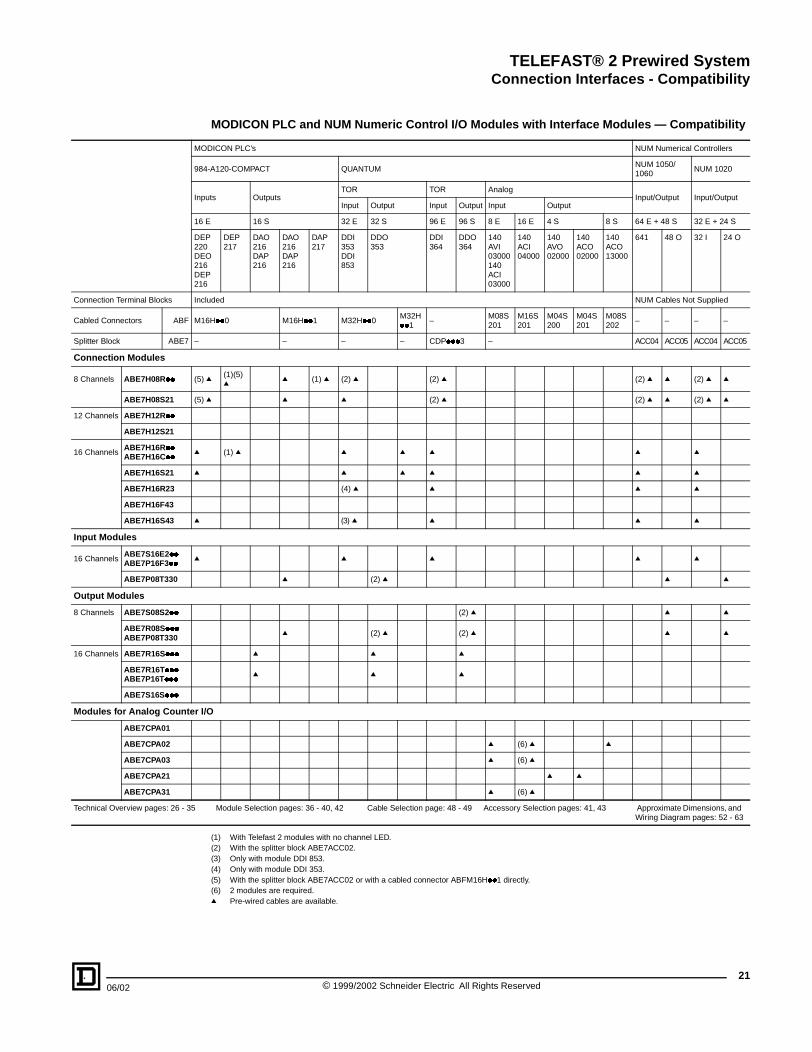
(1) With Telefast 2 modules with no channel LED.(2) With the splitter block ABE7ACC02.(3) Only with module DDI 853.(4) Only with module DDI 353.(5) With the splitter block ABE7ACC02 or with a cabled connector ABFM16H��1 directly.(6) 2 modules are required.q Pre-wired cables are available.
MODICON PLC and NUM Numeric Control I/O Modules with Interface Modules — Compatibility
ODICON PLC’s NUM Numerical Controllers
4-A120-COMPACT QUANTUMNUM 1050/1060
NUM 1020
puts OutputsTOR TOR Analog
Input/Output Input/OutputInput Output Input Output Input Output
E 16 S 32 E 32 S 96 E 96 S 8 E 16 E 4 S 8 S 64 E + 48 S 32 E + 24 S
EP0
EO6
EP6
DEP217
DAO216DAP216
DAO216DAP216
DAP217
DDI353DDI853
DDO353
DDI364
DDO364
140AVI03000140ACI03000
140ACI04000
140AVO02000
140ACO02000
140ACO13000
641 48 O 32 I 24 O
cluded NUM Cables Not Supplied
16H��0 M16H��1 M32H��0M32H��1
–M08S201
M16S201
M04S200
M04S201
M08S202
– – – –
– – – CDP���3 – ACC04 ACC05 ACC04 ACC05
) q (1)(5) q q (1) q (2) q (2) q (2) q q (2) q q
) q q q (2) q (2) q q (2) q q
(1) q q q q q q
q q q q q
(4) q q q q
(3) q q q q
q q q q
q (2) q q q
(2) q q q
q (2) q (2) q q q
q q q
q q q
I/O
q (6) q q
q (6) q
q q
q (6) q
Module Selection pages: 36 - 40, 42 Cable Selection page: 48 - 49 Accessory Selection pages: 41, 43 Approximate Dimensions, and Wiring Diagram pages: 52 - 63
21© 1999/2002 Schneider Electric All Rights Reserved

TELEFAST® 2 Prewired SystemConnection Interfaces - Compatibility
22
Technical Overview pages: 26 - 35
Connection Cables for ALLEN BRADLEY SLC500 PLC’s — Compatibility
1 For the SLC500 range, the specially designed cables connect to the I/O modules which are equipped with 40-way HE 10 connectors, integrating 32 channels.
2 Cables ABFH40H��� to connect 16-channel modules. They are supplied with one 40-way HE 10 connector, at the PLC end and 2 x 20-way HE 10 connectors, at the Telefast end. Available in 1.5 and 3 meter lengths, AWG 22, there are 2 types of “Y” form cables: one exclusively for inputs and one for outputs.
3 16-channel modules. It is possible to use 8-channel modules by inserting splitter block ABE7ACC02.
Connection Cables for SIEMENS S5 PLC’s — Compatibility
1 The 24 Vdc power supply may be provided via 6EP5-��� terminal blocks connected to the PLC modules.For the 95U/100U/115U/135U/155U ranges, manufacturers cables are connected to terminal blocks via 14-way HE 10 connectors (6EP5-���-1AA00). Each connector integrates 8 channels.
2 Cables ABFH28H��� to connect 16-channel modules. They are supplied with 2 x 14-way HE 10 connectors, at the S5 PLC end and one 20-way HE 10 connector, at the Telefast end. Available in 4.92 and 9.8 ft. (1.5 and 3 meter) lengths, AWG 26, these “Y” form cables only connect the I/O controlling the relay modules.
3 Cables ABFH14H��� to connect 16-channel modules. They are supplied with one 14-way HE 10 connector, at the S5 PLC end and one 20-way HE 10 connector, at the Telefast end. Available in 4.92 and 9.8 ft. (1.5 and 3 meter) lengths, AWG 26, these cables are used to connect the I/O directly to the modules.
(1) The 24 Vdc power supply is connected using Telefast modules only. The 0 Vdc connections must be of equal potential.(2) The power may be supplied via the PLC terminal block or the Telefast module.
Module Selection pages: 36 - 40, 42 Cable Selection page: 50 - 51 Accessory Selection pages: 41, 43 Approximate Dimensions, and Wiring Diagram pages: 52 - 63
1
2
3
3
01
23
45
67
89
1011
1213
1415
24 Vdc (2)
24 Vdc (2)
32 Channels
16 Channels
6 Channels
01
23
45
67
89
1011
1213
1415
1
3 2
5
4
24 Vdc (1)
24 Vdc (1)
8 Channels
8 Channels
Channels
© 1999/2002 Schneider Electric All Rights Reserved 06/02

TELEFAST® 2 Prewired SystemConnection Interfaces - Compatibility
06/02
Integral to the PLC’s
Connection Terminal Blocks
ConnectionModularity
Cables:16 Channels ABF
8 Channels ABF
(7) ABF
Connection Modules
8 Channels ABE7H08R��
ABE7H08S21
12 Channels
ABE7H12R��ABE7H12S21
16 Channels
ABE7H16R��ABE7H16C��
ABE7H16S21
ABE7H16R23
ABE7H16F43
ABE7H16S43
Input Modules
16 Channels
ABE7S16E2��
ABE7P16F3��
Output Modules
8 Channels ABE7S08S2��
ABE7R08S���
ABE7P08T330
16 ChannelABE7R16S���ABE7R16T���
ABE7P16T��� (6)
ABE7S16S���
Modules for Analog Counter
ABE7CPA01
ABE7CPA02
ABE7CPA03
ABE7CPA21
Technical Overview pages: 26 - 35
(1) With Telefast 2 modules with no channel LED.(2) With splitter block ABE7ACC02.(3) ABES16S2B2 module only.(4) Input only.(5) Power supply 24 Vdc without cable.(6) Do not use with ABE7ACC21/20.(7) Cable with 25-way SUB-D connector at Telefast end. Labelled bare wires at PLC end.q Pre-wired cables are available.
ALLEN BRADLEY and SIEMENS S5 PLC I/O Modules — Compatibility
ALLEN BRADLEY SIEMENS
SLC500 S5-95U/100U S5-115U S5-135U/155U
Input Output I/O Input Input OutputAnalog Input
Input Output Input OutputAnalog Input
Analog Output
32 I 16 I 16 O 32 O 16 I + 16 O 16 I 8 I 8 O 4 I 32 I 32 O 32 I 32 O 8 I 8 O
1746IB32
1746IB16
1746OB16
1746OB32
1746OV32
6ES5-0958MA036ES-5-4828MA13
6ES5-4228MA11
6ES5-4218MA126ES5-4318MA11
6ES5-4418MA116ES5-4548MA11
6ES5-4648ME11
6ES5- 4307LA126ES5-4207LA11
6ES5-4417LA126ES5- 4517LA116ES5-4517LA21
6ES5-4304UA146ES5-4204UA14
6ES5-4414UA146ES5- 4514UA14
6ES5-4604UA13
6ES5-4704UA12
None6EP5-100-1AA00
6EP5-100-1AA00
Included Included6ES5-700-8MA11
6EP5-115-1AA00
6EP5- 115-1AA00
6EP5-135-1AA00
6EP5-135-1AA00
6ES5-497-4UB12
6ES5-497-4UB12
H40H��0
R16H201
R16H200
H40H��1 H28H��0 H28H��0
H28H��0
H28H��0
H14H��0H14H��0
S16H��0
S16H��0
H14H��0
H14H��0
H14H��0
H14H��0
F25S200
F25S200
F25S200
(2) q (2) q (2) q(1) (2) q q q q q q q q q q
(2) q (2) q (2) q q q q q q q q q q
q q (5) q q (1) q (4) q q q q
q q q q (4) q q q q
q
q q q q q q
q q q q q q
(2) q q q q q
(2) q q q (2) q (2) q
q q q q q
q q q q
(3) q (3) q (3) q (3) q
I/O
q
q q
q
q
Module Selection pages: 36 - 40, 42 Cable Selection page: 50 - 51 Accessory Selection pages: 41, 43 Approximate Dimensions, and Wiring Diagram pages: 52 - 63
23© 1999/2002 Schneider Electric All Rights Reserved
TELEFAST® 2 Prewired SystemConnection Interfaces - Compatibility
24
Technical Overview pages: 26 - 35
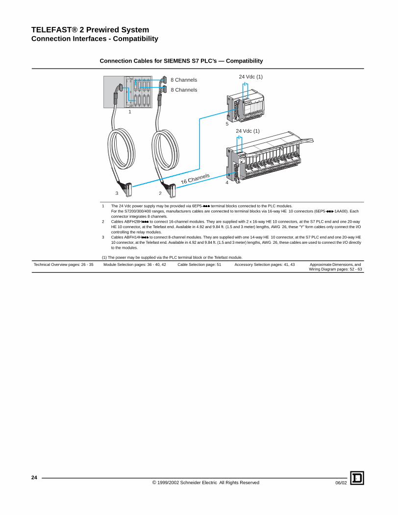
Connection Cables for SIEMENS S7 PLC’s — Compatibility
1 The 24 Vdc power supply may be provided via 6EP5-��� terminal blocks connected to the PLC modules.For the S7200/300/400 ranges, manufacturers cables are connected to terminal blocks via 16-way HE 10 connectors (6EP5-���-1AA00). Each connector integrates 8 channels.
2 Cables ABFH28H��� to connect 16-channel modules. They are supplied with 2 x 16-way HE 10 connectors, at the S7 PLC end and one 20-way HE 10 connector, at the Telefast end. Available in 4.92 and 9.84 ft. (1.5 and 3 meter) lengths, AWG 26, these “Y” form cables only connect the I/O controlling the relay modules.
3 Cables ABFH14H��� to connect 8-channel modules. They are supplied with one 14-way HE 10 connector, at the S7 PLC end and one 20-way HE 10 connector, at the Telefast end. Available in 4.92 and 9.84 ft. (1.5 and 3 meter) lengths, AWG 26, these cables are used to connect the I/O directly to the modules.
(1) The power may be supplied via the PLC terminal block or the Telefast module.
Module Selection pages: 36 - 40, 42 Cable Selection page: 51 Accessory Selection pages: 41, 43 Approximate Dimensions, and Wiring Diagram pages: 52 - 63
01
23
45
67
89
1011
1213
1415
1
3 2
5
4
24 Vdc (1)
24 Vdc (1)
8 Channels
8 Channels
Channels
© 1999/2002 Schneider Electric All Rights Reserved 06/02

TELEFAST® 2 Prewired SystemConnection Interfaces - Compatibility
06/02
Integral to the PLC’s 6ES7-
Connection Terminal Blocks 6ES7-
ConnectionModularity
Cables:16 Channels ABF
8 Channels ABF
Others ABF
Connection Modules
8 ChannelsABE7H08R��ABE7H08S21
12 Channels ABE7H12R��
ABE7H12S21
16 ChannelsABE7H16R��ABE7H32E���ABE7H16C��
ABE7H16S21
ABE7H16R23ABE7H16F43
ABE7H16S43
Input Adaptation Modules
16 ChannelsABE7S16E2��ABE7P16F3��
Output Adaptation Modules
8 Channels ABE7S08S2��
ABE7R08S���
ABE7P08T330
16 Channels ABE7R16S���
ABE7R16T���
ABE7P16T��� (6)
ABE7S16S���
Modules for Analog Counter
ABE7CPA01
ABE7CPA02
ABE7CPA03
ABE7CPA21
Technical Overview pages: 26 - 35
(1) With Telefast 2 modules with no channel LED.(2) With splitter block ABE7ACC02.(3) ABE7S16S2B2 module only.(4) Input only.(5) Power supply 24 Vdc without cable.(6) Do not use with ABE7ACC21 and ABE7ACC20.(7) Cable with 25-way SUB-D connector at Telefast end. Labelled bare wires at PLC end (see diagram on page 62).q Pre-wired cables are available.
SIEMENS S7 PLC I/O Modules — Compatibility
SIEMENS
S7-200 S7-300 S7-400
Input/Output Input Output Input Input Output OutputAnalog Output
Input OutputAnalog Input
Analog Output
14 I + 10 O 8 I 8 O 16 I 32 I 16 O 32 O 4 O 32 I 32 O 8 I 8 O
214-1ACO10XB0
221-1BF00-0XA0
222-1BF00-0XA0
321-1BH01-0AA0
321-1BL00-0AA0
322-1BH01-0AA0
322-1BL00-0AA0
332-5HD01-0AA0
421-1BL00-0AA0
442-1BL00-0AA0
431-1KF00-0AB0
432-1HF00-0AB0
Included Included Included921-3AB00-0AA0
921-3AA20-0AA0
921-3AB00-0AA0
921-3AA20-0AA0
392-1AJ00-0AA0
921-4AB00-0AA0
921-4AB00-0AA0
492-1AL00-0AA0
492-1AL00-0AA0
– – – H32H��0 H32H��0 H32H��0 H32H��0 – H32H��0 H32H��0 – –
– S08H��2 S08H��3 H16H��0 H16H��0 H16H��0 H16H��0 – H16H��0 H16H��0 – –
S24H200 – – – – – – – F25S200 (7) – – F25S200 (7) F25S200 (7)
q q q q q q q q
q
q
q q q q
q q q q
q q q
q q q
q q q q
q q (2) q (2) q
q q q
q q q q
q q q
q (3) q (3) q (3) q
I/O
q
q q
q
q
Module Selection pages: 36 - 40, 42 Cable Selection page: 51 Accessory Selection pages: 41, 43 Approximate Dimensions, and Wiring Diagram pages: 52 - 63
25© 1999/2002 Schneider Electric All Rights Reserved

TELEFAST® 2 Prewired SystemConnection Interfaces - Technical Overview
26
Relay for Modules ABE7�16T
Relay
Function
Modules
ABE7�16T210
ABE7�16T111/M111
ABE7�16T212
ABE7�16T214
ABE7�16T215
ABE7�16T230
ABE7�16T231
12.5 mm Wide Relays for Mod
Relay
Function
Modules
ABE7�16T318
ABE7�16T330
ABE7�16T332
ABE7�16T334
ABE7�16T370
ABE7P08T330
Approvals
Degree of Protection
Protective Treatment
Resistance to Incandescent Wire
Shock Resistance
Vibration Resistance
Resistance to Electrostatic Disch
Resistance to Radiated Fields
Resistance to Fast Transients
Resistance to Shockwaves
Ambient Air Temperature
Insulation Voltage (for 1 minute)
Installation Category
Degree of Pollution
Mounting
Cable c.s.a.Screw terminals
Tightening Torque
Compatibility pages: 14 - 25
Connection Interfaces - Technical Overview
(1) Product mounted on removable input modules ABE7P16F3ffk Can be replaced by a P or Rq Compatible
Modules with Removable Output Relays
fff Relay width 10 mm Relay width 5 mm
ABR7S21 ABR7S23 ABS7SA2M ABS7SC2E ABE7ACC20 ABR7S11 ABS7SC1B
Relay 1 N/O Relay 1 C/OOutput230 Vac - 0.5 A
Output48 Vdc - 0.5 A
Continuity 0.5 A Relay 1 N/OOutput24 Vdc - 2 A
q q q q q
q q
q q q q q
q q q q q
q q q q q
q q q q
q
ules ABE7�16T3ff
ABR7S33 ABR7S37 ABS7SA3M ABS7SC3E ABS7SC3BA ABE7ACC21 (1)
Relay 1 C/O Relay 2 C/OOutput230 Vac-1.5 A
Output48 Vdc-1.5 A
Output 24 Vdc-2AProtected
Continuity 0.5 A
q q q q
q q q q q
q q q q q
q q q q
q
q q q q q
General System Environment
UL File: E164866 CCN: NRAQCSA: File LR89150 Class 3211 07
Entire range of modules
LROS, BV, GL, DNV Modules with fixed screw terminal block only.
Conforming to IEC 60529 (against direct contact) IP 2X
“TC”
Conforming to IEC 60695-2-1 °C 750: extinguish time < 30 s
Conforming to IEC 60068-2-27 ms 11 (half sine wave), 15 g (acceleration)
Conforming to IEC 60068-2-6 Hz 10 to 150, 2 g (acceleration)
arge Conforming to IEC 61000-4-2 Level 3
Conforming to IEC 61000-4-3MHzV/m
26 to 1000-Level 310
Conforming to IEC 61000-4-4 Level 3
Conforming to IEC 61000-4-5 µs 1.2/50 - 8/20
For operation, conforming to IEC 61131-2For storage, conforming to IEC 61131-2
°F (°C)°F (°C)
23 to 140 (- 5 to + 60)-40 to +176 (- 40 to + 80)
Terminal/mounting rails kV 2
Conforming to IEC 60664 II
Conforming to IEC 60664 2
Standard rail 15 mm high � rail or solid plate with ABE7ACC01
1 conductor 2 conductors
Stranded wire without cable endmm2
AWG0.14 to 2.5 26 to 14
––
Stranded wire with cable endmm2
AWG0.09 to 1.5 28 to 16
0.09 to 0.7528 to 20
Solid wiremm2
AWG0.14 to 2.526 to 12
0.2 to 2.524 to14
Using 3.5 mm screwdriver bladelb-in (N�m)
5.4(0.6)
Module Selection pages: 36 - 40, 42 Cable and Accessary Selection page: 41, 43 - 51 Approximate Dimensions, and Wiring Diagram pages: 52 - 63
© 1999/2002 Schneider Electric All Rights Reserved 06/02

TELEFAST® 2 Prewired SystemConnection Interfaces - Technical Overview
06/02
General Characteristics
Type of Module
ABE7
Number of Channels
Function Input
Output
Input and Output
Channel and Power Supply Indication
Blown Fuse Indication
Power Supply Characteristic
Supply Voltage DC
Maximum Permissible Supply Current to Each Module DC
Voltage Drop on Power Supply Fuse DC
Protection Against Power Supply Overloads and Short-circuitsrequire quick-blow fuse (supplied)
Output Circuit Characteristic
Maximum Voltage Drop per Channel DC
Maximum Permissible Current per Channel DC
Maximum Permissible Current per Output Common DC
Current Drawn by Channel LED at Un DC
Permissible Leakage Current without Illuminating Channel LED (PLC I/O connected) DC
Opening of Circuit Isolators
Channel Fuse Protection(supplied with product)
Rated Insulation VoltageConforming to IEC 947-1Coil Circuit / Contact Circuit
Rated Impulse Withstand Voltage(1.2/50)
Compatibility pages: 14 - 25
(1) Compatible with MODICON TSX Micro and Premium PLC inputs only, for connection of 2-wire sensors, d.c.(2) If the modules are supplied with fuses (depending on model).
Passive Connection Modules for Discrete Signals and Removable Relay Modules, With and Without Relays
Passive connection module for discrete signal Removable relay modules
H20E���H32E���
H16C��H16CM
H16R��H16S21H16C31
H16R23 H16F43H16S43
H12R��H12S21
H08R��H08S21
R16T2��P16T2���16T111�16M111
R16T3��P08T330P16T3��
R16T370 P16F31�
16 16 16 16 16 12 8 16/8 16/8 16 16
� H16C � Type 2 (1) H16S43 � � – – – �
� H16C � – H16F43 � �
R16T2��P16T2���16T111
� � –
– H16CM�1 – – – – – �16M111 – – –
Via green LED (for products equipped with indication)
– Via red LED –
s (PLC end)
V 19 to 30 conforming to DIN 19240, IEC 1131 (Un = 24)
A 1.8 6.1 4.1 1
V 0.3 0.2 0.3
A 2F43:2S43:1
6.3 1
s
V –F43:2S43:0.1
– See relay characteristics on page 29.
mA 500 125 500 See temperature derating curves on page 32.
A 1.8 6.1 4.1 16 –
mA 3.2 10 3.2
mA 1.5 4 1.5
Under no load
A – 0.125 – 0.5 (2) 2 (2) –
V – 300
kV – 2.5
Module Selection pages: 36 - 40, 43 Cable and Accessory Selection pages: 41, 43 - 51 Approximate Dimensions, andWiring Diagram pages: 52 - 63
27© 1999/2002 Schneider Electric All Rights Reserved

TELEFAST® 2 Prewired SystemConnection Interfaces - Technical Overview
28
Type of Module and Relay
Control Circuit Characteristi
Rated Voltage Us DC
50/60 Hz AC
Max. Voltage (IEC 1131-2) DC
(including ripple) AC
Maximum Current (Ie) at Us DC
AC
State 1 Guaranteed DC
U ≥ …/I ≥ … AC
State 0 Guaranteed DC
U ≤ …/I ≤ … AC
Conforming to IEC 1131
External Protection
Removable Terminal Block
Output Circuit Characteristic
Rated Operational Voltage Ue DC
Minimum/maximum Voltage DC(IEC 1131-2)
Minimum/maximum Switching Current DC
Maximum Residual Current at State 0 DC
Maximum Voltage Drop at State 1 DC
Internal Protection
Power Supply Protection
Other Characteristics
Maximum Response 0 �1Time 1 �0
Maximum Switching RateDuty cycle 50%
Dielectric StrengthTo IEC 947-1 Between Input/output
Rated Impulse Withstand Voltage(1.2/50)To IEC 947-1 Input/output
Mechanical DurabilityIn millions of operating cycles
Compatibility pages: 14 - 25
(1) Electromechanical(2) Including bounce (max. 1.6 ms)
Solid State Input Modules with Soldered or Removable Input Relays
Modules with soldered solid state input relaysRemovable input relays
Solid state E.M. (1)
ABE7S16 ABS7 ABR7
E2B1 E2E1 E2E0 E2F0 E2M0 EC3AL EC3B2 EC3E2 EA3E5 EA3F5 EA3M5 S33E
– For mounting in ABE7P16F31��modules.
cs for 1 Channel (sensor end)
V 24 48 – – – 5 (TTL) 24 48 – – – 48
V – – 48 110/130 230/240 – – – 48 110/130 230/240 –
V 30 60 – – – 6 30 60 – – – 60
V – – 53 143 264 – – – 53 143 264 –
mA 12 13 – – – 15 15 15 – – – 13
mA – – 12 8.3 8 – – – 12 8.3 8 –
V/mA 15/2 30/6 – – – 3.75/4.5 11/6 30/6 – – – 34/8.2
V/mA – – 32/5 79/5 164/4.5 – – – 32/5 79/5 164/4.5 –
V/mA 5/2 10/2 – – – 2/0.09 5/2 10/2 – – – 3.6/0.8
V/mA – – 10/1.5 30/2 40/2 – – – 10/1.5 30/2 40/2 –
Type 1 Type 2 Type 1 Type 1 Type 1 – Type 2 Type 2 Type 1 Type 1 Type 1 –
Quick-blow fuse (sized according to sensors)
Yes No
s (PLC end)
V 24
V 19/30
mA 1/15
mA 0.1 –
V 1 –
Against short-circuits –
5 x 20 quick-blow fuse, 1 A
msms
0.050.4
2020
0.050.4
2020
13 (2)13 (2)
Hz 1000 25 1000 255 (no load) 0.5 (at le)
V 2000 (50/60 Hz) - 1 mm
kV 2.5
– 20
Module Selection pages: 36 - 40, 43 Cable and Accessory Selection pages: 41, 43 - 51 Approximate Dimensions, andWiring Diagram pages: 52 - 63
© 1999/2002 Schneider Electric All Rights Reserved 06/02

TELEFAST® 2 Prewired SystemConnection Interfaces - Technical Overview
06/02
Type of Module and Relay
Control Circuit Characteristic
Number of Channels
Rated Voltage Us D
Min/max Voltage (IEC 1131-2) D
Current per Channel at Us D(Channel + LED)
State 1 Guaranteed (2) D
State 0 Guaranteed D
Compatible with PLC Output (1) D
Power supply protection
Output Circuit Characteristic
Maximum Current per CommonScr
Switching Current per Channel (5
Rated Operational Voltage Ue
Maximum Voltage (IEC 1131-2)
Maximum Residual Voltage at In
Rated OperationalCurrent Ie≤ 140 ° F (60 °C)Maximum per Channel
DC
DC
AC
AC
D
Minimum Current per Channel
Maximum Residual Current
Faults Detected
Report of Fault Detected (4)
Switchable Inductive Energy L/R(without additional discharge device
Circuit-breaker Threshold
External Protection
Removable Terminal Block
Other Characteristics
Rated Insulation VoltageConforming to IEC 947-1
Maximum Response Time 0on Resistive Loads 1
Switching Frequencyon Inductive Loads
Rated Impulse Withstand Voltage
Compatibility pages: 14 - 25
(1) Only for use on PLC modules (output interfaces) with integral protection (auto-protected outputs).(2) On versions with LED indication.(3) With free-wheel diode on load, the DC13 value is equal to the value of DC12 x 0.9.(4) 940A fault on a module output Qn will set PLC output Qn to safety mode, which will be detected by the PLC.(5) See derating curves page 32.
Solid State Output Modules with Soldered or Removable Output Relays
Solid state output modules soldered Removable solid state output relays
ABE7S ABS7
��S2B0 (1) 16S1B2 08S2B1 (1) SC1B SC2E SA2M SC3BA SC3E SA3M
– – For module ABE7�16T21� For mounting on module ABE7�16T3��
s for 1 Channel (PLC end)
8 or 16 16 8 – – – – – –
C V 24
C V 19/30
CmA 4.5 (including LED) 7 + 3.2 4 + 3.2 9 + 3.2 4 + 3.2 4 + 3.2 9 + 3.2
C V 16.9 16 18.6
mA 3.1 5.5 2.9 6.5 2.9 2.9 6.5
C V 3.4 10 3.8 2.8 3.8 3.8 2.8
mA 0.4
C mA ≤ 100 – ≤ 500 All types of output
2 A quick-blow fuse See module characteristics page 27.
s (pre-actuator end)
ew A 8 dc 9 dc 10 dc 12 16 dc 16 ac 16 dc 16 dc 16 ac
) A 0.5 dc 0.7 dc 2 dc 2 dc 0.5 dc 0.5 ac 2 dc 1.5 dc 1.5 ac
V 24 24 dc 5-48 dc 24/240 ac 24 dc 5 to 48 dc 24 to 240 ac
V 30 30 dc 57.6 dc 264 ac 30 dc 60 dc 264 ac
V 0.6 0.3 0.5 0.12 dc 1 dc 1.1 ac 0.3 1.3 dc 1.3 ac
12 A 0.5 0.7 2 2 0.5 – 2 1.5 –
13 A 0.5 0.7 1 (3) 2 0.5 – 2 1.5 –
12 A – – – – – 0.5 – – 1.5
14 A – – – – – 0.5 – – 0.7
C6 W 10 – – 10 – 10 – –
mA 1 1 dc 1 dc 10 ac 10 dc 1 dc 10 ac
mA 0.3 0.5 0.1 0.5 dc 2 ac 2 dc 0.3 dc 2 ac
Auto-protectedOverload and short-circuit
– – –Auto-protected Overload & short-circuit
– –
Yes No Yes No
)ms ≤ 400/(U.I) ≤ 1700/(U.I) 2 (U.I) – –
(U.I)≤ 1700/ – –
A ≥ 0.75 ≥ 2.6 – – – 2.5 – –
By adjustable quick-blow fuse
Yes No
V Not insulated 300
�1 �0
msms
0.10.02
0.20.1
0.10.02
0.010.4
0.10.6
1010
0.20.1
0.10.6
1010
Hz < 0.6/ LI2 < 0.5/ LI2 300
V – 2.5 –
Module Selection pages: 36 - 40, 42 Cable and Accessory Selection pages: 41, 43 - 51 Approximate Dimensions, andWiring Diagram pages: 52 - 63
29© 1999/2002 Schneider Electric All Rights Reserved

TELEFAST® 2 Prewired SystemConnection Interfaces - Technical Overview
30
Type of Module and Relay
Control Circuit Characteristi
Rated Voltage Us
Tripping Threshold at 104 °F (40 °
Drop-out Voltage at 69 °F (20 °C)
Maximum Operational Voltage
Maximum Current at Us per Chan
Drop-out Current at 68 °F (20 °C)
Maximum Dissipated Power at Us
Loss of Voltage
Power Supply Protection
Contact Characteristics (pre-
Contact Composition
Maximum Switching Voltage
Frequency of Operational Curren
Number of Channels per Commo
Maximum Current per Channel (limited by module)
Maximum Current per CommonScrew
Relay Maximum Current (Ith)
Current for 500, 000 Operating Cycles
Minimum Switching Current
Short-circuit Protection
Fuse Fitted as Standard/channel
Low Level Contact Reliability Number of Faults
Removable Terminal Block
Other Characteristics (at amb
Maximum Operating Time at Us (including bounce)
Maximum Bounce Time
Maximum Operating Rate
Mechanical Durability
Dielectric StrengthCoil circuit/contact circuit
Rated Impulse Withstand Voltage(1.2/50)
Compatibility pages: 14 - 25
(1) LatchingEM = Electromechanical
Electromechanical Output Relay Modules with Soldered or Removable Electromechanical Output Relays
E.M. output relay moduleswith soldered relays
Removable electromechanical output relays
ABE7 ABR7
R��S111 R��S21� R08S216 S21 S23 S33 S37 S11
– –
For mounting on ABE7 modules
P16T21�R16T21�
P16T23� P16T3��R16T3��
R16T370�16T111�16M111
cs for 1 Channel (PLC end)
Vdc 24
C) Vdc 19.2 19.7 19.2 (1) 19.7 16.8 16.8
Vdc 2.4 – 2.4 3.6 2
Vdc 30
nel Coil + LED mA 9 + 3.2 15 + 3.2 12.5 + 3.2 15 + 3.2 25 + 3.2 7 + 3.2
mA 0.5 1 – 1 3.5 0.5
W 0.22 0.36 0.3 0.36 0.6 0.170
Max. time not affecting the hold ms 5 3 5 1
1A quick-blow fuse
actuator side, at ambient temperature of 68 °F (20 °C)
1N/O 1N/O 1N/O 1N/O 1C/O 1C/O 2C/O 1N/O
To IEC 60947-5-1VacVdc
25030
380220
250130
264130
25030
t Hz 50/60
n 4 (08S111)8 (16S111)
8Volt-free
8 4 4
Volt-freeWith common
AA
–2
54
2 A–
54
54
55
5–
53
A 12 10 – 16 16 12 12
A 2 5 5 5 5 10 8 6
24 V DC 12 A 0.6 1.5 2 1.5 1.2 3 2.5 3
24 V L/R = 10 ms DC 13 A 0.2 0.6 1.5 0.6 0.45 1.4 1 0.5
230 V AC 12 A 0.6 1.5 2 1.5 1.2 3 2.5 2
230 V AC 15 A 0.4 0.9 1 0.9 0.7 1.7 1.3 0.4
At 5 V minimum voltage mA 1 10 2 10 100 100
For Ik < 1 kA (AC) and < 100 A (DC) High breaking capacity fuse
A – – 0.5 2 –
(1/n million operating cycles)17 V/5 mA1/100
10 V/2 mA1/2
17 V/10 mA1/100
1/100Not available
Yes No
ient temperature of 68 °F (20 °C)
Between energizing the coil and closing of the N/O contact
ms 10 5 10 13 15 5
Between de-energizing the coil and opening of the N/O contact
ms 6 5 4 5 13 20 2.5
N/O contact ms 5 2 5 1.6 4 1.5
N/C contact ms – – – 7.5 5.5 7.5 –
No load 10 Hz 180/min 10 Hz 5 Hz 1200/min
At le 0.5 Hz 30/min 0.5 Hz 6/min
In millions of operating cycles 20 20 20 20
Conforming to IEC 60947-1 V 2000 (50/60 Hz) - 1 mm 4
Conforming to IEC 60947-1 kV 2.5 5 2.5 6
Module Selection pages: 36 - 40, 42 Cable and Accessory Selection pages: 41, 43 - 51 Approximate Dimensions, andWiring Diagram pages: 52 - 63
© 1999/2002 Schneider Electric All Rights Reserved 06/02

TELEFAST® 2 Prewired SystemConnection Interfaces - Technical Overview
06/02
General CharacteristicsType of Accessory
Description
Number of Channels
Type of ConnectorNumber of ways at PLC end
Type of ConnectorNumber of ways at Operative part e
Min/max Connectable c.s.a.
Min/max Cable Diameter
Type of Terminal Block
Protection Index
Rated Voltage Us
Maximum Current at Us per Chan
Maximum Supply Current at Us
Switching Capacity
Circuit-breaker Threshold
General Characteristics (conType of Module
Description
Number of Channels
Protection Index
Power Supply
Automatic Limitation Per Channe
Maximum Consumption
Operating Temperature
Dielectric Strength, Channel/grou
Isolation Between Channels
Logic
Compatibility with Encoder Outp
Low Input Voltage (VIL)
High Input Voltage (VIH)
Connection, Process Side
Connection, PLC Side
Overvoltage Protection on Curren
Current Loop Continuity
Maximum Overvoltage on Inputs
Maximum Current on Inputs
Standards
Permissible Common Mode VoltaBetween Channels
Permissible Common Mode VoltaBetween Channel and Ground
Maximum Current on Integrated C
Rated Voltage Us
Compatibility pages: 14 - 25
(1) See module compatibility, page 26.(2) 1 channel for TSX CTZ1A, 2 for TSX CTZ2A�, 8 for TSX 37 22(3) CJC: Cold Junction Compensation(4) Positive: U < 2.4 V 0L, U > 3.9 V 1L; Negative: U < 2.4 V 1L, U > 3.9 V 0L(5) Add BG standard for ABE7CPA13
Accessories, Analog Modules
ABE7 ACC02 ACC20 (1) ACC21 (1) ACC80 ACC81 ACC82 ACC83 BV10 BV20
Splitter module
Removable continuity blocks with internal fuse
Enclosure feedthroughAdditional clip-in terminal block
16/2 x 8 1 1 32/2 x 16 32/2 x 16 16 8 or 12 8 16
1 x HE 10 20-way
– –2 x HE 10 20-way
–1 x HE 10 20-way
1 x HE 10 20-way
–
nd2 x HE 10-way
– –Industrial 40-way Cylind. M23 CNOMO
19-way, female–
Male Female
mm2 – – – 0.75/2.5 0.5/1.5 0.75/2.5 0.14/2.5
mm – – – – 10 to 19 – –
– – –Spring or screw
Spring or screw
Spring or screw
Spring or screw
Screw Screw
IP20 IP 20 IP 20 IP 65 IP 65 IP 65 IP 65 IP 65 IP 65
V 24 24 24 24 24 24 24 24 24
nel A 0.5 – – 0.5 0.5 0.5 0.5 0.5 0.5
A 2 – –4(2 X HE10)
4 2 6 16 16
A – 0.5 –
V – 0.5 –
tinued)ABE7 CPA01 CPA11 CPA12 CPA02 CPA21 CPA03 CPA31 CPA13 TES 160
Analog counter
Counter/motion
Thermo-couple
Analog signal connection module SafetySimulation and forcing module
(2) 1
16 (Telefast CJC made) (3) 14 (external CJC made)
8 passive connection point to point
4 passive connection point to point
8 sensor supply distribution
8 isolated, Isolated sensor supply distribution
12 double contact emergency stops
16
IP 20
V –11 to305
– – – 24 IEC24 IEC isolated dc/dc
24 IEC -20 + 25%
–
l mA – – – – – 25 – –
mA – 130 – – – 300 – –
°F (°C)0° to 140°(0 to 60)
–14° to 140°(-10 to + 60)
–
nd V – 1000 – – – 1000 700 –
V – – – – – 1000 – –
Positive or negative (4) – – – – – – –
ut
Totem-pole10 to 30 V5 VdcRS422
Totem-pole 11 to 30 VTTL 5 Vtransistors open collectors 11 to 30 V
– – – – – – –
V – 0< VIL < 24 – – – – – – –
V – 3.9 < VIH < 30 – – – – – – –
Fixed screw terminal blockRemovable screw term.
Fixed screw term.
–
SUB D 15-way female
SUB D 15-way male
2 x SUB D 25-way male
1 x SUB D, 25-way male1 x SUB D 50-way
1 x HE 1020-way and screw term.
t Inputs – – – – – Zener 8.5 V – –
– – – – – Zener 8.5 V – –
V – – – – – ± 30 – –
mA – – – – – ± 30 – –
– – – – – IEC 61131, CSA22 2, UL 508 (5)
ge V – – 250 – – – – – –
ge V – – 250 – – – – – –
ommons A – – – – – – – – 2
V – – – – – – – – 24
Module Selection pages: 36 - 40, 42 Cable and Accessory Selection pages: 41, 43 - 51 Approximate Dimensions, andWiring Diagram pages: 52 - 63
31© 1999/2002 Schneider Electric All Rights Reserved

TELEFAST® 2 Prewired SystemConnection Interfaces - Technical Overview
32
Calculation Curves to Determ8-channel module
1 TSX CDP��2 and ABFH20H��0 2 TSX CDP��3 cables with 0.34 mm
Temperature Derating CurveABE7R��S111 Curve 1ABE7R1��S212 Curve 2
ABE7�16T21� Curve 1ABE7P16T334 Curve 2
ABE7R16T370
ABS7SC3BA
100% of channels u50% of channels
Compatibility pages: 14 - 25
00,00,51,01,52,02,53,03,54,04,55,0
205
1
2
15 25 310
3
Tota
l cur
rent
per
mod
ule
(A)
5 A
2 A
302010
1
2
5 A
4 A
2 A
302010
5 A
2 A
302010
2 A
302010
(1) The curves are given for a voltage drop of 1 V in the cable. For n volts tolerance, multiply the length determined from the graph by n.(2) There is no derating for ABE7S08S2B1, ABE7S��S2B0, ABE7S16S2B2 output modules, or for ABS7EC��� and ABE7EA��� solid state input relays
ine the Cable and its Length According to the Current (1)12-channel module 16-channel module
cables with 0.08 mm2 c.s.a. (AWG 28) 3 Cables with 0.13 mm2 c.s.a. (AWG 26)2 c.s.a. (AWG 22)
s for Modules and Removable Relays (2)
ABE7P16T214 ABE7P16T215, ABE7P16T23�
ABE7�16T332, ABE7P16T318 ABE7�16T330
ABS7SC1B ABE7SA2M
ABS7SC2E Curve 1 +ABS-7SC3E Curve 22 ABS7SA3M
ses
Module and Relay Selection pages: 36, 42 Cable Selection pages: 43 - 51 Approximate Dimensions, andWiring Diagram pages: 52 - 63
250
500
50 m450 4035 Ave
rage
cur
rent
per
cha
nnel
(m
A)
00,0
1,0
2,0
3,0
4,0
250
500
5,0
6,0
7,0
50 m205
1
2
4515 25 30 403510
3
Tota
l cur
rent
per
mod
ule
(A)
Ave
rage
cur
rent
per
cha
nnel
(m
A)
00,0
0,5
1,0
1,5
2,0
25
50
75
100
50 m205
1
2
4515 25 30 403510
3
Tota
l cur
rent
per
mod
ule
(A)
Ave
rage
cur
rent
per
cha
nnel
(m
A)
5040
2 A
4 A
5040302010
5 A
2 A
60 °C5040302010
5040
1
2
5 A
2 A
5040302010
5 A
2 A
5040302010
5040
1 A
2 A
0,5 A
1,5 A
5040302010
0,5 A
0,2 A
5040302010
5040
1 A
0,5 A
1,5 A
60 °C5040302010
2
1
1,5 A
1 A
5040302010
© 1999/2002 Schneider Electric All Rights Reserved 06/02

TELEFAST® 2 Prewired SystemConnection Interfaces - Technical Overview
06/02
Compatibility pages: 14 - 25
Note:The products durability on this page are based on average usage and normal operating conditions. Actual life will vary with conditions. The above statements are not intended to, nor shall they create any expressed or implied warranties as to product operation or life. For information on the listed warranty offered on this product, refer to the Square D terms and conditions of sale found in the Square D Digest.
Electrical Durability (in millions of operating cycles) (conforming to IEC 60947-5-1)ABE7R��S111d.c. loadsDC12 curves (1)
Current (A)
ABE7R��S2��, ABR7S2� (6), ABE7R16T2��
Current (A)
DC 13 curves (2)
Current (A) Current (A)
a.c. loadsAC 12 curves (3)
Current (A) Current (A)
AC 14 curves (4)
Current (A) Current (A)
AC 15 curves (5)
Current (A) Current (A)
(1) DC12: control of resistive loads and of solid state loads isolated by optocoupler, l/R ≤ 1 ms(2) DC13: control of electromagnets, L/R ≤ 2 x (Ue x Ie) in ms, Ue: rated operational voltage, Ie: rated operational current (with a protective diode on
the load, DC12 curves must be used with a coefficient of 0.9 applied to the number in millions of operating cycles).(3) AC12: control of resistive loads and of solid state loads isolated by optocoupler, cos ϕ ≥ 0.9(4) AC14: control of small electromagnetic loads ≤ 72 VA, make: cos ϕ = 0.3, break: cos ϕ = 0.3(5) AC15: control of electromagnetic loads > 72 VA, make: cos ϕ = 0.7, break: cos = 0.4(6) Multiply all durability values by 0.75 for ABS7S23 and for ABR7S37
Module and Relay Selection pages: 36 - 42 Cable and Accessory Selection pages: 41, 43 - 51 Approximate Dimensions, andWiring Diagram pages: 52 - 63
00,00,10,20,3
1,00,90,80,70,60,50,4
21 1,50,5
24V
48V
0 1,51 20,50,0
0,5
1,0
1,5
2,0
2,5
3,0
24V
48V
00,00,10,20,3
1,00,90,80,70,60,50,4
10,4 0,60,2 0,8
L/R = 10ms 24V
L/R = 10ms 48V
L/R = 60ms 48V
L/R = 60ms 24V
0,1 0,3 0,5 0,7 0,9 10,2 0,4 0,6 0,80,0
1,4
1,2
1,0
0,8
0,6
0,4
0,2
L/R = 10ms 24VL/R = 10ms 48V
L/R = 60ms 48V
L/R = 60ms 24V
00,00
0,25
1,50
1,25
1,00
0,75
0,50
21 1,50,5
24V
48V
110V
230V
0 0,5 1,5 2,5 3,5 4,51,0 2,0 3,0 4,0 50,0
0,5
1,0
1,5
2,0
2,5
3,0
24V
48V
110V230V
0 0,80,4 10,60,20,00,20,40,60,81,01,21,41,61,82,0
230V
110V
24V48V
0 0,2 0,6 1,0 1,4 1,80,4 0,8 1,2 1,6 20,0
0,5
1,0
1,5
2,0
2,5
24V48V
110V
230V
0,25 1,751,500,75 1 21,250,500,000,050,100,150,200,250,300,350,400,450,50
110V
48V
230V
0,5 0,90,7 1,31,1 1,71,5 1,90,00,10,20,30,40,50,60,70,80,91,0
230V
48V
110V
33© 1999/2002 Schneider Electric All Rights Reserved

TELEFAST® 2 Prewired SystemConnection Interfaces - Technical Overview
34
Compatibility pages: 14 - 25
Electrical Durability (in millions of operating cycles) (conforming to IEC 60947-5-1)ABR7S3� (1), ABE7P16T3�� and ABE7R16T3��d.c. loadsDC12 curves (2)
Current (A)
DC 13 curves (3)
Current (A)
a.c. loadsAC 12 curves (4)
Current (A)
AC 14 curves (5)
Current (A)
AC 15 curves (6)
Current (A)
(1) Multiply all the durability values by 0.75 for ABS7S23 and for ABR7S37(2) DC12: control of resistive loads and of solid state loads isolated by optocoupler, l/R ≤ 1 ms(3) DC13: control of electromagnets, L/R ≤ 2 x (Ue x Ie) in ms, Ue: rated operational voltage, Ie: rated operational current (with a protective diode on
the load, DC12 curves must be used with a coefficient of 0.9 applied to the number in millions of operating cycles).(4) AC12: control of resistive loads and of solid state loads isolated by optocoupler, cos ϕ ≥ 0.9(5) AC14: control of small electromagnetic loads ≤ 72 VA, make: cos ϕ = 0.3, break: cos ϕ = 0.3(6) AC15: control of electromagnetic loads > 72 VA, make: cos ϕ = 0.7, break: cos ϕ = 0.4
Module and Relay Selection pages: 36 - 42 Cable and Accessory Selection pages: 41, 43 - 51 Approximate Dimensions, andWiring Diagram pages: 52 - 63
0 4,50,5 2,5 41 3,51,5 32 50,0
0,5
1,0
1,5
2,0
2,5
3,0
24V
48V
0 20,5 1,51 2,50,000,250,500,751,001,251,501,752,00
L/R = 60ms 48VL/R = 60ms 24V
L/R = 7ms 48V
L/R = 7ms 24V
0 41 32 53,50,5 2,51,5 4,50,0
0,5
1,0
1,5
2,0
2,5
3,0
48V
110V
230V
24V
0 0,1 0,3 0,5 0,7 0,90,2 0,4 0,6 0,8 10,0
0,5
1,0
1,5
2,0
2,5
48V
24V
110V230V
Note:The products durability on this page are based on average usage and normal operating conditions. Actual life will vary with conditions. The above statements are not intended to, nor shall they create any expressed or implied warranties as to product operation or life. For information on the listed warranty offered on this product, refer to the Square D terms and conditions of sale found in the Square D Digest.0 41 32 53,50,5 2,51,5 4,5
0,00
0,25
0,50
0,75
1,00
1,25
1,50
110V
48V24V
230V
© 1999/2002 Schneider Electric All Rights Reserved 06/02

TELEFAST® 2 Prewired SystemConnection Interfaces - Technical Overview
06/02
Compatibility pages: 14 - 25
Note:The products durability on this page are based on average usage and normal operating conditions. Actual life will vary with conditions. The above statements are not intended to, nor shall they create any expressed or implied warranties as to product operation or life. For information on the listed warranty offered on this product, refer to the Square D terms and conditions of sale found in the Square D Digest.
Electrical Durability (in millions of operating cycles) (conforming to IEC 60947-5-1)ABE7R16 111d.c. loadsDC12 curves (1)
Current (A)
ABE7R08S216
Current (A)Resistive loadsInductive loads
DC 13 curves (2)
Current (A)
a.c. loadsAC 12 curves (3)
Current (A) Current (A)Resistive loadsInductive loads
AC 15 curves x(4)
Current (A)
(1) DC12: control of resistive loads and of solid state loads isolated by optocoupler, l/R ≤ 1 ms(2) DC13: control of electromagnets, L/R ≤ 2 x (Ue x Ie) in ms, Ue: rated operational voltage, Ie: rated operational current (with a protective diode on
the load, DC12 curves must be used with a coefficient of 0.9 applied to the number in millions of operating cycles).(3) AC12: control of resistive loads and of solid state loads isolated by optocoupler, cos ϕ ≥ 0.9(4) AC15: Control of electromagnetic loads > 72 VA, make: cos = ϕ 0.7, break: cos ϕ = 0.4
Module Selection pages: 36 - 40, 42 Cable and Accessory Selection pages: 41, 43 - 51 Approximate Dimensions, andWiring Diagram pages: 52 - 63
0 1,0 2,0 3,0 4,0 6,05,0 7,00,00
0,25
0,50
0,75
1,00
1,25
1,50
24V
00,00
0,25
1,50
1,25
1,00
0,75
0,50
21 1,50,5
24VDC
24VDC
L/R = 7ms
0 1,0 2,0 3,0 4,00,00
0,05
0,10
0,15
0,20
0,25
0,30
24V
0 1,0 2,0 3,0 4,0 6,05,0 7,00,00
0,25
0,50
0,75
1,00
1,25
1,50
230V
00,00
0,25
1,50
1,25
1,00
0,75
0,50
21 1,50,5
230VAC
230VAC
0 1,0 2,0 3,0 4,00,000
0,025
0,050
0,075
0,100
0,125
0,150
230V
35© 1999/2002 Schneider Electric All Rights Reserved

TELEFAST® 2 Prewired SystemConnection Interfaces - Product Selection
36
Compatibility pages: 14 - 25
ABE-7H20E���
ABE7H16C21
Product Selection
(1) 8 I + 8 Q: these products have 2 common connections which enable inputs and outputs to be connected to the same module at the same time.
Passive Connection Modules for Discrete Signals
“Low Cost” Modules
Function No. of Channels
No. of Terminals
For PLC’sLength of PLC Connection Cable
Ft. (Meters)
Type of Connection Catalog Number Weight
lb (kg)per channel
on row number
Input or Output 16 1 2MODICON TSX Micro/Premium
3.28 (1) Screw ABE7H20E100 0.73 (0.330)
6.56 (2) Screw ABE7H20E200 0.90 (0.410)
9.84 (3) Screw ABE7H20E300 1.06 (0.480)
SIEMENS S7 4.92 (1.5) Screw ABE7H32E150 0.79 (0.360)
9.84 (3) Screw ABE7H32E300 1.01 (0.460)
“Miniature” Modules
FunctionNo. of Channels
No. of Terminals
LED per Channel
Polarity Distribution
Type of Connection Catalog Number
Weight lb (kg)
per channel
on row number
Input or Output 16 1 1 No No Screw ABE7H16C10 0.35 (0.160)
Yes No Screw ABE7H16C11 0.35 (0.160)
2 2 Yes 0 or 24 V Screw ABE7H16C21 0.45 (0.205)
3 3 Yes 0 or 24 V Screw ABE7H16C31 0.57 (0.260)
Input or Output 16 1 1 Yes No Screw ABE7H16CM11 0.35 (0.160)
2 2 Yes 0 or 24 V Screw ABE7H16CM21 0.44 (0.200)
Technical Overview pages: 26 - 35 Cable and Accessory Selection pages: 43 - 51 Approximate Dimension page: 52Wiring Diagram page: 55
© 1999/2002 Schneider Electric All Rights Reserved 06/02

TELEFAST® 2 Prewired SystemConnection Interfaces - Product Selection
06/02
Compatibility pages: 14 - 25
ABE7H16R50
ABE7H16R31
ABE7H16�43
(1) For MODICON TSX Micro, Premium and Numerical Controller NUM 1020/1060.(2) With LED to indicate blown fuse.
Passive Connection Modules for Discrete Signals (continued)
Function No. of Channels
No. of Terminals
LED per Channel
Polarity Distribution
Isolator (I) Fuse (F) per Channel
Type of Connection Catalog Number Weight
lb (kg)per channel
on row number
Input or Output 8 1 1 No No – Screw ABE7H08R10 0.41 (0.187)
Yes No – Screw ABE7H08R11 0.41 (0.187)
2 2 Yes 0 or 24 V – Screw ABE7H08R21 0.48 (0.218)
I Screw ABE7H08S21 0.54 (0.245)
12 1 1 No No – Screw ABE7H12R10 0.60 (0.274)
Yes No – Screw ABE7H12R11 0.60 (0.274)
2 No No – Screw ABE7H12R50 0.43 (0.196)
2 2 No 0 or 24 V – Screw ABE7H12R20 0.66 (0.300)
Yes o or 24 V – Screw ABE7H12R21 0.66 (0.300)
I Screw ABE7H12S21 0.83 (0.375)
16 1 1 No No – Screw ABE7H16R10 0.60 (0.274)
Yes No – Screw ABE7H16R11 0.60 (0.274)
2 No No – Screw ABE7H16R50 0.43 (0.196)
2 2 No 0 or 24 V – Screw ABE7H16R20 0.66 (0.300)
Yes 0 or 24 V – Screw ABE7H16R21 0.66 (0.300)
I Screw ABE7H16S21 0.83 (0.375)
3 3 No 0 and 24 V – Screw ABE7H16R30 0.76 (0.346)
Yes 0 and 24 V – Screw ABE7H16R31 0.76 (0.346)
Type 2 Input (1) 16 2 2 Yes 0 and 24 V – Screw ABE7H16R23 0.71 (0.320)
Input 16 2 1 Yes 24 V I, F (2) Screw ABE7H16S43 1.41 (0.640)
Output 16 2 1 Yes 0 V I, F (2) Screw ABE7H16F43 1.41 (0.640)
Technical Overview pages: 26 - 35 Cable and Accessory Selection pages: 41, 43 - 51 Approximate Dimension page: 52Wiring Diagram page: 54 - 55
37© 1999/2002 Schneider Electric All Rights Reserved
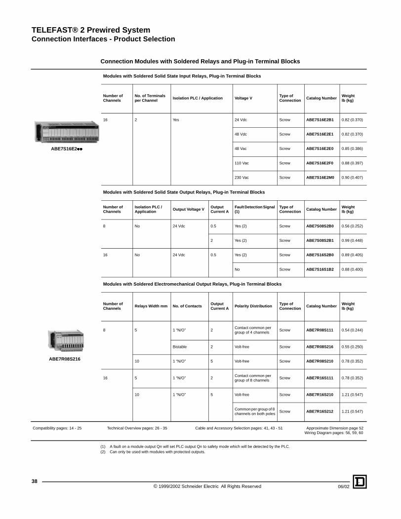
TELEFAST® 2 Prewired SystemConnection Interfaces - Product Selection
38
Compatibility pages: 14 - 25
ABE7S16E2��
ABE7R08S216
(1) A fault on a module output Qn will set PLC output Qn to safety mode which will be detected by the PLC.(2) Can only be used with modules with protected outputs.
Connection Modules with Soldered Relays and Plug-in Terminal Blocks
Modules with Soldered Solid State Input Relays, Plug-in Terminal Blocks
Number of Channels
No. of Terminals per Channel Isolation PLC / Application Voltage V
Type of Connection Catalog Number
Weight lb (kg)
16 2 Yes 24 Vdc Screw ABE7S16E2B1 0.82 (0.370)
48 Vdc Screw ABE7S16E2E1 0.82 (0.370)
48 Vac Screw ABE7S16E2E0 0.85 (0.386)
110 Vac Screw ABE7S16E2F0 0.88 (0.397)
230 Vac Screw ABE7S16E2M0 0.90 (0.407)
Modules with Soldered Solid State Output Relays, Plug-in Terminal Blocks
Number of Channels
Isolation PLC / Application Output Voltage V Output
Current AFault Detection Signal (1)
Type of Connection Catalog Number Weight
lb (kg)
8 No 24 Vdc 0.5 Yes (2) Screw ABE7S08S2B0 0.56 (0.252)
2 Yes (2) Screw ABE7S08S2B1 0.99 (0.448)
16 No 24 Vdc 0.5 Yes (2) Screw ABE7S16S2B0 0.89 (0.405)
No Screw ABE7S16S1B2 0.88 (0.400)
Modules with Soldered Electromechanical Output Relays, Plug-in Terminal Blocks
Number of Channels
Relays Width mm No. of Contacts Output Current A
Polarity Distribution Type of Connection
Catalog Number Weight lb (kg)
8 5 1 “N/O” 2Contact common per group of 4 channels
Screw ABE7R08S111 0.54 (0.244)
Bistable 2 Volt-free Screw ABE7R08S216 0.55 (0.250)
10 1 “N/O” 5 Volt-free Screw ABE7R08S210 0.78 (0.352)
16 5 1 “N/O” 2Contact common per group of 8 channels
Screw ABE7R16S111 0.78 (0.352)
10 1 “N/O” 5 Volt-free Screw ABE7R16S210 1.21 (0.547)
Common per group of 8 channels on both poles
Screw ABE7R16S212 1.21 (0.547)
Technical Overview pages: 26 - 35 Cable and Accessory Selection pages: 41, 43 - 51 Approximate Dimension page 52Wiring Diagram pages: 56, 59, 60
© 1999/2002 Schneider Electric All Rights Reserved 06/02

TELEFAST® 2 Prewired SystemConnection Interfaces - Product Selection
06/02
Compatibility pages: 14 - 25
ABE7R16T210
ABE7R16M111
(1) Not supplied with relays(2) Both technologies (electromechanical and solid state) may be combined on the same module.(3) 2 connection methods are available, enabling inputs and outputs to be connected to the same module at the same time.(4) Per group of 8 channels.(5) Per group of 4 channels.
Plug-in Relay Modules
Modules for Plug-in Solid State Input Relays (1)
No. of Channels
Terminals / Channel
For Relay Type
Isolation PLC / Application Input Connection Type of
Connection Catalog Number Weight lb (kg)
16 2ABS7EABR7
Yes Volt-free Screw ABE7P16F310 1.87 (0.850)
Polarity Distribution Screw ABE7P16F312 1.87 (0.850)
Output Modules Supplied with Plug-in Electromechanical Relays (2)
No. of Channels
Relay Width mm Type of Relay
No. and Type of Contacts Polarity Distribution / Application Catalog Number
Weight lb (kg)
16 5 ABR7S11 1 N/O Contact Common per Group of 4 Channels ABE7R16T111 1.32 (0.600)
Contact Common per Group of 4 Output Channels + 2 Input Common Terminals
ABE7R16M111 (3) 1.32 (0.600)
10 ABR7S21 1 N/O Volt-free ABE7R16T210 1.62 (0.735)
Common on Both Poles (4) ABE7R16T212 1.61 (0.730)
ABR7S23 1 C/O Contact Common (4) ABE7R16T231 1.61 (0.730)
Volt-free ABE7R16T230 1.71 (0.775)
12 ABR7S33 1 C/O Volt-free ABE7R16T330 2.87 (1.300)
Common on Both Poles (5) ABE7R16T332 2.65 (1.200)
ABR7S37 2 C/O Volt-free ABE7R16T370 2.87 (1.300)
Technical Overview pages: 26 - 35 Cable and Accessory Selection pages: 41, 43 - 51 Approximate Dimension page 52Wiring Diagram pages: 57 - 59
39© 1999/2002 Schneider Electric All Rights Reserved

TELEFAST® 2 Prewired SystemConnection Interfaces - Product Selection
40
Compatibility pages: 14 - 25
ABE7P16T2��
(1) Not supplied with relays(2) 2 connection methods are available, enabling inputs and outputs to be connected to the same module at the same time.(3) With relay ABR7S21 for ABE7P16T210 module, with relay ABR7S23 for module ABE7P16T230� module.(4) Per group of 8 channels.(5) Per group of 4 channels.
Plug-in Relay Modules - Without Relays
Modules for Solid State and/or Electromechanical Output Relays, Plug-in (1)
No. of Channels
Relay Width mm
For Relay Type
Isolator per Channel
Fuse per Channel
Polarity Distribution / Application
Type of Connection Catalog Number Weight
lb (kg)
16 5ABR7S11ABS7SC1B
No NoContact Common per Group of 4 Channels
Screw ABE7P16T111 1.21 (0.550)
Contact Common per Group of 4 Output Channels and 2 Common Input Terminals
Screw ABE7P16M111 (2) 1.21 (0.550)
10
ABR7S2�ABS7SA2�ABS7SC2�ABE7ACC20
No No Volt-free Screw ABE7P16T210 (3) 1.36 (0.615)
ABE7P16T230 (3) 1.44 (0.655)
Yes Volt-free Screw ABE7P16T214 1.49 (0.675)
No Common on Both Poles (4) Screw ABE7P16T212 1.36 (0.615)
Yes Common on Both Poles (4) Screw ABE7P16T215 1.48 (0.670)
8 12
ABR7S33ABS7SA3�ABS7SC3��ABE7ACC21
No No Volt-free Screw ABE7P08T330 0.99 (0.450)
16 12 ABR7S33ABS7SA3�ABS7SC3��ABE7ACC21
No No Volt-free Screw ABE7P16T330 1.98 (0/900)
Common on Both Poles (5) Screw ABE7P16T332 1.98 (0.900)
ABR7S33ABS7SA3MABS7SC3EABE7ACC21
No Yes Volt-free Screw ABE7P16T334 1.98 (0.900)
Yes Yes Common on Both Poles (5) Screw ABE7P16T318 2.21 (1.000)
Technical Overview pages: 26 - 35 Cable and Accessory Selection pages: 41, 43 - 51 Approximate Dimensions, andWiring Diagram pages: 52 - 63
© 1999/2002 Schneider Electric All Rights Reserved 06/02

TELEFAST® 2 Prewired SystemConnection Interfaces - Product Selection
06/02
Compatibility pages: 14 - 25
ABS7SC1B
ABR7S2�
ABR7S3�
(1) See characteristics table for specifications of relays in the modules on page 28 - 30.
Plug-in Relays and Accessary
Plug-in Solid State Relays
Relay Width mm
Functions
Input Circuit Output Circuit
Order in Multiples of:
Catalog Number Weight lb (kg)
Current Nominal Voltage V Current A (1) Nominal
Voltage V
5 Output Vdc 24 2 24 Vdc 4 ABS7SC1B 0.02 (0.010)
10 Output Vdc 24 0.5 5 to 48 Vdc 4 ABS7SC2E 0.04 (0.016)
24 to 240 Vac 4 ABS7SA2M 0.04 (0.016)
12 Input Vdc 5 TTL – 24 Vdc 4 ABS7EC3AL 0.03 (0.014)
24 Type 2 – 24 Vdc 4 ABS7EC3B2 0.03 (0.014)
48 Type 2 – 24 Vdc 4 ABS7EC3E2 0.03 (0.014)
Vac 50 Hz 48 – 24 Vdc 4 ABS7EA3E5 0.03 (0.014)
Vac 60 Hz 110 to 130 – 24 Vdc 4 ABS7EA3F5 0.03 (0.014)
230 to 240 – 24 Vdc 4 ABS7EA3M5 0.03 (0.014)
Output Vdc 24 2 Self-protected 24 Vdc 4 ABS7SC3BA 0.04 (0.016)
1.5 5 to 48 Vdc 4 ABS7SC3E 0.04 (0.016)
1.5 24 to 240 Vac 4 ABS7SA3M 0.04 (0.016)
Plug-in Electromechanical Relays
Relay Width mm Control Voltage V Output Current (1) No. of Contacts
Order in Multiples of: Catalog Number
Weight lb (kg)
5 24 Vdc 5 1 N/O 4 ABR7S11 0.01 (0.005)
10 24 Vdc 5 1 N/O 4 ABR7S21 0.02 (0.008)
1 C/O 4 ABR7S23 0.02 (0.008)
12 24 Vdc 10 1 C/O 4 ABR7S33 0.04 (0.017)
8 2 C/O 4 ABR7S37 0.04 (0.017)
48 Vdc 8 1 C/O 4 ABR7S33E 0.04 (0.017)
Accessory
Description Order in Multiples of:
Catalog Number Weightlb (kg)
Extractor for 5 mm Miniature Relays 4 ABE7ACC12 0.02 (0.010)
Technical Overview pages: 26 - 35 Module Selection pages: 36 - 40
41© 1999/2002 Schneider Electric All Rights Reserved
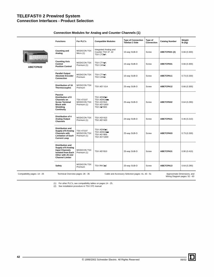
TELEFAST® 2 Prewired SystemConnection Interfaces - Product Selection
42
Compatibility pages: 14 - 25
ABE7CPA02
(1) For other PLC’s, see compatibility tables on pages 14 - 25.(2) See installation procedure in TSX 37E manual
Connection Modules for Analog and Counter Channels (1)
Functions For PLC’s Compatible Modules Type of Connection Telefast 2 Side
Type of Connection Catalog Number Weight
lb (kg)
Counting and Analog
MODICON TSX Micro (1)
Integrated Analog and Counter TSX 37 .22TSX CTZ�A
15-way SUB-D Screw ABE7CPA01 (2) 0.66 (0.300)
Counting Axis ControlPosition Control
MODICON TSX Premium (1)
TSX CTY�ATSX CAY�1
15-way SUB-D Screw ABE7CPA01 0.66 (0.300)
Parallel Output Absolute Encoder Connection
MODICON TSX Premium
TSX CTY�ATSX CAY�1
15-way SUB-D Screw ABE7CPA11 0.73 (0.330)
Distribution of 16 Thermocouples
MODICON TSX Premium
TSX AEY 614 25-way SUB-D Screw ABE7CPA12 0.66 (0.300)
Passive Distribution of 8 Channels on Screw Terminal Block with Shielding Continuity
TSX 47/107 MODICON TSX Premium (1)
TSX AEM8�1TSX AEM16��TSX ASY810TSX AEY1600TSX A�Y800
25-way SUB-D Screw ABE7CPA02 0.64 (0.290)
Distribution of 4 Analog Output Channels
MODICON TSX Premium (1)
TSX ASY410TSX AEY420
24-way SUB-D Screw ABE7CPA21 0.46 (0.210)
Distribution and Supply of 8 Analog Channels with Limitation of Each Current Loop
TSX 47/107MODICON TSX Premium (1)
TSX AEM8�1TSX AEM16��TSX AEY800TSX AEY1600
25-way SUB-D Screw ABE7CPA03 0.73 (0.330)
Distribution and Supply of 8 Analog Input Channels Isolated from Each Other with 25 mA/ Channel Limiter
MODICON TSX Premium (1)
TSX AEY810 25-way SUB-D Screw ABE7CPA31 0.90 (0.410)
SafetyMODICON TSX Premium
TSX PAY2�2 25-way SUB-D Screw ABE7CPA13 0.64 (0.290)
Technical Overview pages: 26 - 35 Cable and Accessory Selection pages: 41, 43 - 51 Approximate Dimensions, andWiring Diagram pages: 52 - 63
© 1999/2002 Schneider Electric All Rights Reserved 06/02

TELEFAST® 2 Prewired SystemConnection Interfaces - Product Selection
06/02
Compatibility pages: 14 - 25
ABE7ACC02
ABE7ACC80 + ABE7ACC81
ABE7BV20
2
2
0 1
0123456
7
8910
11
12
13
14
15
0 1
ABE7TES160
AR1SB3
ABFC08R���
Accessories for Modules
Software
Description Operating System Catalog Number Weight lb (kg)
Software for Customer Label Marking Under Windows Version 3.1 or 95 ABE7LOGV10 0.77 (0.350)
Pack of 25 Pre-cut Label Sheets (160 labels) – ABE7LOGF25 0.44 (0.200)
Accessories
Description No. of Channels Characteristics Order in
Multiples of: Catalog Number Weightlb (kg)
Kit for Mounting Modules Directly to a Panel
– – 10 ABE7ACC01 0.02 (0.008)
Splitter Block – 16 as 2 x 8 Channels 1 ABE7ACC02 0.17 (0.075)
Redundant Output Block – 16 as 2 x 16 Channels 1 ABE7ACC10 0.17 (0.075)
Redundant Input Block – 16 as 2 x 16 Channels 1 ABE7ACC11 0.17 (0.075)
Removable Continuity Blocks – 10 mm Wide 4 ABE7ACC20 0.02 (0.007)
– 12 mm Wide 4 ABE7ACC21 0.02 (0.010)
Locating Device for Removable Terminal Block – – 100 ABE7ACC30 0.02 (0.100)
Enclosure Feedthrough With Industrial Connector 32 40-way 1 ABE7ACC80 0.66 (0.300)
Plug-in 40-way Male Connector 32For Mounting on ABE7ACC80
1 ABE7ACC81 0.82 (0.370)
Enclosure Feedthrough with CNOMO M23 Connector(1 x 20-way HE 10 connector, PLC end)
16 19-way 1 ABE7ACC82 0.33 (0.150)
8 and 12 19-way 1 ABE7ACC83 0.33 (0.150)
Impedance Adaptor for Type 2 Compatibility
–Used with ABE7ACC82 and ABE7ACC83
1 ABE7ACC85 0.03 (0.012)
IP 65 Cable Gland – For 3 Cables 1 ABE7ACC84 0.66 (0.300)
Additional Snap-on Terminal Blocks(shunted terminals)
8 10 Screw Terminals 5 ABE7BV10 0.07 (0.030)
16 20 Screw Terminals 5 ABE7BV20 0.13 (0.060)
I/O Simulator 16Display, Forcing Inhibition, Continuity
1 ABE7TES160 0.77 (0.350)
Adhesive Label Holder – For 6 Characters 50 AR1SB3 0.002 (0.001)
Fast Blow Fuses 5 x 20 mm, 250 V, UL
– 0.125 A 10 ABE7FU012 0.02 (0.010)
0.5 A 10 ABE7FU050 0.02 (0.010)
1 A 10 ABE7FU100 0.02 (0.010)
2 A 10 ABE7FU200 0.02 (0.010)
4 A 10 ABE7FU400 0.02 (0.010)
6.3 A 10 ABE7FU630 0.02 (0.010)
“Flexible Jumpers” Accessories
Description For: Color Distance Between Cable Ends cm Catalog Number Weight
lb (kg)
Flexible Jumpers Modularity 8 x 1 mm2 Coil White 12 ABFC08R12W 0.04 (0.020)
2 ABFC08R02W 0.02 (0.010)
Vac Red 12 ABFC08R12R 0.04 (0.020)
2 ABFC08R02R 0.02 (0.010)
Vdc Blue 12 ABFC08R12B 0.04 (0.020)
2 ABFC08R02B 0.02 (0.010)
Technical Overview pages: 26 - 35 Module Selection pages: 36 - 40, 42 Approximate Dimensions, andWiring Diagram pages: 52 - 63
43© 1999/2002 Schneider Electric All Rights Reserved

TELEFAST® 2 Prewired SystemConnection Interfaces - Product Selection
44
Compatibility pages: 14 - 25
ABFH20H200
TSXCDP��3
TSXCCPS15
ABC6HE20F
(1) High density.(2) See color coded marking on page 62.
Connection Cables for MODICON TSX Micro and Premium PLC’s
Functions Compatible TSX Modules Type of Connection Gage
AWG
Cross-section mm2
Length Ft. (Meters) Catalog Number Weight
lb (kg)
PLC End Telefast 2 End
Discrete I/O DMZ�DTKDEZ��D2KDSZ��T2KDEY��D2KDSY��T2KDEY��16FK
20-way HE 10 20-way HE 10 28 0.080 3.28 (1) ABFH20H100 0.18 (0.080)
6.56 (2) ABFH20H200 0.31 (0.140)
9.84 (3) ABFH20H300 0.46 (0.210)
22 0.324 1.64 (0.5) TSXCDP053 0.19 (0.085)
3.28 (1) TSXCDP103 0.33 (0.150)
6.56 (2) TSXCDP203 0.62 (0.280)
9.84 (3) TSXCDP303 0.90 (0.410)
16.41 (5) TSXCDP503 1.48 (0.670)
Universal Bare Wires 20-way HE 10 22 0.324 9.84 (3) TSXCDP301 0.88 (0.400)
16.41 (5) TSXCDP501 1.46 (0.660)
Analog AEY�� 25-way SUB-D 25-way SUB-D 24 0.205 9.84 (3) TSXCAP030 1.48 (0.670)
Universal Bare Wires 25-way SUB-D 24 0.205 6.56 (2) ABFF25S200 (2) 0.66 (0.300)
ASY410 TSXBLY01 25-way SUB-D 24 0.205 6.56 (2) ABFY25S200 0.83 (0.375)
Analog and Counter / Counter
3722��CTY�A
15-way SUB-D 15-way SUB-D 24 0.205 8.20 (2.5) TSXCCPS15 0.49 (0.220)
Counter CTZ�A15-way SUB-D (1)
15-way SUB-D 24 0.205 8.20 (2.5) TSXCCPH15 0.49 (0.220)
Axis Control CAY�1 9-way SUB-D 9-WAY SUB-D 24 0.205 6.56 (2) TSXCXP213 0.60 (0.270)
19.69 (6) TSXCXP613 1.28 (0.580)
Accessories
Description Gauge AWG Cross-section mm2
Length ft. (m) Sold in Lots of: Catalog Number Weight
lb (kg)
Rolled Ribbon Cable 28 0.0865.6 ft (20)
1 ABFC20R200 2.89 (1.310)
20-way HE 10 Connector – – – 2 ABC6HE20F 0.02 (0.008)
Technical Overview pages: 26 - 35 Module Selection pages: 36 - 40, 42
© 1999/2002 Schneider Electric All Rights Reserved 06/02

TELEFAST® 2 Prewired SystemConnection Interfaces - Product Selection
06/02
Compatibility pages: 14 - 25
TSXBLK�1
ABFB50S�01
ABFH20H��1
Terminal Blocks, Cabled Connectors and Connection Cables for TSX 47 to 107 PLC’s
Connection Terminal Blocks (with LED display of I/O)
Number of Channels Type of Discrete Interface Type of Connection Catalog Number Weight
lb (kg)
32 TSXDET32�2 Inputs 2 x 20-way Male HE 10 Connectors TSXBLK71 0.04 (0.200)
TSXDST32�2 Outputs 2 x 20-way Male HE 10 Connectors TSXBLK91 0.04 (0.200)
24 TSXDST24�2 Outputs 1 x 34-way Male HE 10 Connectors TSXBLK81 (1) 0.04 (0.200)
Cabled Connectors for TSXAEM�� and TSXDST16�� Modules
Type of Signal Type of Connection Gauge AWG Cross-section mm2
Length ft. (m) Modularity Catalog Number Weight
lb (kg)
PLC End Telefast End
Analog
Terminal Block BLK 4 Included
2 x 25-way SUB-D
24 0.22
6.56 (2) 16 ABFB50S201 1.12 (0.510)
9.84 (3) 16 ABFB50S301 1.68 (0.760)
1 X 25-way SUB-D
24 0.226.56 (2) 8 ABFB25S201 1.10 (0.500)
9.84 (3) 8 ABFB25S301 1.48 (0.670)
Connector Cables
Type of Signal Type of Connection Gauge AWG Cross-section mm2
Lengthft. (m) Modularity Catalog Number Weight
lb (kg)
PLC End Telefast End
Discrete I/O1 x 34-way HE 10 on BLK 81
1 x 34-way HE 10
28 0.08
3.28 (1) 24 ABFH34H100 (1) 0.12 (0.055)
6.56 (2) 24 ABFH34H200 (1) 0.22 (0.100)
9.84 (3) 24 ABFH34H300 (1) 0.32 (0.145)
1 x 20-way HE 10 with Power on BLK 71/91
1 X 20-wayHE 10
28 0.08
4.92 (1.5) 16 ABFH20H151 0.24 (0.110)
6.56 (2) 16 ABFH20H201 0.31 (0.140)
9.84 (3) 16 ABFH20H301 0.46 (0.210)
16.4 (5) 16 ABFH20H501 0.77 (0.350)
Analog
1 x 25-way SUB-D on TSX AEM 1613
1 X 25-way SUB-D
24 0.22 9.84 (3) 16 ABFS25S301 1.37 (0.620)
Splitter Block for TSXDST24�2
Splitter Block, 24 Channels, 3 x 8 Channels ABE7ACC03 0.25 (0.115)
Correspondence Tables
ABFS25S30� ABFB25S�01 ABFB50S�01
Male SUB-D Pins
No. of Cable Pairs
Female SUB-D Pins
25-way SUB-D TSXBLK4 25-way SUB-D25-way SUB-D (1)
TSXBLK425-way SUB-D (2)
1-2 1 1-2 Term. No. Channels Term. Blk. Channels Term. No. Term No. Term. Blk. Term. No.
3-14 2 3-14 A C A C
15-16 3 15-16 1-2 V0+ 8 1 V4+ 7-8 1-2 8 1 1-2
4-5 4 4-5 14 V0- 7 2 V4- 20 14 7 2 14
6-17 5 6-17 Ground 6 3 Ground 15-16 6 3 15-16
18-19 6 18-19 15-16 V1+ 5 4 V5+ 21-22 3 5 4 3
7-8 7 7-8 3 V1- 4 5 V5- 9 4-5 4 5 4-5
9-20 8 9-20 Ground 3 6 Ground 17 3 6 17
21-22 9 21-22 4-5 V2+ 2 7 V6+ 10-11 18-19 2 7 18-19
10-11 10 10-11 17 V2- 1 8 V6- 23 6 1 8 6
12-23 11 12-23 B D B D
24-25 12 24-25 Ground 8 1 Ground 7-8 8 1 7-8
13 13 13 18-19 V3+ 7 2 V7+ 24-25 20 7 2 20
6 V3- 6 3 V7- 12-13 21-22 6 3 21-22
Ground 5 4 Ground 9 5 4 9
4 5 10-11 4 5 10-11
3 6 23 3 6 23
2 7 24-25 2 7 24-25
1 8 12-13 1 8 12-13
(1) Splitter block ABE7ACC03 must be used.
Technical Overview pages: 26 - 35 Module Selection pages: 36 - 40, 42
45© 1999/2002 Schneider Electric All Rights Reserved

TELEFAST® 2 Prewired SystemConnection Interfaces - Product Selection
46
Compatibility pages: 14 - 25
ABE7ACC04
Cables and Splitter Blocks for NUM Numerical Control
Description For NUMProcessor Unit
Type of Signal Type of Connection Catalog Number Weightlb (kg)
Processor Unit End Telefast End
Splitter Blocks102010501060
32 Channel (input) 37-way Male SUB-D 2 x 20-way HE 10 ABE7ACC04 0.22 (0.100)
24 Channels (output)
37-way Female SUB-D
3 x 20-way HE 10 ABE7ACC05 0.23 (0.105)
Example of Connection
ABE7ACC04 ABE7ACC05
20-way HE 10 B SUB-D A 20-way HE 10 C 25-way HE 10 B SUB-D A 20-way HE 10 C
Term. No. Channels Term. Blk. Channels Term. No. Term. No. Channels Term. Blk. Channels Term. No.
1 0 1 29 16 1 1 0 4 13 8 1
2 1 20 11 17 2 2 1 25 31 9 2
3 2 2 30 18 3 3 2 24 12 10 3
4 3 21 12 19 4 4 3 20 30 11 4
5 4 3 31 20 5 5 4 21 28 12 5
6 5 22 13 21 6 6 5 22 8 13 6
7 6 4 32 22 7 7 6 23 5 14 7
8 7 23 14 23 8 8 7 1 7 15 8
9 8 24 15 24 9 13 to 17-19 24 Vdc 2-10-15-19 24 Vdc 13 to 17-19
10 9 6 34 25 10 18 to 20 0 Vdc 3-9-14-34 0 Vdc 18-20
11 10 25 16 26 11 9 to 12 NC NC 9 to 12
12 11 7 35 27 12 20-way
13 12 26 17 28 13 HE 10 D
14 13 8 36 29 14 Terminal no. Channels Terminal blk.
15 14 27 18 30 15 1 16 37
16 15 9 37 31 16 2 17 18
17 24 Vdc 10 10 24 Vdc 17 3 18 36
18 0 Vdc 5 28 0 Vdc 18 4 19 17
19 NC NC 19 5 20 35
20 0 Vdc 19 33 0 Vdc 20 6 21 16
7 22 33
8 23 32
13 to 17-19 24 Vdc 2-10-15-19
18 to 20 0 Vdc 3-9-14-34
9 to 12 NC
Technical Overview pages: 26 - 35 Module Selection pages: 36 - 40, 42 Approximate Dimensions, andWiring Diagram pages: 52 - 63
AB C D
AB C
2
55
43
21
1 NUM numerical controller2 NUM cables3 ABE7ACC04 splitter block4 ABE7ACC05 splitter block5 Telefast modules
© 1999/2002 Schneider Electric All Rights Reserved 06/02

TELEFAST® 2 Prewired SystemConnection Interfaces - Product Selection
06/02
Compatibility pages: 14 - 25
ABFA32H�00
Cabled Connectors and Connection Cables for APRIL Series 1000 PLC’s
Cabled Connectors for APRIL Series 1000 PLC’s
Type of Signal Type of Connection Gauge AWG
Cross-section mm2
Lengthft. (m) Modularity Catalog Number Weight
lb (kg)
PLC End Telefast End
Inputs and Relay Outputs
PIN 0100 Term. Block Included
2 x 20-way HE 10
26 0.136.56 (2) 2 x 16 ABFA32H200 0.99 (0.450)
9.84 (3) 2 X 16 ABFA32H300 1.37 (0.620)
0.5 A OutputPIN 0100 Term. Block with External Power Supply
2 x 20-way HE 10
22 0.324 4.92 (1.5) 2 x 16 ABFA32H151 1.43 (0.650)
9.84 (3) 2 X 16 ABFA32H301 2.54 (1.150)
Connection Cable for APRIL IXA/IRA 1600 Module
Type of Signal Type of Connection Gauge AWG
Cross-section mm2
Length Meter
Modularity Catalog Number Weight lb (kg)
PLC End Telefast End
Analog 1 x 25-way SUB-D1 x 25-way SUB-D
24 0.22 9.84 (3) 16 ABFS25S302 1.37 (0.620)
Examples of Connection
Correspondence Tables Between the PLC Terminal Block and HE 10 ConnectorsABFA32H��00 ABFA32H�01
20-way HE 10 (1) PIN0100 20-way HE 10 (2) 20-way HE 10 (1) PIN0100 20-way HE 10 (2)
Term. No. Name Term. Blk. Name Term. No. Term. No. Name Term. Blk. Name Term. No.
1 Q0 2 12 Q16 1 1 Q0 2 12 Q16 1
2 Q1 22 32 Q17 2 2 Q1 22 32 Q17 2
3 Q2 3 13 Q18 3 3 Q2 3 13 Q18 3
4 Q3 23 33 Q19 4 4 Q3 23 33 Q19 4
5 Q4 4 14 Q20 5 5 Q4 4 14 Q20 5
6 Q5 24 34 Q21 6 6 Q5 24 34 Q21 6
7 Q6 5 15 Q22 7 7 Q6 5 15 Q22 7
8 Q7 25 35 Q23 8 8 Q7 25 35 Q23 8
9 Q8 7 17 Q24 9 9 Q8 7 17 Q24 9
10 Q9 27 37 Q25 10 10 Q9 27 37 Q25 10
11 Q10 8 18 Q26 11 11 Q10 8 18 Q26 11
12 Q11 28 38 Q27 12 12 Q11 28 38 Q27 12
13 Q12 9 19 Q28 13 13 Q12 9 19 Q28 13
14 Q13 29 39 Q29 14 14 Q13 29 39 Q29 14
15 Q14 10 20 Q30 15 15 Q14 10 20 Q30 15
16 Q15 30 40 Q31 16 16 Q15 30 40 Q31 16
17 24 Vdc 1 11 24 Vdc 17 17 NC NC NC NC 17
18 0 Vdc 21 31 0 Vdc 18 18 0 Vdc 21/26 31/36 0 Vdc 18
19 24 Vdc 6 16 24 Vdc 19 19 NC NC NC NC 19
20 0 Vdc 26 36 0 Vdc 20 20 NC NC NC NC 20
Power supply cable
24 Vdc 1/6 11/16 24 VdcPower supply cable
Technical Overview pages: 26 - 35 Module Selection pages: 36 - 40, 42
0 1 2 3 4 5 6 7 8 9 10 11 12 13 14 150 1 2 3 4 5 6 7 8 9 10 11 12 13 14 15
2
1
24 Vdc
24 Vdc
1 ABFA32H��12 ABE7H16R21
47© 1999/2002 Schneider Electric All Rights Reserved

TELEFAST® 2 Prewired SystemConnection Interfaces - Product Selection
48
Compatibility pages: 14 - 25
ABFM16H��0
Cabled Connectors for MODICON 984-A120-COMPACT PLC’s
Type of Signal Type of Connection Gauge AWG
Cross-section mm2
Length ft. (m)
Modularity Catalog Number Weight lb (kg)
Input and Relay Output
1 x 20-way HE 10 22 0.3244.92 (1.5) 16 ABFM16H150 0.66 (0.300)
9.84 (3) 16 ABFM16H300 1.21 (0.550)
0.5 A Output 2 x 20-way HE 10 22 0.3244.92 (1.5) 2 x 8 ABFM16H151 1.10 (0.500)
9.84 (3) 2 x 8 ABFM16H301 2.20 (1.000)
Correspondence TablesABFM16H��0 ABFM16H��1
20-way HE 10984A120 COMPACT
20-way HE 10 (1)984A120 COMPACT
20-way HE 10 (2)
Term. No. Channel Term. Blk. Term. No. Channel Term. Blk. Channel Term. No.
1 1 3 1 1 3 14 9 1
2 2 4 2 2 4 15 10 2
3 3 5 3 3 5 16 11 3
4 4 6 4 4 6 17 12 4
5 5 7 5 5 7 18 13 5
6 6 8 6 6 8 19 14 6
7 7 9 7 7 9 20 15 7
8 8 10 8 8 10 21 16 8
9 9 14 9-10-11-12 NC NC 9-10-11-12
10 10 15 13-15-17 24 Vdc 1 12 24 Vdc 13-15-17
11 11 16 14-16-19 24 Vdc 2 13 24 Vdc 14-16-19
12 12 17 18-20 0 Vdc 11 22 0 Vdc 18-20
13 13 18
14 14 19
15 15 20
16 16 21
17 24 Vdc 1
18 0 Vdc 11
19 24 Vdc 12
20 0 Vdc 22
Technical Overview pages: 26 - 35 Module Selection pages: 36 - 40, 42
© 1999/2002 Schneider Electric All Rights Reserved 06/02

TELEFAST® 2 Prewired SystemConnection Interfaces - Product Selection
06/02
Correspondence TablesABFM32H��0
20-way QUANTUM
HE 10 (1)
Term. no. Channel Term. blk
1 1 1 21
2 2 2 22
3 3 3 23
4 4 4 24
5 5 5 25
6 6 6 26
7 7 7 27
8 8 8 28
9 9 11 31
10 10 12 32
11 11 13 33
12 12 14 34
13 13 15 35
14 14 16 36
15 15 17 37
16 16 18 38
17 24 Vdc 10 30
18 0 Vdc 9 29
19 24 Vdc 20 40
20 0 Vdc 19 39
ABFM08S201
Pair SUB D QUANTUM
Term. blk
1 1 1 3
2 3 6 2
3 15 5 7
4 4 11 13
5 17 12 16
6 18 15 17
7 7 21 23
8 20 22 26
9 21 25 27
10 10 31 33
11 23 32 36
12 24 35 37
Compatibility pages: 14 - 25
ABFM32H��1
Cabled Connectors for MODICON QUANTUM PLC’s
Type of Signal I/O Module Type of Connection Gauge AWG
Cross-section mm2
Lengthft. (m)
Modularity Catalog Number Weight lb (kg)
Input and Relay Output
–2 x 20-way HE 10
22 0.324 4.92 (1.5) 2 x 16 ABFM32H150 1.43 (0.650)
9.84 (3) 2 X 16 ABFM32H300 2.54 (1.150)
0.5 A Output –2 x HE 10 20-way + Ext. Supply
22 0.324 4.92 (1.5) 2 x 16 ABFM32H151 1.43 (0.650)
9.84 (3) 2 X 16 ABFM32H301 2.54 (1.150)
Analog Input140 AVI/ACI 03000
1 X 25-way SUB-D 24 0.22 6.56 (2) 8 ABFM08S201 1.32 (0.600)
140 ACI 04000
2 X 25-way SUB-D 24 0.22 6.56 (2) 16 ABFM16S201 1.37 (0.620)
Analog Output140 AVO 02000
1 x 25-way SUB-D 24 0.22 6.56 (2) 4 ABFM04S200 0.99 (0.450)
140 ACO 02000
1 x 25-way SUB-D 24 0.22 6.56 (2) 4 ABFM04S201 0.99 (0.450)
140 ACO 13000
1 x 25-way SUB-D 24 0.22 6.56 (2) 8 ABFM08S202 0.99 (0.450)
ABFM32H��1 ABFM08S202
20-way 20-way QUANTUM 20-way Pair SUB D MODICON SUB D Pair
HE 10 (2) HE 10 (1) HE 10 (2) Term. blk
Channel Term. no. Term. no. Channel Term. blk Channel Term. no. 1 2 4 1
17 1 1 1 1 21 17 1 2 16 8 2
18 2 2 2 2 22 18 2 3 5 14 3
19 3 3 3 3 23 19 3 4 19 18 4
20 4 4 4 4 24 20 4 5 8 24 5
21 5 5 5 5 25 21 5 6 22 28 6
22 6 6 6 6 26 22 6 7 11 34 36 13 7
23 7 7 7 7 27 23 7 8 25 38 8
24 8 8 8 8 28 24 8
25 9 9 9 11 31 25 9 ABFM16S201
26 10 10 10 12 32 26 10 Pair SUB D MODICON SUB D Pair
27 11 11 11 13 33 27 11 Term. blk
28 12 12 12 14 34 28 12 1 14 2 1 2 1
29 13 13 13 15 35 29 13 2 3 4 3 16 2
30 14 14 14 16 36 30 14 3 17 6 5 5 3
31 15 15 15 17 37 31 15 4 6 8 7 19 4
32 16 16 16 18 38 32 16 5 20 12 11 8 5
24 Vdc 17 17 NC NC 17 6 9 14 13 22 6
0 Vdc 18 18 0 Vdc 9/19 29/39 0 Vdc 18 7 23 16 15 11 7
24 Vdc 19 shunt shunt 8 12 18 17 25 8
0 Vdc 20 19 NC NC 19 1 14 22 21 2 1
20 NC NC 20 2 3 24 23 16 2
Pwr. supply 24 Vdc 10/20 30/40 24 Vdc Pwr. supply 3 17 26 25 5 3
Cable Shunt Shunt Cable 4 6 28 27 19 4
5 20 32 31 8 5
6 9 34 33 22 6
7 23 36 35 11 7
8 12 38 37 25 8
ABFM04S200 ABFM04S201
SUB D Pair Pair SUB D QUANTUM SUB D Pair Pair SUB D QUANTUM SUB D Pair
Term. blk Term. blk
2 1 1 14 2 1 1 1 5 14 2 1 2 5
14 2 5 2 8 5 1 14 10 9 1 1
16 3 2 3 12 11 15 2 6 3 12 11 16 6
5 4 6 16 18 6 2 3 20 19 15 2
6 5 3 17 22 21 4 3 7 17 22 21 5 7
19 6 7 5 28 7 3 17 30 29 4 3
8 7 4 6 32 31 18 4 8 6 32 31 19 8
9 8 8 19 38 8 4 6 40 39 18 4
22 9
11 10
12-13 11
25 12
Technical Overview pages: 26 - 35 Module Selection pages: 36 - 40, 42
49© 1999/2002 Schneider Electric All Rights Reserved

TELEFAST® 2 Prewired SystemConnection Interfaces - Product Selection
50
Compatibility pages: 14 - 25
ABFH40H��0
Connection Cables for ALLEN BRADLEY PLC’s
Connection Cables for ALLEN BRADLEY SLC 500 PLC’s
Type of Signal Type of Connection Gauge AWG
Cross-section mm2
Lengthft. (m) Modularity Catalog Number Weight
lb (kg)
PLC End Telefast End
32 Channel Input 40-way HE 102 x 20-way HE 10
22 0.3244.92 (1.5) 16 ABFH40H150 0.77 (0.350)
9.48 (3) 16 ABFH40H300 1.76 (0.800)
100 mA 32 Channel Output
40-way HE 102 x 20-way HE 10
22 0.3244.92 (1.5) 16 ABFH40H151 0.77 (0.350)
9.48 (3) 16 ABFH40H301 1.76 (0.800)
16 Channel Input Terminal Block1 x 20-way HE 10
22 0.324 6.56 (2) 16 ABFR16H201 1.76 (0.800)
16 Channel Output Terminal Block1 x 20-way HE 10
22 0.324 6.56 (2) 16 ABFR16H200 1.76 (0.800)
Correspondence TablesABFH40H��0 ABFH40H��1
20-way HE 10 (1)SLC500
1 X 40-way20-way HE 10 (2) 20-way HE 10 (1)
SLC5001 X 40-way
20-way HE 10 (2)
Term. No. Channels HE 10 Channels Term. No. Term. No. Channels HE 10 Channels Term. No.
1 0 5 6 16 1 1 0 5 6 16 1
2 1 7 8 17 2 2 1 7 8 17 2
3 2 9 10 18 3 3 2 9 10 18 3
4 3 11 12 19 4 4 3 11 12 19 4
5 4 13 14 20 5 5 4 13 14 20 5
6 5 15 16 21 6 6 5 15 16 21 6
7 6 17 18 22 7 7 6 17 18 22 7
8 7 19 20 23 8 8 7 19 20 23 8
9 8 21 22 24 9 9 8 21 22 24 9
10 9 23 24 25 10 10 9 23 24 25 10
11 10 25 26 26 11 11 10 25 26 26 11
12 11 27 28 27 12 12 11 27 28 27 12
13 12 29 30 28 13 13 12 29 30 28 13
14 13 31 32 29 14 14 13 31 32 29 14
15 14 33 34 30 15 15 14 33 34 30 15
16 15 35 36 31 16 16 15 35 36 31 16
17 NC NC 17 17 24 Vdc 1 2 24 Vdc 17
18 0 Vdc 1 2 0 Vdc 18 18 0 Vdc 37 38 0 Vdc 18
19 NC NC 19 19 24 Vdc 3 4 24 Vdc 19
20 0 Vdc 39 40 0 Vdc 20 20 0 Vdc 39 40 0 Vdc 20
ABFR16H200 ABFR16H201
20-way SLC 500 20-way 20-way SLC 500 20-way
HE 10 Terminal block HE 10 HE 10 Terminal block HE 10
17-19 Vdc OUT 0 1 – – IN 0 1
2 OUT 1 OUT 2 3 2 IN 1 IN 2 3
4 OUT 3 OUT 4 5 4 IN 3 IN 4 5
6 OUT 5 OUT 6 7 6 IN 5 IN 6 7
8 OUT 7 OUT 8 9 8 IN 7 IN 8 9
10 OUT 9 OUT 10 11 10 IN 9 IN 10 11
12 OUT 11 OUT 12 13 12 IN 11 IN 12 13
14 OUT 13 OUT 14 15 14 IN 13 IN 14 15
16 OUT 15 0 V 18-20 16 IN 15 0 V 18-20
Technical Overview pages: 26 - 35 Module Selection pages: 36 - 40, 42
© 1999/2002 Schneider Electric All Rights Reserved 06/02

TELEFAST® 2 Prewired SystemConnection Interfaces - Product Selection
06/02
Correspondence Tables
ABFH1
20-way
Term. n
1
2
3
4
5
6
7
8
9
10
11
12
13
14
15
16
17
18
19
20
ABFS16H200
20-way HE 10 SIEMENS S5
Term. no. Channel Extension plat
13-14-15- 24 Vdc 1 1
17-19
18-20 0 Vdc 2 2
2 E 1 3 3
1 E 0 4 4
4 E 3 5 5
3 E 2 6 6
6 E 5 7 7
5 E 4 8 8
8 E 7 9 9
7 E 6 10 10
Compatibility pages: 14 - 25
ABFH32H��0
Connection Cables for SIEMENS PLC’s
Type of SignalType of Connection Gauge
AWGCross-section mm2
Lengthft. (m) Modularity Catalog Number
Weight lb (kg)PLC End Telefast End
24 v Input and Relay Output
2 x 14--way HE 101 x 20-way HE 10
26 0.134.92 (1.5) 16 ABFH28H150 0.33 (0.150)
9.84 (3) 16 ABFH28H300 0.55 (0.250)
8 Channel I/O Extension Plate2 X 20-way HE 10
22 0.32 6.56 (2) 2 X 8 ABFS16H200 1.32 (0.600)
0.5 A Output 1 x 14-way he 101 X 20-way HE 10
26 0.134.92 (1.5) 8 ABFH14H150 0.33 (0.150)
9.84 (3) 8 ABFH14H300 0.77 (0.350)
Connection Cables for SIEMENS S7 PLC’s
24 V Input and Relay Output
2 x 16-way HE 101 x 20-way HE 10
26 0.134.92 (1.5) 16 ABFH32H150 0.35 (0.160)
9.84 (3) 16 ABFH32H300 0.57 (0.260)
8 Channel Input Terminal Block1 x 20-way HE 10
22 0.32 6.56 (2) 8 ABFS08H202 0.77 (0.350)
0.5 A Output 1 x HE 10 1 X HE 10 26 0.134.92 (1.5) 8 ABFH16H150 0.35 (0.160)
9.84 (3) 8 ABFH16H300 0.57 (0.260)
8 Channel Output Terminal Block1 x 20-way HE 10
22 0.32 6.56 (2) 8 ABFS08H203 0.77 (0.350)
Analog Bare Wires25-way SUB-D
24 0.205 6.56 (2) – ABFF25S200 1.32 (0.600)
14 Channel Input10 Channel Output
Terminal Block2 x 20-way HE 10
22 0.32 6.56 (2) 24 ABFS24H200 2.03 (0.920)
4H��0 ABFH28H��0 ABFH16H��0 ABFH32H��0
HE 10 SIEMENS S5 20-way HE 10 SIEMENS S5 20-way HE 10 SIEMENS S7 20-way HE 10 SIEMENS S7
o. Channel 14-way HE 10 Term. no. Channel 2 x 14-way HE 10 Term. no. Channel 16-way HE 10 Term. no. Channel 2 x 16-way HE 10
0 1 1 0 1 1 0 16 1 0 16
1 2 2 1 2 2 1 14 2 1 14
2 3 3 2 3 3 2 12 3 2 12
3 4 4 3 4 4 3 10 4 3 10
4 5 5 4 5 5 4 8 5 4 8
5 6 6 5 6 6 5 6 6 5 6
6 7 7 6 7 7 6 4 7 6 4
7 8 8 7 8 8 7 2 8 7 2
NC 9 8 1 9 NC 9 8 16
NC 10 9 2 10 NC 10 9 14
NC 11 10 3 11 NC 11 10 12
NC 12 11 4 12 NC 12 11 10
NC 13 12 5 13 NC 13 12 8
NC 14 13 6 14 NC 14 13 6
NC 15 14 7 15 24 Vdc 9 15 14 4
24 Vdc 9 16 15 8 16 24 Vdc 11 16 15 2
24 Vdc 11 17 24 Vdc 13 17 24 Vdc 13 17 24 Vdc 13
0 Vdc 12 18 0 Vdc 14 18 0 Vdc 1 18 0 Vdc 1
+ 24 Vdc 13 19 24 Vdc 13 19 24 Vdc 15 19 24 Vdc 13
0 Vdc 14 20 0 Vdc 14 20 0 Vdc 3 20 0 Vdc 1
ABFS24H200 ABFS08H203 ABFS08H202
20-way HE 10 SIEMENS S7 20-way HE 10 20-way HE 10 SIEMENS S7 20-way HE 10 SIEMENS S7
e Channel Term. no. Channel Terminal block Channel Term. no. Term. no. Channel Term. block Term. no. Channel Term. block
24 Vdc 18 0 V 1 M 1 M 0 V 18 18 0 Vdc 1 M 13-14-15 24Vdc 1 M
1 0 0.0 1 L+ + 24 V 13-14-15 13-14-15 24 Vdc 1 L+ 1 E1 0.0
0 Vdc 2 1 0.1 0.0 0 1 1 E1 0.0 2 E2 0.1
E 1 3 2 0.2 0.1 1 2 2 E2 0.1 3 E3 0.2
E 0 4 3 0.3 0.2 2 3 3 E3 0.2 4 E4 0.3
E 3 5 4 0.4 0.3 3 4 4 E4 0.3 16-17-19 24Vdc 2 M
E 2 6 5 0.5 0.4 4 5 20 0 Vdc 2 M 5 E5 0.4
E 5 7 6 0.6 2 M 0 V 20 16-17-19 24 Vdc 2 L+ 6 E6 0.5
E 4 8 7 0.7 2 L+ + 24 V 16-17-19 1 E1 0.4 7 E7 0.6
E 7 20 0 V 2 M 0.5 5 6 2 E2 0.5 8 E8 0.7
E 6 9 8 1.0 0.6 6 7 3 E3 0.6
10 9 1.1 0.7 7 8 4 E4 0.7
11 10 1.2 1.0 8 9
12 11 1.3 1.1 9 10
13 12 1.4 – – –
14 13 1.5 – – –
Technical Overview pages: 26 - 35 Module Selection pages: 36 - 40, 42
51© 1999/2002 Schneider Electric All Rights Reserved

TELEFAST® 2 Prewired SystemConnection Interfaces - Approximate Dimensions
52
ABE 7H20E/7
b 2.64 (67)
b1 2.20 (56)
c 2.32 (59)
1 Additional shunt terminal block AB
Comm
ABE 7������
b 2.76 (70)
b1 2.28 (58)
c 2.28 (58)
1 Additional shunt terminal block AB
ABE7R16T2��, ABE7P16T2��
Common side viewABE7R16T3��, ABE7P16T3��, AB
1
2.5264 2.87
73
1.38 35
0.5915
2.28 58
2.9174 3.27
83
1.38 35
0.5915
2.28 58
Approximate Dimensions
Common side view ABE7H20E��� ABE7H16R50, ABE7H12R50, ABE7H16C��/ABE7H16CM��, ABE7H32E��� ABE7H08R1�, ABE7H08R21, ABE7�16M111/ABE7�16T111
ABE7R08S111/S111E,ABE7H08S21, ABE7CPA21
H32E��� 7H�����/CPA21 7R08S111� ABE 7H16C��/CM�� 7�16M111/T111
2.76 (70) 3.03 (77) a 4.17 (106) 4.33 (110)
2.28 (58) 2.28 (58) b 1.93 (49) 3 50 (89)
2.28 (58) 2.28 (58) b1 1.63 (41.5) 2.28 (58)
c 2.36 (60) 2.13 (54)
E7BV10/7BV20
on side view ABE7H16R2�, ABE7H12R2�, ABE7H16R3�, ABE7R16S21�, ABE7H16�43ABE7H16R1�, ABE7H12R1�, ABE7H12S21, ABE7S16S2B0/S2B02E, ABE7H16S2�, ABE7R16S11�, ABE7R08S210, ABE7S16E2��/S16E2��EABE7S08S2B0, ABE7CPA02, ABE7CPA03 ABE7S08S2B1/S08S2B1EABE7S16S1B2, ABE7R08S216 ABE7CPA31
7�R08S210�, 7S16S1B2�, 7R08S216 All modules
3.03 (77) b1 2.28 (58)
2.28 (58) c 2.28 (58)
2.28 (58)
E7BV10/7BV20
ABECPA01, ABE7CPA11/CPA12/CPA13
E7P16F31� ABE7P08T330
2.1755
bb
c
c + 91.
38 35b1
0.5915
3.3184
1a
1
11
3.03 77
8.11206
2.76 70
b +
12
b
4.92125c
c1
1.38 35
b1
0.5915
3.50 89
8.31211
2.76 70
2.2858 2.64
67
1.38 35
5.63143
Note:Details of the front view are the same as for the ABE7CPA01
10.71272
3.50 89 3.
50 89
5.91150
Dual Dimensions inchesmm
© 1999/2002 Schneider Electric All Rights Reserved 06/02

TELEFAST® 2 Prewired SystemConnection Interfaces - Approximate Dimensions
06/02
ABE7ACC02
ABE7ACC80
ABE7ACC84
Mounting centers for modules us
1.8948 2.24
57
1.9650
1.38
35
0.5915
A B
2.28 58
26
1.6943
2.1354
1.65422.91
74
1.691 6943
2.8372 2.13
54
g=a0.47G = a-12
a
0.14Ø3.5
ABE7ACC03 ABE7ACC04, ABE7ACC05ABE7ACC10, ABE7ACC11
ABE7ACC82, ABE7ACC83
ABE7TES160
ing mounting kit ABE7ACC01
In (mm) In (mm) In (mm) In (mm) In (mm) In (mm)
ABE7 G H ABE7 G H ABE7 G H
ACC02 1.50 (38) 3.23 (82) H12R1� 4.49 (113) 3.23 (82) H16F43 7.64 (194) 3.23 (82)
ACC03 2.09 (53) 3.98 (101) H12R2� 4.49 (113) 3.23 (82) H16S43 7.64 (194) 3.23 (82)
ACC04 2.09 (53) 3.98 (101) H16R1� 4.49 (113) 3.23 (82) S16E2�� 7.64 (194) 3.23 (82)
ACC05 2.09 (53) 3.98 (101) H16R2� 4.49 (113) 3.23 (82) S16S1B2 4.49 (113) 3.23 (82)
ACC10/11 2.09 (53) 3.98 (101) H16R3� 4.49 (113) 3.23 (82) S16S2�� 7.64 (194) 3.23 (82)
H08R�� 2.85 (72) 3.23 (82) H12S21 4.49 (113) 3.23 (82) R16T2�� 7.83 (199) 3.98 (101)
H08S21 2.85 (72) 3.23 (82) H16S21 4.49 (113) 3.23 (82) P16T2�� 7.83 (199) 3.98 (101)
H12R50 2.85 (72) 3.23 (82) R08S210 4.49 (113) 3.23 (82) R16T3�� 10.24 (260) 3.98 (101)
H16R50 2.85 (72) 3.23 (82) R16S111 4.49 (113) 3.23 (82) P08T330 5.91 (150) 3.98 (101)
R08S111 2.85 (72) 3.23 (82) R16S21� 7.64 (194) 3.23 (82) P16T3�� 10.24 (260) 3.98 (101)
CPA01 5.16 (131) 3.23 (82) S08S2B0 4.49 (113) 3.23 (82) P16F3�� 10.24 (260) 3.98 (101)
CPA02 4.49 (113) 3.23 (82) S08S2B1 7.64 (194) 3.23 (82)
CPA1� 5.16 (131) 3.23 (82)
CPA03 4.49 (113) 3.23 (82)
2.76
70
C
3.4688
3.50 89
BA C D
1.8948 2.24
57
1.38 35
0.5915
2.28 58
2.6066
3.50 89
BA
C D
1.8948 2.24
57
1.38 35
0.5915
2.28 58
Note: Drawing representing ABE7ACC04 and ABE7ACC05
.544.5
5.51
140
4.40
112
5.12
130
1.2632
1.3835
0.174xØ4.3
0.9825
1.3434
3.46 88
2.5665
2.0552
1.97 50
0.162xØM41.
04Ø
26.5 0.20 (2XØ5)
1.10 (( 28)3.
15 804.
0610
3
1.2632
1.1830
120
0.174XØ4.3 2.32
59
1.9750
1.38 35
0.5915
6.69170
3.50 89
2.28 58
0.246
H=
b+0.
47H
= b
+12
b
Dual Dimensions inchesmm
53© 1999/2002 Schneider Electric All Rights Reserved

TELEFAST® 2 Prewired SystemConnection Interfaces - Wiring Diagrams
54
Connection of terminal block com
Pos
ABE7H08S21
ABE7H08R�� (R10 with no LED)
21 3 4
ON
0 V
0 V
1
X124 V
24 V
2003 10
0
41 2
220
1 101
8 C
2003 10
0
41 2
201 10
1
0 V
0 V
1
X124 V
24 V
2
100
1 2 3 4 101
8
8
Wiring Diagrams
NOTE: Disconnect all power before making connection, if voltage is greater than 42.4 V or 30 Vac.
mon (on ABE7H��S21 and ABE7H16R3� modules only)
ition 1 Position 2
Connection is made using a shunt.
The shunt is supplied with the module and is mounted in the neutral position between terminals 2-3.
It may be connected:
– either to + for positive logic inputs across terminals 1-2 (position 1),– or to – for positive logic outputs across terminals 3-4 (position 2).
For modules ABE7H16R3�, the shunt is in -position 1. A second wire shunt must be connected between the 3rd row common (C) and first row terminal 4 (OV).
ABE7H12S21
ABE7H12R�� (R20, R10 and R50 with no LED)
21 3 4
ON
19
208 17
13
18
107
207
hannels
107
0 V
0 V
1 19
20 4 5 8 9 12
13
17
18
X124 V
24 V
111
108
217
216
103
104
3 100
41 2 218
219
200
215
12 Channels
107
207
19
208 17
13
18
107
ABE7H08R21
ABE7H08R11/R10
Channels
Channels
107
202
203
0 V
0 V
1 19
20 4 5 8 9 12
13
17
18
X124 V
24 V
111
108
200
103
104
3 100
41 2 201
200
201
1 2 3 4
100
101
102
202
203
109
110
111
107
111
108
217
216
103
104
3 100
41 2 218
219
200
215
ABE7H12R21/R20
ABE7H12R11/R10
ABE-7H12R5
12 Channels
12 Channels
12 Channels
© 1999/2002 Schneider Electric All Rights Reserved 06/02

TELEFAST® 2 Prewired SystemConnection Interfaces - Wiring Diagrams
06/02
ABE7H16S21
ABE7H����� (C10, R20, R10, R30
0 V
0 V
1
X124 V
24 V
200
3 100
41 2
2
101
201
16 Ch
1 2 3 4 100
101
0 V
0 V
1
X124 V
24 V
2003 10
0
41 2
210
1
201
3 100
41 2 101
200
C
3 100
41 2C C C 30
0
101
201
301
(1)
3 100
41 2 101
Ð
3 100
41 2Ð
+ + + + +
Ð ÐÐ
(2)
16 Channe
16 Ch
16 C
16 Ch
Wiring Diagrams
(1) The user must connect 1 and 2, 4 and C(2) No isolator on ABE7H��E���/7H16C��(3) Example of input wiringq External contacts
ABE7H16F43
(1) LED fuse blown.
and R 50 without LED) ABE7H16S43
(1) LED fuse blown.
ABE7H16CM�1
Note:
The wiring diagrams above are recommended for inductive loads and are valid for all modules equipped with electromechanical relays.
Self-protected relays ABS7SC3BA (24 Vdc/2 A) do not require any special protection.
19
20
16 17
18
115
215
annels
1 16 17 18 19 20
X10 V
0 V
24 V
24 V
1 2 3 4 100
200
215
115
(1) (1)
16 Channels
115
19
20
16 17
18
115
215
115
115
215
315
ABE7H16R11/R10ABE7H16C10/C11
ABE7H16R21/R20/R23
ABE7H16R31/R30
115 ABE7H16C21
ABE7H16R50ABE7H20E/7H32E
115
+Ð
ABE-7H16C31
ls
annels
hannels
annels
q
q
q
q
1 16 17 18 19 20
X1
� �
0 V
0 V
24 V
24 V
1 2 3 4 100
200
215
115
16 Channels
ABE7H16CM21
ABE7H16CM11
21 8 9 16 1724
V
0 V
0 V
24 V
18 19 20
X1NCNC
3 4 I0 I7 Q0
Q7
1 2 I1
0 V
C C C C CQ0 CQ7CI0 CI7
24 to 110 V
+
-
24 to 230 V
ac
ac
55© 1999/2002 Schneider Electric All Rights Reserved

TELEFAST® 2 Prewired SystemConnection Interfaces - Wiring Diagrams
56
ABE7R08S111
ABE7R08S210
ABE7R08S216
1 2 3 4 100
103
1 4
X1
1 4
0 V
0 V
24 V
24 V
4 Channels
1 2 3 4 200
100
103
203
1 4
X1
1 4
0 V
0 V
24 V
24 V
8 Cha
1 2 3
0 V
0 V
24 V
24 V
101
200
100
1
ABE7R16S111
ABE7R16S210
ABE7R16S212
107
104
8 13 17 18 19 205
5 8
4 Channels
1 2 3 4 100
107
115
108
1 16 17 19 2098
X1
1 8 9 16
18
0 V
0 V
24 V
24 V
8 Channels8 Channels
204
104
107
207
8 13 17 18 19 205
5 8
nnels
1 2 3
4 200
100
107
207
208
215
115
108
1 16 17 18 19 2098
X1
1 8 9 160
V
0 V
24 V
24 V
16 Channels
207
107
16 17 18 19 20
154
X1
201
82
1 2 3 4 100
107
115
108
200
207
215
208
1 16 17 18 19 2098
X1
1 8 9 16
0 V
0 V
24 V
24 V
8 Channels 8 Channels
© 1999/2002 Schneider Electric All Rights Reserved 06/02
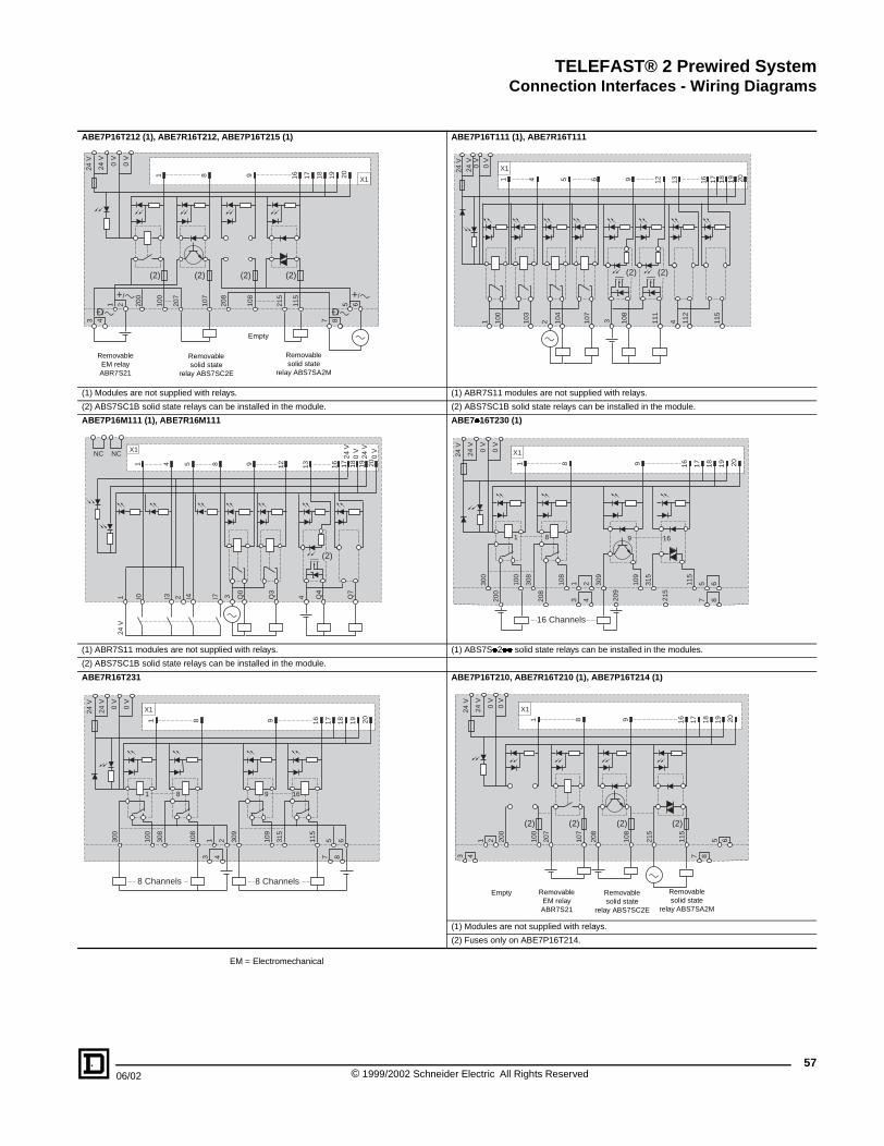
TELEFAST® 2 Prewired SystemConnection Interfaces - Wiring Diagrams
06/02
ABE7P16T212 (1), ABE7R16T212,
(1) Modules are not supplied with re
(2) ABS7SC1B solid state relays ca
ABE7P16M111 (1), ABE7R16M111
(1) ABR7S11 modules are not supp
(2) ABS7SC1B solid state relays ca
ABE7R16T231
1 8
0 V
0 V
24 V
24 V
3 4
1
2 200
100
107
207
(2) (2)
+/
Ð/
Removable EM relay ABR7S21
Removabsolid stat
relay ABS7S
124
V
I01 4
X1NC NC
I3 I425
3
1 8
X1
1 8
0 V
0 V
24 V
24 V
300
100
108
308
1
8 Channels
EM = Electromechanical
ABE7P16T215 (1) ABE7P16T111 (1), ABE7R16T111
lays. (1) ABR7S11 modules are not supplied with relays.
n be installed in the module. (2) ABS7SC1B solid state relays can be installed in the module.
ABE7�16T230 (1)
lied with relays. (1) ABS7S�2�� solid state relays can be installed in the modules.
n be installed in the module.
ABE7P16T210, ABE7R16T210 (1), ABE7P16T214 (1)
(1) Modules are not supplied with relays.
(2) Fuses only on ABE7P16T214.
16 17 18 19 209
X1
7 8
208
215
115
108
5
6
(2) (2)
+/
Ð/
le eC2E
Empty
Removable solid state
relay ABS7SA2M
1 100
111
112
115
4108
3107
1 4 6 12 1613 17 18 19 20
X10 V
0 V
24 V
24 V
103
104
2
5 9
(2) (2)Q
3
Q4
Q7
4Q0
3I78 12 1613 17
24 V
0 V
24 V
0 V
18 19 209
(2)
200
208
43 209
7 8215
1 16 17 18 19 2098
X1
1 8 9 16
0 V
0 V
24 V
24 V
300
100
108
308
309
21 315
115
109
65
16 Channels
4 7 8
16 17 18 19 209
9 16
309
2 315
115
109
65
8 Channels
3 4 7
8
1 16 17 18 19 2098
X1
(2) (2) (2) (2)
0 V
0 V
24 V
24 V
1
2 200
100
107
207
208
215
115
108
5
6
Removable EM relay ABR7S21
Removable solid state
relay ABS7SC2E
Removable solid state
relay ABS7SA2M
Empty
57© 1999/2002 Schneider Electric All Rights Reserved

TELEFAST® 2 Prewired SystemConnection Interfaces - Wiring Diagrams
58
ABE7P08T330 (1)
(1) Module is not supplied with relay
(2) Connection of ABS7SC3BA soli
ABE7P16T318 (1)
(1) Module is not supplied with relay
ABE7R16T332 (1), ABE7P16T332
(1) Module is not supplied with relay
(2) Required jumper supplied with r
ABR7S33
300
200
100
305
205
304
104
204
1 5
X10 V
0 V
24 V
24 V
AB
100
200
101
NC
201
1
X10 V
0 V
24 V
24 V
1 +/
RemovablEM relayABR7S33
Empty
1 2 3
1 4
X10 V
0 V
24 V
24 V
300
200
100
203
303
103
+/–/
RemovableEM relay ABR7S33
Empty
EM = Electromechanical
ABE7R16T330, ABE7P16T330 (1), ABE7P16T334 (1)
s. (1) Module is not supplied with relays.
d state relay. (2) Fuses only on ABE7P16T334.
(3) Connection of ABS7SC3BA solid state relay.
s.
s.
elay ABS7SC3BA.
307
107
207
106
206
306
105
6 7 8 17 18 19 20
S7SC3E
(2)
ABS7SA3M ABS7SC3BA ABR7S33
300
200
100
315
115
215
108
208
308
306
106
206
304
104
204
1 5 7 9 16 17 18 19 20
X10 V
0 V
24 V
24 V
ABS7SC3E
(3)
(2) (2) (2) (2)
ABS7SA3M ABS7SC3BA
102
202
NC
103
203
112
212
NC
NC
115
215
2 3 4 13 16 17 18 19 20
2 Ð
/
3 +/
4 Ð
/
5 +/
6 Ð
/
7 +/
8 Ð
/
e
Removable solid state relay
ABS7SC3Eonly
Removable solid state relay
ABS7SA3M
Empty 4 Channels 4 Channels Empty
54 6 7 8 9 10 11 12 1413 1615
5 8 9 12 1613 17 18 19 20
304
204
104
307
207
107
208
308
311
108
211
111
312
212
112
315
215
115
(2)+/–/ +/–/ +/–/
Removable solid state relay
ABS7SA3M
EmptyRemovable solid state relay ABS7SC3BA
Removable solid state relay
ABS7SC3Eonly
© 1999/2002 Schneider Electric All Rights Reserved 06/02

TELEFAST® 2 Prewired SystemConnection Interfaces - Wiring Diagrams
06/02
ABE7R16T370
ABE7P16F312 (1)
(1) Module is not supplied with relay
ABE7S16E2��
(1) The user must connect the prote
300
200
100
1
X1
1
0 V
0 V
24 V
24 V
600
500
400
16 Cha
NC
NC
100
200
203
103
21
1 4
X1
1 4
0 V
0 V
24 V
24 V
+/c
8 Chan
1 2 3 4 100
107
200
207
1 8
1 8
0 V
0 V
24 V
24 V
8 Channel
ABE7P16F310 (1)
(1) Module is not supplied with relays.
s.
ABE7S16S1B2/ABE7S16S2B0
ction fuse across terminals 1 and 2
315
115
215
16 17 18 19 20
16
615
415
515
nnels
NC
115
215
NC
100
200
1 17 18 19 20
X1
1
0 V
0 V
24 V
24 V
16
16
16 Channels21
1
111
112
212
215
115
NC
NC
3 4 65 7 8104
204
207
107
NC
NC
NC
NC
108
208
8 17 18 19 205 129
5 8 9 12 13 16
1613
Ð/c +/c Ð/c
nels 8 Channels
115
108
215
208
16 17 18 19 209
X1
9 16
8 Channel
1 2 3 4 100
107
115
108
200
207
215
208
1 16 17 18 19 2098
X1
1 8 9 16
0 V
0 V
24 V
24 V
(1)
8 Channel 8 Channel
59© 1999/2002 Schneider Electric All Rights Reserved

TELEFAST® 2 Prewired SystemConnection Interfaces - Wiring Diagrams
60
ABE7S08S2B0
(1) The user must connect the prote
ABE7CPA01
ABE7CPA03
(1) 25 mA limiter
1 32 4 100
200
1
1
0 V
0 V
24 V
24 V
(1) 8 Channel
0 V
0 V
24 V
24 V
28 2726
1 2 3 4 5 6 7 8 9 10 11
2 3 8 12 16 20 24 25 4 6 10 141
24 V
24 V 0 V
0 V
1 15
X1
200
(IS
0)
201
(IV
0)
1 2 3 4 100
(IS
1)
101
(1)(1)
8 currentinputs
8 voltageinputs
Channel 0
2-wire sensor
ABE7S08S2B1
ction fuse across terminals 1 and 2. (1) The user must connect the protection fuse across terminals 1 and 2
ABE7CPA02
107
207
13 17 18 19 208
X1
8
s
1 32 4 100
101
107
200
201
207
NC
NC
NC
NC
NC
1 13 17 18 19 2082
X1
1 2 8
0 V
0 V
24 V
24 V
NC
(1) 8 Channels
12 13 14 15 X1 1 2 3 4 5 6 7 8 9 X2
18 23 22 5 7 9 11 13 15 17 19 21 29 31 32 30 GN
DG
ND
NC
NC
252423222120191817161514131211
X1
10987654321
+
201
202
200
204
205
206
207
208
209
210
211
212
213
214
215
203
2 31 100
101
102
103
104
105
106
107
108
109
110
111
112
113
114
115
4
-
+-
+-
+-
8 voltageI/O
Channel 1
8 currentI/O
Channel 2
8 probe inputs PT100 Channel 4
Chan 6
Chan 8
2 16 3 9 12 13 4 18 5 19 14 17 20 23 7 21 8 22 10 24 11 256
202
(IC
0)
203
(0 V
)
204
(IS
2)
205
(IV
2)
(IV
1)
102
(IC
1)
103
104
(IS
3)
105
(IV
3)
106
(IC
3)
107
108
(IS
5)
109
(IV
5)
110
(IC
5)
111
112
(IS
7)
113
(IV
7)
114
(IC
7)
115
(1)(1)(1)(1)(1)(1)
206
(IC
2)
207
(0 V
)
208
(IS
4)
209
(IV
4)
210
(IC
4)
211
(0 V
)
212
(IS
6)
213
(IV
6)
214
(IC
6)
215
(0 V
)
Channel 2
Power Supply
Channel 5
4-wire sensor
© 1999/2002 Schneider Electric All Rights Reserved 06/02

TELEFAST® 2 Prewired SystemConnection Interfaces - Wiring Diagrams
06/02
ABE7CPA11
X1 To Premium module
X2 To Telefast
ABE7CPA21
ABE7CPA31
(1) 25 mA limiter
24 V
0 V
GN
D
1 2 3 45 V
123456789
101112131415
X1
Parallel Absolu
Internal logicpower supply
Internal
Address manadata seria
Absolute encode
252423222120191817161514131211
X1
10987654321
+
201
202
200
2 31 100
101
4
–
–
4 voltageI/O
Channel 1
4 currentI/O
Channel 2
24 V
24 V 0 V
0 V
21 14
100
(IS
0)
102
(IC
0)
1 2 3 4 101
(IV
0)
103
(0V
0)
(1)
a a
a
2-wire sensor
ABE7CPA12
(1) Temperature probe
(2) Used in cold junction compensation mode in the Telefast module
(3) Used in cold junction compensation mode by external 4-wire Pt100
21 22 23 24 25 26 27 28 29 30 31 32
123456789101112131415
X2
te Encoder
logic
gement andlization
r data interface
Encoderaddressinputs
204
205
206
207
203
102
103
104
105
106
107
+
252423222120191817161514131211
X1
10987654321
201
202
200
204
205
206
207
203
2 31 100
101
102
103
104
105
106
107
108
109
110
111
112
113
114
115
4
209
210
208
212
213
214
215
211
252423222120191817161514131211
X2
10987654321
(1)
(3)
(2)
4-wire Pt100
0 V
15 16 4 5 17 18 19 6 7 8 20 21 22 9 1110 23 24 25 12 133
104
(IS
1)
106
(IC
1)
108
(IS
2)
110
(IC
2)
105
(IV
1)
107
(0V
1)
109
(IV
2)
111
(0V
2)
113
(IV
3)
115
(0V
3)
117
(IV
4)
119
(0V
4)
123
(0V
5)
125
(IV
6)
127
(0V
6)
129
(IV
7)
131
(0V
7)
(1)(1)(1)(1)
112
(IS
3)
114
(IC
3)
116
(IS
4)
118
(IC
4)
120
(IS
5)
122
(IC
5)
124
(IS
6)
126
(IC
6)
128
(IS
7)
130
(IC
7)
121
(IV
5)
(1) (1) (1)
a a a
a a
a a
a a
a a
a a
Voltage sensor
Power Supply
4-wire Pt100
61© 1999/2002 Schneider Electric All Rights Reserved
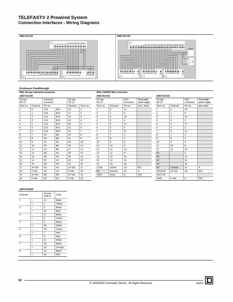
TELEFAST® 2 Prewired SystemConnection Interfaces - Wiring Diagrams
62
ABE7ACC02
Enclosure FeedthroughWith 40-way industrial connector
ABE7ACC80
20-wayHE 10
Industrialconnector
Term no. Channel Pin no.
1 0 C16
2 1 C15
3 2 C14
4 3 C13
5 4 C12
6 5 C11
7 6 C10
8 7 C9
9 8 C8
10 9 C7
11 10 C6
12 11 C5
13 12 D5
14 13 D6
15 14 D7
16 15 D8
17 24 Vdc A3
18 0 Vdc C3
19 24 Vdc B3
20 0 Vdc D3
ABFF25S200
Channel25-waySUB-D
1 – 14
+ 1
2 – 3
+ 15
3 – 17
+ 4
4 – 6
+ 18
5 – 20
+ 7
6 – 9
+ 21
7 – 23
+ 10
8 – 12
+ 24
B
A
1
1 2 3 4 5 6 7 8 9 10 11 12 13 14 15 16 17 18
ABE7ACC03
With CNOMO M23 connector
ABE7ACC82 ABE7ACC83
20-wayHE 10
20-wayHE 10
M23connector
Removablepower supply
20-wayHE 10
M23connector
Removablepower supply
Channel Term no. Term no. Channel Pin no. term. block Term no. Channel Pin no. term. block
B16 16 1 1 0 15 1 0 15
B15 17 2 2 1 5 2 1 5
B14 18 3 3 2 16 3 2 16
B13 19 4 4 3 3 4 3 3
B12 20 5 5 4 17 5 4 17
B11 21 6 6 5 2 6 5 2
B10 22 7 7 6 11 7 6 11
B9 23 8 8 7 1 8 7 1
B8 24 9 9 8 7 9 8 7
B7 25 10 10 9 4 10 9 4
B6 26 11 11 10 8 11 10 8
B5 27 12 12 11 14 12 11 14
A5 28 13 13 12 9 NC 9
A6 29 14 14 13 13 NC 13
A7 30 15 15 14 10 NC 10
A8 31 16 16 15 18 NC 18
A3 24 Vdc 17 17/19 24Vdc 19 B/C NC Ground 12 A
C3 0 Vdc 18 NC Ground 12 A 13/14/15/ 24 Vdc 19 B/C
B3 24 Vdc 19 18/20 0Vdc 6 D/E 16/17/19
D3 0 Vdc 20 18/20 0 Vdc 6 D/E
Color
Black
Yellow
Black
Blue
Black
Green
Black
White
Green
Red
Red
White
Black
Orange
Black
Red
C
2 3 4 5 6 7 8 9 10 11 12 13 14 15 16 17 18 19 20
19 20 1 2 3 4 5 6 7 8 9 16 17 18 19 20
1 2 3 4 5 9 10 11 12
A
13 14 15 16 17 18 19 20 21 22 23 24 25 26 27 28 29 30 31 32 33 34
1 2 3 4 5 6 7 8 9 20
B
1 2 3 4 5 6 7 8 9 20
C
1 2 3 4 5 6 7 8 9 20
Reset
6 7 8
D
© 1999/2002 Schneider Electric All Rights Reserved 06/02

TELEFAST® 2 Prewired SystemConnection Interfaces - Wiring Diagrams
06/02
ABE7TES160Input Connectors
Output Connectors
Input Connection Wiring
PLC
2
2
0 1
0123456
7
8910
11
12
13
14
15
0 1
2
2
0 1
0123456
7
8910
11
12
13
14
15
0 1
1
X1
1 2
0
0 V
0 V
24 V
24 V
1 2 3 84 107
100
5 76
Simulation Modules
Output Connection Wiring
16-input channel module 16-output channel module PLC
24 Vdc
Inserted between the PLC and the operative part, the simulation module is used to set the PLC inputs to 1 or 0 irrespective of the state of the operative part sensors.
2
2
0 1
0123456
7
8910
11
12
13
14
15
0 1
24 Vdc
Connected to a PLC input module, the simulation module enables signals to be forced to 1 or 0 and sensors to be connected to its screw terminals.
24 Vdc
Inserted between the PLC and the -operative part, the simulation module is used to set the operative part -actuators to 1 or 0 irrespective of the state of the PLC outputs.
16 17 18 19 20
115
108
1 16 17 18 19 20
X2
1 2
0
1 16 17 18 19 20
X1
1 2
0
0 V
0 V
24 V
24 V
1 2 3 8 115
108
4 107
100
5 76
1 16 17 18 19 20
X2
1 2
0
63© 1999/2002 Schneider Electric All Rights Reserved
TELEFAST® 2 Prewired SystemIndexed Catalog Numbers
ABC6HE20F . . . . . . . . . . . . . . . . . . . . . . . . . . . . .44ABE7ACC01 . . . . . . . . . . . . . . . . . . . . . . . . . . . . .43ABE7ACC02 . . . . . . . . . . . . . . . . . . . . . . . . . . . . .43ABE7ACC03 . . . . . . . . . . . . . . . . . . . . . . . . . . . . .45ABE7ACC04 . . . . . . . . . . . . . . . . . . . . . . . . . . . . .46ABE7ACC05 . . . . . . . . . . . . . . . . . . . . . . . . . . . . .46ABE7ACC10 . . . . . . . . . . . . . . . . . . . . . . . . . . . . .43ABE7ACC11 . . . . . . . . . . . . . . . . . . . . . . . . . . . . .43ABE7ACC12 . . . . . . . . . . . . . . . . . . . . . . . . . . . . .41ABE7ACC20 . . . . . . . . . . . . . . . . . . . . . . . . . . . . .43ABE7ACC21 . . . . . . . . . . . . . . . . . . . . . . . . . . . . .43ABE7ACC30 . . . . . . . . . . . . . . . . . . . . . . . . . . . . .43ABE7ACC80 . . . . . . . . . . . . . . . . . . . . . . . . . . . . .43ABE7ACC81 . . . . . . . . . . . . . . . . . . . . . . . . . . . . .43ABE7ACC82 . . . . . . . . . . . . . . . . . . . . . . . . . . . . .43ABE7ACC83 . . . . . . . . . . . . . . . . . . . . . . . . . . . . .43ABE7ACC84 . . . . . . . . . . . . . . . . . . . . . . . . . . . . .43ABE7ACC85 . . . . . . . . . . . . . . . . . . . . . . . . . . . . .43ABE7BV10. . . . . . . . . . . . . . . . . . . . . . . . . . . . . . .43ABE7BV20. . . . . . . . . . . . . . . . . . . . . . . . . . . . . . .43ABE7CPA01. . . . . . . . . . . . . . . . . . . . . . . . . . . . . .42ABE7CPA02. . . . . . . . . . . . . . . . . . . . . . . . . . . . . .42ABE7CPA03. . . . . . . . . . . . . . . . . . . . . . . . . . . . . .42ABE7CPA11. . . . . . . . . . . . . . . . . . . . . . . . . . . . . .42ABE7CPA12. . . . . . . . . . . . . . . . . . . . . . . . . . . . . .42ABE7CPA13. . . . . . . . . . . . . . . . . . . . . . . . . . . . . .42ABE7CPA21. . . . . . . . . . . . . . . . . . . . . . . . . . . . . .42ABE7CPA31. . . . . . . . . . . . . . . . . . . . . . . . . . . . . .42ABE7FU012. . . . . . . . . . . . . . . . . . . . . . . . . . . . . .43ABE7FU050. . . . . . . . . . . . . . . . . . . . . . . . . . . . . .43ABE7FU100. . . . . . . . . . . . . . . . . . . . . . . . . . . . . .43ABE7FU200. . . . . . . . . . . . . . . . . . . . . . . . . . . . . .43ABE7FU400. . . . . . . . . . . . . . . . . . . . . . . . . . . . . .43ABE7FU630. . . . . . . . . . . . . . . . . . . . . . . . . . . . . .43ABE7H08R10 . . . . . . . . . . . . . . . . . . . . . . . . . . . .37ABE7H08R11 . . . . . . . . . . . . . . . . . . . . . . . . . . . .37ABE7H08R21 . . . . . . . . . . . . . . . . . . . . . . . . . . . .37ABE7H08S21 . . . . . . . . . . . . . . . . . . . . . . . . . . . .37ABE7H12R10 . . . . . . . . . . . . . . . . . . . . . . . . . . . .37ABE7H12R11 . . . . . . . . . . . . . . . . . . . . . . . . . . . .37ABE7H12R20 . . . . . . . . . . . . . . . . . . . . . . . . . . . .37ABE7H12R21 . . . . . . . . . . . . . . . . . . . . . . . . . . . .37ABE7H12R50 . . . . . . . . . . . . . . . . . . . . . . . . . . . .37ABE7H12S21 . . . . . . . . . . . . . . . . . . . . . . . . . . . .37ABE7H16C10 . . . . . . . . . . . . . . . . . . . . . . . . . . . .36ABE7H16C11 . . . . . . . . . . . . . . . . . . . . . . . . . . . .36ABE7H16C21 . . . . . . . . . . . . . . . . . . . . . . . . . . . .36ABE7H16C31 . . . . . . . . . . . . . . . . . . . . . . . . . . . .36ABE7H16CM11. . . . . . . . . . . . . . . . . . . . . . . . . . .36ABE7H16CM21. . . . . . . . . . . . . . . . . . . . . . . . . . .36ABE7H16F43. . . . . . . . . . . . . . . . . . . . . . . . . . . . .37ABE7H16R10 . . . . . . . . . . . . . . . . . . . . . . . . . . . .37ABE7H16R11 . . . . . . . . . . . . . . . . . . . . . . . . . . . .37ABE7H16R20 . . . . . . . . . . . . . . . . . . . . . . . . . . . .37ABE7H16R21 . . . . . . . . . . . . . . . . . . . . . . . . . . . .37ABE7H16R23 . . . . . . . . . . . . . . . . . . . . . . . . . . . .37ABE7H16R30 . . . . . . . . . . . . . . . . . . . . . . . . . . . .37ABE7H16R31 . . . . . . . . . . . . . . . . . . . . . . . . . . . .37ABE7H16R50 . . . . . . . . . . . . . . . . . . . . . . . . . . . .37ABE7H16S21 . . . . . . . . . . . . . . . . . . . . . . . . . . . .37ABE7H16S43 . . . . . . . . . . . . . . . . . . . . . . . . . . . .37ABE7H20E100 . . . . . . . . . . . . . . . . . . . . . . . . . . .36ABE7H20E200 . . . . . . . . . . . . . . . . . . . . . . . . . . .36ABE7H20E300 . . . . . . . . . . . . . . . . . . . . . . . . . . .36ABE7H32E150 . . . . . . . . . . . . . . . . . . . . . . . . . . .36ABE7H32E300 . . . . . . . . . . . . . . . . . . . . . . . . . . .36ABE7LOGF25. . . . . . . . . . . . . . . . . . . . . . . . . . . .43ABE7LOGV10. . . . . . . . . . . . . . . . . . . . . . . . . . . .43ABE7P08T330. . . . . . . . . . . . . . . . . . . . . . . . . . . .40ABE7P16F310. . . . . . . . . . . . . . . . . . . . . . . . . . . .39ABE7P16F312. . . . . . . . . . . . . . . . . . . . . . . . . . . .39ABE7P16M111 . . . . . . . . . . . . . . . . . . . . . . . . . . .40ABE7P16T111. . . . . . . . . . . . . . . . . . . . . . . . . . . .40ABE7P16T210. . . . . . . . . . . . . . . . . . . . . . . . . . . .40ABE7P16T212. . . . . . . . . . . . . . . . . . . . . . . . . . . .40ABE7P16T214. . . . . . . . . . . . . . . . . . . . . . . . . . . .40ABE7P16T215. . . . . . . . . . . . . . . . . . . . . . . . . . . .40ABE7P16T230. . . . . . . . . . . . . . . . . . . . . . . . . . . .40ABE7P16T318. . . . . . . . . . . . . . . . . . . . . . . . . . . .40ABE7P16T330. . . . . . . . . . . . . . . . . . . . . . . . . . . .40ABE7P16T332. . . . . . . . . . . . . . . . . . . . . . . . . . . .40ABE7P16T334. . . . . . . . . . . . . . . . . . . . . . . . . . . .40ABE7R08S111 . . . . . . . . . . . . . . . . . . . . . . . . . . .38ABE7R08S210 . . . . . . . . . . . . . . . . . . . . . . . . . . .38ABE7R08S216 . . . . . . . . . . . . . . . . . . . . . . . . . . .38ABE7R16M111. . . . . . . . . . . . . . . . . . . . . . . . . . .39ABE7R16S111 . . . . . . . . . . . . . . . . . . . . . . . . . . .38ABE7R16S210 . . . . . . . . . . . . . . . . . . . . . . . . . . .38ABE7R16S212 . . . . . . . . . . . . . . . . . . . . . . . . . . .38ABE7R16T111 . . . . . . . . . . . . . . . . . . . . . . . . . . .39ABE7R16T210 . . . . . . . . . . . . . . . . . . . . . . . . . . .39
ABE7R16T212. . . . . . . . . . . . . . . . . . . . . . . . . . . 39ABE7R16T230. . . . . . . . . . . . . . . . . . . . . . . . . . . 39ABE7R16T231. . . . . . . . . . . . . . . . . . . . . . . . . . . 39ABE7R16T330. . . . . . . . . . . . . . . . . . . . . . . . . . . 39ABE7R16T332. . . . . . . . . . . . . . . . . . . . . . . . . . . 39ABE7R16T370. . . . . . . . . . . . . . . . . . . . . . . . . . . 39ABE7S08S2B0. . . . . . . . . . . . . . . . . . . . . . . . . . . 38ABE7S08S2B1. . . . . . . . . . . . . . . . . . . . . . . . . . . 38ABE7S16E2B1. . . . . . . . . . . . . . . . . . . . . . . . . . . 38ABE7S16E2E0. . . . . . . . . . . . . . . . . . . . . . . . . . . 38ABE7S16E2E1. . . . . . . . . . . . . . . . . . . . . . . . . . . 38ABE7S16E2F0. . . . . . . . . . . . . . . . . . . . . . . . . . . 38ABE7S16E2M0 . . . . . . . . . . . . . . . . . . . . . . . . . . 38ABE7S16S1B2. . . . . . . . . . . . . . . . . . . . . . . . . . . 38ABE7S16S2B0. . . . . . . . . . . . . . . . . . . . . . . . . . . 38ABE7TES160. . . . . . . . . . . . . . . . . . . . . . . . . . . . 43ABFA32H151 . . . . . . . . . . . . . . . . . . . . . . . . . . . . 47ABFA32H200 . . . . . . . . . . . . . . . . . . . . . . . . . . . . 47ABFA32H300 . . . . . . . . . . . . . . . . . . . . . . . . . . . . 47ABFA32H301 . . . . . . . . . . . . . . . . . . . . . . . . . . . . 47ABFB25S201 . . . . . . . . . . . . . . . . . . . . . . . . . . . . 45ABFB25S301 . . . . . . . . . . . . . . . . . . . . . . . . . . . . 45ABFB50S201 . . . . . . . . . . . . . . . . . . . . . . . . . . . . 45ABFB50S301 . . . . . . . . . . . . . . . . . . . . . . . . . . . . 45ABFC08R02B. . . . . . . . . . . . . . . . . . . . . . . . . . . . 43ABFC08R02R. . . . . . . . . . . . . . . . . . . . . . . . . . . . 43ABFC08R02W . . . . . . . . . . . . . . . . . . . . . . . . . . . 43ABFC08R12B. . . . . . . . . . . . . . . . . . . . . . . . . . . . 43ABFC08R12R. . . . . . . . . . . . . . . . . . . . . . . . . . . . 43ABFC08R12W . . . . . . . . . . . . . . . . . . . . . . . . . . . 43ABFC20R200. . . . . . . . . . . . . . . . . . . . . . . . . . . . 44ABFF25S200 . . . . . . . . . . . . . . . . . . . . . . . . . . . . 44ABFF25S200 . . . . . . . . . . . . . . . . . . . . . . . . . . . . 51ABFH14H150. . . . . . . . . . . . . . . . . . . . . . . . . . . . 51ABFH14H300. . . . . . . . . . . . . . . . . . . . . . . . . . . . 51ABFH16H150. . . . . . . . . . . . . . . . . . . . . . . . . . . . 51ABFH16H300. . . . . . . . . . . . . . . . . . . . . . . . . . . . 51ABFH20H100. . . . . . . . . . . . . . . . . . . . . . . . . . . . 44ABFH20H151. . . . . . . . . . . . . . . . . . . . . . . . . . . . 45ABFH20H200. . . . . . . . . . . . . . . . . . . . . . . . . . . . 44ABFH20H201. . . . . . . . . . . . . . . . . . . . . . . . . . . . 45ABFH20H300. . . . . . . . . . . . . . . . . . . . . . . . . . . . 44ABFH20H301. . . . . . . . . . . . . . . . . . . . . . . . . . . . 45ABFH20H501. . . . . . . . . . . . . . . . . . . . . . . . . . . . 45ABFH28H150. . . . . . . . . . . . . . . . . . . . . . . . . . . . 51ABFH28H300. . . . . . . . . . . . . . . . . . . . . . . . . . . . 51ABFH32H150. . . . . . . . . . . . . . . . . . . . . . . . . . . . 51ABFH32H300. . . . . . . . . . . . . . . . . . . . . . . . . . . . 51ABFH34H100. . . . . . . . . . . . . . . . . . . . . . . . . . . . 45ABFH34H200. . . . . . . . . . . . . . . . . . . . . . . . . . . . 45ABFH34H300. . . . . . . . . . . . . . . . . . . . . . . . . . . . 45ABFH40H150. . . . . . . . . . . . . . . . . . . . . . . . . . . . 50ABFH40H151. . . . . . . . . . . . . . . . . . . . . . . . . . . . 50ABFH40H300. . . . . . . . . . . . . . . . . . . . . . . . . . . . 50ABFH40H301. . . . . . . . . . . . . . . . . . . . . . . . . . . . 50ABFM04S200. . . . . . . . . . . . . . . . . . . . . . . . . . . . 49ABFM04S201. . . . . . . . . . . . . . . . . . . . . . . . . . . . 49ABFM08S201. . . . . . . . . . . . . . . . . . . . . . . . . . . . 49ABFM08S202. . . . . . . . . . . . . . . . . . . . . . . . . . . . 49ABFM16H150. . . . . . . . . . . . . . . . . . . . . . . . . . . . 48ABFM16H151. . . . . . . . . . . . . . . . . . . . . . . . . . . . 48ABFM16H300. . . . . . . . . . . . . . . . . . . . . . . . . . . . 48ABFM16H301. . . . . . . . . . . . . . . . . . . . . . . . . . . . 48ABFM16S201. . . . . . . . . . . . . . . . . . . . . . . . . . . . 49ABFM32H150. . . . . . . . . . . . . . . . . . . . . . . . . . . . 49ABFM32H151. . . . . . . . . . . . . . . . . . . . . . . . . . . . 49ABFM32H300. . . . . . . . . . . . . . . . . . . . . . . . . . . . 49ABFM32H301. . . . . . . . . . . . . . . . . . . . . . . . . . . . 49ABFR16H200. . . . . . . . . . . . . . . . . . . . . . . . . . . . 50ABFR16H201. . . . . . . . . . . . . . . . . . . . . . . . . . . . 50ABFS08H202 . . . . . . . . . . . . . . . . . . . . . . . . . . . . 51ABFS08H203 . . . . . . . . . . . . . . . . . . . . . . . . . . . . 51ABFS16H200 . . . . . . . . . . . . . . . . . . . . . . . . . . . . 51ABFS24H200 . . . . . . . . . . . . . . . . . . . . . . . . . . . . 51ABFS25S301 . . . . . . . . . . . . . . . . . . . . . . . . . . . . 45ABFS25S302 . . . . . . . . . . . . . . . . . . . . . . . . . . . . 47ABFY25S200 . . . . . . . . . . . . . . . . . . . . . . . . . . . . 44ABR7S11. . . . . . . . . . . . . . . . . . . . . . . . . . . . . . . . 41ABR7S21. . . . . . . . . . . . . . . . . . . . . . . . . . . . . . . . 41ABR7S23. . . . . . . . . . . . . . . . . . . . . . . . . . . . . . . . 41ABR7S33. . . . . . . . . . . . . . . . . . . . . . . . . . . . . . . . 41ABR7S33E . . . . . . . . . . . . . . . . . . . . . . . . . . . . . . 41ABR7S37. . . . . . . . . . . . . . . . . . . . . . . . . . . . . . . . 41ABS7EA3E5. . . . . . . . . . . . . . . . . . . . . . . . . . . . . 41ABS7EA3F5 . . . . . . . . . . . . . . . . . . . . . . . . . . . . . 41ABS7EA3M5. . . . . . . . . . . . . . . . . . . . . . . . . . . . . 41ABS7EC3AL. . . . . . . . . . . . . . . . . . . . . . . . . . . . . 41ABS7EC3B2. . . . . . . . . . . . . . . . . . . . . . . . . . . . . 41ABS7EC3E2. . . . . . . . . . . . . . . . . . . . . . . . . . . . . 41ABS7SA2M. . . . . . . . . . . . . . . . . . . . . . . . . . . . . . 41ABS7SA3M. . . . . . . . . . . . . . . . . . . . . . . . . . . . . . 41
ABS7SC1B . . . . . . . . . . . . . . . . . . . . . . . . . . . . . .41ABS7SC2E . . . . . . . . . . . . . . . . . . . . . . . . . . . . . .41ABS7SC3BA . . . . . . . . . . . . . . . . . . . . . . . . . . . . .41ABS7SC3E . . . . . . . . . . . . . . . . . . . . . . . . . . . . . .41AR1SB3 . . . . . . . . . . . . . . . . . . . . . . . . . . . . . . . . .43TSXBLK71. . . . . . . . . . . . . . . . . . . . . . . . . . . . . . .45TSXBLK81. . . . . . . . . . . . . . . . . . . . . . . . . . . . . . .45TSXBLK91. . . . . . . . . . . . . . . . . . . . . . . . . . . . . . .45TSXCAP030 . . . . . . . . . . . . . . . . . . . . . . . . . . . . .44TSXCCPH15. . . . . . . . . . . . . . . . . . . . . . . . . . . . .44TSXCCPS15 . . . . . . . . . . . . . . . . . . . . . . . . . . . . .44TSXCDP053 . . . . . . . . . . . . . . . . . . . . . . . . . . . . .44TSXCDP103 . . . . . . . . . . . . . . . . . . . . . . . . . . . . .44TSXCDP203 . . . . . . . . . . . . . . . . . . . . . . . . . . . . .44TSXCDP301 . . . . . . . . . . . . . . . . . . . . . . . . . . . . .44TSXCDP303 . . . . . . . . . . . . . . . . . . . . . . . . . . . . .44TSXCDP501 . . . . . . . . . . . . . . . . . . . . . . . . . . . . .44TSXCDP503 . . . . . . . . . . . . . . . . . . . . . . . . . . . . .44TSXCXP213 . . . . . . . . . . . . . . . . . . . . . . . . . . . . .44TSXCXP613 . . . . . . . . . . . . . . . . . . . . . . . . . . . . .44
© 1999/2000 Schneider Electric All Rights Reserved64
06/02

TELEFAST® 2 Prewired System
65
© 1999/2002 Schneider Electric All Rights Reserved 06/02
TELEFAST® 2 Prewired System
66
© 1999/2002 Schneider Electric All Rights Reserved 06/02
TELEFAST® 2 Prewired System
06/02
67© 1999/2002 Schneider Electric All Rights Reserved

Catalog No. 8501CT9801R2/02 June 2002 © 1999–2002 Schneider Electric All Rights Reserved Replaces 8501CT9801 dated 05/99
Square D Company8001 Highway 64 EastKnightdale, NC 275451-888-SquareD(1-888-778-2733)www.SquareD.com
Schneider Canada Inc.19 Waterman Avenue, M4B 1 Y2Toronto, Ontario1-800-565-6699www.schneider-electric.ca