Embed Size (px)
Citation preview

Submitted to PASP
Telescope Fabra ROA Montsec: a new robotic wide-field Baker-Nunn facility
Octavi Fors1,2
Jorge Nunez1,2 and Jose Luis Muinos3
Francisco Javier Montojo3 and Roberto Baena-Galle1,2
Jaime Boloix3 and Ricardo Morcillo3 and Marıa Teresa Merino1,2
Elwood C. Downey4 and Michael J. Mazur5
ABSTRACT
A Baker-Nunn Camera (BNC), originally installed at the Real Instituto y Observato-
rio de la Armada (ROA) in 1958, was refurbished and robotized. The new facility, called
Telescope Fabra ROA Montsec (TFRM), was installed at the Observatori Astronomic
del Montsec (OAdM).
The process of refurbishment is described in detail. Most of the steps of the re-
furbishment project were accomplished by purchasing commercial components, which
involve little posterior engineering assembling work. The TFRM is a 0.5m aperture
f/0.96 optically modified BNC, which offers a unique combination of instrumental spec-
ifications: fully robotic and remote operation, wide-field of view (4.◦4×4.◦4), moderate
limiting magnitude (V∼19.5 mag), ability of tracking at arbitrary right ascension (α)
and declination (δ) rates, as well as opening and closing CCD shutter at will during an
exposure.
Nearly all kind of image survey programs can benefit from those specifications.
Apart from other less time consuming programs, since the beginning of science TFRM
operations we have been conducting two specific and distinct surveys: super-Earths
1Observatori Fabra, Reial Academia de Ciencies i Arts de Barcelona. Rambla dels Estudis, 115. 08002. Barcelona.
Spain.
2Departament d’Astronomia i Meteorologia and Institut de Ciencies del Cosmos (ICC), Universitat de Barcelona
(UB/IEEC). Martı i Franques 1. 08028. Barcelona. Spain.
3Real Instituto y Observatorio de la Armada. Plaza de las Marinas s/n, 11110. San Fernando (Cadiz), Spain.
4Clear Sky Institute Inc., USA
5Hygga Innovative Technologies Inc., Norway
arX
iv:1
211.
5581
v4 [
astr
o-ph
.IM
] 9
Apr
201
3

– 2 –
transiting around M-type dwarfs stars, and geostationary debris in the context of Space
Situational Awareness / Space Surveillance and Tracking (SSA/SST) programs. Pre-
liminary results for both cases will be shown.
Subject headings: Telescopes: individual(Baker-Nunn Camera) - Surveys - Planets and
satellites: detection - Astrometry: individual(Space debris)
1. INTRODUCTION
With the launch of Sputnik 1 in the fall of 1957 and other pioneering artificial satellites few
months later, the early Space Age was born. As a solution for optically tracking these new satel-
lites, the Smithsonian Institution designed and constructed a new kind of telescope: the Baker-Nunn
Camera (BNC) (Henize 1957). The effort invested in such challenging project yielded a cutting
edge prototype, both in terms of technology and optics specifications in that epoch. As a result
of those outstanding specifications, the BNC was able to achieve satellite positional measurements
with a typical accuracy of ∼2′′ for one single station. It is in the context of the International
Geophysical Year, that these measurements allowed to determine for the first time important geo-
physical quantities, such as the upper atmosphere drag in satellites orbits, the Earth flattening, the
radial distribution of Earth mass, etc.
In order to maximize the satellites coverage and minimize the positional measurement error,
a family of 21 BNCs were manufactured in two releases and placed all over the world spanning
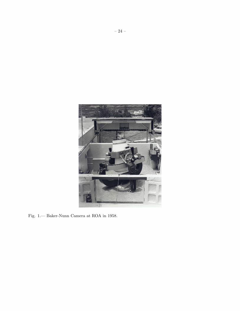
in longitude. In 1958 one of them was installed at ROA (see Fig. 1), in San Fernando (Cadiz),
southern Spain.
With the upcoming of new satellite tracking technologies on the early 80s, a new kind of
facilities called Ground Based-Electro-Optical Deep Space Surveillance (GEODSS) (Jeas & Anctil
1981) were designed, manufactured and installed, so that the BNC program became obsolete and
was cancelled. The BNC in San Fernando was donated to ROA, where it was maintained inactive
but in excellent state of conservation.
We report here on the refurbishment process of the BNC at ROA, renamed as Telescope Fabra
ROA Montsec (TFRM). The new telescope designation stands for the two partner institutions of
the consortium: Reial Academia de Ciencies i Arts de Barcelona (RACAB) - Observatori Fabra,
and Real Instituto y Observatorio de la Armada (ROA), as well as the observing site: Observatori
Astronomic del Montsec (OAdM). In summary, the differences between the original BNC at ROA
and the TFRM are: a new motorized equatorial mount, the substitution of the photographic film
with a CCD as a detector, the addition of corrective optics to flatten the CCD field of view (FoV),
and the control software which commands every device of the observatory and formalizes the robotic
concept by scheduling the observing tasks to be executed every night.
In § 2 we present in detail the refurbishment process step-by-step with a description of the

– 3 –
specifications of the original BNC at ROA given in § 2.1, the specifications of refurbished TFRM
in § 2.2, and the observing site in § 2.3. In § 2.4, the reproducibility of the refurbishment process
for other BNCs is evaluated.
In § 3 we show the observational capabilities of the TFRM. In particular, some demostrative
results of the system performance are given in the context of an exoplanet survey and a space
debris survey. Other programs such as surveying the Space Situational Awareness/NEO-segment
(SSA/NEO), or monitoring GRBs, γ-ray binaries, AGNs, blazars, etc. are also discussed.
In § 4 we summarize the refurbishment project and TFRM performance after one year of
science operations. We also discuss the know-how accumulated during the process, and lessons
learnt in view of improving reproducibility for other inactive BNCs.
2. REFURBISHMENT PROCESS
The Telescope Fabra ROA Montsec (TFRM) is a consortium that was created to develop and
operate a refurbished BNC (see http://www.am.ub.edu/bnc for updated details).
An extensive refurbishment project was conducted using the BNC originally installed at ROA,
which successfully culminated in the TFRM, a wide-field CCD facility with remote and robotic
capabilities. In several aspects, our refurbishment project learnt from the previous experience of
the Automated Patrol Telescope (Carter et al. 1992), the Phoenix BNC (Law et al. 2002), and the
Rothney Astrophysical Observatory (RAO) BNC (Mazur et al. 2005). We placed special emphasis
on the last one, as two of us (RB-G and MTM) performed a number of research stays at RAO and
one of us (MJM), participated in the refurbishment of the RAO BNC. This allowed us to be more
innovative with a number of parts of the project (see § 2.2), and sped up the learning curve of those
parts which were identical. In addition, another refurbishment project for the Indian BNC, called
ARIES (Gupta et al. 2005), was planned.
However, it is worth noting that, as far as we know, none of the refurbished BNCs have the
ability of being robotically and/or remotely commanded. Among others, this is the most important
difference between those and our BNC.
2.1. Specifications of pre-refurbished BNC
The Baker-Nunn Camera is named after the two pioneering engineers responsible for its optical
and mechanical design, Dr. James G. Baker and Joseph Nunn, respectively.
Optically, the BNC was designed as an f/1 system with 0.5 m three-element lenses corrector
cell, and a 0.78 m diameter primary spherical mirror (i.e. modified Schmidt telescope). The two
outside surfaces of corrector cell are spherical, while the other four inner ones are aspherical. The

– 4 –
four aspherics are not different each other, but identical in pairs. The main difference between
the BNC and a classical Schmidt system is that the inner aspherical surfaces have more refractive
power, which is necessary for a system as fast as f/1. This, however, adds aberrations that must be
accounted for. To correct this chromatic aberration Dr. Baker made use of a combination of exotic
glasses: Schott KzFS-2 and Schott SK-14 for the outer and inner elements, respectively. And, as
with a Schmidt camera, the focal surface is non-planar. Along this near spherical focal surface
ran a 55 mm wide Cinemascope photographic film providing a roughly 30◦x5◦ FoV. The optical
prescription of the original BNC can be found in Table 1, as described in Baker (1962). A drawing
of the optical layout for such prescription is shown in Fig. 2.
Mechanically, the BNC was designed to sit on a triangular base. As seen in Fig. 1, mounted
on that base there was a 360◦ rotating fork. A gimbal ring was mounted over this fork, so that
it could rotate ±80◦ in elevation. The optical tube assembly was mounted on the center of the
gimbal ring. The tube could be motor driven ±70◦ in a 2nd elevation axis that is 90◦ to the 1st
elevation axis. Although complex in design, this balanced alt-alt-az mount could be positioned to
track across any angular direction in the sky - a necessity for early satellite tracking programs.
When in observing mode, the film was supplied from a large film canister attached to the
telescope, stretched over the focal surface, exposed and then reeled into a take-up canister on the
opposite side of the telescope. Two synchronized, rotating shutters allowed for the trailed images
to be chopped and timestamped with data provided from the BNC signal clock.
The primary mirror was suspended inside its cell following an innovative design, which was
pioneering before the upcoming of active optics in the 80s. As seen in Fig. 3, the mirror cell
employed a series of cylindrical counterweights and a ’floating’ mirror which was coupled to the
focal surface through 3 Invar rods. These features helped the BNC maintain focus throughout its
entire pointing range and over a large range of temperatures.
Perkin & Elmer Corp. was the contractor and manufacturer for the optical grinding, polish-
ing, and figure testing. Boller & Chivens manufactured the mechanical parts, and performed the
assembly and final testings.
As a result of the outstanding optical and mechanical designs and the excellent manufacturing
process mentioned above, an extremely high set of optical and mechanical specifications were met.
In particular, it was guaranteed that 80% of encircled energy of incoming light from UV to deep
red was projected within a 20µm spot size throughout the 30◦x5◦ FoV covered by the photographic
film.
2.2. Specifications of post-refurbished BNC
On September 23rd of 2009, the (partly) refurbished BNC saw first light at the ROA during a
test of its mount and assessment of the corrector and lens quality. The first images were taken under

– 5 –
non-ideal conditions: urban light polluted skies, unpolished 50cm outermost lens, non-recoated
mirror, and uncollimated optics. Despite these drawbacks, the quality of the first images was very
promising. These results were then reconfirmed with the first technical light at the final observing
site (Observatori Astronomic del Montsec, OAdM), which was performed on September 11th 2010,
after mirror recoating, outermost lens repolishing and preliminary collimation of the optical system.
As seen in Fig. 4, the quality is excellent giving the instrument a great deal of scientific potential.
A few days later, on 16 Sep 2010, the TFRM was inaugurated (Fors et al. 2010a,b). Fig. 5
shows the observatory as it looks now, after conclusion of the refurbishment project. As a result of
this work, the TFRM offers a unique combination of instrumental specifications, namely: a large
FoV (4.◦4×4.◦4), scale of 3.9′′/pixel, a moderate limiting magnitude (V∼19.5 mag), the capability
of tracking at arbitrary α and δ rates, and the ability to command the CCD camera shutter at
will during an exposure. All-in-all, together with its robotic and remote operations, the TFRM is
strongly suited to conduct observational survey programs (see § 3).
The refurbishment process can be summarized in the following steps:
2.2.1. Mount modification
As described in § 2.1, the original mount design of the BNC had 3 rotational axes (alt-alt-az).
For reasons of reliability and operatibility, it was decided to convert the mount to a 2-axis
setup. In deciding how to proceed, we considered approaches that had been successfully applied
during other BNC refurbishments:
1. the Automated Patrol Telescope removed the original azimuth base, built a new pier and
tilted the yoke in accordance with the site latitude,
2. the RAO BNC kept the original azimuth base and tilted this according the latitude for setting
the α axis. In addition, the fork was cut so that original altitude axis is now used as declination
axis.
The first option is convenient because of its simplicity, specifically for low to moderate latitude
sites, where the installation of a yoke-mounted BNC would be feasible. However, it also imposes
restrictions when observing areas close to the celestial pole. On the other hand, the second alter-
native requires a major (and more expensive) transformation of the fork. However, it would be the
natural choice for a high latitude site where the first approach would not be feasible due to the
possibility of tube-mount interference.
Apart from our moderate latitude site, an additional reason led us towards the first approach:
the azimuth fork in early BNCs (like APT and TFRM) was supported by a simple manual bearing
assembly. Later BNCs designs (like the RAO’s), however, incorporated a motorized, side-loadable

– 6 –
bearing assembly which could be driven while inclined. Finally, the mount was modified with an
adjustable inclination range of ±5◦, which spans the latitudes of the ROA, testing site, and the
OAdM, the final observing site.
Other refurbished mount alternatives such as operating in alt-azimuth or buying a new mount
were discarded because of operational difficulties and cost, respectively.
Once the BNC mount was converted to equatorial mode, both α and δ axes needed to be
motorized such that they could be commanded from the control computer. As the newly modified
α axis lacked a gearing mechanism, a new 180-teeth gear was machined. A design identical to the
original gear in the new δ axis was chosen. In addition, a new worm screw for the α axis was
machined as a copy of the δ worm screw, which was already present in former orbital axis.
The mount conversion and the manufacture of the α gear was performed by Talleres Yeste S.L.
(Cadiz, Spain).
Finally, NEMA-234 brushless motors controlled by BearingEngineers AVS digital servo drives
were installed on the α and δ axes. The telescope closed-loop motion was completed with the
following devices:
1. two 25-bit Heidenhain ECN 225 absolute angle encoders directly installed on each axis shaft
and interfaced via a TCP/IP Heidenhain EIB-741 unit,
2. a Pro-Dex PC48 Multi-Axis Motion Controller board plugged on the control computer. A
number of devices of the observatory (α and δ motors, focus drive, etc.) can be controlled
from this board,
3. a Meinberg LANTIME M200/GPS time server which allows to synchronize and timestamp
UTC time on whatever observatory device via NTP protocol with an accuracy of ±0.1 ms
(limited by CAT6 LAN latency).
2.2.2. New precise spider and focus system
A key aspect of the retrofit process is the fabrication of the enclosure and spider assembly to
house the CCD camera and the focus system. All of which sits inside the Baker-Nunn camera tube.
Because of the f/1 nature of the BNC, a ±10µm repeatability or better focus is required to fully
realize the resolution inherent in the optical system.
The solution to these requirements was as follows:
1. a preliminary design for a tilt/rotate camera support assembly was provided by MJM based
on his experience with the refurbishment of the RAO BNC.

– 7 –
2. the final, optimized design was developed and fabricated by Moreno Pujal S.L. (Barcelona,
Spain), as can be seen in Fig. 6. This consists on a steel vane assembly that attaches to a
central focus housing. That is a cylindrical steel shell containing the focus mechanics and
motor. The CCD camera housing is attached to the end of a triple-contact focusing ram. At
the bottom of the CCD housing a cell keeps the meniscus lens at the prescribed distance to
the CCD chip. The whole assembly is attached to four spider vanes which are attached to
the TFRM midtube section. Further, precise alignment of the camera with respect to the
optical axis of the telescope is performed using rotational and tip-tilt adjusters installed in
the midtube section. These adjusters have a tip-tilt resolution of 3µm, a rotational resolution
of 43′′, and radial resolution of 63µm.
A remarkable feature of the design specified by Moreno Pujal S.L. is the capability of removing
the central focus and CCD housings without touching the spider vanes. This requirement helps
ensure optimal aligment of the whole assembly when the central cylinder needs to be removed for
maintainance. Operational experience since Sep 2010 indicates that such a specification has been
met: for the four times that the cylindrical housing has been removed for upgrading purposes, only
small variations on the collimation of the system were noted upon reassembly. This means that
relatively few hours have been needed for recollimation after dismantling/reassembling the BNC
camera housing unit.
Another critical specification was that the spider vanes and focus system be as athermal as
possible. In other words, with an f/1 system we could not afford to have focus changes larger
than ±10µm due to temperature changes, difference in telescope attitude, etc. The focus stability
after two years of science operations has shown outstanding performance: not only is the focus
adjustment unnecessary during a given night, but we have realized that focus can be maintained
unchanged during months with no loss in faintest object detection.
Finally, the inclusion of two baffles between the meniscus and CCD shutter and the coating
of the internal sides of the CCD housing with an special ultra-black material (MagicBlack, Acktar
Inc.) serves for minimizing the background level and eliminating ghost images due to internal
reflections.
2.2.3. Optics refiguring
The original Baker-Nunn 30◦x5◦ FoV required a curved focal surface. With the commercial
CCD detector used for this refurbishment, a focal plane was mandatory. This new design required
the manufacture of three new elements: a bi-convex field flattening lens, a meniscus lens, and a
plano-plano colour filter. In addition, both the outermost surface of the 50 cm corrector cell and
the primary mirror had to be repolished and recoated respectively to get maximum throughput of
the system.

– 8 –
As a result, this corrected design yielded an f/0.96 modified BNC system with a 4.◦4×4.◦4 (more
than five degrees diameter) FoV which comfortably placed more than 80% of the ensquared energy
within a 20µm spot. At the extreme field point (3.◦125), the ensquared energy falls to just over 65%
within 20µm.
To accomplish this, the following general requirements were specified to Malcolm J. MacFar-
lane, the engineer hired to perform the optical design:
1. the focus surface must be flat, which is not the case of the original BNC design.
2. the geometric distortion of the camera must be less than 10µm (0.03%) at the edge of the
field.
3. the flat field size must be 6.◦25 in diameter.
4. the useful spectral region is 450-1100 nm.
A final design was accomplished with the specific parameters in Table 2. This design was
inspired by the work which Dr. MacFarlane had already done for the RAO BNC with the addition of
a more stringent requirement on geometric distorsion. In order to meet the distortion requirement
and to obtain similar encircled energy figures as the original Baker prescription, the use of an
unusual material (CaF2) for the field flattener and an elliptical surface on the mensicus corrector
were required. A drawing of the optical layout for such corrected prescription is shown in Fig. 7.
The fact that the field flattener has to be placed as close as 0.65 mm to the CCD chip and
that it is made of calcium fluoride introduces some restrictions in the cooling rate of the CCD
dewar. However, the flattener was designed thin enough to reach thermal equilibrium without any
significant risk of breakage. In addition, an antireflection coating was applied to both surfaces of
the flattener lens.
The meniscus lens was required to correct for the astigmatism introduced by the field flattening
lens. To do so, the optical design placed that element far from the focus plane and outside the
CCD camera body. With such a fast optical system, however, this means that the diameter of the
meniscus lens becomes large (180 mm). In addition to correcting for astigmatism, the meniscus
corrector was also designed to correct for barrel distortion. To accomplish this, the meniscus lens
has deep surfaces - one of which is ellipsoidal. Also, an antireflection coating was applied to both
surfaces of the lens.
Because of the many observational programs to be conducted with the TFRM, the use of
a filter is desirable. Johnson interference filters were early discarded because of the unavoidable
chromatic aberration with the great incidence angle of the f/0.96 beam. Therefore, a coloured glass
filter had to be chosen. Since original BNC optics was not optimized for blue wavelengths and the
inferior efficiency of the CCD in this part of the visible spectrum, a yellow glass filter with a cutoff

– 9 –
Table 1. Optical design for the pre-refurbished Baker-Nunn Camera.
Surface Comment Curvature radius (mm) Thickness (mm) Diameter (mm) Glass
1 Corrector 1 -13754.100 26.54 508 KzFS-2
2 -2589.784 49.2 508
3 Corrector 2 -2988.818 14.25 508 SK-14
4 +2988.818 49.2 508
5 Corrector 3 +2589.784 26.54 508 KzFS-2
6 +13754.100 944.8 508
7 Primary mirror -1016.167 -520.65 760 Mirror
8 Focus -508.001 50a Film
a50mm is the width of the film. However, the field is corrected over a 300 mm diameter surface to allow
for imaging with a 50 mm×300 mm strip of film.
Table 2. Optical design for the post-refurbished Baker-Nunn Camera.
Surface Comment Curvature (mm) Thickness (mm) Diameter (mm) Glass
Object ∞ ∞ 0
1 Corrector 1 -13754.1 26.54 508 KzFS-2
2 -2589.784 49.2 508
3 Corrector 2 -2988.818 7.125 508 SK-14
4 Stop ∞ 7.125 508 SK-14
5 +2988.818 49.2 508
6 Corrector 3 +2589.784 26.54 508 KzFS-2
7 +13754.1 344.8 508
8 CCD camera shadow ∞ 600 200
9 Primary mirror -1016.167 -406.5262 671.8549a Mirror
10 Meniscus lens -152.11 -12.624 180 Fused silica
11 Ellipsoidal surfaceb -146.887 -78.87521 166
12 Filter ∞ -3.01752 100 K5
13 ∞ -15 100
14 Field flattenner -210.4949 -5.05206 64 CaF2
15 +822.5282 -0.65 64
Image Focus ∞ 52.38919
aDiameter of illuminated circle for a 5◦ FoV.
bConic constant of ellipsoidal surface=−0.06049±0.0005 mm.

– 10 –
frequency of 475 nm (Schott GG475) was found to be the best choice. Again, antireflection coating
was applied to both surfaces of the filter.
In summary, the redesign layout consisted on the focus surface being flattened by means of
adding a positive lens very close to the CCD and a meniscus lens somewhat further from the focus
plane. This latter element provided correction for the astigmatism introduced by the field flattener.
In order to keep the field flattener from introducing unacceptable aberrations, it was necessary to
place it 0.65 mm from the focal plane.
Furthermore, in order to increase the throughtput of the system, the transparency and reflec-
tivity of the outermost 50 cm surface of the corrector cell and the primary mirror, respectively, had
to be improved.
The exterior 50 cm lens element of the corrector cell is made of KzFS-2, which is a highly
hygroscopic glass. As a result, during the years the BNC was inactive and exposed to ambient
humidity, the transparency of this element decreased significantly. This decrease in transparency
was also observed to occur, to one degree or another, in other BNCs which did not have in origin
a protective plate of the corrector cell. This is the case of the APT (Carter et al. 1992).
A repolishing of the outermost spherical surface was sufficient to restore the original trans-
parency. In addition, in order to protect the lens from humidity damage in the future, the outermost
surface was coated with MgF2 layer. In Fig. 8 the evident transparency improvement due to the
repolishing operation can be appreciated.
Despite being sealed within the tube, the aluminized surface of the mirror had lost much of its
reflectivity. Because of this, it was necessary to recoat the surface of the mirror. Given the special
characteristics of BNC system (with mirror being difficult to remove from tube), a very durable
reflective coating was chosen over other criteria. The coating Diamond-BriteTM from H.L.Clausing
Inc. (Illinois, USA) was chosen for its durability. In Fig. 9 the increase of mirror reflectivity before
and after the recoating operation is shown.
The manufacture of the field flattener lens, the CCD filter, and the repolishing of outermost
50 cm lens were performed by Harold Johnson Optical Laboratories Inc (California, USA). The
manufacturance of the ellipsoidal meniscus was conducted by Tucson Optical Research Corporation
Inc (Arizona, USA). Mirror recoating was performed by H.L.Clausing, Inc.
For the case of lens repolishing and mirror coating their original prescription parameters in
Table 1 were not modified. Regarding the field flattener lens, CCD filter and ellipsoidal meniscus,
the comparison of the as-built optics with the theoretical prescription show that all these surfaces
were manufactured well within the design tolerances (see Table 3).
Star testing of the optical system, post-refurbishment, shows that the acquired images are, for
the most part, free from obvious aberrations (Fig. 10). Furthermore, it can be seen that image
quality (as measured by point spread function) is consistent with increasing field angles. Note that
the image in the figure has not been calibrated (bias, dark and flatfield) in order to make sure the
– 11 –
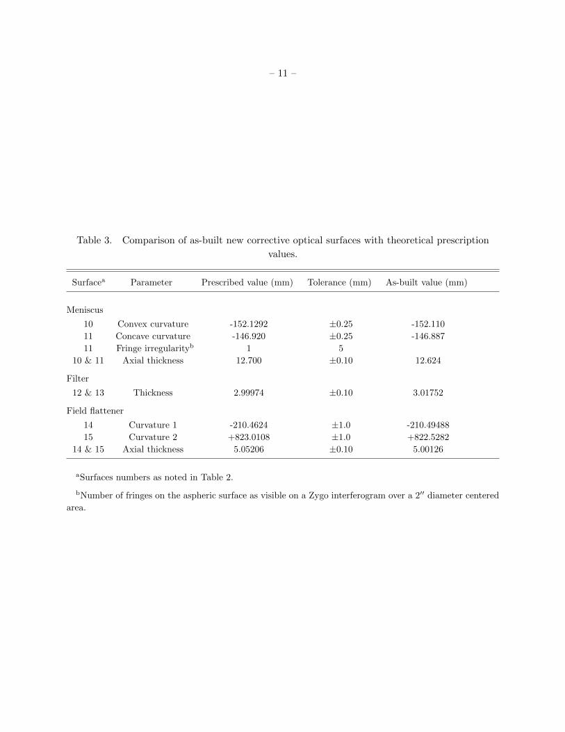
Table 3. Comparison of as-built new corrective optical surfaces with theoretical prescription
values.
Surfacea Parameter Prescribed value (mm) Tolerance (mm) As-built value (mm)
Meniscus
10 Convex curvature -152.1292 ±0.25 -152.110
11 Concave curvature -146.920 ±0.25 -146.887
11 Fringe irregularityb 1 5
10 & 11 Axial thickness 12.700 ±0.10 12.624
Filter
12 & 13 Thickness 2.99974 ±0.10 3.01752
Field flattener
14 Curvature 1 -210.4624 ±1.0 -210.49488
15 Curvature 2 +823.0108 ±1.0 +822.5282
14 & 15 Axial thickness 5.05206 ±0.10 5.00126
aSurfaces numbers as noted in Table 2.
bNumber of fringes on the aspheric surface as visible on a Zygo interferogram over a 2′′ diameter centered
area.

– 12 –
displayed stellar surfaces are the ones which the optic system project over the chip. Note the two
circular scratches can be seen on the upper right and lower left corners.
After repolishing and coating with MgF2, the 3-lens corrector was tested to have a 69% through-
put. The meniscus, field flattener, and filter are all coated with BBAR coatings with a reflectivity
of about 1% (on average) at each surface. So, the transmission for these three elements totals 94%.
The mirror was coated with Clausing’s Diamond BriteTM coating which has a stated reflectivity of
97%. So, in total, 63% of the incoming light reaches the chip.
2.2.4. Custom CCD camera
Our custom design CCD was based on the production prototype PL16803 from Finger Lakes
Instrumentation (FLI) Inc. (New York, USA), as can be seen in Fig. 11. Its main specifications
are: 4096x4096 9µm-pixel Kodak 16803 chip, 60% QE at 550nm, 9-11 e- readout noise, 1 MHz and
8 MHz readout speed at 16-bit digitization rate, the camera electronics and sensor chambers are
sealed with noble gas to keep the moisture out.
Aside from the above specifications, the CCD camera inside the TFRM tube had a number
of requirements specific to this project. For example, the field flattener lens and the filter must
be placed inside the camera body. In addition, conventional cooling by exhausting warm air from
inside the tube is not an option. Therefore, a recirculating liquid cooling system was implemented
by FLI, Inc. Finally, compactness of the CCD camera dimensions (6.2-inch×6.2-inch) was also
essential for fitting it into its spider housing. At the time of purchase, the PL16803 was found to
be the smallest large-format commercial CCD camera which met our requirements. A small size
was essential for our application to minimize the size of spider and CCD assembly, and therefore,
the obscuration over the image.
After taking stock and custom specifications into account, FLI, Inc. was found to be the
commercial manufacturer which best balances willingness of performing this custom design, quality
of product and reasonable cost.
Positioning the field flattener element within the camera body was one of the most critical
aspects of the project. The prescription of the refigured optics (see § 2.2.3) required the flattening
lens to sit 0.65 mm from the CCD sensor. Besides, the filter-sensor distance is such that the filter
had to be placed as the camera vacuum chamber window.
The procedure followed to assemble the corrective optics was supervised by one of us (MJM)
and performed by FLI. It was a complex sequence of precise measurements of the level of different
parts of the camera and optics to be assembled. From here, a few µm accurate positioning of the
flattener lens and filter with respect to the CCD sensor could be derived. The measurements were
taken with a standard micrometer depth gauge while working on a flat granite table.
One of the ’extreme’ characteristics of this optical system is the large angle (∼60◦) light cone

– 13 –
at focus. The result is a required shutter diameter that increases very quickly with distance from
the focal plane. Unfortunately for us, most commercial shutters are simply too small to allow
unobscured imaging with our camera system. And, the requirement become even more stringent if
the backfocal distance is to be kept within a reasonable range. As a result, a large aperture shutter
had to be considered. This device had to guarantee reliable performance as well as mechanical and
electrical stability, given the unattended nature of the TFRM. The CS90 model from Uniblitz Inc.
(New York, USA), with an aperture of 90 mm, was selected. FLI assembled the shutter internally
to the PL16803 camera body, which had to be modified to accommodate the larger diameter of
the shutter. As part of the shutter integration process, FLI provided for both auxiliary and USB
triggering of the shutter. Although the TFRM LAN latency could, in theory, provide a CCD image
timestamp precision of ±0.1 ms, the electrical and mechanical uncertainties of the CS90 shutter
decrease the precision to about 100 ms.
Although the CCD camera consumes a small amount of power (∼40 W), one should note that
it is stored inside two cavities: its housing in the spider assembly and the tube. If conventional air
cooling was employed, turbulence within the tube would result - possibly decreasing image quality.
As an alternative solution, our camera was designed to accommodate liquid cooling. At the time
of purchase, the FLI design was innovative in commercial cameras and has shown a performance
of typically +15◦ better cooling than the air option in the same camera. In addition, the use of
one cooling method does not preclude the other with this camera. The liquid cooling option can
accommodate a large amount of heat transfer from the camera to the outside environment. Should
the liquid cooling fail, air cooling can take its place. This, of course, would come at the expense of
image quality and cooling efficiency. As a coolant, we use a 25% solution of propylene glycol in dis-
tilled water. This is recirculated and maintained at a constant temperature by a ThermoCUBETM,
Solid State Cooling, Inc. chiller. The ThermoCUBETM can be remotely controlled and monitored
by the observatory control computer.
2.2.5. Reinforced glass-fiber enclosure
The TFRM and rest of observatory devices are installed in a new enclosure specially built for
this purpose. The enclosure has been designed, manufactured and assembled by GRPro Precision
Manufacturing, Inc. GRPro has extensive experience in astronomical enclosures, like the ones
machined for SuperWASP (North and South) projects which were source of inspiration for our
design (Pollacco 2007).
The TFRM 12 m x 5 m x 4.5 m reinforced glass-fiber enclosure is modular and allows a portable
installation. It has turned out to be robust in all kinds of adverse weather conditions with no
mechanical failures. As seen in Fig. 12, the facility has a sliding roof which, when opened, it leaves
the TFRM uncovered and ready to observe. The rest of the building is dedicated to the control
room. The South wall can be folded down by 90◦, so that the TFRM can observe up to 13◦
elevations.

– 14 –
The roof and South wall are moved by means of an hydraulic pump which activates a mechan-
ical chain, in the case of the former, and an hydraulic arm in the case of the latter. In case of a
power failure, backup 24 Vdc batteries allow the system to close the enclosure. Start and end points
of motions are monitored by means of mechanical limit switches which stop the motor supply.
A Vaisala MAWS100 meteorological station was installed at the communication tower of
OAdM. This station is composed by a WXT520 multisensor and two DRD11A precipitation sen-
sors. This guarantees continuous monitoring of enviromental conditions from the control software
via TCP/IP protocol.
In order to introduce redundancy in meteorological recordings and gain safety in the overall
TFRM operation, an independent set of sensors (two DRD11A for precipitation, one for humidity,
and one for daylight) were connected to a watchdog system located at the enclosure.
In contrast to control software which is running on a computer arquitecture, the watchdog
system is a stand-alone electronic device which runs off of backup battery power. In the case of a
crash of the control computer software, the watchdog will secure the facility by closing the enclosure
roof and ram when sunrise or a weather alert occur.
2.2.6. Observatory control and scheduling software
A state-of-the-art observatory control software based on a client-server architecture via a
Instrument-Neutral Distributed Interface (INDI) device communication protocol was created and
developed by one of us (ECD) (Downey 2011), who contributed to this refurbishment project as
a consultant. All the devices in the TFRM observatory communicate with their client and servers
via INDI protocol, which is designed to control a distributed network of devices in either remote
or robotic fashion. All communication uses TCP/IP sockets for reliable distributed operation.
Among other interesting features of INDI, we highlight the ability of clients to learn the
properties of a particular device at runtime using introspection. As a result, implementation of
clients and devices are decoupled which is crucial for code maintainance of both sides of a control
software. Also, the protocol is XML-based for passing parameters back and forth in a compact
efficient format. Typical bandwidth requirements for monitoring and control of all observatory
functions (except camera images) are on the order of a few tens of kbps, so even simple voice-grade
modem connections are sufficient for routine remote operation.
Whenever INDI detects any of several conditions considered dangerous for further observations
to continue it issues a weather alert. This includes excessive wind speed, humidity, detection of
rain, hail and snow, high levels of electrostatic atmospheric activity, and low UPS battery power.
When an alert is issued the system automatically closes the enclosure roof and ram. The INDI
configuration contains a parameter that allows adjusting the length of time an alert will remain in
effect after any or all causal factors have returned to normal.

– 15 –
INDI drivers were developed for all devices at the observatory which need active command or
record. Drivers are written in ANSI C for the Linux operating system. Within each driver is the
code that implements the desired functionality for one, and only one, INDI device. Some drivers
only provide services, such as target prediction. Other drivers control hardware. Drivers may also
communicate with other drivers. The INDI architecture places no restrictions on what a driver can
do. The only requirement is that it responds to INDI messages that arrive on its stdin stream for
its device and that it generates valid INDI messages from its device on its stdout stream.
Clients, like drivers, may do anything they wish so long as they communicate valid INDI
messages over the socket with which they connect to an indiserver. Otherwise clients can be
GUIs, command line programs, daemons or other process roles and may be written in any desired
language. Java language was chosen for the development of INDI GUIs clients, so that maximum
portability and consistency across platforms (Linux under KDE o Gnome, Windows and Mac OS)
was assured.
A short description of INDI clients follows:
1. I-INDI (stands for Interactive-INDI) provides remote command and monitoring capability
for all observatory systems except the CCD camera. See in Fig. 13 snapshots of some of the
I-INDI windows for the global status of most important devices, and control of environmental
variables, telescope pointing and pointing model.
2. S-INDI (stands for Sheduled-INDI) allows to dispatch robotic operations, whose observing
blocks were previously written in XML format. Using S-INDI you define the INDI commands
you want to execute, define the target and any additional constraints for the observation, then
the S-INDI device driver will decide the best time to perform the request. Many requests
may be pending simultaneously and the S-INDI driver will always attempt to perform each
of them at the best possible time.
3. CCD-INDI commands the CCD camera in a remote fashion. It can also read and write FITS
files from and to disk. It is intended only as a basic camera control and image display tool.
It is not intended to compete with very elaborate control and processing tools.
4. ANSI C language was chosen for the development of simple command line clients. These were
conceived for the purpose of implementing complex environmental conditions decisions via
high-level scriptable languages (Perl, Python or bash) that can be scheduled on the crontab
of the observatory control computer.
2.3. Observing site
The TFRM was installed at the Observatori Astronomic del Montsec (OAdM), in the Catalo-
nian Pre-Pyrenees, whose WGS84 coordinates are: φ = 42.◦0516 N, λ = 0.◦7293 E, and h = 1570 m

– 16 –
HMSL. To date, the OAdM is pioneered by the Consorci del Montsec, an institution run by the
Catalonian Government. The observatory is located at the Montsec d’Ares mountain, 50 km South
of the central Pyrenees, in the province of Lleida (Spain). The site was chosen after a site-testing
campaign. The OAdM also hosts the 0.8 m Joan Oro Telescope, named in honour of this famous
Catalonian researcher.
The installation of the TFRM at OAdM resulted in a number of infrastructure upgrades to
the facility as a whole: stable power line, a 100 Mbps Internet access via fiber optics cable, and
enhanced security fence.
2.4. Reproducibility of the refurbishment process
Including the TFRM, four BNCs have already succesfully refurbished, and another one (ARIES
in India) is in process.
This demonstrates that the combination of the current synergies between information tech-
nologies, devices control electronics, and control software advances enable the upgrading of this
kind of telescopes into a facility with unique specifications and great scientific potential. From
the originally manufactured 21 BNCs, there are still a good number that are inactive but in good
shape, which could benefit from a refurbishment project like ours.
Furthermore, in the case of TFRM, a number of steps of the refurbishment project were
accomplished by purchasing commercial components, which involve less cost and little posterior
engineering assembling work.
3. ONGOING SURVEYING PROGRAMS
3.1. Transiting exoplanets
The large FoV of the TFRM, together with its moderate aperture and robotic nature, allows
for the efficient detection of exoplanets by means of transit measurements with high signal-to-
noise ratio in the appropiate magnitude range. The suitability of such an instrument for exoplanet
research was confirmed earlier by the APT during their UNSW Extrasolar Planet Search during
the period of 2004-2007 (Christiansen et al. 2008). The subsequent catalogue that they produced
shows that refurbished BNCs can accomplish millimagnitude photometry at least up to V∼14 mag.
In order to confirm the APT performance, the TFRM observed a predicted transit of WASP-
37b, a known exoplanet, in a completely unsupervised robotic mode on 8 Apr 2011. The first
transit-like signatures of WASP-37b were detected by SuperWASP-N survey (La Palma) between
March and June in 2008 and 2009, and by SuperWASP-S survey (South Africa) during 2008 June to
July and 2009 March to July. The transit lightcurve spanned about 4.5 hours (see Fig. 14). Transit

– 17 –
analysis was carried out by Holger Voss using the reduction software described in Voss (2006). The
photometric performance shown by the TFRM was outstanding: differential photometric precision
of 4.3 mmag for WASP-37b (V∼12.7 mag), and 3 mmag for stars of similar magnitude. Aside from
the excellent precision, what is most relevant is that, if WASP-37b were unknown, TFRM would
have detected it as an exoplanet candidate on the very first night of observation, i.e., like a real-time
detection without the need of further phase-folded data points of posterior nights.
Other known exoplanets transits were observed by TFRM, all of them in the 12 mag<V<14.5 mag
range, with similar photometric precisions in all cases.
Irwin et al. (2009) proposed an interesting alternative observational approach which has been
executed by the MEarth project. In order to maximize the probability of detection of rocky super-
Earths in the Habitable Zone (HZ), MEarth is photometrically monitoring a sample of ∼2000
M-type stars, which have been pre-selected. MEarth operates 8 telescopes f/9 Ritchey-Chretien
with a field of view of 25′x25′ each. Due to this limited FoV (0.17 square degrees), this project
can only monitor a single star per telescope at a time. Despite this limitation on the efficiency
of the survey, only in 3-4 years of full operation, it has been able to detect the first super-Earth
(GJ1214b) with this new pre-selected strategy survey (Charbonneau et al. 2009).
As mentioned in Fors et al. (2010a), the 19.4 square degrees TFRM FoV is the most remarkable
feature of this telescope. This, combined with the fact that a 30-second exposure typically contains
∼20.000 stars with SNR>5 (V<15.5 mag) and a photometric precision better than 10 mmag (3-
4 mmag typically for V down to 13-13.5 mag), means that the telescope has a significant probability
in detecting new exoplanets by transit technique.
Since December 2011, and in collaboration with the team of Dr. Ignasi Ribas (ICE-CSIC), the
TFRM began to survey a pre-selected series of fields, with an input catalog similar to MEarth’s (Reid
et al. 1995; Hawley et al. 1996; Lepine & Gaidos 2011), in search of super-Earths around M-type
stars. The survey was called TFRM-PSES (TFRM-Preselected Super-Earths Survey). TFRM-
PSES monitors a number of M0 to M5-type catalogued targets comprised in several fields with
sufficient frequency each night, and in the range of 9.0 mag<V<15.5 mag. M targets per field dis-
tribution spans from 6 to 16, with a global median value of 8. However, up to 23 out of more
60 fields contain more than 13 M targets: typically 14 and 15, and 16 in one case. Note this is
the main difference between MEarth and TFRM-PSES: on one hand, while in MEarth each single
telescope monitors one star per CCD field, TFRM-PSES captures approximately 8 times as many
stars per field which, therefore, increases survey efficiency. On the other hand, the higher number
of telescopes in MEarth compensates the former said. Finally, that TFRM-PSES magnitude limit
of V=15.5 mag could be increased, but then the frequency of measurements would be less, which
would penalize efficiency when recording possible transits.
In particular, as seen in Fig. 15 the coverage of the TFRM-PSES survey to 5 Apr 2013 was
such that 48 of the 60 catalogued fields were observed at least once. The median number of epochs
is 12, and the total number of covered fields per night including repetitions is 635.

– 18 –
Preliminary results with respect to the photometric precision and exoplanets detection prob-
ability of TFRM-PSES survey were presented in Fors et al. (2012). This study showed that pho-
tometric precision down to 5 mmag is achieved in the range of 11.0 mag<V<14.0 mag. A more
in-depth study of the TFRM-PSES performance and subsequent detections is in process of publi-
cation.
A by-product result of TFRM-PSES survey is the detection of new variables stars. Although we
cannot provide detailed statistics of detection, a good example is the WASP-37b transit observation
formerly presented: in 4.5 hours of photometric measurements of all the objects in the 4.◦4×4.◦4
FoV, ten new variable stars of different types and magnitudes were detected.
3.2. Space debris
Among other TFRM capabilities, its 4.◦4×4.◦4 FoV, the telescope tracking at arbitrary α and
δ rates, and the CCD shutter commanding at will during the exposure are extremely useful for
the participation in Space Situational Awareness / Space Surveillance and Tracking (SSA/SST)
observational programs.
The TFRM’s large FoV is suitable to survey the entire visible geostationary belt from its
location. In fact, with TFRM we can cover twice our entire visible geostationary belt in a 12 hours
night. The best method to track and detect objects close to the geostationary orbit (GEO) is with
the telescope stopped, i.e. in a Earth-fixed Reference System. So the background stars will appear
as trails with length proportional to the exposure time and the objects in the GEO belt will appear
as quasi-point-like sources. A good example of the TFRM’s detection capability in a single image
is the Fig. 16, where in half FoV there are easily identifiable 8 GEO objects (two inside the same
circle forming a constellation) among the trailed background stars.
Furthermore, the telescope’s capability of tracking at arbitrary α and δ rates jointly with the
software control, permits the tracking of objects in any kind of orbit even Low Earth Orbits (LEO),
by simply entering its Two Line Elements (TLEs) in the INDI target property.
Commanding the CCD shutter at will during the exposure could be very useful for surveying
the sky looking for objects in any kind of orbit. This observing approach allows to cut the object
trails while the sidereal tracked exposures are timestamped. Nevertheless, this method has not
been tested yet.
The TFRM’s collaboration in the SSA/SST international effort develops in two different
projects: the European Space Agency (ESA) program and the International Scientific Optical
Network (ISON) survey.
TFRM is one of the Spanish assets that is involved in the ESA SSA/SST Preparatory Pro-
gramme (2009-2012). Telescopes and radars from other European countries also participate in this
project.

– 19 –
During 2011 TFRM took part in the third ESA CO-VI 7-day observational campaign. This was
an experimental satellite tracking campaign using European facilities, aimed to determine how accu-
rately existing telescopes can work together to track objects in geosynchronous orbits. The satellite
positions of every asset were submitted to the coordinating office at European Awareness Research
Laboratory for Space (Early-Space), which reported the global results of the campaign (Fruh et al.
2011). Systematic observations of different GEO satellites were conducted by TFRM to determine
1137 satellite angular positions, and partial TFRM results were presented (Montojo et al. 2011).
We estimate our astrometric precision in the GEO satellites angular coordinates to be below 0.′′5
in both coordinates.
In order to test our data quality, orbit determination from the angular measurements was
carried out using the Orbit Determination Tool Kit (ODTK) software package, from Analytical
Graphics, Inc. (AGI). As an example, in Fig. 17, we show 2-sigma (95%) uncertainties obtained
over the MSG2 satellite, with 175 angular measurements along 4 nights in which the satellite was
not maneuvered. The mean uncertainties in the classical elements, i.e., semiaxis, eccentricity and
inclination, are of the order of 12 m, 1.8·10−6 and 1.◦5·10−4, respectively. It is worth mentioning that
during this campaign the TFRM was still in commissioning period and the GEO objects reduction
process was performed using a non-automated and non-optimized software based on SExtractor.
Nowadays we can take advantage of the advanced and fully automated reduction software APEX-II
developed by Vladimir Kouprianov (Pulkovo Observatory).
At the time of writing the TFRM is about to participate in the imminent upcoming ESA
campaing “CO-VI Optical Observations for Space Surveillance and Tracking Test and Validations”.
The International Scientific Optical Network (ISON) is a civilian non-governmental project
devoted to space debris research and space situation awareness. TFRM is collaborating with ISON
in its sistematic survey of the GEO Protected Zone since 2011 (Agapov et al. 2011). Positional
measurements are derived using advanced trailed image reduction techniques included in APEX-
II sofware (Devyatkin et al. 2010). As a result of this collaboration, the TFRM is one of the
sensors that contributes to the completeness of the objects without Two-Line-Element data of ESA’s
DISCOS database, as stated at the last “Classification of Geosynchronous Objects Report” issued
by ESA (Floher 2012).
Currently TFRM is observing routinely and can detect an average of 400 GEO objects tracks
per night with an accuracy better than 0.′′5 in both coordinates and a limit magnitude of 16 mag.
Furthermore, the TFRM team is in the process of improving the limit of detection towards fainter
GEO objects (Fors et al. 2010c). Typically in a 12 hour night the TFRM is measuring around 2800
positions of 320 different objects.
A good example of the TFRM’s capabilities in the SST field was the early detection after
the MSG-3 (Meteosat 10) satellite launch. This GEO satellite was on its way after lifting off on
an Ariane 5 at 21:36 UTC on Thursday, 5 July from Europe’s Spaceport at the Guiana Space
Centre in Kourou, French Guiana. The MSG-3 was first detected by TFRM on the night of 12

– 20 –
July, during our routine collaboration in the ISON geosynchronous space survey. Three tracks (see
Fig. 18) were detected over the night with the automatic GEO objects detection software APEX-
II. With additional follow-up observations from other telescopes of ISON network, an initial orbit
determination was performed by ISON before the satellite TLEs were published, and the results
showed that the satellite was indeed the MSG-3, which was drifting East at 3◦ per hour rate. Hence,
it was caught maneuvering to its final 0◦ longitude expected geostationary slot.
3.3. Other observational programs
A number of other observational programs can benefit from TFRM specifications.
One is the collaboration in the Space Situational Awareness/NEO-segment (SSA/NEO). The
TFRM will also be one of the assets involved in the ESA SSA/NEOs segment. NEOs are small
solar system bodies whose orbits bring them close to Earth and which represent a potential threat
to the Earth. The NEO segment of the European SSA System will perform observations of NEOs,
predict their orbital evolution and impact risk, store observational and calculated data, issue NEO
information, news releases and impact warnings and support NEO mitigation measures. Concerning
NEO observations, ESA is planning to scan every night the complete visible sky with the aim to
detect objects which are only visible when they are close to Earth.
In the same context of SSA/NEO, the TFRM has the capability to contribute significantly
to the international effort of surveying and monitoring the population of NEOs: the observations
of NEOs by TFRM includes imaging asteroids at low solar elongation (an area usually poorly
searched) in collaboration with the NESS project, led by Dr. Alan R. Hildebrand (University of
Calgary) that will use the NEOSSat microsatellite to continuously search in this near-Sun region.
The similarities between the SSA/NEO and TFRM-PSES survey strategies make that one
program can partially benefit from other’s data. Furthermore, other survey programs related with
the search of Solar System objects, like main belt asteroids, comets, KBOs, and TNOs are also
partially compatible.
Another program which was initiated is the optical monitoring of γ-ray binaries. The final
aim is to study how the relativistic wind of the young non-acreating pulsar affects the circumstellar
envelope in γ-ray binaries through optical photometric variability. Preliminary observations in the
case of HD 215227 were presented in Paredes-Fortuny et al. (2012).
Finally, other alert programs, such as GRBs, SNs, novae, blazars, and other transients in
general can be allocated with the proper observational strategy.

– 21 –
4. DISCUSSION
A Baker-Nunn camera has been refurbished to operate with a large-format commercial CCD
camera in remote and robotic modes. A night view of the TFRM ready to observe is shown in
Fig. 19.
The refurbishment project included several steps, such as modification of the mount into a
motorized equatorial type, manufacture and installation of a new precise spider and focus system,
optics refiguring for flattening the CCD focal plane, customization of CCD camera, new rein-
forced glass-fiber enclosure with sliding roof and folding down South wall, and new observatory
control and scheduling software among others. Most of these steps were executed by the authors.
When required, specialiazed external personnel was hired (spider manufacture, CCD customiza-
tion, reinforced glass-fiber enclosure). The rest of work was carried out by purchasing commercial
components and assembling them with little engineering time.
The performance of the TFRM was shown by two different survey-type programs: millimag-
nitude precise photometry of exoplanets transits, and geostationary debris in the context of Space
Situational Awareness / Space Surveillance and Tracking (SSA/SST) programs.
All-in-all, the acquired know-how and the research return of the new refurbished facility fully
justifies the cost involved in the project, which is affordable even for small research institutions or
Universities.
Furthermore, a number of other BNCs are still inactive and stored in good conditions, ready to
be refurbished. With the usual decrease of cost when replicating a project, the TFRM refurbishment
project could be applied to such BNCs, and enable in a short term basis (1-2 years) each of these
telescopes in a scientific useful facility.
This effort was supported by the Ministerio de Ciencia e Innovacion of Spain (AyA2008-
01225 and others), and by Departament d’Universitats, Recerca i Societat de la Informacio of
the Catalonian Goverment (several grants). We acknowledge Alan R. Hildebrand and Robert
D. Cardinal for sharing their RAO BNC experience with us, which was highly beneficial for the
proper development of TFRM. This project has benefited from the wise advise of Ignasi Ribas,
Don Pollacco and Juan Carlos Morales, as well as from the data analysis expertise of Holger Voss
and Vladimir Kouprianov. Authors also acknowledge Daniel del Ser, and Albert Rosich and Estela
Martın-Badosa for their help in several figures generation with Python and ZEMAX, respectively.
Orbit Determination Tool Kit (ODTK) Analytical Graphics, Inc. (AGI) is a licensed software used
by ROA in collaboration with the Instituto Nacional de Tecnica Aeroespacial (INTA).
REFERENCES
Agapov V., Molotov I. & Kouprianov V. 2011, private communication

– 22 –
Baker, J.G. 1962, U.S. Patent 3,022,708
Carter, B. D., Ashley, M. C. B., Sun, Y.-S., & Storey, J. W. V. 1992, Proceedings of the Astro-
nomical Society of Australia, 10, 74
Charbonneau, D., Berta, Z. K., Irwin, J., et al. 2009, Nature, 462, 891
Christiansen, J. L., et al. 2008, MNRAS, 385, 1749
Devyatkin, A. V., Gorshanov, D. L., Kouprianov, V. V., & Verestchagina, I. A. 2010, Solar System
Research, 44, 68
Downey, E. C. 2011, Clear Sky Institute, Inc.: INDI Control System Architecture
Fors, O., et al. 2010a, Pathways Towards Habitable Planets, ASP Conference Series, 430, 428
Fors, O., et al. 2010b, Advanced Maui Optical and Space Surveillance Technologies Conference, 50
Fors, O., Nunez, J., Otazu, X., Prades, A., Cardinal, R. D. 2010c, Sensors, 10, 3, 1743
Fors, O., et al. 2011, Advanced Maui Optical and Space Surveillance Technologies Conference, 19
Fors, O., et al. 2012, CoolStars17, the 17th Cambridge Workshop on Cool Stars, Stellar Systems
and the Sun
Floher, T. 2012, Issue 14 Rev. 1 of Classification of Geosynchronous Objects, 17, 116
Fruh, C. et al. Proceedings of ESA European Space Surveillance Conference, WPP-321 (2011)
Gupta, K. G., Yadav, R. K. S., Bangia, T., Kumar, T. S., & Sharma, N. 2005, Bulletin of the
Astronomical Society of India, 33, 414
Hawley, S. L., Gizis, J. E., & Reid, I. N. 1996, AJ, 112, 2799
Henize, K. G. 1957, S&T, 16, 108
Mazur, M.J., Cardinal, R.D. & Hildebrand, A.R. 2005, Final Report for Baker Nunn Telescope
Retrofit, Defence Research and Development Canada, Ottawa, Contractor Report CR 2005-
040, 116 pp.
Irwin, J., Charbonneau, D., Nutzman, P., & Falco, E. 2009, IAU Symposium, 253, 37
Jeas, W. C., & Anctil, R. 1981, Military Electronics Countermeasures, 7, 47
Law, B., et al. 2002, Proc. SPIE, 4836, 119
Law, B., et al. 2006, Advanced Maui Optical and Space Surveillance Technologies Conference, 87
Lepine, S., & Gaidos, E. 2011, AJ, 142, 138

– 23 –
Montojo, F. J., et al. 2011, Proceedings of ESA European Space Surveillance Conference 2011
Paredes-Fortuny, X., Ribo, M., Fors, O., & Nunez, J. 2012, AIP Conference Proceedings, 1505, 390
Pollacco, D. 2007, private communication
Reid, I. N., Hawley, S. L., & Gizis, J. E. 1995, AJ, 110, 1838
Voss, H. 2006, PhD thesis, University of Berlin
This preprint was prepared with the AAS LATEX macros v5.2.
– 24 –
Fig. 1.— Baker-Nunn Camera at ROA in 1958.

– 25 –
Fig. 2.— Layout of original Baker-Nunn Camera design as defined in Table 1. Axial rays are
blocked by curved focal surface.
Fig. 3.— Mirror cell with six cylindrical counterweights and a ’floating’ mirror which is coupled
to the focal surface through 3 Invar rods. When the pointing or the temperature of the telescope
change, the BNC maintains focus throughout its large FoV.

– 26 –
Fig. 4.— Top: First 70 sec exposure technical image of M31 taken at TFRM on September 11,
2010. Note the huge FoV of the CCD (4.4◦x4.4◦). Bottom: Full resolution detail of spiral arm
area.
Fig. 5.— Foreground: TFRM at OAdM. Sliding roof half open and south gabling wall fully open.
Robotic refurbished BNC inside. Background: Joan Oro Telescope, also inside OAdM.

– 27 –
Fig. 6.— Left: 3D CAD layout of the design for the spider vanes and CCD focus system. In
the central cylindrical housing, from top to bottom, the focus motor, the CCD camera, its 90 mm
shutter, and the meniscus hold by eight red-coloured bolts are shown. At the right hand side of
the mid tube: tip-tilt adjuster is shown. Right: Finished midtube with spider vanes and CCD
housing.
Fig. 7.— Layout of the corrected Baker-Nunn Camera design coinceived for the TFRM as defined
in Table 2. Axial rays are blocked by spider central obstruction.

– 28 –
Fig. 8.— Outermost lens before (left) and after (right) repolishing.
Fig. 9.— Primary mirror before (left) and after (right) recoating.

– 29 –
2b
4d
4c
4b
4a
3a
3b
3c3d
2d2c2a
1b1a 1c
1d
Fig. 10.— A quantitative plot of achieved post-refurbishment point spread function (PSF) as a
function of field angle. Each encircled star on the top image is plotted in a 30×30pixels 3D surface.
From these, there does not appear to be significant image degradation with increasing field angle.

– 30 –
Fig. 11.— Finger Lakes Instrumentation Inc. (FLI) ProLine 16803 CCD with field flattener lens,
filter, and glycol recirculating cooling system. Uniblitz CS90 90 mm shutter and front of camera
cover were removed. Courtesy of FLI.
Fig. 12.— TFRM reinforced glass-fiber enclosure installed at OAdM, with sliding roof and South
gabling wall.

– 31 –
Fig. 13.— Four windows of I-INDI for TFRM remote control. Upper left: Main window which
summarizes the status of critical devices and circumstances. Upper right: Environmental vari-
ables, both instantaneous values and their plot versus time. Lower left: Manual telescope control.
Lower right: Pointing model with up to 13 coefficients and plot of reference stars and errors.

– 32 –
Fig. 14.— WASP-37b transit lightcurve observed by TFRM on Apr 8th 2011. Note that the left
and right baseline is not completely spanned because that corresponds to a single-night observation.
Photometric precision is 4.3 mmag.
Fig. 15.— Left: Catalogued fields with M dwarfs to be observed. Right: Fields with M dwarfs
already observed.

– 33 –
Fig. 16.— A 10s exposure taken with the TFRM where 8 GEO objects (two inside the same green
circle forming a constellation) and another object in a lower orbit are easily identifiable among the
trailed background stars. Only half of the TFRM FoV is shown. The orientation of the image is
North-leftwards and East-upwards.
Fig. 17.— Uncertainties in the position of the MSG2 satellite, at 2 sigmas (95%) and in RIC
coordinates. 2-Sigmas Intrack in red solid line. 2-Sigmas Radial in blue solid line. 2-Sigmas
Crosstrack in black dashed line. It is clearly noticeable the characteristic increasing of the Intrack
uncertainty during daytime.

– 34 –
Fig. 18.— Three tracks of MSG-3 satellite (point-like features) imaged by TFRM, while the satellite
orbit was maneuvering East at 3◦ per hour.
Fig. 19.— Night view of the TFRM observatory.