Embed Size (px)
Citation preview
1
RKC INSTRUMENT INC.
Temperature Controller Driver
1 System Configuration....................................................................................................... 3
2 Selection of External Device ............................................................................................ 8
3 Example of Communication Setting ................................................................................. 9
4 Setup Items .................................................................................................................... 87
5 Cable Diagram ............................................................................................................... 92
6 Supported Device......................................................................................................... 122
7 Device Code and Address Code.................................................................................. 177
8 Error Messages............................................................................................................ 182
Temperature Controller Driver
GP-Pro EX Device/PLC Connection Manual 2
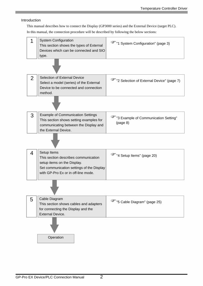
IntroductionThis manual describes how to connect the Display (GP3000 series) and the External Device (target PLC).
In this manual, the connection procedure will be described by following the below sections:
1 System ConfigurationThis section shows the types of External Devices which can be connected and SIO type.
"1 System Configuration" (page 3)
2 Selection of External DeviceSelect a model (series) of the External Device to be connected and connection method.
"2 Selection of External Device" (page 7)
3 Example of Communication SettingsThis section shows setting examples for communicating between the Display and the External Device.
"3 Example of Communication Setting" (page 8)
4 Setup ItemsThis section describes communication setup items on the Display.Set communication settings of the Display with GP-Pro Ex or in off-line mode.
"4 Setup Items" (page 20)
5 Cable DiagramThis section shows cables and adapters for connecting the Display and the External Device.
"5 Cable Diagram" (page 25)
Operation
Temperature Controller Driver
GP-Pro EX Device/PLC Connection Manual 3
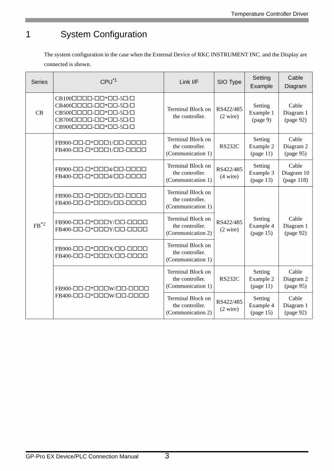
1 System Configuration
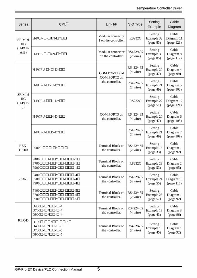
The system configuration in the case when the External Device of RKC INSTRUMENT INC. and the Display are
connected is shown.
Series CPU*1 Link I/F SIO TypeSetting
ExampleCable
Diagram
CB
CB100 - * -5 /CB400 - * -5 /CB500 - * -5 /CB700 - * -5 /CB900 - * -5 /
Terminal Block on the controller.
RS422/485(2 wire)
Setting Example 1 (page 9)
Cable Diagram 1 (page 92)
FB*2
FB900- - * 1/ -FB400- - * 1/ -
Terminal Block on the controller.
(Communication 1)RS232C
Setting Example 2 (page 11)
Cable Diagram 2 (page 95)
FB900- - * 4/ -FB400- - * 4/ -
Terminal Block on the controller.
(Communication 1)
RS422/485(4 wire)
Setting Example 3 (page 13)
Cable Diagram 10 (page 118)
FB900- - * 5/ -FB400- - * 5/ -
Terminal Block on the controller.
(Communication 1)
RS422/485(2 wire)
Setting Example 4 (page 15)
Cable Diagram 1 (page 92)
FB900- - * Y/ -FB400- - * Y/ -
Terminal Block on the controller.
(Communication 2)
FB900- - * X/ -FB400- - * X/ -
Terminal Block on the controller.
(Communication 1)
FB900- - * W/ -FB400- - * W/ -
Terminal Block on the controller.
(Communication 1)RS232C
Setting Example 2 (page 11)
Cable Diagram 2 (page 95)
Terminal Block on the controller.
(Communication 2)
RS422/485(2 wire)
Setting Example 4 (page 15)
Cable Diagram 1 (page 92)
Temperature Controller Driver
GP-Pro EX Device/PLC Connection Manual 4
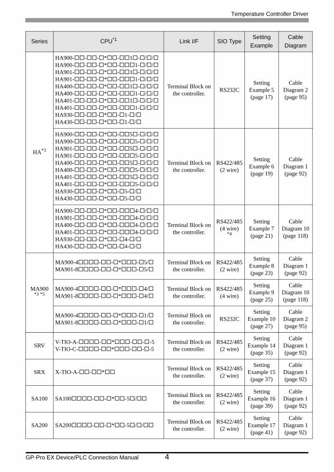
HA*3
HA900- - - * - 1 - / /HA900- - - * - 1- / /HA901- - - * - 1 - / /HA901- - - * - 1- / /HA400- - - * - 1 - / /HA400- - - * - 1- / /HA401- - - * - 1 - / /HA401- - - * - 1- / /HA930- - - * - 1- /HA430- - - * - 1- /
Terminal Block on the controller. RS232C
Setting Example 5 (page 17)
Cable Diagram 2 (page 95)
HA900- - - * - 5 - / /HA900- - - * - 5- / /HA901- - - * - 5 - / /HA901- - - * - 5- / /HA400- - - * - 5 - / /HA400- - - * - 5- / /HA401- - - * - 5 - / /HA401- - - * - 5- / /HA930- - - * - 5- /HA430- - - * - 5- /
Terminal Block on the controller.
RS422/485(2 wire)
Setting Example 6 (page 19)
Cable Diagram 1 (page 92)
HA900- - - * - 4- / /HA901- - - * - 4- / /HA400- - - * - 4- / /HA401- - - * - 4- / /HA930- - - * - 4- /HA430- - - * - 4- /
Terminal Block on the controller.
RS422/485(4 wire)
*4
Setting Example 7 (page 21)
Cable Diagram 10 (page 118)
MA900*3 *5
MA900-4 - - * - 5/MA901-8 - - * - 5/
Terminal Block on the controller.
RS422/485(2 wire)
Setting Example 8 (page 23)
Cable Diagram 1 (page 92)
MA900-4 - - * - 4/MA901-8 - - * - 4/
Terminal Block on the controller.
RS422/485(4 wire)
Setting Example 9 (page 25)
Cable Diagram 10 (page 118)
MA900-4 - - * - 1/MA901-8 - - * - 1/
Terminal Block on the controller. RS232C
Setting Example 10 (page 27)
Cable Diagram 2 (page 95)
SRV V-TIO-A- - * - - -5V-TIO-C- - * - - -5
Terminal Block on the controller.
RS422/485(2 wire)
Setting Example 14 (page 35)
Cable Diagram 1 (page 92)
SRX X-TIO-A- - * Terminal Block on the controller.
RS422/485(2 wire)
Setting Example 15 (page 37)
Cable Diagram 1 (page 92)
SA100 SA100 - - * -5 / Terminal Block on the controller.
RS422/485(2 wire)
Setting Example 16 (page 39)
Cable Diagram 1 (page 92)
SA200 SA200 - - * -5 / / Terminal Block on the controller.
RS422/485(2 wire)
Setting Example 17 (page 41)
Cable Diagram 1 (page 92)
Series CPU*1 Link I/F SIO TypeSetting
ExampleCable
Diagram
Temperature Controller Driver
GP-Pro EX Device/PLC Connection Manual 5
SR Mini HG
(H-PCP-A/B)
H-PCP- - 1N- * Modular connector 1 on the controller. RS232C
Setting Example 38 (page 83)
Cable Diagram 11 (page 121)
H-PCP- - 4N- * Modular connector on the controller.
RS422/485(2 wire)
Setting Example 39 (page 85)
Cable Diagram 8 (page 112)
SR Mini HG
(H-PCP-J)
H-PCP-J- 4 -D*COM.PORT1 and COM.PORT2 on
the controller.
RS422/485(4 wire)
Setting Example 20 (page 47)
Cable Diagram 4 (page 99)
H-PCP-J- 5 -D* RS422/485(2 wire)
Setting Example 21 (page 49)
Cable Diagram 5 (page 102)
H-PCP-J- 1-D*
COM.PORT3 on the controller.
RS232CSetting
Example 22 (page 51)
Cable Diagram 12 (page 121)
H-PCP-J- 4-D* RS422/485(4 wire)
Setting Example 20 (page 47)
Cable Diagram 6 (page 105)
H-PCP-J- 5-D* RS422/485(2 wire)
Setting Example 21 (page 49)
Cable Diagram 7 (page 109)
REX-F9000 F9000- - * / Terminal Block on
the controller.RS422/485
(2 wire)
Setting Example 13 (page 33)
Cable Diagram 1 (page 92)
REX-F
F400 - * - -1F700 - * - -1F900 - * - -1
Terminal Block on the controller. RS232C
Setting Example 23 (page 53)
Cable Diagram 2 (page 95)
F400 - * - -4F700 - * - -4F900 - * - -4
Terminal Block on the controller.
RS422/485(4 wire)
Setting Example 24 (page 55)
Cable Diagram 10 (page 118)
F400 - * - -5F700 - * - -5F900 - * - -5
Terminal Block on the controller.
RS422/485(2 wire)
Setting Example 25 (page 57)
Cable Diagram 1 (page 92)
REX-D
D400 - * - -4D700 - * - -4D900 - * - -4
Terminal Block on the controller.
RS422/485(4 wire)
Setting Example 18 (page 43)
Cable Diagram 3 (page 96)
D100 - * - -5D400 - * - -5D700 - * - -5D900 - * - -5
Terminal Block on the controller.
RS422/485(2 wire)
Setting Example 19 (page 45)
Cable Diagram 1 (page 92)
Series CPU*1 Link I/F SIO TypeSetting
ExampleCable
Diagram
Temperature Controller Driver
GP-Pro EX Device/PLC Connection Manual 6
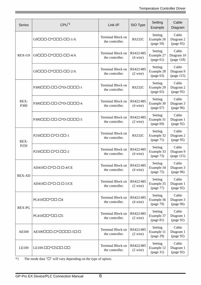
REX-G9
G9 - * - -1/A Terminal Block on the controller. RS232C
Setting Example 26 (page 59)
Cable Diagram 2 (page 95)
G9 - * - -4/A Terminal Block on the controller.
RS422/485(4 wire)
Setting Example 27 (page 61)
Cable Diagram 10 (page 118)
G9 - * - -2/A Terminal Block on the controller.
RS422/485(2 wire)
Setting Example 28 (page 63)
Cable Diagram 9 (page 115)
REX-P300
P300 - - *D- -1 Terminal Block on the controller. RS232C
Setting Example 29 (page 65)
Cable Diagram 2 (page 95)
P300 - - *D- -4 Terminal Block on the controller.
RS422/485(4 wire)
Setting Example 30 (page 67)
Cable Diagram 3 (page 96)
P300 - - *D- -5 Terminal Block on the controller.
RS422/485(2 wire)
Setting Example 31 (page 69)
Cable Diagram 1 (page 92)
REX-P250
P250 - * - -1 Terminal Block on the controller. RS232C
Setting Example 32 (page 71)
Cable Diagram 2 (page 95)
P250 - * - -2 Terminal Block on the controller.
RS422/485(4 wire)
Setting Example 33 (page 73)
Cable Diagram 9 (page 115)
REX-AD
AD410 - * - - -4/CE Terminal Block on the controller.
RS422/485(4 wire)
Setting Example 34 (page 75)
Cable Diagram 3 (page 96)
AD410 - * - - -5/CE Terminal Block on the controller.
RS422/485(2 wire)
Setting Example 35 (page 77)
Cable Diagram 1 (page 92)
REX-PG
PG410 * - 4 Terminal Block on the controller.
RS422/485(4 wire)
Setting Example 36 (page 79)
Cable Diagram 3 (page 96)
PG410 * - 5 Terminal Block on the controller.
RS422/485(2 wire)
Setting Example 37 (page 81)
Cable Diagram 1 (page 92)
AE500 AE500 - * -5 / Terminal Block on the controller.
RS422/485(2 wire)
Setting Example 11 (page 29)
Cable Diagram 1 (page 92)
LE100 LE100- * 5 - Terminal Block on the controller.
RS422/485(2 wire)
Setting Example 12 (page 31)
Cable Diagram 1 (page 92)
*1 The mode data " " will vary depending on the type of option.
Series CPU*1 Link I/F SIO TypeSetting
ExampleCable
Diagram
Temperature Controller Driver
GP-Pro EX Device/PLC Connection Manual 7
*2 There are two communication port: Communication 1 and Communication 2. Communication 1 is used for host communication. Communication 2 is used for intercontroller communication, but can be also used for host communication. When Communication 2 is used for host communication, it is necessary to change the protocol of Communication 2 (RKC communication is set).
*3 No memory area number is specified, "Control area" is used as default.
*4 Only Communication 2 supports RS-422 connection.
*5 Only support Single mode, Multi-point mode hasn't been supported.
Temperature Controller Driver
GP-Pro EX Device/PLC Connection Manual 8
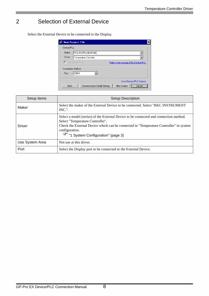
2 Selection of External Device
Select the External Device to be connected to the Display.
Setup Items Setup Description
Maker Select the maker of the External Device to be connected. Select "RKC INSTRUMENT INC.".
Driver
Select a model (series) of the External Device to be connected and connection method. Select "Temperature Controller".Check the External Device which can be connected in "Temperature Controller" in system configuration.
"1 System Configuration" (page 3)
Use System Area Not use at this driver.
Port Select the Display port to be connected to the External Device.
Temperature Controller Driver
GP-Pro EX Device/PLC Connection Manual 9
3 Example of Communication Setting
Examples of communication settings of the Display and the External Device, recommended by Pro-face, are
shown.
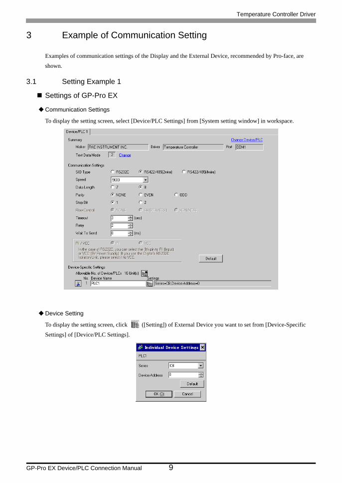
3.1 Setting Example 1
Settings of GP-Pro EX
Communication Settings
To display the setting screen, select [Device/PLC Settings] from [System setting window] in workspace.
Device Setting
To display the setting screen, click ([Setting]) of External Device you want to set from [Device-Specific
Settings] of [Device/PLC Settings].
Temperature Controller Driver
GP-Pro EX Device/PLC Connection Manual 10
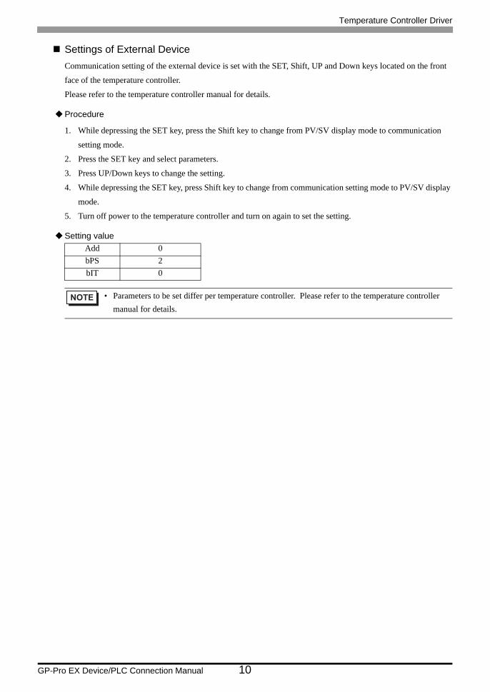
Settings of External DeviceCommunication setting of the external device is set with the SET, Shift, UP and Down keys located on the front
face of the temperature controller.
Please refer to the temperature controller manual for details.
Procedure
1. While depressing the SET key, press the Shift key to change from PV/SV display mode to communication
setting mode.
2. Press the SET key and select parameters.
3. Press UP/Down keys to change the setting.
4. While depressing the SET key, press Shift key to change from communication setting mode to PV/SV display
mode.
5. Turn off power to the temperature controller and turn on again to set the setting.
Setting valueAdd 0bPS 2bIT 0
• Parameters to be set differ per temperature controller. Please refer to the temperature controller manual for details.
Temperature Controller Driver
GP-Pro EX Device/PLC Connection Manual 11
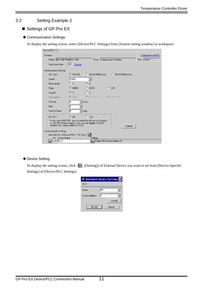
3.2 Setting Example 2
Settings of GP-Pro EX
Communication Settings
To display the setting screen, select [Device/PLC Settings] from [System setting window] in workspace.
Device Setting
To display the setting screen, click ([Setting]) of External Device you want to set from [Device-Specific
Settings] of [Device/PLC Settings].
Temperature Controller Driver
GP-Pro EX Device/PLC Connection Manual 12
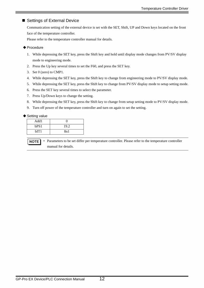
Settings of External DeviceCommunication setting of the external device is set with the SET, Shift, UP and Down keys located on the front
face of the temperature controller.
Please refer to the temperature controller manual for details.
Procedure
1. While depressing the SET key, press the Shift key and hold until display mode changes from PV/SV display
mode to engineering mode.
2. Press the Up key several times to set the F60, and press the SET key.
3. Set 0 (zero) to CMP1.
4. While depressing the SET key, press the Shift key to change from engineering mode to PV/SV display mode.
5. While depressing the SET key, press the Shift key to change from PV/SV display mode to setup setting mode.
6. Press the SET key several times to select the parameter.
7. Press Up/Down keys to change the setting.
8. While depressing the SET key, press the Shift key to change from setup setting mode to PV/SV display mode.
9. Turn off power of the temperature controller and turn on again to set the setting.
Setting valueAdd1 0bPS1 19.2bIT1 8n1
• Parameters to be set differ per temperature controller. Please refer to the temperature controller manual for details.
Temperature Controller Driver
GP-Pro EX Device/PLC Connection Manual 13
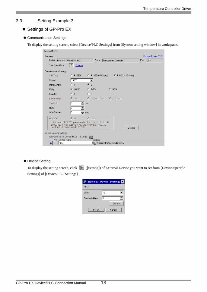
3.3 Setting Example 3
Settings of GP-Pro EX
Communication Settings
To display the setting screen, select [Device/PLC Settings] from [System setting window] in workspace.
Device Setting
To display the setting screen, click ([Setting]) of External Device you want to set from [Device-Specific
Settings] of [Device/PLC Settings].

Temperature Controller Driver
GP-Pro EX Device/PLC Connection Manual 14
Settings of External DeviceCommunication setting of the external device is set with the SET, Shift, UP and Down keys located on the front
face of the temperature controller.
Please refer to the temperature controller manual for details.
Procedure
1. While depressing the SET key, press the Shift key and hold until display mode changes from PV/SV display
mode to engineering mode.
2. Press the Up key several times to set the F60, and press the SET key.
3. Set 0 (zero) to CMP1.
4. While depressing the SET key, press the Shift key to change from engineering mode to PV/SV display mode.
5. While depressing the SET key, press the Shift key to change from PV/SV display mode to setup setting mode.
6. Press the SET key several times to select the parameter.
7. Press Up/Down keys to change the setting.
8. While depressing the SET key, press the Shift key to change from setup setting mode to PV/SV display mode.
9. Turn off power of the temperature controller and turn on again to set the setting.
Setting valueAdd1 0bPS1 19.2bIT1 8n1
• Parameters to be set differ per temperature controller. Please refer to the temperature controller manual for details.

Temperature Controller Driver
GP-Pro EX Device/PLC Connection Manual 15
3.4 Setting Example 4
Settings of GP-Pro EX
Communication Settings
To display the setting screen, select [Device/PLC Settings] from [System setting window] in workspace.
Device Setting
To display the setting screen, click ([Setting]) of External Device you want to set from [Device-Specific
Settings] of [Device/PLC Settings].

Temperature Controller Driver
GP-Pro EX Device/PLC Connection Manual 16
Settings of External DeviceCommunication setting of the external device is set with the SET, Shift, UP and Down keys located on the front
face of the temperature controller.
Please refer to the temperature controller manual for details.
Procedure
1. While depressing the SET key, press the Shift key and hold until display mode changes from PV/SV display
mode to engineering mode.
2. Press the Up key several times to set the F60, and press the SET key.
3. Set 0 (zero) to CMP1.
4. While depressing the SET key, press the Shift key to change from engineering mode to PV/SV display mode.
5. While depressing the SET key, press the Shift key to change from PV/SV display mode to setup setting mode.
6. Press the SET key several times to select the parameter.
7. Press Up/Down keys to change the setting.
8. While depressing the SET key, press the Shift key to change from setup setting mode to PV/SV display mode.
9. Turn off power of the temperature controller and turn on again to set the setting.
Setting valueAdd1 0bPS1 19.2bIT1 8n1
• Parameters to be set differ per temperature controller. Please refer to the temperature controller manual for details.

Temperature Controller Driver
GP-Pro EX Device/PLC Connection Manual 17
3.5 Setting Example 5
Settings of GP-Pro EX
Communication Settings
To display the setting screen, select [Device/PLC Settings] from [System setting window] in workspace.
Device Setting
To display the setting screen, click ([Setting]) of External Device you want to set from [Device-Specific
Settings] of [Device/PLC Settings].

Temperature Controller Driver
GP-Pro EX Device/PLC Connection Manual 18
Settings of External DeviceCommunication setting of the external device is set with the SET, Shift, UP and Down keys located on the front
face of the temperature controller.
Please refer to the temperature controller manual for details.
Procedure
1. While depressing the SET key, press the Shift key to change from SV setting & monitor mode to setup setting
mode.
2. Press the SET key and select parameters.
3. Press UP/Down keys to change the setting.
4. While depressing the SET key, press Shift key to change from setup setting mode to SV setting & monitor
mode.
5. Turn off power to the temperature controller and turn on again to set the setting.
Setting valueAdd1 0bPS1 9.6bIT1 8n1
• Parameters to be set differ per temperature controller. Please refer to the temperature controller manual for details.

Temperature Controller Driver
GP-Pro EX Device/PLC Connection Manual 19
3.6 Setting Example 6
Settings of GP-Pro EX
Communication Settings
To display the setting screen, select [Device/PLC Settings] from [System setting window] in workspace.
Device Setting
To display the setting screen, click ([Setting]) of External Device you want to set from [Device-Specific
Settings] of [Device/PLC Settings].

Temperature Controller Driver
GP-Pro EX Device/PLC Connection Manual 20
Settings of External DeviceCommunication setting of the external device is set with the SET, Shift, UP and Down keys located on the front
face of the temperature controller.
Please refer to the temperature controller manual for details.
Procedure
1. While depressing the SET key, press the Shift key to change from SV setting & monitor mode to setup setting
mode.
2. Press the SET key and select parameters.
3. Press UP/Down keys to change the setting.
4. While depressing the SET key, press Shift key to change from setup setting mode to SV setting & monitor
mode.
5. Turn off power to the temperature controller and turn on again to set the setting.
Setting valueAdd1 0bPS1 9.6bIT1 8n1
• Parameters to be set differ per temperature controller. Please refer to the temperature controller manual for details.

Temperature Controller Driver
GP-Pro EX Device/PLC Connection Manual 21
3.7 Setting Example 7
Settings of GP-Pro EX
Communication Settings
To display the setting screen, select [Device/PLC Settings] from [System setting window] in workspace.
Device Setting
To display the setting screen, click ([Setting]) of External Device you want to set from [Device-Specific
Settings] of [Device/PLC Settings].
Temperature Controller Driver
GP-Pro EX Device/PLC Connection Manual 22
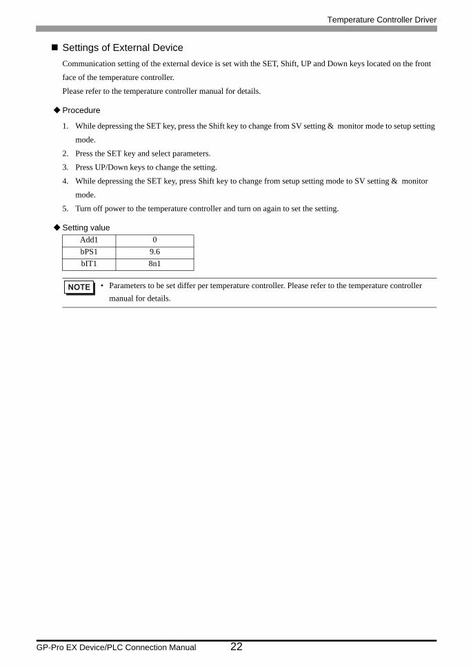
Settings of External DeviceCommunication setting of the external device is set with the SET, Shift, UP and Down keys located on the front
face of the temperature controller.
Please refer to the temperature controller manual for details.
Procedure
1. While depressing the SET key, press the Shift key to change from SV setting & monitor mode to setup setting
mode.
2. Press the SET key and select parameters.
3. Press UP/Down keys to change the setting.
4. While depressing the SET key, press Shift key to change from setup setting mode to SV setting & monitor
mode.
5. Turn off power to the temperature controller and turn on again to set the setting.
Setting valueAdd1 0bPS1 9.6bIT1 8n1
• Parameters to be set differ per temperature controller. Please refer to the temperature controller manual for details.

Temperature Controller Driver
GP-Pro EX Device/PLC Connection Manual 23
3.8 Setting Example 8
Settings of GP-Pro EX
Communication Settings
To display the setting screen, select [Device/PLC Settings] from [System setting window] in workspace.
Device Setting
To display the setting screen, click ([Setting]) of External Device you want to set from [Device-Specific
Settings] of [Device/PLC Settings].

Temperature Controller Driver
GP-Pro EX Device/PLC Connection Manual 24
Settings of External DeviceCommunication setting of the external device is set with the SET, Shift, UP and Down keys located on the front
face of the temperature controller.
Please refer to the temperature controller manual for details.
Procedure
1. While depressing the SET key, press the <R/S key to change from PV/SV display mode to setup setting mode.
2. Press the SET key and select parameters.
3. Press UP/Down keys and <R/S key to change the setting.
4. While depressing the SET key, press <R/S key to change from setup setting mode to PV/SV display mode.
5. Turn off power to the temperature controller and turn on again to set the setting.
Setting valueAdd 0bPS 960bIT 8n1
• Parameters to be set differ per temperature controller. Please refer to the temperature controller manual for details.

Temperature Controller Driver
GP-Pro EX Device/PLC Connection Manual 25
3.9 Setting Example 9
Settings of GP-Pro EX
Communication Settings
To display the setting screen, select [Device/PLC Settings] from [System setting window] in workspace.
Device Setting
To display the setting screen, click ([Setting]) of External Device you want to set from [Device-Specific
Settings] of [Device/PLC Settings].
Temperature Controller Driver
GP-Pro EX Device/PLC Connection Manual 26
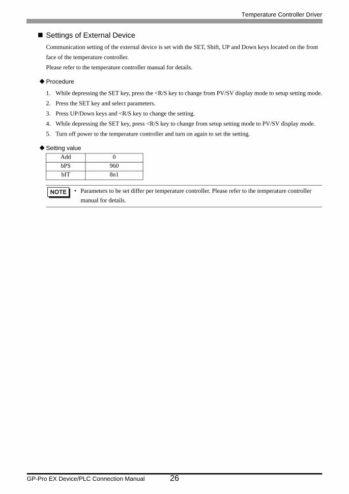
Settings of External DeviceCommunication setting of the external device is set with the SET, Shift, UP and Down keys located on the front
face of the temperature controller.
Please refer to the temperature controller manual for details.
Procedure
1. While depressing the SET key, press the <R/S key to change from PV/SV display mode to setup setting mode.
2. Press the SET key and select parameters.
3. Press UP/Down keys and <R/S key to change the setting.
4. While depressing the SET key, press <R/S key to change from setup setting mode to PV/SV display mode.
5. Turn off power to the temperature controller and turn on again to set the setting.
Setting valueAdd 0bPS 960bIT 8n1
• Parameters to be set differ per temperature controller. Please refer to the temperature controller manual for details.

Temperature Controller Driver
GP-Pro EX Device/PLC Connection Manual 27
3.10 Setting Example 10
Settings of GP-Pro EX
Communication Settings
To display the setting screen, select [Device/PLC Settings] from [System setting window] in workspace.
Device Setting
To display the setting screen, click ([Setting]) of External Device you want to set from [Device-Specific
Settings] of [Device/PLC Settings].

Temperature Controller Driver
GP-Pro EX Device/PLC Connection Manual 28
Settings of External DeviceCommunication setting of the external device is set with the SET, Shift, UP and Down keys located on the front
face of the temperature controller.
Please refer to the temperature controller manual for details.
Procedure
1. While depressing the SET key, press the <R/S key to change from PV/SV display mode to setup setting mode.
2. Press the SET key and select parameters.
3. Press UP/Down keys and <R/S key to change the setting.
4. While depressing the SET key, press <R/S key to change from setup setting mode to PV/SV display mode.
5. Turn off power to the temperature controller and turn on again to set the setting.
Setting valueAdd 0bPS 960bIT 8n1
• Parameters to be set differ per temperature controller. Please refer to the temperature controller manual for details.

Temperature Controller Driver
GP-Pro EX Device/PLC Connection Manual 29
3.11 Setting Example 11
Settings of GP-Pro EX
Communication Settings
To display the setting screen, select [Device/PLC Settings] from [System setting window] in workspace.
Device Setting
To display the setting screen, click ([Setting]) of External Device you want to set from [Device-Specific
Settings] of [Device/PLC Settings].
Temperature Controller Driver
GP-Pro EX Device/PLC Connection Manual 30
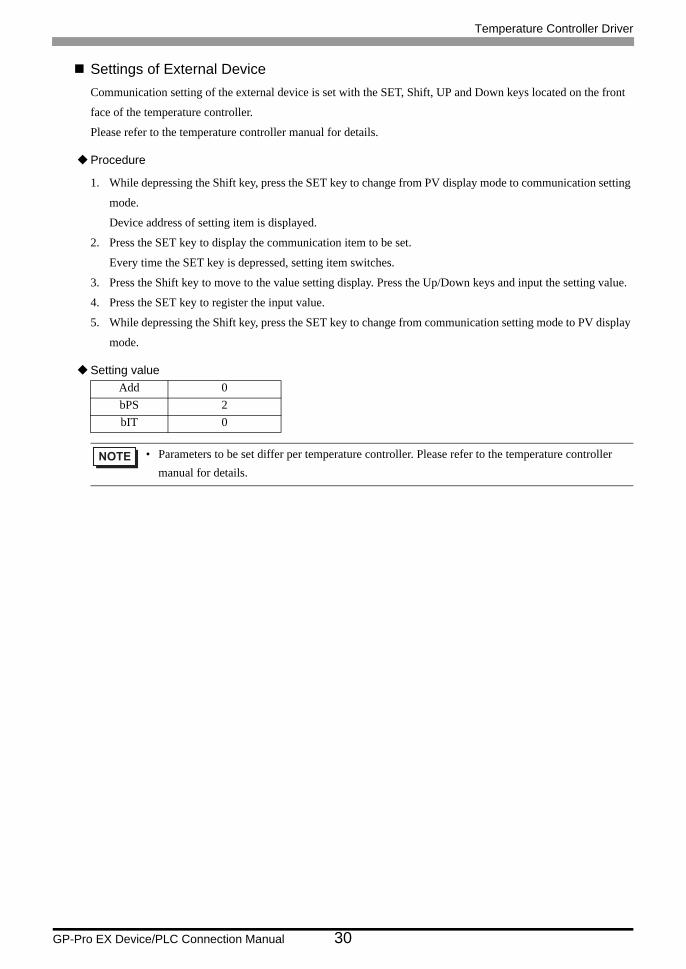
Settings of External DeviceCommunication setting of the external device is set with the SET, Shift, UP and Down keys located on the front
face of the temperature controller.
Please refer to the temperature controller manual for details.
Procedure
1. While depressing the Shift key, press the SET key to change from PV display mode to communication setting
mode.
Device address of setting item is displayed.
2. Press the SET key to display the communication item to be set.
Every time the SET key is depressed, setting item switches.
3. Press the Shift key to move to the value setting display. Press the Up/Down keys and input the setting value.
4. Press the SET key to register the input value.
5. While depressing the Shift key, press the SET key to change from communication setting mode to PV display
mode.
Setting valueAdd 0bPS 2bIT 0
• Parameters to be set differ per temperature controller. Please refer to the temperature controller manual for details.

Temperature Controller Driver
GP-Pro EX Device/PLC Connection Manual 31
3.12 Setting Example 12
Settings of GP-Pro EX
Communication Settings
To display the setting screen, select [Device/PLC Settings] from [System setting window] in workspace.
Device Setting
To display the setting screen, click ([Setting]) of External Device you want to set from [Device-Specific
Settings] of [Device/PLC Settings].
Temperature Controller Driver
GP-Pro EX Device/PLC Connection Manual 32
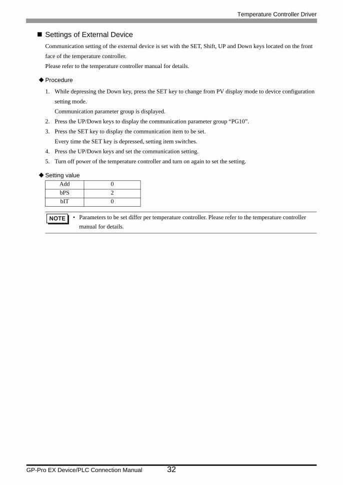
Settings of External DeviceCommunication setting of the external device is set with the SET, Shift, UP and Down keys located on the front
face of the temperature controller.
Please refer to the temperature controller manual for details.
Procedure
1. While depressing the Down key, press the SET key to change from PV display mode to device configuration
setting mode.
Communication parameter group is displayed.
2. Press the UP/Down keys to display the communication parameter group “PG10”.
3. Press the SET key to display the communication item to be set.
Every time the SET key is depressed, setting item switches.
4. Press the UP/Down keys and set the communication setting.
5. Turn off power of the temperature controller and turn on again to set the setting.
Setting valueAdd 0bPS 2bIT 0
• Parameters to be set differ per temperature controller. Please refer to the temperature controller manual for details.

Temperature Controller Driver
GP-Pro EX Device/PLC Connection Manual 33
3.13 Setting Example 13
Settings of GP-Pro EX
Communication Settings
To display the setting screen, select [Device/PLC Settings] from [System setting window] in workspace.
Device Setting
To display the setting screen, click ([Setting]) of External Device you want to set from [Device-Specific
Settings] of [Device/PLC Settings].
Temperature Controller Driver
GP-Pro EX Device/PLC Connection Manual 34
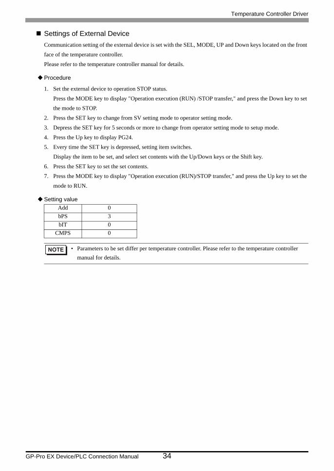
Settings of External DeviceCommunication setting of the external device is set with the SEL, MODE, UP and Down keys located on the front
face of the temperature controller.
Please refer to the temperature controller manual for details.
Procedure
1. Set the external device to operation STOP status.
Press the MODE key to display "Operation execution (RUN) /STOP transfer," and press the Down key to set
the mode to STOP.
2. Press the SET key to change from SV setting mode to operator setting mode.
3. Depress the SET key for 5 seconds or more to change from operator setting mode to setup mode.
4. Press the Up key to display PG24.
5. Every time the SET key is depressed, setting item switches.
Display the item to be set, and select set contents with the Up/Down keys or the Shift key.
6. Press the SET key to set the set contents.
7. Press the MODE key to display "Operation execution (RUN)/STOP transfer," and press the Up key to set the
mode to RUN.
Setting valueAdd 0bPS 3bIT 0
CMPS 0
• Parameters to be set differ per temperature controller. Please refer to the temperature controller manual for details.

Temperature Controller Driver
GP-Pro EX Device/PLC Connection Manual 35
3.14 Setting Example 14
Settings of GP-Pro EX
Communication Settings
To display the setting screen, select [Device/PLC Settings] from [System setting window] in workspace.
Device Setting
To display the setting screen, click ([Setting]) of External Device you want to set from [Device-Specific
Settings] of [Device/PLC Settings].

Temperature Controller Driver
GP-Pro EX Device/PLC Connection Manual 36
Settings of External DeviceCommunication setting of the external device is set with the rotary switch on the front face of the temperature
controller and the dip switch in the temperature controller.
Please refer to the temperature controller manual for details.
Procedure
1. Set module address with the rotary switch on the front face of the temperature controller.
2. Set communication speed and data bit construction with the dip switch on the side of the temperature
controller.
Setting value
Rotary switch
Dip switch
Upper Digit Setting 0Lower Digit Setting 0
Dip switch Setting DescriptionSW1 ON
Communication speedSW2 OFFSW3 ON
Data bit constructionSW4 OFFSW5 OFFSW6 OFF Protocol constructionSW7 OFF
FixedSW8 OFF

Temperature Controller Driver
GP-Pro EX Device/PLC Connection Manual 37
3.15 Setting Example 15
Settings of GP-Pro EX
Communication Settings
To display the setting screen, select [Device/PLC Settings] from [System setting window] in workspace.
Device Setting
To display the setting screen, click ([Setting]) of External Device you want to set from [Device-Specific
Settings] of [Device/PLC Settings].
Temperature Controller Driver
GP-Pro EX Device/PLC Connection Manual 38
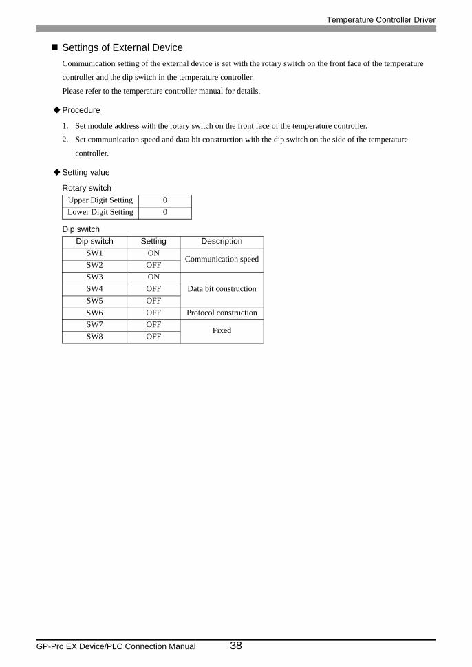
Settings of External DeviceCommunication setting of the external device is set with the rotary switch on the front face of the temperature
controller and the dip switch in the temperature controller.
Please refer to the temperature controller manual for details.
Procedure
1. Set module address with the rotary switch on the front face of the temperature controller.
2. Set communication speed and data bit construction with the dip switch on the side of the temperature
controller.
Setting value
Rotary switch
Dip switch
Upper Digit Setting 0Lower Digit Setting 0
Dip switch Setting DescriptionSW1 ON
Communication speedSW2 OFFSW3 ON
Data bit constructionSW4 OFFSW5 OFFSW6 OFF Protocol constructionSW7 OFF
FixedSW8 OFF

Temperature Controller Driver
GP-Pro EX Device/PLC Connection Manual 39
3.16 Setting Example 16
Settings of GP-Pro EX
Communication Settings
To display the setting screen, select [Device/PLC Settings] from [System setting window] in workspace.
Device Setting
To display the setting screen, click ([Setting]) of External Device you want to set from [Device-Specific
Settings] of [Device/PLC Settings].

Temperature Controller Driver
GP-Pro EX Device/PLC Connection Manual 40
Settings of External DeviceCommunication setting of the external device is set with the SET, Shift, UP and Down keys located on the front
face of the temperature controller.
Please refer to the temperature controller manual for details.
Procedure
1. While depressing the SET key, press the Shift key to change from PV/SV display mode to communication
setting mode.
2. Press the SET key and select parameters.
3. Press UP/Down keys to change the setting.
4. While depressing the SET key, press Shift key to change from communication setting mode to PV/SV display
mode.
5. Turn off power to the temperature controller and turn on again to set the setting.
Setting valueAdd 0bPS 960bIT 8n1
• Parameters to be set differ per temperature controller. Please refer to the temperature controller manual for details.
Temperature Controller Driver
GP-Pro EX Device/PLC Connection Manual 41
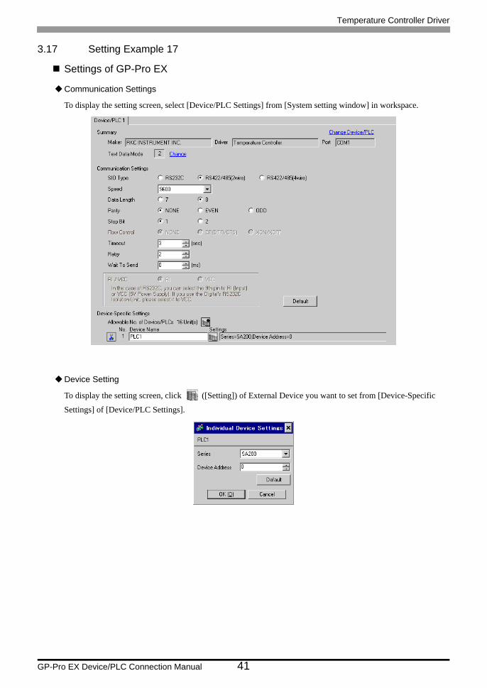
3.17 Setting Example 17
Settings of GP-Pro EX
Communication Settings
To display the setting screen, select [Device/PLC Settings] from [System setting window] in workspace.
Device Setting
To display the setting screen, click ([Setting]) of External Device you want to set from [Device-Specific
Settings] of [Device/PLC Settings].

Temperature Controller Driver
GP-Pro EX Device/PLC Connection Manual 42
Settings of External DeviceCommunication setting of the external device is set with the SET, Shift, UP and Down keys located on the front
face of the temperature controller.
Please refer to the temperature controller manual for details.
Procedure
1. While depressing the SET key, press the Shift key to change from PV/SV display mode to communication
setting mode.
2. Press the SET key and select parameters.
3. Press UP/Down keys to change the setting.
4. While depressing the SET key, press Shift key to change from communication setting mode to PV/SV display
mode.
5. Turn off power to the temperature controller and turn on again to set the setting.
Setting valueAdd 0bPS 960bIT 8n1
• Parameters to be set differ per temperature controller. Please refer to the temperature controller manual for details.

Temperature Controller Driver
GP-Pro EX Device/PLC Connection Manual 43
3.18 Setting Example 18
Settings of GP-Pro EX
Communication Settings
To display the setting screen, select [Device/PLC Settings] from [System setting window] in workspace.
Device Setting
To display the setting screen, click ([Setting]) of External Device you want to set from [Device-Specific
Settings] of [Device/PLC Settings].

Temperature Controller Driver
GP-Pro EX Device/PLC Connection Manual 44
Settings of External DeviceCommunication setting of the external device is set with the SEL, MONI/MODE, UP and Down keys located on
the front face of the temperature controller.
Please refer to the temperature controller manual for details.
Procedure
1. Depress the SEL key for 2 seconds to change from PV display mode to engineer setting mode.
Parameter group is displayed.
2. Press the Up/Down keys to display the parameter group, "PG8."
3. Press the SEL key to display the setting item. Every time the SEL key is depressed, setting item switches.
4. Press the Up/Down keys to select the setting value, and press the SEL key.
5. Press the Monitor/Mode key to switch to the PV display mode.
6. Press the Monitor/Mode key and the SEL key at the same time to change from PV display mode to SETUP
setting mode.
7. Press the SEL key several times to display Add.
8. Press the Up/Down keys to input set value, and press the SEL key to set the input value.
9. Press the Monitor/Mode keys to switch to the PV display mode.
10. Turn off power of external device off, and turn it on again.
Setting value
Engineer setting mode
SETUP setting mode
bPS 3bIT 0
Add 0
• Parameters to be set differ per temperature controller. Please refer to the temperature controller manual for details.

Temperature Controller Driver
GP-Pro EX Device/PLC Connection Manual 45
3.19 Setting Example 19
Settings of GP-Pro EX
Communication Settings
To display the setting screen, select [Device/PLC Settings] from [System setting window] in workspace.
Device Setting
To display the setting screen, click ([Setting]) of External Device you want to set from [Device-Specific
Settings] of [Device/PLC Settings].
Temperature Controller Driver
GP-Pro EX Device/PLC Connection Manual 46
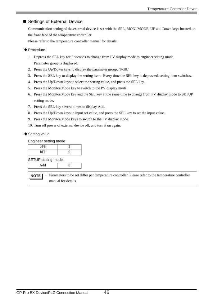
Settings of External DeviceCommunication setting of the external device is set with the SEL, MONI/MODE, UP and Down keys located on
the front face of the temperature controller.
Please refer to the temperature controller manual for details.
Procedure
1. Depress the SEL key for 2 seconds to change from PV display mode to engineer setting mode.
Parameter group is displayed.
2. Press the Up/Down keys to display the parameter group, "PG8."
3. Press the SEL key to display the setting item. Every time the SEL key is depressed, setting item switches.
4. Press the Up/Down keys to select the setting value, and press the SEL key.
5. Press the Monitor/Mode key to switch to the PV display mode.
6. Press the Monitor/Mode key and the SEL key at the same time to change from PV display mode to SETUP
setting mode.
7. Press the SEL key several times to display Add.
8. Press the Up/Down keys to input set value, and press the SEL key to set the input value.
9. Press the Monitor/Mode keys to switch to the PV display mode.
10. Turn off power of external device off, and turn it on again.
Setting value
Engineer setting mode
SETUP setting mode
bPS 3bIT 0
Add 0
• Parameters to be set differ per temperature controller. Please refer to the temperature controller manual for details.
Temperature Controller Driver
GP-Pro EX Device/PLC Connection Manual 47
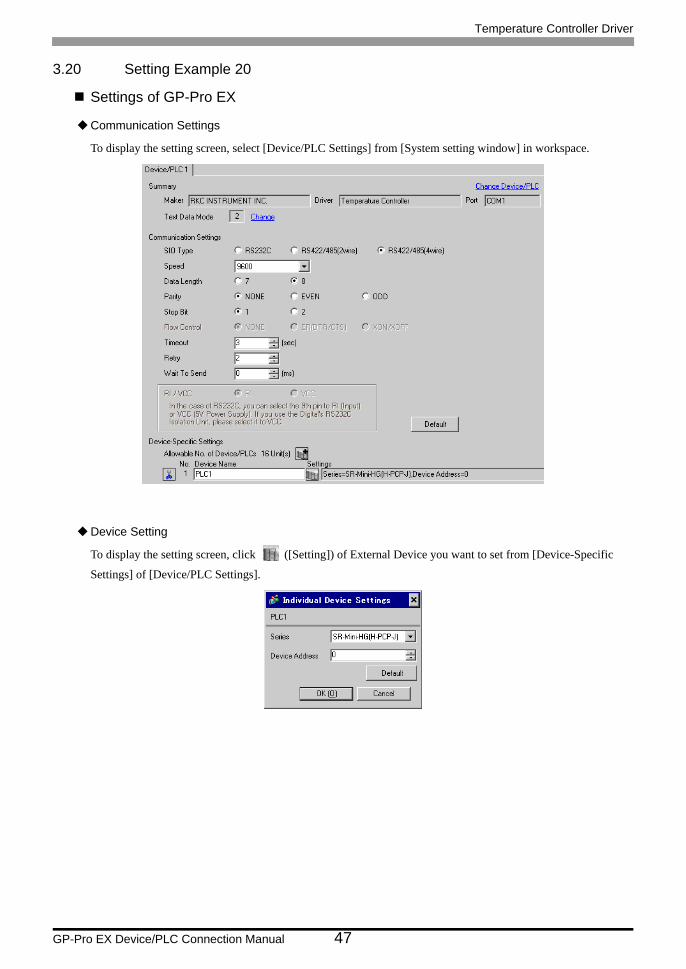
3.20 Setting Example 20
Settings of GP-Pro EX
Communication Settings
To display the setting screen, select [Device/PLC Settings] from [System setting window] in workspace.
Device Setting
To display the setting screen, click ([Setting]) of External Device you want to set from [Device-Specific
Settings] of [Device/PLC Settings].
Temperature Controller Driver
GP-Pro EX Device/PLC Connection Manual 48
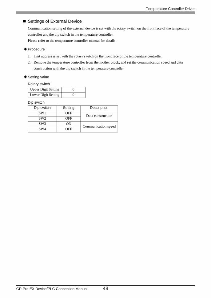
Settings of External DeviceCommunication setting of the external device is set with the rotary switch on the front face of the temperature
controller and the dip switch in the temperature controller.
Please refer to the temperature controller manual for details.
Procedure
1. Unit address is set with the rotary switch on the front face of the temperature controller.
2. Remove the temperature controller from the mother block, and set the communication speed and data
construction with the dip switch in the temperature controller.
Setting value
Rotary switch
Dip switch
Upper Digit Setting 0Lower Digit Setting 0
Dip switch Setting DescriptionSW1 OFF
Data constructionSW2 OFFSW3 ON
Communication speedSW4 OFF
Temperature Controller Driver
GP-Pro EX Device/PLC Connection Manual 49
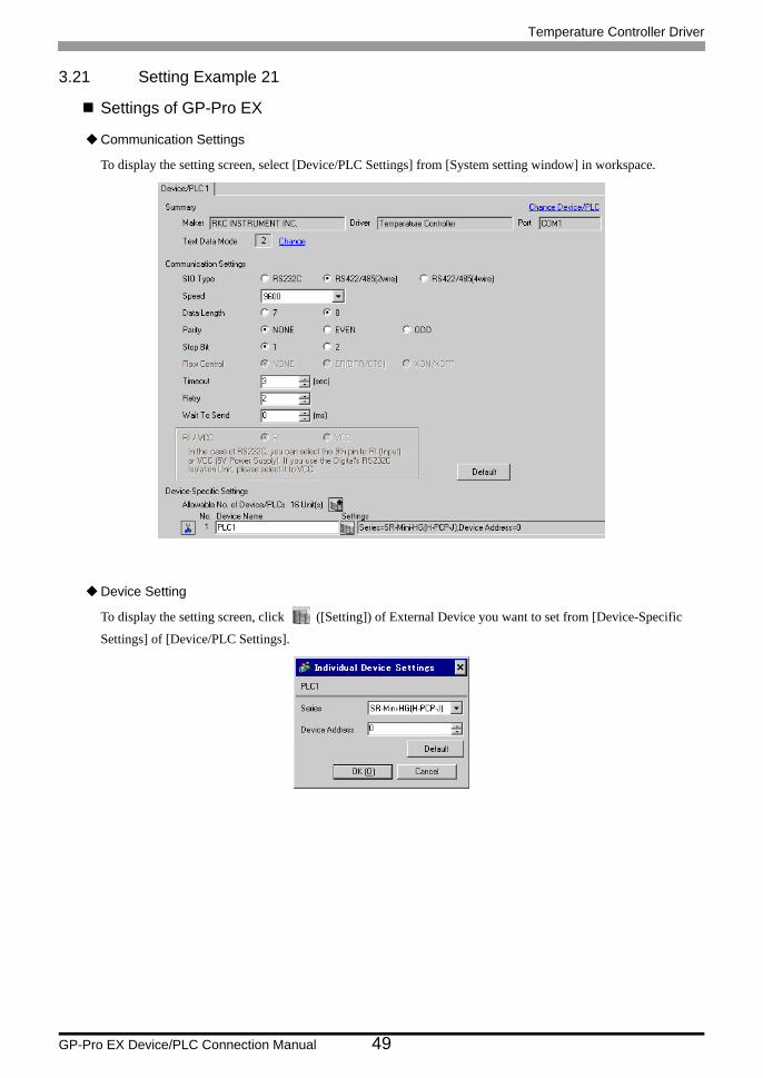
3.21 Setting Example 21
Settings of GP-Pro EX
Communication Settings
To display the setting screen, select [Device/PLC Settings] from [System setting window] in workspace.
Device Setting
To display the setting screen, click ([Setting]) of External Device you want to set from [Device-Specific
Settings] of [Device/PLC Settings].

Temperature Controller Driver
GP-Pro EX Device/PLC Connection Manual 50
Settings of External DeviceCommunication setting of the external device is set with the rotary switch on the front face of the temperature
controller and the dip switch in the temperature controller.
Please refer to the temperature controller manual for details.
Procedure
1. Unit address is set with the rotary switch on the front face of the temperature controller.
2. Remove the temperature controller from the mother block, and set the communication speed and data
construction with the dip switch in the temperature controller.
Setting value
Rotary switch
Dip switch
Upper Digit Setting 0Lower Digit Setting 0
Dip switch Setting DescriptionSW1 OFF
Data constructionSW2 OFFSW3 ON
Communication speedSW4 OFF

Temperature Controller Driver
GP-Pro EX Device/PLC Connection Manual 51
3.22 Setting Example 22
Settings of GP-Pro EX
Communication Settings
To display the setting screen, select [Device/PLC Settings] from [System setting window] in workspace.
Device Setting
To display the setting screen, click ([Setting]) of External Device you want to set from [Device-Specific
Settings] of [Device/PLC Settings].
Temperature Controller Driver
GP-Pro EX Device/PLC Connection Manual 52
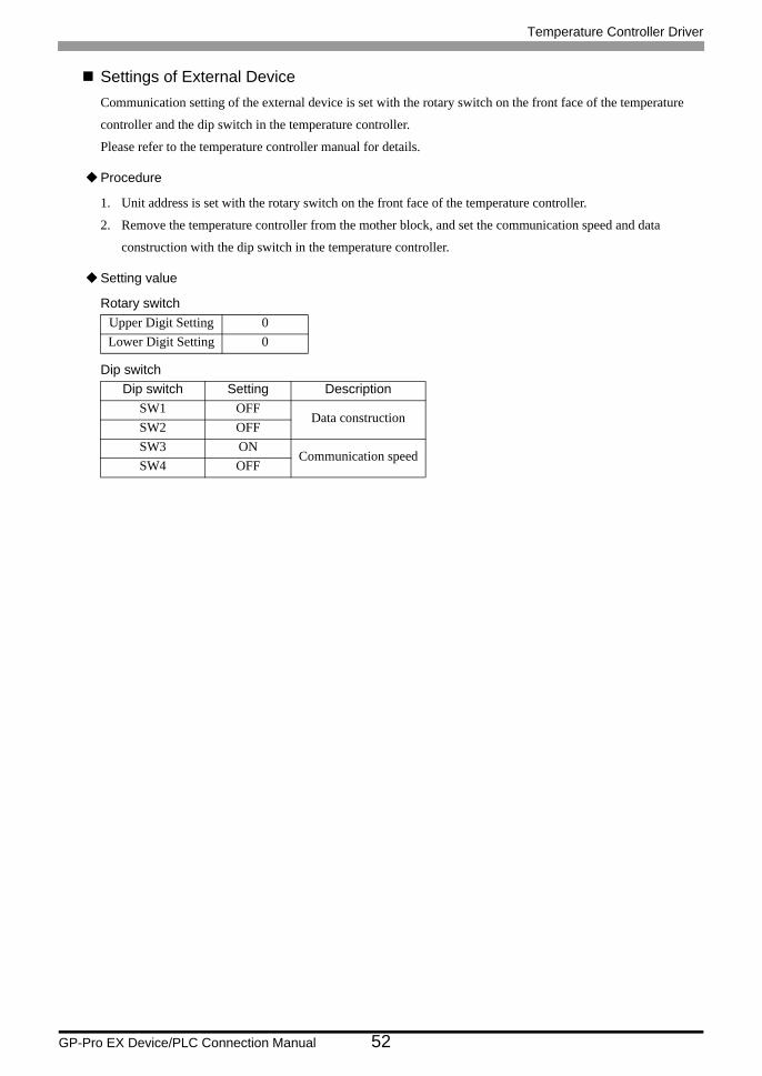
Settings of External DeviceCommunication setting of the external device is set with the rotary switch on the front face of the temperature
controller and the dip switch in the temperature controller.
Please refer to the temperature controller manual for details.
Procedure
1. Unit address is set with the rotary switch on the front face of the temperature controller.
2. Remove the temperature controller from the mother block, and set the communication speed and data
construction with the dip switch in the temperature controller.
Setting value
Rotary switch
Dip switch
Upper Digit Setting 0Lower Digit Setting 0
Dip switch Setting DescriptionSW1 OFF
Data constructionSW2 OFFSW3 ON
Communication speedSW4 OFF
Temperature Controller Driver
GP-Pro EX Device/PLC Connection Manual 53
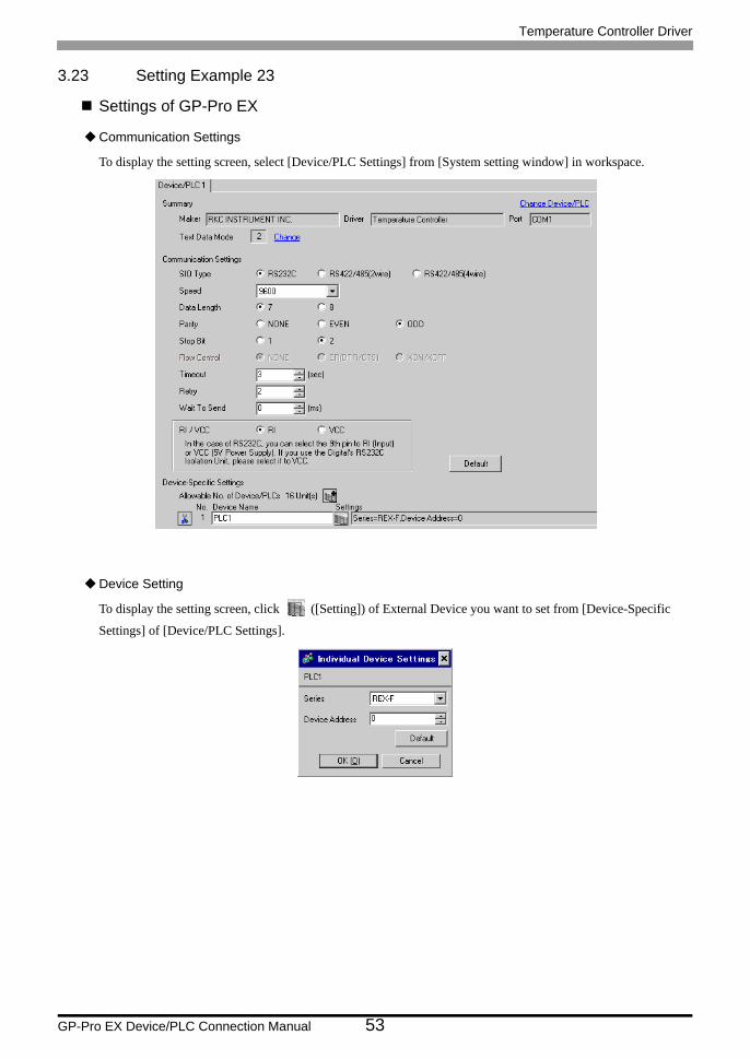
3.23 Setting Example 23
Settings of GP-Pro EX
Communication Settings
To display the setting screen, select [Device/PLC Settings] from [System setting window] in workspace.
Device Setting
To display the setting screen, click ([Setting]) of External Device you want to set from [Device-Specific
Settings] of [Device/PLC Settings].

Temperature Controller Driver
GP-Pro EX Device/PLC Connection Manual 54
Settings of External DeviceCommunication setting of the external device is set with the SEL, MODE, UP and Down keys located on the front
face of the temperature controller.
Please refer to the temperature controller manual for details.
Procedure
1. Set the external device to the operation STOP status.
Press the MODE key several times to display "Operation execution (RUN) /STOP transfer," and press the
Down key to set the mode to STOP.
2. Press the SET key to call up the set operator level 1.
3. Depress the SET key for 5 seconds or more to call up the set operator level 2.
4. Depress the SET key for 5 seconds or more to call up the engineer level.
5. Press the Down key several times to display PG24.
6. Press the SET key to display the set contents. Every time the SET key is depressed, item to be set switches.
7. Input the set contents with the Up/Down key, and press the SET key.
8. Press the MODE key to display "Operation execution (RUN)/STOP transfer," and press the Up key to set the
mode to RUN.
Setting valueAdd 0bPS 3bIT 11
• Parameters to be set differ per temperature controller. Please refer to the temperature controller manual for details.
Temperature Controller Driver
GP-Pro EX Device/PLC Connection Manual 55
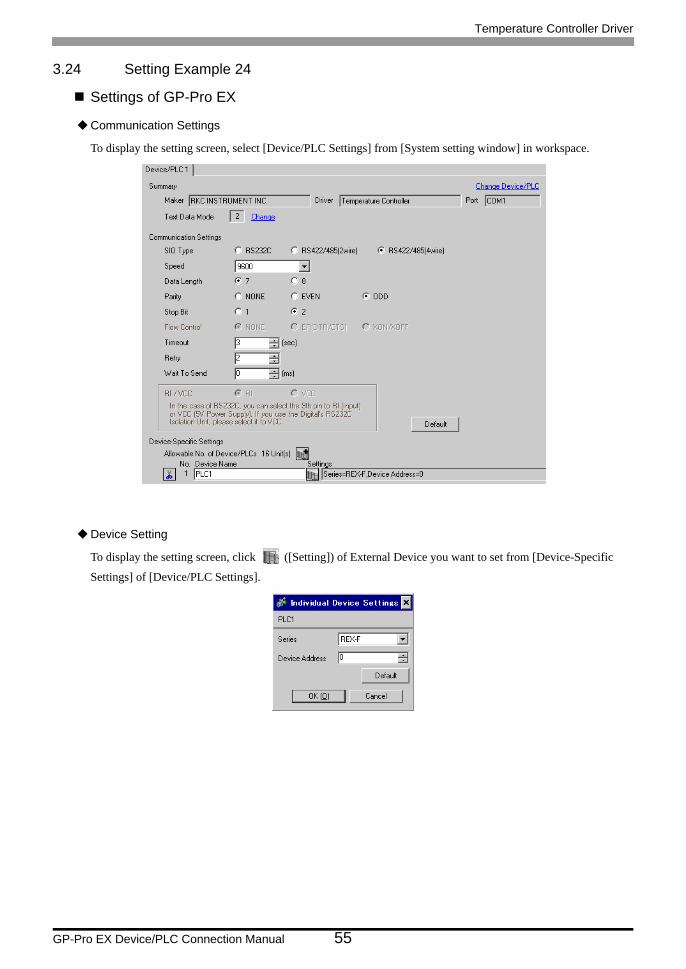
3.24 Setting Example 24
Settings of GP-Pro EX
Communication Settings
To display the setting screen, select [Device/PLC Settings] from [System setting window] in workspace.
Device Setting
To display the setting screen, click ([Setting]) of External Device you want to set from [Device-Specific
Settings] of [Device/PLC Settings].

Temperature Controller Driver
GP-Pro EX Device/PLC Connection Manual 56
Settings of External DeviceCommunication setting of the external device is set with the SEL, MODE, UP and Down keys located on the front
face of the temperature controller.
Please refer to the temperature controller manual for details.
Procedure
1. Set the external device to the operation STOP status.
Press the MODE key several times to display "Operation execution (RUN) /STOP transfer," and press the
Down key to set the mode to STOP.
2. Press the SET key to call up the set operator level 1.
3. Depress the SET key for 5 seconds or more to call up the set operator level 2.
4. Depress the SET key for 5 seconds or more to call up the engineer level.
5. Press the Down key several times to display PG24.
6. Press the SET key to display the set contents. Every time the SET key is depressed, item to be set switches.
7. Input the set contents with the Up/Down key, and press the SET key.
8. Press the MODE key to display "Operation execution (RUN)/STOP transfer," and press the Up key to set the
mode to RUN.
Setting valueAdd 0bPS 3bIT 11
• Parameters to be set differ per temperature controller. Please refer to the temperature controller manual for details.
Temperature Controller Driver
GP-Pro EX Device/PLC Connection Manual 57
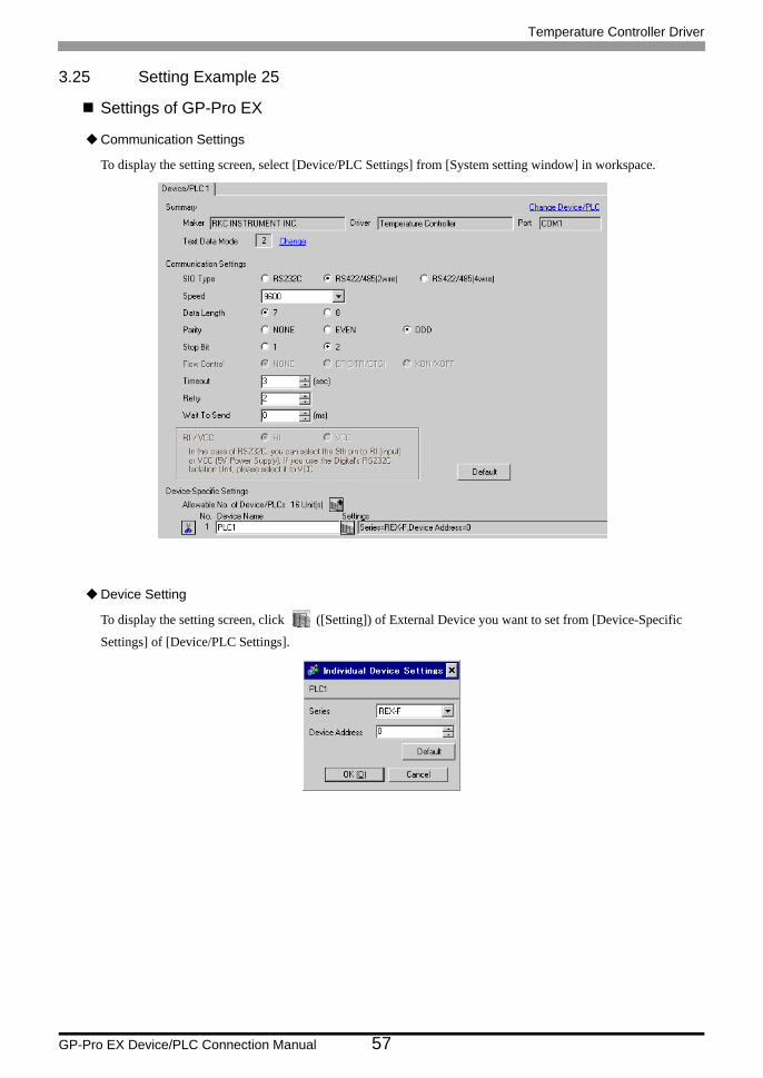
3.25 Setting Example 25
Settings of GP-Pro EX
Communication Settings
To display the setting screen, select [Device/PLC Settings] from [System setting window] in workspace.
Device Setting
To display the setting screen, click ([Setting]) of External Device you want to set from [Device-Specific
Settings] of [Device/PLC Settings].
Temperature Controller Driver
GP-Pro EX Device/PLC Connection Manual 58
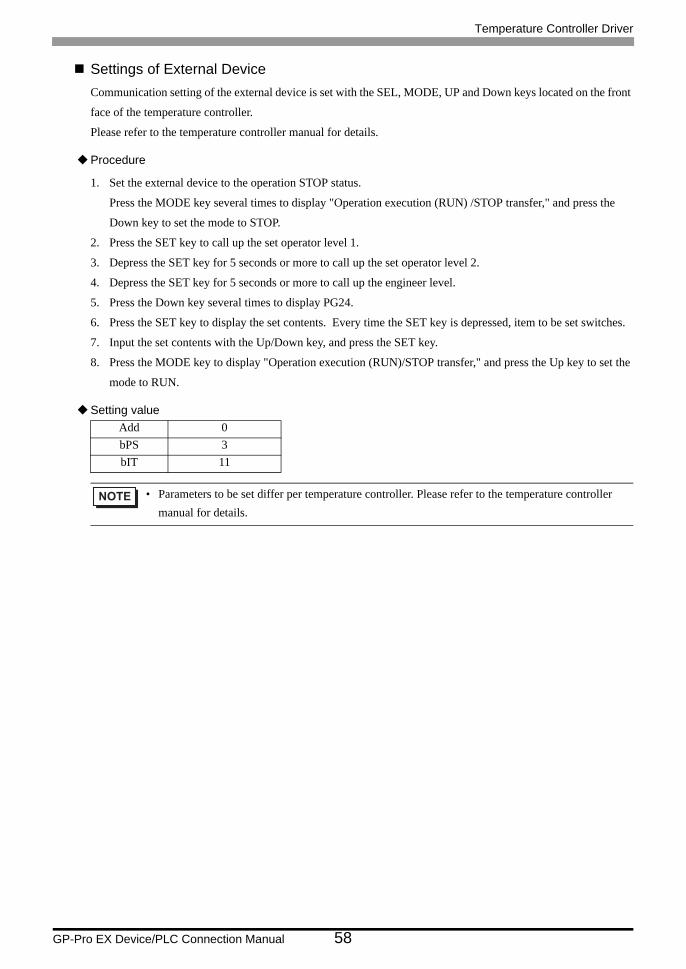
Settings of External DeviceCommunication setting of the external device is set with the SEL, MODE, UP and Down keys located on the front
face of the temperature controller.
Please refer to the temperature controller manual for details.
Procedure
1. Set the external device to the operation STOP status.
Press the MODE key several times to display "Operation execution (RUN) /STOP transfer," and press the
Down key to set the mode to STOP.
2. Press the SET key to call up the set operator level 1.
3. Depress the SET key for 5 seconds or more to call up the set operator level 2.
4. Depress the SET key for 5 seconds or more to call up the engineer level.
5. Press the Down key several times to display PG24.
6. Press the SET key to display the set contents. Every time the SET key is depressed, item to be set switches.
7. Input the set contents with the Up/Down key, and press the SET key.
8. Press the MODE key to display "Operation execution (RUN)/STOP transfer," and press the Up key to set the
mode to RUN.
Setting valueAdd 0bPS 3bIT 11
• Parameters to be set differ per temperature controller. Please refer to the temperature controller manual for details.
Temperature Controller Driver
GP-Pro EX Device/PLC Connection Manual 59
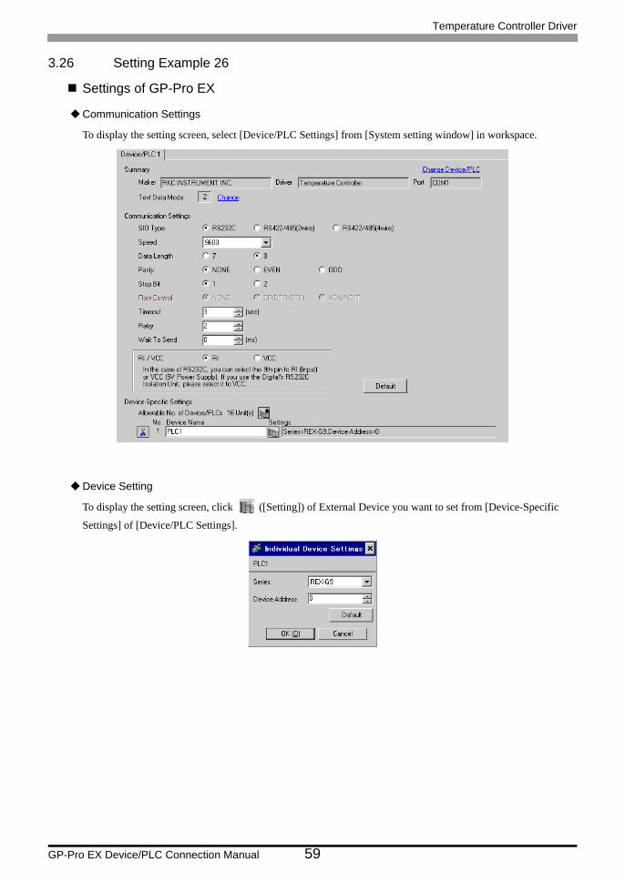
3.26 Setting Example 26
Settings of GP-Pro EX
Communication Settings
To display the setting screen, select [Device/PLC Settings] from [System setting window] in workspace.
Device Setting
To display the setting screen, click ([Setting]) of External Device you want to set from [Device-Specific
Settings] of [Device/PLC Settings].
Temperature Controller Driver
GP-Pro EX Device/PLC Connection Manual 60
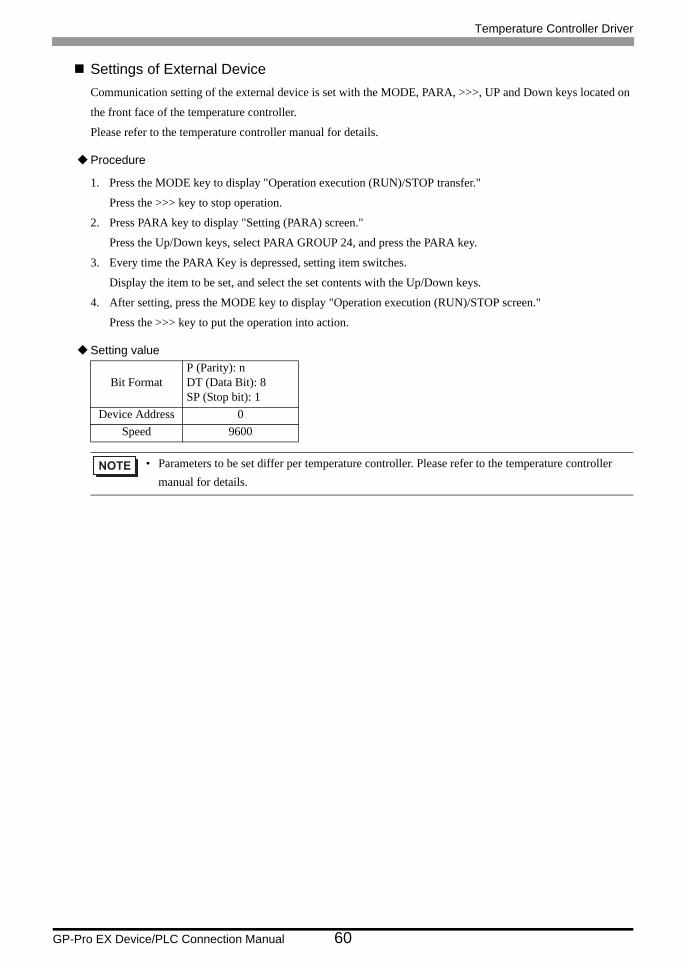
Settings of External DeviceCommunication setting of the external device is set with the MODE, PARA, >>>, UP and Down keys located on
the front face of the temperature controller.
Please refer to the temperature controller manual for details.
Procedure
1. Press the MODE key to display "Operation execution (RUN)/STOP transfer."
Press the >>> key to stop operation.
2. Press PARA key to display "Setting (PARA) screen."
Press the Up/Down keys, select PARA GROUP 24, and press the PARA key.
3. Every time the PARA Key is depressed, setting item switches.
Display the item to be set, and select the set contents with the Up/Down keys.
4. After setting, press the MODE key to display "Operation execution (RUN)/STOP screen."
Press the >>> key to put the operation into action.
Setting value
Bit FormatP (Parity): nDT (Data Bit): 8SP (Stop bit): 1
Device Address 0Speed 9600
• Parameters to be set differ per temperature controller. Please refer to the temperature controller manual for details.

Temperature Controller Driver
GP-Pro EX Device/PLC Connection Manual 61
3.27 Setting Example 27
Settings of GP-Pro EX
Communication Settings
To display the setting screen, select [Device/PLC Settings] from [System setting window] in workspace.
Device Setting
To display the setting screen, click ([Setting]) of External Device you want to set from [Device-Specific
Settings] of [Device/PLC Settings].

Temperature Controller Driver
GP-Pro EX Device/PLC Connection Manual 62
Settings of External DeviceCommunication setting of the external device is set with the MODE, PARA, >>>, UP and Down keys located on
the front face of the temperature controller.
Please refer to the temperature controller manual for details.
Procedure
1. Press the MODE key to display "Operation execution (RUN)/STOP transfer."
Press the >>> key to stop operation.
2. Press PARA key to display "Setting (PARA) screen."
Press the Up/Down keys, select PARA GROUP 24, and press the PARA key.
3. Every time the PARA Key is depressed, setting item switches.
Display the item to be set, and select the set contents with the Up/Down keys.
4. After setting, press the MODE key to display "Operation execution (RUN)/STOP screen."
Press the >>> key to put the operation into action.
Setting value
Bit FormatP (Parity): nDT (Data Bit): 8SP (Stop bit): 1
Device Address 0Speed 9600
• Parameters to be set differ per temperature controller. Please refer to the temperature controller manual for details.

Temperature Controller Driver
GP-Pro EX Device/PLC Connection Manual 63
3.28 Setting Example 28
Settings of GP-Pro EX
Communication Settings
To display the setting screen, select [Device/PLC Settings] from [System setting window] in workspace.
Device Setting
To display the setting screen, click ([Setting]) of External Device you want to set from [Device-Specific
Settings] of [Device/PLC Settings].

Temperature Controller Driver
GP-Pro EX Device/PLC Connection Manual 64
Settings of External DeviceCommunication setting of the external device is set with the MODE, PARA, >>>, UP and Down keys located on
the front face of the temperature controller.
Please refer to the temperature controller manual for details.
Procedure
1. Press the MODE key to display "Operation execution (RUN)/STOP transfer."
Press the >>> key to stop operation.
2. Press PARA key to display "Setting (PARA) screen."
Press the Up/Down keys, select PARA GROUP 24, and press the PARA key.
3. Every time the PARA Key is depressed, setting item switches.
Display the item to be set, and select the set contents with the Up/Down keys.
4. After setting, press the MODE key to display "Operation execution (RUN)/STOP screen."
Press the >>> key to put the operation into action.
Setting value
Bit FormatP (Parity): nDT (Data Bit): 8SP (Stop bit): 1
Device Address 0Speed 9600
• Parameters to be set differ per temperature controller. Please refer to the temperature controller manual for details.

Temperature Controller Driver
GP-Pro EX Device/PLC Connection Manual 65
3.29 Setting Example 29
Settings of GP-Pro EX
Communication Settings
To display the setting screen, select [Device/PLC Settings] from [System setting window] in workspace.
Device Setting
To display the setting screen, click ([Setting]) of External Device you want to set from [Device-Specific
Settings] of [Device/PLC Settings].
Temperature Controller Driver
GP-Pro EX Device/PLC Connection Manual 66
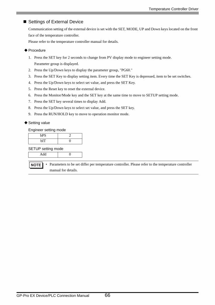
Settings of External DeviceCommunication setting of the external device is set with the SET, MODE, UP and Down keys located on the front
face of the temperature controller.
Please refer to the temperature controller manual for details.
Procedure
1. Press the SET key for 2 seconds to change from PV display mode to engineer setting mode.
Parameter group is displayed.
2. Press the Up/Down keys to display the parameter group, "PG60."
3. Press the SET Key to display setting item. Every time the SET Key is depressed, item to be set switches.
4. Press the Up/Down keys to select set value, and press the SET Key.
5. Press the Reset key to reset the external device.
6. Press the Monitor/Mode key and the SET key at the same time to move to SETUP setting mode.
7. Press the SET key several times to display Add.
8. Press the Up/Down keys to select set value, and press the SET key.
9. Press the RUN/HOLD key to move to operation monitor mode.
Setting value
Engineer setting mode
SETUP setting mode
bPS 2bIT 0
Add 0
• Parameters to be set differ per temperature controller. Please refer to the temperature controller manual for details.

Temperature Controller Driver
GP-Pro EX Device/PLC Connection Manual 67
3.30 Setting Example 30
Settings of GP-Pro EX
Communication Settings
To display the setting screen, select [Device/PLC Settings] from [System setting window] in workspace.
Device Setting
To display the setting screen, click ([Setting]) of External Device you want to set from [Device-Specific
Settings] of [Device/PLC Settings].

Temperature Controller Driver
GP-Pro EX Device/PLC Connection Manual 68
Settings of External DeviceCommunication setting of the external device is set with the SET, MODE, UP and Down keys located on the front
face of the temperature controller.
Please refer to the temperature controller manual for details.
Procedure
1. Press the SET key for 2 seconds to change from PV display mode to engineer setting mode.
Parameter group is displayed.
2. Press the Up/Down keys to display the parameter group, "PG60."
3. Press the SET Key to display setting item. Every time the SET Key is depressed, item to be set switches.
4. Press the Up/Down keys to select set value, and press the SET Key.
5. Press the Reset key to reset the external device.
6. Press the Monitor/Mode key and the SET key at the same time to move to SETUP setting mode.
7. Press the SET key several times to display Add.
8. Press the Up/Down keys to select set value, and press the SET key.
9. Press the RUN/HOLD key to move to operation monitor mode.
Setting value
Engineer setting mode
SETUP setting mode
bPS 2bIT 0
Add 0
• Parameters to be set differ per temperature controller. Please refer to the temperature controller manual for details.

Temperature Controller Driver
GP-Pro EX Device/PLC Connection Manual 69
3.31 Setting Example 31
Settings of GP-Pro EX
Communication Settings
To display the setting screen, select [Device/PLC Settings] from [System setting window] in workspace.
Device Setting
To display the setting screen, click ([Setting]) of External Device you want to set from [Device-Specific
Settings] of [Device/PLC Settings].

Temperature Controller Driver
GP-Pro EX Device/PLC Connection Manual 70
Settings of External DeviceCommunication setting of the external device is set with the SET, MODE, UP and Down keys located on the front
face of the temperature controller.
Please refer to the temperature controller manual for details.
Procedure
1. Press the SET key for 2 seconds to change from PV display mode to engineer setting mode.
Parameter group is displayed.
2. Press the Up/Down keys to display the parameter group, "PG60."
3. Press the SET Key to display setting item. Every time the SET Key is depressed, item to be set switches.
4. Press the Up/Down keys to select set value, and press the SET Key.
5. Press the Reset key to reset the external device.
6. Press the Monitor/Mode key and the SET key at the same time to move to SETUP setting mode.
7. Press the SET key several times to display Add.
8. Press the Up/Down keys to select set value, and press the SET key.
9. Press the RUN/HOLD key to move to operation monitor mode.
Setting value
Engineer setting mode
SETUP setting mode
bPS 2bIT 0
Add 0
• Parameters to be set differ per temperature controller. Please refer to the temperature controller manual for details.
Temperature Controller Driver
GP-Pro EX Device/PLC Connection Manual 71
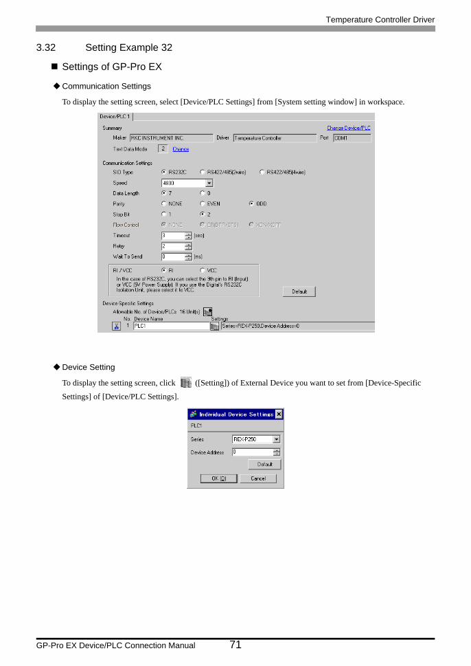
3.32 Setting Example 32
Settings of GP-Pro EX
Communication Settings
To display the setting screen, select [Device/PLC Settings] from [System setting window] in workspace.
Device Setting
To display the setting screen, click ([Setting]) of External Device you want to set from [Device-Specific
Settings] of [Device/PLC Settings].

Temperature Controller Driver
GP-Pro EX Device/PLC Connection Manual 72
Settings of External DeviceCommunication setting of the external device is set with the SET, UP and Down keys located on the front face of
the temperature controller.
Please refer to the temperature controller manual for details.
Procedure
1. While lifting up the stopper located at the lower section of the external device with a finger, pull and remove
it from the case.
2. Turn on the internal switch A at upper external device and put it back in the case.
3. Press the SET key to display the item to be set, and select the set contents with the Up/Down keys. Stop bit,
data bit, and parity bit are displayed in a 3 digit character string at the setting item, bIT, so touch each one's
digit, ten's digit, and hundred's digit on the SV indicator, and select the set contents with the Up/Down keys.
4. Press the SET key to set the set contents.
5. Remove the external device form the case, turn OFF the internal switch A mentioned in 2 above, and return it
to the case.
Setting valuebPS 4800bIT o72Add 0
• Parameters to be set differ per temperature controller. Please refer to the temperature controller manual for details.

Temperature Controller Driver
GP-Pro EX Device/PLC Connection Manual 73
3.33 Setting Example 33
Settings of GP-Pro EX
Communication Settings
To display the setting screen, select [Device/PLC Settings] from [System setting window] in workspace.
Device Setting
To display the setting screen, click ([Setting]) of External Device you want to set from [Device-Specific
Settings] of [Device/PLC Settings].
Temperature Controller Driver
GP-Pro EX Device/PLC Connection Manual 74
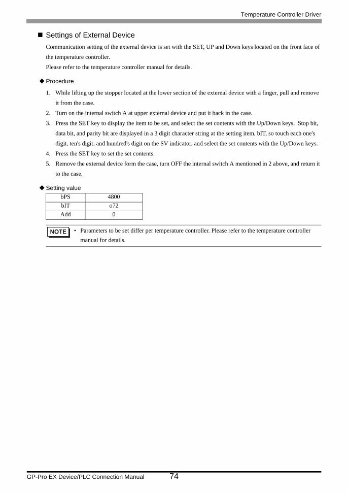
Settings of External DeviceCommunication setting of the external device is set with the SET, UP and Down keys located on the front face of
the temperature controller.
Please refer to the temperature controller manual for details.
Procedure
1. While lifting up the stopper located at the lower section of the external device with a finger, pull and remove
it from the case.
2. Turn on the internal switch A at upper external device and put it back in the case.
3. Press the SET key to display the item to be set, and select the set contents with the Up/Down keys. Stop bit,
data bit, and parity bit are displayed in a 3 digit character string at the setting item, bIT, so touch each one's
digit, ten's digit, and hundred's digit on the SV indicator, and select the set contents with the Up/Down keys.
4. Press the SET key to set the set contents.
5. Remove the external device form the case, turn OFF the internal switch A mentioned in 2 above, and return it
to the case.
Setting valuebPS 4800bIT o72Add 0
• Parameters to be set differ per temperature controller. Please refer to the temperature controller manual for details.

Temperature Controller Driver
GP-Pro EX Device/PLC Connection Manual 75
3.34 Setting Example 34
Settings of GP-Pro EX
Communication Settings
To display the setting screen, select [Device/PLC Settings] from [System setting window] in workspace.
Device Setting
To display the setting screen, click ([Setting]) of External Device you want to set from [Device-Specific
Settings] of [Device/PLC Settings].

Temperature Controller Driver
GP-Pro EX Device/PLC Connection Manual 76
Settings of External DeviceCommunication setting of the external device is set with the SEL, MODE, UP and Down keys located on the front
face of the temperature controller.
Please refer to the temperature controller manual for details.
Procedure
1. Depress the SEL key for 2 seconds to change from PV display mode to engineer setting mode.
Parameter group is displayed.
2. Press the Up/Down keys to display the parameter group, "PG9."
3. Press the SEL key to display the setting item. Every time the SEL key is depressed, setting item switches.
4. Press the Up/Down keys to display the setting value.
5. Press the Up/Down keys to select the setting value, and press the SEL key.
6. Press the Monitor/Mode key to switch to the PV display mode.
7. Press the Monitor/Mode key and the SEL key at the same time to change from PV display mode to SETUP
setting mode.
8. Press the SEL key several times to display Add.
9. Press the Up/Down keys to display the setting value.
10. Press the Up/Down keys to display the setting value.
11. Press the Monitor/Mode keys to switch to the PV display mode.
Setting value
Engineer setting mode
SETUP setting mode
bPS 3bIT 0
Add 0
• Parameters to be set differ per temperature controller. Please refer to the temperature controller manual for details.

Temperature Controller Driver
GP-Pro EX Device/PLC Connection Manual 77
3.35 Setting Example 35
Settings of GP-Pro EX
Communication Settings
To display the setting screen, select [Device/PLC Settings] from [System setting window] in workspace.
Device Setting
To display the setting screen, click ([Setting]) of External Device you want to set from [Device-Specific
Settings] of [Device/PLC Settings].
Temperature Controller Driver
GP-Pro EX Device/PLC Connection Manual 78
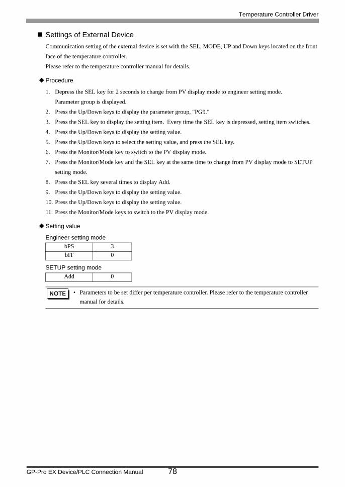
Settings of External DeviceCommunication setting of the external device is set with the SEL, MODE, UP and Down keys located on the front
face of the temperature controller.
Please refer to the temperature controller manual for details.
Procedure
1. Depress the SEL key for 2 seconds to change from PV display mode to engineer setting mode.
Parameter group is displayed.
2. Press the Up/Down keys to display the parameter group, "PG9."
3. Press the SEL key to display the setting item. Every time the SEL key is depressed, setting item switches.
4. Press the Up/Down keys to display the setting value.
5. Press the Up/Down keys to select the setting value, and press the SEL key.
6. Press the Monitor/Mode key to switch to the PV display mode.
7. Press the Monitor/Mode key and the SEL key at the same time to change from PV display mode to SETUP
setting mode.
8. Press the SEL key several times to display Add.
9. Press the Up/Down keys to display the setting value.
10. Press the Up/Down keys to display the setting value.
11. Press the Monitor/Mode keys to switch to the PV display mode.
Setting value
Engineer setting mode
SETUP setting mode
bPS 3bIT 0
Add 0
• Parameters to be set differ per temperature controller. Please refer to the temperature controller manual for details.

Temperature Controller Driver
GP-Pro EX Device/PLC Connection Manual 79
3.36 Setting Example 36
Settings of GP-Pro EX
Communication Settings
To display the setting screen, select [Device/PLC Settings] from [System setting window] in workspace.
Device Setting
To display the setting screen, click ([Setting]) of External Device you want to set from [Device-Specific
Settings] of [Device/PLC Settings].

Temperature Controller Driver
GP-Pro EX Device/PLC Connection Manual 80
Settings of External DeviceCommunication setting of the external device is set with the SEL, MODE, UP and Down keys located on the front
face of the temperature controller.
Please refer to the temperature controller manual for details.
Procedure
1. Depress the SEL key for 2 seconds to change from PV display mode to engineer setting mode.
Parameter group is displayed.
2. Press the Up/Down keys to display the parameter group, "PG6."
3. Press the SEL key to display the setting item. Every time the SEL key is depressed, setting item switches.
4. Press the Up/Down keys to display the setting value.
5. Press the Up/Down keys to select the setting value, and press the SEL key.
6. Press the Monitor/Mode key to switch to the PV display mode.
7. Press the Monitor/Mode key and the SEL key at the same time to change from PV display mode to SETUP
setting mode.
8. Press the SEL key several times to display Add.
9. Press the Up/Down keys to display the setting value.
10. Press the Up/Down keys to display the setting value.
11. Press the Monitor/Mode keys to switch to the PV display mode.
Setting value
Engineer setting mode
SETUP setting mode
bPS 3bIT 0
Add 0
• Parameters to be set differ per temperature controller. Please refer to the temperature controller manual for details.

Temperature Controller Driver
GP-Pro EX Device/PLC Connection Manual 81
3.37 Setting Example 37
Settings of GP-Pro EX
Communication Settings
To display the setting screen, select [Device/PLC Settings] from [System setting window] in workspace.
Device Setting
To display the setting screen, click ([Setting]) of External Device you want to set from [Device-Specific
Settings] of [Device/PLC Settings].

Temperature Controller Driver
GP-Pro EX Device/PLC Connection Manual 82
Settings of External DeviceCommunication setting of the external device is set with the SEL, MODE, UP and Down keys located on the front
face of the temperature controller.
Please refer to the temperature controller manual for details.
Procedure
1. Depress the SEL key for 2 seconds to change from PV display mode to engineer setting mode.
Parameter group is displayed.
2. Press the Up/Down keys to display the parameter group, "PG9."
3. Press the SEL key to display the setting item. Every time the SEL key is depressed, setting item switches.
4. Press the Up/Down keys to display the setting value.
5. Press the Up/Down keys to select the setting value, and press the SEL key.
6. Press the Monitor/Mode key to switch to the PV display mode.
7. Press the Monitor/Mode key and the SEL key at the same time to change from PV display mode to SETUP
setting mode.
8. Press the SEL key several times to display Add.
9. Press the Up/Down keys to display the setting value.
10. Press the Up/Down keys to display the setting value.
11. Press the Monitor/Mode keys to switch to the PV display mode.
Setting value
Engineer setting mode
SETUP setting mode
bPS 3bIT 0
Add 0
• Parameters to be set differ per temperature controller. Please refer to the temperature controller manual for details.
Temperature Controller Driver
GP-Pro EX Device/PLC Connection Manual 83
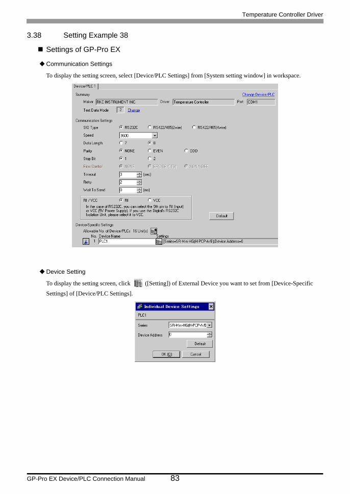
3.38 Setting Example 38
Settings of GP-Pro EX
Communication Settings
To display the setting screen, select [Device/PLC Settings] from [System setting window] in workspace.
Device Setting
To display the setting screen, click ([Setting]) of External Device you want to set from [Device-Specific
Settings] of [Device/PLC Settings].

Temperature Controller Driver
GP-Pro EX Device/PLC Connection Manual 84
Settings of External DeviceCommunication setting of the external device is set with the slave address setting switch on the front face of the
temperature controller and the dip switch in the temperature controller.
Please refer to the temperature controller manual for details.
Procedure
1. Set slave address for the host link with the slave address setting switch on the front face of the temperature
controller.
2. Remove the temperature controller from the mother block and set communication speed and data construction
with the dip switch in the temperature controller.
Setting value
Slave address setting switch
Dip switch
Upper Digit Setting 0Lower Digit Setting 0
Dip switch Setting Discription1 ON
Data construction2 ON3 ON
Communication speed4 OFF
• Parameters to be set differ per temperature controller. Please refer to the temperature controller manual for details.
Temperature Controller Driver
GP-Pro EX Device/PLC Connection Manual 85
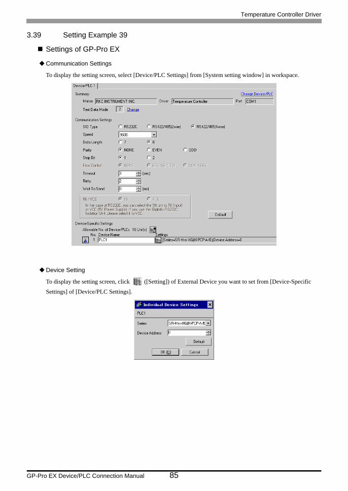
3.39 Setting Example 39
Settings of GP-Pro EX
Communication Settings
To display the setting screen, select [Device/PLC Settings] from [System setting window] in workspace.
Device Setting
To display the setting screen, click ([Setting]) of External Device you want to set from [Device-Specific
Settings] of [Device/PLC Settings].
Temperature Controller Driver
GP-Pro EX Device/PLC Connection Manual 86
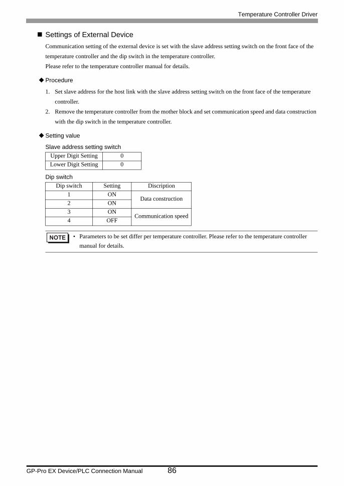
Settings of External DeviceCommunication setting of the external device is set with the slave address setting switch on the front face of the
temperature controller and the dip switch in the temperature controller.
Please refer to the temperature controller manual for details.
Procedure
1. Set slave address for the host link with the slave address setting switch on the front face of the temperature
controller.
2. Remove the temperature controller from the mother block and set communication speed and data construction
with the dip switch in the temperature controller.
Setting value
Slave address setting switch
Dip switch
Upper Digit Setting 0Lower Digit Setting 0
Dip switch Setting Discription1 ON
Data construction2 ON3 ON
Communication speed4 OFF
• Parameters to be set differ per temperature controller. Please refer to the temperature controller manual for details.
Temperature Controller Driver
GP-Pro EX Device/PLC Connection Manual 87
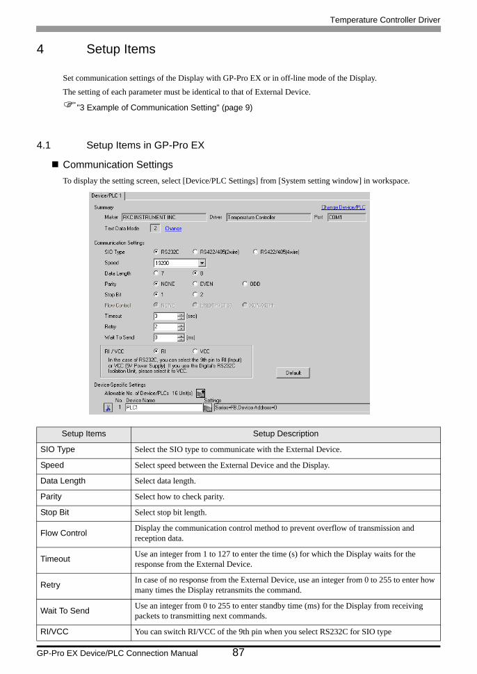
4 Setup Items
Set communication settings of the Display with GP-Pro EX or in off-line mode of the Display.
The setting of each parameter must be identical to that of External Device.
"3 Example of Communication Setting" (page 9)
4.1 Setup Items in GP-Pro EX
Communication SettingsTo display the setting screen, select [Device/PLC Settings] from [System setting window] in workspace.
Setup Items Setup Description
SIO Type Select the SIO type to communicate with the External Device.
Speed Select speed between the External Device and the Display.
Data Length Select data length.
Parity Select how to check parity.
Stop Bit Select stop bit length.
Flow Control Display the communication control method to prevent overflow of transmission and reception data.
Timeout Use an integer from 1 to 127 to enter the time (s) for which the Display waits for the response from the External Device.
Retry In case of no response from the External Device, use an integer from 0 to 255 to enter how many times the Display retransmits the command.
Wait To Send Use an integer from 0 to 255 to enter standby time (ms) for the Display from receiving packets to transmitting next commands.
RI/VCC You can switch RI/VCC of the 9th pin when you select RS232C for SIO type
Temperature Controller Driver
GP-Pro EX Device/PLC Connection Manual 88
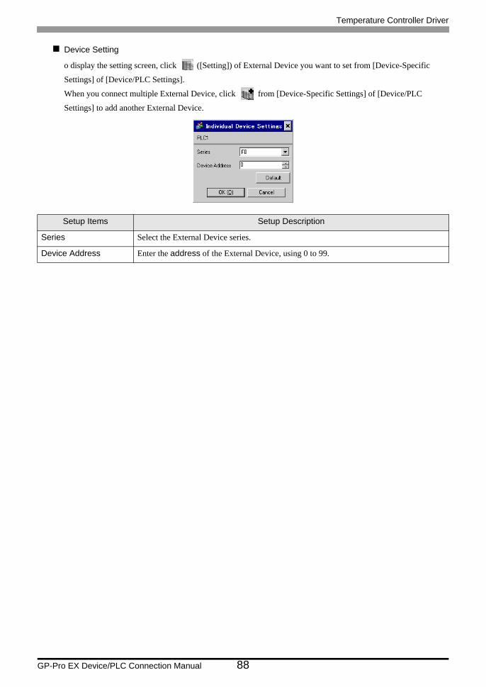
Device Setting
o display the setting screen, click ([Setting]) of External Device you want to set from [Device-Specific
Settings] of [Device/PLC Settings].
When you connect multiple External Device, click from [Device-Specific Settings] of [Device/PLC
Settings] to add another External Device.
Setup Items Setup Description
Series Select the External Device series.
Device Address Enter the address of the External Device, using 0 to 99.
Temperature Controller Driver
GP-Pro EX Device/PLC Connection Manual 89
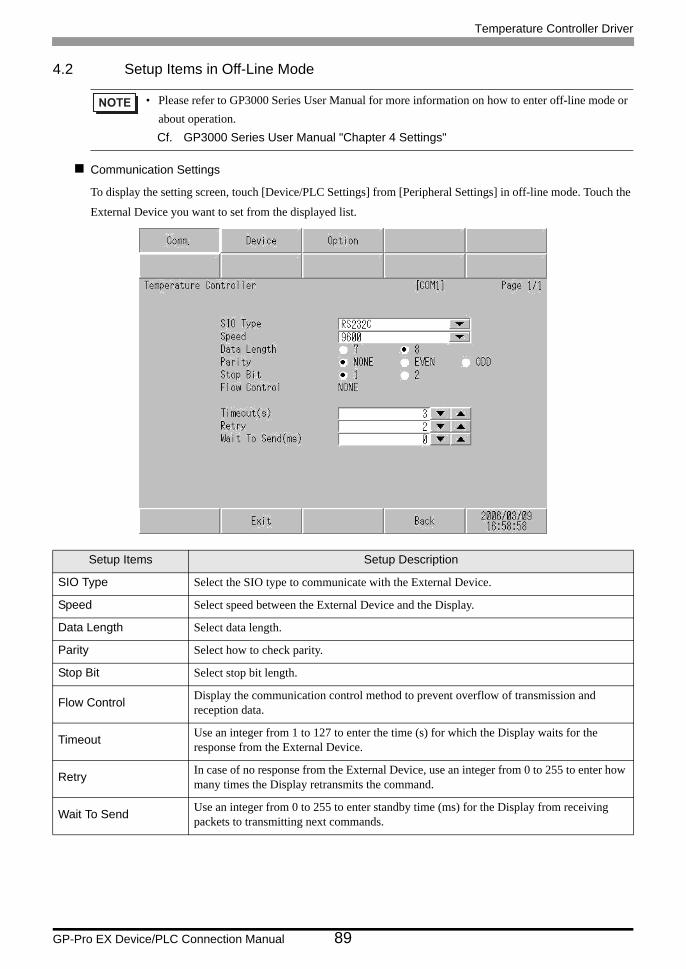
4.2 Setup Items in Off-Line Mode
Communication Settings
To display the setting screen, touch [Device/PLC Settings] from [Peripheral Settings] in off-line mode. Touch the
External Device you want to set from the displayed list.
• Please refer to GP3000 Series User Manual for more information on how to enter off-line mode or about operation.Cf. GP3000 Series User Manual "Chapter 4 Settings"
Setup Items Setup Description
SIO Type Select the SIO type to communicate with the External Device.
Speed Select speed between the External Device and the Display.
Data Length Select data length.
Parity Select how to check parity.
Stop Bit Select stop bit length.
Flow Control Display the communication control method to prevent overflow of transmission and reception data.
Timeout Use an integer from 1 to 127 to enter the time (s) for which the Display waits for the response from the External Device.
Retry In case of no response from the External Device, use an integer from 0 to 255 to enter how many times the Display retransmits the command.
Wait To Send Use an integer from 0 to 255 to enter standby time (ms) for the Display from receiving packets to transmitting next commands.
Temperature Controller Driver
GP-Pro EX Device/PLC Connection Manual 90
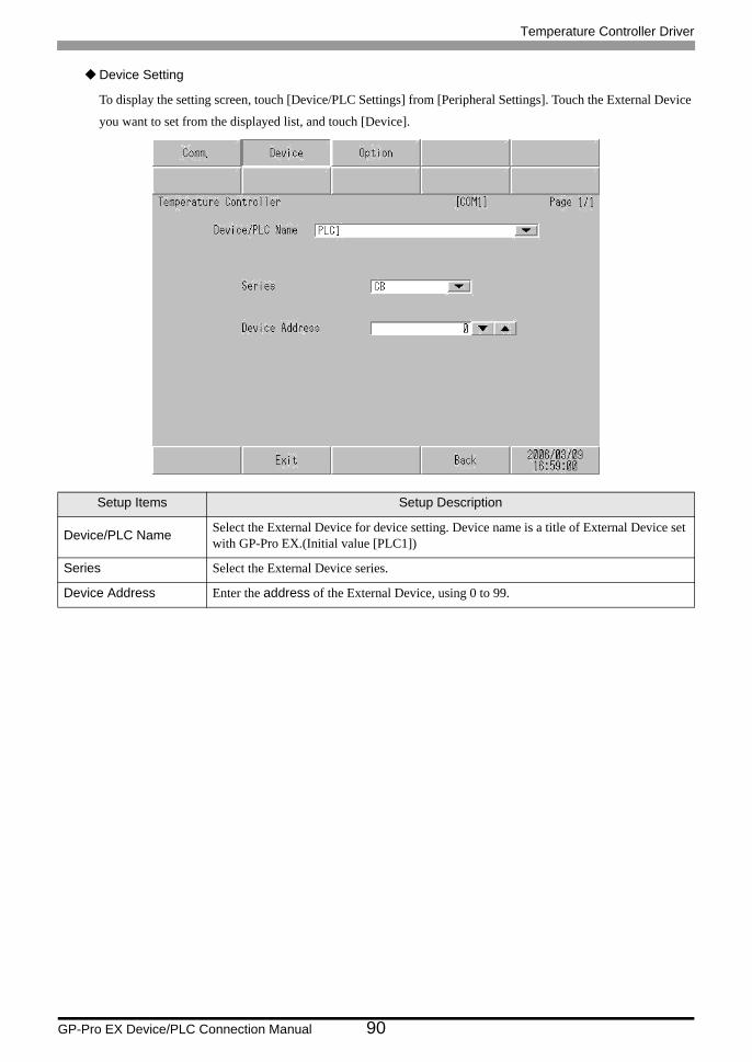
Device Setting
To display the setting screen, touch [Device/PLC Settings] from [Peripheral Settings]. Touch the External Device
you want to set from the displayed list, and touch [Device].
Setup Items Setup Description
Device/PLC Name Select the External Device for device setting. Device name is a title of External Device set with GP-Pro EX.(Initial value [PLC1])
Series Select the External Device series.
Device Address Enter the address of the External Device, using 0 to 99.
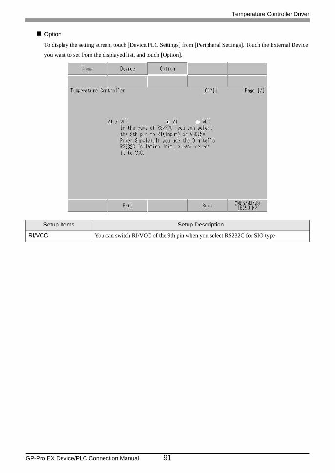
Temperature Controller Driver
GP-Pro EX Device/PLC Connection Manual 91
Option
To display the setting screen, touch [Device/PLC Settings] from [Peripheral Settings]. Touch the External Device
you want to set from the displayed list, and touch [Option].
Setup Items Setup Description
RI/VCC You can switch RI/VCC of the 9th pin when you select RS232C for SIO type
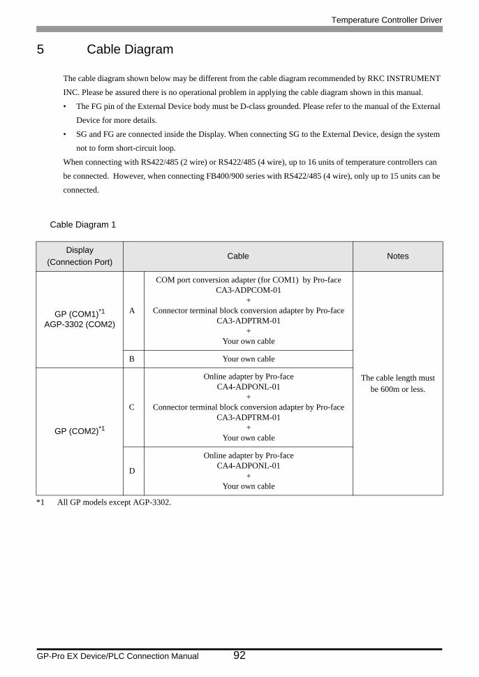
Temperature Controller Driver
GP-Pro EX Device/PLC Connection Manual 92
5 Cable Diagram
The cable diagram shown below may be different from the cable diagram recommended by RKC INSTRUMENT
INC. Please be assured there is no operational problem in applying the cable diagram shown in this manual.
• The FG pin of the External Device body must be D-class grounded. Please refer to the manual of the External
Device for more details.
• SG and FG are connected inside the Display. When connecting SG to the External Device, design the system
not to form short-circuit loop.
When connecting with RS422/485 (2 wire) or RS422/485 (4 wire), up to 16 units of temperature controllers can
be connected. However, when connecting FB400/900 series with RS422/485 (4 wire), only up to 15 units can be
connected.
Cable Diagram 1
Display(Connection Port)
Cable Notes
GP (COM1)*1AGP-3302 (COM2)
*1 All GP models except AGP-3302.
A
COM port conversion adapter (for COM1) by Pro-faceCA3-ADPCOM-01
+Connector terminal block conversion adapter by Pro-face
CA3-ADPTRM-01+
Your own cable
The cable length must be 600m or less.
B Your own cable
GP (COM2)*1
C
Online adapter by Pro-faceCA4-ADPONL-01
+Connector terminal block conversion adapter by Pro-face
CA3-ADPTRM-01+
Your own cable
D
Online adapter by Pro-faceCA4-ADPONL-01
+Your own cable
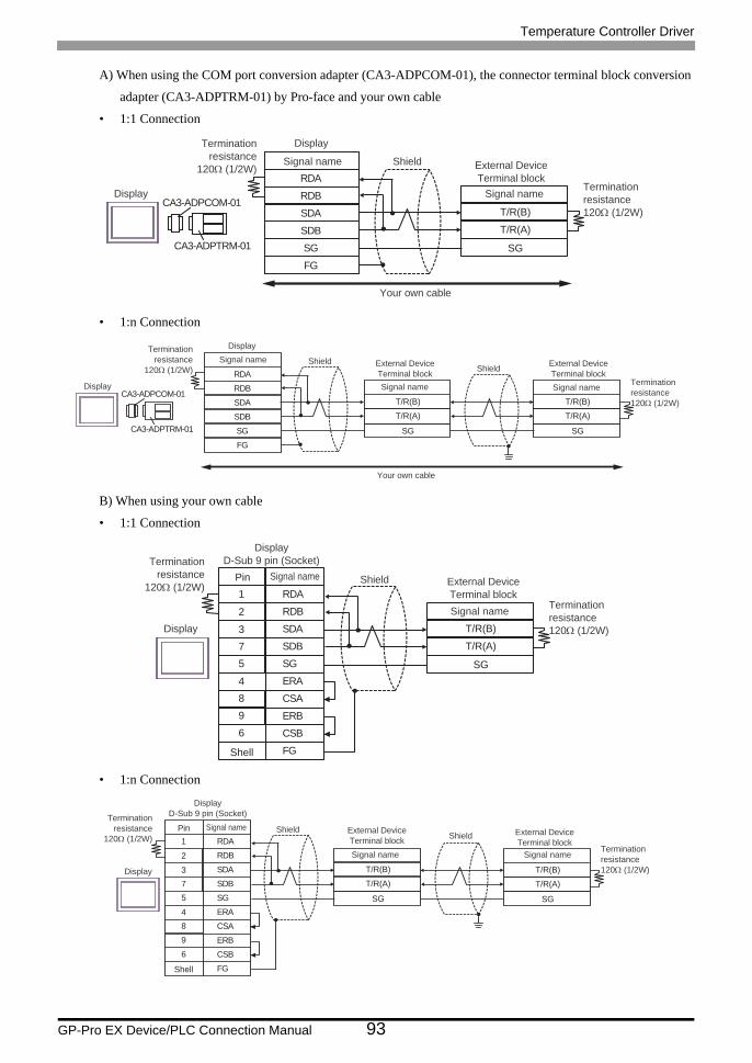
Temperature Controller Driver
GP-Pro EX Device/PLC Connection Manual 93
A) When using the COM port conversion adapter (CA3-ADPCOM-01), the connector terminal block conversion
adapter (CA3-ADPTRM-01) by Pro-face and your own cable
• 1:1 Connection
• 1:n Connection
B) When using your own cable
• 1:1 Connection
• 1:n Connection
RDB
SDBSGFG
CA3-ADPCOM-01
CA3-ADPTRM-01
RDA
SDA T/R(B)
T/R(A)
SG
Terminationresistance
120Ω (1/2W)
Terminationresistance120Ω (1/2W)
Your own cable
Display
Display
External DeviceTerminal block
ShieldSignal name
Signal name
RDB
SDBSGFG
CA3-ADPCOM-01
CA3-ADPTRM-01
RDA
SDA T/R(B)
T/R(A)
SG
T/R(B)
T/R(A)
SG
Terminationresistance
120Ω (1/2W)Terminationresistance120Ω (1/2W)
Your own cable
Display
Display
External DeviceTerminal block
External DeviceTerminal block
ShieldShield
Signal name Signal name
Signal name
SDA3
RDB2
SG5
4 ERA
SDB
ERB
7
9
CSB6
Shell FG
RDA1Pin
CSA8
T/R(B)
T/R(A)
SG
Terminationresistance
120Ω (1/2W)
Terminationresistance120Ω (1/2W)
DisplayD-Sub 9 pin (Socket)
External DeviceTerminal block
Shield
Signal name
Signal name
Display
Shell
SDA3
RDB2
SG5
4 ERA
SDB
ERB
7
9
CSB6
FG
RDA1
CSA8
T/R(B)
T/R(A)
SG
T/R(B)
T/R(A)
SG
Terminationresistance
120Ω (1/2W)Terminationresistance120Ω (1/2W)
DisplayD-Sub 9 pin (Socket)
External DeviceTerminal block
External DeviceTerminal block
ShieldShield
Signal name Signal name
Pin Signal name
Display
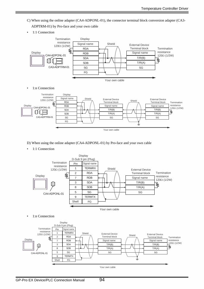
Temperature Controller Driver
GP-Pro EX Device/PLC Connection Manual 94
C) When using the online adapter (CA4-ADPONL-01), the connector terminal block conversion adapter (CA3-
ADPTRM-01) by Pro-face and your own cable
• 1:1 Connection
• 1:n Connection
D) When using the online adapter (CA4-ADPONL-01) by Pro-face and your own cable
• 1:1 Connection
• 1:n Connection
RDB
SDBSGFG
CA4-ADPONL-01
CA3-ADPTRM-01
RDA
SDA T/R(B)
T/R(A)
SG
Terminationresistance
120Ω (1/2W)Terminationresistance120Ω (1/2W)
Display
Display
External DeviceTerminal block
ShieldSignal name
Signal name
Your own cable
RDB
SDBSGFG
CA4-ADPONL-01
CA3-ADPTRM-01
RDA
SDA T/R(B)
T/R(A)
SG
T/R(B)
T/R(A)
SG
Terminationresistance
120Ω (1/2W)Terminationresistance120Ω (1/2W)
Your own cable
Display
Display
External DeviceTerminal block
External DeviceTerminal block
ShieldShield
Signal name Signal name
Signal name
CA4-ADPONL-01
RDB7
RDA2
SDB8
9 TERMTX
SDA
FG
3
TERMRX1
SG5
T/R(B)
T/R(A)
SG
Your own cable
Shell
PinTerminationresistance
120Ω (1/2W)Terminationresistance120Ω (1/2W)
DisplayD-Sub 9 pin (Plug)
External DeviceTerminal block
Shield
Signal name
Signal name
Display
CA4-ADPONL-01
RDB7
RDA2
SDB8
9 TERMTX
SDA
FG
3
TERMRX1
SG5
T/R(B)
T/R(A)
SG
T/R(B)
T/R(A)
SG
Your own cable
Shell
Terminationresistance
120Ω (1/2W)Terminationresistance120Ω (1/2W)
DisplayD-Sub 9 pin (Plug)
External DeviceTerminal block
External DeviceTerminal block
ShieldShield
Signal name Signal name
Pin Signal name
Display
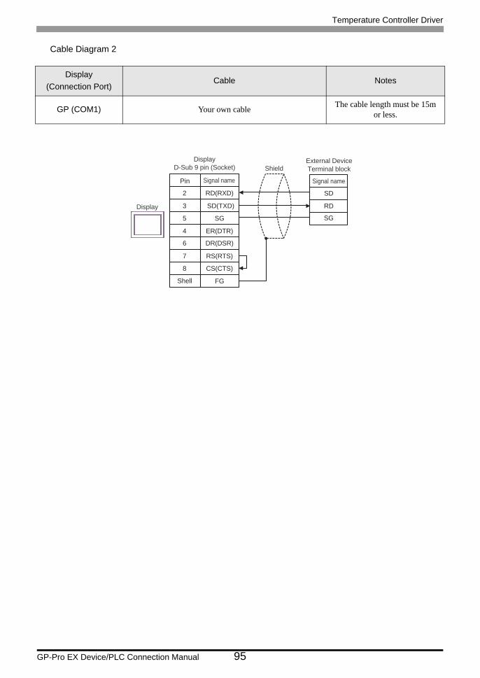
Temperature Controller Driver
GP-Pro EX Device/PLC Connection Manual 95
Cable Diagram 2
Display(Connection Port)
Cable Notes
GP (COM1) Your own cable The cable length must be 15m or less.
SD(TXD)3
RD(RXD)2
SG5
SD
RD
4 ER(DTR)
SG
RS(RTS)
CS(CTS)
7
8
DR(DSR)6
FGShell
DisplayD-Sub 9 pin (Socket)
External DeviceTerminal blockShield
Display
Pin Signal nameSignal name
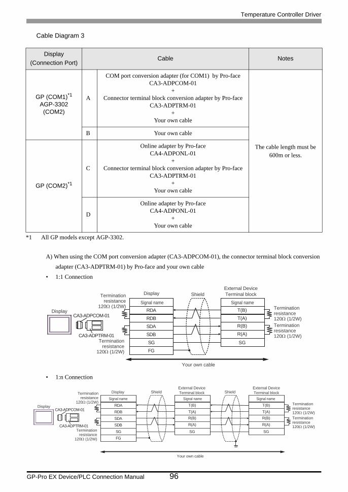
Temperature Controller Driver
GP-Pro EX Device/PLC Connection Manual 96
Cable Diagram 3
A) When using the COM port conversion adapter (CA3-ADPCOM-01), the connector terminal block conversion
adapter (CA3-ADPTRM-01) by Pro-face and your own cable
• 1:1 Connection
• 1:n Connection
Display(Connection Port)
Cable Notes
GP (COM1)*1AGP-3302 (COM2)
*1 All GP models except AGP-3302.
A
COM port conversion adapter (for COM1) by Pro-faceCA3-ADPCOM-01
+Connector terminal block conversion adapter by Pro-face
CA3-ADPTRM-01+
Your own cable
The cable length must be 600m or less.
B Your own cable
GP (COM2)*1
C
Online adapter by Pro-faceCA4-ADPONL-01
+Connector terminal block conversion adapter by Pro-face
CA3-ADPTRM-01+
Your own cable
D
Online adapter by Pro-faceCA4-ADPONL-01
+Your own cable
RDB
SDBSGFG
CA3-ADPCOM-01
CA3-ADPTRM-01
RDA
SDA
T(B)
T(A)R(B)
R(A)
SG
External DeviceTerminal blockShield
Display
Signal name Signal nameTermination
resistance120Ω (1/2W) Termination
resistance120Ω (1/2W)Terminationresistance120Ω (1/2W)
Terminationresistance
120Ω (1/2W)
Display
Your own cable
RDB
SDBSGFG
CA3-ADPCOM-01
CA3-ADPTRM-01
RDA
SDA
T(B)
T(A)R(B)
R(A)
SG
T(B)
T(A)R(B)
R(A)
SG
External DeviceTerminal block
External DeviceTerminal blockShield Shield
Display
Signal name Signal name Signal nameTerminationresistance120Ω (1/2W)Terminationresistance120Ω (1/2W)
Terminationresistance
120Ω (1/2W)
Terminationresistance
120Ω (1/2W)
Display
Your own cable
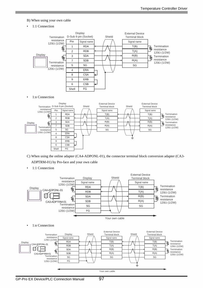
Temperature Controller Driver
GP-Pro EX Device/PLC Connection Manual 97
B) When using your own cable
• 1:1 Connection
• 1:n Connection
C) When using the online adapter (CA4-ADPONL-01), the connector terminal block conversion adapter (CA3-
ADPTRM-01) by Pro-face and your own cable
• 1:1 Connection
• 1:n Connection
SDA3
RDB2
SG5
4 ERA
SDB
ERB
7
9
CSB6FG
RDA1
CSA8
T(B)
T(A)R(B)
R(A)
SG
Shell
DisplayD-Sub 9 pin (Socket)
External DeviceTerminal blockShield
Display
Pin Signal nameSignal nameTerminationresistance120Ω (1/2W)Terminationresistance120Ω (1/2W)
Terminationresistance
120Ω (1/2W)
Terminationresistance
120Ω (1/2W)
SDA3
RDB2
SG5
4 ERA
SDB
ERB
7
9
CSB6
FG
RDA1
CSA8
T(B)
T(A)R(B)
R(A)
SG
T(B)
T(A)R(B)
R(A)
SG
Shell
DisplayD-Sub 9 pin (Socket)
External DeviceTerminal block
External DeviceTerminal blockShield Shield
Display
Pin Signal name Signal nameSignal nameTerminationresistance120Ω (1/2W)Terminationresistance120Ω (1/2W)
Terminationresistance
120Ω (1/2W)
Terminationresistance
120Ω (1/2W)
RDB
SDBSGFG
CA4-ADPONL-01
CA3-ADPTRM-01
RDA
SDA
T(B)
T(A)R(B)
R(A)
SG
External DeviceTerminal blockShield
Display
DisplaySignal name Signal name
Terminationresistance120Ω (1/2W)Terminationresistance120Ω (1/2W)
Terminationresistance
120Ω (1/2W)
Terminationresistance
120Ω (1/2W)
Your own cable
RDB
SDBSGFG
CA4-ADPONL-01
CA3-ADPTRM-01
RDA
SDA
T(B)
T(A)R(B)
R(A)
SG
T(B)
T(A)R(B)
R(A)
SG
External DeviceTerminal block
External DeviceTerminal blockShield ShieldDisplay
Display
Signal name Signal name Signal nameTerminationresistance120Ω (1/2W)Terminationresistance120Ω (1/2W)
Terminationresistance
120Ω (1/2W)
Terminationresistance
120Ω (1/2W)
Your own cable
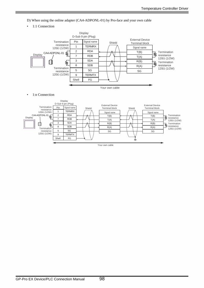
Temperature Controller Driver
GP-Pro EX Device/PLC Connection Manual 98
D) When using the online adapter (CA4-ADPONL-01) by Pro-face and your own cable
• 1:1 Connection
• 1:n Connection
CA4-ADPONL-01RDB7
RDA2
SDB8
9 TERMTX
SDA
FG
3
TERMRX1
SG5
T(B)
T(A)R(B)
R(A)
SG
External DeviceTerminal blockShield
Display
Signal nameTerminationresistance120Ω (1/2W)Terminationresistance120Ω (1/2W)
Terminationresistance
120Ω (1/2W)
Terminationresistance
120Ω (1/2W)
Shell
DisplayD-Sub 9 pin (Plug)
Pin Signal name
Your own cable
CA4-ADPONL-01RDB7
RDA2
SDB8
9 TERMTX
SDA
FG
3
TERMRX1
SG5
T(B)
T(A)R(B)
R(A)
SG
T(B)
T(A)R(B)
R(A)
SG
External DeviceTerminal block
External DeviceTerminal blockShield Shield
DisplayTerminationresistance120Ω (1/2W)Terminationresistance120Ω (1/2W)
Terminationresistance
120Ω (1/2W)
Terminationresistance
120Ω (1/2W)
Shell
DisplayD-Sub 9 pin (Plug)
Your own cable
Signal name Signal name
Pin Signal name
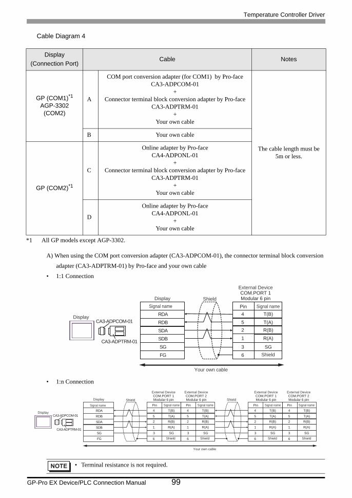
Temperature Controller Driver
GP-Pro EX Device/PLC Connection Manual 99
Cable Diagram 4
A) When using the COM port conversion adapter (CA3-ADPCOM-01), the connector terminal block conversion
adapter (CA3-ADPTRM-01) by Pro-face and your own cable
• 1:1 Connection
• 1:n Connection
Display(Connection Port)
Cable Notes
GP (COM1)*1AGP-3302 (COM2)
*1 All GP models except AGP-3302.
A
COM port conversion adapter (for COM1) by Pro-faceCA3-ADPCOM-01
+Connector terminal block conversion adapter by Pro-face
CA3-ADPTRM-01+
Your own cable
The cable length must be 5m or less.
B Your own cable
GP (COM2)*1
C
Online adapter by Pro-faceCA4-ADPONL-01
+Connector terminal block conversion adapter by Pro-face
CA3-ADPTRM-01+
Your own cable
D
Online adapter by Pro-faceCA4-ADPONL-01
+Your own cable
• Terminal resistance is not required.
RDB
SDBSGFG
CA3-ADPCOM-01
CA3-ADPTRM-01
RDA
SDA
4
52
T(B)
T(A)R(B)
1 R(A)
3 SG6
External DeviceCOM.PORT 1Modular 6 pinShield
Shield
Display
Display
Your own cable
Signal name Pin Signal name
3 SG 3 SG 3 SG 3 SG
RDB
SDBSGFG
CA3-ADPCOM-01
CA3-ADPTRM-01
RDA
SDA
4
52
T(B)
T(A)R(B)
1 R(A)
6
4
52
T(B)
T(A)R(B)
1 R(A)
6
4
52
T(B)
T(A)R(B)
1 R(A)
6
4
52
T(B)
T(A)R(B)
1 R(A)
6
External DeviceCOM.PORT 1Modular 6 pin
External DeviceCOM.PORT 2Modular 6 pin
External DeviceCOM.PORT 1Modular 6 pin
External DeviceCOM.PORT 2Modular 6 pinShield Shield
Shield Shield Shield Shield
Display
Display
Your own cable
Signal name Pin Signal name Pin Signal name Pin Signal name Pin Signal name
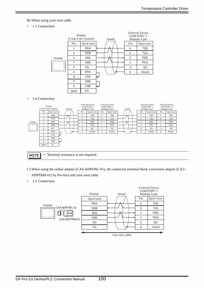
Temperature Controller Driver
GP-Pro EX Device/PLC Connection Manual 100
B) When using your own cable
• 1:1 Connection
• 1:n Connection
C) When using the online adapter (CA4-ADPONL-01), the connector terminal block conversion adapter (CA3-
ADPTRM-01) by Pro-face and your own cable
• 1:1 Connection
• Terminal resistance is not required.
3 SG
4
52
T(B)
T(A)R(B)
1 R(A)
6
SDA3
RDB2
SG5
4 ERA
SDB
ERB
7
9
CSB6
FG
RDA1
CSA8
External DeviceCOM.PORT 1Modular 6 pinShield
Shield
Display
Shell
DisplayD-Sub 9 pin (Socket)
Pin Signal name Pin Signal name
4
52
T(B)
T(A)R(B)
1 R(A)
6
SDA3
RDB2
SG5
4 ERA
SDB
ERB
7
9
CSB6
FG
RDA1
CSA8
4
52
T(B)
T(A)R(B)
1 R(A)
6
4
52
T(B)
T(A)R(B)
1 R(A)
6
4
52
T(B)
T(A)R(B)
1 R(A)
63 SG3 SG 3 SG3 SG
External DeviceCOM.PORT 1Modular 6 pin
External DeviceCOM.PORT 2Modular 6 pin
External DeviceCOM.PORT 1Modular 6 pin
External DeviceCOM.PORT 2Modular 6 pinShield Shield
Shield Shield Shield Shield
Display
Shell
DisplayD-Sub 9 pin (Socket)
Pin Signal name Pin Signal name Pin Signal name Pin Signal name Pin Signal name
RDB
SDBSGFG
CA4-ADPONL-01
CA3-ADPTRM-01
RDA
SDA
4
52
T(B)
T(A)R(B)
1 R(A)
63 SG
Shield
Display
Display
Signal name
External DeviceCOM.PORT 1Modular 6 pin
Shield
Pin Signal name
Your own cable
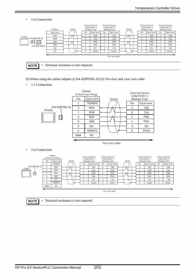
Temperature Controller Driver
GP-Pro EX Device/PLC Connection Manual 101
• 1:n Connection
D) When using the online adapter (CA4-ADPONL-01) by Pro-face and your own cable
• 1:1 Connection
• 1:n Connection
• Terminal resistance is not required.
• Terminal resistance is not required.
RDB
SDBSGFG
CA4-ADPONL-01
CA3-ADPTRM-01
RDA
SDA
4
52
T(B)
T(A)R(B)
1 R(A)
6
4
52
T(B)
T(A)R(B)
1 R(A)
6
4
52
T(B)
T(A)R(B)
1 R(A)
6
4
52
T(B)
T(A)R(B)
1 R(A)
63 SG3 SG3 SG3 SG
Shield Shield
Display
Display
Signal name
External DeviceCOM.PORT 1Modular 6 pin
External DeviceCOM.PORT 2Modular 6 pin
Shield Shield
Pin Signal name Pin Signal name
External DeviceCOM.PORT 1Modular 6 pin
External DeviceCOM.PORT 2Modular 6 pin
Shield Shield
Pin Signal name Pin Signal name
Your own cable
CA4-ADPONL-01 4
52
T(B)
T(A)R(B)
1 R(A)
6
RDB7
RDA2
SDB8
9 TERMTX
SDA
FGShell
3
TERMRX1
SG5 3 SG
Shield
Display
DisplayD-Sub 9 pin (Plug)Pin Signal name
External DeviceCOM.PORT 1Modular 6 pin
Shield
Pin Signal name
Your own cable
CA4-ADPONL-01 4
52
T(B)
T(A)R(B)
1 R(A)
6
RDB7
RDA2
SDB8
9 TERMTX
SDA
FG
3
TERMRX1
SG5
4
52
T(B)
T(A)R(B)
1 R(A)
6
4
52
T(B)
T(A)R(B)
1 R(A)
6
4
52
T(B)
T(A)R(B)
1 R(A)
63 SG3 SG 3 SG3 SG
Shield Shield
Shell
Display
DisplayD-Sub 9 pin (Plug)Pin Signal name
External DeviceCOM.PORT 1Modular 6 pin
External DeviceCOM.PORT 2Modular 6 pin
Shield Shield
Pin Signal name Pin Signal name
External DeviceCOM.PORT 1Modular 6 pin
External DeviceCOM.PORT 2Modular 6 pin
Shield Shield
Pin Signal name Pin Signal name
Your own cable
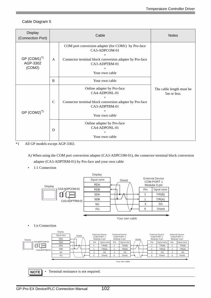
Temperature Controller Driver
GP-Pro EX Device/PLC Connection Manual 102
Cable Diagram 5
A) When using the COM port conversion adapter (CA3-ADPCOM-01), the connector terminal block conversion
adapter (CA3-ADPTRM-01) by Pro-face and your own cable
• 1:1 Connection
• 1:n Connection
Display(Connection Port)
Cable Notes
GP (COM1)*1AGP-3302 (COM2)
*1 All GP models except AGP-3302.
A
COM port conversion adapter (for COM1) by Pro-faceCA3-ADPCOM-01
+Connector terminal block conversion adapter by Pro-face
CA3-ADPTRM-01+
Your own cable
The cable length must be 5m or less.
B Your own cable
GP (COM2)*1
C
Online adapter by Pro-faceCA4-ADPONL-01
+Connector terminal block conversion adapter by Pro-face
CA3-ADPTRM-01+
Your own cable
D
Online adapter by Pro-faceCA4-ADPONL-01
+Your own cable
• Terminal resistance is not required.
RDB
SDBSGFG
CA3-ADPCOM-01
CA3-ADPTRM-01
RDA
SDA 2
1
T/R(B)
T/R(A)
63 SG
Shield
Display
Display
Signal name External DeviceCOM.PORT 1Modular 6 pin
Shield
Pin Signal name
Your own cable
RDB
SDBSGFG
CA3-ADPCOM-01
CA3-ADPTRM-01
RDA
SDA 2
1
T/R(B)
T/R(A)
6
2
1
T/R(B)
T/R(A)
6
2
1
T/R(B)
T/R(A)
6
2
1
T/R(B)
T/R(A)
63 SG 3 SG 3 SG 3 SG
Shield
ShieldDisplay
Display
Signal name External DeviceCOM.PORT 1Modular 6 pin
Shield Shield
Pin Signal name
External DeviceCOM.PORT 2Modular 6 pinPin Signal name
External DeviceCOM.PORT 1Modular 6 pin
Shield Shield
Pin Signal name
External DeviceCOM.PORT 2Modular 6 pinPin Signal name
Your own cable
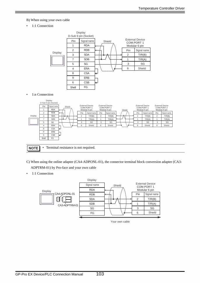
Temperature Controller Driver
GP-Pro EX Device/PLC Connection Manual 103
B) When using your own cable
• 1:1 Connection
• 1:n Connection
C) When using the online adapter (CA4-ADPONL-01), the connector terminal block conversion adapter (CA3-
ADPTRM-01) by Pro-face and your own cable
• 1:1 Connection
• Terminal resistance is not required.
SDA3
RDB2
SG5
4 ERA
SDB
ERB
7
9
CSB6
FGShell
RDA1
CSA8
2
1
T/R(B)
T/R(A)
63 SG
Shield
Display
External DeviceCOM.PORT 1Modular 6 pin
Shield
Pin Signal name
Pin Signal name
DisplayD-Sub 9 pin (Socket)
SDA3
RDB2
SG5
4 ERA
SDB
ERB
7
9
CSB6
FG
RDA1
CSA8
2
1
T/R(B)
T/R(A)
6
2
1
T/R(B)
T/R(A)
6
2
1
T/R(B)
T/R(A)
6
2
1
T/R(B)
T/R(A)
63 SG 3 SG 3 SG 3 SG
Shield
Shield
External DeviceCOM.PORT 1Modular 6 pin
Shield Shield
Pin Signal name
External DeviceCOM.PORT 2Modular 6 pinPin Signal name
External DeviceCOM.PORT 1Modular 6 pin
Shield Shield
Pin Signal name
External DeviceCOM.PORT 2Modular 6 pinPin Signal name
Shell
Display
Pin Signal name
DisplayD-Sub 9 pin (Socket)
RDB
SDBSGFG
CA4-ADPONL-01
CA3-ADPTRM-01
RDA
SDA 2
1
T/R(B)
T/R(A)
63 SG
Shield
Display
Display
Signal name External DeviceCOM.PORT 1Modular 6 pin
Shield
Pin Signal name
Your own cable
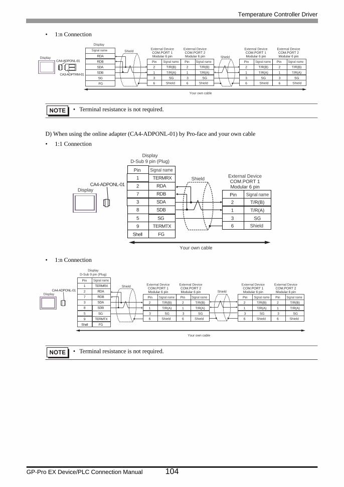
Temperature Controller Driver
GP-Pro EX Device/PLC Connection Manual 104
• 1:n Connection
D) When using the online adapter (CA4-ADPONL-01) by Pro-face and your own cable
• 1:1 Connection
• 1:n Connection
• Terminal resistance is not required.
• Terminal resistance is not required.
RDB
SDBSGFG
CA4-ADPONL-01
CA3-ADPTRM-01
RDA
SDA 2
1
T/R(B)
T/R(A)
6
2
1
T/R(B)
T/R(A)
6
2
1
T/R(B)
T/R(A)
6
2
1
T/R(B)
T/R(A)
63 SG 3 SG 3 SG 3 SG
Shield
ShieldDisplay
Display
Signal name External DeviceCOM.PORT 1Modular 6 pin
Shield Shield
Pin Signal name
External DeviceCOM.PORT 2Modular 6 pinPin Signal name
External DeviceCOM.PORT 1Modular 6 pin
Shield Shield
Pin Signal name
External DeviceCOM.PORT 2Modular 6 pin
Pin Signal name
Your own cable
CA4-ADPONL-01
RDB7
RDA2
SDB8
9 TERMTX
SDA
FG
3
TERMRX1
SG5
2
1
T/R(B)
T/R(A)
63 SG
Your own cable
Shell
Shield
Display
External DeviceCOM.PORT 1Modular 6 pin
Shield
Pin Signal name
Pin Signal name
DisplayD-Sub 9 pin (Plug)
CA4-ADPONL-01
RDB7
RDA2
SDB8
9 TERMTX
SDA
FG
3
TERMRX1
SG5
2
1
T/R(B)
T/R(A)
6
2
1
T/R(B)
T/R(A)
6
2
1
T/R(B)
T/R(A)
6
2
1
T/R(B)
T/R(A)
63 SG 3 SG 3 SG 3 SG
External DeviceCOM.PORT 1Modular 6 pin
Shield Shield
Pin Signal name
External DeviceCOM.PORT 2Modular 6 pinPin Signal name
External DeviceCOM.PORT 1Modular 6 pin
Shield Shield
Pin Signal name
External DeviceCOM.PORT 2Modular 6 pinPin Signal name
Your own cable
Shield
Shell
Shield
Display
Pin Signal name
DisplayD-Sub 9 pin (Plug)
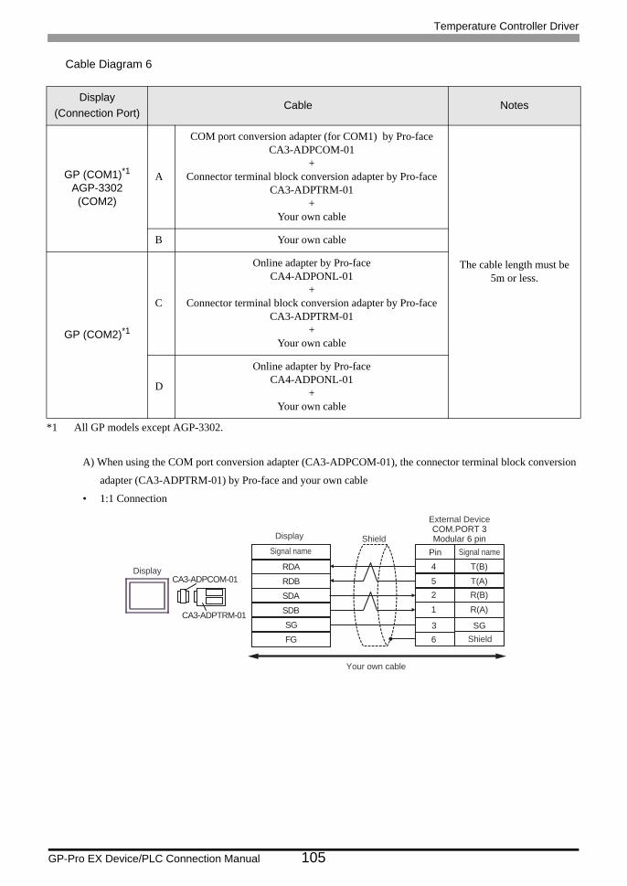
Temperature Controller Driver
GP-Pro EX Device/PLC Connection Manual 105
Cable Diagram 6
A) When using the COM port conversion adapter (CA3-ADPCOM-01), the connector terminal block conversion
adapter (CA3-ADPTRM-01) by Pro-face and your own cable
• 1:1 Connection
Display(Connection Port)
Cable Notes
GP (COM1)*1AGP-3302 (COM2)
*1 All GP models except AGP-3302.
A
COM port conversion adapter (for COM1) by Pro-faceCA3-ADPCOM-01
+Connector terminal block conversion adapter by Pro-face
CA3-ADPTRM-01+
Your own cable
The cable length must be 5m or less.
B Your own cable
GP (COM2)*1
C
Online adapter by Pro-faceCA4-ADPONL-01
+Connector terminal block conversion adapter by Pro-face
CA3-ADPTRM-01+
Your own cable
D
Online adapter by Pro-faceCA4-ADPONL-01
+Your own cable
RDB
SDBSGFG
CA3-ADPCOM-01
CA3-ADPTRM-01
RDA
SDA
4
52
T(B)
T(A)R(B)
1 R(A)
63 SG
Shield
Display
Display
Signal name
External DeviceCOM.PORT 3Modular 6 pin
Shield
Pin Signal name
Your own cable
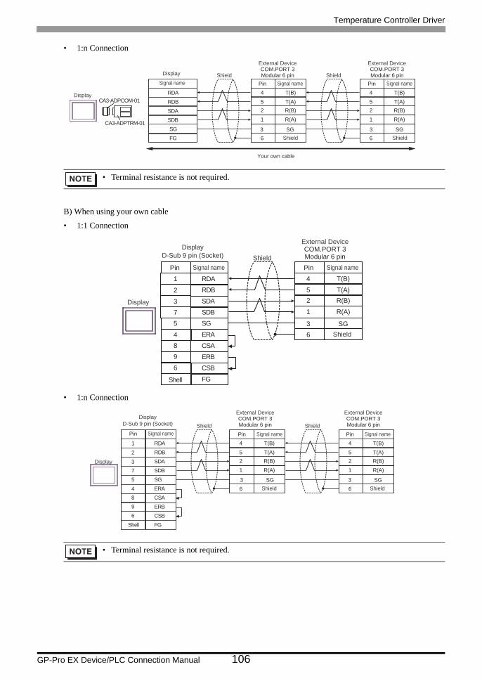
Temperature Controller Driver
GP-Pro EX Device/PLC Connection Manual 106
• 1:n Connection
B) When using your own cable
• 1:1 Connection
• 1:n Connection
• Terminal resistance is not required.
• Terminal resistance is not required.
RDB
SDBSGFG
CA3-ADPCOM-01
CA3-ADPTRM-01
RDA
SDA
4
52
T(B)
T(A)R(B)
1 R(A)
6
4
52
T(B)
T(A)R(B)
1 R(A)
63 SG
Shield
Display
Display
Signal name
External DeviceCOM.PORT 3Modular 6 pin
Shield
Pin Signal name
3 SG
Shield
External DeviceCOM.PORT 3Modular 6 pin
Shield
Pin Signal name
Your own cable
4
52
T(B)
T(A)R(B)
1 R(A)
6
SDA3
RDB2
SG5
4 ERA
SDB
ERB
7
9
CSB6
FG
RDA1
CSA8
3 SG
Shell
Shield
Display
External DeviceCOM.PORT 3Modular 6 pin
Shield
Pin Signal namePin Signal name
DisplayD-Sub 9 pin (Socket)
4
52
T(B)
T(A)R(B)
1 R(A)
6
SDA3
RDB2
SG5
4 ERA
SDB
ERB
7
9
CSB6
FG
RDA1
CSA8
4
52
T(B)
T(A)R(B)
1 R(A)
63 SG
Shell
Shield
Display
External DeviceCOM.PORT 3Modular 6 pin
Shield
Pin Signal name
3 SG
Shield
External DeviceCOM.PORT 3Modular 6 pin
Shield
Pin Signal namePin Signal name
DisplayD-Sub 9 pin (Socket)
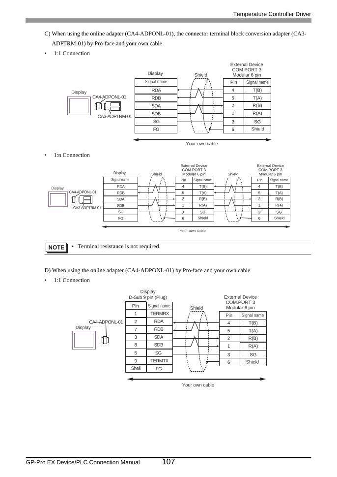
Temperature Controller Driver
GP-Pro EX Device/PLC Connection Manual 107
C) When using the online adapter (CA4-ADPONL-01), the connector terminal block conversion adapter (CA3-
ADPTRM-01) by Pro-face and your own cable
• 1:1 Connection
• 1:n Connection
D) When using the online adapter (CA4-ADPONL-01) by Pro-face and your own cable
• 1:1 Connection
• Terminal resistance is not required.
RDB
SDBSGFG
CA4-ADPONL-01
CA3-ADPTRM-01
RDA
SDA
4
52
T(B)
T(A)R(B)
1 R(A)
63 SG
Shield
Display
Display
Signal name
External DeviceCOM.PORT 3Modular 6 pin
Shield
Pin Signal name
Your own cable
RDB
SDBSGFG
CA4-ADPONL-01
CA3-ADPTRM-01
RDA
SDA
4
52
T(B)
T(A)R(B)
1 R(A)
6
4
52
T(B)
T(A)R(B)
1 R(A)
63 SG
Shield
Display
Display
Signal name
External DeviceCOM.PORT 3Modular 6 pin
Shield
Pin Signal name
3 SG
Shield
External DeviceCOM.PORT 3Modular 6 pin
Shield
Pin Signal name
Your own cable
CA4-ADPONL-01RDB7
RDA2
SDB8
9 TERMTX
SDA
FG
3
TERMRX1
SG5
4
52
T(B)
T(A)R(B)
1 R(A)
6
Your own cable
3 SG
Shell
Shield
Display
External DeviceCOM.PORT 3Modular 6 pin
Shield
Pin Signal name
Pin Signal name
DisplayD-Sub 9 pin (Plug)
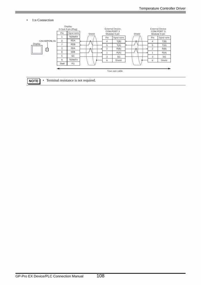
Temperature Controller Driver
GP-Pro EX Device/PLC Connection Manual 108
• 1:n Connection
• Terminal resistance is not required.
CA4-ADPONL-01RDB7
RDA2
SDB8
9 TERMTX
SDA
FG
3
TERMRX1
SG5
4
52
T(B)
T(A)R(B)
1 R(A)
6
4
52
T(B)
T(A)R(B)
1 R(A)
6
Your own cable
Shield Shield
3 SG
External DeviceCOM.PORT 3Modular 6 pin
Shield
Pin Signal name
3 SG
External DeviceCOM.PORT 3Modular 6 pin
Shield
Pin Signal name
Shell
Display
Pin Signal name
DisplayD-Sub 9 pin (Plug)
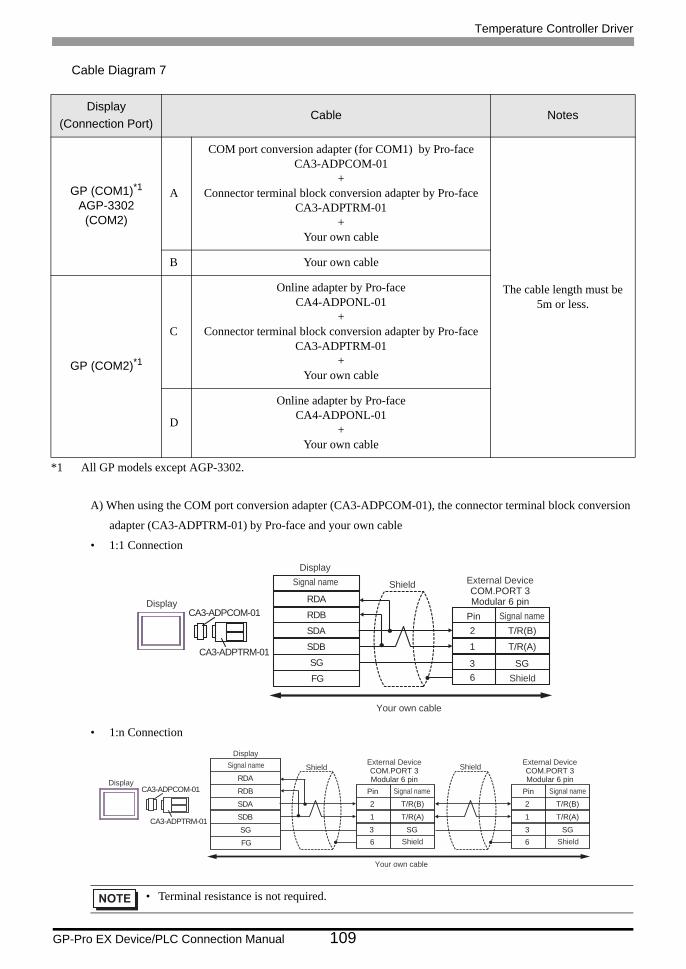
Temperature Controller Driver
GP-Pro EX Device/PLC Connection Manual 109
Cable Diagram 7
A) When using the COM port conversion adapter (CA3-ADPCOM-01), the connector terminal block conversion
adapter (CA3-ADPTRM-01) by Pro-face and your own cable
• 1:1 Connection
• 1:n Connection
Display(Connection Port)
Cable Notes
GP (COM1)*1AGP-3302 (COM2)
*1 All GP models except AGP-3302.
A
COM port conversion adapter (for COM1) by Pro-faceCA3-ADPCOM-01
+Connector terminal block conversion adapter by Pro-face
CA3-ADPTRM-01+
Your own cable
The cable length must be 5m or less.
B Your own cable
GP (COM2)*1
C
Online adapter by Pro-faceCA4-ADPONL-01
+Connector terminal block conversion adapter by Pro-face
CA3-ADPTRM-01+
Your own cable
D
Online adapter by Pro-faceCA4-ADPONL-01
+Your own cable
• Terminal resistance is not required.
RDB
SDBSGFG
CA3-ADPCOM-01
CA3-ADPTRM-01
RDA
SDA 2
1
T/R(B)
T/R(A)
63 SG
Shield
Display
DisplaySignal name External Device
COM.PORT 3Modular 6 pin
Shield
Pin Signal name
Your own cable
RDB
SDBSGFG
CA3-ADPCOM-01
CA3-ADPTRM-01
RDA
SDA 2
1
T/R(B)
T/R(A)
6
2
1
T/R(B)
T/R(A)
6
Shield
Display
DisplaySignal name
3 SG
External DeviceCOM.PORT 3Modular 6 pin
Shield
Pin Signal name
3 SG
External DeviceCOM.PORT 3Modular 6 pin
Shield
Pin Signal name
Your own cable
Shield
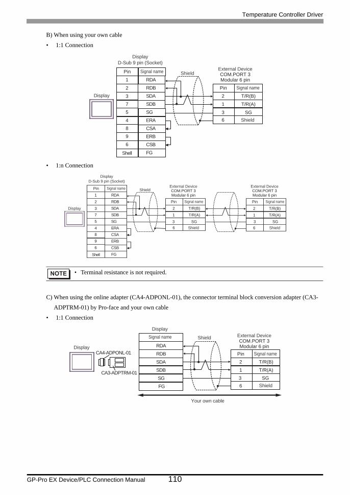
Temperature Controller Driver
GP-Pro EX Device/PLC Connection Manual 110
B) When using your own cable
• 1:1 Connection
• 1:n Connection
C) When using the online adapter (CA4-ADPONL-01), the connector terminal block conversion adapter (CA3-
ADPTRM-01) by Pro-face and your own cable
• 1:1 Connection
• Terminal resistance is not required.
SDA3
RDB2
SG5
4 ERA
SDB
ERB
7
9
CSB6
FG
RDA1
CSA8
2
1
T/R(B)
T/R(A)
63 SG
Shell
Shield
Display
External DeviceCOM.PORT 3Modular 6 pin
Shield
Pin Signal name
Pin Signal name
DisplayD-Sub 9 pin (Socket)
SDA3
RDB2
SG5
4 ERA
SDB
ERB
7
9
CSB6
FG
RDA1
CSA8
2
1
T/R(B)
T/R(A)
6
2
1
T/R(B)
T/R(A)
6
Display
3 SG
External DeviceCOM.PORT 3Modular 6 pin
Shield
Pin Signal name
3 SG
External DeviceCOM.PORT 3Modular 6 pin
Shield
Pin Signal name
Shell
ShieldPin Signal name
DisplayD-Sub 9 pin (Socket)
RDB
SDBSGFG
CA4-ADPONL-01
CA3-ADPTRM-01
RDA
SDA 2
1
T/R(B)
T/R(A)
63 SG
Shield
Display
DisplaySignal name External Device
COM.PORT 3Modular 6 pin
Shield
Pin Signal name
Your own cable
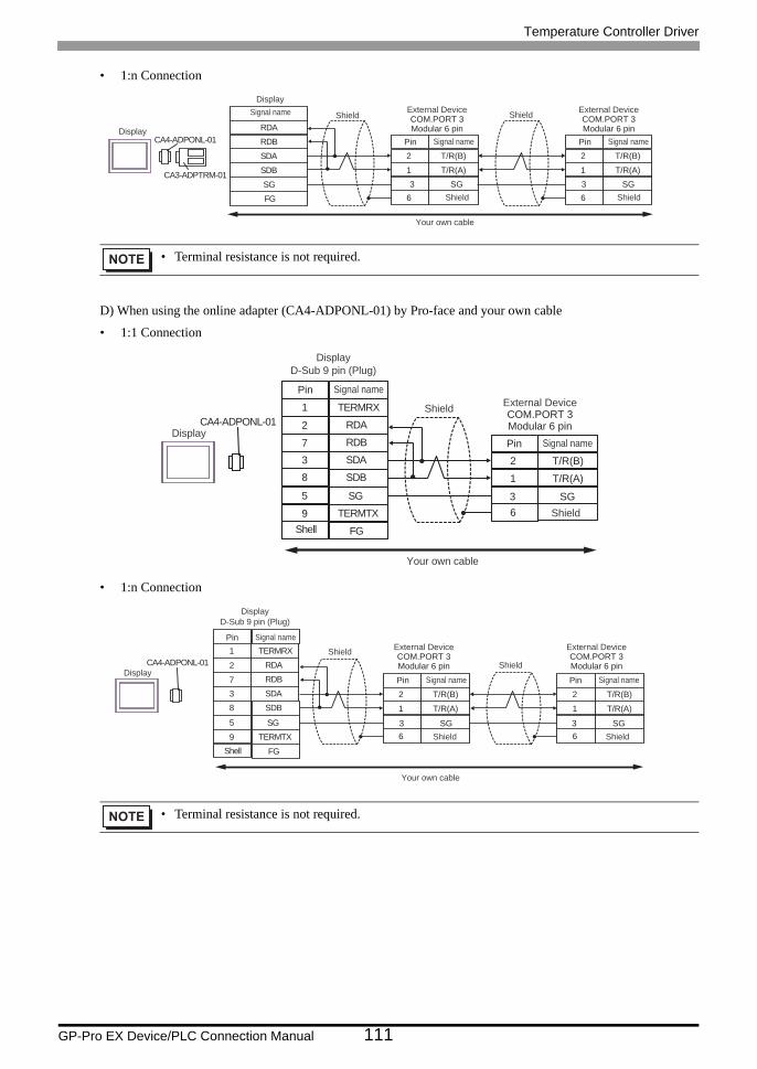
Temperature Controller Driver
GP-Pro EX Device/PLC Connection Manual 111
• 1:n Connection
D) When using the online adapter (CA4-ADPONL-01) by Pro-face and your own cable
• 1:1 Connection
• 1:n Connection
• Terminal resistance is not required.
• Terminal resistance is not required.
RDB
SDBSGFG
CA4-ADPONL-01
CA3-ADPTRM-01
RDA
SDA 2
1
T/R(B)
T/R(A)
6
2
1
T/R(B)
T/R(A)
6
Shield
Display
DisplaySignal name
3 SG
External DeviceCOM.PORT 3Modular 6 pin
Shield
Pin Signal name
3 SG
External DeviceCOM.PORT 3Modular 6 pin
Shield
Pin Signal name
Your own cable
Shield
CA4-ADPONL-01
RDB7
RDA2
SDB8
9 TERMTX
SDA
FG
3
TERMRX1
SG5
2
1
T/R(B)
T/R(A)
6
Your own cable
3 SG
Shell
Shield
Display
External DeviceCOM.PORT 3Modular 6 pin
Shield
Pin Signal name
Pin Signal name
DisplayD-Sub 9 pin (Plug)
CA4-ADPONL-01
RDB7
RDA2
SDB8
9 TERMTX
SDA
FG
3
TERMRX1
SG5
2
1
T/R(B)
T/R(A)
6
2
1
T/R(B)
T/R(A)
6
Your own cable
ShieldShield
3 SG
External DeviceCOM.PORT 3Modular 6 pin
Shield
Pin Signal name
3 SG
External DeviceCOM.PORT 3Modular 6 pin
Shield
Pin Signal name
Shell
Display
Pin Signal name
DisplayD-Sub 9 pin (Plug)
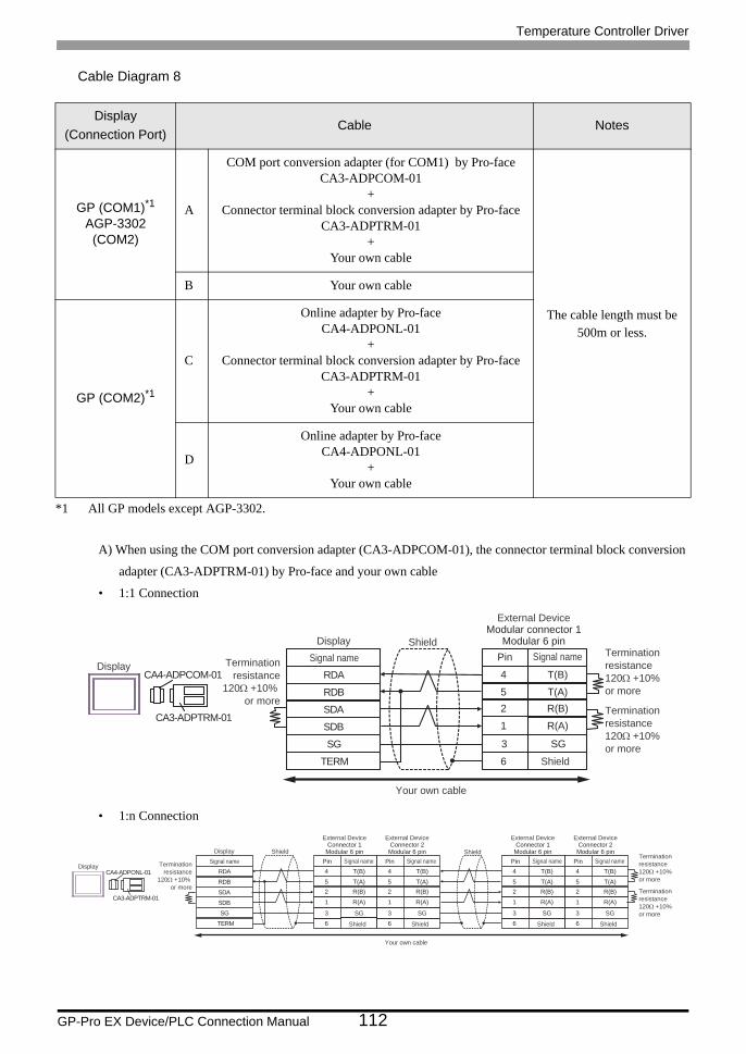
Temperature Controller Driver
GP-Pro EX Device/PLC Connection Manual 112
Cable Diagram 8
A) When using the COM port conversion adapter (CA3-ADPCOM-01), the connector terminal block conversion
adapter (CA3-ADPTRM-01) by Pro-face and your own cable
• 1:1 Connection
• 1:n Connection
Display(Connection Port)
Cable Notes
GP (COM1)*1AGP-3302 (COM2)
*1 All GP models except AGP-3302.
A
COM port conversion adapter (for COM1) by Pro-faceCA3-ADPCOM-01
+Connector terminal block conversion adapter by Pro-face
CA3-ADPTRM-01+
Your own cable
The cable length must be 500m or less.
B Your own cable
GP (COM2)*1
C
Online adapter by Pro-faceCA4-ADPONL-01
+Connector terminal block conversion adapter by Pro-face
CA3-ADPTRM-01+
Your own cable
D
Online adapter by Pro-faceCA4-ADPONL-01
+Your own cable
RDB
SDBSG
TERM
CA4-ADPCOM-01
CA3-ADPTRM-01
RDA
SDA
4
52
T(B)
T(A)R(B)
1 R(A)
6
3 SG
Shield
Display
DisplaySignal name
External DeviceModular connector 1
Modular 6 pin
Shield
Pin Signal name
Your own cable
Terminationresistance
120Ω +10% or more
Terminationresistance120Ω +10% or more
Terminationresistance120Ω +10% or more
RDB
SDBSG
TERM
CA4-ADPONL-01
CA3-ADPTRM-01
RDA
SDA
4
52
T(B)
T(A)R(B)
1 R(A)
3 SG6
4
52
T(B)
T(A)R(B)
1 R(A)
3 SG6
4
52
T(B)
T(A)R(B)
1 R(A)
3 SG 3 SG6
4
52
T(B)
T(A)R(B)
1 R(A)
6
ShieldShield
External DeviceConnector 1
Modular 6 pin
Shield
Pin Signal name
External DeviceConnector 2
Modular 6 pin
Shield
Pin Signal name
External DeviceConnector 1
Modular 6 pin
Shield
Pin Signal name
External DeviceConnector 2
Modular 6 pin
Shield
Pin Signal name
Your own cable
Terminationresistance120Ω +10% or more
Display
DisplaySignal nameTermination
resistance120Ω +10%
or more Terminationresistance120Ω +10% or more
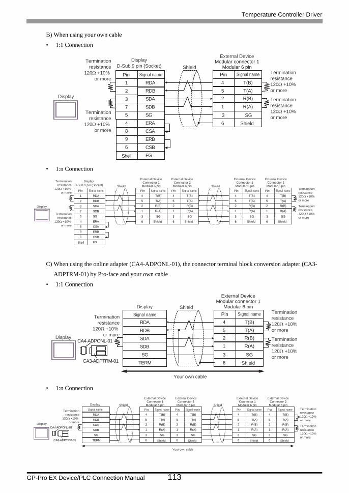
Temperature Controller Driver
GP-Pro EX Device/PLC Connection Manual 113
B) When using your own cable
• 1:1 Connection
• 1:n Connection
C) When using the online adapter (CA4-ADPONL-01), the connector terminal block conversion adapter (CA3-
ADPTRM-01) by Pro-face and your own cable
• 1:1 Connection
• 1:n Connection
4
52
T(B)
T(A)R(B)
1 R(A)
6
SDA3
RDB2
SG5
4 ERA
SDB
ERB
7
9
CSB6
FG
RDA1
CSA8
Terminationresistance
120Ω +10% or more
Terminationresistance
120Ω +10% or more
3 SG
External DeviceModular connector 1
Modular 6 pin
Shield
Pin Signal name Terminationresistance120Ω +10% or more
Terminationresistance120Ω +10% or more
Shell
Shield
Display
Pin Signal name
DisplayD-Sub 9 pin (Socket)
4
52
T(B)
T(A)R(B)
1 R(A)
3 SG6
SDA3
RDB2
SG5
4 ERA
SDB
ERB
7
9
CSB6
FG
RDA1
CSA8
4
52
T(B)
T(A)R(B)
1 R(A)
3 SG6
4
52
T(B)
T(A)R(B)
1 R(A)
3 SG 3 SG6
4
52
T(B)
T(A)R(B)
1 R(A)
6
External DeviceConnector 1
Modular 6 pin
Shield
Pin Signal name
External DeviceConnector 2
Modular 6 pin
Shield
Pin Signal name
External DeviceConnector 1
Modular 6 pin
Shield
Pin Signal name
External DeviceConnector 2
Modular 6 pin
Shield
Pin Signal name
Terminationresistance
120Ω +10% or more
Terminationresistance
120Ω +10% or more
Terminationresistance120Ω +10% or more
Terminationresistance120Ω +10% or more
Shield Shield
Display
Shell
Pin Signal name
DisplayD-Sub 9 pin (Socket)
RDB
SDBSG
TERM
CA4-ADPONL-01
CA3-ADPTRM-01
RDA
SDA
4
52
T(B)
T(A)R(B)
1 R(A)
3 SG6
Shield
Display
DisplaySignal name
External DeviceModular connector 1
Modular 6 pin
Shield
Pin Signal name
Your own cable
Terminationresistance
120Ω +10% or more
Terminationresistance120Ω +10% or more
Terminationresistance120Ω +10% or more
RDB
SDBSG
TERM
CA4-ADPONL-01
CA3-ADPTRM-01
RDA
SDA
4
52
T(B)
T(A)R(B)
1 R(A)
3 SG6
4
52
T(B)
T(A)R(B)
1 R(A)
3 SG6
4
52
T(B)
T(A)R(B)
1 R(A)
3 SG6
4
52
T(B)
T(A)R(B)
1 R(A)
3 SG6
Your own cable
Display
DisplaySignal nameTermination
resistance120Ω +10%
or more
Terminationresistance120Ω +10% or more
Terminationresistance120Ω +10% or more
Shield
External DeviceConnector 1
Modular 6 pin
Shield
Pin Signal name
External DeviceConnector 2
Modular 6 pin
Shield
Pin Signal nameShield
External DeviceConnector 1
Modular 6 pin
Shield
Pin Signal name
External DeviceConnector 2
Modular 6 pin
Shield
Pin Signal name
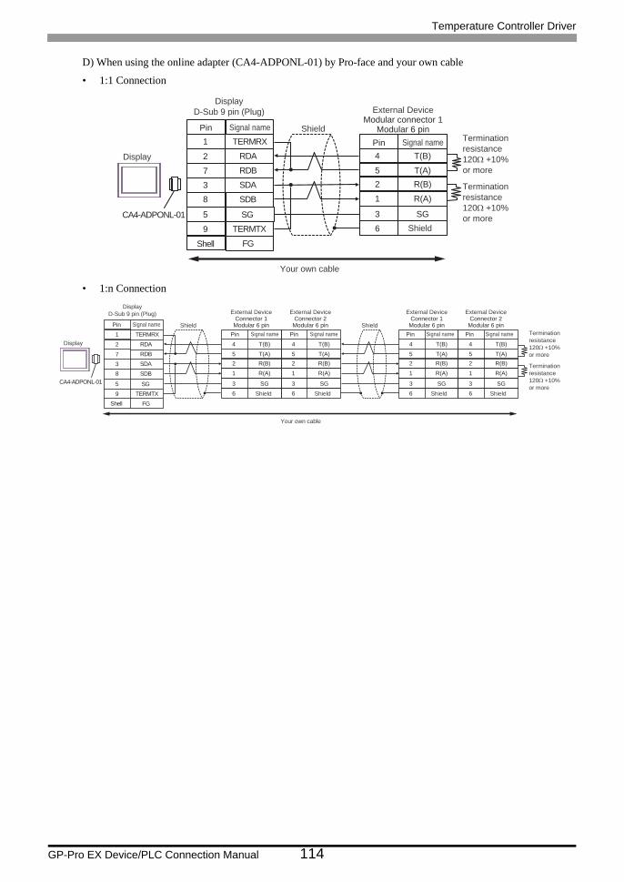
Temperature Controller Driver
GP-Pro EX Device/PLC Connection Manual 114
D) When using the online adapter (CA4-ADPONL-01) by Pro-face and your own cable
• 1:1 Connection
• 1:n Connection
CA4-ADPONL-01
4
52
T(B)
T(A)R(B)
1 R(A)
3 SG6
RDB7
RDA2
SDB8
9 TERMTX
SDA
FG
3
TERMRX1
SG5
Your own cable
External DeviceModular connector 1
Modular 6 pin
Shield
Pin Signal name Terminationresistance120Ω +10% or more
Terminationresistance120Ω +10% or more
Shell
Shield
Display
Pin Signal name
DisplayD-Sub 9 pin (Plug)
4
52
T(B)
T(A)R(B)
1 R(A)
3 SG6
RDB7
RDA2
SDB8
9 TERMTX
SDA
FG
3
TERMRX1
SG5
4
52
T(B)
T(A)R(B)
1 R(A)
3 SG6
4
52
T(B)
T(A)R(B)
1 R(A)
3 SG6
4
52
T(B)
T(A)R(B)
1 R(A)
3 SG6
CA4-ADPONL-01
Your own cable
External DeviceConnector 1
Modular 6 pin
Shield
Pin Signal name
External DeviceConnector 2
Modular 6 pin
Shield
Pin Signal name
External DeviceConnector 1
Modular 6 pin
Shield
Pin Signal name
External DeviceConnector 2
Modular 6 pin
Shield
Pin Signal name Terminationresistance120Ω +10% or more
Terminationresistance120Ω +10% or more
Shield Shield
Shell
Display
Pin Signal name
DisplayD-Sub 9 pin (Plug)
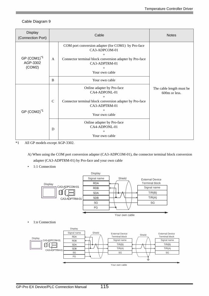
Temperature Controller Driver
GP-Pro EX Device/PLC Connection Manual 115
Cable Diagram 9
A) When using the COM port conversion adapter (CA3-ADPCOM-01), the connector terminal block conversion
adapter (CA3-ADPTRM-01) by Pro-face and your own cable
• 1:1 Connection
• 1:n Connection
Display(Connection Port)
Cable Notes
GP (COM1)*1AGP-3302 (COM2)
*1 All GP models except AGP-3302.
A
COM port conversion adapter (for COM1) by Pro-faceCA3-ADPCOM-01
+Connector terminal block conversion adapter by Pro-face
CA3-ADPTRM-01+
Your own cable
The cable length must be 600m or less.
B Your own cable
GP (COM2)*1
C
Online adapter by Pro-faceCA4-ADPONL-01
+Connector terminal block conversion adapter by Pro-face
CA3-ADPTRM-01+
Your own cable
D
Online adapter by Pro-faceCA4-ADPONL-01
+Your own cable
RDB
SDBSGFG
CA3-ADPCOM-01
CA3-ADPTRM-01
RDA
SDA T/R(B)
T/R(A)
SG
Your own cable
Display
DisplayExternal DeviceTerminal block
ShieldSignal name
Signal name
RDB
SDBSGFG
CA3-ADPCOM-01
CA3-ADPTRM-01
RDA
SDA T/R(B)
T/R(A)
SG
T/R(B)
T/R(A)
SG
Display
Your own cable
Display
External DeviceTerminal block
ShieldSignal name
Signal name
External DeviceTerminal block
Shield
Signal name
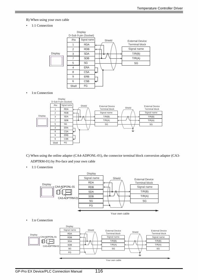
Temperature Controller Driver
GP-Pro EX Device/PLC Connection Manual 116
B) When using your own cable
• 1:1 Connection
• 1:n Connection
C) When using the online adapter (CA4-ADPONL-01), the connector terminal block conversion adapter (CA3-
ADPTRM-01) by Pro-face and your own cable
• 1:1 Connection
• 1:n Connection
SDA3
RDB2
SG5
4 ERA
SDB
ERB
7
9
CSB6
FG
RDA1
CSA8
T/R(B)
T/R(A)
SG
Shell
Pin
DisplayD-Sub 9 pin (Socket)
External DeviceTerminal block
Shield
Signal name
Signal name
Display
SDA3
RDB2
SG5
4 ERA
SDB
ERB
7
9
CSB6
FG
RDA1
CSA8
T/R(B)
T/R(A)
SG
T/R(B)
T/R(A)
SG
Shell
Pin
DisplayD-Sub 9 pin (Socket)
External DeviceTerminal block
ShieldShield
Signal name
External DeviceTerminal blockSignal name
Signal name
Display
RDB
SDBSGFG
CA4-ADPONL-01
CA3-ADPTRM-01
RDA
SDA T/R(B)
T/R(A)
SG
Display
Display
External DeviceTerminal block
ShieldSignal name
Signal name
Your own cable
RDB
SDBSGFG
CA4-ADPONL-01
CA3-ADPTRM-01
RDA
SDA T/R(B)
T/R(A)
SG
T/R(B)
T/R(A)
SG
Your own cable
Display
Display
External DeviceTerminal block
External DeviceTerminal block
ShieldShield
Signal name Signal name
Signal name
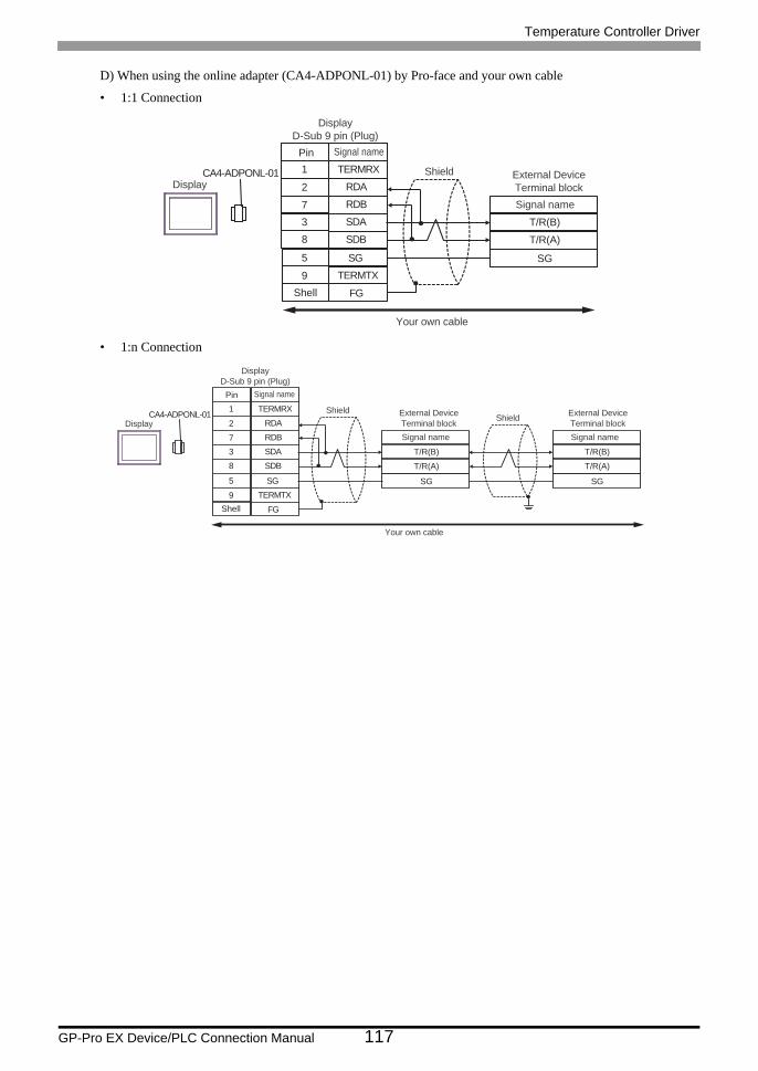
Temperature Controller Driver
GP-Pro EX Device/PLC Connection Manual 117
D) When using the online adapter (CA4-ADPONL-01) by Pro-face and your own cable
• 1:1 Connection
• 1:n Connection
CA4-ADPONL-01
RDB7
RDA2
SDB8
9 TERMTX
SDA
FG
3
TERMRX1
SG5
T/R(B)
T/R(A)
SG
Your own cable
Shell
Pin
DisplayD-Sub 9 pin (Plug)
External DeviceTerminal block
Shield
Signal name
Signal name
Display
CA4-ADPONL-01
RDB7
RDA2
SDB8
9 TERMTX
SDA
FG
3
TERMRX1
SG5
T/R(B)
T/R(A)
SG
T/R(B)
T/R(A)
SG
Your own cable
ShieldShieldExternal Device
Terminal blockSignal name
External DeviceTerminal blockSignal name
Shell
Pin
DisplayD-Sub 9 pin (Plug)
Signal name
Display
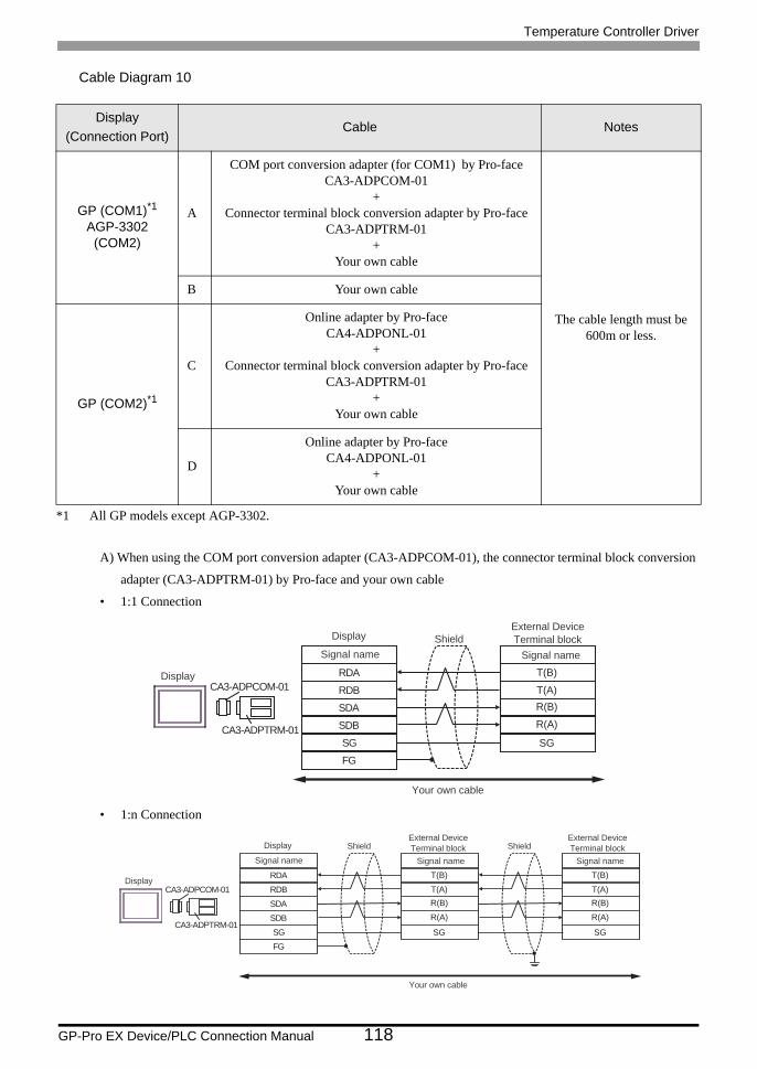
Temperature Controller Driver
GP-Pro EX Device/PLC Connection Manual 118
Cable Diagram 10
A) When using the COM port conversion adapter (CA3-ADPCOM-01), the connector terminal block conversion
adapter (CA3-ADPTRM-01) by Pro-face and your own cable
• 1:1 Connection
• 1:n Connection
Display(Connection Port)
Cable Notes
GP (COM1)*1AGP-3302 (COM2)
*1 All GP models except AGP-3302.
A
COM port conversion adapter (for COM1) by Pro-faceCA3-ADPCOM-01
+Connector terminal block conversion adapter by Pro-face
CA3-ADPTRM-01+
Your own cable
The cable length must be 600m or less.
B Your own cable
GP (COM2)*1
C
Online adapter by Pro-faceCA4-ADPONL-01
+Connector terminal block conversion adapter by Pro-face
CA3-ADPTRM-01+
Your own cable
D
Online adapter by Pro-faceCA4-ADPONL-01
+Your own cable
RDB
SDBSGFG
CA3-ADPCOM-01
CA3-ADPTRM-01
RDA
SDA
T(B)
T(A)R(B)
R(A)
SG
Your own cable
Display
Display
External DeviceTerminal blockShield
Signal name Signal name
RDB
SDBSGFG
CA3-ADPCOM-01
CA3-ADPTRM-01
RDA
SDA
T(B)
T(A)R(B)
R(A)
SG
T(B)
T(A)R(B)
R(A)
SG
Your own cable
Display
Shield ShieldDisplay
Signal name
External DeviceTerminal block
Signal name
External DeviceTerminal block
Signal name
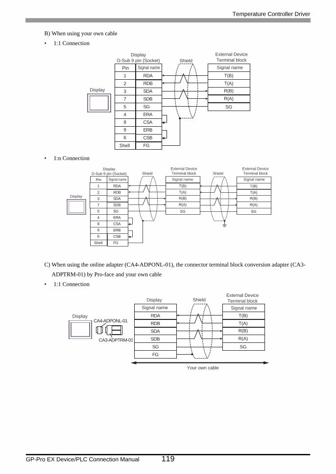
Temperature Controller Driver
GP-Pro EX Device/PLC Connection Manual 119
B) When using your own cable
• 1:1 Connection
• 1:n Connection
C) When using the online adapter (CA4-ADPONL-01), the connector terminal block conversion adapter (CA3-
ADPTRM-01) by Pro-face and your own cable
• 1:1 Connection
SDA3
RDB2
SG5
4 ERA
SDB
ERB
7
9
CSB6
FG
RDA1
CSA8
T(B)
T(A)R(B)
R(A)
SG
Shell
Pin
DisplayD-Sub 9 pin (Socket)
External DeviceTerminal blockShieldSignal nameSignal name
Display
SDA3
RDB2
SG5
4 ERA
SDB
ERB
7
9
CSB6
FG
RDA1
CSA8
T(B)
T(A)R(B)
R(A)
SG
T(B)
T(A)R(B)
R(A)
SG
Shell
Shield ShieldExternal DeviceTerminal blockSignal name
External DeviceTerminal blockSignal namePin
DisplayD-Sub 9 pin (Socket)
Signal name
Display
RDB
SDBSGFG
CA4-ADPONL-01
CA3-ADPTRM-01
RDA
SDA
T(B)
T(A)R(B)
R(A)
SG
Display
Display
External DeviceTerminal blockShield
Signal name Signal name
Your own cable
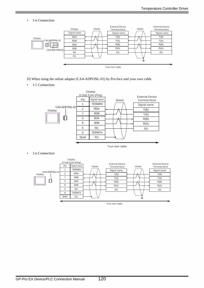
Temperature Controller Driver
GP-Pro EX Device/PLC Connection Manual 120
• 1:n Connection
D) When using the online adapter (CA4-ADPONL-01) by Pro-face and your own cable
• 1:1 Connection
• 1:n Connection
RDB
SDBSGFG
CA4-ADPONL-01
CA3-ADPTRM-01
RDA
SDA
T(B)
T(A)R(B)
R(A)
SG
T(B)
T(A)R(B)
R(A)
SG
Display
DisplayExternal DeviceTerminal blockShield
Signal name Signal name
External DeviceTerminal blockShield
Signal name
Your own cable
CA4-ADPONL-01
RDB7
RDA2
SDB8
9 TERMTX
SDA
FG
3
TERMRX1
SG5
T(B)
T(A)R(B)
R(A)
SG
Your own cable
Shell
Pin
DisplayD-Sub 9 pin (Plug) External Device
Terminal blockShieldSignal name
Signal name
Display
CA4-ADPONL-01
RDB7
RDA2
SDB8
9 TERMTX
SDA
FG
3
TERMRX1
SG5
T(B)
T(A)R(B)
R(A)
SG
T(B)
T(A)R(B)
R(A)
SG
Your own cable
ShieldShieldExternal DeviceTerminal blockSignal name
External DeviceTerminal blockSignal name
Shell
Pin
DisplayD-Sub 9 pin (Plug)
Signal name
Display
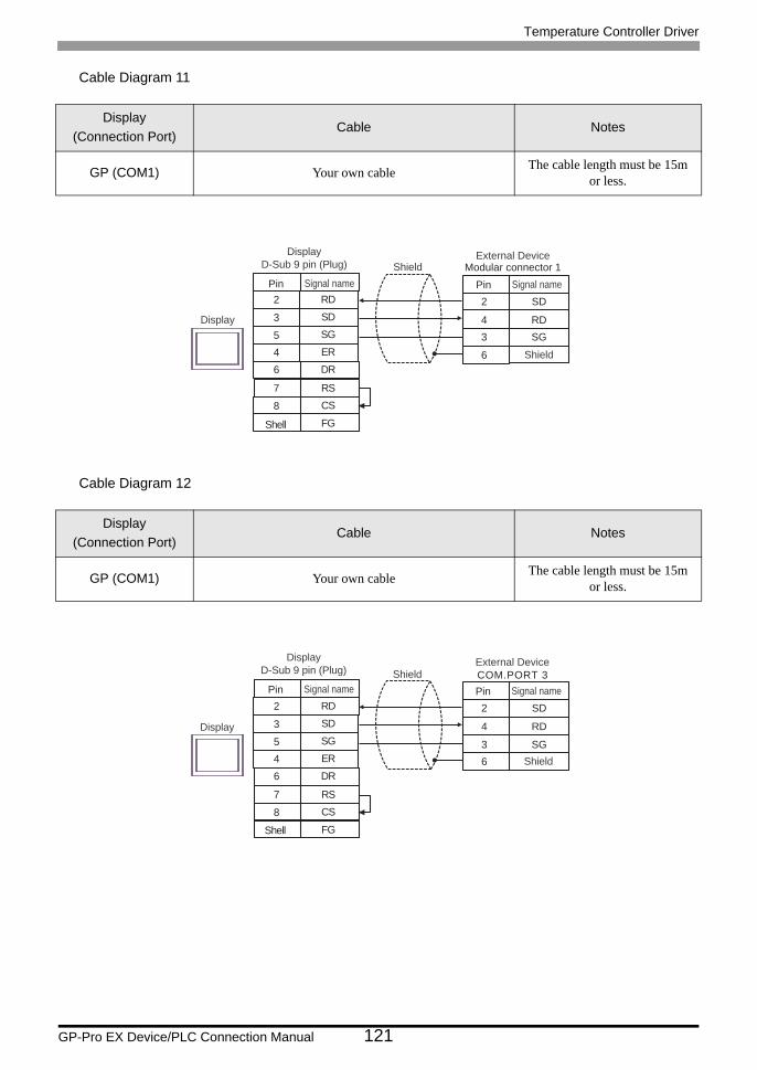
Temperature Controller Driver
GP-Pro EX Device/PLC Connection Manual 121
Cable Diagram 11
Cable Diagram 12
Display(Connection Port)
Cable Notes
GP (COM1) Your own cable The cable length must be 15m or less.
Display(Connection Port)
Cable Notes
GP (COM1) Your own cable The cable length must be 15m or less.
SG5
SD3
DR6
8 CS
ER
FG
4
RD2
RS7
2
4
SD
RD3 SG
6
External DeviceModular connector 1
Shield
Pin Signal name
Shell
Shield
Display
Pin Signal name
DisplayD-Sub 9 pin (Plug)
SG5
SD3
DR6
8 CS
ER
FG
4
RD2
RS7
2
4
SD
RD
3 SG6
External DeviceCOM.PORT 3
Shield
Pin Signal nameShield
Display
Shell
Pin Signal name
DisplayD-Sub 9 pin (Plug)
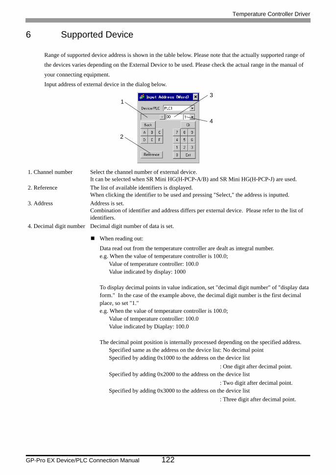
Temperature Controller Driver
GP-Pro EX Device/PLC Connection Manual 122
6 Supported Device
Range of supported device address is shown in the table below. Please note that the actually supported range of
the devices varies depending on the External Device to be used. Please check the actual range in the manual of
your connecting equipment.
Input address of external device in the dialog below.
When reading out:
Data read out from the temperature controller are dealt as integral number.e.g. When the value of temperature controller is 100.0;
Value of temperature controller: 100.0Value indicated by display: 1000
To display decimal points in value indication, set "decimal digit number" of "display data form." In the case of the example above, the decimal digit number is the first decimal place, so set "1."e.g. When the value of temperature controller is 100.0;
Value of temperature controller: 100.0Value indicated by Diaplay: 100.0
The decimal point position is internally processed depending on the specified address.Specified same as the address on the device list: No decimal pointSpecified by adding 0x1000 to the address on the device list
: One digit after decimal point.Specified by adding 0x2000 to the address on the device list
: Two digit after decimal point.Specified by adding 0x3000 to the address on the device list
: Three digit after decimal point.
1. Channel number Select the channel number of external device.It can be selected when SR Mini HG(H-PCP-A/B) and SR Mini HG(H-PCP-J) are used.
2. Reference The list of available identifiers is displayed.When clicking the identifier to be used and pressing "Select," the address is inputted.
3. Address Address is set.Combination of identifier and address differs per external device. Please refer to the list of identifiers.
4. Decimal digit number Decimal digit number of data is set.
1
2
3
4
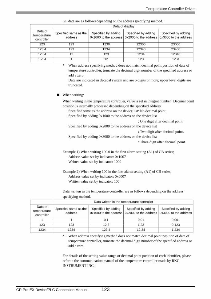
Temperature Controller Driver
GP-Pro EX Device/PLC Connection Manual 123
GP data are as follows depending on the address specifying method.
* When address specifying method does not match decimal point position of data of temperature controller, truncate the decimal digit number of the specified address or add a zero. Data are indicated in decadal system and are 6 digits or more, upper level digits are truncated.
When writing:
When writing in the temperature controller, value is set in integral number. Decimal point position is internally processed depending on the specified address.
Specified same as the address on the device list: No decimal pointSpecified by adding 0x1000 to the address on the device list
: One digit after decimal point.Specified by adding 0x2000 to the address on the device list
: Two digit after decimal point.Specified by adding 0x3000 to the address on the device list
: Three digit after decimal point.
Example 1) When writing 100.0 in the first alarm setting (A1) of CB series;Address value set by indicator: 0x1007Written value set by indicator: 1000
Example 2) When writing 100 in the first alarm setting (A1) of CB series;Address value set by indicator: 0x0007Written value set by indicator: 100
Data written in the temperature controller are as follows depending on the address specifying method.
* When address specifying method does not match decimal point position of data of temperature controller, truncate the decimal digit number of the specified address or add a zero.
For details of the setting value range or decimal point position of each identifier, please refer to the communication manual of the temperature controller made by RKC INSTRUMENT INC.
Data of displayData of
temperature controller
Specified same as the address
Specified by adding 0x1000 to the address
Specified by adding 0x2000 to the address
Specified by adding 0x3000 to the address
123 123 1230 12300 23000123.4 123 1234 12340 2340012.34 12 123 1234 123401.234 1 12 123 1234
Data written in the temperature controllerData of
temperature controller
Specified same as the address
Specified by adding 0x1000 to the address
Specified by adding 0x2000 to the address
Specified by adding 0x3000 to the address
1 1 0.1 0.01 0.001123 123 12.3 1.23 0.123
1234 1234 123.4 12.34 1.234
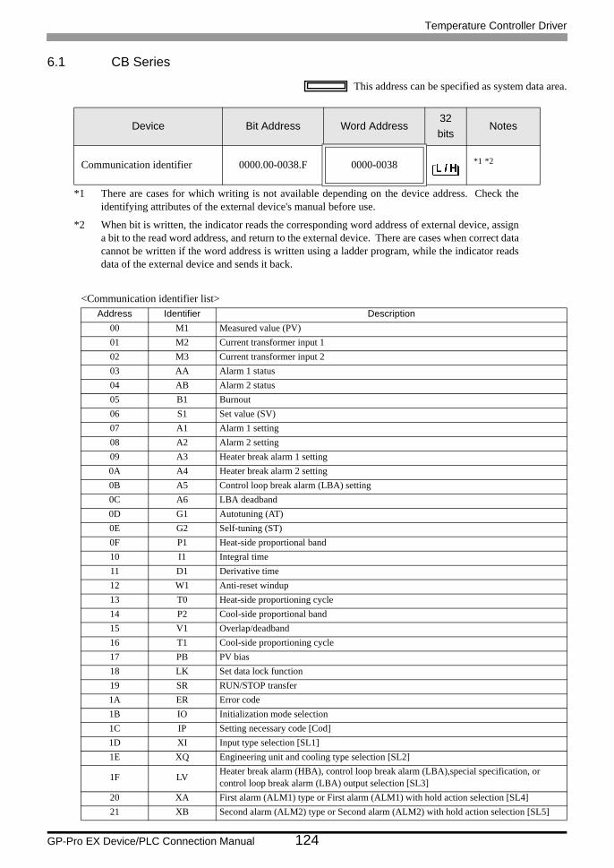
Temperature Controller Driver
GP-Pro EX Device/PLC Connection Manual 124
6.1 CB Series
This address can be specified as system data area.
<Communication identifier list>
Device Bit Address Word Address32bits
Notes
Communication identifier 0000.00-0038.F 0000-0038 *1 *2
*1 There are cases for which writing is not available depending on the device address. Check the identifying attributes of the external device's manual before use.
*2 When bit is written, the indicator reads the corresponding word address of external device, assign a bit to the read word address, and return to the external device. There are cases when correct data cannot be written if the word address is written using a ladder program, while the indicator reads data of the external device and sends it back.
Address Identifier Description00 M1 Measured value (PV)01 M2 Current transformer input 102 M3 Current transformer input 203 AA Alarm 1 status04 AB Alarm 2 status05 B1 Burnout06 S1 Set value (SV)07 A1 Alarm 1 setting08 A2 Alarm 2 setting09 A3 Heater break alarm 1 setting0A A4 Heater break alarm 2 setting0B A5 Control loop break alarm (LBA) setting0C A6 LBA deadband0D G1 Autotuning (AT)0E G2 Self-tuning (ST)0F P1 Heat-side proportional band10 I1 Integral time11 D1 Derivative time12 W1 Anti-reset windup13 T0 Heat-side proportioning cycle14 P2 Cool-side proportional band15 V1 Overlap/deadband16 T1 Cool-side proportioning cycle17 PB PV bias18 LK Set data lock function19 SR RUN/STOP transfer1A ER Error code1B IO Initialization mode selection1C IP Setting necessary code [Cod]1D XI Input type selection [SL1]1E XQ Engineering unit and cooling type selection [SL2]
1F LV Heater break alarm (HBA), control loop break alarm (LBA),special specification, or control loop break alarm (LBA) output selection [SL3]
20 XA First alarm (ALM1) type or First alarm (ALM1) with hold action selection [SL4]21 XB Second alarm (ALM2) type or Second alarm (ALM2) with hold action selection [SL5]
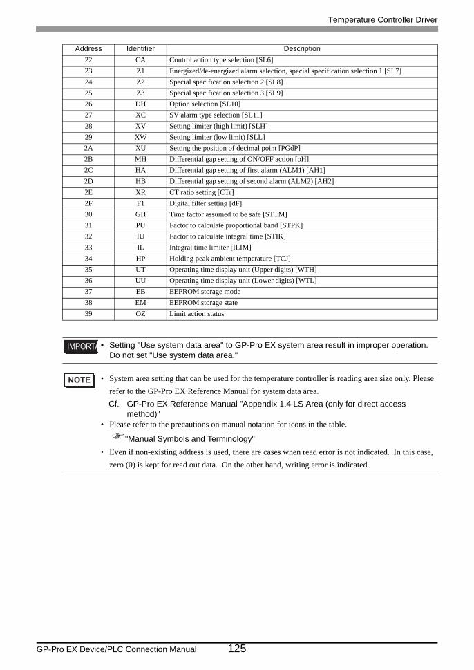
Temperature Controller Driver
GP-Pro EX Device/PLC Connection Manual 125
22 CA Control action type selection [SL6]23 Z1 Energized/de-energized alarm selection, special specification selection 1 [SL7]24 Z2 Special specification selection 2 [SL8]25 Z3 Special specification selection 3 [SL9]26 DH Option selection [SL10]27 XC SV alarm type selection [SL11]28 XV Setting limiter (high limit) [SLH]29 XW Setting limiter (low limit) [SLL]2A XU Setting the position of decimal point [PGdP]2B MH Differential gap setting of ON/OFF action [oH]2C HA Differential gap setting of first alarm (ALM1) [AH1]2D HB Differential gap setting of second alarm (ALM2) [AH2]2E XR CT ratio setting [CTr]2F F1 Digital filter setting [dF]30 GH Time factor assumed to be safe [STTM]31 PU Factor to calculate proportional band [STPK]32 IU Factor to calculate integral time [STIK]33 IL Integral time limiter [ILIM]34 HP Holding peak ambient temperature [TCJ]35 UT Operating time display unit (Upper digits) [WTH]36 UU Operating time display unit (Lower digits) [WTL]37 EB EEPROM storage mode38 EM EEPROM storage state39 OZ Limit action status
• Setting "Use system data area" to GP-Pro EX system area result in improper operation. Do not set "Use system data area."
• System area setting that can be used for the temperature controller is reading area size only. Please refer to the GP-Pro EX Reference Manual for system data area.Cf. GP-Pro EX Reference Manual "Appendix 1.4 LS Area (only for direct access
method)"• Please refer to the precautions on manual notation for icons in the table.
"Manual Symbols and Terminology"• Even if non-existing address is used, there are cases when read error is not indicated. In this case,
zero (0) is kept for read out data. On the other hand, writing error is indicated.
Address Identifier Description
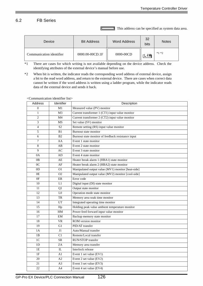
Temperature Controller Driver
GP-Pro EX Device/PLC Connection Manual 126
6.2 FB Series
This address can be specified as system data area.
<Communication identifier list>
Device Bit Address Word Address32bits
Notes
Communication identifier 0000.00-00CD.1F 0000-00CD *1 *2
*1 There are cases for which writing is not available depending on the device address. Check the identifying attributes of the external device’s manual before use.
*2 When bit is written, the indicator reads the corresponding word address of external device, assign a bit to the read word address, and return to the external device. There are cases when correct data cannot be written if the word address is written using a ladder program, while the indicator reads data of the external device and sends it back.
Address Identifier Description0 M1 Measured value (PV) monitor1 M3 Current transformer 1 (CT1) input value monitor2 M4 Current transformer 2 (CT2) input value monitor3 MS Set value (SV) monitor4 S2 Remote setting (RS) input value monitor5 B1 Burnout state monitor6 B2 Burnout state monitor of feedback resistance input7 AA Event 1 state monitor8 AB Event 2 state monitor9 AC Event 3 state monitor
0A AD Event 4 state monitor0B AE Heater break alarm 1 (HBA1) state monitor0C AF Heater break alarm 2 (HBA2) state monitor0D O1 Manipulated output value (MV1) monitor [heat-side]0E O2 Manipulated output value (MV2) monitor [cool-side]0F ER Error code10 L1 Digital input (DI) state monitor11 Q1 Output state monitor12 L0 Operation mode state monitor13 TR Memory area soak time monitor14 UT Integrated operating time monitor15 Hp Holding peak value ambient temperature monitor16 HM Power feed forward input value monitor17 EM Backup memory state monitor18 VR ROM version monitor19 G1 PID/AT transfer1A J1 Auto/Manual transfer1B C1 Remote/Local transfer1C SR RUN/STOP transfer1D ZA Memory area transfer1E IL Interlock release1F A1 Event 1 set value (EV1)20 A2 Event 2 set value (EV2)21 A3 Event 3 set value (EV3)22 A4 Event 4 set value (EV4)
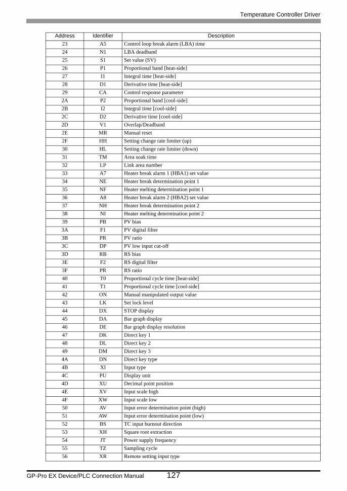
Temperature Controller Driver
GP-Pro EX Device/PLC Connection Manual 127
23 A5 Control loop break alarm (LBA) time24 N1 LBA deadband25 S1 Set value (SV)26 P1 Proportional band [heat-side]27 I1 Integral time [heat-side]28 D1 Derivative time [heat-side]29 CA Control response parameter2A P2 Proportional band [cool-side]2B I2 Integral time [cool-side]2C D2 Derivative time [cool-side]2D V1 Overlap/Deadband2E MR Manual reset2F HH Setting change rate limiter (up)30 HL Setting change rate limiter (down)31 TM Area soak time32 LP Link area number33 A7 Heater break alarm 1 (HBA1) set value34 NE Heater break determination point 135 NF Heater melting determination point 136 A8 Heater break alarm 2 (HBA2) set value37 NH Heater break determination point 238 NI Heater melting determination point 239 PB PV bias3A F1 PV digital filter3B PR PV ratio3C DP PV low input cut-off3D RB RS bias3E F2 RS digital filter3F PR RS ratio40 T0 Proportional cycle time [heat-side]41 T1 Proportional cycle time [cool-side]42 ON Manual manipulated output value43 LK Set lock level44 DX STOP display45 DA Bar graph display46 DE Bar graph display resolution47 DK Direct key 148 DL Direct key 249 DM Direct key 34A DN Direct key type4B XI Input type4C PU Display unit4D XU Decimal point position4E XV Input scale high4F XW Input scale low50 AV Input error determination point (high)51 AW Input error determination point (low)52 BS TC input burnout direction53 XH Square root extraction54 JT Power supply frequency55 TZ Sampling cycle56 XR Remote setting input type
Address Identifier Description
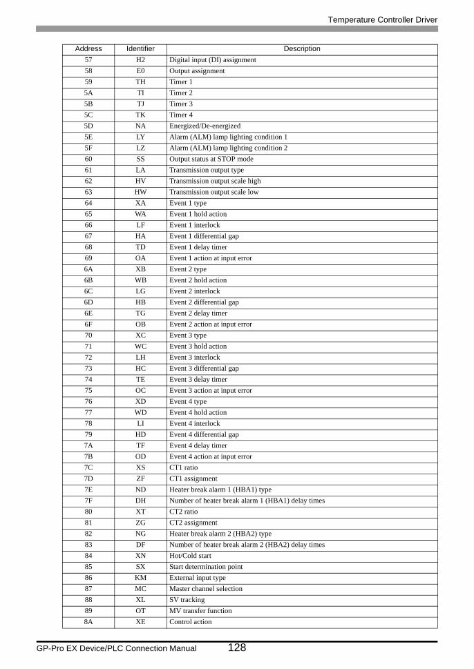
Temperature Controller Driver
GP-Pro EX Device/PLC Connection Manual 128
57 H2 Digital input (DI) assignment58 E0 Output assignment59 TH Timer 15A TI Timer 25B TJ Timer 35C TK Timer 45D NA Energized/De-energized5E LY Alarm (ALM) lamp lighting condition 15F LZ Alarm (ALM) lamp lighting condition 260 SS Output status at STOP mode61 LA Transmission output type62 HV Transmission output scale high63 HW Transmission output scale low64 XA Event 1 type65 WA Event 1 hold action66 LF Event 1 interlock67 HA Event 1 differential gap68 TD Event 1 delay timer69 OA Event 1 action at input error6A XB Event 2 type6B WB Event 2 hold action6C LG Event 2 interlock6D HB Event 2 differential gap6E TG Event 2 delay timer6F OB Event 2 action at input error70 XC Event 3 type71 WC Event 3 hold action72 LH Event 3 interlock73 HC Event 3 differential gap74 TE Event 3 delay timer75 OC Event 3 action at input error76 XD Event 4 type77 WD Event 4 hold action78 LI Event 4 interlock79 HD Event 4 differential gap7A TF Event 4 delay timer7B OD Event 4 action at input error7C XS CT1 ratio7D ZF CT1 assignment7E ND Heater break alarm 1 (HBA1) type7F DH Number of heater break alarm 1 (HBA1) delay times80 XT CT2 ratio81 ZG CT2 assignment82 NG Heater break alarm 2 (HBA2) type83 DF Number of heater break alarm 2 (HBA2) delay times84 XN Hot/Cold start85 SX Start determination point86 KM External input type87 MC Master channel selection88 XL SV tracking89 OT MV transfer function8A XE Control action
Address Identifier Description
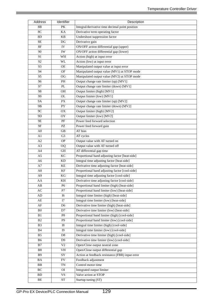
Temperature Controller Driver
GP-Pro EX Device/PLC Connection Manual 129
8B PK Integral/derivative time decimal point position8C KA Derivative term operating factor8D KB Undershoot suppression factor8E DG Derivative gain8F IV ON/OFF action differential gap (upper)90 IW ON/OFF action differential gap (lower)91 WH Action (high) at input error92 WL Action (low) at input error93 OE Manipulated output value at input error94 OF Manipulated output value (MV1) at STOP mode95 OG Manipulated output value (MV2) at STOP mode96 PH Output change rate limiter (up) [MV1]97 PL Output change rate limiter (down) [MV1]98 OH Output limiter (high) [MV1]99 OL Output limiter (low) [MV1]9A PX Output change rate limiter (up) [MV2]9B PY Output change rate limiter (down) [MV2]9C OX Output limiter (high) [MV2]9D OY Output limiter (low) [MV2]9E PF Power feed forward selection9F PZ Power feed forward gainA0 GB AT biasA1 G3 AT cyclesA2 OP Output value with AT turned onA3 OQ Output value with AT turned offA4 GH AT differential gap timeA5 KC Proportional band adjusting factor [heat-side]A6 KD Integral time adjusting factor [heat-side]A7 KE Derivative time adjusting factor [heat-side]A8 KF Proportional band adjusting factor [cool-side]A9 KG Integral time adjusting factor [cool-side]AA KH Derivative time adjusting factor [cool-side]AB P6 Proportional band limiter (high) [heat-side]AC P7 Proportional band limiter (low) [heat-side]AD I6 Integral time limiter (high) [heat-side]AE I7 Integral time limiter (low) [heat-side]AF D6 Derivative time limiter (high) [heat-side]B0 D7 Derivative time limiter (low) [heat-side]B1 P8 Proportional band limiter (high) [cool-side]B2 P9 Proportional band limiter (low) [cool-side]B3 I8 Integral time limiter (high) [cool-side]B4 I9 Integral time limiter (low) [cool-side]B5 D8 Derivative time limiter (high) [cool-side]B6 D9 Derivative time limiter (low) [cool-side]B7 V2 Open/Close output neutral zoneB8 VH Open/Close output differential gapB9 SY Action at feedback resistance (FBR) input errorBA FV Feedback adjustmentBB TN Control motor timeBC OI Integrated output limiterBD VS Valve action at STOPBE ST Startup tuning (ST)
Address Identifier Description
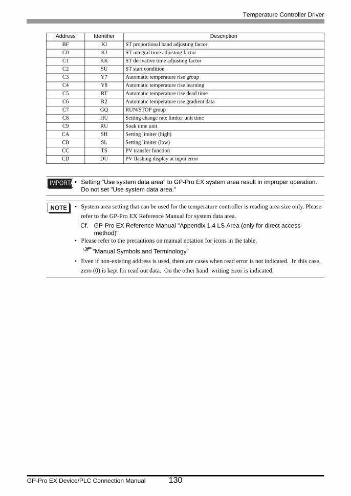
Temperature Controller Driver
GP-Pro EX Device/PLC Connection Manual 130
BF KI ST proportional band adjusting factorC0 KJ ST integral time adjusting factorC1 KK ST derivative time adjusting factorC2 SU ST start conditionC3 Y7 Automatic temperature rise groupC4 Y8 Automatic temperature rise learningC5 RT Automatic temperature rise dead timeC6 R2 Automatic temperature rise gradient dataC7 GQ RUN/STOP groupC8 HU Setting change rate limiter unit timeC9 RU Soak time unitCA SH Setting limiter (high)CB SL Setting limiter (low)CC TS PV transfer functionCD DU PV flashing display at input error
• Setting "Use system data area" to GP-Pro EX system area result in improper operation. Do not set "Use system data area."
• System area setting that can be used for the temperature controller is reading area size only. Please refer to the GP-Pro EX Reference Manual for system data area.Cf. GP-Pro EX Reference Manual "Appendix 1.4 LS Area (only for direct access
method)"• Please refer to the precautions on manual notation for icons in the table.
"Manual Symbols and Terminology"• Even if non-existing address is used, there are cases when read error is not indicated. In this case,
zero (0) is kept for read out data. On the other hand, writing error is indicated.
Address Identifier Description
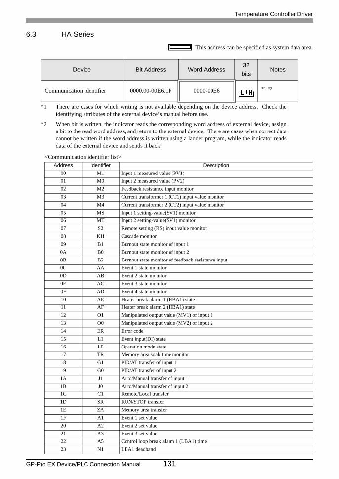
Temperature Controller Driver
GP-Pro EX Device/PLC Connection Manual 131
6.3 HA Series
This address can be specified as system data area.
<Communication identifier list>
Device Bit Address Word Address32bits
Notes
Communication identifier 0000.00-00E6.1F 0000-00E6 *1 *2
*1 There are cases for which writing is not available depending on the device address. Check the identifying attributes of the external device’s manual before use.
*2 When bit is written, the indicator reads the corresponding word address of external device, assign a bit to the read word address, and return to the external device. There are cases when correct data cannot be written if the word address is written using a ladder program, while the indicator reads data of the external device and sends it back.
Address Identifier Description00 M1 Input 1 measured value (PV1)01 M0 Input 2 measured value (PV2)02 M2 Feedback resistance input monitor03 M3 Current transformer 1 (CT1) input value monitor04 M4 Current transformer 2 (CT2) input value monitor05 MS Input 1 setting-value(SV1) monitor06 MT Input 2 setting-value(SV1) monitor07 S2 Remote setting (RS) input value monitor08 KH Cascade monitor09 B1 Burnout state monitor of input 10A B0 Burnout state monitor of input 20B B2 Burnout state monitor of feedback resistance input0C AA Event 1 state monitor0D AB Event 2 state monitor0E AC Event 3 state monitor0F AD Event 4 state monitor10 AE Heater break alarm 1 (HBA1) state11 AF Heater break alarm 2 (HBA1) state12 O1 Manipulated output value (MV1) of input 113 O0 Manipulated output value (MV2) of input 214 ER Error code15 L1 Event input(DI) state16 L0 Operation mode state17 TR Memory area soak time monitor18 G1 PID/AT transfer of input 119 G0 PID/AT transfer of input 21A J1 Auto/Manual transfer of input 11B J0 Auto/Manual transfer of input 21C C1 Remote/Local transfer1D SR RUN/STOP transfer1E ZA Memory area transfer1F A1 Event 1 set value20 A2 Event 2 set value21 A3 Event 3 set value22 A5 Control loop break alarm 1 (LBA1) time23 N1 LBA1 deadband
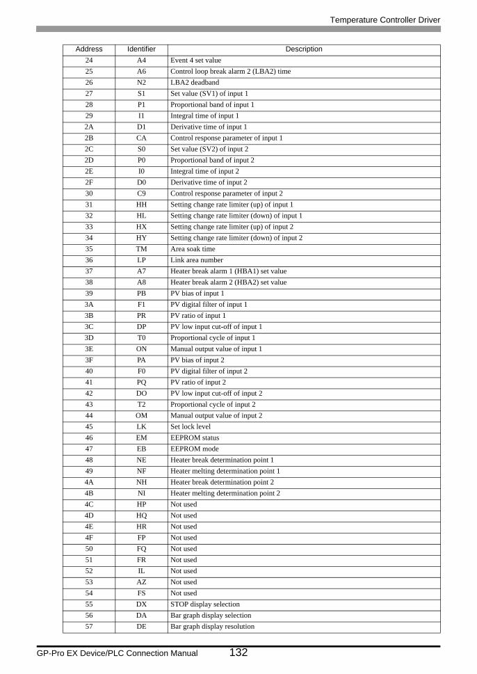
Temperature Controller Driver
GP-Pro EX Device/PLC Connection Manual 132
24 A4 Event 4 set value25 A6 Control loop break alarm 2 (LBA2) time26 N2 LBA2 deadband27 S1 Set value (SV1) of input 128 P1 Proportional band of input 129 I1 Integral time of input 12A D1 Derivative time of input 12B CA Control response parameter of input 12C S0 Set value (SV2) of input 22D P0 Proportional band of input 22E I0 Integral time of input 22F D0 Derivative time of input 230 C9 Control response parameter of input 231 HH Setting change rate limiter (up) of input 132 HL Setting change rate limiter (down) of input 133 HX Setting change rate limiter (up) of input 234 HY Setting change rate limiter (down) of input 235 TM Area soak time36 LP Link area number37 A7 Heater break alarm 1 (HBA1) set value38 A8 Heater break alarm 2 (HBA2) set value39 PB PV bias of input 13A F1 PV digital filter of input 13B PR PV ratio of input 13C DP PV low input cut-off of input 13D T0 Proportional cycle of input 13E ON Manual output value of input 13F PA PV bias of input 240 F0 PV digital filter of input 241 PQ PV ratio of input 242 DO PV low input cut-off of input 243 T2 Proportional cycle of input 244 OM Manual output value of input 245 LK Set lock level46 EM EEPROM status47 EB EEPROM mode48 NE Heater break determination point 149 NF Heater melting determination point 14A NH Heater break determination point 24B NI Heater melting determination point 24C HP Not used4D HQ Not used4E HR Not used4F FP Not used50 FQ Not used51 FR Not used52 IL Not used53 AZ Not used54 FS Not used55 DX STOP display selection56 DA Bar graph display selection57 DE Bar graph display resolution
Address Identifier Description
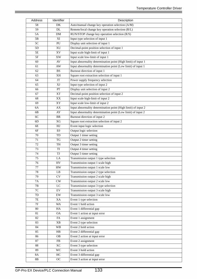
Temperature Controller Driver
GP-Pro EX Device/PLC Connection Manual 133
58 DK Auto/manual change key operation selection (A/M)59 DL Remote/local change key operation selection (R/L)5A DM RUN/STOP change key operation selection (R/S)5B XI Input type selection of input 15C PU Display unit selection of input 15D XU Decimal-point position selection of input 15E XV Input scale high-limit of input 15F XW Input scale low-limit of input 160 AV Input abnormality determination point (High limit) of input 161 AW Input abnormality determination point (Low limit) of input 162 BS Burnout direction of input 163 XH Square root extraction selection of input 164 JT Power supply frequency selection65 XJ Input type selection of input 266 PT Display unit selection of input 267 XT Decimal-point position selection of input 268 XX Input scale high-limit of input 269 XY Input scale low-limit of input 26A AX Input abnormality determination point (High limit) of input 26B AY Input abnormality determination point (Low limit) of input 26C BR Burnout direction of input 26D XG Square root extraction selection of input 26E H2 Event input logic selection6F E0 Output logic selection70 TD Output 1 timer setting71 TG Output 2 timer setting72 TH Output 3 timer setting73 TI Output 4 timer setting74 TJ Output 5 timer setting75 LA Transmission output 1 type selection76 HV Transmission output 1 scale high77 HW Transmission output 1 scale low78 LB Transmission output 2 type selection79 CV Transmission output 2 scale high7A CW Transmission output 2 scale low7B LC Transmission output 3 type selection7C EV Transmission output 3 scale high7D EW Transmission output 3 scale low7E XA Event 1 type selection7F WA Event 1 hold action80 HA Event 1 differential gap81 OA Event 1 action at input error82 FA Event 1 assignment83 XB Event 2 type selection84 WB Event 2 hold action85 HB Event 2 differential gap86 OB Event 2 action at input error87 FB Event 2 assignment88 XC Event 3 type selection89 WC Event 3 hold action8A HC Event 3 differential gap8B OC Event 3 action at input error
Address Identifier Description
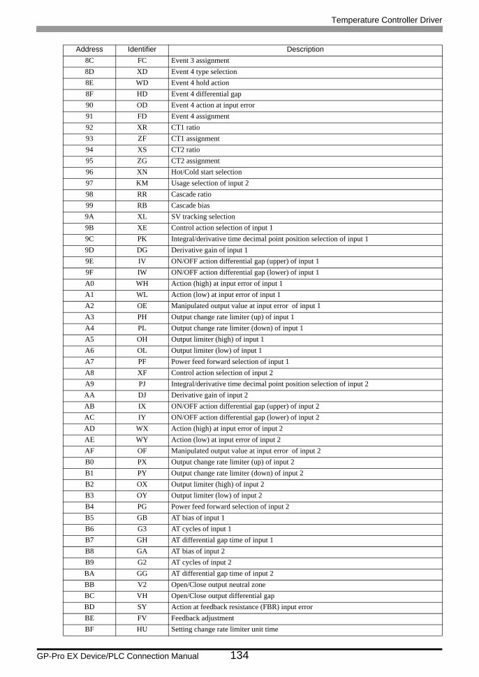
Temperature Controller Driver
GP-Pro EX Device/PLC Connection Manual 134
8C FC Event 3 assignment8D XD Event 4 type selection8E WD Event 4 hold action8F HD Event 4 differential gap90 OD Event 4 action at input error91 FD Event 4 assignment92 XR CT1 ratio93 ZF CT1 assignment94 XS CT2 ratio95 ZG CT2 assignment96 XN Hot/Cold start selection97 KM Usage selection of input 298 RR Cascade ratio99 RB Cascade bias9A XL SV tracking selection9B XE Control action selection of input 19C PK Integral/derivative time decimal point position selection of input 19D DG Derivative gain of input 19E IV ON/OFF action differential gap (upper) of input 19F IW ON/OFF action differential gap (lower) of input 1A0 WH Action (high) at input error of input 1A1 WL Action (low) at input error of input 1A2 OE Manipulated output value at input error of input 1A3 PH Output change rate limiter (up) of input 1A4 PL Output change rate limiter (down) of input 1A5 OH Output limiter (high) of input 1A6 OL Output limiter (low) of input 1A7 PF Power feed forward selection of input 1A8 XF Control action selection of input 2A9 PJ Integral/derivative time decimal point position selection of input 2AA DJ Derivative gain of input 2AB IX ON/OFF action differential gap (upper) of input 2AC IY ON/OFF action differential gap (lower) of input 2AD WX Action (high) at input error of input 2AE WY Action (low) at input error of input 2AF OF Manipulated output value at input error of input 2B0 PX Output change rate limiter (up) of input 2B1 PY Output change rate limiter (down) of input 2B2 OX Output limiter (high) of input 2B3 OY Output limiter (low) of input 2B4 PG Power feed forward selection of input 2B5 GB AT bias of input 1B6 G3 AT cycles of input 1B7 GH AT differential gap time of input 1B8 GA AT bias of input 2B9 G2 AT cycles of input 2BA GG AT differential gap time of input 2BB V2 Open/Close output neutral zoneBC VH Open/Close output differential gapBD SY Action at feedback resistance (FBR) input errorBE FV Feedback adjustmentBF HU Setting change rate limiter unit time
Address Identifier Description
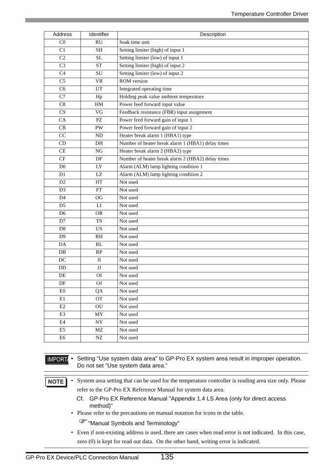
Temperature Controller Driver
GP-Pro EX Device/PLC Connection Manual 135
C0 RU Soak time unitC1 SH Setting limiter (high) of input 1C2 SL Setting limiter (low) of input 1C3 ST Setting limiter (high) of input 2C4 SU Setting limiter (low) of input 2C5 VR ROM versionC6 UT Integrated operating timeC7 Hp Holding peak value ambient temperatureC8 HM Power feed forward input valueC9 VG Feedback resistance (FBR) input assignmentCA PZ Power feed forward gain of input 1CB PW Power feed forward gain of input 2CC ND Heater break alarm 1 (HBA1) typeCD DH Number of heater break alarm 1 (HBA1) delay timesCE NG Heater break alarm 2 (HBA2) typeCF DF Number of heater break alarm 2 (HBA2) delay timesD0 LY Alarm (ALM) lamp lighting condition 1D1 LZ Alarm (ALM) lamp lighting condition 2D2 HT Not usedD3 FT Not usedD4 OG Not usedD5 LI Not usedD6 OR Not usedD7 TS Not usedD8 US Not usedD9 RH Not usedDA RL Not usedDB RP Not usedDC JI Not usedDD JJ Not usedDE OI Not usedDF OJ Not usedE0 QA Not usedE1 OT Not usedE2 OU Not usedE3 MY Not usedE4 NY Not usedE5 MZ Not usedE6 NZ Not used
• Setting "Use system data area" to GP-Pro EX system area result in improper operation. Do not set "Use system data area."
• System area setting that can be used for the temperature controller is reading area size only. Please refer to the GP-Pro EX Reference Manual for system data area.Cf. GP-Pro EX Reference Manual "Appendix 1.4 LS Area (only for direct access
method)"• Please refer to the precautions on manual notation for icons in the table.
"Manual Symbols and Terminology"• Even if non-existing address is used, there are cases when read error is not indicated. In this case,
zero (0) is kept for read out data. On the other hand, writing error is indicated.
Address Identifier Description
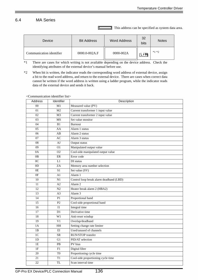
Temperature Controller Driver
GP-Pro EX Device/PLC Connection Manual 136
6.4 MA Series
This address can be specified as system data area.
<Communication identifier list>
Device Bit Address Word Address32bits
Notes
Communication identifier 0000.0-002A.F 0000-002A *1 *2
*1 There are cases for which writing is not available depending on the device address. Check the identifying attributes of the external device’s manual before use.
*2 When bit is written, the indicator reads the corresponding word address of external device, assign a bit to the read word address, and return to the external device. There are cases when correct data cannot be written if the word address is written using a ladder program, while the indicator reads data of the external device and sends it back.
Address Identifier Description00 M1 Measured value (PV)01 M2 Current transformer 1 input value02 M3 Current transformer 2 input value03 MS Set value monitor04 B1 Burnout05 AA Alarm 1 status06 AB Alarm 2 status07 AC Alarm 3 status08 AJ Output status09 O1 Manipulated output value0A O2 Cool-side manipulated output value0B ER Error code0C L1 DI status0D ZA Memory area number selection0E S1 Set value (SV)0F A1 Alarm 110 N1 Control loop break alarm deadband (LBD)11 A2 Alarm 212 N2 Heater break alarm 2 (HBA2)13 A3 Alarm 314 P1 Proportional band15 P2 Cool-side proportional band16 I1 Integral time17 D1 Derivative time18 W1 Anti-reset windup19 V1 Overlap/deadband1A HH Setting change rate limiter1B EI Used/unused of channels1C SR RUN/STOP transfer1D G1 PID/AT selection1E PB PV bias1F F1 Digital filter20 T0 Proportioning cycle time21 T1 Cool-side proportioning cycle time22 TL Scan interval time
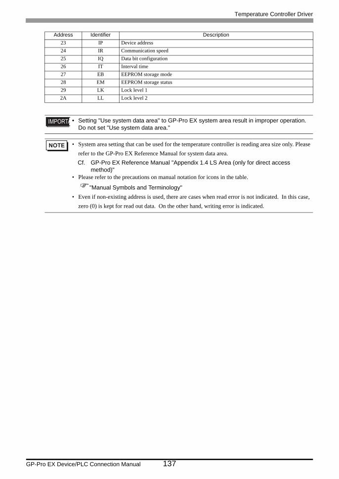
Temperature Controller Driver
GP-Pro EX Device/PLC Connection Manual 137
23 IP Device address24 IR Communication speed25 IQ Data bit configuration26 IT Interval time27 EB EEPROM storage mode28 EM EEPROM storage status29 LK Lock level 12A LL Lock level 2
• Setting "Use system data area" to GP-Pro EX system area result in improper operation. Do not set "Use system data area."
• System area setting that can be used for the temperature controller is reading area size only. Please refer to the GP-Pro EX Reference Manual for system data area.Cf. GP-Pro EX Reference Manual "Appendix 1.4 LS Area (only for direct access
method)"• Please refer to the precautions on manual notation for icons in the table.
"Manual Symbols and Terminology"• Even if non-existing address is used, there are cases when read error is not indicated. In this case,
zero (0) is kept for read out data. On the other hand, writing error is indicated.
Address Identifier Description
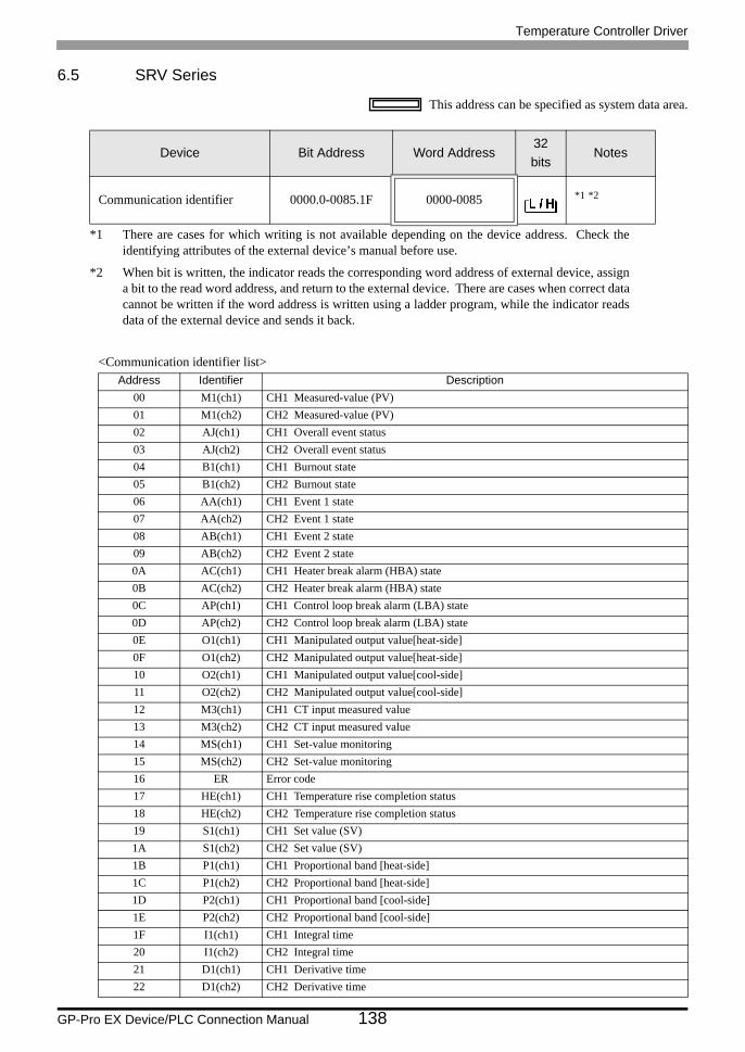
Temperature Controller Driver
GP-Pro EX Device/PLC Connection Manual 138
6.5 SRV Series
This address can be specified as system data area.
<Communication identifier list>
Device Bit Address Word Address32bits
Notes
Communication identifier 0000.0-0085.1F 0000-0085 *1 *2
*1 There are cases for which writing is not available depending on the device address. Check the identifying attributes of the external device’s manual before use.
*2 When bit is written, the indicator reads the corresponding word address of external device, assign a bit to the read word address, and return to the external device. There are cases when correct data cannot be written if the word address is written using a ladder program, while the indicator reads data of the external device and sends it back.
Address Identifier Description00 M1(ch1) CH1 Measured-value (PV)01 M1(ch2) CH2 Measured-value (PV)02 AJ(ch1) CH1 Overall event status03 AJ(ch2) CH2 Overall event status04 B1(ch1) CH1 Burnout state05 B1(ch2) CH2 Burnout state06 AA(ch1) CH1 Event 1 state07 AA(ch2) CH2 Event 1 state08 AB(ch1) CH1 Event 2 state09 AB(ch2) CH2 Event 2 state0A AC(ch1) CH1 Heater break alarm (HBA) state0B AC(ch2) CH2 Heater break alarm (HBA) state0C AP(ch1) CH1 Control loop break alarm (LBA) state0D AP(ch2) CH2 Control loop break alarm (LBA) state0E O1(ch1) CH1 Manipulated output value[heat-side]0F O1(ch2) CH2 Manipulated output value[heat-side]10 O2(ch1) CH1 Manipulated output value[cool-side]11 O2(ch2) CH2 Manipulated output value[cool-side]12 M3(ch1) CH1 CT input measured value13 M3(ch2) CH2 CT input measured value14 MS(ch1) CH1 Set-value monitoring15 MS(ch2) CH2 Set-value monitoring16 ER Error code17 HE(ch1) CH1 Temperature rise completion status18 HE(ch2) CH2 Temperature rise completion status19 S1(ch1) CH1 Set value (SV)1A S1(ch2) CH2 Set value (SV)1B P1(ch1) CH1 Proportional band [heat-side]1C P1(ch2) CH2 Proportional band [heat-side]1D P2(ch1) CH1 Proportional band [cool-side]1E P2(ch2) CH2 Proportional band [cool-side]1F I1(ch1) CH1 Integral time20 I1(ch2) CH2 Integral time21 D1(ch1) CH1 Derivative time22 D1(ch2) CH2 Derivative time
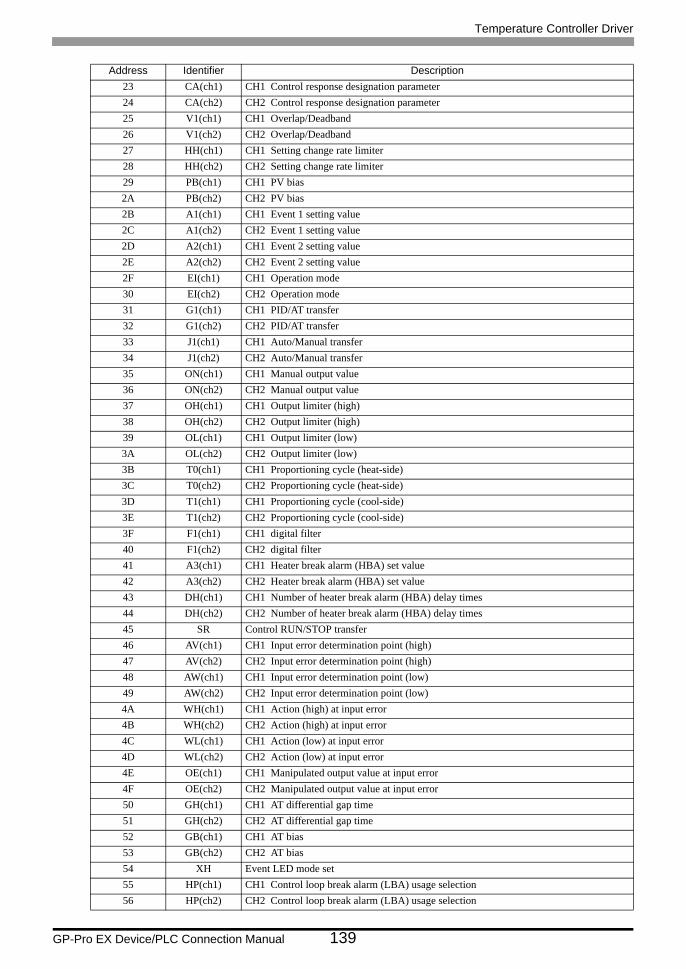
Temperature Controller Driver
GP-Pro EX Device/PLC Connection Manual 139
23 CA(ch1) CH1 Control response designation parameter24 CA(ch2) CH2 Control response designation parameter25 V1(ch1) CH1 Overlap/Deadband26 V1(ch2) CH2 Overlap/Deadband27 HH(ch1) CH1 Setting change rate limiter28 HH(ch2) CH2 Setting change rate limiter29 PB(ch1) CH1 PV bias2A PB(ch2) CH2 PV bias2B A1(ch1) CH1 Event 1 setting value2C A1(ch2) CH2 Event 1 setting value2D A2(ch1) CH1 Event 2 setting value2E A2(ch2) CH2 Event 2 setting value2F EI(ch1) CH1 Operation mode30 EI(ch2) CH2 Operation mode31 G1(ch1) CH1 PID/AT transfer32 G1(ch2) CH2 PID/AT transfer33 J1(ch1) CH1 Auto/Manual transfer34 J1(ch2) CH2 Auto/Manual transfer35 ON(ch1) CH1 Manual output value36 ON(ch2) CH2 Manual output value37 OH(ch1) CH1 Output limiter (high)38 OH(ch2) CH2 Output limiter (high)39 OL(ch1) CH1 Output limiter (low)3A OL(ch2) CH2 Output limiter (low)3B T0(ch1) CH1 Proportioning cycle (heat-side)3C T0(ch2) CH2 Proportioning cycle (heat-side)3D T1(ch1) CH1 Proportioning cycle (cool-side)3E T1(ch2) CH2 Proportioning cycle (cool-side)3F F1(ch1) CH1 digital filter40 F1(ch2) CH2 digital filter41 A3(ch1) CH1 Heater break alarm (HBA) set value42 A3(ch2) CH2 Heater break alarm (HBA) set value43 DH(ch1) CH1 Number of heater break alarm (HBA) delay times44 DH(ch2) CH2 Number of heater break alarm (HBA) delay times45 SR Control RUN/STOP transfer46 AV(ch1) CH1 Input error determination point (high)47 AV(ch2) CH2 Input error determination point (high)48 AW(ch1) CH1 Input error determination point (low)49 AW(ch2) CH2 Input error determination point (low)4A WH(ch1) CH1 Action (high) at input error4B WH(ch2) CH2 Action (high) at input error4C WL(ch1) CH1 Action (low) at input error4D WL(ch2) CH2 Action (low) at input error4E OE(ch1) CH1 Manipulated output value at input error4F OE(ch2) CH2 Manipulated output value at input error50 GH(ch1) CH1 AT differential gap time51 GH(ch2) CH2 AT differential gap time52 GB(ch1) CH1 AT bias53 GB(ch2) CH2 AT bias54 XH Event LED mode set55 HP(ch1) CH1 Control loop break alarm (LBA) usage selection56 HP(ch2) CH2 Control loop break alarm (LBA) usage selection
Address Identifier Description
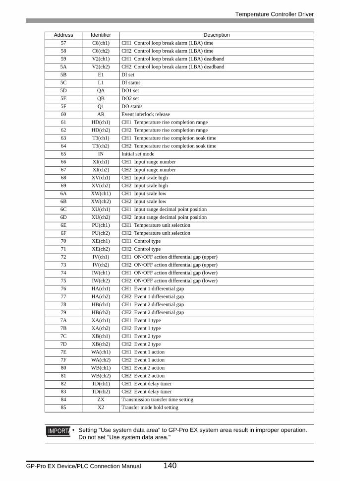
Temperature Controller Driver
GP-Pro EX Device/PLC Connection Manual 140
57 C6(ch1) CH1 Control loop break alarm (LBA) time58 C6(ch2) CH2 Control loop break alarm (LBA) time59 V2(ch1) CH1 Control loop break alarm (LBA) deadband5A V2(ch2) CH2 Control loop break alarm (LBA) deadband5B E1 DI set5C L1 DI status5D QA DO1 set5E QB DO2 set5F Q1 DO status60 AR Event interlock release61 HD(ch1) CH1 Temperature rise completion range62 HD(ch2) CH2 Temperature rise completion range63 T3(ch1) CH1 Temperature rise completion soak time64 T3(ch2) CH2 Temperature rise completion soak time65 IN Initial set mode66 XI(ch1) CH1 Input range number67 XI(ch2) CH2 Input range number68 XV(ch1) CH1 Input scale high69 XV(ch2) CH2 Input scale high6A XW(ch1) CH1 Input scale low6B XW(ch2) CH2 Input scale low6C XU(ch1) CH1 Input range decimal point position6D XU(ch2) CH2 Input range decimal point position6E PU(ch1) CH1 Temperature unit selection6F PU(ch2) CH2 Temperature unit selection70 XE(ch1) CH1 Control type71 XE(ch2) CH2 Control type72 IV(ch1) CH1 ON/OFF action differential gap (upper)73 IV(ch2) CH2 ON/OFF action differential gap (upper)74 IW(ch1) CH1 ON/OFF action differential gap (lower)75 IW(ch2) CH2 ON/OFF action differential gap (lower)76 HA(ch1) CH1 Event 1 differential gap77 HA(ch2) CH2 Event 1 differential gap78 HB(ch1) CH1 Event 2 differential gap79 HB(ch2) CH2 Event 2 differential gap7A XA(ch1) CH1 Event 1 type7B XA(ch2) CH2 Event 1 type7C XB(ch1) CH1 Event 2 type7D XB(ch2) CH2 Event 2 type7E WA(ch1) CH1 Event 1 action7F WA(ch2) CH2 Event 1 action80 WB(ch1) CH1 Event 2 action81 WB(ch2) CH2 Event 2 action82 TD(ch1) CH1 Event delay timer83 TD(ch2) CH2 Event delay timer84 ZX Transmission transfer time setting85 X2 Transfer mode hold setting
• Setting "Use system data area" to GP-Pro EX system area result in improper operation. Do not set "Use system data area."
Address Identifier Description
Temperature Controller Driver
GP-Pro EX Device/PLC Connection Manual 141
• System area setting that can be used for the temperature controller is reading area size only. Please refer to the GP-Pro EX Reference Manual for system data area.Cf. GP-Pro EX Reference Manual "Appendix 1.4 LS Area (only for direct access
method)"• Please refer to the precautions on manual notation for icons in the table.
"Manual Symbols and Terminology"• Even if non-existing address is used, there are cases when read error is not indicated. In this case,
zero (0) is kept for read out data. On the other hand, writing error is indicated.
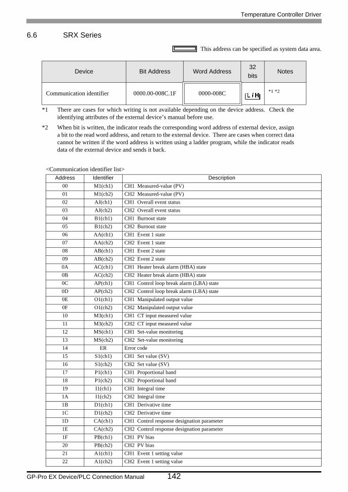
Temperature Controller Driver
GP-Pro EX Device/PLC Connection Manual 142
6.6 SRX Series
This address can be specified as system data area.
<Communication identifier list>
Device Bit Address Word Address32bits
Notes
Communication identifier 0000.00-008C.1F 0000-008C *1 *2
*1 There are cases for which writing is not available depending on the device address. Check the identifying attributes of the external device’s manual before use.
*2 When bit is written, the indicator reads the corresponding word address of external device, assign a bit to the read word address, and return to the external device. There are cases when correct data cannot be written if the word address is written using a ladder program, while the indicator reads data of the external device and sends it back.
Address Identifier Description00 M1(ch1) CH1 Measured-value (PV)01 M1(ch2) CH2 Measured-value (PV)02 AJ(ch1) CH1 Overall event status03 AJ(ch2) CH2 Overall event status04 B1(ch1) CH1 Burnout state05 B1(ch2) CH2 Burnout state06 AA(ch1) CH1 Event 1 state07 AA(ch2) CH2 Event 1 state08 AB(ch1) CH1 Event 2 state09 AB(ch2) CH2 Event 2 state0A AC(ch1) CH1 Heater break alarm (HBA) state0B AC(ch2) CH2 Heater break alarm (HBA) state0C AP(ch1) CH1 Control loop break alarm (LBA) state0D AP(ch2) CH2 Control loop break alarm (LBA) state0E O1(ch1) CH1 Manipulated output value0F O1(ch2) CH2 Manipulated output value10 M3(ch1) CH1 CT input measured value11 M3(ch2) CH2 CT input measured value12 MS(ch1) CH1 Set-value monitoring13 MS(ch2) CH2 Set-value monitoring14 ER Error code 15 S1(ch1) CH1 Set value (SV)16 S1(ch2) CH2 Set value (SV)17 P1(ch1) CH1 Proportional band18 P1(ch2) CH2 Proportional band19 I1(ch1) CH1 Integral time1A I1(ch2) CH2 Integral time1B D1(ch1) CH1 Derivative time1C D1(ch2) CH2 Derivative time1D CA(ch1) CH1 Control response designation parameter1E CA(ch2) CH2 Control response designation parameter1F PB(ch1) CH1 PV bias20 PB(ch2) CH2 PV bias21 A1(ch1) CH1 Event 1 setting value22 A1(ch2) CH2 Event 1 setting value
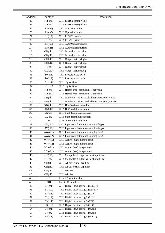
Temperature Controller Driver
GP-Pro EX Device/PLC Connection Manual 143
23 A2(ch1) CH1 Event 2 setting value24 A2(ch2) CH2 Event 2 setting value25 EI(ch1) CH1 Operation mode26 EI(ch2) CH2 Operation mode27 G1(ch1) CH1 PID/AT transfer28 G1(ch2) CH2 PID/AT transfer29 J1(ch1) CH1 Auto/Manual transfer2A J1(ch2) CH2 Auto/Manual transfer2B ON(ch1) CH1 Manual output value2C ON(ch2) CH2 Manual output value2D OH(ch1) CH1 Output limiter (high)2E OH(ch2) CH2 Output limiter (high)2F OL(ch1) CH1 Output limiter (low)30 OL(ch2) CH2 Output limiter (low)31 T0(ch1) CH1 Proportioning cycle32 T0(ch2) CH2 Proportioning cycle33 F1(ch1) CH1 digital filter34 F1(ch2) CH2 digital filter35 A3(ch1) CH1 Heater break alarm (HBA) set value36 A3(ch2) CH2 Heater break alarm (HBA) set value37 DH(ch1) CH1 Number of heater break alarm (HBA) delay times38 DH(ch2) CH2 Number of heater break alarm (HBA) delay times39 XN(ch1) CH1 Hot/Cold start selection3A XN(ch2) CH2 Hot/Cold start selection3B SX(ch1) CH1 Start determination point3C SX(ch2) CH2 Start determination point3D SR Control RUN/STOP transfer 3E AV(ch1) CH1 Input error determination point (high)3F AV(ch2) CH2 Input error determination point (high)40 AW(ch1) CH1 Input error determination point (low)41 AW(ch2) CH2 Input error determination point (low)42 WH(ch1) CH1 Action (high) at input error43 WH(ch2) CH2 Action (high) at input error44 WL(ch1) CH1 Action (low) at input error45 WL(ch2) CH2 Action (low) at input error46 OE(ch1) CH1 Manipulated output value at input error47 OE(ch2) CH2 Manipulated output value at input error48 GH(ch1) CH1 AT differential gap time49 GH(ch2) CH2 AT differential gap time4A GB(ch1) CH1 AT bias4B GB(ch2) CH2 AT bias4C C1 Remote/Local transfer 4D XH Event LED mode set4E E1(ch1) CH1 Digital input setting 1 (RESET)4F E1(ch2) CH2 Digital input setting 1 (RESET)50 E2(ch1) CH1 Digital input setting 2 (RUN)51 E2(ch2) CH2 Digital input setting 2 (RUN)52 E3(ch1) CH1 Digital input setting 3 (FIX)53 E3(ch2) CH2 Digital input setting 3 (FIX)54 E4(ch1) CH1 Digital input setting 4 (MAN)55 E4(ch2) CH2 Digital input setting 4 (MAN)56 E5(ch1) CH1 Digital input setting 5 (HOLD)
Address Identifier Description
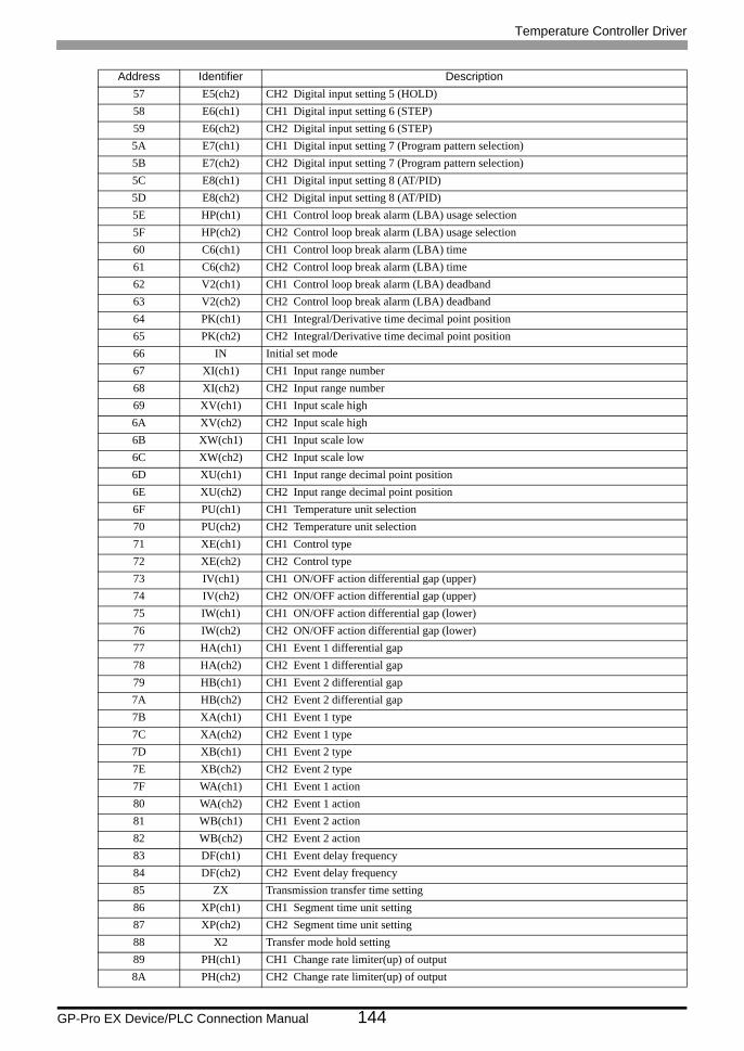
Temperature Controller Driver
GP-Pro EX Device/PLC Connection Manual 144
57 E5(ch2) CH2 Digital input setting 5 (HOLD)58 E6(ch1) CH1 Digital input setting 6 (STEP)59 E6(ch2) CH2 Digital input setting 6 (STEP)5A E7(ch1) CH1 Digital input setting 7 (Program pattern selection)5B E7(ch2) CH2 Digital input setting 7 (Program pattern selection)5C E8(ch1) CH1 Digital input setting 8 (AT/PID)5D E8(ch2) CH2 Digital input setting 8 (AT/PID)5E HP(ch1) CH1 Control loop break alarm (LBA) usage selection5F HP(ch2) CH2 Control loop break alarm (LBA) usage selection60 C6(ch1) CH1 Control loop break alarm (LBA) time61 C6(ch2) CH2 Control loop break alarm (LBA) time62 V2(ch1) CH1 Control loop break alarm (LBA) deadband63 V2(ch2) CH2 Control loop break alarm (LBA) deadband64 PK(ch1) CH1 Integral/Derivative time decimal point position65 PK(ch2) CH2 Integral/Derivative time decimal point position66 IN Initial set mode67 XI(ch1) CH1 Input range number68 XI(ch2) CH2 Input range number69 XV(ch1) CH1 Input scale high6A XV(ch2) CH2 Input scale high6B XW(ch1) CH1 Input scale low6C XW(ch2) CH2 Input scale low6D XU(ch1) CH1 Input range decimal point position6E XU(ch2) CH2 Input range decimal point position6F PU(ch1) CH1 Temperature unit selection70 PU(ch2) CH2 Temperature unit selection71 XE(ch1) CH1 Control type72 XE(ch2) CH2 Control type73 IV(ch1) CH1 ON/OFF action differential gap (upper)74 IV(ch2) CH2 ON/OFF action differential gap (upper)75 IW(ch1) CH1 ON/OFF action differential gap (lower)76 IW(ch2) CH2 ON/OFF action differential gap (lower)77 HA(ch1) CH1 Event 1 differential gap78 HA(ch2) CH2 Event 1 differential gap79 HB(ch1) CH1 Event 2 differential gap7A HB(ch2) CH2 Event 2 differential gap7B XA(ch1) CH1 Event 1 type7C XA(ch2) CH2 Event 1 type7D XB(ch1) CH1 Event 2 type7E XB(ch2) CH2 Event 2 type7F WA(ch1) CH1 Event 1 action80 WA(ch2) CH2 Event 1 action81 WB(ch1) CH1 Event 2 action82 WB(ch2) CH2 Event 2 action83 DF(ch1) CH1 Event delay frequency84 DF(ch2) CH2 Event delay frequency85 ZX Transmission transfer time setting86 XP(ch1) CH1 Segment time unit setting87 XP(ch2) CH2 Segment time unit setting88 X2 Transfer mode hold setting89 PH(ch1) CH1 Change rate limiter(up) of output8A PH(ch2) CH2 Change rate limiter(up) of output
Address Identifier Description
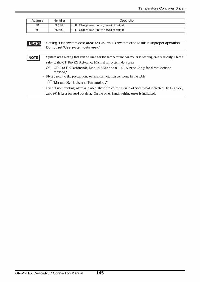
Temperature Controller Driver
GP-Pro EX Device/PLC Connection Manual 145
8B PL(ch1) CH1 Change rate limiter(down) of output8C PL(ch2) CH2 Change rate limiter(down) of output
• Setting "Use system data area" to GP-Pro EX system area result in improper operation. Do not set "Use system data area."
• System area setting that can be used for the temperature controller is reading area size only. Please refer to the GP-Pro EX Reference Manual for system data area.Cf. GP-Pro EX Reference Manual "Appendix 1.4 LS Area (only for direct access
method)"• Please refer to the precautions on manual notation for icons in the table.
"Manual Symbols and Terminology"• Even if non-existing address is used, there are cases when read error is not indicated. In this case,
zero (0) is kept for read out data. On the other hand, writing error is indicated.
Address Identifier Description
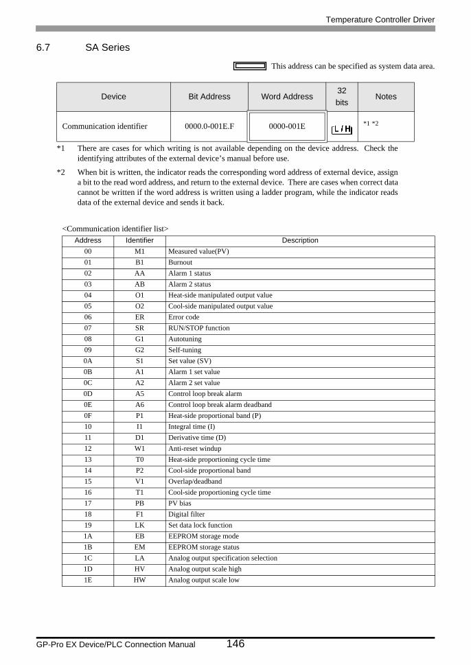
Temperature Controller Driver
GP-Pro EX Device/PLC Connection Manual 146
6.7 SA Series
This address can be specified as system data area.
<Communication identifier list>
Device Bit Address Word Address32bits
Notes
Communication identifier 0000.0-001E.F 0000-001E *1 *2
*1 There are cases for which writing is not available depending on the device address. Check the identifying attributes of the external device’s manual before use.
*2 When bit is written, the indicator reads the corresponding word address of external device, assign a bit to the read word address, and return to the external device. There are cases when correct data cannot be written if the word address is written using a ladder program, while the indicator reads data of the external device and sends it back.
Address Identifier Description00 M1 Measured value(PV)01 B1 Burnout02 AA Alarm 1 status03 AB Alarm 2 status04 O1 Heat-side manipulated output value05 O2 Cool-side manipulated output value06 ER Error code07 SR RUN/STOP function08 G1 Autotuning09 G2 Self-tuning0A S1 Set value (SV)0B A1 Alarm 1 set value0C A2 Alarm 2 set value0D A5 Control loop break alarm0E A6 Control loop break alarm deadband0F P1 Heat-side proportional band (P)10 I1 Integral time (I)11 D1 Derivative time (D)12 W1 Anti-reset windup13 T0 Heat-side proportioning cycle time14 P2 Cool-side proportional band15 V1 Overlap/deadband16 T1 Cool-side proportioning cycle time17 PB PV bias18 F1 Digital filter19 LK Set data lock function1A EB EEPROM storage mode1B EM EEPROM storage status1C LA Analog output specification selection1D HV Analog output scale high1E HW Analog output scale low

Temperature Controller Driver
GP-Pro EX Device/PLC Connection Manual 147
• Setting "Use system data area" to GP-Pro EX system area result in improper operation. Do not set "Use system data area."
• System area setting that can be used for the temperature controller is reading area size only. Please refer to the GP-Pro EX Reference Manual for system data area.Cf. GP-Pro EX Reference Manual "Appendix 1.4 LS Area (only for direct access
method)"• Please refer to the precautions on manual notation for icons in the table.
"Manual Symbols and Terminology"• Even if non-existing address is used, there are cases when read error is not indicated. In this case,
zero (0) is kept for read out data. On the other hand, writing error is indicated.
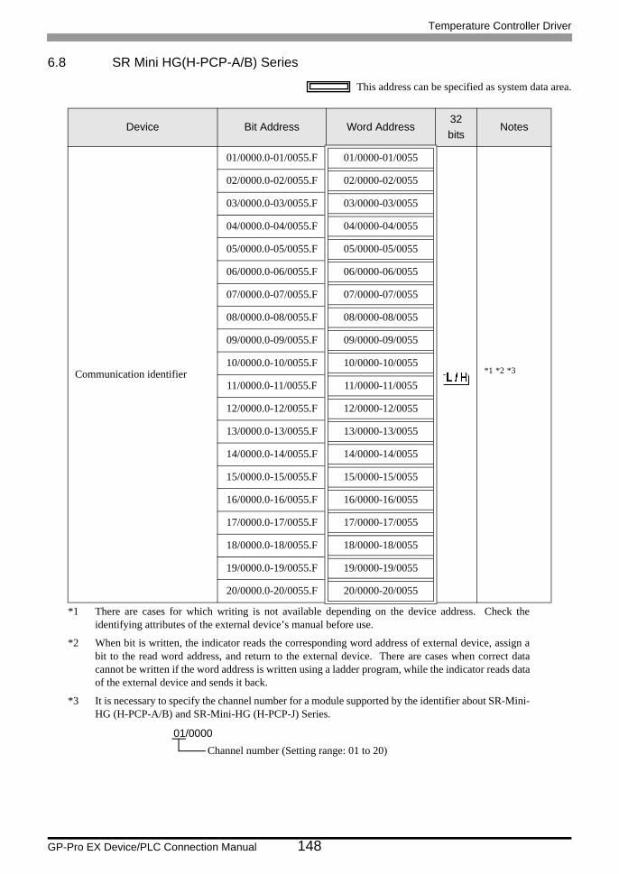
Temperature Controller Driver
GP-Pro EX Device/PLC Connection Manual 148
6.8 SR Mini HG(H-PCP-A/B) Series
This address can be specified as system data area.
Device Bit Address Word Address32bits
Notes
Communication identifier
01/0000.0-01/0055.F 01/0000-01/0055
*1 *2 *3
*1 There are cases for which writing is not available depending on the device address. Check the identifying attributes of the external device’s manual before use.
*2 When bit is written, the indicator reads the corresponding word address of external device, assign a bit to the read word address, and return to the external device. There are cases when correct data cannot be written if the word address is written using a ladder program, while the indicator reads data of the external device and sends it back.
*3 It is necessary to specify the channel number for a module supported by the identifier about SR-Mini- HG (H-PCP-A/B) and SR-Mini-HG (H-PCP-J) Series.
02/0000.0-02/0055.F 02/0000-02/0055
03/0000.0-03/0055.F 03/0000-03/0055
04/0000.0-04/0055.F 04/0000-04/0055
05/0000.0-05/0055.F 05/0000-05/0055
06/0000.0-06/0055.F 06/0000-06/0055
07/0000.0-07/0055.F 07/0000-07/0055
08/0000.0-08/0055.F 08/0000-08/0055
09/0000.0-09/0055.F 09/0000-09/0055
10/0000.0-10/0055.F 10/0000-10/0055
11/0000.0-11/0055.F 11/0000-11/0055
12/0000.0-12/0055.F 12/0000-12/0055
13/0000.0-13/0055.F 13/0000-13/0055
14/0000.0-14/0055.F 14/0000-14/0055
15/0000.0-15/0055.F 15/0000-15/0055
16/0000.0-16/0055.F 16/0000-16/0055
17/0000.0-17/0055.F 17/0000-17/0055
18/0000.0-18/0055.F 18/0000-18/0055
19/0000.0-19/0055.F 19/0000-19/0055
20/0000.0-20/0055.F 20/0000-20/0055
01/0000Channel number (Setting range: 01 to 20)
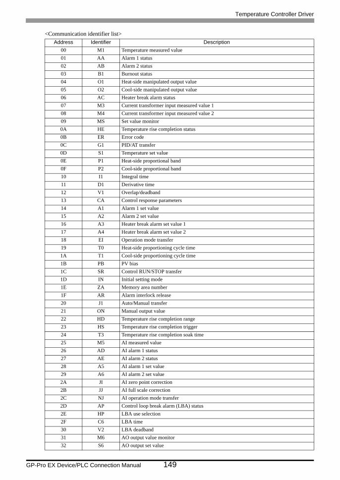
Temperature Controller Driver
GP-Pro EX Device/PLC Connection Manual 149
<Communication identifier list>Address Identifier Description
00 M1 Temperature measured value01 AA Alarm 1 status02 AB Alarm 2 status03 B1 Burnout status04 O1 Heat-side manipulated output value05 O2 Cool-side manipulated output value06 AC Heater break alarm status07 M3 Current transformer input measured value 108 M4 Current transformer input measured value 209 MS Set value monitor0A HE Temperature rise completion status0B ER Error code0C G1 PID/AT transfer0D S1 Temperature set value0E P1 Heat-side proportional band0F P2 Cool-side proportional band10 I1 Integral time11 D1 Derivative time12 V1 Overlap/deadband13 CA Control response parameters14 A1 Alarm 1 set value15 A2 Alarm 2 set value16 A3 Heater break alarm set value 117 A4 Heater break alarm set value 218 EI Operation mode transfer19 T0 Heat-side proportioning cycle time1A T1 Cool-side proportioning cycle time1B PB PV bias1C SR Control RUN/STOP transfer1D IN Initial setting mode1E ZA Memory area number1F AR Alarm interlock release20 J1 Auto/Manual transfer21 ON Manual output value22 HD Temperature rise completion range23 HS Temperature rise completion trigger24 T3 Temperature rise completion soak time25 M5 AI measured value26 AD AI alarm 1 status27 AE AI alarm 2 status28 A5 AI alarm 1 set value29 A6 AI alarm 2 set value2A JI AI zero point correction2B JJ AI full scale correction2C NJ AI operation mode transfer2D AP Control loop break alarm (LBA) status2E HP LBA use selection2F C6 LBA time30 V2 LBA deadband31 M6 AO output value monitor32 S6 AO output set value
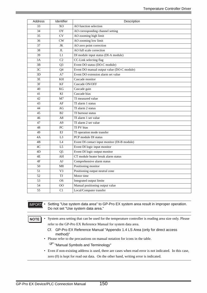
Temperature Controller Driver
GP-Pro EX Device/PLC Connection Manual 150
33 XO AO function selection34 OY AO corresponding channel setting35 CV AO zooming high limit36 CW AO zooming low limit37 JK AO zero point correction38 JL AO full scale correction39 L1 DI module input status (DI-A module)3A C2 CC-Link selecting flag3B Q3 Event DO status (DO-C module)3C Q4 Event DO manual output value (DO-C module)3D A7 Event DO extension alarm set value3E KH Cascade monitor3F KF Cascade ON/OFF40 KG Cascade gain41 KI Cascade bias42 M7 TI measured value43 AF TI alarm 1 status44 AG TI alarm 2 status45 B2 TI burnout status46 A8 TI alarm 1 set value47 A9 TI alarm 2 set value48 PC TI PV bias49 EJ TI operation mode transfer4A L3 PCP module DI status4B L4 Event DI contact input monitor (DI-B module)4C L5 Event DI logic input monitor4D Q5 Event DI logic output monitor4E AH CT module heater break alarm status4F AJ Comprehensive alarm status50 M8 Positioning monitor51 V3 Positioning output neutral zone52 TJ Motor time53 OS Integrated output limite54 OO Manual positioning output value55 C1 Local/Computer transfer
• Setting "Use system data area" to GP-Pro EX system area result in improper operation. Do not set "Use system data area."
• System area setting that can be used for the temperature controller is reading area size only. Please refer to the GP-Pro EX Reference Manual for system data area.Cf. GP-Pro EX Reference Manual "Appendix 1.4 LS Area (only for direct access
method)"• Please refer to the precautions on manual notation for icons in the table.
"Manual Symbols and Terminology"• Even if non-existing address is used, there are cases when read error is not indicated. In this case,
zero (0) is kept for read out data. On the other hand, writing error is indicated.
Address Identifier Description
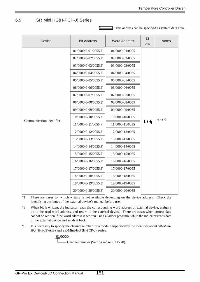
Temperature Controller Driver
GP-Pro EX Device/PLC Connection Manual 151
6.9 SR Mini HG(H-PCP-J) Series
This address can be specified as system data area.
Device Bit Address Word Address32bits
Notes
Communication identifier
01/0000.0-01/0055.F 01/0000-01/0055
*1 *2 *3
*1 There are cases for which writing is not available depending on the device address. Check the identifying attributes of the external device’s manual before use.
*2 When bit is written, the indicator reads the corresponding word address of external device, assign a bit to the read word address, and return to the external device. There are cases when correct data cannot be written if the word address is written using a ladder program, while the indicator reads data of the external device and sends it back.
*3 It is necessary to specify the channel number for a module supported by the identifier about SR-Mini- HG (H-PCP-A/B) and SR-Mini-HG (H-PCP-J) Series.
02/0000.0-02/0055.F 02/0000-02/0055
03/0000.0-03/0055.F 03/0000-03/0055
04/0000.0-04/0055.F 04/0000-04/0055
05/0000.0-05/0055.F 05/0000-05/0055
06/0000.0-06/0055.F 06/0000-06/0055
07/0000.0-07/0055.F 07/0000-07/0055
08/0000.0-08/0055.F 08/0000-08/0055
09/0000.0-09/0055.F 09/0000-09/0055
10/0000.0-10/0055.F 10/0000-10/0055
11/0000.0-11/0055.F 11/0000-11/0055
12/0000.0-12/0055.F 12/0000-12/0055
13/0000.0-13/0055.F 13/0000-13/0055
14/0000.0-14/0055.F 14/0000-14/0055
15/0000.0-15/0055.F 15/0000-15/0055
16/0000.0-16/0055.F 16/0000-16/0055
17/0000.0-17/0055.F 17/0000-17/0055
18/0000.0-18/0055.F 18/0000-18/0055
19/0000.0-19/0055.F 19/0000-19/0055
20/0000.0-20/0055.F 20/0000-20/0055
01/0000Channel number (Setting range: 01 to 20)
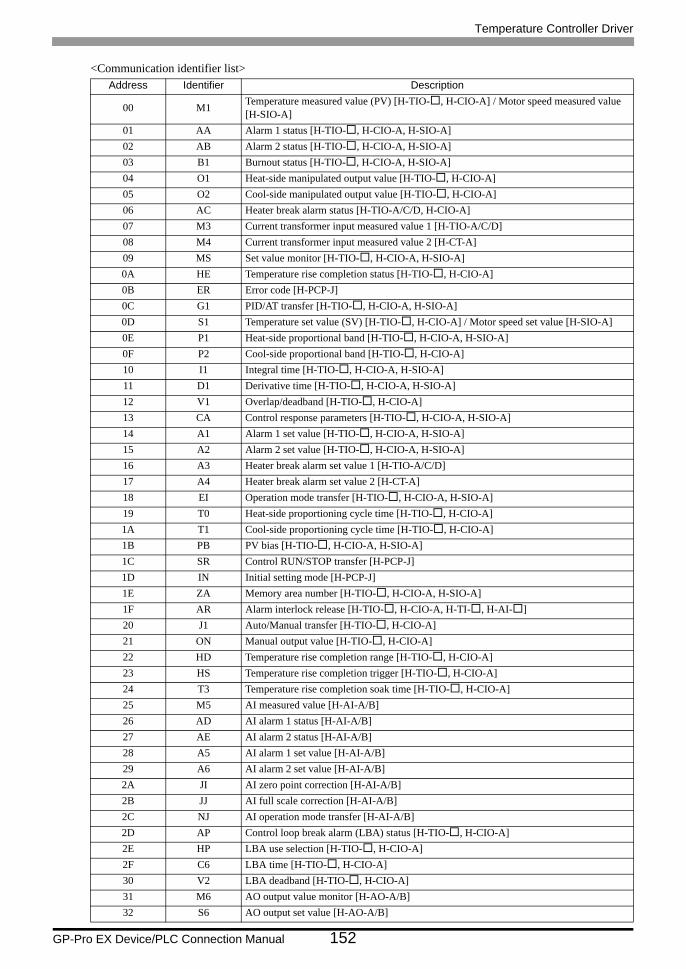
Temperature Controller Driver
GP-Pro EX Device/PLC Connection Manual 152
<Communication identifier list>Address Identifier Description
00 M1 Temperature measured value (PV) [H-TIO- , H-CIO-A] / Motor speed measured value [H-SIO-A]
01 AA Alarm 1 status [H-TIO- , H-CIO-A, H-SIO-A]02 AB Alarm 2 status [H-TIO- , H-CIO-A, H-SIO-A]03 B1 Burnout status [H-TIO- , H-CIO-A, H-SIO-A]04 O1 Heat-side manipulated output value [H-TIO- , H-CIO-A]05 O2 Cool-side manipulated output value [H-TIO- , H-CIO-A]06 AC Heater break alarm status [H-TIO-A/C/D, H-CIO-A]07 M3 Current transformer input measured value 1 [H-TIO-A/C/D]08 M4 Current transformer input measured value 2 [H-CT-A]09 MS Set value monitor [H-TIO- , H-CIO-A, H-SIO-A]0A HE Temperature rise completion status [H-TIO- , H-CIO-A]0B ER Error code [H-PCP-J]0C G1 PID/AT transfer [H-TIO- , H-CIO-A, H-SIO-A]0D S1 Temperature set value (SV) [H-TIO- , H-CIO-A] / Motor speed set value [H-SIO-A]0E P1 Heat-side proportional band [H-TIO- , H-CIO-A, H-SIO-A]0F P2 Cool-side proportional band [H-TIO- , H-CIO-A]10 I1 Integral time [H-TIO- , H-CIO-A, H-SIO-A]11 D1 Derivative time [H-TIO- , H-CIO-A, H-SIO-A]12 V1 Overlap/deadband [H-TIO- , H-CIO-A]13 CA Control response parameters [H-TIO- , H-CIO-A, H-SIO-A]14 A1 Alarm 1 set value [H-TIO- , H-CIO-A, H-SIO-A]15 A2 Alarm 2 set value [H-TIO- , H-CIO-A, H-SIO-A]16 A3 Heater break alarm set value 1 [H-TIO-A/C/D]17 A4 Heater break alarm set value 2 [H-CT-A]18 EI Operation mode transfer [H-TIO- , H-CIO-A, H-SIO-A]19 T0 Heat-side proportioning cycle time [H-TIO- , H-CIO-A]1A T1 Cool-side proportioning cycle time [H-TIO- , H-CIO-A]1B PB PV bias [H-TIO- , H-CIO-A, H-SIO-A]1C SR Control RUN/STOP transfer [H-PCP-J]1D IN Initial setting mode [H-PCP-J]1E ZA Memory area number [H-TIO- , H-CIO-A, H-SIO-A]1F AR Alarm interlock release [H-TIO- , H-CIO-A, H-TI- , H-AI- ]20 J1 Auto/Manual transfer [H-TIO- , H-CIO-A]21 ON Manual output value [H-TIO- , H-CIO-A]22 HD Temperature rise completion range [H-TIO- , H-CIO-A]23 HS Temperature rise completion trigger [H-TIO- , H-CIO-A]24 T3 Temperature rise completion soak time [H-TIO- , H-CIO-A]25 M5 AI measured value [H-AI-A/B]26 AD AI alarm 1 status [H-AI-A/B]27 AE AI alarm 2 status [H-AI-A/B]28 A5 AI alarm 1 set value [H-AI-A/B]29 A6 AI alarm 2 set value [H-AI-A/B]2A JI AI zero point correction [H-AI-A/B]2B JJ AI full scale correction [H-AI-A/B]2C NJ AI operation mode transfer [H-AI-A/B]2D AP Control loop break alarm (LBA) status [H-TIO- , H-CIO-A]2E HP LBA use selection [H-TIO- , H-CIO-A]2F C6 LBA time [H-TIO- , H-CIO-A]30 V2 LBA deadband [H-TIO- , H-CIO-A]31 M6 AO output value monitor [H-AO-A/B]32 S6 AO output set value [H-AO-A/B]
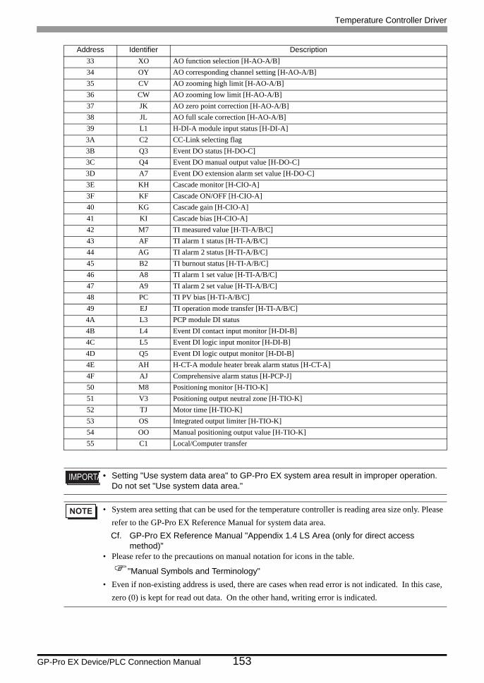
Temperature Controller Driver
GP-Pro EX Device/PLC Connection Manual 153
33 XO AO function selection [H-AO-A/B]34 OY AO corresponding channel setting [H-AO-A/B]35 CV AO zooming high limit [H-AO-A/B]36 CW AO zooming low limit [H-AO-A/B]37 JK AO zero point correction [H-AO-A/B]38 JL AO full scale correction [H-AO-A/B]39 L1 H-DI-A module input status [H-DI-A]3A C2 CC-Link selecting flag3B Q3 Event DO status [H-DO-C]3C Q4 Event DO manual output value [H-DO-C]3D A7 Event DO extension alarm set value [H-DO-C]3E KH Cascade monitor [H-CIO-A]3F KF Cascade ON/OFF [H-CIO-A]40 KG Cascade gain [H-CIO-A]41 KI Cascade bias [H-CIO-A]42 M7 TI measured value [H-TI-A/B/C]43 AF TI alarm 1 status [H-TI-A/B/C]44 AG TI alarm 2 status [H-TI-A/B/C]45 B2 TI burnout status [H-TI-A/B/C]46 A8 TI alarm 1 set value [H-TI-A/B/C]47 A9 TI alarm 2 set value [H-TI-A/B/C]48 PC TI PV bias [H-TI-A/B/C]49 EJ TI operation mode transfer [H-TI-A/B/C]4A L3 PCP module DI status4B L4 Event DI contact input monitor [H-DI-B]4C L5 Event DI logic input monitor [H-DI-B]4D Q5 Event DI logic output monitor [H-DI-B]4E AH H-CT-A module heater break alarm status [H-CT-A]4F AJ Comprehensive alarm status [H-PCP-J]50 M8 Positioning monitor [H-TIO-K]51 V3 Positioning output neutral zone [H-TIO-K]52 TJ Motor time [H-TIO-K]53 OS Integrated output limiter [H-TIO-K]54 OO Manual positioning output value [H-TIO-K]55 C1 Local/Computer transfer
• Setting "Use system data area" to GP-Pro EX system area result in improper operation. Do not set "Use system data area."
• System area setting that can be used for the temperature controller is reading area size only. Please refer to the GP-Pro EX Reference Manual for system data area.Cf. GP-Pro EX Reference Manual "Appendix 1.4 LS Area (only for direct access
method)"• Please refer to the precautions on manual notation for icons in the table.
"Manual Symbols and Terminology"• Even if non-existing address is used, there are cases when read error is not indicated. In this case,
zero (0) is kept for read out data. On the other hand, writing error is indicated.
Address Identifier Description
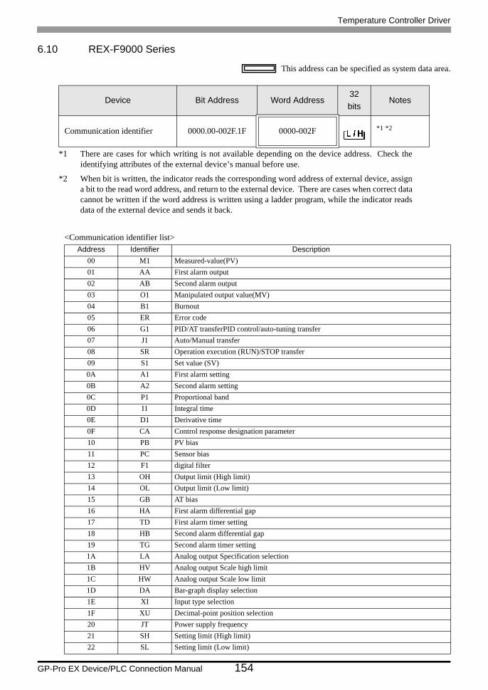
Temperature Controller Driver
GP-Pro EX Device/PLC Connection Manual 154
6.10 REX-F9000 Series
This address can be specified as system data area.
<Communication identifier list>
Device Bit Address Word Address32bits
Notes
Communication identifier 0000.00-002F.1F 0000-002F *1 *2
*1 There are cases for which writing is not available depending on the device address. Check the identifying attributes of the external device’s manual before use.
*2 When bit is written, the indicator reads the corresponding word address of external device, assign a bit to the read word address, and return to the external device. There are cases when correct data cannot be written if the word address is written using a ladder program, while the indicator reads data of the external device and sends it back.
Address Identifier Description00 M1 Measured-value(PV)01 AA First alarm output02 AB Second alarm output03 O1 Manipulated output value(MV)04 B1 Burnout05 ER Error code06 G1 PID/AT transferPID control/auto-tuning transfer07 J1 Auto/Manual transfer08 SR Operation execution (RUN)/STOP transfer09 S1 Set value (SV)0A A1 First alarm setting0B A2 Second alarm setting0C P1 Proportional band0D I1 Integral time0E D1 Derivative time0F CA Control response designation parameter10 PB PV bias11 PC Sensor bias12 F1 digital filter13 OH Output limit (High limit)14 OL Output limit (Low limit)15 GB AT bias16 HA First alarm differential gap17 TD First alarm timer setting18 HB Second alarm differential gap19 TG Second alarm timer setting1A LA Analog output Specification selection1B HV Analog output Scale high limit1C HW Analog output Scale low limit1D DA Bar-graph display selection1E XI Input type selection1F XU Decimal-point position selection20 JT Power supply frequency21 SH Setting limit (High limit)22 SL Setting limit (Low limit)
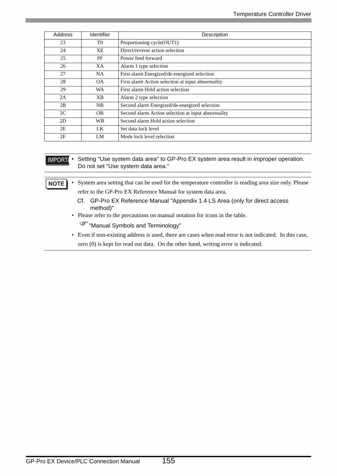
Temperature Controller Driver
GP-Pro EX Device/PLC Connection Manual 155
23 T0 Proportioning cycle(OUT1)24 XE Direct/reverse action selection25 PF Power feed forward26 XA Alarm 1 type selection27 NA First alarm Energized/de-energized selection28 OA First alarm Action selection at input abnormality29 WA First alarm Hold action selection2A XB Alarm 2 type selection2B NB Second alarm Energized/de-energized selection2C OB Second alarm Action selection at input abnormality2D WB Second alarm Hold action selection2E LK Set data lock level2F LM Mode lock level selection
• Setting "Use system data area" to GP-Pro EX system area result in improper operation. Do not set "Use system data area."
• System area setting that can be used for the temperature controller is reading area size only. Please refer to the GP-Pro EX Reference Manual for system data area.Cf. GP-Pro EX Reference Manual "Appendix 1.4 LS Area (only for direct access
method)"• Please refer to the precautions on manual notation for icons in the table.
"Manual Symbols and Terminology"• Even if non-existing address is used, there are cases when read error is not indicated. In this case,
zero (0) is kept for read out data. On the other hand, writing error is indicated.
Address Identifier Description
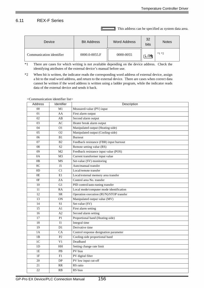
Temperature Controller Driver
GP-Pro EX Device/PLC Connection Manual 156
6.11 REX-F Series
This address can be specified as system data area.
<Communication identifier list>
Device Bit Address Word Address32bits
Notes
Communication identifier 0000.0-0055.F 0000-0055 *1 *2
*1 There are cases for which writing is not available depending on the device address. Check the identifying attributes of the external device’s manual before use.
*2 When bit is written, the indicator reads the corresponding word address of external device, assign a bit to the read word address, and return to the external device. There are cases when correct data cannot be written if the word address is written using a ladder program, while the indicator reads data of the external device and sends it back.
Address Identifier Description00 M1 Measured-value (PV) input01 AA First alarm output02 AB Second alarm output03 AC Heater break alarm output04 O1 Manipulated output (Heating-side)05 O2 Manipulated output (Cooling-side)06 B1 Burnout07 B2 Feedback resistance (FBR) input burnout08 S2 Remote setting value (RS)09 M2 Feedback resistance input value (POS)0A M3 Current transformer input value0B MS Set-value (SV) monitoring0C J1 Auto/manual transfer0D C1 Local/remote transfer0E E1 Local/external memory area transfer0F ZA Control area No. transfer10 G1 PID control/auto-tuning transfer11 RA Local mode/computer mode identification12 SR Operation execution (RUN)/STOP transfer13 ON Manipulated output value (MV)14 S1 Set-value (SV)15 A1 First alarm setting16 A2 Second alarm setting17 P1 Proportional band (Heating-side)18 I1 Integral time19 D1 Derivative time1A CA Control response designation parameter1B P2 Cooling-side proportional band1C V1 Deadband1D HH Setting change rate limit1E PB PV bias1F F1 PV digital filter20 DP PV low input cut-off21 RR RS ratio22 RB RS bias
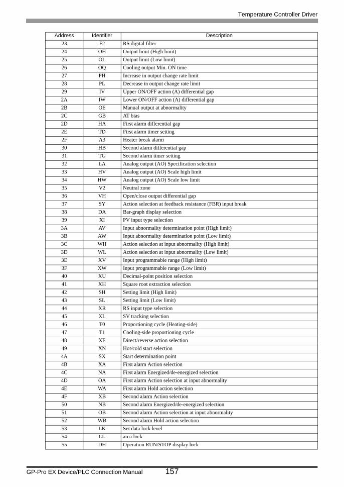
Temperature Controller Driver
GP-Pro EX Device/PLC Connection Manual 157
23 F2 RS digital filter24 OH Output limit (High limit)25 OL Output limit (Low limit)26 OQ Cooling output Min. ON time27 PH Increase in output change rate limit28 PL Decrease in output change rate limit29 IV Upper ON/OFF action (A) differential gap2A IW Lower ON/OFF action (A) differential gap2B OE Manual output at abnormality2C GB AT bias2D HA First alarm differential gap2E TD First alarm timer setting2F A3 Heater break alarm30 HB Second alarm differential gap31 TG Second alarm timer setting32 LA Analog output (AO) Specification selection33 HV Analog output (AO) Scale high limit34 HW Analog output (AO) Scale low limit35 V2 Neutral zone36 VH Open/close output differential gap37 SY Action selection at feedback resistance (FBR) input break38 DA Bar-graph display selection39 XI PV input type selection3A AV Input abnormality determination point (High limit)3B AW Input abnormality determination point (Low limit)3C WH Action selection at input abnormality (High limit)3D WL Action selection at input abnormality (Low limit)3E XV Input programmable range (High limit)3F XW Input programmable range (Low limit)40 XU Decimal-point position selection41 XH Square root extraction selection42 SH Setting limit (High limit)43 SL Setting limit (Low limit)44 XR RS input type selection45 XL SV tracking selection46 T0 Proportioning cycle (Heating-side)47 T1 Cooling-side proportioning cycle48 XE Direct/reverse action selection49 XN Hot/cold start selection4A SX Start determination point4B XA First alarm Action selection4C NA First alarm Energized/de-energized selection4D OA First alarm Action selection at input abnormality4E WA First alarm Hold action selection4F XB Second alarm Action selection50 NB Second alarm Energized/de-energized selection51 OB Second alarm Action selection at input abnormality52 WB Second alarm Hold action selection53 LK Set data lock level54 LL area lock55 DH Operation RUN/STOP display lock
Address Identifier Description
Temperature Controller Driver
GP-Pro EX Device/PLC Connection Manual 158
• Setting "Use system data area" to GP-Pro EX system area result in improper operation. Do not set "Use system data area."
• System area setting that can be used for the temperature controller is reading area size only. Please refer to the GP-Pro EX Reference Manual for system data area.Cf. GP-Pro EX Reference Manual "Appendix 1.4 LS Area (only for direct access
method)"• Please refer to the precautions on manual notation for icons in the table.
"Manual Symbols and Terminology"• Even if non-existing address is used, there are cases when read error is not indicated. In this case,
zero (0) is kept for read out data. On the other hand, writing error is indicated.
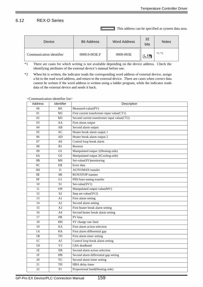
Temperature Controller Driver
GP-Pro EX Device/PLC Connection Manual 159
6.12 REX-D Series
This address can be specified as system data area.
<Communication identifier list>
Device Bit Address Word Address32bits
Notes
Communication identifier 0000.0-003E.F 0000-003E *1 *2
*1 There are cases for which writing is not available depending on the device address. Check the identifying attributes of the external device’s manual before use.
*2 When bit is written, the indicator reads the corresponding word address of external device, assign a bit to the read word address, and return to the external device. There are cases when correct data cannot be written if the word address is written using a ladder program, while the indicator reads data of the external device and sends it back.
Address Identifier Description00 M1 Measured-value(PV)01 M2 First current transformer input value(CT1)02 M3 Second current transformer input value(CT2)03 AA First alarm output04 AB Second alarm output05 AC Heater break alarm output 106 AD Heater break alarm output 207 AE Control loop break alarm08 B1 Burnout09 O1 Manipulated output 1(Heating-side)0A O2 Manipulated output 2(Cooling-side)0B MS Set-value(SV)monitoring0C ER Error data0D J1 AUTO/MAN transfer0E SR RUN/STOP transter0F G1 PID/Auto-tuning transfer10 S1 Set-value(SV1)11 ON Manipulated output value(MV)12 S2 Step set-value(SV2)13 A1 First alarm setting14 A2 Second alarm setting15 A3 First heater break alarm setting16 A4 Second heater break alarm setting17 PB PV bias18 HH SV change rate limit19 XA First alarm action selection1A HA First alarm differential gap1B TD First alarm timer setting1C A5 Control loop break alarm setting1D V3 LBA deadband1E XB Second alarm action selection1F HB Second alarm differential gap setting20 TG Second alarm timer setting21 TH HBA delay timer22 P1 Proportional band(Heating-side)
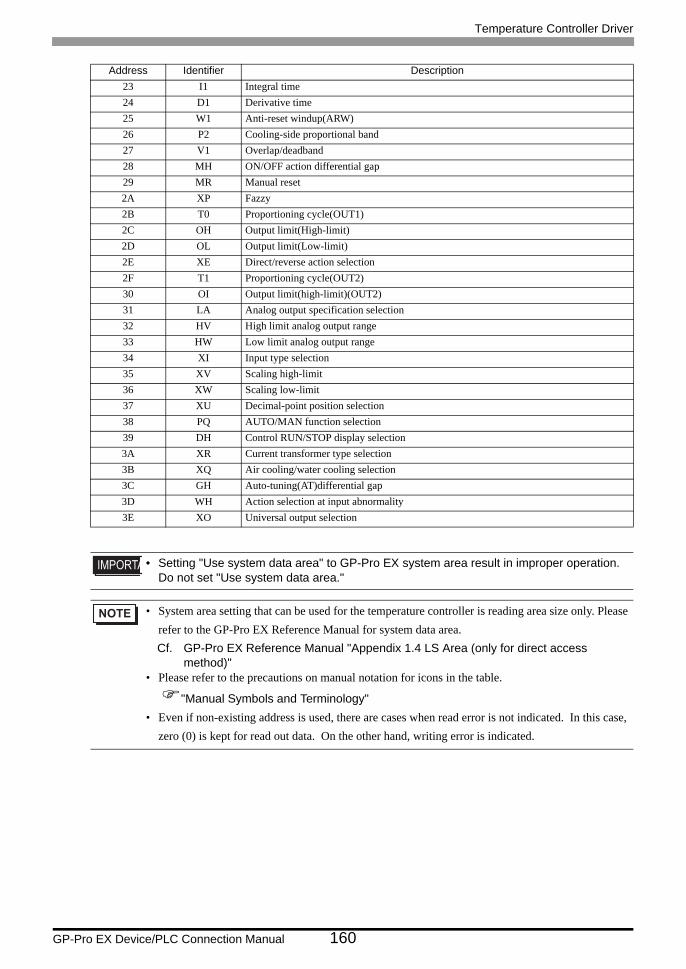
Temperature Controller Driver
GP-Pro EX Device/PLC Connection Manual 160
23 I1 Integral time24 D1 Derivative time25 W1 Anti-reset windup(ARW)26 P2 Cooling-side proportional band27 V1 Overlap/deadband28 MH ON/OFF action differential gap29 MR Manual reset2A XP Fazzy2B T0 Proportioning cycle(OUT1)2C OH Output limit(High-limit)2D OL Output limit(Low-limit)2E XE Direct/reverse action selection2F T1 Proportioning cycle(OUT2)30 OI Output limit(high-limit)(OUT2)31 LA Analog output specification selection32 HV High limit analog output range33 HW Low limit analog output range34 XI Input type selection35 XV Scaling high-limit36 XW Scaling low-limit37 XU Decimal-point position selection38 PQ AUTO/MAN function selection39 DH Control RUN/STOP display selection3A XR Current transformer type selection3B XQ Air cooling/water cooling selection3C GH Auto-tuning(AT)differential gap3D WH Action selection at input abnormality3E XO Universal output selection
• Setting "Use system data area" to GP-Pro EX system area result in improper operation. Do not set "Use system data area."
• System area setting that can be used for the temperature controller is reading area size only. Please refer to the GP-Pro EX Reference Manual for system data area.Cf. GP-Pro EX Reference Manual "Appendix 1.4 LS Area (only for direct access
method)"• Please refer to the precautions on manual notation for icons in the table.
"Manual Symbols and Terminology"• Even if non-existing address is used, there are cases when read error is not indicated. In this case,
zero (0) is kept for read out data. On the other hand, writing error is indicated.
Address Identifier Description
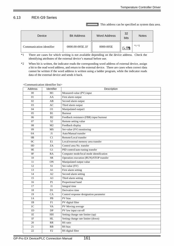
Temperature Controller Driver
GP-Pro EX Device/PLC Connection Manual 161
6.13 REX-G9 Series
This address can be specified as system data area.
<Communication identifier list>
Device Bit Address Word Address32bits
Notes
Communication identifier 0000.00-005E.1F 0000-005E *1 *2
*1 There are cases for which writing is not available depending on the device address. Check the identifying attributes of the external device’s manual before use.
*2 When bit is written, the indicator reads the corresponding word address of external device, assign a bit to the read word address, and return to the external device. There are cases when correct data cannot be written if the word address is written using a ladder program, while the indicator reads data of the external device and sends it back.
Address Identifier Description00 M1 Measured-value (PV) input01 AA First alarm output02 AB Second alarm output03 AC Third alarm output04 O1 Manipulated output105 B1 Burnout06 B2 Feedback resistance (FBR) input burnout07 S2 Remote setting value08 M2 Feedback display09 MS Set-value (SV) monitoring0A J1 Auto/Manual transfer0B C1 Remote/Local transfer0C E1 Local/external memory area transfer0D ZA Control area No. transfer0E G1 PID control/auto-tuning transfer0F RA Computer mode/local mode identification10 SR Operation execution (RUN)/STOP transfer11 ON Manipulated output value12 S1 Set-value (SV)13 A1 First alarm setting14 A2 Second alarm setting15 A3 Third alarm setting16 P1 Proportional band17 I1 Integral time18 D1 Derivative time19 CA Control response designation parameter1A PB PV bias1B F1 PV digital filter1C VA PV Moving average1D DP PV low input cut-off1E HH Setting change rate limiter (up)1F HL Setting change rate limiter (down)20 RR RS ratio21 RB RS bias22 F2 RS digital filter
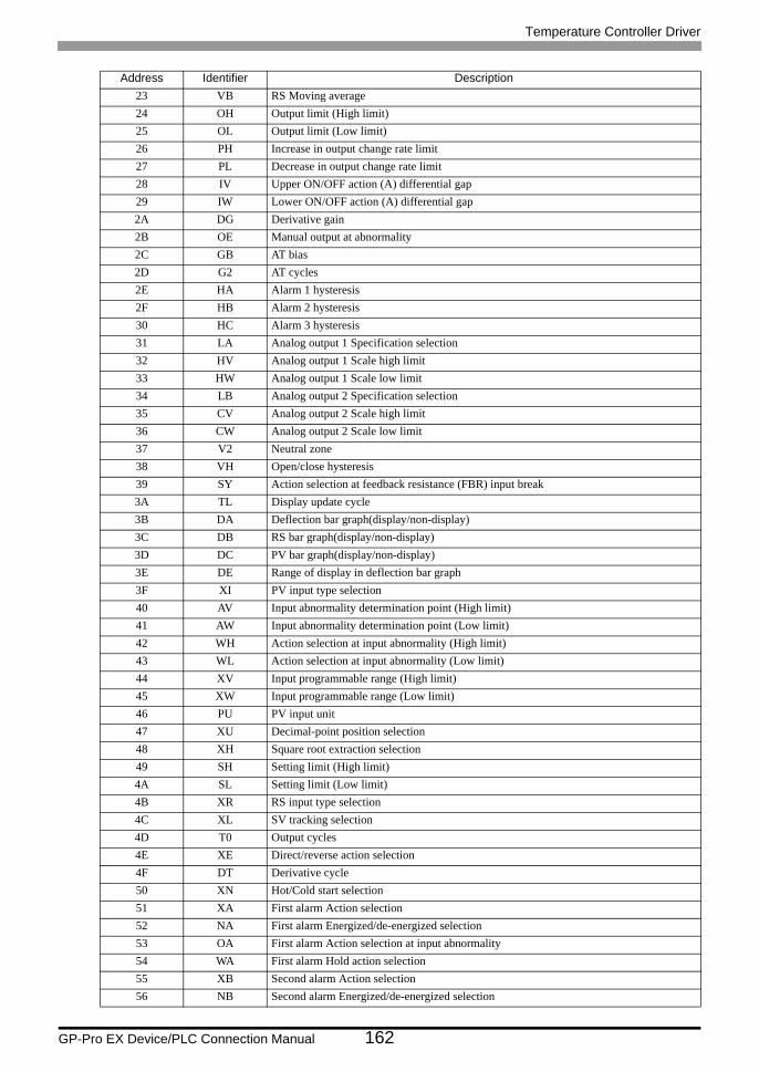
Temperature Controller Driver
GP-Pro EX Device/PLC Connection Manual 162
23 VB RS Moving average24 OH Output limit (High limit)25 OL Output limit (Low limit)26 PH Increase in output change rate limit27 PL Decrease in output change rate limit28 IV Upper ON/OFF action (A) differential gap29 IW Lower ON/OFF action (A) differential gap2A DG Derivative gain2B OE Manual output at abnormality2C GB AT bias2D G2 AT cycles2E HA Alarm 1 hysteresis2F HB Alarm 2 hysteresis30 HC Alarm 3 hysteresis31 LA Analog output 1 Specification selection32 HV Analog output 1 Scale high limit33 HW Analog output 1 Scale low limit34 LB Analog output 2 Specification selection35 CV Analog output 2 Scale high limit36 CW Analog output 2 Scale low limit37 V2 Neutral zone38 VH Open/close hysteresis39 SY Action selection at feedback resistance (FBR) input break3A TL Display update cycle3B DA Deflection bar graph(display/non-display)3C DB RS bar graph(display/non-display)3D DC PV bar graph(display/non-display)3E DE Range of display in deflection bar graph3F XI PV input type selection40 AV Input abnormality determination point (High limit)41 AW Input abnormality determination point (Low limit)42 WH Action selection at input abnormality (High limit)43 WL Action selection at input abnormality (Low limit)44 XV Input programmable range (High limit)45 XW Input programmable range (Low limit)46 PU PV input unit47 XU Decimal-point position selection48 XH Square root extraction selection49 SH Setting limit (High limit)4A SL Setting limit (Low limit)4B XR RS input type selection4C XL SV tracking selection4D T0 Output cycles4E XE Direct/reverse action selection4F DT Derivative cycle50 XN Hot/Cold start selection51 XA First alarm Action selection52 NA First alarm Energized/de-energized selection53 OA First alarm Action selection at input abnormality54 WA First alarm Hold action selection55 XB Second alarm Action selection56 NB Second alarm Energized/de-energized selection
Address Identifier Description
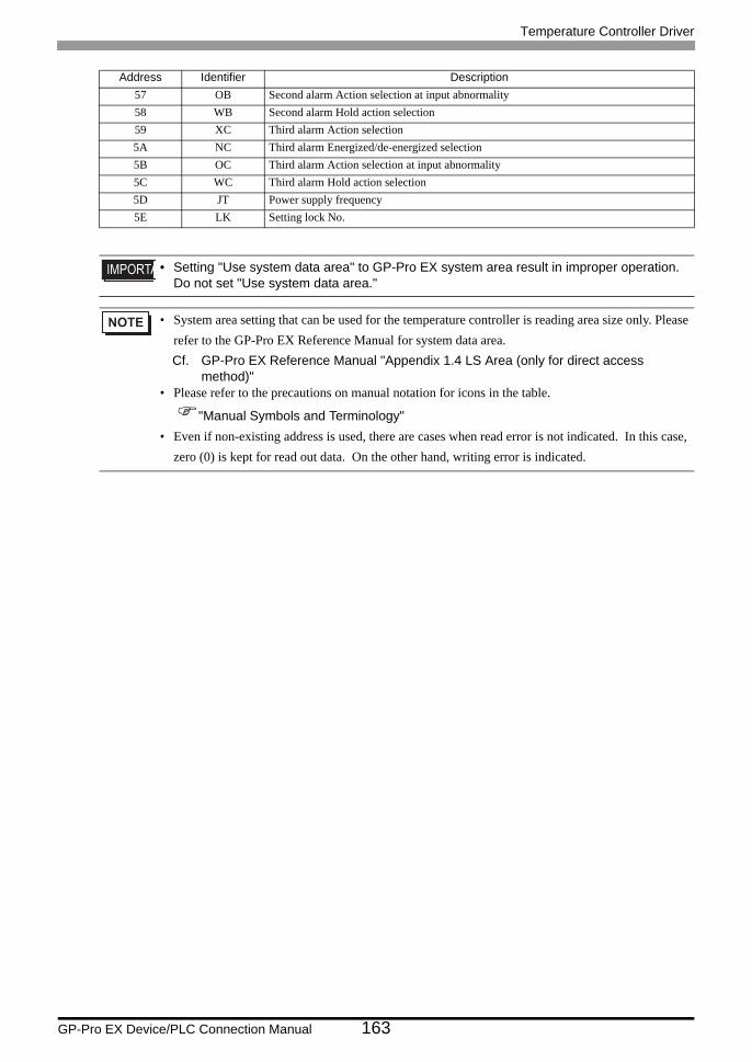
Temperature Controller Driver
GP-Pro EX Device/PLC Connection Manual 163
57 OB Second alarm Action selection at input abnormality58 WB Second alarm Hold action selection59 XC Third alarm Action selection5A NC Third alarm Energized/de-energized selection5B OC Third alarm Action selection at input abnormality5C WC Third alarm Hold action selection5D JT Power supply frequency5E LK Setting lock No.
• Setting "Use system data area" to GP-Pro EX system area result in improper operation. Do not set "Use system data area."
• System area setting that can be used for the temperature controller is reading area size only. Please refer to the GP-Pro EX Reference Manual for system data area.Cf. GP-Pro EX Reference Manual "Appendix 1.4 LS Area (only for direct access
method)"• Please refer to the precautions on manual notation for icons in the table.
"Manual Symbols and Terminology"• Even if non-existing address is used, there are cases when read error is not indicated. In this case,
zero (0) is kept for read out data. On the other hand, writing error is indicated.
Address Identifier Description
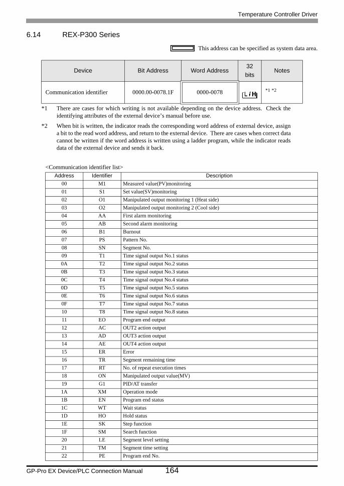
Temperature Controller Driver
GP-Pro EX Device/PLC Connection Manual 164
6.14 REX-P300 Series
This address can be specified as system data area.
<Communication identifier list>
Device Bit Address Word Address32bits
Notes
Communication identifier 0000.00-0078.1F 0000-0078 *1 *2
*1 There are cases for which writing is not available depending on the device address. Check the identifying attributes of the external device’s manual before use.
*2 When bit is written, the indicator reads the corresponding word address of external device, assign a bit to the read word address, and return to the external device. There are cases when correct data cannot be written if the word address is written using a ladder program, while the indicator reads data of the external device and sends it back.
Address Identifier Description00 M1 Measured value(PV)monitoring01 S1 Set value(SV)monitoring02 O1 Manipulated output monitoring 1 (Heat side)03 O2 Manipulated output monitoring 2 (Cool side)04 AA First alarm monitoring05 AB Second alarm monitoring06 B1 Burnout07 PS Pattern No.08 SN Segment No.09 T1 Time signal output No.1 status0A T2 Time signal output No.2 status0B T3 Time signal output No.3 status0C T4 Time signal output No.4 status0D T5 Time signal output No.5 status0E T6 Time signal output No.6 status0F T7 Time signal output No.7 status10 T8 Time signal output No.8 status11 EO Program end output12 AC OUT2 action output13 AD OUT3 action output14 AE OUT4 action output15 ER Error16 TR Segment remaining time17 RT No. of repeat execution times18 ON Manipulated output value(MV)19 G1 PID/AT transfer1A XM Operation mode1B EN Program end status1C WT Wait status1D HO Hold status1E SK Step function1F SM Search function20 LE Segment level setting21 TM Segment time setting22 PE Program end No.
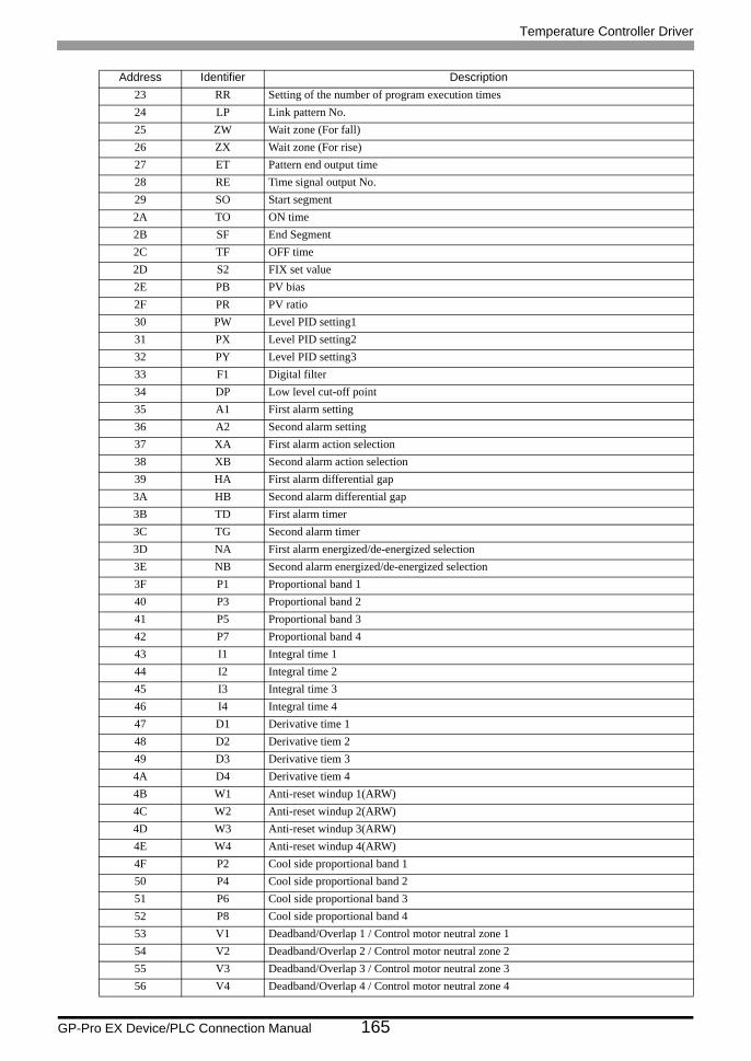
Temperature Controller Driver
GP-Pro EX Device/PLC Connection Manual 165
23 RR Setting of the number of program execution times24 LP Link pattern No.25 ZW Wait zone (For fall)26 ZX Wait zone (For rise)27 ET Pattern end output time28 RE Time signal output No.29 SO Start segment2A TO ON time2B SF End Segment2C TF OFF time2D S2 FIX set value2E PB PV bias2F PR PV ratio30 PW Level PID setting131 PX Level PID setting232 PY Level PID setting333 F1 Digital filter34 DP Low level cut-off point35 A1 First alarm setting36 A2 Second alarm setting37 XA First alarm action selection38 XB Second alarm action selection39 HA First alarm differential gap3A HB Second alarm differential gap3B TD First alarm timer3C TG Second alarm timer3D NA First alarm energized/de-energized selection3E NB Second alarm energized/de-energized selection3F P1 Proportional band 140 P3 Proportional band 241 P5 Proportional band 342 P7 Proportional band 443 I1 Integral time 144 I2 Integral time 245 I3 Integral time 346 I4 Integral time 447 D1 Derivative time 148 D2 Derivative tiem 249 D3 Derivative tiem 34A D4 Derivative tiem 44B W1 Anti-reset windup 1(ARW)4C W2 Anti-reset windup 2(ARW)4D W3 Anti-reset windup 3(ARW)4E W4 Anti-reset windup 4(ARW)4F P2 Cool side proportional band 150 P4 Cool side proportional band 251 P6 Cool side proportional band 352 P8 Cool side proportional band 453 V1 Deadband/Overlap 1 / Control motor neutral zone 154 V2 Deadband/Overlap 2 / Control motor neutral zone 255 V3 Deadband/Overlap 3 / Control motor neutral zone 356 V4 Deadband/Overlap 4 / Control motor neutral zone 4
Address Identifier Description
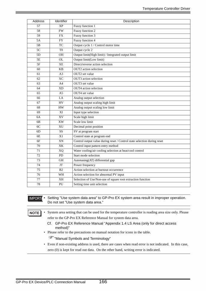
Temperature Controller Driver
GP-Pro EX Device/PLC Connection Manual 166
57 XP Fuzzy function 158 FW Fuzzy function 259 FX Fuzzy function 35A FY Fuzzy function 45B TC Output cycle 1 / Control motor time5C T0 Output cycle 25D OH Output limit(High limit) / Integrated output limit5E OL Output limit(Low limit)5F XE Direct/reverse action selection60 KB OUT2 action selection61 A3 OUT2 set value62 XC OUT3 action selection63 A4 OUT3 set value64 XD OUT4 action selection65 A5 OUT4 set value66 LA Analog output selection67 HV Analog output scaling high limit68 HW Analog output scaling low limit69 XI Input type selection6A XV Scale high limit6B XW Scale low limit6C XU Decimal point position6D SS SV at program start6E X1 Control state at program end6F XN Control output value during reset / Control state selection during reset70 XK Control input pattern entry method71 XQ Water cooling/air cooling selection at heat/cool control72 PD Start mode selection73 GH Autotuning(AT) differential gap74 JT Power frequency75 B2 Action selection at burnout occurrence76 WH Action selection for abnormal PV input77 XH Selection of Use/Non-use of square root extraction function78 PU Setting time unit selection
• Setting "Use system data area" to GP-Pro EX system area result in improper operation. Do not set "Use system data area."
• System area setting that can be used for the temperature controller is reading area size only. Please refer to the GP-Pro EX Reference Manual for system data area.Cf. GP-Pro EX Reference Manual "Appendix 1.4 LS Area (only for direct access
method)"• Please refer to the precautions on manual notation for icons in the table.
"Manual Symbols and Terminology"• Even if non-existing address is used, there are cases when read error is not indicated. In this case,
zero (0) is kept for read out data. On the other hand, writing error is indicated.
Address Identifier Description
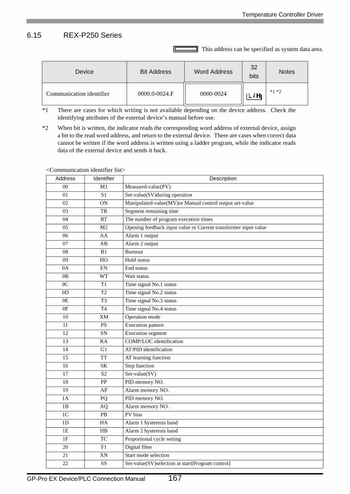
Temperature Controller Driver
GP-Pro EX Device/PLC Connection Manual 167
6.15 REX-P250 Series
This address can be specified as system data area.
<Communication identifier list>
Device Bit Address Word Address32bits
Notes
Communication identifier 0000.0-0024.F 0000-0024 *1 *2
*1 There are cases for which writing is not available depending on the device address. Check the identifying attributes of the external device’s manual before use.
*2 When bit is written, the indicator reads the corresponding word address of external device, assign a bit to the read word address, and return to the external device. There are cases when correct data cannot be written if the word address is written using a ladder program, while the indicator reads data of the external device and sends it back.
Address Identifier Description00 M1 Measured-value(PV)01 S1 Set-value(SV)during operation02 ON Manipulated-value(MV)or Manual control output set-value03 TR Segment remaining time04 RT The number of program execution times05 M2 Opening feedback input value or Current transformer input value06 AA Alarm 1 output07 AB Alarm 2 output08 B1 Burnout09 HO Hold status0A EN End status0B WT Wait status0C T1 Time signal No.1 status0D T2 Time signal No.2 status0E T3 Time signal No.3 status0F T4 Time signal No.4 status10 XM Operation mode11 PS Execution pattern12 SN Execution segment13 RA COMP/LOC identification14 G1 AT/PID identification15 TT AT learning function16 SK Step function17 S2 Set-value(SV)18 PP PID memory NO.19 AP Alarm memory NO.1A PQ PID memory NO.1B AQ Alarm memory NO.1C PB PV bias1D HA Alarm 1 hysteresis band1E HB Alarm 2 hysteresis band1F TC Proportional cycle setting20 F1 Digital filter21 XN Start mode selection22 SS Set-value(SV)selection at start[Program control]
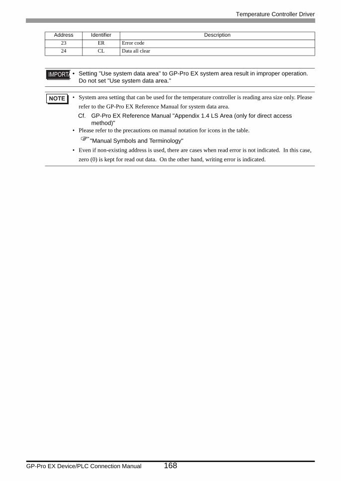
Temperature Controller Driver
GP-Pro EX Device/PLC Connection Manual 168
23 ER Error code24 CL Data all clear
• Setting "Use system data area" to GP-Pro EX system area result in improper operation. Do not set "Use system data area."
• System area setting that can be used for the temperature controller is reading area size only. Please refer to the GP-Pro EX Reference Manual for system data area.Cf. GP-Pro EX Reference Manual "Appendix 1.4 LS Area (only for direct access
method)"• Please refer to the precautions on manual notation for icons in the table.
"Manual Symbols and Terminology"• Even if non-existing address is used, there are cases when read error is not indicated. In this case,
zero (0) is kept for read out data. On the other hand, writing error is indicated.
Address Identifier Description
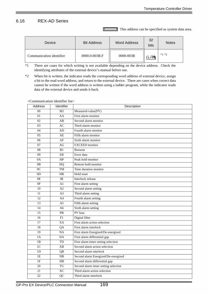
Temperature Controller Driver
GP-Pro EX Device/PLC Connection Manual 169
6.16 REX-AD Series
This address can be specified as system data area.
<Communication identifier list>
Device Bit Address Word Address32bits
Notes
Communication identifier 0000.0-003B.F 0000-003B *1 *2
*1 There are cases for which writing is not available depending on the device address. Check the identifying attributes of the external device’s manual before use.
*2 When bit is written, the indicator reads the corresponding word address of external device, assign a bit to the read word address, and return to the external device. There are cases when correct data cannot be written if the word address is written using a ladder program, while the indicator reads data of the external device and sends it back.
Address Identifier Description00 M1 Measured-value(PV)01 AA First alarm monitor02 AB Second alarm monitor03 AC Third alarm monitor04 AD Fourth alarm monitor05 AE Fifth alarm monitor06 AF Sixth alarm monitor07 AG EXCEED monitor08 B1 Burnout09 ER Error data0A HP Peak hold monitor0B HQ Bottom hold monitor0C TM Time duration monitor0D HR Hold reset0E IR Interlock release0F A1 First alarm setting10 A2 Second alarm setting11 A3 Third alarm setting12 A4 Fourth alarm setting13 A5 Fifth alarm setting14 A6 Sixth alarm setting15 PB PV bias16 F1 Digital filter17 XA First alarm action selection18 QA First alarm interlock19 NA First alarm Energized/De-energized1A HA First alarm differential gap1B TD First alarm timer setting selection1C XB Second alarm action selection1D QB Second alarm interlock1E NB Second alarm Energized/De-energized1F HB Second alarm differential gap20 TG Second alarm timer setting selection21 XC Third alarm action selection22 QC Third alarm interlock
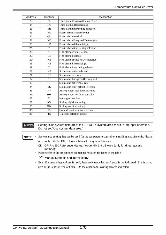
Temperature Controller Driver
GP-Pro EX Device/PLC Connection Manual 170
23 NC Third alarm Energized/De-energized24 HC Third alarm differential gap25 TH Third alarm timer setting selection26 XD Fourth alarm action selection27 QD Fourth alarm interlock28 ND Fourth alarm Energized/De-energized29 HD Fourth alarm differential gap2A TI Fourth alarm timer setting selection2B XE Fifth alarm action selection2C QE Fifth alarm interlock2D NE Fifth alarm Energized/De-energized2E HE Fifth alarm differential gap2F TJ Fifth alarm timer setting selection30 XF Sixth alarm action selection31 QF Sixth alarm interlock32 NF Sixth alarm Energized/De-energized33 HF Sixth alarm differential gap34 TK Sixth alarm timer setting selection35 HV Analog output high-limit set-value36 HW Analog output low-limit set-value37 XI Input type selection38 XV Scaling high-limit setting39 XW Scaling low-limit setting3A XU Decimal point position selection3B TS Time unit selection setting
• Setting "Use system data area" to GP-Pro EX system area result in improper operation. Do not set "Use system data area."
• System area setting that can be used for the temperature controller is reading area size only. Please refer to the GP-Pro EX Reference Manual for system data area.Cf. GP-Pro EX Reference Manual "Appendix 1.4 LS Area (only for direct access
method)"• Please refer to the precautions on manual notation for icons in the table.
"Manual Symbols and Terminology"• Even if non-existing address is used, there are cases when read error is not indicated. In this case,
zero (0) is kept for read out data. On the other hand, writing error is indicated.
Address Identifier Description
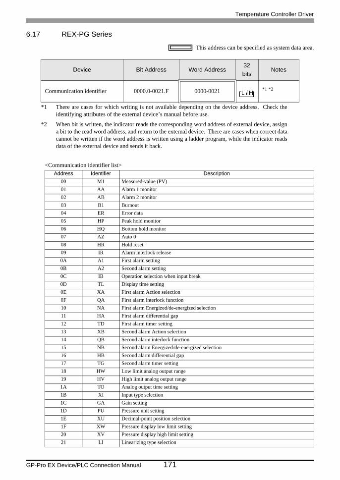
Temperature Controller Driver
GP-Pro EX Device/PLC Connection Manual 171
6.17 REX-PG Series
This address can be specified as system data area.
<Communication identifier list>
Device Bit Address Word Address32bits
Notes
Communication identifier 0000.0-0021.F 0000-0021 *1 *2
*1 There are cases for which writing is not available depending on the device address. Check the identifying attributes of the external device’s manual before use.
*2 When bit is written, the indicator reads the corresponding word address of external device, assign a bit to the read word address, and return to the external device. There are cases when correct data cannot be written if the word address is written using a ladder program, while the indicator reads data of the external device and sends it back.
Address Identifier Description00 M1 Measured-value (PV)01 AA Alarm 1 monitor02 AB Alarm 2 monitor03 B1 Burnout04 ER Error data05 HP Peak hold monitor06 HQ Bottom hold monitor07 AZ Auto 008 HR Hold reset09 IR Alarm interlock release0A A1 First alarm setting0B A2 Second alarm setting0C IB Operation selection when input break0D TL Display time setting0E XA First alarm Action selection0F QA First alarm interlock function10 NA First alarm Energized/de-energized selection11 HA First alarm differential gap12 TD First alarm timer setting13 XB Second alarm Action selection14 QB Second alarm interlock function15 NB Second alarm Energized/de-energized selection16 HB Second alarm differential gap17 TG Second alarm timer setting18 HW Low limit analog output range19 HV High limit analog output range1A TO Analog output time setting1B XI Input type selection1C GA Gain setting1D PU Pressure unit setting1E XU Decimal-point position selection1F XW Pressure display low limit setting20 XV Pressure display high limit setting21 LI Linearizing type selection

Temperature Controller Driver
GP-Pro EX Device/PLC Connection Manual 172
• Setting "Use system data area" to GP-Pro EX system area result in improper operation. Do not set "Use system data area."
• System area setting that can be used for the temperature controller is reading area size only. Please refer to the GP-Pro EX Reference Manual for system data area.Cf. GP-Pro EX Reference Manual "Appendix 1.4 LS Area (only for direct access
method)"• Please refer to the precautions on manual notation for icons in the table.
"Manual Symbols and Terminology"• Even if non-existing address is used, there are cases when read error is not indicated. In this case,
zero (0) is kept for read out data. On the other hand, writing error is indicated.
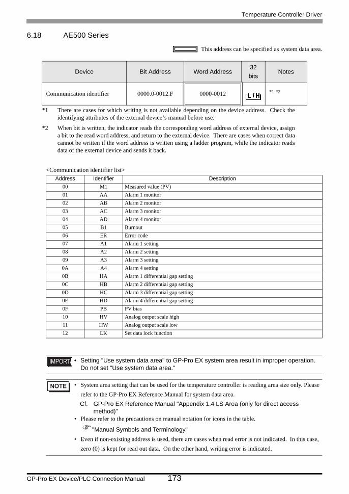
Temperature Controller Driver
GP-Pro EX Device/PLC Connection Manual 173
6.18 AE500 Series
This address can be specified as system data area.
<Communication identifier list>
Device Bit Address Word Address32bits
Notes
Communication identifier 0000.0-0012.F 0000-0012 *1 *2
*1 There are cases for which writing is not available depending on the device address. Check the identifying attributes of the external device’s manual before use.
*2 When bit is written, the indicator reads the corresponding word address of external device, assign a bit to the read word address, and return to the external device. There are cases when correct data cannot be written if the word address is written using a ladder program, while the indicator reads data of the external device and sends it back.
Address Identifier Description00 M1 Measured value (PV)01 AA Alarm 1 monitor02 AB Alarm 2 monitor03 AC Alarm 3 monitor04 AD Alarm 4 monitor05 B1 Burnout06 ER Error code07 A1 Alarm 1 setting08 A2 Alarm 2 setting09 A3 Alarm 3 setting0A A4 Alarm 4 setting0B HA Alarm 1 differential gap setting0C HB Alarm 2 differential gap setting0D HC Alarm 3 differential gap setting0E HD Alarm 4 differential gap setting0F PB PV bias10 HV Analog output scale high11 HW Analog output scale low12 LK Set data lock function
• Setting "Use system data area" to GP-Pro EX system area result in improper operation. Do not set "Use system data area."
• System area setting that can be used for the temperature controller is reading area size only. Please refer to the GP-Pro EX Reference Manual for system data area.Cf. GP-Pro EX Reference Manual "Appendix 1.4 LS Area (only for direct access
method)"• Please refer to the precautions on manual notation for icons in the table.
"Manual Symbols and Terminology"• Even if non-existing address is used, there are cases when read error is not indicated. In this case,
zero (0) is kept for read out data. On the other hand, writing error is indicated.
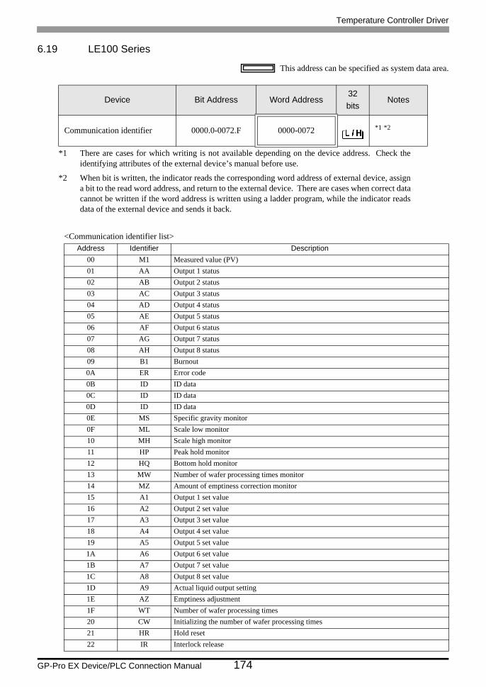
Temperature Controller Driver
GP-Pro EX Device/PLC Connection Manual 174
6.19 LE100 Series
This address can be specified as system data area.
<Communication identifier list>
Device Bit Address Word Address32bits
Notes
Communication identifier 0000.0-0072.F 0000-0072 *1 *2
*1 There are cases for which writing is not available depending on the device address. Check the identifying attributes of the external device’s manual before use.
*2 When bit is written, the indicator reads the corresponding word address of external device, assign a bit to the read word address, and return to the external device. There are cases when correct data cannot be written if the word address is written using a ladder program, while the indicator reads data of the external device and sends it back.
Address Identifier Description00 M1 Measured value (PV)01 AA Output 1 status02 AB Output 2 status03 AC Output 3 status04 AD Output 4 status05 AE Output 5 status06 AF Output 6 status07 AG Output 7 status08 AH Output 8 status09 B1 Burnout0A ER Error code0B ID ID data0C ID ID data0D ID ID data0E MS Specific gravity monitor0F ML Scale low monitor10 MH Scale high monitor11 HP Peak hold monitor12 HQ Bottom hold monitor13 MW Number of wafer processing times monitor14 MZ Amount of emptiness correction monitor15 A1 Output 1 set value16 A2 Output 2 set value17 A3 Output 3 set value18 A4 Output 4 set value19 A5 Output 5 set value1A A6 Output 6 set value1B A7 Output 7 set value1C A8 Output 8 set value1D A9 Actual liquid output setting1E AZ Emptiness adjustment1F WT Number of wafer processing times20 CW Initializing the number of wafer processing times21 HR Hold reset22 IR Interlock release
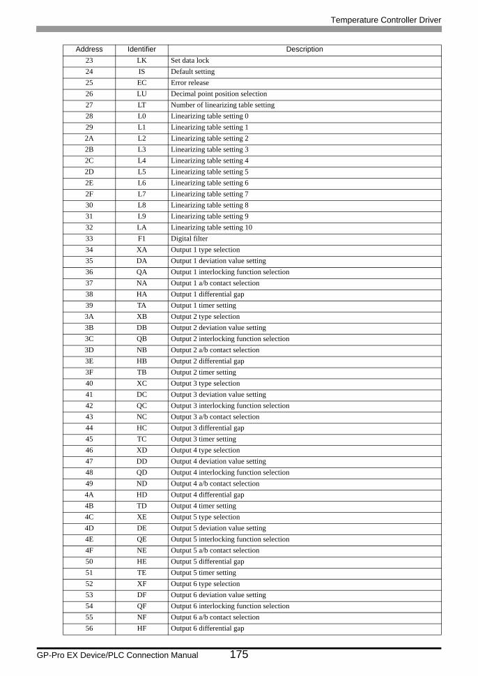
Temperature Controller Driver
GP-Pro EX Device/PLC Connection Manual 175
23 LK Set data lock24 IS Default setting25 EC Error release26 LU Decimal point position selection27 LT Number of linearizing table setting28 L0 Linearizing table setting 029 L1 Linearizing table setting 12A L2 Linearizing table setting 22B L3 Linearizing table setting 32C L4 Linearizing table setting 42D L5 Linearizing table setting 52E L6 Linearizing table setting 62F L7 Linearizing table setting 730 L8 Linearizing table setting 831 L9 Linearizing table setting 932 LA Linearizing table setting 1033 F1 Digital filter34 XA Output 1 type selection35 DA Output 1 deviation value setting36 QA Output 1 interlocking function selection37 NA Output 1 a/b contact selection38 HA Output 1 differential gap39 TA Output 1 timer setting3A XB Output 2 type selection3B DB Output 2 deviation value setting3C QB Output 2 interlocking function selection3D NB Output 2 a/b contact selection3E HB Output 2 differential gap3F TB Output 2 timer setting40 XC Output 3 type selection41 DC Output 3 deviation value setting42 QC Output 3 interlocking function selection43 NC Output 3 a/b contact selection44 HC Output 3 differential gap45 TC Output 3 timer setting46 XD Output 4 type selection47 DD Output 4 deviation value setting48 QD Output 4 interlocking function selection49 ND Output 4 a/b contact selection4A HD Output 4 differential gap4B TD Output 4 timer setting4C XE Output 5 type selection4D DE Output 5 deviation value setting4E QE Output 5 interlocking function selection4F NE Output 5 a/b contact selection50 HE Output 5 differential gap51 TE Output 5 timer setting52 XF Output 6 type selection53 DF Output 6 deviation value setting54 QF Output 6 interlocking function selection55 NF Output 6 a/b contact selection56 HF Output 6 differential gap
Address Identifier Description
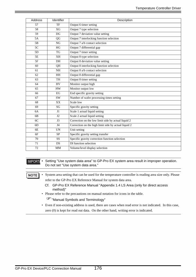
Temperature Controller Driver
GP-Pro EX Device/PLC Connection Manual 176
57 TF Output 6 timer setting58 XG Output 7 type selection59 DG Output 7 deviation value setting5A QG Output 7 interlocking function selection5B NG Output 7 a/b contact selection5C HG Output 7 differential gap5D TG Output 7 timer setting5E XH Output 8 type selection5F DH Output 8 deviation value setting60 QH Output 8 interlocking function selection61 NH Output 8 a/b contact selection62 HH Output 8 differential gap63 TH Output 8 timer setting64 HV Monitor output high65 HW Monitor output low66 EG End specific gravity setting67 SW Number of wafer processing times setting68 XX Scale low69 SG Specific gravity setting6A J1 Scale 1 actual liquid setting6B J2 Scale 2 actual liquid setting6C J3 Correction on the low limit side by actual liquid 26D J4 Correction on the high limit side by actual liquid 26E UN Unit setting6F SP Specific gravity setting transfer70 SS Specific gravity correction function selection71 DS DI function selection72 MM Volume/level display selection
• Setting "Use system data area" to GP-Pro EX system area result in improper operation. Do not set "Use system data area."
• System area setting that can be used for the temperature controller is reading area size only. Please refer to the GP-Pro EX Reference Manual for system data area.Cf. GP-Pro EX Reference Manual "Appendix 1.4 LS Area (only for direct access
method)"• Please refer to the precautions on manual notation for icons in the table.
"Manual Symbols and Terminology"• Even if non-existing address is used, there are cases when read error is not indicated. In this case,
zero (0) is kept for read out data. On the other hand, writing error is indicated.
Address Identifier Description
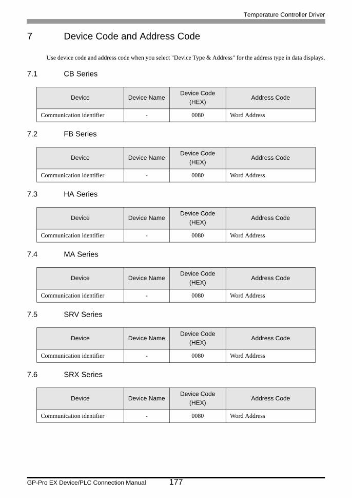
Temperature Controller Driver
GP-Pro EX Device/PLC Connection Manual 177
7 Device Code and Address Code
Use device code and address code when you select "Device Type & Address" for the address type in data displays.
7.1 CB Series
7.2 FB Series
7.3 HA Series
7.4 MA Series
7.5 SRV Series
7.6 SRX Series
Device Device NameDevice Code
(HEX)Address Code
Communication identifier - 0080 Word Address
Device Device NameDevice Code
(HEX)Address Code
Communication identifier - 0080 Word Address
Device Device NameDevice Code
(HEX)Address Code
Communication identifier - 0080 Word Address
Device Device NameDevice Code
(HEX)Address Code
Communication identifier - 0080 Word Address
Device Device NameDevice Code
(HEX)Address Code
Communication identifier - 0080 Word Address
Device Device NameDevice Code
(HEX)Address Code
Communication identifier - 0080 Word Address
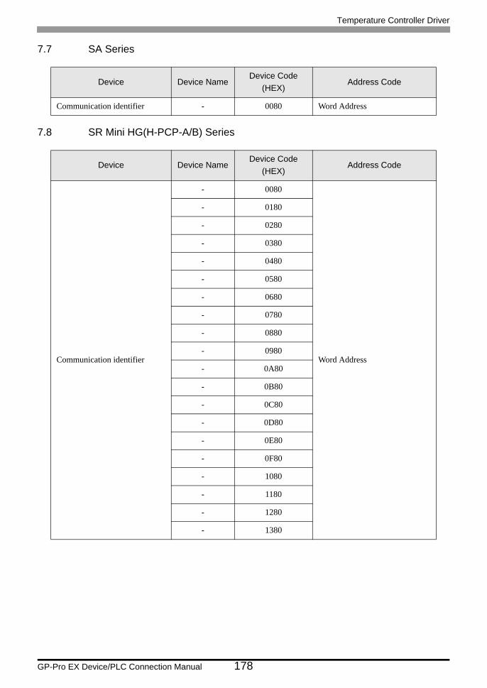
Temperature Controller Driver
GP-Pro EX Device/PLC Connection Manual 178
7.7 SA Series
7.8 SR Mini HG(H-PCP-A/B) Series
Device Device NameDevice Code
(HEX)Address Code
Communication identifier - 0080 Word Address
Device Device NameDevice Code
(HEX)Address Code
Communication identifier
- 0080
Word Address
- 0180
- 0280
- 0380
- 0480
- 0580
- 0680
- 0780
- 0880
- 0980
- 0A80
- 0B80
- 0C80
- 0D80
- 0E80
- 0F80
- 1080
- 1180
- 1280
- 1380
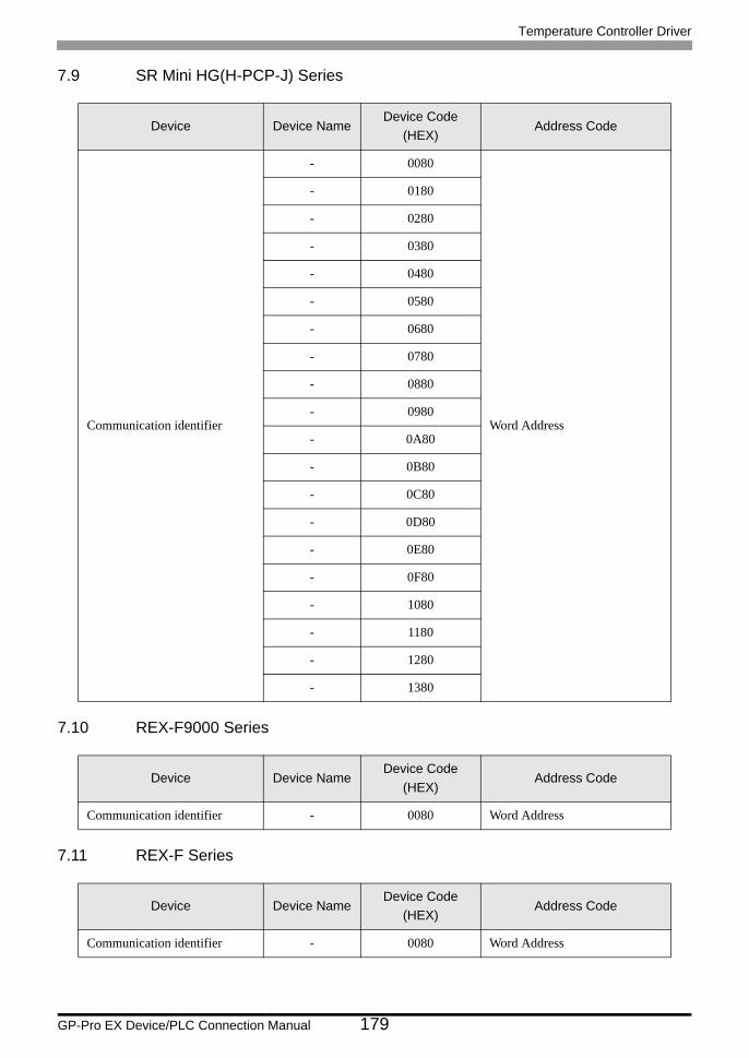
Temperature Controller Driver
GP-Pro EX Device/PLC Connection Manual 179
7.9 SR Mini HG(H-PCP-J) Series
7.10 REX-F9000 Series
7.11 REX-F Series
Device Device NameDevice Code
(HEX)Address Code
Communication identifier
- 0080
Word Address
- 0180
- 0280
- 0380
- 0480
- 0580
- 0680
- 0780
- 0880
- 0980
- 0A80
- 0B80
- 0C80
- 0D80
- 0E80
- 0F80
- 1080
- 1180
- 1280
- 1380
Device Device NameDevice Code
(HEX)Address Code
Communication identifier - 0080 Word Address
Device Device NameDevice Code
(HEX)Address Code
Communication identifier - 0080 Word Address
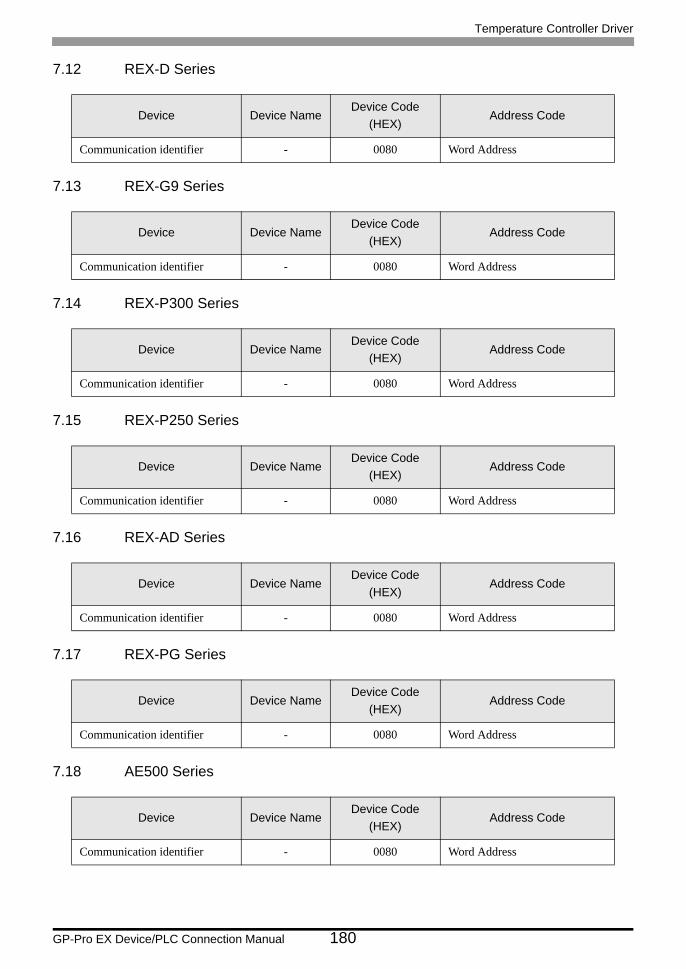
Temperature Controller Driver
GP-Pro EX Device/PLC Connection Manual 180
7.12 REX-D Series
7.13 REX-G9 Series
7.14 REX-P300 Series
7.15 REX-P250 Series
7.16 REX-AD Series
7.17 REX-PG Series
7.18 AE500 Series
Device Device NameDevice Code
(HEX)Address Code
Communication identifier - 0080 Word Address
Device Device NameDevice Code
(HEX)Address Code
Communication identifier - 0080 Word Address
Device Device NameDevice Code
(HEX)Address Code
Communication identifier - 0080 Word Address
Device Device NameDevice Code
(HEX)Address Code
Communication identifier - 0080 Word Address
Device Device NameDevice Code
(HEX)Address Code
Communication identifier - 0080 Word Address
Device Device NameDevice Code
(HEX)Address Code
Communication identifier - 0080 Word Address
Device Device NameDevice Code
(HEX)Address Code
Communication identifier - 0080 Word Address
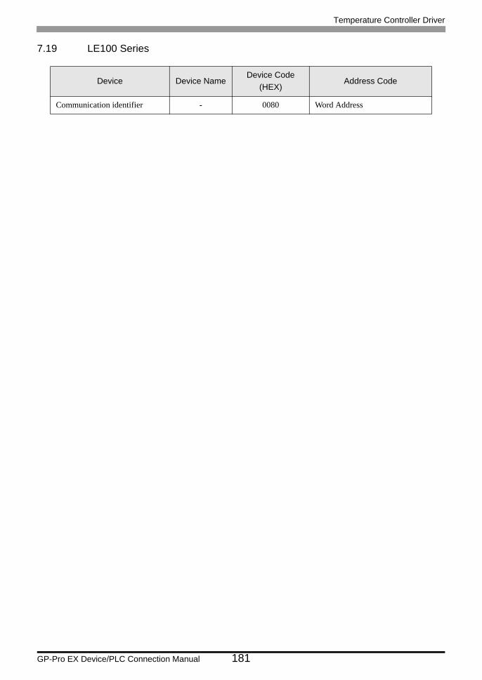
Temperature Controller Driver
GP-Pro EX Device/PLC Connection Manual 181
7.19 LE100 Series
Device Device NameDevice Code
(HEX)Address Code
Communication identifier - 0080 Word Address
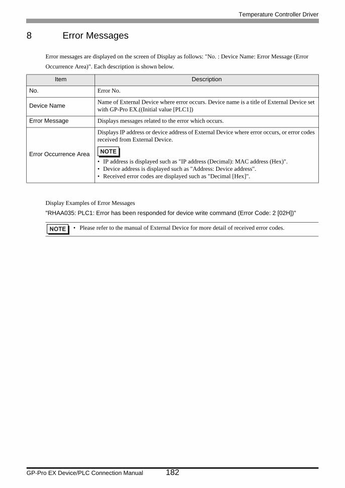
Temperature Controller Driver
GP-Pro EX Device/PLC Connection Manual 182
8 Error Messages
Error messages are displayed on the screen of Display as follows: "No. : Device Name: Error Message (Error
Occurrence Area)". Each description is shown below.
Display Examples of Error Messages
"RHAA035: PLC1: Error has been responded for device write command (Error Code: 2 [02H])"
Item Description
No. Error No.
Device Name Name of External Device where error occurs. Device name is a title of External Device set with GP-Pro EX.((Initial value [PLC1])
Error Message Displays messages related to the error which occurs.
Error Occurrence Area
Displays IP address or device address of External Device where error occurs, or error codes received from External Device.
• IP address is displayed such as "IP address (Decimal): MAC address (Hex)".• Device address is displayed such as "Address: Device address".• Received error codes are displayed such as "Decimal [Hex]".
• Please refer to the manual of External Device for more detail of received error codes.