Embed Size (px)
Citation preview
ThermoControl Temperature ControllerElectronic temperature controller with timer (clock controller) for flush mounting and for smartfunction (this function sets the time at which the comfort temperature should be reached)
Universal controller HRT 6015-50 for optionaluse as
Floor temperature controller 10 to 60 °C,
Room temperature controller 5 to 30 °C
Room temperature controller 5 to 30 °Cwith floor temperature monitoring
Room temperature controller 5 to 30 °C
Floor temperature controller 10 to 40 °C
The room temperature controllers can also be used as cooling controllers (see “Commissioning”).
Smart operation is activated on all controller types.Also available as master controller (option) for connecting clockless bi-metal and/or electrical controllers assatellites.
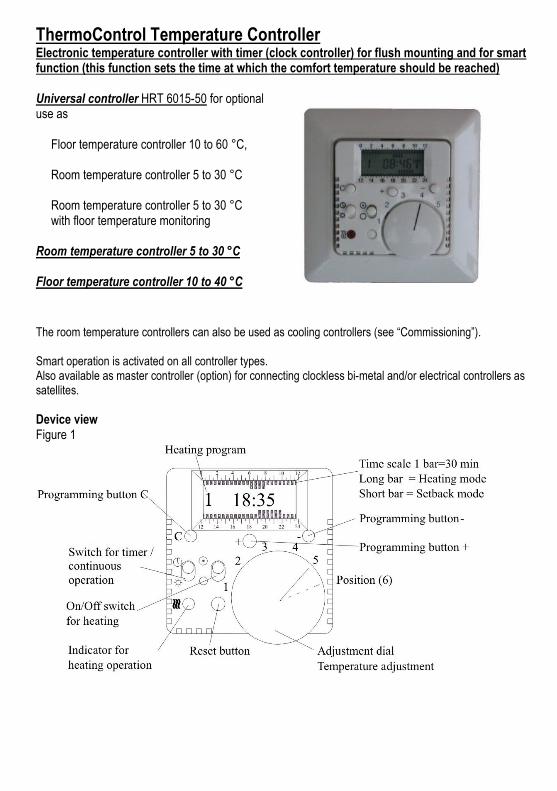
Device viewFigure 1
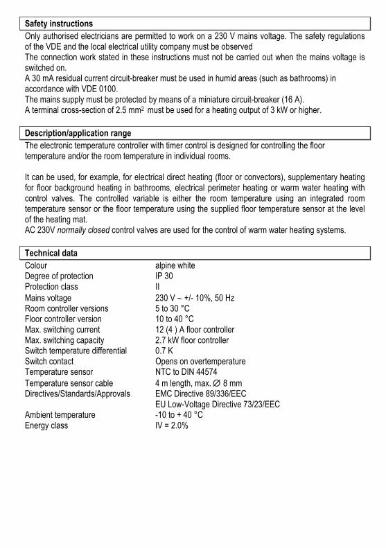
Safety instructions
Only authorised electricians are permitted to work on a 230 V mains voltage. The safety regulationsof the VDE and the local electrical utility company must be observedThe connection work stated in these instructions must not be carried out when the mains voltage isswitched on.A 30 mA residual current circuit-breaker must be used in humid areas (such as bathrooms) inaccordance with VDE 0100.The mains supply must be protected by means of a miniature circuit-breaker (16 A).A terminal cross-section of 2.5 mm2 must be used for a heating output of 3 kW or higher.
Description/application range
The electronic temperature controller with timer control is designed for controlling the floortemperature and/or the room temperature in individual rooms.
It can be used, for example, for electrical direct heating (floor or convectors), supplementary heatingfor floor background heating in bathrooms, electrical perimeter heating or warm water heating withcontrol valves. The controlled variable is either the room temperature using an integrated roomtemperature sensor or the floor temperature using the supplied floor temperature sensor at the levelof the heating mat.AC 230V normally closed control valves are used for the control of warm water heating systems.
Technical data
Colour alpine whiteDegree of protection IP 30Protection class IIMains voltage 230 V +/- 10%, 50 HzRoom controller versions 5 to 30 °CFloor controller version 10 to 40 °CMax. switching current 12 (4 ) A floor controllerMax. switching capacity 2.7 kW floor controllerSwitch temperature differential 0.7 KSwitch contact Opens on overtemperatureTemperature sensor NTC to DIN 44574Temperature sensor cable 4 m length, max. 8 mmDirectives/Standards/Approvals EMC Directive 89/336/EEC
EU Low-Voltage Directive 73/23/EECAmbient temperature -10 to + 40 °CEnergy class IV = 2.0%
Installation instructions - Mounting options
Installing the floor temperature sensorInstall the floor sensor in a separate protective tube at the heating mat level centrally between theheating cables.
ATTENTION: Apart from when only room temperature control is required, a floor temperature sensormust always be connected. Failure to do so will turn off the heater.
With room temperature control systems with floor heating, it must be ensured that the floor is notoverheated. With the universal controller it is possible to implement a temperature monitor function(floor temperature monitoring) by using the floor sensor (default setting). The floor limit temperaturethat is not to be exceeded can be set in the controller.(see “Changing controller options”)
Installing temperature controllersInstallation in standard conduit box. When using additional intermediate terminalsthe use of a deep conduit box is recommended.Mounting height: Approx. 1.5 m above floor.Avoid exposure to water.
When used as a room temperature controller, ensure that normal room air reaches the controllerwithout obstruction. The controller should not be mounted in shelf walls, under curtains or on outdoorwalls.External heat from sunlight and draughts from windows and doors impair the accuracy of thecontroller and should be avoided.
The frame can be exchanged for switch frames (if required with intermediate frame) from Busch-Jaeger, Berker or similar, in order to adapt the controller to different switch systems
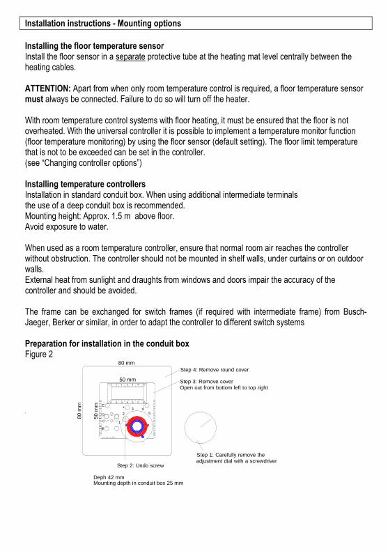
Preparation for installation in the conduit boxFigure 2
-+C
~ ~ ~
1
2 543
20 4 6 8 10 12
12 16 20 22 241814
50
mm
50 mm
80 mm
80
mm
Step 4: Remove round cover
Open out from bottom left to top rightStep 3: Remove cover
Step 1: Carefully remove theadjustment dial with a screwdriver
Step 2: Undo screw
Deph 42 mmMounting depth in conduit box 25 mm
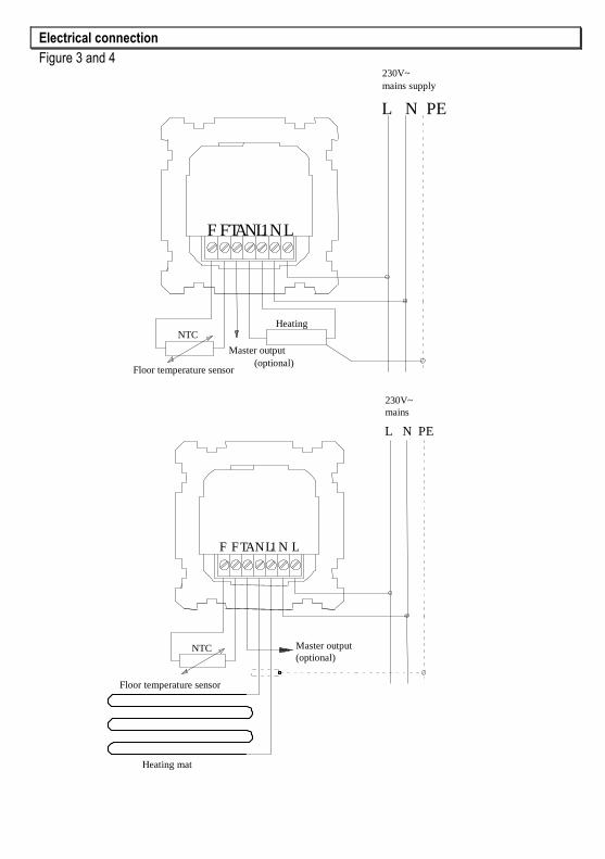
Electrical connection
Figure 3 and 4
L N PE
TAFF NL1NL
HeatingNTC
230V~
mains supply
Floor temperature sensor
Master output
(optional)
L N PE
TAFF NL1 N L
NTC
230V~mains
Floor temperature sensor
Heating mat
Master output(optional)
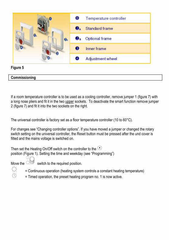
Figure 5
Commissioning
If a room temperature controller is to be used as a cooling controller, remove jumper 1 (figure 7) witha long nose pliers and fit it in the two upper sockets. To deactivate the smart function remove jumper2 (figure 7) and fit it into the two sockets on the right.
The universal controller is factory set as a floor temperature controller (10 to 60°C).
For changes see “Changing controller options”. If you have moved a jumper or changed the rotaryswitch setting on the universal controller, the Reset button must be pressed after the und cover isfitted and the mains voltage is switched on.
Then set the Heating On/Off switch on the controller to theposition (Figure 1). Setting the time and weekday (see “Programming”)
Move the switch to the required position.
= Continuous operation (heating system controls a constant heating temperature)
= Timed operation, the preset heating program no. 1 is now active.
Mon ... Fri Sat, Sun TypeNo. 1 06.00 ... 08.00 07.00 ... 09.00 Bath
19.00 ... 22.00 20.00 ... 23.00 room
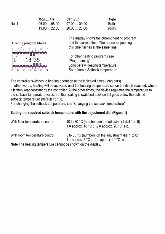
The display shows the current heating programand the current time. The bar corresponding tothis time flashes at the same time.
For other heating programs see“Programming”Long bars = Heating temperatureShort bars = Setback temperature
The controller switches to heating operation at the indicated times (long bars).In other words, heating will be activated until the heating temperature set on the dial is reached, whenit is then kept constant by the controller. At the other times, the device regulates the temperature tothe setback temperature value, i.e. the heating is switched back on if it goes below the definedsetback temperature (default 15 °C).For changing the setback temperature, see “Changing the setback temperature”
Setting the required setback temperature with the adjustment dial (Figure 1)
With floor temperature control 10 to 60 °C (numbers on the adjustment dial 1 to 6)1 = approx. 10 °C ; 2 = approx. 20 °C etc.
With room temperature control 5 to 30 °C (numbers on the adjustment dial 1 to 6)1 = approx. 5 °C ; 2 = approx. 10 °C etc.
Note The heating temperature cannot be shown on the display.
:18 35
0 2 4 8 10 12
24222018161412
6
1
Heating program Mo-Fr
Programming
Remember when programming that any changes are accepted automatically after10 seconds!A change, for example between time and date is not possible in this time.The device automatically switches to operating status.
Setting the timeNote: The Time and date are automatically set and reset if a flush mounted radio clock is connected.Manual time and date setting is not necessary.
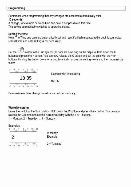
Set the switch to the Sun symbol (all bars are now long on the display). Hold down the Cbutton and press the + button. You can now release the C button and set the time with the + or –buttons. Holding the button down for a long time first changes the setting slowly and then increasinglyfaster.
:18 35
0 2 4 6 8 10 12
242220181612 14
Example with time setting
18 : 35
Summer/winter time changes must be carried out manually.
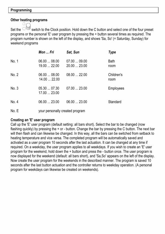
Weekday settingLeave the switch at the Sun position. Hold down the C button and press the – button. You can nowrelease the C button and set the current weekday with the + or – buttons.1 = Monday, 2 = Tuesday, ... 7 = Sunday.
Examples:
2
0 2 4 6 8 10 12
12 14 16 18 20 2422
WeekdayExample
2 = Tuesday
Programming
Other heating programs
Set the switch to the Clock position. Hold down the C button and select one of the four presetprograms or the personal 'E' user program by pressing the + button several times as required. Theprogram number is shown on the left of the display, and shows 'Sa, So' (= Saturday, Sunday) forweekend programs
Mon ... Fri Sat, Sun Type
No. 1 06.00 ... 08.00 07.00 ... 09.00 Bath19.00 ... 22.00 20.00 ... 23.00 room
No. 2 06.00 ... 08.00 08.00 ... 22.00 Children's14.00 ... 22.00 room
No. 3 05.30 ... 07.30 07.00 ... 23.00 Employees17.00 ... 23.00
No. 4 06.00 ... 23.00 06.00 ... 23.00 Standard
No. E your personally created program
Creating an 'E' user programCall up the 'E' user program (default setting: all bars short). Select the bar to be changed (nowflashing quickly) by pressing the + or - button. Change the bar by pressing the C button. The next barwill then flash and can likewise be changed. In this way, all the bars can be switched from setback toheating temperature and vice versa. The completed program will be automatically saved andactivated as a user program 10 seconds after the last actuation. It can be changed at any time ifrequired. On a weekday, the user program applies to all weekdays. If you wish to create an 'E' userprogram for the weekend, hold down the + button and press the - button once. The user program isnow displayed for the weekend (default: all bars short), and 'Sa,So' appears on the left of the display.Now create the user program for the weekends in the described manner. The program is saved 10seconds after the last button actuation and the controller returns to weekday operation. (A personalprogram for weekdays can likewise be created on weekends).
Programming
Changing the setback temperature(default setting 15 °C)
Set the switch to the Sun symbol (all bars are now long on the display).Set the new setback temperature required with the adjustment dial (see Figure 1).Hold down the + button and press the – button once.The new setback temperature is now saved and is shown briefly on the display for control purposes.It is retained when the program is changed.Turn the adjustment dial back to the required heating temperature and if necessary move up the slideswitch to the clock position.
Min. set-back temperature on floor temperature controller: 10 °CMin. set-back temperature on room temperature controller: 5 °C
Changing the controller options of the universal controller
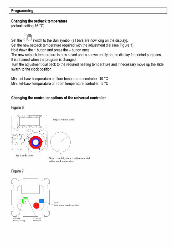
Figure 6
Figure 7
-+C
~~~1
2 543
20 4 6 8 10 12
12 16 20 22 241814
Step 3: remove cover
Step 1: carefully remove adjustment dial
with a small screwdriver
Set 2: undo screw
Step 4:
Set the required controller option here
J1 (Jumper)
Heating / cooling
J2 (Jumper)
Smart mode
Changing the controller options of the universal controller with rotary switch
Position 0 Floor temperature controller 10 to 60 °CIn this position the room temperature controller is switched off
Position 1 Room temperature controller 5 to 30 °CIn this position the floor temperature controller is switched off
Room temperature controller 5 to 30 °C with optionalfloor limit temperature
Position 2 28 °C for sensitive parquet flooring or laminatePosition 3 31 °C optional intermediate valuePosition 4 34 °C optional intermediate valuePosition 5 44 °C to DIN 44 576 for electrical floor direct heating
(default setting)Position 6 55°C to DIN 44 576 for electrical perimeter heatingPosition 7 Reserve
Attention!The Reset button must be pressed after a controller option is changed.The change is activated automatically after approx. 60 to 90 secs. If necessary reset the personal 'E'user program and the set-back temperature.
Reset buttonPressing the Reset button sets the controller back to the default setting.
The user program E is deleted Set-back temperature = 15 °C Date/ time is unchanged The set controller option is unchanged
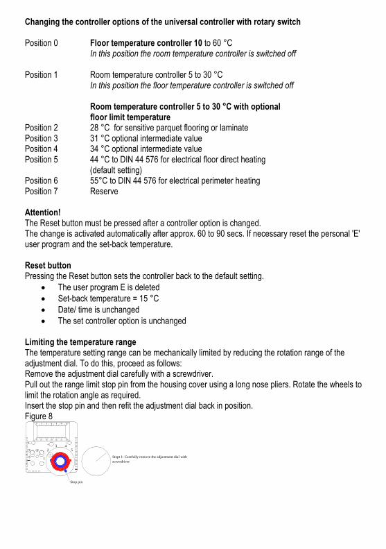
Limiting the temperature rangeThe temperature setting range can be mechanically limited by reducing the rotation range of theadjustment dial. To do this, proceed as follows:Remove the adjustment dial carefully with a screwdriver.Pull out the range limit stop pin from the housing cover using a long nose pliers. Rotate the wheels tolimit the rotation angle as required.Insert the stop pin and then refit the adjustment dial back in position.Figure 8
-+C
~~~1
2 543
20 4 6 8 10 12
12 16 20 22 241814
Stept 1: Carefully remove the adjustment dial with
screwdriver
Stop pin
Mains supply failureThe heater switches off in the event of a mains supply failure and the upper bar of thedisplay flashes. The device resumes its previous operation if the mains voltage is restored withinapprox. 1 to 1 ½ days. If the mains supply failure is longer, the time and weekday must be reset andthe 'E' user program may have to be re-entered. The set-back temperature must also bereprogrammed if this was altered.
Short-circuit or interruption in the sensor line: The heating system is disconnected and the LEDflashes. CAUTION: In the event of a fault, the mains voltage may still be present on the sensor line
Special master controllers for connecting satellitesAll controllers listed can be supplied as master controllers for connecting satellites. The TA output canbe used to connect virtually any number of clockless temperature controllers, e.g. commerciallyavailable bimetal controllers with their L set-back input TA as satellites. If the master controller with itstimer switches to set-back operation, all satellites do the same.
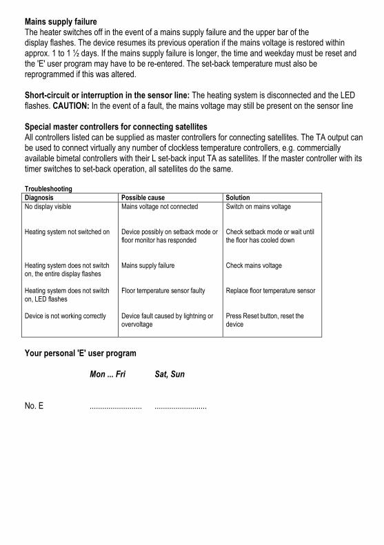
TroubleshootingDiagnosis Possible cause SolutionNo display visible
Heating system not switched on
Heating system does not switchon, the entire display flashes
Heating system does not switchon, LED flashes
Device is not working correctly
Mains voltage not connected
Device possibly on setback mode orfloor monitor has responded
Mains supply failure
Floor temperature sensor faulty
Device fault caused by lightning orovervoltage
Switch on mains voltage
Check setback mode or wait untilthe floor has cooled down
Check mains voltage
Replace floor temperature sensor
Press Reset button, reset thedevice
Your personal 'E' user program
Mon ... Fri Sat, Sun
No. E ......................... .........................

Reservation of rightSubject to technical modifications.Compensation cannot be claimed on account of modifications, errors or print errors.