Embed Size (px)
Citation preview

MODEL 53401 TEMPORARY EXTERNAL PACEMAKER
Model 53401 Single Chamber Temporary Pacemaker
TIP CARD
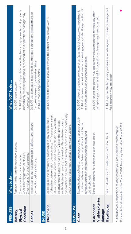
PRE-
US
EW
hat t
o do
...
Wha
t NO
T to
do
...
Bat
tery
Rep
lace
the
batt
ery
for e
ach
new
pat
ient
.D
o N
OT
reus
e ba
tter
y.
Phys
ical
C
ondi
tion
C
heck
cas
e fo
r cra
cks/
dam
age.
Che
ck b
atte
ry d
raw
er fo
r clo
sure
.C
heck
dis
play
for c
rack
s/da
mag
e.
Do
NO
T ig
nore
vis
ible
phy
sica
l dam
age;
the
devi
ce m
ay a
ppea
r to
wo
rk p
rope
rly
imm
edia
tely
aft
er b
eing
dro
pped
or m
isha
ndle
d, b
ut o
pera
tiona
l dam
age
may
ha
ve o
ccur
red.
Cab
les
Insp
ect c
able
s an
d le
ads
for p
oss
ible
def
ects
, and
sec
ure
conn
ectio
n be
fore
eac
h us
e.D
o N
OT
use
dam
aged
lead
s o
r cab
les.
Impr
ope
r co
nnec
tion,
dis
plac
emen
t, o
r fr
actu
re m
ay re
sult
in p
acem
aker
failu
re.
Do
NO
T re
use
sing
le-u
se c
able
s.
IN U
SE
Plac
emen
tD
o n
ot p
lace
the
tem
pora
ry p
acem
aker
in a
ny a
rea
out
side
o
f the
dire
ct o
bser
vati
on
by m
edic
al s
taff
. If n
eces
sary
, ins
ert
into
a D
ispo
sabl
e P
ouc
h† (see
-thr
oug
h p
last
ic p
ock
et) w
ith
an a
ttac
hmen
t pan
el (t
o h
ang
fro
m IV
po
le) t
hat p
rote
cts
and
hold
s th
e te
mpo
rary
pac
emak
er. P
lace
the
tem
pora
ry
pace
mak
er in
an
area
tha
t min
imiz
es a
cces
s to
the
co
ntro
ls b
y un
auth
oriz
ed p
erso
nnel
, suc
h as
pat
ient
s an
d vi
sito
rs.
Do
NO
T p
lace
the
devi
ce in
any
are
a w
here
the
patie
nt m
ay in
tera
ct w
ith it
.
POST
-US
EC
lean
Exte
rnal
sur
face
s of
uni
t can
be
clea
ned
usin
g a
spon
ge o
r clo
th
moi
sten
ed w
ith w
ater
or 7
0% is
opro
pyl a
lcoh
ol. F
or in
tern
al
surf
aces
, sen
d to
Med
tron
ic fo
r cle
anin
g, s
afet
y, a
nd
tech
nica
l che
ck.
Do
NO
T a
ttem
pt to
cle
an a
ny in
tern
al s
urfa
ces,
incl
udin
g ba
tter
y co
mpa
rtm
ent.
Do
NO
T im
mer
se th
e de
vice
in w
ater
or c
lean
ing
agen
ts; d
o N
OT
exp
ose
the
unit
to e
ther
s, a
ceto
ne, o
r chl
orin
ated
so
lven
ts.
If d
ropp
ed/
Vis
ible
ext
erio
r da
mag
e
Send
to M
edtr
oni
c fo
r saf
ety
and
tech
nica
l che
ck.
Do
NO
T ig
nore
; the
dev
ice
may
app
ear t
o w
ork
app
ropr
iate
ly im
med
iate
ly a
fter
be
ing
dro
pped
or m
isha
ndle
d, b
ut o
pera
tiona
l dam
age
may
hav
e o
ccur
red.
If s
pille
d on
Send
to M
edtr
oni
c fo
r saf
ety
and
tech
nica
l che
ck.
Do
NO
T ig
nore
; the
tem
pora
ry p
acem
aker
was
des
igne
d to
min
imiz
e le
akag
e, b
ut
fluid
incu
rsio
n m
ay s
till o
ccur
.
* S
houl
d se
rvic
e or
repa
ir be
nec
essa
ry, c
onta
ct y
our l
ocal
Med
tron
ic re
pres
enta
tive.
† Dis
posa
ble
Pouc
h av
aila
ble
for t
he M
odel
534
01 T
empo
rary
Pac
emak
er; M
odel
#54
09.
2
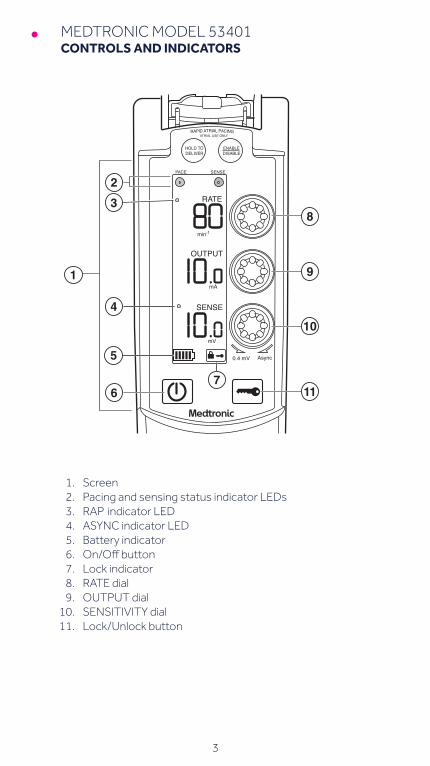
MEDTRONIC MODEL 53401CONTROLS AND INDICATORS
3
min-1
mA
mV
0.4 mV
HOLD TO DELIVER
PACE SENSE
ENABLEDISABLE
ATRIAL USE ONLYRAPID ATRIAL PACING
RATE
OUTPUT
SENSE
Async
1. Screen 2. Pacing and sensing status indicator LEDs 3. RAP indicator LED 4. ASYNC indicator LED 5. Battery indicator 6. On/Offbutton 7. Lock indicator 8. RATE dial 9. OUTPUT dial 10. SENSITIVITY dial 11. Lock/Unlock button
4
MEDTRONIC MODEL 53401BASIC OPERATION
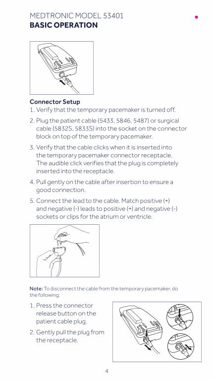
Connector Setup1. Verify that the temporary pacemaker is turned off.
2. Plug the patient cable (5433, 5846, 5487) or surgical cable (5832S, 5833S) into the socket on the connector block on top of the temporary pacemaker.
3. Verify that the cable clicks when it is inserted into the temporary pacemaker connector receptacle. The audible click verifies that the plug is completely inserted into the receptacle.
4. Pull gently on the cable after insertion to ensure a good connection.
5. Connect the lead to the cable. Match positive (+) and negative (-) leads to positive (+) and negative (-) sockets or clips for the atrium or ventricle.
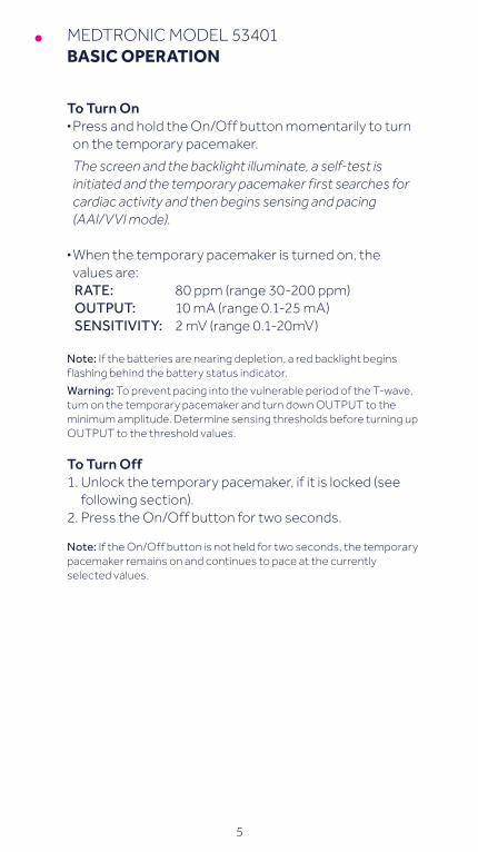
Note: To disconnect the cable from the temporary pacemaker, do the following:
1. Press the connector release button on the patient cable plug.
2. Gently pull the plug from the receptacle.
5
MEDTRONIC MODEL 53401BASIC OPERATION
To Turn On§ Press and hold the On/Off button momentarily to turn
on the temporary pacemaker.
The screen and the backlight illuminate, a self-test is initiated and the temporary pacemaker first searches for cardiac activity and then begins sensing and pacing (AAI/VVI mode).
§ When the temporary pacemaker is turned on, the values are:RATE: 80 ppm (range 30-200 ppm)OUTPUT: 10 mA (range 0.1-25 mA)SENSITIVITY: 2 mV (range 0.1-20mV)
Note: If the batteries are nearing depletion, a red backlight begins flashing behind the battery status indicator.
Warning: To prevent pacing into the vulnerable period of the T-wave, turn on the temporary pacemaker and turn down OUTPUT to the minimum amplitude. Determine sensing thresholds before turning up OUTPUT to the threshold values.
To Turn Off1. Unlock the temporary pacemaker, if it is locked (see
following section).2. Press the On/Off button for two seconds.
Note: If the On/Off button is not held for two seconds, the temporary pacemaker remains on and continues to pace at the currently selected values.
6
MEDTRONIC MODEL 53401BASIC OPERATION
Lock/UnlockThe Lock/Unlock button locks the temporary pacemaker to prevent inadvertent adjustment of the parameters, or unlocks the temporary pacemaker when it is locked.
When Locked:§ The RATE, OUTPUT, and SENSITIVITY parameter
values lock and cannot be adjusted.§ Pacing therapy continues to be delivered at the
currently selected values.§ The Lock indicator appears in the lower right corner of
the screen.§ The On/Off button and RAP buttons lock and will not
function.Notes: The temporary pacemaker locks when one of the following events occurs:§ 60 seconds elapses after the last parameter adjustment is made.§ When RAP is enabled, the temporary pacemaker will lock after
300 seconds/5 minutes have elapsed.§ The Lock/Unlock button is pressed.If any parameter dials are adjusted or any buttons are pressed while the temporary pacemaker is locked, the Lock indicator flashes.
7
MEDTRONIC MODEL 53401BASIC OPERATION
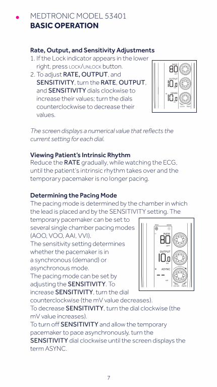
Rate, Output, and Sensitivity Adjustments1. If the Lock indicator appears in the lower
right, press lock/unlock button.2. To adjust RATE, OUTPUT, and
SENSITIVITY, turn the RATE, OUTPUT, and SENSITIVITY dials clockwise to increase their values; turn the dials counterclockwise to decrease their values.
The screen displays a numerical value that reflects the current setting for each dial.
Viewing Patient’s Intrinsic RhythmReduce the RATE gradually, while watching the ECG, until the patient’s intrinsic rhythm takes over and the temporary pacemaker is no longer pacing.
Determining the Pacing ModeThe pacing mode is determined by the chamber in which the lead is placed and by the SENSITIVITY setting. The temporary pacemaker can be set to several single chamber pacing modes (AOO, VOO, AAI, VVI).The sensitivity setting determines whether the pacemaker is in a synchronous (demand) or asynchronous mode. The pacing mode can be set by adjusting the SENSITIVITY. To increase SENSITIVITY, turn the dial counterclockwise (the mV value decreases). To decrease SENSITIVITY, turn the dial clockwise (the mV value increases). To turn off SENSITIVITY and allow the temporary pacemaker to pace asynchronously, turn the SENSITIVITY dial clockwise until the screen displays the term ASYNC.
ppm
mA
mV
PACE SENSE
RATE
OUTPUT
ASYNC
0.4 mV Async
ppm
mA
mV
RATE
OUTPUT
SENSE
0.4 mV Async
8
MEDTRONIC MODEL 53401SENSING THRESHOLDS
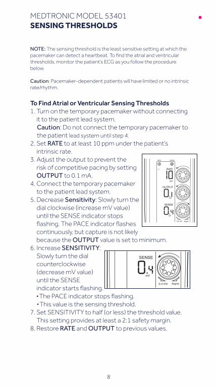
NOTE: The sensing threshold is the least sensitive setting at which the pacemaker can detect a heartbeat. To find the atrial and ventricular thresholds, monitor the patient’s ECG as you follow the procedure below.
Caution: Pacemaker-dependent patients will have limited or no intrinsic rate/rhythm.
To Find Atrial or Ventricular Sensing Thresholds1. Turn on the temporary pacemaker without connecting
it to the patient lead system.Caution: Do not connect the temporary pacemaker to the patient lead system until step 4.
2. Set RATE to at least 10 ppm under the patient’s intrinsic rate.
3. Adjust the output to prevent the risk of competitive pacing by setting OUTPUT to 0.1 mA.
4. Connect the temporary pacemaker to the patient lead system.
5. Decrease Sensitivity: Slowly turn the dial clockwise (increase mV value) until the SENSE indicator stops flashing. The PACE indicator flashes continuously, but capture is not likely because the OUTPUT value is set to minimum.
6. Increase SENSITIVITY: Slowly turn the dial counterclockwise (decrease mV value) until the SENSE indicator starts flashing. § The PACE indicator stops flashing.§ This value is the sensing threshold.
7. Set SENSITIVITY to half (or less) the threshold value. This setting provides at least a 2:1 safety margin.
8. Restore RATE and OUTPUT to previous values.
ppm
mA
mV
0.4 mV
RATE
OUTPUT
SENSE
PACE SENSE
Async
mV
SENSE
0.4 mV Async
9
MEDTRONIC MODEL 53401STIMULATION THRESHOLDS
NOTE: The stimulation threshold is the minimum output pulse needed to consistently capture the heart. To find this threshold, monitor the ECG as you follow the procedure below. To reduce the risk of competitive pacing, find the sensing threshold first (if the patient’s intrinsic rate is adequate).
To Find Atrial or Ventricular Stimulation Thresholds1. Verify that the patient is connected to the temporary
pacemaker and is being monitored on the ECG.2. Set RATE at least 10 ppm above the patient’s intrinsic
rate.
This adjustment ensures pacing. The PACE indicator will be flashing.
3. Decrease OUTPUT: Slowly turn the OUTPUT dial counterclockwise until the ECG shows loss of capture. § The PACE and SENSE indicators flash intermittently.
4. Increase OUTPUT: Slowly turn the OUTPUT dial clockwise until ECG shows consistent capture. § The PACE indicator flashes continuously; the SENSE
indicator stops flashing.§ This value is the stimulation threshold.
5. Set OUTPUT to a value at least 2 to 3 times greater than the stimulation threshold value. This setting provides at least 2:1 safety margin.
6. Restore RATE to previous value.
10
MEDTRONIC MODEL 53401RAPID ATRIAL PACING (RAP)
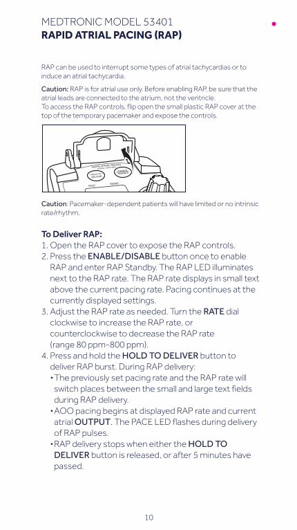
RAP can be used to interrupt some types of atrial tachycardias or to induce an atrial tachycardia.
Caution: RAP is for atrial use only. Before enabling RAP, be sure that the atrial leads are connected to the atrium, not the ventricle.To access the RAP controls, flip open the small plastic RAP cover at the top of the temporary pacemaker and expose the controls.
Caution: Pacemaker-dependent patients will have limited or no intrinsic rate/rhythm.
To Deliver RAP:1. Open the RAP cover to expose the RAP controls.2. Press the ENABLE/DISABLE button once to enable
RAP and enter RAP Standby. The RAP LED illuminates next to the RAP rate. The RAP rate displays in small text above the current pacing rate. Pacing continues at the currently displayed settings.
3. Adjust the RAP rate as needed. Turn the RATE dial clockwise to increase the RAP rate, or counterclockwise to decrease the RAP rate (range 80 ppm-800 ppm).
4. Press and hold the HOLD TO DELIVER button to deliver RAP burst. During RAP delivery:§ The previously set pacing rate and the RAP rate will
switch places between the small and large text fields during RAP delivery.§ AOO pacing begins at displayed RAP rate and current
atrial OUTPUT. The PACE LED flashes during delivery of RAP pulses.§ RAP delivery stops when either the HOLD TO
DELIVER button is released, or after 5 minutes have passed.
MEDTRONIC MODEL 53401RAPID ATRIAL PACING (RAP)
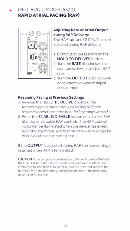
Adjusting Rate or Atrial Output during RAP Delivery:The RAP rate and OUTPUT can be adjusted during RAP delivery.
1. Continue to press and hold the HOLD TO DELIVER button.
2. Turn the RATE dial clockwise or counterclockwise to adjust RAP rate.
3. Turn the OUTPUT dial clockwise or counterclockwise to adjust atrial output.
Resuming Pacing at Previous Settings1. Release the HOLD TO DELIVER button. The
temporary pacemaker stops delivering RAP and resumes operation at the non-RAP settings within 3 s.
2. Press the ENABLE/DISABLE button once to exit RAP Standby and disable RAP controls. The RAP LED will no longer be illuminated when the device has exited RAP Standby mode, and the RAP rate will no longer be displayed above the pacing rate.
If the OUTPUT is adjusted during RAP, the new setting is retained when RAP is terminated.
CAUTION: If the temporary pacemaker continues to deliver RAP after the HOLD TO DELIVER button is released, press and hold the On/Off button to stop RAP. If RAP continues to be delivered, remove the batteries from the temporary pacemaker and return the temporary pacemaker for service.
ppm
mA
mV
0.4 mV
HOLD TO DELIVER
PACE SENSE
ENABLEDISABLE
080
OUTPUT
ASYNC
Async
BASE RATE
11
12
MEDTRONIC MODEL 53401BATTERY REPLACEMENT
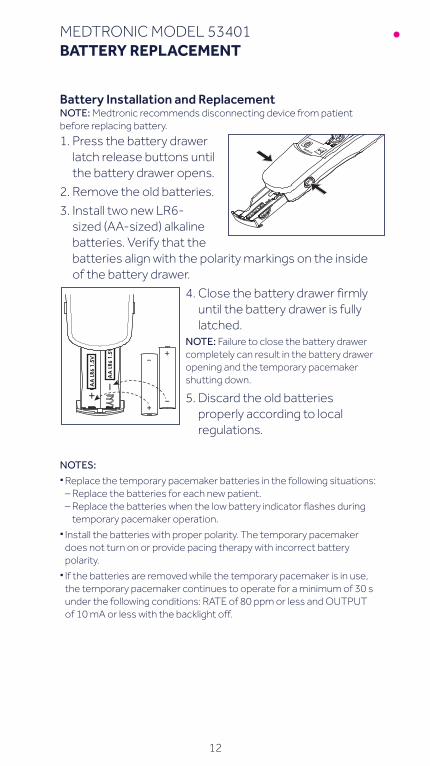
Battery Installation and ReplacementNOTE: Medtronic recommends disconnecting device from patient before replacing battery.
1. Press the battery drawer latch release buttons until the battery drawer opens.
2. Remove the old batteries.
3. Install two new LR6-sized (AA-sized) alkaline batteries. Verify that the batteries align with the polarity markings on the inside of the battery drawer.
4. Close the battery drawer firmly until the battery drawer is fully latched.
NOTE: Failure to close the battery drawer completely can result in the battery drawer opening and the temporary pacemaker shutting down.
5. Discard the old batteries properly according to local regulations.
NOTES:§ Replace the temporary pacemaker batteries in the following situations:
– Replace the batteries for each new patient. – Replace the batteries when the low battery indicator flashes during
temporary pacemaker operation.§ Install the batteries with proper polarity. The temporary pacemaker
does not turn on or provide pacing therapy with incorrect battery polarity.§ If the batteries are removed while the temporary pacemaker is in use,
the temporary pacemaker continues to operate for a minimum of 30 s under the following conditions: RATE of 80 ppm or less and OUTPUT of 10 mA or less with the backlight off.


Brief Statement For a listing of indications, contraindications, precautions, warnings, and potential adverse events, please refer to the Instructions for Use.
medtronic.ca99 Hereford StreetBrampton, Ontario L6Y 0R3 Canada
Tel: (905) 460-3800Fax: (905) 460-3998
Medtronic and the Medtronic logo are trademarks of Medtronic. *Third party brands are trademarks of their respective owners. All other brands are trademarks of a Medtronic company.UC201703608 EC © 2017 Medtronic. All Rights Reserved.
This information is intended only for users in markets where Medtronic products and therapies are approved or available for use as indicated within the respective product manuals. Content on specific Medtronic products and therapies is not intended for users in markets that do not have authorization for use.