Embed Size (px)
Citation preview
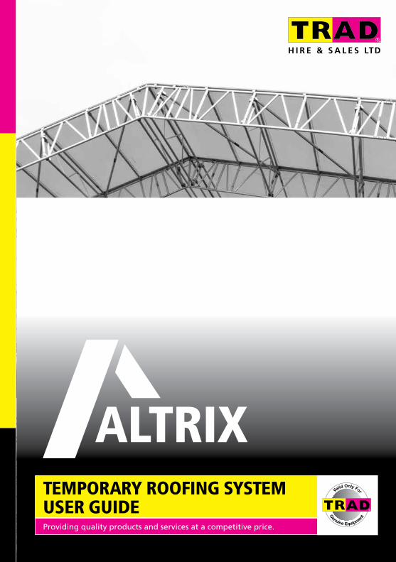
TEMPORARY ROOFING SYSTEM USER GUIDEProviding quality products and services at a competitive price.
Valid Only For
Genuine Equipment
ALTRIXTM User Guide2
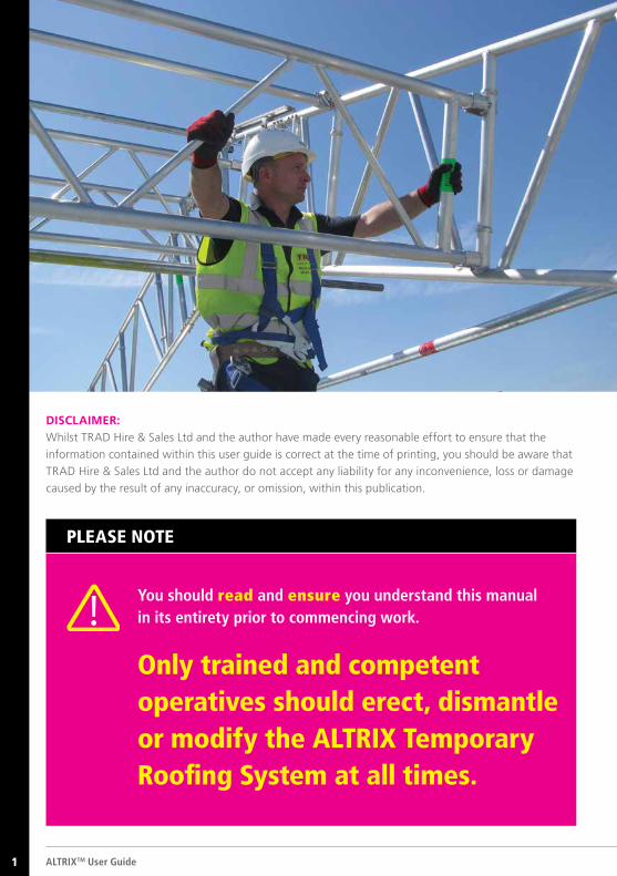
You should read and ensure you understand this manual in its entirety prior to commencing work.
Only trained and competent operatives should erect, dismantle or modify the ALTRIX Temporary Roofing System at all times.
PLEASE NOTE
DISCLAIMER: Whilst TRAD Hire & Sales Ltd and the author have made every reasonable effort to ensure that the
information contained within this user guide is correct at the time of printing, you should be aware that
TRAD Hire & Sales Ltd and the author do not accept any liability for any inconvenience, loss or damage
caused by the result of any inaccuracy, or omission, within this publication.
1
© TRAD Hire & Sales Ltd 2016 1
About TRAD Hire & Sales Ltd
About ALTRIX
ALTRIX and Safety
Manual Handling
Safety on Site
General Rules for Safety
Main Components
Ancillary Components
Bay Size Colour Coding
Erection and Dismantling Guidance
Bracing
Crane Lifting Points
Techniques
Other Products
3
5
7
9
10
11
13
20
25
26
51
53
55
57
TABLE O
F CON
TENTS
GUIDANCE NOTE
This manual is valid only for the use of Genuine ALTRIX Temporary Roofing System, supplied by TRAD Hire and Sales Limited.TRAD Hire & Sales Ltd reserve the right to alter or amend without notice the design and / or specifications of any of the equipment forming part of the ALTRIX system, in the interests of improvement.
TABLE OF CONTENTS
2
ALTRIXTM User Guide2
ABO
UT TR
AD
HIRE &
SALES LTD
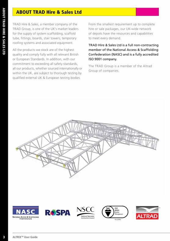
TRAD Hire & Sales, a member company of the
TRAD Group, is one of the UK’s market leaders
for the supply of system scaffolding, scaffold
tube, fittings, boards, stair towers, temporary
roofing systems and associated equipment.
All the products we stock are of the highest
quality and comply fully with all relevant British
or European Standards. In addition, with our
commitment to exceeding all safety standards,
all our products, whether sourced internationally or
within the UK, are subject to thorough testing by
qualified external UK & European testing bodies.
From the smallest requirement up to complete
hire or sale packages, our UK-wide network
of depots have the resources and capabilities
to meet every demand.
TRAD Hire & Sales Ltd is a full non-contracting member of the National Access & Scaffolding Confederation (NASC) and is a fully accredited ISO 9001 company.
The TRAD Group is a member of the Altrad
Group of companies.
ABOUT TRAD Hire & Sales Ltd
FS 614991 FS 614991
3
ABO
UT TR
AD
LOK
© TRAD Hire & Sales Ltd 2016 3
GUIDANCE NOTE
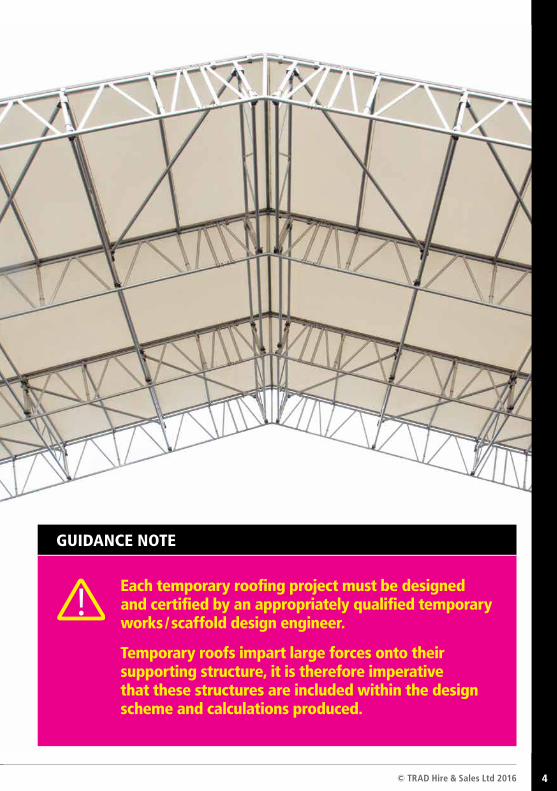
Each temporary roofing project must be designed and certified by an appropriately qualified temporary works / scaffold design engineer.
Temporary roofs impart large forces onto their supporting structure, it is therefore imperative that these structures are included within the design scheme and calculations produced.
4
4 ALTRIXTM User Guide
ABO
UT A
LTRIX
ABOUT ALTRIX
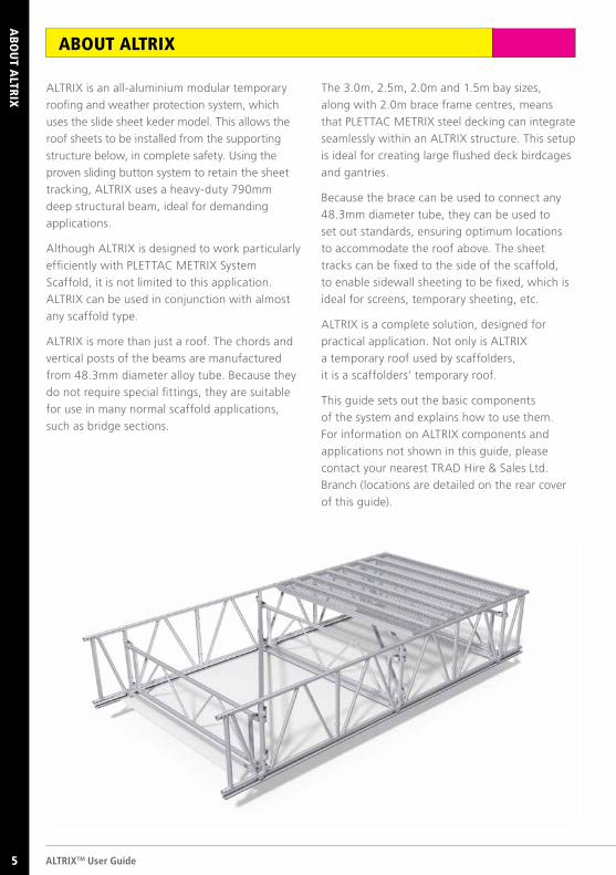
ALTRIX is an all-aluminium modular temporary
roofing and weather protection system, which
uses the slide sheet keder model. This allows the
roof sheets to be installed from the supporting
structure below, in complete safety. Using the
proven sliding button system to retain the sheet
tracking, ALTRIX uses a heavy-duty 790mm
deep structural beam, ideal for demanding
applications.
Although ALTRIX is designed to work particularly
efficiently with PLETTAC METRIX System
Scaffold, it is not limited to this application.
ALTRIX can be used in conjunction with almost
any scaffold type.
ALTRIX is more than just a roof. The chords and
vertical posts of the beams are manufactured
from 48.3mm diameter alloy tube. Because they
do not require special fittings, they are suitable
for use in many normal scaffold applications,
such as bridge sections.
The 3.0m, 2.5m, 2.0m and 1.5m bay sizes,
along with 2.0m brace frame centres, means
that PLETTAC METRIX steel decking can integrate
seamlessly within an ALTRIX structure. This setup
is ideal for creating large flushed deck birdcages
and gantries.
Because the brace can be used to connect any
48.3mm diameter tube, they can be used to
set out standards, ensuring optimum locations
to accommodate the roof above. The sheet
tracks can be fixed to the side of the scaffold,
to enable sidewall sheeting to be fixed, which is
ideal for screens, temporary sheeting, etc.
ALTRIX is a complete solution, designed for
practical application. Not only is ALTRIX
a temporary roof used by scaffolders,
it is a scaffolders’ temporary roof.
This guide sets out the basic components
of the system and explains how to use them.
For information on ALTRIX components and
applications not shown in this guide, please
contact your nearest TRAD Hire & Sales Ltd.
Branch (locations are detailed on the rear cover
of this guide).
5
© TRAD Hire & Sales Ltd 2016 5
ABO
UT A
LTRIX
ALTRIX offers many advantages over other forms of temporary roof, including:
Weight ALTRIX’s all aluminium construction makes the system incredibly light
and easy to handle.
Speed ALTRIX’s ease of use, along with its light weight makes the system
exceptionally quick to erect.
Compatibility ALTRIX can be supported by almost any scaffolding type.
Cost Savings ALTRIX’s versatility allows the bracing patterns to be application specific,
making the system exceptionally cost effective.
ALTRIX has ISO 9001 and EN 1090 certified manufacturing processes.
When planning, designing and constructing an ALTRIX structure reference
should be made to the current editions of the following:
Regulatory
Working at Height Regulations
Construction (Design and Management) Regulations
Management of Health and Safety Regulations
Normative
BS EN 12810-1 Façade scaffolds made of prefabricated components: Product specifications
BS EN 12811-1 scaffolds - Performance requirements & general design
BS EN 13374 Temporary edge protection systems—Product specification, test methods
BS EN 1991-1-3 Actions on structures. General actions, snow loads
BS EN 1991-1-4 Actions on structures. General actions, wind loads
BS EN 74-1 Couplers for tubes. Requirements and test procedures
Technical Guidance
NASC TG4 Anchorage systems
NASC TG9 Guide to the design and construction of temporary roofs and buildings
NASC TG14 Supplementary couplers and check couplers
NASC TG20 Guide to good practice for tube and fitting scaffold
iStructE Temporary demountable structures
Safety Guidance
NASC SG4 Preventing falls in scaffolding operations
NASC SG6 Manual handling in the scaffolding industry
NASC SG9 Use, inspection & maintenance of lifting equipment
NASC SG19 A guide to formulating a rescue plan
NASC SG35 Handover of scaffold structures
6
6
ALTRIX
AN
D SA
FETY
ALTRIX AND SAFETY
Competence of Erectors1 Work at Height / FallPrevention / Fall Mitigation2
Competence of individuals working at height
is now a direct requirement of the current
“Work at Height” regulations. Consequently,
employers have a duty to ensure that all
individuals involved in the erection, modification
or dismantling of any scaffolding equipment
have received the training necessary to enable
them to carry out their work in a safe manner.
Temporary roof structures can be amongst
the most difficult and demanding scaffolding
projects and while ALTRIX provides a safer,
more effective alternative to other systems and
traditional equipment, TRAD Hire & Sales Ltd
recommends that a minimum of four trained
and competent operatives be allowed to erect
the system.
The current edition of the Work at Height
Regulations places a duty on employers to
protect individuals from harm. Scaffolding
inevitably carries a risk of falling from height
and consequently, it is of paramount importance
that all activities are assessed for risk, planned
and a safe system of work is adopted during
any scaffold activity. It is therefore strongly
recommended that the procedures outlined in
the NASC’s guidance note SG4 – “Preventing
Falls in Scaffolding Operations” are followed.
SG4 describes several safe working methods,
including the use of collective fall protection
systems, such as an advanced guardrail or
scaffolder’s steps. However, where these are
impracticable – such as when scaffolders are
required to lace beams together at high level
– then, scaffolders should work in compliance
with SG4’s fall mitigation method by “crabbing”
on beams.
ALTRIXTM User Guide7
© TRAD Hire & Sales Ltd 2016 7
ALTRIX
AN
D SA
FETY
Running Line, Harness and Lanyard Anchor Points3 Rescue of Suspended
Casualties4
To ensure the safety of ALTRIX erectors, it is
important that fall protection equipment is
only attached to those components that are
capable of withstanding any likely imposed
loads. This section details the key components
acceptable for attachment, based on all roofs
being erected in accordance with this guide.
TRAD Hire & Sales Ltd strongly recommends
that when erecting an ALTRIX roof, operatives
should use a harness with a twin tailed energy
absorbing lanyard, ideally, with a common
energy absorber.
For guidance on the harness and lanyard anchor
points on the support structure, please refer to
the original supplier / manufacturer.
While the current Work at Height Regulations
requires that work at height be carried out
safely, they also require that contingency plans
be made for any eventuality. This extends to
making plans to rescue personnel suspended by
fall arrest equipment. Personnel should be fully
trained to use all relevant rescue equipment in
the event of a suspended casualty.
Note: Details relating to rescue and what should
be considered can be found in the latest
editions of the NASC guidance notes SG4
& SG19 (SG19-”A Guide to Fomulating a
Rescue Plan”). A rescue plan for falls
must be in place that complies with
this guidence.
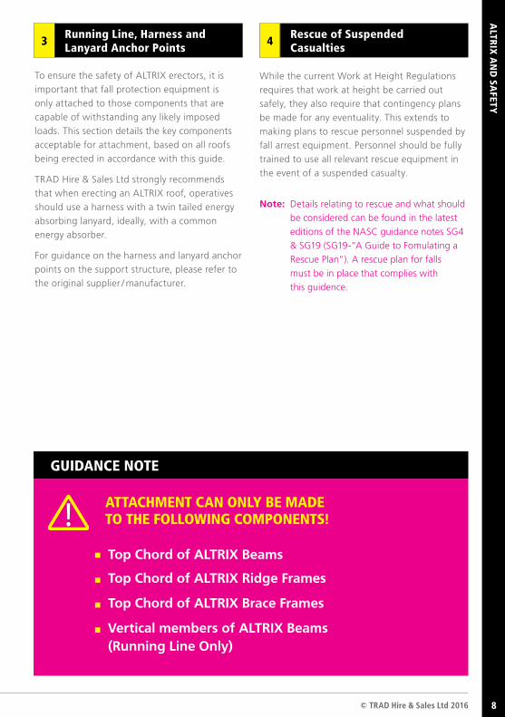
ATTACHMENT CAN ONLY BE MADE TO THE FOLLOWING COMPONENTS!
Top Chord of ALTRIX Beams
Top Chord of ALTRIX Ridge Frames
Top Chord of ALTRIX Brace Frames
Vertical members of ALTRIX Beams (Running Line Only)
GUIDANCE NOTE
8
ALTRIXTM User Guide8
MA
NU
AL H
AN
DLIN
G
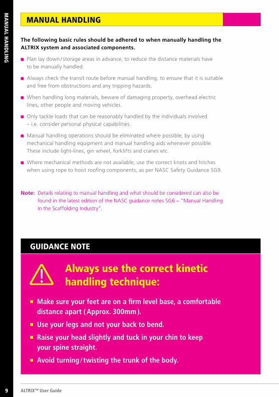
The following basic rules should be adhered to when manually handling the ALTRIX system and associated components.
Plan lay down / storage areas in advance, to reduce the distance materials have
to be manually handled.
Always check the transit route before manual handling, to ensure that it is suitable
and free from obstructions and any tripping hazards.
When handling long materials, beware of damaging property, overhead electric
lines, other people and moving vehicles.
Only tackle loads that can be reasonably handled by the individuals involved
– i.e. consider personal physical capabilities.
Manual handling operations should be eliminated where possible, by using
mechanical handling equipment and manual handling aids whenever possible.
These include light-lines, gin wheel, forklifts and cranes etc.
Where mechanical methods are not available, use the correct knots and hitches
when using rope to hoist roofing components, as per NASC Safety Guidance SG9.
Note: Details relating to manual handling and what should be considered can also be
found in the latest edition of the NASC guidance notes SG6 – “Manual Handling
in the Scaffolding Industry”.
Make sure your feet are on a firm level base, a comfortable distance apart ( Approx. 300mm ).
Use your legs and not your back to bend.
Raise your head slightly and tuck in your chin to keep your spine straight.
Avoid turning / twisting the trunk of the body.
Always use the correct kinetic handling technique:
GUIDANCE NOTE
MANUAL HANDLING
9
© TRAD Hire & Sales Ltd 2016 9
SAFETY
ON
SITE
As is the case with any scaffold, only trained and authorised scaffold operatives should carry out the erection, dismantling or modification of a ALTRIX structure. Consideration must always be given to those that may be affected by the works being carried out. To ensure that the highest standards of safety performance are maintained, consideration should be given to the following:
All roofing projects should be designed by
a temporary works / scaffold design engineer,
who is competent in the design
of temporary roofs.
A copy of drawings and calculations must
be kept on site.
A Safe System of Work should be drawn
up for the project and documented in
the site specific Risk Assessment / Method
Statement (RAMS).
A visual check of the supporting scaffold,
including roof support beams / ledgers,
must be carried out prior to commencing
roof erection to ensure the structure is
built to the engineer’s design.
A safe means of access to the level where
the roof is to be installed.
A sufficient means of protection and safe
system of work adopted. Work platforms
must be fully boarded and guard-railed, or
some other means of fall prevention / arrest
must be in place.
All ALTRIX roofs require adequate bracing,
none should be removed without giving
consideration to firstly installing alternative
bracing, to ensure the continued safety of
the roof (further design may be required).
All ALTRIX roofs must be erected in strict
accordance with this user guide. Any
configurations outside of this guide must
be referred to a person competent in the
design of ALTRIX.
Any unauthorised interference should be
immediately reported to site management,
with any incomplete or unsafe parts of the
roof or supporting scaffold being clearly
marked and access restricted.
All ALTRIX components require visual
inspection before use. No damaged
equipment should be used within the
structure. Any equipment found damaged
should be immediately set aside in a
quarantined area, clearly marked and senior
management informed. Maintenance and
repair procedures should only be carried
out by qualified / approved personnel.
Always wear appropriate PPE such as twin
tailed energy absorbing lanyards, Hi-Vis
and eye protection where required.
1
2
3
4
5
7
6
8
9
10
SAFETY ON SITE
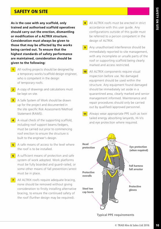
Head protection
Protective overalls
Steel toe cap boots
Eye protection (when required)
Full harness fall arrester
Protective gloves
Typical PPE requirements
11
10
ALTRIXTM User Guide10
Always ensure all who erect, adapt
and dismantle the roof are trained and
competent to do so.
Always ensure that risk assessments and
method statements have been carried out
and communicated to those concerned.
They should then be signed by all
operatives and the records retained.
Always ensure that there is adequate
storage for the materials.
Always ensure that there is clear access
to the work area and that the supporting
scaffold is sound and suitable for the roof.
Always work to current SG4 guidelines.
Always ensure loads are evenly distributed.
Always ensure scaffold inspections are
carried out and recorded as per current
legal requirements.
Always ensure that all defects are notified
to the site management immediately.
Never let untrained persons erect,
modify or dismantle the roof.
Never remove guardrails or toe boards.
Never remove bracing or tension bars
without prior approval.
Never tamper with beam support elements.
Never remove restrictions or warning signs
from the scaffold or roof structure.
Never undermine the support scaffold
by digging trenches underneath or near
the base.
Never add sheeting or netting onto the
support scaffold without prior approval.
Never use damaged materials.
Never allow unqualified / unapproved
personnel to repair damaged equipment.
Never load directly on to the access
scaffold’s working platform (always
use a loading tower).
Safety is no accident. Don’t risk it - if in doubt ask!
REMEMBER
The information given in this ALTRIX user guide relates solely to genuine ALTRIX equipment supplied by TRAD Hire & Sales Limited.
NeverAlways
GENERAL RULES FOR SAFETY
GEN
ERA
L RULES FO
R SAFETY
11
© TRAD Hire & Sales Ltd 2016 1112
COM
PON
ENTS
ALTRIXTM User Guide12
MA
IN C
OM
PO
NEN
TS
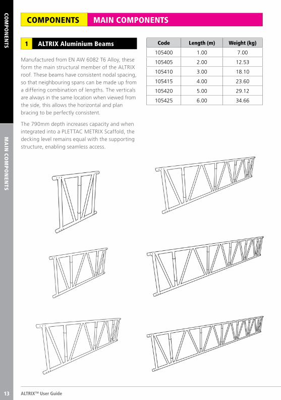
Manufactured from EN AW 6082 T6 Alloy, these form the main structural member of the ALTRIX roof. These beams have consistent nodal spacing, so that neighbouring spans can be made up from a differing combination of lengths. The verticals are always in the same location when viewed from the side, this allows the horizontal and plan bracing to be perfectly consistent.
The 790mm depth increases capacity and when integrated into a PLETTAC METRIX Scaffold, the decking level remains equal with the supporting structure, enabling seamless access.
ALTRIX Aluminium Beams1 Code Length (m) Weight (kg)
105400 1.00 7.00
105405 2.00 12.53
105410 3.00 18.10
105415 4.00 23.60
105420 5.00 29.12
105425 6.00 34.66
MAIN COMPONENTSCOMPONENTS
13
COM
PON
ENTS
© TRAD Hire & Sales Ltd 2016 13
MA
IN C
OM
PO
NEN
TS
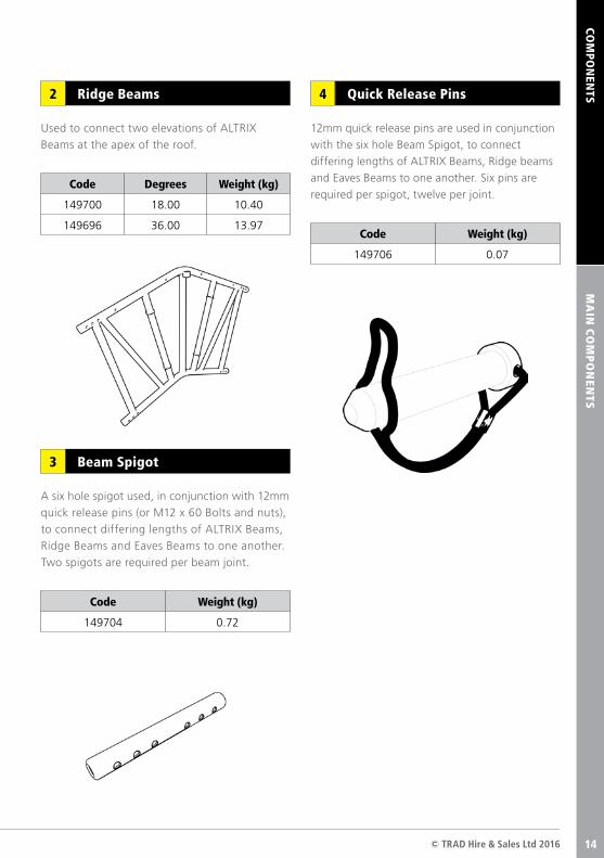
Used to connect two elevations of ALTRIX
Beams at the apex of the roof.
A six hole spigot used, in conjunction with 12mm
quick release pins (or M12 x 60 Bolts and nuts),
to connect differing lengths of ALTRIX Beams,
Ridge Beams and Eaves Beams to one another.
Two spigots are required per beam joint.
Code Degrees Weight (kg)
149700 18.00 10.40
149696 36.00 13.97
12mm quick release pins are used in conjunction
with the six hole Beam Spigot, to connect
differing lengths of ALTRIX Beams, Ridge beams
and Eaves Beams to one another. Six pins are
required per spigot, twelve per joint.
Ridge Beams2 Quick Release Pins4
Beam Spigot3
Code Weight (kg)
149706 0.07
Code Weight (kg)
149704 0.72
14
COM
PON
ENTS
ALTRIXTM User Guide14
MA
IN C
OM
PO
NEN
TS
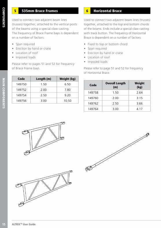
Used to connect two adjacent beam lines (trusses)
together, attached to the top and bottom chords
of the beams. Ends include a special claw casting
with track button. The frequency of Horizontal
Brace is dependent on a number of factors:
• Fixed to top or bottom chord
• Span required
• Erection by hand or crane
• Location of roof
• Imposed loads
Please refer to page 51 and 52 for frequency
of Horizontal Brace.
Used to connect two adjacent beam lines
(trusses) together, attached to the vertical posts
of the beams using a special claw casting.
The frequency of Brace Frame bays is dependent
on a number of factors:
• Span required
• Erection by hand or crane
• Location of roof
• Imposed loads
Please refer to pages 51 and 52 for frequency
of Brace Frame bays.
Horizontal Brace6535mm Brace Frames 5
Code Length (m) Weight (kg)
149750 1.50 6.50
149752 2.00 7.80
149754 2.50 9.20
149756 3.00 10.50
CodeOverall Length
(m)Weight
(kg)
149758 1.50 2.64
149760 2.00 3.15
149762 2.50 3.66
149764 3.00 4.17
15
COM
PON
ENTS
© TRAD Hire & Sales Ltd 2016 15
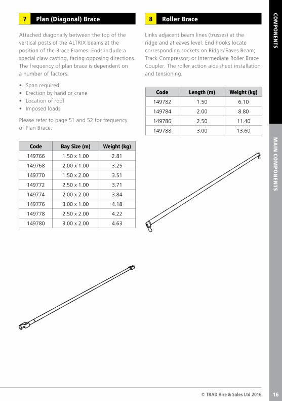
Attached diagonally between the top of the
vertical posts of the ALTRIX beams at the
position of the Brace Frames. Ends include a
special claw casting, facing opposing directions.
The frequency of plan brace is dependent on
a number of factors:
• Span required
• Erection by hand or crane
• Location of roof
• Imposed loads
Please refer to page 51 and 52 for frequency
of Plan Brace.
Links adjacent beam lines (trusses) at the
ridge and at eaves level. End hooks locate
corresponding sockets on Ridge / Eaves Beam;
Track Compressor; or Intermediate Roller Brace
Coupler. The roller action aids sheet installation
and tensioning.
Plan (Diagonal) Brace7 Roller Brace8
Code Bay Size (m) Weight (kg)
149766 1.50 x 1.00 2.81
149768 2.00 x 1.00 3.25
149770 1.50 x 2.00 3.51
149772 2.50 x 1.00 3.71
149774 2.00 x 2.00 3.84
149776 3.00 x 1.00 4.18
149778 2.50 x 2.00 4.22
149780 3.00 x 2.00 4.63
Code Length (m) Weight (kg)
149782 1.50 6.10
149784 2.00 8.80
149786 2.50 11.40
149788 3.00 13.60
MA
IN C
OM
PO
NEN
TS
16
COM
PON
ENTS
ALTRIXTM User Guide16
MA
IN C
OM
PO
NEN
TS
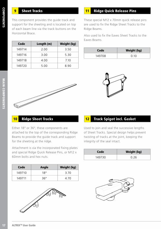
These special M12 x 70mm quick release pins
are used to fix the Ridge Sheet Tracks to the
Ridge Beams.
Also used to fix the Eaves Sheet Tracks to the
Eaves Beams.
This component provides the guide track and
support for the sheeting and is located on top
of each beam line via the track buttons on the
Horizontal Brace.
Code Length (m) Weight (kg)
149714 2.00 3.50
149716 3.00 5.30
149718 4.00 7.10
149720 5.00 8.90
Code Weight (kg)
149708 0.10
Sheet Tracks9 Ridge Quick Release Pins11
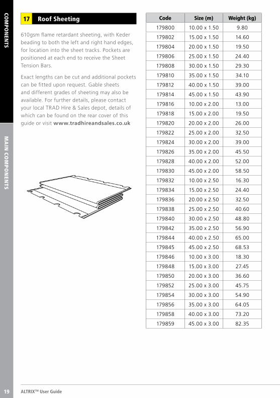
Used to join and seal the successive lengths
of Sheet Tracks. Special design helps prevent
twisting of tracks at the joint, keeping the
integrity of the seal intact.
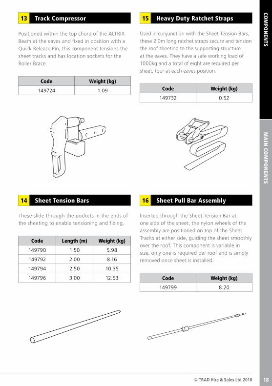
Either 18° or 36°, these components are
attached to the top of the corresponding Ridge
Beams to provide the guide track and support
for the sheeting at the ridge.
Attachment is via the incorporated fixing plates
and special Ridge Quick Release Pins, or M12 x
60mm bolts and hex nuts.
Code Angle Weight (kg)
149710 18° 3.70
149711 36° 4.70
Code Weight (kg)
149730 0.26
Ridge Sheet Tracks10 Track Spigot incl. Gasket12
17
COM
PON
ENTS
© TRAD Hire & Sales Ltd 2016 17
Code Length (m) Weight (kg)
149790 1.50 5.98
149792 2.00 8.16
149794 2.50 10.35
149796 3.00 12.53 Code Weight (kg)
149799 8.20
MA
IN C
OM
PO
NEN
TS
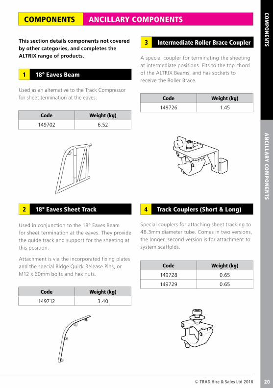
Positioned within the top chord of the ALTRIX
Beam at the eaves and fixed in position with a
Quick Release Pin, this component tensions the
sheet tracks and has location sockets for the
Roller Brace.
These slide through the pockets in the ends of
the sheeting to enable tensioning and fixing.
Inserted through the Sheet Tension Bar at
one side of the sheet, the nylon wheels of the
assembly are positioned on top of the Sheet
Tracks at either side, guiding the sheet smoothly
over the roof. This component is variable in
size, only one is required per roof and is simply
removed once sheet is installed.
Used in conjunction with the Sheet Tension Bars,
these 2.0m long ratchet straps secure and tension
the roof sheeting to the supporting structure
at the eaves. They have a safe working load of
1000kg and a total of eight are required per
sheet, four at each eaves position.
Heavy Duty Ratchet Straps15Track Compressor13
Sheet Tension Bars14 Sheet Pull Bar Assembly16
Code Weight (kg)
149732 0.52
Code Weight (kg)
149724 1.09
18
COM
PON
ENTS
ALTRIXTM User Guide18
MA
IN C
OM
PO
NEN
TS
Code Size (m) Weight (kg)
179800 10.00 x 1.50 9.80
179802 15.00 x 1.50 14.60
179804 20.00 x 1.50 19.50
179806 25.00 x 1.50 24.40
179808 30.00 x 1.50 29.30
179810 35.00 x 1.50 34.10
179812 40.00 x 1.50 39.00
179814 45.00 x 1.50 43.90
179816 10.00 x 2.00 13.00
179818 15.00 x 2.00 19.50
179820 20.00 x 2.00 26.00
179822 25.00 x 2.00 32.50
179824 30.00 x 2.00 39.00
179826 35.00 x 2.00 45.50
179828 40.00 x 2.00 52.00
179830 45.00 x 2.00 58.50
179832 10.00 x 2.50 16.30
179834 15.00 x 2.50 24.40
179836 20.00 x 2.50 32.50
179838 25.00 x 2.50 40.60
179840 30.00 x 2.50 48.80
179842 35.00 x 2.50 56.90
179844 40.00 x 2.50 65.00
179845 45.00 x 2.50 68.53
179846 10.00 x 3.00 18.30
179848 15.00 x 3.00 27.45
179850 20.00 x 3.00 36.60
179852 25.00 x 3.00 45.75
179854 30.00 x 3.00 54.90
179856 35.00 x 3.00 64.05
179858 40.00 x 3.00 73.20
179859 45.00 x 3.00 82.35
610gsm flame retardant sheeting, with Keder
beading to both the left and right hand edges,
for location into the sheet tracks. Pockets are
positioned at each end to receive the Sheet
Tension Bars.
Exact lengths can be cut and additional pockets
can be fitted upon request. Gable sheets
and different grades of sheeting may also be
available. For further details, please contact
your local TRAD Hire & Sales depot, details of
which can be found on the rear cover of this
guide or visit www.tradhireandsales.co.uk
Roof Sheeting17
19
AC
CESS C
OM
PO
NEN
TS
© TRAD Hire & Sales Ltd 2016 19
This section details components not covered by other categories, and completes the ALTRIX range of products.
ANCILLARY COMPONENTSCOMPONENTS
AN
CILLA
RY
CO
MP
ON
ENTS
COM
PON
ENTS
Used as an alternative to the Track Compressor
for sheet termination at the eaves.
A special coupler for terminating the sheeting
at intermediate positions. Fits to the top chord
of the ALTRIX Beams, and has sockets to
receive the Roller Brace.
Special couplers for attaching sheet tracking to
48.3mm diameter tube. Comes in two versions,
the longer, second version is for attachment to
system scaffolds.
Track Couplers (Short & Long)4
18° Eaves Beam1
Intermediate Roller Brace Coupler3
18° Eaves Sheet Track2
Code Weight (kg)
149702 6.52
Code Weight (kg)
149712 3.40
Used in conjunction to the 18° Eaves Beam
for sheet termination at the eaves. They provide
the guide track and support for the sheeting at
this position.
Attachment is via the incorporated fixing plates
and the special Ridge Quick Release Pins, or
M12 x 60mm bolts and hex nuts.
Code Weight (kg)
149726 1.45
Code Weight (kg)
149728 0.65
149729 0.65
20
ALTRIXTM User Guide20
COM
PON
ENTS
AN
CILLA
RY
CO
MP
ON
ENTS
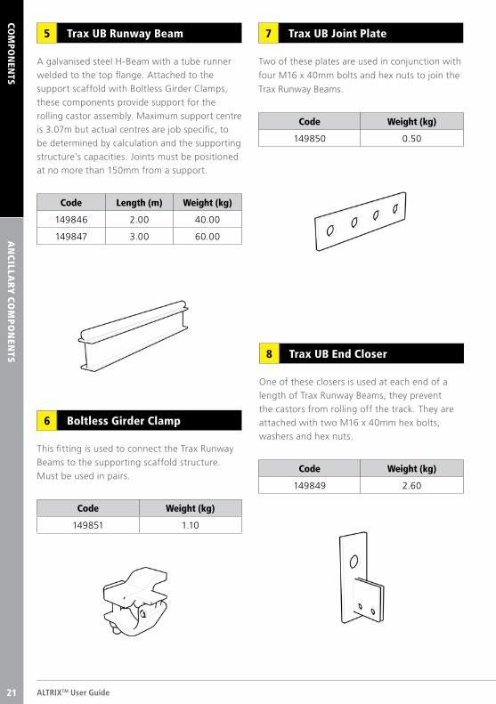
A galvanised steel H-Beam with a tube runner
welded to the top flange. Attached to the
support scaffold with Boltless Girder Clamps,
these components provide support for the
rolling castor assembly. Maximum support centre
is 3.07m but actual centres are job specific, to
be determined by calculation and the supporting
structure’s capacities. Joints must be positioned
at no more than 150mm from a support.
This fitting is used to connect the Trax Runway
Beams to the supporting scaffold structure.
Must be used in pairs.
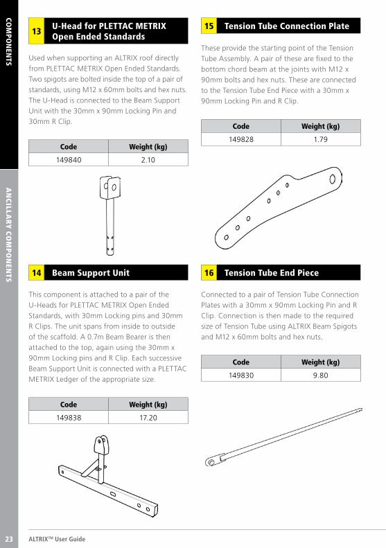
One of these closers is used at each end of a
length of Trax Runway Beams, they prevent
the castors from rolling off the track. They are
attached with two M16 x 40mm hex bolts,
washers and hex nuts.
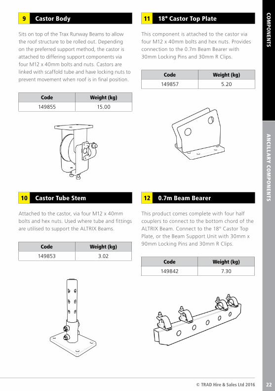
Two of these plates are used in conjunction with
four M16 x 40mm bolts and hex nuts to join the
Trax Runway Beams.
Trax UB Runway Beam5
Boltless Girder Clamp6
Trax UB End Closer8
Trax UB Joint Plate7
Code Length (m) Weight (kg)
149846 2.00 40.00
149847 3.00 60.00
Code Weight (kg)
149850 0.50
Code Weight (kg)
149851 1.10
Code Weight (kg)
149849 2.60
21
© TRAD Hire & Sales Ltd 2016 21
Sits on top of the Trax Runway Beams to allow
the roof structure to be rolled out. Depending
on the preferred support method, the castor is
attached to differing support components via
four M12 x 40mm bolts and nuts. Castors are
linked with scaffold tube and have locking nuts to
prevent movement when roof is in final position.
Attached to the castor, via four M12 x 40mm
bolts and hex nuts. Used where tube and fittings
are utilised to support the ALTRIX Beams.
This component is attached to the castor via
four M12 x 40mm bolts and hex nuts. Provides
connection to the 0.7m Beam Bearer with
30mm Locking Pins and 30mm R Clips.
Castor Body9
AN
CILLA
RY
CO
MP
ON
ENTS
COM
PON
ENTS
Code Weight (kg)
149853 3.02
Code Weight (kg)
149855 15.00
Code Weight (kg)
149857 5.20
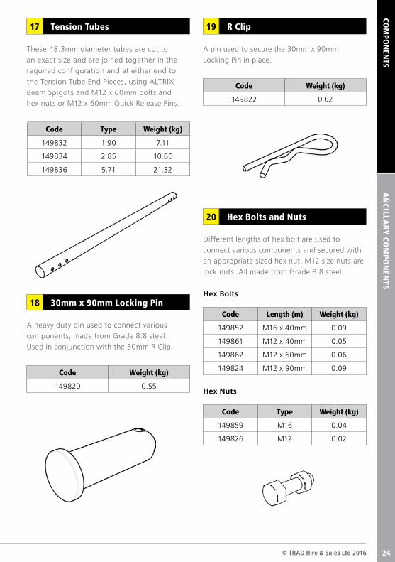
This product comes complete with four half
couplers to connect to the bottom chord of the
ALTRIX Beam. Connect to the 18° Castor Top
Plate, or the Beam Support Unit with 30mm x
90mm Locking Pins and 30mm R Clips.
Code Weight (kg)
149842 7.30
Castor Tube Stem10
18° Castor Top Plate11
0.7m Beam Bearer12
22
ALTRIXTM User Guide22
COM
PON
ENTS
AN
CILLA
RY
CO
MP
ON
ENTS
Used when supporting an ALTRIX roof directly
from PLETTAC METRIX Open Ended Standards.
Two spigots are bolted inside the top of a pair of
standards, using M12 x 60mm bolts and hex nuts.
The U-Head is connected to the Beam Support
Unit with the 30mm x 90mm Locking Pin and
30mm R Clip.
These provide the starting point of the Tension
Tube Assembly. A pair of these are fixed to the
bottom chord beam at the joints with M12 x
90mm bolts and hex nuts. These are connected
to the Tension Tube End Piece with a 30mm x
90mm Locking Pin and R Clip.
Connected to a pair of Tension Tube Connection
Plates with a 30mm x 90mm Locking Pin and R
Clip. Connection is then made to the required
size of Tension Tube using ALTRIX Beam Spigots
and M12 x 60mm bolts and hex nuts.
This component is attached to a pair of the
U-Heads for PLETTAC METRIX Open Ended
Standards, with 30mm Locking pins and 30mm
R Clips. The unit spans from inside to outside
of the scaffold. A 0.7m Beam Bearer is then
attached to the top, again using the 30mm x
90mm Locking pins and R Clip. Each successive
Beam Support Unit is connected with a PLETTAC
METRIX Ledger of the appropriate size.
Tension Tube Connection Plate15
Tension Tube End Piece16Beam Support Unit14
Code Weight (kg)
149828 1.79
U-Head for PLETTAC METRIX Open Ended Standards13
Code Weight (kg)
149840 2.10
Code Weight (kg)
149830 9.80
Code Weight (kg)
149838 17.20
23
COM
PON
ENTS
© TRAD Hire & Sales Ltd 2016 23
AN
CILLA
RY
CO
MP
ON
ENTS
A pin used to secure the 30mm x 90mm
Locking Pin in place.
These 48.3mm diameter tubes are cut to
an exact size and are joined together in the
required configuration and at either end to
the Tension Tube End Pieces, using ALTRIX
Beam Spigots and M12 x 60mm bolts and
hex nuts or M12 x 60mm Quick Release Pins.
A heavy duty pin used to connect various
components, made from Grade 8.8 steel.
Used in conjunction with the 30mm R Clip.
Different lengths of hex bolt are used to
connect various components and secured with
an appropriate sized hex nut. M12 size nuts are
lock nuts. All made from Grade 8.8 steel.
R Clip19Tension Tubes17
30mm x 90mm Locking Pin18
Hex Bolts and Nuts20
Code Type Weight (kg)
149832 1.90 7.11
149834 2.85 10.66
149836 5.71 21.32
Code Weight (kg)
149820 0.55
Code Weight (kg)
149822 0.02
Code Length (m) Weight (kg)
149852 M16 x 40mm 0.09
149861 M12 x 40mm 0.05
149862 M12 x 60mm 0.06
149824 M12 x 90mm 0.09
Code Type Weight (kg)
149859 M16 0.04
149826 M12 0.02
Hex Bolts
Hex Nuts
24
COM
PON
ENTS
ALTRIXTM User Guide24
BA
Y S
IZE CO
LOU
R C
OD
ING
BAY SIZE COLOUR CODINGCOMPONENTS
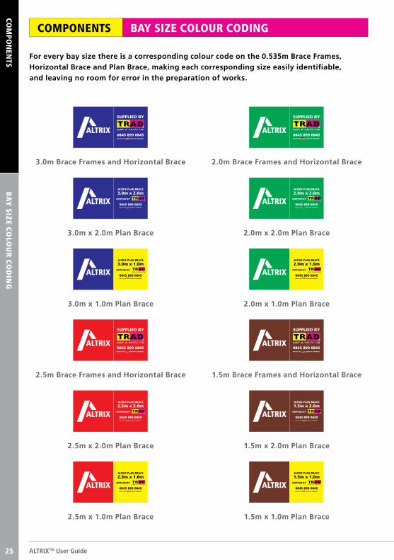
For every bay size there is a corresponding colour code on the 0.535m Brace Frames, Horizontal Brace and Plan Brace, making each corresponding size easily identifiable, and leaving no room for error in the preparation of works.
0845 899 0845
SUPPLIED BY
3.0m Brace Frames and Horizontal Brace
ALTRIX PLAN BRACE
3.0m x 2.0m
0845 899 0845
SUPPLIED BY
3.0m x 2.0m Plan Brace
ALTRIX PLAN BRACE
3.0m x 1.0m
0845 899 0845
SUPPLIED BY
3.0m x 1.0m Plan Brace
0845 899 0845
SUPPLIED BY
2.5m Brace Frames and Horizontal Brace
ALTRIX PLAN BRACE
2.5m x 2.0m
0845 899 0845
SUPPLIED BY
2.5m x 2.0m Plan Brace
ALTRIX PLAN BRACE
2.5m x 1.0m
0845 899 0845
SUPPLIED BY
2.5m x 1.0m Plan Brace
0845 899 0845
SUPPLIED BY
2.0m Brace Frames and Horizontal Brace
ALTRIX PLAN BRACE
2.0m x 2.0m
0845 899 0845
SUPPLIED BY
2.0m x 2.0m Plan Brace
ALTRIX PLAN BRACE
2.0m x 1.0m
0845 899 0845
SUPPLIED BY
2.0m x 1.0m Plan Brace
0845 899 0845
SUPPLIED BY
1.5m Brace Frames and Horizontal Brace
ALTRIX PLAN BRACE
1.5m x 2.0m
0845 899 0845
SUPPLIED BY
1.5m x 2.0m Plan Brace
ALTRIX PLAN BRACE
1.5m x 1.0m
0845 899 0845
SUPPLIED BY
1.5m x 1.0m Plan Brace
25
© TRAD Hire & Sales Ltd 2016 25
ERECTIO
N &
DISM
AN
TLING
GU
IDA
NC
EB
AS
IC ER
ECTIO
N P
RO
CED
UR
E
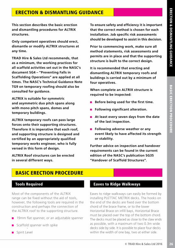
This section describes the basic erection and dismantling procedures for ALTRIX structures.
Only competent operatives should erect, dismantle or modify ALTRIX structures at any time.
TRAD Hire & Sales Ltd recommends, that as a minimum, the working practices for all scaffold activities set out in the NASC’s document SG4 – “Preventing Falls in Scaffolding Operations” are applied at all times. The NASC’s Technical Guidance Note TG9 on temporary roofing should also be consulted for guidance.
ALTRIX is suitable for symmetric and asymmetric duo pitch spans along with mono pitch spans, domes and temporary buildings.
ALTRIX temporary roofs can pass large forces onto their supporting structures. Therefore it is imperative that each roof, and supporting structure is designed and certified by an appropriately qualified temporary works engineer, who is fully versed in this form of design.
ALTRIX Roof structures can be erected in several different ways.
To ensure safety and efficiency it is important that the correct method is chosen for each installation. Job specific risk assessments should be developed to assist in this decision.
Prior to commencing work, make sure all method statements, risk assessments and permits are in place and that the supporting structure is built to the correct design.
It is recommended that erecting and dismantling ALTRIX temporary roofs and buildings is carried out by a minimum of four operatives.
When complete an ALTRIX structure is required to be inspected:
Before being used for the first time.
Following significant alteration.
At least every seven days from the date of the last inspection.
Following adverse weather or any event likely to have affected its strength or stability.
Further advice on inspection and handover requirements can be found in the current edition of the NASC’s publication SG35 “Handover of Scaffold Structures”.
ERECTION & DISMANTLING GUIDANCE
BASIC ERECTION PROCEDURE
Most of the components of the ALTRIX range can be fixed without the aid of tools, however, the following tools are required in the construction and perhaps the connection of the ALTRIX roof to the supporting structure.
19mm flat spanner, or an adjustable spanner
Scaffold spanner with spike
Spirit Level
Eaves to ridge walkways can easily be formed by installing PLETTAC METRIX decks. The hooks on the end of the decks are fixed over the bottom chord of the brace frame, or to the lower Horizontal Brace on infill bays, Horizontal Brace must be placed over the top of the bottom chord. The decks must be placed as close to the claw ends as possible, with a maximum of two 0.3m wide decks side by side. It is possible to place four decks within the width of one bay, two at either side.
Tools Required Eaves to Ridge Walkways
26
ALTRIXTM User Guide26
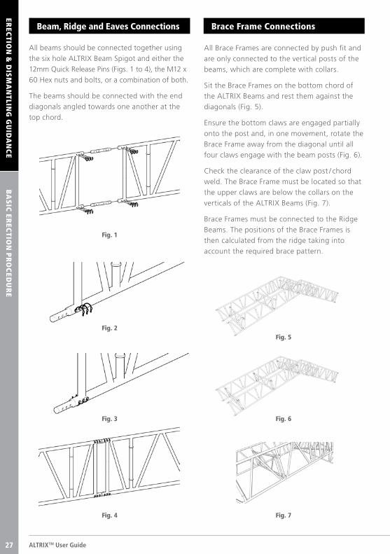
All beams should be connected together using
the six hole ALTRIX Beam Spigot and either the
12mm Quick Release Pins (Figs. 1 to 4), the M12 x
60 Hex nuts and bolts, or a combination of both.
The beams should be connected with the end
diagonals angled towards one another at the
top chord.
Beam, Ridge and Eaves Connections
EREC
TION
& D
ISM
AN
TLING
GU
IDA
NC
EB
AS
IC ER
ECTIO
N P
RO
CED
UR
E
All Brace Frames are connected by push fit and
are only connected to the vertical posts of the
beams, which are complete with collars.
Sit the Brace Frames on the bottom chord of
the ALTRIX Beams and rest them against the
diagonals (Fig. 5).
Ensure the bottom claws are engaged partially
onto the post and, in one movement, rotate the
Brace Frame away from the diagonal until all
four claws engage with the beam posts (Fig. 6).
Check the clearance of the claw post / chord
weld. The Brace Frame must be located so that
the upper claws are below the collars on the
verticals of the ALTRIX Beams (Fig. 7).
Brace Frames must be connected to the Ridge
Beams. The positions of the Brace Frames is
then calculated from the ridge taking into
account the required brace pattern.
Brace Frame Connections
Fig. 1
Fig. 2Fig. 5
Fig. 3 Fig. 6
Fig. 4 Fig. 7
27
AC
CESS C
OM
PO
NEN
TS
© TRAD Hire & Sales Ltd 2016 27
EREC
TION
& D
ISM
AN
TLING
GU
IDA
NC
E
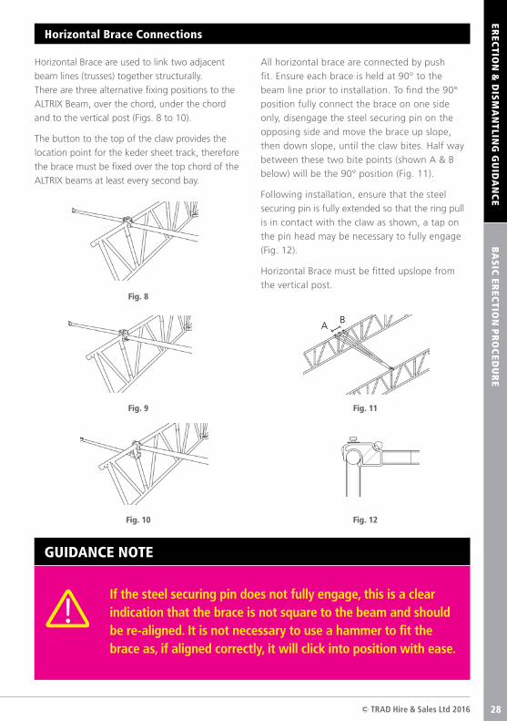
All horizontal brace are connected by push
fit. Ensure each brace is held at 90° to the
beam line prior to installation. To find the 90°
position fully connect the brace on one side
only, disengage the steel securing pin on the
opposing side and move the brace up slope,
then down slope, until the claw bites. Half way
between these two bite points (shown A & B
below) will be the 90° position (Fig. 11).
Following installation, ensure that the steel
securing pin is fully extended so that the ring pull
is in contact with the claw as shown, a tap on
the pin head may be necessary to fully engage
(Fig. 12).
Horizontal Brace must be fitted upslope from
the vertical post.
Horizontal Brace are used to link two adjacent
beam lines (trusses) together structurally.
There are three alternative fixing positions to the
ALTRIX Beam, over the chord, under the chord
and to the vertical post (Figs. 8 to 10).
The button to the top of the claw provides the
location point for the keder sheet track, therefore
the brace must be fixed over the top chord of the
ALTRIX beams at least every second bay.
Horizontal Brace Connections
BA
SIC
EREC
TION
PR
OC
EDU
RE
GUIDANCE NOTE
If the steel securing pin does not fully engage, this is a clear indication that the brace is not square to the beam and should be re-aligned. It is not necessary to use a hammer to fit the brace as, if aligned correctly, it will click into position with ease.
Fig. 8
Fig. 11
AB
Fig. 12
Fig. 9
Fig. 10
28
AC
CESS C
OM
PO
NEN
TS
ALTRIXTM User Guide28
EREC
TION
& D
ISM
AN
TLING
GU
IDA
NC
EB
AS
IC ER
ECTIO
N P
RO
CED
UR
E
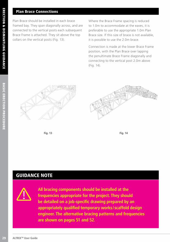
Plan Brace should be installed in each brace
framed bay. They span diagonally across, and are
connected to the vertical posts each subsequent
Brace Frame is attached. They sit above the top
collars on the vertical posts (Fig. 13).
Plan Brace Connections
Fig. 13
Where the Brace Frame spacing is reduced
to 1.0m to accommodate at the eaves, it is
preferable to use the appropriate 1.0m Plan
Brace size. If this size of brace is not available,
it is possible to use the 2.0m brace.
Connection is made at the lower Brace Frame
position, with the Plan Brace over lapping
the penultimate Brace Frame diagonally and
connecting to the vertical post 2.0m above
(Fig. 14).
Fig. 14
GUIDANCE NOTE
All bracing components should be installed at the frequencies appropriate for the project. They should be detailed on a job-specific drawing prepared by an appropriately qualified temporary works / scaffold design engineer. The alternative bracing patterns and frequencies are shown on pages 51 and 52.
29
COM
PON
ENTS
AC
CESS C
OM
PO
NEN
TS
© TRAD Hire & Sales Ltd 2016 29
EREC
TION
& D
ISM
AN
TLING
GU
IDA
NC
EB
AS
IC ER
ECTIO
N P
RO
CED
UR
E
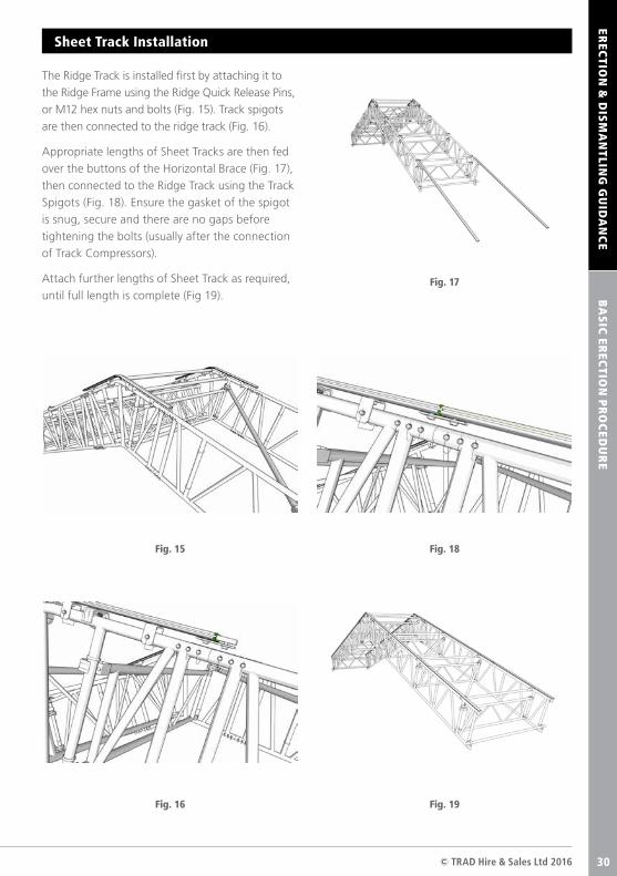
The Ridge Track is installed first by attaching it to
the Ridge Frame using the Ridge Quick Release Pins,
or M12 hex nuts and bolts (Fig. 15). Track spigots
are then connected to the ridge track (Fig. 16).
Appropriate lengths of Sheet Tracks are then fed
over the buttons of the Horizontal Brace (Fig. 17),
then connected to the Ridge Track using the Track
Spigots (Fig. 18). Ensure the gasket of the spigot
is snug, secure and there are no gaps before
tightening the bolts (usually after the connection
of Track Compressors).
Attach further lengths of Sheet Track as required,
until full length is complete (Fig 19).
Sheet Track Installation
Fig. 15
Fig. 17
Fig. 18
Fig. 19Fig. 16
30
COM
PON
ENTS
AC
CESS C
OM
PO
NEN
TS
ALTRIXTM User Guide30
EREC
TION
& D
ISM
AN
TLING
GU
IDA
NC
EB
AS
IC ER
ECTIO
N P
RO
CED
UR
E
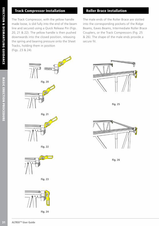
The male ends of the Roller Brace are slotted
into the corresponding pockets of the Ridge
Beams, Eaves Beams, Intermediate Roller Brace
Couplers, or the Track Compressors (Fig. 25
& 26). The shape of the male ends provide a
secure fit.
Roller Brace Installation
The Track Compressor, with the yellow handle
made loose, is slid fully into the end of the beam
line and secured using a Quick Release Pin (Figs.
20, 21 & 22). The yellow handle is then pushed
downwards into the closed position, releasing
the spring and bearing pressure onto the Sheet
Tracks, holding them in position
(Figs. 23 & 24).
Track Compressor Installation
Fig. 25
Fig. 26
Fig. 21
Fig. 22
Fig. 23
Fig. 24
Fig. 20
31
COM
PON
ENTS
AC
CESS C
OM
PO
NEN
TS
© TRAD Hire & Sales Ltd 2016 31
EREC
TION
& D
ISM
AN
TLING
GU
IDA
NC
EB
AS
IC ER
ECTIO
N P
RO
CED
UR
E
Prevailing weather conditions may determine
whether it is safe to commence the sheeting
operation, as loose sheets are vulnerable to
high winds.
Sheeting is ideally carried out by four operatives,
two on each side of the roof.
Two ropes must be deployed over the roof from one
side to the other, prior to commencing sheeting.
Ensure sheets are leaf-folded, clean and fit for use.
Visually check the keder bead for cuts / damage.
Do not use if damaged. Place the sheeting on the
boarded lift directly below the bay to be sheeted.
Insert the tension tube through the pockets of the
leading edge of the sheet, attach the previously
deployed ropes securely to the tension tube at the
two outer cutaways.
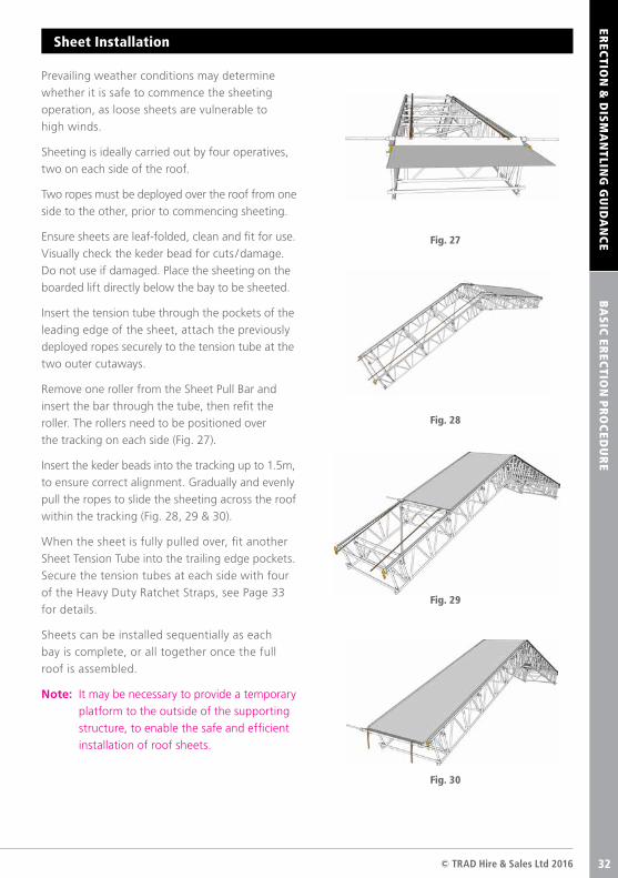
Remove one roller from the Sheet Pull Bar and
insert the bar through the tube, then refit the
roller. The rollers need to be positioned over
the tracking on each side (Fig. 27).
Insert the keder beads into the tracking up to 1.5m,
to ensure correct alignment. Gradually and evenly
pull the ropes to slide the sheeting across the roof
within the tracking (Fig. 28, 29 & 30).
When the sheet is fully pulled over, fit another
Sheet Tension Tube into the trailing edge pockets.
Secure the tension tubes at each side with four
of the Heavy Duty Ratchet Straps, see Page 33
for details.
Sheets can be installed sequentially as each
bay is complete, or all together once the full
roof is assembled.
Note: It may be necessary to provide a temporary
platform to the outside of the supporting
structure, to enable the safe and efficient
installation of roof sheets.
Sheet Installation
Fig. 27
Fig. 28
Fig. 29
Fig. 30
32
ALTRIXTM User Guide32
BA
SIC
EREC
TION
PR
OC
EDU
RE
EREC
TION
& D
ISM
AN
TLING
GU
IDA
NC
E
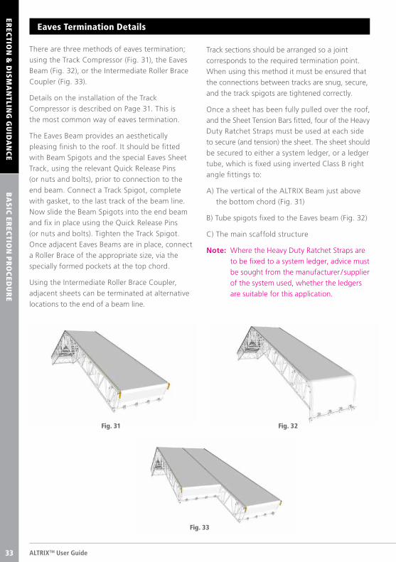
Eaves Termination Details
There are three methods of eaves termination;
using the Track Compressor (Fig. 31), the Eaves
Beam (Fig. 32), or the Intermediate Roller Brace
Coupler (Fig. 33).
Details on the installation of the Track
Compressor is described on Page 31. This is
the most common way of eaves termination.
The Eaves Beam provides an aesthetically
pleasing finish to the roof. It should be fitted
with Beam Spigots and the special Eaves Sheet
Track, using the relevant Quick Release Pins
(or nuts and bolts), prior to connection to the
end beam. Connect a Track Spigot, complete
with gasket, to the last track of the beam line.
Now slide the Beam Spigots into the end beam
and fix in place using the Quick Release Pins
(or nuts and bolts). Tighten the Track Spigot.
Once adjacent Eaves Beams are in place, connect
a Roller Brace of the appropriate size, via the
specially formed pockets at the top chord.
Using the Intermediate Roller Brace Coupler,
adjacent sheets can be terminated at alternative
locations to the end of a beam line.
Track sections should be arranged so a joint
corresponds to the required termination point.
When using this method it must be ensured that
the connections between tracks are snug, secure,
and the track spigots are tightened correctly.
Once a sheet has been fully pulled over the roof,
and the Sheet Tension Bars fitted, four of the Heavy
Duty Ratchet Straps must be used at each side
to secure (and tension) the sheet. The sheet should
be secured to either a system ledger, or a ledger
tube, which is fixed using inverted Class B right
angle fittings to:
A) The vertical of the ALTRIX Beam just above
the bottom chord (Fig. 31)
B) Tube spigots fixed to the Eaves beam (Fig. 32)
C) The main scaffold structure
Note: Where the Heavy Duty Ratchet Straps are
to be fixed to a system ledger, advice must
be sought from the manufacturer / supplier
of the system used, whether the ledgers
are suitable for this application.
Fig. 32Fig. 31
Fig. 33
33
© TRAD Hire & Sales Ltd 2016 33
EREC
TION
& D
ISM
AN
TLING
GU
IDA
NC
ES
PAN
TYP
ES
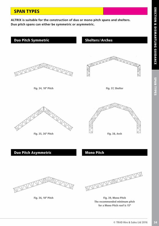
SPAN TYPES
ALTRIX is suitable for the construction of duo or mono pitch spans and shelters. Duo pitch spans can either be symmetric or asymmetric.
Fig. 34, 18° Pitch Fig. 37, Shelter
Fig. 35, 36° Pitch
Fig. 36, 18° Pitch
Fig. 38, Arch
Fig. 39, Mono PitchThe recommended minimum pitch
for a Mono Pitch roof is 15°
Duo Pitch Symmetric
Duo Pitch Asymmetric
Shelters / Arches
Mono Pitch
34
ALTRIXTM User Guide34
SCA
FFOLD
CO
NN
ECTIO
NS
EREC
TION
& D
ISM
AN
TLING
GU
IDA
NC
E
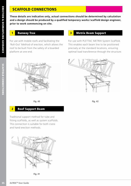
SCAFFOLD CONNECTIONS
These details are indicative only, actual connections should be determined by calculation and a design should be produced by a qualified temporary works / scaffold design engineer, prior to work commencing on site.
For use with mobile roofs and facilitating the
‘Roll-Out’ Method of erection, which allows the
roof to be built from the safety of a boarded
platform at one end.
For use with PLETTAC METRIX System Scaffold.
This enables each beam line to be positioned
precisely at the standard locations, ensuring
optimal load transference through the structure.
Traditional support method for tube and
fitting scaffolds, as well as system scaffolds.
This connection is suitable for both crane
and hand erection methods.
Runway Trax1 Metrix Beam Support3
Roof Support Beam2
Fig. 40 Fig. 42
Fig. 41
35
© TRAD Hire & Sales Ltd 2016 35
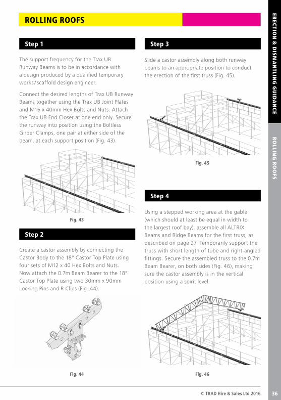
The support frequency for the Trax UB
Runway Beams is to be in accordance with
a design produced by a qualified temporary
works / scaffold design engineer.
Connect the desired lengths of Trax UB Runway
Beams together using the Trax UB Joint Plates
and M16 x 40mm Hex Bolts and Nuts. Attach
the Trax UB End Closer at one end only. Secure
the runway into position using the Boltless
Girder Clamps, one pair at either side of the
beam, at each support position (Fig. 43).
Slide a castor assembly along both runway
beams to an appropriate position to conduct
the erection of the first truss (Fig. 45).
Using a stepped working area at the gable
(which should at least be equal in width to
the largest roof bay), assemble all ALTRIX
Beams and Ridge Beams for the first truss, as
described on page 27. Temporarily support the
truss with short length of tube and right-angled
fittings. Secure the assembled truss to the 0.7m
Beam Bearer, on both sides (Fig. 46), making
sure the castor assembly is in the vertical
position using a spirit level.
Create a castor assembly by connecting the
Castor Body to the 18° Castor Top Plate using
four sets of M12 x 40 Hex Bolts and Nuts.
Now attach the 0.7m Beam Bearer to the 18°
Castor Top Plate using two 30mm x 90mm
Locking Pins and R Clips (Fig. 44).
EREC
TION
& D
ISM
AN
TLING
GU
IDA
NC
ER
OLLIN
G R
OO
FS
ROLLING ROOFS
Fig. 43
Fig. 45
Fig. 46Fig. 44
Step 1 Step 3
Step 4
Step 2
36
ALTRIXTM User Guide36
RO
LLING
RO
OFS
EREC
TION
& D
ISM
AN
TLING
GU
IDA
NC
E
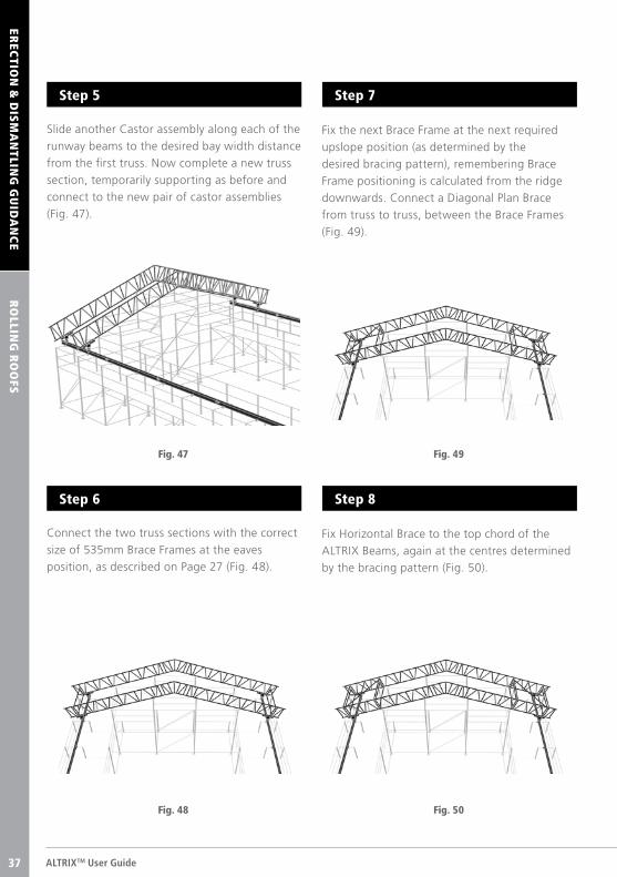
Slide another Castor assembly along each of the
runway beams to the desired bay width distance
from the first truss. Now complete a new truss
section, temporarily supporting as before and
connect to the new pair of castor assemblies
(Fig. 47).
Fix the next Brace Frame at the next required
upslope position (as determined by the
desired bracing pattern), remembering Brace
Frame positioning is calculated from the ridge
downwards. Connect a Diagonal Plan Brace
from truss to truss, between the Brace Frames
(Fig. 49).
Fix Horizontal Brace to the top chord of the
ALTRIX Beams, again at the centres determined
by the bracing pattern (Fig. 50).
Connect the two truss sections with the correct
size of 535mm Brace Frames at the eaves
position, as described on Page 27 (Fig. 48).
Fig. 47 Fig. 49
Fig. 50Fig. 48
Step 5 Step 7
Step 8Step 6
37
© TRAD Hire & Sales Ltd 2016 37
RO
LLING
RO
OFS
EREC
TION
& D
ISM
AN
TLING
GU
IDA
NC
E
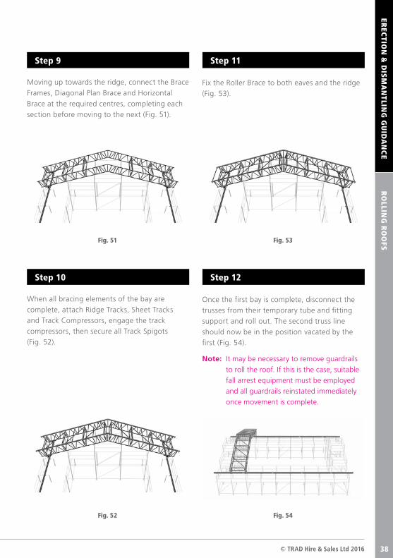
Moving up towards the ridge, connect the Brace
Frames, Diagonal Plan Brace and Horizontal
Brace at the required centres, completing each
section before moving to the next (Fig. 51).
Fix the Roller Brace to both eaves and the ridge
(Fig. 53).
Once the first bay is complete, disconnect the
trusses from their temporary tube and fitting
support and roll out. The second truss line
should now be in the position vacated by the
first (Fig. 54).
Note: It may be necessary to remove guardrails
to roll the roof. If this is the case, suitable
fall arrest equipment must be employed
and all guardrails reinstated immediately
once movement is complete.
When all bracing elements of the bay are
complete, attach Ridge Tracks, Sheet Tracks
and Track Compressors, engage the track
compressors, then secure all Track Spigots
(Fig. 52).
Fig. 51 Fig. 53
Fig. 54Fig. 52
Step 9 Step 11
Step 12Step 10
38
ALTRIXTM User Guide38
Fig. 58
Fig. 59
RO
LLING
RO
OFS
EREC
TION
& D
ISM
AN
TLING
GU
IDA
NC
E
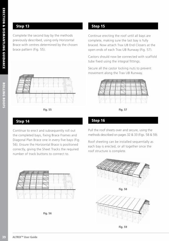
Complete the second bay by the methods
previously described, using only Horizontal
Brace with centres determined by the chosen
brace pattern (Fig. 55).
Continue erecting the roof until all bays are
complete, making sure the last bay is fully
braced. Now attach Trax UB End Closers at the
open ends of each Trax UB Runway (Fig. 57).
Castors should now be connected with scaffold
tube fixed using the integral fittings.
Secure all the castor locking nuts to prevent
movement along the Trax UB Runway.
Pull the roof sheets over and secure, using the
methods described on pages 32 & 33 (Figs. 58 & 59).
Roof sheeting can be installed sequentially as
each bay is erected, or all together once the
roof structure is complete.
Continue to erect and subsequently roll out
the completed bays, fixing Brace Frames and
Diagonal Plan Brace one in every five bays (Fig.
56). Ensure the Horizontal Brace is positioned
correctly, giving the Sheet Tracks the required
number of track buttons to connect to.
Fig. 55 Fig. 57
Fig. 56
Step 13 Step 15
Step 16Step 14
39
© TRAD Hire & Sales Ltd 2016 39
EREC
TION
BY
CR
AN
EER
ECTIO
N &
DIS
MA
NTLIN
G G
UID
AN
CE
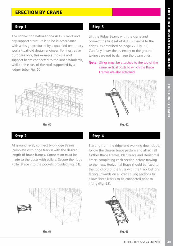
The connection between the ALTRIX Roof and
any support structure is to be in accordance
with a design produced by a qualified temporary
works / scaffold design engineer. For illustrative
purposes only, this example shows a roof
support beam connected to the inner standards,
whilst the eaves of the roof supported by a
ledger tube (Fig. 60).
Lift the Ridge Beams with the crane and
connect the first set of ALTRIX Beams to the
ridges, as described on page 27 (Fig. 62).
Carefully lower the assembly to the ground
taking care not to damage the beam ends.
Note: Slings must be attached to the top of the
same vertical posts to which the Brace
Frames are also attached.
Starting from the ridge and working downslope,
follow the chosen brace pattern and attach all
further Brace Frames, Plan Brace and Horizontal
Brace, completing each section before moving
to the next. Horizontal Brace should be fixed to
the top chord of the truss with the track buttons
facing upwards on all crane slung sections to
allow Sheet Tracks to be connected prior to
lifting (Fig. 63).
At ground level, connect two Ridge Beams
(complete with ridge tracks) with the desired
length of brace frames. Connection must be
made to the posts with collars. Secure the ridge
Roller Brace into the pockets provided (Fig. 61).
Fig. 60 Fig. 62
Fig. 63Fig. 61
Step 1 Step 3
Step 4Step 2
ERECTION BY CRANE
40
ALTRIXTM User Guide40
Fig. 64
EREC
TION
BY
CR
AN
EER
ECTIO
N &
DIS
MA
NTLIN
G G
UID
AN
CE
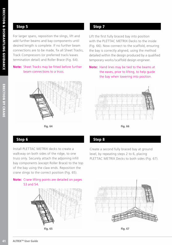
For larger spans, reposition the slings, lift and
add further beams and bay components until
desired length is complete. If no further beam
connections are to be made, fix all Sheet Tracks,
Track Compressors (or preferred track / eaves
termination detail) and Roller Brace (Fig. 64).
Note: Sheet Tracks may be fitted before further
beam connections to a truss.
Lift the first fully braced bay into position
with the PLETTAC METRIX Decks to the inside
(Fig. 66). Now connect to the scaffold, ensuring
the bay is correctly aligned, using the method
detailed within the design produced by a qualified
temporary works / scaffold design engineer.
Note: Hand lines may be tied to the beams at
the eaves, prior to lifting, to help guide
the bay when lowering into position.
Create a second fully braced bay at ground
level, by repeating steps 2 to 6, placing
PLETTAC METRIX Decks to both sides (Fig. 67).
Install PLETTAC METRIX decks to create a
walkway on both sides of the ridge, to one
truss only. Securely attach the adjoining infill
bay components (except Roller Brace) to the top
of the bay using the claw ends. Reposition the
crane slings to the correct position (Fig. 65).
Note: Crane lifting points are detailed on pages
53 and 54.
Fig. 66
Fig. 67Fig. 65
Step 5 Step 7
Step 8Step 6
41
© TRAD Hire & Sales Ltd 2016 41
Fig. 69
EREC
TION
BY
CR
AN
EER
ECTIO
N &
DIS
MA
NTLIN
G G
UID
AN
CE
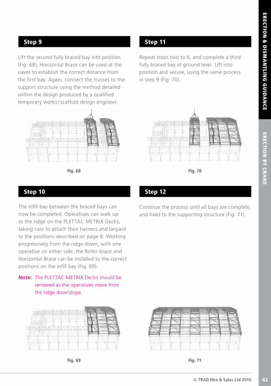
Lift the second fully braced bay into position
(Fig. 68), Horizontal Brace can be used at the
eaves to establish the correct distance from
the first bay. Again, connect the trusses to the
support structure using the method detailed
within the design produced by a qualified
temporary works / scaffold design engineer.
Repeat steps two to 6, and complete a third
fully braced bay at ground level. Lift into
position and secure, using the same process
in step 9 (Fig. 70).
Continue the process until all bays are complete,
and fixed to the supporting structure (Fig. 71).
The infill bay between the braced bays can
now be completed. Operatives can walk up
to the ridge on the PLETTAC METRIX Decks,
taking care to attach their harness and lanyard
to the positions described on page 8. Working
progressively from the ridge down, with one
operative on either side, the Roller brace and
Horizontal Brace can be installed to the correct
positions on the infill bay (Fig. 69).
Note: The PLETTAC METRIX Decks should be
removed as the operatives move from
the ridge downslope.
Fig. 71
Step 9 Step 11
Step 12Step 10
Fig. 68 Fig. 70
42
ALTRIXTM User Guide42
EREC
TION
BY
CR
AN
EER
ECTIO
N &
DIS
MA
NTLIN
G G
UID
AN
CE
Fig. 72
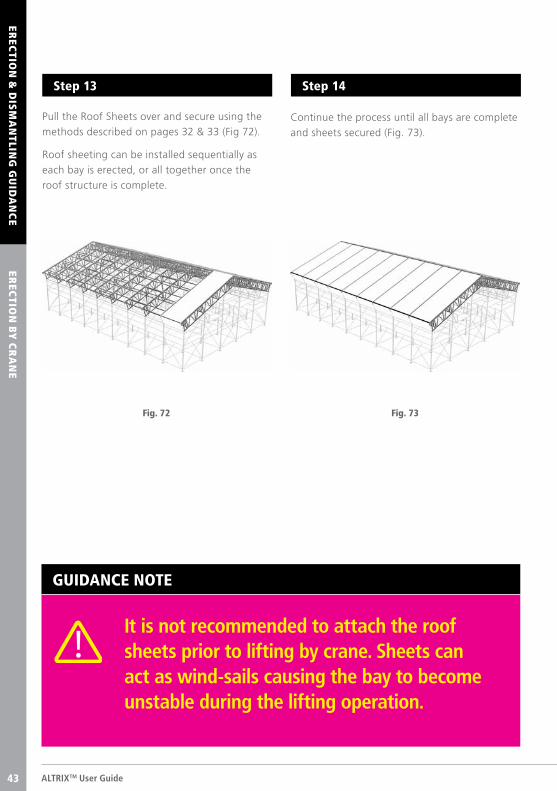
Pull the Roof Sheets over and secure using the
methods described on pages 32 & 33 (Fig 72).
Roof sheeting can be installed sequentially as
each bay is erected, or all together once the
roof structure is complete.
Continue the process until all bays are complete
and sheets secured (Fig. 73).
Fig. 73
Step 13 Step 14
GUIDANCE NOTE
It is not recommended to attach the roof sheets prior to lifting by crane. Sheets can act as wind-sails causing the bay to become unstable during the lifting operation.
43
© TRAD Hire & Sales Ltd 2016 43
EREC
TION
BY
HA
ND
EREC
TION
& D
ISM
AN
TLING
GU
IDA
NC
E
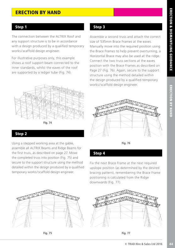
The connection between the ALTRIX Roof and
any support structure is to be in accordance
with a design produced by a qualified temporary
works / scaffold design engineer.
For illustrative purposes only, this example
shows a roof support beam connected to the
inner standards, whilst the eaves of the roof
are supported by a ledger tube (Fig. 74).
Assemble a second truss and attach the correct
size of 535mm Brace Frames at the eaves.
Manually move into the required position using
the Brace Frames to help prevent overturning, a
Horizontal Brace may also be used at the ridge.
Connect the two truss sections at the eaves
position with the Brace Frames as described on
Page 27 (Fig. 76). Again, secure to the support
structure using the method detailed within
the design produced by a qualified temporary
works / scaffold design engineer.
Fix the next Brace Frame at the next required
upslope position (as determined by the desired
bracing pattern), remembering the Brace Frame
positioning is calculated from the Ridge
downwards (Fig. 77).
Using a stepped working area at the gable,
assemble all ALTRIX Beams and Ridge Beams for
the first truss, as described on page 27. Move
the completed truss into position (Fig. 75) and
secure to the support structure using the method
detailed within the design produced by a qualified
temporary works / scaffold design engineer.
Fig. 74
Fig. 76
Fig. 77Fig. 75
Step 1 Step 3
Step 4
Step 2
ERECTION BY HAND
44
ALTRIXTM User Guide44
EREC
TION
BY
HA
ND
EREC
TION
& D
ISM
AN
TLING
GU
IDA
NC
E
Fig. 78
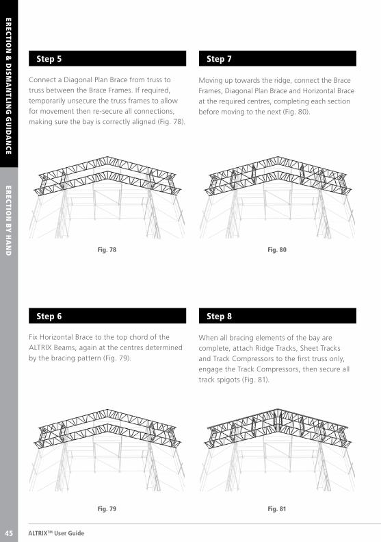
Connect a Diagonal Plan Brace from truss to
truss between the Brace Frames. If required,
temporarily unsecure the truss frames to allow
for movement then re-secure all connections,
making sure the bay is correctly aligned (Fig. 78).
Moving up towards the ridge, connect the Brace
Frames, Diagonal Plan Brace and Horizontal Brace
at the required centres, completing each section
before moving to the next (Fig. 80).
When all bracing elements of the bay are
complete, attach Ridge Tracks, Sheet Tracks
and Track Compressors to the first truss only,
engage the Track Compressors, then secure all
track spigots (Fig. 81).
Fix Horizontal Brace to the top chord of the
ALTRIX Beams, again at the centres determined
by the bracing pattern (Fig. 79).
Fig. 80
Fig. 81Fig. 79
Step 5 Step 7
Step 8Step 6
45
© TRAD Hire & Sales Ltd 2016 45
EREC
TION
BY
HA
ND
EREC
TION
& D
ISM
AN
TLING
GU
IDA
NC
E
Fig. 83
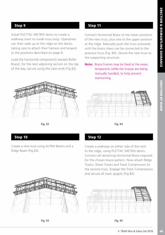
Install PLETTAC METRIX decks to create a
walkway (next to inside truss only). Operatives
can then walk up to the ridge on the decks,
taking care to attach their harness and lanyard
to the positions described on page 8.
Load the horizontal components (except Roller
Brace), for the next adjoining section on the top
of the bay, secure using the claw ends (Fig 82).
Connect Horizontal Brace to the lower positions
of the new truss, plus one to the upper position
at the ridge. Manually push the truss outwards
until the brace claws can be connected to the
previous truss (Fig. 84). Secure the new truss to
the supporting structure.
Note: Brace Frames may be fixed at the eaves
temporarily while the trusses are being
manually handled, to help prevent
overturning.
Create a walkway on either side of the roof,
to the ridge, using PLETTAC METRIX decks.
Connect all remaining Horizontal Brace required
for the chosen brace pattern. Now attach Ridge
Tracks, Sheet Tracks and Track Compressors to
the second truss. Engage the Track Compressors
and secure all track spigots (Fig 85).
Create a new truss using ALTRIX Beams and a
Ridge Beam (Fig 83).
Fig. 85
Step 9 Step 11
Step 12Step 10
Fig. 82 Fig. 84
46
COM
PON
ENTS
AC
CESS C
OM
PO
NEN
TS
ALTRIXTM User Guide46
EREC
TION
BY
HA
ND
EREC
TION
& D
ISM
AN
TLING
GU
IDA
NC
E
Fig. 86
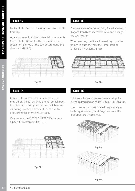
Fix the Roller Brace to the ridge and eaves of the
first bay.
Again for ease, load the horizontal components
(except Roller Brace) for the next adjoining
section on the top of the bay, secure using the
claw ends (Fig 86).
Complete the roof structure, fixing Brace Frames and
Diagonal Plan Brace at a maximum of one in every
five bays (Fig 88).
When erecting the Brace Framed bays, use the
frames to push the new truss into position,
rather than Horizontal Brace.
Pull the roof sheets over and secure using the
methods described on pages 32 & 33 (Fig. 89 & 90).
Roof sheeting can be installed sequentially as
each bay is erected, or all together once the
roof structure is complete.
Continue to erect further bays following the
method described, ensuring the Horizontal Brace
is positioned correctly. Make sure track buttons
are facing upwards on each of the trusses to
allow the fixing of the Sheet Tracks.
Only remove the PLETTAC METRIX Decks once
a bay is fully complete (Fig. 87).
Fig. 88
Fig. 89
Fig. 90
Fig. 87
Step 13 Step 15
Step 16Step 14
47
© TRAD Hire & Sales Ltd 2016 47
Fig. 91
BA
SIC
DIS
MA
NTLIN
G G
UID
AN
CE
EREC
TION
& D
ISM
AN
TLING
GU
IDA
NC
E
Prior to commencing work, always ensure risk
assessments and method statements have been
carried out. They should then be communicated
to those concerned and signed by all operatives
with records retained.
The Safe System of Work document, contained
within the site-specific risk assessment / method
statement (RAMS), should be reviewed and
amended as necessary for the dismantle operation.
Decide which safe lowering method will be used to
lower the components to the ground. For example,
hand to hand, crane, hoist, forklift truck or hand-
line, as per NASC Safety Guidance SG9.
Under no circumstances should ‘bombing’
be used to lower equipment.
Once components are safely on the ground
they should be stacked neatly ready for
transportation.
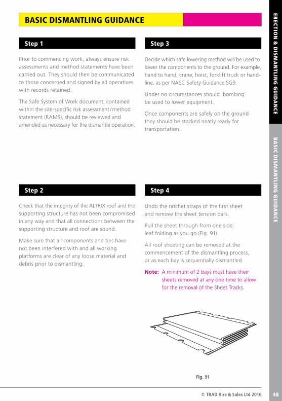
Undo the ratchet straps of the first sheet
and remove the sheet tension bars.
Pull the sheet through from one side,
leaf folding as you go (Fig. 91).
All roof sheeting can be removed at the
commencement of the dismantling process,
or as each bay is sequentially dismantled.
Note: A minimum of 2 bays must have their
sheets removed at any one time to allow
for the removal of the Sheet Tracks.
Check that the integrity of the ALTRIX roof and the
supporting structure has not been compromised
in any way and that all connections between the
supporting structure and roof are sound.
Make sure that all components and ties have
not been interfered with and all working
platforms are clear of any loose material and
debris prior to dismantling.
Step 1 Step 3
Step 4Step 2
BASIC DISMANTLING GUIDANCE
48
ALTRIXTM User Guide48
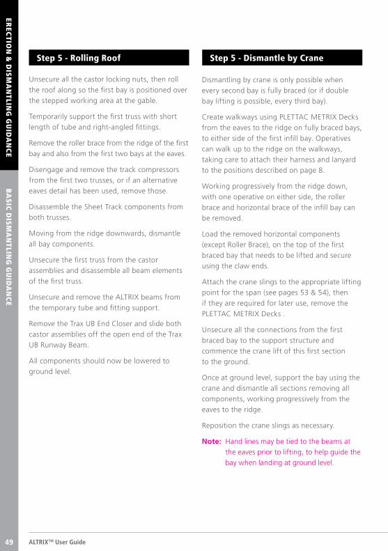
Unsecure all the castor locking nuts, then roll
the roof along so the first bay is positioned over
the stepped working area at the gable.
Temporarily support the first truss with short
length of tube and right-angled fittings.
Remove the roller brace from the ridge of the first
bay and also from the first two bays at the eaves.
Disengage and remove the track compressors
from the first two trusses, or if an alternative
eaves detail has been used, remove those.
Disassemble the Sheet Track components from
both trusses.
Moving from the ridge downwards, dismantle
all bay components.
Unsecure the first truss from the castor
assemblies and disassemble all beam elements
of the first truss.
Unsecure and remove the ALTRIX beams from
the temporary tube and fitting support.
Remove the Trax UB End Closer and slide both
castor assemblies off the open end of the Trax
UB Runway Beam.
All components should now be lowered to
ground level.
Dismantling by crane is only possible when
every second bay is fully braced (or if double
bay lifting is possible, every third bay).
Create walkways using PLETTAC METRIX Decks
from the eaves to the ridge on fully braced bays,
to either side of the first infill bay. Operatives
can walk up to the ridge on the walkways,
taking care to attach their harness and lanyard
to the positions described on page 8.
Working progressively from the ridge down,
with one operative on either side, the roller
brace and horizontal brace of the infill bay can
be removed.
Load the removed horizontal components
(except Roller Brace), on the top of the first
braced bay that needs to be lifted and secure
using the claw ends.
Attach the crane slings to the appropriate lifting
point for the span (see pages 53 & 54), then
if they are required for later use, remove the
PLETTAC METRIX Decks .
Unsecure all the connections from the first
braced bay to the support structure and
commence the crane lift of this first section
to the ground.
Once at ground level, support the bay using the
crane and dismantle all sections removing all
components, working progressively from the
eaves to the ridge.
Reposition the crane slings as necessary.
Note: Hand lines may be tied to the beams at
the eaves prior to lifting, to help guide the
bay when landing at ground level.
Step 5 - Rolling Roof Step 5 - Dismantle by Crane
BA
SIC
DIS
MA
NTLIN
G G
UID
AN
CE
EREC
TION
& D
ISM
AN
TLING
GU
IDA
NC
E
49
© TRAD Hire & Sales Ltd 2016 49
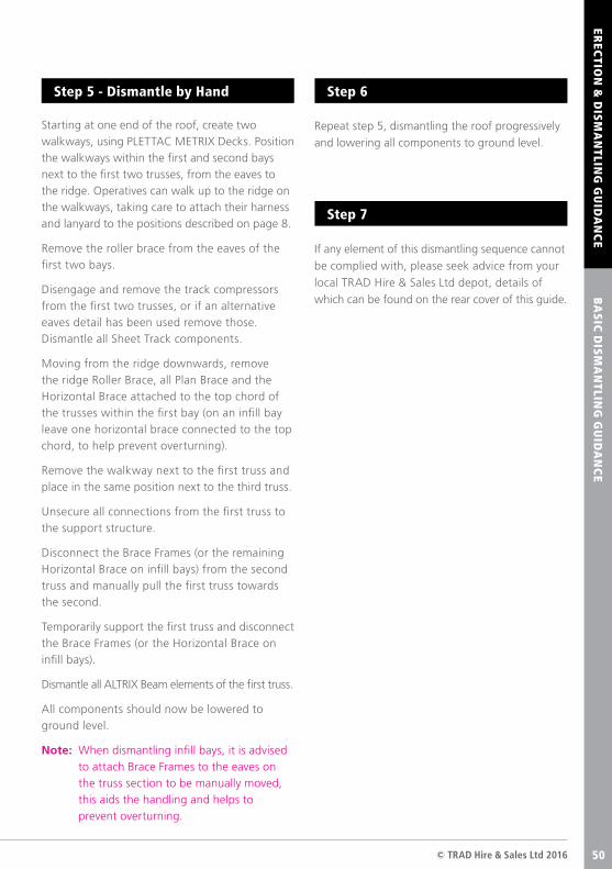
Starting at one end of the roof, create two walkways, using PLETTAC METRIX Decks. Position the walkways within the first and second bays next to the first two trusses, from the eaves to the ridge. Operatives can walk up to the ridge on the walkways, taking care to attach their harness and lanyard to the positions described on page 8.
Remove the roller brace from the eaves of the first two bays.
Disengage and remove the track compressors from the first two trusses, or if an alternative eaves detail has been used remove those. Dismantle all Sheet Track components.
Moving from the ridge downwards, remove the ridge Roller Brace, all Plan Brace and the Horizontal Brace attached to the top chord of the trusses within the first bay (on an infill bay leave one horizontal brace connected to the top chord, to help prevent overturning).
Remove the walkway next to the first truss and place in the same position next to the third truss.
Unsecure all connections from the first truss to the support structure.
Disconnect the Brace Frames (or the remaining Horizontal Brace on infill bays) from the second truss and manually pull the first truss towards the second.
Temporarily support the first truss and disconnect the Brace Frames (or the Horizontal Brace on infill bays).
Dismantle all ALTRIX Beam elements of the first truss.
All components should now be lowered to ground level.
Note: When dismantling infill bays, it is advised to attach Brace Frames to the eaves on the truss section to be manually moved, this aids the handling and helps to prevent overturning.
Repeat step 5, dismantling the roof progressively
and lowering all components to ground level.
If any element of this dismantling sequence cannot
be complied with, please seek advice from your
local TRAD Hire & Sales Ltd depot, details of
which can be found on the rear cover of this guide.
Step 5 - Dismantle by Hand Step 6
Step 7
BA
SIC
DIS
MA
NTLIN
G G
UID
AN
CE
EREC
TION
& D
ISM
AN
TLING
GU
IDA
NC
E
50
AB
OU
T TRA
D H
IRE A
ND
SALES LTD
ALTRIXTM User Guide51
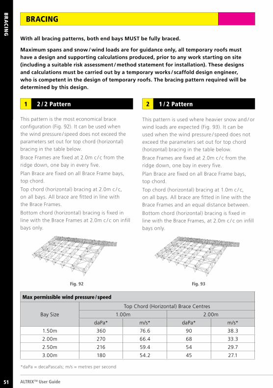
BRACING
This pattern is the most economical brace
configuration (Fig. 92). It can be used when
the wind pressure / speed does not exceed the
parameters set out for top chord (horizontal)
bracing in the table below.
Brace Frames are fixed at 2.0m c / c from the
ridge down, one bay in every five.
Plan Brace are fixed on all Brace Frame bays,
top chord.
Top chord (horizontal) bracing at 2.0m c / c,
on all bays. All brace are fitted in line with
the Brace Frames.
Bottom chord (horizontal) bracing is fixed in
line with the Brace Frames at 2.0m c / c on infill
bays only.
With all bracing patterns, both end bays MUST be fully braced.
Maximum spans and snow / wind loads are for guidance only, all temporary roofs must have a design and supporting calculations produced, prior to any work starting on site (including a suitable risk assessment / method statement for installation). These designs and calculations must be carried out by a temporary works / scaffold design engineer, who is competent in the design of temporary roofs. The bracing pattern required will be determined by this design.
2 / 2 Pattern1 1 / 2 Pattern2
This pattern is used where heavier snow and / or
wind loads are expected (Fig. 93). It can be
used when the wind pressure / speed does not
exceed the parameters set out for top chord
(horizontal) bracing in the table below.
Brace Frames are fixed at 2.0m c / c from the
ridge down, one bay in every five.
Plan Brace are fixed on all Brace Frame bays,
top chord.
Top chord (horizontal) bracing at 1.0m c / c,
on all bays. All brace are fitted in line with the
Brace Frames and an equal distance between.
Bottom chord (horizontal) bracing is fixed in
line with the Brace Frames, at 2.0m c / c on infill
bays only.
Fig. 92 Fig. 93
*daPa = decaPascals; m/s = metres per second
Max permissible wind pressure / speed
Bay Size
Top Chord (Horizontal) Brace Centres
1.00m 2.00m
daPa* m/s* daPa* m/s*
1.50m 360 76.6 90 38.3
2.00m 270 66.4 68 33.3
2.50m 216 59.4 54 29.7
3.00m 180 54.2 45 27.1
BR
AC
ING
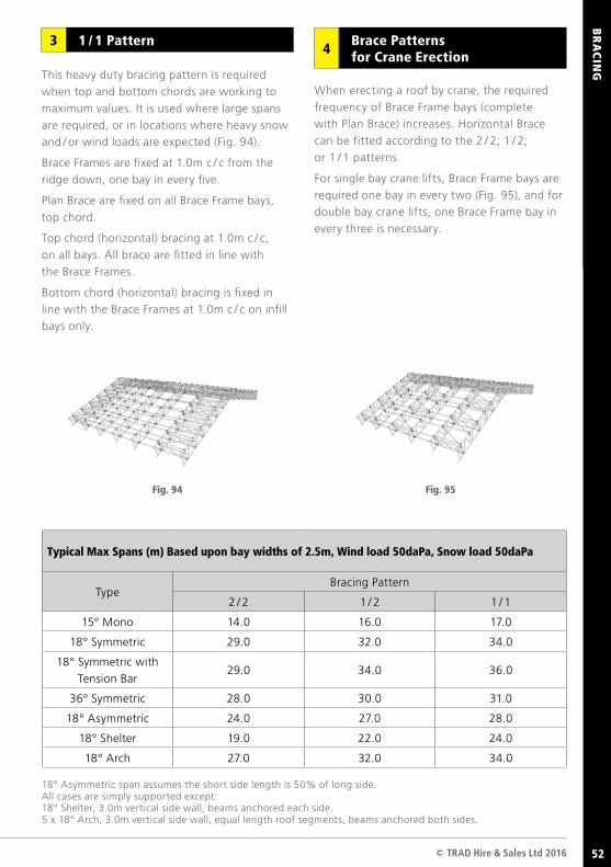
ABO
UT TR
AD
LOK
© TRAD Hire & Sales Ltd 2016 52
This heavy duty bracing pattern is required
when top and bottom chords are working to
maximum values. It is used where large spans
are required, or in locations where heavy snow
and / or wind loads are expected (Fig. 94).
Brace Frames are fixed at 1.0m c / c from the
ridge down, one bay in every five.
Plan Brace are fixed on all Brace Frame bays,
top chord.
Top chord (horizontal) bracing at 1.0m c / c,
on all bays. All brace are fitted in line with
the Brace Frames.
Bottom chord (horizontal) bracing is fixed in
line with the Brace Frames at 1.0m c / c on infill
bays only.
When erecting a roof by crane, the required
frequency of Brace Frame bays (complete
with Plan Brace) increases. Horizontal Brace
can be fitted according to the 2 / 2; 1 / 2;
or 1 / 1 patterns.
For single bay crane lifts, Brace Frame bays are
required one bay in every two (Fig. 95), and for
double bay crane lifts, one Brace Frame bay in
every three is necessary.
1 / 1 Pattern3
18° Asymmetric span assumes the short side length is 50% of long side.All cases are simply supported except:18° Shelter, 3.0m vertical side wall, beams anchored each side.5 x 18° Arch, 3.0m vertical side wall, equal length roof segments, beams anchored both sides.
Fig. 94 Fig. 95
Typical Max Spans (m) Based upon bay widths of 2.5m, Wind load 50daPa, Snow load 50daPa
TypeBracing Pattern
2 / 2 1 / 2 1 / 1
15° Mono 14.0 16.0 17.0
18° Symmetric 29.0 32.0 34.0
18° Symmetric with
Tension Bar29.0 34.0 36.0
36° Symmetric 28.0 30.0 31.0
18° Asymmetric 24.0 27.0 28.0
18° Shelter 19.0 22.0 24.0
18° Arch 27.0 32.0 34.0
Brace Patterns for Crane Erection4
BR
AC
ING
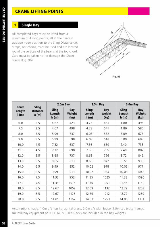
ALTRIXTM User Guide52
CR
AN
E LIFTING
PO
INTS
CRANE LIFTING POINTS
53
All completed bays must be lifted from a
minimum of 4 sling points, all at the nearest
upslope node position to the Sling Distance (x).
Straps, not chains, must be used and are located
round the verticals of the beams at the top chord.
Care must be taken not to damage the Sheet
Tracks (Fig. 96).
Single Bay1
Fig. 96
Assumptions made: 1.0m c / c top horizontal brace; 2.0m c / c plan brace; 2.0m c / c brace frames.
No infill bay equipment or PLETTAC METRIX Decks are included in the bay weights.
Beam Length
l (m)
SlingDistance
x (m)
2.0m Bay 2.5m Bay 3.0m Bay
SlingLengthh (m)
BayWeight
(kg)
SlingLengthh (m)
BayWeight
(kg)
SlingLengthh (m)
BayWeight
(kg)
6.0 2.5 4.67 423 4.73 461 4.80 495
7.0 2.5 4.67 498 4.73 541 4.80 580
8.0 3.5 5.99 537 6.03 582 6.09 623
9.0 3.5 5.99 598 6.03 648 6.09 693
10.0 4.5 7.32 637 7.36 689 7.40 735
11.0 4.5 7.32 698 7.36 755 7.40 807
12.0 5.5 8.65 737 8.68 796 8.72 849
13.0 5.5 8.65 813 8.68 877 8.72 935
14.0 6.5 9.99 852 10.02 918 10.05 977
15.0 6.5 9.99 913 10.02 984 10.05 1048
16.0 7.5 11.33 952 11.35 1025 11.38 1090
17.0 7.5 11.33 1013 11.35 1091 11.38 1161
18.0 8.5 12.67 1052 12.69 1132 12.72 1203
19.0 8.5 12.67 1128 12.69 1212 12.72 1289
20.0 9.5 14.01 1167 14.03 1253 14.05 1331
h
x
l
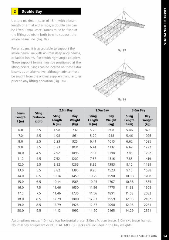
© TRAD Hire & Sales Ltd 2016 53
CR
AN
E LIFTING
PO
INTS
54
Up to a maximum span of 18m, with a beam
length of 9m at either side, a double bay can
be lifted. Extra Brace Frames must be fixed at
the lifting points in both bays to support the
inside beam line. (Fig. 97).
For all spans, it is acceptable to support the
inside beam line with 450mm deep alloy beams,
or ladder beams, fixed with right angle couplers.
These support beams must be positioned at the
lifting points. Slings can be located on these extra
beams as an alternative, although advice must
be sought from the original supplier / manufacturer
prior to any lifting operation (Fig. 98).
Double Bay2
Fig. 97
Fig. 98
Assumptions made: 1.0m c / c top horizontal brace; 2.0m c / c plan brace; 2.0m c / c brace frames.
No infill bay equipment or PLETTAC METRIX Decks are included in the bay weights.
Beam Length
l (m)
SlingDistance
x (m)
2.0m Bay 2.5m Bay 3.0m Bay
SlingLengthh (m)
BayWeight
(kg)
SlingLengthh (m)
BayWeight
(kg)
SlingLengthh (m)
BayWeight
(kg)
6.0 2.5 4.98 732 5.20 808 5.46 876
7.0 2.5 4.98 861 5.20 948 5.46 1026
8.0 3.5 6.23 925 6.41 1015 6.62 1095
9.0 3.5 6.23 1031 6.41 1132 6.62 1222
10.0 4.5 7.52 1095 7.67 1198 7.85 1292
11.0 4.5 7.52 1202 7.67 1316 7.85 1419
12.0 5.5 8.82 1266 8.95 1383 9.10 1489
13.0 5.5 8.82 1395 8.95 1523 9.10 1638
14.0 6.5 10.14 1459 10.25 1590 10.38 1708
15.0 6.5 10.14 1565 10.25 1707 10.38 1835
16.0 7.5 11.46 1630 11.56 1775 11.68 1905
17.0 7.5 11.46 1736 11.56 1891 11.68 2032
18.0 8.5 12.79 1800 12.87 1959 12.98 2102
19.0 8.5 12.79 1928 12.87 2098 12.98 2251
20.0 9.5 14.12 1992 14.20 2165 14.29 2321
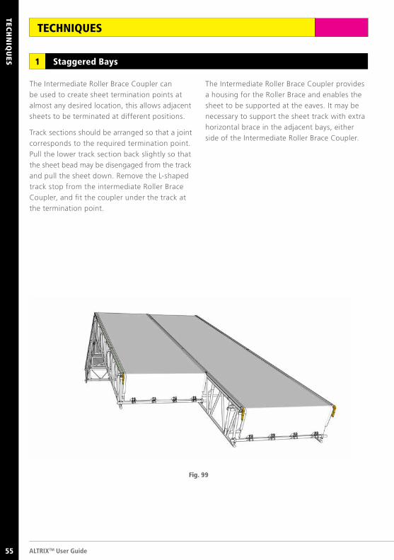
ALTRIXTM User Guide54
TECH
NIQ
UES
TECHNIQUES
Staggered Bays1
The Intermediate Roller Brace Coupler can
be used to create sheet termination points at
almost any desired location, this allows adjacent
sheets to be terminated at different positions.
Track sections should be arranged so that a joint
corresponds to the required termination point.
Pull the lower track section back slightly so that
the sheet bead may be disengaged from the track
and pull the sheet down. Remove the L-shaped
track stop from the intermediate Roller Brace
Coupler, and fit the coupler under the track at
the termination point.
Fig. 99
The Intermediate Roller Brace Coupler provides
a housing for the Roller Brace and enables the
sheet to be supported at the eaves. It may be
necessary to support the sheet track with extra
horizontal brace in the adjacent bays, either
side of the Intermediate Roller Brace Coupler.
55
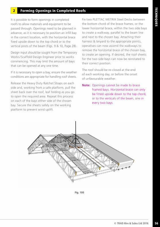
ABO
UT TR
AD
LOK
© TRAD Hire & Sales Ltd 2016 55
TECH
NIQ
UES
Forming Openings in Completed Roofs2
It is possible to form openings in completed
roofs to allow materials and equipment to be
passed through. Openings need to be planned in
advance, as it is necessary to position an infill bay
in the correct location, with the horizontal brace
fixed upside down to the top chord or to the
vertical posts of the beam (Figs. 9 & 10, Page 28).
Design input should be sought from the Temporary
Works / Scaffold Design Engineer prior to works
commencing. This may limit the amount of bays
that can be opened at any one time.
If it is necessary to open a bay, ensure the weather
conditions are appropriate for handling roof sheets.
Release the Heavy Duty Ratchet Straps on each
side and, working from a safe platform, pull the
sheet back over the roof, leaf folding as you go
to open the required area. Repeat this process
on each of the bays either side of the chosen
bay. Secure the sheets safely on the working
platform to prevent wind uplift.
Fig. 100
Fix two PLETTAC METRIX Steel Decks between
the bottom chord of the brace frames, or the
lower horizontal brace, within the two side bays
to create a walkway, parallel to the beam line
and next to the chosen bay. Attaching their
harness & lanyard to the appropriate points,
operatives can now ascend the walkways to
remove the horizontal brace of the chosen bay,
to create an opening. If desired, the roof sheets
for the two side bays can now be reinstated to
their correct position.
The roof should be re-closed at the end
of each working day, or before the onset
of unfavourable weather.
Note: Openings cannot be made to brace
framed bays. Horizontal brace can only
be fitted upside down to the top chord,
or to the verticals of the beam, one in
every two bays.
56
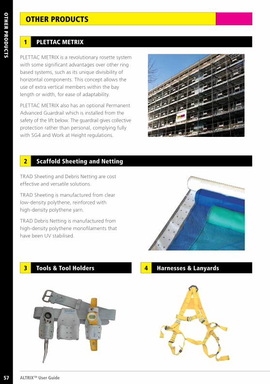
AB
OU
T TRA
D H
IRE A
ND
SALES LTD
ALTRIXTM User Guide56
OTH
ER P
RO
DU
CTS
OTHER PRODUCTS
PLETTAC METRIX is a revolutionary rosette system
with some significant advantages over other ring
based systems, such as its unique divisibility of
horizontal components. This concept allows the
use of extra vertical members within the bay
length or width, for ease of adaptability.
PLETTAC METRIX also has an optional Permanent
Advanced Guardrail which is installed from the
safety of the lift below. The guardrail gives collective
protection rather than personal, complying fully
with SG4 and Work at Height regulations.
TRAD Sheeting and Debris Netting are cost
effective and versatile solutions.
TRAD Sheeting is manufactured from clear
low-density polythene, reinforced with
high-density polythene yarn.
TRAD Debris Netting is manufactured from
high-density polythene monofilaments that
have been UV stabilised.
PLETTAC METRIX1
Scaffold Sheeting and Netting2
Tools & Tool Holders3 Harnesses & Lanyards4
57
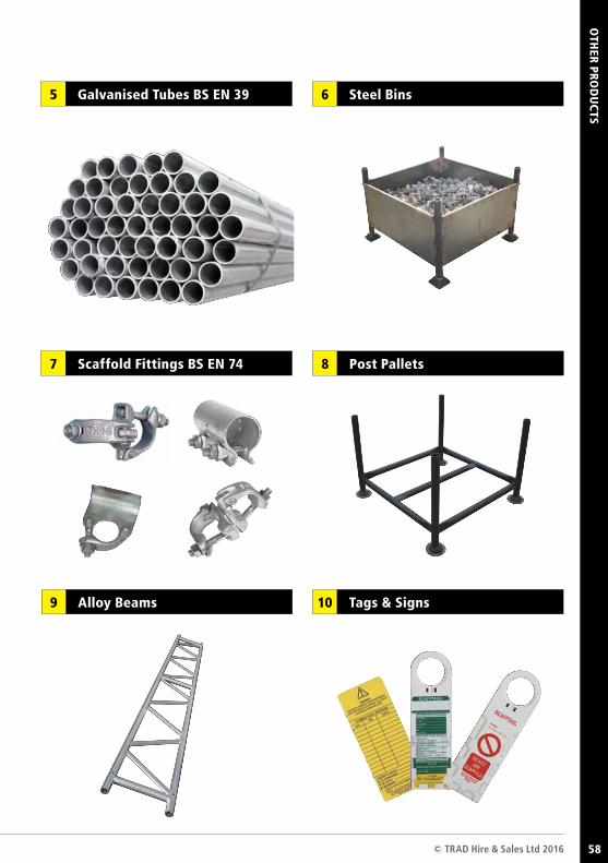
ABO
UT TR
AD
LOK
© TRAD Hire & Sales Ltd 2016 57
OTH
ER PROD
UC
TS
Steel Bins6
Post Pallets8
Tags & Signs10
Galvanised Tubes BS EN 395
Alloy Beams9
Scaffold Fittings BS EN 747
58
User guide created by Alan Slater Edition 1, May 2016
Contacts
ww
w.t
radh
irean
dsal
es.c
o.uk
Head Office TRAD Hire & Sales Ltd TRAD House Cromwell Road Bredbury Stockport SK6 2RF Tel: 0161 494 2999 Fax: 0161 494 2991
Glasgow DepotTRAD Hire & Sales LtdTRAD Wharf244 Bernard StreetGlasgow G40 3NXTel: 0141 550 3666Fax: 0141 550 3777
Leeds DepotTRAD Hire & Sales LtdTRAD House, Unit 1b 16 Cross Green Way Cross Green Industrial Estate, Leeds LS9 0SETel: 0113 249 9555Fax: 0113 249 4555
London DepotTRAD Hire & Sales LtdRenwick RoadBarkingEssex IG11 0SBTel: 020 8517 1212Fax: 020 8517 1213
Birmingham DepotTRAD Hire & Sales LtdTRAD HouseBrickhouse Lane West Bromwich West Midlands B70 0DYTel: 0121 522 2333 Fax: 0121 522 2335
Stockport DepotTRAD Hire & Sales LtdTRAD HouseCromwell RoadBredburyStockport SK6 2RFTel: 0161 430 4666Fax: 0161 430 4777
Andover Depot TRAD Hire & Sales Ltd58 Whittle Road West Portway Industrial Estate Andover, Hampshire SP10 3FB Tel: 01264 350 505 Fax: 01264 350 515
FS 614991 FS 614991