Embed Size (px)
Citation preview
i
Terminal Oxidation of n-Octane over ZSM-5 and Silicalite
Catalysts in the Liquid Phase
By
Siyabonga S. Ndlela
Submitted in fulfilment of the academic requirements for the Masters degree
to the School of Chemistry & Physics, University of KwaZulu-Natal,
Westville Campus, Durban,
South Africa
May 2016
As the candidate’s supervisor I have approved this dissertation for submission
Signed________________ Name___________________ Date___________________

ii
ABSTRACT
Three types of zeolites namely ion-exchanged ZSM-5 (Si/Al ratio of 47), framework substituted
ZSM-5, and silicalite were synthesized. The synthesis of zeolite ZSM-5 was conducted using
sol-gel method and modified using ionic exchange method to yield Fe-ZSM-5(47,IE), V-ZSM-
5(47,IE), Cr-ZSM-5(47,IE) and Mn-ZSM-5(47,IE). In addition, 1.1Fe0.8V-ZSM-5(IE) and
0.4Fe1.2V-ZSM-5(IE) catalysts were synthesized to evaluate the activity of a bimetallic catalyst.
Furthermore, the synthesis of Fe-ZSM-5(62), 1.6Fe-silicalite, 1.8V-silicalite, 0.9Fe0.8V-silicalite
and 0.3Fe1.3V-silicalite was carried out by an isomorphic substitution. The numbers represent
the metal Wt%, while the number in bracket represents Si/metal ratios. Powder XRD results
showed that only the ZSM-5 phase was obtained for all the prepared catalysts and the optical
density ratio of all the catalysts was above 0.7 confirming the catalysts’ crystalline nature. All
synthesized catalysts were tested in the oxidation of n-octane with H2O2 as the oxidant in MeCN
at 80 °C for 8 hours. Fe-ZSM-5(47,IE), V-ZSM-5(47,IE), Cr-ZSM-5(47,IE), Mn-ZSM-5(47,IE),
1.1Fe0.8V-ZSM-5(IE) and 0.4Fe1.2V-ZSM-5(IE) produced selectivities of 38, 12, 10, 6, 21 and
17 % respectively to terminal products. Furthermore, 1.6Fe-silicalite, 1.8V-silicalite, 0.9Fe0.8V-
silicalite and 0.3Fe1.3V-silicalite achieved terminal selectivities of 17, 12, 16 and 22 %
respectively while Fe-ZSM-5(62) showed 20 % terminal selectivity. The terminal selectivities
were found to increase with the decrease in the amount of vanadium used in ZSM-5 while the
opposite was true for silicalite catalysts.

iii
PREFACE
All the experimental work described in this thesis was performed at University of KwaZulu-
Natal in the School of Chemistry & Physics, Westville Campus, Durban. The experimental work
was done from May 2014 to November 2015 under the supervision of Prof. H. B. Friedrich and
mentorship of Dr. M. N. Cele.
The work presented in this thesis represents original work by the author that has not been done or
published elsewhere by others. The work of others that has been used in this work is fully
acknowledged.
_________________
Siyabonga S. Ndlela
HON (UKZN)

iv
ACKNOWLEDGEMENTS
First on the line after God the almighty, I would like to thank my mother, my grandmother and
all my siblings, their prayers and comfort kept me going all the way, even though half the time
they never understood what is it, that I was busy doing in my life. I thank God for them.
Secondly, I would also like to thank my supervisor Prof. H. B. Friedrich and my mentor Dr.
M.N. Cele for their constant and precise guidance and support. I would like to thank C* Change
for funding my studies.
Furthermore, I would like to thank the following: Catalysis Research Group for their support, the
Westville campus school of Chemistry and Physics staff for playing their part in my well-being
and my successful stay at University of KwaZulu-Natal. Also big thanks go to the EM unit at
University of KwaZulu-Natal (Westville Campus) for SEM and TEM analysis.
Lastly I would like to mention the names of the colleagues/ friends that have made the period of
my study a wonderful and challenging period by prompting insightful ideas, may God protect
and keep them. Those people are Siphokazi Zondi, Ayanda Magwenyane, Nomathamsanqa
Mkhize, Philani Mpungose, Neo Sehloko and Ayanda Mdunge.
v
COLLEGE OF AGRICULUTRE, ENGINEERING AND SCIENCE
DECLARATION - PLAGIARISM
I, ___________________________________________ declare that
1. The research reported in this thesis, except where otherwise indicated is my original
research.
2. This thesis has not been submitted for any degree or examination at any other
university.
3. This thesis does not contain other persons’ data, pictures, graphs or other information,
unless specifically acknowledged as being sourced from other person.
4. This thesis does not contain other persons’ writing, unless specifically acknowledged
as being sourced from other researchers. Where other written sources have been
quoted, then:
a. Their words have been re-written but the general information attributed to
them has been referenced.
b. Where their exact words have been used, then their writing has been placed in
italics and inside quotation marks, and referenced.
5. This thesis does not contain text, graphics or tables copied and pasted from the
Internet, unless specifically acknowledged, and the source being detailed in the thesis
and in the References sections.
Signed: _________________________
vi
CONFERENCE CONTRIBUTIONS
The following conferences have been attended where part of this work was presented:
CATSA Conference 2014, Pretoria, presented a poster entitled “Oxidative activation of n-octane
over V-ZSM-5 catalyst promoted with Fe, Cr, Mn, Co, or Ni”
CATSA Conference 2015, Western Cape, presented a poster entitled “
Catalytic oxidation of n-octane over zeolite catalysts: Investigation of active metal,
bimetallic catalysts, as well as the effects of different synthesis methods”
College of Agriculture, Engineering and Science Conference 2015, Pietermaritzburg (UKZN),
presented a poster entitled “Oxidative activation of n-octane over ZSM-5 catalysts:
Investigation of an active metal and bimetallic catalyst”
vii
ABBREVIATIONS
ATR = Attenuated Total Reflectance
BET = Brunauer-Emmet-Teller (surface area measurement technique)
CVD = Chemical Vapor Deposition
EDS = Energy Dispersive Spectroscopy
Evac = Evacuation
FT-IR = Fourier Tranform-Infrared
g = Gram
GC = Gas Chromatography
ICP-OES = Inductively Coupled Plasma-Optical Emission Spectroscopy
L = Litre
M = Molar (mole/litre)
MFI = Mordenite Framework Inverted
mg = Milligrams
Min = Minutes
mL = Millilitre
mm = Millimeter
SEM = Scanning Electron Microscopy
TEM = Transmission Electron Microscopy
Ti-MCM-41 = Titanium Mobil Composition of Matter 41
Ti-MMM-1 = Titanium Microporous Mesoporous Material 1
XRD = X-Ray Diffraction
ZSM-5 = Zeolite Socony Mobil number 5

viii
LIST OF FIGURES
Figure 1.1: A Simple Catalytic Cycle 2
Figure 1.2: A concise scheme of the Ziegler process 5
Figure 1.3: Example of reactions of the terminal hydroxyl group of an alcohol 6
Figure 1.4: Zeolite structure, pore size and molecular diameter of hydrocarbons 9
Figure 1.5: Examples of how zeolite pores affects the selectivity of reactions 11
Figure 1.6: Aim of this thesis 16
Figure 3.1: Infrared spectra of the Fresh zeolite ZSM-5 and the ZSM-5 catalysts
prepared by ion exchange 32
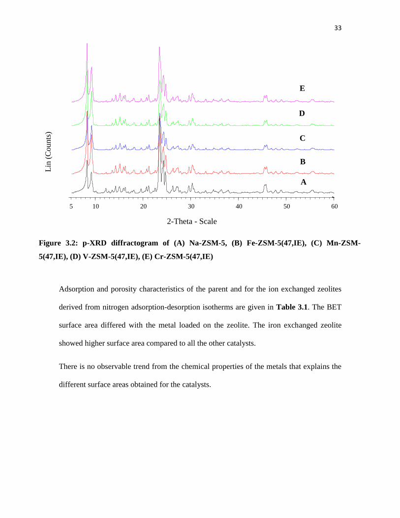
Figure 3.2: p-XRD diffractogram of (A) Na-ZSM-5, (B) Fe-ZSM-5(47,IE),
(C) Mn-ZSM-5(47,IE), (D) V-ZSM-5(47,IE), (E) Cr-ZSM-5(47,IE) 33
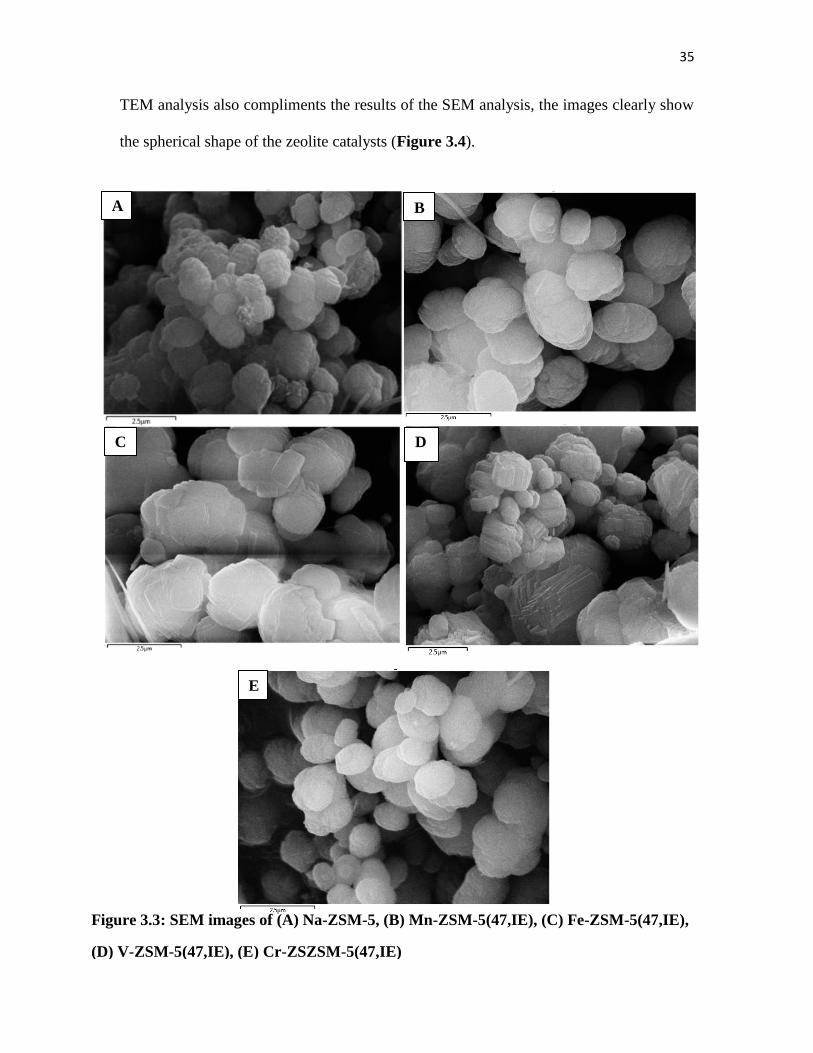
Figure 3.3: SEM images of (A) Na-ZSM-5, (B) Mn-ZSM-5(47,IE),
(C) Fe-ZSM-5(47,IE), (D) V-ZSM-5(47,IE), (E) Cr-ZSZSM-5(47,IE) 35
Figure 3.4: TEM images of (A) Na-ZSM-5, (B) Fe-ZSM-5(47, IE),
(C) V-ZSM-5(47, IE), (D) Mn-ZSM-5(47, IE), (E) Cr-ZSZSM-5(47, IE) 36
Figure 3.5: oxidation of n-octane to C8 oxygenates as the function of oxidant
and reaction time for Fe-ZSM-5(47, IE) 38
Figure 3.6: Terminal selectivity of n-octane oxidation as the function of time
using different amounts of oxidant for Fe-ZSM-5(47, IE) 39
Figure 3.7: oxidation of n-octane to C8 oxygenates as the function of
reaction time for Fe-ZSM-5(47, IE) 40
Figure 3.8: Catalytic results of n-octane oxidation over different ZSM-5 catalysts 41
Figure 3.9: Product distribution of n-octane oxidation over different ZSM-5 catalysts 42
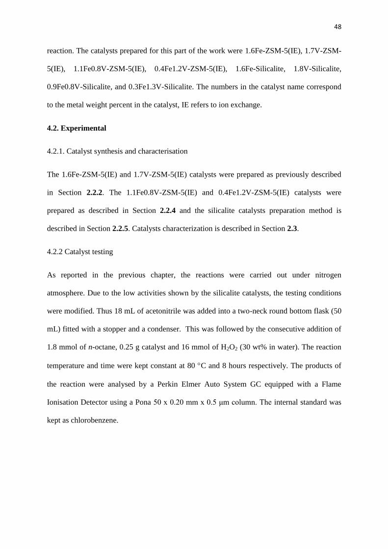
Figure 4.1: Infrared spectra of the mono/bimetallic ZSM-5 catalysts
prepared by ion exchange 49
Figure 4.2: Infrared spectra of the mono/bimetallic silicalite catalysts
prepared by ion exchange 50

ix
Figure 4.3: p-XRD diffractogram of (A) 1.6Fe-ZSM-5(IE), (B)
1.1Fe0.8V-ZSM-5(IE), (C) 0.4Fe1.2V-ZSM-5(IE), (D) 1.7V-ZSM-5(IE) 51
Figure 4.4: p-XRD diffractogram of (A) 1.6Fe-Silicalite, (B) 0.9Fe0.8V-Silicalite,
(C) 0.3Fe1.3V-Silicalite, (D) 1.8V-Silicalite 52
Figure 4.5: SEM images of (A) 1.6Fe-ZSM-5(IE), (B) 1.1Fe0.8V-ZSM-5(IE),
(C) 0.4Fe1.2V-ZSM-5(IE), (D) 1.7V-ZSM-5(IE), (E) 1.6Fe-Silicalite,
(F) 0.9Fe0.8V-Silicalite, (G) 0.3Fe1.3V-Silicalite, (H) 1.8V-Silicalite 55
Figure 4.6: TEM images of (A) 1.6Fe-ZSM-5(IE), (B) 1.1Fe0.8V-ZSM-5(IE),
(C) 0.4Fe1.2V-ZSM-5(IE), (D) 1.7V-ZSM-5(IE), (E) 1.6Fe-Silicalite,
(F) 0.9Fe0.8V-Silicalite, (G) 0.3Fe1.3V-Silicalite, (H) 1.8V-Silicalite 56
Figure 4.7: Catalytic results of n-octane oxidation over different ZSM-5 catalysts 57
Figure 4.8: Selectivity to C-1 product over different ZSM-5 catalysts at
iso-conversion of 2.7 % 59
Figure 4.9: Catalytic results of n-octane oxidation over different silicalite catalysts 60
Figure 4.10: Selectivity to C-1 products over different silicalite catalysts at
iso-conversion of 1.7 % 61
Figure 4.11: Conversion data after three reaction cycles using recycled
0.9Fe0.8V-silicalite under optimum conditions 62
Figure 5.1: Infrared spectra of the Fe-silicalite(62) and Fe-ZSM-5(62) catalysts
prepared by isomorphic substitution 71
Figure 5.2: p-XRD of the Fe-silicalite(62) and Fe-ZSM-5(62) catalysts prepared
by isomorphic substitution 71
Figure 5.3: (A) SEM image of Fe-ZSM-5(62), (B) SEM image of Fe-silicalite(62),
(C) TEM image of Fe-ZSM-5(62), and (D) TEM image of Fe-silicalite(62) 72
Figure 5.4: Catalytic results of n-octane oxidation over different catalysts systems) 73
Figure 5.5: Selectivity to C-1 product over different catalyst systems catalysts
at iso-conversion of 1.7 % 75
Figure 5.6: Conversion data after three reaction cycles using recycled catalysts
at optimum conditions 76
x
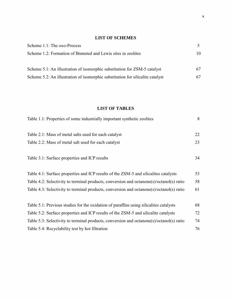
LIST OF SCHEMES
Scheme 1.1: The oxo-Process 5
Scheme 1.2: Formation of Brønsted and Lewis sites in zeolites 10
Scheme 5.1: An illustration of isomorphic substitution for ZSM-5 catalyst 67
Scheme 5.2: An illustration of isomorphic substitution for silicalite catalyst 67
LIST OF TABLES
Table 1.1: Properties of some industrially important synthetic zeolites 8
Table 2.1: Mass of metal salts used for each catalyst 22
Table 2.2: Mass of metal salt used for each catalyst 23
Table 3.1: Surface properties and ICP results 34
Table 4.1: Surface properties and ICP results of the ZSM-5 and silicalites catalysts 53
Table 4.2: Selectivity to terminal products, conversion and octanone(s)/octanol(s) ratio 58
Table 4.3: Selectivity to terminal products, conversion and octanone(s)/octanol(s) ratio 61
Table 5.1: Previous studies for the oxidation of paraffins using silicalites catalysts 68
Table 5.2: Surface properties and ICP results of the ZSM-5 and silicalite catalysts 72
Table 5.3: Selectivity to terminal products, conversion and octanone(s)/octanol(s) ratio 74
Table 5.4: Recyclability test by hot filtration 76
xi
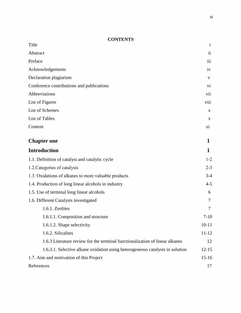
CONTENTS
Title i
Abstract ii
Preface iii
Acknowledgements iv
Declaration plagiarism v
Conference contributions and publications vi
Abbreviations vii
List of Figures viii
List of Schemes x
List of Tables x
Content xi
Chapter one 1
Introduction 1
1.1. Definition of catalyst and catalytic cycle 1-2
1.2.Categories of catalysis 2-3
1.3. Oxidations of alkanes to more valuable products 3-4
1.4. Production of long linear alcohols in industry 4-5
1.5. Use of terminal long linear alcohols 6
1.6. Different Catalysts investigated 7
1.6.1. Zeolites 7
1.6.1.1. Composition and structure 7-10
1.6.1.2. Shape selectivity 10-11
1.6.2. Silicalites 11-12
1.6.3 Literature review for the terminal functionalization of linear alkanes 12
1.6.3.1. Selective alkane oxidation using heterogeneous catalysts in solution 12-15
1.7. Aim and motivation of this Project 15-16
References 17
xii
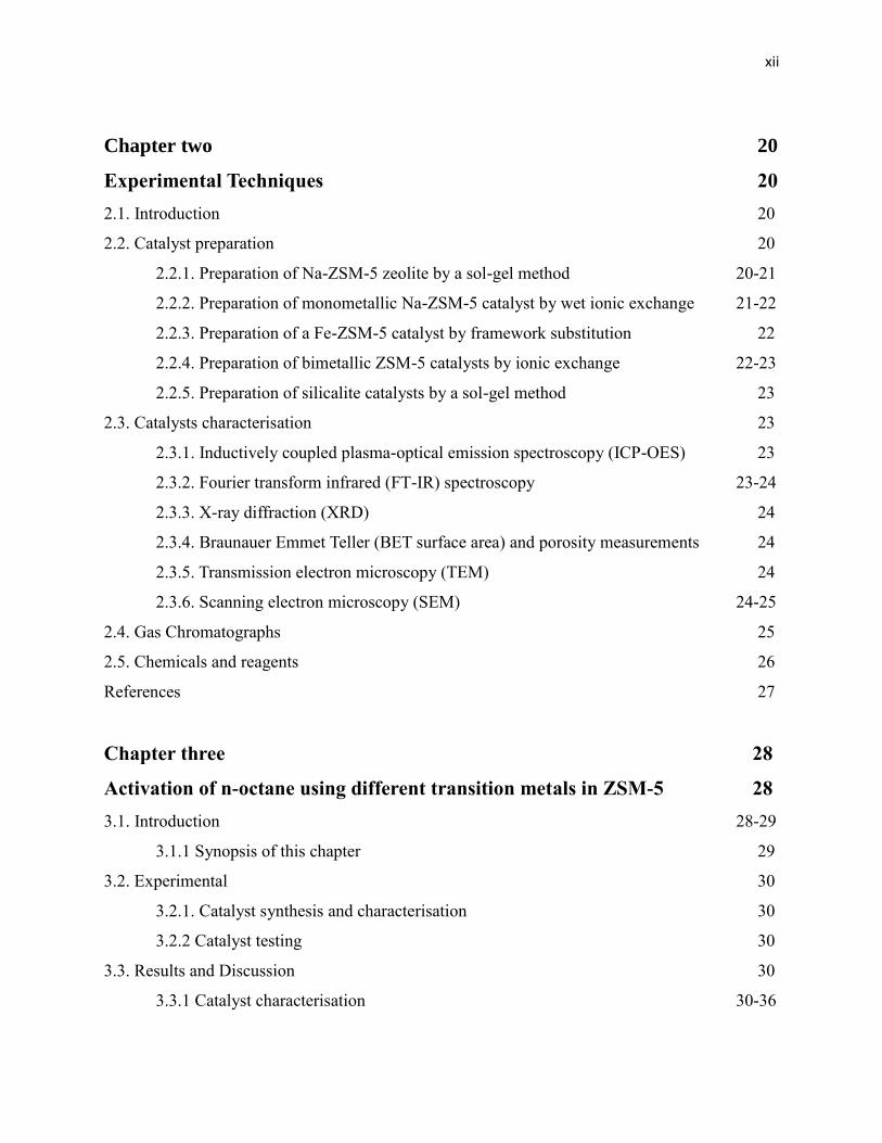
Chapter two 20
Experimental Techniques 20
2.1. Introduction 20
2.2. Catalyst preparation 20
2.2.1. Preparation of Na-ZSM-5 zeolite by a sol-gel method 20-21
2.2.2. Preparation of monometallic Na-ZSM-5 catalyst by wet ionic exchange 21-22
2.2.3. Preparation of a Fe-ZSM-5 catalyst by framework substitution 22
2.2.4. Preparation of bimetallic ZSM-5 catalysts by ionic exchange 22-23
2.2.5. Preparation of silicalite catalysts by a sol-gel method 23
2.3. Catalysts characterisation 23
2.3.1. Inductively coupled plasma-optical emission spectroscopy (ICP-OES) 23
2.3.2. Fourier transform infrared (FT-IR) spectroscopy 23-24
2.3.3. X-ray diffraction (XRD) 24
2.3.4. Braunauer Emmet Teller (BET surface area) and porosity measurements 24
2.3.5. Transmission electron microscopy (TEM) 24
2.3.6. Scanning electron microscopy (SEM) 24-25
2.4. Gas Chromatographs 25
2.5. Chemicals and reagents 26
References 27
Chapter three 28
Activation of n-octane using different transition metals in ZSM-5 28
3.1. Introduction 28-29
3.1.1 Synopsis of this chapter 29
3.2. Experimental 30
3.2.1. Catalyst synthesis and characterisation 30
3.2.2 Catalyst testing 30
3.3. Results and Discussion 30
3.3.1 Catalyst characterisation 30-36
xiii
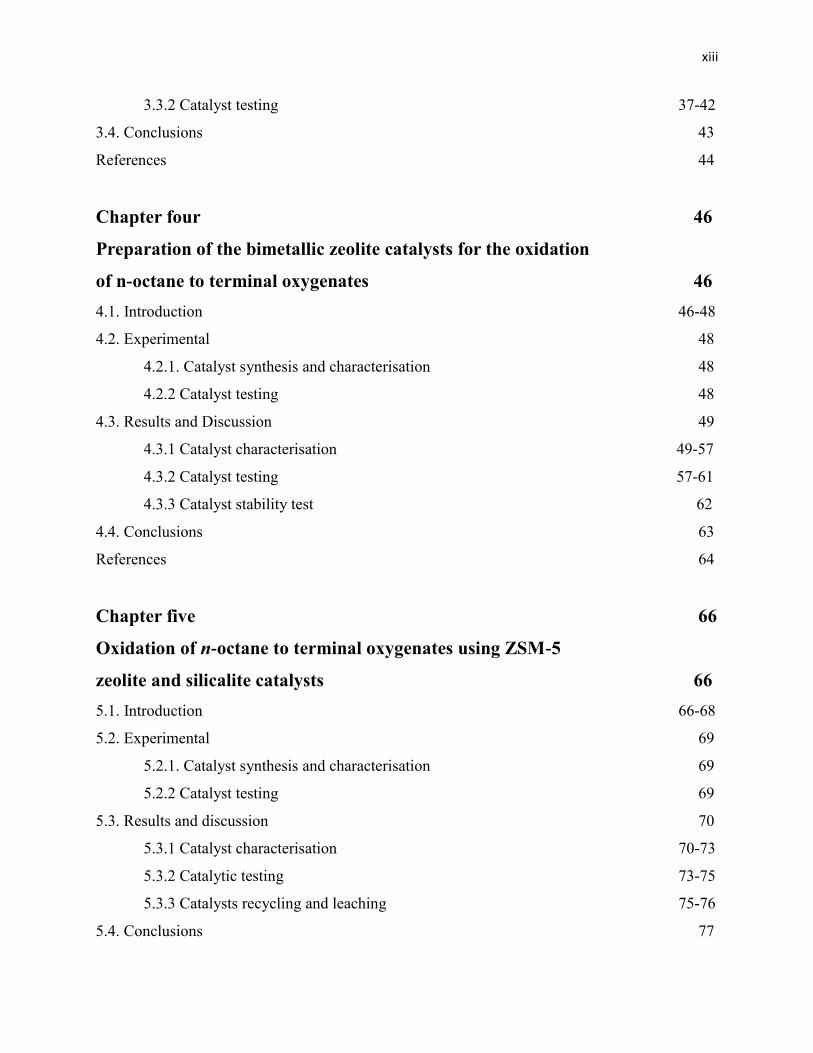
3.3.2 Catalyst testing 37-42
3.4. Conclusions 43
References 44
Chapter four 46
Preparation of the bimetallic zeolite catalysts for the oxidation
of n-octane to terminal oxygenates 46
4.1. Introduction 46-48
4.2. Experimental 48
4.2.1. Catalyst synthesis and characterisation 48
4.2.2 Catalyst testing 48
4.3. Results and Discussion 49
4.3.1 Catalyst characterisation 49-57
4.3.2 Catalyst testing 57-61
4.3.3 Catalyst stability test 62
4.4. Conclusions 63
References 64
Chapter five 66
Oxidation of n-octane to terminal oxygenates using ZSM-5
zeolite and silicalite catalysts 66
5.1. Introduction 66-68
5.2. Experimental 69
5.2.1. Catalyst synthesis and characterisation 69
5.2.2 Catalyst testing 69
5.3. Results and discussion 70
5.3.1 Catalyst characterisation 70-73
5.3.2 Catalytic testing 73-75
5.3.3 Catalysts recycling and leaching 75-76
5.4. Conclusions 77

xiv
References 78
Chapter six 79
Summary and Conclusion 79-80
Appendix 81

1
CHAPTER 1 INTRODUCTION
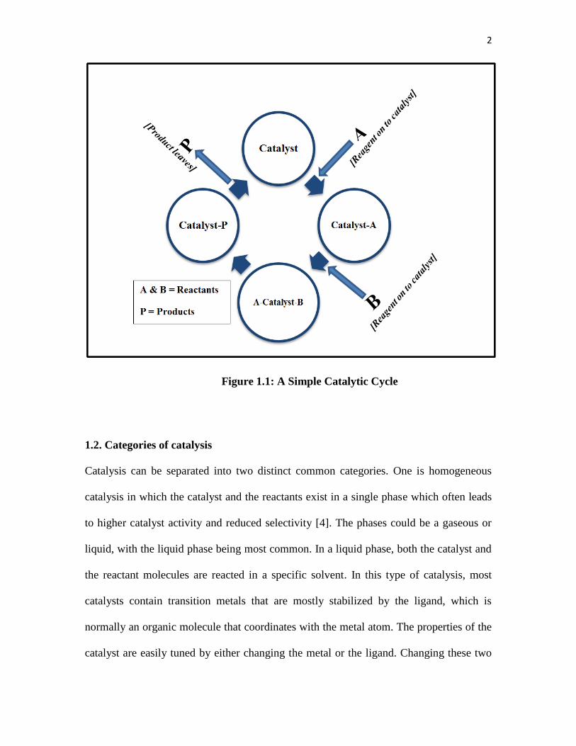
1.1. Definition of catalyst and catalytic cycle
Over the years the world has shown an enormous industrial growth that induces pressure
for chemical products. Products are now needed at shorter time intervals due to the
structure of supply chain industries. To meet the balance, substrates that can enhance the
speed of products production are developed in the industrial market. Among such
materials that are employed are catalysts.
Catalysis is one of the major important fields in chemistry and is the key approach to
sustainability [1]. Catalysis involves speeding up the rate of reaction, hence leading to
faster yields of products. Using a catalyst in a chemical reaction can also suppress some
undesirable side reactions and decrease the activation energy of the reaction, hence
increasing the thermodynamically favoured route. It is believed that the catalyst goes
through a series of uninterrupted elementary steps during the chemical reaction (Figure
1.1). At the end of the reaction, the catalyst is reproduced as it was in the beginning of the
reaction [2]. Therefore, a catalyst can be defined as the material that takes an indirect part
in the production of products without it being consumed in any way during the reaction.
In theory, what is shown by Figure 1.1 is true, but the reality is, as the catalyst goes
through the series of catalytic reaction cycles, it loses its activity and this phenomenon is
called catalyst deactivation. One can characterise a catalyst by looking at its activity,
selectivity and stability [3].
2
1.2. Categories of catalysis
Catalysis can be separated into two distinct common categories. One is homogeneous
catalysis in which the catalyst and the reactants exist in a single phase which often leads
to higher catalyst activity and reduced selectivity [4]. The phases could be a gaseous or
liquid, with the liquid phase being most common. In a liquid phase, both the catalyst and
the reactant molecules are reacted in a specific solvent. In this type of catalysis, most
catalysts contain transition metals that are mostly stabilized by the ligand, which is
normally an organic molecule that coordinates with the metal atom. The properties of the
catalyst are easily tuned by either changing the metal or the ligand. Changing these two
Figure 1.1: A Simple Catalytic Cycle
3
components can either reduce or improve the catalyst selectivity, activity, as well as
stability. The major drawbacks in homogenous catalysis are the difficulty in product and
catalyst separation and recycle after use. This is the reason why more than 80 % of
industrial catalytic applications are carried out using heterogeneous catalysis [1, 4, 5].
In heterogeneous catalysis, the reactants and the catalyst are in different phases. These
could be solid, liquid, gas or immiscible liquids. The different phases in heterogeneous
catalysis lead to easy separation of products and also the catalyst can be used in more
than one cycle in a catalytic reaction.
Catalytic selective oxidation plays a key role in industrial chemicals and intermediates
manufacturing. Catalysis is the sector that dominates the global chemical industrial
technology, with more than 80 % of all chemical products being synthesized using
catalytic routes [8]. More than 60 % of the industrial chemical products are oxidation
products [8]. According to the National Institute of Standards and Technology, the
American chemical industry produces products worth $375 billion per year [9]. These
figures imply that catalysis is one of the most important processes in the world.
1.3. Oxidations of alkanes to more valuable products
Alkanes are saturated hydrocarbons and this means that they are stable compounds and
also they have no specific region of attack with no preferred reaction site. This limits
their applications in the chemical industry, but makes them very economical and
environmentally friendly substances. Saturated hydrocarbons often give more energy and
less carbon dioxide compared to burning of unsaturated hydrocarbons. The main sources
of alkanes are natural gas and petroleum, but a large amount is also produced from
4
carbon monoxide and hydrogen by the Fischer-Tropsch process [6]. To make alkanes
reactive species, one must cleave the C-C or the C-H bonds. Thereafter they can undergo
reactions such as dehydrogenation, substitution, oxidative dehydrogenation and chain
cleavage. Catalytically, functionalizing the terminal carbon of long linear alkanes still
remains a challenge owing to the difficulty of controlling regioselectivity, as mentioned
above. The secondary carbon-hydrogen bond dissociation energy of linear alkanes is 94.6
kcal mol-1
, while for the primary carbon it is 104 kcal mol-1
. These energies explain why
the secondary carbons react faster than the primary carbons [7]. Because the internal
positions of long linear alkanes, such as n-octane, react faster (secondary carbons are
more reactive than primary carbons), the oxidation products will be a mixture of internal
alcohols and ketones.
The spontaneous reaction of oxygen with alkanes is called autoxidation. This is another
challenge that needs to be overcome when working in the liquid phase. Autoxidation
selectivity also follows the trend set by the energy of the C-H bond dissociation.
Therefore it also favors the oxidation of the internal positions in long linear alkanes [7].
1.4. Production of long linear alcohols in industry
Industrial production of long linear alcohols is carried out using Ziegler and oxo
processes. These are both multistep processes which use alkenes as their feed. The
Ziegler processes (Figure 1.2) is a five step process and uses ethylene as the starting
material. At the end of the process, the alcohols are formed with aluminium hydroxide.
This process is not a catalytic process, since Al2O3 is not recycled to Al(Et)3 but
converted to aluminium hydroxide instead [10, 11].

5
The oxo-process (Scheme 1.1), which is a term used instead of hydroformylation, also
uses ethylene as the feed for the reaction with a H2/ CO gas mixture in the presence of the
catalyst. The reaction yields both linear and branched aldehydes [11].
2R-RH=RH2 + 2CO +2H2 R-CH2-CH2-CHO + R-CH (CH3)-CHO
Scheme 1.1: The oxo-Process
Figure 1.2: A concise scheme of the Ziegler process
HCo(CO)4

6
1.5. Use of terminal long linear alcohols
Terminal alcohols can be incorporated with other groups to give a vast variety of useful
derivatives. These could be aldehydes, ketones or carboxylic acids. Figure 1.3 shows
some industrial alcohol derivatives. These derivatives are very important in different
industries. Different properties of alcohols make them suitable for a variety of
applications. The use of alcohols as surfactants results from their amphiphilic character.
This property, to a lesser extent, allows them to be used in cosmetics as well. Alcohols
are also used as detergents because they aggregate at the interphase between two phases
to form micelles, which have properties that dissolve organic compounds in water. Other
uses are in plastic and cement compositions [11].
1.7. Catalysts used in this project.
1.7.1. Testing in Liquid phase.
Terminal linear alcohols + Oxygen Aldehyde, Carboxylic Acid
+ Alkali Melt Carboxylic Acids
+ Alkali Dimeric Alcohol
+ Proton Ether, Olefin
+ Alkyne Vinyl Ether
+ Carboxylic Acid Ester
+ Hydrogen Halide Alkyl Halides
+ Ammonia / Amine Amines
+ Aldehyde / Ketone Acetals
+ Sulfide Thiols
+ Alcoholate / H2S Xanthates
+ Metals Metal Alkoxides
+ Ethylenoxide / SO3 Ethoxilates/Ethersulfates
Figure 1.3: Example of reactions of the terminal hydroxyl group of an alcohol [11]
7
1.6. Different Catalysts investigated
1.6.1. Zeolites
1.6.1.1. Composition and structure
Zeolite discovery dates back to the middle of the eighteenth century when Baron
Cronstadt heated crystals of certain minerals and they appeared to melt and boil at the
same temperature by a phenomenon called intumescence. The name zeolite, given to the
materials that intumesce, is from the Greek “zeo” to boil and “lithos” stone [12].
The building blocks of zeolites are the pores and channels of the 3D-aluminosilicate
framework which makes up a crystalline microporous material. Zeolites find their main
industrial importance in petroleum processing. They are used as adsorbents or desiccants,
as ion-exchangers and as catalysts. The crystal structure of the zeolite is known. Zeolites
bring an advantage that they can contain well defined pores in which the catalytically
active sites are embedded [13-16]. The metal in the zeolite can be contained within the
cages of its framework, which leads to reduced leaching probability [17].
Zeolites can be synthesized or be found in nature. At present more than 600 zeolites are
known, with the conformation of SiO4 and AlO4 arranged differently to give the different
zeolites. Many zeolites are commercialized for use in industry. The properties of some
industrially important zeolites are defined in Table 1.1.

8
Table 1.1: Properties of some industrially important synthetic zeolites [13-16].
Name Structure
type
Window Dimensionality
of pore system
Pore aperture
(nm)
SiO2/Al2O3
A LTA 8-ring 3 0.41 2.0 – 6.8
P GIS
8-ring
3 0.31 x 0.45
0.28 x 0.48 2.0 – 5.0
ZSM-5 MFI
10-ring
10-ring
3
0.53 x 0.56
0.51 x 0.55 20 – ∞
X FAU 12-ring 3 0.74 2.0 – 3.0
Y FAU 12-ring 3 0.74 3.0 – 6.0
Mordenite MOR
12-ring
8-ring
2
0.65 x 0.70
0.26 x 0.57 9.0 – 35
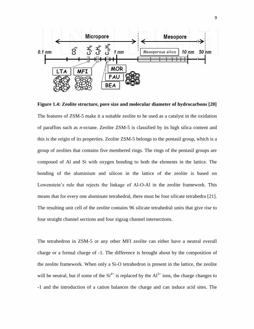
From Table 1.1, the zeolites channel windows range from eight to twelve oxygen atom
rings, the pore diameters range from 0.41 nm to about 0.74 nm, which are similar to the
diameter of the n-alkane of interest (Figure 1.4). These are the factors that lead to the
selectivity of zeolites. The silica to aluminium ratios tell more about the acidity that
enables the zeolites to be used as shape-selective catalysts in industrial applications and
also tells us about the ionic exchange capacity of the zeolite material [18].
Zeolites have been used in many applications, which include the synthesis of
ethylbenzene, the isomerisation of xylene and the disproportionation of toluene [19, 20].
9
Figure 1.4: Zeolite structure, pore size and molecular diameter of hydrocarbons [20]
The features of ZSM-5 make it a suitable zeolite to be used as a catalyst in the oxidation
of paraffins such as n-octane. Zeolite ZSM-5 is classified by its high silica content and
this is the origin of its properties. Zeolite ZSM-5 belongs to the pentasil group, which is a
group of zeolites that contains five membered rings. The rings of the pentasil groups are
composed of Al and Si with oxygen bonding to both the elements in the lattice. The
bonding of the aluminium and silicon in the lattice of the zeolite is based on
Lowenstein’s rule that rejects the linkage of Al-O-Al in the zeolite framework. This
means that for every one aluminate tetrahedral, there must be four silicate tetrahedra [21].
The resulting unit cell of the zeolite contains 96 silicate tetrahedral units that give rise to
four straight channel sections and four zigzag channel intersections.
The tetrahedron in ZSM-5 or any other MFI zeolite can either have a neutral overall
charge or a formal charge of -1. The difference is brought about by the composition of
the zeolite framework. When only a Si-O tetrahedron is present in the lattice, the zeolite
will be neutral, but if some of the Si4+
is replaced by the Al3+
ions, the charge changes to
-1 and the introduction of a cation balances the charge and can induce acid sites. The

10
negatively charged tetrahedron corresponds to a base [22]. Zeolites can have both
Brønsted acid sites and Lewis acid sites (Scheme 1.2).
Scheme 1.2: Formation of Brønsted and Lewis sites in zeolites [23]
According to Scheme 1.2, the Brønsted acid sites arise from bridging hydroxyl groups
within the pore structure of zeolites. An increase in temperature causes the protons to
move and at 600 °C under evacuation they can be lost as water molecules which results
in the formation of Lewis acid sites. This can be reversed at room temperature to obtain
Brønsted acid sites [23].
The Si/Al ratio controls the hydrophilicity of the zeolites, in which ZSM-5 tends to be
moderately hydrophilic to highly hydrophobic. Other zeolites with low silica content,
such as types A, X, and Y, are very hydrophilic [24]. The high stability of zeolites to
thermal treatment and acidity makes it possible for them to be tuned without any
structural defects.
1.6.1.2. Shape selectivity
Zeolites have a narrow range of pore sizes because of their crystallinity, which results in
better selectivity than non-crystalline or amorphous materials. From Figure 1.5, reactant
selectivity is the phenomenon whereby the zeolite discriminates the reactants in terms of
their size. The bulky molecules are excluded from entering the intra-crystalline channel-
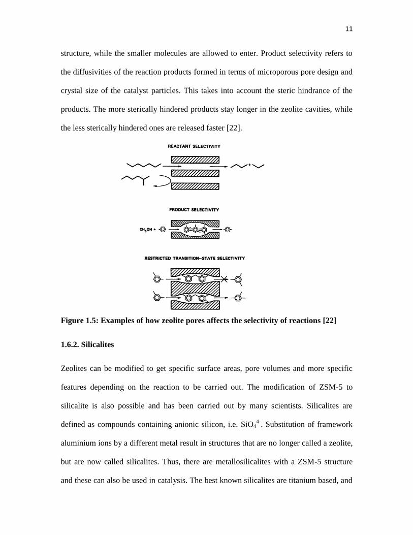
11
structure, while the smaller molecules are allowed to enter. Product selectivity refers to
the diffusivities of the reaction products formed in terms of microporous pore design and
crystal size of the catalyst particles. This takes into account the steric hindrance of the
products. The more sterically hindered products stay longer in the zeolite cavities, while
the less sterically hindered ones are released faster [22].
Figure 1.5: Examples of how zeolite pores affects the selectivity of reactions [22]
1.6.2. Silicalites
Zeolites can be modified to get specific surface areas, pore volumes and more specific
features depending on the reaction to be carried out. The modification of ZSM-5 to
silicalite is also possible and has been carried out by many scientists. Silicalites are
defined as compounds containing anionic silicon, i.e. SiO44-
. Substitution of framework
aluminium ions by a different metal result in structures that are no longer called a zeolite,
but are now called silicalites. Thus, there are metallosilicalites with a ZSM-5 structure
and these can also be used in catalysis. The best known silicalites are titanium based, and

12
they are named TS-1. This silicalite has been used and studied more than any other
silicalites [25, 26].
1.6.3 Literature review for the terminal functionalization of linear alkanes
Functionalising the terminal carbon of saturated hydrocarbons remains one of the
interesting and challenging topics in the chemical industry. This is even more difficult to
carry out with alkanes with long chains (hence much research is done on lower alkanes),
and this is because of the regioselectivity issues associated with these substances.
1.6.3.1. Selective alkane oxidation using heterogeneous catalysts in solution
Alkane oxidation has been explored using three broad and commonly known types of
catalysis, i.e. homogeneous, heterogeneous and bio-catalysis. The work contained in this
thesis is based on the heterogeneous part of catalysis; therefore most of the literature
review focuses on this. This is because the chemical industry sees more advantages in
heterogeneous catalysts. Hence, as mentioned before in Section 1.2, more that 80 % of
industrial applications are carried out via heterogeneous catalysis. However, bio-catalysis
is a promising part of catalysis now. Biocatalysts have properties that make them highly
selective catalysts under mild reaction conditions and can also offer ease of separation
[27, 28]. Some of the broadly used and known biocatalysts are methane monooxygenase,
alkane hydroxylase and cytochrome P450. These are very good catalysts for the
activation of alkanes to their corresponding alcohols. The major drawback with these
enzyme/whole cell based catalysts is that they have very limited regions of operation
[27].
13
Homogeneous catalysis is known for its ability to give high conversions. A disadvantage
is the difficulty in the product separation at the end of the reaction and also the product
contamination with catalyst is greatest in homogeneous catalysis [4]. What follows is a
review on the oxidation of n-octane by heterogeneous catalysts.
Singh and Selvam reported on n-octane oxidation using chromium and vanadium silicate-
1 (CrS-1 and VS-1 respectively) with tert-butyl hydroperoxide as an oxidant. In this
work, conversions of 7.7 and 8.7 % and terminal selectivities of 1.0 and 0.2 % for the two
catalysts respectively were reported. The major drawback of these catalysts is the poor
terminal selectivity [29].
In other work carried out [30], no terminal selectivity was reported using Ti-MMM-1,
TS-1 and Ti-MCM-41 as catalysts and hydrogen peroxide as the oxidant. This work
reported conversions as high as 19.8 % and selectivities up to 80 % to the 2-, 3-, and 4-
alcohols. While alcohols are important in industry, terminal oxidation gives even more
useful alcohols and therefore it is better to have a catalyst system that is capable of
achieving that.
Other work on n-octane oxidation reported conversions of 2.9 and 1.8 % and total
terminal selectivities of 8.8 and 13 % using Fe-NaY and FeTPP-NaY respectively [31].
This work was done in a liquid phase system using hydrogen peroxide as the oxidant.
Setbacks of this system are relatively poor terminal product selectivities and relatively
low conversions.
14
In another recent study, the oxidation of n-octane was carried out using three catalysts
based on Fe-MOF-5. These catalysts were named Fe4-MOF-5, Fe2–Zn2-MOF-5 and
Fe0.9–Zn3.1-MOF-5. The results showed that the terminal selectivity increased with a
decrease in Fe content and increase in the Zn content of the catalysts. The conversions
showed the opposite trend [32]. The highest terminal selectivity obtained was 19.8 %.
In the previous summarized reports [29-32], the oxidation of n-octane gave the
corresponding C-8 oxygenated products, such as octanol, octanones, octanal and no
octanoic acid, which is the kind of systems that the work contained in this thesis is based
on. The scope of n-octane oxidation is much larger than this, because in other studies (gas
phase) the oxidation of n-octane gave a mixture of products including octenes, aromatics,
cracked products, COx and short chain oxygenates. In one system, vanadium based
catalysts were used at higher temperatures and a conversion of 16 % was achieved with
selectivity of 51 % towards heptenes, 14 % aromatics and 15 % oxygenates for a total
value added products selectivity of 80 % [33].
In another similar study as the above, a similar product distribution was reported with
much improved selectivity to oxygenated products. The catalysts in this study were based
on cerium. The selectivity to terminal oxidation was poor, as it was below 5 % at a
conversion of around 30 % [34].
One study that was carried out using a similar system of catalyst as the one used in this
study was on the activation of hexane over vanadium modified zeolite ZSM-5. The Na-

15
V-ZSM-5 catalyst for this study was prepared via solid state ion-exchange with one
weight percent metal loading. This was a gas phase study which activated hexane to a
range spectrum of products such as alcohols, ketones, alkenes and aromatic compounds.
The conversions obtained in this study were very high with poor terminal selectivity. The
highest conversion obtained was 39 % with selectivities to 1-hexanol and hexanoic acid
of 1.6 and 2.1 % respectively [35]. High temperature, poor terminal selectivity and COx
formation were the major drawbacks of the study, because this can reduce the life time of
the catalyst.
The reaction between alkanes and oxygen species proceeds via different pathways, and
there is competition between parallel and consecutive reactions [7]. The literature
explored shows that a variety of products can form from one reaction and, therefore,
product selectivity in this branch of catalysis still remains the challenge. The goal
remains to develop a catalyst system that is selective to the desired product at decent
conversion.
1.7. Aim and motivation of this Project
Medium to long linear alkanes have multiple reaction sites; hence the functionalization of
the terminal carbon remains a major challenge because it is very difficult to control
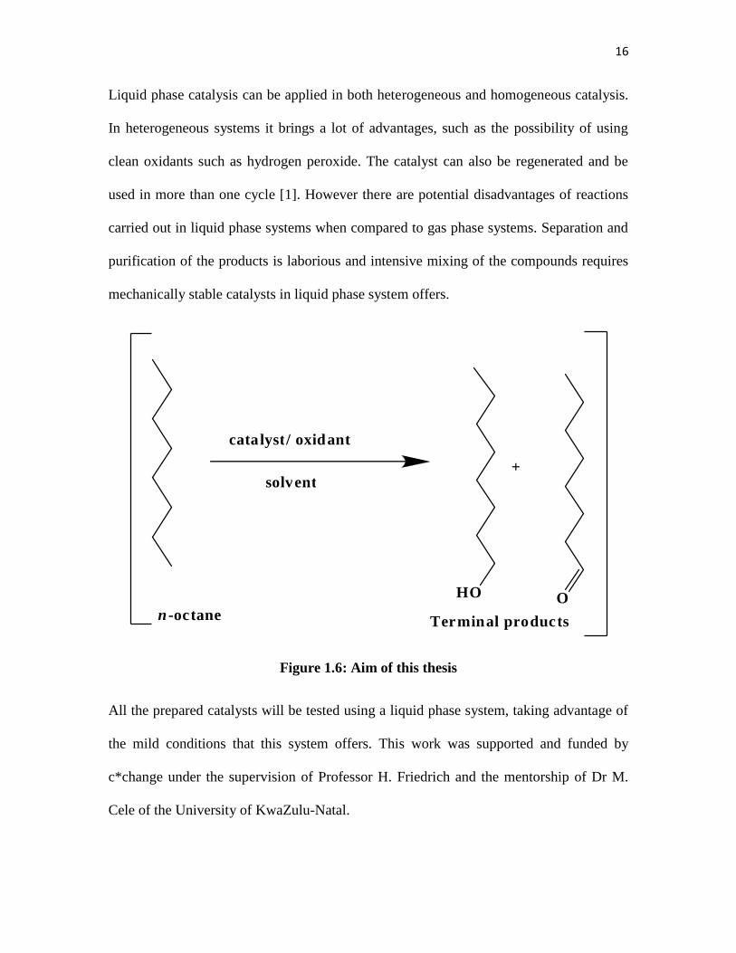
regioselectivity. Therefore, the aim of this project is to investigate liquid phase medium
linear n-alkane terminal activation using the selective oxidation of n-octane (as the model
n-alkane) to 1-octanol and octanal over ZSM-5 and silicalite zeolite catalysts in
acetonitrile as a solvent and H2O2 as the oxidant (Figure 1.6).
16
Liquid phase catalysis can be applied in both heterogeneous and homogeneous catalysis.
In heterogeneous systems it brings a lot of advantages, such as the possibility of using
clean oxidants such as hydrogen peroxide. The catalyst can also be regenerated and be
used in more than one cycle [1]. However there are potential disadvantages of reactions
carried out in liquid phase systems when compared to gas phase systems. Separation and
purification of the products is laborious and intensive mixing of the compounds requires
mechanically stable catalysts in liquid phase system offers.
Figure 1.6: Aim of this thesis
All the prepared catalysts will be tested using a liquid phase system, taking advantage of
the mild conditions that this system offers. This work was supported and funded by
c*change under the supervision of Professor H. Friedrich and the mentorship of Dr M.
Cele of the University of KwaZulu-Natal.
c a t a l y s t / o x i d a n t
s o l v e n t +
O H O
n - o c t a n e T e r m i n a l p r o d u c t s

17
References
[1] T. Naicker, A. K. Datye, H. B. Friedrich, Appl. Catal. A, 350, 2008, 102.
[2] M. Bowker, The Basis and Application of Heterogeneous Catalysis, Oxford.
Chemistry, Primers, Oxford Science Publications, 1998.
[3] I.W.C.E. Arends, R.A. Sheldon, Appl. Catal. A., 212, 2001, 187.
[4] A. Sivaramakrishna, P Suman, E. V. Goud, S Janardan, C Sravani, C. S. Yadav, H. S.
Clayton, Res. and Rev. in Mater. Sci. and Chem., 1, Issue 1, 2012, 103.
[5] A. Sivaramakrishna, P. Suman, E. V. Goud, S. Janardan, C. Sravani, T. Sandep, K.
Vijayakrishna and H. S. Clayton, J. Coord. Chem., 66, 2013, 2109.
[6] A. Arora, Hydrocarbons (Alkanes, Alkenes And Alkynes), Discovery Publishing
House Pvt. Limited., (2006), ISBN 9788183561426. Date accessed: August 2015.
[7] J.A. Kerr, Bond Dissociation Energies by Kinetic Methods, Chem. Rev., 66, 1966,
465.
[8] http://catl.sites.acs.org/, Date accessed March 2016.
[9] http://www.atp.nist.gov/atp/97wp-cat.htm, Date accessed March 2016.
[10] K. Ziegler, H.G. Gellert, K. Zosel, E. Holzkamp, J. Schneider, M. SÖll, W.R. Kroll,
Justus Liebigs Ann. Chem. 121 ,1960, 629.
[11] K. Ziegler, All about the Fatty Alcohols, Lecture notes, Condea, 2000, 12.
[12] S. M. Auerbach, K. A. Carrado, P. K. Dutta, Handbook of Zeolite Science and
Technology, 2003, 5.
[13] I. Chorkendorff, J. W. Niemantsverdriet, Concepts of modern catalysis and kinetics,
Wiley-VCH, Weinheim, 2003. 205.
18
[14] E. Roland and P. Kleinschmit, Zeolites, Ullmann’s Encyclopaedia of Industrial
Chemistry, 7th Edition, 2005, Electronic release, 31.
[15] Kirk-Othmer Encyclopaedia of Chemical Technology, Vol 5, 245.
[16] J. Weitkamp, Solid State Ionics, 131, 2000, 175.
[17] P. A. Jacobs, W. J. Mortier, J. B. Uytterhoeven, J. Inorg. Nucl. Chem., 40, 1978,
1923.
[18] P.J. Smeets, J.S. Woertink, B.F. Sels, E.I Solomon, R.A. Schoonheydt, Inorg Chem.,
49, 2010, 3583.
[19] H. Sato, Catal. Rev. -Sci. Eng., 39, 1997, 395.
[20] T. Tago, T. Masuda, Zeolite Nanocrystals- Synthesis and Applications,
Nanocrystals, 2010, Yoshitake Masuda (Ed.), ISBN: 978-953-307-126-8, InTech,
Available from: http://www.intechopen.com/books/nanocrystals/zeolite-nanocrystals
synthesis-and-applications.
[21] M. J. Hogben, High Throughput Optical Materials, University of Southampton, PhD
thesis, 2008, 8.
[22] M. Stöcker, Micropor. Mesopor. Mat., 82, 2005, 257.
[23] J. Kondo, R. Nishitani, E. Yoda, T. Yokoi, T. Tatsumi, K. Domen, Phys. Chem.
Chem. Phys., 12, 2010, 11586.
[24] B.L. Meyers, S.H. Ely, N.A. Kutz, J.A. Kaduk, E. van den Bossche, J. Catal., 91,
1985, 352.

19
[25] M. G. Clerici, O. A. Kholdeeva, Liquid Phase Oxidation via Heterogeneous
Catalysis: Organic Synthesis and Industrial Applications, Wiley EBOOKS, 2013.
[26] G. Ricchiardi, A. Damin, S. Bordiga, C. Lamberti, G. Spano, F. Rivetti, and A.
Zecchina, J. Am. Chem. Soc. 123, 2001, 11419.
[27] T. Johannes, M. R. Simurdiak, H. Zhao, Biocatalysis, Encyclopaedia of Chemical
Processing DOI: 10.1081/E-ECHP-120017565, 2006, 109.
[28] M. Ayala, E. Torres, Appl. Catal. A., 272, 2004, 13.
[29] A.P. Singh, T. Selvam, J Mol. Catal. A-Chem., 113, 1996, 497.
[30] R. H.P.R. Poladi, C. C. Landry, Micropor. Mesopor. Mat., 52, 2002, 18.
[31] M. N. Cele, H.B. Friedrich, M. D. Bala, Reac. Kinet. Mech. Cat., 111, 2014, 750.
[32] M.N. Cele, H.B. Friedrich, M. D. Bala, Catal. Commun., 57, 2014, 102.
[33] V. D. B. C. Dasireddy, S. Singh, H. B. Friedrich, Appl. Catal. A., 456, 2013, 117.
[34] M. Narayanappa, V. D. B. C. Dasireddy, H. B. Friedrich, Appl. Catal. A., 143, 2012,
448.

20
Chapter two Experimental Techniques
2.1. Introduction
In this chapter, the details of the catalysts synthesis, the characterisation techniques used
to define the prepared catalysts, the catalytic experimental conditions used for the
reactions carried out and also the products analyses and quantification at the end of the
reaction are discussed.
2.2. Catalyst preparation
2.2.1. Preparation of Na-ZSM-5 zeolite by a sol-gel method
The zeolite used for all the catalysts syntheses was prepared using a Teflon lined Parr
reactor set up which was the hot plate and oil bath. The prepared ZSM-5 had a Si/Al ratio
of 47:1 and contained the following oxide mole compositions: SiO2 = 0.325523 mol and
Al2O3 = 0.0065105 mol.
In a Teflon beaker, 2.442 g of aluminium nitrate salt [Al(NO3)3.9H2O] was dissolved in
100 mL of deionised water, which was previously acidified by three drops of perchloric
acid. After the salt has dissolved, 3.5 mL of perchloric acid was added to the solution.
This solution was labelled solution 1.
In a second Teflon beaker, 25 g of sodium silicate [Na2O3Si] solution was added to 141
mL of deionised water. This was labelled solution 2. Both the solutions were kept in the
fridge overnight.

21
While still cold, solution 2 was added drop wise to solution 1 with vigorous stirring until
the pH was at 4.5 (using pH paper). About 14.8 mL of 40 % colloidal silica was added
into the remainder of solution 2, which was then followed by the addition of sodium
chloride (2 g) and 6.7 g tetrapropylammonium bromide [TPA] to the slurry that resulted.
This was then added to solution 1 and the resultant pH of the creamy slurry was 10.5. The
slurry was then transferred to a Teflon lined autoclave and allowed to crystallize at 160
°C for 3 days without agitation.
After crystallization, solids were filtered under vacuum, washed with hot water and dried
at 110 °C overnight. The Na-ZSM-5 obtained was then calcined under air at 500 °C for
16 h [1].
2.2.2. Preparation of monometallic Na-ZSM-5 catalyst by wet ionic exchange
Four catalysts were prepared using the same ionic exchange procedure. The catalysts
were ion-exchanged with iron (Fe), vanadium (V), chromium (Cr) and manganese (Mn).
The required amounts of metal salts (Table 2.1) were dissolved in 20 mL of deionised
water, and 2 g of the parent ZSM-5 was mixed into the solution under constant stirring
for 3 h. Thereafter the mixture was transferred to a 50 mL round bottom flask, and then
connected with a condenser. The mixture was then left to reflux overnight at a
temperature of 100 °C [2]. The mixture was then filtered under vacuum and the filtrate
dried at 110 °C overnight. The resulting catalyst was calcined under air at 500 °C for 16
h [1].
Table 2.1 shows the mass and type of metal salt used for the preparation of the different
M-ZSM-5 catalysts prepared by the wet ion exchange method (where M = metal). The

22
number 47 and the IE in the parenthesis denote the Si/Al ratio and ionic exchange method
respectively.
Table 2.1: Mass of metal salts used for each catalyst.
Catalyst prepared Metal salt used Mass of metal salt/ g
Cr-ZSM-5(47,IE) Cr(NO3)3.9H2O 1.581
Fe-ZSM-5(47,IE) Fe(NO3)3.9H2O 2.683
Mn-ZSM-5(47,IE) C6H9MnO6.2H2O 1.780
V-ZSM-5(47,IE) VCl3 1.045
2.2.3. Preparation of a Fe-ZSM-5 catalyst by framework substitution.
An iron containing zeolite was prepared using frame-work substitution, using the
previously mentioned procedure (2.2.1), with the iron [Fe] metal incorporated together
with the aluminium salt during the synthesis in solution 1. The mass of iron nitrate
[Fe(NO3)3.9H2O] dissolved was 2.683 g to make up a 2 wt% composition of the metal
[1]. The reason for making a Fe catalyst of this nature was to compare it with the Fe-
Silicalite.
2.2.4. Preparation of bimetallic ZSM-5 catalysts by ionic exchange
Bimetallic catalysts containing varying amounts of Fe and V were prepared by wet ionic
exchange following the same procedure as in Section 2.2.2. The catalysts were named
after their metal contents, i.e. 1.1Fe0.8V-ZSM-5 contains 1.1 wt% and 0.8 wt% of Fe and
V respectively. Table 2.2 shows the details of the prepared bimetallic catalysts [2].
23
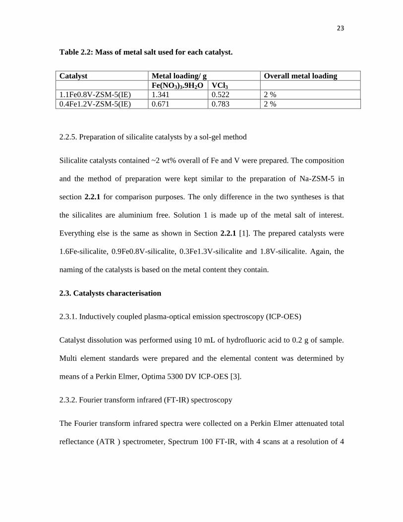
Table 2.2: Mass of metal salt used for each catalyst.
Catalyst Metal loading/ g Overall metal loading
Fe(NO3)3.9H2O VCl3
1.1Fe0.8V-ZSM-5(IE) 1.341 0.522 2 %
0.4Fe1.2V-ZSM-5(IE) 0.671 0.783 2 %
2.2.5. Preparation of silicalite catalysts by a sol-gel method
Silicalite catalysts contained ~2 wt% overall of Fe and V were prepared. The composition
and the method of preparation were kept similar to the preparation of Na-ZSM-5 in
section 2.2.1 for comparison purposes. The only difference in the two syntheses is that
the silicalites are aluminium free. Solution 1 is made up of the metal salt of interest.
Everything else is the same as shown in Section 2.2.1 [1]. The prepared catalysts were
1.6Fe-silicalite, 0.9Fe0.8V-silicalite, 0.3Fe1.3V-silicalite and 1.8V-silicalite. Again, the
naming of the catalysts is based on the metal content they contain.
2.3. Catalysts characterisation
2.3.1. Inductively coupled plasma-optical emission spectroscopy (ICP-OES)
Catalyst dissolution was performed using 10 mL of hydrofluoric acid to 0.2 g of sample.
Multi element standards were prepared and the elemental content was determined by
means of a Perkin Elmer, Optima 5300 DV ICP-OES [3].
2.3.2. Fourier transform infrared (FT-IR) spectroscopy
The Fourier transform infrared spectra were collected on a Perkin Elmer attenuated total
reflectance (ATR ) spectrometer, Spectrum 100 FT-IR, with 4 scans at a resolution of 4
24
cm-1
and scan speed of 0.2 cm-1
s-1
[4]. Pyridine adsorption for the catalysts was
performed at room temperature until saturation. The saturation period was one hour [9].
2.3.3. X-ray diffraction (XRD)
The X-ray diffraction was carried out using a Bruker AXS D8 Advance diffractometer
using Cu Kα radiation. The data was collected between 5 and 60° (2θ) at the rate of 1°
min-1
with a 0.02 scanning step size [4, 5].
2.3.4. Braunauer Emmet Teller (BET surface area) and porosity measurements
Nitrogen–BET surface area and porosity measurements were performed using a
Micromeretics Gemini 2375 instrument. Samples weighing from 0.06 to 0.075 g were
degassed from room temperature to 200 °C at an initial step rate of 1°C/min overnight
before carrying out the measurements. The surface area measurements were performed at
a temperature of -196 °C [6-7].
2.3.5. Transmission electron microscopy (TEM)
Transmission Electron Microscope (TEM) images were obtained from a JEOL JEM
1010. Sample preparation was done by taking a small amount of the sample into a small
vial and adding methanol. Before analysis, the samples are put under sonication for about
10 minutes. Thereafter the copper grid is dipped into the sample using a small clipper to
hold the grid and then put under a light to dry the sample on the grid.
2.3.6. Scanning electron microscopy (SEM)
Samples were mounted on an aluminium stub using double sided carbon tape and were
subsequently coated with a Au sputter coat using a Bio-Rad E5200 Auto sputter coater.

25
The coated samples were then analysed using a Zeiss ULTRA 55 FEGSEM. The
instrument has a field emission tungsten hairpin filament with a ZrO reserve, as an
electron source [8].
2.4. Gas Chromatographs
The reaction products were analysed by a PerkinElmer Auto System GC equipped with
Flame Ionisation Detector using a Pona 50 × 0.20mm× 0.5 μm column [4] and results
quantification analysis was carried out by using internal response factors. The internal
response factor (K) of each product was calculated by finding the ratio of a known
amount of product over a constant amount of 1,2-dichlorobenzene (internal standard)
using the following equation.
K = [(Area IS) * (Amount SC)] / [(Amount IS * area SC)]
K = Internal Response Factor
IS = Internal Standard
SC = Specific compound of interest
Detailed products quantification calculations are in the Appendix.

26
2.5. Chemicals and reagents
The n-octane used as the feed during catalytic testing was of ≥ 99.0 % purity and
acquired from Fluka. The gas chromatograph standards (1-octanol, 2-octanol, 3-octanol,
4-octanol, octanal, 2-octanone, 3-octanone, 4-octanone, 1,2-dichlorobenzene) used to
determine response factors were supplied by Sigma-Aldrich and were also of high purity.
For ICP-OES all standards (Fe, Si, Al, Mn, Co, V, and Na) were 1000 ppm and obtained
from Polychem Supplies. Hydrofluoric acid (40 %) was obtained from Riedel-de-Haën
and used for digestion of the precursors and catalysts.
The metal salts used in the catalytic synthesis were obtained from Merck and the
minimum purity of the salts was ≥ 97 %. The precursors (40 % colloidal silica,
tetrapropylammoniumbromide and sodium chloride) used for all the zeolite and
sillicalites synthesis were supplied by Sigma-Aldrich. The sodium silica solution was
obtained from UniTEK chemical suppliers, with a SiO2 purity of ≥ 50 %.

27
References
1. S. Narayanan, A. Sultana, P. Meriaudeau, C. Naccache , A. Auroux, C. Viornery,
Appl. Catal., A-Gen., 143, 1996, 342.
2. L.O. Öhmana, B. Ganemib, E. Björnbom, K. Rahkamaa, R.L. Keiski, J. Paul,
Mater. Chem. Phys., 73, 2002, 267.
3. Method of ICP analysis, Süd Chemie, South Africa.
4. M.N. Cele, H.B. Friedrich, M. D. Bala, Catal. Commun., 57, 2014, 102.
5. Instrumental methods of analysis, L.L. Meritt, J.A. Dean, New York, 1974.
6. B. –Z. Zhan, B. Modén, J. Dakka, J. G. Santiesteban, E. Iglesia, J. Catal., 245,
2007, 316.
7. D. Topaloglu Yazıcı, C. Bilgic, Surf. Interface Anal., 42, 2010, 962.
8. M. Volpe, G. Tonetto, H. de Lasa, Appl. Catal. A-Gen., 272, 2004, 78.
28
Chapter Three Activation of n-octane using different
transition metals in ZSM-5 3.1. Introduction
The chemistry of metals in the periodic table differs according to the group and the
period they belong to. The metals that provided the most interesting properties in
catalysis over the years are the transition metals. These metals are known as the d-group
elements and they have one outermost orbital filled with electrons next to the partially
filled d-orbitals. The partially filled d-orbitals are filled as you go across from left to right
of the periodic table and thus the stability of the metal increases. Properties of these
metals differ from one to the next. The ability of these metals to have multiple oxidation
states makes them suitable materials for catalysis. Transition metals are able to accept
electrons (oxidising agents) and also donate electrons (reducing agents). Therefore the
oxidising ability of transition metals is expected to decrease across from left to right of
the table, with some irregularities when it comes to chromium, and copper as their outer s
orbital is only filled with one electron [1-3].
Previous studies have been carried out to show the different properties of different
transition metals used in a same application. Anipsitakis and Dionysiou tested nine
transition metals for the activation of different oxidants and radical generation. From this
study they postulated that the redox behaviour of metals in solutions relies on the size,
charge, metal hydrolysis and also complexation with other counter-ions present in the
reaction media [3].
29
Stein et al. studied the active metals in the oxidation of different hydrocarbons. These
ranged from straight chain hydrocarbons to branched and cyclic. They used many oxides
of different metals, such as oxides of cobalt, chromium, iron, manganese, nickel, cerium,
thorium, aluminium, titanium, lead, vanadium, magnesium, copper, zinc, tungsten,
silicon, and zirconium. When oxidizing pentane and heptane they found that cobalt was
the most active metal, followed by chromium, iron, manganese and nickel respectively.
Other metals were found to be moderately active and vanadium was found to be the least
active. One other interesting finding was that the reactivity increased with molecular
weight in a given homologous series [4]. The products of these reactions were the alkenes
together with some cracked products.
The aim of this study is to obtain oxygenated products. A question is whether the trend of
reactivity differs with the type of reaction products one forms?
3.1.1 Synopsis of this chapter
The aim of the work reported in this chapter is to identify the transition metals that will
give best catalysts in terms of selectivity and conversion. In this case, the selectivity
refers to the terminal oxygenated products. Thereafter, the metals that give the best
results will be taken further to synthesise another set of catalysts, such as bimetallic
catalysts of ZSM-5 and silicalite.

30
3.2. Experimental
3.2.1. Catalyst synthesis and characterisation
Na-ZSM-5 was prepared as described in Section 2.2.1 and Fe-ZSM-5, V-ZSM-5, Cr-
ZSM-5 and Mn-ZSM-5 catalysts were prepared as described in Section 2.2.2 [18].
Catalysts characterization is described in Section 2.3.
3.2.2 Catalyst testing
All the reactions carried out were under nitrogen atmosphere. In a typical test run, 13 mL
of acetonitrile was added into a two-neck round bottom flask (50 mL) fitted with a
stopper and a condenser. This was followed by the consecutive addition of 1.8 mmol of
n-octane, 16 mmol of H2O2 (30 wt% in water) and 0.1 g catalyst. The reactions were
conducted at 80 C for 8 hours. The products of the reaction were analysed and
quantified by Perkin Elmer Auto System GC equipped with a Flame Ionisation Detector
using a Pona 50 x 0.20 mm x 0.5 μm column, (See Appendix for calculations). The
residual H2O2 was quantified by titrating 3 mL of the reaction solution acidified with 0.2
M H2SO4 with 0.02 M KMnO4 [5, 6]. Chlorobenzene was used as an internal standard.
3.3. Results and Discussion
3.3.1 Catalyst characterisation
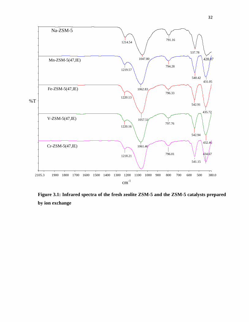
Looking at all the FT-IR spectra (Figure 3.1) of the prepared samples, they all show the
same pattern of peaks. These peaks were assigned according to the Flanigen-Khatami-
Szymanski correlation [7]. The absorptions around 1060, 790 and 430 cm-1
are assigned
to Si and AlO4 tetrahedra internal and external symmetric vibrations. The presence of
double rings of tetrahedra in the framework gives rise to the band around 650 – 540 cm-1
.
31
Bands appearing around 1220 cm-1
are attributed to an external asymmetrical stretching
vibration of SiO2 and also indicate the formation of ZSM-5 with 3D channel morphology
[7, 8, 9]. There are no bands near 1600 cm-1
which could be assigned to the bending of
molecular adsorbed water, which confirms the presence of BrØnsted acid sites on the
zeolite catalysts [10, 11].
The FT-IR spectra also agree with the XRD data on the purity and the crystallinity of the
catalysts prepared (see Section 2.2.2). By taking the ratios of the bands at about 430 and
540, one can characterize the presence of the zeolite framework. The ratio of these two
peaks (optical density ratio) is reported to be close to 0.7-0.8 [7]. The value is less than
0.7 for materials with amorphous silica. All the catalysts prepared showed an optical
density ratio of greater than 0.7.
The powder XRD diffractograms of all the prepared catalysts showed the pure phase
ZSM-5 pattern (Figure 3.2) [19]. The peaks at 6-9, 22-24 and 45º confirm the presence
of an MFI structure [19]. The intensity of the peaks confirms that the prepared zeolite
catalysts are crystalline and pure. This is further confirmed by the FT-IR optical density
ratio (Figure 3.1) [12]. Another observable feature of the diffractograms are the
similarities between the parent Na-ZSM-5 and the ionic exchange modified zeolites. This
confirms the structural stability of the ZSM-5 materials, hence no observable change is
seen when modified under different conditions and methods. No peaks are seen at 38.7
and 41.6 2 values for the Fe-ZSM-5(47,IE) catalysts. The absence of these peaks
suggests the absence of the iron haematite phase [13, 14].
32
Figure 3.1: Infrared spectra of the fresh zeolite ZSM-5 and the ZSM-5 catalysts prepared
by ion exchange
2105.3 1900 1800 1700 1600 1500 1400 1300 1200 1100 1000 900 800 700 600 500 380.0
cm-1
%T
Cr-ZSM-5(47,IE)
V-ZSM-5(47,IE)
Fe-ZSM-5(47,IE)
Mn-ZSM-5(47,IE)
Na-ZSM-5
1214.54
1047.80
791.16
537.78 428.07
1219.57
1062.83
794.28
540.42 431.05
1220.13
1057.51
796.33
542.91 435.72
1220.16
1061.46
797.76
542.94 432.46
1218.21 796.01 541.15
434.67
33
Figure 3.2: p-XRD diffractogram of (A) Na-ZSM-5, (B) Fe-ZSM-5(47,IE), (C) Mn-ZSM-
5(47,IE), (D) V-ZSM-5(47,IE), (E) Cr-ZSM-5(47,IE)
Adsorption and porosity characteristics of the parent and for the ion exchanged zeolites
derived from nitrogen adsorption-desorption isotherms are given in Table 3.1. The BET
surface area differed with the metal loaded on the zeolite. The iron exchanged zeolite
showed higher surface area compared to all the other catalysts.
There is no observable trend from the chemical properties of the metals that explains the
different surface areas obtained for the catalysts.
Lin
(C
ounts
)
2-Theta - Scale
5 10 20 30 40 50 60
A
B
C
D
E

34
Table 3.1: Surface properties and ICP results.
Catalysts BET m2/g Pore Volume cm
3/g ICP / %Wt.
Na-ZSM-5 326.7 0.18 -
Fe-ZSM-5(47,IE) 413.2 0.20 1.6
Mn-ZSM-5(47,IE) 310.8 0.18 1.7
Cr-ZSM-5(47,IE) 329.9 0.21 1.6
V-ZSM-5(47,IE) 354.1 0.19 1.7
There was a small change observed for the pore volumes of the ion-exchanged zeolites
compared to the parent zeolites for all the ion exchanged zeolites. This suggests that there
is no pore blocking effect of the exchanged metals. These results can also be supported
by the powder XRD data which confirms the absence of other phases apart from the
ZSM-5 phase [14]. Metal loading on the zeolite did not change the structure of the parent
ZSM-5, this is further confirmed by the FT-IR and p-XRD data.
According to the SEM analysis (Figure 3.3), the synthesized ZSM-5 catalysts have
similar morphology to one another. The catalysts have the MFI-typical morphology
which is the lath-shape [15]. Depending on the template used to prepare the zeolite, the
morphology may differ, and this is because different templates have different tendencies
in filling in the channels, hence leading to different crystal growth orientation [15]. The
other most common morphologies of zeolites are hexagonal-like shape and ellipsoidal
shaped crystals [15]. Some spheroidal crystals are observed for the catalysts as a result of
the presence of Na+ [15].
35
TEM analysis also compliments the results of the SEM analysis, the images clearly show
the spherical shape of the zeolite catalysts (Figure 3.4).
Figure 3.3: SEM images of (A) Na-ZSM-5, (B) Mn-ZSM-5(47,IE), (C) Fe-ZSM-5(47,IE),
(D) V-ZSM-5(47,IE), (E) Cr-ZSZSM-5(47,IE)
A B
C D
E

36
C
A B
D
E
Figure 3.4: TEM images of (A) Na-ZSM-5, (B) Mn-ZSM-5(47,IE), (C) Fe-ZSM-5(47,IE),
(D) V-ZSM-5(47,IE), (E) Cr-ZSZSM-5(47,IE)
37
3.3.2 Catalyst testing
After fully characterizing the prepared catalysts, Fe-ZSM-5(47,IE) was chosen to perform
some reaction condition optimisation studies for this part of the work. This catalyst was
used to carry out reactions to find the optimum oxidant (H2O2) ratio for the reaction. The
catalyst was also used to obtain the optimum reaction time for the oxidation of n-octane
to terminal oxygenated products. The temperature to carry out these reactions was chosen
to be 80 °C because previous work has shown that this is the optimum temperature for
related compounds [16-17]. Also, this is the boiling point of acetonitrile.
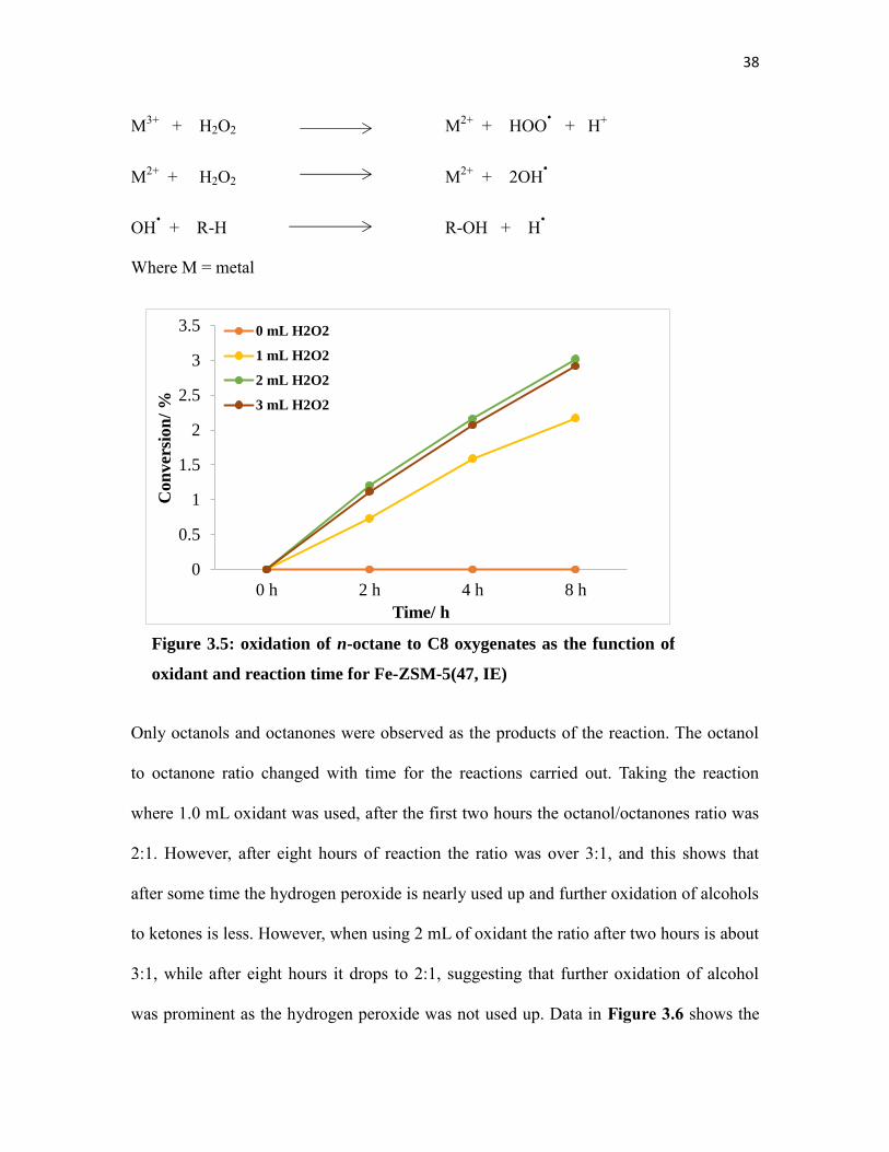
The data in Figure 3.5 shows that in the presence of H2O2, the overall conversion of
octane to the corresponding oxygenates gradually increases with time. The rate of
increase in conversion is dependent to the amount of oxidant used in the reaction. When
more oxidant was added to the reaction there were more products produced as a function
of time. This is shown by the slopes of the graphs in Figure 3.5, which become steeper
when more oxidant is used. It is also seen in the figure that excess oxidant does not lead
to even faster rates. The slopes when 2 mL or 3 mL of oxidant are added are essentially
the same. This may be due to limited active sites on the catalyst. Using 2 or 3 mL of
oxidant thus gives similar conversions, and the highest conversion obtained was about 3
%. The generally low conversions may be due to the rate of diffusion of products from
the ZSM-5 structure channels and pores. This is known to be a limiting factor in similar
reactions [16]. The reaction mechanism using peroxide oxidants is believed to follow the
radical reaction which results in the formation of radicals which then react with the
organic molecule to produce alcohols, aldehyde and ketones as follows:
38
M3+
+ H2O2 M2+
+ HOO.
+ H+
M2+
+ H2O2 M2+
+ 2OH.
OH. + R-H R-OH + H
.
Where M = metal
Only octanols and octanones were observed as the products of the reaction. The octanol
to octanone ratio changed with time for the reactions carried out. Taking the reaction
where 1.0 mL oxidant was used, after the first two hours the octanol/octanones ratio was
2:1. However, after eight hours of reaction the ratio was over 3:1, and this shows that
after some time the hydrogen peroxide is nearly used up and further oxidation of alcohols
to ketones is less. However, when using 2 mL of oxidant the ratio after two hours is about
3:1, while after eight hours it drops to 2:1, suggesting that further oxidation of alcohol
was prominent as the hydrogen peroxide was not used up. Data in Figure 3.6 shows the
0
0.5
1
1.5
2
2.5
3
3.5
0 h 2 h 4 h 8 h
Con
ver
sion
/ %
Time/ h
0 mL H2O2
1 mL H2O2
2 mL H2O2
3 mL H2O2
Figure 3.5: oxidation of n-octane to C8 oxygenates as the function of
oxidant and reaction time for Fe-ZSM-5(47, IE)
39
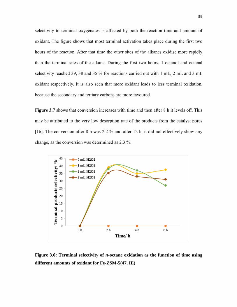
selectivity to terminal oxygenates is affected by both the reaction time and amount of
oxidant. The figure shows that most terminal activation takes place during the first two
hours of the reaction. After that time the other sites of the alkanes oxidise more rapidly
than the terminal sites of the alkane. During the first two hours, 1-octanol and octanal
selectivity reached 39, 38 and 35 % for reactions carried out with 1 mL, 2 mL and 3 mL
oxidant respectively. It is also seen that more oxidant leads to less terminal oxidation,
because the secondary and tertiary carbons are more favoured.
Figure 3.7 shows that conversion increases with time and then after 8 h it levels off. This
may be attributed to the very low desorption rate of the products from the catalyst pores
[16]. The conversion after 8 h was 2.2 % and after 12 h, it did not effectively show any
change, as the conversion was determined as 2.3 %.
Figure 3.6: Terminal selectivity of n-octane oxidation as the function of time using
different amounts of oxidant for Fe-ZSM-5(47, IE)
0
5
10
15
20
25
30
35
40
45
0 h 2 h 4 h 8 h
Ter
min
al
pro
du
cts
sele
ctiv
ity/
%
Time/ h
0 mL H2O2
1 mL H2O2
2 mL H2O2
3 mL H2O2

40
0
0.5
1
1.5
2
2.5
0 5 10 15
Con
ver
sion
/ %
Time/ h
1.0 mL H2O2
Figure 3.7: oxidation of n-octane to C8 oxygenates as the function of reaction time
for Fe-ZSM-5(47, IE)
Thus, the conversion was found to be stationery after 8 hours of reaction. Therefore, the
combination of 8 hours reaction time and 1 mL oxidant at 80 °C was used to carry out
further tests to establish the scope of the catalytic process for the Fe-ZSM-5(47,IE), V-
ZSM-5(47,IE), Cr-ZSM-5(47,IE) and Mn-ZSM-5(47,IE) catalysts. The conversion and
selectivities of the catalysts were compared as shown in Figure 3.8. It was observed that
Fe-ZSM-5(47,IE) showed better selectivity (37 %) to terminal products compared to the
other three catalysts at a conversion of 2.2 %. The Cr-ZSM-5(47,IE), V-ZSM-5(47,IE)
and Mn-ZSM-5(47,IE) showed 10, 12 and 6 % selectivity to terminal products at
conversions of 5.1, 6.6 and 3.3 % respectively.

41
0
1
2
3
4
5
6
7
0
5
10
15
20
25
30
35
40
Fe-ZSM-5(47,IE) Cr-ZSM-5(47,IE) V-ZSM-5(47,IE) Mn-ZSM-5(47,IE)
% C
on
ver
sio
n
% C
1 S
elec
tivit
y
Catalyst
Selectivity Conversion
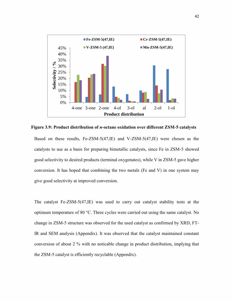
Figure 3.9 shows the reaction products distribution over the tested catalysts. Nearly all
the catalysts show a similar trend of products, with higher selectivities to over oxidation
products. Fe-ZSM-5 was the only exception to this trend, where alcohols were more
dominant than ketones. This means that the Fe-ZSM-5(47,IE) catalyst inhibits the
overoxidation of the primary products. This may be attributed to the low activity
possesed by Fe-ZSM-5(47,IE). No cracking products were observed for any catalysts
under any of the conditions employed [16].
Figure 3.8: Catalytic results of n-octane oxidation over different ZSM-5 catalysts
42
0%
5%
10%
15%
20%
25%
30%
35%
40%
45%
4-one 3-one 2-one 4-ol 3-ol al 2-ol 1-ol
Sel
ecti
vit
y /
%
Product distribution
Fe-ZSM-5(47,IE) Cr-ZSM-5(47,IE)
V-ZSM-5 (47,IE) Mn-ZSM-5(47,IE)
Based on these results, Fe-ZSM-5(47,IE) and V-ZSM-5(47,IE) were chosen as the
catalysts to use as a basis for preparing bimetallic catalysts, since Fe in ZSM-5 showed
good selectivity to desired products (terminal oxygenates), while V in ZSM-5 gave higher
conversion. It has hoped that combining the two metals (Fe and V) in one system may
give good selectivity at improved conversion.
The catalyst Fe-ZSM-5(47,IE) was used to carry out catalyst stability tests at the
optimum temperature of 80 °C. Three cycles were carried out using the same catalyst. No
change in ZSM-5 structure was observed for the used catalyst as confirmed by XRD, FT-
IR and SEM analysis (Appendix). It was observed that the catalyst maintained constant
conversion of about 2 % with no noticable change in product distribution, implying that
the ZSM-5 catalyst is efficiently recyclable (Appendix).
Figure 3.9: Product distribution of n-octane oxidation over different ZSM-5 catalysts

43
3.4. Conclusions
Analysis of the catalysts by p-XRD and FT-IR showed that there were no additional
phases other than ZSM-5. Also, the optical density ratio obtained proved that the zeolites
were crystalline. Introduction of transition metals to the Na-ZSM-5 by ionic exchange
does not alter the overall structure of the zeolite. The oxidation of n-octane to their
corresponding oxygenates increased as a function of time until eight hours, after which it
starts to levels off. When different oxidant amounts were used, the conversion correlated
to the amount of oxidant used, up to a conversion of about 3 %. Using more oxidant lead
to over oxidation of primary products (alcohols) to secondary products (ketones), hence
the reaction with 1.0 mL oxidant showed a ratio of more than 3:1 to alcohols/ ketones
while using more oxidant gave a ratio of 2:1. Furthermore, using 1 mL of oxidant gave
higher selectivity towards 1-octanol and octanal.
Reactions carried out using the Fe-ZSM-5(47,IE) catalyst gave a conversion of 2.2 %,
with selectivity to terminal oxygenates of 37 %, which was higher than those of the other
three catalysts used for the same reaction under the same conditions. The vanadium
catalyst gave a conversion of 6.6 %. The Fe-ZSM-5 catalyst prepared was stable under
optimum reaction conditions and was used for three cycles without losing any of its
activity.

44
References
1. http://www.4college.co.uk/a/ss/catalyst.php, Date Accessed: February 2016.
2. http://2012books.lardbucket.org/books/principles-of-general-chemistry-v1.0/s27-
01-general-trends-among-the-trans.html, Date Accessed: February 2016.
3. G.P. Anipsitakis, D. D. Dionysiou, Environ. Sci. Technol., 2004, 38, 3712.
4. K. C. Stein, J. J. Feenan, G. P. Thompson, I J. F. Shultz, L. J. E. Hofer, and R. B.
Anderson, Ind. Eng. Chem., 1960, VOL. 52, NO. 8, 174.
5. Flinn ChemTopic™ Labs, Volume 16, Oxidation and Reduction; Cesa, I. Ed.,
Flinn Scientific: Batavia, IL 2004.
6. M.V. Balarama Krishna, K. Chandrasekaran, D. Karunasagar, J. Arunachalam, J
Hazard Mater, B84, 2001, 240.
7. G. Coudurier, C. Naccache, J.C. Vedrine, J. Chem. Soc. Chem. Commun., 1982,
1413.
8. V.D. Gaag, ZSM-5 Type Zeolites: Synthesis and Use in Gas Phase Reaction with
Ammonia, Technische Universiteit, Delft, 1987.
9. D.J. Kim, H.S. Chung, Appl. Clay Sci., 24, 2003, 77.
10. W. Panpa, S. Jinawath, Appl. Catal., B: Environ., 90, 2009, 394.
11. M.M. Mohamed, F.I. Zidan, M. Thabet, Micropor Mesopor Mat., 108, 2008, 203.
12. F.J. van der Gaag, J.C. Jansen, H. van Bekkum, Zeolites, 4, 1984, 369.
13. M.A. Ali, B. Brisdon, W.J. Thomas, Appl. Catal. A: Gen. 252, 2003, 162.
14. B. Michalkiewicz, Appl. Catal. A, 277, 2004, 147.
15. S. Sang, F. Chang, Z. Liu, C. He, Y. He, L. Xu, Catal. Today, 95, 2004, 734.
16. M. N. Cele, H.B. Friedrich, M. D. Bala, Reac. Kinet. Mech. Cat., 111, 2014, 750.

45
17. M.N. Cele, H.B. Friedrich, M. D. Bala, Catal. Commun., 57, 2014, 102.
18. S. Narayanan, A. Sultana, P. Meriaudeau, C. Naccache , A. Auroux, C. Viornery,
Appl. Catal., A-Gen., 143, 1996, 342.
19. M.M.J. Treacy, J.B. Hinggins, R. von Ballmoos, Collection of Simulated XRD
Powder Patterns for Zeolites, Third Revised Edition, 1990, 525.
46
Chapter Four Preparation of the bimetallic zeolite
catalysts for the oxidation of n-octane to
terminal oxygenates
4.1. Introduction
Different metals have different catalytic properties. Some metals are not active for certain
catalytic processes when they are not supported by other metals, and some work well
individually and get retarded when they are mixed with other metals in the same catalytic
reaction. However, it is generally true that most metals can enhance catalysts in one or two
ways. Metals either enhance a catalyst to be highly selective with low conversion, or a highly
active catalyst (gives good conversion but with poor selectivity) [1]. To tackle this challenge,
chemists and engineers have investigated ways to using more than one metal per catalyst to
try and improve the skewed catalytic performance.
For the purpose of this work, the focus was on previous work that was carried out using
zeolites, more especially ZSM-5, since this is a good basis for this work, which also deals
with ZSM-5 type zeolite catalysts. However, it should be mentioned that lot of work has been
reported using non-zeolite bimetallic catalysts for the oxidation of different substrates.
From the work reported by Jodaei et al. [2], H-ZSM-5 based bimetallic catalysts were used to
oxidize ethyl acetate. For this work, Ag was used as the primary metal of the catalysts and
three other transition metals were used in order to promote the catalytic activity. The catalysts
were prepared by ion exchange and the metals employed were Fe, Mn and Co. The results of
the reactions showed that the activity of the bimetallic system was higher than that of the
47
individual components. The activities of the catalysts with respect to transition metals were
observed to follow the sequence: Fe > Co > Mn [2].
Forde et al. reported work on the oxidation of methane using a Cu-Fe-ZSM-5 catalyst
prepared by chemical vapour decomposition. For this work hydrogen peroxide was employed
as the oxidant. The results of the work showed that when Fe-ZSM-5 was used as a catalyst,
an activity of 15.8 mol product kg (cat) -1
h-1
could be achieved and when a bimetallic catalyst
was employed, activity of 11.4 mol product kg (cat) -1
h-1
was obtained. The work also
showed that upon the introduction of the second metal, such as Cu, the selectivity of alcohol
increases, while that of formic acid decreases. The selectivity to methanol was 12 and 78
mol% when Fe-ZSM-5 and Cu-Fe-ZSM-5 were used respectively [1].
No previous work was found reporting the oxidation of n-octane to oxygenates for bimetallic
ZSM-5 zeolites and silicalites. Most previous work reported on the use of bimetallic ZSM-5
zeolites and silicalites focuses on dehydrogenation reactions and also on the oxidation of
volatile organic compounds (VOCs) and the reduction of NOx [3-9].
The the aim of this work was to explore the oxidation of n-octane using ZSM-5 bimetallic
systems prepared from vanadium and iron. This work continues from the work discussed in
the previous chapter, and it is looking at integrating the two metals in one catalyst in the hope
that they will synergistically work together to give a catalyst that is more active with good
selectivity towards terminal oxygenates.
For this part of the work, a total of eight catalysts were prepared and tested to see the effect of
adding vanadium into Fe-ZSM-5 with a Si/Al ratio of 46 and Fe-Silicalite catalysts in the
oxidation of n-octane. For both the ZSM-5 and the silicalite, different ratios of Fe and V were
used to study any effect. The intention was to discover if the introduction of vanadium to the
Fe based zeolite catalysts will have any effect on the conversion and selectivity of the
48
reaction. The catalysts prepared for this part of the work were 1.6Fe-ZSM-5(IE), 1.7V-ZSM-
5(IE), 1.1Fe0.8V-ZSM-5(IE), 0.4Fe1.2V-ZSM-5(IE), 1.6Fe-Silicalite, 1.8V-Silicalite,
0.9Fe0.8V-Silicalite, and 0.3Fe1.3V-Silicalite. The numbers in the catalyst name correspond
to the metal weight percent in the catalyst, IE refers to ion exchange.
4.2. Experimental
4.2.1. Catalyst synthesis and characterisation
The 1.6Fe-ZSM-5(IE) and 1.7V-ZSM-5(IE) catalysts were prepared as previously described
in Section 2.2.2. The 1.1Fe0.8V-ZSM-5(IE) and 0.4Fe1.2V-ZSM-5(IE) catalysts were
prepared as described in Section 2.2.4 and the silicalite catalysts preparation method is
described in Section 2.2.5. Catalysts characterization is described in Section 2.3.
4.2.2 Catalyst testing
As reported in the previous chapter, the reactions were carried out under nitrogen
atmosphere. Due to the low activities shown by the silicalite catalysts, the testing conditions
were modified. Thus 18 mL of acetonitrile was added into a two-neck round bottom flask (50
mL) fitted with a stopper and a condenser. This was followed by the consecutive addition of
1.8 mmol of n-octane, 0.25 g catalyst and 16 mmol of H2O2 (30 wt% in water). The reaction
temperature and time were kept constant at 80 C and 8 hours respectively. The products of
the reaction were analysed by a Perkin Elmer Auto System GC equipped with a Flame
Ionisation Detector using a Pona 50 x 0.20 mm x 0.5 μm column. The internal standard was
kept as chlorobenzene.
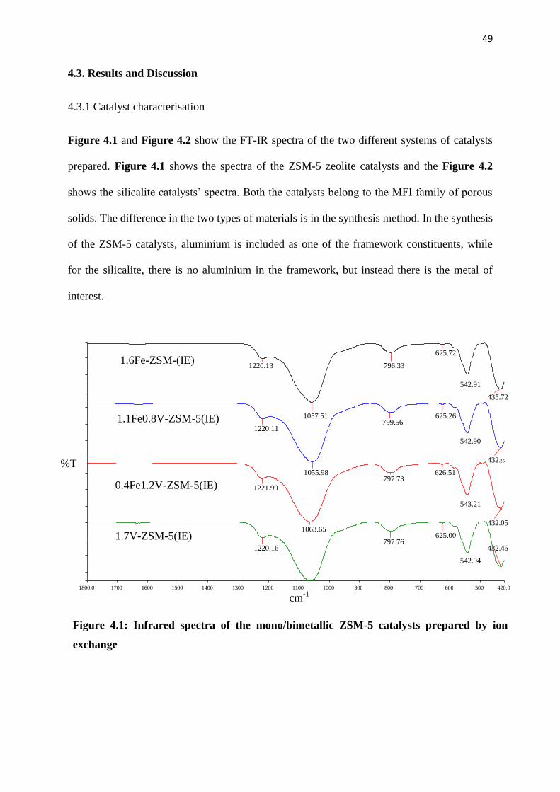
49
1800.0 1700 1600 1500 1400 1300 1200 1100 1000 900 800 700 600 500 420.0 cm
-1
%T
1.7V-ZSM-5(IE)
0.4Fe1.2V-ZSM-5(IE)
1.1Fe0.8V-ZSM-5(IE)
1.6Fe-ZSM-(IE) 1220.13
1057.51
796.33 625.72
542.91 435.72
1220.11
1055.98
799.56 625.26
542.90
432.25
1221.99
1063.65
797.73 626.51
543.21
432.05
1220.16 797.76 625.00
542.94 432.46
4.3. Results and Discussion
4.3.1 Catalyst characterisation
Figure 4.1 and Figure 4.2 show the FT-IR spectra of the two different systems of catalysts
prepared. Figure 4.1 shows the spectra of the ZSM-5 zeolite catalysts and the Figure 4.2
shows the silicalite catalysts’ spectra. Both the catalysts belong to the MFI family of porous
solids. The difference in the two types of materials is in the synthesis method. In the synthesis
of the ZSM-5 catalysts, aluminium is included as one of the framework constituents, while
for the silicalite, there is no aluminium in the framework, but instead there is the metal of
interest.
Figure 4.1: Infrared spectra of the mono/bimetallic ZSM-5 catalysts prepared by ion
exchange

50
1800.0 1700 1600 1500 1400 1300 1200 1100 1000 900 800 700 600 500 380.0 cm
-1
%T
1.8V-Silicalite
0.3Fe1.3V-Silicalite
0.9Fe0.8V-Silicalite
1.6Fe-Silicalite
1069.67
798.73 544.11
435.96
1220.11
1055.98
799.56 625.26
542.90
432.25
1224.69
1066.34
798.97 626.92
544.33
434.86
1225.24 800.82 628.16
545.10 433.57
The two types of catalysts show the same FT-IR absorption bands, proving that they belong
to the same MFI family. Absorptions for Si and AlO4/MO4 tetrahedra internal (where M =
metal) and external symmetric vibrations are found at around 1060, 790 and 430 cm-1
. The
bands at around 650-540 cm-1
are assigned to the double rings of tetrahedra in the framework.
The external asymmetrical stretching vibration of SiO2 is always shown by a strong band
around 1220 cm-1
. This is the band that confirms the ZSM-5 structure with 3D channel
morphology [10-14]. The purity and crystallinity of the prepared catalysts was confirmed by
the optical density ratios which agree with the literature [10]. All the catalysts show a value
greater than 0.7 for the optical density ratio [10].
Figure 4.2: Infrared spectra of the mono/bimetallic silicalite catalysts prepared by ion
exchange

51
Lin
(C
ounts
)
2-Theta - Scale 5 10 20 30 40 50 60
D
C
B
A
Figure 4.3: p-XRD diffractogram of (A) 1.6Fe-ZSM-5(IE), (B) 1.1Fe0.8V-ZSM-5(IE),
(C) 0.4Fe1.2V-ZSM-5(IE), (D) 1.7V-ZSM-5(IE)
The p-XRD patterns of the two sets of catalysts (Figure 4.3 and Figure 4.4) are similar,
showing the true fingerprint of the MFI material. The intensity of the peaks agrees with the
FT-IR results, showing the crystalline nature of the catalysts. Importantly, for the Fe based
catalysts, no haematite phase lines are observed at 38.7 and 41.6 2 [15, 16].
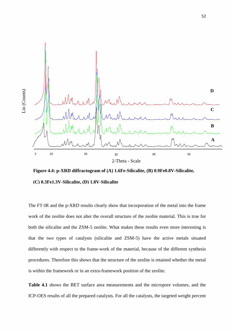
52
0
2-Theta - Scale
5 10 20 30 40 50 60
Lin
(C
ounts
)
5 20 10 30 50 40
A
B
C
D
Figure 4.4: p-XRD diffractogram of (A) 1.6Fe-Silicalite, (B) 0.9Fe0.8V-Silicalite,
(C) 0.3Fe1.3V-Silicalite, (D) 1.8V-Silicalite
The FT-IR and the p-XRD results clearly show that incorporation of the metal into the frame
work of the zeolite does not alter the overall structure of the zeolite material. This is true for
both the silicalite and the ZSM-5 zeolite. What makes these results even more interesting is
that the two types of catalysts (silicalite and ZSM-5) have the active metals situated
differently with respect to the frame-work of the material, because of the different synthesis
procedures. Therefore this shows that the structure of the zeolite is retained whether the metal
is within the framework or in an extra-framework position of the zeolite.
Table 4.1 shows the BET surface area measurements and the micropore volumes, and the
ICP-OES results of all the prepared catalysts. For all the catalysts, the targeted weight percent
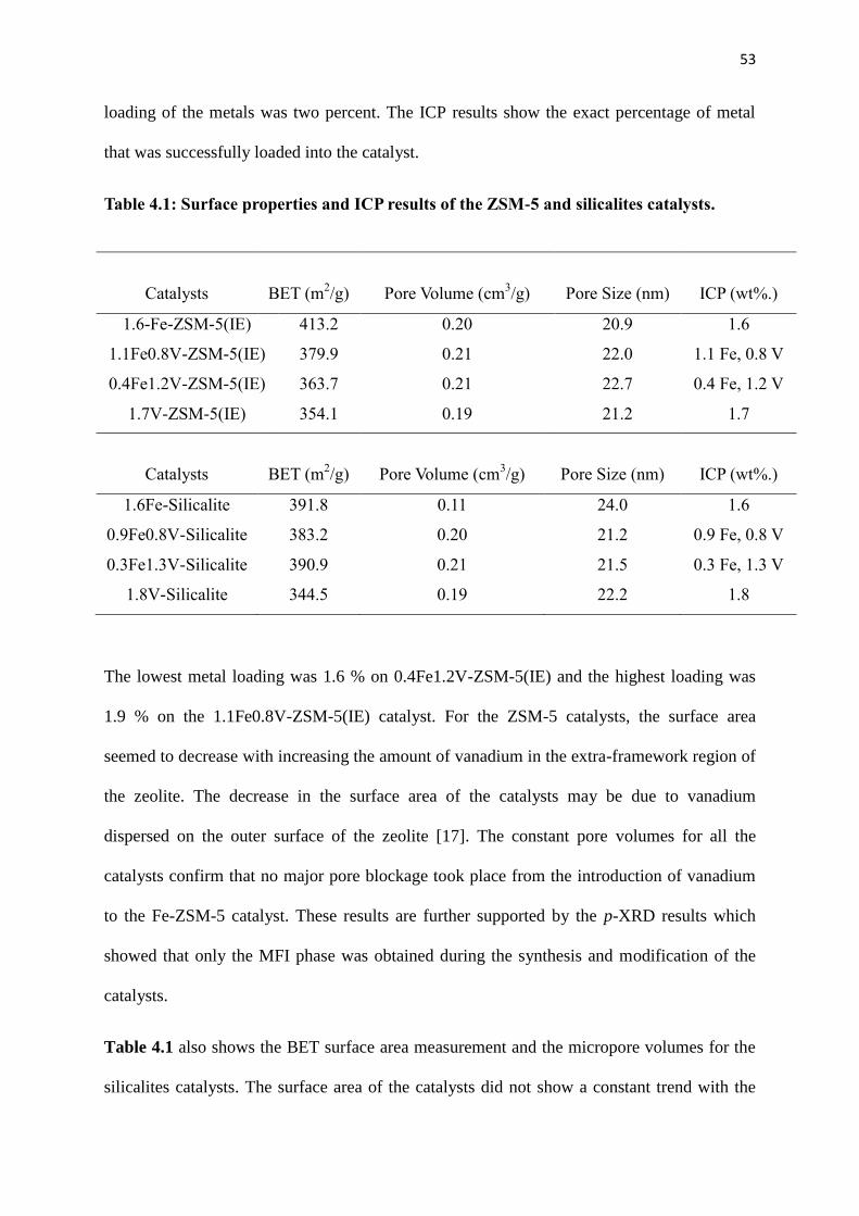
53
loading of the metals was two percent. The ICP results show the exact percentage of metal
that was successfully loaded into the catalyst.
Table 4.1: Surface properties and ICP results of the ZSM-5 and silicalites catalysts.
The lowest metal loading was 1.6 % on 0.4Fe1.2V-ZSM-5(IE) and the highest loading was
1.9 % on the 1.1Fe0.8V-ZSM-5(IE) catalyst. For the ZSM-5 catalysts, the surface area
seemed to decrease with increasing the amount of vanadium in the extra-framework region of
the zeolite. The decrease in the surface area of the catalysts may be due to vanadium
dispersed on the outer surface of the zeolite [17]. The constant pore volumes for all the
catalysts confirm that no major pore blockage took place from the introduction of vanadium
to the Fe-ZSM-5 catalyst. These results are further supported by the p-XRD results which
showed that only the MFI phase was obtained during the synthesis and modification of the
catalysts.
Table 4.1 also shows the BET surface area measurement and the micropore volumes for the
silicalites catalysts. The surface area of the catalysts did not show a constant trend with the
Catalysts BET (m2/g) Pore Volume (cm
3/g) Pore Size (nm) ICP (wt%.)
1.6-Fe-ZSM-5(IE) 413.2 0.20 20.9 1.6
1.1Fe0.8V-ZSM-5(IE) 379.9 0.21 22.0 1.1 Fe, 0.8 V
0.4Fe1.2V-ZSM-5(IE) 363.7 0.21 22.7 0.4 Fe, 1.2 V
1.7V-ZSM-5(IE) 354.1 0.19 21.2 1.7
Catalysts BET (m2/g) Pore Volume (cm
3/g) Pore Size (nm) ICP (wt%.)
1.6Fe-Silicalite 391.8 0.11 24.0 1.6
0.9Fe0.8V-Silicalite 383.2 0.20 21.2 0.9 Fe, 0.8 V
0.3Fe1.3V-Silicalite 390.9 0.21 21.5 0.3 Fe, 1.3 V
1.8V-Silicalite 344.5 0.19 22.2 1.8
54
metal loaded, but again the catalyst with the lowest surface area was the 1.8V-Silicalite. The
pore volumes of the three catalysts with vanadium loading were similar to one another, while
the pore volume for Fe-Silicalite was very low compared to the other three catalysts. The
decrease in the pore volume of the Fe-Silicalite may be due to possible pore reaction resulting
from the size of the atomic radii of iron which is relatively higher than that of vanadium. This
may be possible since the metal is in the framework of the catalyst in this case.
From the SEM analysis (Figure 4.5) of the different sets of catalysts, it is clear that all
catalysts have similar shapes. The Zeolite ZSM-5 catalysts have a more lath-like shape than
the silicalite catalysts. This could be attributed to the different crystallinities that the catalysts
have. According to Sang et al., a high Si/Al ratio improves crystallinity of the catalysts [18].
Hence, the silicalites with the higher Si/M ratio will have higher crystallinity as well as less
lath-like shape. The overall shape of all the catalysts is the same and that is of the typical MFI
material (hexagonal). Another factor that can explain the difference in crystallinity is that for
low silica zeolite samples, the crystallisation time in the reactor was 36 hours and for the high
silica zeolite samples it was 48 to 60 hours. The difference in times was because, as the
molar ratio of SiO2/Al2O3 increases, the induction period becomes longer. The presence of
Na+ gives rise to the spheroidal crystals observed in the catalysts images [18].

55
Figure 4.5: SEM images of (A) 1.6Fe-ZSM-5(IE), (B) 1.1Fe0.8V-ZSM-5(IE), (C)
0.4Fe1.2V-ZSM-5(IE), (D) 1.7V-ZSM-5(IE), (E) 1.6Fe-Silicalite, (F) 0.9Fe0.8V-Silicalite,
(G) 0.3Fe1.3V-Silicalite, (H) 1.8V-Silicalite
A B
C D
F
G H
E A B
C D
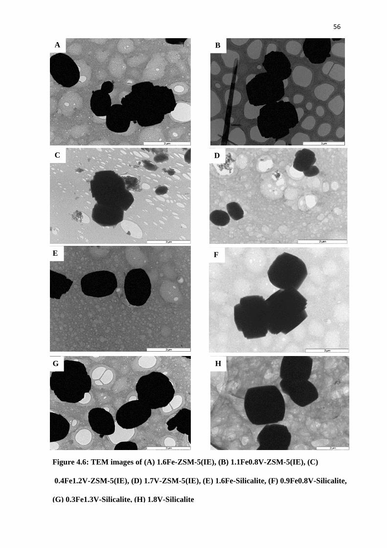
56
Figure 4.6: TEM images of (A) 1.6Fe-ZSM-5(IE), (B) 1.1Fe0.8V-ZSM-5(IE), (C)
0.4Fe1.2V-ZSM-5(IE), (D) 1.7V-ZSM-5(IE), (E) 1.6Fe-Silicalite, (F) 0.9Fe0.8V-Silicalite,
(G) 0.3Fe1.3V-Silicalite, (H) 1.8V-Silicalite
A B
C
G H
D
E F
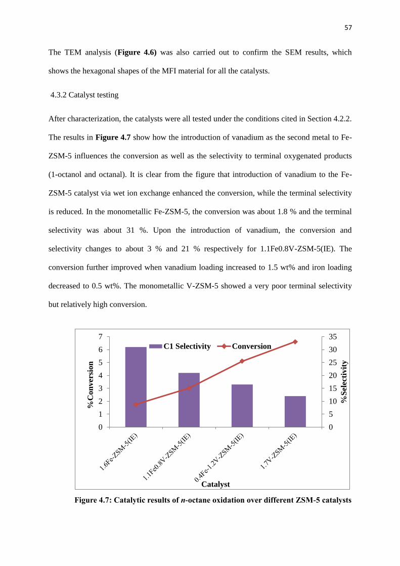
57
The TEM analysis (Figure 4.6) was also carried out to confirm the SEM results, which
shows the hexagonal shapes of the MFI material for all the catalysts.
4.3.2 Catalyst testing
After characterization, the catalysts were all tested under the conditions cited in Section 4.2.2.
The results in Figure 4.7 show how the introduction of vanadium as the second metal to Fe-
ZSM-5 influences the conversion as well as the selectivity to terminal oxygenated products
(1-octanol and octanal). It is clear from the figure that introduction of vanadium to the Fe-
ZSM-5 catalyst via wet ion exchange enhanced the conversion, while the terminal selectivity
is reduced. In the monometallic Fe-ZSM-5, the conversion was about 1.8 % and the terminal
selectivity was about 31 %. Upon the introduction of vanadium, the conversion and
selectivity changes to about 3 % and 21 % respectively for 1.1Fe0.8V-ZSM-5(IE). The
conversion further improved when vanadium loading increased to 1.5 wt% and iron loading
decreased to 0.5 wt%. The monometallic V-ZSM-5 showed a very poor terminal selectivity
but relatively high conversion.
Figure 4.7: Catalytic results of n-octane oxidation over different ZSM-5 catalysts
0
5
10
15
20
25
30
35
0
1
2
3
4
5
6
7%
Sel
ecti
vit
y
%C
on
ver
sion
Catalyst
C1 Selectivity Conversion
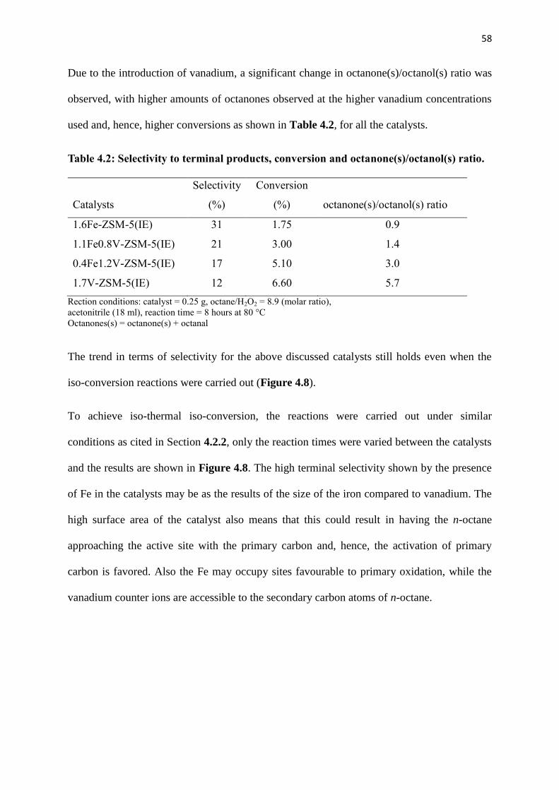
58
Due to the introduction of vanadium, a significant change in octanone(s)/octanol(s) ratio was
observed, with higher amounts of octanones observed at the higher vanadium concentrations
used and, hence, higher conversions as shown in Table 4.2, for all the catalysts.
Table 4.2: Selectivity to terminal products, conversion and octanone(s)/octanol(s) ratio.
Catalysts
Selectivity
(%)
Conversion
(%) octanone(s)/octanol(s) ratio
1.6Fe-ZSM-5(IE) 31 1.75 0.9
1.1Fe0.8V-ZSM-5(IE) 21 3.00 1.4
0.4Fe1.2V-ZSM-5(IE) 17 5.10 3.0
1.7V-ZSM-5(IE) 12 6.60 5.7
Rection conditions: catalyst = 0.25 g, octane/H2O2 = 8.9 (molar ratio),
acetonitrile (18 ml), reaction time = 8 hours at 80 °C
Octanones(s) = octanone(s) + octanal
The trend in terms of selectivity for the above discussed catalysts still holds even when the
iso-conversion reactions were carried out (Figure 4.8).
To achieve iso-thermal iso-conversion, the reactions were carried out under similar
conditions as cited in Section 4.2.2, only the reaction times were varied between the catalysts
and the results are shown in Figure 4.8. The high terminal selectivity shown by the presence
of Fe in the catalysts may be as the results of the size of the iron compared to vanadium. The
high surface area of the catalyst also means that this could result in having the n-octane
approaching the active site with the primary carbon and, hence, the activation of primary
carbon is favored. Also the Fe may occupy sites favourable to primary oxidation, while the
vanadium counter ions are accessible to the secondary carbon atoms of n-octane.
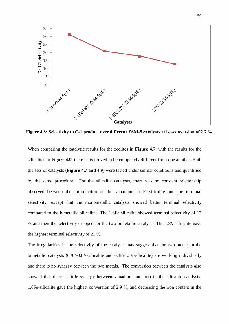
59
0
5
10
15
20
25
30
35
% C
1 S
elec
tivit
y
Catalysts
When comparing the catalytic results for the zeolites in Figure 4.7, with the results for the
silicalites in Figure 4.9, the results proved to be completely different from one another. Both
the sets of catalysts (Figure 4.7 and 4.9) were tested under similar conditions and quantified
by the same procedure. For the silicalite catalysts, there was no constant relationship
observed between the introduction of the vanadium to Fe-silicalite and the terminal
selectivity, except that the monometallic catalysts showed better terminal selectivity
compared to the bimetallic silicalites. The 1.6Fe-silicalite showed terminal selectivity of 17
% and then the selectivity dropped for the two bimetallic catalysts. The 1.8V-silicalite gave
the highest terminal selectivity of 21 %.
The irregularities in the selectivity of the catalysts may suggest that the two metals in the
bimetallic catalysts (0.9Fe0.8V-silicalite and 0.3Fe1.3V-silicalite) are working individually
and there is no synergy between the two metals. The conversion between the catalysts also
showed that there is little synergy between vanadium and iron in the silicalite catalysts.
1.6Fe-silicalite gave the highest conversion of 2.9 %, and decreasing the iron content in the
Figure 4.8: Selectivity to C-1 product over different ZSM-5 catalysts at iso-conversion of 2.7 %
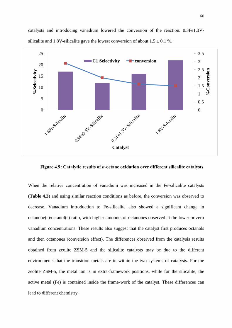
60
0
0.5
1
1.5
2
2.5
3
3.5
0
5
10
15
20
25
%C
on
ver
sion
%S
elec
tiv
ity
Catalyst
C1 Selectivity conversion
catalysts and introducing vanadium lowered the conversion of the reaction. 0.3Fe1.3V-
silicalite and 1.8V-silicalite gave the lowest conversion of about 1.5 ± 0.1 %.
When the relative concentration of vanadium was increased in the Fe-silicalite catalysts
(Table 4.3) and using similar reaction conditions as before, the conversion was observed to
decrease. Vanadium introduction to Fe-silicalite also showed a significant change in
octanone(s)/octanol(s) ratio, with higher amounts of octanones observed at the lower or zero
vanadium concentrations. These results also suggest that the catalyst first produces octanols
and then octanones (conversion effect). The differences observed from the catalysis results
obtained from zeolite ZSM-5 and the silicalite catalysts may be due to the different
environments that the transition metals are in within the two systems of catalysts. For the
zeolite ZSM-5, the metal ion is in extra-framework positions, while for the silicalite, the
active metal (Fe) is contained inside the frame-work of the catalyst. These differences can
lead to different chemistry.
Figure 4.9: Catalytic results of n-octane oxidation over different silicalite catalysts

61
0
5
10
15
20
25
%C
-1 S
elec
tivit
y
Catalyst
Table 4.3: Selectivity to terminal products, conversion and octanone(s)/octanol(s) ratio
Catalysts
Selectivity
(%)
Conversion
(%) octanone(s)/octanol(s) ratio
1.6Fe-silicalite 17 2.90 2.2
0.9Fe0.8V-silicalite 12 2.00 1.6
0.3Fe1.3V-silicalite 16 1.6 1.3
1.8V-silicalite 22 1.5 0.9
Rection conditions: catalyst = 0.25 g, octane/H2O2 = 8.9 (molar ratio),
acetonitrile (18 ml), reaction time = 8 hours at 80 °C
Octanones(s) = octanone(s) + octanal
The C-1 selectivity trend on the silicalite catalysts was also maintained at iso-conversion of
1.7 % (Figure 4.10) using the average conversion of four repeat reactions carried out.
Figure 4.10: Selectivity to C-1 product over different silicalite catalysts at
iso-conversion of 1.7 %

62
0
0.5
1
1.5
2
2.5
Cycle 1 Cycle 2 Cycle 3
% C
on
ver
sion
Catalyst cycle
4.3.3 Catalyst stability test
Catalyst 0.9Fe0.8V-silicalite was used to carry out catalyst stability tests at the optimum
temperature of 80 °C. Three cycles were carried out using the same catalyst. No change in
silicalite structure was observed for the used catalyst as confirmed by XRD, FT-IR and SEM
analysis (Appendix). It was observed that the catalyst maintained constant conversion of
about 1.9 % with no noticeable change in product distribution, implying that the silicalite
catalyst is efficiently recyclable (Figure 4.11).
Figure 4.11: Conversion data after three reaction cycles using recycled
0.9Fe0.8V-silicalite under optimum conditions
63
4.4. Conclusions
Successful syntheses of the ZSM-5 zeolite and silicalite monometallic and bimetallic
catalysts were confirmed by p-XRD and FT-IR. ZSM-5 zeolite catalysts were prepared by
ionic exchange and silicalite catalysts were prepared by isomorphic substitution. The ICP-
OES showed that all catalysts contained the active metals at reported values. The BET
surface areas for the zeolite catalysts decreased with the introduction of vanadium, while the
pore volumes remained constant, suggesting little or no pore blocking by the metals.
Reducing the concentration of Fe and introducing vanadium into the zeolite ZSM-5 catalysts
improved the conversion, while reducing the selectivity to primary oxygenated products
(octanal and 1-octanol).
When using the silicalite catalysts, there was no correlation between the concentration of Fe
and V in the catalysts with respect to the selectivity to terminal oxygenates, but reducing the
Fe content lead to a decrease in the conversion of the reaction. For both catalysts, the
octanone(s)/octanol(s) ratio had the same relationship with the conversion. For higher
conversions more ketones were forming compared to alcohols, suggesting that ketones are a
result of secondary oxidation. 0.9Fe0.8V-Silicalite gave a conversion of 2.0 % with
octanone(s)/octanol(s) ratio of 1.6, while 1.1Fe0.8V-ZSM-5(IE) gave 3.0 % conversion and a
ratio of 1.4. The recyclability of 0.9Fe0.8V-Silicalite was explored and it also proved to be
stable over three cycles under optimum conditions.

64
References
1. M. M. Forde, R. D. Armstrong, R. McVicker, P. P. Wells, N. Dimitratos, Q. He, L.
Lu, R.L. Jenkins, C. Hammond, J.A. Lopez-Sanchez, C. J. Kiely, G. J. Hutchings,
Chem. Sci., 2014, 5, 3616.
2. A. Jodaei, D. Salari, A. Niaei, M. Khatamian, N. Çaylak, Environmen. Technol., 32,
2011, 406.
3. Y. Zhang, Y. Zhou, A. Qiu, Y. Wang, Y. Xu, P. Wu, Catal. Commun. 7, 2006, 866
4. L. R. Raddi de Araujo, Martin Schmal, Appl. Catal., A: 235, 2002, 147
5. S.E. Maisuls, K. Seshan, S. Feast, J.A. Lercher, Appl. Catal., B: Environmental 29,
2001, 81.
6. P. Nakhostin Panahi, D. Salari, A. Niaei, S.M. Mousavi, J. Ind. Eng. Chem. 19, 2013,
1799.
7. L. Li, F. Zhang, N. Guan, M. Richter, R. Fricke, Catal. Commun., 8, 2007, 588.
8. A.Z. Abdullah, M. Z. Abu Bakar, S. Bhatia, J. Hazard. Mater., B129, 2006, 49.
9. B. Izadkhah, S.R. Nabavi, A. Niaei, D. Salari, T. Mahmuodi Badiki, N. ҫaylak, J. Ind.
and Eng. Chem., 18, 2012, 2091.
10. G. Coudurier, C. Naccache, J.C. Vedrine, J. Chem. Soc., Chem. Commun., 1982
11. V.D. Gaag, ZSM-5 Type Zeolites: Synthesis and Use in Gas Phase Reaction with
Ammonia, Technische Universiteit, Delft, 1987.
12. D.J. Kim, H.S. Chung, App. Clay Science., 24, 2003, 77.
13. K. Iwakai, T. Tago, H. Konno, Y. Nakasaka, T. Masuda, Microporous and
Mesoporous Mater., 141, 2011, 174.
14. S. Barot, R. Bandyopadhyay, Nanoscience. Nanotech., 6(1A), 2016, 112.
15. M.A. Ali, B, Brisdon, W.J. Thomas, Appl. Catal., A: 252, 2003, 162.

65
16. B. Michalkiewicz, Appl. Catal., A, 277, 2004, 147.
17. M. Mhamdi, S. Khaddar-Zine, A. Ghorbel, React. Kinet. Catal. Lett., 88, 2006, 149.
18. S. Sang, F. Chang, Z. Liu, C. He, Y. He, L. Xu, Catal. Today 73, 2004, 95.
66
Chapter Five Oxidation of n-octane to terminal
oxygenates using Fe-ZSM-5 and silicalite
catalysts
5.1. Introduction
In catalysis, the chemistry of transition metals depends on their environment and the support
they are on. For zeolites, transition metals can be incorporated into the framework using
different techniques and this leads to different chemistry of the catalysts. The commonly
known methods of incorporating transition metals into the zeolite are isomorphic substitution,
vapor deposition (CVD) and ionic exchange [1, 2]. Different methods result in different
catalytic environments, i.e. ionic exchange results in the transition metal in the extra-
framework positions of the zeolite, while isomorphic substitution puts the metal into the
framework of the zeolite. Apart from that, with isomorphic substitution one can also tune the
zeolite catalyst further. From this method, two catalysts can be prepared having similar MFI
structures, but different constituents, i.e. zeolite ZSM-5 contains aluminium in its framework
and silicalite does not have aluminium. Scheme 5.1 and Scheme 5.2 show how the metal
occupies the frame-work of the zeolite ZSM-5 and silicalite prepared by isomorphic
substitution respectively.
Previous studies have shown that silicalites can be used in the oxidation of paraffins to
terminal oxygenates [3-5]. Table 5.1 shows that different silicalite catalysts can be used for
this type of reaction, but it also shows that these catalysts give very low selectivities to
primary oxidation products. The exception, Fe-silicalite-1, gave 93 % C-1 selectivity only
because methane was the substrate for this reaction.
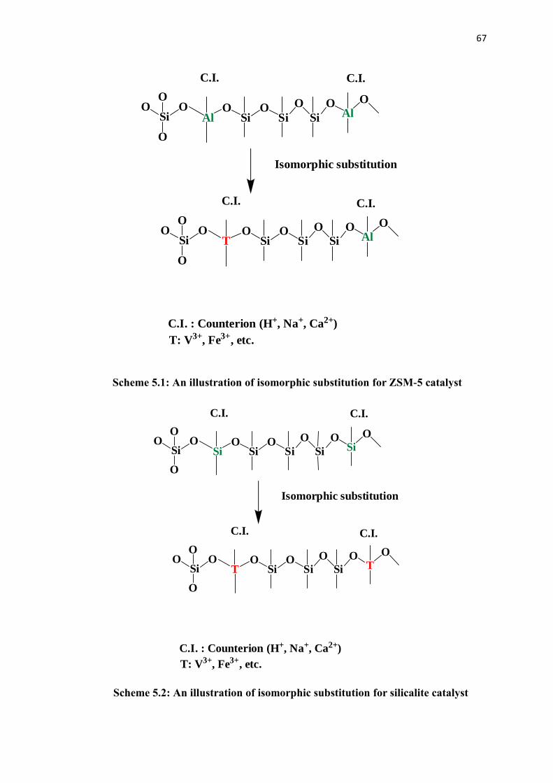
67
SiOO
O
O
SiO
SiO
Si
O
Si
OSi
O
SiOO
O
O
TO
SiO
Si
O
Si
OT
O
Isomorphic substitution
C.I. C.I.
C.I. C.I.
C.I. : Counterion (H+, Na+, Ca2+)
T: V3+, Fe3+, etc.
SiOO
O
O
AlO
SiO
Si
O
Si
OAl
O
SiOO
O
O
TO
SiO
Si
O
Si
OAl
O
Isomorphic substitution
C.I. C.I.
C.I. C.I.
C.I. : Counterion (H+, Na+, Ca2+)
T: V3+, Fe3+, etc.
Scheme 5.1: An illustration of isomorphic substitution for ZSM-5 catalyst
Scheme 5.2: An illustration of isomorphic substitution for silicalite catalyst
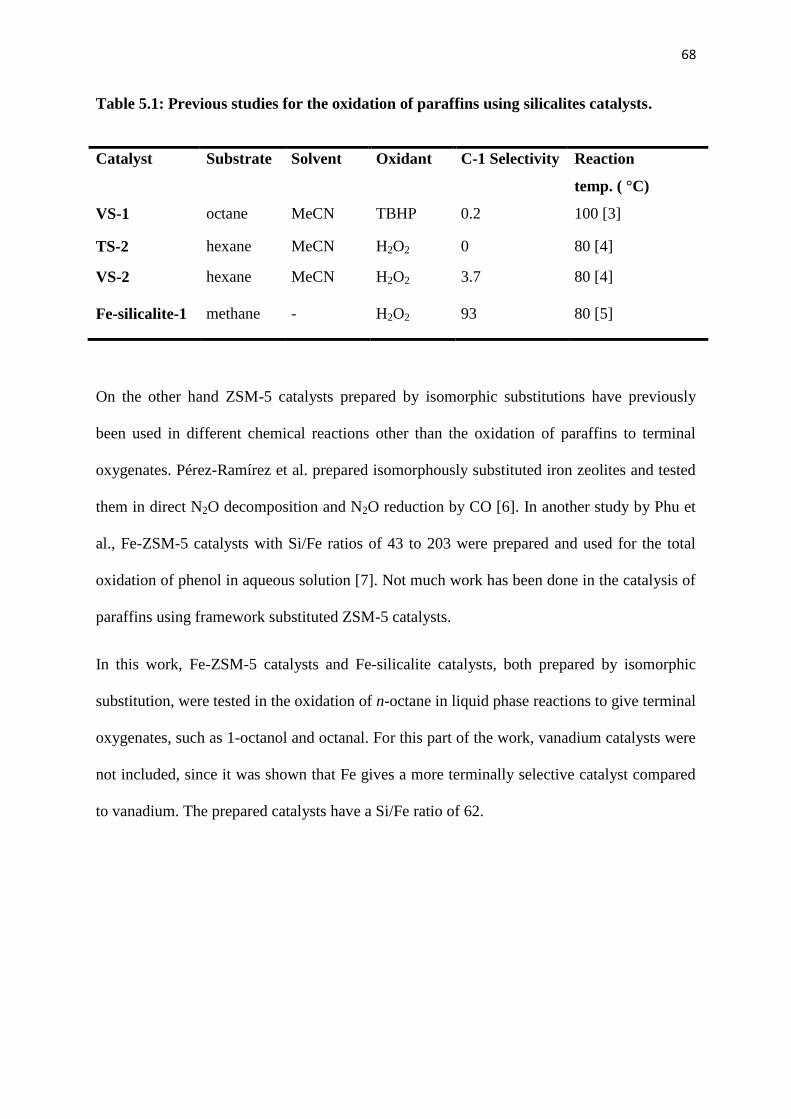
68
Table 5.1: Previous studies for the oxidation of paraffins using silicalites catalysts.
On the other hand ZSM-5 catalysts prepared by isomorphic substitutions have previously
been used in different chemical reactions other than the oxidation of paraffins to terminal
oxygenates. Pérez-Ramírez et al. prepared isomorphously substituted iron zeolites and tested
them in direct N2O decomposition and N2O reduction by CO [6]. In another study by Phu et
al., Fe-ZSM-5 catalysts with Si/Fe ratios of 43 to 203 were prepared and used for the total
oxidation of phenol in aqueous solution [7]. Not much work has been done in the catalysis of
paraffins using framework substituted ZSM-5 catalysts.
In this work, Fe-ZSM-5 catalysts and Fe-silicalite catalysts, both prepared by isomorphic
substitution, were tested in the oxidation of n-octane in liquid phase reactions to give terminal
oxygenates, such as 1-octanol and octanal. For this part of the work, vanadium catalysts were
not included, since it was shown that Fe gives a more terminally selective catalyst compared
to vanadium. The prepared catalysts have a Si/Fe ratio of 62.
Catalyst Substrate Solvent Oxidant C-1 Selectivity Reaction
temp. ( °C)
VS-1 octane MeCN TBHP 0.2 100 [3]
TS-2 hexane MeCN H2O2 0 80 [4]
VS-2 hexane MeCN H2O2 3.7 80 [4]
Fe-silicalite-1 methane - H2O2 93 80 [5]
69
5.2. Experimental
5.2.1. Catalyst synthesis and characterisation
The framework substituted Fe-ZSM-5(62) and the Fe-silicalite(62) catalysts’ preparation is
described in Section 2.2.3 and 2.2.5 respectively. The characterization of both catalysts is
described in Section 2.3.
5.2.2 Catalyst testing
The procedure for catalyst testing is the same as described in the previous chapter (Chapter
4). The reactions were carried out under nitrogen. The reactions for the two catalysts were
carried out in 18 mL of acetonitrile in a two-necked round bottomed flask (50 mL), fitted
with a stopper and a condenser. This was followed by the consecutive addition of 1.8 mmol
of n-octane, 0.25 g catalyst and 16 mmol of H2O2 (30 wt% in water). The reaction
temperature and time were kept constant at 80 C and 8 hours. The products of the reaction
were analysed by a Perkin Elmer Auto System GC equipped with a Flame Ionisation Detector
(FID) using a Pona 50 x 0.20 mm x 0.5 μm column. The internal standard for the reaction
was chlorobenzene (0.04 g).
In order to test for active metal leaching, the solution was filtered off at the reaction
temperature in order to prevent any soluble metal from readsorbing onto the catalyst surface
on cooling [15]. The filtrate was put back in the reaction flask to react further with any
soluble metal present in the reaction solution. After removal of the catalyst by filtration after
3 h or 4 h, the filtrate was allowed to react for 8 h or 9 h respectively, which allowed a
comparison of conversion to a run with a catalyst.
70
5.3. Results and Discussion
5.3.1 Catalyst characterisation
Fe-silicalite(62) is the same catalysts as 1.6Fe-Silicalite. For the purpose of this chapter, the
nomenclature was changed to Fe-silicalite(62) since for this chapter, the Si/Fe ratio in both
the catalysts is being compared instead of the Si/Al ratio. The number in the parenthesis
denotes the Si/Fe ratio.
The FT-IR characterization (Figure 5.1) for Fe-silicalite(62) was previously discussed in
Section 4.3.1. It was shown that it was indeed an MFI material. The results were further
supported by the p-XRD (Figure 5.2), which also showed that the synthesized material had
an MFI finger print and the intensity of the peaks showed the crystalline nature of the catalyst
[12]. The crystallinity of the material was further supported by the optical density ratio,
which was found to be above 0.7 [8-11].
The isomorphously substituted Fe-ZSM-5 FT-IR data, shown in Figure 5.1, corresponded to
those of typical MFI materials. The band around 550 cm-1
of the Fe-ZSM-5(62) is assigned to
the 5-membered rings in the MFI lattice [9]. The other characteristic bands are the same as
for the Fe-silicalite(62) and they were discussed in Section 4.3.1.
The p-XRD pattern for the Fe-ZSM-5(62) is similar to the patterns of all the previously
prepared catalysts. All peak positions matched those reported for the MFI-structure [12] and
no-impurity phase was observed. The low background and high intensity of the peaks in the
prepared catalysts also indicates the high crystallinity of the material [7].

71
1800.0 1700 1600 1500 1400 1300 1200 1100 1000 900 800 700 600 500 380.0 cm-1
%T Fe-silicalite(62)
Fe-ZSM-5(62)
1221.45 798.17
543.32
434.14
1069.99
800.44 546.34
441.97
1224.30
The BET surface area measurements and the micropore volumes (Table 5.1) show that
despite having almost similar metal loadings (1.4 % and 1.6 %), the two different catalysts
Figure 5.1: Infrared spectra of the Fe-silicalite(62) and Fe-ZSM-5(62) catalysts prepared
by isomorphic substitution
2-Theta - Scale 5 10 20 30 40 50 60
Fe-silicalite(62)
Fe-ZSM-5(62)
Lin
(C
ounts
)
Figure 5.2: p-XRD of the Fe-silicalite(62) and Fe-ZSM-5(62) catalysts prepared by
isomorphic substitution

72
have different surface area and also different pore volumes. Fe-ZSM-5(62), which contains
Al in its framework, has a smaller surface area and larger pore volume compared to Fe-
silicalite(62), which does not contain Al in its framework, The small surface area of the
ZSM-5 may be due to aluminium species inside the zeolite pores and channels which may
also widen the pores of the zeolite [13]. The absence of aluminium in the framework of
silicalites results in relatively small pore volumes. If four metal atoms are present in the
framework (Al, Si, Fe and O) the increase in the pore volume will be anticipated [14].
Silicalites have only three metal atoms (Si, Fe and O), hence the pore volume is different
from that of the Fe-ZSM-5(62).
Table 5.2: Surface properties and ICP results of the ZSM-5 and silicalite catalysts.
Catalysts BET (m2/g) Pore Volume (cm
3/g) Pore Size (nm) ICP (%Wt.)
Fe-ZSM-5(62) 359 0.19 20.9 1.4
Fe-Silicalite(62) 392 0.11 24.9 1.6
B
D
Figure 5.3: (A) SEM image of Fe-ZSM-5(62), (B) SEM image of Fe-silicalite(62), (C) TEM
image of Fe-ZSM-5(62), and (D) TEM image of Fe-silicalite(62)
A
C
B A
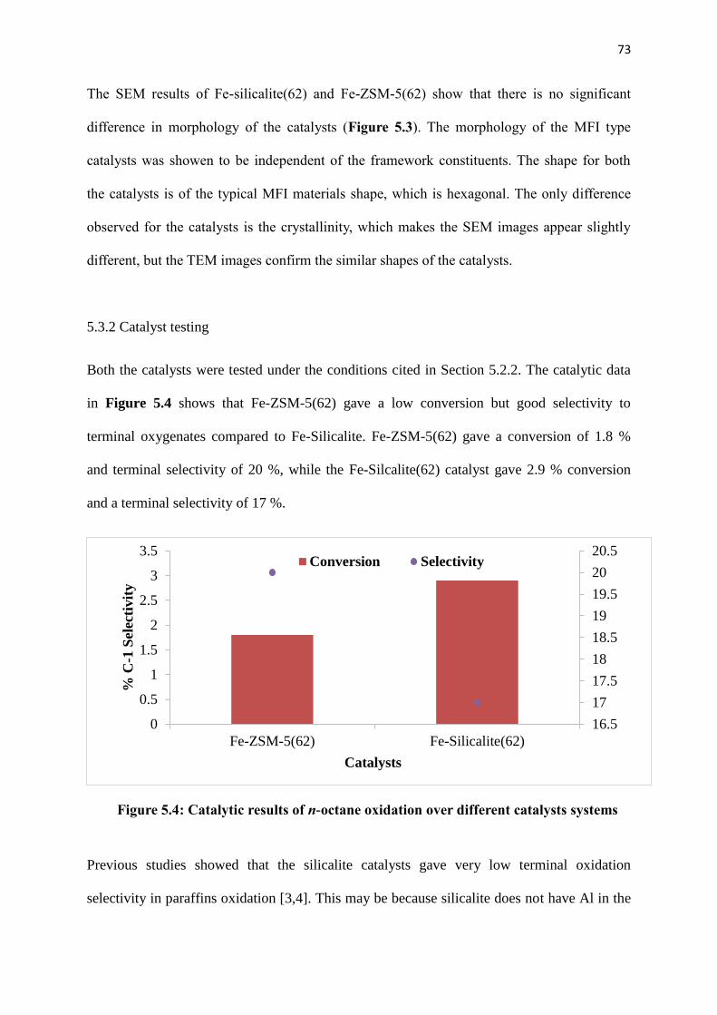
73
The SEM results of Fe-silicalite(62) and Fe-ZSM-5(62) show that there is no significant
difference in morphology of the catalysts (Figure 5.3). The morphology of the MFI type
catalysts was showen to be independent of the framework constituents. The shape for both
the catalysts is of the typical MFI materials shape, which is hexagonal. The only difference
observed for the catalysts is the crystallinity, which makes the SEM images appear slightly
different, but the TEM images confirm the similar shapes of the catalysts.
5.3.2 Catalyst testing
Both the catalysts were tested under the conditions cited in Section 5.2.2. The catalytic data
in Figure 5.4 shows that Fe-ZSM-5(62) gave a low conversion but good selectivity to
terminal oxygenates compared to Fe-Silicalite. Fe-ZSM-5(62) gave a conversion of 1.8 %
and terminal selectivity of 20 %, while the Fe-Silcalite(62) catalyst gave 2.9 % conversion
and a terminal selectivity of 17 %.
Previous studies showed that the silicalite catalysts gave very low terminal oxidation
selectivity in paraffins oxidation [3,4]. This may be because silicalite does not have Al in the
16.5
17
17.5
18
18.5
19
19.5
20
20.5
0
0.5
1
1.5
2
2.5
3
3.5
Fe-ZSM-5(62) Fe-Silicalite(62)
% C
-1 S
elec
tivit
y
Catalysts
Conversion Selectivity
Figure 5.4: Catalytic results of n-octane oxidation over different catalysts systems
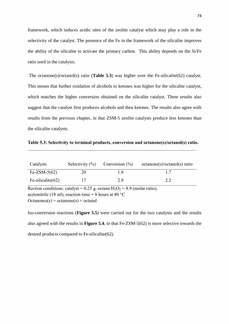
74
framework, which induces acidic sites of the zeolite catalyst which may play a role in the
selectivity of the catalyst. The presence of the Fe in the framework of the silicalite improves
the ability of the silicalite to activate the primary carbon. This ability depends on the Si/Fe
ratio used in the catalysis.
The octanone(s)/octanol(s) ratio (Table 5.3) was higher over the Fe-silicalite(62) catalyst.
This means that further oxidation of alcohols to ketones was higher for the silicalite catalyst,
which matches the higher conversion obtained on the silicalite catalyst. These results also
suggest that the catalyst first produces alcohols and then ketones. The results also agree with
results from the previous chapter, in that ZSM-5 zeolite catalysts produce less ketones than
the silicalite catalysts.
Table 5.3: Selectivity to terminal products, conversion and octanone(s)/octanol(s) ratio.
Catalysts Selectivity (%) Conversion (%) octanone(s)/octanol(s) ratio
Fe-ZSM-5(62) 20 1.8 1.7
Fe-silicalite(62) 17 2.9 2.2
Rection conditions: catalyst = 0.25 g, octane/H2O2 = 8.9 (molar ratio),
acetonitrile (18 ml), reaction time = 8 hours at 80 °C
Octanones(s) = octanone(s) + octanal
Iso-conversion reactions (Figure 5.5) were carried out for the two catalysts and the results
also agreed with the results in Figure 5.4, in that Fe-ZSM-5(62) is more selective towards the
desired products compared to Fe-silicalite(62).
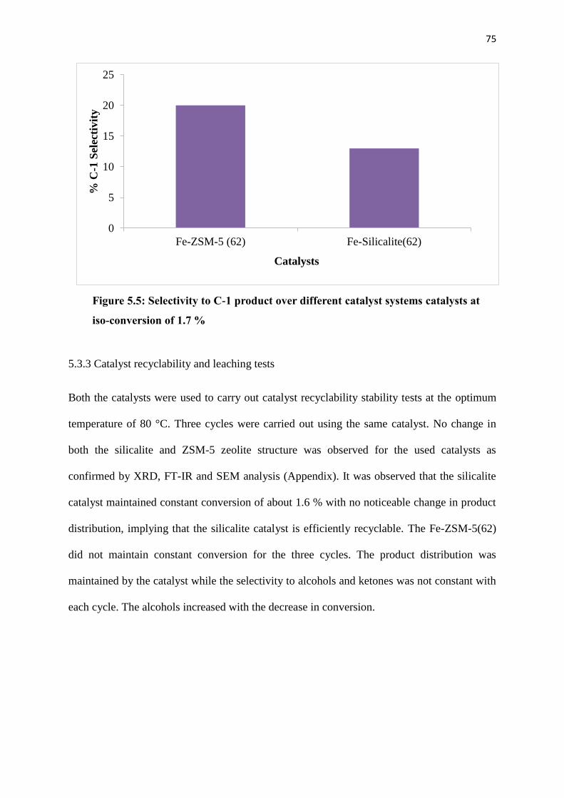
75
0
5
10
15
20
25
Fe-ZSM-5 (62) Fe-Silicalite(62)
% C
-1 S
elec
tivit
y
Catalysts
5.3.3 Catalyst recyclability and leaching tests
Both the catalysts were used to carry out catalyst recyclability stability tests at the optimum
temperature of 80 °C. Three cycles were carried out using the same catalyst. No change in
both the silicalite and ZSM-5 zeolite structure was observed for the used catalysts as
confirmed by XRD, FT-IR and SEM analysis (Appendix). It was observed that the silicalite
catalyst maintained constant conversion of about 1.6 % with no noticeable change in product
distribution, implying that the silicalite catalyst is efficiently recyclable. The Fe-ZSM-5(62)
did not maintain constant conversion for the three cycles. The product distribution was
maintained by the catalyst while the selectivity to alcohols and ketones was not constant with
each cycle. The alcohols increased with the decrease in conversion.
Figure 5.5: Selectivity to C-1 product over different catalyst systems catalysts at
iso-conversion of 1.7 %
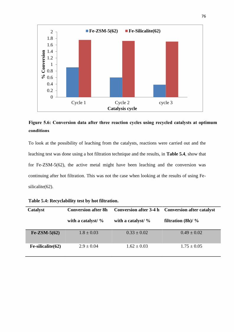
76
0
0.2
0.4
0.6
0.8
1
1.2
1.4
1.6
1.8
2
Cycle 1 Cycle 2 cycle 3
% C
on
ver
sion
Catalysis cycle
Fe-ZSM-5(62) Fe-Silicalite(62)
To look at the possibility of leaching from the catalysts, reactions were carried out and the
leaching test was done using a hot filtration technique and the results, in Table 5.4, show that
for Fe-ZSM-5(62), the active metal might have been leaching and the conversion was
continuing after hot filtration. This was not the case when looking at the results of using Fe-
silicalite(62).
Table 5.4: Recyclability test by hot filtration.
Catalyst Conversion after 8h
with a catalyst/ %
Conversion after 3-4 h
with a catalyst/ %
Conversion after catalyst
filtration (8h)/ %
Fe-ZSM-5(62) 1.8 ± 0.03 0.33 ± 0.02 0.49 ± 0.02
Fe-silicalite(62) 2.9 ± 0.04 1.62 ± 0.03 1.75 ± 0.05
Figure 5.6: Conversion data after three reaction cycles using recycled catalysts at optimum
conditions
77
5.4. Conclusions
p-XRD and FT-IR confirmed the synthesis of both the Fe-ZSM-5(62) and Fe-Silicalite(62) by
isomorphic substitution. The prepared catalysts had a Si/Fe ratio of 62, as confirmed by ICP-
OES. The presence of Al in the Fe-ZSM-5(62) decreased the BET surface area of the
catalyst. SEM and TEM analyses showed that the morphology of the two catalysts was
similar, and showed the expected hexagonal shape. The absence of Al in the framework of
the Fe-Silicalite(62) decreased the pore volume of the catalyst. Fe-ZSM-5(62) was more
selective to terminal oxidation of n-octane to oxygenates, such as octanol and octanal. The
Fe-Silicalite gave a higher conversion of 2.9 % compared to 1.8 % over the Fe-ZSM-5(62). In
both catalysts, the octanone(s)/octanol(s) ratio had the same relationship with the conversion.
Thus, for higher conversions more ketones were formed compared to alcohols, implying that
ketones are a result of secondary oxidation. The recyclability test showed that Fe-
Silicalite(62) is stable up to at least three cycles under optimum conditions, while the Fe-
ZSM-5(62) was not stable up to three cycles, with evidence of leaching.
78
References
1. P. Fejes, K. Lázár, I. Marsi, A. Rockenbauer, L. Korecz, J.B. Nagy, S. Perathoner, G.
Centi, Appl. Catal., A: Gen., 252, 2003, 75.
2. A. Wacław, K. Nowińska, W. Schwieger, Appl. Catal., A: Gen., 270, 2004, 151.
3. A.P. Singh, T. Seluam, J. M. Catal., A: Chem., 113, 1996, 497.
4. A.V. Ramaswamy, S. Sivasanker, Catal. Lett. 22, 1993, 249.
5. S. Elzey, A. Mubayi, S.C. Larsen, V.H. Grassian, J. Mol. Catal. A: Chem., 285, 2008,
48.
6. J. Pérez-Ramírez, J.C. Groenb, A. Brückner, M.S. Kumar, U. Bentrup, M.N.
Debbagh, L.A. Villaescusa, J. Catal., 232, 2005, 334.
7. N.H. Phu, T.T. Kim Hoa, N.V. Tan, H.V. Thang, P.L. Ha, Appl. Catal., B: Environ.
34, 2001, 275.
8. J.C. Jansen, F.J. van der Gaag, H. van Bekkum, Zeolites, 4, 1984, 372.
9. G. Coudurier, C. Naccache, J.C. Vedrine, J. Chem. Soc. Chem. Commun., 1982,
1413.
10. R. von Ballmoos, Ph.D. Thesis, ETH, Zürich, 1981.
11. P.A. Jacobs, H. K Beyer, Zeolites, 1, 1981, 161.
12. M.M.J. Treacy, J.B. Hinggins, R. von Ballmoos, Collection of Simulated XRD
Powder Patterns for Zeolites, Third Revised Edition, 1990, 525.
13. F. Ayari, M. Mhamdi, T. Hammedi, J. Álvarez-Rodríguez, A.R. Guerrero-Ruiz, G.
Delahay, A. Ghorbel, Appl. Catal., A: Gen., 439– 440, 2012, 100
14. M. Mhamdi, S. Khaddar-Zine, A. Ghorbel, React. Kinet. Catal. Lett., 88, 2006, 149.
15. R. A. Sheldon, M. Wallau, I.C.E. Arends and U. Schuchardt, Acc. Chem. Res., 31,
1998, 485.
79
Chapter six
Summary and Conclusion
The syntheses of Fe-ZSM-5(47,IE), Cr-ZSM-5(47,IE), Mn-ZSM-5(47,IE) and V-ZSM-
5(47,IE) were achieved using the ion-exchange method to incorporate the Fe into the extra-
framework position of the zeolite. The XRD results revealed that only the ZSM-5 phase was
obtained for all the synthesised catalysts even after modification. Studies on Fe-ZSM-
5(47,IE) showed that terminal selectivity and conversion of n-octane was time and oxidant
dependent. Furthermore, the results showed that the octanone(s)/octanol(s) ratio increases
with the amount of oxidant suggesting that octanols are primary products which upon further
oxidation resulted in octanones. Only C8 oxygenate products were obtained. The Fe-ZSM-
5(47,IE) catalyst gave a conversion of 2.7 % with the highest terminal selectivity compared to
Cr, Mn and V-ZSM-5(47,IE). V-ZSM-5 gave the highest conversion of 6.6 % and terminal
selectivity of 12 % .The XRD, FT-IR and SEM results showed that the catalysts are stable.
Fe-ZSM-5(47,IE) was used as the model catalyst for the recyclability study. It was found that
the catalyst is recyclable and the conversion of recycled catalyst was found to be the same as
of the fresh catalyst, with the same product distribution.
The syntheses of the ZSM-5 and silicalite bimetallic catalysts were successful, as only the
ZSM-5 phase was observed (by p-XRD and FT-IR). There was no change observed in the
pore volume of the bimetallic catalysts compared to the monometallic catalysts. The
selectivity to terminal products was found to be influenced by the amount of Fe and V used in
the catalysts. The introduction of V in Fe-ZSM-5 improved the conversion while decreasing
the terminal selectivity. For the silicalite catalysts, terminal selectivity was improved by the
80
introduction of V, while the conversion decreased. No clear trend for the terminal selectivity
was seen over the catalysts.
A comparative study of framework substituted Fe-ZSM-5 and Fe-silicalite was conducted.
The catalysts were prepared by isomorphic substitution and characterized by p-XRD, FT-IR,
SEM, TEM, ICP-OES and BET surface measurements. The morphology of the catalysts was
similar and showed the expected hexagonal shape. Fe-ZSM-5(62) catalysts showed higher
terminal selectivity (20 %) and lower conversion compared to Fe-silicalite(62). Only C8
oxygenate products were observed in all n-octane oxidation reactions. The product
distribution from Fe-ZSM-5(62) was found to be similar to the product distribution obtain
from the use of Fe-silicalite(62) under similar oxidation reaction conditions.
In conclusion, this work has shown that Fe-zeolite type materials are effective in the
oxidation of n-octane in the liquid phase and that good selectivity to terminal products can be
achieved. It was also shown that selectivity and conversion of the n-octane could be
controlled using bimetallic ZSM-5 catalysts.
81
APPENDIX
Supplemental information
82
Table of Content
Calculations 83
FT-IR Spectra 83
Diffractograms 84
SEM images 84
TEM images 85
Products distribution 85-87
BET measurements 87

83
Calculation of the conversion and selectivity
Xi = YiZi
∑ YiZii X100%
Where Xi is the mole fraction of component i, Zi is the response factor of component i, and
Yi is the peak area of component i. The conversion of octane is defined as the ratio of number
of moles of octane consumed in the reaction to the total moles of octane initially added. The
selectivity to i-octanol is defined as the ratio of number of moles of 1-octanol produced to the
total number of moles of all products.
Conversion of octane = moles of octane consumed
moles of octane initially added X 100 %
Selectivity to 1-octanol = moles of 1-octanol produced
moles of all products X 100 %
1800.0 1700 1600 1500 1400 1300 1200 1100 1000 900 800 700 600 500 360.0
%T
Used-Fe-ZSM-5(62)
Used-Fe-silicalite(62)
Used-1.6Fe-ZSM-5(47,IE)
1218.30
1055.81
794.27 623.90
539.91
427.08
1218.08
1054.92
795.07
623.55
540.20
420.22
800.89
545.86
435.48
1217.90 623.23
Figure A 2: FT-IR of used catalysts
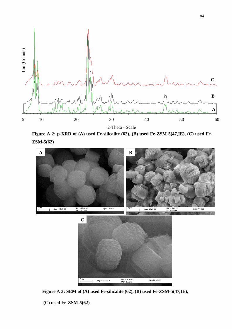
84
2-Theta - Scale
5 10 20 30 40 50 60
Lin
(C
ounts
)
C
B
A
Figure A 2: p-XRD of (A) used Fe-silicalite (62), (B) used Fe-ZSM-5(47,IE), (C) used Fe-
ZSM-5(62)
Figure A 3: SEM of (A) used Fe-silicalite (62), (B) used Fe-ZSM-5(47,IE),
(C) used Fe-ZSM-5(62)
A B
C

85
0
0.5
1
1.5
2
2.5
Cycle 1 Cycle 2 Cycle 3
% C
on
ver
sion
Catalyst cycle
2.05 1.8 1.7
Figure A 4: SEM of (A) used Fe-silicalite (62), (B) used Fe-ZSM-5(47,IE),
(C) used Fe-ZSM-5(62)
A B
C
Figure A 5: Conversion data after three reaction cycles using Fe-ZSM-5(47,IE)
at optimum conditions

86
0%
5%
10%
15%
20%
25%
30%
4-one 3-one 2-one 4-ol 3-ol al 2-ol 1-ol
Pro
du
ct s
elec
tivit
y/
%
Product distribution
1.6Fe-Silicalite 0.9Fe0.8V-silicalite 0.3Fe1.3V-silicalite 1.8V-Silicalite
0%
5%
10%
15%
20%
25%
30%
35%
4-one 3-one 2-one 4-ol 3-ol al 2-ol 1-ol
Pro
du
ct s
elec
tivit
y/
%
Product distribution
Recycled Fe-ZSM-5(47,IE) Recycled Fe-silicalite(62)Recycled 0.9Fe0.8V-silicalite Recycled Fe-ZSM-5(62)
0%
5%
10%
15%
20%
25%
30%
4-one 3-one 2-one 4-ol 3-ol al 2-ol 1-olPro
du
ct s
elec
tiv
ity
/ %
Product distribution for Fe-ZSM-5(62)
Figure A 6: Product distribution of n-octane oxidation over different silicalite catalysts
Figure A 7: Product distribution of n-octane oxidation over different recycled catalysts
Figure A 8: Product distribution of n-octane oxidation over Fe-ZSM-5(62)

87
Catalysts octanone(s)/octanol(s) ratio
1.6-Fe-ZSM-5(IE) 1.1
1.1Fe0.8V-ZSM-5(IE) 1.4
0.4Fe1.2V-ZSM-5(IE) 1.2
1.7V-ZSM-5(IE) 1.7
1.6Fe-silicalite 1.3
0.9Fe0.8V-silicalite 1.5
0.3Fe1.3V-silicalite 1.4
1.8V-silicalite 1.1
Catalysts BET (m2/g) Pore Volume (cm
3/g) Pore Size (nm)
Na- ZSM-5 326.7 0.18 20.1
Na-silicalite 383.0 0.13 24.9
Table A 1: octanone(s)/octanol(s) ratio over different catalysts at iso-conversion
of 2.7 % for ZSM-5 and 1.7 % for silicalite catalysts.
Table A 2: Surface properties of the ZSM-5 and silicalites catalysts.