Embed Size (px)
Citation preview
File: {CUP_REV}Chapman-0521832926/Revises/0521832926c03.3dCreator: / Date/Time: 17.10.2006/5:48pm Page: 71/94
3
Terrestrial analogs to the calderas of the Tharsisvolcanoes on Mars
Peter J. Mouginis-Mark, Andrew J. L. Harris and Scott K. RowlandHawaii Institute of Geophysics and Planetology,
University of Hawaii at Manoa.
3.1 Introduction
The structure and morphology of Martian calderas have been well studied
through analysis of the Viking Orbiter images (e.g., Mouginis-Mark, 1981;
Wood, 1984; Mouginis-Mark and Robinson, 1992; Crumpler et al., 1996),
and provide important information on the evolution and eruptive styles
of the parent volcanoes. Using Viking data it has been possible, for numerous
calderas, to define the sequence of collapse events, identify locations
of intra-caldera activity, and recognize post-eruption deformation for several
calderas. Inferences about the geometry and depth of the magma chamber
and intrusions beneath the summit of the volcano can also be made from
image data (Zuber and Mouginis-Mark, 1992; Scott and Wilson, 1999). In at
least one case, Olympus Mons, analysis of compressional and extensional
features indicates that, when active, the magma chamber was located within
the edifice (i.e., at an elevation above the surrounding terrain). The summit
areas of Olympus and Ascraeus Montes provide evidence of a dynamic
history, with deep calderas showing signs of having been full at one time
to the point that lava flows spilled over the caldera rim (Mouginis-Mark,
1981). Similarly, shallow calderas contain evidence that they were once deeper
(e.g., the western caldera of Alba Patera; Crumpler et al., 1996). Some
of the best evidence for circumferential vents on Mars can be found on
Pavonis Mons, where several sinuous rilles can be identified that must have
originated from vents close to the rim (Zimbelman and Edgett, 1992).
Mouginis-Mark and Rowland (2001) reviewed the geomorphic information
for Martian calderas that can be determined from the Viking Orbiter data.
The Geology of Mars: Evidence from Earth-Based Analogs, ed. Mary Chapman. Published by CambridgeUniversity Press. � Cambridge University Press 2007.
71
File: {CUP_REV}Chapman-0521832926/Revises/0521832926c03.3dCreator: / Date/Time: 17.10.2006/5:48pm Page: 71/94
They made certain predictions about what might be learnt from analysis of
higher spatial resolution data provided by the Mars Orbiter Camera (MOC)
and the visible camera that is part of the Thermal Emission Imaging
System (THEMIS), as well as the analysis of digital topographic data from
the Mars Orbiter Laser Altimeter (MOLA). MOC images have a spatial
resolution of �1.5 to 6.0 m/pixel, and THEMIS visible wavelength images
have a resolution of 19 m/pixel; in both instances, this coverage is much
better than the 40�200m/pixel data that were typically obtained by the Viking
Orbiters. As this chapter will show, these data do indeed provide a wealth of
new information on the structure and evolution of calderas on Mars, and
importantly this new information makes direct comparison between calderas
on Earth andMars more instructive. Nowhere is this opportunity for utilizing
terrestrial analogs greater than with the four giant shield volcanoes in the
Tharsis region of Mars: Olympus, Arsia, Pavonis, and Ascraeus Montes
(Figure 3.1). This chapter concentrates on these four volcanoes and identifies
clear differences in the subsidence and/or infilling history of each. For each
key caldera feature we have identified a terrestrial analog. Coupled with field
observations of these analogs, MOC, MOLA, and THEMIS observations
provide new insights into the subsurface structure and magma supply rate
for each Martian volcano.
This comparative study also underscores the importance of continued study
of equivalent caldera features and processes on Earth. Although only one
large-scale caldera collapse event at a basaltic shield has occurred in the
historic record (the 1968 collapse of Fernandina caldera, Galapagos; Simkin
and Howard, 1970), fieldwork on terrestrial calderas continues to provide
insight into these dynamic features that can be applied to comparable features
on Mars. Few of the terrestrial examples have been studied with the goal of
furthering an understanding of their planetary analogs, thereby opening
the possibility of future productive analysis of calderas on basaltic volcanoes
on Earth.
In each instance in the following discussion, attention is drawn to how
particular terrestrial analogs are instructive for understanding the following
attributes of Martian calderas:
(1) The occurrence and distribution of intra-caldera slumps and avalanches;
(2) The variability in the location and size of multiple collapse centers;
(3) The occurrence of intra-caldera benches;
(4) Broad-scale sagging of the summit;
(5) The magnitude and variability in the tilting of caldera floors;
(6) The location and magnitude of intra-caldera eruptions.
72 Terrestrial analogs to the calderas of the Tharsis volcanoes on Mars
File: {CUP_REV}Chapman-0521832926/Revises/0521832926c03.3dCreator: / Date/Time: 17.10.2006/5:48pm Page: 71/94
This chapter concludes with a more detailed description of the caldera at
Masaya volcano, Nicaragua. Here, multiple collapse events and ease of access
allow for detailed study of numerous collapse and infilling events and the ways
in which they interact. Many features at Masaya assist in understanding the
dynamics of Martian caldera floors.
3.2 Observations of deformation and infilling on the Tharsis shields
3.2.1 Arsia Mons
The interior of the Arsia Mons caldera (Figure 3.2a) is nearly horizontal,
varying in elevation by only �300 m across the 110 km diameter caldera.
First recognized in low-Sun angle Viking images (Carr et al., 1977; Crumpler
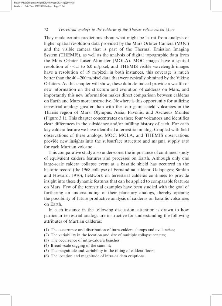
Figure 3.1. Location map for the Tharsis Montes. Image is a shaded reliefversion of the 128th degree MOLA digital elevation model. Field of viewextends from 20�S to 50�N, and 210 to 270�E. The main volcanoes areindicated (‘‘O.M.’’ is Olympus Mons, ‘‘Ar.M.’’ is Arsia Mons, ‘‘P.M.’’ isPavonis Mons, ‘‘As.M.’’ is Ascraeus Mons, and ‘‘A.P.’’ is Alba Patera).
73Observations of deformation and infilling on the Tharsis shields
File: {CUP_REV}Chapman-0521832926/Revises/0521832926c03.3dCreator: / Date/Time: 17.10.2006/5:48pm Page: 71/94
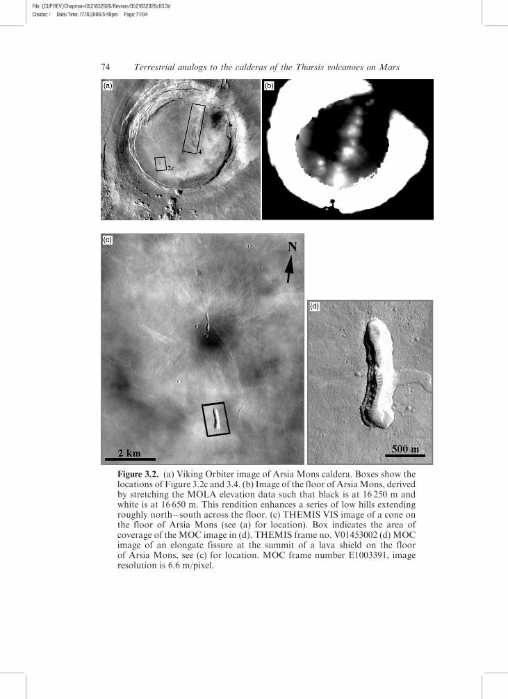
Figure 3.2. (a) Viking Orbiter image of Arsia Mons caldera. Boxes show thelocations of Figure 3.2c and 3.4. (b) Image of the floor of ArsiaMons, derivedby stretching the MOLA elevation data such that black is at 16 250 m andwhite is at 16 650 m. This rendition enhances a series of low hills extendingroughly north�south across the floor. (c) THEMIS VIS image of a cone onthe floor of Arsia Mons (see (a) for location). Box indicates the area ofcoverage of the MOC image in (d). THEMIS frame no. V01453002 (d) MOCimage of an elongate fissure at the summit of a lava shield on the floorof Arsia Mons, see (c) for location. MOC frame number E1003391, imageresolution is 6.6 m/pixel.
74 Terrestrial analogs to the calderas of the Tharsis volcanoes on Mars
File: {CUP_REV}Chapman-0521832926/Revises/0521832926c03.3dCreator: / Date/Time: 17.10.2006/5:48pm Page: 71/94
andAubele, 1978), there is a series of low hills aligned in a general NNE�SSW
orientation across the caldera floor (Figure 3.2b). Similar intra-caldera hills
have not been found at any of the other large Martian volcanoes with the
possible exception of Ulysses Patera (Plescia, 1994). MOLA data show that
these hills are shield-like in morphology, with heights of �200 m and basal
diameters of �20 km, yielding average flank slopes of well less than a tenth
of a degree. THEMIS visible images confirm the interpretation of Carr et al.
(1977) that these hills are small lava shields. Each has an elongate crater at the
summit and a subtle radial texture consisting of lava flows, most of which
are <250 m wide (Figure 3.2c). MOC data reveal layers within the summit
craters (Figure 3.2d). Using Viking Orbiter images, Mouginis-Mark (1981)
identified a few individual lava flows on the NW inner wall and floor of the
caldera. Subsequent analysis of MOC and THEMIS data show that flow
margins are only visible on the floor immediately surrounding the lava shields,
no other flows are visible either in the limited coverage provided by MOC,
or the more extensive THEMIS coverage.
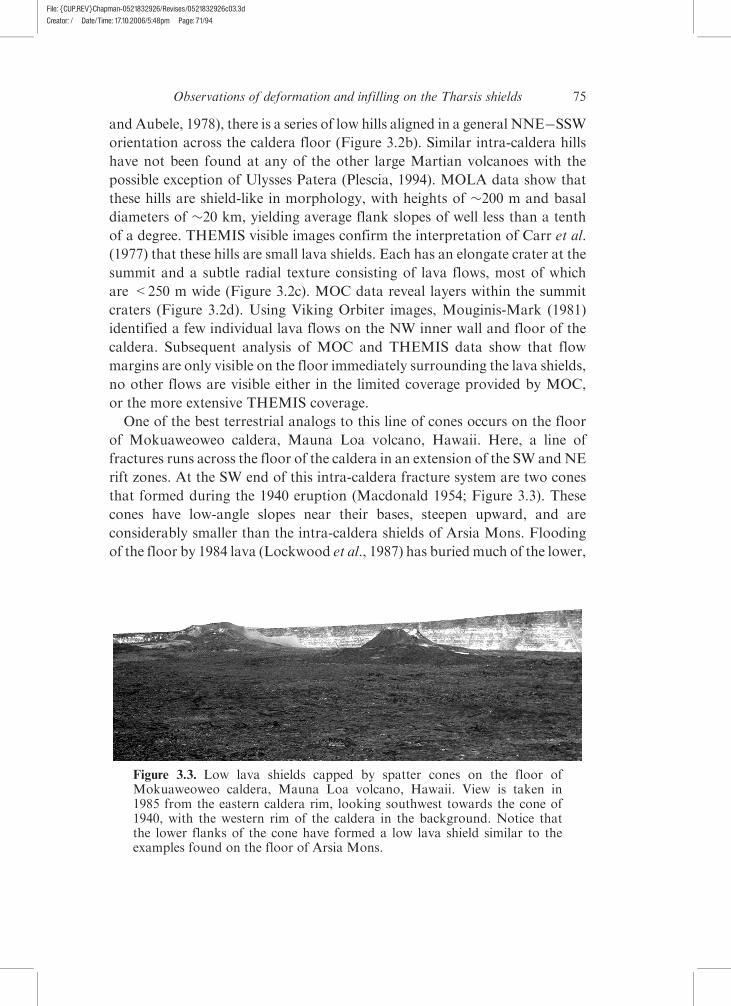
One of the best terrestrial analogs to this line of cones occurs on the floor
of Mokuaweoweo caldera, Mauna Loa volcano, Hawaii. Here, a line of
fractures runs across the floor of the caldera in an extension of the SW andNE
rift zones. At the SW end of this intra-caldera fracture system are two cones
that formed during the 1940 eruption (Macdonald 1954; Figure 3.3). These
cones have low-angle slopes near their bases, steepen upward, and are
considerably smaller than the intra-caldera shields of Arsia Mons. Flooding
of the floor by 1984 lava (Lockwood et al., 1987) has buried much of the lower,
Figure 3.3. Low lava shields capped by spatter cones on the floor ofMokuaweoweo caldera, Mauna Loa volcano, Hawaii. View is taken in1985 from the eastern caldera rim, looking southwest towards the cone of1940, with the western rim of the caldera in the background. Notice thatthe lower flanks of the cone have formed a low lava shield similar to theexamples found on the floor of Arsia Mons.
75Observations of deformation and infilling on the Tharsis shields
File: {CUP_REV}Chapman-0521832926/Revises/0521832926c03.3dCreator: / Date/Time: 17.10.2006/5:48pm Page: 71/94
gentler slopes of these cones, accentuating their overall steepness and making
them less similar in appearance to the Arsia Mons cones. However, it is
evident that the base of each 1940 cone is actually a low lava shield and
the upper (steeper) portion is a cap of spatter. Unlike the Arsia Mons cones,
the 1940 cones are fairly symmetric, but like Arsia Mons the 1940 cones
lie along a fundamental structural lineament of the volcano. THEMIS
data of the Arsia Mons caldera (Figures 3.2a and 3.4) show that the cones
lie along a structural trend that includes a breach in the SW caldera wall
through which voluminous lavas have issued and produced a lava fan on
the SW flanks (Crumpler et al., 1996) and a set of deep pits/fractures on
the NE flank that are associated with a similar lava fan. Additionally, this
generally SW�NE trend is the same as that along which Arsia, Pavonis,
and Ascraeus Montes are distributed. It is interesting to note that although
the intra-caldera Arsia Mons lava shields are located along this fundamental
trend, the elongate summit craters are in an en echelon orientation, showing
vergence to the east.
3.2.2 Pavonis Mons
The summit of Pavonis Mons contains an obvious, deep, roughly circular,
45�50 km diameter caldera, termed the ‘‘small caldera’’ by Crumpler et al.
(1996). Inspection of MOLA topography shows that the northern wall of
the small caldera is �2700 m high, and the southern wall is �4600 m high.
The floor of the small caldera is remarkably featureless and horizontal, with
a change in elevation across the floor of only �40�50 m. Crumpler et al.
(1996) interpreted the lack of features on the small caldera floor to indicate
either a young age or mantling by dust. The walls of the small caldera are
bimodal in the sense that the western wall is characterized by numerous
slump blocks stepping from the western rim to the floor whereas the eastern
wall is essentially a single drop. Crumpler et al. (1996) interpreted the western
slumps as terraces but MOLA topography indicates that their top surfaces are
not horizontal. These slumps appear to be the result of post-caldera
mass-wasting and are very similar to those found on the northern wall of
the Fernandina caldera (Galapagos; Rowland and Munro, 1992).
Additionally, a larger but shallower collapse feature, the large caldera, can
be identified in Viking images, lying immediately to the north of the small
caldera (Figure 3.5). The large caldera is also roughly circular with a diameter
of 80�100 km. Unlike the deeper, small caldera it is much more structurally
complex. The west, north, and most of the east boundaries of this larger
collapse structure have a ridge-like morphology, down-dropped not only
76 Terrestrial analogs to the calderas of the Tharsis volcanoes on Mars
File: {CUP_REV}Chapman-0521832926/Revises/0521832926c03.3dCreator: / Date/Time: 17.10.2006/5:48pm Page: 71/94
inward towards the center but outward and downslope as well. To the
southwest the margin is truncated by the small caldera. To the south the
obvious ridge-like margin becomes indistinct and Crumpler et al. (1996)
interpreted this to be due to burial by post-large-depression lava flows.
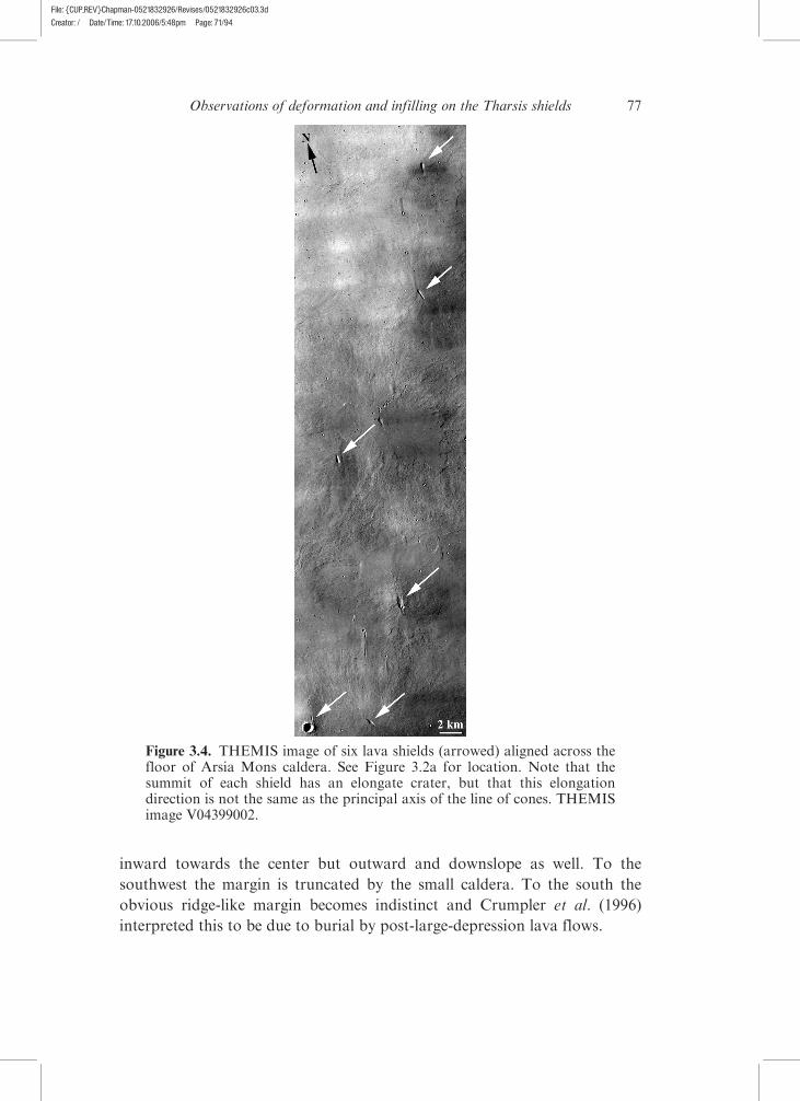
Figure 3.4. THEMIS image of six lava shields (arrowed) aligned across thefloor of Arsia Mons caldera. See Figure 3.2a for location. Note that thesummit of each shield has an elongate crater, but that this elongationdirection is not the same as the principal axis of the line of cones. THEMISimage V04399002.
77Observations of deformation and infilling on the Tharsis shields
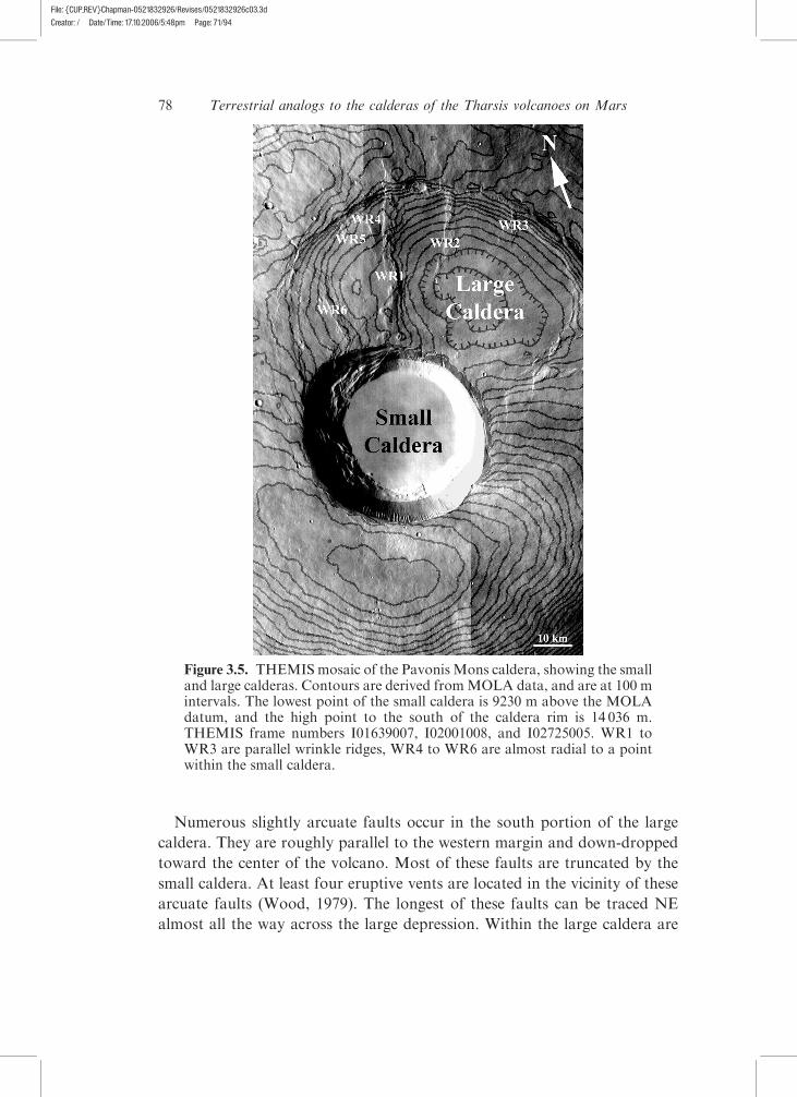
File: {CUP_REV}Chapman-0521832926/Revises/0521832926c03.3dCreator: / Date/Time: 17.10.2006/5:48pm Page: 71/94
Numerous slightly arcuate faults occur in the south portion of the large
caldera. They are roughly parallel to the western margin and down-dropped
toward the center of the volcano. Most of these faults are truncated by the
small caldera. At least four eruptive vents are located in the vicinity of these
arcuate faults (Wood, 1979). The longest of these faults can be traced NE
almost all the way across the large depression. Within the large caldera are
Figure 3.5. THEMISmosaic of the Pavonis Mons caldera, showing the smalland large calderas. Contours are derived fromMOLA data, and are at 100 mintervals. The lowest point of the small caldera is 9230 m above the MOLAdatum, and the high point to the south of the caldera rim is 14 036 m.THEMIS frame numbers I01639007, I02001008, and I02725005. WR1 toWR3 are parallel wrinkle ridges, WR4 to WR6 are almost radial to a pointwithin the small caldera.
78 Terrestrial analogs to the calderas of the Tharsis volcanoes on Mars
File: {CUP_REV}Chapman-0521832926/Revises/0521832926c03.3dCreator: / Date/Time: 17.10.2006/5:48pm Page: 71/94
three roughly parallel, NW-trending, wrinkle ridges. The longest arcuate
fault cuts across the westernmost of three roughly parallel wrinkle ridges
(see below) and appears to truncate the other two although it does not
extend obviously to the easternmost one.
At least six wrinkle ridges can be identified within and just outside the
large caldera (Figure 3.5). These were interpreted as radial structures by
Crumpler et al. (1996); however, as noted above, three of them are parallel to
one another and therefore cannot be radial. A couple of the other wrinkle
ridges do have an orientation radial to a point in the NE part of the small
caldera but if all of them are considered together they are not in a radial
orientation. Instead, the three parallel wrinkle ridges lie along the same
fundamental NW�SE structural trend seen at Arsia Mons and along which
Arsia, Pavonis, and Ascraeus Montes are located. Two more of the wrinkle
ridges are roughly parallel to this trend, leaving only one of the six that is
not. That these wrinkle ridges are cut by intra-caldera faults and possibly also
buried by lava flows indicates that they pre-date formation of the large
caldera. Additionally, at least one and perhaps a second of the wrinkle ridges
extends beyond the NE margin of the large caldera, making it unlikely that
it is associated with intra-caldera compression. The small caldera truncates
the large caldera’s outer margin, the arcuate faults, and the wrinkle ridges,
clearly making its formation the most recent large-scale tectonic event.
Neither the large nor the small caldera rim is at a constant elevation. Instead
the highest elevation of the rim occurs SW of the small caldera. MOLA topo-
graphy indicates that this southern part of the summit is the highest part of
the volcano (�14 050 m), supporting the idea that this is an area where recent
construction occurred. Such an offset was also noted at Olympus Mons
(Mouginis-Mark and Robinson, 1992), and Walker (1988) observed that
both Mauna Loa and Kilauea show a similar relationship. In both of these
Hawaiian examples the calderas are offset to the SE from the topographic
highest points on their respective volcanoes. This offset relationship may
develop for any of three possible reasons. First it could indicate that con-
struction by lava flows and pyroclastics was not favored directly above the
magma chamber, and instead non-vertical eruptive dikes were most common.
Second it might indicate migration of the magma chamber from an originally
more central location. Finally, consider a spherical magma chamber centered
within a right circular cone. The closest distance from the magma chamber
wall to the surface (and hence the thinnest carapace of solid rock) will not
be directly upwards but instead at an angle towards the side. It may be that
when collapse stresses are accumulating around an evacuated or partially
evacuated magma chamber it is these locations that are most likely to collapse.
79Observations of deformation and infilling on the Tharsis shields
File: {CUP_REV}Chapman-0521832926/Revises/0521832926c03.3dCreator: / Date/Time: 17.10.2006/5:48pm Page: 71/94
The large caldera at Pavonis Mons shows clear evidence of centripetal
sagging because its surface slopes inward. In fact, the center of the shallow
caldera is almost a kilometer (�840 m) lower than the outer edge of the floor.
This sagging has been noted in the exhumed Koolau caldera (Hawaii) by
Walker (1988) and attributed to the gravitational sinking of a cumulate
pile that develops within the core of the volcano.
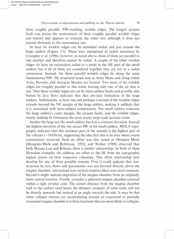
3.2.3 Ascraeus Mons
The summit caldera complex of Ascraeus Mons consists of four large,
coalesced collapse structures (Figure 3.6a), the deepest and most central of
which is the most recent (Mouginis-Mark, 1981; Crumpler et al., 1996).
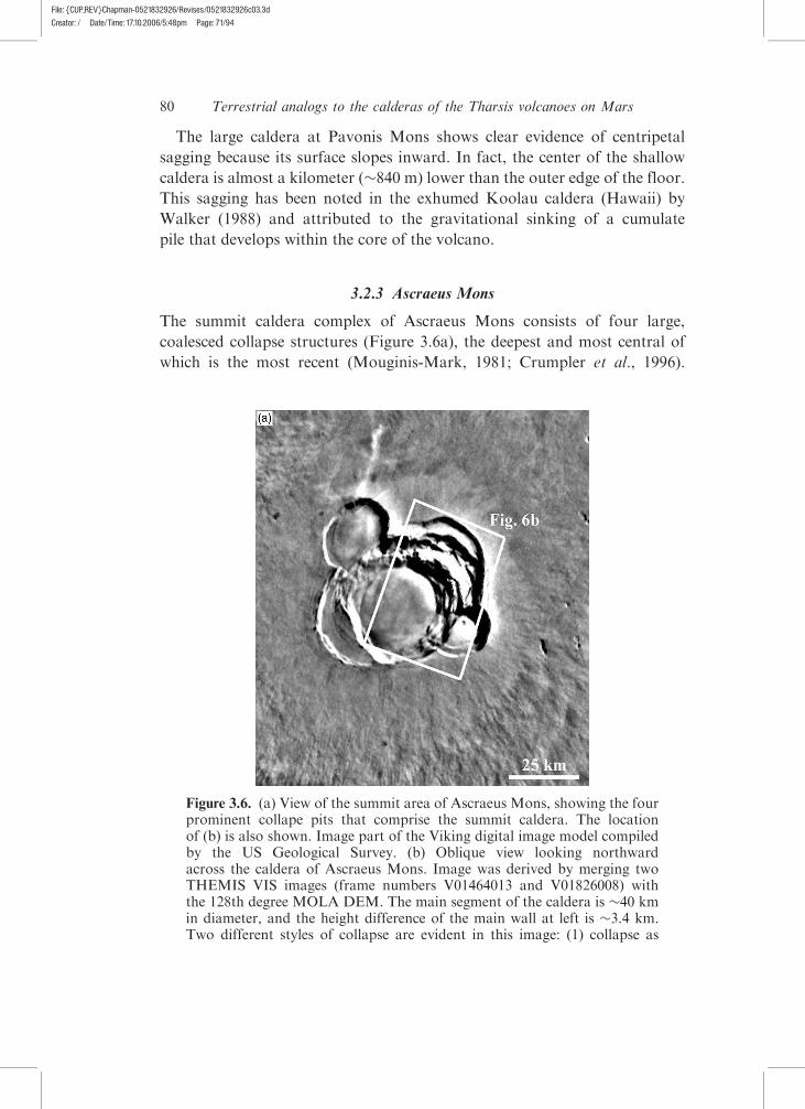
Figure 3.6. (a) View of the summit area of Ascraeus Mons, showing the fourprominent collape pits that comprise the summit caldera. The locationof (b) is also shown. Image part of the Viking digital image model compiledby the US Geological Survey. (b) Oblique view looking northwardacross the caldera of Ascraeus Mons. Image was derived by merging twoTHEMIS VIS images (frame numbers V01464013 and V01826008) withthe 128th degree MOLA DEM. The main segment of the caldera is �40 kmin diameter, and the height difference of the main wall at left is �3.4 km.Two different styles of collapse are evident in this image: (1) collapse as
80 Terrestrial analogs to the calderas of the Tharsis volcanoes on Mars
File: {CUP_REV}Chapman-0521832926/Revises/0521832926c03.3dCreator: / Date/Time: 17.10.2006/5:48pm Page: 71/94
The four older calderas are located roughly to the NE, SE, SW, and NW of
the deepest central caldera. MOLA topography indicates that the floors of all
four of these older calderas are at different elevations, indicating either
that they were never continuous or that if they were, their order of most
recent collapse is in an order from currently shallowest to currently deepest
(NW, NE, SW, SE). The caldera of Karthala (Grand Comoros Islands)
is similarly complex and Mouginis-Mark and Rowland (2001) presented
an order of collapse feature formation based on a similar comparison of
floor depth.
As noted above the central caldera is the deepest and most recent, based
on the fact that it truncates the four more outer calderas. This central caldera
is �24 km across and �3.4 km deep, and presents evidence of significant
postformation mass wasting, on both large and small scales. Most notably,
more than half of the NE caldera has slumped into the central caldera,
producing a series of downward-stepping blocks separated by normal
Figure 3.6. (cont.) individual pits and (2) progressive slumping as a seriesof narrow slump blocks. The large arrow indicates an area where bothprocesses have occurred, with the slumping modifying the original pit. Thelocations of the MOC data shown in Figure 3.9a and 3.9b are indicated, withsmall arrows indicating the viewing directions. Vertical exaggeration is 8�.
81Observations of deformation and infilling on the Tharsis shields
File: {CUP_REV}Chapman-0521832926/Revises/0521832926c03.3dCreator: / Date/Time: 17.10.2006/5:48pm Page: 71/94
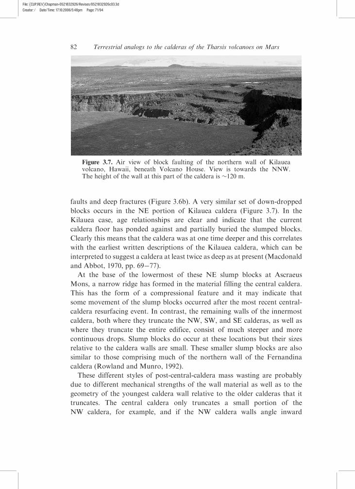
faults and deep fractures (Figure 3.6b). A very similar set of down-dropped
blocks occurs in the NE portion of Kilauea caldera (Figure 3.7). In the
Kilauea case, age relationships are clear and indicate that the current
caldera floor has ponded against and partially buried the slumped blocks.
Clearly this means that the caldera was at one time deeper and this correlates
with the earliest written descriptions of the Kilauea caldera, which can be
interpreted to suggest a caldera at least twice as deep as at present (Macdonald
and Abbot, 1970, pp. 69�77).
At the base of the lowermost of these NE slump blocks at Ascraeus
Mons, a narrow ridge has formed in the material filling the central caldera.
This has the form of a compressional feature and it may indicate that
some movement of the slump blocks occurred after the most recent central-
caldera resurfacing event. In contrast, the remaining walls of the innermost
caldera, both where they truncate the NW, SW, and SE calderas, as well as
where they truncate the entire edifice, consist of much steeper and more
continuous drops. Slump blocks do occur at these locations but their sizes
relative to the caldera walls are small. These smaller slump blocks are also
similar to those comprising much of the northern wall of the Fernandina
caldera (Rowland and Munro, 1992).
These different styles of post-central-caldera mass wasting are probably
due to different mechanical strengths of the wall material as well as to the
geometry of the youngest caldera wall relative to the older calderas that it
truncates. The central caldera only truncates a small portion of the
NW caldera, for example, and if the NW caldera walls angle inward
Figure 3.7. Air view of block faulting of the northern wall of Kilaueavolcano, Hawaii, beneath Volcano House. View is towards the NNW.The height of the wall at this part of the caldera is �120 m.
82 Terrestrial analogs to the calderas of the Tharsis volcanoes on Mars
File: {CUP_REV}Chapman-0521832926/Revises/0521832926c03.3dCreator: / Date/Time: 17.10.2006/5:48pm Page: 71/94
(which is likely) they will act against the tendency for the NW caldera
fill material to slump en masse into the central caldera. A similar argument
can be made for the SE caldera although the youngest caldera truncates
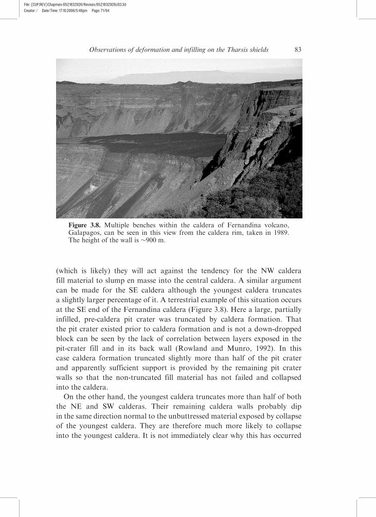
a slightly larger percentage of it. A terrestrial example of this situation occurs
at the SE end of the Fernandina caldera (Figure 3.8). Here a large, partially
infilled, pre-caldera pit crater was truncated by caldera formation. That
the pit crater existed prior to caldera formation and is not a down-dropped
block can be seen by the lack of correlation between layers exposed in the
pit-crater fill and in its back wall (Rowland and Munro, 1992). In this
case caldera formation truncated slightly more than half of the pit crater
and apparently sufficient support is provided by the remaining pit crater
walls so that the non-truncated fill material has not failed and collapsed
into the caldera.
On the other hand, the youngest caldera truncates more than half of both
the NE and SW calderas. Their remaining caldera walls probably dip
in the same direction normal to the unbuttressed material exposed by collapse
of the youngest caldera. They are therefore much more likely to collapse
into the youngest caldera. It is not immediately clear why this has occurred
Figure 3.8. Multiple benches within the caldera of Fernandina volcano,Galapagos, can be seen in this view from the caldera rim, taken in 1989.The height of the wall is �900 m.
83Observations of deformation and infilling on the Tharsis shields
File: {CUP_REV}Chapman-0521832926/Revises/0521832926c03.3dCreator: / Date/Time: 17.10.2006/5:48pm Page: 71/94
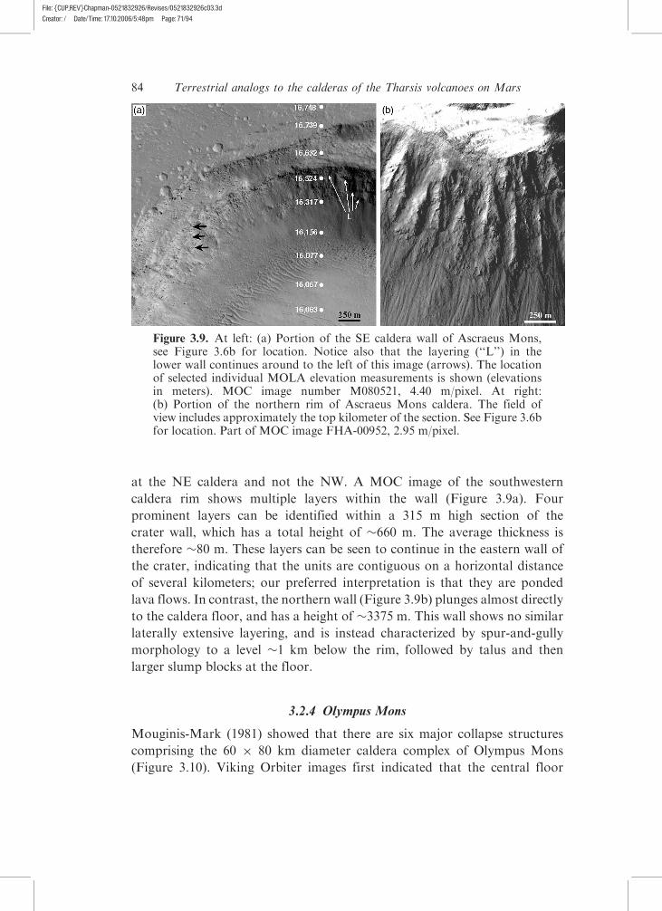
at the NE caldera and not the NW. A MOC image of the southwestern
caldera rim shows multiple layers within the wall (Figure 3.9a). Four
prominent layers can be identified within a 315 m high section of the
crater wall, which has a total height of �660 m. The average thickness is
therefore �80 m. These layers can be seen to continue in the eastern wall of
the crater, indicating that the units are contiguous on a horizontal distance
of several kilometers; our preferred interpretation is that they are ponded
lava flows. In contrast, the northern wall (Figure 3.9b) plunges almost directly
to the caldera floor, and has a height of �3375 m. This wall shows no similar
laterally extensive layering, and is instead characterized by spur-and-gully
morphology to a level �1 km below the rim, followed by talus and then
larger slump blocks at the floor.
3.2.4 Olympus Mons
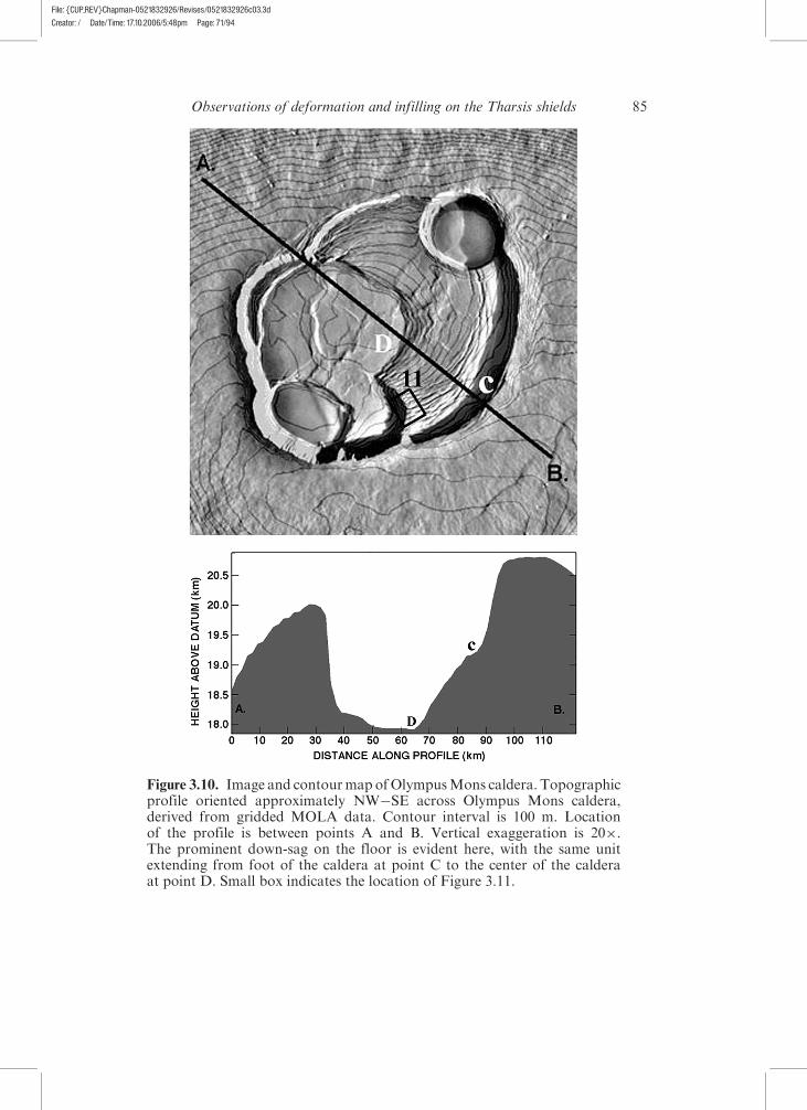
Mouginis-Mark (1981) showed that there are six major collapse structures
comprising the 60 � 80 km diameter caldera complex of Olympus Mons
(Figure 3.10). Viking Orbiter images first indicated that the central floor
Figure 3.9. At left: (a) Portion of the SE caldera wall of Ascraeus Mons,see Figure 3.6b for location. Notice also that the layering (‘‘L’’) in thelower wall continues around to the left of this image (arrows). The locationof selected individual MOLA elevation measurements is shown (elevationsin meters). MOC image number M080521, 4.40 m/pixel. At right:(b) Portion of the northern rim of Ascraeus Mons caldera. The field ofview includes approximately the top kilometer of the section. See Figure 3.6bfor location. Part of MOC image FHA-00952, 2.95 m/pixel.
84 Terrestrial analogs to the calderas of the Tharsis volcanoes on Mars
File: {CUP_REV}Chapman-0521832926/Revises/0521832926c03.3dCreator: / Date/Time: 17.10.2006/5:48pm Page: 71/94
Figure 3.10. Image and contourmap ofOlympusMons caldera. Topographicprofile oriented approximately NW�SE across Olympus Mons caldera,derived from gridded MOLA data. Contour interval is 100 m. Locationof the profile is between points A and B. Vertical exaggeration is 20�.The prominent down-sag on the floor is evident here, with the same unitextending from foot of the caldera at point C to the center of the calderaat point D. Small box indicates the location of Figure 3.11.
85Observations of deformation and infilling on the Tharsis shields
File: {CUP_REV}Chapman-0521832926/Revises/0521832926c03.3dCreator: / Date/Time: 17.10.2006/5:48pm Page: 71/94
of Olympus Mons’ caldera has subsided by more that 1 km with respect to
the perimeter of the caldera floor (Mouginis-Mark and Robinson, 1992;
Figure 3.10). As at Pavonis Mons, this sagging is analogous to that
documented at Koolau by Walker (1988). The largest and oldest of the
segments appears to have formed as a single large lava lake (Crater #1
using the nomenclature of Mouginis-Mark, 1981). This part of the floor
is heavily fractured by numerous circumferential graben. A MOLA
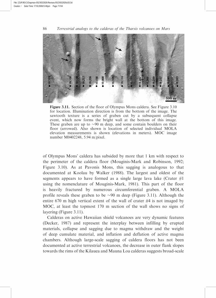
profile reveals these graben to be �90 m deep (Figure 3.11). Although the
entire 670 m high vertical extent of the wall of crater #4 is not imaged by
MOC, at least the topmost 170 m section of the wall shows no signs of
layering (Figure 3.11).
Calderas on active Hawaiian shield volcanoes are very dynamic features
(Decker, 1987) and represent the interplay between infilling by erupted
materials, collapse and sagging due to magma withdraw and the weight
of deep cumulate material, and inflation and deflation of active magma
chambers. Although large-scale sagging of caldera floors has not been
documented at active terrestrial volcanoes, the decrease in outer flank slopes
towards the rims of the Kilauea andMauna Loa calderas suggests broad-scale
Figure 3.11. Section of the floor of Olympus Mons caldera. See Figure 3.10for location. Illumination direction is from the bottom of the image. Thesawtooth texture is a series of graben cut by a subsequent collapseevent, which now forms the bright wall at the bottom of this image.These graben are up to �90 m deep, and some contain boulders on theirfloor (arrowed). Also shown is location of selected individual MOLAelevation measurements is shown (elevations in meters). MOC imagenumber M0402248, 5.94 m/pixel.
86 Terrestrial analogs to the calderas of the Tharsis volcanoes on Mars
File: {CUP_REV}Chapman-0521832926/Revises/0521832926c03.3dCreator: / Date/Time: 17.10.2006/5:48pm Page: 71/94
downward sagging (Rowland and Garbeil, 2000). The inward sagging
recorded in the lavas of Koolau volcano (Walker, 1988) also record this
gentle downward motion. That most active calderas do not show this behavior
in their caldera floors is almost certainly due to the regular resurfacing
that occurs.
Fortuitously, subsidence and the ability to observe the crater floor in
cross-section at Masaya volcano (Nicaragua) presents an opportunity to
study the same type of subsidence in the field. Masaya is a persistently active
basaltic volcano that comprises four main pit craters, which are named
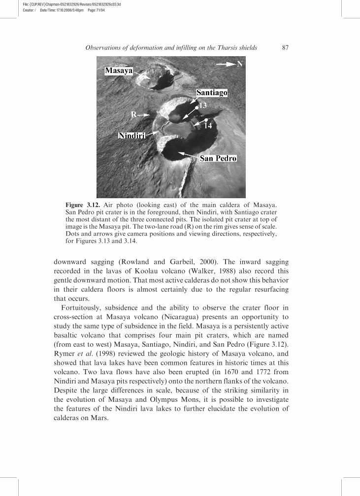
(from east to west) Masaya, Santiago, Nindiri, and San Pedro (Figure 3.12).
Rymer et al. (1998) reviewed the geologic history of Masaya volcano, and
showed that lava lakes have been common features in historic times at this
volcano. Two lava flows have also been erupted (in 1670 and 1772 from
Nindiri andMasaya pits respectively) onto the northern flanks of the volcano.
Despite the large differences in scale, because of the striking similarity in
the evolution of Masaya and Olympus Mons, it is possible to investigate
the features of the Nindiri lava lakes to further elucidate the evolution of
calderas on Mars.
Figure 3.12. Air photo (looking east) of the main caldera of Masaya.San Pedro pit crater is in the foreground, then Nindiri, with Santiago craterthe most distant of the three connected pits. The isolated pit crater at top ofimage is theMasaya pit. The two-lane road (R) on the rim gives sense of scale.Dots and arrows give camera positions and viewing directions, respectively,for Figures 3.13 and 3.14.
87Observations of deformation and infilling on the Tharsis shields
File: {CUP_REV}Chapman-0521832926/Revises/0521832926c03.3dCreator: / Date/Time: 17.10.2006/5:48pm Page: 71/94
3.3 Field investigation of terrestrial analogs: Masaya volcano, Nicaragua
There are numerous strong similarities between Masaya and the Olympus
Mons caldera. The most obvious comparison can be seen within Nindiri
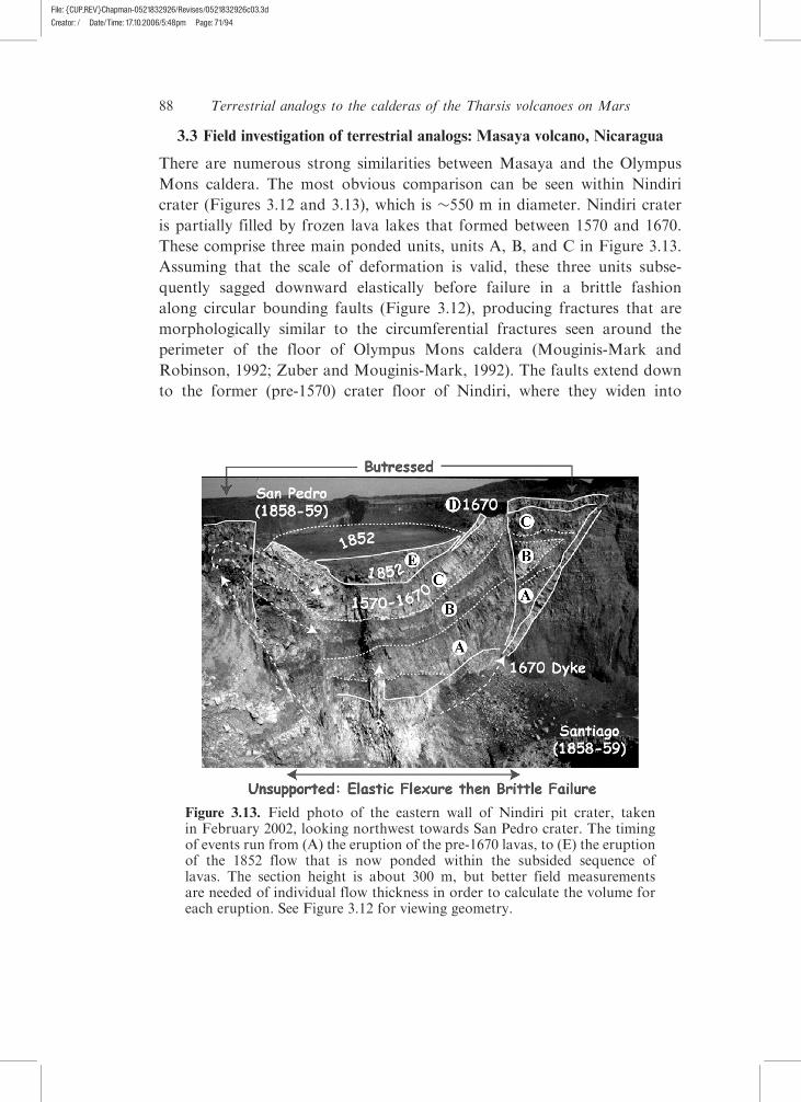
crater (Figures 3.12 and 3.13), which is �550 m in diameter. Nindiri crater
is partially filled by frozen lava lakes that formed between 1570 and 1670.
These comprise three main ponded units, units A, B, and C in Figure 3.13.
Assuming that the scale of deformation is valid, these three units subse-
quently sagged downward elastically before failure in a brittle fashion
along circular bounding faults (Figure 3.12), producing fractures that are
morphologically similar to the circumferential fractures seen around the
perimeter of the floor of Olympus Mons caldera (Mouginis-Mark and
Robinson, 1992; Zuber and Mouginis-Mark, 1992). The faults extend down
to the former (pre-1570) crater floor of Nindiri, where they widen into
Figure 3.13. Field photo of the eastern wall of Nindiri pit crater, takenin February 2002, looking northwest towards San Pedro crater. The timingof events run from (A) the eruption of the pre-1670 lavas, to (E) the eruptionof the 1852 flow that is now ponded within the subsided sequence oflavas. The section height is about 300 m, but better field measurementsare needed of individual flow thickness in order to calculate the volume foreach eruption. See Figure 3.12 for viewing geometry.
88 Terrestrial analogs to the calderas of the Tharsis volcanoes on Mars
File: {CUP_REV}Chapman-0521832926/Revises/0521832926c03.3dCreator: / Date/Time: 17.10.2006/5:48pm Page: 71/94
broad fracture zones on the north side and join with a few main faults on
the south side. The final unit in this sequence erupted into a nearly full
crater, such that lava spilled from a low point on the northern crater rim
to feed lava onto the outer flank. A more recent lava lake was subse-
quently erupted in 1852 onto the crater floor where it ponded within the
sag-structure.
San Pedro and Santiago pit craters formed subsequently, cutting the
lavas ponded in Nindiri. Fortuitously, these allow vertical sections in excess
of 300 m to be studied at the eastern and western edges of the pile. The
uppermost ponded unit, the 1852 unit, is �20 m thick and has a diameter
of 268 m. This yields a bulk volume of 1.1 � 106 m3. Ponded units A, B,
and C have a total thickness of �100 m which, with a diameter of �550 m,
gives a combined bulk volume of 7.6 � 106 m3. Units A, B, and C, as well as
the 1670 overflow unit, all appear to have sagged together. For such elastic
sagging to have occurred, it is necessary that all three units must still
have been molten at the time of deformation. This means that they must
have been erupted in close succession. At the 1963 Alae lava lake (Kilauea,
Hawaii) the 980 �C isotherm, the boundary between the brittle and molten
layers in the lake, increased in depth (d ) depending on d ¼ 0.00132pt � 0.18
(Peck, 1978). Given a �30 m thickness for the lowermost Masaya unit,
and assuming that the magma effusion rates of Masaya and Kilauea are
comparable, this places a limit of �16 years on the maximum age difference
between the oldest, lowermost, unit (A) and the youngest, uppermost, unit (C).
It is, however, likely that heating and insulation by B and C prolonged the
ductile lifetime of A.
The following sequence of events can be inferred. The three thick
lava pond units erupted over a <16 year time span. The final eruption in
this sequence (possibly intra-caldera activity) poured into a full crater
such that lava overflowed the northern rim. Withdrawal of shallow
conduit magma, contraction due to degassing, thermal contraction, or
compaction of the underlying talus at the end of this eruption sequence
caused these units to then sag and fail together. Finally, after a hiatus
of 82 years the 1852 eruption ponded in the sag-structure. Following
1852, the San Pedro and Santiago pit craters formed (Rymer et al., 1998).
These craters are 260 and 280 m deep and 358 and 494 m wide,
respectively, giving volumes of 3.6 and 5.4 � 107 m3. These volumes are
far in excess of the Nindiri lava lake volumes. Thus drainage of these voids
must also have involved flank eruptions and/or drain-back into the deeper
system.
89Field investigation of terrestrial analogs: Masaya volcano, Nicaragua
File: {CUP_REV}Chapman-0521832926/Revises/0521832926c03.3dCreator: / Date/Time: 17.10.2006/5:48pm Page: 71/94
3.4 Implications for Mars
The terrestrial features and insights presented here can be used as guides
and analogs when examining Olympus Mons, where the Martian lakes and
pit craters may have formed in a similar way. There are, however, some
drawbacks. If Nindiri crater is an analog to the summit of Olympus Mons,
extensional features should be found around the perched outer perimeter
of the crater and compressional features towards the center. Much of the
surface of each of the Nindiri lakes is buried by more recent units or tephra,
making it difficult to construct a geologic map of the 1570�1670 units and
the 1852 ponded lava flow within Nindiri. This creates problems when
trying to identify any extensional and compressional features that may have
formed due to continuing subsidence of the underlying surface. However,
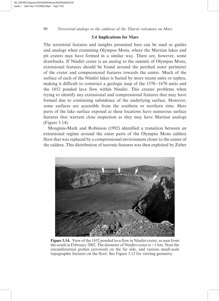
some surfaces are accessible from the southern or northern rims. Here
parts of the lake surface exposed at these locations have numerous surface
features that warrant close inspection as they may have Martian analogs
(Figure 3.14).
Mouginis-Mark and Robinson (1992) identified a transition between an
extensional regime around the outer parts of the Olympus Mons caldera
floor that was replaced by a compressional environment closer to the center of
the caldera. This distribution of tectonic features was then exploited by Zuber
Figure 3.14. View of the 1852 ponded lava flow inNindiri crater, as seen fromthe south in February 2002. The diameter of Nindiri crater is�1 km.Note thecircumferential graben (arrowed) on the far side, and various small-scaletopographic features on the floor. See Figure 3.12 for viewing geometry.
90 Terrestrial analogs to the calderas of the Tharsis volcanoes on Mars
File: {CUP_REV}Chapman-0521832926/Revises/0521832926c03.3dCreator: / Date/Time: 17.10.2006/5:48pm Page: 71/94
and Mouginis-Mark (1992), who used a finite-element model to calculate the
probable depth to the roof of the magma chamber at the time of subsidence.
Zuber and Mouginis-Mark (1992) calculated that the magma chamber roof
was �16 km beneath the floor of the solidified lava lake, placing the
magma chamber within the 20 km high volcanic edifice. The cooling histories
of terrestrial and Martian lava lakes may be different, due at least to the
absence of percolating rainwater on Mars. Even if the deep interior of lava
ponds on both planets is liquid for the same time, some of the exterior units of
terrestrial examples should be much colder for a given time and, therefore,
should have failed more easily in a brittle fashion. Brittle deformation may
thus take longer to initiate on Mars. Such detailed comparisons await future
modeling efforts.
It is also important to understand the relative timing between different
collapse events on Mars, because they are probably indicators of the magma
production rate, and hence the total age of the volcano (Wilson et al., 2001).
Given that we have evidence for elastic failure of the Olympus Mons floor, we
can suggest that the crater floor deformed while the lake was still mostly
molten, as at Nindiri. Although it is highly likely that the cooling conditions
of lava lakes on Mars were different from those on Earth, it is possible that
the subsidence took place only a few years after the lava lake was formed
and was thus at a high enough temperature to allow elastic deformation.
Brittle deformation, however, is more likely to imply a longer time period
between lava lake emplacement and collapse. The extreme case, as discussed
by Wilson et al. (2001) is that the magma chamber freezes between events so
that a new cycle of magma chamber formation, lava eruption, and pit crater
collapse has to take place.
Some volumetric and thermal constraints can also be placed on the
sequence of events. As at Masaya, by calculating the time it takes for a lake
of a given thickness to completely cool below the brittle�ductile transition,
the maximum time can be calculated during which plastic deformation can
occur (i.e., plastic deformation could only occur while the lake core was
still partially molten). This time estimate is relevant to other Martian lava
lakes that underwent plastic deformation, which should be recognized as
bowl-shaped surfaces in theMOLA elevationmeasurements. For instance, the
caldera floor of Ascraeus Mons reveals several thinner ponded lava flows
(Figure 3.9) compared to OlympusMons (Figure 3.11). Five prominent layers
can be identified within a 315 m high section of the wall of the Ascraeus Mons
crater (Figure 3.9). This implies an average thickness of the ponded lavas
of �63 m. Given the Alae relationship of Peck (1978) this thickness would
take �70 years to freeze. Reconstructing an original diameter of �20 km for
91Implications for Mars
File: {CUP_REV}Chapman-0521832926/Revises/0521832926c03.3dCreator: / Date/Time: 17.10.2006/5:48pm Page: 71/94
this crater (number 3 of Mouginis-Mark, 1981) implies an average volume
for each ponded layer of �19.8 km3. Using the same hypothetical dimensions
for an equivalent lava flow on the flanks (i.e., 50 m thick and 10 km wide)
as Olympus Mons would suggest that a single intra-caldera eruption of
Ascraeus Mons might have produced a flow �40 km long, which is typical
of lava flows observed on the flanks (Zimbelman, 1985).
3.5 Conclusions
The data for the Tharsis Montes provided by MOC, THEMIS, and MOLA
present unparalleled new opportunities for the identification of different
stages in the evolution ofMartian calderas. Fieldwork on terrestrial volcanoes
also points the direction for further studies. A key component of the terrestrial
studies is that they provide a temporal view of the way that calderas evolve,
which no doubt has been an important factor in the development of sag
features at both Olympus and Pavonis Montes. By virtue of the frequent
eruptions at Kilauea, Fernandina, Masaya, and Mauna Loa, it is possible to
better understand which landforms can form rapidly (such as a caldera
collapse) or the longer-term subsidence of the caldera floor. This current
survey using THEMIS and MOC images is inevitably limited to areas where
image data have been obtained, and where the lighting geometry allows
the identification of structures. Furthermore, because image data are still
being acquired through at least the spring of 2004, additional scenes not
included in this study will become available. An important aspect of any future
study of planetary calderas would be an attempt to identify the three-
dimensional extent of some of the units identified here, particularly those
revealed in the walls of the Olympus Mons and Ascraeus Mons calderas.
Acknowledgments
The NASA Mars Data Analysis Program supported this work under grant
NAG5-9576. We thank Laszlo Keszthelyi and Jim Zimbelman for helpful
reviews. This is Hawaii Institute of Geophysics and Planetology PaperNo. xxx
and SOEST Publication No. yyy.
References
Carr, M.H., Greeley, R., Blasius, K.R., Guest, J. E., and Murray, J. B. (1977).Some Martian volcanic features as viewed from the Viking Orbiters. Journal ofGeophysical Research, 82, 3985�4015.
92 Terrestrial analogs to the calderas of the Tharsis volcanoes on Mars
File: {CUP_REV}Chapman-0521832926/Revises/0521832926c03.3dCreator: / Date/Time: 17.10.2006/5:48pm Page: 71/94
Crumpler, L. S. and Aubele, J. C. (1978). Structural evolution of Arsia Mons, PavonisMons, and Ascraeus Mons: Tharsis region of Mars. Icarus, 34, 496�511.
Crumpler, L. S., Head, J.W., and Aubele, J. C. (1996). Calderas on Mars:characteristics, structure, and associated flank deformation. In VolcanoInstability on Earth & Other Planets, ed. W. J. McGuire, A. P. Jones, andJ. Neuberg, Geological Society Special Publication, 110., Geological Societyof London, pp. 307�48.
Decker, R.W. (1987). Dynamics of Hawaiian volcanoes: an overview. In Volcanismin Hawaii, ed. R.W. Decker, T. L. Wright, and P.H. Stauffer, US GeologicalSurvey Professional Paper 1350, pp. 997�1018.
Lockwood, J. P., Dvorak, J. J., English, T. T. et al. (1987). Mauna Loa 1974�1984:a decade of intrusive and extrusive activity. In Volcanism in Hawaii, ed.R.W. Decker, T. L. Wright, and P.H. Stauffer, US Geological SurveyProfessional Paper 1350, pp. 537�70.
Macdonald, G.A. (1954). Activity of Hawaiian volcanoes during the years 1940�50.Bulletin of Volcanology, series 2, 15, 120�79.
Macdonald, G.A. and Abbott, A. T. (1970). Volcanoes in the Sea. Honolulu:University of Hawaii Press.
Mouginis-Mark, P. J. (1981). Late-stage summit activity of Martian shield volcanoes.Proceedings of the 12th Lunar & Planetary Science Conference. Houston: Lunarand Planetary Institute, 12B, pp. 1431�47.
Mouginis-Mark, P. J. and Robinson, M. S. (1992). Evolution of the Olympus Monscaldera, Mars. Bulletin of Volcanology, 54, 347�60.
Mouginis-Mark, P. J. and Rowland, S.K. (2001). The geomorphology of planetarycalderas. Geomorphology, 37, 201�23.
Peck, D. L. (1978). Cooling and vesiculation of Alae lava lake, Hawaii.US GeologicalSurvey Professional Paper 935-B, p. 59.
Plescia, J. B. (1994). Geology of the small Tharsis volcanoes: Jovis Tholus, UlyssesPatera, Biblis Patera. Icarus, 111, 246�69.
Rowland, S.K. and Garbeil, H. (2000). Slopes of oceanic basalt volcanoes. In RemoteSensing of Active Volcanoes, ed. P. J. Mouginis-Mark, J. A. Crisp, and J.H. Fink,American Geophysical Union Monograph 116, pp. 223�47.
Rowland, S.K. andMunro, D.C. (1992). The caldera of Volcan Fernandina: a remotesensing study of its structure and recent activity. Bulletin Volcanology, 55,97�109.
Rymer, H., van Wyk de Vries, B., Stix, J., and Williams-Jones, G. (1998). Pit craterstructure and processes governing persistent activity at Masaya volcano,Nicaragua. Bulletin Volcanology, 59, 345�55.
Scott, E.D. and Wilson, L. (1999). Evidence for a sill emplacement event on theupper flanks of the Ascraeus Mons shield volcano, Mars. Journal of GeophysicalResearch, 104, 27079�89.
Simkin, T. and Howard, K.A. (1970). Caldera collapse in the Galapagos Islands,1968. Science, 169, 429�37.
Walker, G. P. L. (1988). Three Hawaiian calderas: an origin through loading byshallow intrusions? Journal of Geophysical Research, 93, 14773�84.
Wilson, L., Scott, E.D., and Head, J.W. (2001). Evidence for episodicity in themagma supply to the large Tharsis volcanoes. Journal of Geophysical Research,106, 1423�33.
Wood, C.A. (1979). Monogenetic volcanoes of the terrestrial planets. Proceedingsof the 10th Lunar & Planetary Science Conference, 10, 2815�40.
93References

File: {CUP_REV}Chapman-0521832926/Revises/0521832926c03.3dCreator: / Date/Time: 17.10.2006/5:48pm Page: 71/94
Wood, C.A. (1984). Calderas: a planetary perspective. Journal of GeophysicalResearch, 89, 8391�406.
Zimbelman, J. R. (1985). Estimates of rheologic properties for flows onthe Martian volcano Ascraeus Mons. Journal of Geophysical Research, 90,D157�62.
Zimbelman, J. R. and Edgett, K. S. (1992). The Tharsis Montes, Mars: comparisonof volcanic and modified landforms. Proceedings of the 22nd Lunar &Planetary Science Conference, vol. 22. Houston: Lunar and Planetary Institute,pp. 31�44.
Zuber, M.T. andMouginis-Mark, P. J. (1992). Caldera subsidence and magma depthof the Olympus Mons volcano, Mars. Journal of Geophysical Research, 97,18295�307.
94 Terrestrial analogs to the calderas of the Tharsis volcanoes on Mars