Embed Size (px)
Citation preview

Test Equipment Solutions Datasheet
Test Equipment Solutions Ltd specialise in the second user sale, rental and distribution of quality test & measurement (T&M) equipment. We stock all major equipment types such as spectrum analyzers, signal generators, oscilloscopes, power meters, logic analysers etc from all the major suppliers such as Agilent, Tektronix, Anritsu and Rohde & Schwarz.
We are focused at the professional end of the marketplace, primarily working with customers for whom high performance, quality and service are key, whilst realising the cost savings that second user equipment offers. As such, we fully test & refurbish equipment in our in-house, traceable Lab. Items are supplied with manuals, accessories and typically a full no-quibble 2 year warranty. Our staff have extensive backgrounds in T&M, totalling over 150 years of combined experience, which enables us to deliver industry-leading service and support. We endeavour to be customer focused in every way right down to the detail, such as offering free delivery on sales, covering the cost of warranty returns BOTH ways (plus supplying a loan unit, if available) and supplying a free business tool with every order.
As well as the headline benefit of cost saving, second user offers shorter lead times, higher reliability and multivendor solutions. Rental, of course, is ideal for shorter term needs and offers fast delivery, flexibility, try-before-you-buy, zero capital expenditure, lower risk and off balance sheet accounting. Both second user and rental improve the key business measure of Return On Capital Employed.
We are based near Heathrow Airport in the UK from where we supply test equipment worldwide. Our facility incorporates Sales, Support, Admin, Logistics and our own in-house Lab.
All products supplied by Test Equipment Solutions include:
- No-quibble parts & labour warranty (we provide transport for UK mainland addresses).- Free loan equipment during warranty repair, if available.- Full electrical, mechanical and safety refurbishment in our in-house Lab.- Certificate of Conformance (calibration available on request).- Manuals and accessories required for normal operation.- Free insured delivery to your UK mainland address (sales).- Support from our team of seasoned Test & Measurement engineers.- ISO9001 quality assurance.
Test equipment Solutions LtdUnit 8 Elder WayWaterside DriveLangleyBerkshireSL3 6EP
T: +44 (0)1753 596000F: +44 (0)1753 596001
Email: [email protected]: www.TestEquipmentHQ.com

Fluke 54100 Video Signal GeneratorFluke 54200 TV Signal Generator
®
The purest signals, the widest choice

Two modelsThere are two compact models in theseries. The F lu k e 5 4 1 0 0 V ideo S ig nalG enerator is the ob v iou s choice for testing v ideo circu itry . The F lu k e 5 4 2 0 0TV S ig nal G enerator offers additionalsou nd test sig nals and a hig hly stab le R F ou tpu t, mak ing it ideal for completetesting of TV sets, V C R s or other relatedeq u ipment. B oth models offer selectab leTV standards (P A L , N TS C , S E C A M ), tex tfu nctions and a choice of sig nal ou tpu ts.Y ou can choose from a nu mb er of readilyav ailab le pre-config u rations, or select aninstru ment that precisely matches y ou rtesting req u irements, specify ing optionsfrom a rang e of stereo sou nd, data serv ices and interface fu nctions. Y ou ’llfind all details on the separate optionand ordering information inserts.
A ll ap p lic ationsThe dig itally g enerated test sig nals of theF lu k e 5 4 0 0 0 S eries comply with therecommendations of the C C IR , E B U , F C C ,ITU and E IA standards for analog tele-v ision. This v ersatility , comb ined withthe hig h sig nal q u ality (stab ility and pu rity ) mak es them ideal for testing TV receiv ers, V C R s, camcorders, ob serv ationsy stems and set- top decoder b ox es, andalso for check ing the performance ofindiv idu al su b -assemb lies or componentsu sed in these produ cts.
E asy to U seThese g enerators are ex cellent ex amplesof F lu k e’s repu tation for easy - to- u se instru ments:• S elect the main fu nctions directly on
the front-panel k ey b oard. M ore adv anced fu nctions can b e accessedu sing soft k ey s and the larg e L C D(L iq u id C ry stal D isplay ) with its familiarg raphical interface.
• A ccu rately set lu minance and chromi-nance amplitu des with the u p anddown k ey s or the nu merical k ey b oard.
• S tore u p to 9 9 different test situ ationsetting s for later instantaneou s recall.
• F inally , to mak e it ev en more con-v enient, a nu mb er of cou ntry specificsetting s hav e b een pre-prog rammed.Ju st think of the time this will sav e y ou .
J u st wh at y ou needW hether y ou work in dev elopment, produ ction, q u ality assu rance, instal-lation, maintenance or repair, there’salway s a model to su it y ou r needs,thank s to the standard capab ilities ofthese instru ments, tog ether with therang e of options. Their ease of u se andcompact size mak es them ideal, b oth forpersonal u se on the b ench and for u seb y a g rou p of eng ineers. N eed to mak eau tomated measu rements? It’s simplewith the F lu k e 5 4 0 0 0 S eries, as y ou canremotely control all fu nctions v ia theoptional comb ined IE E E - 4 8 8 (G P IB ) andR S - 2 3 2 interface.
It’s all you need for accurate multi-standard video and TV signal testing
M eet th e 5 4 0 0 0 S eries from F lu k e, a rang e of easy to u se instru ments to test TV s, V CR s, set top b ox es and oth er video eq u ip ment. A c c ording to any video standard. A nd with today ’s widest c h oic eof h ig h ly ac c u rate sig nals.
Covers all video standards
• M eets CCIR , E BU , F CC, ITU and E IA
analog television standards
• M ore th an 5 0 0 dig itally g enerated
test p atterns for P A L , N TS C and
S E CA M , inc lu ding 1 6 :9 and 4 :3
asp ec t ratios
• H ig h p rec ision setting and indic ation
for video, c h rominanc e and R F
amp litu des
• V ery stab le R F terrestrial ou tp u t with
internal/ex ternal modu lation, g rou p
delay p re-c orrec tion and a level u p to
1 0 0 mV
®

Multi or single standardThe Fluke 54100 Video Signal Generatorand the Fluke 54200 TV SignalGenerator are available with PAL, NTSCand/or SECAM video standard options.You can select any combination of thesestandards to create a single, double ortriple standard unit. The appropriate substandards (system B, D, G, I, K , K 1, L, M orN) are enabled automatically.
W ide range of patternsThe Fluke 54000 Series are today’s mostversatile generators. O n all models youwill find the test patterns and capabilitiesyou’ll need to test and align the totalvideo signal path. There are over 500test patterns – for calibrating geometry(in 4:3 and 16 :9 aspect ratios), synchro-nization, focusing, static and dynamicconvergence. You’ll find signals for checking bandwidth, interference (suchas cross-color), amplitude response, tracking and clipping. As well as for colorreproduction, cut-off setting, high-voltagestability, analog-to-digital conversion,and much more. And your test resultswill always be reliable, as all test patterns are digitally generated to ensurehigh stability and precise timing.
Stable RF output (Fluke 542 00 only)You need to do tuner and IF tests? Theterrestrial output on the Fluke 54200 TVSignal Generator is just what you need.Its highly stable signal covers the entireRF frequency range from 32 to 900 MH z.And you can set the frequency directlywith 50 kH z resolution. For fast and precise reference, you can enter theamplitude either in mV or dBµ V and themaximum output level is as high as 100 mV for the entire bandwidth. Group delay pre-correction, also knownas group delay filtering, allows you totest applications that need accurateluminance and chrominance timing.

Technical Specifications
OUTPUTS
CVBS VIDEOVoltage (Vpp in 7 5Ω): 1V (nominal setting)Setting range: 0 to 1.5VTolerance: 5%, 2% for nominal setting at
reference temperatureResolution: 10 mVImpedance: 7 5ΩPolarity: Positive, negativeCoupling: DC
CVBS SY NC, LINE SY NC andFIELD SY NCHRONISATIONVoltage (Vpp in 7 5Ω): 2VTolerance: 0.3VImpedance: 7 5ΩPolarity: NegativeCoupling: DC
EURO AV CONTROL VOLTAG ESAspect Ratio: Automatically or off Fast Blanking: Automatically or off
TERRESTRIAL RF CARRIER (54200 only)Frequency: 32 to 900 MHzTolerance: 10 kHzResolution: 50 kHzSpectral purity: ≤ -60 dBc inside actual
TV channel ≤ -30 dBc outside actual TV channel
Voltage (Vrms in 7 5Ω): 100 mV for high range10 mV for low range
Attenuation: 0 to 80 dB for high range0 to 60 dB for low range
Readout: mV, dBµVResolution: 0.01 mV for voltage ≤ 10 mV
0.1 mV for voltage > 10 mV 1 dB for dBµV indication
Tolerance: 3 dBFlatness: ≤ 2 dB for 32 to 900 MHzImpedance: 7 5ΩModulation: Double sideband AM
Internal, externalGroup delay: 2 different types (or off)
I N PUTS
VIDEO IN (54200 only)Voltage (Vpp): 1V (nominal)Impedance: 7 5ΩPolarity: PositiveCoupling: DC
V I D E O
SY NCHRONISATIONReference: CCIR Rep. 624-4, 1990
ANSI/ SMPTE 17 0M-1994System: 625 lines (50 Hz)
525 lines (59.94 Hz)Line frequency: 15.625 kHz for 625 line system
15.7 34265 kHz for 525 line systemTolerance: 3 ppm for +5 to + 45 °C
1 ppm at reference temperatureAging: ≤ 2 ppm per yearLevel: -43% for 625 line system
-40 IRE for 525 line systemTolerance: 3% for 625 line system
3 IRE for 525 line system
LUMINANCEReference: CCIR Rep. 624-4, 1990
ANSI/ SMPTE 17 0M-1994Blanking level: 0% (0 IRE)Black level: 0% for 625 line system
+7 .5 IRE for 525 line systemWhite level: 100% (100 IRE)Tolerance: 2% for 625 line system
2 IRE for 525 line system
CHROMINANCEReference: CCIR Rep. 624-4, 1990
ANSI/SMPTE 17 0M-1994System: PAL B, D, G, I, K, M, N
NTSC MNTSC with 4.433619 MHzSECAM B, D, G, K, K1, L
Carrier frequency: 4.433619 MHz for PAL B, D, G, I, K and NTSC 4.433.57 5611 MHz for PAL M 3.582056 MHz for PAL N3.57 9545 MHz for NTSC M4.406250 and 4.250000 MHz for SECAM
Tolerance: 3 ppm for +5 to +45 °C 1 ppm at reference temperature
Aging: ≤ 2 ppm per yearPhase tolerance (PAL/NTSC): 2°, 1° at reference temperatureLevel: 100% (nominal setting)Setting range: 0% to 150%Resolution: 1%
Values stated without tolerances are typical values
Fluke 54100 Video Signal Generator
Fluke 54200 TV Signal Generator
®

PATTERNS
Reference: ITU Rec. 471-1/1994 and SMPTE EG27-1994 for color barSMPTE EG1-1990 for SMPTE color barCCIR Rec. 473-5, 1990 and CCIR Rec. R26-1981 for IRS 17CCIR Rec. 473-5, 1990 for multi burstCCIR Rep. 1221 for PLUGE
Aspect ratio: 4:3, 16:9Circle: 4 additional circles in 16:9 modeCenter cross: With border castellations (overscan in-
dication selectable between 2% or 3%)White: 0, 5, 15 to 100% (5% steps) for
625 line system7.5, 15 to 100 IRE (5 IRE steps) for 525 line system
Purity: Red, green, blue, cyan, magenta, yellow,white, black (100/0/75/0 for 625 line system and 100/7.5/75/7.5 for 525 linesystem)
Dots: 17x13 dots in 4:3 mode, 23x13 dots in 16:9 mode With center indication
Crosshatch: 18x14 lines in 4:3 mode, 24x14 lines in16:9 mode With center and top/left indication (selectable)
Checkerboard: 12x9 squares in 4:3 mode, 16x9 squaresin 16:9 mode
PLUGE: -1.6, 0, 1.6, 100% for 625 line system4.8, 7.5, 10.7, 100 IRE for 525 line system
Grey scale: 10 steps linear staircaseVCR: VCR test (2 types)
Resolution test (2 types)Writing current
Multi burst: 0.5, 1.0, 2.0, 4.0, 4.8, 5.8 MHz for 625line system0.5, 1.0, 2.0, 3.0, 3.58, 4.2 MHz for 525line systemWith time intervals
Digital scan: ADC check (2 types)Moving blockProgressive scan check (3 types)
Color bar: 75/0/75/0, 100/0/75/0, 75/0/100/25,100/0/100/25 for 625 line system75/7.5/75/7.5, 100/7.5/75/7.5 for 525 linesystemSMPTE color barHorizontal color bar (75/0/75/0 for 625line system and 75/7.5/75/7.5 for 525 linesystem)
DEM: Demodulator test (2 types)Color temperature: 3 different sizes with adjustable levels for
center and borderDiverse: EHT test (Reference rectangle with
switching white/black window)IRS 17 (Available as full field test patternas well as reference line 17, only for 625line system)
Pattern combination: Circle with every other pattern (exceptprogressive scan) or combinationCenter cross / crosshatch / dots / purityGrey scale / white / multi burst / color bar
Technical Specifications (cont.)VCR patterns
Digital scan patterns
Color bar patterns
IRS 17 pattern
Pattern combinations
Demodulator patterns
®

®
Push-button mono sound test signalsTo h e lp y ou te s t th e m on o sou n d c a p a b ilitie sof TV re c e iv e rs a n d V C R s , s ta n d a rd a u d io te s ts ig n a ls a re a v a ila b le w ith e v e ry s e le c te ds te re o sou n d op tion on th e F lu k e 5 4 2 0 0 TVS ig n a l G e n e ra tor. S e v e ra l ton e fre q u e n c ie sa llow y ou to te s t th e c om p le te p a th for a u d iosou n d . O p e ra tion is s im p le , a s y ou c a n s e le c tth e m a in sou n d te s t fu n c tion s d ire c tly on th efron t p a n e l. M ore s p e c ific s e ttin g s , s u c h a ssou n d c a rrie r le v e l, fre q u e n c y a n d p re -e m p h a s is , c a n b e m od ifie d v ia soft k e y s .
M ulti-sy stem analog stereoTh e a n a log s te re o op tion s u p p orts v a riou stw o- c a rrie r a n a log s te re o s y s te m s , in c lu d in gB G , A 2 a n d M k s te re o. Th e B a n d G s te re os y s te m s a re ofte n re fe rre d to a s G e rm a n or'Z w e iton ' s te re o. A 2 s te re o is u s e d inc om b in a tion w ith b oth S E C A M a n d P A Lte le v is ion s ta n d a rd s . It is tra n s m itte d ins e v e ra l e a s te rn E u rop e a n c ou n trie s a n d is a lsok n ow n a s P A L / S E C A M s y s te m D K s te re o. M k is a tw o- c a rrie r NTS C s te re o sou n d s y s te ma n d is u s e d in K ore a . F or a ll th e s e tw o- c a rrie rs te re o s y s te m s , th e a n a log s te re o op tiong e n e ra te s th e a p p rop ria te p ilots a n d d e liv e rston e fre q u e n c ie s in m on o, s te re o or d u a lm od e . Ton e fre q u e n c ie s of 0 .5 , 1 .0 a n d 3 .0 k H z a re in c lu d e d a n d for s y s te m M a n d Nth e low e s t fre q u e n c y is 0 .3 k H z . U s in g th e s ea n a log sou n d fu n c tion s , y ou c a n te s t a v a rie tyof a u d io p a ra m e te rs , s u c h a s c h a n n e ls e p a ra tion , s ig n a l to n ois e a n d h a rm on icd is tortion . A ll s ig n a ls a re g e n e ra te d d ig ita lly ,to e n s u re h ig h s ig n a l s ta b ility a n d p u rity .
General sound settings
S ound system selec tion
• A n a log s te re o c on ta in in g G e rm a n , K ore a n a n d D K s te re o
• NIC A M s te re o• B TS C sou n d te s t s ig n a ls (M TS S te re o p lu s S A P )
That sounds just right....

®
Versatile NICAM digital soundIf you need digital sound capabilities, youshould specify this option. NICAM, alsoavailable in SECAM, is compatible with theex isting PAL terrestrial TV and cable TVstandards, and adds two high-quality digitalsound channels. Suitable TV sets can receivetwo mono channels (this is called dualchannel) for simultaneous translation offoreign-language programs, stereo signals ortransparent transmission of data. The optionprovides mono, stereo and dual tone modes tocheck the digital sound performance. Forchannel 1, tone frequencies of 0.5, 1.0, 1.5 and3.0 kHz are available, while you can modulatechannel 2 with a signal frequency of 1.0, 1.5,3.0 and 12 kHz. Both digital sound channelshave selectable low- or high-amplitude signalsto test the NICAM ex pander of the TV receiver.Y ou can check the operation of the Q PSKdemodulator and NICAM decoder with threespecial test signals. Y ou can also use these toperform a level adjustment or measurement. A high/low selectable RSSF (Reserve SoundSwitching Flag) indicates that the analog(mono) and digital sound carriers aretransmitting different information, or that thereare errors in the digital transmission.
B TSC sound (MTS Stereo p lus SAP)In combination with NTSC and PAL TVstandards, this sound option generates BTSCsound signals or Multi channel TelevisionSound (MTS). Apart from mono and stereosound, a Second Audio Program (SAP) is alsoavailable. Y ou can select various test tonefrequency (0.3, 1.0 and 3.0 kHz) and modecombinations, as well as special test signals.These special test signals give you an easyfunctional test for channel separation, signal tonoise ratio, level gaining and harmonicdistortion of the stereo and SAP decoders. All sound signals are digitally generated whichensures high stability, and they are availableboth at the RF output or, via basebandprocessing, at the precision MPX output.
NICAM modes
SAP modulation enab ling

Technical specifications
®
OUTPUTSSOUND CARRIERVoltage (Vpp in 50Ω ): 142 mV for mono carrier and
system B, G200 mV for mono carrier andsystem D, I, K, K1, L, M, N6 3.2 mV for stereo and NICAM(system B, D, G, I, K) carrier28 .3 mV for NICAM (system L)carrier
Setting range: 112.5 to 356 mV for mono carrier28 .3 mV, 35.6 mV, 6 3.2 mV forstereo and NICAM carrier
Tolerance: 2 dBResolution: 1 dBImpedance: 50ΩConnector: BNC rear
AUDIO and EURO AVVoltage (Vrms in open circuit): 500 mVTolerance: 5%Impedance: 6 00ΩConnector: Cinch rear, EURO AV rear
BTSC MPX and F M STEREO PIL OTVoltage (Vrms in open circuit): 550 mVTolerance: 5%Impedance: 6 00ΩConnector: BNC rear
NICAM DATA and NICAM CL OCKFrequency: 7 28 kHzTolerance: 3 ppm for + 5 to + 45°C
1 ppm at reference temperatureAging: ≤ 2 ppm per yearVoltage (Vpp in 50Ω ): 1VTolerance: 10%Impedance: 50ΩConnector: BNC rear
INPUTSAUDIO, EURO AV and MTSVoltage (Vrms): 500 mV (nominal)Impedance: 0.1 MΩConnector: Cinch rear, EURO AV rear, BNC
rear
MONOSOUND CARRIERFrequency: 4.5 MHz for system M, N
5.5 MHz for system B, G6 .0 MHz for system I6 .5 MHz for system D, K, K1, L
Tolerance: 3 ppm for + 5 to + 45°C1 ppm at reference temperature
Aging: ≤ 2 ppm per yearLevel: -13 dBc for system B, D, G, K, K1
-10 dBc for system I, L, M, NSetting range: -5 to -15 dBcTolerance: 2 dB at reference temperatureResolution: 1 dB
MODUL ATIONFrequency: 0.5, 1.0, 3.0 kHz for system B, D,
G, I, K, K1, L0.3, 1.0, 3.0 kHz for system M, N
Type: FM for system B, D, G, I, K, K1, M,NAM for system L
Deviation: 27 kHz for system B, D, G, I, K, K113.5 kHz for system M, N
Tolerance: 5%Pre-emphasis: 50 µ s for system B, D, G, I, K, K1
7 5 µ s for system M, NModulation depth: 54% for system L
STEREOSOUND CARRIER 1Data: As Mono
SOUND CARRIER 2Frequency: 5.7 4218 7 5 MHz for system B, G
6 .257 8 125 MHz for system D, K(A2)4.7 24 MHz for system Mk
Tolerance: 3 ppm for + 5 to + 45°C1 ppm at reference temperature
Aging: ≤ 2 ppm per yearLevel: -20 dBcSetting range: -20, -25, -27 dBcTolerance: 3 dB at reference temperature
MODUL ATIONFrequency: 0.5, 1.0, 3.0 kHz for system B, D,
G, K0.3, 1.0, 3.0 kHz for system Mk
Type: FMDeviation: 27 kHz for system B, D, G, K
13.5 kHz for system MkTolerance: 5%Pre-emphasis: 50 µ s for system B, D, G, K
7 5 µ s for system Mk

Technical specifications (cont.)
®
IDENTIFICATIONReference: CCIR Rec. 707Frequency: fH / 133 for stereo and system B,
D, G, KfH / 105 for stereo and system MkfH / 57 for dual
Tolerance: 3 ppm for +5 to +45°C1 ppm at reference temperature
Aging: ≤ 2 ppm per yearType: AMModulation depth: 50%Tolerance: 5%
NICAM STEREOSOUND CARRIER 1Data: As Mono
SOUND CARRIER 2Frequency: 5.85 MHz for system B, D, G, K, L
6.875 MHz for system D, K6.552 MHz for system I
Tolerance: 3 ppm for +5 to +45°C1 ppm at reference temperature
Aging: ≤ 2 ppm per yearLevel: -20 dBc for system B, D, G, I, K
-27 dBc for system LSetting range: -20, -25, -27 dBcTolerance: 3 dB at reference temperature
MODULATIONReference: NICAM-728
CCITT Rec J17Frequency: 0.5, 1.0, 1.5, 3.0 kHz for channel 1
1.0, 1.5, 3.0, 12 kHz for channel 2Demodulator patternDecoder patternUnmodulated carrier
Type: QPSKMode: Mono, Dual, Stereo, TestBit-rate: 728 kbits/sTolerance: 3 ppm for +5 to +45°C
1 ppm at reference temperatureAging: ≤ 2 ppm per yearLevel: High, lowRSSF: On, off
BTSC STEREOSOUND CARRIERFrequency: 4.5 MHz for system M, NTolerance: 3 ppm for +5 to +45°C
1 ppm at reference temperatureAging: ≤ 2 ppm per yearLevel: -10 dBcSetting range -5 to -15 dBcTolerance: 2 dB at reference temperature Resolution: 1 dB
MODULATIONFrequency: 0.3, 1.0, 3.0 kHz for channel 1
1.0, 3.0 kHz for channel 2 (3.1and 8.0 kHz in Test modes)5.0 kHz for SAP (0.3 and 1.0 kHzin Test modes)
Type: FM with BTSC base bandBase band: Main channel
Identification pilotStereo sub channelSAP sub channel
Base band type: FM modulated (BTSC compressed)for stereo sub channelAM modulated with suppressedcarrier (BTSC compressed) for SAPsubchannel
Mode: Mono, stereo, SAPTolerance: 5%Pre-emphasis: 75 µs
IDENTIFICATIONFrequency: fH
Tolerance: 3 ppm for +5 to +45°C1 ppm at reference temperature
Aging: ≤ 2 ppm per year
Fluke Corporation
P.O. Box 9090, Everett, W A 98206
Fluke Europe B .V .
P.O. Box 1186, 5602 BD Eindhoven, The Netherlands
For more information call:In the U.S.A.: (800) 443-5853 or Fax: (425) 356-5116In Europe/M-East: +31 (0)40 2 678 200 or Fax: +31 (0)40 2 678 222In Canada: (905) 890-7600 or Fax: (905) 890-6866From other countries: +1(425) 356-5500 or Fax: +1 (425) 356-5116 W eb access: http://www.fluke.com
©Copyright 1998 Fluke Corporation.All rights reserved.

®
Multiple outputsFor some measurements, a composite videosignal is not enough. So, the Fluke 54000Series’ RGB, YC and YCrCb option gives youadditional separate output signals for red,green and blue (RGB), luminance (Y),chrominance (C) and component outputs Crand Cb. The RGB and YC signals are availableat separated connectors and on the EURO AV(SCART) connector. The RGB signal is ideal tocontrol devices such as components orsubassemblies directly at color decoded level.You can even include synchronization signalsin the individual RGB signals. You’ll need theYC output signals – which are also providedvia a special connector and cable – for testingthe S-VHS/Hi-8 input of video recorders.These VCRs eliminate cross-color effects byseparately processing the Y and C signals,which gives better color reproduction. Thecomponent outputs Cr and Cb (also known asR-Y and B-Y) are phase related to U and V (U = 0.49 x Cb, V = 0.88 x Cr). Thesecomponent signals are used in the professionalvideo area and in applications where colorconversions or pattern processing are tested.
F ully prog ra m m a b leYou can include the Fluke 54000 Seriesgenerators in an automated test environmentwith the interface option. Offering a combinedIEEE-488 and RS-232 interface, this optionmakes the instrument fully programmable froma remote location. The IEEE-488 interfaceoften forms the basis of fully automated testenvironments, while the RS-232 serialinterface is mostly used to control theinstrument economically from a PC in a standalone application. All the instrument’sstandard, function and mode settings can bechanged or retrieved via the IEEE-488 or RS-232 interface.
RGB signals
Y C signals
Fully programmable v ia IEEE- 4 8 4 and RS- 2 3 2
Y CrCb signals
Interface options
• RGB, YC (S-VHS/Hi-8), YCrCb output signals available• Fully programmable via combined IEEE-488 and
RS-232 interface
Making the right connections

®
RGB OUTPUTSVoltage (Vpp in 75Ω ): 700 mVTolerance: 5%
2% at reference temperatureImpedance: 75ΩPolarity: PositiveCoupling: DCBlanking level: 0VOffset: ± 200 mVSynchronisation: Selectable in R, G, B or off (only
for BNC outputs)Connector: BNC rear,
EURO AV rear
Y C OUTPUTSLuminance voltage (Vpp in 75Ω ): 1VTolerance: 5%
2% at reference temperatureCoupling: DCBlanking level: 0VOffset: ± 200 mVChrominance level: 100%Tolerance: 5%
2% at reference temperatureImpedance: 75ΩPolarity: PositiveCoupling: ACConnector: S-VHS rear,
EURO AV rear
Y C rC b OUTPUTSVoltage (Vpp in 75Ω ): 700 mVTolerance: 5%
2% at reference temperatureImpedance: 75ΩPolarity: PositiveCoupling: DCBlanking level: 0VOffset: ± 200 mVConnector: BNC rear Fluke Corporation
P.O. Box 9090, Everett, WA 98206
Fluke Europe B.V.
P.O. Box 1186, 5602 BD Eindhoven, The Netherlands
For more information call:In the U.S.A.: (800) 443-5853 or Fax: (425) 356-5116In Europe/M-East: +31 (0)40 2 678 200 or Fax: +31 (0)40 2 678 222In Canada: (905) 890-7600 or Fax: (905) 890-6866From other countries: +1(425) 356-5500 or Fax: +1 (425) 356-5116 Web access: http://www.fluke.com
©Copyright 1998 Fluke Corporation.All rights reserved.
Technical specifications
IE E E - 4 8 8 IN TE RFA C EAllows selection and control of all functionsReference: ANSI/IEEE Std. 488-1987Compatibility: IEEE-488.2-1987Interface functions: AH1, SH1, L4, T6, RL1, SR1, DC1Connector: Amphenol rear (RFI/EMI shielded)
RS- 2 3 2 IN TE RFA C EAllows selection and control of all functionsCommand set As IEEE-488 interfaceBaud rate: 110 to 19200Data bits: 7, 8Stop bits: 1, 2Parity check: Odd, even, noHandshake: Software, hardwareConnector: 9 pin D-type rear (male)

®
Reading between the lines
• T e le te x t (T O P , F L O F a n d V P T )• W id e S c re e n S ig n a lin g (W S S ) b its s u p p o rt• E a s y p ro g ra m m a b le P ro g ra m D e liv e ry C o n tro l (P D C )
a n d V id e o P ro g ra m S y s te m (V P S ) te s t fu n c tio n s• C lo s e d C a p tio n (lin e 2 1 d a ta s e rv ic e s ) te s tin g
Variety of teletext modes
W ide S c reen S ig n alin g b its p rog rammin g
Powerful teletext capabilitiesW ith th is d a ta s e rv ic e s o p tio n , y o u a d dp o w e rfu l te le te x t te s t c a p a b ilitie s to y o u r F lu k e5 4 0 0 0 S e rie s in s tru m e n t to m e e t th e h ig h lys p e c ia liz e d re q u ire m e n ts fo r c h e c k in g a n da lig n in g te le te x t re c e iv e rs a n d d e c o d e rs . Y o uw ill h a v e a s e le c tio n o f o v e r te n te le te x t p a g e sw ith s p e c ia l c o n te n ts fo r d e c o d e r te s tin g a ty o u r d is p o s a l, fo r u s e w ith th e P A L a n d /o rS E C A M s ta n d a rd s . T h is o p tio n a ls o s u p p o rtsW id e S c re e n S ig n a lin g (W S S ) a n d in c lu d e sD id o n A n tio p e te le te x t s ig n a ls a s w e ll a s te s tfa c ilitie s fo r F L O F (F u ll L e v e l O n e F e a tu re s ),T O P (T a b le O f P a g e s ) a n d V P T (V id e oP ro g ra m m in g b y T e le te x t).
W id e Screen Sign alin g supportT h e n e e d fo r a d d itio n a l s ig n a lin g h a sin c re a s e d s u b s ta n tia lly , b e c a u s e o f th e v a rie tyo f b ro a d c a s t tra n s m is s io n s a n d te le v is io n s e tc a p a b ilitie s . T h e W id e S c re e n S ig n a lin g (W S S )b its a re p re s e n t in lin e 2 3 o f th e v id e o s ig n a la n d c o n ta in in fo rm a tio n a b o u t th e a s p e c t ra tio ,a u d io a n d d a ta s e rv ic e s o f th e tra n s m is s io n .W ith W S S , w h ic h is in c lu d e d w ith th e te le te x to p tio n , y o u r F lu k e 5 4 0 0 0 S e rie s g e n e ra to ra u to m a tic a lly tra n s m its th e a p p ro p ria tes ig n a lin g a c c o rd in g to th e g e n e ra to r s e ttin g . Inm a n u a l m o d e , y o u c a n p ro g ra m th e W S S b itsin d e p e n d e n tly to s e t th e m to y o u r s p e c ificre q u ire m e n ts .
PDC programming
Selecting th eClosed Caption content
Easily programmable PDC and VPSPDC and VPS test facilities are availableoptionally with the teletext option. B othsystems use control information transmittedwith the program to start and stop recording ofthat program on a VCR . For optimum flexibility,you can use any of nine coded PDC or VPSsignals and both types of signal can even betransmitted simultaneously. When testing PDC,you can program PIL (date & time), CNI (country& network), PTY, PTL and the program name.You can even test multi labeling. In VPS mode,you can set information on date, transmissiontime, country indication, TV channel,stereo/dual/mono sound, adult/general programcontent and the program name. Special PDCand VPS signals such as timer control code,recording inhibit/terminate code, interruptioncode and continuation code are also available.Programming of the codes for both PDC andVPS is simple, using the instrument's largedisplay and softkeys.
Versatile Closed Caption testingClosed Caption is also known as line 21 dataservices for NTSC. It is a visual representationof the information that is simultaneouslytransmitted on the audio part of a televisionsignal. In the U SA, TV sets with screen sizes of13" and up must have a Closed Captiondecoder. Closed Caption is not only used inNTSC countries such as the U SA, K orea andJapan, but it can be and is used with the PALstandard as well. The Closed Caption option onthe Fluke 54000 Series offers you both captionand text modes in one of four operatingchannels. It provides eight factory pre-codedClosed Caption memories with a selection ofdifferent types of information and modes, suchas roll-up, pop-on and paint-on. All line 21decoder capabilities can easily be tested, asmemory 9 is an automatic Closed Captionsequence of memories 1 to 8 .
®

TELETEXT DIDON ANTIOPE(CCIR s y s te m A )Reference: CCIR Rec. 653-1
CCIR Doc. 11/345-ESystem: 625 line systemData line: 20, 21, 333, 334Signalling method: Binary NRZClock frequency: 6.203125 MH zTolerance: 3 ppm for +5 to +45 °C
1 ppm at reference temperatureAging: ≤ 2 ppm per yearLevel: 7 /3 of sync amplitude for '1'
Black level for '0'Tolerance: 0 to -10% for '1'
3% of sync amplitude for '0'
TELETEXT UK (CCIR system B)Reference: CCIR Rec. 653-1
CCIR Doc. 11/282-ESystem: 625 line systemData line: 13, 14, 20, 21, 326, 327 , 333, 334 for 8
line mode20, 21, 333, 334 for 4 line mode
Signaling method: Binary NRZClock frequency: 6.937 5 MH zTolerance: 3 ppm for +5 to +45 °C
1 ppm at reference temperatureAging: ≤ 2 ppm per yearLevel: 66% of the difference between black level
and peak white levelBlack level for '0'
Tolerance: 6% for '1'2% of sync amplitude for '0'
Technical specifications
WSSReference: ETSI, ETS 300 294, November 1994
PALplus system description, Revision 3.0,January 1994Rec. ITU-R BT.1119
System: 625 line systemData line: 23 (field 1)Signalling method: Bi-phase coding, NRZ -LClock frequency: 5 MH zTolerance: 3 ppm for +5 to +45 °C
1 ppm at reference temperatureAging: ≤ 2 ppm per yearLevel: 500 mV for '1' at 7 00 mV maximum video
levelBlack level for '0'
Tolerance: 5% for '1'3% of sync amplitude for '0'
PDCReference: EBU SPB 459 Revision 2
Specification of the domestic video ProgramDelivery Control systemFebruary 1992
System: TELETEX T UK (CCIR system B)Programming: All parametersLabeling: Single, multi
VPSReference: Technische Richtlinie ARD/Z DF
Nr. 8 R 2Video Program SystemEBU SPB 459 Revision 2Specification of the domestic video ProgramDelivery Control systemFebruary 1992
System: 625 line systemData line: 16Signalling method: Bi-phase modulationClock frequency: 5.0 MH zTolerance: 3 ppm for +5 to +45 °C
1 ppm at reference temperatureAging: ≤ 2 ppm per yearLevel: 500 mV for '1' at 7 00 mV maximum video
levelBlack level for '0'
Tolerance: 5% for '1'3% of sync amplitude for '0'
Programming: All parameters
CLOSED CAPTIONReference: FCC 47 CFR Part 15
Report No: E-7 7 09-CDraft EIA-608
System: 525 line system625 line system
Data line: 21 (field 1 and field 2)Signalling method: Binary NRZClock frequency: 503.4965 kH z for 525 line system
500 kH z for 625 line systemTolerance: 3 ppm for +5 to +45 °C
1 ppm at reference temperatureAging: ≤ 2 ppm per yearLevel: 50 IRE (50% ) for '1'
0 IRE (0% ) for '0'Tolerance: 5 IRE for '1'
1 IRE for '0'Operation mode: CC1 to CC4
T1 to T4
Fluke Corporation
P.O. Box 9090, Everett, WA 98206
Fluke Europe B .V.
P.O. Box 1186, 5602 BD Eindhoven, The Netherlands
For more information call:In the U.S.A.: (800) 443-5853 or Fax: (425) 356-5116In Europe/M-East: +31 (0)40 2 67 8 200 or Fax: +31 (0)40 2 67 8 222In Canada: (905) 890-7 600 or Fax: (905) 890-6866From other countries: +1(425) 356-5500 or Fax: +1 (425) 356-5116 Web access: http://www.fluke.com
©Copyright 1998 Fluke Corporation.All rights reserved.
®
®
Example: 54100P01/021Fluke 54100 Video Signal Generator withPAL standard, Teletext + WSS, PDC + VPS, RGB + YC + YCrCb, IEEE + RS-232, a German language Operatingmanual and an European line cord.
Option:54091 19” rackmount
Pre-configuration models
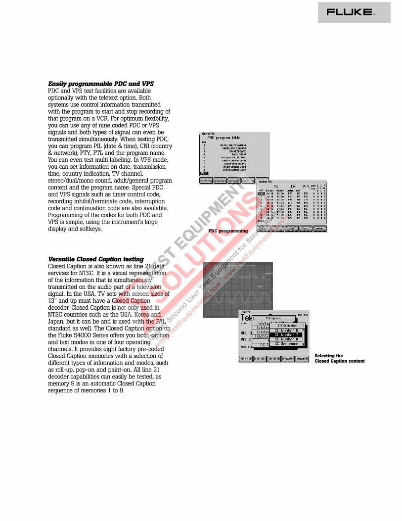
Fluke 54100 Video Signal Generator models (option included):541 00 541 00 541 00 541 00
M01 /nnn P01 /nnn N01 /nnn S01 /nnnPAL standard • •NTSC standard • •SECAM standard • •Teletext + WSS • • •PDC + VPS • • •Closed Caption • •RGB + YC + YCrCb • • • •IEEE + RS-232 • • • •
Fluke 542 00 T V Signal Generator models (option included):54200 54200 54200 54200
M01 /nnn P01 /nnn N01 /nnn S01 /nnnPAL standard • •NTSC standard • •SECAM standard • •Teletext + WSS • • •PDC + VPS • • •Closed Caption • •RGB + YC + YCrCb • • • •IEEE + RS-232 • • • •Analog stereo • • • •NICAM stereo • • •BTSC stereo • •
O perating manual languages and line cords (/nnn v ersions):Europa U SA U K Sw iss Australia
English /001 /003 /004 /005 /008French /011 /013 - /015 -German /021 - - /025 -

®
Fluke CorporationP.O. Box 9090, Everett, WA 98206
Fluke Europe B.V.P.O. Box 1186, 5602 BD Eindhoven, The Netherlands
For more information call:In the U.S.A.: (800) 443-5853 or Fax: (425) 356-5116In Europe/M-East: +31 (0)40 2 678 200 or Fax: +31 (0)40 2 678 222In Canada: (905) 890-7600 or Fax: (905) 890-6866From other countries: +1(425) 356-5500 or Fax: +1 (425) 356-5116 Web access: http://www.fluke.com
©Copyright 1998 Fluke Corporation.All rights reserved.
Installation accessories
54091 19” rackmount
T V System options(tick at least one)
54011 PAL standard 54012 NTSC standard 54013 SECAM standard
Basic models (tick at least one)
54100/nnn Video Signal Generator 54200/nnn TV Signal Generator
Data service options
54021 Teletext + WSS 54022 PDC + VPC (only in
combination with option 54021) 54023 Closed Caption
Interface options
54031 RGB + YC + YCrCb 54032 IEEE + RS-232 interface
Sound options (for 54200/nnn onlytick at least one)
54061 Analog stereo 54062 NICAM stereo 54063 BTSC stereo
R emark: options are also service centerretrofittable
Customer specified configurations
Example: 54100/021 + 54011 + 54021 + 54022 + 54032 + 54091Fluke 54100 Video Signal Generator with a German language Operatingmanual, an European line cord, PAL standard, Teletext + WSS, PDC +VPC, IEEE + RS-232 and 19” rackmount.
Please contact your Fluke sales representative to optimize theconfiguration to your personal requirements.
Operating manual languages and line cords (/nnn versions):Europa USA UK Swiss Australia
English /001 /003 /004 /005 /008French /011 /013 - /015 -German /021 - - /025 -

ENVIRONMENTAL CONDITIONSEnvironment: Laboratory equipment Class 5
(MIL-T-28800D)Warming-up time: 30 minRecalibration interval: 12 monthsTemperature: +22 to +24 °C for reference temperature
0 to +50 °C for operating-20 to +71 °C for non-operating
Reliability: MTBF = 20,000 hoursHumidity, altitude, vibration and shock: MIL-T-28800D (Class 5)Safety: EN 61010-1 +/A2, Class I
IEC 1010-1 +A1 +A2, Class ICAN/CSA-C22.2 No 1010.1, Class I
EMC: EN 55011, Group 1, Class BVDE 0875, Part 11, Group 1, Class BCISPR 11, Group 1, Class BFCC Part 15J, Class A
POWER REQ UIREMENTSLine voltage operating: 90 to 264VLine frequency: 47.5 to 63 HzPower consumption: 60W
DIMENSIONS and WEIGHTWidth: 323 mm (12.72 in)Height: 147 mm (5.79 in)
132.5 mm (5.22 in) without feet (≈3HE)Depth: 417 mm (16.42 in)Weight: Net 9.8 kg (21.6 lb)
Shipping 11.4 kg (25.1 lb)
Values stated without tolerances are typical values
General Specifications
Fluke CorporationPO Box 9090, Everett, WA 98206
Fluke Europe B.V.PO Box 1186, 5602 BD Eindhoven,The Netherlands
For more information call:In the U.S.A.: (800) 443-5853 orFax: (206) 356-5116In Europe/M-East: +(3140) 2 678200 or Fax: +(3140) 2 678 222In Canada: (905) 890-7600 orFax: (905) 890-6866From other countries: +1(206)356-5500 or Fax: +1(206) 356-5116 Web access: http://www.fluke.com
©Copyright 1996 Fluke Corporation.All rights reserved. Printed in the Netherlands 11/96.Date subject to alteration without notice.XXXXXXXX Rev xxxxx
®