Embed Size (px)
Citation preview
911146Revision 0
ENGINEERING SERVICES FOR THE NEXT GENERATION NUCLEAR PLANT (NGNP) WITH
HYDROGEN PRODUCTION
Test Plan for Primary Circuit and Balance of Plant Instrumentation
Prepared by General Atomics For the Battelle Energy Alliance, LLC
Subcontract No. 00075309 Uniform Filing Code UFC:8201.3.1.2
GA Project 30302
CM Aprvd
ISSUED2008/12/09

Test Plan for Primary Circuit and Balance of Plant Instrumentation 911146/0
iii
TABLE OF CONTENTS ACRONYMS AND ABBREVIATIONS.......................................................................................... v1 INTRODUCTION............................................................................................................... 11.1 Scope ................................................................................................................................ 11.2 Purpose............................................................................................................................. 11.3 Applicable Documents ...................................................................................................... 12 TRL 3 TO 4 — BENCH SCALE TESTING OF AVAILABLE INSTRUMENTATION ........ 32.1 Testing Considerations ..................................................................................................... 42.1.1 Primary Circuit Leak Detection Equipment ..................................................................... 52.1.2 Helium Flow Rate Measurement..................................................................................... 52.1.3 Plateout Probe Instrumentation ...................................................................................... 62.1.4 Moisture Ingress Detection Instrumentation ................................................................... 62.1.5 BOP Protection Instrumentation ..................................................................................... 72.2 Test Configuration and Setup ........................................................................................... 82.3 Test Deliverables ..............................................................................................................92.4 Cost and Schedule............................................................................................................ 93 TRL 4 TO 5 — INSTRUMENTATION TESTING AT COMPONENT LEVEL.................. 113.1 Testing Considerations ................................................................................................... 113.1.1 Moisture Detection Sensors.......................................................................................... 123.1.2 Plateout Probes ............................................................................................................ 123.2 Test Configuration and Setup ......................................................................................... 133.3 Test Deliverables ............................................................................................................ 133.4 Cost and Schedule.......................................................................................................... 144 TRL 5 TO 6 — PILOT SCALE TESTING ....................................................................... 154.1 Testing Considerations ................................................................................................... 154.2 Test Configuration and Setup ......................................................................................... 154.2.1 Moisture Detection Sensors.......................................................................................... 164.2.2 Helium Flow Rate.......................................................................................................... 174.2.3 Balance of Plant Instrumentation.................................................................................. 174.2.4 Reactor Building Instrumentation.................................................................................. 184.2.5 Plateout Probe .............................................................................................................. 184.3 Test Deliverables ............................................................................................................ 184.4 Cost and Schedule.......................................................................................................... 195 TRL 6 TO TRL 7 — PRE-INSTALLATION TESTING .................................................... 205.1 Testing Considerations ................................................................................................... 215.2 Test Configuration and Set-up ........................................................................................ 215.2.1 Acceptance Testing ...................................................................................................... 215.2.2 Integrated System Operability Testing.......................................................................... 215.2.3 Seismic Testing ............................................................................................................ 225.3 Test Deliverables ............................................................................................................ 225.4 Cost and Schedule.......................................................................................................... 236 TRL 7 TO TRL 8 — HOT STARTUP READINESS TESTING........................................ 246.1 Testing Considerations ................................................................................................... 246.2 Test Configuration and Setup ......................................................................................... 246.3 Test Deliverables ............................................................................................................ 25
Test Plan for Primary Circuit and Balance of Plant Instrumentation 911146/0
iv
6.4 Cost and Schedule.......................................................................................................... 257 OVERALL SCHEDULE FOR PCBOP DEVELOPMENT................................................ 27
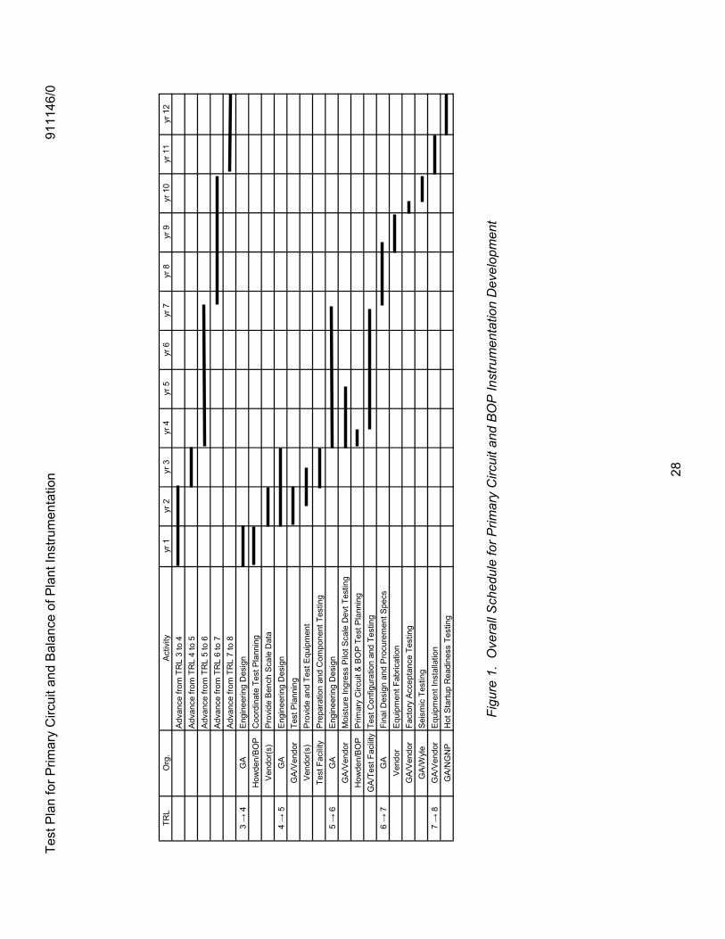
LIST OF FIGURES Figure 1. Overall Schedule for Primary Circuit and BOP Instrumentation Development ...........28
LIST OF TABLES Table 1. Applicable Documents ...................................................................................................1Table 2. Costs Estimates for Primary Circuit and BOP Instrumentation Testing .......................10Table 3. Cost Estimates for Component Testing .......................................................................14Table 4. Costs Estimates for Pilot Scale Testing .......................................................................19Table 5. Costs Estimates for Reactor Control Equipment Pre-Installation Testing....................23Table 6. Costs Estimates for Hot Startup Readiness Testing....................................................26
Test Plan for Primary Circuit and Balance of Plant Instrumentation 911146/0
v
ACRONYMS AND ABBREVIATIONS
ALARA As Low As Reasonably Achievable
ASC Auxiliary Service Cask
BOP Balance of Plant
CFR Code Federal Regulation
DDN Design Data Need
DOE Department of Energy
FSV Fort St. Vrain
GT-MHR Gas Turbine Modular Helium Reactor
HTGR High Temperature Gas-cooled Reactor
IPS Investment Protection System
NGNP Next Generation Nuclear Plant
NHSS Nuclear Heat Supply System
PCBOP Primary Circuit and Balance of Plant
PCDIS Plant Control, Data, and Instrumentation System
PLC Programmable Logic Controller
RPS Reactor Protection System
SSC System, Structure, or Component
TBD To Be Determined
TRL Technical Readiness Level
Test Plan for Primary Circuit and Balance of Plant Instrumentation 911146/0
1
1 INTRODUCTION
1.1 Scope
The Primary Circuit and Balance of Plant (PCBOP) instrumentation is a somewhat arbitrary grouping of instrumentation that has been defined (as SSC-15) for the purpose of identifying technology development required for the NGNP. This grouping includes instrumentation for detecting primary coolant leakage through measurement of pressure, temperature, or radiation levels within the Reactor Building or in helium-to-helium heat exchanger piping which penetrates the Reactor Building; and moisture monitoring and pressure instrumentation for steam leakage detection, operator information, and as a protection-logic, reactor-trip parameter. It also includes plateout instrumentation to monitor and ascertain the level of radioactive plateout within the primary circuit. Helium flow-rate measurements are also included, because the helium flow measurement instrumentation is incorporated into the circulator system design, in each of the helium flow circulators. Finally, the instrumentation for Balance-of-Plant (BOP) measurements, including steam or feedwater flow rate, temperature, and pressure instrumentation contained in the steam-electric (BOP) equipment, complete the SSC-15 instrumentation group.
The PCBOP instrumentation is a critical part of the Reactor Protection System (RPS) and Investment Protection System (IPS). The Moisture Monitoring instrumentation provides a safety-related input to the reactor trip system, as well as providing operator information which will alert operators at the RPS and PCDIS operating consoles in the event of steam leakage into the helium circuits. Likewise, instrumentation to detect helium leakage and provide operator warnings or activation of safety-related Reactor Building isolations functions is important to the reactor safety design. All previous MHR designs have included this type equipment.
This Test Plan outlines the testing and design information needed to advance the PCBOP instrumentation to a “hot startup” readiness level for NGNP operation. It addresses the technical issues that require developmental and confirmatory testing at each technology readiness level (TRL).
1.2 Purpose
The purpose of this test plan is to estimate the necessary testing for key instrumentation in the Reactor Control and Protection systems. DDNs from earlier design efforts, and the related design issues, are the basis used here to approximate the instrumentation technology advancement process.
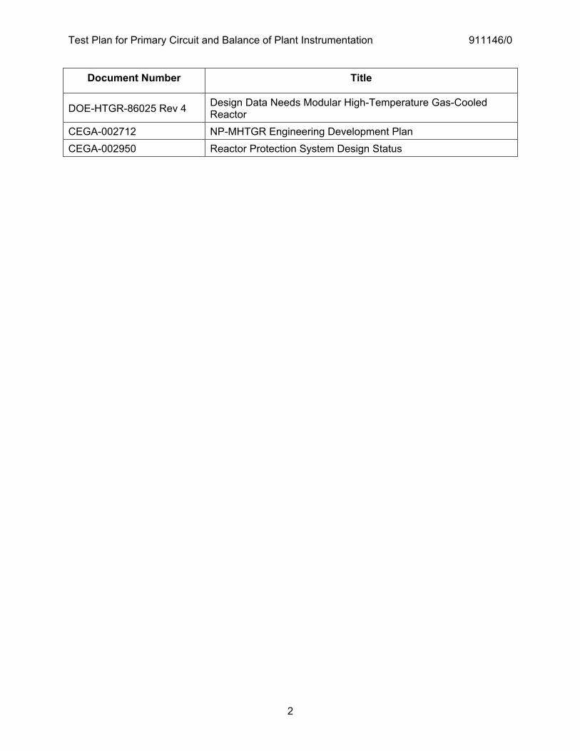
1.3 Applicable Documents
Table 1. Applicable Documents
Test Plan for Primary Circuit and Balance of Plant Instrumentation 911146/0
2
Document Number Title
DOE-HTGR-86025 Rev 4 Design Data Needs Modular High-Temperature Gas-Cooled Reactor
CEGA-002712 NP-MHTGR Engineering Development Plan CEGA-002950 Reactor Protection System Design Status
Test Plan for Primary Circuit and Balance of Plant Instrumentation 911146/0
3
2 TRL 3 TO 4 — BENCH SCALE TESTING OF AVAILABLE INSTRUMENTATION
The initial technology readiness level (TRL) of 3 is assigned to items included in the PCBOP instrumentation grouping. This is primarily because new technology must be evaluated in areas of moisture monitoring and plateout probe instrumentation, which will be provided in the NHSS design. Based on the experience gained at Fort St. Vrain (FSV) and the considerable conceptual design effort in both the commercial MHR program and the NPR program, other areas of this grouping receive a higher initial TRL rating level. Since available US gas-reactor operating experience is outdated, a new database is required to achieve the TRL 4 rating to allow NGNP application of instrumentation used outside the nuclear industry, or to confirm application of instrumentation used in other high-temperature reactor development work in Japan, etc. For example, application of laser technology to moisture detection devices has come about since the development of the High-Temperature Gas-Cooled Reactor for the FSV nuclear generating station. Available instrumentation which would undergo development for use in the NHSS MHR requires updating the TRL before application in the NGNP. That would precede the conceptual design of the instrumentation. The planning of test efforts will be preceded by the following steps:
� Complete the basic concept design for the NHSS. This would include definition of Vessel Systems, Power Conversion Systems, and the Reactor Building. The primary and secondary helium system configurations must also be known.
� From preliminary IHX piping and Reactor Building design information, select leak detection instrumentation locations in Reactor Building and hydrogen production facilities. Also select method of detection — pressure change, temperature change, radiation detection etc. Provide bench scale calculations to correlate leak magnitude and pressure/temperature changes in the Reactor Building.
� Provide supporting design analysis of component operating conditions. Complete interrelated design calculations (e.g. nominal Reactor Building helium temperature and pressure conditions).
� Search available databases for instrumentation techniques capable of moisture monitoring and plateout measurement in the primary helium circuit. Resolve issues which do not require testing to verify, and list all design issues which do require testing of candidate instrumentation techniques. All data which is marginal or questionable, and can be resolved at the component testing level should be verified at this point.
� Determine tests required for instrumentation considered for use in the NHSS and Reactor Building.
Test Plan for Primary Circuit and Balance of Plant Instrumentation 911146/0
4
2.1 Testing Considerations
Testing information and materials must be determined from the Design Data Needs (DDNs) for component development as identified below, or during the early conceptual design phase. Categories for the types of information and materials needed are listed below:
� Calibrated Power Supply and Calibrated Electronic Testers for testing electronic components. These should be available with their test articles.
� Instrumentation calibration standards applied to instrumentation for which data is being obtained. These should be available from manufacturers.
� Data available from manufacturers for operation of the device, enclosure of the device, and electrical power supply required, signal cables, etc. Data provided by manufacturers should be verified to the extent possible after being collected before it is included in the data base.
� Manufacturers’ Verification Certificates. � Test data available from development of specifications for the measurement equipment.
For example, Tests which determine leakage should through mounting seals, etc. would be of particular values in terms of type of fluid, operating conditions, etc.
� Quality assurance documentation providing requirements for conducting experimental or validation testing of non-safety and safety-related components.
Tests conducted to nuclear industry standards will require the following applicable Federal, State and local code documentation:
� 10 CFR 32.57, Calibration or reference sources containing americium-241 or radium-226: Requirements for license to manufacture or initially transfer (if applied)
� 10 CFR 71, Packaging and Transporting, Radioactive materials � 10 CFR 835, Occupational Radiation Protections. � 29 CFR 1910, Occupational Safety and Health Standards. � 40 CFR 1502, Environment Impact Act. � DOE O 420.1A, Facility Safety
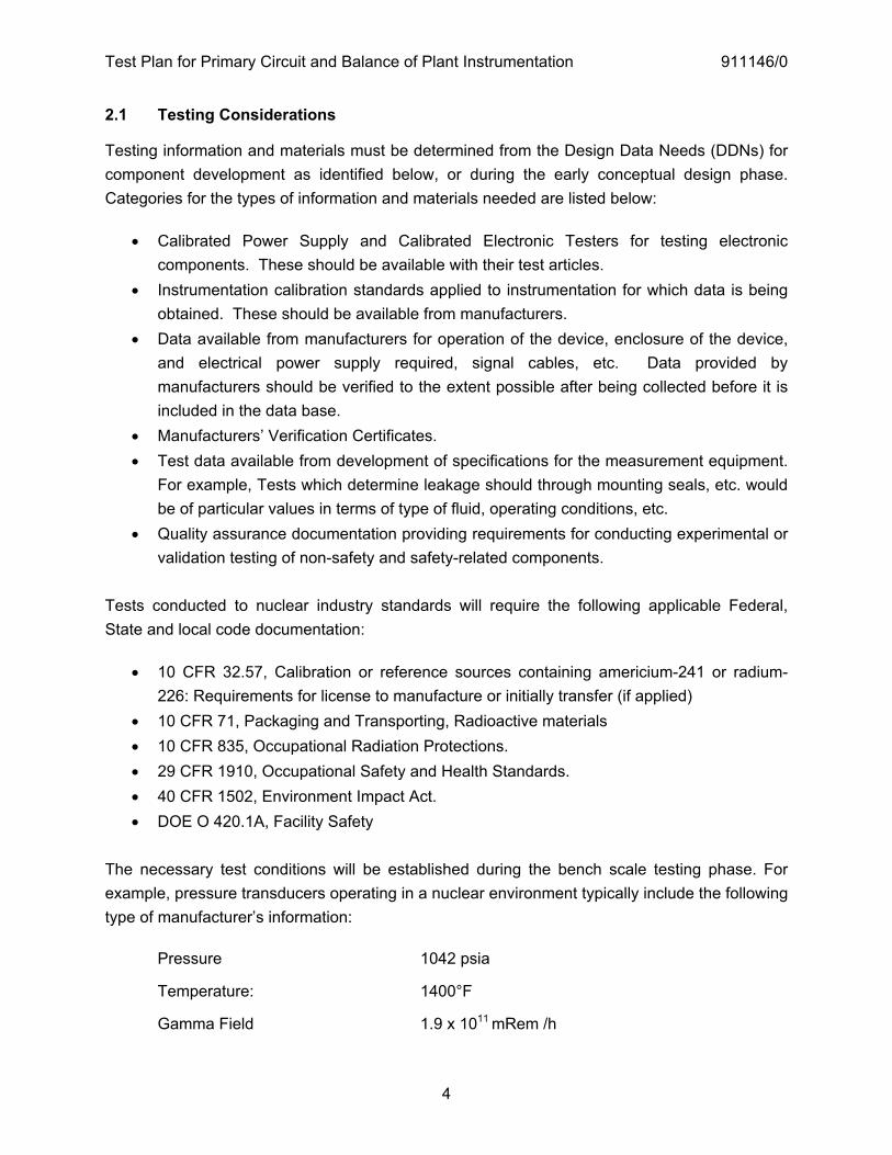
The necessary test conditions will be established during the bench scale testing phase. For example, pressure transducers operating in a nuclear environment typically include the following type of manufacturer’s information:
Pressure 1042 psia
Temperature: 1400°F
Gamma Field 1.9 x 10¹¹ mRem /h
Test Plan for Primary Circuit and Balance of Plant Instrumentation 911146/0
5
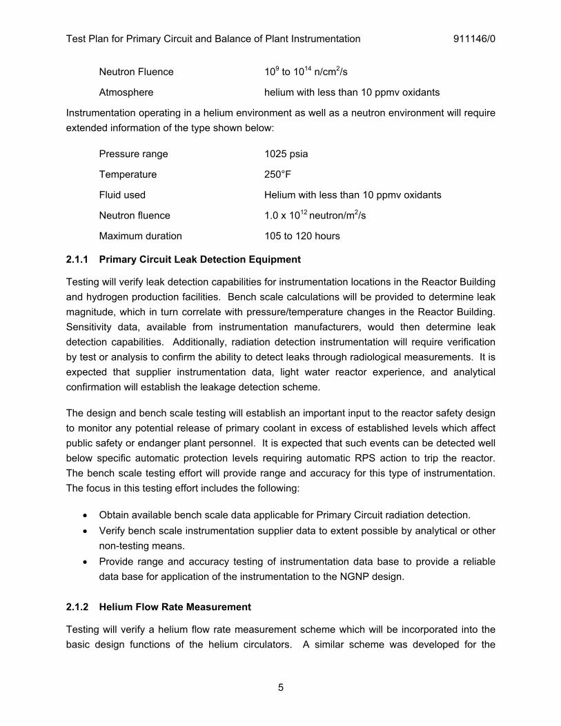
Neutron Fluence 109 to 1014 n/cm2/s
Atmosphere helium with less than 10 ppmv oxidants
Instrumentation operating in a helium environment as well as a neutron environment will require extended information of the type shown below:
Pressure range 1025 psia
Temperature 250°F
Fluid used Helium with less than 10 ppmv oxidants
Neutron fluence 1.0 x 10¹² neutron/m2/s
Maximum duration 105 to 120 hours 2.1.1 Primary Circuit Leak Detection Equipment
Testing will verify leak detection capabilities for instrumentation locations in the Reactor Building and hydrogen production facilities. Bench scale calculations will be provided to determine leak magnitude, which in turn correlate with pressure/temperature changes in the Reactor Building. Sensitivity data, available from instrumentation manufacturers, would then determine leak detection capabilities. Additionally, radiation detection instrumentation will require verification by test or analysis to confirm the ability to detect leaks through radiological measurements. It is expected that supplier instrumentation data, light water reactor experience, and analytical confirmation will establish the leakage detection scheme.
The design and bench scale testing will establish an important input to the reactor safety design to monitor any potential release of primary coolant in excess of established levels which affect public safety or endanger plant personnel. It is expected that such events can be detected well below specific automatic protection levels requiring automatic RPS action to trip the reactor. The bench scale testing effort will provide range and accuracy for this type of instrumentation. The focus in this testing effort includes the following:
� Obtain available bench scale data applicable for Primary Circuit radiation detection. � Verify bench scale instrumentation supplier data to extent possible by analytical or other
non-testing means. � Provide range and accuracy testing of instrumentation data base to provide a reliable
data base for application of the instrumentation to the NGNP design. 2.1.2 Helium Flow Rate Measurement
Testing will verify a helium flow rate measurement scheme which will be incorporated into the basic design functions of the helium circulators. A similar scheme was developed for the
Test Plan for Primary Circuit and Balance of Plant Instrumentation 911146/0
6
circulators that were used at Fort St. Vrain, and will be used in the NGNP design. The steps involved in development of the flow measurement instrumentation are as follows:
� Contact circulator design team and verify incorporation of Helium Mass Flow Measurement in Circulator development effort. The circulator integrated instrumentation may also include safety-related primary helium temperature and pressure measurements.
� Develop a schedule for design and testing which is compatible with development of safety-related measurement and protection equipment included in the Reactor Protection System and the PCDIS.
Test facilities for this instrumentation will be established by the circulator designer(s).
2.1.3 Plateout Probe Instrumentation
This instrumentation is required to meet anticipated Technical Specifications for operation of the MHR reactor and address issues concerning possible release of primary coolant from the reactor. Design Data Needs (DDNs) have been written to describe these. The following activities are expected to reach a level 4 TRL rating for this portion of the instrumentation:
� Provide bench-scale calculations for Plateout Probe instrumentation to determine fission product deposition levels.
� Acquire available plate-out technology information, such as OGL-1 plate-out measurement techniques, etc.
� Establish a database from the information gathered, and develop a test plan for level 4 bench scale testing and preliminary planning for post TRL 4 testing.
Facilities to test the plateout probe instrumentation will be developed, and possibly can be done at one of several nuclear testing facilities including Idaho National Laboratory (INL), Oak Ridge National Laboratory (ORNL), etc.
2.1.4 Moisture Ingress Detection Instrumentation
This instrumentation is required to detect and protect the reactor and primary circuit in the event of steam generator failures, such as an offset-tube-rupture event or a lesser event that allows steam to enter the primary coolant circuit. In the nuclear-steam electric generating plant, the steam generator moisture ingress detection sensors are part of the safety-related Reactor Protection System. Since new technology is required, the Moisture Ingress Detection System is included in the bench scale verification effort. The following activities are needed to reach a TRL 4 rating for this portion of the instrumentation:
Test Plan for Primary Circuit and Balance of Plant Instrumentation 911146/0
7
� Provide bench-scale calculations for moisture detection instrumentation. Coordinate with Steam Generator, Reactor System, BOP Isolation and Dump System, etc. conceptual design efforts to establish bench scale criteria for selection of instrumentation.
� Survey and available commercial moisture monitoring equipment. � Obtain manufacturers information for Primary Circuit Instrumentation Database. � Select possible method(s) for moisture detection from potentially available commercial
technology such as Cavity Ring-Down Spectroscopy (CRDS). � Review commercial data to determine areas where new information is needed to provide
information that is applicable for NGNP. � Obtain commercial equipment. Perform tests to verify the application of selected
equipment to the moisture detection design. Include bench scale modifications required to provide representative applications of the technology to NGNP.
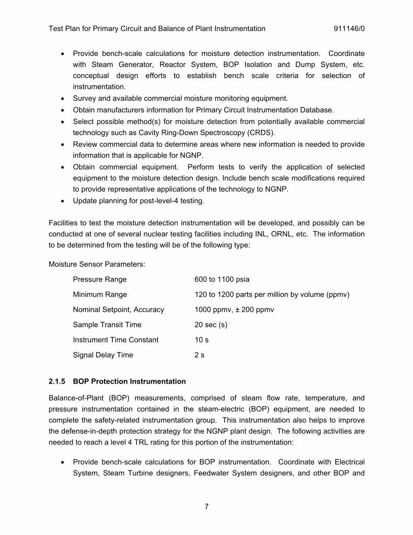
� Update planning for post-level-4 testing. Facilities to test the moisture detection instrumentation will be developed, and possibly can be conducted at one of several nuclear testing facilities including INL, ORNL, etc. The information to be determined from the testing will be of the following type:
Moisture Sensor Parameters:
Pressure Range 600 to 1100 psia
Minimum Range 120 to 1200 parts per million by volume (ppmv)
Nominal Setpoint, Accuracy 1000 ppmv, ± 200 ppmv
Sample Transit Time 20 sec (s)
Instrument Time Constant 10 s
Signal Delay Time 2 s
2.1.5 BOP Protection Instrumentation
Balance-of-Plant (BOP) measurements, comprised of steam flow rate, temperature, and pressure instrumentation contained in the steam-electric (BOP) equipment, are needed to complete the safety-related instrumentation group. This instrumentation also helps to improve the defense-in-depth protection strategy for the NGNP plant design. The following activities are needed to reach a level 4 TRL rating for this portion of the instrumentation:
� Provide bench-scale calculations for BOP instrumentation. Coordinate with Electrical System, Steam Turbine designers, Feedwater System designers, and other BOP and
Test Plan for Primary Circuit and Balance of Plant Instrumentation 911146/0
8
AE design teams during the conceptual design efforts to establish bench scale criteria for safety-related instrumentation requirements.
� Verify preliminary range, sensor accuracy, response, etc. for reactor control and protection instrumentation located in BOP. Include parameters such as the turbine-trip-command signal and include measurements such as steam temperature, pressure, flow, feedwater temperature, turbine bypass flow rate, etc.
� Obtain commercial equipment. Perform bench scale reactor control, transient calculations to determine instrumentation response requirements.
� Determine areas where new information is needed to assure instrumentation is applicable for NGNP.
� Update instrumentation reliability data from available nuclear-electric plant database. Include measurement redundancy, sensor fail-over techniques, signal transmission quality, etc.
� Update planning for post TRL 4 testing. 2.2 Test Configuration and Setup
Bench scale testing configurations, as available at vendor locations, will also be reviewed to determine configurations, facilities, etc. for follow-on testing activities.
Extension of manufacturers’ data will probably continue at the original testing facilities. Facilities for the primary circuit instrumentation testing will include some evaluation of radiation effects. Manufacturers may not supply this information, and bench-scale testing may be needed to obtain the data. All the detectors require handling operations for maintenance and inspection, as well.
Any testing to extend manufacturers data will require the guidance of the instrumentation manufacturer in locating the original testing facilities, and may require subsequent review of these facilities. However, some key issues regarding the Reactor Control and Protection systems development currently exist to suggest criteria for selecting facilities to extend the data base for components being considered during the early part of conceptual design. These are as follows:
� High temperature and pressure in a helium environment, and prolonged operation at equivalent conduction cooldown conditions.
� The testing facility must be able to simulate normal and abnormal reactor operation, pressurized and depressurized conditions, etc. in helium. Therefore, the capability to create a variety of pressure, temperature, and helium flow conditions will be required.
Tests can be done at several nuclear testing facilities such as INL, ORNL, etc.
Test Plan for Primary Circuit and Balance of Plant Instrumentation 911146/0
9
2.3 Test Deliverables
All test equipment and instrumentation data should be reviewed, calibrated, with documentation maintained etc. beforehand. All operational discrepancies should be included in the Test Report, which should include, as a minimum:
� Detailed discussion of operation � Equipment employed � Equipment calibration verification � Detailed test procedures � Original test data � Summarized and reduced test data
A detailed discussion of test results, observations, and calculations that were completed throughout the course of testing, would also be included.
The final report should be available prior to completion of conceptual design, and should be prepared for inclusion in Reactor Protection System documentation.
2.4 Cost and Schedule
Tests will be performed early in the conceptual design phase.
Test Plan for Primary Circuit and Balance of Plant Instrumentation 911146/0
10
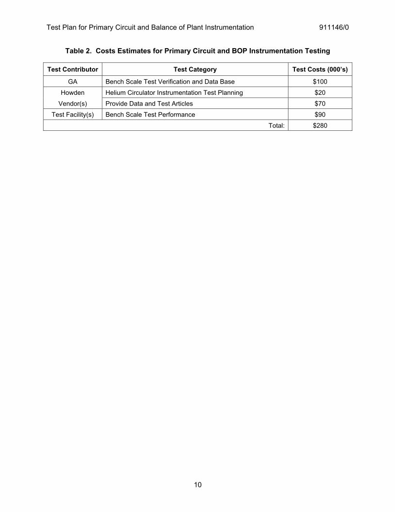
Table 2. Costs Estimates for Primary Circuit and BOP Instrumentation Testing
Test Contributor Test Category Test Costs (000’s)
GA Bench Scale Test Verification and Data Base $100
Howden Helium Circulator Instrumentation Test Planning $20
Vendor(s) Provide Data and Test Articles $70
Test Facility(s) Bench Scale Test Performance $90
Total: $280
Test Plan for Primary Circuit and Balance of Plant Instrumentation 911146/0
11
3 TRL 4 TO 5 — INSTRUMENTATION TESTING AT COMPONENT LEVEL
Design issues may arise from bench scale testing efforts, and these should be documented prior to completion of conceptual design. It is anticipated that the Moisture Detection System and the Plateout Probe will require additional testing at the component level.
Achievement of TRL 5 will also require specific design selections from the available devices selected for TRL 4 testing. Specific components within the instrumentation assemblies will also be determined, and testing will be needed to assure reliability, availability, maintainability, etc. Industrial data, provided by vendors, will also be reviewed to determine if further testing or other means of updating the database is required to achieve TRL 5. It is expected that component level testing will required primarily for the moisture monitoring and plateout probe systems.
The method for development of the component testing efforts will consist of the following steps:
� Complete NHSS conceptual instrumentation design and coordinate with interfacing design areas – Reactor Building, BOP, etc. Provide preliminary views of each installed system and operational requirements for radiation detection, pressure, temperature, etc. measurement. Document design issues.
� Provide supporting design analysis of component operating conditions. Complete interrelated design efforts (e.g. Reactor fuel design, Steam Generator design, Intermediate Heat Exchanger design, Circulator design, Steam Power Conversion system design, etc), and assure compatibility of interrelated instrumentation.
� Resolve design issues which do not require component testing, and list all design issues which do require component testing.
� Specify experimental scale tests. Continue testing based on bench scale testing activities.
It should be noted that circulator testing to develop the helium flow measurement scheme will be conducted through the circulator development team. Therefore, the instrumentation design effort involves coordination, but not testing. Helium flow rate measuring instrumentation, although not within the reactor design scope, is controlled and monitored through the reactor control and protection interfaces, and remains a very important part of the reactor protection equipment.
3.1 Testing Considerations
Industrial proof-of-concept data, provided by vendors, will be reviewed to determine if further testing or other means of updating the database is required to achieve the TRL 5 rating. It is expected that most of this type of testing will involve MHR-specific instrumentation systems,
Test Plan for Primary Circuit and Balance of Plant Instrumentation 911146/0
12
whereas instrumentation that will be used in the MHR, but which is also common to the light water reactor industry, is well qualified.
Conceptual design activities will also provide a range of plant operations and analysis to determine the helium flow rate measuring system requirements. These will be provided to the circulator development team, since pressure probes, piping and temperature sensors, etc. located within the helium circulators provides the helium flow rate instrumentation.
Reactor control/protection analysis during conceptual design will also provide measurement requirements for steam-electric (BOP) equipment, such as steam flow rate, temperature, and pressure instrumentation. The updated information will be provided to establish nuclear control and BOP electric-plant design requirements for the later design. However, the BOP instrumentation is well established in nuclear electric plants, and so will not require verification testing, other than that provided in BOP development activities.
The expected activities during component development to determine the need for testing are explained below.
3.1.1 Moisture Detection Sensors
Specific experimental scale tests will be required if instrumentation for moisture detection is modified specifically for NGNP. New considerations will involve NGNP piping and attachment systems, improvement of original detection methods, operation in the MHR NGNP environment, etc. The following activities are expected in planning and completing the component level test effort:
� Determine vendor of Steam Generator Moisture Ingress Detection Sensors. � Verify available data based on bench scale testing and data from available commercial
moisture monitoring equipment. Identify data which is still needed at the component test level. Specify experimental scale tests to verify.
� Perform reliability analysis for components contained in moisture detection equipment. Prepare test plan to resolve uncertainties.
� Complete testing is required to complete updates to bench scale test results and to resolve component uncertainties.
� Verify application of data to Steam Generator Moisture Ingress Detection Sensor design.
3.1.2 Plateout Probes
Testing may also be needed at the component level for these devices. Testing requirements will be determined during the conceptual design. It may be possible to combine some of the component testing with fuel or other reactor component testing, which will occur at this time.
Test Plan for Primary Circuit and Balance of Plant Instrumentation 911146/0
13
3.2 Test Configuration and Setup
Component development testing during the conceptual design phase will require the same information and materials needed earlier in the bench-scale testing.
Testing to extend manufacturers data will probably continue at the original testing facilities, and key issues regarding the PCBOP instrumentation will remain the same. However, new information will be available for testing which occurs near the end of conceptual design. The key test configuration guidelines remain as follows:
� High temperature and pressure in a helium environment, and prolonged operation at equivalent conduction cooldown conditions.
� The testing facility must be able to simulate normal and abnormal reactor operation, pressurized and depressurized conditions, etc. in helium. Therefore, the capability to create a variety of pressure, temperature, and helium flow conditions will be required.
Tests can be done at several nuclear testing facilities such as INL, ORNL, etc.
Failure modes will be determined at the pilot scale. Failure modes and effects are likely to be key concerns for design of the Moisture Detection Sensors. Also, any issues preliminary to starting the final design are to be resolved here. The following activities are expected in planning and completing the component level test effort:
� Update reliability analysis based on component testing of moisture detection equipment. Prepare test plan to resolve uncertainties and determine failure-mode-effects. Asses the need for accelerated life testing
� Complete testing and provide information for final design effort. 3.3 Test Deliverables
All test equipment and instrumentation data should be reviewed, calibrated, with procedure documentation etc. provided beforehand. All operational discrepancies should be included in the Test Report, which should include, as a minimum:
� Detailed discussion of operation � Equipment employed � Equipment calibration verification � Detailed test procedures � Original test data � Summarized and reduced test data
Test Plan for Primary Circuit and Balance of Plant Instrumentation 911146/0
14
A detailed discussion of test results, observations, and calculations that were completed throughout the course of testing, would also be included.
The final report should be available prior to completion of conceptual design.
3.4 Cost and Schedule
Tests will be performed during the last year of the conceptual design phase.
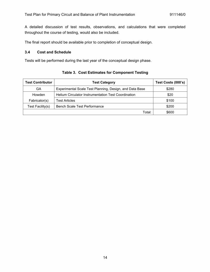
Table 3. Cost Estimates for Component Testing
Test Contributor Test Category Test Costs (000’s)
GA Experimental Scale Test Planning, Design, and Data Base $280
Howden Helium Circulator Instrumentation Test Coordination $20
Fabricator(s) Test Articles $100
Test Facility(s) Bench Scale Test Performance $200
Total: $600
Test Plan for Primary Circuit and Balance of Plant Instrumentation 911146/0
15
4 TRL 5 TO 6 — PILOT SCALE TESTING
TRL 5 is achieved when the activities described In Section 3 are successfully completed and all necessary component test. These activities provided component testing of the PCBOP instrumentation required in NGNP. The TRL 4 level testing and analytical assessments supporting the NGNP design application provided the basis to start preliminary design activities.
4.1 Testing Considerations
Instrumentation associated with the primary circuit and the balance of plant will be placed in the primary helium circuit or reactor building to detect leakage of radioactive materials, potentially affecting the public or plant personnel. Other instrumentation, such as the moisture sensors, the BOP instrumentation, and the circulator helium flow instrumentation, provides safety-related measurements for operator information and for automatic action which is accomplished by the Reactor Protection System.
The need for subsystem testing will be determined by review of vendor development efforts and the results of previous testing. If subsystem testing is necessary, this type of testing is only expected for advanced instrumentation systems, such as the moisture monitoring and plateout probe systems. No subsystem testing is expected for the conventional instrumentation contained in the primary circuit and balance of plant. Achievement of TRL 6 will be provided by analytical confirmation for this type of instrumentation. Likewise, coordination with the circulator development team will determine the need for helium flow rate instrumentation testing. If necessary, this testing will be accomplished with other circulator subsystem testing, and will be conducted under the circulator development scope. It is likely that seismic testing of the helium flow rate measurement system will be more helpful to the circulator overall design if performed at the subsystem level. For purposes of this document however, it is assumed that seismic testing will occur at TRL 7. 4.2 Test Configuration and Setup
The test configuration must be determined during the preliminary phase of final design, based on information derived during that phase of the design effort. The setup – including data base, procedural documentation, testing equipment, etc. -- will probably be very similar to the test facilities used for component testing. It would be advisable to consider the possibilities for expansion of the facilities during the component development phase of testing. The expected procedure for determining the tests to be performed, the issues to be resolved, the data to be confirmed, etc. is listed briefly below:
� Complete NHSS the first half of the Final Design effort.
Test Plan for Primary Circuit and Balance of Plant Instrumentation 911146/0
16
� Provide subsystem and final assembly views and supporting analysis to determine operating conditions for each of the instrumentation subsystems.
� Document remaining design issues. � Coordinate with interfacing design areas Include detector assembly operating integrity.
Complete interrelated subsystem development efforts. � Resolve design issues which do not require specific subsystem testing, using analysis or
test data from qualified similar applications. For example, it is expected that issues arising in the BOP instrumentation can be resolved by review of similar instrumentation that has been used extensively in the light water reactor industry.
� List all design issues which do require subsystem testing and determine tests required. � Prepare test facilities for instrumentation mountings, detector subsystems, etc. using
representative versions of the final design. It is expected that the test facilities identified above, with minor modifications, can be used to complete the subsystem testing described below. The difference is that a means of fabrication to provide the pilot-scale test articles and preparations to interface these with the test facilities will be required.
During the early part of preliminary design, with engineering design of the pilot-scale test articles completed, preparation to update the pilot-scale test facilities will be started as well. The test conditions for subsystem test articles will be the same as required for component testing.
One exception to the above summary is the instrumentation that will be placed in the Reactor Building to detect and protect against primary coolant leakage or a sudden failure of the primary coolant boundary. While it is not considered necessary to require component developmental testing of this instrumentation, a basis for validating pressure, temperature, etc. instrumentation sensitivity will be needed for later acceptance testing.
4.2.1 Moisture Detection Sensors
The following activities are expected to achieve a pilot scale technical rating for the moisture sensors:
� Review vendor development of Moisture Ingress Detection Sensors. � Fabricate pilot scale test configuration. � Specify necessary subsystem testing procedures, data requirements etc. � Complete tests, and verify results. � Update analytical results to confirm TRL 6 rating.
Test Plan for Primary Circuit and Balance of Plant Instrumentation 911146/0
17
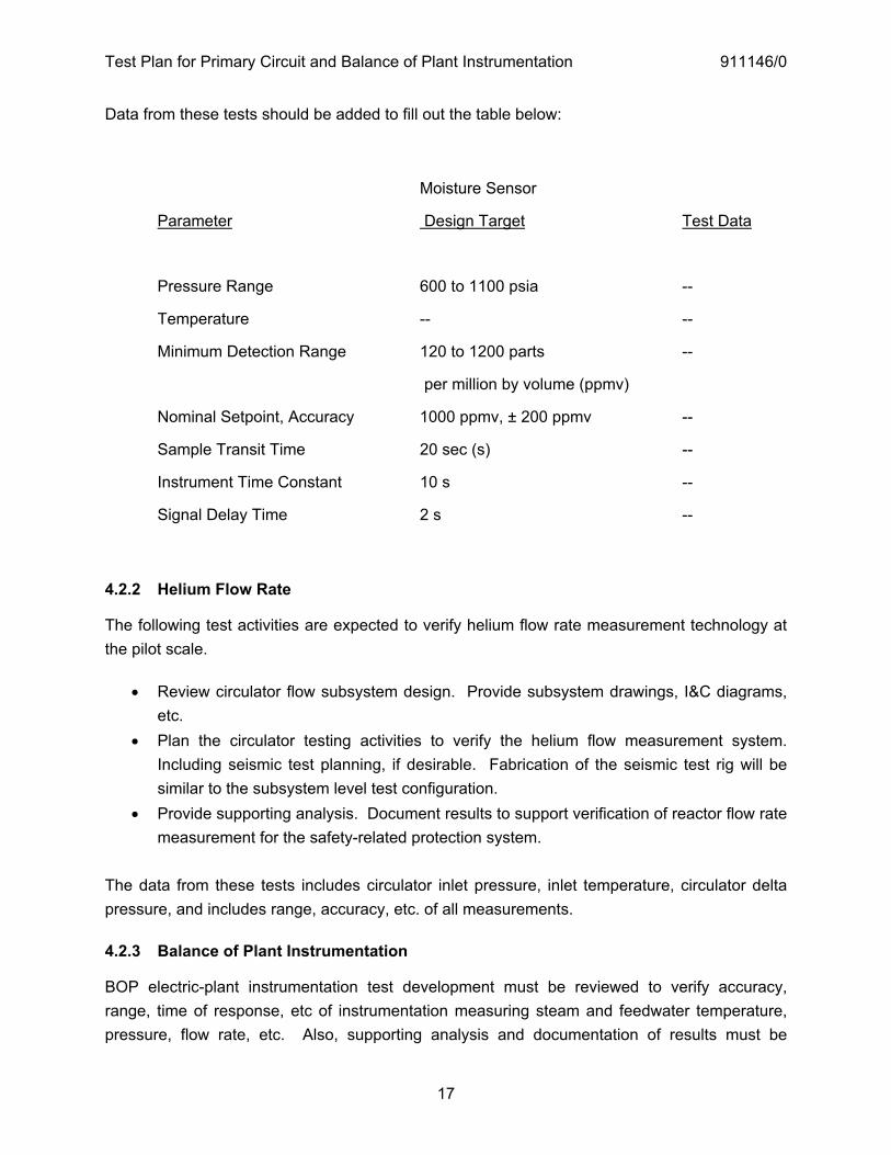
Data from these tests should be added to fill out the table below:
Moisture Sensor
Parameter Design Target Test Data
Pressure Range 600 to 1100 psia --
Temperature -- --
Minimum Detection Range 120 to 1200 parts --
per million by volume (ppmv)
Nominal Setpoint, Accuracy 1000 ppmv, ± 200 ppmv --
Sample Transit Time 20 sec (s) --
Instrument Time Constant 10 s --
Signal Delay Time 2 s --
4.2.2 Helium Flow Rate
The following test activities are expected to verify helium flow rate measurement technology at the pilot scale.
� Review circulator flow subsystem design. Provide subsystem drawings, I&C diagrams, etc.
� Plan the circulator testing activities to verify the helium flow measurement system. Including seismic test planning, if desirable. Fabrication of the seismic test rig will be similar to the subsystem level test configuration.
� Provide supporting analysis. Document results to support verification of reactor flow rate measurement for the safety-related protection system.
The data from these tests includes circulator inlet pressure, inlet temperature, circulator delta pressure, and includes range, accuracy, etc. of all measurements.
4.2.3 Balance of Plant Instrumentation
BOP electric-plant instrumentation test development must be reviewed to verify accuracy, range, time of response, etc of instrumentation measuring steam and feedwater temperature, pressure, flow rate, etc. Also, supporting analysis and documentation of results must be
Test Plan for Primary Circuit and Balance of Plant Instrumentation 911146/0
18
provided to verify reactor control capabilities and confirm ability of PCDIS to accomplish required actions following a reactor trip.
4.2.4 Reactor Building Instrumentation
Review preliminary design data for radiation detection instrumentation and pressure/ temperature measurements to assure capability to detect leakage of primary coolant into the Reactor Building. These test planning activities include:
� Coordination with Reactor Building design efforts. � Preparation of test facilities to duplicate conditions of helium release at various levels.
This will include supporting analysis. � Performance of instrumentation range, accuracy, sensitivity, etc. testing.
4.2.5 Plateout Probe
Subsystem testing of the device may be incorporated with fuel or other reactor testing. Vendor development of the Plateout Probe instrumentation should be reviewed. Analysis should be provided to confirm the TRL 6 rating.
4.3 Test Deliverables
All test equipment and instrumentation data should be processed, reviewed, and documented. Any test equipment deficiencies should be corrected and documented along with test results. All operational discrepancies during testing should be included. Retesting to resolve discrepancies should be described in detail. The Test Report should include as a minimum:
� Detailed discussion of the operation � Equipment employed � Equipment calibration verification � Detailed test procedures � Original test data � Summarized and reduced test data
The subsystem pilot-scale testing will be completed as determined above. Design adjustment and repeat-testing to resolve issues that arise during testing should be clearly documented. Recommendations for pre-installation integrated system level testing of Moisture Monitoring equipment, the Plateout Probes, and radiation monitoring equipment used in the Reactor Building, should be provided. A detailed report describing test results, observations, and calculations that were completed throughout the course of testing should be provided.
The final report should be available within two months after completion of the physical testing.
Test Plan for Primary Circuit and Balance of Plant Instrumentation 911146/0
19
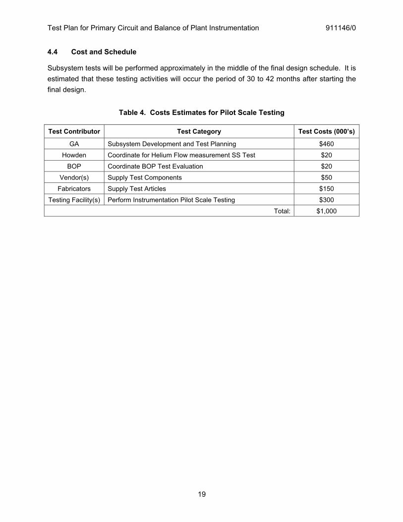
4.4 Cost and Schedule
Subsystem tests will be performed approximately in the middle of the final design schedule. It is estimated that these testing activities will occur the period of 30 to 42 months after starting the final design.
Table 4. Costs Estimates for Pilot Scale Testing
Test Contributor Test Category Test Costs (000’s)
GA Subsystem Development and Test Planning $460
Howden Coordinate for Helium Flow measurement SS Test $20
BOP Coordinate BOP Test Evaluation $20
Vendor(s) Supply Test Components $50
Fabricators Supply Test Articles $150
Testing Facility(s) Perform Instrumentation Pilot Scale Testing $300
Total: $1,000
Test Plan for Primary Circuit and Balance of Plant Instrumentation 911146/0
20
5 TRL 6 TO TRL 7 — PRE-INSTALLATION TESTING
The Primary Circuit and BOP Instrumentation final design is completed under the TRL 6 rating, but demonstration of installation readiness requires further testing to advance from TRL 6 to TRL 7. The major categories of testing are the following:
� System acceptance testing � Integrated system operability testing � Seismic testing
The final design and test planning activities prior to installation are as follows:
� Complete final design. Issue final P&ID drawings for Primary Circuit and Balance of Plant Instrumentation. Coordinate with interfacing design areas – Reactor Building, BOP, etc. to verify pre-installation acceptance test planning and documentation to be completed. Assure updated analysis is provided to define accuracy, reliability, maintainability, etc. of all radiological leak detection instrumentation and for Steam Generator Moisture Ingress Detection Sensors and Plateout Probe instrumentation.
� Fabricate instrumentation. � Monitor vendor acceptance testing. � Complete seismic testing to assure compliance with SSE and OBE operational
requirements. � Document all testing activities to confirm qualification of safety-related protection
instrumentation. � Deliver instrumentation and repeat vendor acceptance tests on-site to validate operation. � Verify instrumentation mounting and cable installation capability. Tests to verify power
cable and instrumentation readiness will utilize available NGNP facilities, including operation of the equipment from the actual or Engineering Scale control consoles.
� Update circulator flow measurement test requirements, from TRL 6 requirements. Combine helium flow rate measurement testing with circulator pre-installation acceptance testing. Provide updated analysis to assure accuracy, reliability, maintainability, etc. of helium flow measurement instrumentation is satisfactory for TRL 7 rating.
� Complete fabrication of circulator systems. Determine seismic testing which needs to be repeated (if not done previously at TRL 6) to assure compliance with SSE and OBE operational requirements. Document to confirm qualification of safety-related helium flow rate instrumentation.
� Review BOP electric-plant instrumentation pre-installation testing. Assure updated analysis is provided to define accuracy, reliability, maintainability, etc. of temperature,
Test Plan for Primary Circuit and Balance of Plant Instrumentation 911146/0
21
pressure, flow rate, etc. instrumentation. Assure seismic testing requirements have been completed. Document for qualification of safety-related protection instrumentation.
5.1 Testing Considerations
The criteria to be used to establishing testing requirements will be the same as the TRL 6 criteria except for seismic testing, which is explained below.
5.2 Test Configuration and Set-up
The pre-installation test configuration is based on earlier design and testing efforts. After completing the NHSS Final Design resolve all issues which do not require testing, using all available information, and document the resolution of these issues. At this point the following general guidelines should be included in test preparation.
� Preparation of test facilities which will be used at NGNP should follow the same procedures as were followed at lower TRL ratings. If equipment adjustments are necessary during testing, repeat testing after adjustments are completed.
� Provide NHSS equipment change information to engineering to modify as-built drawings. � Assure that all levels of Quality Assurance are repeated in the testing process.
Document results to confirm the TRL 7 rating. � Provide recommendations for after-installation-testing.
5.2.1 Acceptance Testing
All of these tests will utilize facilities available at the fabricators site or at NGNP. Testing at NGNP will involve operation of some equipment from the actual or engineering-scale control consoles. Test data recording equipment, available from the engineering-scale PCDIS portion of Reactor Control and Protection systems equipment, should be used for acquisition of data from these tests whenever possible.
5.2.2 Integrated System Operability Testing
In addition to the acceptance testing at NGNP, end-to-end checks of the instrumentation equipment will be performed with the instrumentation connected to power supply and data acquisition equipment. Checkout of electric power wiring must verify cable harnesses, cable tray attachments, etc for each of these systems. This also includes verification of proper cable separation procedures for the reliability and safety-related design requirements of the equipment.
Test Plan for Primary Circuit and Balance of Plant Instrumentation 911146/0
22
5.2.3 Seismic Testing
Seismic testing of Reactor Control and Protection systems is required to achieve a TRL 7 rating. These tests will be accomplished in a nuclear qualified facility. Special test structures to attach equipment and produce as-installed seismic effects, or amplification of the seismic effects to represent the as-installed effects, will be required.
Operability at Safe Shutdown Earthquake (SSE) seismic levels must be demonstrated for safety-related equipment. The SSE magnitude is twice the Operational Basis Earthquake (OBE) magnitude, but the OBE requirement applies to all equipment, and requires that all equipment needed to operate the reactor must continue to operate. This would be a key concern in development of the Moisture Detection Sensors. Therefore, temporary relocation of supporting test equipment to seismic test facilities will be necessary. Test documentation from seismic testing must be provided to support SSE and OBE qualification of the equipment.
These tests will not be performed at NGNP. However, they cannot be done at operating conditions, so the tests will include compensating effects which will be factored into results by analytical means.
Wyle Labs is a provider of seismic testing for nuclear plants and has extensive facilities for this type of testing. The seismic tests will probably be done at these facilities. The following link provides in formation about Wyle Labs:
http://www.wylelabs.com/services/nuclearservices/seismicandequipmentqualificationtestservices.html 5.3 Test Deliverables
All testing equipment and instrumentation data should be processed, reviewed, and documented as before. Any operational discrepancies should be included and the process of retesting to resolve discrepancies should be described in detail. The Test Report should include as a minimum:
� Detailed discussion of the operation � Equipment employed � Equipment calibration verification � Detailed test procedures � Original test data � Summarized and reduced test data
Test Plan for Primary Circuit and Balance of Plant Instrumentation 911146/0
23
NRC acceptance of testing results is necessary at this TRL rating level. Test planning should determine methods to validate installed instrumentation equipment, and should include documentation of remaining issues for that phase of testing.
The final report should be available within one month after completion of the physical testing.
5.4 Cost and Schedule
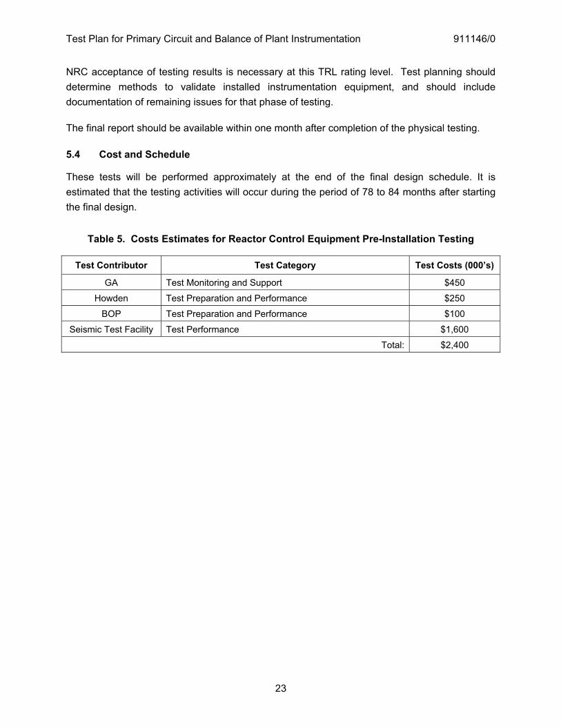
These tests will be performed approximately at the end of the final design schedule. It is estimated that the testing activities will occur during the period of 78 to 84 months after starting the final design.
Table 5. Costs Estimates for Reactor Control Equipment Pre-Installation Testing
Test Contributor Test Category Test Costs (000’s)
GA Test Monitoring and Support $450
Howden Test Preparation and Performance $250
BOP Test Preparation and Performance $100
Seismic Test Facility Test Performance $1,600
Total: $2,400
Test Plan for Primary Circuit and Balance of Plant Instrumentation 911146/0
24
6 TRL 7 TO TRL 8 — HOT STARTUP READINESS TESTING
Testing of the installed instrumentation systems will be needed to confirm hot startup readiness. These tests involve operation of the equipment from the control room, utilizing the Plant Control, Data and Instrumentation System (PCDIS). Reactor Control and Protection development testing therefore includes testing of the as-built and installed equipment. Design adjustments accomplished during the earlier test phases, have maintained necessary procedural steps involving quality assurance, drawing and documentation update, etc.
Testing objectives to advance from a level 7 to a level 8 TRL rating are as follows:
� Validation of the installed equipment. This includes checkout of primary circuit instrumentation, BOP instrumentation, and helium flow rate instrumentation.
� Advancement to TRL 8 by completing qualification of safety-related and non-safety instrumentation for the reactor protection and investment protection functions.
The expected procedure for determining the tests to be performed, the issues to be resolved, the data to be confirmed, etc. is listed briefly below:
� Complete final fabrication of instrumentation equipment and provide as-built drawings showing final assembly views, sub-assembly views, control and instrumentation diagrams, etc. and supporting documentation to allow assembly, installation, test-point hookup procedures for test instruments, etc.
� Document resolution of all pre-installation issues. � Coordinate with interfacing design areas � Install instrumentation equipment and prepare for some duplication of pre-installation
test procedures, including power-up and instrumentation checkouts, using PCDIS. � Perform checkout testing. Confirm all instrumentation testing completion for hot startup
readiness. 6.1 Testing Considerations
The criteria to be used to determining testing requirements to advance from TRL 7 to TRL 8 are the same as the criteria for advancing from TRL 6 to TRL 7, where applicable. Testing does not have to be repeated when pre-installation testing applies to hot-startup readiness as well. Most testing will cover configuration change for installed connection of the instrumentation, etc.
6.2 Test Configuration and Setup
The test configurations are the as-installed systems. No facilities outside of NGNP are needed for these tests. Considerations are listed below:
Test Plan for Primary Circuit and Balance of Plant Instrumentation 911146/0
25
� Preparation of detailed test procedures and goals to be accomplished will be needed to perform the pre-hot startup testing. Testing associated with the Primary Circuit and BOP Instrumentation will be strongly dependent on testing associated with other areas of the Reactor Control and Protection systems (RPS, IPS, PCDIS, etc.). Power-up checks and other checks of primary circuit and BOP instrumentation can be completed as a normal part of this level of testing.
� Instrumentation should be verified from the control room as well as from special test instrumentation locations used in this phase of the NGNP startup.
� The circulators will be operated to test control functions. Helium flow rate instrumentation can also be verified in the process. Verify range of operation and correlate with speed vs. flow data from circulator development testing. Verify helium circulator control and flow rate measurements from the control room.
� BOP electric-plant instrumentation will be monitored during BOP pre-hot startup readiness testing and it will be possible to verify available temperature, pressure, flow rate, etc. measurements from the control room. Additionally, operator information and control monitoring alarms and displays associated with this instrumentation can be confirmed.
Documentation supporting qualification of PCBOP instrumentation should be provided to confirm the TRL 8 rating. 6.3 Test Deliverables
The Test Report should include as a minimum:
� Detailed discussion of the operation � Equipment employed � Equipment calibration verification � Detailed test procedures � Original test data � Summarized and reduced test data
Obtain NRC acceptance for hot startup readiness. Document all after-startup issues concerning the PCBOP Instrumentation, and provide post-startup resolution-of-issues planning.
6.4 Cost and Schedule
All testing activities during the hot startup checkout phase will occur during the period of 85 to 108 months after starting the final design.
Test Plan for Primary Circuit and Balance of Plant Instrumentation 911146/0
26
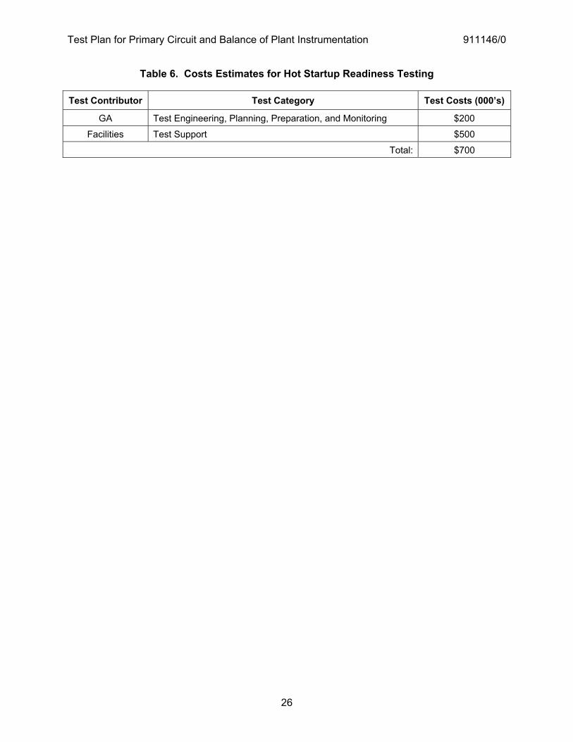
Table 6. Costs Estimates for Hot Startup Readiness Testing
Test Contributor Test Category Test Costs (000’s)
GA Test Engineering, Planning, Preparation, and Monitoring $200
Facilities Test Support $500
Total: $700

Test Plan for Primary Circuit and Balance of Plant Instrumentation 911146/0
27
7 OVERALL SCHEDULE FOR PCBOP DEVELOPMENT
An overall schedule for Primary Circuit and BOP Instrumentation development is provided in Figure 1.
Test
Pla
n fo
r Prim
ary
Circ
uit a
nd B
alan
ce o
f Pla
nt In
stru
men
tatio
n 91
1146
/0
28
TRL
Org
.A
ctiv
ityA
dvan
ce fr
om T
RL
3 to
4A
dvan
ce fr
om T
RL
4 to
5A
dvan
ce fr
om T
RL
5 to
6A
dvan
ce fr
om T
RL
6 to
7A
dvan
ce fr
om T
RL
7 to
83
� 4
GA
Eng
inee
ring
Des
ign
How
den/
BO
PC
oord
inat
e Te
st P
lann
ing
Ven
dor(s
)P
rovi
de B
ench
Sca
le D
ata
4 �
5G
AE
ngin
eerin
g D
esig
nG
A/V
endo
rTe
st P
lann
ing
Ven
dor(s
)P
rovi
de a
nd T
est E
quip
men
tTe
st F
acili
tyP
repa
ratio
n an
d C
ompo
nent
Tes
ting
5 �
6G
AE
ngin
eerin
g D
esig
nG
A/V
endo
rM
oist
ure
Ingr
ess
Pilo
t Sca
le D
evt T
estin
gH
owde
n/B
OP
Prim
ary
Circ
uit &
BO
P T
est P
lann
ing
GA
/Tes
t Fac
ility
Test
Con
figur
atio
n an
d Te
stin
g6
� 7
GA
Fina
l Des
ign
and
Pro
cure
men
t Spe
csV
endo
rE
quip
men
t Fab
ricat
ion
GA
/Ven
dor
Fact
ory
Acc
epta
nce
Test
ing
GA
/Wyl
eS
eism
ic T
estin
g7
� 8
GA
/Ven
dor
Equ
ipm
ent I
nsta
llatio
nG
A/N
GN
PH
ot S
tartu
p R
eadi
ness
Tes
ting
yr 5
yr 1
yr 2
yr 3
yr 4
yr 1
0yr
12
yr 6
yr 7
yr 8
yr 9
yr 1
1
Figu
re 1
. O
vera
ll S
ched
ule
for P
rimar
y C
ircui
t and
BO
P In
stru
men
tatio
n D
evel
opm
ent

P.O. BOX 85608 SAN DIEGO, CA 92186-5608 (858) 455-3000