Embed Size (px)
Citation preview

TEST REPORT ROTARY MINE COMB
Christopher Wanner
March 2005

2
INTRODUCTION .......................................................................................................................... 3
SYSTEMS DESCRIPTION............................................................................................................ 3
Rotary Mine Combing Tool........................................................................................................ 3
Host Vehicles .............................................................................................................................. 5
Farm Tractor ............................................................................................................................... 5
Construction Tractor ................................................................................................................... 7
Depth Monitoring........................................................................................................................ 8
Comb Monitoring........................................................................................................................ 8
TEST OBJECTIVES ...................................................................................................................... 9
RESULTS AND MEASUREMENTS.......................................................................................... 10
Calibration of Depth Shoes....................................................................................................... 10
Establishment of Rotor Speed................................................................................................... 11
Effective Width......................................................................................................................... 15
Combing Pattern ....................................................................................................................... 16
Simulated Minefield Combing.................................................................................................. 17
Results with the Farm Tractor .............................................................................................. 19
AT Mine Results (Farm Tractor) .......................................................................................... 19
Discussion of AT Mine Results (Farm Tractor).................................................................... 20
AP Mine Results (Farm Tractor) .......................................................................................... 21
Results with the Construction Dozer..................................................................................... 23
AT Mine Results (Construction Dozer)................................................................................. 24
AP Mine Results (Construction Dozer)................................................................................. 24
SUMMARY AND CONCLUSIONS ........................................................................................... 25
APPENDIX 1. Determination of Rotor Speed ......................................................................... 27
APPENDIX 2 Determination of Effective Combing Width..................................................... 36
APPENDIX 3 RANDOM MINEFIELD LAYOUT................................................................ 38
3
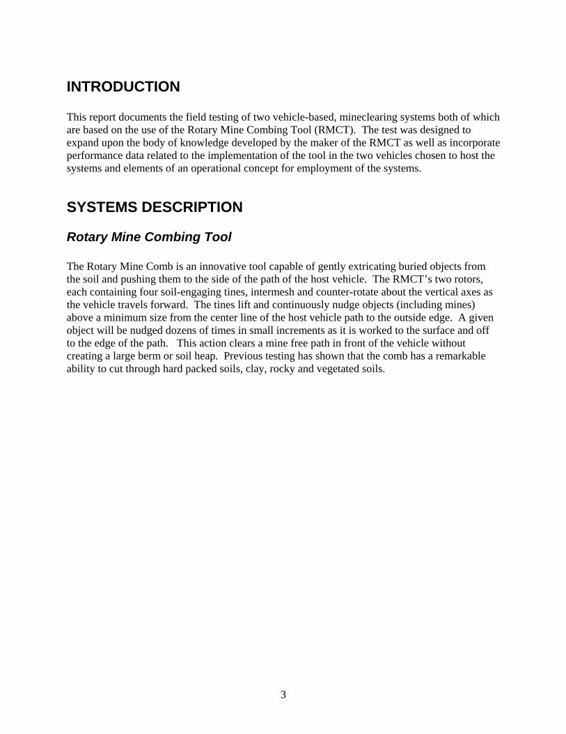
INTRODUCTION This report documents the field testing of two vehicle-based, mineclearing systems both of which are based on the use of the Rotary Mine Combing Tool (RMCT). The test was designed to expand upon the body of knowledge developed by the maker of the RMCT as well as incorporate performance data related to the implementation of the tool in the two vehicles chosen to host the systems and elements of an operational concept for employment of the systems.
SYSTEMS DESCRIPTION
Rotary Mine Combing Tool The Rotary Mine Comb is an innovative tool capable of gently extricating buried objects from the soil and pushing them to the side of the path of the host vehicle. The RMCT’s two rotors, each containing four soil-engaging tines, intermesh and counter-rotate about the vertical axes as the vehicle travels forward. The tines lift and continuously nudge objects (including mines) above a minimum size from the center line of the host vehicle path to the outside edge. A given object will be nudged dozens of times in small increments as it is worked to the surface and off to the edge of the path. This action clears a mine free path in front of the vehicle without creating a large berm or soil heap. Previous testing has shown that the comb has a remarkable ability to cut through hard packed soils, clay, rocky and vegetated soils.

4
Figure 1. Rotary Mine Combing Tool
A key parameter in the performance of the tool is the “tine increment”, which is the distance the vehicle travels forward between any two successive passes of the tines. Generally this must be kept small enough to avoid allowing the smallest objects desired to be excavated from slipping through the space between the pass of one tooth and the pass of the next one. As a practical matter it is speculated that keeping the tine increment smaller than 1/3 the diameter of the mines being cleared will permit the tines to always engage the mines from the rear. Figure 2 shows the vehicle speed as a function of the chosen rotor speed and chosen tine increment. Because the RMCT requires a reasonably large target to engage as the combing action occurs, it is intended for use in clearing antitank mines and not antipersonnel mines. The weight of the RMCT is 3160 KG, and the combing width is 3.5 meters.

5
MAXIMUM TRACTOR SPEEDS ALLOWABLE
0
100
200
300
400
500
600
700
800
0 5 10 15 20 25 30 35Rotor Speed RPM
Me
ters
Pe
r H
ou
r
2 Centimeter Increment
4 Centimeter Increment
6 Centimeter Increment
8 Centimeter Increment
10 Centimeter Increment
Figure 2. Tractor Speed vs. Rotor Speed at Selected Tine Increments
Host Vehicles The comb has been integrated into two very different host vehicles for these tests. Part of the test objectives is to document the common capabilities of the RMC tool; another part of the test objectives is to contrast the strengths and weaknesses of each particular implementation. No special survivability or protective features are present in either vehicle at this point in the development.
Farm Tractor The first vehicle configured is the 115 kW, John Deere 7820 farm tractor. The comb attaches to the standard three point hitch on the rear of the tractor, and no special interface is required. The comb is driven from the standard PTO shaft available on the tractor. The mechanical drive internal to the comb includes both gears and chain drives in series. Two different sized chain drive sprockets and two gear box ratios are provided, which along with the tractor selectable 540 RPM and 1000 RPM PTO drive speeds gives 8 different, full power rotor speeds ranging from 9 to 34 RPM.

6
Figure 3. RMCT On Farm Tractor
The tractor is driven backwards when combing in order to clear the vehicle path. The tractor is equipped with a regulated and infinitely variable mechanical transmission which allows precise setting and control of the vehicle speed independent from the setting and control of the engine speed. This allows the engine to supply high power to the comb drive through the PTO while traveling slowly as required by the “tine increment” considerations. The range of tractor speeds required can be bounded by considering a conservative minimum of one quarter of the diameter of the smallest toe popper mine being combed at the lowest rotor speed available (1.5 cm and 9 RPM respectively). These requirements result in a vehicle speed of 32 meters/hour. The upper bound can be established by considering a risky maximum of one half of the diameter of the largest AT blast mine being combed at the highest rotor speed (16 cm and 34 RPM respectively). These requirements result in a vehicle speed of 1305 meters/hour. Practical considerations and experience with the RMC tool has more narrowly focused vehicle operations in the range from 100 meters/hour to a high of 380 meters/hour for most mines and clearing situations of interest. Although the comb weight is well within the 6500 KG limit for the three point hitch, its front-to-back length of 2.5 meters places a heavy cantilevered load on the tractor. The manufacturer of the RMCT has equipped the system with skid shoes to provide depth control and lateral stability, and to support the implement weight when combing. The skids however are vulnerable to mine blast and part of the objective of the test was to document how well the operator and system can control the comb without using the skid shoes. As is common in three point hitch configurations, the raising of the hitch is hydraulically driven; however the lowering is driven solely by gravity. Further, the angle the hitch and comb make with respect to the plane of vehicle travel is mechanically fixed. It can be adjusted between passes, but during a combing run, the RMCT

7
will only be exactly on parallel plane with the vehicle at one depth. If ground undulations and terrain discontinuities are considered, the ability of the operator to make adjustments would be a desirable, yet unavailable and untested feature of the Deere vehicle.
Construction Tractor The second vehicle configured is the 77 kW, Liebherr 712 tracked, crawler tractor. The comb attaches to a special mounting built to interface with the standard front dozer blade lifting arrangement. The comb is driven from a hydraulic motor built into the interface. Power for the hydraulic motor is supplied from an 80 kW hydraulic system with a separate diesel engine mounted on the rear of the tractor. Both the hydraulic motor and the supply pump have electrically controlled, continuously variable displacements, giving rotor speed control beyond the ranges of interest discussed above in the farm tractor description. The tractor is equipped with a hydrostatic drive system. This gives the vehicle unregulated but continuously variable speed control, set independently from the vehicle engine throttle. Because the speed is not regulated or monitored, operation at the very low speeds required by the comb does require the constant attention of the operator to keep motion going and controlled. Having the capability to “set and forget” the vehicle speed is a desirable yet unavailable feature of the Liebherr vehicle.
Figure 4. RMCT on Construction Dozer
In contrast to the Deere implementation in which the comb floats on the three point hitch, the mechanical interface rigidly fixes the comb to the tractor. The comb is both lifted and driven into the ground hydraulically. In addition, the pitch of the comb relative to the plane of travel is controllable and adjustable by the operator “on the fly”.

8
Depth Monitoring The skid shoes which the RMCT manufacturer supplies for depth control are weight bearing devices located in front of the comb. The shoes’ ground pressure over uncombed soil makes them vulnerable to mine detonation. Both of the vehicles on which these tests were conducted are larger, more stable platforms than the New Holland 160/90 tractor on which the original RMCT development and testing was conducted. These tests were conducted with the operator exercising control over the combing depth on the basis of feedback from a depth-indicating shoe tracking the ground surface behind the combs.
Figure 5. Hinged Depth Shoe.
This change in depth control was designed to allow the forward mounted, weight bearing skid shoes to be eliminated from the system. Placing the indicator behind the comb removes the threat of mine damage and vegetation interference with the operation of the shoe. However, the comb’s shearing of the soil into a more fluid medium, and its creation of large clods or sod chunks provides a less readable surface to sense. The shoe implemented for these tests is intended to provide moderate ground pressure which sinks the shoe 0-5 centimeters into the sheared soil under most conditions, but allows it to cut through soft discontinuities. The shoe is attached to a depth indicating rod which has alternately white and black bands which can be calibrated to give a rough indication of current combing depth. The task of the operator with respect to controlling the depth amounted to keeping the indicating rod within one of these 5 centimeter black or white bands.
Comb Monitoring The workspace in front of the comb is monitored with an inexpensive video camera mounted in the center of the comb. A wide angle lens captures the full width of the comb from the centerline to point of tangency with the left and right edges of the cleared path. The view provided looks nearly straight down, centered 30 centimeters to the front of the comb. About 1/3 of the rotor interior diameter is visible; however none of the area beyond the right or left edges of the rotors

9
is visible, nor is any of the rear portion of the rotor arcs (closest to the tractor). A second camera also mounted on the comb is fixed on the depth indicating rod. Although the operators of both systems are able to see the rods from the vehicle cab, the rod camera was evaluated for possible inclusion in a future remote control implementation of the system. A third, external camera was available at the remote station where the video signals were received and monitored. The external camera, like the rod camera, was evaluated for general site monitoring in support of future remote control developments.
Figure 6. Approximate Camera Field of View
TEST OBJECTIVES Previous testing with the Rotary Comb has served to characterize many important performance aspects of the Comb. Moving beyond previous test limitations, inclusion of the recent system improvements and additions and expansion of test objectives have added to the body of experience with the Rotary Comb. All evaluations were conducted through controlled field testing at army ranges. Test Objectives: Objective 1: Accurately test and evaluate the detonation risk of various mine types when processed with the Rotary Mine Comb. Objective 2: Assess whether various sized mines can be excavated and visually detected with human monitors watching comb-mounted video camera output. Objective 3: Compare and evaluate the ability of the system operator to perceive and control the operation of the Rotary Mine Comb when rigidly mounted to a construction style tractor versus the agricultural tractor 3 point hitch it was designed for. Objective 4: Further define the ability of the Rotary Mine Comb to excavate, expose, and clear various sized landmines from less than ideal soil conditions. Objective 5: Contrast the relative strengths and weaknesses of the each of the vehicle configurations tested with respect to the other.

10
Objective 6: Evaluate the utility of the Greenstar tracking system for assisting a comb operator to set up and maintain a set of parallel cleared paths. Objective 7: Evaluate the optimum operating parameters (depth, vehicle speed, comb speed etc.) as a function of mine type, soil conditions, and other environmental/threat factors. Objective 8: Quantify the operating characteristics of the Rotary Mine Combs.
RESULTS AND MEASUREMENTS
Calibration of Depth Shoes The depth shoes installed on the two vehicles give a rough indication of the depth at which the comb is penetrating at any given moment. Because the system is trailing behind the movement of the comb, error is introduced by the degree to which the elevation of the surface of the tilled soil differs from the untilled soil. This is estimated from observation to be plus or minus three centimeters; however occasional objects in the soil and clumps of sod can alter the surface elevation temporarily but significantly. In addition the pressure of the mechanical shoe penetrates the tilled soils from 0-10 centimeters depending upon soil strength and amount of total shoe deflection (the shoe generates more pressure when sensing deeper comb penetrations). The variability of this penetration adds additional error. Because of these effects, the performance and calibration of the shoes will depend on local soil and vegetation cover conditions. In order to calibrate the indicating rods and assess the variability in the rod indications, each of the systems was driven with the operator maintaining the depth shoe at the bottom of a specific depth band on indicating rod attached to the shoe. The combing action was halted with the comb at the operating depth corresponding to the band of interest. Test personnel excavated around the teeth by hand and the elevation was measured of the tine tips relative to the adjacent, untilled soil surface. The accuracy of the indicated depths with the measurements taken here are estimated to be no better than plus or minus 5 centimeters. Note that the shoes are mounted at an arbitrary height on each frame and the indicated depths (given in “bands”) have no relationship or comparison between one vehicle and the other vehicle. Also note that the maximum penetration of each tine as it travels around the circle depends on the pitch of the comb as well as the height of the hitch interface. The depth values will only match the measured values (taken at the “front to back” midpoint of the comb) if the comb is parallel with the ground. Table 1 gives the depth measured for each indicating band for the construction tractor, and table 2 gives the measured depths for the farm tractor. It is difficult to estimate the error associated with relying on the tabulated values to define the combing depth; however, the bands were the primary means the operators used to control the depth over the course of the testing. With the exception of the entry of the comb into the soil and initial establishment of the shoe moving from un-tilled soil into the tilled soil, the indicating rod provided a reasonable, repeatable indication of depth as compared to depth estimates made by ground personnel observing the testing over 40 hours of operation.

11
Liebherr 712 Dozer
Actual Measured Depth (cm) Indicated Depth Clay Soil Sand
Band 0 11 17 Band 1 20 20 Band 2 29 24 Band 3 33 38 Band 4 38 42 Table 1. Depth as Measured by Indicator Rod on Dozer John Deere 7820 Tractor
Actual Measured Depth (cm) Indicated Depth Clay Soil Sand
Band 0 8 - Band 1 22 23 Band 2 24 27 Band 3 46 48 Table 2. Depth as Measured by Indicator Rod on Tractor
Establishment of Rotor Speed A key defining parameter in the operation of the Rotary Mine Comb is the maximum rotational speed allowable. As tine speed is increased, so is the potential for structural damage to mines encountered, and quite probably the risk of mine detonation. Properly assessing the maximum allowable rotor speed is important for both managing the risk of detonating AT mines and for defining the overall clearance rate with the comb. AT mine detonation risk as a function of rotor speed was not directly measured; however, observations were made of structural damage to mine AT bodies at varying rotor speeds. These tests were conducted using surrogate AT mine bodies (see Fig. 7) buried in both sand and unvegetated clay.

12
Figure 7. Mine Surrogate
The surrogate mine bodies are constructed from sand filled, 20 gauge, low carbon steel shells, generically representing large antitank landmines. The test lanes were prepared as diagrammed in figure 8.
40 Meters
1 M
0.8 M
10 Meters
10 Centimeter Depth30 Centimeter Depth20 Centimeter Depth
Figure 8 Test Lane for Rotor Speed Trials
Each test lane was combed using a fixed tine increment of 4 centimeters. One of 4 different rotor speeds was used for each group of 12 mine surrogates shown in figure 8. Thus both rotor speed and vehicle speed increased with each group of 12 surrogates encountered. The test rotor speeds used were 12.1, 18.5, 25.7, and 34.3 rpm, which correspond to four of the eight available full power PTO speeds from the farm tractor. Data for these combing tests at varying rotational speeds is found in Appendix 1. Table 3 summarizes the damage imparted to the AT mine surrogates buried in sand for each of the burial conditions and rotor speeds used in these tests. Table 4 summarizes the damage for these same conditions with mines buried in compacted clay. Although the small numbers of test objects at

13
any one condition are reflected in a few minor paradoxical results, it is no surprise that increases in soil strength, rotor speed, and burial depth each independently lead to increased physical damage to the surrogate mine bodies as they are combed to the surface. The sand used for the tests described in table 3 is very clean, homogeneous beach sand offering little resistance to movement of objects. Even at the highest speeds damage to the surrogate bodies was acceptable for all but those buried at 30 centimeters, which sustained damage considered marginal from the standpoint of predicting detonation risk. The higher rotational speeds did, however, sling sand in all directions, and many of the surrogates were reburied after having been excavated and cleared from the tractor path. In soils of similar composition or strength, the top speed in the range from 26-34 rpm is recommended as the limiting speed on the basis of considerations of mine damage unless mines are expected to be found below the 20 centimeter level. In cases of burial depths below 20 centimeters, speeds in the range from 18 to 26 rpm may be considered as the upper limit.
Burial Depth Rotor Speed 10 centimeters 20 centimeters 30 centimeters
12 RPM Surface scratches only
Minor dents only Minor dents only
18.5 RPM Surface scratches only
Minor dents only Minor dents and slight structural buckling
25.7 RPM Surface scratches only Minor dents Moderate dents and
moderate structural buckling
34.3 RPM Minor dents and slight structural buckling
Minor dents and slight structural buckling
Moderate dents and moderate structural buckling
Table 3. Summary of damage to AT mine surrogates buried in sand In contrast, the clay soil results reflect a much tougher challenge. The surrogates were buried as prescribed and the test lane was compacted with a vibratory roller to produce a very hard, unyielding medium. The farm tractor used for these tests did have some difficulty in achieving and maintaining the desired combing depth. This is reflected in the results at 30 centimeters burial depth where many of the test objects were speared by the tines rather than being lifted to the surface. With no apriori knowledge of detonation risk, subsequent test expectations place a conservative lower limit of risk at the level of stress producing minor dents and slight case buckling. An upper limite of risk was established at conditions producing moderate dents and moderate case buckling.

14
Figure 9. Example of Surrogate with Moderate Dent and Slight Case Buckling
In setting limits for other tests or field usage, these ranges would be adjusted up or down in consideration of soil strength and expected mine burial depth. Thus for non-compacted clay, such as made up the test area used for the simulated minefields later in the test program, a range of 12-18 rpm was predicted to show acceptable results for burial depths up to 20 centimeters and marginal to unacceptable results for any deeply (>20 cm) buried mines.
Burial Depth Rotor Speed 10 centimeters 20 centimeters 30 centimeters
12 RPM Moderate dents and structural buckling
Moderate dents and slight structural buckling
Large dents and significant structural buckling
18.5 RPM
Minor dents and slight structural buckling
Large dents and moderate structural buckling
Large dents and significant structural buckling and case rupture
25.7 RPM Moderate dents and slight structural buckling
Large dents and significant structural buckling
Large dents and case rupture
34.3 RPM Moderate dents and slight structural buckling
Large dents and moderate structural buckling
All surrogates impaled on comb teeth or shredded
Table 4. Summary of damage assessments on AT mine surrogates buried in compacted clay

15
Effective Width The nominal width of the Rotary Comb is 3.1 meters; however, because the teeth project along a tangent to the rotor circumference, the actual span reached by the tines is approximately 3.5 meters. In reality, however, there is a finite travel distance a buried object must be pushed laterally in order for that object to move upward and break the ground surface and become visible. Buried objects which are encountered near the outside edges of the combed path do not have the requisite length of engagement with the comb’s tines in order to break the surface before they are pushed aside on a relatively short trajectory as the comb passes them by. Although mines in this situation may be considered cleared from the vehicle path, they have not met the program requirement of being made visually detectable. In order to assess the “effective width” over which the comb is capable of making buried objects visible, a test lane was constructed with mines buried at one of 8 distances or offsets from the lane centerline (beginning at 85 cm offset and continuing at 10 cm increments up to 155 cm). Each mine was buried at 20 centimeters depth to the bottom of the mine. Table 5 summarizes the observations made when the lane was combed with the centerline of the RMCT passing down the centerline of the test lane.
Distance of Mine Offset from Centerline
Observation (All Mines Initially Buried 20 cm)
155 centimeters Observers could clearly perceive the movement of the mines below
the surface / Mines never became visible above the surface.
145 centimeters Observers could clearly perceive the movement of the mines below
the surface / Mines never became visible above the surface.
135 centimeters Observers could clearly perceive the movement of the mines below
the surface / Mines never became visible above the surface.
125 centimeters Observers could clearly perceive the movement of the mines below
the surface / Mines never became visible above the surface.
115 centimeters Observers could clearly perceive the movement of the mines below
the surface / Mines became partially visible above the surface
105 centimeters Observers could clearly perceive the movement of the mines below the surface / Mines became fully visible above the ground surface
95 centimeters Observers could clearly perceive the movement of the mines below the surface / Mines became fully visible above the ground surface
85 centimeters Observers could clearly perceive the movement of the mines below the surface / Mines became fully visible above the ground surface
Table 5. Summary of Test Mine Visibility

16
As noted in the table, all mines, regardless of initial position, produced a distinct jerky vibration in the comb and at the ground surface that was observable both to ground observers and to a lesser extent, the camera observers. In order for a mine to be made at least partially visible above the ground surface, it must be located within 115 centimeters from the lane centerline, giving an effective width of 2.3 meters in heavy clay for mines buried 20 centimeters. Presumably, deeper mine burials would result in a narrower effective lane width, and shallower burials would result in a wider effective lane width.
Combing Pattern The development of an effective pattern for combing an area is a necessary requirement. Prior testing had led to the conclusion that a path as diagrammed in figure 10 is required to keep balanced draft and side shifting forces on the comb. As diagrammed the comb is always either engaging a full width cut of bank condition soil or a center “slice” of bank soil with equal strips of previously tilled soil at the edges of the cut.
3
5
2
4
6
7
Initial Pass
Figure 10. Alternating Combing Pattern
Without this method, experience has shown the comb will wander inexorably to the softer soils in the previously tilled area despite the operator’s best efforts to the contrary. Planning for proper overlap from pass to pass required consideration of the effective lane width as measured in the previous test. In addition consideration must be made of the placement of the wheels or tracks of the host vehicles with respect to previous passes with the comb. Figure 11 diagrams the various widths associated with the tractor as it makes a combing pass. The center line spacing from adjacent passes must be less than the effective lane width if all mines are to be made visible. The uncombed gap left between alternating lanes which is combed last must either be wider than the outer track width, or must be narrower than the inner track width in order to keep both tracks either both on combed soil or both on uncombed soil. Leaving a pass-to-pass gap wide enough for the outer track width will result in lane spacings of 293 centimeters which is too wide for the effective lane width consideration. Leaving a pass-to-pass gap narrow enough for

17
the inner track width to straddle will result in permitted lane spacings of less than 232 centimeters. 210 centimeter lane spacings were chosen for the simulated minefield clearance tests. This spacing left gaps of 70 centimeters which were taken out on the odd numbered passes as diagrammed in figure 10.
Inner Track Width 114.0
Outer Track Width 236.0
Effective Lane Width 230.0
Tilled LaneWidth 350.0
Figure 11. Lane Widths Associated with Tractor and Comb
Simulated Minefield Combing Field trials with the Rotary Mine Combs culminated in tests in which the combs covered areas seeded with mines randomly placed. The purpose of this phase of testing was to prove that all of the elements of control, efficiency, perception, and procedure can be put together into a single, workable concept for minefield clearance. Each vehicle was used to comb a 40 meter square containing 50 fuzed, AT mine simulants, 50 fuzed Type 72 AP mine simulants, and 50 fuzed PMN mine simulants as shown in Appendix 3. The mines were randomly assigned to one of three burial depths: 10 centimeters, 20 centimeters, or 30 centimeters measured to the bottom of the mines. The mock minefields were constructed six months prior to the test and seeded with grass in order to let the earth settle and vegetation grow. An external monitoring station was placed 15 meters beyond the end of the minefield border. The monitoring station was equipped with a mast mounted pan and tilt camera and receivers/monitors to allow observers to watch the comb-mounted cameras.

18
Figure 12. External Monitoring Station
The combing was conducted with an operator in the seat of the vehicle, two observers watching the video monitors for evidence of mines, and one observer walking adjacent to the comb. The camera observers notified the operator and ground observer when they perceived a mine was unearthed and made visible in the field of view of the comb-mounted cameras. The combing was suspended while the ground observer investigated the object declared by the video observers. If the object was found to be a mine, the ground observer checked the fired/not fired status without disturbing the mine’s location. After the combing resumed, the ground observer maintained awareness of each mine and recorded its fate as “cleared” if it was pushed aside and “not cleared” if it failed to clear the width of the vehicle tracks. Mines which were visible to the ground observer but not to the video observers and mines which the ground observer believed to have been cleared but not exposed which remained within the overlap zone of the adjacent pass were left in place until all passes capable of reaching them were completed. The target tine increment for these tests was 2 centimeters, chosen to provide the comb a reasonable opportunity to engage the 8 centimeter diameter of the smallest test mine (Type 72). The target rotor speed for these tests was 18.5 RPM; chosen to allow a reasonable compromise between forward tractor speed and damage to the mine bodies from high rotor speed. At this combination of tine increment and rotor speed, a forward vehicle speed of 90 meters per hour is required. At this speed the tractor requires just less than one half hour to cross the minefield. The rotor speed of 18.5 RPM could be expected to produce some risk to the AT mines buried at 20 centimeters and significant risk to the mines buried at 30 centimeters, judging by the damage done to the surrogate bodies in the earlier tests.

19
Results with the Farm Tractor The time required to completely comb the 2000 square meter minefield and boundary areas was 8.5 hours. Including maintenance and mine investigation and recovery time the work required two full working days (16 hours) to complete. Seventeen passes were required to completely cover the minefield, and the average speed per pass was right on the target of 90 meters per hour with all passes falling within 20% of the target speed. The target depth combed over the duration of the test was 2.5 bands on the indicating rod, equating to 35 centimeters. No independent measure of the depth achieved was available. The average lane-to-lane spacing at the test conclusion turned out to be a little greater than desired at 235 centimeters versus the maximum 230 planned on the basis of the observations made in reference to the effective width.
AT Mine Burial Depth Event 10 Centimeters 20 Centimeters 30 Centimeters All Depths
Mine Detected by Camera Observers
100% 78% 78% 43/50
Mine Cleared from Vehicle Path
100% 100% 73% 43/47
Mine Excavated without Detonating
100% 100% 69% 43/48
Table 6. AT Minefield Results / Tractor
AT Mine Results (Farm Tractor) Table 6 gives the outcome of various measures of performance for the tractor mounted comb against the AT mines buried in the random minefield. The total mine count for the minefield is given in the right hand column, with the results further separated by depth to the bottom of the mines and reported as percentages in the middle three columns. To the maximum extent possible, each possible event was recorded as an independent measure of effectiveness; thus mines which triggered upon contact with the comb were left in place and given the chance to clear in order to extend the data collection to the greatest extent. It was not always possible to independently report the fate of each mine with respect to each of the three measures. Some of the mines reported as “detonated”, for example, were completely ruptured and therefore unable to continue the test to see if the mine body would have been cleared. As a result the total targets reported in the right column are different for each of the events being reported.

20
Discussion of AT Mine Results (Farm Tractor) The dependence of the fuze triggering on the depth of burial in table 6 is not surprising. The increasing damage observed in the surrogates reported in the investigation of rotor speed with increased depth is consistent with these results; see figures 13-15.
Figure 13. AT Test Mines Recovered from 10 cm Burial
Figure 14. AT Test Mines Recovered from 20 cm Burial

21
Figure 15. AT Test Mines Recovered from 30 cm Burial
Although it is not surprising that the more deeply buried mines created more difficulty in clearing, observations of the process were that all mine bodies were excavated and pushed to the side of the path, and no AT mines are believed to have passed under the comb or slipped through gaps in the tines. Each of the 4 mines of row 2 in table 6 that failed to clear was unable to disengage from the push of the tine. These mines were carried around to the rearward part of the arc and dropped in the tractor’s path. If there is a “preferred way to fail to clear” this was it because mines handled (and dropped) in this manner would be easily visible to the camera and ground observers prior to creating any risk to the vehicle. The 7 mines which the camera observers failed to detect are each believed to have been engaged near the outside edges of the comb. As discussed the camera field of view barely covers the full comb width, and objects moving along the forward face of the tine arc were difficult to perceive when they were within half a meter of the outside edge of the comb. The mines buried at 10 centimeters nearly instantly broke the surface when engaged and became visible. As discussed in the test of the effective lane width, mines buried 20 and 30 centimeters are pushed a short distance before becoming visible. Mines breaking the surface in the regions near the edges of the camera view simply were not perceptible to the observers. Compounding this shortcoming of the camera system was the overly wide (235 centimeters) lane to lane spacing realized on the test. These effects are believed to be responsible for the difference in the fraction of mines detected by the observers for the mines buried at 10 centimeters and those buried at 20 and 30 centimeters.
AP Mine Results (Farm Tractor) Table 7 gives the outcome of various measures of performance for the tractor-mounted comb against the AP mines buried in the random minefield. The total mine count for the minefield is

22
given in the right hand column, with the results further separated by mine type and reported as percentages in the middle two columns. In contrast to the results of the AT mines, there was little chance of any AP mines being cleared by the comb, and this measure was not reported. In addition the success rates in each of the categories measured was much lower and more randomly realized with the AP mines versus the AT mines. With the low numbers of mines buried at any given depth, the results are much more affected by random chance, and therefore the totals are only separated by mine type and not by depth. A new category of results is included to account for the fact that there is some value in the result where there were AP mines which the camera observers failed to detect and the comb failed to clear, but which were excavated and left visible in the lane. The mines classified as “Detected or Exposed on Lane Inspection” includes all mines either seen by the camera observers or left visible after the comb passed.
AP Mine Type Event PMN Type 72
Combined Count
Mine Detected by Camera Observers
46%
48% 47/100
Mine Detected or Exposed on Lane Inspection
68% 64% 66/100
Mine Excavated without Detonating
23%
61% 27/65
Table 7. AP Mine Results / Tractor Just under half of the AP mines buried in the random minefield were detected by the camera observers. The concentration required to achieve this result was intense because the AP mines were generally visible only for 1 pass of the tines. The AP mines fit well within the small groove created by the path of the tines. Generally they would be carried on a small charge of soil in front of one of the tines and then “dropped” when reaching the rear side of the arc. Shadows and varying light conditions under the comb and in the grooves created by the tines created local spots easily capable of concealing an AP mine from view of the comb camera. Overcoming these shadows, dealing with rocks the size of the mines, and focusing on the full comb width while looking for a puck-sized object proved to be an insurmountable challenge for the camera observers. An estimated 10-20% of the AP mines declared by the camera observers were quickly reburied and required some manual excavation by the ground inspection team in order to retrieve. Combining the mines detected by the camera observers with the mines not detected by the camera observers but left exposed in the combed lanes allowed recovery of 2/3 of the mines buried with one pass of the rotary comb.
23
The fraction of AP mines triggered in the combing process is the only measure in which the results varied significantly depending on mine type. Almost 80% of the PMN mines were fired by the comb, while 40% of the type 72 mines fired. Although the single pass results reported in table 7 are less than hoped for, a variety of possibilities exists for additional testing. For example, with the AT mines removed in the first pass of a multipass process, subsequent passes could be run much faster with higher rotor speeds to build required levels of clearance confidence against the AP mines. If the preponderance of mines encountered are toe popper style AP blast mines, the fraction of detonations becomes an asset rather than a liability with a combined rate of finding or detonating the mines approximately 80% per pass.
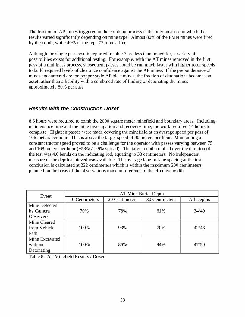
Results with the Construction Dozer 8.5 hours were required to comb the 2000 square meter minefield and boundary areas. Including maintenance time and the mine investigation and recovery time, the work required 14 hours to complete. Eighteen passes were made covering the minefield at an average speed per pass of 106 meters per hour. This is above the target speed of 90 meters per hour. Maintaining a constant tractor speed proved to be a challenge for the operator with passes varying between 75 and 168 meters per hour (+58% / -29% spread). The target depth combed over the duration of the test was 4.0 bands on the indicating rod, equating to 38 centimeters. No independent measure of the depth achieved was available. The average lane-to-lane spacing at the test conclusion is calculated at 222 centimeters which is within the maximum 230 centimeters planned on the basis of the observations made in reference to the effective width.
AT Mine Burial Depth Event 10 Centimeters 20 Centimeters 30 Centimeters All Depths
Mine Detected by Camera Observers
70% 78% 61% 34/49
Mine Cleared from Vehicle Path
100% 93% 70% 42/48
Mine Excavated without Detonating
100% 86% 94% 47/50
Table 8. AT Minefield Results / Dozer

24
AT Mine Results (Construction Dozer) The results of the various outcomes are reported in table 8 as functions of the burial depth to the bottom of the mines. As with the tractor mounted comb, the camera field of view used to monitor the workspace of the rotors was not large enough to perceive mines unearthed near the edges of the lane. AT mines engaged within a span approximately 2 meters wide around the centerline were easily identified by the camera observers, but those outside this span were frequently not identified. The relatively large number of AT mines missed by the camera observers is attributed mainly to random chance engaging mines in the impaired vision zones of the monitoring system. The mines that failed to clear from the vehicle path were with one exception due to the mine not disengaging from the tine at the comb edge and subsequently being carried to the back side of the arc and dropped. One mine did slip between successive passes of the tines and made it to the interior of the rotor. The overall fuze triggering rate with the dozer-based RMC was a little better than the test results with the farm tractor based system. This has been attributed to the greater combing depth realized with the dozer perhaps fracturing the soil earlier in the contact interval between tine and mine. In addition partial rainy conditions during the test of the dozer based RMC served to soften the soil and provide a more yielding medium through which to move the mines to the surface.
AP Mine Results (Construction Dozer)
AP Mine Type Event PMN Type 72
Combined Count
Mine Detected by Camera Observers
50%
26% 33/100
Mine Detected or Exposed on Lane Inspection
74%
48% 61/100
Mine Excavated without Detonating
48%
54% 31/61
Table 9. AP Mine Results / Dozer As with the farm tractor-based results, the overall chances of any given AP mine being favorably included in one of the categories reported in table 9 is much more subject to random chance than with the AT mine results. About one third of the AP mines were excavated and witnessed by the camera observers. This was slightly lower than reported with the farm tractor-based system. Possible explanations for the difference are the generally lower levels of ambient light during the overcast and rainy conditions in which these results were collected. In addition, the variability in

25
the dozer speed discussed above would be expected to provide shorter and varying intervals during which these mines were visible to the observer. Nearly two thirds of the AP mines were either detected by the observers or left exposed in the soil after a single pass of the rotary comb and about one half of the AP mines recovered had “fired” in the process. Both of these results are consistent with the tractor based tests.
SUMMARY AND CONCLUSIONS The main purpose of defining a working concept for using the rotary comb was met through the tests performed. The concept of using remotely located observers to monitor the excavation of the test mines was proven although the overall performance was less than desired and additional adjustment and modification to elements of the system are required. Each of the individual test objectives was explored to varying degrees with the exception of using and evaluating the John Deere Greenstar GPS navigational aid in steering and navigating the combing rows across the field. The Greenstar has an advertised pass-to-pass accuracy of 4 inches with respect to indicating the vehicle position relative to planned parallel paths through the minefield. Unfortunately the visual cues designed to assist the operator in maintaining a desired path were only operable with the vehicle traveling in the forward direction. With the comb rear-mounted and the tractor driven backwards, the feedback offered by the system was of no assistance. Nevertheless, the ability of the operators to perceive and maintain a straight path with consistent overlaps was easily achieved by the on board operators. Following required paths during remote operation (as is envisioned for this system) is still believed to require some form of navigational aid, and use of the Greenstar system will not be the solution for the backward driven farm tractor. In meeting and attempting to cover the simultaneous objectives of performing low-detonation-risk excavation of antitank mines and performing small-tine-increment excavation of antipersonnel mines we perhaps chose a rotational speed a little on the high side at 18.5 rpm. The AP mines proved to be too small to reliably excavate and perceive on the video monitors. Overall about 40% of the AP mines were detected, and 64% were excavated and exposed. With a 2 centimeter tine increment used to try and capture these small mines, we were unable to achieve an acceptable result. Expected improvement by performance at even finer tine increments is predicted to be modest. In order to complete the test at a reasonable clearance rate, a high rotor speed was chosen relative to the predicted risk of deeply buried, AT mine detonation in clay soil. Overall 100% of the AT mine buried 10 centimeters were safely excavated, but only 93% and 82% were safely excavated at 20 and 30 centimeters respectively. This suggests dropping the rotor speed when excavating in cohesive or rocky soil at depths below 10 centimeters in order to improve (decrease) the chances of causing the mines to trigger. Because it does not appear to be feasible to excavate AP mines with high reliability, the small tine increment used for these tests can most likely be doubled or more without loss of clearance efficiency for AT mines. This will keep the clearing rate at 100 meters per hour or possibly higher even with the reduced rotor speed.

26
Damage to the mine casings sustained in the combing process is a reliable predictor of risk for triggering excavated mines. This suggests using surrogate mine bodies emplaced in local conditions, not only as a training aid but as a diagnostic for prescribing operational parameters for the comb (depth of cut, rotor speed) which are tailored to the local environmental conditions. No mines were triggered in these tests which did not have at least moderate structural buckling of the casing in the correspondingly emplaced AT surrogate at the chosen rotor speed. The condition of long buried mines and the design trigger pressure will be additional variables in determining how roughly we may treat a given mine type in the excavation process, but examining damage to surrogate casing provides a useful starting point. The picture quality and ability of the observers to perceive AT mines appearing in the middle of the field of view of the on board camera were excellent. The coverage and field of view provided by the onboard cameras of the workspace immediately in front of the comb was inadequate to realize the full potential of using observers to detect mines as they are excavated. As discussed, mines engaged near the outer 15%-20% of the path were generally not perceptible to the observers. Overall 86% of the AT mines buried at 10 centimeters were visually detected, 78% buried at 20 centimeters, and 69% buried at 30 centimeters. The chance of significantly raising these efficiencies to the high 90’s is believed excellent with the use of two cameras more fully covering the path and adjacent strips. As discussed the effective path width for which the comb is capable of making mines visible is reduced about 30% from the physical width of the span of the rotors due to the need for mines to be nudged multiple times before becoming visible on the surface of the ground. Mines near the edges of the combed path become disengaged with the comb before they fully surface. At 2.3 meters effective width, approximately 1.1 meters of overlap from pass to pass was required. Although not tested here, the alternating pattern of figure XX is believed to be needed to keep side forces and unbalanced draft forces on the comb from pulling the farm tractor off course. Differences in performance between the two host vehicles produced some variation in the results that are overall judged to be modest. The farm tractor provided a more tightly controlled speed from which to comb. This may account for better performance of the observers detecting the AT mines from the farm tractor than from the construction dozer (88% versus 69% over all conditions). Operators of the dozer reported having to devote significant attention to maintaining forward motion at appropriate speed during the tests. Some form of additional speed control for this vehicle is recommended to relieve the operator of this task. The construction dozer provided a more stable platform capable of reaching greater depths. This may partially account for the better performance of the dozer mounted comb in excavating AT mines without triggering them (94% versus 89% over all conditions). The added directional stability of the dozer may allow the system to make adjacent, overlapping passes with out having to perform the alternating pattern of figure XX. The inability of the operator to adjust the pitch of the comb on the farm tractor was not a significant burden in the test environment but could become a shortcoming in minefields with sharp terrain features and undulations less than the length of the vehicle in spacing.

27
APPENDIX 1. Determination of Rotor Speed
Data Sheets
28
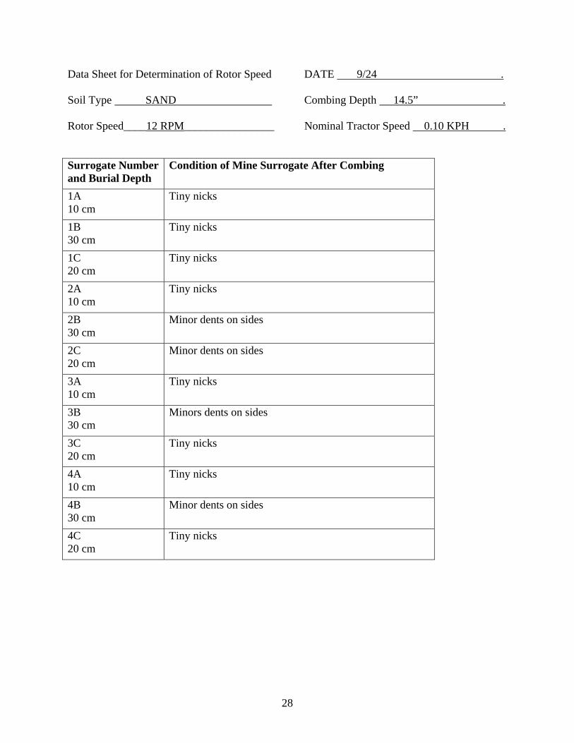
Data Sheet for Determination of Rotor Speed DATE 9/24 . Soil Type SAND Combing Depth 14.5” . Rotor Speed____12 RPM________________ Nominal Tractor Speed 0.10 KPH . Surrogate Number and Burial Depth
Condition of Mine Surrogate After Combing
1A 10 cm
Tiny nicks
1B 30 cm
Tiny nicks
1C 20 cm
Tiny nicks
2A 10 cm
Tiny nicks
2B 30 cm
Minor dents on sides
2C 20 cm
Minor dents on sides
3A 10 cm
Tiny nicks
3B 30 cm
Minors dents on sides
3C 20 cm
Tiny nicks
4A 10 cm
Tiny nicks
4B 30 cm
Minor dents on sides
4C 20 cm
Tiny nicks

29
Data Sheet for Determination of Rotor Speed DATE 9/24 . Soil Type SAND Combing Depth 14.5” . Rotor Speed 18.5 RPM Nominal Tractor Speed 0.20 KPH . Surrogate Number and Burial Depth
Condition of Mine Surrogate After Combing
5A 10 cm
Tiny nicks
5B 30 cm
Tiny nicks. Slight buckling of the bottom.
5C 20 cm
Very slight dents in sides
6A 10 cm
Tiny nicks
6B 30 cm
Slight dents on sides
6C 20 cm
Tiny nicks
7A 10 cm
Tiny nicks
7B 30 cm
Tiny nicks
7C 20 cm
Tiny nicks
8A 10 cm
Tiny nicks
8B 30 cm
Slight buckling of bottom
8C 20 cm
Very slight side dents

30
Data Sheet for Determination of Rotor Speed DATE 9/27 . Soil Type SAND Combing Depth 14.5” . Rotor Speed 25.7 RPM Nominal Tractor Speed 0.23 KPH . Surrogate Number and Burial Depth
Condition of Mine Surrogate After Combing
9A 10 cm
Tiny nicks/Was covered by sand thrown from rotor
9B 30 cm
Buckling of bottom and medium dents on sides/Completely buried
9C 20 cm
Minor denting on sides/Partially covered
10A 10 cm
Tiny nicks/Was covered by sand thrown from rotor
10B 30 cm
Some buckling of bottom, minor side dents
10C 20 cm
Tiny nicks
11A 10 cm
Tiny nicks/Partially buried
11B 30 cm
Minor side dents, bottom slightly buckled
11C 20 cm
Tiny nicks
12A 10 cm
Tiny nicks/Partially buried
12B 30 cm
Minor denting of sides/Covered
12C 20 cm
Tiny nicks/Covered
31
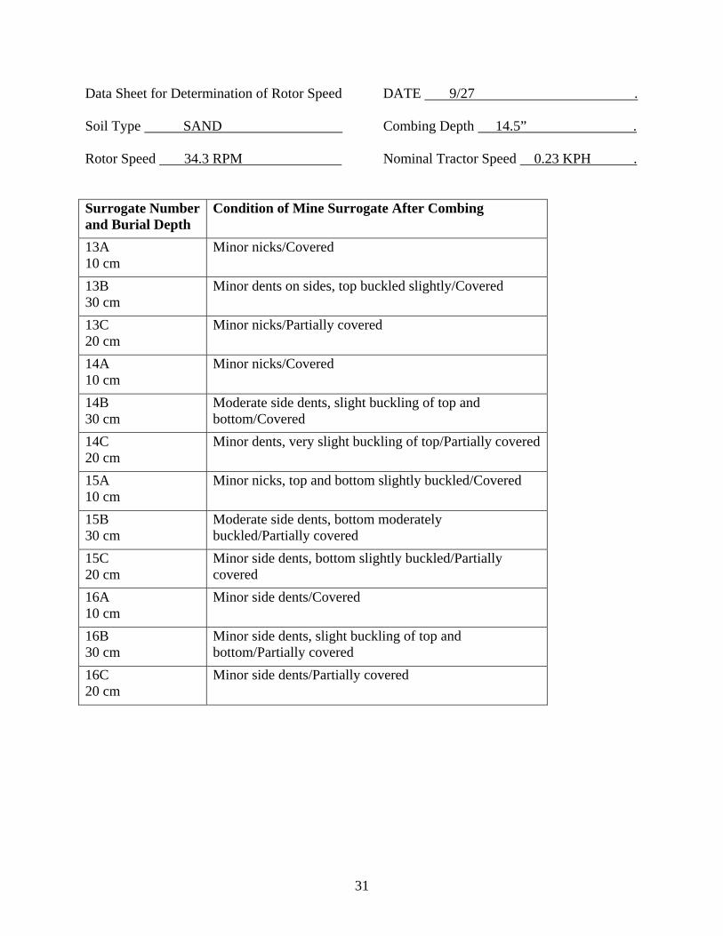
Data Sheet for Determination of Rotor Speed DATE 9/27 . Soil Type SAND Combing Depth 14.5” . Rotor Speed 34.3 RPM Nominal Tractor Speed 0.23 KPH . Surrogate Number and Burial Depth
Condition of Mine Surrogate After Combing
13A 10 cm
Minor nicks/Covered
13B 30 cm
Minor dents on sides, top buckled slightly/Covered
13C 20 cm
Minor nicks/Partially covered
14A 10 cm
Minor nicks/Covered
14B 30 cm
Moderate side dents, slight buckling of top and bottom/Covered
14C 20 cm
Minor dents, very slight buckling of top/Partially covered
15A 10 cm
Minor nicks, top and bottom slightly buckled/Covered
15B 30 cm
Moderate side dents, bottom moderately buckled/Partially covered
15C 20 cm
Minor side dents, bottom slightly buckled/Partially covered
16A 10 cm
Minor side dents/Covered
16B 30 cm
Minor side dents, slight buckling of top and bottom/Partially covered
16C 20 cm
Minor side dents/Partially covered

32
Data Sheet for Determination of Rotor Speed DATE 9/27 . Soil Type Compacted Clay Combing Depth 14.0” . Rotor Speed____12 RPM________________ Nominal Tractor Speed 0.10 KPH . Surrogate Number and Burial Depth
Condition of Mine Surrogate After Combing
1A 10 cm
Moderate dent on sides, bottom buckled
1B 30 cm
Large dents on sides, top and bottom buckled significantly
1C 20 cm
Tiny nicks/Covered
2A 10 cm
Moderate dent on side, bottom buckled
2B 30 cm
Major holes and dents in top and bottom
2C 20 cm
Minor side dents/Covered
3A 10 cm
Moderate dent on side, bottom buckled
3B 30 cm
Case ruptured and folded/Completely covered
3C 20 cm
Minor nicks
4A 10 cm
Slight dents and slight buckling of bottom
4B 30 cm
Major side dent, top and bottom buckled/Covered
4C 20 cm
Moderate dents in side, minor buckling of top

33
Data Sheet for Determination of Rotor Speed DATE 9/27 . Soil Type Compacted Clay Combing Depth 14.” . Rotor Speed 18.5 RPM Nominal Tractor Speed 0.10 KPH . Surrogate Number and Burial Depth
Condition of Mine Surrogate After Combing
5A 10 cm
Minor nicks
5B 30 cm
Major side dent and top buckle
5C 20 cm
Moderate side dent and bottom buckle/90% covered
6A 10 cm
Minor dents, slight buckle on bottom
6B 30 cm
Was speared on tines and carried under track. Burst open
6C 20 cm
Moderate side dents/Covered
7A 10 cm
Tiny nicks
7B 30 cm
Major side dents and bottom buckle
7C 20 cm
Minor side dents, bottom slightly buckled
8A 10 cm
Minor dents, bottom slightly buckled
8B 30 cm
Was speared on tines. Brought comb up
8C 20 cm
Major side dents and rupture of bottom

34
Data Sheet for Determination of Rotor Speed DATE 9/27 . Soil Type Compacted Clay Combing Depth 14.” . Rotor Speed 25.7 RPM Nominal Tractor Speed 0.10 KPH . Surrogate Number and Burial Depth
Condition of Mine Surrogate After Combing
9A 10 cm
Tiny nicks
9B 30 cm
Heavy dents, case rupture
9C 20 cm
Heavy side dents and top and bottom buckle
10A 10 cm
Tiny nicks
10B 30 cm
Speared on tines
10C 20 cm
Moderate side dent and top and bottom buckle
11A 10 cm
Minor nicks
11B 30 cm
Ripped open
11C 20 cm
Heavy dent and moderate buckling/Partially covered
12A 10 cm
Moderate dent and slight buckling of bottom/Partially covered
12B 30 cm
Speared on tines
12C 20 cm
Heavy side dent

35
Data Sheet for Determination of Rotor Speed DATE 9/27 . Soil Type Compacted Clay Combing Depth 14.” . Rotor Speed 34.7 RPM Nominal Tractor Speed 0.10 KPH . Surrogate Number and Burial Depth
Condition of Mine Surrogate After Combing
13A 10 cm
Tiny nicks
13B 30 cm
Speared on tine
13C 20 cm
Not recovered
14A 10 cm
Moderate side dents, slight buckling of top and bottom/Covered
14B 30 cm
Speared on tine
14C 20 cm
Heavy side dent, bottom slightly buckled
15A 10 cm
Minor side dents
15B 30 cm
Heavy damage, case shredded
15C 20 cm
Moderate side dent/90% covered
16A 10 cm
Moderate side dent, slight buckling of top and bottom
16B 30 cm
Speared on tine
16C 20 cm
Heavy side dent, moderate buckling of bottom

36
APPENDIX 2 Determination of Effective Combing Width DATA SHEET MINE NUMBER
OFFSET FROM CENTER
OBSERVATION
7B 155 CM Visibly bumped/ did not break the surface 11A 155 CM Visibly bumped/ did not break the surface 14C 155 CM Visibly bumped/ did not break the surface 14A 155 CM Visibly bumped/ did not break the surface 8A 155 CM Visibly bumped/ did not break the surface 4B 145 CM Visibly bumped/ did not break the surface 2A 145 CM Visibly bumped/ did not break the surface 3A 145 CM Visibly bumped/ did not break the surface 10A 145 CM Visibly bumped/ did not break the surface 12A 145 CM Visibly bumped/ did not break the surface 15A 135 CM Visibly bumped/ did not break the surface 8B 135 CM Visibly bumped/ did not break the surface 1A 135 CM Visibly bumped/ did not break the surface 13A 135 CM Visibly bumped/ did not break the surface 2C 135 CM Visibly bumped/ did not break the surface 11C 125 CM Visibly bumped/ Appeared at side/was pushed
back into tractor path and dropped 6C 125 CM Visibly bumped/ did not break the surface 13C 125 CM Visibly bumped/ did not break the surface 4A 125 CM Visibly bumped/ did not break the surface 15C 125 CM Visibly bumped/ did not break the surface/Ended
up slightly below grade 9C 115 CM Visibly bumped / Became slightly visible 10B 115 CM Visibly bumped / Became slightly visible 8A 115 CM Visibly bumped / Became fully visible 5C 115 CM Visibly bumped / Became fully visible / Was
pushed back into tractor path just outside tire 7A 115 CM Visibly bumped / Became slightly visible 1B 105 CM Visibly bumped / Became fully visible 5A 105 CM Visibly bumped / Became fully visible 7C 105 CM Visibly bumped / Became fully visible 4C 105 CM Visibly bumped / Became fully visible 6A 105 CM Visibly bumped / did not break surface 16A 95 CM Visibly bumped / Became fully visible

37
12C 95 CM Visibly bumped / Became slightly visible 9A 95 CM Visibly bumped / Became fully visible 12A 95 CM Visibly bumped / Became fully visible 9B 95 CM Visibly bumped / Became fully visible 13A 85 CM Visibly bumped / Became fully visible 9A 85 CM Visibly bumped / Became fully visible 4A 85 CM Visibly bumped / Became fully visible 3B 85 CM Visibly bumped / Became fully visible 2A 85 CM Visibly bumped / Became fully visible

38
APPENDIX 3 RANDOM MINEFIELD LAYOUT DATA SHEETS FOR COMBING RUNS DATA SHEETS FOR MINES RECOVERED

39
#10,23,20
#23,8,40
#33,32,20
#45,4,20
#55,33,10
#65,32,40
#76,15,40
#86,35,10
#96,39,10
#107,33,10
#118,31,10
#128,34,30
#1310,11,20
#1411,34,30
#1513,16,40
#1613,29,10
#1714,39,40
#1815,29,30
#1916,34,10
#2018,38,20
#2119,0,30
#2219,23,20
#2323,19,40
#2423,37,30
#2525,8,20
#2625,22,30
#2725,35,10
#2826,8,30
#2926,28,20
#3027,6,40
#3127,25,40
#3228,15,40
#3329,34,10
#3430,13,30
#3531,21,10
#3633,32,40
#3735,11,30
#3835,20,10
#3935,31,40
#4036,10,40
#4136,39,10
#4237,17,30
#4337,21,10
#4438,21,30
#4538,34,10
#4639,4,30
#4739,18,20
#4839,26,30
#4939,34,20
#5039,38,30
#510,20,10
#521,11,10
#31,16,10
#541,31,20
#551,38,10
#563,38,20
#574,8,30
#584,33,20
#594,38,30
#607,3,10
#618,5,30
#629,18,10
#639,19,10
#6410,4,30
#6510,21,20
#6611,6,20
#6711,31,20
#6812,20,10
#6913,31,20
#7014,11,30
#7115,8,30
#7215,23,30
#7317,35,10
#7419,34,20
#7520,19,20
#7621,11,30
#7721,28,10
#7822,20,30
#7922,22,20
#8023,35,10
#8124,33,10
#8225,9,30
#8326,17,30
#8426,23,20
#8529,2,10
#8630,4,10
#8730,35,20
#8831,30,10
#8932,5,20
#9032,8,20
#9132,16,20
#9234,17,30
#9334,21,20
#9435,5,20
#9536,7,30
#9636,8,20
#9736,40,20
#9837,31,30
#9937,33,10
#10038,9,20
#1010,12,10
#1021,22,30
#1033,33,30
#1046,13,20
#1057,6,30
#1067,27,20
#1077,37,10
#1088,17,20
#1098,38,10
#11010,22,30
#11114,15,20
#11214,23,20
#11315,35,30
#11417,7,30
#11517,29,30
#11618,39,10
#11720,9,30
#11820,16,20
#11922,0,30
#12022,2,10
#12123,0,30
#12223,1,20
#12323,10,10
#12423,16,10
@12523,20,20
#12624,15,10
#12725,7,30
#12825,20,10
#12927,14,30
#13028,19,10
#13129,13,10
#13229,23,10
#13329,35,30
#13429,39,30
#13530,9,30
#13630,10,10
#13730,22,10
#13830,32,20
#13931,9,30
#14032,39,10
#14134,24,20
#14235,21,30
#14336,19,20
#14436,20,20
#14536,37,10
#14637,7,20
#14737,29,10
#14838,25,10
#14938,36,20
#15039,36,30
Figure 16. MINE COORDINATES AND BURIAL DEPTH

41
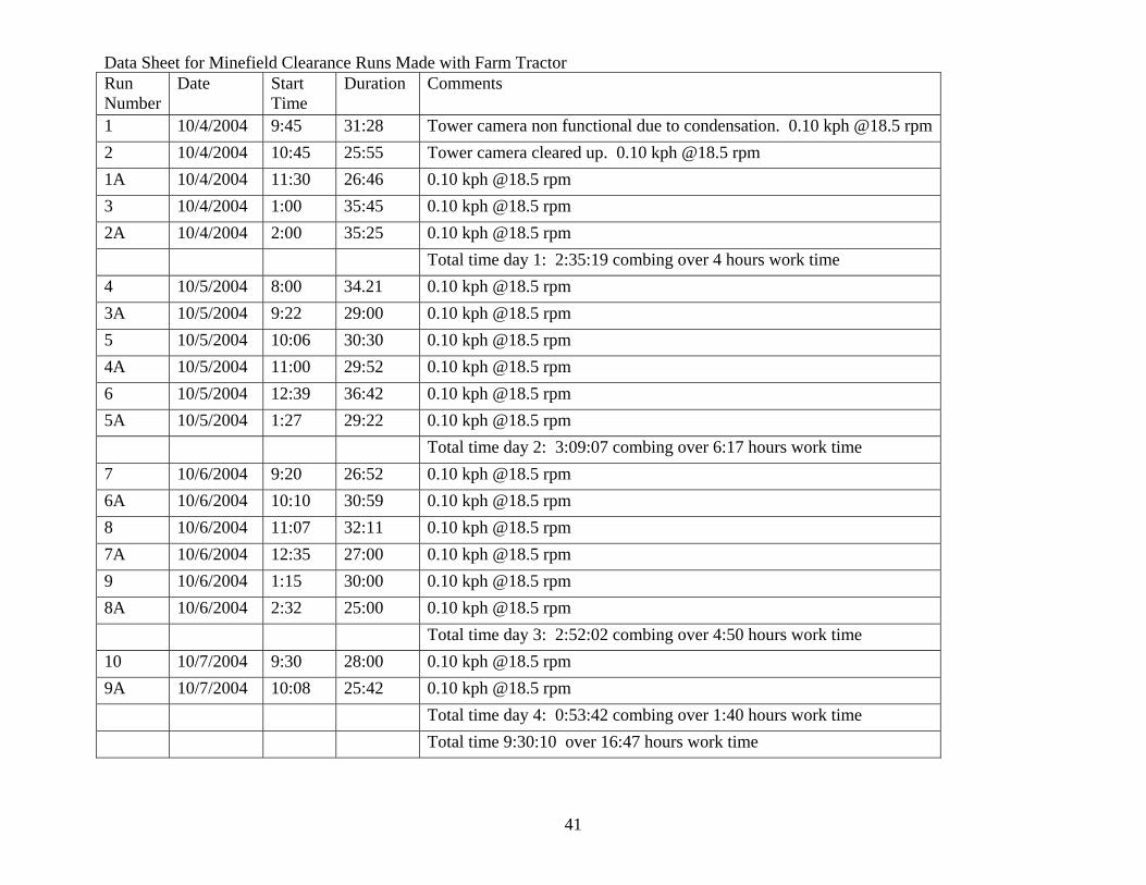
Data Sheet for Minefield Clearance Runs Made with Farm Tractor Run Number
Date Start Time
Duration Comments
1 10/4/2004 9:45 31:28 Tower camera non functional due to condensation. 0.10 kph @18.5 rpm2 10/4/2004 10:45 25:55 Tower camera cleared up. 0.10 kph @18.5 rpm 1A 10/4/2004 11:30 26:46 0.10 kph @18.5 rpm 3 10/4/2004 1:00 35:45 0.10 kph @18.5 rpm 2A 10/4/2004 2:00 35:25 0.10 kph @18.5 rpm Total time day 1: 2:35:19 combing over 4 hours work time 4 10/5/2004 8:00 34.21 0.10 kph @18.5 rpm 3A 10/5/2004 9:22 29:00 0.10 kph @18.5 rpm 5 10/5/2004 10:06 30:30 0.10 kph @18.5 rpm 4A 10/5/2004 11:00 29:52 0.10 kph @18.5 rpm 6 10/5/2004 12:39 36:42 0.10 kph @18.5 rpm 5A 10/5/2004 1:27 29:22 0.10 kph @18.5 rpm Total time day 2: 3:09:07 combing over 6:17 hours work time 7 10/6/2004 9:20 26:52 0.10 kph @18.5 rpm 6A 10/6/2004 10:10 30:59 0.10 kph @18.5 rpm 8 10/6/2004 11:07 32:11 0.10 kph @18.5 rpm 7A 10/6/2004 12:35 27:00 0.10 kph @18.5 rpm 9 10/6/2004 1:15 30:00 0.10 kph @18.5 rpm 8A 10/6/2004 2:32 25:00 0.10 kph @18.5 rpm Total time day 3: 2:52:02 combing over 4:50 hours work time 10 10/7/2004 9:30 28:00 0.10 kph @18.5 rpm 9A 10/7/2004 10:08 25:42 0.10 kph @18.5 rpm Total time day 4: 0:53:42 combing over 1:40 hours work time Total time 9:30:10 over 16:47 hours work time

42
Data Sheet for Minefield Clearance Runs Made with Construction Dozer Run Number
Date Start Time
Duration Comments
1 11/16/2004 8:17 24:27 2 11/16/2004 10:00 36:01 Total time day 1: 1:00:28 over 2:30 hours work time 1A 11/17/2004 9:20 23:15 Combed toward sun 3 11/17/2004 9:48 1:02:52 Combed away from sun 2A 11/17/2004 12:10 41:14 Combed toward sun 4 11/17/2004 1:20 26:17 Combed toward sun 3A 11/17/2004 1:54 16:30 Combed toward sun Total time day 2: 2:48:08 over 4:10 hours work time 5 11/18/2004 7:40 28:00 Overcast 4A 11/18/2004 8:13 25:41 Overcast 6 11/18/2004 9:00 21:05 Overcast 5A 11/18/2004 9:30 15:30 7 11/18/2004 10:03 34:12 6A 11/18/2004 10:45 31:20 8 11/18/2004 12:48 26:00 7A 11/18/2004 1:25 28:15 9 11/18/2004 2:06 26:24 Total time day 3: 3:56:27 over 6:30 hours work time 8A 11/19/2004 7:55 18:37 Camera was very clear. Over cast morning. 10 11/19/2004 8:28 21:43 Total time day 4: 0:40:20 combing over 0:54 hours work time Total time 8:25:23 over 14:00 hours work time

43
Data Sheet for Minefield Clearance – Mines Encountered with Farm Tractor Mine Number/ Mine Type
Appeared to Ground Observer Date/Run Time
Appeared to Camera Observer
Initial Status Fired/Not
Cleared/ Not Cleared
Final Status Fired/ Not Fired
Comments
119 Type 72 10/4 – Run1 15:20 Yes Not Broke apart. 122 Type 72 10/4 – Run1 19:10 Yes Fired Rubber ripped off 119 Type 72 10/4 – Run1 19:10 Yes Not 21 AT 10/4 – Run1 No Cleared Not Speared by tine and torn apart. Bottom
popped off 85 PMN 10/4 – Run1 24:07 Yes Fired Rubber top missing 4 AT 10/4 – Run2 3:47 Yes Cleared Not Good shape 46 AT 10/4 – Run2 21:50 Yes Not Cleared Fired Bottom popped off 60 PMN 10/4 – Run1A 4:10 No Fired Good shape 64 PMN 10/4 – Run1A No Fired Rubber missing 91 PMN 10/4 – Run1A No Fired Rubber missing 71 PMN 10/4 – Run3 16:10 Yes Fired Rubber missing 117 Type 72 10/4 – Run3 20:08 Yes Fired Good shape 28 AT 10/4 – Run3 23:30 Yes Fired Dented 136 Type 72 10/4 – Run3 26:10 Yes Not Good shape 135 Type 72 10/4 – Run3 28:00 No Not ? PMN 10/4 – Run3 28:00 Yes Fired 146 Type 72 10/4 – Run3 31:59 Yes Fired 10 AT 10/4 – Run3 31:59 Yes Not Fired Run over, saw on backup of tractor False Call 2 AT 10/4 – Run2A 6:02 Yes Cleared Not 61 PMN 10/4–Run2A 12:00 Yes Fired Top knocked off 66 PMN 10/4-Run2A 18:00 Yes Fired Top knocked off 25 AT 10/4-Run2A 27:00 Yes Not Cleared Not Bottom gone 127 Type 72 10/4-Run2A 31:00 Yes Fired Top knocked off 30 AT 10/4-Run2A 35:00 Yes Not Cleared Not Good Shape 86 PMN 10/4-Run2A 37:30 Yes Fired Good Shape 104 Type 72 10/5 – Run4 6:02 Yes Not 131 Type 72 10/5 – Run4 22:20 No Not 34 AT 10/5 – Run4 22:20 Yes Not Cleared Not

44
Mine Number/ Mine Type
Appeared to Ground Observer Date/Run Time
Appeared to Camera Observer
Initial Status Fired/Not
Cleared/ Not Cleared
Final Status Fired/ Not Fired
Comments
129 Type 72 10/5 – Run4 23:25 Yes Fired ? AT 10/5 – Run4 28:15 Yes Fired Cleared Fired May be AT #37 101 Type 72 10/5 – Run3A 0:55 Yes Not 13 AT 10/5 –Run3A 7:55 Yes Not Cleared Not 82 PMN 10/5-Run3A 18:20 Yes Not 100 PMN 10/5-Run3A No Fired 123 Type 72 10/5-Run3A No Not 63 PMN 10/5-Run5 7:44 Yes Not 91 PMN 10/5-Run5 21:29 Yes Not 95 PMN 10/5-Run5 25:01 Yes Not 42 AT 10/5-Run5 27:29 Yes Not Not Cleared Yes Carried to back of comb, dropped and run
over and fired 118 Type 72 10/5-Run5 No Not 7 AT 10/5-Run4A 7:00 Yes Not Cleared Not 108 Type 72 10/5-Run4A 7:30 Yes Fired 15 AT 10/5-Run4A 11:35 Yes Not Cleared Not 124 Type 72 10/5-Run4A 17:30 Yes Not 32 AT 10/5-Run4A 22:40 Yes Not 126 Type 72 10/5-Run4A No Not 70 PMN 10/5-Run4A No Fired 76 PMN 10/5-Run4A No Fired 83 PMN 10/5-Run4A No Fired ? Type 72 10/5-Run6 No
Not
137 Type 72 10/5-Run6 Yes Not 35 AT 10/5-Run6 Yes Not Cleared Not 142 Type 72 10/5-Run6 Yes Fired 43 AT 10/5-Run6 Yes Not Cleared Not 44 AT 10/5-Run6 Yes Not Cleared Not 47 AT 10/5-Run6 No Not Clered Not 51 PMN 10/5-Run5A 2:30 Yes Fired

45
Mine Number/ Mine Type
Appeared to Ground Observer Date/Run Time
Appeared to Camera Observer
Initial Status Fired/Not
Cleared/ Not Cleared
Final Status Fired/ Not Fired
Comments
65 PMN 10/5-Run5A Yes Not 23 AT 10/5-Run5A No Not Cleared Not 38 AT 10/5-Run5A No Not Cleared Not 62 PMN 10/5-Run5A 7:36 Yes Fired 125 Type 72 10/5-Run5A 14:00 Yes Not 75 PMN 10/5-Run5A 14:30 No Fired 128 Type 72 10/5-Run5A 14:57 Yes Not 78 PMN 10/5-Run5A 17:18 Yes Fired 130 Type 72 10/5-Run5A 19:36 Yes Not 143 Type 72 10/5-Run5A 26:05 Yes Not 68 PMN 10/5-Run5A No Fired 31 AT 10/6-Run7 16:31 Yes Not Cleared Not 48 AT 10/6-Run7 No Fired Not Cleared Fired Saw smoke in camera 10/6-Run7 24:54 False AP Call 1 AT 10/6-Run6A 2:10 Yes Not Cleared Not 79 PMN 10/6-Run6A 14:19 Yes Fired 22 AT 10/6-Run6A No Not Cleared Not 26 AT 10/6-Run6A 17:13 Yes Not Cleared Not 84 PMN 10/6-Run6A 17:22 Yes Fired 31 AT 10/6-Run6A 20:54 Yes Not Cleared Not 141 Type 72 10/6-Run6A 26:11 No Not Was seen in tower camera 148 Type 72 10/6-Run6A 29:04 Yes Not 11 AT 10/6-Run8 7:43 Yes Not Cleared Not 67 PMN 10/6-Run8 10:18 Yes Not 18 AT 10/6-Run8 13:41 Yes Not Cleared Not Comb shook bad, tines lifted. Either this
or #12 fired 39 AT 10/6-Run8 27:42 No Not Cleared Not Was seen in tower camera 3 AT 10/6-Run8 No Not Cleared Not 5 AT 10/6-Run8 No Not Cleared Not 11 AT 10/6-Run8 No Not Cleared Not 34 AT 10/6-Run8 No Not Cleared Not

46
Mine Number/ Mine Type
Appeared to Ground Observer Date/Run Time
Appeared to Camera Observer
Initial Status Fired/Not
Cleared/ Not Cleared
Final Status Fired/ Not Fired
Comments
16 AT 10/6-Run7A 9:28 Yes Not Cleared Not 29 AT 10/6-Run7A No Not Cleared Not 8 AT 10/6-Run9 3:00 Yes Not Cleared Not 73 PMN 10/6-Run9 10:25 Yes Fired 113 Type 72 10/6-Run9 11:30 Yes Fired 24 AT 10/6-Run9 15:50 Yes Fired Cleared Fired Fired, then cleared 80 PMN 10/6-Run9 15:50 Yes Fired 88 PMN 10/6-Run9 No Fired 27 AT 10/6-Run9 14:30 Yes Not Cleared Not 33 AT 10/6-Run9 18:30 Yes Not Cleared Not 45 AT 10/6-Run9 24:00 Yes Not Cleared Not 19 AT 10/6-Run9 No Not Cleared Not 49 AT 10/6-Run9 No Not Cleared Not 54 PMN 10/6-Run8A 2:12 Yes Fired 10/6-Run8A False Call 3 AT 10/6-Run8A 2:35 Yes Not Cleared Not 5 AT 10/6-Run8A 4:00 Yes Not Cleared Not ? Type 72 10/6-Run8A 5:00 Yes Fired No number visible on mine 6 AT 10/6-Run8A 5:10 Yes Not Cleared Not 10 AT 10/6-Run8A 6:30 Yes Not Cleared Not 58 PMN 10/6-Run8A No Fired 11 AT 10/6-Run8A 7:33 Yes Not Cleared Not 14 AT 10/6-Run8A 8:47 Yes Not Cleared Not 19 AT 10/6-Run8A 10:30 Yes Not Cleared Not 81 PMN 10/6-Run8A 16:30 Yes Not 36 AT 10/6-Run8A 18:30 Yes Not Cleared Not 39 AT 10/6-Run8A 19:30 Yes Not Cleared Not XX1 Type 72 10/6-Run8A 19:30 Yes Unrecognizable Type 72 Mine 49 AT 10/6-Run8A 22:00 Yes Not Cleared Not 12 AT 10/6 Cleared Was missed by camera and ground
observer but found cleared

47
Mine Number/ Mine Type
Appeared to Ground Observer Date/Run Time
Appeared to Camera Observer
Initial Status Fired/Not
Cleared/ Not Cleared
Final Status Fired/ Not Fired
Comments
9 AT 10/7-Run10 5:17 Yes Not Cleared Not 17 AT 10/7-Run10 9:00 Yes Not Cleared Not 140 Type 72 10/7-Run10 20:00 Yes Not 41 AT 10/7-Run10 22:00 Yes Not Cleared Not 50 AT 10/7-Run10 25:00 Yes Not Not Cleared Not 55 PMN 10/7-Run9A 5:00 No Fired 109 Type 72 10/7-Run9A 5:30 Yes Not 20 AT 10/7-Run9A 10:56 Yes Not Cleared Not 87 PMN 10/7-Run9A 18:13 Yes Fired 133 Type 72 10/7-Run9A No Fired

48
Data Sheet for Minefield Clearance – Mines Encountered with Construction Dozer Mine Number
Appeared to Ground Observer Date/Time
Appeared to Camera Observer
Initial Status Fired/Not
Cleared/ Not Cleared
Final Status Fired/ Not Fired
Comments
122 Type 72 11/16-Run1 13:16 Yes Not Not Cleared Not 121 Type 72 11/16-Run1 No Not Not Cleared Not 21 AT 11/16-Run1 14:11 Yes Fired Not Cleared Fired 89 Type 72 11/16-Run2 7:52 Yes Fired Not Cleared Fired 24 AT 11/16-Run2 31:03 Yes Fired Not Cleared Fired 60 PMN 11/17-Run1A 3:40 No Not Cleared Not 105 Type 72 11/17-Run1A 5:29 No Not Cleared Not 61 PMN 11/17-Run1A 5:42 No Fired Cleared Fired 64 PMN 11/17-Run1A 6:12 No Fired Cleared Fired 120 Type 72 11/17-Run1A 10:30 No Fired Cleared Fired 119 Type 72 11/17-Run1A 11:12 No Not Cleared Not 85 PMN 11/17-Run1A 15:07 No Not Cleared Not 46 AT 11/17-Run1A 20:09 No Not Cleared Not 11/17-Run3 1:00 False Call 100 PMN 11/17-Run3 2:28 Yes Not Cleared Not 37 AT 11/17-Run3 6:00 Yes Not Cleared Not 40 AT 11/17-Run3 11:00 No No No Went under track 96 PMN 11/17-Run3 11:00 No Fired Cleared Fired 135 Type 72 11/17-Run3 15:00 Yes Fired Not Cleared Fired 136 Type 72 11/17-Run3 16:27 No Not Not Cleared Not 139 Type 72 11/17-Run3 16:50 Yes Fired Not Cleared Fired 90 PMN 11/17-Run3 17:50 No Fired Not Cleared Fired 11/17-Run3 24:00 False Call 11/17-Run3 27:00 False Call 82 PMN 11/17-Run3 29:00 Yes Fired Cleared Fired 25 AT 11/17-Run3 34:00 Yes ** ** ** Operator error. Set comb on mine after
repositioning tractor 117 Type 72 11/17-Run3 39:00 Yes Fired Not Cleared Fired 11/17-Run3 46:00 False Call 70 PMN 11/17-Run3 49:00 Yes Fired Not Cleared Fired

49
Mine Number
Appeared to Ground Observer Date/Time
Appeared to Camera Observer
Initial Status Fired/Not
Cleared/ Not Cleared
Final Status Fired/ Not Fired
Comments
2 AT 11/17-Run2A 5:36 Yes Not Cleared Not 57 PMN 11/17-Run2A 13:23 Yes Fired Cleared Fired ? Type 72 11/17-Run2A 21:42 Yes Unrecognizable mine case 25 AT 11/17-Run2A 28:31 Yes Not Cleared Not 30 AT 11/17-Run2A 29:21 Yes Not Cleared Not 11/17-Run2A 33:47 False Call 94 PMN 11/17-Run2A No Fired Cleared Fired 32 AT 11/17-Run4 16:33 Yes Not Cleared Not 126 Type 72 11/17-Run4 24:00 No Fired Cleared Fired 52 PMN 11/17-Run3A 2:00 No Fired Cleared Fired 13 AT 11/17-Run3A 13:16 Yes Mine Bottom 131 Type 72 11/17-Run3A 13:16 Yes Fired Not Cleared Fired ? AT 11/17-Run3A 14:11 Yes Not ** Not Number unrecognizable, probably 34.
This mine was removed before give a chance to clear
40 AT 11/17-Run3A 15:00 Yes Not Cleared Not 23 AT 11/18-Run5 14:30 Yes Not Not Cleared Not Made it to middle of rotor 75 PMN 11/18-Run5 15:30 Yes Fired Not Cleared Fired 108 Type 72 11/18-Run5 22:20 Yes Fired Not Cleared Fired 47 AT 11/18-Run4A 2:40 Yes Not Cleared Not 42 AT 11/18-Run4A 4:58 Yes Not Not cleared Fired Circulated in interior and then fired and
ended up under tracks 91 PMN 11/18-Run4A 8:50 Yes Not Not Cleared Not 83 PMN 11/18-Run4A 11:38 Yes Fired Not cleared Fired 172 Type 72 11/18-Run4A 13:45 Yes Not Not Cleared Not This is not a valid serial number 118 Type 72 11/18-Run4A 15:38 Yes Not Not Cleared Not 111 Type 72 11/18-Run4A 19:00 Yes Not Not Cleared Not 15 AT 11/18-Run4A 19:28 Yes Not Cleared Not 7 AT 11/18-Run4A No Not Cleared Not 1 AT 11/18-Run6 1:03 Yes Not Cleared Not 72 PMN 11/18-Run6 8:30 Yes Fired Cleared Fired

50
Mine Number
Appeared to Ground Observer Date/Time
Appeared to Camera Observer
Initial Status Fired/Not
Cleared/ Not Cleared
Final Status Fired/ Not Fired
Comments
22 AT 11/18-Run6 No Not Cleared Not 26 AT 11/18-Run6 12:07 Yes Not Cleared Not 84 PMN 11/18-Run6 13:53 No Fired Cleared Fired 143 Type 72 11/18-Run5A 2:15 Yes Not Cleared Not 44 AT 11/18-Run5A 2:50 Yes Not Cleared Not 43 AT 11/18-Run5A 3:03 Yes Not Cleared Not 38 AT 11/18-Run5A 3:30 Yes Not Cleared Not 92 PMN 11/18-Run5A 3:30 Yes Not Cleared Not 35 AT 11/18-Run5A 5:00 Yes Not Cleared Not 84 PMN 11/18-Run5A 6:15 Yes Fired Cleared Fired 22 AT 11/18-Run5A 8:00 Yes Not Cleared Not 62 PMN 11/18-Run5A 10:30 Yes Not Cleared Not 63 PMN 11/18-Run5A 10:50 Yes Not Cleared Not 11/18-Run7 5:20 False Call 11/18-Run7 14:23 False Call 77 PMN 11/18-Run7 19:50 Yes Fired Not Cleared Fired 29 AT 11/18-Run7 25:00 No Not Cleared Not 147 Type 72 11/18-Run7 30:17 Yes Not Not Cleared Not 11/18-Run6A False Call 29 AT 11/18-Run6A 19:28 Yes Not Cleared Not 31 AT 11/18-Run6A 20:27 Yes Not Cleared Not 48 AT 11/18-Run6A 28:00 No Not Cleared Not 5 AT 11/18-Run8 2:00 Yes Not Not Cleared Not 58 PMN 11/18-Run8 3:50 Yes Fired Not Cleared Fired 14 AT 11/18-Run8 9:00 Yes Not Cleared Not 59 PMN 11/18-Run8 12:00 Yes Fired Not Cleared Fired 81 PMN 11/18-Run8 16:30 Yes Fired Not Cleared Fired 33 AT 11/18-Run8 20:06 No Not Cleared Not 45 AT 11/18-Run8 23:00 No Not Cleared Not 49 AT 11/18-Run8 25:00 Yes Not Cleared Not 93 PMN 11/18-Run8 No Fired Cleared Fired

51
Mine Number
Appeared to Ground Observer Date/Time
Appeared to Camera Observer
Initial Status Fired/Not
Cleared/ Not Cleared
Final Status Fired/ Not Fired
Comments
51 PMN 11/18-Run8 No Fired Cleared Fired 53 PMN 11/18-Run8 No Not Cleared Not 3 AT 11/18-Run7A 2:55 Yes Fired Cleared Fired 5 AT 11/18-Run7A 3:40 Yes Not Cleared Not 54 PMN 11/18-Run7A 7:32 Yes Fired Not Cleared Fired 16 AT 11/18-Run7A 10:24 Yes Not Cleared Not 18 AT 11/18-Run7A 12:32 Yes Not Cleared Not 11 AT 11/18-Run7A 15:54 Yes Not Cleared Not 36 AT 11/18-Run7A 22:49 Yes Not Cleared Not 39 AT 11/18-Run7A No Not Cleared Not 98 PMN 11/18-Run7A No Fired Cleared Fired ? AT 11/18-Run9 15:30 Yes Seen on camera, but ground observer
failed to answer radio call ? AP 11/18-Run9 16:30 Yes Seen on camera, but ground observer
failed to answer radio call 145 Type 72 11/18-Run9 22:30 Yes Not Cleared Not 50 AT 11/18-Run9 24:51 Yes Not Cleared Not 134 Type 72 11/18-Run9 No Found in lane after run 45 AT 11/19-Run8A 0:29 Yes Not Cleared Not 149 Type 72 11/19-Run8A 1:29 Yes Not Not Cleared Not 33 AT 11/19-Run8A 3:49 Yes Not Not Cleared Fired Caught between depth gauge and tine 87 PMN 11/19-Run8A 3:49 Yes Not Not Cleared Not 24 AT 11/19-Run8A 7:08 Yes Not Cleared Not 27 AT 11/19-Run8A 7:08 Yes Not Cleared Not 80 PMN 11/19-Run8A 7:42 Yes Not Not Cleared Not 73 PMN 11/19-Run8A 10:02 Yes Fired Not Cleared Fired 74 PMN 11/19-Run8A 11:27 Yes Not Cleared Not 10 AT 11/19-Run8A 14:08 Yes Not Cleared Not 8 AT 11/19-Run8A 14:58 Yes Not Cleared Not 6 AT 11/19-Run8A 14:58 Yes Not Cleared Not 59 PMN 11/19-Run8A 17:03 Yes Fired Cleared Fired

52
Mine Number
Appeared to Ground Observer Date/Time
Appeared to Camera Observer
Initial Status Fired/Not
Cleared/ Not Cleared
Final Status Fired/ Not Fired
Comments
56 PMN 11/19-Run10 2:45 Yes Fired Cleared Fired 107 Type 72 11/19-Run10 2:45 Yes Fired Cleared Fired 109 Type 72 11/19-Run10 4:10 Yes Not Not Cleared Not 9 AT 11/19-Run10 5:00 Yes Not Cleared Not 17 AT 11/19-Run10 8:50 Yes Not Cleared Not 20 AT 11/19-Run10 10:18 Yes Not Cleared Not 116 Type 72 11/19-Run10 10:18 Yes Fired Cleared Fired 41 AT 11/19-Run10 18:32 Yes Not Cleared Not