Embed Size (px)
Citation preview
8/3/2019 Testing Low Impedance
http://slidepdf.com/reader/full/testing-low-impedance 1/48
Testing Low ImpedanceBus Differential Relays
International ProTesT User Group Meeting
Vancouver, BC
8/3/2019 Testing Low Impedance
http://slidepdf.com/reader/full/testing-low-impedance 2/48
What You’ll Learn
• Basics of bus differential protection• Differential Protection Methods
• Guidelines for testing low impedance
bus differential relays
8/3/2019 Testing Low Impedance
http://slidepdf.com/reader/full/testing-low-impedance 3/48
Basics of Differential Protection
• Based on Kirchoff’s Current Law (KCL) – The sum of currents entering and exiting a
node must equal 0
– Think of a bus as a node
8/3/2019 Testing Low Impedance
http://slidepdf.com/reader/full/testing-low-impedance 4/48
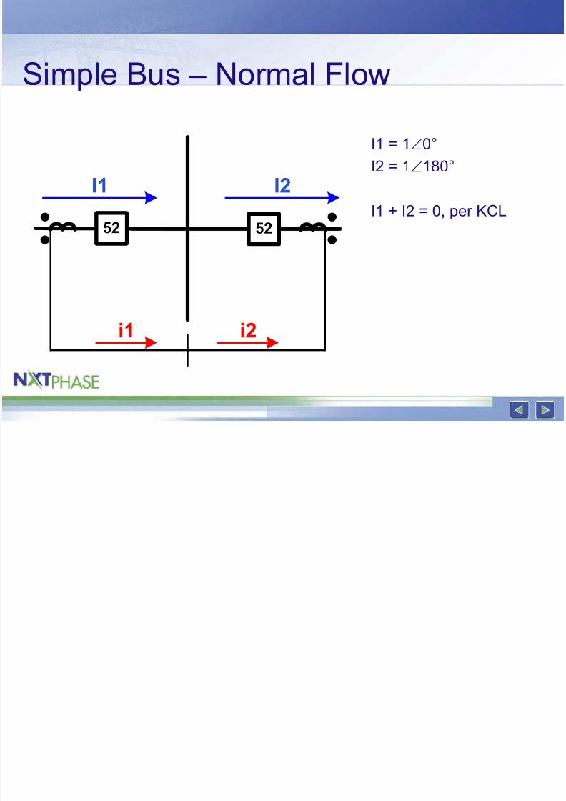
Simple Bus – Normal Flow
52 52
I1 I2
i1 i2
I1 = 1∠0°I2 = 1∠180°
I1 + I2 = 0, per KCL
8/3/2019 Testing Low Impedance
http://slidepdf.com/reader/full/testing-low-impedance 5/48
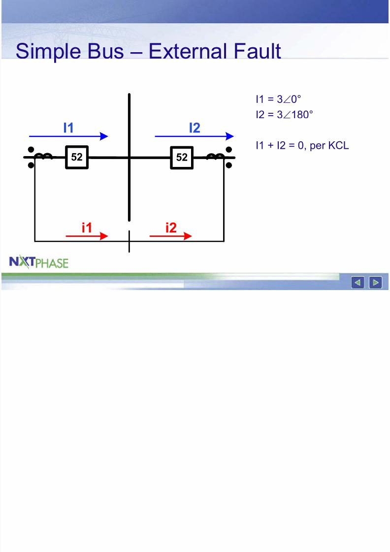
Simple Bus – External Fault
52 52
I1 I2
i1 i2
I1 = 3∠0°I2 = 3∠180°
I1 + I2 = 0, per KCL
8/3/2019 Testing Low Impedance
http://slidepdf.com/reader/full/testing-low-impedance 6/48
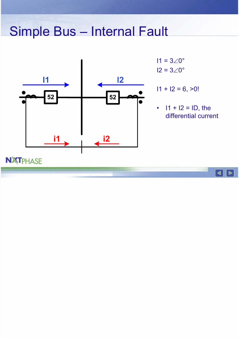
Simple Bus – Internal Fault
I1 = 3∠0°I2 = 3∠0°
I1 + I2 = 6, >0!
• I1 + I2 = ID, the
differential current
52 52
I1 I2
i1 i2
8/3/2019 Testing Low Impedance
http://slidepdf.com/reader/full/testing-low-impedance 7/48
Differential Protection
• Looks for the presence of differentialcurrent
• Reliable protection concept
• Several different techniques
8/3/2019 Testing Low Impedance
http://slidepdf.com/reader/full/testing-low-impedance 8/48
Bus Fault Protection Requirements
• High speed – Bus faults are typically high-magnitude,
damaging events
• Secure – Incorrect tripping a bus can drop a significant
part of the system
8/3/2019 Testing Low Impedance
http://slidepdf.com/reader/full/testing-low-impedance 9/48
Bus Protection Techniques
• Overcurrent• High Impedance Differential
• Low Impedance Differential
8/3/2019 Testing Low Impedance
http://slidepdf.com/reader/full/testing-low-impedance 10/48
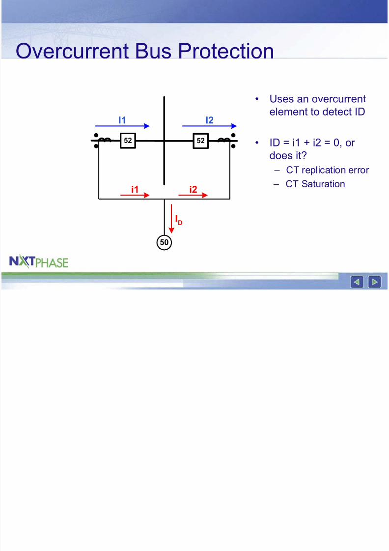
Overcurrent Bus Protection
• Uses an overcurrentelement to detect ID
• ID = i1 + i2 = 0, or
does it? – CT replication error
– CT Saturation
52 52
I1 I2
i1 i2
50
ID
8/3/2019 Testing Low Impedance
http://slidepdf.com/reader/full/testing-low-impedance 11/48
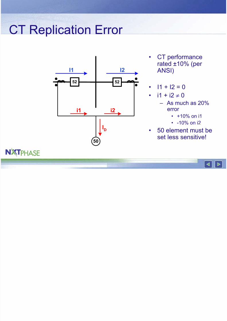
CT Replication Error
• CT performancerated ±10% (per ANSI)
• I1 + I2 = 0• i1 + i2 ≠ 0
– As much as 20%error
• +10% on i1• -10% on i2
• 50 element must beset less sensitive!
52 52
I1 I2
i1 i2
50
ID
8/3/2019 Testing Low Impedance
http://slidepdf.com/reader/full/testing-low-impedance 12/48
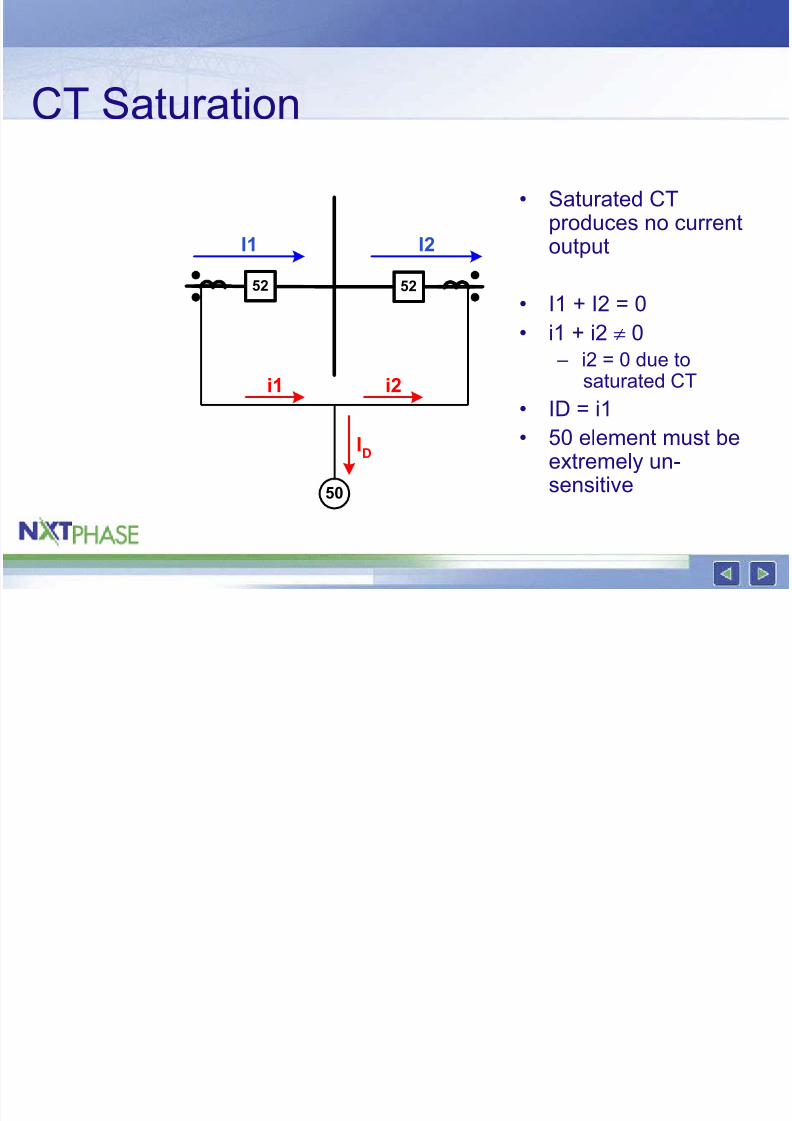
CT Saturation
• Saturated CTproduces no currentoutput
• I1 + I2 = 0• i1 + i2 ≠ 0
– i2 = 0 due tosaturated CT
• ID = i1• 50 element must be
extremely un-sensitive
52 52
I1 I2
i1 i2
50
ID
8/3/2019 Testing Low Impedance
http://slidepdf.com/reader/full/testing-low-impedance 13/48
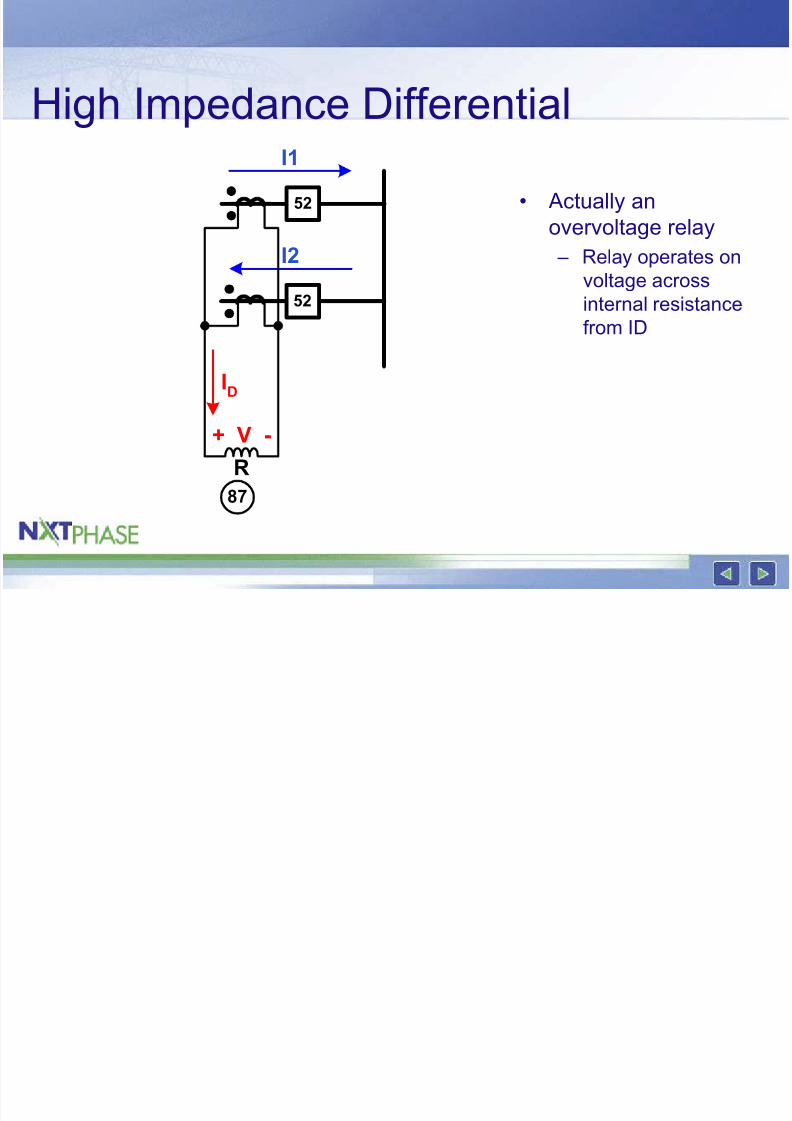
High Impedance DifferentialI1
I2
ID
52
52
87
+ V -
R
• Actually anovervoltage relay
– Relay operates on
voltage across
internal resistancefrom ID
8/3/2019 Testing Low Impedance
http://slidepdf.com/reader/full/testing-low-impedance 14/48
High Impedance Differential
• Pluses – Clever solution to
CT saturation
• High impedance
forces differential
current through
other CTs
• Voltage
developed is less
than that of internal fault
– Reliable
• Minuses – Dedicated CTs
– Matched
performance class
CTs – Identical CT ratios,
tapped at full ratio
8/3/2019 Testing Low Impedance
http://slidepdf.com/reader/full/testing-low-impedance 15/48
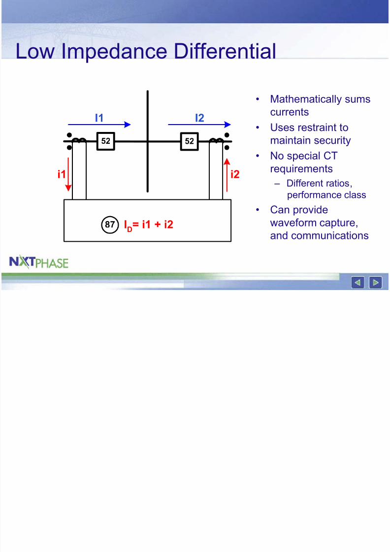
Low Impedance Differential
• Mathematically sumscurrents
• Uses restraint to
maintain security
• No special CTrequirements
– Different ratios,
performance class
• Can provide
waveform capture,
and communications
52 52
I1 I2
i1
87 ID= i1 + i2
i2
8/3/2019 Testing Low Impedance
http://slidepdf.com/reader/full/testing-low-impedance 16/48
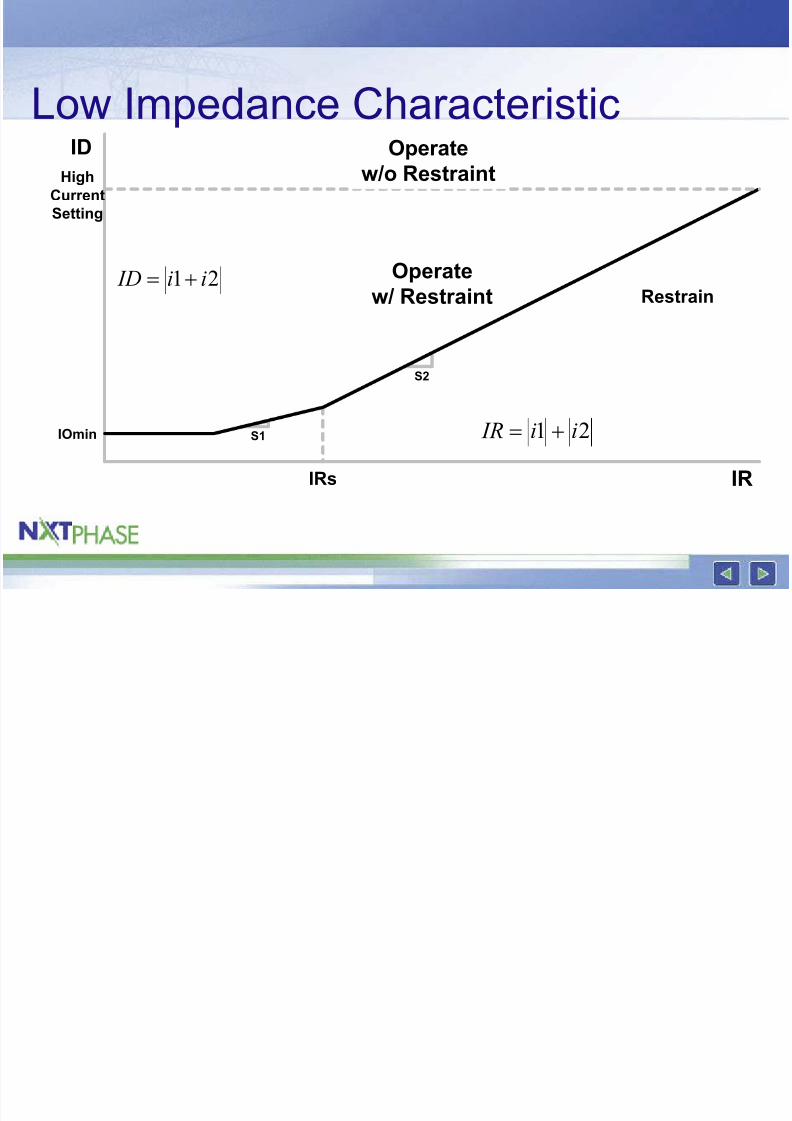
Low Impedance Characteristic
S2
S1
ID
IR
Operate
w/ Restraint
IRs
IOmin
High
Current
Setting
Restrain
Operate
w/o Restraint
21 ii ID +=
21 ii IR +=
8/3/2019 Testing Low Impedance
http://slidepdf.com/reader/full/testing-low-impedance 17/48
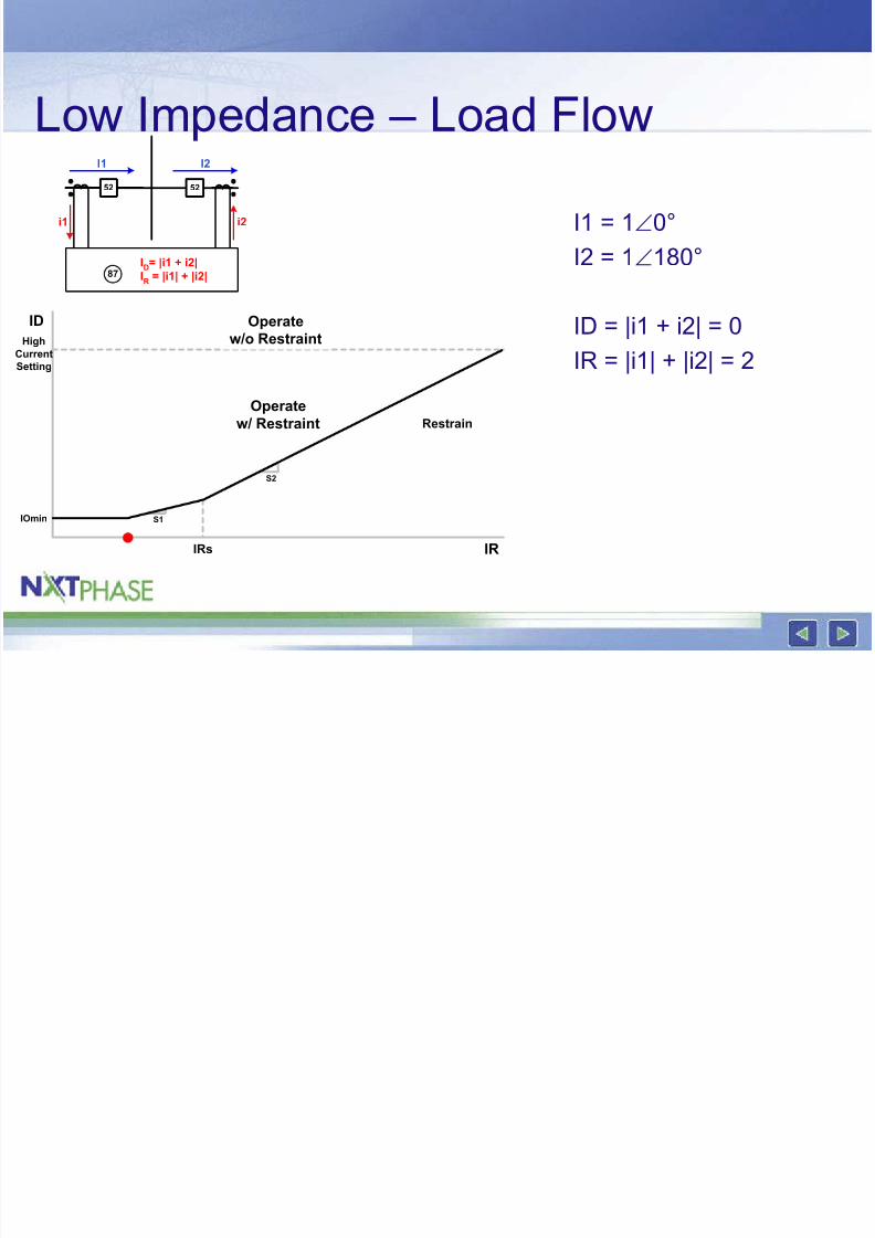
Low Impedance – Load Flow
I1 = 1∠0°I2 = 1∠180°
ID = |i1 + i2| = 0
IR = |i1| + |i2| = 2
S2
S1
ID
IR
Operate
w/ Restraint
IRs
IOmin
HighCurrent
Setting
Restrain
Operate
w/o Restraint
52 52
I1 I2
i1
87ID= |i1 + i2|
IR
= |i1| + |i2|
i2
8/3/2019 Testing Low Impedance
http://slidepdf.com/reader/full/testing-low-impedance 18/48
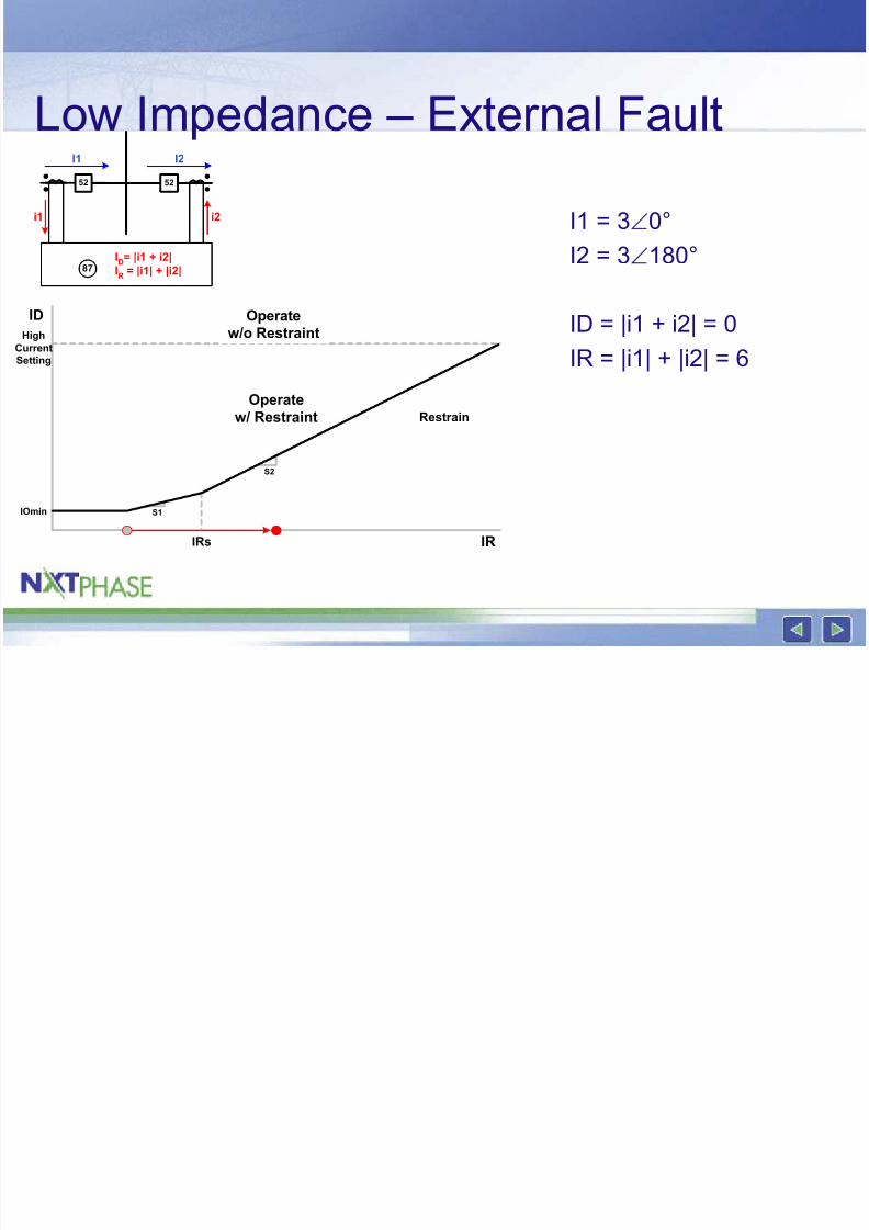
Low Impedance – External Fault
I1 = 3∠0°I2 = 3∠180°
ID = |i1 + i2| = 0
IR = |i1| + |i2| = 6
S2
S1
ID
IR
Operate
w/ Restraint
IRs
IOmin
High
Current
Setting
Restrain
Operate
w/o Restraint
52 52
I1 I2
i1
87ID= |i1 + i2|
IR
= |i1| + |i2|
i2
8/3/2019 Testing Low Impedance
http://slidepdf.com/reader/full/testing-low-impedance 19/48
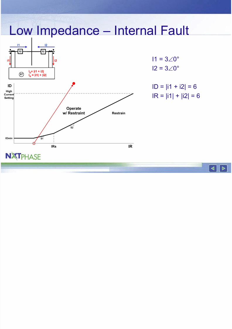
Low Impedance – Internal Fault
I1 = 3∠0°I2 = 3∠0°
ID = |i1 + i2| = 6
IR = |i1| + |i2| = 6
S2
S1
ID
IR
Operate
w/ Restraint
IRs
IOmin
HighCurrent
Setting
Restrain
52 52
I1 I2
i1
87ID= |i1 + i2|
IR
= |i1| + |i2|
i2
8/3/2019 Testing Low Impedance
http://slidepdf.com/reader/full/testing-low-impedance 20/48
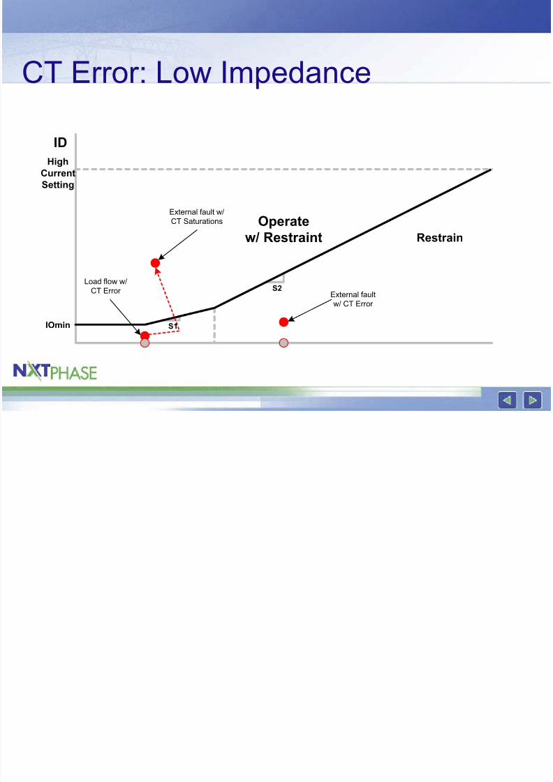
CT Error: Low Impedance
S2
S1
ID
Operatew/ Restraint
IOmin
High
Current
Setting
Restrain
Load flow w/
CT Error External fault
w/ CT Error
External fault w/
CT Saturations
8/3/2019 Testing Low Impedance
http://slidepdf.com/reader/full/testing-low-impedance 21/48
Low Impedance Relays
• NxtPhase B-PRO• GE B-30
• SEL 487B
• All use similar operating characteristic
• All use 6 inputs
8/3/2019 Testing Low Impedance
http://slidepdf.com/reader/full/testing-low-impedance 22/48
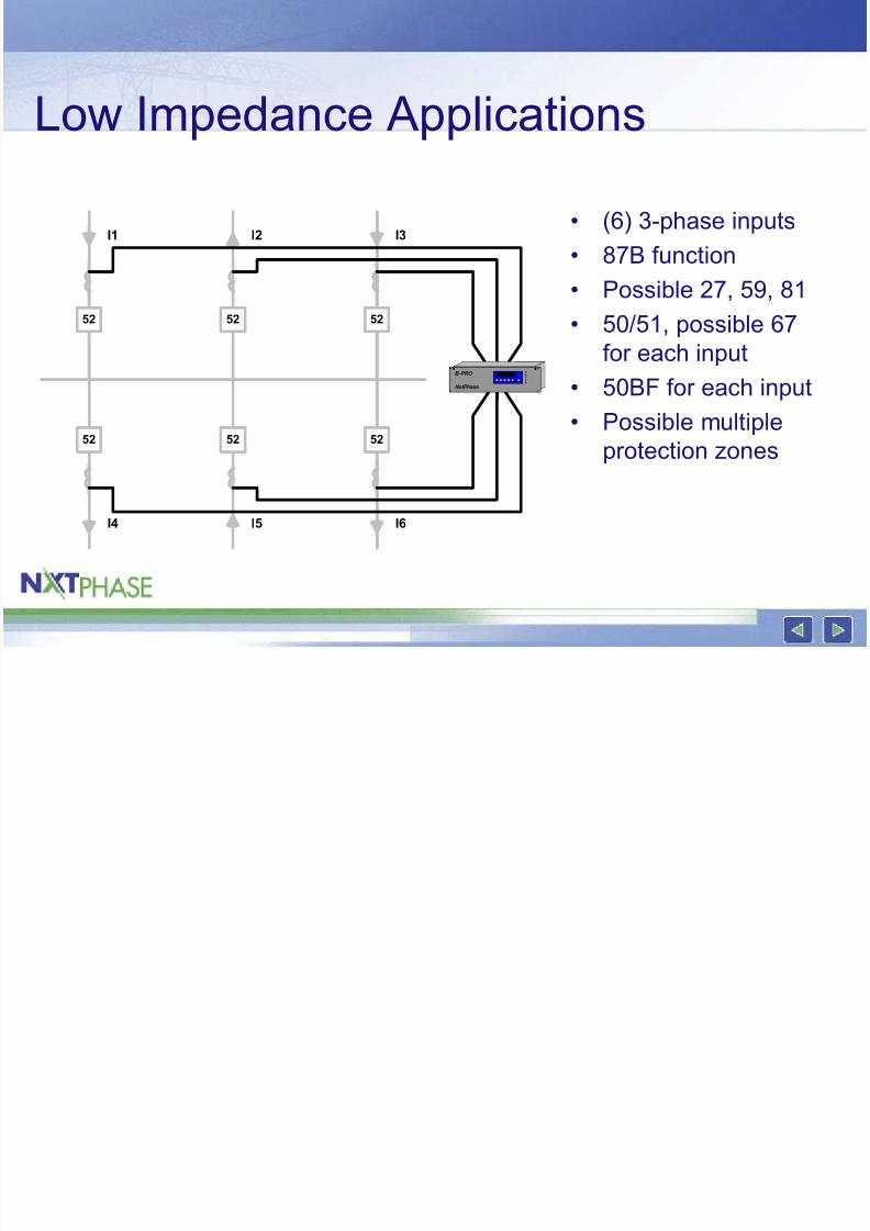
Low Impedance Applications
52 52 52
52 52 52
I1 I2 I3
I4 I5 I6
B-PRO
NxtPhase
• (6) 3-phase inputs• 87B function
• Possible 27, 59, 81
• 50/51, possible 67
for each input
• 50BF for each input
• Possible multiple
protection zones
8/3/2019 Testing Low Impedance
http://slidepdf.com/reader/full/testing-low-impedance 23/48
8/3/2019 Testing Low Impedance
http://slidepdf.com/reader/full/testing-low-impedance 24/48
Testing a Low Impedance Bus
Differential Relay
8/3/2019 Testing Low Impedance
http://slidepdf.com/reader/full/testing-low-impedance 25/48
4 Pieces of Knowledge
• How is the operating characteristicdefined?
– Curve equations
• How does the relay calculate ID and IR?• Does the characteristic work in amps or
per unit
• Relay settings
8/3/2019 Testing Low Impedance
http://slidepdf.com/reader/full/testing-low-impedance 26/48
GE B-30
• ID = |i1+i2+i3+i4+i5+i6|• IR = max (I1, I2, I3, I4, I5, I6)
• Per unit. Base is maximum primary
current on an input
8/3/2019 Testing Low Impedance
http://slidepdf.com/reader/full/testing-low-impedance 27/48
SEL 487B
• ID = |i1+i2+i3+i4+i5+i6|• IR = |i1|+…|i6|
• Per unit. Base is max CT ratio
8/3/2019 Testing Low Impedance
http://slidepdf.com/reader/full/testing-low-impedance 28/48
NxtPhase B-PRO
• ID = |i1+i2+i3+i4+i5+i6|• IR = (|i1|+…+|i6|)/2
• Per unit base on Bus MVA / Bus Voltage
8/3/2019 Testing Low Impedance
http://slidepdf.com/reader/full/testing-low-impedance 29/48
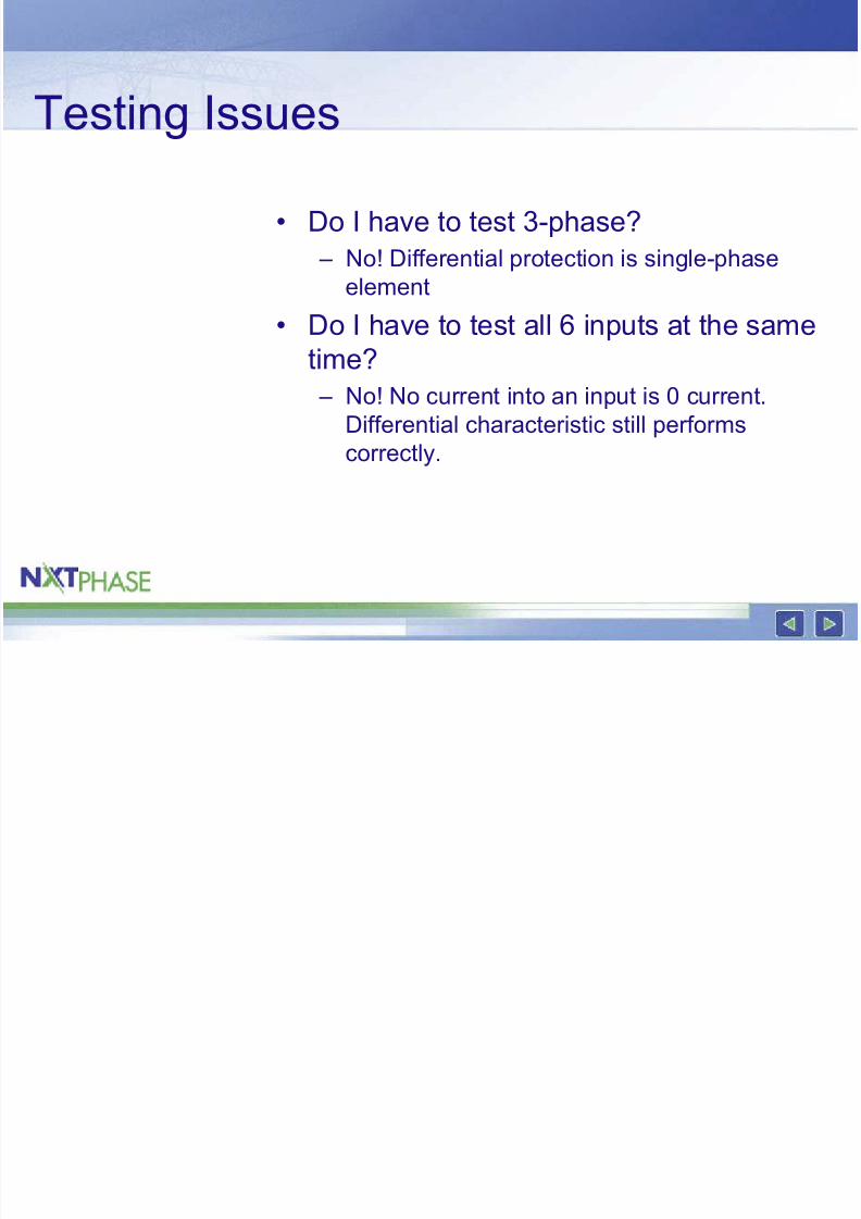
Testing Issues
• Do I have to test 3-phase? – No! Differential protection is single-phase
element
• Do I have to test all 6 inputs at the same
time?
– No! No current into an input is 0 current.
Differential characteristic still performs
correctly.
8/3/2019 Testing Low Impedance
http://slidepdf.com/reader/full/testing-low-impedance 30/48
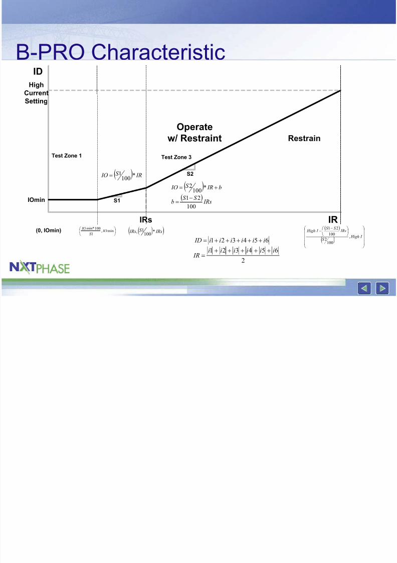
B-PRO Characteristic
S2
S1
ID
IR
Operate
w/ Restraint
IRs
IOmin
High
Current
Setting
Restrain
Test Zone 1 Test Zone 3
(0, IOmin)
min,
1
100min* IO
S
IO ( )( ) IRsS IRs *1001,
( )
( )
−−
I HighS
IRsS S
I High
,
1002
100
21
( ) IRS IO *1001=
( ) b IRS IO += *100
2
( ) IRs
S S b
100
21−=
2
654321 iiiiii IR
+++++=
654321 iiiiii ID +++++=
8/3/2019 Testing Low Impedance
http://slidepdf.com/reader/full/testing-low-impedance 31/48
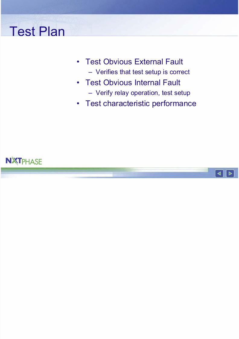
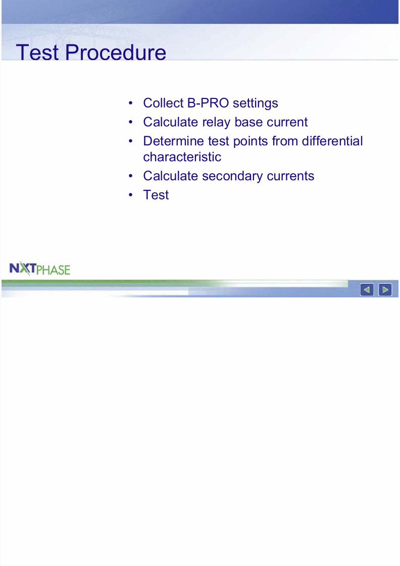
Test Plan
• Test Obvious External Fault – Verifies that test setup is correct
• Test Obvious Internal Fault
– Verify relay operation, test setup• Test characteristic performance
8/3/2019 Testing Low Impedance
http://slidepdf.com/reader/full/testing-low-impedance 32/48
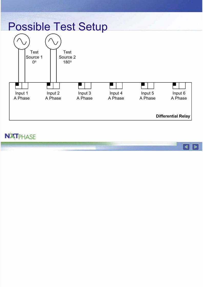
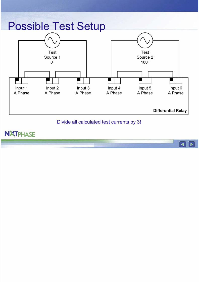
Possible Test Setup
Differential Relay
Input 2
A Phase
Input 3
A Phase
Input 1
A Phase
Input 5
A Phase
Input 6
A Phase
Input 4
A Phase
TestSource 1
0o
TestSource 2
180o
8/3/2019 Testing Low Impedance
http://slidepdf.com/reader/full/testing-low-impedance 33/48
Possible Test Setup
Divide all calculated test currents by 3!
Differential Relay
Input 2
A Phase
Input 3
A Phase
Input 1
A Phase
Input 5
A Phase
Input 6
A Phase
Input 4
A Phase
TestSource 1
0o
TestSource 2
180o
8/3/2019 Testing Low Impedance
http://slidepdf.com/reader/full/testing-low-impedance 34/48
8/3/2019 Testing Low Impedance
http://slidepdf.com/reader/full/testing-low-impedance 35/48
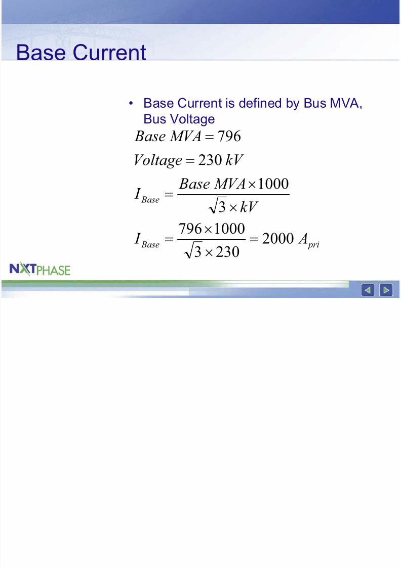
Base Current
• Base Current is defined by Bus MVA,Bus Voltage
pri Base
Base
A I
kV
MVA Base I
kV Voltage
MVA Base
20002303
10007963
1000
230
796
=×
×=
×
×=
=
=
8/3/2019 Testing Low Impedance
http://slidepdf.com/reader/full/testing-low-impedance 36/48
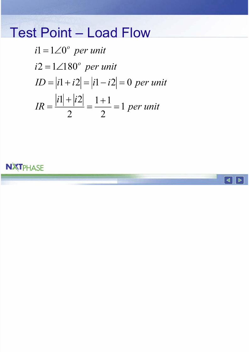
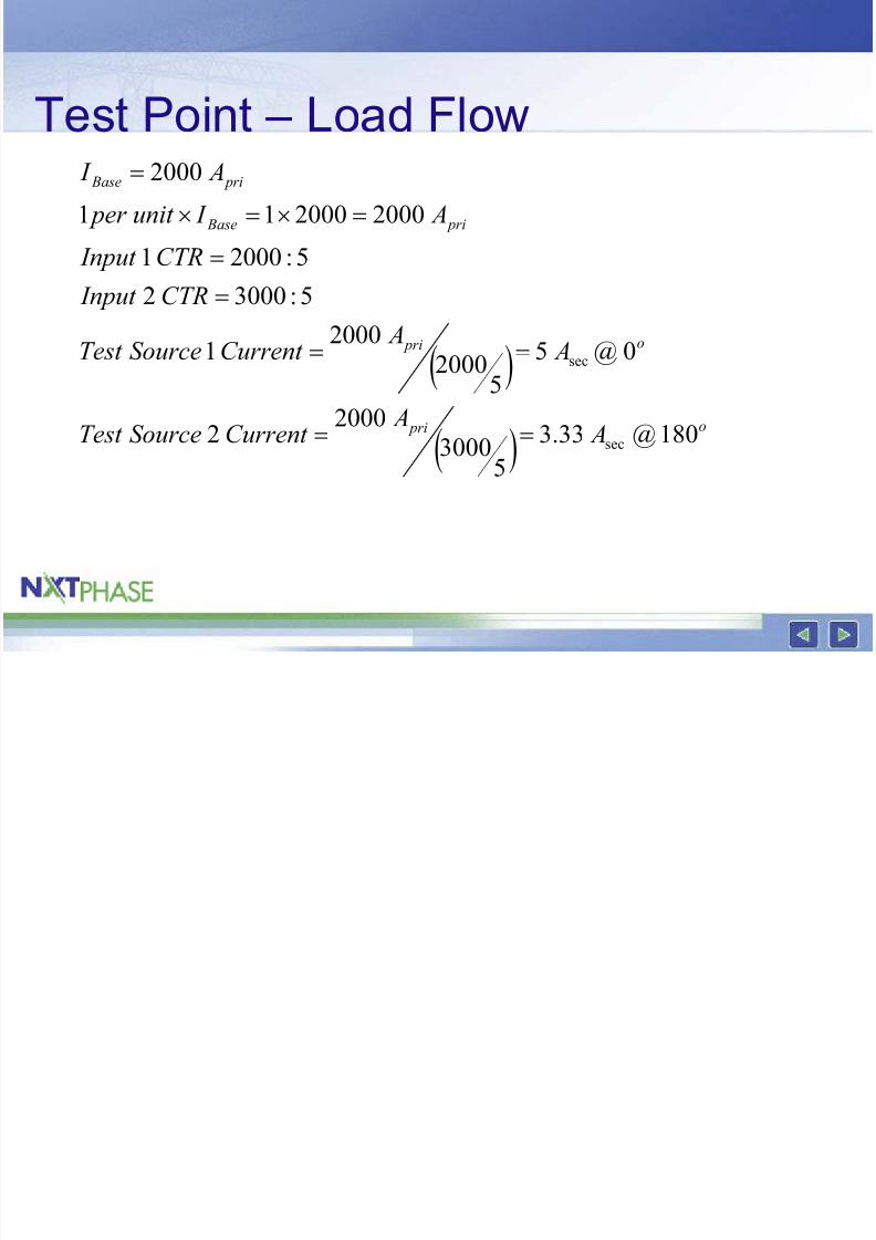
Test Point – Load Flow
unit per ii IR
unit per iiii ID
unit per i
unit per i
o
o
12
11
2
21
02121
18012
011
=+=+=
=−=+=∠=
∠=
8/3/2019 Testing Low Impedance
http://slidepdf.com/reader/full/testing-low-impedance 37/48
Test Point – Load Flow
( )
( )
o pri
o pri
pri Base
pri Base
A A
Current SourceTest
A ACurrent SourceTest
CTR Input
CTR Input
A I unit per
A I
53000
20002
0@55
200020001
5:30002
5:20001
2000200011
2000
sec
sec
==
==
=
=
=×=×
=
8/3/2019 Testing Low Impedance
http://slidepdf.com/reader/full/testing-low-impedance 38/48
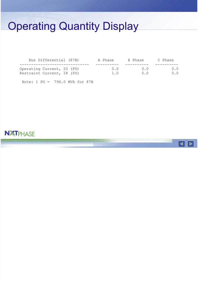
Operating Quantity Display
Bus Differential (87B) A Phase B Phase C Phase
------------------------------ ---------- ---------- ----------
Operating Current, IO (PU) 0.0 0.0 0.0
Restraint Current, IR (PU) 1.0 0.0 0.0
Note: 1 PU = 796.0 MVA for 87B
8/3/2019 Testing Low Impedance
http://slidepdf.com/reader/full/testing-low-impedance 39/48
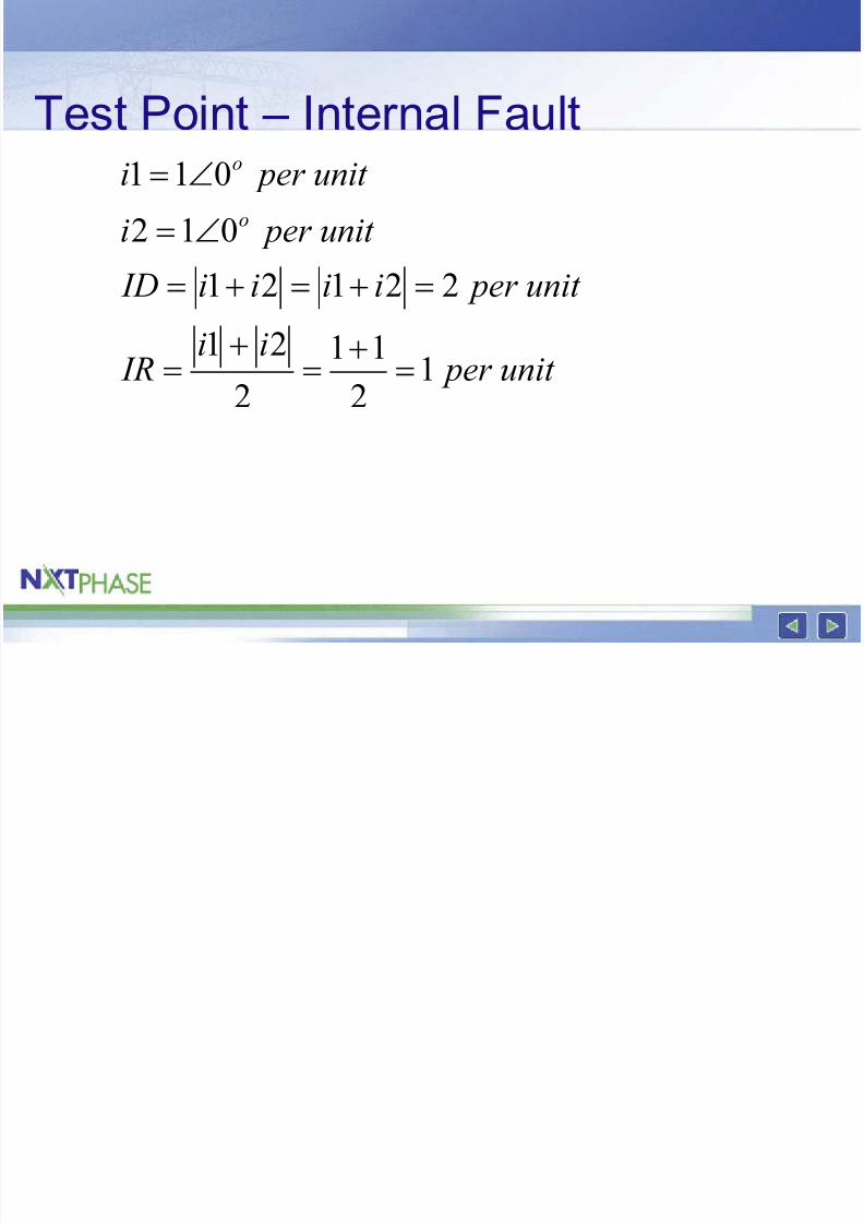
Test Point – Internal Fault
unit per ii IR
unit per iiii ID
unit per i
unit per i
o
o
1211
221
22121
012
011
=+=+=
=+=+=∠=
∠=
8/3/2019 Testing Low Impedance
http://slidepdf.com/reader/full/testing-low-impedance 40/48
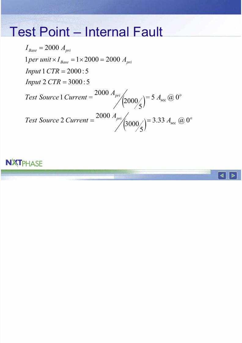
Test Point – Internal Fault
( )
( )
o pri
o pri
pri Base
pri Base
A A
Current SourceTest
A A
Current SourceTest
CTR Input
CTR Input
A I unit per
A I
53000
20002
0@55
2000
20001
5:30002
5:20001
2000200011
2000
sec
sec
==
==
=
=
=×=×
=
8/3/2019 Testing Low Impedance
http://slidepdf.com/reader/full/testing-low-impedance 41/48
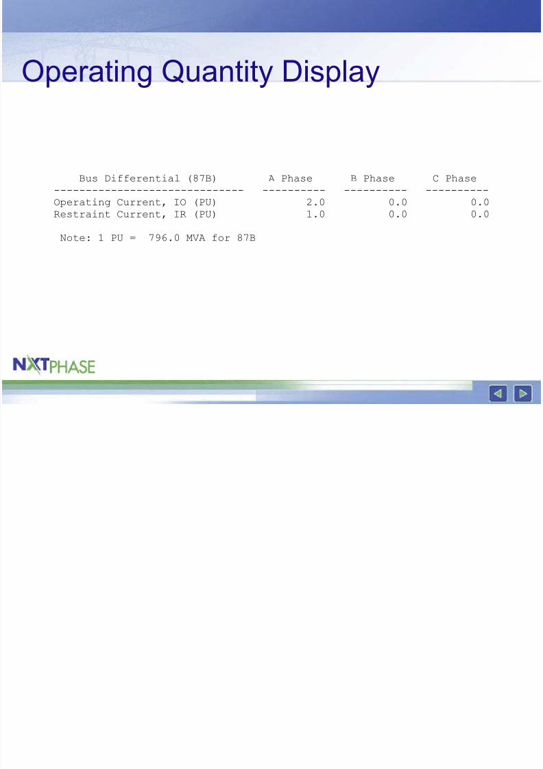
Operating Quantity Display
Bus Differential (87B) A Phase B Phase C Phase
------------------------------ ---------- ---------- ----------
Operating Current, IO (PU) 2.0 0.0 0.0
Restraint Current, IR (PU) 1.0 0.0 0.0
Note: 1 PU = 796.0 MVA for 87B
8/3/2019 Testing Low Impedance
http://slidepdf.com/reader/full/testing-low-impedance 42/48
Testing the characteristic
• Why can’t you start with an externalfault, and vary 1 current until the relay
operates?
• Answer…
8/3/2019 Testing Low Impedance
http://slidepdf.com/reader/full/testing-low-impedance 43/48
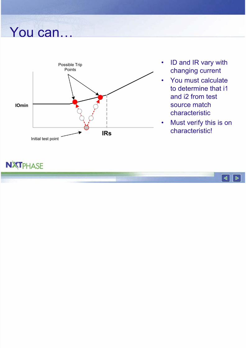
You can…
• ID and IR vary withchanging current
• You must calculate
to determine that i1
and i2 from testsource match
characteristic
• Must verify this is on
characteristic!IRs
IOmin
Initial test point
Possible TripPoints
8/3/2019 Testing Low Impedance
http://slidepdf.com/reader/full/testing-low-impedance 44/48
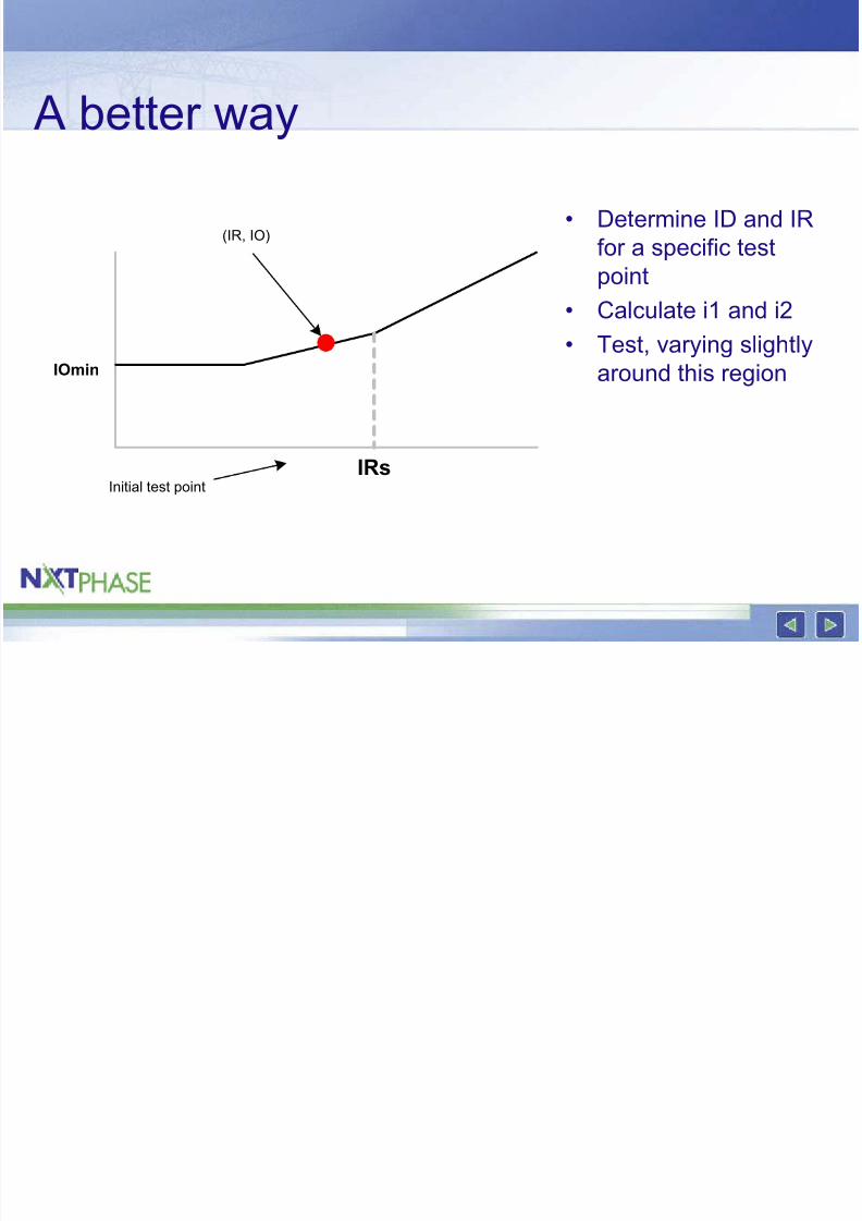
A better way
• Determine ID and IRfor a specific test
point
• Calculate i1 and i2
• Test, varying slightlyaround this region
IRs
IOmin
Initial test point
(IR, IO)
8/3/2019 Testing Low Impedance
http://slidepdf.com/reader/full/testing-low-impedance 45/48
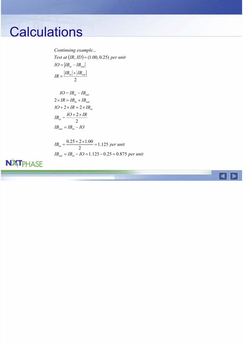
Calculations( )
unit per IO IB IB
unit per IB
IO IB IB
IR IO IB
IB IR IO
IB IB IR
IB IB IO
IB IB IR
IB IB IO
unit per ID IRat Test
exampleContinuing
inout
in
inout
in
in
out in
out in
out in
out in
875.025.0125.1
125.12
00.1225.0
2
2
22
2
2
)25.0,00.1(,
...
=−=−=
=×+
=
−=
×+=
×=×+
+=×
−=
+=
−=
=
8/3/2019 Testing Low Impedance
http://slidepdf.com/reader/full/testing-low-impedance 46/48
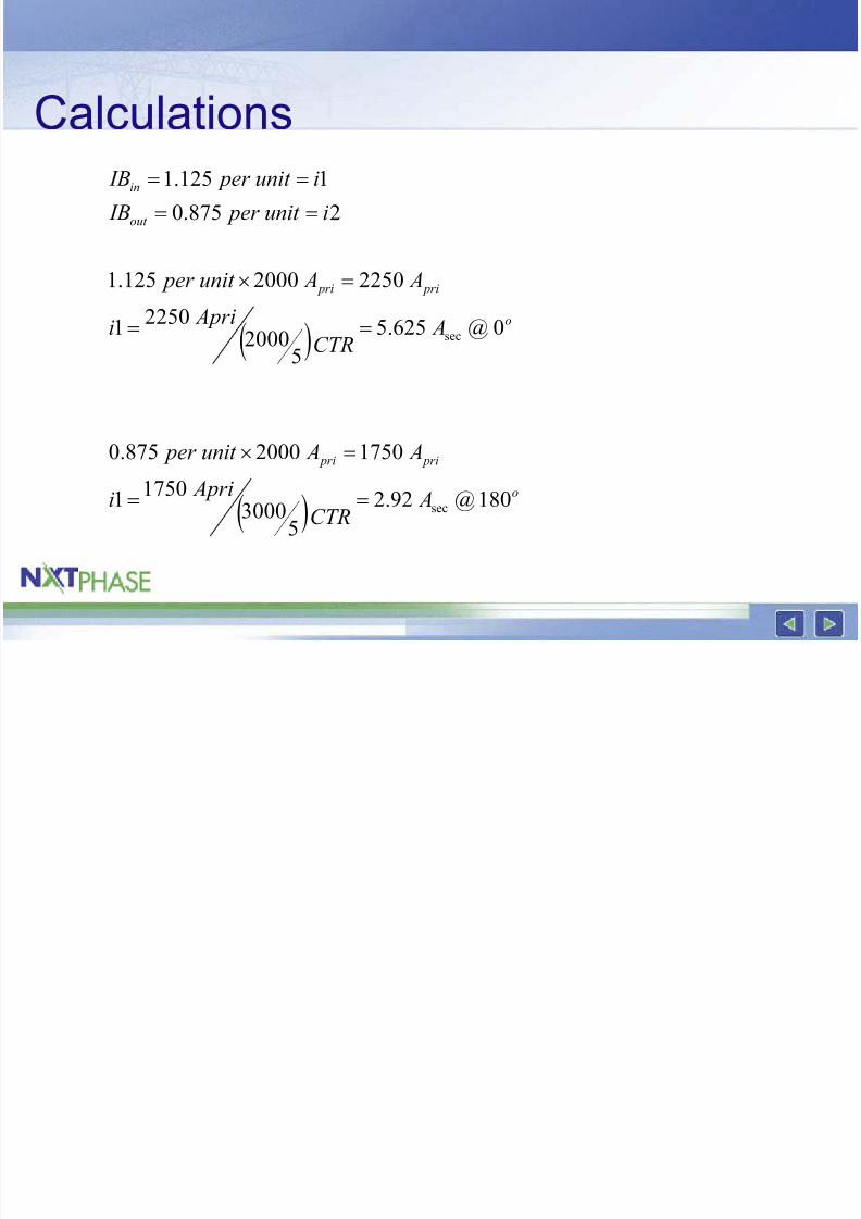
Calculations
( )
( )o
pri pri
o
pri pri
out
in
ACTR
Aprii
A Aunit per
ACTR
Aprii
A Aunit per
iunit per IB
iunit per IB
53000
17501
17502000875.0
52000
22501
22502000125.1
2875.0
1125.1
sec
sec
==
=×
==
=×
==
==
8/3/2019 Testing Low Impedance
http://slidepdf.com/reader/full/testing-low-impedance 47/48
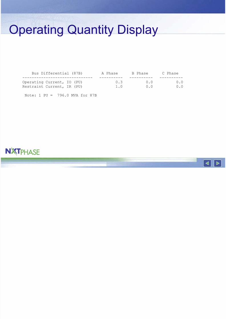
Operating Quantity Display
Bus Differential (87B) A Phase B Phase C Phase
------------------------------ ---------- ---------- ----------
Operating Current, IO (PU) 0.3 0.0 0.0
Restraint Current, IR (PU) 1.0 0.0 0.0
Note: 1 PU = 796.0 MVA for 87B
8/3/2019 Testing Low Impedance
http://slidepdf.com/reader/full/testing-low-impedance 48/48
Summary
• Low impedance bus differential is easyto apply
• Testing
– 1 phase okay – 2 inputs only okay
– Must understand operating characteristic
– Have to remember per unit calculations!


![ALUMINUM ELECTROLYTIC CAPACITORS · 2010-01-13 · 59 SX [ For Low Impedance & Low E.S.R ]2,000~5,000hrs. at 105°C 63 SY [ For Low Impedance and Low E.S.R Suitable for Output of](https://img.pdfslide.net/doc/110x75/5e73a82112217f1b2823b4e2/aluminum-electrolytic-capacitors-2010-01-13-59-sx-for-low-impedance-low.jpg)