Embed Size (px)
Citation preview

Testing of Continuous Sampling Air-ICP and Mercury Systems as Continuous Emission Monitors at the
Diagnostic Instrumentation and Analysis Laboratory
September 18-26, 2000
D. P. Baldwin, S. J. Bajic, D. E. Eckels, and D. S. Zamzow, Ames Laboratory, and G. P. Miller, S. Tao, and C. A. Waggoner, DIAL
Ames Laboratory-USDOE
Report IS-5144 February 15, 2001
Revised, March 15, 2001

Introduction This report has been prepared to document the performance of the continuous sampling
reduced-pressure air-ICP-AES (inductively coupled plasma - atomic emission spectroscopy) and
mercury-monitor systems developed by Ames Laboratory for use as continuous emission
monitors (CEM). This work was funded by the U. S. Department of Energy, Office of
Environmental Management, Office of Science and Technology, through the Mixed Waste Focus
Area. The purpose of the project is to develop instrumentation and methods for spectroscopic
field monitoring applications. During FY00 this included continued work on the development of
the continuous sample introduction system and the multi-frequency AOTF-echelle spectrometer,
used in conjunction with the reduced-pressure air-ICP-AES system as a multi-metal CEM. The
assembly, development, and testing of an echelle spectrometer system for the detection of
mercury (Hg) by atomic absorption was also completed during FY00. The continuous sampling
system and the multi-metal air-ICP and mercury-monitor CEM systems were tested at
Mississippi State University at the Diagnostic Instrumentation and Analysis Laboratory (DIAL)
at the end of FY00. This report describes the characteristics and performance of these systems,
and the results of the field tests performed at DIAL.
The continuous sampling air-ICP and mercury-monitor CEM systems are being
developed in response to the need of DOE and other organizations to monitor the heavy-metal or
radioactive materials that may be released during the processing or combustion of hazardous or
mixed-waste materials. The air-ICP system has been designed for the on-line detection and
monitoring of heavy metals (beryllium, cadmium, chromium, and lead, in particular) in process
or exhaust gas streams by optical emission spectroscopy. Due to the relatively poor limits of
detection for Hg by optical emission techniques, the mercury-monitor CEM has been designed
specifically for the detection of elemental Hg by optical absorption. A heated pyrolysis tube is
used in this system to convert oxidized Hg compounds to elemental Hg prior to analysis, for the
determination of total mercury in the gas sample stream. The promulgation of regulations
limiting the release of these metals and requiring continuous monitoring of stack gases from
combustion and treatment processes would seriously impact the operations of DOE waste
incinerators and other facilities. Therefore, it is important to develop and validate techniques
that adequately meet proposed sensitivity and accuracy requirements. The most likely form of
validation for such a technique will involve comparison of CEM results for a test combustion
2

system with EPA Reference Method 29 (RM-29).1 Therefore, the air-ICP and mercury-monitor
CEM systems were tested at DIAL by monitoring metal emissions in a fuel oil-air combustion
exhaust while simultaneously collecting samples using the RM-29 technique. The CEM results
were available continuously during the on-line monitoring that was performed. The results of
the RM-29 sampling were received a number of weeks after the testing at DIAL. These results
are discussed in this report, with a comparison and evaluation of the RM-29 and air-ICP and
mercury-monitor CEM data.
The continuous sampling reduced-pressure air-ICP-AES system was assembled and
tested at Ames Laboratory during FY99, and a field test of the system was conducted at the end
of FY99 at DIAL. The results for the FY99 test have been reported.2 For that test, the
continuous sampling system and reduced-pressure air-ICP were connected to a sampling port on
the DIAL “test-stand” (combustion system), and the system was operated as a CEM for metals
analysis while simultaneously collecting samples using RM-29. Reasonable agreement between
the continuous sampling air-ICP and RM-29 results were obtained for beryllium (Be), chromium
(Cr), and lead (Pb) during the FY99 test, using the echelle spectrometer system. Due to a failure
of the single-frequency AOTF in the AOTF-echelle spectrometer during the FY99 field test,
these results were obtained using a 0.2-m monochromator as a bandpass pre-filter for the echelle,
rather than the AOTF. For the FY00 test at DIAL, a multi-frequency AOTF, capable of selecting
three wavelength regions simultaneously to allow operation of the AOTF-echelle spectrometer as
a simultaneous multi-metals CEM, was used.3 This was the first field test of the multi-frequency
AOTF-echelle spectrometer. This spectrometer was used in conjunction with the reduced-
pressure air-ICP during the test at DIAL for simultaneous detection of the hazardous air pollutant
metals Be, cadmium (Cd), Cr, and Pb. After the air-ICP CEM tests, the continuous sampling
system was used in conjunction with the mercury-monitor system for the detection of Hg.
Laboratory testing of the mercury-monitor CEM system was conducted at Ames Laboratory
during FY00, and the work performed at DIAL was the first field test of the mercury system.
During the test at DIAL, RM-29 sampling was conducted concurrently with the operation of the
air-ICP and mercury-monitor CEM systems, to allow a comparison of the reference method and
CEM results.
3

Experimental
Continuous Sampling System A description of the continuous sampling system developed for this project has been
published,2,3 and is only summarized here. A schematic diagram of the system is shown in
Figure 1.
Differential Pressureand Thermocouple
Probes
Differential Pressureand Thermocouple
ProbesSampling Chamber
to Sampling Pump
to Air-ICP or Mercury CEM
Wall ofExhaust Stack
SamplingProbe
Sample Line
Nebulizer Spike(Air-ICP)
Room-Air Valve(Mercury CEM) Ballast
Figure 1. Schematic diagram of the continuous sampling system, with connection to an exhaust stack. Two heat-traced Teflon sample lines, one 12’ and one 24’ in length, were used to connect the sampling chamber to the sampling probe, inserted into the stack at DIAL.
The continuous sampling system is a dual-stage sampling system. A high-volume primary
sample (20-30 standard liters per minute, Lpm) is drawn isokinetically from a process pipe or
exhaust stack using a standard commercial EPA isokinetic glass-lined probe with an integral
heater (Apex Instruments). The sampling probe is connected to a commercial heat-traced Teflon
sample line (Technical Heaters), which is connected to the sampling chamber, a Teflon tube that
is 1”-inner diameter and 24” in length. A rotary vane pump (Gast Manufacturing model 0523-
V4-G180DX) draws gas through the sampling chamber in a laminar-flow arrangement, with over
95% of the sample being removed through an exit port and exhaust line at the end of the
chamber. On the inlet side of the sampling chamber, there are two ports (Teflon tees) that are
provided for connecting a differential pressure transducer (Validyne model P55D) and a Teflon-
coated thermocouple (Omega Engineering) to a Teflon differential pressure flow cell, so that the
gas flow rate and temperature of the primary sample can be monitored. For the test at DIAL, a
30-standard-Lpm sample was drawn from the stack, using the sampling pump. Two heat-traced
Teflon sample lines (attached in series for a total length of 36’) were used to connect the
sampling chamber (located inside the test facility at DIAL) to the stack sampling port (located
outside). The sampling probe, sample lines, and sampling chamber were operated at
4
approximately 110°C during the test at DIAL. To address the sample gas flow variations to the
axial channel of the air-ICP observed during the FY99 test, resulting from pressure fluctuations
in the exhaust line at DIAL,2 a ballast was added to the sampling system in FY00. The ballast is
a 6”-inner diameter, 3.5’-long PVC chamber having an internal volume of approximately 19.5 L.
The ballast is positioned next to the sampling chamber and connected to the exhaust line of the
sampling chamber, which is connected to the sampling pump. The sample gas stream does not
enter or flow through the ballast - only the exhaust line of the sampling chamber is connected to
the ballast. This arrangement provides for a reduction in pressure variations in the sampling
chamber resulting from pressure fluctuations in the stack, since the large-volume (19.5 L) ballast
damps the variations in the smaller-volume (approximately 0.3 L) sampling chamber. However,
even with the addition of the ballast, apparent air-ICP axial channel gas flow fluctuations (and
resulting ICP torch flicker) were observed during some of the FY00 air-ICP testing at DIAL, as
discussed below. However, during testing of the mercury-monitor system, no significant flow
fluctuations were observed at the gas flow gauge (oil-filled manometer) on the outlet side of the
sampling chamber.
A secondary sample is drawn isokinetically from the gas flowing through the sampling
chamber using a 1/4”-outer diameter Teflon sampling tube that is inserted approximately 4” into
the end of the chamber. The tube currently used has a 0.170”-inner diameter, with a 30° taper at
the sampling end. The secondary sample outlet is connected to a 1/4” Teflon Swagelok tee. The
in-line port of this tee is followed by another Teflon differential pressure flow cell, to monitor
the sample flow rate from the sampling chamber. A Teflon-coated thermocouple (Omega) is
inserted into the inlet of this flow cell to measure the gas temperature. The differential pressure
is monitored using an oil-filled manometer (Dwyer Instrument model 101) that has a maximum
range of 0.5” of water. The primary flow cell, Teflon sampling chamber, and secondary flow
cell are heat-traced using electrical heat tape and insulation wrap. For the reduced-pressure air-
ICP system, a rotary vane pump (Gast Manufacturing model 1023-101Q-G608X) is used to draw
a slight vacuum on the ICP metal enclosure, drawing a sample flow of approximately 1 standard
Lpm out of the sampling chamber, for introduction into the axial channel of the ICP. For the
mercury-monitor system, a linear pump (Gast Manufacturing model SPP-6GAS-101) is used to
draw a sample flow of approximately 1 standard Lpm from the sampling chamber, for
introduction into a 1-m absorption cell. The secondary gas sample drawn from the sampling
5

chamber is introduced into either the reduced-pressure air-ICP or the mercury-monitor system
for the detection of hazardous air pollutant metals.
Reduced-Pressure Air-ICP and Multi-Frequency AOTF-Echelle Spectrometer CEM The reduced-pressure air-ICP-AES system used for multi-metals emission monitoring has
been described in detail previously,2,3 although some modifications have been made to the
system. A photograph of the ICP metal enclosure is shown in Figure 2.
Figure 2. Photograph of the reduced-pressure air-ICP system, showing the air plasma inside the metal enclosure, part of the connection to the ICP auto-matching network (inside the wire mesh screen on the right), and the front-end of the AOTF-echelle spectrometer (on the left).
The system consists of an air-ICP that is operated at reduced pressure inside a 6”-diameter metal
enclosure, the continuous sampling system, and the AOTF-echelle spectrometer. The bottom
flange of the metal enclosure has gas-line connections for the ICP torch plasma and auxiliary gas
supplies and for the ICP axial channel (sample) gas, which is connected to the Teflon sampling
chamber. A connection point for the Tesla coil discharge required to ignite the ICP is included
on the bottom flange of the enclosure. An additional gas-line connection on the bottom flange is
provided for the introduction of supplemental air (approximately 50 Lpm), which provides some
cooling of the metal enclosure during operation of the 3-kW air plasma. Above the ICP torch,
1/4”-diameter stainless steel tubing is welded onto the 6”-diameter metal enclosure, for water-
cooling of the upper portion of the enclosure. At the top of the enclosure, 1.5”-diameter stainless
steel and copper tubing is connected; water-cooling of this tubing is also provided to reduce the
gas temperature of the ICP exhaust to less than 50°C prior to reaching the chamber pump. The
chamber pump is connected to this 1.5”-diameter tubing to operate the enclosure at reduced
6

pressure, 0 to -5 psig, in order to draw sample continuously into the plasma, from the Teflon
sampling chamber, through the axial channel of the ICP torch. This pump has replaced the Roots
blower, used in FY99, to decrease the overall size of the reduced-pressure air-ICP system. The
ICP load coil (a 5-turn coil) is connected to the auto-matching network (Seren Industrial Power
Systems solid-state, 27 MHz, 3-kW ICP system) using copper tubing feed-throughs in a Delrin
flange on the right side of the metal enclosure.2,3 The plasma is generated using argon gas at
approximately 1-kW RF power and then switched over to air operation, completely replacing the
argon with air and increasing the RF power to approximately 3-kW.
Optical emission signals from metals introduced into the air-ICP are detected using the
AOTF-echelle spectrometer. A 2”-diameter, 3” focal-length fused silica lens, mounted in the
flange on the left side of the ICP enclosure, forms a 1:1 image of the plasma at the input aperture
of the AOTF-echelle spectrometer. A quartz AOTF (MVM Electronics) placed between two
crossed polarizers (Casix model PGT8208 α-BBO Glan-Taylor polarizers) acts as an order-
sorting pre-filter for the echelle. An RF frequency applied to the AOTF selects a narrow band
(approximately 1-nm bandwidth) of optical emission from the ICP, which is introduced into the
echelle. The bandpass of the AOTF is smaller than the width (free spectral range) of one order
of the echelle grating, so no cross-dispersing optical element such as a prism or grating is
required in the echelle spectrometer. This AOTF provides the capability of multi-wavelength
simultaneous operation, since a multi-frequency RF driver is incorporated into the system. This
allows for monitoring ICP emission signals from multiple elements simultaneously. The
collimating and focusing mirrors in the current AOTF-echelle spectrometer are 0.4-m focal-
length off-axis parabolic mirrors (Atlantis Optical Laboratories, Inc.), not the 0.38-m focal-
length concave spherical mirrors used in the previous system.4 The detector is a two-stage
thermoelectrically cooled CCD (Hamamatsu model S7032-1007).
For the test at DIAL, data acquisition for the metals Be, Cd, Cr, and Pb was generally
performed in a sequential, multi-element fashion, collecting data for Be and Cr in one data set
and Cd and Pb in the following data set (switching the AOTF operating frequencies between data
sets), at approximately 10 points per minute. Initial calibration of the air-ICP system was
performed by introducing aqueous solution standards of metals (Be, Cd, Cr, and Pb at varying
concentrations) into a CETAC Technologies U5000-AT ultrasonic nebulizer (USN). The dry
aerosol output from the USN was introduced into a tee on the inlet side of the 12’ Teflon sample
7

line connected to the sampling chamber (Nebulizer Spike in Figure 1), with one port of the tee
open to room air. This arrangement was used for introducing metal aerosols into the sampling
chamber and the air-ICP system for calibration and monitoring experiments with the stack not
connected. After calibration, the system was connected to the stack at DIAL, for acquisition of
stack-metals monitoring data. Since the USN was used for the introduction of metal aerosols
into the stack, on-line metals standard additions, similar to those performed during the FY99 test,
were not done.2 Instead, the response of the air-ICP AOTF-echelle system was checked at
various intervals by comparing the calibration of the system against the initial non-stack-
connected calibration curves.
Mercury-Monitor CEM A mercury-monitor CEM system was assembled and tested during FY00 at Ames
Laboratory and used for stack-mercury monitoring during the field test at DIAL. Elemental
mercury is detected by atomic absorption in a 1-m pathlength absorption cell, using a mercury
pen lamp as the source and a 0.38-m focal-length echelle spectrometer with a photodiode array
(PDA) as the detector. This echelle spectrometer has no cross-dispersing optical element or
order-sorting pre-filter, so all orders of the echelle grating are spatially superimposed at the
detector. This spectrometer provides simultaneous detection of all of the strong Hg lines from
253-579 nm from the mercury pen lamp (diffracted from different orders of the echelle grating),
without spectral overlap of these lines at the detector, as shown in Figure 3.
0 500 1000Pixel Number
Hg
(I) 5
76.9
6H
g (I)
404
.65
Hg
(I) 2
53.6
5
Hg
(I) 4
35.8
3H
g (I)
296
.73
Hg
(I) 3
12.5
7, H
g (I)
579
.07
Hg
(I) 3
13.1
55, H
g (I)
313
.184
Hg
(I) 3
65.0
2
Hg
(I) 3
65.4
8
Hg
(I) 5
46.0
7H
g (I)
253
.65
Inte
nsity
(arb
. uni
ts)
Figure 3. Mercury pen lamp spectrum, obtained using the Hg-echelle spectrometer.
The Hg (I) 253.65-nm line is used to measure absorption due to mercury in the 1-m cell. Other
Hg lines (non-ground-state electronic transitions not subject to mercury absorption) can be used
8
to correct for light source intensity fluctuations, light scattering by particles, and absorption due
to species other than Hg. Since all the mercury lines can be monitored simultaneously, this
system in effect provides a dual-beam (or “multiple-beam”) optical arrangement with a reference
channel, using only a single light source, absorption cell, spectrometer, and detector. A
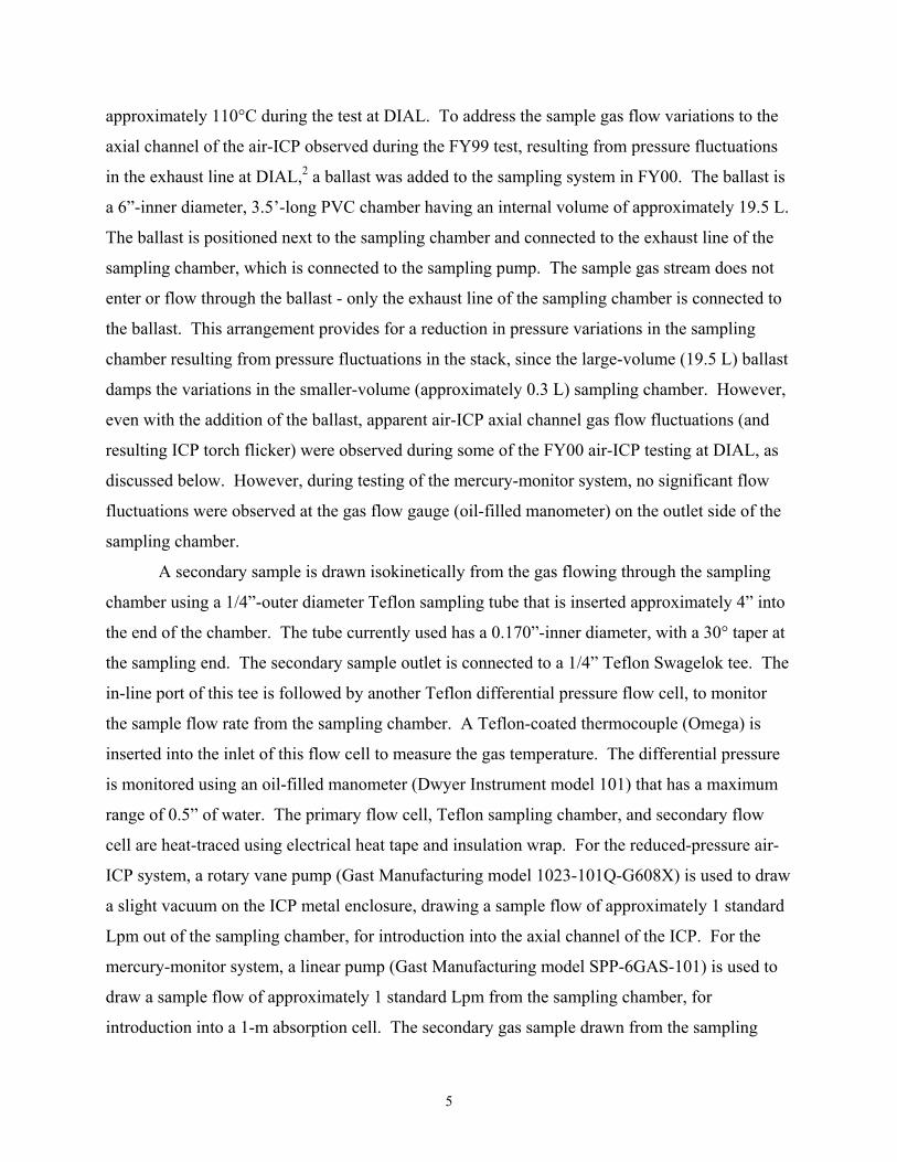
schematic diagram and a photograph of the mercury-monitor CEM are shown in Figure 4.
1-m Absorption Cell
EchelleSpectrometer
MercuryPen Lamp
Sampling Chamber
Tube FurnacewithPyrolysis Tube
from StackRoom Air
VICI Dynacalibratorwith MercuryPermeation Tube
Sample Pump (1 Lpm)
to Exhaust
PDA
Figure 4. Schematic diagram and photograph of the mercury-monitor CEM system. In the photograph, the 1-m absorption cell is inside the 4’-long insulated tube (2), mounted on the metal frame, along with the mercury pen lamp (1, left side), optics, and 0.38-m echelle spectrometer (3, right side) with PDA detector. The Teflon sampling chamber is inside the 4’-long insulated tube (4), on top of the table. The sample pump draws gas out of the sampling chamber, through the pyrolysis tube in the tube furnace (5), and through the absorption cell.
Light from a mercury pen lamp (Oriel model 6035 Hg(Ar) lamp operated at 10-mA AC
current, using an Oriel model 6060 power supply) is collected using a 1”-diameter, 6”-focal
length fused silica lens, with the lamp emission approximately collimated through the 1-m
absorption cell. The lamp is housed in an aluminum block, heated to 35°C using a cartridge
heater (Omega Engineering model CIR-1031/120) and temperature controller (Valco Instruments
model ITC10399). The absorption cell has quartz windows, and is heated to approximately
125°C using electrical heat tape inside an insulated tube (Accessible Products Company). Light
that passes through the cell passes through BG-24A and WG-280 optical filters (Schott Glass
Technologies - to attenuate the Hg (I) 253.65- and 546.07-nm lines with respect to the other Hg
lines) prior to being focused onto the entrance slit of the echelle spectrometer, using a 1”-
diameter, 6”-focal length fused silica lens. This spectrometer is a modified version of the 0.38-m
echelle spectrometer described previously.4 The optics in this echelle consist of a 1”-diameter
flat turning mirror, two 2”-diameter 0.38-m focal-length concave spherical mirrors (Optics for
Research) used as the collimating and focusing mirrors, the grating (Richardson Grating
9

Laboratory model 35-13-19-417 echelle, 52.67 grooves per mm, 69° blaze angle), and a 2”-
diameter flat turning mirror. The PDA is an EG&G Princeton Applied Research model 1453
detector.
Sample stack gas is introduced into the mercury-monitor CEM using the continuous
sampling system described above. A linear pump is used to draw a sample flow of
approximately 1 standard Lpm from the Teflon sampling chamber, through a heated pyrolysis
tube, and through the 1-m absorption cell. The pyrolysis tube is a 1”-diameter, 22”-long quartz
tube, filled with 0.25”-long quartz rings cut from 6-mm OD tubing, that is positioned inside the
tube furnace (Lindberg/BlueM model TF55030A, operated at 1000°C). The pyrolysis tube is
used for thermal decomposition of oxidized Hg compounds to elemental Hg, prior to
introduction into the absorption cell.5,6 The 1/4”-OD Teflon tubing that connects the sampling
chamber to the pyrolysis tube in the tube furnace and to the absorption cell is heat-traced using
electrical heating tape and operated at approximately 60°C. A two-way valve is inserted
between the sample line and the sampling chamber (see Figure 1) to allow stack gas sampling or
zero-checks to be performed. When performing zero-checks, room air (rather than stack gas) is
drawn into the sampling chamber and the 1-m absorption cell, by valving off the sample stream
from the combustion stack.
For the test at DIAL, mercury absorption was measured by ratioing the intensity for the
Hg (I) 253.65-nm line to that for the Hg (I) 546.07-nm line. Absorption by elemental mercury
vapor occurs at the 253.65-nm line, but not at the 546.07-nm line. Using both of these lines, an
improvement in the accuracy and stability of the system is achieved, since short- and long-term
fluctuations in the intensity output from the mercury lamp can be corrected for by using the
intensity ratio. This detection scheme also corrects for light scatter from particles in the
absorption cell, to the extent that this scattering is comparable at both 253.65- and 546.07-nm.
Prior to the introduction and analysis of the stack gas sample stream at DIAL, the mercury-
monitor CEM was calibrated by measuring the absorption resulting from the introduction of 8.71
µg/m3 Hg into the 1-m cell, from a permeation tube placed inside the Dynacalibrator (VICI
model 340-55B-YD). Interference at 253.65-nm due to absorption by sulfur dioxide (SO2) in the
stack gas sample was corrected during mercury-monitor data acquisition. The system was
calibrated by introducing a known concentration of SO2 into the 1-m cell (in the absence of Hg)
and measuring the absorption at 253.65- and 313.18-nm, using the intensity ratios (253.65-to-
10

546.07 and 313.18-to-546.07) for both of these lines. During stack sampling, a correction factor
to the measured 253.65-nm absorption was applied, based on the measured 313.18-nm SO2
absorption, to remove the 253.65-nm SO2 absorption contribution. During the test at DIAL, Hg
was introduced into the stack using the ultrasonic nebulizer (USN) at levels corresponding to
approximately 80 and 8 µg/m3. Hydrogen chloride (HCl) and SO2 gases were introduced at
approximately 100 and 50 ppmV, respectively, during the high-level testing (80 µg/m3 Hg) and
approximately 25 and 500 ppmV during low-level testing (8 µg/m3 Hg). During the test at
DIAL, mercury-monitor CEM data was acquired at a rate of approximately 20 points per minute.
Results and Discussion
DIAL Stack Operating Conditions During FY00, the combustion test-stand at DIAL was modified by extending the exhaust
line approximately ten meters, so that the RM-29 and CEM sampling ports were located outside
the facility. This modification allowed the combustion furnace to be operated at its optimum
conditions, rather than the fuel-lean conditions used in FY99 to minimize the gas temperature at
the sampling ports. During the FY00 test, the furnace was operated with 500 lb/hr of air and 32
lb/hr of fuel oil, which produced a gas flow in DIAL’s 6”-diameter, schedule-80 pipe of
approximately 4100 standard Lpm. At the sampling point, the gas temperature was 150°C, with
a velocity of approximately 6.1 m/s. The CEM and RM-29 sampling probes were installed in a
vertical section of the exhaust pipe, several meters downstream from the water-cooled exhaust
line. The probes were inserted into the stack through opposing ports with the probe nozzles
positioned in equivalent locations, within a few centimeters of each other (see Figure 5). This
arrangement minimizes differences in stack metals concentrations introduced into the CEM and
RM-29 systems. The equivalent nature of these opposing sampling positions has been
demonstrated previously by simultaneous collection of two sets of RM-29 samples using two
probes in this configuration. At the sampling point, the exhaust gas was flowing vertically down
the pipe.
In FY00, the USN was used (rather than the pneumatic air-driven stack nebulizer used in
FY99) for introducing appropriate concentrations of Be, Cd, Cr, and Pb (air-ICP) and Hg
(mercury-monitor CEM) into the exhaust stack gas. For the air-ICP testing, the USN output
aerosol was introduced into the stack at a port approximately five meters upstream from the
11

CEM and RM-29 sampling probes. For the mercury-monitor testing, the USN output aerosol
was introduced into the stack afterburner, slightly more than one meter above the sampling port,
so that the Hg in the aerosol would be vaporized and potentially oxidized after being introduced
into the stack. During RM-29 sampling, the air-ICP or mercury-monitor CEM systems were
used for on-line measurement of the stack-metals aerosol concentrations. The RM-29 collected
samples were sent to an analytical testing laboratory for quantitative analysis.
Figure 5. The combustion test-stand at DIAL, showing the port-locations used for the introduction of metal aerosols for the air-ICP and mercury-monitor CEM testing and for the introduction of SO2 and HCl gases during mercury-monitor testing. Sampling from the stack occurred on opposite sides of the same port, using one sampling probe for the air-ICP and mercury-monitor CEM systems and a second probe for RM-29 sampling.
SO2 and HCl Introduction
PrimaryBurner
Mercury Introduction
Air-ICP Metals Introduction
CEM and RM-29Sampling
Wall of Exhaust Stack
CEM Sampling Probe
RM-29 Sampling Probe
Gas
Flo
w
Reduced-Pressure Air-ICP and Multi-Frequency AOTF-Echelle Spectrometer CEM For the on-line detection of metals (Be, Cd, Cr, and Pb) using the reduced-pressure air-
ICP and multi-frequency AOTF-echelle spectrometer during the FY00 test at DIAL, significantly
different system performance was observed when the sampling system was connected to the
stack compared to the non-stack-connected results. When the sampling system was not
connected to the stack (during initial testing and calibration), the four metals Be, Cd, Cr, and Pb
were detected using the reduced-pressure air-ICP and AOTF-echelle system at levels
corresponding to approximately 5, 40, 10, and 50 µg/dscm, respectively. However, when the
sampling system was connected to the stack during RM-29 sampling (with metals introduced
into the stack at higher concentrations than the initial calibration detection limits), only Be was
detected. Some of the difference in system performance is thought to result from the use of
compromise ICP plasma conditions during some of the stack-sampling time periods. The
12

majority of the difference, however, is believed to result from an increase in the plasma emission
background that was not effectively removed from the emission signals for Be, Cd, Cr, and Pb
during stack sampling. In particular, the polarizers used with the quartz AOTF were not
adequate to eliminate the elevated plasma emission background signal during stack sampling,
which resulted in a significant degradation of the detection limits for Be, Cd, Cr, and Pb during
the test at DIAL.
In the AOTF-echelle spectrometer, the quartz AOTF is placed between crossed
polarizers.3,4 If the polarizers function properly, only light selected by the AOTF (which rotates
the polarization of the selected wavelength component in order to pass through the crossed
polarizers) reaches the echelle spectrometer and detector. The polarizers that were used during
the test at DIAL were ineffective in completely blocking the plasma background emission. The
polarizers used are designed to function well in the 200-400 nm wavelength range (in the
ultraviolet, the region of the strongest emission lines for Be, Cd, Cr, and Pb), but not as well in
the visible and near-infrared regions. As a result, plasma background optical emission in the
visible and near-infrared “leaks” through these polarizers, increasing the detected background
signal. This background is non-specific plasma emission, not selected by the AOTF, and not Be,
Cd, Cr, and Pb emission lines. For the air-ICP (with the sampling system not connected to the
stack), this plasma background is relatively small and manageable. However, with the sampling
system connected to the stack, a significant increase in the background signal level occurred, as
shown in Figure 6. This increase is thought to arise from the introduction of carbon-containing
stack gas into the air-ICP, resulting in an increase in CN, CH, and other molecular band plasma
emission features. This increase (and the associated noise on this background signal) is believed
to have led to the degradation in the AOTF-echelle detection limits for Be, Cd, Cr, and Pb when
the reduced-pressure air-ICP sampling system was connected to the stack.
13

0 200 400 600 800 1000
Pixel Number
0
5
10
15
Inte
nsity
Figure 6. Air-ICP background emission spectra acquired using the multi-frequency AOTF-echelle spectrometer, with the sampling system connected to the stack (upper spectrum) and not connected (lower trace).
The difference in AOTF-echelle detection limits for Be, Cd, Cr, and Pb with and without
the sampling system connected to the stack is illustrated in Figure 7. These spectra were
obtained by nebulizing solution standards containing 0, 10, 50, and 100 ppm Be, Cd, Cr, and Pb
using the USN, with the metal aerosol output from the USN introduced into the continuous
sampling system. The aerosol introduction point was a tee on the inlet side of the 12’ Teflon
sample line connected to the sampling chamber (see Figure 1). In Figure 7, the measured signal
intensity is plotted as a function of time (point number), as the solution introduced into the USN
was switched from water to 10 ppm to 50 ppm to 100 ppm for the four metals, with the stack not
connected (A-labeled traces). All four metals are detected at the 10-ppm solution concentration
value, corresponding to approximately 140 µg/dscm. With the sampling system connected to the
stack, Be and Cr were detected (B-labeled traces) as 0, 100, 50, and 10 ppm solutions were
nebulized, but at a much lower signal-to-noise ratio. The elevation in the background signal (and
the associated noise) resulted in Cd and Pb being undetectable, even at the 100-ppm solution
concentration value, approximately 1400 µg/dscm. It should be noted that a higher ICP RF
power and a higher axial channel gas flow rate (approximately 1.7 compared to 1.3 Lpm) were
used for the stack-connected data in Figure 7. These modified operating conditions were
selected as compromise conditions thought to be necessary due to axial channel gas flow
variations and the resulting ICP torch flicker observed during stack sampling on 9/21/00. (On
prior days, no significant ICP flicker was observed during stack sampling; however, on these
days, ICP torches that had partially-fused axial channels - less than the normal 1-mm diameter
aperture - were used.) The plotted concentrations are the values measured using the initial
14

calibration curves acquired on 9/19/00, and the offset in concentration values shows differences
in the background signal levels measured without and with the stack connected. The effect is
most severe for Cd and Pb, in part because the sensitivity for these two metals is lower than that
for Be or Cr. For these four metals, Be has the highest sensitivity, with Cr, Cd, and Pb
approximately 3, 14, and 50 times less sensitive, based on the slopes of the initial calibration
curves obtained during testing at DIAL. However, the relative positions of the plasma
background emission peaks (in Figure 6) with respect to the analyte line pixel positions also
affects the severity of the effect observed, with the stack connected.
1 101
Point Nu
0
10
20
30
40
50
60
70
80
90
Con
cent
ratio
n (p
pm)
(B)
) 0
500
1000
Con
cent
ratio
n (p
pm)
(B)
1 101
Point N
-50
-40
-30
-20
-10
0
10
20
30
40
Con
cent
ratio
n (p
pm)
Figure 7. Air-ICP monitor data357.87-nm lines (clockwise, frospiked into the continuous samtraces are signals detected with100 ppm solutions using the USintroducing 0, 100, 50, and 10
As mentioned above,
multi-frequency AOTF-eche
monitor data acquired is sho
prior to and during RM-29 s
spiked into the stack (USN o
(A
201
mber1 101
Point Nu
umber
(A)
201 1 101
Point Nu
0
500
1000
1500
Con
cent
ratio
n (p
pm)
(B)
for Be (II) 313.04-nm, Cd (I) 228.80-nm, Pb (I) m upper left) acquired using the AOTF-echelle s
pling system at the front of the 12’ Teflon sampleout the stack connected, resulting from the introduN. The B-labeled traces are signals detected with
ppm solutions into the USN.
only beryllium was detected using the reduce
lle spectrometer system during RM-29 sampl
wn in Figure 8 for the Be (II) 313.04-nm line,
ampling on 9/21/00. For this particular run, w
utput aerosol introduced into the stack at the
15
(A)
Be
mber
mber
(A)
405.78-nmpectromete line. The ction of 0 the stack
d-pressur
ing. An e
for the ti
ater was
port indic
Cd
201
(B)
Pb
Cr
201
, and Cr (I) r, with metals A-labeled , 10, 50, and connected,
e air-ICP and
xample of the
me periods
initially
ated in Figure

5), followed by the multi-metals standard, water, the multi-metals standard (for a period of time
slightly longer than the 1-hour RM-29 sampling), and then water (at the end of the monitoring
period). For Figure 8, the measured Be concentrations have been converted to µg/dscm values
using the USN efficiency measured prior to the test (16%), the solution delivery rate (2.6
mL/min), the stack-gas flow rate (4.1 m3/min), and the moisture content (11.7 % for this run). A
correction factor for the measured daily response of the air-ICP AOTF-echelle system (signal
intensity measured compared to that for the initial calibration curves) has also been applied. The
initial monitor data in Figure 8 was acquired at a rate of approximately ten points per minute;
starting at point number 312, a scan-averaged data acquisition of approximately two points per
minute was used, resulting in an improved signal-to-noise ratio. The measured Be aerosol
concentration during RM-29 sampling for this run was 145 µg/dscm initially (points 180-311)
and 161 µg/dscm at the end of the run (points 312-414). Because of the shift in the baseline over
the course of this run, baseline-average values of 49 and 81 µg/dscm, respectively, have been
subtracted from the initial and final Be aerosol concentrations.
0 100 200 300 400
Point Number
0
100
200
300
Measured Concentration (ug/dscm)
Figure 8. Air-ICP monitor data for beryllium using the Be (II) 313.04-nm line, during RM-29 sampling on 9/21/00; see text for discussion.
The measured air-ICP CEM results for Be and the determined RM-29 aerosol
concentrations are listed in the table below. These air-ICP Be concentrations are based on an
estimated efficiency for the USN used to calibrate the response of the air-ICP system. Prior to
the test at DIAL, the nebulizer efficiency was measured under normal operating conditions, and a
value of 16% was obtained. However, during the testing at DIAL, modified USN operating
conditions were used - higher concentration solutions were nebulized and an extended length of
tubing was used as the USN aerosol output line. We have no exact calibration of the USN under
these conditions. However, air-ICP monitor data acquired during the test indicated that aerosol
16

concentrations approximately 2.5 times lower resulted from the use of the extended length of
USN output tubing. Based on the solution concentration used to deliver metals to the stack and
the RM-29 results for those metals, one calculates an effective nebulizer efficiency of 5.3% when
connected to the stack, about three times lower than the 16% value measured prior to the test.
Unfortunately, we did not have the opportunity to recalibrate the nebulizer under the conditions
that it was used as the calibration source. As a result, the 5.3% effective efficiency was used to
calculate the air-ICP Be concentrations below, along with the known solution delivery rate,
stack-gas flow rate and moisture content, and the measured daily air-ICP response factor. The
first two runs were conducted on one day (9/20/00), and the reason for the discrepancy in the
measured air-ICP Be values for run 2 (12 compared to 77 µg/dscm) is unknown. The third run
was conducted on the following day, and a value of 51 µg/dscm Be was determined. Since the
concentration of the four metals in the multi-metals standard solution nebulized was the same for
a given run, one would expect the RM-29 measured values for Be, Cd, and Pb to be the same.
(Measured Cr concentrations are routinely elevated due to background Cr detected from the
stack, perhaps due to corrosion of some steel components in the stack.) For run 1, the average
RM-29 Be-Cd-Pb aerosol concentration is 106.7 µg/dscm. For run 2, significantly lower values
were determined (average Be-Cd-Pb concentration of 80.8 µg/dscm), although this run was
nominally a repeat of run 1. Lower aerosol concentrations are expected for run 3 (measured
average Be-Cd-Pb concentration of 75.3 µg/dscm), since a slightly lower concentration multi-
metals standard was nebulized using the USN. The 5.3% nebulizer efficiency used to calculate
the tabulated air-ICP Be concentrations may be a conservative value; this is an effective
efficiency that may include some aerosol losses in the stack in the five meters between the
sample introduction and sample extraction ports. The air-ICP system was calibrated introducing
the USN aerosol at a tee between the 24’ and 12’ sample lines (not into the stack), so it is
conceivable that a slightly higher effective efficiency resulted during calibration of the air-ICP.
If one assumes that the air-ICP and RM-29 values for Be should be the same for run 1, then the
effective efficiency for the nebulizer (non-stack-connected) is about 7.4%. Applying this value
to run 3 gives a Be value of 71.2 µg/dscm, in reasonably good agreement with the RM-29 value,
67.9 µg/dscm. The air-ICP data for Be for run 2 is problematic; the reason for the lower value is
unknown.
17

Measured Multi-Metals Aerosol Concentrations (µg/dscm) Run 1 Run 2 Run 3 Air-ICP CEM Be 77 12 51 RM-29 Be 106.4 84.9 67.9 Cd 104.5 71 75.2 Cr 167.5 153.1 145.5 Pb 109.2 86.6 82.9
Mercury-Monitor CEM Stability and reproducibility studies for the mercury-monitor CEM were performed at
Ames Laboratory prior to the DIAL facility test. The experimental setup was similar to that
described for the facility test except that no sampling chamber was used and the mercury/room
air sample was pumped through the mercury-monitor CEM using the internal pump of the VICI
Dynacalibrator. The sample gas flow rate used in these studies was the same as that for the
DIAL test, one standard Lpm. Reproducibility studies were conducted by recording the response
of the mercury monitor over a two-week period while introducing mercury vapor into the 1-m
absorption cell from a permeation tube having a certified emission rate of 8.71 ng/min Hg. Over
the two-week period, the mercury-monitor CEM system yielded a response of 12.1 milli-
absorbance units (±3%), after correction for any baseline drift. From this data, the detection
limit of the mercury-monitor CEM system was estimated to be 0.51 µg/m3 Hg. (Throughout this
section, the reported mercury concentration is the average plus or minus one standard deviation.)
Isokinetic sampling for the mercury-monitor CEM testing at DIAL was performed in the
same manner and from the same stack location as that for the reduced-pressure air-ICP CEM
tests. The response of the mercury monitor was tested at a low level of 8 µg/m3 and a high level
of 80 µg/m3 in the presence of hydrogen chloride (HCl) and sulfur dioxide (SO2), common
interferents present in combustion stacks. The absorption cell was heated to a temperature of
125°C to prevent condensation of moisture. The temperature measured at the cell windows was
69°C, well above the dew-point temperature of the DIAL stack gas.
Facility testing of the mercury monitor was conducted over a two-day period. The first
day of testing involved introducing mercury at high levels (80 µg/m3) in the presence of
approximately 100 ppmV HCl and 50 ppmV SO2. Figure 9 shows typical data acquired during
18

the high-level run during RM-29 sampling on the first day. The SO2-corrected average
concentration for mercury was 27.3 (±0.93) µg/m3 for this particular run. For this test, SO2 was
continually introduced at approximately 50 ppmV. The arrows in Figure 9 indicate when HCl
gas was introduced into the stack combustion stream. As can be noted from the data in Figure 9,
the introduction of HCl did not result in any significant change in the measured mercury
concentration. It is presumed that any mercuric chloride that formed in the stack under these
conditions was subsequently decomposed in the pyrolyzer into elemental mercury and chlorine
gas prior to passing through the absorption cell.
Hg
Con
cent
ratio
n (µ
g/m
3 )
Figure 9. Mercury-monitor CEM data measured for high Hg concentration (80 µg/m3) in the DIAL stack, when HCl was introduced at approximately 50 and 100 ppmV HCl (indicated by the arrows). The top trace is the SO2-uncorrected mercury concentration, and the bottom trace is the SO2-corrected value. The SO2 concentration for this run was approximately 50 ppmV.
Although the measured mercury concentration was lower than the expected 80 µg/m3
value, the determined values were fairly stable. The lower-than-expected measured value is
believed to be due to a loose fitting on the sampling chamber that resulted in a dilution of the
stack sample gas with room air. This leak was not discovered until the middle of the second day
of the mercury-monitor CEM testing. Once the loose fitting was discovered and the leak was
sealed, the measured Hg concentrations reached the values expected, as discussed below. As a
result, only the mercury-monitor data obtained after the discovery of the leak will be compared
to the RM-29 results.
The second day of testing involved monitoring mercury at low levels (8 µg/m3) in the
presence of approximately 25 ppmV HCl and 500 ppmV SO2. Figure 10 shows the effect of SO2
at low mercury levels. This data was acquired prior to the discovery of the sampling chamber
19

gas leak, so the measured values are lower than the expected Hg stack concentration. This data
was obtained with HCl present at 25 ppmV. Prior to the introduction of SO2, the measured
mercury concentration was 1.51 (±0.21) µg/m3. It is important to note that the SO2-corrected
and -uncorrected values are identical at this point. At approximately point 970, SO2 was starting
to be detected by the mercury-monitor CEM, as indicated by the increase in the measured SO2
and uncorrected mercury concentrations. Sulfur dioxide was initially introduced at a level of
approximately 250 ppmV. At this level, the corrected mercury concentration was 0.98 (±0.25)
µg/m3. The SO2 level was then further increased to 500 ppmV, at about point number 1030 in
Figure 10. At this SO2 level, the corrected mercury concentration was 0.58 (±0.25) µg/m3. From
this data, it would appear that the SO2-correction algorithm used was slightly over-correcting for
the amount of SO2 present in the gas sample stream.
Hg
Con
cent
ratio
n (µ
g/m
3 )
SO2 C
once
ntra
tion
(ppm
V)
Figure 10. Mercury-monitor CEM data at low Hg concentration (8 µg/m3) in the DIAL stack. The dark solid line is the SO2-uncorrected mercury concentration, and the lighter solid trace is the value after being corrected for SO2. The dashed line indicates the measured SO2 concentration. The measured SO2 values, approximately 35 and 70 ppmV, are lower than the expected levels, 250 and 500 ppmV, due to dilution in the sampling chamber because of the chamber gas leak.
After the problem with the loose fitting on the sampling chamber was discovered and
corrected, mercury concentrations closer to the expected values were measured, as shown in
Figure 11, a re-run of the high-level stack mercury concentration (80 µg/m3) on the second day
of testing. Sealing the leak in the sampling chamber fitting also induced a baseline rise in the
absorption measurement, as indicated in Figure 11 by the difference between the room air zero-
check (points 0-15, approximately) and stack gas (points 15-90) baseline values, prior to the
introduction of Hg into the stack. It is believed the baseline increase is most likely due to the
20

increase of moisture in the absorption cell (i.e., the stack gas sample was no longer being diluted
with drier room air), although other interferents potentially present in the stack gas (nitrogen
dioxide or organic species) may also contribute. Although the baseline increase was undesirable,
once stabilized, it did not present any problems in taking measurements. In order to account for
the change in the baseline, an extrapolated baseline was generated and a point-by-point
correction was applied to yield the mercury concentration in the combustion stack, for both the
SO2-corrected and SO2-uncorrected data in Figures 11 and 12. When mercury was introduced
into the stack (approximately points 90-300 in Figure 11), the measured SO2-corrected mercury
concentration was 78.4 (±3.0) µg/m3. The SO2-uncorrected mercury-monitor data yielded a
value of 77.8 (±2.9) µg/m3 mercury for the 10-minute testing period shown in Figure 11. The
measured SO2 concentration was 674 (±4.4) ppmV, higher than the expected 500 ppmV value.
While it is possible that there is a low (background) concentration of SO2 in the combustion
stack gas at DIAL, the higher-than-expected measured SO2 concentration may also be due to
absorption at 313.18-nm by water vapor or other stack gas interferents.
SO2 C
once
ntra
tion
(ppm
V)
Hg
Con
cent
ratio
n (µ
g/m
3 )
Figure 11. Repeat of a high-level (80 µg/m3) mercury run after sealing the leak in the sampling chamber on the second day of Hg stack monitoring. The increased baseline for the mercury-monitor data is likely due to an increase in the absorption contribution of water at 253.65-nm measured for the stack gas sample compared to that for room air.
Figure 12 shows the response of the mercury monitor during a low-level (8 µg/m3) run on
the second day of testing, in the presence of approximately 500 ppmV SO2 and 25 ppmV HCl.
Again, a baseline offset between the room air zero-check and stack gas values (points 0-100 in
Figure 12, prior to the introduction of Hg) is observed. This increase is most likely due to the
increase in moisture for the stack gas sample compared to that for room air. For the two-hour
21

testing period shown in Figure 12, the measured SO2-corrected mercury concentration is 11.8
(±1.2) µg/m3. The SO2-uncorrected data yields a mercury concentration of 11.2 (±1.4) µg/m3.
Some of the variance in these determined values is due to the baseline drift observed over the
course of this two-hour run. The source of this drift in the measured values for this mercury-
monitor data is unknown.
Hg
Con
cent
ratio
n (µ
g/m
3 )
SO2 C
once
ntra
tion
(ppm
V)
Figure 12. Low-level (8 µg/m3) mercury test run, in the presence of approximately 25 ppmV HCl and 500 ppmV SO2. The baseline increase is likely due to the absorption contribution of water at 253.65-nm measured for the stack gas compared to that for room air. The measured SO2 concentration is 674 (±4.4) ppmV.
The test results for the mercury-monitor CEM and RM-29 sampling are summarized in
the table below. Only the mercury CEM concentrations determined during the latter part of the
second day are reported (the values measured after correcting the sampling chamber leak). The
RM-29 and mercury CEM results are compared as micrograms Hg per dry standard cubic meter,
with the percent water in the sample stream determined from the RM-29 sampling procedure.
Although only one measurement for the mercury-monitor CEM is reported for each of the high-
and low-level mercury tests at DIAL, the values are in very good agreement with the RM-29
results.
Day 1 Day 2RM-29 89.42 µg/dscm 86.00 µg/dscm 9.92 µg/dscm 12.52 µg/dscm% H2O 11.46% 11.21% 10.86% 10.82%
Mercury CEM Concentration * 78.4 (±3.0) µg/m3 - 11.8 (±1.2) µg/m3
Mercury CEM-H2O Corrected * 87.9 (±3.4) µg/dscm - 13.2 (±1.3) µg/dscm
* Data taken on day 2 of mercury-monitor testing, using the same operating conditions as those used on day 1.
22

Conclusions and Continued Work The work performed during the site-test at DIAL at the end of FY00 was the first field-
test of both the multi-frequency AOTF-echelle spectrometer and the mercury-monitor CEM
systems. A significant amount of information was obtained during the tests, regarding the
performance of the reduced-pressure air-ICP and mercury-monitor CEM systems in non-
laboratory operating conditions. As with any initial field-test, successful results were obtained
for some aspects of the test, some problems were identified, and some changes and modifications
to the instrumentation and operating procedures will be made based on the results of the work
done at DIAL.
For the reduced-pressure air-ICP and multi-frequency AOTF-echelle spectrometer, used
as a multi-metals CEM system, the most significant problem was the degradation in detection
limits for Be, Cd, Cr, and Pb during stack sampling that resulted from the elevation in the
detected plasma background emission. Since the test at DIAL, the α-BBO Glan-Taylor
polarizers have been replaced with α-BBO Rochon prism polarizers (Casix model PRH8010).
The new polarizers function well from 200-1000 nm, significantly reducing the amount of visible
and near-infrared plasma background signal that “leaks” through the polarizers (compared to the
Glan-Taylor polarizers). With the incorporation of these new polarizers into the optics of the
AOTF-echelle, the performance of the spectrometer is improved considerably. A small amount
of non-AOTF-selected plasma background is still detected (possibly due to the birefringence of
the AOTF crystal itself or scattering from the AOTF), but the situation is significantly improved
with the new Rochon polarizers compared to the Glan-Taylor polarizers used during the test at
DIAL.
Despite the incorporation of the ballast into the continuous sampling system during
FY00, apparent air-ICP axial channel gas flow fluctuations and resulting ICP torch flicker were
observed during testing when an ICP torch having a 1-mm diameter axial channel was used. The
inclusion of the ballast has not resulted in a completely stable sample gas flow to the reduced-
pressure air-ICP, at least when sampling from a reduced-pressure exhaust stack such as that at
DIAL, using the sampling pump and the ICP chamber pump. However, during times that
partially-fused (<1-mm) axial channel ICP torches were used, no obvious torch flicker or
significant axial channel gas flow variations were observed. In addition, no significant gas flow
fluctuations were observed during testing of the mercury-monitor CEM system using the same
23

sampling system (with a different pump to draw 1 standard Lpm through the 1-m absorption
cell). Therefore, the exact reason for the observed air-ICP axial channel gas flow fluctuations is
not entirely clear at this point.
Encouraging results were obtained for the mercury-monitor CEM system, once the
problem with the loose fitting on the sampling chamber was discovered and corrected. The
mercury concentrations measured using the mercury-monitor CEM on the second day of testing
agreed very well the RM-29 determined values. Introduction of SO2 into the exhaust gas stream
did not adversely affect the performance of the mercury-monitor CEM, since an SO2-correction
algorithm was incorporated into the data acquisition software and since the design of the system
allows for the SO2 concentration to be measured concurrently with the mercury concentration
during stack sampling. Introduction of HCl into the exhaust gas stream also did not obviously
affect the performance of the mercury-monitor CEM. This means that either a very small
concentration of oxidized mercury compounds were formed under the stack-operating conditions
during the test or that the pyrolysis system incorporated into the mercury-monitor CEM
effectively converts oxidized mercury to elemental mercury, prior to analysis.
During testing at DIAL, the potential need for incorporating water- and nitrogen dioxide-
correction algorithms and procedures (similar to that done for SO2) into the mercury-monitor
CEM system became evident. Laboratory experiments are being conducted to determine the
possibility of performing on-line water vapor and NO2 interference corrections to the measured
mercury absorption, to eliminate or mitigate the baseline increase measured during the second
day of mercury-monitor testing. Some changes in the operation of the mercury-monitor CEM
system will likely be made as a result of the testing at DIAL. One of these is the more frequent
utilization of the VICI Dynacalibrator. Instead of simply doing a zero-check, the response of the
mercury-monitor CEM will be determined by introducing mercury vapor from the
Dynacalibrator into the system and measuring the mercury concentration after doing a zero-
check. (This was initially attempted at DIAL, but due to experimental difficulties in introducing
the Dynacalibrator output gas into the continuous sampling system, was not done throughout the
course of mercury-monitor testing.) This procedure should provide additional information on the
response of the mercury CEM over the course of the testing period, to determine whether
changes in measured mercury concentrations are due to instrumental drift or result from actual
changes in stack-mercury levels or stack-operating conditions. Another change will be the
24

integration of a pyrolyzer bypass line, allowing for the sequential analysis of elemental mercury
in the gas sample stream (bypassing the pyrolyzer) and total mercury (utilizing the pyrolyzer).
The mercury-monitor CEM system, with modifications resulting from the testing done at DIAL,
will be tested at a DOE or EPA site during FY01.
Acknowledgments Ames Laboratory is operated for the U.S. Department of Energy by Iowa State
University, under contract number W-7405-Eng-82. This work was supported by the U.S.
Department of Energy, Office of Environmental Management, Office of Science and
Technology, through the Mixed Waste Focus Area. The authors thank R. Arun Kumar, John
Etheridge, Jay McCown, Andy Hodnett, Pete Herring, and Jerry Jones for their efforts in
performing the work necessary to allow operation of the combustion test-stand at DIAL, Walter
Okhuysen for performing stack LDV measurements, and David Hairston and Donna Rogers for
performing RM-29 sampling during the test. The authors also thank Glenn Norton at Ames
Laboratory for his involvement in the initial setup and laboratory testing of the mercury-monitor
CEM system.
References 1. Code of Federal Regulations, Part 60, Appendix A (61 FR 18262 4/25/96). 2. D. P. Baldwin, D. S. Zamzow, D. E. Eckels, G. P. Miller, R. Wiser, and S. Tao, “Testing of a
Continuous Sampling Air-ICP System as a Continuous Emission Monitor at the Diagnostic Instrumentation and Analysis Laboratory, September 12-17, 1999,” Ames Laboratory Report IS-5138, October, 1999.
3. D. P. Baldwin, D. S. Zamzow, D. E. Eckels, and G. P. Miller, “A Continuous Sampling Air-ICP for Metals Emission Monitoring,” in Environmental Monitoring and Remediation Technologies II, T. Vo-Dinh and R. L. Spellicy (Eds.), Proceedings of SPIE Vol. 3853, pp. 213-220, 1999.
4. D. P. Baldwin, D. S. Zamzow, D. E. Eckels, and G. P. Miller, “AOTF-Echelle Spectrometer for Air-ICP-AES Continuous Emission Monitoring of Heavy Metals and Actinides,” in Environmental Monitoring and Remediation Technologies, T. Vo-Dinh and R. L. Spellicy (Eds.), Proceedings of SPIE Vol. 3534, pp. 478-486, 1999.
5. Mercury in the Environment: Proceedings of a Specialty Conference, VIP-91, published by the Air & Waste Management Association, Sewickley, PA, 1999. Session 11 - Mercury Measurement, pp. 339-409.
6. J. Y. Lu, W. H. Schroeder, T. Berg, J. Munthe, D. Schneeberger, and F. Schaedlich, “A Device for Sampling and Determination of Total Particulate Mercury in Ambient Air,” Anal. Chem., 70, pp. 2403-2408, 1998.
25


![Continuous Sampling from Distributed Streamsqinzhang/papers/cdsample-full.pdf · 2011. 10. 6. · Continuous distributed streaming. Many streaming applications [26] involve multiple,](https://img.pdfslide.net/doc/110x75/5ff4635968243f1ddc288085/continuous-sampling-from-distributed-qinzhangpaperscdsample-fullpdf-2011-10.jpg)