Embed Size (px)
Citation preview
Troubleshooting
The 6500/7500 SeriesSpa Controls System

1
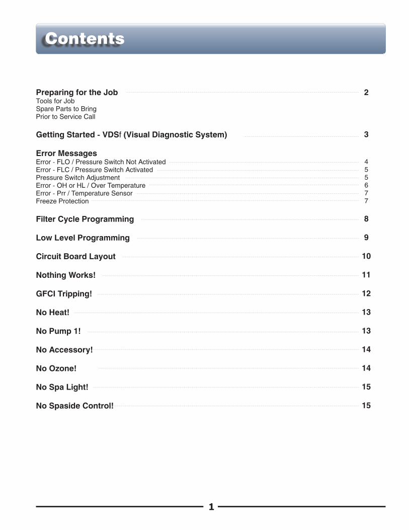
Preparing for the Job 2Tools for JobSpare Parts to BringPrior to Service Call
3Getting Started - VDSf (Visual Diagnostic System)
Error Messages4Error - FLO / Pressure Switch Not Activated5Error - FLC / Pressure Switch Activated5Pressure Switch Adjustment6Error - OH or HL / Over Temperature7Error - Prr / Temperature Sensor7Freeze Protection
8Filter Cycle Programming
9Low Level Programming
10Circuit Board Layout
11Nothing Works!
12GFCI Tripping!
13No Heat!
13No Pump 1!
14No Accessory!
14No Ozone!
15No Spa Light!
15No Spaside Control!
4
Contents

This Troubleshooting Manual has been designed for easy simple step-by-step problem solving and fault isolation.
It is important to identify all of the possible causes of the problem before making a final diagnosis. What you see at first is usually a symptom of the problem, not necessarily the problem itself.
Read the entire troubleshooting procedure related to what you are testing for prior to performing the test. This will give you a clearer overall view and help to avoid a mis-diagnosis.
Prepare for the service call. Make sure you have the right tools.
Tools for the Job:
! Multi-Meter and Clamp-On Ammeter! Jumper Cable! Accurate Thermometer! Standard & Philips Screwdrivers! 1/4 in. & 3/8 in. Open-End Wrench! 11/32 in. Nut Driver! GFCI Tester (optional)
Spare Parts to Bring:
! Spaside Control! Temperature Sensor! High-Limit Sensor! Fuses! Printed Circuit Board
Prior to the service call, have the homeowner check the following:
! Make sure spa has been filled to the water level suggested by the spa manufacturer.! Insure that all water shutoff valves are open and are not vibrating closed.! Adjust diverter valves and/or jets to allow adequate back pressure to heater assembly.! If “ FLO” appears on the spaside control display:! Have the homeowner remove the filter and operate system. If the error goes away, a filter
cleaning is required. The filter may not look dirty, we are dealing with oils, lotions etc... Use an appropriate filter-cleaning agent.
! Get data label information off of the spa control.
2
Preparing for the Job
3
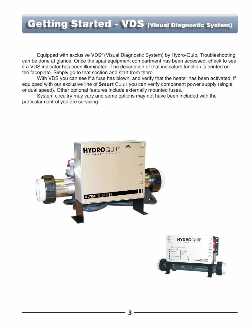
Equipped with exclusive VDSf (Visual Diagnostic System) by Hydro-Quip, Troubleshooting can be done at glance. Once the spas equipment compartment has been accessed, check to see if a VDS indicator has been illuminated. The description of that indicators function is printed on the faceplate. Simply go to that section and start from there.
With VDS you can see if a fuse has blown, and verify that the heater has been activated. If equipped with our exclusive line of Smart Cords you can verify component power supply (single or dual speed). Other optional features include externally mounted fuses.
System circuitry may vary and some options may not have been included with the particular control you are servicing.
Getting Started - VDS (Visual Diagnostic System)

With the pump(s) operating properly and “ FLO” showing on the spaside control you’ ve narrowed the problem down to the pressure switch. Perform the following tests to be sure that you have properly diagnosed the problem:
Note: There must be enough water in the spa for normal use. This error can also be caused be a restricted flow of water caused by debris caught in the plumbing. The heater will not activate while this error is displayed.
! Verify that the pump(s) is functioning properly. If the pump(s) is not functioning properly, refer to the Pump section that applies.
! Remove the filter and operate as normal. If the error clears, the filter is dirty and requires cleaning. Also check for air locks, closed valves or anything that would restrict the flow of water.
! Check the pressure switch cord connections at the system circuit board as well as at the pressure switch. Check for proper pin to connector alignment and security.
! If you’ ve verified that the pump(s) is functioning properly, the filter is not dirty, water shutoff valves are open, there is no debris in the plumbing causing a restricted flow of water and that all connections are secure, the pressure switch requires adjustment. Refer to page 5 for pressure switch adjustment.
Press Up/Down Arrow key to set temperature to the lowest setting (pump will shut off after 20-second cool down “ FLO” will clear indicating a problem exists while pump is running).
Pump is functioning properly (indicator solid in high speed, flashing in low speed).
Heater activated (indicator solid and heater indicator illuminated on faceplate).
4
FLO
HEATER “ ON” INDICATORTEMP. SET KEY
PUMP INDICATOR
FLO
Error - FLO

Error - FLC
FLC will only appear when the pump(s) is not operating. The error is also a protective feature and is an indication that the pressure switch in need of adjustment. Perform the following tests to be sure that you have properly diagnosed the problem:
Note: There must be enough water in the spa for normal use. The heater will not activate while this error is displayed.
! Disconnect the pressure switch cord at the printed circuit board, if the error does not go away replace the printed circuit board.
Pressure Switch Adjustment
1
2
3
PSI
Calibration Scale (1lb.)
Adjustment Screw
The function of the pressure switch is to turn the heater off if the pump stops operating or if there is restricted water flow (dirty filter, obstruction in the spa plumbing etc.).
The pressure switch has been preset at the factory to operate properly in normal conditions. Adjustment or other service may be required if you observe a flow related problem. If adjustment is required, follow the next steps carefully.
IMPORTANT: After any pressure switch adjustment, it is important to test the control by turning on the pump low speed and heater. While operating, unplug the pump, the heater must turn off. If the heater stays on, plug the pump back in and readjust the pressure switch to achieve proper operation.
1) With power to system turned OFF, remove the wires from the pressure switch terminals (secure wires safely to prevent any chance of electrical shock).
2) Turn power to the system ON. If system automatically starts in low speed, press Down Arrow key to set temperature to its lowest setting (pump will turn off after cool down cycle).
3) Place an Ohmmeter across the pressure switch terminals to verify an OPEN circuit.
4) Rotate the pressure switch adjustment screw counter-clockwise until the Ohmmeter indicates an CLOSED circuit.
5) Then rotate the pressure switch adjustment screw clockwise until the Ohmmeter indicates an OPEN circuit again.
6) Turn power to the system OFF and reconnect pressure switch terminals. Reapply power to the system and resume normal operation.
5
Error - FLC

If “ OH” or “ HL” appear in the spaside display window, an overheat condition has been detected. It is not safe to enter the spa until this error has been corrected.
If the water temperature exceeds 112BF at the systems temperature sensor (located in a plumbing dry-well or in wet-well in the spa) the system will shut off the heater “ OH” will appear in the lower spaside window and all other outputs will be disabled (pump(s), blower etc.) until the water temperature drops below 110BF.
If the water temperature exceeds 119BF at the systems high-limit sensor (clamped to the stainless steal heater assembly) “ HL” will appear in the lower spaside window and the system will shut off the heater only until the water temperature drops below 110BF. The pump(s), blower and other outputs will stay active.
! Carefully check the heater housing first to see if it is hot to the touch. If it is there may be an obstruction in the plumbing, a dirty filter or closed water shutoff valve. Power must be cycled off then back on for the system to reset this error.
! Check the water temperature with an accurate thermometer. If the temperature displayed on the spaside control greatly differs, the temperature sensor may not be fully inserted into the wet-well or may be defective. Inspect the sensor’ s circuit board connection (straighten and/or clean pins if needed). If this does not correct the problem, replace the sensor. (Remember to reset power to clear the error)
! It may be necessary to insulate around a temperature or high-limit sensor that is being adversely affected by the ambient (outside) temperature.
! If the weather is extremely hot, remove the spa cover. Running the blower may help cool the water. Add cold water if necessary. (Remember to reset power once the water has cooled)
! Lower the systems set temperature by pressing the Up/Down Arrow key, the “ Heater On” indicator should go out. If the indicator stays on, replace the system circuit board.
6
OH HL
Error - OH, HL
7
! If the “ Heater On” indicator did in fact go out, the pump may be overheating the spa. Lower the duration of the filter cycle as follows:
Press both the Light and Up Arrow keys, the current filter cycle duration will appear. Use the Down Arrow key to lower the duration of the filter cycle. Once the setting has been sufficiently lowered, press the Light and Up Arrow keys again to confirm the change. The display will then revert back to the standard Temperature display.
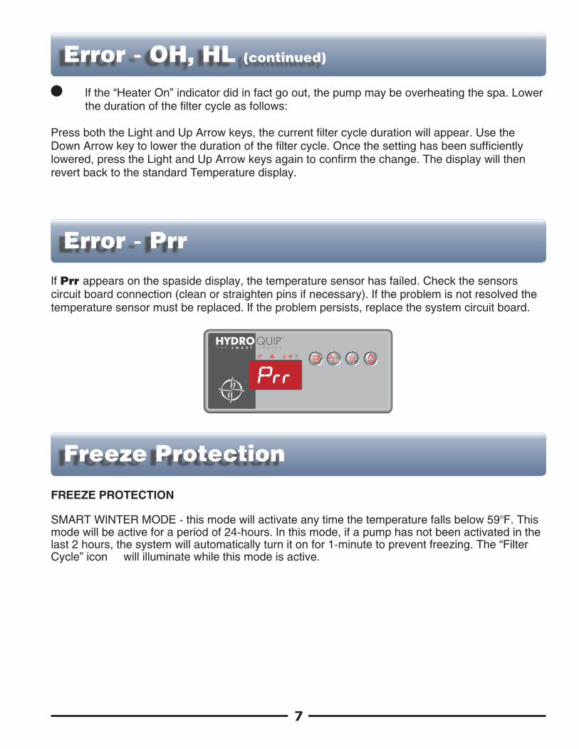
If Prr appears on the spaside display, the temperature sensor has failed. Check the sensors circuit board connection (clean or straighten pins if necessary). If the problem is not resolved the temperature sensor must be replaced. If the problem persists, replace the system circuit board.
Freeze Protection
FREEZE PROTECTION
SMART WINTER MODE - this mode will activate any time the temperature falls below 59BF. This mode will be active for a period of 24-hours. In this mode, if a pump has not been activated in the last 2 hours, the system will automatically turn it on for 1-minute to prevent freezing. The “ Filter Cycle” icon will illuminate while this mode is active.
Error - OH, HL (continued)
Error - Prr
P
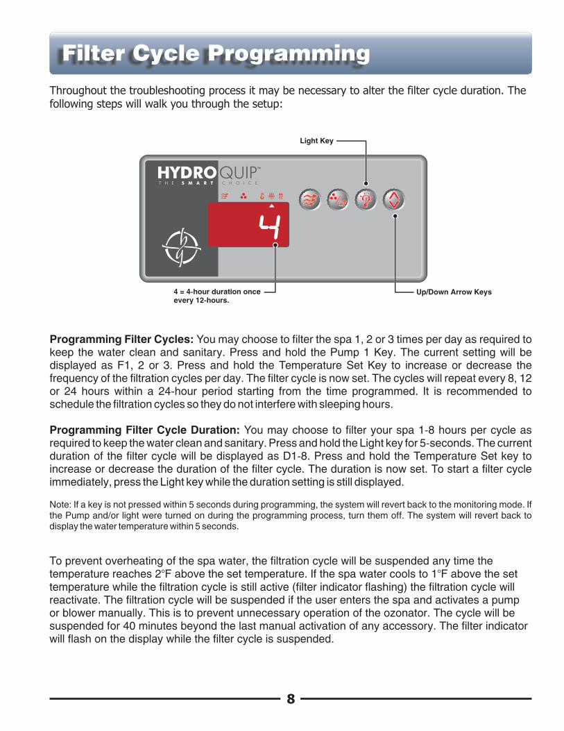
Throughout the troubleshooting process it may be necessary to alter the filter cycle duration. The following steps will walk you through the setup:
Programming Filter Cycles: You may choose to filter the spa 1, 2 or 3 times per day as required to keep the water clean and sanitary. Press and hold the Pump 1 Key. The current setting will be displayed as F1, 2 or 3. Press and hold the Temperature Set Key to increase or decrease the frequency of the filtration cycles per day. The filter cycle is now set. The cycles will repeat every 8, 12 or 24 hours within a 24-hour period starting from the time programmed. It is recommended to schedule the filtration cycles so they do not interfere with sleeping hours.
Programming Filter Cycle Duration: You may choose to filter your spa 1-8 hours per cycle as required to keep the water clean and sanitary. Press and hold the Light key for 5-seconds. The current duration of the filter cycle will be displayed as D1-8. Press and hold the Temperature Set key to increase or decrease the duration of the filter cycle. The duration is now set. To start a filter cycle immediately, press the Light key while the duration setting is still displayed.
Note: If a key is not pressed within 5 seconds during programming, the system will revert back to the monitoring mode. If the Pump and/or light were turned on during the programming process, turn them off. The system will revert back to display the water temperature within 5 seconds.
To prevent overheating of the spa water, the filtration cycle will be suspended any time the temperature reaches 2BF above the set temperature. If the spa water cools to 1BF above the set temperature while the filtration cycle is still active (filter indicator flashing) the filtration cycle will reactivate. The filtration cycle will be suspended if the user enters the spa and activates a pump or blower manually. This is to prevent unnecessary operation of the ozonator. The cycle will be suspended for 40 minutes beyond the last manual activation of any accessory. The filter indicator will flash on the display while the filter cycle is suspended.
8
4
Light Key
Up/Down Arrow Keys4 = 4-hour duration onceevery 12-hours.
Filter Cycle Programming

The Low Level settings such as Current Settings (limiting heater activation for low amperage systems), Single or Dual Speed Pump, Accessory (pump or blower) Configuration, Circulation Pump, Temperature Display (Fahrenheit or Celsius) and Light Configuration may be accessed directly from the spaside control.
9
Press and hold the Light Key for approximately 30 seconds, the first parameter will appear. Use the Up/Down Arrow Key to adjust the setting. Press the Light Key to cycle to the next parameter to be modified. The system will reset once the last parameter has been.
4
LIGHT KEY
Current Limiting:HC = High Current (No Current Limiting) *LC = Low Current (heater will turn off with high speed pump or accessory operation)
Pump 1 Configuration:SP 1 = Single Speed SP 2 = Dual Speed *
Accessory Configuration:BL 0 = Not InstalledBL 1 = Single Speed Pump 2 or Blower Installed *
Circulation Pump:CP 0 = No Circulation PumpCP 1 = Circulation Pump *
Temperature Display:Tu F = Fahrenheit *Tu C = Celsius
Light Configuration:LI 1 = Single Intensity (On/Off)LI 2 = Two Intensities *
* notes default setting
Low Level Programming
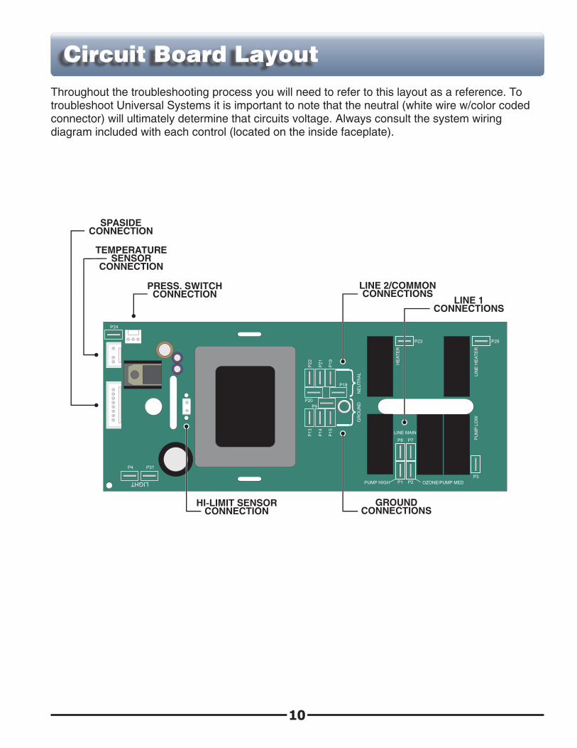
Throughout the troubleshooting process you will need to refer to this layout as a reference. To troubleshoot Universal Systems it is important to note that the neutral (white wire w/color coded connector) will ultimately determine that circuits voltage. Always consult the system wiring diagram included with each control (located on the inside faceplate).
10
P4 P31
LIGHT
P24
P2
2
P2
1
P1
9
P20
P18
P9
P1
3
P1
4
P1
5
NE
UT
RA
LG
RO
UN
D
P23 P29
HE
AT
ER
LIN
E H
EA
TE
R
LINE MAIN
P8 P7
P1 P2PUMP HIGH OZONE/PUMP MED
P3P
UM
P L
OW
LINE 2/COMMONCONNECTIONS
GROUNDCONNECTIONS
PRESS. SWITCHCONNECTION
HI-LIMIT SENSORCONNECTION
SPASIDECONNECTION
TEMPERATURESENSOR
CONNECTION
LINE 1CONNECTIONS
Circuit Board Layout
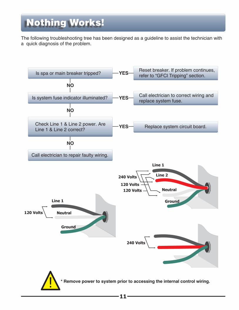
Is spa or main breaker tripped?
NO
Reset breaker. If problem continues, refer to “ GFCI Tripping” section.YES
Is system fuse indicator illuminated?YESCall electrician to correct wiring and replace system fuse.
NO
Check Line 1 & Line 2 power. Are Line 1 & Line 2 correct?
YESReplace system circuit board.
NO
Call electrician to repair faulty wiring.
The following troubleshooting tree has been designed as a guideline to assist the technician with a quick diagnosis of the problem.
* Remove power to system prior to accessing the internal control wiring.
11
240 Volts
120 Volts
Line 1
Neutral
Ground
240 Volts
Line 1
Line 2
Neutral
Ground
120 Volts
120 Volts
!
Nothing Works!
GFCI Tripping!
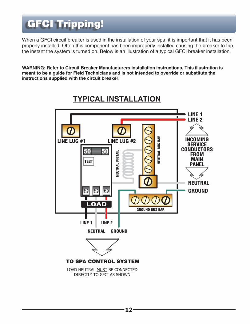
When a GFCI circuit breaker is used in the installation of your spa, it is important that it has been properly installed. Often this component has been improperly installed causing the breaker to trip the instant the system is turned on. Below is an illustration of a typical GFCI breaker installation.
WARNING: Refer to Circuit Breaker Manufacturers installation instructions. This illustration is meant to be a guide for Field Technicians and is not intended to override or substitute the instructions supplied with the circuit breaker.
GFCI
TEST
(Ground Fault Circuit Interrupter)
CIRCUIT BREAKER
NEU
TR
AL P
IGTAIL
NEU
TR
AL B
US B
AR
LINE 1
NEUTRAL
LINE 2
GROUND
GROUND BUS BAR
LINE LUG #1 LINE LUG #2
LINE 1LINE 2
INCOMINGSERVICE
CONDUCTORSFROMMAINPANEL
NEUTRAL
GROUND
TO SPA CONTROL SYSTEM
LOAD
LOAD NEUTRAL MUST BE CONNECTEDDIRECTLY TO GFCI AS SHOWN
12
TYPICAL INSTALLATION
YES
NO
YES
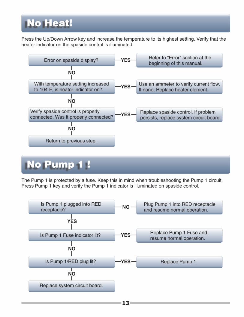
No Heat!
13
Error on spaside display?
NO
Refer to “ Error" section at the beginning of this manual.
YES
With temperature setting increased to 104BF, is heater indicator on?
YESUse an ammeter to verify current flow. If none, Replace heater element.
NO
Verify spaside control is properly connected. Was it properly connected? YESReplace spaside control. If problem
persists, replace system circuit board.
NO
Return to previous step.
Press the Up/Down Arrow key and increase the temperature to its highest setting. Verify that the heater indicator on the spaside control is illuminated.
No Pump 1 !
The Pump 1 is protected by a fuse. Keep this in mind when troubleshooting the Pump 1 circuit. Press Pump 1 key and verify the Pump 1 indicator is illuminated on spaside control.
Is Pump 1 plugged into RED receptacle?
YES
NOPlug Pump 1 into RED receptacle and resume normal operation.
Is Pump 1 Fuse indicator lit? Replace Pump 1 Fuse and resume normal operation.
NO
Replace system circuit board.
Is Pump 1/RED plug lit? Replace Pump 1
YES
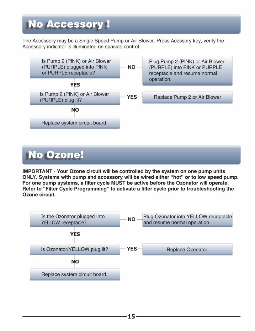
No Accessory !
The Accessory may be a Single Speed Pump or Air Blower. Press Acessory key, verify the Accessory indicator is illuminated on spaside control.
Is Pump 2 (PINK) or Air Blower (PURPLE) plugged into PINK or PURPLE receptacle?
YES
NOPlug Pump 2 (PINK) or Air Blower (PURPLE) into PINK or PURPLE receptacle and resume normal operation.
NO
Replace system circuit board.
Is Pump 2 (PINK) or Air Blower (PURPLE) plug lit? Replace Pump 2 or Air Blower
15
No Ozone!
YES
IMPORTANT - Your Ozone circuit will be controlled by the system on one pump units ONLY. Systems with pump and accessory will be wired either “ hot” or to low speed pump. For one pump systems, a filter cycle MUST be active before the Ozonator will operate. Refer to “ Filter Cycle Programming” to activate a filter cycle prior to troubleshooting the Ozone circuit.
Is the Ozonator plugged into YELLOW receptacle?
YES
NOPlug Ozonator into YELLOW receptacle and resume normal operation.
NO
Replace system circuit board.
Is Ozonator/YELLOW plug lit? Replace Ozonator
NO
YES
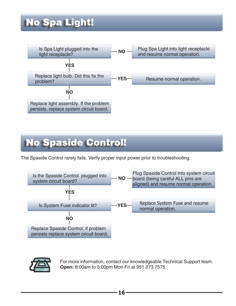
No Spa Light!
Is Spa Light plugged into the light receptacle?
YES
NOPlug Spa Light into light receptacle and resume normal operation.
Replace light bulb. Did this fix the problem? Resume normal operation.
Replace light assembly. If the problem persists, replace system circuit board.
16
No Spaside Control!
NO
YES
The Spaside Control rarely fails. Verify proper input power prior to troubleshooting.
Is the Spaside Control plugged into system circuit board?
YES
NOPlug Spaside Control into system circuit board (being careful ALL pins are aligned) and resume normal operation.
Is System Fuse indicator lit? Replace System Fuse and resume normal operation.
Replace Spaside Control, if problem persists replace system circuit board.
For more information, contact our knowledgeable Technical Support team.Open: 8:00am to 5:00pm Mon-Fri at 951.273.7575

85-0150-C Rev.1 12.06