Embed Size (px)
Citation preview

The Anthracite Chapter
NEWS March 2016
ASHRAE - Shaping Tomorrow’s Built Environment Today
2015-2016 OFFICERS & CHAIRS President: Rich Karns [email protected] (570) 287-3161 x210 President-Elect: Alyssa Procida [email protected] (570) 821-4923 Vice-President Eric Turner [email protected] Treasurer: Jon Keller [email protected] (570) 342-7778 Secretary & Research Promotion Chair: Maxwell Tamasy [email protected] (724) 797-4908 Board of Governors: Dan Mello: (570) 288-8759 Board of Governors & Student Activities Chair: Tracey Jumper [email protected] (570) 471-3480 Board of Governors & Chapter Technology Transfer Chair: Matt Archey, PE [email protected] (570) 821-1994 x1257 Grassroots Government Activities Chair: A.J. Speicher, PE [email protected] (570) 821-1994 x 303 Historian & Newsletter Editor: Walt Janus, PE [email protected] (570) 342-3700 x5915 Membership Promotion Chair: Gary Booth [email protected] (570) 814-0042 Research Promotion Co-Chair: Cory Lock [email protected] (215) 348-1497 Website Homepage Editor: Karl Grasso [email protected] (570) 562-2778 Young Engineers in ASHRAE Chair: Walt Stout [email protected] (570) 821-1994 x1512
President’s Message This month we are pleased to welcome our colleagues from SMACNA. SMACNA (Sheet Metal and Air Conditioning Contractors National Association) writes the guidelines that are the widely accepted standard for sheet metal and related accessory fabrication and installation. Pick up any mechanical specification and you will see the SMACNA “HVAC Duct Construction Standards – Metal and Flexible” referenced as the standard to which the metal duct systems must comply. SMACNA also offers many publications referencing specific production and installation guidelines, such as seismic restraint systems, duct system testing and fire/smoke damper selection and installation. Our topic for this month is an important review of “Through- Penetration Firestopping”. It cannot be stressed enough that we in the HVAC industry must keep current with the proper selection and application of the many products and assemblies designed to ensure that building occupants are safe in a fire or smoke situation. Speaking from experience, I have seen many misapplications in the field, some of which were picked up by the Authority Having Jurisdiction (AHJ) and some were not. We must review firestopping on a regular basis as designers and installers of this critical life safety process. As mentioned in last month’s issue of The Anthracite Chapter NEWS, this is the month at which your President announces the names of the candidates who will be vying for Chapter Officer positions. We will also be taking nominations from the floor of members who may have an interest in serving as an officer in our Chapter. The final election will be held by ballots sent to the members through Survey Monkey at the end of March. Please participate in the election. We have a strong Chapter, and the election of qualified candidates will guarantee that we will remain a strong Chapter. Once again, it is not too late to throw your name in the hat by contacting our Chapter Secretary, Max Tamasy, or any of the other board members. We would love to have you join us. Continued on page 3
Chapter Website: http://anthracite.ashraechapters.org

ASHRAE ANTHRACITE CHAPTER MEETING
Tuesday March 15, 2016
Through-Penetration Firestop Systems
Presented by
Richard N. Walke
Rich is a Senior Regulatory Engineer with Underwriters Laboratories (UL) in Northbrook, IL. His responsibilities include providing fire protection related technical support to the regulatory community, providing educational seminars, developing internet based training programs, interacting on code change activities and serving as a liaison between the UL engineering staff and the regulatory community. Prior to this assignment, Rich was actively engaged in fire protection engineering for 29 years. He provided the supervisory and review activities of engineering investigations conducted on fire resistive construction, through-penetration firestop systems, joint systems, perimeter fire containment systems, fire resistive electrical outlet boxes, electrical circuit protections systems, fire resistive grease and air ducts systems, interior finish building materials, air duct materials and solid fuel heating appliances. Rich recently had the honor of serving on the Fire Safety Committee at the ICC Committee Action Hearings in Memphis. He is also a member of the NFPA 101/5000 Fire Protection Features and NFPA 220/221 Building Construction Committees. Rich received a Bachelor of Science Degree in Civil Engineering from Valparaiso University in 1976. He is currently a Certified Quality Engineer with the American Society for Quality Control. Rich will discuss ductwork and piping firestop assembly selection and construction and where to look in the UL database to select an approved firestop system.
A Certificate of Attendance will be available at the registration table Location: Cooper’s Seafood Waterfront
304 Kennedy Blvd, Pittston, PA 18640 (570) 654-6883
Schedule: 5:00-5:45 p.m. Business Meeting (All are Welcome) 5:30-6:30 p.m. Social Hour (Cash Bar) 6:00-6:30 p.m. Program Registration 6:30-7:15 p.m. Dinner (Buffet) 7:15-8:30 p.m. Technical Presentation Cost: $ 30.00 per person FREE for Students (ASHRAE Members are encouraged to sponsor Students)
Only If You Are Planning to Attend Please Respond by NOON on FRIDAY March 11, 2016 to Walt Janus at (570) 342-3700 Ext. 286 or via e-mail at [email protected]

NEWS and Notes President’s Message, Continued Finally, once again I am asking for our loyal members to invite coworkers from you firms to attend this meeting, as well as future meetings. It is a great way to meet the people that you are associated with one way or another in the HVAC field and hopefully they may even learn something valuable. When you bring these new faces to our meetings, please introduce them to me and our board members. We are always excited to meet them. See you at the meeting.
Rich Karns ASHRAE Webinar Planned
ASHRAE’s upcoming webcast will broadcast live on April 21 from 1:00 to 4:00 pm EDT. This FREE webcast is brought to you by the Chapter Technology Transfer Committee. “The presenters will discuss the primary technical and financial challenges in achieving net zero buildings,” said Nathan Hart, chair of the CTTC Webcast Ad Hoc Committee. “Viewers will learn the importance of, and why we should strive for, net zero in the built environment. The focus will be on realistic solutions and methods of energy conservation.” Online registration for the webcast will begin on March 21. For more information on the webcast program, sponsorship opportunities, continuing education credits, and ASHRAE resources related to net zero, visit www.ashrae.org/webcast. Also the Chapter Board is considering hosting the webcast at a central location to be announced. Watch for more details either by e-mail or in the April issue of the NEWS. Technology Corner The reprint article “Selecting Air Distribution Outlets Designing for Comfort” is included at the end of this month’s edition of the NEWS, and is courtesy of the ASHRAE Journal. You may submit articles for consideration to be included in future editions to CTTC chair Matt Archey.

Thanks to Our Sponsors
The display of business cards in the NEWS recognizes the financial support of the Chapter by the individual or business and does not constitute an endorsement or recommendation by ASHRAE or the Anthracite Chapter.

Thanks to Our Sponsors
The display of business cards in the NEWS recognizes the financial support of the Chapter by the individual or business and does not constitute an endorsement or recommendation by ASHRAE or the Anthracite Chapter.

Thanks to Our Sponsors
The display of business cards in the NEWS recognizes the financial support of the Chapter by the individual or business and does not constitute an endorsement or recommendation by ASHRAE or the Anthracite Chapter.
ANTHRACITE CHAPTER NEWS Walt Janus, Editor c/o Greenman-Pedersen, Inc. 50 Glenmaura National Blvd, Suite 102 Scranton, PA 18505
ASHRAE MISSION
• To advance the arts and sciences of heating, ventilating, air conditioning and
refrigerating to serve humanity and promote a sustainable world.
ASHRAE VISION
• ASHRAE will be the global leader, the foremost source of technical and educational
information, and the primary provider of opportunity for professional growth in the arts
and sciences of heating, ventilating, air conditioning and refrigerating.
2014-15 Matt Archey 2005-06 Manish Patel 1996-97 Charlie Smith 1987-88 Ray Suhocki 2013-14 Matt Archey 2004-05 A.J. Lello 1995-96 Chuck Swinderman 1986-87 Jerry Peznowski 2012-13 Tracey Jumper 2003-04 Dennis Gochoel 1994-95 John Walker 1985-86 Lee Garing 2011-12 A.J. Speicher 2002-03 Phil Latinski 1993-94 Dennis McGraw 1984-85 Spence Martin 2010-11 Tom Swartwood 2001-02 Mike Moran 1992-93 Scott Harford 1983-84 Donald Brandt 2009-10 Brian Flynn 2000-01 Dennis Gochoel 1991-92 Dan Mello 1982-83 Rich Santee 2008-09 Eric Zanolini 1999-00 John Durdan 1990-91 Mark Hagen 1981-82 Bob Mugford 2007-08 Walt Janus 1998-99 Matthew Martin 1989-90 Paul Dreater 1980-81 Kerry Freeman 2006-07 John Havenstrite 1997-98 Dean Butler 1988-89 Bud Reilly
Ant
hrac
ite C
hapt
er
Pas
t-Pre
side
nts
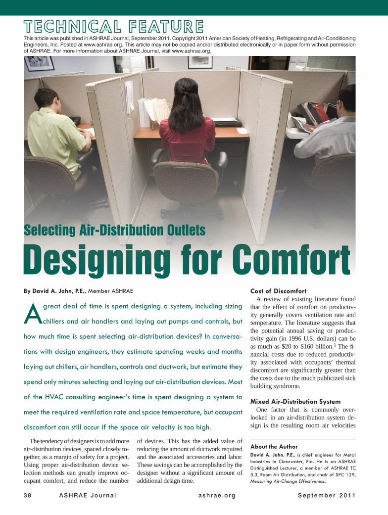
ANTHRACITE CHAPTER 2015-2016 MEETINGS & EVENTS
Date Theme Program Speaker
Sept. 15 Membership/Bring-a-Buddy
Joint Meeting with AIA
Geisinger Clinic Tour / Building Performance Analysis for Building Performance Rating Tools
M. Dennis Knight*
Oct. 20 Research Promotion –
Donor Recognition
Heating Applications with Variable Refrigerant Flow (VRF) Technology
Phil Latinski
Nov. 17 Students/YEA Building Information Modeling (BIM) Michael Brown
December Family Night No Meeting --
Jan. 19 Research Promotion Hybrid Heating Plant Design Luke Wonnell
Feb. 16 Engineer’s Week
Joint Meeting with PSPE
Basic Electricity Theory and Safety for Non-EEs
Mark Rutkowski
Mar. 15 Nominating Night
Joint Meeting w/SMACNA
Through-Penetration Firestop Systems Richard Walke
April 19 Students/Membership DDC Control Strategies A.J. Speicher
April 21 ASHRAE Webinar Making Net Zero Net Positive:
Solving the Efficiency & Cost Paradox Panel
May 17 Past-Presidents
Joint Meeting with ASHE Infection Control in HVAC Systems Bill Bahnfleth**
TBA Research Promotion Car Show --
June 21 Fun & Fellowship Mark A. Hagan, PE Memorial Golf Tournament --
Aug. 18-20 Chapters Regional Conf. 2016 Region III CRC - Philadelphia, PA --
*ASHRAE Fellow and Distinguished Lecturer **ASHRAE Presidential Member and Distinguished Lecturer

ASHRAE Learning Institute
2016 Spring Online Course Series
HVAC Design: Level I – Essentials - Registration is $1,264 ($1,009 ASHRAE Member)
Gain practical skills and knowledge in designing and maintaining HVAC systems that can be put to immediate use. The training provides real-world examples of HVAC systems, including calculations of heating and cooling loads, ventilation and diffuser selection using the newly renovated ASHRAE Headquarters building as a living lab.
HVAC Design: Level II – Applications - Registration is $854 ($699 ASHRAE Member)
HVAC Design: Level II — Applications provides instruction on HVAC system design for experienced HVAC designers and those who complete the HVAC Design: Level I – Essentials training. The training provides information that allows practicing engineers and designers an opportunity to expand their exposure to HVAC systems design procedures for a better understanding of system options to save energy.
Visit www.ashrae.org/hvactraining to register.
ASHRAE HVAC Design Training 2 Courses, 5 Days of Intense Instruction
Atlanta ● Cleveland ● Halifax ● Hong Kong ● Kuala Lumpur
Miami ● Minneapolis ● San Francisco ● Vancouver
2 WAYS TO REGISTER Take 3 or more courses and save 15% off registration! Internet: www.ashrae.org/onlinecourses Phone: Call toll-free at 1-800-527-4723 (US and Canada) or 404-636-8400 (worldwide) Price: $284 ($219 ASHRAE Member); Two-part courses: $484 ($359 ASHRAE Member)
Note: You may register up to 24 hours prior to an online course. Courses are in US Eastern Time.
Combined Heat & Power: Creating Efficiency through Design & Operations Mon, March 28, 2016 – 1:00 pm to 4:00 pm EDT Commissioning Process & Standard 202 Wed, March 30, 2016 – 1:00 pm to 4:00 pm, EDT IT Equipment Design Evolution & Data Center Operation Optimization Wed, April 6, 2016 – 1:00 pm to 4:00 pm, EDT Complying with Standard 90.1-2013: HVAC/Mechanical Wed, April 13, 2016 – 1:00 pm to 4:00 pm, EDT Laboratory Design: The Basics and Beyond Mon, April 18, 2016 – 1:00 pm to 4:00 pm, EDT
Standard 188-2015 – Successfully Managing the Risk of Legionellosis Mon, April 25, 2016 – 1:00 pm to 4:00 pm, EDT
Air-to-Air Energy Recovery Applications: Best Practices Wed, April 27, 2016 – 1:00 pm to 4:00 pm, EDT Fundamental Requirements of Standard 62.1-2013 Mon, May 2, 2016 – 1:00 pm to 4:00 pm, EDT
Variable Refrigerant Flow System Design & Applications Mon, May 16, 2016 – 1:00 pm to 4:00 pm, EST The following courses are comprised of two parts. Registrants must attend both parts in order to receive CEU/PDH credits.
Exceeding Standard 90.1-2013 to Meet LEED® Requirements Part 1: Mon, April 11, 2016 – 1:00 pm to 4:00 pm, EDT Part 2: Wed, April 20, 2016 – 1:00 pm to 4:00 pm, EDT
Operations & Maintenance of High-Performance Buildings Part 1: Tue, May 17, 2016 – 1:00 pm to 4:00 pm, EDT Part 2: Wed, May 18, 2016 – 1:00 pm to 4:00 pm, EDT
38 AS HRAE Jou rna l ash rae .o rg S e p t e m b e r 2 0 1 1
A great deal of time is spent designing a system, including sizing
chillers and air handlers and laying out pumps and controls, but
how much time is spent selecting air-distribution devices? In conversa-
tions with design engineers, they estimate spending weeks and months
laying out chillers, air handlers, controls and ductwork, but estimate they
spend only minutes selecting and laying out air-distribution devices. Most
of the HVAC consulting engineer’s time is spent designing a system to
meet the required ventilation rate and space temperature, but occupant
discomfort can still occur if the space air velocity is too high.
The tendency of designers is to add more air-distribution devices, spaced closely to-gether, as a margin of safety for a project. Using proper air-distribution device se-lection methods can greatly improve oc-cupant comfort, and reduce the number
of devices. This has the added value of reducing the amount of ductwork required and the associated accessories and labor. These savings can be accomplished by the designer without a significant amount of additional design time.
Cost of DiscomfortA review of existing literature found
that the effect of comfort on productiv-ity generally covers ventilation rate and temperature. The literature suggests that the potential annual saving or produc-tivity gain (in 1996 U.S. dollars) can be as much as $20 to $160 billion.1 The fi-nancial costs due to reduced productiv-ity associated with occupants’ thermal discomfort are significantly greater than the costs due to the much publicized sick building syndrome.
Mixed Air-Distribution SystemOne factor that is commonly over-
looked in an air-distribution system de-sign is the resulting room air velocities
About the AuthorDavid A. John, P.E., is chief engineer for Metal Industries in Clearwater, Fla. He is an ASHRAE Distinguished Lecturer, a member of ASHRAE TC 5.3, Room Air Distribution, and chair of SPC 129, Measuring Air-Change Effectiveness.
By David A. John, P.E., Member ASHRAE
Designing for Comfort Selecting Air-Distribution Outlets
This article was published in ASHRAE Journal, September 2011. Copyright 2011 American Society of Heating, Refrigerating and Air-Conditioning Engineers, Inc. Posted at www.ashrae.org. This article may not be copied and/or distributed electronically or in paper form without permission of ASHRAE. For more information about ASHRAE Journal, visit www.ashrae.org.

Sep tember 2011 ASHRAE Jou rna l 39
generated by the outlets and the spacing of the outlets. It is fairly common to see outlets spaced too close together and the down-ward draft that is generated. Also, it is common to see outlets placed too close to an architectural feature that protrudes below the ceiling, resulting in the horizontal jet being forced down into the space and causing drafts for the occupants.
Several methods described below can be used to avoid high velocity jets and the resulting drafts when selecting outlets for an air-distribution system. These methods can be imple-mented without adding a significant amount of design time for a project. Designing to control room air motion will lead to higher levels of comfort and a more productive environment.
Defining a Fully Mixed SystemASHRAE Handbook—Fundamentals, Chapter 20, Space
Air Diffusion, defines a fully mixed system as the following: “In mixed-air systems, high-velocity supply jets from air
outlets maintain comfort by mixing room air with supply air. This air mixing, heat transfer and resultant velocity reduction should occur outside the occupied zone. Occupant comfort is maintained not directly by motion of air from the outlets, but from secondary air motion that results from mixing in the un-occupied zone. Comfort is maximized when uniform tempera-ture distribution and room air velocities of less than 50 fpm (0.25 m/s) are maintained in the occupied zone.”
A fully mixed system ideally maintains a constant temper-ature gradient from the floor to the top of the occupied zone. Unlike displacement systems or underfloor systems, the fully mixed system maintains a uniform temperature through di-lution of the space air with the air supplied into the space (Figure 1).
Typically, a forced air system is designed to meet the fol-lowing performance parameters: 73°F to 77°F (23°C to 25°C) with humidity at 25% to 60% and air velocity in the occupied zone of less than 50 fpm (0.25 m/s).
Figure 1: Classification of air-distribution strategies (from 2009 ASHRAE Handbook—Fundamentals).
The latest version of ASHRAE Standard 55-2010 allows for elevated air speeds “to be used to increase the maximum oper-ative temperature for acceptability under certain conditions.” These temperatures and velocities are shown in the standard’s Figure 5.2.3.1. This article covers air outlet selection where the desired temperature range is 73°F to 77°F (23°C to 25°C).
Effect of Velocity on ComfortFigure 2 shows the effect of room air velocity on the perception
of comfort. The figure also shows the neck region is more sensi-tive to air motion then the ankle region. As you can see from the graph, in the neck region, the percentage of complaints are signif-icant at and above 50 fpm (0.25 m/s) velocity. In many cases, the perception of a draft is not because of air temperature, but rather the velocity of air around the occupants. This can be demonstrat-ed by the use of a ceiling fan that is turned on to provide cooling, even though the air being circulated is at room temperature.
Outlet SelectionWhen designing a fully mixed system for comfort, it is
important to define the occupied and unoccupied zone for a space. The occupied zone is the space we live and work in. It is typically the volume from the floor up to a height of 6 ft (1.8 m) and 6 in. to 1 ft (152 mm to 305 mm) from the walls. The occupied zone depends on the specific space and use of that space. We can use the unoccupied zone to deliver all the high velocity supply air and do all the mixing.
The tool that can be used by a designer to predict the location of a discharge jet is listed as “throw” in a manufacturer’s catalog. The current standard for outlet testing is ASHRAE Standard 70-2006 (RA 2011), Method of Testing the Performance of Air Outlets and Air Inlets, which defines how throw data is obtained and allows the testing of both isothermal and non-isothermal air. Most of the manufacturer’s throw data is, in fact, isothermal air. The reason for this is the data is easier to obtain and is re-

40 AS HRAE Jou rna l ash rae .o rg S e p t e m b e r 2 0 1 1
peatable. Non-isothermal air requires a balanced room, which does require a significant amount of time to conduct testing.
Discharge JetsOutlets generate a discharge jet. The designer should se-
lect the type of outlet and space the outlets so that the maxi-mum velocity in the occupied space does not exceed 50 fpm (0.25 m/s). There are several principles of jet behavior that if used along with the manufacturer’s catalog throw data, the designer can better predict the resulting velocities in the oc-cupied zone.
These principles include: • A free jet expands at approximately 22°. The expansion of
the jet is due to the induction of air around the jet. • If a jet is directed toward a surface, the jet will want to stay
on that surface regardless if the surface is a ceiling, wall or floor. • At some point, a cooled jet projected along a horizontal
ceiling service will separate from the surface and drop down-wards. The point where the jet leaves the ceiling is defined as the separation point.
In a mixed air system, the outlet is an “engine” that produces a discharge jet into the unoccupied zone causing air in the oc-cupied zone to be induced into the supply jet. A typical diffuser induces 20 to 30 times the amount of supply air discharged. This rate of induction is how we maintain comfort in a mixed air system. By discharging jets of air into the unoccupied zone, we create air motion and circulation in the occupied zone.
Because of the high rate of induction generated by outlets, the temperature of the supply jet reaches near space tempera-ture within a very short distance from the outlet. Most of the exchange of load from the supply air to the room air occurs within several feet from the outlet.
The outlets should be spaced to ensure that the entire occu-pied zone has some induction and air motion to avoid stagnant
areas. Placing returns in stagnant areas will not create air mo-tion to pull room air to the return.
Selection by Noise CriteriaThe most common method of outlet selection is by using
noise criteria (NC) for a device at the required cfm. The de-signer determines the outlet type and size by using the required cfm for an outlet and the maximum NC levels desired for a space. The NC targeted values most commonly used are from Table 1 of the 2011 ASHRAE Handbook—HVAC Applications, Chapter 48, Noise and Vibration Control (examples of recom-mended NC values from the Handbook are shown in Table 1) .
Although this method will select devices that meet required sound levels, it does not address the primary requirements of maximizing thermal comfort in the occupied zone. Using this method, the diffusers can be spaced too close together creating a draft with a velocity of more than 50 fpm (0.25 m/s) in the oc-cupied zone. This method can also lead to stagnant zones where there is little or no induction from the space into the supply outlet.
Selection Using Throw DataUsing the published throw data obtained from a manufac-
turer’s catalog is one method of outlet selection that can be used to predict room air velocity. This information will in-dicate the performance of the discharge jet once it leaves the outlet and can be used to fairly accurately predict resulting space velocities (Figures 3a and 3b).
Throw data obtained per ASHRAE Standard 70-2006 is typi-cally given in a manufacturer’s catalog at 50, 100 and 150 fpm (0.25, 0.51 and 0.76 m/s) (Figure 4). Throw is defined as the distance, in ft (m), from the center of the outlet perpendicular to a point in the mixed airstream where the velocity has been reduced to a specified terminal velocity. In most cases, throw data is based on isothermal air. If either cooled or heated air is
Figure 2: Difference in perception of drafts between the ankle (left) and neck (right) region and percentage of occupants object-ing to drafts in air-conditioned rooms (from 2009 ASHRAE Handbook—Fundamentals). Temperature difference is between local temperature and average room temperature.
Air
Vel
oci
ty (
fpm
)
Temperature Difference (°F)
Air
Vel
oci
ty (
fpm
)
Temperature Difference (°F)
Ankle Region Neck Region

42 AS HRAE Jou rna l ash rae .o rg S e p t e m b e r 2 0 1 1
100 fpm Isovel
50 fpm
150 fpm
Throw
Diffuser Under Test
Figure 4: Plan view of ceiling-mounted outlet indicating location of 150, 100 and 50 fpm isovels (from ASHRAE Standard 70-2006).
Figure 3a (top): Airstream drop distance. Figure 3b (bottom): Airstream spread (from ASHRAE Standard 70-2006 (RA 2011), Method of Testing the Performance of Air Outlets and Air).
Drop
Drop
Ceiling May or May Not Be Present
Spread
Side View
Top View
shown, the throw data does not indicate the drop or rise of the jet or the spread of the jet. Using the throw information, a designer can map out the location of outlets so as to predict and maintain velocity in the occupied zone below 50 fpm (0.25 m/s).
Selection by T50/L and ADPIAnother available method to predict air velocities and comfort
in the occupied zone is by using the T50 /L ratio to predict the re-sulting ADPI value for a space where T50 is the cataloged throw data to 50 fpm and L is the characteristic length of the space being evaluated. Characteristic Length L is the horizontal distant from the outlet to the outside of the zone the outlet serves. If the outlet is placed so that there are differing distances from the outlet out to the zones served (i.e. a four way pattern), the outlet may have up to four different L values that are used to calculate the T50/L ratio in each direction. Characteristic Length L is defined in Table 3 in Chapter 57 of the 2011 ASHRAE Handbook—HVAC Applications.
What is ADPIAir diffusion performance index (ADPI) is a single number
that quantifies the overall comfort of a space when in cooling. ADPI is the percentage of points in a space where the effective draft temperature is between –3°F and +2°F (–19°C and –17°C) and the air velocity is less than 70 fpm (0.36 m/s). A high per-centage of people have been found to be comfortable in cooling applications for office-type occupations where these conditions are met. High ADPI values generally correlate to high space ther-mal comfort levels with the maximum obtainable value of 100.
The effective draft temperature provides a quantifiable indication of comfort at a discrete point in a space by combining the physi-ological effects of air temperature and air motion on a human body.
A point is considered comfortable if the results of Equa-tion 1 are between –3°F and +2°F (–19°C and –17°C), and the measured velocity at the point is less than 70 fpm (0.36 m/s).
Ted = (Tx – Tc) – 0.07(Vx – 30) (1)where
Ted = effective draft temperature, °FTx = local airstream dry-bulb temperature, °F
Table 1: Examples of recommended NC values (from 2011 ASHRAE Handbook—HVAC Applications).
Room Types NC/RC dBA dBC
Rooms with Intrusion from Outdoor Noise SourcesTraffic Noise N/A 45 70
Aircraft Flyovers N/A 45 70
Residences, Apartments, CondominiumsLiving Areas 30 35 60
Bathrooms, Kitchens, Utility Rooms 35 40 60
Hotels/Motels
Individual Rooms or Suites 30 35 60
Meeting/Banquet Rooms 30 35 60
Corridors and Lobbies 40 45 65
Service/Support Areas 40 45 65
Office Buildings
Executive and Private Offices 30 35 60
Conference Rooms 30 35 60
Teleconference Rooms 25 30 55
Open-Plan Offices 40 45 65
Corridors and Lobbies 40 45 65

44 AS HRAE Jou rna l ash rae .o rg S e p t e m b e r 2 0 1 1
High Velocities in Occupied Zone A system can be designed with proper
capacities and air changes but still result in discomfort due to air greater than 50 fpm (0.25 m/s) entering the occupied zone. Designing to avoid the air-distribution problems shown in Figures 5 and 6 will greatly improve the comfort of a space.
Tc = average (control) room dry-bulb temperature, °F
Vx = local airstream centerline ve-locity, fpm
By determining the value of T50 from a manufacturer’s catalog, and measuring the characteristic length L from the proj-ect’s plans, the ratio can be determined and the predicted ADPI value can be es-timated from Table 2.
Location of Return/Exhaust GrillesASHRAE Handbook—HVAC Applica-
tions, Chapter 57, Room Air Distribu-tion, recommends that “A return inlet affects room air motion only in its im-mediate vicinity. The intake should be located in the stagnant zone to return the warmest room air during cooling or the coolest room air during heating. The im-portance of the location depends on the relative size of the stagnant zone, which depends on the type of outlet.”
Also, the return or exhaust grille does not short circuit the supply jet. In fact, if a supply jet is at or above 150 fpm (0.76 m/s) and directed over a return, the jet will either pull air out to the re-turn or exhaust or create a “blanking effect” over the return or exhaust where no air is taken out of the space. If the return or exhaust is placed at the end of the supply jet where the velocity is 150 fpm (0.76 m/s) or less, the air being re-turned is at or near room temperature and the amount of air being returned is close to 5% of the total air motion in the space.
Figure 5 (left): Colliding airstreams can project a high velocity airstream into the occupied zone. This can be predicted by map-ping the catalog throw data or the T50/L ratio. Figure 6 (right): Obstructions in the airstream such as architectural details and support beams can force the supply jet down into the occupied zone causing occupant discomfort.
Horizontal Throw
Vertical Throw
Colliding Airstream Throw Distance of Jet = Horizontal + Vertical
Horizontal Throw
Vertical Throw
Obstruction in Path of Discharge Jet Throw Distance of Jet = Horizontal + Vertical
Terminal Device
Room Load, Btu/h·ft2
T50/L for Maximum ADPI
Maximum ADPI
For ADPI Greater Than
Range of T50/L
High Sidewall Grilles
80 1.8 68 – –60 1.8 72 70 1.5 to 2.240 1.6 78 70 1.2 to 2.320 1.5 85 80 1.0 to 1.9
<10 1.4 90 80 0.7 to 2.1
Circular Ceiling Diffusers
80 0.8 76 70 0.7 to 1.360 0.8 83 80 0.7 to 1.240 0.8 88 80 0.5 to 1.520 0.8 93 90 0.7 to 1.3
Sill Grille, Straight Vanes
80 1.7 61 60 1.5 to 1.760 1.7 72 70 1.4 to 1.740 1.3 86 80 1.2 to 1.820 0.9 95 90 0.8 to 1.3
Sill Grille, Spread Vanes
80 0.7 94 90 0.6 to 1.560 0.7 94 80 0.6 to 1.740 0.7 94 – –20 0.7 94 – –
Ceiling Slot Diffusers
(For T100/L)
80 0.3 85 80 0.3 to 0.760 0.3 88 80 0.3 to 0.840 0.3 91 80 0.3 to 1.120 0.3 92 80 0.3 to 1.5
Light Troffer Diffusers
60 2.5 86 80 <3.840 1.0 92 90 <3.020 1.0 95 90 <4.5
Perforated, louvered ceiling
diffusers
11 to 50 2.0 96 90 1.4 to 2.7
80 1.0 to 3.4
Table 2: Air diffusion performance index (ADPI) selection guide (from Table 4, Chap-ter 57 of the 2011 ASHRAE Handbook—Applications).
Examples Using Throw DataThe following examples show how
the throw data can be used to predict the resulting air motion in a space. In this example, the space is 20 ft × 20 ft with 9 ft (6 m × 6 m with 3 m) ceil-ings and the required airflow is 950 cfm (448 L/s).

46 AS HRAE Jou rna l S e p t e m b e r 2 0 1 1
9 ft
5 ft 5 ft10 ft
4 ft 4 ft
Figure 7 (left): Diffuser Performance. Two louver-faced 15 in. × 15 in. (381 mm × 381 mm) inlets. Each diffuser is 469 cfm (1650 L/s), totaling 938 cfm. Throw data is 18 (50 fpm) and NC<20. Use the T50/L ratio to obtain ADPI range for 90%: 1.4 to 2.7 and T50/L calculation 18/5 = 3.6. Figure 8 (right): Diffuser Performance. One louver-faced 21 in. × 21 in. inlets with four-way dis-charge. Each diffuser is 919 cfm. Throw data is 24 (50 fpm) and NC<20. Use the T50/L ratio to obtain ADPI range for 90%: 1.4 to 2.7 and T50/L calculation 24/10 = 2.4.
9 ft
10 ft
5 ft 5 ft
10 ft
Example 1In this example (Figure 7), colliding airstreams will generate a high velocity in the occupied zone. The T50 /L calculation shows a value of 3.6, higher than the desired 1.4 to 2.7, indicating a draft in the occupied zone. We also can predict too high a veloc-
ity in the center of the space by mapping out the throws of the outlets.
Example 2To reduce the room air velocity, one diffuser is selected and placed in the center of the room (Figure 8). The value of T50 /L is now 2.4 and within the recommend range to maxi-mize the ADPI value for the space. Although the supply jet does reach the floor and enters the occupied zone, from Fig-ure 2 we know that the ankle region is much more tolerant to higher velocities compared to the neck region.
This selection has eliminated one diffuser compared to Example 1 and the associated costs while providing a higher level of comfort.
ConclusionMost HVAC designers spend a significant amount of time
selecting chillers, air handlers, pumps and cooling towers with the purpose of maintaining occupant thermal comfort in a space. Most conventional air distribution systems in North America are mixed air systems where space comfort is main-tained through the induction of air from the occupied zone into the unoccupied zone. The definition of comfort includes maintaining room air velocities below 40 fpm to 50 fpm (0.20 m/s to 0.25 m/s). This is sometimes overlooked by designers, resulting in discomfort to the space occupants caused by ex-cessive air motion.
By using some simple selection techniques such as mapping cataloged throw data and the T50 /L method to predict ADPI, designers can select and space outlets to maximize the com-fort level in an occupied space. Using these methods also of-fers the opportunity to reduce the required number of outlets and the associated costs.
References1. Fisk, W.J. 2002. “How IEQ affects health, productivity.” ASHRAE
Journal 44(5).
Example 1 Example 2
Advertisement formerly in this space.