Embed Size (px)
Citation preview

FEBRUARY 1955 225
THE APPLICATION OF POINT-CONTACT GERMANIUM DIODES
by J. JAGER. 621.314.632
Now that germanium diodes are becoming generally available, there is a marked tendency to
substitute these small, convenient com.ponents for vacuum diodes wherever possible. While it istrue that their special properties enable germanium diodes, and point-contact germanium diodesin porticular , to be used advantageously for the rectification of relatively low voltages and currents,the vacuum diode is often retained, even in cases where a superficiai examination suggests theuse of a germanium diode. The purpose of the present article is to give an idea of the relativeadvantages and disadvantages of germanium and vacuum diodes.
electrical properties of the germanium diode arealso superior, viz.:4) Low shunt capacitance, i.e. about 1 pF, an out-standing feature of point-contact germanium diodes,which may be vitally important at high frequencies.
Germanium and vacuum diodes
As compared with the vacuum diode, the germa-nium diode offers a number of conspicuous advan-tages, viz:1) It contains no filament. This advantage is parti-cularly valuable in apparatus where there is noother reason to employ heater power, or where afilament would necessitate the use of long supplyleads. Also, of COUTse,it eliminates the problem ofthe filament as a possible source of hum, as mayoccur in a vacuum diode when the impedancebetween the cathode and earth is high.2) Germanium diodes can be incorporated directin the wiring merely by soldering the two connec-ting wires to the appropriate points; only a few typesof vacuum tube can be connected in this manner.3) Germanium diodes are very small and light(weight about 1.1 grams) (fig. 1).
Fig. 1. The small size of point-contact germanium diodes canhe judged hy comparison with the match head in this photo-graph. Only two connections are ne(;essary since there is nofilament. The diode is mounted without a valve holder.
Features 2) and 3) show to the best advantage incircumstances where the diode is to be accommodatedwith other components in a relatively small space(e.g. in a coil can).Apart from these three general advantages,
which are direct results of the difference in designof germanium and vacuum diodes 1), some of the
1) J. C. van Vessum, The theory and construction of german-ium diodes, p. 213 of this issue.
- ...v
2
81226
Fig. 2. Characteristics of a vacuum diode (1) and a germaniumdiode (2). A vacuum diode in a closed circuit is conductive inthe forward direction when no external voltage operates in thecircui t, and will even remain conductive in the presence of asmall negative voltage (starting-current region). However, itcarries no leakage current (curr-ent in the reverse direction ),On the other hand, a germanium diode has a lower forwardresistance anc! no starting-current region, hut does exhibita leakage current. Also, the differential resistance (dv/di) iszero at a certain negative voltage (vertical tangent to curve).
5) The internal resistance of a germanium diodeoperated in the forward direction is lower than thatof a vacuum diode, even when the latter is speciallydesigned to operate with a low load-resistance.6) The germanium diode has no starting-currentregion (fig. 2), unlike the vacuum diode, and there-fore requires no compensation for starting currentin measuring-circuits.
The above summary is impressive and, in fact,these advantages will often turn the scale in favourof the germanium diode. However, this diode hasone or two other features which compare unfavour-ably with those ofits vacuum equivalent. They maybe defined in the following manner:a) Whereas a vacuum diode is not conductive in thereverse direction, the germanium diode carries an

226 PHILIPS TECHNICAL REVIEW VOL. 16, No. 8
appreciable leakage current, particularly at relativelyhigh voltages.b) A vacuum diode, suitably designed, is able towithstand the application of a high negative voltagebetween anode and cathode, whereas the shape ofthe current-voltage characteristic (i = f(v» of the
_V
-D,2i
-Q3 t-0,4
-q5mA81227
Fig. 3. a) Forward characteristics of a general-purpose ger-manium diode (type OA 50) and oft.wovacuum diodes, viz onehalf of an EB 91 double diode, designed to operate with a lowload-resistance, and the diode section of a 'diode-pentodeEAF 4.2,designed to operate with a high load-resistance.b) The leakage current (i) of a germanium diode type OA 50versus the applied voltage (v) at different ambient temperatures(bottom part of the diagram). Compare this with (a), but notethe difference in the scales used in the two diagrams.The top part of diagram (b) shows the ratio Riinv = v/i, i.e. theleakage resistance, plotted as a function of voltage v.
germanium diode is such that, at a certain voltage,the differential resistance, that is, dv/di, is zero(fig. 2). In those germanium diodes which are mostefficient in this respect, zero differential-resistanceoccurs at about -300 V.c) The characteristic of a germanium diode depends,to a considerable extent in the forward direction butespecially in the reverse direction, on the tempera-ture. The characteristic is also dependent on therate of change of voltage. This effect becomesimportant at high frequencies.All the examples given in this article refer specifi-
cally to point-contact germanium diodes, althoughin referring to them we shall omit the words "pointcontact" for the sake of brevity.Fig. 3a shows the forward characteristics of a
germanium diode for general service, a vacuumdiode designed to operate with a low load-resistance(e.g. 3 kQ, as employed in the video detectors oftelevision receivers), and a valve of the type usedin ordinary radio receivers, where the load-resistanceis usually much higher (i.e. about 0.5'MQ).
The conductivity of the germanium diode in the'reverse direction, unlike the two vacuum diodes, isconsiderable. Fig. 3b (bottom half) shows the reversecurrent of a germanium diode plotted against the
voltage, for various ambient temperatures. Theupper half of fig. 3b shows the corresponding inverseresistance (i.e. the resistance in the reverse direction).
Diodes are extensively used for the detection ofamplitude-modulated signals. The differences be-tween vacuum diodes and ger~anium diodes ~villnow be discussed by a consideration of their appli-cations. One or two practical examples of diodesdesigned for special purposes will also be discussed.
The performance of vacuum diodes and germaniumdiodes in detector circuits
The quality of a detector circuit is governed pri-marily by two quantities, i.e. the detection efficiencyand the equivalent attenuation resistance. Thesequantities will now be discussed more fully, to ascer-tain how they are affected by the characteristicsof the particular diode employed. The results soobtained may help us to decide in a given casewhether a germanium diode should he employed,and, if so, which type is most suitable.
Detection efficiency
Fig. 4a shows a circuit of a type frequentlyemployed in detectors. Here, the diode load com-prises a resistance R and a capacitance C in parallel.
Fig. 4. a) Simple circuit for the detection of amplitudc-modu-lated signals. 'b) The current in a germanium diode operating in the circuitshown in (a), plotted as a function of the time (top right-handside), as deduced from the signal voltage varying harmonicallywith time, e= E coswt (bottom left), and the characteristic ofthe diode (top left). A leakage current flows in the diode in theinterval BD. The D.C. voltage (V) across capacitor C adjustsitself until the ingoing and outgoing charges during a period areexactly equal. The charge-balance so established depends con-siderably on the discharge current through Ioad-resistance R.
FEBRUARY 1955 APPLICATION OF GERMANIUM DIODES 227
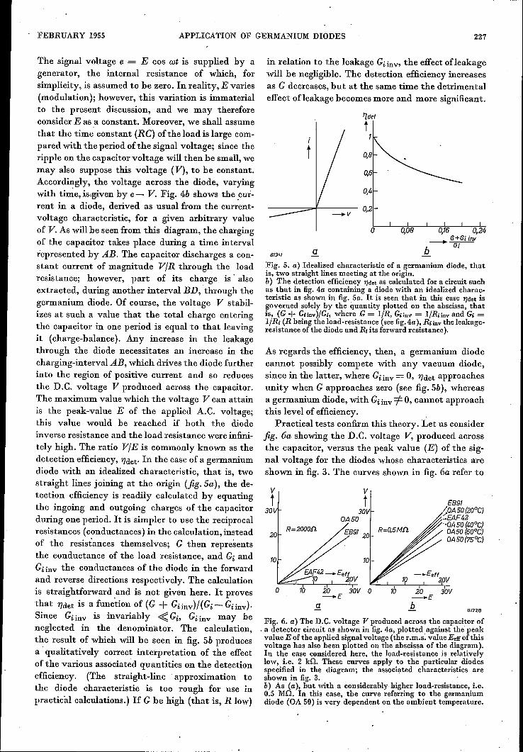
The signal voltage e = E cos wt is supplied by agenerator, the internal resistance of which, forsimplicity, is assumed to be zero. In reality, E varies(modulation); however, this variation is immaterialto the present discussion, and we may thereforeconsider E as a constant. Moreover, we shall assumethat the time constant (RC) of the load is large com-pared with the period of the signal voltage; since theripple on the capacitor voltage will then be small, wemayalso suppose this voltage (V), to be constant.Accordingly, the voltage across the diode, varyingwith tîme.ds.given by e - V. Fig. 4b shows the .cur-rent in a diode, derived as usual from the current-voltage characteristic, for a given arbitrary valueof V.As will he seen from this diagram, the chargingof the capacitor takes place during a time intervalrepresented by AB. The capacitor discharges a con-stant current of magnitude VIR through the loadresistance; however, part of its charge is' alsoextracted, during another interval BD, through thegermanium diode. Of course, the voltage V stabil-izes at such a value that the total charge enteringthe capacitor in one period is equal to that leavingit (charge-balance). Any increase in the leakagethrough the diode necessitates an increase in thecharging-interval AB, which drives the diode furtherinto the region of positive current and so reducesthe D.C. voltage V produced across the capacitor.The maximum value which the voltage V can attainis the peak-value E of the applied A.C. voltage;this value would be reached if both the diodeinverse resistance and the load resistance were infini-tely high. The ratio VIE is commonly known as thedetection efficiency, 'l]det. In the case of a germaniumdiode with an idealized characteristic, that is, twostraight lines joining at the origin (fig. Sa), the de-tection efficiency is readily calculated by equatingthe ingoing and outgoing charges of the capacitorduring one period. It is simpler to use the reciprocalresistances (conductances) in the calculation, insteadof the resistances themselves; G then representsthe conductance of the load resistance, and Gi andGi inv the conductances of the diode in the forwardand reverse directions respectively. The calculationis straightforward and is not given here. It provesthat 'l]det is a function of (G + Giinv)/(Gi - Giinv)'Since Gi inv is invariably <{ Gi, Giinv may heneglected in the denominator. The calculation,the result of which will be seen in fig. Sb producesa qualitatively correct interpretation of the effectof the various associated quantities on the detectionefficiency. (The straight-line approximation tothe diode characteristic is too rough for use inpractical calculations.) If G be high (that is, R low)
in relation to the leakage Gi inv- the effect ofleakagewill be negligible. The detection efficiency increasesas G decreases, but at the same time the detrimentaleffect ofleakage becomes more and more significant.
'Idet
t
o 0,08
813<1 aFig. 5. a) Idealized characteristic of a germanium diode, thatis, two straight lines meeting at the origin.b) The detection efficiency 1)det as calculated for a circuit suchas that in fig. 4a containing a diode with an idealized charac-teristic as shown in fig. Sa. It is seen that in this case 1)det isgoverned solely by the quantity plotted on the abscissa, thatis, (G + Giinv)/G;, where G = I/R, Giinv = ]/Riinv and Gi =I/Ri (R being the load-resistance (see figAa), Riinv the leakage-resistance ofthe diode and Ri its forward resistance).
As regards the efficiency, then, a germanium diodecannot possibly compete with any vacuum diode,since in the latter, where Giinv = 0, 'l]det approachesunity when G approaches zero (see fig. Sb), whereasa germanium diode, with Gi inv -=f 0, cannot approachthis level of efficiency.
Practical tests confirm this theory. Let us considerfig. 6a showing the D.C. voltage V, produced acrossthe capacitor, versus the peak value (E) of the sig-nal voltage for the diodes whose characteristics areshown in fig. 3. The curves shown in fig. 6a refer to
v
v~Î t E891
30V 30V <aA 50 (20CC)OA50 :'EAF42
'"OA50 (40°C)R=2000fl E891 R=O,5Mfl OA50(600C)20 20 OA50(75°C)
10 10
o 10 20 30V 0-E
la 20 30V- ...Eb
81228
Fig. 6. a) The D.C. voltage TI" produced across the capacitor of. a detector circuit as shown in fig. 4a, plotted. against the peakvalue E of the applied signal voltage (the r .m.s. value Eeffof thisvoltage has also been plotted on the abscissa of the diagram).In the case considered here, the load-resistance is relativelylow, i.e. 2 Hl. These curves apply to the partlcular diodesspecified in the diagram; the associated characteristics areshown in fig. 3. .b) As (a), but with a considerablyhlgher load-resistance, i.e.0.5 MO. In this case, the curve referring to the germaniumdiode (OA 50) is very dependent on the ambient temperature.

228 PHILlPS TECHNICAL REVIEW VOL. 16, No. 8
a low load-resistance, i.e. 2 ka. Their slight curva-ture arises from a deviation of the characteristicsfrom the idealized case (straight lines meeting atthe origin); Gi and Giinvare not constant, but dependupon the voltage across the diode. Owing to thiscurvature, the detection efficiency VIE increaseswith the signal voltage. It will be seen that byvirtue of. the low load-resistance employed, thefavourable forward characteristic of the germaniumdiode (high Gi) is reflected in a detection efficiencysuperior to those of the vacuum diodes.Here, then, the leakage of the germanium diode
does not impair its efficiency, as may be deducedfrom the fact that the curve appropriate to this diodeis independent of the ambient temperature. Althougha rise in temperature increases the leakage consi-derably, it has no appreciable effect on the forwardresistance; As follows from theory outlined above,the rate of increase of the detection efficiencywith the loàd resistance is higher in vacuum diodesthan in germanium diodes. Curves plotted at a verymuch higher load resistance, i.e. 0.5 Ma, are shownin fig. 6b. The leakage in the germanium diode thenplays an important part, as is evident from the factthat the detection efficiency decreases with risingambient temperature. There is no appreciable differ-ence in detection efficiency between the three diodesconsidered at temperatures up to 40°C.It should be noted that the germanium diode
type OA 50 is adopted as an example to illustratethe effect of a high load-resistance. In other diodes,e.g. types OA 51, OA 61 and OA 71, the leakageis very much smaller, and the detection efficiencyassociated with a high load-resistance is thereforehigher than in the above case.Another point illustrated by fig. 6 which should be
mentioned in passing, is that the diode part of theEAF 42 must not be operated with a low load-resistance; it is, in fact, designed to operate witha load of the order of 0.5 Ma.
Equivalent attenuation resistance
An important factor in-many circuits, apart fromthe detection efficiency, is the power extracted fromthe voltage source, In so far as the power' absorbeddepends on the detector circuit (it also depends, ofcourse, on the magnitude ~f the signal voltage), it isusually defined in terms of the so-called equivalentattenuation resistance (Rd)' This is the resistancewhich, if substituted for the detector circuit, woulddraw the same amount of power from the voltagesource. If P be the power so extracted and E thepeak voltage supplied by the particular source, the
equivalent attenuation resistance Rd is defined bythe equation:
E2-= P (1)2Rd
Given a circuit as shown in fig. 4a with both theload-resistance (R) and the diode leakage-resistance(Ri inv) high in relation to the diode forward resis-tance (Ri), the approximate value of Rd is readilyevaluated. In this case (to be precise, when RandRiinv are infinitely high), the D.C. voltage producedacr~ss the capacitor (V) is E (with"1Jdêt= 1); thepower dissipated in R is then E2/R. Accordingly, asmall current flows during the very short forwardperiod (see fig. 4b); however, we shall ignore thepower dissipated by this current in the forwardresistance, The voltage across Riinv is now, duringvirtually the whole period, given by E (-1 + coswt),so that the power dissipated in R; inv is t E2/Riinv·Hence P ~ E2(1/R + 3/2 Riinv), and it follows, withthe aid of (1), that:
l/Rd ~ 2/R + 3/Riinv. (2)
Accordingly, the equivalent attenuation resis-tance of a vacuum diode (Ri inv = 00) is roughlyequal to half the load-resistance, whereas in the caseof a germanium diode (Ri inv =f 00) the resistanceRd is equal to half the load-resistance and a third ofthe diode leakage-resistance in parallel.
Fig. 7 shows the calculated equivalent attenua-tion conductance Gd (= I/Rd) versus the loadconductance G (= l/R), for different values of theleakage conductance Giinv (= I/Riinv), in the caseof an idealized diode characteristic consisting ofstraight lines (constant forward and leakage resis-tances). The approximation involved in the aboveargument means that the tangents to the starting-points of the curves, seen at the bottom left-handside of the diagram, are used instead of the curvesthemselves.It is seen that the effect of increasing load and of
increasing leakage upon the attenuation is notquite as serious as formula (2) suggests; however,this does not detract from the practical validity ofthis formula.
A difficulty in applying the formula arises fromthe fact that, as can be seen from the characteristicsof the germanium diodes, the leakage resistance isgoverned by the voltage. Hence the average leakage-resistance appropriate to a given peak voltage mustbe estimated from the characteristic.
An increase in the signal voltage relative to zerowill at first produce an increase in the averageleakage resistance; but if the sig~al voltage increases

FEBRUARY 1955 APPLICATION OF GERMANIUM DIODES 229
far enough, it will diminish again (fig. 3b). Accor-dingly, a high signal voltage and a high ambienttemperature, both of which reduce the leakage resist-ancc, impair the efficiency of a germanium diode.
Fig. 7. Calculated attenuation conductance (Gd =~ I/Rd)versus the load conductance (G = I/R), for various values ofthe leakage conductance (Giinv = lfRiinv), in the caseof a diodewith the characteristic shown in fig. Sa. As in fig. Sb, all thequantities involved are expressed in terms of Gi (= I/Ri), thatis, the forward conductance of the diode. To obtain the curveappropriate to a given value ofGiinv/Gi, transfer the Giinv/Gi =0curve a distance equivalent to the particular value of Giinv/Gi,first to the left, and then the same distance upwards.
From (2), if the load-resistance he reduced, theextra attenuation arising from leakage will becomeless important; in fact, given a sufficiently drasticreduction, it will be possible to substitute a german-ium diode for a vacuum diode with virtually nochange in attenuation. Practical experience hasshown that the difference in attenuation becomesnegligible at a load-resistance of some ten-thousandsof ohms. Of course, the precise load-resistance toproduce this effect depends UponRiinv, which, in turn,depends upon the particular type of germaniumdiode, and upon the ambient température and theappliedA.C. voltage. Now, givena load-resistance ofthe above-mentioned order of magnitude, the detect-ion efficiency of the various types of germaniumdiode, and that of the vacuum diode type EB 91, willall he in the region of 100%; hence there willbe virtu-ally no difference in performance between a~y ofthem. However, anyfurtherreduction ofR will affectboth the attenuation and the detection efficiency un-favourably. Whereas the equivalent attenuationresistance ofany' diode will then remain equal to halfthe load-resistance, the higher forward resistanceof the germanium diode, as we have already seen,
will give it a detection efficiency superior to thatof the vacuum diode.The above argument only holds good for a vacuum
diode whose forward resistance is not unduly liigh.Given a vacuum diode having a high forward resis-tance, e.g. the EAF 42, the situation will he morecomplex because, amongst other reasons, such a valveoperates in a range perceptibly affected by deviationsfrom formula (2) (see fig. 7, bearing in mind thatGi is now low).Provided that the signal voltage is low (< 0·5 Veff)
and the ambient temperature is not unduly high,it is usually possible to procure a better detectionefficiency and less attenuation with germaniumdiodes than with vacuum diodes. The reason forthis is that, under these conditions, vacuum diodesoperate in the starting-current region; here thedetection efficiency and the equivalent attenuationresistance are both low, and the relation Rd = tRno longer holds good in this region. However, thebehaviour of vacuum diodes under these conditionswill not be pursued here.In the region between 0 and about 10 fLV, there
is no difference in slope between the forward andreverse characteristics of a germanium diode; whichthen behaves likê an ordinary resistor, that is,without rectification.That the germanium diode is particularly suitable
for use in circuits where the load resistance is fairlylow and the signal voltage .and ambient temperaturenot unduly high can be deduced from the aboveargument. However, the other advantages of thegermanium diode as mentioned on the opening pageofthis article frequently turn the scale in its favoureven in cases where the electrical properties of thisdiode do not match those of the vacuum diode.
Performance at high frequencies
The efficiency of a germanium diode.as a detectorat high frequencies (> about 40 Mcls) cannot beproperly predicted from the static characteristic.We have already seen something of the nature of theeffects ("hole storage") precluding such a predictionin the preceding article 1).We shall now illustrate, with the aid of one or two
practical examples, how these effects modify theperformance of a germanium diode in a practicalcircuit. The values referred to are the results of testson a TV video detector circuit containing a 3.9 kGload-resistor shunted by a capacitor ofroughly 20 pF.Given a germanium diode type OA50, and a signalof r.m.s. voltage 5 V, the measured detectionefficiency of this circuit is 0.62 at 30 Mcls and0.605 at 70 Mc/s.

230 PIULIPS TECHNICAL REVIEW VOL. 16, No. 8
The first thing that we notice about these values isthat the detect efficiency is quite low at bothfrequencies. This is partly attributable to the factthat, particularly at 30 Mc/s, the time constant ofthe load is not very long compared to one cycle;it is also attributable to the self-capacitance of thediode, owing to which an appreciable part of theH.F. voltage occurs across the load (20 pF). Thedifference in the detection efficiency as between thetwo frequencies is only small but the difference inthe attenuation caused by the detector circuit in thecircuit immediately preceding it is considerable: theequivalent attenuation resistance is 2400 n at30Mc/s and 1450n at 70 Mc/s. Since the D.C.voltageacross the load-resistance and therefore the powerdissipated in it is very much the same in both cases,the relatively greater attenuation at 70 Mc/s mustbe attributed to extra losses in the germanium diode.In a TV receiver, such strong attenuation detractsfrom the gain of the amplifier stage preceding thedetector; moreover, owing to the variation inattenuation between individual diodes of the sametype, it is responsible for variations in the am-plification and in the frequency characteristic ofproduction receivers.It is also worth mentioning that the decline in
performance at relatively high frequencies is all themore noticeable according as the load-resistance isincreased.
Examples illustrating the use of diodes for specialpurposes
As we may conclude from the above, the ger-manium diode may be substituted for the vacuumdiode in a very large number of cases. At the sametime, the leakage exhibited by the germanium diode,must often be taken into account in the design of a
:~::~-g~~~,.~i :451;-;';f--!--I--!--+-lf-201-- :455 ~:451 ..
:456 I1--!--I--!--I---I---I---!--+-1-151-- :471 ,
JÀ61ry;V/10 .z~.
1--!-~1-+-+--1---+--1---+-l-5~/~~~'/~'+-~-1~V-90 -80 -70 -60 -50 -/,O -JO -20 -10 .P'/
Fig. 8. The characteristics of various types of germanium diode.
particular circuit. With this reservation, however,there is freedom of choice from several types,according to the particular application envisaged;these include types oflow leakage and high maximumreverse voltage (fig. 8).
Video detectionFig. 9 is the circuit diagram of a video detector
employing a germanium diode, i.e. type OA 60 ortype OA 70. As we have already seen, these diodesare specially designed for use in such a circuit. In thecase here considered, the operating frequency is.24 Mc/s and the signal voltage in the I.F. circuit(L2-C2) is 5 V r.m.s.; the detection efficiency is then
OA60(OA70)
82212
Fig. 9. Video circuit containing a germanium diode type OA 60or OA 70.
about 70% that is, the D.C. voltage generatedacross the 3·9 kn load-resistor (R) is about 5 V.The equivalent resistance of the detector circuitis about 3 kO.
nr------.-------,------.-------,loo%f=30McjsR=3,9kll
80
~ q~
Î 61----\\016''-1----1---1----160 Î
20
O~----~~----~~----~~----_=~O1.5 15 150 1500 15000pF
83675 -+C
Fig. 10. Effect of the load-capacitance C on the detection ef-ficiency 1)dct and equivalent attenuation resistance (Rd) of thevideo detector circuit shown in fig. 9. These quantities alsodepend upon the tuning capacitance C2; the curves for severalvalues of this parameter are given. The curves are valid for acarrier-wave frequency of 30 McJs and a load-resistance R of3.9 kno

FEBRUARY 1955 APPLICATION OF GERMANIUM DIODES 231
The detection efficiency and the attenuation arealso affected by the total tuning capacitance (e2)
of the circuit (see jig. 10), which, in the diagramshown in fig. 9, comprises the self-capacitance of thecoils and the valve and wiring capacitances (total-ling about 17 pF in all).
D.e. restoration
Fig. lla shows a circuit employed to fix the blacklevel in the signal applied to the picture tube of a. television receiver. 'I'his circuit includes a germa-nium diode, type OA 61 or type OA 71, speciallydesigned for the purpose and exhibiting only a smallamount of leakage even when operated with a highreverse voltage.
Ra
lf:+------,
81512
exactly to any rapid variations in VI (potential at point I).However, as soon as Vz drops below Va' as it does during the
application of a synchronizing pulse (fig. lle), the diodebecomes conductive, A charging current then flows to C sothat, at the end of the sync. pulse, Vz (which is also the control-grid potentialof the picture tube W) is raised to the fixedvalue represented by v3• Potential VI then increases again,thus initiating the next line period, during which Vz againresponds almost exactly to the variations of Vl' Owing to thefact that a small proportion of the charge of C leaks awaythrough Rl during the line period, voltage Vz again drops belowV3 at the next sync pulse; however, this leakage is made goodand a new line period starts from, V3 (fig. lle). The necessityof ensuring that V2 will drop below V3 during each synchronisingpulse imposes a maximum limit on the size of Rl'The direct current flowing in potentiometer R causes Va
to assume a certain value below the cathode potential; hencethis potentiometer can be used to vary V3 and so adjust the
ia
t
V~t ....
"'"Vz Va ' ,,:...._..~ -----
_t
_Vg
Fig. 11. a) D.C. restorer circuit employed to fix the black level of the signal applied to thepicture tube W of a television receiver.b) Video signal with line-synchronizing pulses, as applied to the grid of the picture tubewhen the diode shown in (a) is omitted. In practice, the variation of the sync. pulse pcaksis much more gradual than this diagram suggests.e) Video signalon the grid of the picture tube (fullline). Each line-period starts at a fixedvaluc (v.) corresponding to the pro-adjusted black level of the picture tube. The dottedline represents the signal as it would be if not corrected by the diode and the resistor RI'd) The video signal referred to the ia-Vg characteristic of the picture tube. With the aid ofpotentiometer R(see (a», va is so adjusted that Vz (the black level) coincides roughly withthe cut-off point of the tube-characteristic.
The action of such a circuit will be explained here for thoseunfamiliar with TV circuit technique. Fig. llb shows roughlywhat the shape of the video signalon the grid of the picturetube would be in the absence of a diode. The upper ends ofthe sync. pulses, which correspond to black in the scene tele-vised, should remain at a constant level in order that black inthe scene will always give rise to the same degree of blacknesson the picture tube. However, it will be seen that these peaksrise and fall with the average picture-content of the video signalpreceding them. Accordingly, the task of the circuit shownin fig. Ila is to fix the black level at the start of each line period,thus correcting any variation in this level introduced duringthe preceding line period, that is, preventing any cumulativevariation. Because the depth of the synchronizing pulses isconstant, it is sufficient to maintain the bases of these pulsesat a fixed level. This is achieved as follows.As long as the potential (vz) of the hottorn plate of
capacitor C remains above the potential at point 3 (v3),the diode remains non-conductive. Owingto the high resistanceof Rl' the charge and potential difference of the capacitorC can vary only gradually; hence Vz must respond almost
black level of the picture tube to a particular fixed value(fig. lld).
If much of the charge of capacitor e leaks awaythrough the diode in the interval between twosuccessive sync. pulses, the grid voltage (v2) of thepicture tube (W) will already have fallen well belowthe pre-adjusted black level (vz) by the time thesecond sync. pulse arrives (fig.lle). One detrimentaleffect of this premature drop in Vz is that the side ofthe picture at which the raster-lines end becomesdarker than the side where these lines start. Thereis, however, still another, more serious disadvan-tage. With such a drop, the diode becomes conduc-tive, and therefore the charging of e commencesbefore the sync. pulse is fully developed. Instead offlowing in Ra, as under ordinary conditions, thegreater part of the anode current of valve P then

232 PHILIPS TECHNICAL REVIEW VOL. 16, No. 8
SEDIMENTATION OF FLUORESCENT SCREENSIN CATHODE RAY TUBES
takes the line of least resistance through C, thusreducing the amplification ofthe valve abruptly andconsiderably. As long as the charging currentcontinues to flow - that is, during à considerablepart, if not the whole, of the pulse period (since theconsiderable amount of charge at first releasedmust now be made good) - the pulse is unable todevelop to its full height and is therefore distortedand attenuated. This effect may attain such propor-tions as:to upset the synchronization of the picture·.
This explains why it is necessary in this applica-tion to employ a diode exhibiting only a smallleakage at the high reverse voltages involved.
Summary. Among the obvious advantages' of germaniumdiodes compared with their vacuum equivalents, are theirrelatively small size and weight and the fact that they containno filament. As regards the normal functions of a diode, that is,rectification and detection, the leakage current of thegermanium diode and its superior forward characteristic,constitute the most striking differences between it and thevacuum diode. The 'effect of these differences upon thedetection efficiency and equivalent attenuation resistancein a detector circuit is investigated. It is shown thatgermanium diodes can he employed in a very large number ofcasesand that, provided that the load-resistance is low and thesignal voltage and ambient temperature are not unduly high,the performance of such a diode is even better than that of avacuum diode. Special germanium diodes have been developedfor certain purposes, e.g. to operate at high frequencies (videodetection in a television receiver) and for use as D.C. restorersfor maintaining the black level in the picture tube of a TVreceiver.
by F. de BOER and H. EMMENS.
The ever-increasing use of cathode ray tubes for television and other purposes creates theneed for a sufficiently reproducible method of forming the fluorescent screen in the tube. Theproblems thereby involved are largely of a colloid-chemical nature. A detailed study of theeffects occurring on sedimentation of the screen is possible only if the chemical composition.of the layer is known. This composition can be determined with the aid of radio-active tracers.
535.371.07: 621.385.832
Introduetion
The fluorescent screens of picture-tubes and othertypes of cathode ray tube are composed of a mixtureof substances. The fluorescent substance itself, theso-called phosphor, of course predominates, but forthe deposition of the screen it is necessary to includea number of components to ensure a sufficientlyadhesive and finely grained layer. These admixturesaffect the characteristics of the screen, such as thesecondary emission factor. If this is too low, heavynegative charging of the (insulated) screen willoccur during use, to the detriment of the luminousefficiency and fidelity of reproduetion 1). On theother hand, the content of non-fluorescent substancesmust not be too high, as this also has an unfavour-able effect on the fluorescent efficiency. It is there-fore necessary to select and apportion the additionalconstituents with care.The method ofpreparation of fluorescent mixtures
nowadays employed is as follows. The fluorescentgrains are suspended in water containing waterglass
1) See for example J. de Gier, A. C. Kleisma and J. Peper,Secondary emission from the screen of a picture tube,Philips tech. Rev. 16, 26-32, 1954/55.
(a colloidal solution of potassium silicate in waterwith excess silièa). Agelatinising agent is also added.This suspension is poured into the tube and, after acertain time, the powder settles to form a uniform,closely adhering layer, the solvent being then pouredoff. Fig. 1 shows how this is done in manufacture.The use of a gelatinising agent is necessary to
prevent the layer of sediment from sliding to oneside and also to prevent individual granules frombecoming detached, when the tube is tilted in thedecanting process. Moreover, in the dry condition,during exhaustion of the tube as well as during use,effective adhesion of the granules must be guaran-teed; the presence of loose granules in a tube opera-ted at high voltages must be avoided at all costs.Until a few years ago the gelatinising medium
used was potassium sulphate, but a disadvantage ofthis "sulphate" method is that it takes some timeto produce a sufficiently adhesive layer, viz. 1 to2 hours. A more rapidly reacting medium wastherefore sought. Such a medium was found amongcertain soluble calcium or barium salts, of whichbarium nitrate, for example, produces a firmly