Embed Size (px)
Citation preview

The beams supporting the multiple
overhead cranes system shown in this
picture are subjected to transverse
loads causing the beams to bend. The
normal stresses resulting from such
loadings will be determined in this
chapter.
314
bee80288_ch05_314-379.indd Page 314 10/27/10 9:48:37 PM user-f499bee80288_ch05_314-379.indd Page 314 10/27/10 9:48:37 PM user-f499 /Volumes/201/MHDQ251/bee80288_disk1of1/0073380288/bee80288_pagefiles/Volumes/201/MHDQ251/bee80288_disk1of1/0073380288/bee80288_pagefiles

C H A P T E R
315
Analysis and Design of Beams for Bending
bee80288_ch05_314-379.indd Page 315 10/27/10 9:50:57 PM user-f499bee80288_ch05_314-379.indd Page 315 10/27/10 9:50:57 PM user-f499 /Volumes/201/MHDQ251/bee80288_disk1of1/0073380288/bee80288_pagefiles/Volumes/201/MHDQ251/bee80288_disk1of1/0073380288/bee80288_pagefiles

316
Chapter 5 Analysis and Design of Beams for Bending
5.1 Introduction 5.2 Shear and Bending-Moment
Diagrams 5.3 Relations Among Load, Shear,
and Bending Moment 5.4 Design of Prismatic Beams for
Bending *5.5 Using Singularity Functions to
Determine Shear and Bending Moment in a Beam
*5.6 Nonprismatic Beams
5.1 INTRODUCTIONThis chapter and most of the next one will be devoted to the analysis and the design of beams, i.e., structural members supporting loads applied at various points along the member. Beams are usually long, straight prismatic members, as shown in the photo on the previous page. Steel and aluminum beams play an important part in both struc-tural and mechanical engineering. Timber beams are widely used in home construction (Photo 5.1). In most cases, the loads are perpen-dicular to the axis of the beam. Such a transverse loading causes only bending and shear in the beam. When the loads are not at a right angle to the beam, they also produce axial forces in the beam.
Photo 5.1 Timber beams used in residential dwelling.
CB
P1
(a) Concentrated loads
w
P2
A D
(b) Distributed load
AB
C
Fig. 5.1 Transversely loaded beams.
The transverse loading of a beam may consist of concentrated loads P1, P2, . . . , expressed in newtons, pounds, or their multiples, kilonewtons and kips (Fig. 5.1a), of a distributed load w, expressed in N/m, kN/m, lb/ft, or kips/ft (Fig. 5.1b), or of a combination of both. When the load w per unit length has a constant value over part of the beam (as between A and B in Fig. 5.1b), the load is said to be uniformly distributed over that part of the beam. Beams are classified according to the way in which they are supported. Several types of beams frequently used are shown in Fig. 5.2. The distance L shown in the various parts of the figure is
Fig. 5.2 Common beam support configurations.
L
(a) Simply supported beam
StaticallyDeterminateBeams
StaticallyIndeterminateBeams
L2L1
(d) Continuous beam
L
(b) Overhanging beam
L
Beam fixed at one endand simply supported
at the other end
(e)
L
(c) Cantilever beam
L
( f ) Fixed beam
bee80288_ch05_314-379.indd Page 316 10/29/10 7:07:38 PM user-f499bee80288_ch05_314-379.indd Page 316 10/29/10 7:07:38 PM user-f499 /Volumes/201/MHDQ251/bee80288_disk1of1/0073380288/bee80288_pagefiles/Volumes/201/MHDQ251/bee80288_disk1of1/0073380288/bee80288_pagefiles

317called the span. Note that the reactions at the supports of the beams in parts a, b, and c of the figure involve a total of only three unknowns and, therefore, can be determined by the methods of statics. Such beams are said to be statically determinate and will be discussed in this chapter and the next. On the other hand, the reactions at the supports of the beams in parts d, e, and f of Fig. 5.2 involve more than three unknowns and cannot be determined by the methods of statics alone. The properties of the beams with regard to their resistance to deformations must be taken into consideration. Such beams are said to be statically indeterminate and their analysis will be postponed until Chap. 9, where deformations of beams will be discussed. Sometimes two or more beams are connected by hinges to form a single continuous structure. Two examples of beams hinged at a point H are shown in Fig. 5.3. It will be noted that the reactions at the supports involve four unknowns and cannot be determined from the free-body diagram of the two-beam system. They can be determined, however, by recognizing that the internal moment at the hinge is zero. Then, after considering the free-body diagram of each beam separately, six unknowns are involved (including two force components at the hinge), and six equations are available. When a beam is subjected to transverse loads, the internal forces in any section of the beam will generally consist of a shear force V and a bending couple M. Consider, for example, a simply supported beam AB carrying two concentrated loads and a uniformly distributed load (Fig. 5.4a). To determine the internal forces in a section through point C we first draw the free-body diagram of the entire beam to obtain the reactions at the supports (Fig. 5.4b). Pass-ing a section through C, we then draw the free-body diagram of AC (Fig. 5.4c), from which we determine the shear force V and the bending couple M. The bending couple M creates normal stresses in the cross sec-tion, while the shear force V creates shearing stresses in that section. In most cases the dominant criterion in the design of a beam for strength is the maximum value of the normal stress in the beam. The determination of the normal stresses in a beam will be the subject of this chapter, while shearing stresses will be discussed in Chap. 6. Since the distribution of the normal stresses in a given section depends only upon the value of the bending moment M in that sec-tion and the geometry of the section,† the elastic flexure formulas derived in Sec. 4.4 can be used to determine the maximum stress, as well as the stress at any given point, in the section. We write‡
sm 5
ZMZc
I sx 5 2
My
I (5.1, 5.2)
5.1 Introduction
†It is assumed that the distribution of the normal stresses in a given cross section is not affected by the deformations caused by the shearing stresses. This assumption will be verified in Sec. 6.5.‡We recall from Sec. 4.2 that M can be positive or negative, depending upon whether the concavity of the beam at the point considered faces upward or downward. Thus, in the case considered here of a transverse loading, the sign of M can vary along the beam. On the other hand, since sm is a positive quantity, the absolute value of M is used in Eq. (5.1).
B
C
A
w
a
P1 P2
(a) Transversely-loaded beam
BC
C
A
wP1
RA RB
P2
(b) Free-body diagram to findsupport reactions
A
waP1
V
M
RA
(c) Free-body diagram to findinternal forces at C
Fig. 5.4 Analysis of a simply supported beam.
BH
(a)
A
CB
H
(b)
A
Fig. 5.3 Beams connected by hinges.
bee80288_ch05_314-379.indd Page 317 11/12/10 7:30:37 PM user-f499bee80288_ch05_314-379.indd Page 317 11/12/10 7:30:37 PM user-f499 /Users/user-f499/Desktop/Temp Work/Don't Delete Job/MHDQ251:Beer:201/ch05/Users/user-f499/Desktop/Temp Work/Don't Delete Job/MHDQ251:Beer:201/ch05

318 Analysis and Design of Beams for Bending where I is the moment of inertia of the cross section with respect to a centroidal axis perpendicular to the plane of the couple, y is the distance from the neutral surface, and c is the maximum value of that distance (Fig. 4.11). We also recall from Sec. 4.4 that, introducing the elastic section modulus S 5 Iyc of the beam, the maximum value sm of the normal stress in the section can be expressed as
sm 5
ZMZ
S (5.3)
The fact that sm is inversely proportional to S underlines the impor-tance of selecting beams with a large section modulus. Section mod-uli of various rolled-steel shapes are given in Appendix C, while the section modulus of a rectangular shape can be expressed, as shown in Sec. 4.4, as
S 5 16 bh2 (5.4)
where b and h are, respectively, the width and the depth of the cross section. Equation (5.3) also shows that, for a beam of uniform cross section, sm is proportional to |M|: Thus, the maximum value of the normal stress in the beam occurs in the section where |M| is largest. It follows that one of the most important parts of the design of a beam for a given loading condition is the determination of the loca-tion and magnitude of the largest bending moment. This task is made easier if a bending-moment diagram is drawn, i.e., if the value of the bending moment M is determined at various points of the beam and plotted against the distance x measured from one end of the beam. It is further facilitated if a shear diagram is drawn at the same time by plotting the shear V against x. The sign convention to be used to record the values of the shear and bending moment will be discussed in Sec. 5.2. The values of V and M will then be obtained at various points of the beam by drawing free-body diagrams of successive portions of the beam. In Sec. 5.3 relations among load, shear, and bending moment will be derived and used to obtain the shear and bending-moment diagrams. This approach facilitates the determination of the largest absolute value of the bending moment and, thus, the determination of the maximum normal stress in the beam. In Sec. 5.4 you will learn to design a beam for bending, i.e., so that the maximum normal stress in the beam will not exceed its allowable value. As indicated earlier, this is the dominant criterion in the design of a beam. Another method for the determination of the maximum values of the shear and bending moment, based on expressing V and M in terms of singularity functions, will be discussed in Sec. 5.5. This approach lends itself well to the use of computers and will be expanded in Chap. 9 to facilitate the determination of the slope and deflection of beams. Finally, the design of nonprismatic beams, i.e., beams with a variable cross section, will be discussed in Sec. 5.6. By selecting
bee80288_ch05_314-379.indd Page 318 10/27/10 9:51:23 PM user-f499bee80288_ch05_314-379.indd Page 318 10/27/10 9:51:23 PM user-f499 /Volumes/201/MHDQ251/bee80288_disk1of1/0073380288/bee80288_pagefiles/Volumes/201/MHDQ251/bee80288_disk1of1/0073380288/bee80288_pagefiles

319the shape and size of the variable cross section so that its elastic section modulus S 5 Iyc varies along the length of the beam in the same way as |M|, it is possible to design beams for which the maximum normal stress in each section is equal to the allowable stress of the material. Such beams are said to be of constant strength.
5.2 SHEAR AND BENDING-MOMENT DIAGRAMSAs indicated in Sec. 5.1, the determination of the maximum absolute values of the shear and of the bending moment in a beam are greatly facilitated if V and M are plotted against the distance x measured from one end of the beam. Besides, as you will see in Chap. 9, the knowledge of M as a function of x is essential to the determination of the deflection of a beam. In the examples and sample problems of this section, the shear and bending-moment diagrams will be obtained by determin-ing the values of V and M at selected points of the beam. These values will be found in the usual way, i.e., by passing a section through the point where they are to be determined (Fig. 5.5a) and considering the equilibrium of the portion of beam located on either side of the section (Fig. 5.5b). Since the shear forces V and V9 have opposite senses, recording the shear at point C with an up or down arrow would be meaningless, unless we indicated at the same time which of the free bodies AC and CB we are consid-ering. For this reason, the shear V will be recorded with a sign: a plus sign if the shearing forces are directed as shown in Fig. 5.5b, and a minus sign otherwise. A similar convention will apply for the bending moment M. It will be considered as positive if the bending couples are directed as shown in that figure, and negative otherwise.† Summarizing the sign conventions we have presented, we state: The shear V and the bending moment M at a given point of a beam are said to be positive when the internal forces and couples act-ing on each portion of the beam are directed as shown in Fig. 5.6a. These conventions can be more easily remembered if we note that
1. The shear at any given point of a beam is positive when the external forces (loads and reactions) acting on the beam tend to shear off the beam at that point as indicated in Fig. 5.6b.
†Note that this convention is the same that we used earlier in Sec. 4.2
BC
A
w
x
P1 P2
(a)
C
B
C
A
wP1
RA
(b)V
M
P2
RB
M'
V'
Fig. 5.5 Determination of V and M.
5.2 Shear and Bending-Moment Diagrams
V
M
M'
V'
(a) Internal forces(positive shear and positive bending moment)
(b) Effect of external forces(positive shear)
(c) Effect of external forces(positive bending moment)
Fig. 5.6 Sign convention for shear and bending moment.
bee80288_ch05_314-379.indd Page 319 10/27/10 9:51:23 PM user-f499bee80288_ch05_314-379.indd Page 319 10/27/10 9:51:23 PM user-f499 /Volumes/201/MHDQ251/bee80288_disk1of1/0073380288/bee80288_pagefiles/Volumes/201/MHDQ251/bee80288_disk1of1/0073380288/bee80288_pagefiles

320 Analysis and Design of Beams for Bending
Draw the shear and bending-moment diagrams for a simply supported beam AB of span L subjected to a single concentrated load P at its mid-point C (Fig. 5.7).
EXAMPLE 5.01
BC
A
P
L12 L1
2
Fig. 5.7
Fig. 5.8
RA� P12
RA� P12 RB� P1
2
PL
x
14
RB� P12
BC ED
A
PL1
2 L12
BC
D
D
A
x
x
x
P
(a)
(b)
VM
M'
V'
RA� P12
L12
L L12
P� 12
P12
RB� P12
B
C E
EL � x
L
M
V
A
P
(c)
(d)
(e)
V
M
M'
V'
We first determine the reactions at the supports from the free-body diagram of the entire beam (Fig. 5.8a); we find that the magnitude of each reaction is equal to Py2.
Next we cut the beam at a point D between A and C and draw the free-body diagrams of AD and DB (Fig. 5.8b). Assuming that shear and bending moment are positive, we direct the internal forces V and V9 and the internal couples M and M9 as indicated in Fig. 5.6a. Considering the free body AD and writing that the sum of the vertical components and the sum of the moments about D of the forces acting on the free body are zero, we find V 5 1Py2 and M 5 1Pxy2. Both the shear and the bending moment are therefore positive; this may be checked by observing that the reaction at A tends to shear off and to bend the beam at D as indicated in Figs. 5.6b and c. We now plot V and M between A and C (Figs. 5.8d and e); the shear has a constant value V 5 Py2, while the bending moment increases linearly from M 5 0 at x 5 0 to M 5 PLy4 at x 5 Ly2.
Cutting, now, the beam at a point E between C and B and consider-ing the free body EB (Fig. 5.8c), we write that the sum of the vertical components and the sum of the moments about E of the forces acting on the free body are zero. We obtain V 5 2Py2 and M 5 P(L 2 x)y2. The shear is therefore negative and the bending moment positive; this can be checked by observing that the reaction at B bends the beam at E as indicated in Fig. 5.6c but tends to shear it off in a manner opposite to that shown in Fig. 5.6b. We can complete, now, the shear and bending-moment diagrams of Figs. 5.8d and e; the shear has a constant value V 5 2Py2 between C and B, while the bending moment decreases linearly from M 5 PLy4 at x 5 Ly2 to M 5 0 at x 5 L.
2. The bending moment at any given point of a beam is positive when the external forces acting on the beam tend to bend the beam at that point as indicated in Fig. 5.6c.
It is also of help to note that the situation described in Fig. 5.6, in which the values of the shear and of the bending moment are positive, is precisely the situation that occurs in the left half of a simply supported beam carrying a single concentrated load at its mid-point. This particular case is fully discussed in the next example.
bee80288_ch05_314-379.indd Page 320 10/27/10 9:51:28 PM user-f499bee80288_ch05_314-379.indd Page 320 10/27/10 9:51:28 PM user-f499 /Volumes/201/MHDQ251/bee80288_disk1of1/0073380288/bee80288_pagefiles/Volumes/201/MHDQ251/bee80288_disk1of1/0073380288/bee80288_pagefiles
321 We note from the foregoing example that, when a beam is subjected only to concentrated loads, the shear is constant between loads and the bending moment varies linearly between loads. In such situations, therefore, the shear and bending-moment diagrams can easily be drawn, once the values of V and M have been obtained at sections selected just to the left and just to the right of the points where the loads and reactions are applied (see Sample Prob. 5.1).
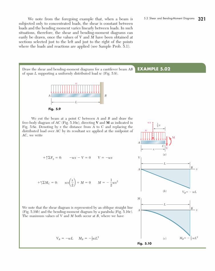
EXAMPLE 5.02Draw the shear and bending-moment diagrams for a cantilever beam AB of span L supporting a uniformly distributed load w (Fig. 5.9).
L
A B
w
Fig. 5.9
Fig. 5.10
x12
VB� � wL
(a)
V
M
MB� � wL212
x
x
A
V
A
C
w
wx
(b)
LB
x
M
A
(c)
LB
We cut the beam at a point C between A and B and draw the free-body diagram of AC (Fig. 5.10a), directing V and M as indicated in Fig. 5.6a. Denoting by x the distance from A to C and replacing the distributed load over AC by its resultant wx applied at the midpoint of AC, we write
1x©Fy 5 0: 2wx 2 V 5 0 V 5 2wx
1 l©MC 5 0: wx a x2b 1 M 5 0 M 5 2
12
wx2
We note that the shear diagram is represented by an oblique straight line (Fig. 5.10b) and the bending-moment diagram by a parabola (Fig. 5.10c). The maximum values of V and M both occur at B, where we have
VB 5 2wL MB 5 212wL2
5.2 Shear and Bending-Moment Diagrams
bee80288_ch05_314-379.indd Page 321 11/12/10 7:30:42 PM user-f499bee80288_ch05_314-379.indd Page 321 11/12/10 7:30:42 PM user-f499 /Users/user-f499/Desktop/Temp Work/Don't Delete Job/MHDQ251:Beer:201/ch05/Users/user-f499/Desktop/Temp Work/Don't Delete Job/MHDQ251:Beer:201/ch05

322
SAMPLE PROBLEM 5.1
For the timber beam and loading shown, draw the shear and bending-moment diagrams and determine the maximum normal stress due to bending.
SOLUTION
Reactions. Considering the entire beam as a free body, we find
RB 5 40 kNx RD 5 14 kNx
Shear and Bending-Moment Diagrams. We first determine the internal forces just to the right of the 20-kN load at A. Considering the stub of beam to the left of section 1 as a free body and assuming V and M to be positive (according to the standard convention), we write
1x©Fy 5 0 : 220 kN 2 V1 5 0 V1 5 220 kN 1l©M1 5 0 : 120 kN 2 10 m 2 1 M1 5 0 M1 5 0
We next consider as a free body the portion of beam to the left of section 2 and write
1x©Fy 5 0 : 220 kN 2 V2 5 0 V2 5 220 kN 1l©M2 5 0 : 120 kN2 12.5 m2 1 M2 5 0 M2 5 250 kN ? m
The shear and bending moment at sections 3, 4, 5, and 6 are deter-mined in a similar way from the free-body diagrams shown. We obtain
V3 5 126 kN M3 5 250 kN ? m V4 5 126 kN M4 5 128 kN ? m V5 5 214 kN M5 5 128 kN ? m V6 5 214 kN M6 5 0
For several of the latter sections, the results may be more easily obtained by considering as a free body the portion of the beam to the right of the section. For example, for the portion of the beam to the right of section 4, we have
1x©Fy 5 0 : V4 2 40 kN 1 14 kN 5 0 V4 5 126 kN 1l©M4 5 0 : 2M4 1 114 kN2 12 m2 5 0 M4 5 128 kN ? m
We can now plot the six points shown on the shear and bending-moment diagrams. As indicated earlier in this section, the shear is of constant value between concentrated loads, and the bending moment varies linearly; we obtain therefore the shear and bending-moment diagrams shown.
Maximum Normal Stress. It occurs at B, where |M| is largest. We use Eq. (5.4) to determine the section modulus of the beam:
S 5 16bh2 5 1
6 10.080 m2 10.250 m22 5 833.33 3 1026 m3
Substituting this value and |M| 5 |MB| 5 50 3 103 N ? m into Eq. (5.3) gives
sm 5ZMBZ
S5150 3 103 N ? m2
833.33 3 1026 5 60.00 3 106 Pa
Maximum normal stress in the beam 5 60.0 MPa ◀
B
2.5 m 3 m 2 m
250 mm
80 mm
CDA
20 kN 40 kN
B
1 3 52 64
2.5 m 3 m 2 m
C
DA
20 kN
20 kN
2.5 m 3 m 2 m
40 kN
14 kN46 kN
M1
V1
20 kNM2
V2
20 kN
46 kN
M3
V3
20 kN
46 kN
M4
V4
20 kN 40 kN
46 kN
M5
V5
V
M
x
x
20 kN 40 kN
46 kN
14 kN
�14 kN�20 kN
�26 kN
�28 kN ? m
�50 kN ? m
40 kN
M6
M'4
V'4
V6
bee80288_ch05_314-379.indd Page 322 11/16/10 6:41:54 PM user-f499bee80288_ch05_314-379.indd Page 322 11/16/10 6:41:54 PM user-f499 /Volumes/201/MHDQ251/bee80288_disk1of1/0073380288/bee80288_pagefiles/Volumes/201/MHDQ251/bee80288_disk1of1/0073380288/bee80288_pagefiles

323
8 ft3 ft
10 kips
3 kips/ft
A C D
EB
3 ft2 ft
20 kip ? ft3 kips/ft
24 kips
318 kip ? ft
10 kips 34 kips
A 1 2 3C D B
x
x
x
V
M
x
3x
x
x
M
V
M
V
2
x � 4
24 kips
� 24 kips
�148 kip ? ft
� 96 kip ? ft
� 168 kip ? ft
� 318 kip ? ft
20 kip ? ft
10kips
8 ft 11 ft 16 ft
M
V
x � 4
x � 11
� 34 kips
SAMPLE PROBLEM 5.2
The structure shown consists of a W10 3 112 rolled-steel beam AB and of two short members welded together and to the beam. (a) Draw the shear and bending-moment diagrams for the beam and the given loading. (b) De-termine the maximum normal stress in sections just to the left and just to the right of point D.
SOLUTION
Equivalent Loading of Beam. The 10-kip load is replaced by an equivalent force-couple system at D. The reaction at B is determined by considering the beam as a free body.
a. Shear and Bending-Moment Diagrams From A to C. We determine the internal forces at a distance x from point A by considering the portion of beam to the left of section 1. That part of the distributed load acting on the free body is replaced by its resul-tant, and we write
1x©Fy 5 0 : 23 x 2 V 5 0 V 5 23 x kips 1l©M1 5 0 : 3 x112 x2 1 M 5 0 M 5 21.5 x2 kip ? ft
Since the free-body diagram shown can be used for all values of x smaller than 8 ft, the expressions obtained for V and M are valid in the region 0 , x , 8 ft.
From C to D. Considering the portion of beam to the left of section 2 and again replacing the distributed load by its resultant, we obtain
1x©Fy 5 0 : 224 2 V 5 0 V 5 224 kips 1l©M2 5 0 : 241x 2 42 1 M 5 0 M 5 96 2 24 x kip ? ft
These expressions are valid in the region 8 ft , x , 11 ft.
From D to B. Using the position of beam to the left of section 3, we obtain for the region 11 ft , x , 16 ft
V 5 234 kips M 5 226 2 34 x kip ? ft
The shear and bending-moment diagrams for the entire beam can now be plotted. We note that the couple of moment 20 kip ? ft applied at point D introduces a discontinuity into the bending-moment diagram.
b. Maximum Normal Stress to the Left and Right of Point D. From Appendix C we find that for the W10 3 112 rolled-steel shape, S 5 126 in3 about the X-X axis.
To the left of D: We have |M| 5 168 kip ? ft 5 2016 kip ? in. Sub-stituting for |M| and S into Eq. (5.3), we write
sm 5
0M 0S
52016 kip ? in.
126 in3 5 16.00 ksi sm 5 16.00 ksi ◀
To the right of D: We have |M| 5 148 kip ? ft 5 1776 kip ? in. Substituting for |M| and S into Eq. (5.3), we write
sm 5
0M 0S
51776 kip ? in.
126 in3 5 14.10 ksi sm 5 14.10 ksi ◀
bee80288_ch05_314-379.indd Page 323 11/16/10 6:47:15 PM user-f499bee80288_ch05_314-379.indd Page 323 11/16/10 6:47:15 PM user-f499 /Users/user-f499/Desktop/Temp Work/Don't Delete Job/MHDQ251:Beer:201/ch05/Users/user-f499/Desktop/Temp Work/Don't Delete Job/MHDQ251:Beer:201/ch05

PROBLEMS
324
5.1 through 5.6 For the beam and loading shown, (a) draw the shear and bending-moment diagrams, (b) determine the equations of the shear and bending-moment curves.
D
w
AB
a a
C
L
Fig. P5.6
DAB
a a
C
L
w w
Fig. P5.5
B
w
A
L
B
P
CA
L
ba
Fig. P5.1 Fig. P5.2
w
A CB
aL
B
w0
A
L
Fig. P5.4Fig. P5.3
5.7 and 5.8 Draw the shear and bending-moment diagrams for the beam and loading shown, and determine the maximum absolute value (a) of the shear, (b) of the bending moment.
BA C D E
200 N 200 N 200 N500 N
300 300225 225
Dimensions in mm
Fig. P5.8
360 lb240 lb
AC D E
B
300 lb
3 in.4 in. 4 in. 5 in.
Fig. P5.7
bee80288_ch05_314-379.indd Page 324 10/27/10 9:51:52 PM user-f499bee80288_ch05_314-379.indd Page 324 10/27/10 9:51:52 PM user-f499 /Volumes/201/MHDQ251/bee80288_disk1of1/0073380288/bee80288_pagefiles/Volumes/201/MHDQ251/bee80288_disk1of1/0073380288/bee80288_pagefiles

325Problems 5.9 and 5.10 Draw the shear and bending-moment diagrams for the beam and loading shown, and determine the maximum abso-lute value (a) of the shear, (b) of the bending moment.
BAC
12 kN/m 40 kN
1 m2 m
Fig. P5.9
BA
C D
4 ft 4 ft 4 ft
2 kips/ft 15 kips
Fig. P5.10
5.11 and 5.12 Draw the shear and bending-moment diagrams for the beam and loading shown, and determine the maximum abso-lute value (a) of the shear, (b) of the bending moment.
60 kips 60 kips
CA D
EF
B
8 in. 8 in. 8 in.
3 in.250 mm 250 mm 250 mm
50 mm 50 mm
75 N
AC D
B
75 N
Fig. P5.12Fig. P5.11
5.13 and 5.14 Assuming that the reaction of the ground is uniformly distributed, draw the shear and bending-moment diagrams for the beam AB and determine the maximum absolute value (a) of the shear, (b) of the bending moment.
BC D E
2 kips/ft24 kips
A
3 ft 3 ft 3 ft 3 ft
2 kips/ft
Fig. P5.13
BAC D
1.5 kN1.5 kN
0.9 m0.3 m0.3 m
Fig. P5.14
3 kN
BAC D
1.8 kN/m
3 kN
80 mm
300 mm
1.5 m1.5 m1.5 m
Fig. P5.15
BA
C
200 lb/ft
4 ft 4 ft 6 ft
4 in.
8 in.
2000 lb
Fig. P5.16
5.15 and 5.16 For the beam and loading shown, determine the maxi-mum normal stress due to bending on a transverse section at C.
bee80288_ch05_314-379.indd Page 325 10/27/10 9:52:07 PM user-f499bee80288_ch05_314-379.indd Page 325 10/27/10 9:52:07 PM user-f499 /Volumes/201/MHDQ251/bee80288_disk1of1/0073380288/bee80288_pagefiles/Volumes/201/MHDQ251/bee80288_disk1of1/0073380288/bee80288_pagefiles

326 Analysis and Design of Beams for Bending 5.17 For the beam and loading shown, determine the maximum normal stress due to bending on a transverse section at C.
5.18 For the beam and loading shown, determine the maximum normal stress due to bending on section a-a.
BAC
8 kN
1.5 m 2.1 m
W310 � 60
3 kN/m
Fig. P5.17
BAa
a
30 kN 50 kN 50 kN 30 kN
2 m
5 @ 0.8 m � 4 m
W310 � 52
Fig. P5.18
5.19 and 5.20 For the beam and loading shown, determine the maxi-mum normal stress due to bending on a transverse section at C.
BAC D E F G
5kips
5kips
2kips
2kips
2kips
6 @ 15 in. � 90 in.
S8 � 18.4
BAC D E
150 kN 150 kN
2.4 m0.8 m
0.8 m
0.8 m
W460 � 113
90 kN/m
Fig. P5.20Fig. P5.19
5.21 Draw the shear and bending-moment diagrams for the beam and loading shown and determine the maximum normal stress due to bending.
BAC D E
25 kips 25 kips 25 kips
2 ft1 ft 2 ft6 ft
S12 � 35
Fig. P5.21
bee80288_ch05_314-379.indd Page 326 10/27/10 9:52:17 PM user-f499bee80288_ch05_314-379.indd Page 326 10/27/10 9:52:17 PM user-f499 /Volumes/201/MHDQ251/bee80288_disk1of1/0073380288/bee80288_pagefiles/Volumes/201/MHDQ251/bee80288_disk1of1/0073380288/bee80288_pagefiles

327Problems 5.22 and 5.23 Draw the shear and bending-moment diagrams for the beam and loading shown and determine the maximum normal stress due to bending.
24 kN/m64 kN ? m
BAC D
2 m 2 m 2 m
S250 � 52
Fig. P5.22
Hinge
2.4 m
0.6 m
1.5 m 1.5 m
CBA E
D
80 kN/m 160 kN
W310 � 60
Fig. P5.23
5.24 and 5.25 Draw the shear and bending-moment diagrams for the beam and loading shown and determine the maximum normal stress due to bending.
25 kN/m40 kN ? m
BAC
1.6 m 3.2 m
W200 � 31.3
Fig. P5.24
BAC D
5 ft 5 ft8 ft
W14 � 22
10 kips5 kips
Fig. P5.25
5.26 Knowing that W 5 12 kN, draw the shear and bending-moment diagrams for beam AB and determine the maximum normal stress due to bending.
5.27 Determine (a) the magnitude of the counterweight W for which the maximum absolute value of the bending moment in the beam is as small as possible, (b) the corresponding maximum normal stress due to bending. (Hint: Draw the bending-moment diagram and equate the absolute values of the largest positive and negative bending moments obtained.)
5.28 Determine (a) the distance a for which the absolute value of the bending moment in the beam is as small as possible, (b) the cor-responding maximum normal stress due to bending. (See hint of Prob. 5.27.)
Figs. P5.26 and P5.27
BC D E
A
8 kN 8 kN
W310 � 23.8
1 m 1 m 1 m 1 m
W
Hinge
18 ft
B
a
C
4 kips/ft
W14 � 68
A
Fig. P5.28
bee80288_ch05_314-364.indd Page 327 11/29/10 6:44:18 PM user-f499bee80288_ch05_314-364.indd Page 327 11/29/10 6:44:18 PM user-f499 /Users/user-f499/Desktop/Temp Work/Don't Delete Job/MHDQ251:Beer:201/Users/user-f499/Desktop/Temp Work/Don't Delete Job/MHDQ251:Beer:201

328 Analysis and Design of Beams for Bending 5.29 Determine (a) the distance a for which the absolute value of the bending moment in the beam is as small as possible, (b) the cor-responding maximum normal stress due to bending. (See hint of Prob. 5.27.)
BA
a 1.5 ft 1.2 ft 0.9 ft
C D E
1.2 kips1.2 kips0.8 kips
S3 � 5.7
Fig. P5.29
5.30 Knowing that P 5 Q 5 480 N, determine (a) the distance a for which the absolute value of the bending moment in the beam is as small as possible, (b) the corresponding maximum normal stress due to bending. (See hint of Prob. 5.27.)
BA
a
C D
P Q 12 mm
18 mm
500 mm500 mm
Fig. P5.30
B
b
bA DC
1.2 m 1.2 m 1.2 m
Fig. P5.32
5.31 Solve Prob. 5.30, assuming that P 5 480 N and Q 5 320 N.
5.32 A solid steel bar has a square cross section of side b and is sup-ported as shown. Knowing that for steel r 5 7860 kg/m3, deter-mine the dimension b for which the maximum normal stress due to bending is (a) 10 MPa, (b) 50 MPa.
5.33 A solid steel rod of diameter d is supported as shown. Knowing that for steel g 5 490 lb/ft3, determine the smallest diameter d that can be used if the normal stress due to bending is not to exceed 4 ksi.
B
d
A
L � 10 ft
Fig. P5.33
bee80288_ch05_314-379.indd Page 328 10/27/10 9:52:34 PM user-f499bee80288_ch05_314-379.indd Page 328 10/27/10 9:52:34 PM user-f499 /Volumes/201/MHDQ251/bee80288_disk1of1/0073380288/bee80288_pagefiles/Volumes/201/MHDQ251/bee80288_disk1of1/0073380288/bee80288_pagefiles

3295.3 RELATIONS AMONG LOAD, SHEAR, AND BENDING MOMENT
When a beam carries more than two or three concentrated loads, or when it carries distributed loads, the method outlined in Sec. 5.2 for plotting shear and bending moment can prove quite cumber-some. The construction of the shear diagram and, especially, of the bending-moment diagram will be greatly facilitated if certain rela-tions existing among load, shear, and bending moment are taken into consideration. Let us consider a simply supported beam AB carrying a distrib-uted load w per unit length (Fig. 5.11a), and let C and C9 be two points of the beam at a distance Dx from each other. The shear and bending moment at C will be denoted by V and M, respectively, and will be assumed positive; the shear and bending moment at C9 will be denoted by V 1 DV and M 1 DM. We now detach the portion of beam CC9 and draw its free-body diagram (Fig. 5.11b). The forces exerted on the free body include a load of magnitude w Dx and internal forces and couples at C and C9. Since shear and bending moment have been assumed positive, the forces and couples will be directed as shown in the figure.
Relations between Load and Shear. Writing that the sum of the vertical components of the forces acting on the free body CC9 is zero, we have
1x©Fy 5 0: V 2 1V 1 ¢V2 2 w ¢x 5 0 ¢V 5 2w ¢x
Dividing both members of the equation by Dx and then letting Dx approach zero, we obtain
dVdx
5 2w
(5.5)
Equation (5.5) indicates that, for a beam loaded as shown in Fig. 5.11a, the slope dVydx of the shear curve is negative; the numerical value
5.3 Relations Among Load, Shear, and Bending Moment
BAC
w
D
�x
C'
x
(a)
�x
�x
w �x
w
C C'
(b)
12
V
M M � �M
V � �V
Fig. 5.11 Simply supported beam subjected to a distributed load.
bee80288_ch05_314-379.indd Page 329 10/27/10 9:52:43 PM user-f499bee80288_ch05_314-379.indd Page 329 10/27/10 9:52:43 PM user-f499 /Volumes/201/MHDQ251/bee80288_disk1of1/0073380288/bee80288_pagefiles/Volumes/201/MHDQ251/bee80288_disk1of1/0073380288/bee80288_pagefiles

330 Analysis and Design of Beams for Bending of the slope at any point is equal to the load per unit length at that point. Integrating (5.5) between points C and D, we write
VD 2 VC 5 2#
xD
xC
w dx
(5.6)
VD 2 VC 5 21area under load curve between C and D2 (5.69)
Note that this result could also have been obtained by considering the equilibrium of the portion of beam CD, since the area under the load curve represents the total load applied between C and D. It should be observed that Eq. (5.5) is not valid at a point where a concentrated load is applied; the shear curve is discontinu-ous at such a point, as seen in Sec. 5.2. Similarly, Eqs. (5.6) and (5.69) cease to be valid when concentrated loads are applied between C and D, since they do not take into account the sudden change in shear caused by a concentrated load. Equations (5.6) and (5.69), therefore, should be applied only between successive concentrated loads.
Relations between Shear and Bending Moment. Returning to the free-body diagram of Fig. 5.11b, and writing now that the sum of the moments about C9 is zero, we have
1loMC¿ 5 0 : 1M 1 ¢M2 2 M 2 V ¢x 1 w ¢x ¢x2
5 0
¢M 5 V ¢x 2
12
w 1¢x22
Dividing both members of the equation by Dx and then letting Dx approach zero, we obtain
dMdx
5 V
(5.7)
Equation (5.7) indicates that the slope dMydx of the bending-moment curve is equal to the value of the shear. This is true at any point where the shear has a well-defined value, i.e., at any point where no con-centrated load is applied. Equation (5.7) also shows that V 5 0 at points where M is maximum. This property facilitates the determina-tion of the points where the beam is likely to fail under bending. Integrating (5.7) between points C and D, we write
MD 2 MC 5 #
xD
xC
V dx
(5.8)
MD 2 MC 5 area under shear curve between C and D (5.89)
�x
�x
w �x
w
C C'
(b)
12
V
M M � �M
V � �V
Fig. 5.11 (repeated)
bee80288_ch05_314-379.indd Page 330 10/27/10 9:52:49 PM user-f499bee80288_ch05_314-379.indd Page 330 10/27/10 9:52:49 PM user-f499 /Volumes/201/MHDQ251/bee80288_disk1of1/0073380288/bee80288_pagefiles/Volumes/201/MHDQ251/bee80288_disk1of1/0073380288/bee80288_pagefiles
331Note that the area under the shear curve should be considered posi-tive where the shear is positive and negative where the shear is nega-tive. Equations (5.8) and (5.89) are valid even when concentrated loads are applied between C and D, as long as the shear curve has been correctly drawn. The equations cease to be valid, however, if a couple is applied at a point between C and D, since they do not take into account the sudden change in bending moment caused by a couple (see Sample Prob. 5.6).
5.3 Relations Among Load, Shear, and Bending Moment
B
w
A
L
B
w
A
RB� wL12RA� wL1
2
Fig. 5.12
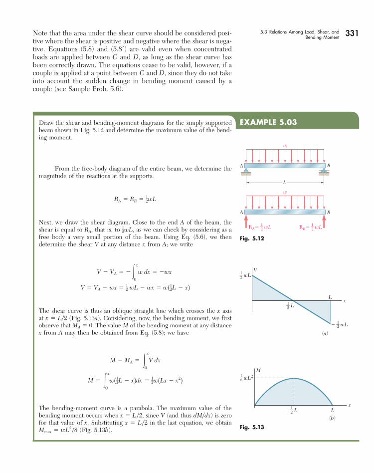
EXAMPLE 5.03Draw the shear and bending-moment diagrams for the simply supported beam shown in Fig. 5.12 and determine the maximum value of the bend-ing moment.
From the free-body diagram of the entire beam, we determine the magnitude of the reactions at the supports.
RA 5 RB 5 12wL
Next, we draw the shear diagram. Close to the end A of the beam, the shear is equal to RA, that is, to 1
2wL, as we can check by considering as a free body a very small portion of the beam. Using Eq. (5.6), we then determine the shear V at any distance x from A; we write
V 2 VA 5 2#x
0
w dx 5 2wx
V 5 VA 2 wx 5 12 wL 2 wx 5 w112L 2 x2
The shear curve is thus an oblique straight line which crosses the x axis at x 5 Ly2 (Fig. 5.13a). Considering, now, the bending moment, we first observe that MA 5 0. The value M of the bending moment at any distance x from A may then be obtained from Eq. (5.8); we have
M 2 MA 5 #x
0
V dx
M 5 #x
0
w112L 2 x2dx 5 12w1Lx 2 x22
The bending-moment curve is a parabola. The maximum value of the bending moment occurs when x 5 Ly2, since V (and thus dMydx) is zero for that value of x. Substituting x 5 Ly2 in the last equation, we obtain Mmax 5 wL2y8 (Fig. 5.13b).
� wL12
wL12
L12
x
V
(a)
L
wL218
L L12
M
(b)
x
Fig. 5.13
bee80288_ch05_314-379.indd Page 331 10/27/10 9:53:04 PM user-f499bee80288_ch05_314-379.indd Page 331 10/27/10 9:53:04 PM user-f499 /Volumes/201/MHDQ251/bee80288_disk1of1/0073380288/bee80288_pagefiles/Volumes/201/MHDQ251/bee80288_disk1of1/0073380288/bee80288_pagefiles

332 Analysis and Design of Beams for Bending In most engineering applications, one needs to know the value of the bending moment only at a few specific points. Once the shear diagram has been drawn, and after M has been determined at one of the ends of the beam, the value of the bending moment can then be obtained at any given point by computing the area under the shear curve and using Eq. (5.89). For instance, since MA 5 0 for the beam of Example 5.03, the maximum value of the bending moment for that beam can be obtained simply by measur-ing the area of the shaded triangle in the shear diagram of Fig. 5.13a. We have
Mmax 512
L2
wL2
5wL2
8
� wL12
wL12
L12
x
V
(a)
L
wL218
L L12
M
(b)
x
Fig. 5.13
We note that, in this example, the load curve is a horizontal straight line, the shear curve an oblique straight line, and the bending-moment curve a parabola. If the load curve had been an oblique straight line (first degree), the shear curve would have been a parabola (second degree) and the bending-moment curve a cubic (third degree). The shear and bending-moment curves will always be, respectively, one and two degrees higher than the load curve. With this in mind, we should be able to sketch the shear and bending-moment diagrams without actually determining the functions V(x) and M(x), once a few values of the shear and bending moment have been computed. The sketches obtained will be more accurate if we make use of the fact that, at any point where the curves are continu-ous, the slope of the shear curve is equal to 2w and the slope of the bending-moment curve is equal to V.
bee80288_ch05_314-379.indd Page 332 10/29/10 7:07:46 PM user-f499bee80288_ch05_314-379.indd Page 332 10/29/10 7:07:46 PM user-f499 /Volumes/201/MHDQ251/bee80288_disk1of1/0073380288/bee80288_pagefiles/Volumes/201/MHDQ251/bee80288_disk1of1/0073380288/bee80288_pagefiles

333
SAMPLE PROBLEM 5.3
Draw the shear and bending-moment diagrams for the beam and loading shown.EA
B C
6 ft
20 kips 12 kips 1.5 kips/ft
8 ft 8 ft10 ft
D
SOLUTION
Reactions. Considering the entire beam as a free body, we write
1l oMA 5 0:D124 ft2 2 120 kips2 16 ft2 2 112 kips2 114 ft2 2 112 kips2 128 ft2 5 0
D 5 126 kips D 5 26 kips x
1x oFy 5 0: Ay 2 20 kips 2 12 kips 1 26 kips 2 12 kips 5 0 Ay 5 118 kips A y 5 18 kips x
y1 oFx 5 0: Ax 5 0 A x 5 0
We also note that at both A and E the bending moment is zero; thus, two points (indicated by dots) are obtained on the bending-moment diagram.
Shear Diagram. Since dVydx 5 2w, we find that between concentrated loads and reactions the slope of the shear diagram is zero (i.e., the shear is constant). The shear at any point is determined by dividing the beam into two parts and considering either part as a free body. For example, using the portion of beam to the left of section 1, we obtain the shear between B and C:
1xoFy 5 0: 118 kips 2 20 kips 2 V 5 0 V 5 22 kips
We also find that the shear is 112 kips just to the right of D and zero at end E. Since the slope dVydx 5 2w is constant between D and E, the shear diagram between these two points is a straight line.
Bending-Moment Diagram. We recall that the area under the shear curve between two points is equal to the change in bending moment between the same two points. For convenience, the area of each portion of the shear diagram is computed and is indicated in parentheses on the diagram. Since the bending moment MA at the left end is known to be zero, we write
MB 2 MA 5 1108 MB 5 1108 kip ? ft MC 2 MB 5 216 MC 5 192 kip ? ft MD 2 MC 5 2140 MD 5 248 kip ? ft ME 2 MD 5 148 ME 5 0
Since ME is known to be zero, a check of the computations is obtained. Between the concentrated loads and reactions, the shear is constant; thus, the slope dMydx is constant, and the bending-moment diagram is drawn by connecting the known points with straight lines. Between D and E where the shear diagram is an oblique straight line, the bending-moment diagram is a parabola. From the V and M diagrams we note that Vmax 5 18 kips and Mmax 5 108 kip ? ft.
E
E
A
A
Ax
Ay
B C
6 ft
4 ft
20 kips 12 kips
20 kips
20 kips
12 kips
26 kips18 kips
18 kips
V (kips)
M (kip ? ft)
x
x
�18(�108)
�108
�92
�48
(�48)
(�140)
�12
(�16)
�2
�14
15 kips/ft
12 kips
8 ft 8 ft10 ft
D
B 1 C D
D
M
V
bee80288_ch05_314-379.indd Page 333 11/12/10 7:31:15 PM user-f499bee80288_ch05_314-379.indd Page 333 11/12/10 7:31:15 PM user-f499 /Users/user-f499/Desktop/Temp Work/Don't Delete Job/MHDQ251:Beer:201/ch05/Users/user-f499/Desktop/Temp Work/Don't Delete Job/MHDQ251:Beer:201/ch05

334
SAMPLE PROBLEM 5.4
The W360 3 79 rolled-steel beam AC is simply supported and carries the uniformly distributed load shown. Draw the shear and bending-moment diagrams for the beam and determine the location and magnitude of the maximum normal stress due to bending.
SOLUTION
Reactions. Considering the entire beam as a free body, we find
RA 5 80 kN x RC 5 40 kN x
Shear Diagram. The shear just to the right of A is VA 5 180 kN. Since the change in shear between two points is equal to minus the area under the load curve between the same two points, we obtain VB by writing
VB 2 VA 5 2120 kN/m2 16 m2 5 2120 kN VB 5 2120 1 VA 5 2120 1 80 5 240 kN
The slope dVydx 5 2w being constant between A and B, the shear diagram between these two points is represented by a straight line. Between B and C, the area under the load curve is zero; therefore,
VC 2 VB 5 0 VC 5 VB 5 240 kN
and the shear is constant between B and C.
Bending-Moment Diagram. We note that the bending moment at each end of the beam is zero. In order to determine the maximum bending moment, we locate the section D of the beam where V 5 0. We write
VD 2 VA 5 2wx0 2 80 kN 5 2120 kN/m2 x
and, solving for x we find: x 5 4 m ◀
The maximum bending moment occurs at point D, where we have dMydx 5 V 5 0. The areas of the various portions of the shear diagram are computed and are given (in parentheses) on the diagram. Since the area of the shear diagram between two points is equal to the change in bending moment between the same two points, we write
MD 2 MA 5 1 160 kN ? m MD 5 1160 kN ? m MB 2 MD 5 2 40 kN ? m MB 5 1120 kN ? m MC 2 MB 5 2 120 kN ? m MC 5 0
The bending-moment diagram consists of an arc of parabola followed by a segment of straight line; the slope of the parabola at A is equal to the value of V at that point.
Maximum Normal Stress. It occurs at D, where |M| is largest. From Appendix C we find that for a W360 3 79 rolled-steel shape, S 5 1270 mm3 about a horizontal axis. Substituting this value and |M| 5 |MD| 5 160 3 103 N ? m into Eq. (5.3), we write
sm 50MD 0
S5
160 3 103 N ? m1270 3 1026 m3 5 126.0 3 106 Pa
Maximum normal stress in the beam 5 126.0 MPa b
CB
A
20 kN/m
6 m 3 m
C
C
B
w
A
V
D B
b
a
A
20 kN/m
80 kN
80 kN
(�160)
(�120)
40 kN
�40 kN(�40)
6 m
x � 4m160 kN ? m
120 kN ? m
x
M
A
x
x
bee80288_ch05_314-379.indd Page 334 11/12/10 7:31:22 PM user-f499bee80288_ch05_314-379.indd Page 334 11/12/10 7:31:22 PM user-f499 /Users/user-f499/Desktop/Temp Work/Don't Delete Job/MHDQ251:Beer:201/ch05/Users/user-f499/Desktop/Temp Work/Don't Delete Job/MHDQ251:Beer:201/ch05

335
SAMPLE PROBLEM 5.5
Sketch the shear and bending-moment diagrams for the cantilever beam shown.
SOLUTION
Shear Diagram. At the free end of the beam, we find VA 5 0. Between A and B, the area under the load curve is 1
2 w0 a; we find VB by writing
VB 2 VA 5 212 w0
a VB 5 212 w0
a
Between B and C, the beam is not loaded; thus VC 5 VB. At A, we have w 5 w0 and, according to Eq. (5.5), the slope of the shear curve is dVydx 5 2w0, while at B the slope is dVydx 5 0. Between A and B, the loading decreases linearly, and the shear diagram is parabolic. Between B and C, w 5 0, and the shear diagram is a horizontal line.
Bending-Moment Diagram. The bending moment MA at the free end of the beam is zero. We compute the area under the shear curve and write
MB 2 MA 5 213 w0
a2 MB 5 213 w0
a2
MC 2 MB 5 212 w0
a1L 2 a2 MC 5 21
6 w0 a13L 2 a2
The sketch of the bending-moment diagram is completed by recalling that dMydx 5 V. We find that between A and B the diagram is represented by a cubic curve with zero slope at A, and between B and C by a straight line.
CB
w0
A
V
M
a
L
� w0a213 � w0a(L � a)1
2
� w0a12
� w0a213
� w0a(3L � a)16
� w0a
x
x
12
SAMPLE PROBLEM 5.6
The simple beam AC is loaded by a couple of moment T applied at point B. Draw the shear and bending-moment diagrams of the beam.
SOLUTION
The entire beam is taken as a free body, and we obtain
RA 5TLx RC 5
TLw
The shear at any section is constant and equal to TyL. Since a couple is applied at B, the bending-moment diagram is discontinuous at B; it is rep-resented by two oblique straight lines and decreases suddenly at B by an amount equal to T. The character of this discontinuity can also be verified by equilibrium analysis. For example, considering the free body of the por-tion of the beam from A to just beyond the right of B as shown, we find the value of M by
1l©MB 5 0: 2 TL
a 1 T 1 M 5 0 M 5 2T a1 2aLb
CB
A
V
M
B
L
x
x
Ta
TL
�T(1 � )aL
T aL
T V M
RA� T�L
bee80288_ch05_314-379.indd Page 335 11/16/10 6:42:19 PM user-f499bee80288_ch05_314-379.indd Page 335 11/16/10 6:42:19 PM user-f499 /Volumes/201/MHDQ251/bee80288_disk1of1/0073380288/bee80288_pagefiles/Volumes/201/MHDQ251/bee80288_disk1of1/0073380288/bee80288_pagefiles

PROBLEMS
336
5.34 Using the method of Sec. 5.3, solve Prob. 5.1a.
5.35 Using the method of Sec. 5.3, solve Prob. 5.2a.
5.36 Using the method of Sec. 5.3, solve Prob. 5.3a.
5.37 Using the method of Sec. 5.3, solve Prob. 5.4a.
5.38 Using the method of Sec. 5.3, solve Prob. 5.5a.
5.39 Using the method of Sec. 5.3, solve Prob. 5.6a.
5.40 Using the method of Sec. 5.3, solve Prob. 5.7.
5.41 Using the method of Sec. 5.3, solve Prob. 5.8.
5.42 Using the method of Sec. 5.3, solve Prob. 5.9.
5.43 Using the method of Sec. 5.3, solve Prob. 5.10.
5.44 and 5.45 Draw the shear and bending-moment diagrams for the beam and loading shown, and determine the maximum abso-lute value (a) of the shear, (b) of the bending moment.
Fig. P5.44
A
1.5 m 0.9 m
3 kN
3.5 kN/m
0.6 m
ED
CB
0.5 m
4 kN
1 m 1 m0.5 m
4 kN
A
E
DCB
F
Fig. P5.45
5.46 Using the method of Sec. 5.3, solve Prob. 5.15.
5.47 Using the method of Sec. 5.3, solve Prob. 5.16.
5.48 Using the method of Sec. 5.3, solve Prob. 5.18.
5.49 Using the method of Sec. 5.3, solve Prob. 5.19.
5.50 For the beam and loading shown, determine the equations of the shear and bending-moment curves and the maximum absolute value of the bending moment in the beam, knowing that (a) k 5 1, (b) k 5 0.5.
x
w
w0
– kw0L
Fig. P5.50
bee80288_ch05_314-379.indd Page 336 10/27/10 9:53:25 PM user-f499bee80288_ch05_314-379.indd Page 336 10/27/10 9:53:25 PM user-f499 /Volumes/201/MHDQ251/bee80288_disk1of1/0073380288/bee80288_pagefiles/Volumes/201/MHDQ251/bee80288_disk1of1/0073380288/bee80288_pagefiles

337 5.51 and 5.52 Determine (a) the equations of the shear and bending-moment curves for the beam and loading shown, (b) the maximum absolute value of the bending moment in the beam.
Bx
ww � w0
A
L
xL
Fig. P5.51
Bx
w w � w0 sin
A
L
� xL
Fig. P5.52
5.53 Determine (a) the equations of the shear and bending-moment curves for the beam and loading shown, (b) the maximum absolute value of the bending moment in the beam.
w
A
L
Bx
w � w0 cos� x2L
Fig. P5.53
C DA B
6 ft 6 ft2 ft
2 kips/ft6 kips
W8 � 31
Fig. P5.54
CA B
1 m4 m 160 mm
140 mm3 kN/m
2 kN
Fig. P5.55
5.56 and 5.57 Draw the shear and bending-moment diagrams for the beam and loading shown and determine the maximum normal stress due to bending.
A B
80 lb /ft
1600 lb
1.5 ft
9 ft
11.5 in.
1.5 in.
Fig. P5.56
BDC
250 kN 150 kN
A
2 m 2 m 2 m
W410 � 114
Fig. P5.57
5.54 and 5.55 Draw the shear and bending-moment diagrams for the beam and loading shown and determine the maximum normal stress due to bending.
Problems
bee80288_ch05_314-379.indd Page 337 10/27/10 9:53:33 PM user-f499bee80288_ch05_314-379.indd Page 337 10/27/10 9:53:33 PM user-f499 /Volumes/201/MHDQ251/bee80288_disk1of1/0073380288/bee80288_pagefiles/Volumes/201/MHDQ251/bee80288_disk1of1/0073380288/bee80288_pagefiles

338 Analysis and Design of Beams for Bending 5.58 and 5.59 Draw the shear and bending-moment diagrams for the beam and loading shown and determine the maximum normal stress due to bending.
A BDC
80 kN/m
W250 � 80
1.2 m 1.2 m1.6 m
60 kN · m 12 kN · m
B
CA
8 in.20 in.
3 in.
800 lb/in.
2 in.12
1 in.14
Fig. P5.59Fig. P5.58
5.60 Beam AB, of length L and square cross section of side a, is sup-ported by a pivot at C and loaded as shown. (a) Check that the beam is in equilibrium. (b) Show that the maximum stress due to bending occurs at C and is equal to w0L
2y(1.5a)3.
B
a
aA
2L3
C
w0
L3
Fig. P5.60
A C BD
400 kN/m
W200 � 22.5w0
0.3 m 0.3 m0.4 m
Fig. P5.61
A
480 lb/ft
1 ft 1 ft
1.5 ft 1.5 ft
W8 � 31
8 ft
P
BC D E F
Q
Fig. P5.62
5.61 Knowing that beam AB is in equilibrium under the loading shown, draw the shear and bending-moment diagrams and determine the maximum normal stress due to bending.
*5.62 The beam AB supports a uniformly distributed load of 480 lb/ft and two concentrated loads P and Q. The normal stress due to bending on the bottom edge of the lower flange is 114.85 ksi at D and 110.65 ksi at E. (a) Draw the shear and bending-moment diagrams for the beam. (b) Determine the maximum normal stress due to bending that occurs in the beam.
bee80288_ch05_314-379.indd Page 338 10/27/10 9:53:49 PM user-f499bee80288_ch05_314-379.indd Page 338 10/27/10 9:53:49 PM user-f499 /Volumes/201/MHDQ251/bee80288_disk1of1/0073380288/bee80288_pagefiles/Volumes/201/MHDQ251/bee80288_disk1of1/0073380288/bee80288_pagefiles

*5.63 Beam AB supports a uniformly distributed load of 2 kN/m and two concentrated loads P and Q. It has been experimentally deter-mined that the normal stress due to bending in the bottom edge of the beam is 256.9 MPa at A and 229.9 MPa at C. Draw the shear and bending-moment diagrams for the beam and determine the magnitudes of the loads P and Q.
*5.64 The beam AB supports two concentrated loads P and Q. The normal stress due to bending on the bottom edge of the beam is 155 MPa at D and 137.5 MPa at F. (a) Draw the shear and bending-moment diagrams for the beam. (b) Determine the maxi-mum normal stress due to bending that occurs in the beam.
C D BA
2 kN/m
P
0.1 m 0.1 m 0.125 m
36 mm
18 mmQ
Fig. P5.63
Fig. P5.64
0.4 m
P Q 24 mm
0.2 m0.5 m 0.5 m
60 mmAC D E F
B
0.3 m
5.4 DESIGN OF PRISMATIC BEAMS FOR BENDINGAs indicated in Sec. 5.1, the design of a beam is usually controlled by the maximum absolute value |M|max of the bending moment that will occur in the beam. The largest normal stress sm in the beam is found at the surface of the beam in the critical section where |M|max occurs and can be obtained by substituting |M|max for |M| in Eq. (5.1) or Eq. (5.3).† We write
sm 5
ZMZmaxc
I sm 5
ZMZmax
S (5.19, 5.39)
A safe design requires that sm # sall, where sall is the allowable stress for the material used. Substituting sall for sm in (5.39) and solving for S yields the minimum allowable value of the section modulus for the beam being designed:
Smin 5
ZMZmax
sall (5.9)
The design of common types of beams, such as timber beams of rectangular cross section and rolled-steel beams of various cross-sectional shapes, will be considered in this section. A proper proce-dure should lead to the most economical design. This means that, among beams of the same type and the same material, and other
†For beams that are not symmetrical with respect to their neutral surface, the largest of the distances from the neutral surface to the surfaces of the beam should be used for c in Eq. (5.1) and in the computation of the section modulus S 5 I/c.
5.4 Design of Prismatic Beams for Bending 339
bee80288_ch05_314-379.indd Page 339 10/27/10 9:53:54 PM user-f499bee80288_ch05_314-379.indd Page 339 10/27/10 9:53:54 PM user-f499 /Volumes/201/MHDQ251/bee80288_disk1of1/0073380288/bee80288_pagefiles/Volumes/201/MHDQ251/bee80288_disk1of1/0073380288/bee80288_pagefiles

340 Analysis and Design of Beams for Bending things being equal, the beam with the smallest weight per unit length—and, thus, the smallest cross-sectional area—should be selected, since this beam will be the least expensive. The design procedure will include the following steps†:
1. First determine the value of sall for the material selected from a table of properties of materials or from design specifications. You can also compute this value by dividing the ultimate strength sU of the material by an appropriate factor of safety (Sec. 1.13). Assuming for the time being that the value of sall is the same in tension and in compression, proceed as follows.
2. Draw the shear and bending-moment diagrams corresponding to the specified loading conditions, and determine the maximum absolute value |M|max of the bending moment in the beam.
3. Determine from Eq. (5.9) the minimum allowable value Smin of the section modulus of the beam.
4. For a timber beam, the depth h of the beam, its width b, or the ratio hyb characterizing the shape of its cross section will probably have been specified. The unknown dimensions may then be selected by recalling from Eq. (4.19) of Sec. 4.4 that b and h must satisfy the relation 1
6 bh2 5 S $ Smin.
5. For a rolled-steel beam, consult the appropriate table in Appen-dix C. Of the available beam sections, consider only those with a section modulus S $ Smin and select from this group the section with the smallest weight per unit length. This is the most eco-nomical of the sections for which S $ Smin. Note that this is not necessarily the section with the smallest value of S (see Example 5.04). In some cases, the selection of a section may be limited by other considerations, such as the allowable depth of the cross section, or the allowable deflection of the beam (cf. Chap. 9).
The foregoing discussion was limited to materials for which sall is the same in tension and in compression. If sall is different in tension and in compression, you should make sure to select the beam section in such a way that sm # sall for both tensile and compressive stresses. If the cross section is not symmetric about its neutral axis, the largest tensile and the largest compressive stresses will not necessarily occur in the section where |M| is maximum. One may occur where M is maxi-mum and the other where M is minimum. Thus, step 2 should include the determination of both Mmax and Mmin, and step 3 should be modified to take into account both tensile and compressive stresses. Finally, keep in mind that the design procedure described in this section takes into account only the normal stresses occurring on the surface of the beam. Short beams, especially those made of tim-ber, may fail in shear under a transverse loading. The determination of shearing stresses in beams will be discussed in Chap. 6. Also, in the case of rolled-steel beams, normal stresses larger than those con-sidered here may occur at the junction of the web with the flanges. This will be discussed in Chap. 8.
†We assume that all beams considered in this chapter are adequately braced to prevent lateral buckling, and that bearing plates are provided under concentrated loads applied to rolled-steel beams to prevent local buckling (crippling) of the web.
bee80288_ch05_314-379.indd Page 340 10/27/10 9:54:00 PM user-f499bee80288_ch05_314-379.indd Page 340 10/27/10 9:54:00 PM user-f499 /Volumes/201/MHDQ251/bee80288_disk1of1/0073380288/bee80288_pagefiles/Volumes/201/MHDQ251/bee80288_disk1of1/0073380288/bee80288_pagefiles

*Load and Resistance Factor Design. This alternative method of design was briefly described in Sec. 1.13 and applied to mem-bers under axial loading. It can readily be applied to the design of beams in bending. Replacing in Eq. (1.26) the loads PD, PL, and PU, respectively, by the bending moments MD, ML, and MU, we write
gDMD 1 gLML # fMU (5.10)
The coefficients gD and gL are referred to as the load factors and the coefficient f as the resistance factor. The moments MD and ML are the bending moments due, respectively, to the dead and the live loads, while MU is equal to the product of the ultimate strength sU of the material and the section modulus S of the beam: MU 5 SsU.
EXAMPLE 5.04Select a wide-flange beam to support the 15-kip load as shown in Fig. 5.14. The allowable normal stress for the steel used is 24 ksi.
1. The allowable normal stress is given: sall 5 24 ksi. 2. The shear is constant and equal to 15 kips. The bending moment
is maximum at B. We have
ZMZmax 5 115 kips2 18 ft2 5 120 kip ? ft 5 1440 kip ? in.
3. The minimum allowable section modulus is
Smin 5ZMZmax
sall5
1440 kip ? in.
24 ksi5 60.0 in3
4. Referring to the table of Properties of Rolled-Steel Shapes in Appen-dix C, we note that the shapes are arranged in groups of the same depth and that in each group they are listed in order of decreasing weight. We choose in each group the lightest beam having a section modulus S 5 Iyc at least as large as Smin and record the results in the following table.
Shape S, in3
W21 3 44 81.6W18 3 50 88.9W16 3 40 64.7W14 3 43 62.6W12 3 50 64.2W10 3 54 60.0
The most economical is the W16 3 40 shape since it weighs only 40 lb/ft, even though it has a larger section modulus than two of the other shapes. We also note that the total weight of the beam will be (8 ft) 3 (40 lb) 5 320 lb. This weight is small compared to the 15,000-1b load and can be neglected in our analysis.
15 kips8 ft
A B
Fig. 5.14
341
bee80288_ch05_314-379.indd Page 341 10/27/10 9:54:00 PM user-f499bee80288_ch05_314-379.indd Page 341 10/27/10 9:54:00 PM user-f499 /Volumes/201/MHDQ251/bee80288_disk1of1/0073380288/bee80288_pagefiles/Volumes/201/MHDQ251/bee80288_disk1of1/0073380288/bee80288_pagefiles

342
SAMPLE PROBLEM 5.7
A 12-ft-long overhanging timber beam AC with an 8-ft span AB is to be designed to support the distributed and concentrated loads shown. Knowing that timber of 4-in. nominal width (3.5-in. actual width) with a 1.75-ksi allowable stress is to be used, determine the minimum required depth h of the beam.
BA C h
8 ft 4 ft
3.5 in.400 lb/ft 4.5 kips
SOLUTION
Reactions. Considering the entire beam as a free body, we write
1l oMA 5 0: B 18 ft2 2 13.2 kips2 14 ft2 2 14.5 kips2 112 ft2 5 0 B 5 8.35 kips B 5 8.35 kipsx
1y
oFx 5 0: Ax 5 0
1xoFy 5 0: Ay 1 8.35 kips 2 3.2 kips 2 4.5 kips 5 0 Ay 5 20.65 kips A 5 0.65 kips w
Shear Diagram. The shear just to the right of A is VA 5 Ay 5 20.65 kips. Since the change in shear between A and B is equal to minus the area under the load curve between these two points, we obtain VB by writing
VB 2 VA 5 2 1400 lb/ft2 18 ft2 5 23200 lb 5 23.20 kips VB 5 VA 2 3.20 kips 5 20.65 kips 2 3.20 kips 5 23.85 kips.
The reaction at B produces a sudden increase of 8.35 kips in V, resulting in a value of the shear equal to 4.50 kips to the right of B. Since no load is applied between B and C, the shear remains constant between these two points.
Determination of |M|max. We first observe that the bending moment is equal to zero at both ends of the beam: MA 5 MC 5 0. Between A and B the bending moment decreases by an amount equal to the area under the shear curve, and between B and C it increases by a corresponding amount. Thus, the maximum absolute value of the bending moment is |M|max 5 18.00 kip ? ft.
Minimum Allowable Section Modulus. Substituting into Eq. (5.9) the given value of sall and the value of |M|max that we have found, we write
Smin 50M 0max
sall5118 kip ? ft2 112 in./ft2
1.75 ksi5 123.43 in3
Minimum Required Depth of Beam. Recalling the formula developed in part 4 of the design procedure described in Sec. 5.4 and substituting the values of b and Smin, we have
16 bh2 $ Smin 1
6 13.5 in.2h2 $ 123.43 in3 h $ 14.546 in.
The minimum required depth of the beam is h 5 14.55 in. ◀
Note: In practice, standard wood shapes are specified by nominal dimensions that are slightly larger than actual. In this case, we would specify a 4-in. 3 16-in. member, whose actual dimensions are 3.5 in. 3 15.25 in.
BA
V
A
AxAy
B
C
8 ft 4 ft
3.2 kips4.5 kips
(�18)
(�18)
4.50kips
�3.85 kips
�0.65kips
CB x
bee80288_ch05_314-379.indd Page 342 11/16/10 6:42:31 PM user-f499bee80288_ch05_314-379.indd Page 342 11/16/10 6:42:31 PM user-f499 /Volumes/201/MHDQ251/bee80288_disk1of1/0073380288/bee80288_pagefiles/Volumes/201/MHDQ251/bee80288_disk1of1/0073380288/bee80288_pagefiles

343
SAMPLE PROBLEM 5.8
A 5-m-long, simply supported steel beam AD is to carry the distributed and concentrated loads shown. Knowing that the allowable normal stress for the grade of steel to be used is 160 MPa, select the wide-flange shape that should be used.
SOLUTION
Reactions. Considering the entire beam as a free body, we write
1loMA 5 0: D 15 m 2 2 160 kN 2 11.5 m 2 2 150 kN 2 14 m 2 5 0D 5 58.0 kN D 5 58.0 kNx
1y
oFx 5 0: Ax 5 0
1xoFy 5 0: Ay 1 58.0 kN 2 60 kN 2 50 kN 5 0Ay 5 52.0 kN A 5 52.0 kNx
Shear Diagram. The shear just to the right of A is VA 5 Ay 5 152.0 kN. Since the change in shear between A and B is equal to minus the area under the load curve between these two points, we have
VB 5 52.0 kN 2 60 kN 5 28 kN
The shear remains constant between B and C, where it drops to 258 kN, and keeps this value between C and D. We locate the section E of the beam where V 5 0 by writing
VE 2 VA 5 2wx0 2 52.0 kN 5 2 120 kN/m 2 x
Solving for x we find x 5 2.60 m.
Determination of |M|max. The bending moment is maximum at E, where V 5 0. Since M is zero at the support A, its maximum value at E is equal to the area under the shear curve between A and E. We have, there-fore, |M|max 5 ME 5 67.6 kN ? m.
Minimum Allowable Section Modulus. Substituting into Eq. (5.9) the given value of sall and the value of |M|max that we have found, we write
Smin 50M 0max
sall5
67.6 kN ? m160 MPa
5 422.5 3 1026 m3 5 422.5 3 103 mm3
Selection of Wide-Flange Shape. From Appendix C we compile a list of shapes that have a section modulus larger than Smin and are also the lightest shape in a given depth group.
Shape S, mm3
W410 3 38.8 629W360 3 32.9 475W310 3 38.7 547W250 3 44.8 531W200 3 46.1 451
We select the lightest shape available, namely W360 3 32.9 b
CB D
1.5 m
52 kN
x � 2.6 m
�58 kN
�8 kN
(67.6)
1.5 m1 m 1 m
50 kN
D
A
V
AE B C D
x
AxAy
60 kN
B
A
C D
3 m1 m 1 m
20 kN50 kN
bee80288_ch05_314-379.indd Page 343 10/28/10 7:26:00 PM user-f499bee80288_ch05_314-379.indd Page 343 10/28/10 7:26:00 PM user-f499 /Volumes/201/MHDQ251/bee80288_disk1of1/0073380288/bee80288_pagefiles/Volumes/201/MHDQ251/bee80288_disk1of1/0073380288/bee80288_pagefiles

PROBLEMS
344
5.65 and 5.66 For the beam and loading shown, design the cross section of the beam, knowing that the grade of timber used has an allowable normal stress of 12 MPa.
5.67 and 5.68 For the beam and loading shown, design the cross section of the beam, knowing that the grade of timber used has an allowable normal stress of 1750 psi.
5.69 and 5.70 For the beam and loading shown, design the cross section of the beam, knowing that the grade of timber used has an allowable normal stress of 12 MPa.
1.8 kN 3.6 kN
CBA D h
0.8 m 0.8 m 0.8 m
40 mm
Fig. P5.65
A BC h
1.2 m 1.2 m
125 mm18 kN/m
Fig. P5.66
1.2 kips/ft
6 fta
aB
A
Fig. P5.68
CBA D h
3 ft 6 ft
5 in.1.5 kips/ft
3 ft
Fig. P5.67
AB
150 mm
b3 kN/m
C
2.4 m 1.2 m
Fig. P5.70
CA
BD h
0.6 m 0.6 m3 m
100 mm6 kN/m2.5 kN2.5 kN
Fig. P5.69
bee80288_ch05_314-379.indd Page 344 10/27/10 9:54:16 PM user-f499bee80288_ch05_314-379.indd Page 344 10/27/10 9:54:16 PM user-f499 /Volumes/201/MHDQ251/bee80288_disk1of1/0073380288/bee80288_pagefiles/Volumes/201/MHDQ251/bee80288_disk1of1/0073380288/bee80288_pagefiles

345ProblemsProblems 5.71 and 5.72 Knowing that the allowable stress for the steel used is 24 ksi, select the most economical wide-flange beam to support the loading shown.
Fig. P5.72
2.75 kips/ft
24 kips
BA C
9 ft 15 ft5 ft12 ft
5 ft
62 kips
62 kips
B C A D
Fig. P5.71
5.73 and 5.74 Knowing that the allowable stress for the steel used is 160 MPa, select the most economical wide-flange beam to sup-port the loading shown.
Fig. P5.73
6 kN/m
18 kN/m
6 m
AB
Fig. P5.74
5 kN/m
70 kN 70 kN
A DCB
3 m 3 m5 m
5.75 and 5.76 Knowing that the allowable stress for the steel used is 160 MPa, select the most economical S-shape beam to support the loading shown.
Fig. P5.75
CDA
B
2.5 m 2.5 m 5 m
60 kN 40 kN
Fig. P5.76
45 kN/m
A DCB
3 m 3 m9 m
70 kN 70 kN
5.77 and 5.78 Knowing that the allowable stress for the steel used is 24 ksi, select the most economical S-shape beam to support the loading shown.
48 kips 48 kips 48 kips
AD
ECB
6 ft2 ft2 ft2 ft
Fig. P5.77
3 kips/ft
18 kips
ADCB
6 ft 6 ft3 ft
Fig. P5.78
bee80288_ch05_314-379.indd Page 345 10/27/10 9:54:31 PM user-f499bee80288_ch05_314-379.indd Page 345 10/27/10 9:54:31 PM user-f499 /Volumes/201/MHDQ251/bee80288_disk1of1/0073380288/bee80288_pagefiles/Volumes/201/MHDQ251/bee80288_disk1of1/0073380288/bee80288_pagefiles

346 Analysis and Design of Beams for Bending 5.79 Two L102 3 76 rolled-steel angles are bolted together and used to support the loading shown. Knowing that the allowable normal stress for the steel used is 140 MPa, determine the minimum angle thickness that can be used.
B
4.5 kN/m
9 kN
A C
1 m1 m
152 mm
102 mm
Fig. P5.79
5.80 Two rolled-steel channels are to be welded back to back and used to support the loading shown. Knowing that the allowable normal stress for the steel used is 30 ksi, determine the most economical channels that can be used.
5.81 Three steel plates are welded together to form the beam shown. Knowing that the allowable normal stress for the steel used is 22 ksi, determine the minimum flange width b that can be used.
B
2.25 kips/ft
20 kips
AC
D
12 ft3 ft
6 ft
Fig. P5.80 8 kips 32 kips 32 kips
B DA
CE
b
4.5 ft14 ft 14 ft
9.5 ft
in.
1 in.
1 in.
19 in.34
Fig. P5.81
5.82 A steel pipe of 100-mm diameter is to support the loading shown. Knowing that the stock of pipes available has thicknesses varying from 6 mm to 24 mm in 3-mm increments, and that the allowable normal stress for the steel used is 150 MPa, determine the mini-mum wall thickness t that can be used.
5.83 Assuming the upward reaction of the ground to be uniformly dis-tributed and knowing that the allowable normal stress for the steel used is 24 ksi, select the most economical wide-flange beam to support the loading shown.
A B C D
100 mm
t
1.5 kN 1.5 kN
1 m0.5 m 0.5 m
1.5 kN
Fig. P5.82
B C
200 kips 200 kips
A DD
4 ft4 ft 4 ft
Fig. P5.83B C
Total load � 2 MN
A D
0.75 m 0.75 m1 m
D
Fig. P5.84
5.84 Assuming the upward reaction of the ground to be uniformly dis-tributed and knowing that the allowable normal stress for the steel used is 170 MPa, select the most economical wide-flange beam to support the loading shown.
bee80288_ch05_314-379.indd Page 346 10/27/10 9:54:49 PM user-f499bee80288_ch05_314-379.indd Page 346 10/27/10 9:54:49 PM user-f499 /Volumes/201/MHDQ251/bee80288_disk1of1/0073380288/bee80288_pagefiles/Volumes/201/MHDQ251/bee80288_disk1of1/0073380288/bee80288_pagefiles

347Problems 5.85 and 5.86 Determine the largest permissible value of P for the beam and loading shown, knowing that the allowable normal stress is 16 ksi in tension and 218 ksi in compression.
B
CA D
10 in. 6 in.20 in. 0.5 in.
0.5 in.2 in.
4 in.P P
B CA D
16 in. 8 in. 4 in.
2 in.0.5 in.
0.5 in.
8 in.
P P
Fig. P5.86Fig. P5.85
5.87 Determine the largest permissible distributed load w for the beam shown, knowing that the allowable normal stress is 180 MPa in tension and 2130 MPa in compression.
B C
w
A D
0.2 m 0.2 m0.5 m
20 mm
20 mm
60 mm
60 mm
Fig. P5.87
5.88 Solve Prob. 5.87, assuming that the cross section of the beam is reversed, with the flange of the beam resting on the supports at B and C.
5.89 A 54-kip load is to be supported at the center of the 16-ft span shown. Knowing that the allowable normal stress for the steel used is 24 ksi, determine (a) the smallest allowable length l of beam CD if the W12 3 50 beam AB is not to be overstressed, (b) the most economical W shape that can be used for beam CD. Neglect the weight of both beams.
5.90 A uniformly distributed load of 66 kN/m is to be supported over the 6-m span shown. Knowing that the allowable normal stress for the steel used is 140 MPa, determine (a) the smallest allowable length l of beam CD if the W460 3 74 beam AB is not to be overstressed, (b) the most economical W shape that can be used for beam CD. Neglect the weight of both beams.
BA
C D
l/2 l/2
L �16 ft
W12 � 50
54 kips
Fig. P5.89
BAC D
W460 � 74
66 kN/m 66 kN/m
l
L � 6 m
Fig. P5.90
bee80288_ch05_314-379.indd Page 347 10/27/10 9:55:03 PM user-f499bee80288_ch05_314-379.indd Page 347 10/27/10 9:55:03 PM user-f499 /Volumes/201/MHDQ251/bee80288_disk1of1/0073380288/bee80288_pagefiles/Volumes/201/MHDQ251/bee80288_disk1of1/0073380288/bee80288_pagefiles

348 Analysis and Design of Beams for Bending 5.91 Each of the three rolled-steel beams shown (numbered 1, 2, and 3) is to carry a 64-kip load uniformly distributed over the beam. Each of these beams has a 12-ft span and is to be supported by the two 24-ft rolled-steel girders AC and BD. Knowing that the allowable normal stress for the steel used is 24 ksi, select (a) the most economical S shape for the three beams, (b) the most eco-nomical W shape for the two girders.
4 ft
4 ft
12 ft
8 ft
1
2
3
8 ft
B
A
C
D
Fig. P5.91
5.92 Beams AB, BC, and CD have the cross section shown and are pin-connected at B and C. Knowing that the allowable normal stress is 1110 MPa in tension and 2150 MPa in compression, determine (a) the largest permissible value of w if beam BC is not to be overstressed, (b) the corresponding maximum distance a for which the cantilever beams AB and CD are not overstressed.
B C
w
D
a 7.2 m
12.5 mm
12.5 mm
150 mm
200 mm
A
a
Fig. P5.92
bee80288_ch05_314-379.indd Page 348 10/27/10 9:55:10 PM user-f499bee80288_ch05_314-379.indd Page 348 10/27/10 9:55:10 PM user-f499 /Volumes/201/MHDQ251/bee80288_disk1of1/0073380288/bee80288_pagefiles/Volumes/201/MHDQ251/bee80288_disk1of1/0073380288/bee80288_pagefiles

349Problems 5.93 Beams AB, BC, and CD have the cross section shown and are pin-connected at B and C. Knowing that the allowable normal stress is 1110 MPa in tension and 2150 MPa in compression, determine (a) the largest permissible value of P if beam BC is not to be overstressed, (b) the corresponding maximum distance a for which the cantilever beams AB and CD are not overstressed.
PP
B C D
a2.4 m 2.4 m 2.4 m
12.5 mm
12.5 mm
150 mm
200 mm
A
a
Fig. P5.93
a
A B
x
L
P2P1
Fig. P5.94
*5.94 A bridge of length L 5 48 ft is to be built on a secondary road whose access to trucks is limited to two-axle vehicles of medium weight. It will consist of a concrete slab and of simply supported steel beams with an ultimate strength sU 5 60 ksi. The combined weight of the slab and beams can be approximated by a uniformly distributed load w 5 0.75 kips/ft on each beam. For the purpose of the design, it is assumed that a truck with axles located at a distance a 5 14 ft from each other will be driven across the bridge and that the resulting concentrated loads P1 and P2 exerted on each beam could be as large as 24 kips and 6 kips, respectively. Determine the most economical wide-flange shape for the beams, using LRFD with the load factors gD 5 1.25, gL 5 1.75 and the resistance factor f 5 0.9. [Hint: It can be shown that the maxi-mum value of |ML| occurs under the larger load when that load is located to the left of the center of the beam at a distance equal to aP2y2(P1 1 P2).]
*5.95 Assuming that the front and rear axle loads remain in the same ratio as for the truck of Prob. 5.94, determine how much heavier a truck could safely cross the bridge designed in that problem.
*5.96 A roof structure consists of plywood and roofing material sup-ported by several timber beams of length L 5 16 m. The dead load carried by each beam, including the estimated weight of the beam, can be represented by a uniformly distributed load wD 5 350 N/m. The live load consists of a snow load, represented by a uniformly distributed load wL 5 600 N/m, and a 6-kN concen-trated load P applied at the midpoint C of each beam. Knowing that the ultimate strength for the timber used is sU 5 50 MPa and that the width of each beam is b 5 75 mm, determine the mini-mum allowable depth h of the beams, using LRFD with the load factors gD 5 1.2, gL 5 1.6 and the resistance factor f 5 0.9.
*5.97 Solve Prob. 5.96, assuming that the 6-kN concentrated load P applied to each beam is replaced by 3-kN concentrated loads P1 and P2 applied at a distance of 4 m from each end of the beams.
P
wD � wL
C
b
hA B
L12 L1
2
Fig. P5.96
bee80288_ch05_314-379.indd Page 349 10/27/10 9:55:15 PM user-f499bee80288_ch05_314-379.indd Page 349 10/27/10 9:55:15 PM user-f499 /Volumes/201/MHDQ251/bee80288_disk1of1/0073380288/bee80288_pagefiles/Volumes/201/MHDQ251/bee80288_disk1of1/0073380288/bee80288_pagefiles

350 Analysis and Design of Beams for Bending *5.5 USING SINGULARITY FUNCTIONS TO DETERMINE SHEAR AND BENDING MOMENT IN A BEAM
Reviewing the work done in the preceding sections, we note that the shear and bending moment could only rarely be described by single analytical functions. In the case of the cantilever beam of Example 5.02 (Fig. 5.9), which supported a uniformly distributed load w, the shear and bending moment could be represented by single analytical functions, namely, V 5 2wx and M 5 21
2wx2; this was due to the fact that no discontinuity existed in the loading of the beam. On the other hand, in the case of the simply supported beam of Exam-ple 5.01, which was loaded only at its midpoint C, the load P applied at C represented a singularity in the beam loading. This singularity resulted in discontinuities in the shear and bending moment and required the use of different analytical functions to represent V and M in the portions of beam located, respectively, to the left and to the right of point C. In Sample Prob. 5.2, the beam had to be divided into three portions, in each of which different functions were used to represent the shear and the bending moment. This situation led us to rely on the graphical representation of the functions V and M provided by the shear and bending-moment diagrams and, later in Sec. 5.3, on a graphical method of integration to determine V and M from the distributed load w. The purpose of this section is to show how the use of singular-ity functions makes it possible to represent the shear V and the bending moment M by single mathematical expressions. Consider the simply supported beam AB, of length 2a, which carries a uniformly distributed load w0 extending from its midpoint C to its right-hand support B (Fig. 5.15). We first draw the free-body diagram of the entire beam (Fig. 5.16a); replacing the distributed load by an equivalent concentrated load and, summing moments about B, we write
1l oMB 5 0: 1w0a2 112a2 2 RA12a2 5 0 RA 5 14w0a
Next we cut the beam at a point D between A and C. From the free-body diagram of AD (Fig. 5.16b) we conclude that, over the interval 0 , x , a, the shear and bending moment are expressed, respectively, by the functions
V11x2 5 14w0a and M11x2 5 1
4w0ax
Cutting, now, the beam at a point E between C and B, we draw the free-body diagram of portion AE (Fig. 5.16c). Replacing the distrib-uted load by an equivalent concentrated load, we write
1x oFy 5 0: 14w0a 2 w01x 2 a2 2 V2 5 0
1l oME 5 0: 214w0ax 1 w01x 2 a2 3 12 1x 2 a2 4 1 M2 5 0
and conclude that, over the interval a , x , 2a, the shear and bend-ing moment are expressed, respectively, by the functions
V21x2 5 14w0a 2 w01x 2 a2 and M21x2 5 1
4w0ax 2 12w01x 2 a22
BC
w0
A
a a
Fig. 5.15
B
RB
M1
V1
RA
C
D
x
A
w0
w0 a
A
2a
a12
(a)
M2
V2
C
E
w0 (x � a)
A
x
a
(x � a)
x � a
12
(c)
(b)
RA� w0 a14
RA� w0 a14
Fig. 5.16
bee80288_ch05_314-379.indd Page 350 10/27/10 9:55:22 PM user-f499bee80288_ch05_314-379.indd Page 350 10/27/10 9:55:22 PM user-f499 /Volumes/201/MHDQ251/bee80288_disk1of1/0073380288/bee80288_pagefiles/Volumes/201/MHDQ251/bee80288_disk1of1/0073380288/bee80288_pagefiles

351 As we pointed out earlier in this section, the fact that the shear and bending moment are represented by different functions of x, depending upon whether x is smaller or larger than a, is due to the discontinuity in the loading of the beam. However, the functions V1(x) and V2(x) can be represented by the single expression
V1x2 5 14w0a 2 w0Hx 2 aI (5.11)
if we specify that the second term should be included in our com-putations when x $ a and ignored when x , a. In other words, the brackets H I should be replaced by ordinary parentheses ( ) when x $ a and by zero when x , a. With the same convention, the bending moment can be represented at any point of the beam by the single expression
M1x2 5 14 w0ax 2 1
2 w0Hx 2 aI2 (5.12)
From the convention we have adopted, it follows that brackets H I can be differentiated or integrated as ordinary parentheses. Instead of calculating the bending moment from free-body diagrams, we could have used the method indicated in Sec. 5.3 and integrated the expression obtained for V(x):
M1x2 2 M102 5 #x
0
V1x2 dx 5 #x
0
14w0a dx 2 #
x
0
w0Hx 2 aI dx
After integration, and observing that M(0) 5 0, we obtain as before
M1x2 5 14 w0ax 2 1
2 w0Hx 2 aI2
Furthermore, using the same convention again, we note that the distributed load at any point of the beam can be expressed as
w1x2 5 w0Hx 2 aI0 (5.13)
Indeed, the brackets should be replaced by zero for x , a and by parentheses for x $ a; we thus check that w(x) 5 0 for x , a and, defining the zero power of any number as unity, that Hx 2 aI0 5 1x 2 a20 5 1 and w(x) 5 w0 for x $ a. From Sec. 5.3 we recall that the shear could have been obtained by integrating the function 2w(x). Observing that V 5 1
4w0a for x 5 0, we write
V1x2 2 V102 5 2#x
0
w1x2 dx 5 2#x
0
w0Hx 2 aI0 dx
V1x2 2 14w0a 5 2w0Hx 2 aI1
Solving for V(x) and dropping the exponent 1, we obtain again
V1x2 5 14w0a 2 w0Hx 2 aI
The expressions Hx 2 aI0, Hx 2 aI, Hx 2 aI2 are called singularity functions. By definition, we have, for n $ 0,
Hx 2 aIn 5 e 1x 2 a2n
0 when x $ awhen x , a
(5.14)
5.5 Using Singularity Functions to Determine Shear and Bending Moment in a Beam
bee80288_ch05_314-379.indd Page 351 10/27/10 9:55:23 PM user-f499bee80288_ch05_314-379.indd Page 351 10/27/10 9:55:23 PM user-f499 /Volumes/201/MHDQ251/bee80288_disk1of1/0073380288/bee80288_pagefiles/Volumes/201/MHDQ251/bee80288_disk1of1/0073380288/bee80288_pagefiles

352 Analysis and Design of Beams for Bending We also note that whenever the quantity between brackets is positive or zero, the brackets should be replaced by ordinary parentheses, and whenever that quantity is negative, the bracket itself is equal to zero.
0(a) n � 0
� x � a �0
a x 0(b) n � 1
� x � a �1
a x 0(c) n � 2
� x � a �2
a x
Fig. 5.17 Singularity functions.
†Since (x 2 a)0 is discontinuous at x 2 a, it can be argued that this function should be left undefined for x 5 a or that it should be assigned both of the values 0 and 1 for x 5 a. However, defining (x 2 a)0 as equal to 1 when x 5 a, as stated in (Eq. 5.15), has the advantage of being unambiguous and, thus, readily applicable to computer programming (cf. page 348).
The three singularity functions corresponding respectively to n 5 0, n 5 1, and n 5 2 have been plotted in Fig. 5.17. We note that the function Hx 2 aI0 is discontinuous at x 5 a and is in the shape of a “step.” For that reason it is referred to as the step function. According to (5.14), and with the zero power of any number defined as unity, we have†
Hx 2 aI0 5 e 1
0 when x $ awhen x , a
(5.15)
It follows from the definition of singularity functions that
# Hx 2 aIn dx 51
n 1 1 Hx 2 aIn11 for n $ 0 (5.16)
and
ddx
Hx 2 aIn 5 nHx 2 aIn21 for n $ 1
(5.17)
Most of the beam loadings encountered in engineering practice can be broken down into the basic loadings shown in Fig. 5.18. Whenever applicable, the corresponding functions w(x), V(x), and M(x) have been expressed in terms of singularity functions and plot-ted against a color background. A heavier color background was used to indicate for each loading the expression that is most easily derived or remembered and from which the other functions can be obtained by integration.
bee80288_ch05_314-379.indd Page 352 10/27/10 9:55:27 PM user-f499bee80288_ch05_314-379.indd Page 352 10/27/10 9:55:27 PM user-f499 /Volumes/201/MHDQ251/bee80288_disk1of1/0073380288/bee80288_pagefiles/Volumes/201/MHDQ251/bee80288_disk1of1/0073380288/bee80288_pagefiles

3535.5 Using Singularity Functions to Determine Shear and Bending Moment in a Beam
aa
x xO O
V
M0
P
Loading Shear Bending Moment
(a)
a
xO
(b)
a
xO
w
(c) w (x) � w0 � x � a �0
V (x) � �P � x � a �0
(d) w (x) � k � x � a �1
(e) w (x) � k � x � a �n
Slope � k
w0
a
xO
w
a
xO
w
a xO
V
�P
M (x) � �M0 � x � a �0
a xO
M
�M0
V (x) � �w0 � x � a �1
a xO
V
M (x) � �P � x � a �1
a xO
M
V (x) � � � x � a �2
a xO
V
k2
a xO
M
M (x) � � w0 � x � a �2
a xO
M
12
M (x) � � � x � a �3k2 ? 3
M (x) � � � x � a �n � 2k(n � 1) (n � 2)
V (x) � � � x � a �n � 1kn � 1
a xO
V
a xO
M
Fig. 5.18 Basic loadings and corresponding shears and bending moments expressed in terms of singularity functions.
After a given beam loading has been broken down into the basic loadings of Fig. 5.18, the functions V(x) and M(x) representing the shear and bending moment at any point of the beam can be obtained by adding the corresponding functions associated with each of the basic loadings and reactions. Since all the distributed loadings shown in Fig. 5.18 are open-ended to the right, a distributed loading
bee80288_ch05_314-379.indd Page 353 11/12/10 7:31:40 PM user-f499bee80288_ch05_314-379.indd Page 353 11/12/10 7:31:40 PM user-f499 /Users/user-f499/Desktop/Temp Work/Don't Delete Job/MHDQ251:Beer:201/ch05/Users/user-f499/Desktop/Temp Work/Don't Delete Job/MHDQ251:Beer:201/ch05

that does not extend to the right end of the beam or that is discon-tinuous should be replaced as shown in Fig. 5.19 by an equivalent combination of open-ended loadings. (See also Example 5.05 and Sample Prob. 5.9.) As you will see in Sec. 9.6, the use of singularity functions also greatly simplifies the determination of beam deflections. It was in connection with that problem that the approach used in this section was first suggested in 1862 by the German mathematician A. Clebsch (1833–1872). However, the British mathematician and engineer W. H. Macaulay (1853–1936) is usually given credit for introducing the singularity functions in the form used here, and the brackets H I are generally referred to as Macaulay’s brackets.†
xO
w w0
b
L
a
xO
w w0
� w0b
L
a
w(x) � w0 � x � a �0 � w0 � x � b �0
Fig. 5.19 Use of open-ended loadings to create a closed-ended loading.
†W. H. Macaulay, “Note on the Deflection of Beams,” Messenger of Mathematics, vol. 48, pp. 129–130, 1919.
BEDC
P � 1.2 kN
A
w0 � 1.5 kN/m
w0 � 1.5 kN/m
� w0 � �1.5 kN/m
w
M0 � 1.44 kN ? m
0.6 m 0.8 m 1.0 m1.2 m(a)
B
B
DC
P � 1.2 kN
A
Ax
Ay
Ay � 2.6 kN
1.8 kN
M0 � 1.44 kN ? m
3.6 m
0.6 m
3 m
2.4 m
(b)
Bx
B
C
D
P � 1.2 kN
A
M0 � 1.44 kN ? m
2.6 m
1.8 m(c)
E
E
Fig. 5.20
For the beam and loading shown (Fig. 5.20a) and using singularity func-tions, express the shear and bending moment as functions of the distance x from the support at A.
We first determine the reaction at A by drawing the free-body diagram of the beam (Fig. 5.20b) and writing
y1 oFx 5 0: Ax 5 0
1l oMB 5 0: 2Ay13.6 m2 1 11.2 kN2 13 m2 1 11.8 kN2 12.4 m2 1 1.44 kN ? m 5 0
Ay 5 2.60 kN
Next, we replace the given distributed loading by two equivalent open-ended loadings (Fig. 5.20c) and express the distributed load w(x) as the sum of the corresponding step functions:
w1x2 5 1w0Hx 2 0.6I0 2 w0Hx 2 1.8I0The function V(x) is obtained by integrating w(x), reversing the 1
and 2 signs, and adding to the result the constants Ay and 2PHx 2 0.6I0 representing the respective contributions to the shear of the reaction at A and of the concentrated load. (No other constant of integration is required.) Since the concentrated couple does not directly affect the shear, it should be ignored in this computation. We write
V1x2 5 2w0Hx 2 0.6I1 1 w0Hx 2 1.8I1 1 Ay 2 PHx 2 0.6I0In a similar way, the function M(x) is obtained by integrating V(x) and adding to the result the constant 2M0Hx 2 2.6I0 representing the contri-bution of the concentrated couple to the bending moment. We have
M1x2 5 212w0Hx 2 0.6I2 1 1
2 w0Hx 2 1.8I21 Ayx 2 PHx 2 0.6I1 2 M0Hx 2 2.6I0
EXAMPLE 5.05
354
bee80288_ch05_314-379.indd Page 354 11/12/10 7:31:42 PM user-f499bee80288_ch05_314-379.indd Page 354 11/12/10 7:31:42 PM user-f499 /Users/user-f499/Desktop/Temp Work/Don't Delete Job/MHDQ251:Beer:201/ch05/Users/user-f499/Desktop/Temp Work/Don't Delete Job/MHDQ251:Beer:201/ch05

Substituting the numerical values of the reaction and loads into the expressions obtained for V(x) and M(x) and being careful not to compute any product or expand any square involving a bracket, we obtain the fol-lowing expressions for the shear and bending moment at any point of the beam:
V1x2 5 21.5Hx 2 0.6I1 1 1.5Hx 2 1.8I1 1 2.6 2 1.2Hx 2 0.6I0M1x2 5 20.75Hx 2 0.6I2 1 0.75Hx 2 1.8I2 1 2.6x 2 1.2Hx 2 0.6I1 2 1.44Hx 2 2.6I0
355
EXAMPLE 5.06For the beam and loading of Example 5.05, determine the numerical values of the shear and bending moment at the midpoint D.
Making x 5 1.8 m in the expressions found for V(x) and M(x) in Example 5.05, we obtain
V11.82 5 21.5H1.2I1 1 1.5H0I1 1 2.6 2 1.2H1.2I0M11.82 5 20.75H1.2I2 1 0.75H0I2 1 2.611.82 2 1.2H1.2I1 2 1.44H20.8I0
Recalling that whenever a quantity between brackets is positive or zero, the brackets should be replaced by ordinary parentheses, and whenever the quantity is negative, the bracket itself is equal to zero, we write
V11.82 5 21.511.221 1 1.51021 1 2.6 2 1.211.220 5 21.511.22 1 1.5102 1 2.6 2 1.2112 5 21.8 1 0 1 2.6 2 1.2
V11.82 5 20.4 kN
and
M11.82 5 20.7511.222 1 0.751022 1 2.611.82 2 1.211.221 2 1.44102 5 21.08 1 0 1 4.68 2 1.44 2 0
M11.82 5 12.16 kN ? m
Application to Computer Programming. Singularity functions are particularly well suited to the use of computers. First we note that the step function Hx 2 aI0, which will be represented by the symbol STP, can be defined by an IF/THEN/ELSE statement as being equal to 1 for X $ A and to 0 otherwise. Any other singularity function Hx 2 aIn, with n $ 1, can then be expressed as the product of the ordinary algebraic function 1x 2 a2n and the step function Hx 2 aI0. When k different singularity functions are involved, such as Hx 2 aiIn, where i 5 1, 2, . . ., k, then the corresponding step functions STP(I), where I 5 1, 2, . . ., K, can be defined by a loop containing a single IF/THEN/ELSE statement.
bee80288_ch05_314-379.indd Page 355 11/16/10 6:42:43 PM user-f499bee80288_ch05_314-379.indd Page 355 11/16/10 6:42:43 PM user-f499 /Volumes/201/MHDQ251/bee80288_disk1of1/0073380288/bee80288_pagefiles/Volumes/201/MHDQ251/bee80288_disk1of1/0073380288/bee80288_pagefiles

SAMPLE PROBLEM 5.9
For the beam and loading shown, determine (a) the equations defi ning the shear and bending moment at any point, (b) the shear and bending moment at points C, D, and E.
SOLUTION
Reactions. The total load is 12 w0 L; because of symmetry, each reaction
is equal to half that value, namely, 14 w0 L.
Distributed Load. The given distributed loading is replaced by two equivalent open-ended loadings as shown. Using a singularity function to express the second loading, we write
w1x2 5 k1x 1 k2Hx 2 1
2LI 52w0
L x 2
4w0
L Hx 2 1
2LI (1)
a. Equations for Shear and Bending Moment. We obtain V1x2 by integrating (1), changing the signs, and adding a constant equal to RA:
V1x2 5 2
w0
Lx2 1
2w0
L Hx 2 1
2LI2 1 14w0L
(2) ◀
We obtain M(x) by integrating (2); since there is no concentrated couple, no constant of integration is needed:
M1x2 5 2
w0
3L x3 1
2w0
3L Hx 2 1
2LI3 1 14 w0Lx
(3) ◀
b. Shear and Bending Moment at C, D, and E
At Point C: Making x 5 12L in Eqs. (2) and (3) and recalling that
whenever a quantity between brackets is positive or zero, the brackets may be replaced by parentheses, we have
VC 5 2
w0
L 112L22 1
2w0
L H0I2 1 1
4w0L VC 5 0 ◀
MC 5 2
w0
3L112L23 1
2w0
3L H0I3 1 1
4w0L112L2 MC 5112
w0L2 ◀
At Point D: Making x 5 14L in Eqs. (2) and (3) and recalling that a
bracket containing a negative quantity is equal to zero, we write
VD 5 2
w0
L 114L22 1
2w0
L H21
4LI2 1 14w0L
VD 5316
w0L ◀
MD 5 2
w0
3L114L23 1
2w0
3LH21
4LI3 1 14w0L114L2 MD 5
11192
w0L2 ◀
At Point E: Making x 5 34L in Eqs. (2) and (3), we have
VE 5 2
w0
L134L22 1
2w0
L H14LI2 1 1
4w0L VE 5 2
316
w0L ◀
ME 5 2
w0
3L 134L23 1
2w0
3L H14LI3 1 1
4 w0L134L2 ME 511192
w0L2 ◀
B
w0
AD
L/4 L/4 L/4 L/4
C E
w02w0
L/2 L/2
C CA
B
2w0
2w0
2w0
L
AB
Slope � �
4w0
LSlope � �
L/2
x
x
x
L/2
C
C E
D
B
w0L
RBRA � w0L
2w0
L
A
V
A
M
C ED BA
w
B
k1 � �
4w0
Lk2 � �1
4
316
w0L�
�
316
11192
w0L2112
w0L2
w0L14
w0L14
356
bee80288_ch05_314-379.indd Page 356 11/12/10 7:31:49 PM user-f499bee80288_ch05_314-379.indd Page 356 11/12/10 7:31:49 PM user-f499 /Users/user-f499/Desktop/Temp Work/Don't Delete Job/MHDQ251:Beer:201/ch05/Users/user-f499/Desktop/Temp Work/Don't Delete Job/MHDQ251:Beer:201/ch05

357
SAMPLE PROBLEM 5.10
The rigid bar DEF is welded at point D to the steel beam AB. For the loading shown, determine (a) the equations defining the shear and bending moment at any point of the beam, (b) the location and magnitude of the largest bending moment.
SOLUTION
Reactions. We consider the beam and bar as a free body and observe that the total load is 960 lb. Because of symmetry, each reaction is equal to 480 lb.
Modified Loading Diagram. We replace the 160-lb load applied at F by an equivalent force-couple system at D. We thus obtain a loading diagram consisting of a concentrated couple, three concentrated loads (including the two reactions), and a uniformly distributed load
w1x2 5 50 lb/ft (1)
a. Equations for Shear and Bending Moment. We obtain V(x) by inte-grating (1), changing the sign, and adding constants representing the respective contributions of RA and P to the shear. Since P affects V(x) only for values of x larger than 11 ft, we use a step function to express its contribution.
V1x2 5 250x 1 480 2 160Hx 2 11I0 (2) ◀
We obtain M(x) by integrating (2) and using a step function to represent the contribution of the concentrated couple MD:
M1x2 5 225x2 1 480x 2 160Hx 2 11I1 2 480Hx 2 11I0 (3) ◀
b. Largest Bending Moment. Since M is maximum or minimum when V 5 0, we set V 5 0 in (2) and solve that equation for x to find the location of the largest bending moment. Considering first values of x less than 11 ft and noting that for such values the bracket is equal to zero, we write
250x 1 480 5 0 x 5 9.60 ft
Considering now values of x larger than 11 ft, for which the bracket is equal to 1, we have
250x 1 480 2 160 5 0 x 5 6.40 ft
Since this value is not larger than 11 ft, it must be rejected. Thus, the value of x corresponding to the largest bending moment is
xm 5 9.60 ft ◀
Substituting this value for x into Eq. (3), we obtain
Mmax 5 22519.6022 1 48019.602 2 160H21.40I1 2 480H21.40I0and, recalling that brackets containing a negative quantity are equal to zero,
Mmax 5 22519.6022 1 48019.602 Mmax 5 2304 lb ? ft ◀
The bending-moment diagram has been plotted. Note the discontinuity at point D due to the concentrated couple applied at that point. The values of M just to the left and just to the right of D were obtained by making x 5 11 in Eq. (3) and replacing the step function Hx 2 11I0 by 0 and 1, respectively.
B
50 lb/ft
160 lb
A
F
C D
E
8 ft 5 ft3 ft
160 lb
MD � 480 lb ? ft
P � 160 lb
E
D
F E
D
F
B
w0 � 50 lb/ft
MD � 480 lb ? ft
RA � 480 lb RBP � 160 lb
w
D
11 ft 5 ft
xA
xm � 9.60 ft
x
�2304 lb ? ft�2255 lb ? ft
�1775 lb ? ft
M
D BA
bee80288_ch05_314-364.indd Page 357 11/17/10 5:28:00 PM user-f499bee80288_ch05_314-364.indd Page 357 11/17/10 5:28:00 PM user-f499 /Users/user-f499/Desktop/Temp Work/Don't Delete Job/MHDQ251:Beer:201/ch05/Users/user-f499/Desktop/Temp Work/Don't Delete Job/MHDQ251:Beer:201/ch05

PROBLEMS
358
5.98 through 5.100 (a) Using singularity functions, write the equa-tions defining the shear and bending moment for the beam and loading shown. (b) Use the equation obtained for M to determine the bending moment at point C and check your answer by drawing the free-body diagram of the entire beam.
A B C
w0
a a
Fig. P5.98
CA B
w0
a a
Fig. P5.99
A B
w0
a a
C
Fig. P5.100
5.101 through 5.103 (a) Using singularity functions, write the equa-tions defining the shear and bending moment for the beam and load-ing shown. (b) Use the equation obtained for M to determine the bending moment at point E and check your answer by drawing the free-body diagram of the portion of the beam to the right of E.
A BD
EC
w0
a aaa
AB C E D
aa aa
P P
B C ED
2w0
w0
A
a a a a
w0
Fig. P5.103Fig. P5.102Fig. P5.101
5.104 (a) Using singularity functions, write the equations for the shear and bending moment for beam ABC under the loading shown. (b) Use the equation obtained for M to determine the bending moment just to the right of point B.
P
AB C
a a
Fig. P5.104
5.105 (a) Using singularity functions, write the equations for the shear and bending moment for beam ABC under the loading shown. (b) Use the equation obtained for M to determine the bending moment just to the right of point D.
AC D
P P
B
L/3 L/3 L/3
Fig. P5.105
bee80288_ch05_314-379.indd Page 358 10/27/10 9:55:58 PM user-f499bee80288_ch05_314-379.indd Page 358 10/27/10 9:55:58 PM user-f499 /Volumes/201/MHDQ251/bee80288_disk1of1/0073380288/bee80288_pagefiles/Volumes/201/MHDQ251/bee80288_disk1of1/0073380288/bee80288_pagefiles

359Problems 5.106 through 5.109 (a) Using singularity functions, write the equa-tions for the shear and bending moment for the beam and loading shown. (b) Determine the maximum value of the bending moment in the beam.
3 kips/ft
3 ft 3 ft4 ft 4 ft
8 kips
A BC D E
3 kips/ft
BC D
3 kips 6 kips 6 kips
4 ft3 ft
AE
4 ft 4 ft
Fig. P5.109Fig. P5.108
1500 N/m
A BC
0.8 m 0.8 m
D
2.4 m
48 kN 60 kN 60 kN
0.6 m 0.9 m
AB C D
E
1.5 m 1.5 m
Fig. P5.107Fig. P5.106
5.110 and 5.111 (a) Using singularity functions, write the equations for the shear and bending moment for the beam and loading shown. (b) Determine the maximum normal stress due to bending.
EB C
50 kN 50 kN125 kN
0.3 m 0.4 m 0.2 m
S150 � 18.6
0.5 m
DA
Fig. P5.110
FB C D
24 kN 24 kN24 kN
0.75 m
W250 � 28.4
4 @ 0.75 m � 3 m
24 kN
EA
Fig. P5.111
5.112 and 5.113 (a) Using singularity functions, find the magnitude and location of the maximum bending moment for the beam and loading shown. (b) Determine the maximum normal stress due to bending.
CB18 kN ? m
40 kN/m
27 kN ? m
2.4 m1.2 m
S310 � 52A
Fig. P5.112
B
CA D
1 m 1 m4 m
80 kN/m10 kN
W530 � 150
Fig. P5.113
bee80288_ch05_314-379.indd Page 359 11/12/10 7:32:06 PM user-f499bee80288_ch05_314-379.indd Page 359 11/12/10 7:32:06 PM user-f499 /Users/user-f499/Desktop/Temp Work/Don't Delete Job/MHDQ251:Beer:201/ch05/Users/user-f499/Desktop/Temp Work/Don't Delete Job/MHDQ251:Beer:201/ch05

360 Analysis and Design of Beams for Bending
5.116 and 5.117 A timber beam is being designed with supports and loads as shown. (a) Using singularity functions, find the magnitude and location of the maximum bending moment in the beam. (b) Knowing that the available stock consists of beams with an allow-able stress of 12 MPa and a rectangular cross section of 30-mm width and depth h varying from 80 mm to 160 mm in 10-mm increments, determine the most economical cross section that can be used.
480 N/m
AB
CC
1.5 m 2.5 m
h
30 mm
Fig. P5.116
A CC
500 N/m
B
1.6 m 2.4 m
h
30 mm
Fig. P5.117
5.118 through 5.121 Using a computer and step functions, calculate the shear and bending moment for the beam and loading shown. Use the specified increment DL, starting at point A and ending at the right-hand support.
B DC
3 kips/ft 4 kips
A
1.5 ft4.5 ft
L � 0.5 ft
3 ft
Fig. P5.118
1.8 kips/ft
3.6 kips/ft
AB
C
6 ft 6 ft
L � 0.5 ft
Fig. P5.119
DB C
120 kN36 kN/m
A
2 m 1 m3 m
L � 0.25 m
Fig. P5.120
C
16 kN/m
12 kN
AB
1.2 m4 m
L � 0.4 m
Fig. P5.121
CB
3 kips/ft
12 ft3 ft
22.5 kips
A
Fig. P5.115
EC DB
8 ft4 ft 4 ft 4 ft
12 kips 12 kips24 kips
A
Fig. P5.114
5.114 and 5.115 A beam is being designed to be supported and loaded as shown. (a) Using singularity functions, find the magnitude and location of the maximum bending moment in the beam. (b) Knowing that the allowable normal stress for the steel to be used is 24 ksi, find the most economical wide-flange shape that can be used.
bee80288_ch05_314-379.indd Page 360 10/27/10 9:56:23 PM user-f499bee80288_ch05_314-379.indd Page 360 10/27/10 9:56:23 PM user-f499 /Volumes/201/MHDQ251/bee80288_disk1of1/0073380288/bee80288_pagefiles/Volumes/201/MHDQ251/bee80288_disk1of1/0073380288/bee80288_pagefiles

5.122 and 5.123 For the beam and loading shown, and using a com-puter and step functions, (a) tabulate the shear, bending moment, and maximum normal stress in sections of the beam from x 5 0 to x 5 L, using the increments DL indicated, (b) using smaller increments if necessary, determine with a 2% accuracy the maxi-mum normal stress in the beam. Place the origin of the x axis at end A of the beam.
5.124 and 5.125 For the beam and loading shown, and using a com-puter and step functions, (a) tabulate the shear, bending moment, and maximum normal stress in sections of the beam from x 5 0 to x 5 L, using the increments DL indicated, (b) using smaller increments if necessary, determine with a 2% accuracy the maxi-mum normal stress in the beam. Place the origin of the x axis at end A of the beam.
B
5 kN/m
3 kN/m
3 kN
AC
D
2 m1.5 m 1.5 m
W200 � 22.5
L � 0.25 m
L � 5 m
Fig. P5.122
CA
BD 300 mm
2 m 3 m1 m
50 mm20 kN/m
5 kN
L � 0.5 m
L � 6 m
Fig. P5.123
CA
BD 12 in.
1.5 ft 2 ft1.5 ft
2 in.1.2 kips/ft
2 kips/ft
300 lb
L � 5 ftL � 0.25 ft
Fig. P5.124
CA
BD
2.5 ft 2.5 ft10 ft
3.2 kips/ft4.8 kips/ft
W12 � 30L � 15 ft
L � 1.25 ft
Fig. P5.125
Photo 5.2 Nonprismatic cantilever beams of bridge during construction.
*5.6 NONPRISMATIC BEAMSOur analysis has been limited so far to prismatic beams, i.e., to beams of uniform cross section. As we saw in Sec. 5.4, prismatic beams are designed so that the normal stresses in their critical sections are at most equal to the allowable value of the normal stress for the material being used. It follows that, in all other sections, the normal stresses will be smaller, possibly much smaller, than their allowable value. A prismatic beam, therefore, is almost always overdesigned, and consid-erable savings of material can be realized by using nonprismatic beams, i.e., beams of variable cross section. The cantilever beams shown in the bridge during construction in Photo 5.2 are examples of nonprismatic beams. Since the maximum normal stresses sm usually control the design of a beam, the design of a nonprismatic beam will be optimum if the
5.6 Nonprismatic Beams 361
bee80288_ch05_314-379.indd Page 361 10/27/10 9:56:40 PM user-f499bee80288_ch05_314-379.indd Page 361 10/27/10 9:56:40 PM user-f499 /Volumes/201/MHDQ251/bee80288_disk1of1/0073380288/bee80288_pagefiles/Volumes/201/MHDQ251/bee80288_disk1of1/0073380288/bee80288_pagefiles

362 Analysis and Design of Beams for Bending section modulus S 5 Iyc of every cross section satisfies Eq. (5.3) of Sec. 5.1. Solving that equation for S, we write
S 5
ZMZsall
(5.18)
A beam designed in this manner is referred to as a beam of constant strength. For a forged or cast structural or machine component, it is possible to vary the cross section of the component along its length and to eliminate most of the unnecessary material (see Example 5.07). For a timber beam or a rolled-steel beam, however, it is not possible to vary the cross section of the beam. But considerable savings of material can be achieved by gluing wooden planks of appropriate lengths to a timber beam (see Sample Prob. 5.11) and using cover plates in portions of a rolled-steel beam where the bending moment is large (see Sample Prob. 5.12).
w
A
B
h h0
L
x
Fig. 5.21
A cast-aluminum plate of uniform thickness b is to support a uniformly distributed load w as shown in Fig. 5.21. (a) Determine the shape of the plate that will yield the most economical design. (b) Knowing that the allowable normal stress for the aluminum used is 72 MPa and that b 5 40 mm, L 5 800 mm, and w 5 135 kN/m, determine the maximum depth h0 of the plate.
Bending Moment. Measuring the distance x from A and observ-ing that VA 5 MA 5 0, we use Eqs. (5.6) and (5.8) of Sec. 5.3 and write
V1x2 5 2#x
0
wdx 5 2wx
M1x2 5 #x
0
V1x2dx 5 2#x
0
wxdx 5 212 wx2
(a) Shape of Plate. We recall from Sec. 5.4 that the modulus S of a rectangular cross section of width b and depth h is S 5 1
6 bh2. Carrying
this value into Eq. (5.18) and solving for h2, we have
h2 5
6ZMZ
bsall
(5.19)
and, after substituting ZMZ 5 12 wx2,
h2 5
3wx2
bsall or h 5 a 3w
bsallb1y2
x
(5.20)
Since the relation between h and x is linear, the lower edge of the plate is a straight line. Thus, the plate providing the most economical design is of triangular shape.
(b) Maximum Depth h0. Making x 5 L in Eq. (5.20) and sub-stituting the given data, we obtain
h0 5 c 31135 kN/m210.040 m2 172 MPa2 d
1y21800 mm2 5 300 mm
EXAMPLE 5.07
bee80288_ch05_314-379.indd Page 362 10/28/10 7:26:39 PM user-f499bee80288_ch05_314-379.indd Page 362 10/28/10 7:26:39 PM user-f499 /Volumes/201/MHDQ251/bee80288_disk1of1/0073380288/bee80288_pagefiles/Volumes/201/MHDQ251/bee80288_disk1of1/0073380288/bee80288_pagefiles

SAMPLE PROBLEM 5.11
A 12-ft-long beam made of a timber with an allowable normal stress of 2.40 ksi and an allowable shearing stress of 0.40 ksi is to carry two 4.8-kip loads located at its third points. As shown in Chap. 6, a beam of uniform rectangular cross section, 4 in. wide and 4.5 in. deep, would satisfy the allowable shearing stress requirement. Since such a beam would not satisfy the allowable normal stress requirement, it will be reinforced by gluing planks of the same timber, 4 in. wide and 1.25 in. thick, to the top and bottom of the beam in a symmetric manner. Determine (a) the required number of pairs of planks, (b) the length of the planks in each pair that will yield the most economical design.
SOLUTION
Bending Moment. We draw the free-body diagram of the beam and find the following expressions for the bending moment:From A to B 10 # x # 48 in.2: M 5 14.80 kips2 xFrom B to C 148 in. # x # 96 in.2:
M 5 14.80 kips2 x 2 14.80 kips2 1x 2 48 in.2 5 230.4 kip ? in. a. Number of Pairs of Planks. We first determine the required total depth of the reinforced beam between B and C. We recall from Sec. 5.4 that S 5 1
6 bh2 for a beam with a rectangular cross section of width b and depth
h. Substituting this value into Eq. (5.17) and solving for h2, we have
h2 5
6ZMZ
bsall
(1)
Substituting the value obtained for M from B to C and the given values of b and sall, we write
h2 561230.4 kip ? in.214 in.2 12.40 ksi2 5 144 in.2 h 5 12.00 in.
Since the original beam has a depth of 4.50 in., the planks must provide an additional depth of 7.50 in. Recalling that each pair of planks is 2.50 in. thick, we write:
Required number of pairs of planks 5 3 ◀
b. Length of Planks. The bending moment was found to be M 5 (4.80 kips) x in the portion AB of the beam. Substituting this expression and the given values of b and sall, into Eq. (1) and solving for x, we have
x 514 in.2 12.40 ksi2
6 14.80 kips2 h2 x 5h2
3 in.
(2)
Equation (2) defines the maximum distance x from end A at which a given depth h of the cross section is acceptable. Making h 5 4.50 in., we find the distance x1 from A at which the original prismatic beam is safe: x1 5 6.75 in. From that point on, the original beam should be reinforced by the first pair of planks. Making h 5 4.50 in. 1 2.50 in. 5 7.00 in. yields the distance x2 5 16.33 in. from which the second pair of planks should be used, and making h 5 9.50 in. yields the distance x3 5 30.08 in. from which the third pair of planks should be used. The length li of the planks of the pair i, where i 5 1, 2, 3, is obtained by subtracting 2xi from the 144-in. length of the beam. We find
l1 5 130.5 in., l2 5 111.3 in., l3 5 83.8 in. ◀
The corners of the various planks lie on the parabola defined by Eq. (2).
C
A D
B4 ft
4.8 kips 4.8 kips
4 ft 4 ft
A
A
A
VM
DCB
B48 in.
x
4.8 kips
4.8 kips 4.8 kips
4.8 kips
4.8 kips
4.8 kips4.8 kips
x
M
O
x1 x2x3
x
y
363
bee80288_ch05_314-379.indd Page 363 10/28/10 7:26:47 PM user-f499bee80288_ch05_314-379.indd Page 363 10/28/10 7:26:47 PM user-f499 /Volumes/201/MHDQ251/bee80288_disk1of1/0073380288/bee80288_pagefiles/Volumes/201/MHDQ251/bee80288_disk1of1/0073380288/bee80288_pagefiles

364
SAMPLE PROBLEM 5.12
Two steel plates, each 16 mm thick, are welded as shown to a W690 3 125 beam to reinforce it. Knowing that sall 5 160 MPa for both the beam and the plates, determine the required value of (a) the length of the plates, (b) the width of the plates.
SOLUTION
Bending Moment. We first find the reactions. From the free body of a portion of beam of length x # 4 m, we obtain M between A and C:
M 5 1250 kN2 x (1)
a. Required Length of Plates. We first determine the maximum allowable length xm of the portion AD of the unreinforced beam. From Appendix C we find that the section modulus of a W690 3 125 beam is S 5 3490 3 106 mm3, or S 5 3.49 3 1023 m3. Substituting for S and sall into Eq. (5.17) and solving for M, we write
M 5 Ssall 5 13.49 3 1023 m32 1160 3 103 kN/m22 5 558.4 kN ? m
Substituting for M in Eq. (1), we have
558.4 kN ? m 5 1250 kN2 xm xm 5 2.234 m
The required length l of the plates is obtained by subtracting 2xm from the length of the beam:
l 5 8 m 2 212.234 m2 5 3.532 m l 5 3.53 m ◀
b. Required Width of Plates. The maximum bending moment occurs in the midsection C of the beam. Making x 5 4 m in Eq. (1), we obtain the bending moment in that section:
M 5 1250 kN2 14 m2 5 1000 kN ? m
In order to use Eq. (5.1) of Sec. 5.1, we now determine the moment of inertia of the cross section of the reinforced beam with respect to a cen-troidal axis and the distance c from that axis to the outer surfaces of the plates. From Appendix C we find that the moment of inertia of a W690 3 125 beam is Ib 5 1190 3 106 mm4 and its depth is d 5 678 mm. On the other hand, denoting by t the thickness of one plate, by b its width, and by y the distance of its centroid from the neutral axis, we express the moment of inertia Ip of the two plates with respect to the neutral axis:
Ip 5 21 112
bt3 1 A y22 5 116 t32 b 1 2 bt 112 d 1 1
2 t22Substituting t 5 16 mm and d 5 678 mm, we obtain Ip 5 (3.854 3 106 mm3) b. The moment of inertia I of the beam and plates is
I 5 Ib 1 Ip 5 1190 3 106 mm4 1 13.854 3 106 mm32 b (2)
and the distance from the neutral axis to the surface is c 5 12 d 1 t 5 355 mm.
Solving Eq. (5.1) for I and substituting the values of M, sall, and c, we write
I 5ZMZ csall
511000 kN ? m2 1355 mm2
160 MPa5 2.219 3 1023 m4 5 2219 3 106 mm4
Replacing I by this value in Eq. (2) and solving for b, we have
2219 3 106 mm4 5 1190 3 106 mm4 1 13.854 3 106 mm32b b 5 267 mm ◀
l
Eb
BA
CD
W690 × 125
16mm
4 m4 m
12l1
2
500 kN
BC
V
M
x
A
A
500 kN
250 kN250 kN
250 kN
y
b
c
t
d12
d12
N.A.
bee80288_ch05_314-379.indd Page 364 11/12/10 7:32:33 PM user-f499bee80288_ch05_314-379.indd Page 364 11/12/10 7:32:33 PM user-f499 /Users/user-f499/Desktop/Temp Work/Don't Delete Job/MHDQ251:Beer:201/ch05/Users/user-f499/Desktop/Temp Work/Don't Delete Job/MHDQ251:Beer:201/ch05

PROBLEMS
365
5.126 and 5.127 The beam AB, consisting of an aluminum plate of uniform thickness b and length L, is to support the load shown. (a) Knowing that the beam is to be of constant strength, express hin terms of x, L, and h0 for portion AC of the beam. (b) Determine the maximum allowable load if L 5 800 mm, h0 5 200 mm, b 5 25 mm, and sall 5 72 MPa.
Bh h0
L/2 L/2
x
AC
P
Fig. P5.126
Bh h0
L/2 L/2
x
A C
M0
Fig. P5.127
5.128 and 5.129 The beam AB, consisting of a cast-iron plate of uniform thickness b and length L, is to support the load shown. (a) Knowing that the beam is to be of constant strength, express h in terms of x, L, and h0. (b) Determine the maximum allowable load if L 5 36 in., h0 5 12 in., b 5 1.25 in., and sall 5 24 ksi.
A
B
h
L
x
P
h0
Fig. P5.128
Bh h0
L/2 L/2
x
w
A
Fig. P5.129
5.130 and 5.131 The beam AB, consisting of a cast-iron plate of uniform thickness b and length L, is to support the distributed load w(x) shown. (a) Knowing that the beam is to be of constant strength, express h in terms of x, L, and h0. (b) Determine the smallest value of h0 if L 5 750 mm, b 5 30 mm, w0 5 300 kN/m, and sall 5 200 MPa.
w � w0 Lx
A
B
h h0
L
x
Fig. P5.130
w � w0 sin 2 Lx
A
B
h h0
L
x
�
Fig. P5.131
bee80288_ch05_314-379.indd Page 365 10/27/10 9:58:26 PM user-f499bee80288_ch05_314-379.indd Page 365 10/27/10 9:58:26 PM user-f499 /Volumes/201/MHDQ251/bee80288_disk1of1/0073380288/bee80288_pagefiles/Volumes/201/MHDQ251/bee80288_disk1of1/0073380288/bee80288_pagefiles

366 Analysis and Design of Beams for Bending 5.132 and 5.133 A preliminary design on the use of a simply sup-ported prismatic timber beam indicated that a beam with a rectan-gular cross section 50 mm wide and 200 mm deep would be required to safely support the load shown in part a of the figure. It was then decided to replace that beam with a built-up beam obtained by glu-ing together, as shown in part b of the figure, four pieces of the same timber as the original beam and of 50 3 50-mm cross section. Deter-mine the length l of the two outer pieces of timber that will yield the same factor of safety as the original design.
A B
C
1.2 m 1.2 m
P
(a)
A B
C D
w
0.8 m 0.8 m 0.8 m
(a)
A B
l
(b)
Fig. P5.133Fig. P5.132
5.134 and 5.135 A preliminary design on the use of a cantilever pris-matic timber beam indicated that a beam with a rectangular cross section 2 in. wide and 10 in. deep would be required to safely support the load shown in part a of the figure. It was then decided to replace that beam with a built-up beam obtained by gluing together, as shown in part b of the figure, five pieces of the same timber as the original beam and of 2 3 2-in. cross section. Deter-mine the respective lengths l1 and l2 of the two inner and outer pieces of timber that will yield the same factor of safety as the original design.
l2l1
AC
D B
A
6.25 ft
(a)
(b)
w
B
B
Fig. P5.135
l2l1
AC
D B
A B
P
6.25 ft
(a)
(b)
Fig. P5.134
A B
l
(b)
bee80288_ch05_314-379.indd Page 366 10/27/10 9:58:42 PM user-f499bee80288_ch05_314-379.indd Page 366 10/27/10 9:58:42 PM user-f499 /Volumes/201/MHDQ251/bee80288_disk1of1/0073380288/bee80288_pagefiles/Volumes/201/MHDQ251/bee80288_disk1of1/0073380288/bee80288_pagefiles

367Problems 5.136 and 5.137 A machine element of cast aluminum and in the shape of a solid of revolution of variable diameter d is being designed to support the load shown. Knowing that the machine element is to be of constant strength, express d in terms of x, L, and d0.
w
A B
Cx
L/2 L/2
d d0
Fig. P5.136
P
A B
Cx
L/2 L/2
d d0
Fig. P5.137
5.138 A cantilever beam AB consisting of a steel plate of uniform depth h and variable width b is to support the distributed load w along its centerline AB. (a) Knowing that the beam is to be of constant strength, express b in terms of x, L, and b0. (b) Determine the maxi-mum allowable value of w if L 5 15 in., b0 5 8 in., h 5 0.75 in., and sall 5 24 ksi.
x
L h
A
B
b0
w
b
Fig. P5.138
x
L h
A
B
b0
b
P
Fig. P5.139
5.139 A cantilever beam AB consisting of a steel plate of uniform depth h and variable width b is to support the concentrated load P at point A. (a) Knowing that the beam is to be of constant strength, express b in terms of x, L, and b0. (b) Determine the smallest allowable value of h if L 5 300 mm, b0 5 375 mm, P 5 14.4 kN, and sall 5 160 MPa.
5.140 Assuming that the length and width of the cover plates used with the beam of Sample Prob. 5.12 are, respectively, l 5 4 m and b 5 285 mm, and recalling that the thickness of each plate is 16 mm, determine the maximum normal stress on a transverse section (a) through the center of the beam, (b) just to the left of D.
bee80288_ch05_314-379.indd Page 367 10/27/10 9:58:50 PM user-f499bee80288_ch05_314-379.indd Page 367 10/27/10 9:58:50 PM user-f499 /Volumes/201/MHDQ251/bee80288_disk1of1/0073380288/bee80288_pagefiles/Volumes/201/MHDQ251/bee80288_disk1of1/0073380288/bee80288_pagefiles
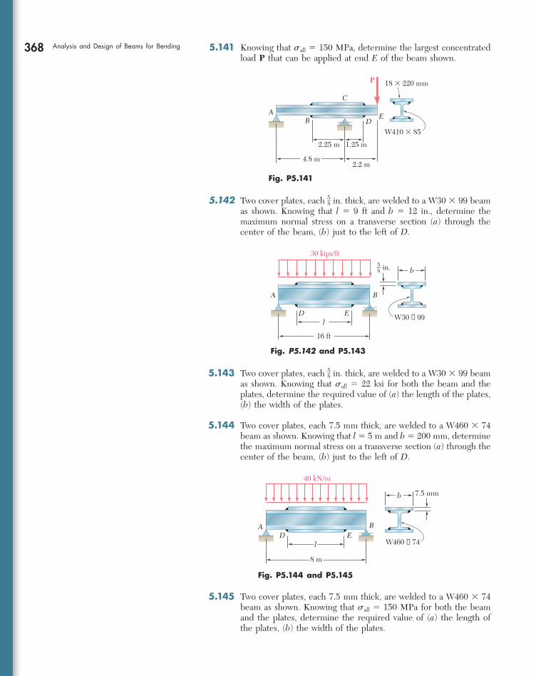
368 Analysis and Design of Beams for Bending 5.141 Knowing that sall 5 150 MPa, determine the largest concentrated load P that can be applied at end E of the beam shown.
E
C
AB D
P
W410 � 85
18 � 220 mm
2.25 m 1.25 m
2.2 m4.8 m
Fig. P5.141
5.142 Two cover plates, each 58 in. thick, are welded to a W30 3 99 beam
as shown. Knowing that l 5 9 ft and b 5 12 in., determine the maximum normal stress on a transverse section (a) through the center of the beam, (b) just to the left of D.
B
b
ED
A
W30 × 99
16 ft
30 kips/ft
in.58
l
Fig. P5.142 and P5.143
B
b 7.5 mm
EDA
l W460 × 74
8 m
40 kN/m
Fig. P5.144 and P5.145
5.143 Two cover plates, each 58 in. thick, are welded to a W30 3 99 beam
as shown. Knowing that sall 5 22 ksi for both the beam and the plates, determine the required value of (a) the length of the plates, (b) the width of the plates.
5.144 Two cover plates, each 7.5 mm thick, are welded to a W460 3 74 beam as shown. Knowing that l 5 5 m and b 5 200 mm, determine the maximum normal stress on a transverse section (a) through the center of the beam, (b) just to the left of D.
5.145 Two cover plates, each 7.5 mm thick, are welded to a W460 3 74 beam as shown. Knowing that sall 5 150 MPa for both the beam and the plates, determine the required value of (a) the length of the plates, (b) the width of the plates.
bee80288_ch05_314-379.indd Page 368 10/27/10 9:58:59 PM user-f499bee80288_ch05_314-379.indd Page 368 10/27/10 9:58:59 PM user-f499 /Volumes/201/MHDQ251/bee80288_disk1of1/0073380288/bee80288_pagefiles/Volumes/201/MHDQ251/bee80288_disk1of1/0073380288/bee80288_pagefiles

369Problems
5.147 Two cover plates, each 12 in. thick, are welded to a W27 3 84 beam
as shown. Knowing that sall 5 24 ksi for both the beam and the plates, determine the required value of (a) the length of the plates, (b) the width of the plates.
5.148 For the tapered beam shown, determine (a) the transverse section in which the maximum normal stress occurs, (b) the largest distrib-uted load w that can be applied, knowing that sall 5 140 MPa.
5.149 For the tapered beam shown, knowing that w 5 160 kN/m, deter-mine (a) the transverse section in which the maximum normal stress occurs, (b) the corresponding value of the normal stress.
5.150 For the tapered beam shown, determine (a) the transverse section in which the maximum normal stress occurs, (b) the largest distrib-uted load w that can be applied, knowing that sall 5 24 ksi.
in.12
B
bED C
A
lW27 × 84
9 ft
160 kips
12 l1
2
9 ft
Fig. P5.146 and P5.147
5.146 Two cover plates, each 12 in. thick, are welded to a W27 3 84 beam
as shown. Knowing that l 5 10 ft and b 5 10.5 in., determine the maximum normal stress on a transverse section (a) through the center of the beam, (b) just to the left of D.
C
x
0.6 m
120 mmA B
hh
0.6 m
300 mm
w 20 mm
Fig. P5.148 and P5.149
A B
x
30 in.
4 in. hh
30 in.
in.34
8 in.
C
w
Fig. P5.150
5.151 For the tapered beam shown, determine (a) the transverse section in which the maximum normal stress occurs, (b) the largest con-centrated load P that can be applied, knowing that sall 5 24 ksi.
x
30 in.
4 in.A BC
hh
30 in.
P
8 in.
in.34
Fig. P5.151
bee80288_ch05_314-379.indd Page 369 10/27/10 9:59:06 PM user-f499bee80288_ch05_314-379.indd Page 369 10/27/10 9:59:06 PM user-f499 /Volumes/201/MHDQ251/bee80288_disk1of1/0073380288/bee80288_pagefiles/Volumes/201/MHDQ251/bee80288_disk1of1/0073380288/bee80288_pagefiles

370
This chapter was devoted to the analysis and design of beams under transverse loadings. Such loadings can consist of concentrated loads or distributed loads and the beams themselves are classified accord-ing to the way they are supported (Fig. 5.22). Only statically deter-minate beams were considered in this chapter, where all support reactions can be determined by statics. The analysis of statically inde-terminate beams is postponed until Chap. 9.
Considerations for the design of prismatic beams
Considerations for the design of prismatic beams
L
(a) Simply supported beam
StaticallyDeterminateBeams
StaticallyIndeterminateBeams
L2L1
(d) Continuous beam
L
(b) Overhanging beam
L
Beam fixed at one endand simply supported
at the other end
(e)
L
(c) Cantilever beam
L
( f ) Fixed beam
Fig. 5.22
y
c
m�
x�Neutral surface
Fig. 5.23
While transverse loadings cause both bending and shear in a beam, the normal stresses caused by bending are the dominant criterion in the design of a beam for strength [Sec. 5.1]. Therefore, this chapter dealt only with the determination of the normal stresses in a beam, the effect of shearing stresses being examined in the next one. We recalled from Sec. 4.4 the flexure formula for the determi-nation of the maximum value sm of the normal stress in a given section of the beam,
sm 5
0M 0 cI
(5.1)
where I is the moment of inertia of the cross section with respect to a centroidal axis perpendicular to the plane of the bending couple M and c is the maximum distance from the neutral surface (Fig. 5.23). We also recalled from Sec. 4.4 that, introducing the elastic section modulus S 5 Iyc of the beam, the maximum value sm of the normal stress in the section can be expressed as
sm 5
0M 0S
(5.3)
It follows from Eq. (5.1) that the maximum normal stress occurs in the section where |M| is largest, at the point farthest from the neutral
Normal stresses due to bending
Shear and bending-moment diagrams
REVIEW AND SUMMARY
bee80288_ch05_314-379.indd Page 370 10/27/10 9:59:16 PM user-f499bee80288_ch05_314-379.indd Page 370 10/27/10 9:59:16 PM user-f499 /Volumes/201/MHDQ251/bee80288_disk1of1/0073380288/bee80288_pagefiles/Volumes/201/MHDQ251/bee80288_disk1of1/0073380288/bee80288_pagefiles

371axis. The determination of the maximum value of |M| and of the critical section of the beam in which it occurs is greatly simplified if we draw a shear diagram and a bending-moment diagram. These diagrams rep-resent, respectively, the variation of the shear and of the bending moment along the beam and were obtained by determining the values of V and M at selected points of the beam [Sec. 5.2]. These values were found by passing a section through the point where they were to be determined and drawing the free-body diagram of either of the portions of beam obtained in this fashion. To avoid any confusion regarding the sense of the shearing force V and of the bending couple M (which act in opposite sense on the two portions of the beam), we followed the sign convention adopted earlier in the text as illustrated in Fig. 5.24 [Examples 5.01 and 5.02, Sample Probs. 5.1 and 5.2].
The construction of the shear and bending-moment diagrams is facilitated if the following relations are taken into account [Sec. 5.3]. Denoting by w the distributed load per unit length (assumed positive if directed downward), we wrote
dVdx
5 2w dMdx
5 V (5.5, 5.7)
or, in integrated form,
VD 2 VC 5 21area under load curve between C and D2 (5.69) MD 2 MC 5 area under shear curve between C and D (5.89)
Equation (5.69) makes it possible to draw the shear diagram of a beam from the curve representing the distributed load on that beam and the value of V at one end of the beam. Similarly, Eq. (5.89) makes it pos-sible to draw the bending-moment diagram from the shear diagram and the value of M at one end of the beam. However, concentrated loads introduce discontinuities in the shear diagram and concentrated couples in the bending-moment diagram, none of which is accounted for in these equations [Sample Probs. 5.3 and 5.6]. Finally, we noted from Eq. (5.7) that the points of the beam where the bending moment is maximum or minimum are also the points where the shear is zero [Sample Prob. 5.4]. A proper procedure for the design of a prismatic beam was described in Sec. 5.4 and is summarized here: Having determined sall for the material used and assuming that the design of the beam is controlled by the maximum normal stress in the beam, compute the minimum allowable value of the section modulus:
Smin 5
ZMZmax
sall (5.9)
For a timber beam of rectangular cross section, S 5 16 bh2,
where b is the width of the beam and h its depth. The dimensions of the section, therefore, must be selected so that 1
6 bh2 $ Smin. For a rolled-steel beam, consult the appropriate table in Appen-dix C. Of the available beam sections, consider only those with a
Relations among load, shear, and bending momentRelations among load, shear, and bending moment
Design of prismatic beamsDesign of prismatic beams
Review and Summary
V
M
M'
V'
(a) Internal forces(positive shear and positive bending moment)
Fig. 5.24
bee80288_ch05_314-379.indd Page 371 11/16/10 7:00:20 PM user-f499bee80288_ch05_314-379.indd Page 371 11/16/10 7:00:20 PM user-f499 /Volumes/201/MHDQ251/bee80288_disk1of1/0073380288/bee80288_pagefiles/Volumes/201/MHDQ251/bee80288_disk1of1/0073380288/bee80288_pagefiles

372 Analysis and Design of Beams for Bending section modulus S $ Smin and select from this group the section with the smallest weight per unit length. This is the most economical of the sections for which S $ Smin.
In Sec. 5.5, we discussed an alternative method for the determina-tion of the maximum values of the shear and bending moment based on the use of the singularity functions Hx 2 aIn. By definition, and for n $ 0, we had
Hx 2 aIn 5 e 1x 2 a2n when x $ a
0 when x , a (5.14)
We noted that whenever the quantity between brackets is positive or zero, the brackets should be replaced by ordinary parentheses, and whenever that quantity is negative, the bracket itself is equal to zero.We also noted that singularity functions can be integrated and dif-ferentiated as ordinary binomials. Finally, we observed that the sin-gularity function corresponding to n 5 0 is discontinuous at x 5 a (Fig. 5.25). This function is called the step function. We wrote
Hx 2 aI0 5 e 1 when x $ a
0 when x , a (5.15)
Singularity functionsSingularity functions
Step functionStep function
0(a) n � 0
� x � a �0
a x
Fig. 5.25
The use of singularity functions makes it possible to represent the shear or the bending moment in a beam by a single expression, valid at any point of the beam. For example, the contribution to the shear of the concentrated load P applied at the midpoint C of a simply supported beam (Fig. 5.26) can be represented by 2P Hx 2 1
2 LI0, since
Using singularity functions to express shear and bending moment
Using singularity functions to express shear and bending moment
BC
A
P
L12 L1
2
Fig. 5.26
bee80288_ch05_314-379.indd Page 372 11/12/10 7:24:36 PM user-f499bee80288_ch05_314-379.indd Page 372 11/12/10 7:24:36 PM user-f499 /Users/user-f499/Desktop/Temp Work/Don't Delete Job/MHDQ251:Beer:201/ch05/Users/user-f499/Desktop/Temp Work/Don't Delete Job/MHDQ251:Beer:201/ch05

373this expression is equal to zero to the left of C, and to 2P to the right of C. Adding the contribution of the reaction RA 5 1
2 P at A, we express the shear at any point of the beam as
V1x2 5 12 P 2 P Hx 2 1
2 LI0
The bending moment is obtained by integrating this expression:
M1x2 5 12 Px 2 P Hx 2 1
2 LI1The singularity functions representing, respectively, the load, shear, and bending moment corresponding to various basic loadings were given in Fig. 5.18 on page 353. We noted that a distributed loading that does not extend to the right end of the beam, or which is dis-continuous, should be replaced by an equivalent combination of open-ended loadings. For instance, a uniformly distributed load extending from x 5 a to x 5 b (Fig. 5.27) should be expressed as
w1x2 5 w0Hx 2 aI0 2 w0Hx 2 bI0
Equivalent open-ended loadingsEquivalent open-ended loadings
Fig. 5.27
xO
w w0
b
L
a
xO
w w0
� w0b
L
a
Review and Summary
The contribution of this load to the shear and to the bending moment can be obtained through two successive integrations. Care should be taken, however, to also include in the expression for V(x) the contribu-tion of concentrated loads and reactions, and to include in the expres-sion for M(x) the contribution of concentrated couples [Examples 5.05 and 5.06, Sample Probs. 5.9 and 5.10]. We also observed that singular-ity functions are particularly well suited to the use of computers.
We were concerned so far only with prismatic beams, i.e., beams of uniform cross section. Considering in Sec. 5.6 the design of nonpris-matic beams, i.e., beams of variable cross section, we saw that by selecting the shape and size of the cross section so that its elastic section modulus S 5 Iyc varied along the beam in the same way as the bending moment M, we were able to design beams for which sm at each section was equal to sall. Such beams, called beams of constant strength, clearly provide a more effective use of the material than prismatic beams. Their section modulus at any section along the beam was defined by the relation
S 5
Msall
(5.18)
Nonprismatic beamsNonprismatic beams
Beams of constant strengthBeams of constant strength
bee80288_ch05_314-379.indd Page 373 11/12/10 7:24:41 PM user-f499bee80288_ch05_314-379.indd Page 373 11/12/10 7:24:41 PM user-f499 /Users/user-f499/Desktop/Temp Work/Don't Delete Job/MHDQ251:Beer:201/ch05/Users/user-f499/Desktop/Temp Work/Don't Delete Job/MHDQ251:Beer:201/ch05

374
REVIEW PROBLEMS
5.152 Draw the shear and bending-moment diagrams for the beam and loading shown, and determine the maximum absolute value (a) of the shear, (b) of the bending moment.
400 lb 1600 lb 400 lb
12 in. 12 in. 12 in. 12 in.
8 in.
8 in.C
AD E F
G
B
Fig. P5.152
5.154 Determine (a) the distance a for which the maximum absolute value of the bending moment in the beam is as small as possible, (b) the corresponding maximum normal stress due to bending. (See hint of Prob. 5.27.)
HA
7 @ 200 mm � 1400 mm
Hinge
30 mm
20 mm
CB D E F G
300 N 300 N 300 N40 N
Fig. P5.153
BAC D
a 5 ft8 ft
W14 � 22
10 kips5 kips
Fig. P5.154
5.153 Draw the shear and bending-moment diagrams for the beam and loading shown and determine the maximum normal stress due to bending.
bee80288_ch05_314-379.indd Page 374 10/27/10 9:59:38 PM user-f499bee80288_ch05_314-379.indd Page 374 10/27/10 9:59:38 PM user-f499 /Volumes/201/MHDQ251/bee80288_disk1of1/0073380288/bee80288_pagefiles/Volumes/201/MHDQ251/bee80288_disk1of1/0073380288/bee80288_pagefiles

375Review Problems5.155 Determine (a) the equations of the shear and bending-moment curves for the beam and loading shown, (b) the maximum absolute value of the bending moment in the beam.
w
A
L
Bx
w � w0 l ( (x2
L2
Fig. P5.155
5.156 Draw the shear and bending-moment diagrams for the beam and loading shown and determine the maximum normal stress due to bending.
A BC
16 kN/m
1 m1.5 m
S150 � 18.6
Fig. P5.156
5.157 Knowing that beam AB is in equilibrium under the loading shown, draw the shear and bending-moment diagrams and determine the maximum normal stress due to bending.
Fig. P5.157
BA
1.2 ft 1.2 ft
C
w0 � 50 lb/ft
T
w0
34 in.
bee80288_ch05_314-379.indd Page 375 10/27/10 10:00:31 PM user-f499bee80288_ch05_314-379.indd Page 375 10/27/10 10:00:31 PM user-f499 /Volumes/201/MHDQ251/bee80288_disk1of1/0073380288/bee80288_pagefiles/Volumes/201/MHDQ251/bee80288_disk1of1/0073380288/bee80288_pagefiles

376 Analysis and Design of Beams for Bending
5.159 Knowing that the allowable stress for the steel used is 160 MPa, select the most economical wide-flange beam to support the loading shown.
5.160 Determine the largest permissible value of P for the beam and loading shown, knowing that the allowable normal stress is 18 ksi in tension and 218 ksi in compression.
P10 in. 10 in.
60 in. 60 in.
1 in.
5 in.
1 in.7 in.
EDCB
A
PP
Fig. P5.160
CDA
B
0.8 m 0.8 m2.4 m
50 kN/m
Fig. P5.159
5.158 For the beam and loading shown, design the cross section of the beam, knowing that the grade of timber used has an allowable normal stress of 1750 psi.
4.8 kips 4.8 kips2 kips 2 kips
F
b
A
2 ft 2 ft 3 ft 2 ft 2 ft
9.5 in.
B C D E
Fig. P5.158
bee80288_ch05_314-379.indd Page 376 10/27/10 10:00:44 PM user-f499bee80288_ch05_314-379.indd Page 376 10/27/10 10:00:44 PM user-f499 /Volumes/201/MHDQ251/bee80288_disk1of1/0073380288/bee80288_pagefiles/Volumes/201/MHDQ251/bee80288_disk1of1/0073380288/bee80288_pagefiles

377Review Problems 5.161 (a) Using singularity functions, find the magnitude and location of the maximum bending moment for the beam and loading shown. (b) Determine the maximum normal stress due to bending.
40 kN/m
1.8 m
AC D
B
1.8 m0.9 m
W530 � 66
60 kN 60 kN
Fig. P5.161
5.162 The beam AB, consisting of an aluminum plate of uniform thick-ness b and length L, is to support the load shown. (a) Knowing that the beam is to be of constant strength, express h in terms of x, L, and h0 for portion AC of the beam. (b) Determine the maximum allowable load if L 5 800 mm, h0 5 200 mm, b 5 25 mm, and sall 5 72 MPa.
w0
Bh h0
L/2 L/2
x
AC
Fig. P5.162
P
d0
HB
A
Fig. P5.163
5.163 A transverse force P is applied as shown at end A of the conical taper AB. Denoting by d0 the diameter of the taper at A, show that the maximum normal stress occurs at point H, which is contained in a transverse section of diameter d 5 1.5 d0.
bee80288_ch05_314-379.indd Page 377 10/27/10 10:00:51 PM user-f499bee80288_ch05_314-379.indd Page 377 10/27/10 10:00:51 PM user-f499 /Volumes/201/MHDQ251/bee80288_disk1of1/0073380288/bee80288_pagefiles/Volumes/201/MHDQ251/bee80288_disk1of1/0073380288/bee80288_pagefiles

378
COMPUTER PROBLEMS
The following problems are designed to be solved with a computer.
5.C1 Several concentrated loads Pi (i 5 1, 2, . . . , n) can be applied to a beam as shown. Write a computer program that can be used to calculate the shear, bending moment, and normal stress at any point of the beam for a given loading of the beam and a given value of its section modulus. Use this program to solve Probs. 5.18, 5.21, and 5.25. (Hint: Maximum values will occur at a support or under a load.)
5.C2 A timber beam is to be designed to support a distributed load and up to two concentrated loads as shown. One of the dimensions of its uniform rectangular cross section has been specified and the other is to be determined so that the maximum normal stress in the beam will not exceed a given allow-able value sall. Write a computer program that can be used to calculate at given intervals DL the shear, the bending moment, and the smallest acceptable value of the unknown dimension. Apply this program to solve the following problems, using the intervals DL indicated: (a) Prob. 5.65 (DL 5 0.1 m), (b) Prob. 5.69 (DL 5 0.3 m), (c) Prob. 5.70 (DL 5 0.2 m).
BA
x1
x2
xnxi
a bL
P1 P2 Pi Pn
Fig. P5.C1
B
t
hA
x1
x3
x2
x4
a bL
P1
P2w
Fig. P5.C2
5.C3 Two cover plates, each of thickness t, are to be welded to a wide-flange beam of length L that is to support a uniformly distributed load w. Denoting by sall the allowable normal stress in the beam and in the plates, by d the depth of the beam, and by Ib and Sb, respectively, the moment of inertia and the section modulus of the cross section of the unreinforced beam about a horizontal centroidal axis, write a computer program that can be used to calculate the required value of (a) the length a of the plates, (b) the width b of the plates. Use this program to solve Prob. 5.145.
bt
EDa
L
w
BA
Fig. P5.C3
bee80288_ch05_314-379.indd Page 378 10/27/10 10:00:58 PM user-f499bee80288_ch05_314-379.indd Page 378 10/27/10 10:00:58 PM user-f499 /Volumes/201/MHDQ251/bee80288_disk1of1/0073380288/bee80288_pagefiles/Volumes/201/MHDQ251/bee80288_disk1of1/0073380288/bee80288_pagefiles

379Computer Problems 5.C4 Two 25-kip loads are maintained 6 ft apart as they are moved slowly across the 18-ft beam AB. Write a computer program and use it to calculate the bending moment under each load and at the midpoint C of the beam for values of x from 0 to 24 ft at intervals Dx 5 1.5 ft.
BC
x
A
18 ft
6 ft
9 ft
25 kips25 kips
Fig. P5.C4
5.C5 Write a computer program that can be used to plot the shear and bending-moment diagrams for the beam and loading shown. Apply this program with a plotting interval DL 5 0.2 ft to the beam and loading of (a) Prob. 5.72, (b) Prob. 5.115.
B
w
A
a
b
L
P
Fig. P5.C5
5.C6 Write a computer program that can be used to plot the shear and bending-moment diagrams for the beam and loading shown. Apply this pro-gram with a plotting interval DL 5 0.025 m to the beam and loading of Prob. 5.112.
B
w
A
b
a
L
MA MB
Fig. P5.C6
bee80288_ch05_314-379.indd Page 379 10/27/10 10:01:08 PM user-f499bee80288_ch05_314-379.indd Page 379 10/27/10 10:01:08 PM user-f499 /Volumes/201/MHDQ251/bee80288_disk1of1/0073380288/bee80288_pagefiles/Volumes/201/MHDQ251/bee80288_disk1of1/0073380288/bee80288_pagefiles