Embed Size (px)
Citation preview
THE BEHAVIOUR OF TANKS ENGULFED IN FIRE - THE
DEVELOPMENT OF A COMPUTER PROGRAM
D L M Hunt* and P K Ramskill*
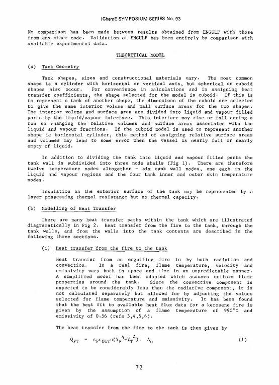
A computer code has been written to predict temperatures and pressure within a tank, partly filled with liquid and completely engulfed in fire. The code models a comprehensive set of heat transfer paths into, through, and within the tank. Bulk boiling of the liquid contents, sonic or subsonic venting through a relief valve, and an option for exterior thermal insulation are included. Code predictions have been found to be in good agreement with experimental data.
INTRODUCTION
Assessment of the safety of liquid filled tanks when engulfed by fire requires the determination of the way in which the temperature of the tank and its contents, and the pressure within the tank vary with time. The Safety and Reliability Directorate have developed a computer code, ENGULF, for the Health and Safety Executive which can perform these functions. The code is being validated by an experimental programme carried out by HSE at Buxton which is the subject of an accompanying paper (1).
The code is made simple and quick to run by using only a small number of nodes within the tank walls. There is, however, adequate modelling of the complex pathways for heat transfer to the tank from the fire and within the tank and its contents. Included also are bulk boiling of the liquid, critical or sub-critical discharge through the relief valve and the option of an external insulation layer. Although intended primarily for hydrocarbon fuels different liquids can be modelled by the use of different liquid and vapour property routines making ENGULF general for any tank contents.
Other fire engulfment codes have been written to model similar situations to ENGULF. One such (2) is written by the Calspan Corporation in the USA. There are similarities between this and ENGULF but significant differences also exist, ie in the modelling of heat transfer within the tank, especially heat transfer to and from the vapour space. ENGULF has a more detailed analysis of the many heat transfer paths within the tank, whereas the Calspan code has a more detailed representation of the tank shell by having many wall temperature nodes. The Calspan code is also specific to propane, as it was developed for LPG carrying tankers and this could make it difficult to adapt for other liquids.
*Safety and Reliability Directorate, Wigshaw Lane, Culcheth, Warrington, WA3 4NE.
71
IChemE SYMPOSIUM SERIES No. 93
No comparison has been made between results obtained from ENGULF with those from any other code. Validation of ENGULF has been entirely by comparison with available experimental data.
THEORETICAL MODEL
(a) Tank Geometry
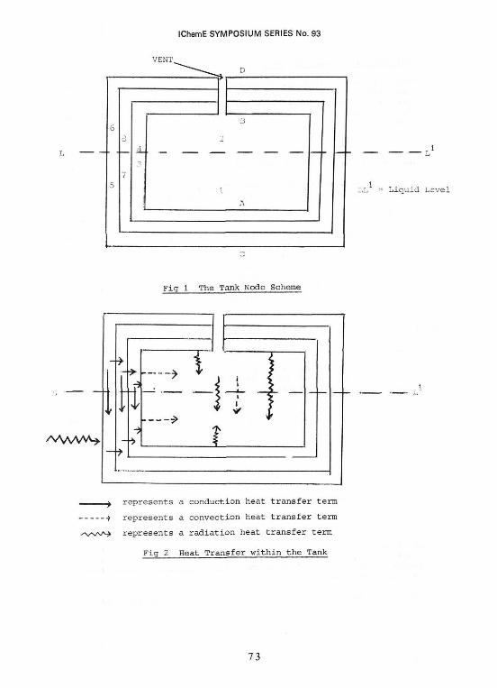
Tank shapes, sizes and constructional materials vary. The most common shape is a cylinder with horizontal or vertical axis, but spherical or cuboid shapes also occur. For convenience in calculations and in assigning heat transfer coefficients, the shape selected for the model is cuboid. If this is to represent a tank of another shape, the dimensions of the cuboid are selected to give the same interior volume and wall surface areas for the two shapes. The interior volume and surface area are divided into liquid and vapour filled parts by the liquid/vapour interface. This interface may rise or fall during a run so changing the relative volumes and surface areas associated with the liquid and vapour fractions. If the cuboid model is used to represent another shape ie horizontal cylinder, this method of assigning relative surface areas and volumes may lead to some error when the vessel is nearly full or nearly empty of liquid.
In addition to dividing the tank into liquid and vapour filled parts the tank wall is subdivided into three node shells (Fig 1). There are therefore twelve temperature nodes altogether - six tank wall nodes, one each in the liquid and vapour regions and the four tank inner and outer skin temperature nodes.
Insulation on the exterior surface of the tank may be represented by a layer possessing thermal resistance but no thermal capacity.
(b) Modelling of Heat Transfer
There are many heat transfer paths within the tank which are illustrated diagramatically in Fig 2. Heat transfer from the fire to the tank, through the tank walls, and from the walls into the tank contents are described in the following three sections.
(i) Heat transfer from the fire to the tank
Heat transfer from an engulfing fire is by both radiation and convection. In a real fire, flame temperature, velocity and emissivity vary both in space and time in an unpredictable manner. A simplified model has been adopted which assumes uniform flame properties around the tank. Since the convective component is expected to be considerably less than the radiative component, it is not calculated separately but allowed for by adjusting the values selected for flame temperature and emissivity. It has been found that the best fit to available heat flux data for a kerosene fire is given by the assumption of a flame temperature of 990°C and emissivity of 0.56 (refs 3,4,5,6).
The heat transfer from the fire to the tank Is then given by
°-FT " eFe0UTo-(YFA-YT
4). A Q (1)
72
IChemE SYMPOSIUM SERIES No. 93
Fig 1 The Tank N.ode Scheme
73
IChemE SYMPOSIUM SERIES No. 93
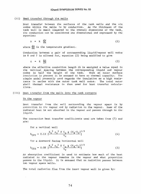
(ii) Heat transfer through the walls
Heat transfer between the surfaces of the tank walls and the six nodes within the walls is by conduction. As the thickness of the tank wall is small compared to the overall dimensions of the tank, the conduction can be considered one dimensional and expressed by the equation:
where is the temperature gradient.
Conduction between a pair of corresponding liquid/vapour wall nodes ie 8 and 7 is allowed for, equation (2) being modified to give
where the effective conduction length Ah is assigned a value equal to the vertical spacing between the corresponding liquid and vapour nodes ie half the height of the tank. When an outer surface insulation is present it is assumed to have no thermal capacity. The simple model presently used regards the insulation as a high resistance in series with the outer tank wall nodes. The total outer shell thermal resistance is then used for heat transfer calculations.
(iii) Heat transfer from the walls into the tank contents
To the vapour
Heat transfer from the wall surrounding the vapour space is by convection to the vapour and by radiation to the vapour. Some of the radiated heat is not absorbed in the vapour and passes through to the liquid.
The convection heat transfer coefficients used are taken from (7) and are:
for a vertical wall
An absorption coefficient is used to estimate how much of the heat radiated to the vapour remains in the vapour and what proportion passes to the liquid. It is assumed that no radiation passes between two vapour space walls.
The total radiation flux from the inner vapour wall is given by:
74
IChemE SYMPOSIUM SERIES No. 93
To the liquid
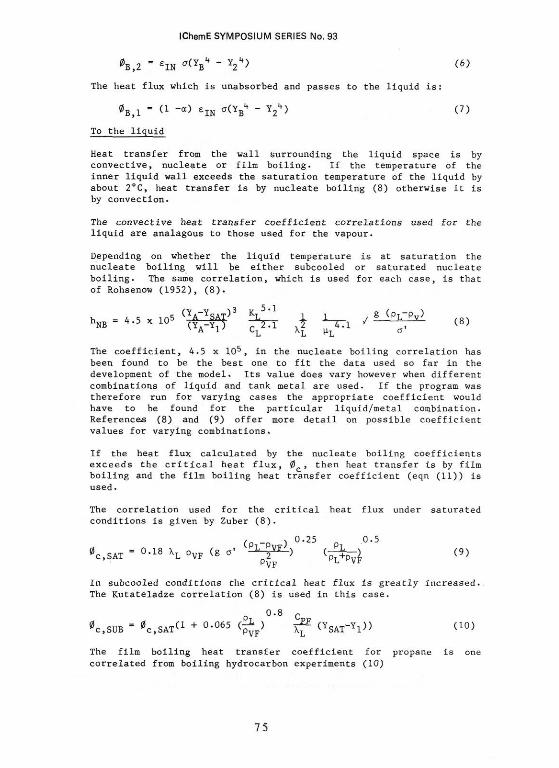
Heat transfer from the wall surrounding the liquid space is by convective, nucleate or film boiling. If the temperature of the inner liquid wall exceeds the saturation temperature of the liquid by about 2°C, heat transfer is by nucleate boiling (8) otherwise it is by convection.
The convective heat transfer coefficient correlations used for the liquid are analagous to those used for the vapour.
Depending on whether the liquid temperature is at saturation the nucleate boiling will be either subcooled or saturated nucleate boiling. The same correlation, which is used for each case, is that of Rohsenow (1952), (8).
The coefficient, 4.5 x 10⁵, in the nucleate boiling correlation has been found to be the best one to fit the data used so far in the development of the model. Its value does vary however when different combinations of liquid and tank metal are used. If the program was therefore run for varying cases the appropriate coefficient would have to be found for the particular liquid/metal combination. References (8) and (9) offer more detail on possible coefficient values for varying combinations.
If the heat flux calculated by the nucleate boiling coefficients exceeds the critical heat flux, 0 , then heat transfer is by film boiling and the film boiling heat transfer coefficient (eqn (11)) is used.
The correlation used for the critical heat flux under saturated conditions is given by Zuber (8).
In subcooled conditions the critical heat flux is greatly increased. The Kutateladze correlation (8) is used in this case.
The film boiling heat transfer coefficient for propane is one correlated from boiling hydrocarbon experiments (10)
The heat flux which is unabsorbed and passes to the liquid is:
75
IChemE SYMPOSIUM SERIES No. 93
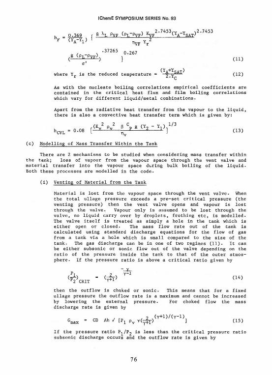
As with the nucleate boiling correlations empirical coefficients are contained in the critical heat flux and film boiling correlations which vary for different liquid/metal combinations.
Apart from the radiative heat transfer from the vapour to the liquid, there is also a convective heat transfer term which is given by:
(c) Modelling of Mass Transfer Within the Tank
There are 2 mechanisms to be studied when considering mass transfer within the tank; loss of vapour from the vapour space through the vent valve and material transfer into the vapour space during bulk boiling of the liquid. Both these processes are modelled in the code.
(i) Venting of Material from the Tank
Material is lost from the vapour space through the vent valve. When the total ullage pressure exceeds a pre-set critical pressure (the venting pressure) then the vent valve opens and vapour is lost through the valve. Vapour only is assumed to be lost through the valve, no liquid carry over by droplets, frothing etc, is modelled. The valve itself is treated as simply a hole in the tank which is either open or closed. The mass flow rate out of the tank is calculated using standard discharge equations for the flow of gas from a tank via a hole which is small compared to the size of the tank. The gas discharge can be in one of two regimes (11). It can be either subsonic or sonic flow out of the valve depending on the ratio of the pressure inside the tank to that of the outer atmosphere. If the pressure ratio is above a critical ratio given by
then the outflow is choked or sonic. This means that for a fixed ullage pressure the outflow rate is a maximum and cannot be increased by lowering the external pressure. For choked flow the mass discharge rate is given by
If the pressure ratio ? is less than the critical pressure ratio subsonic discharge occurs and the outflow rate is given by
76
iChemE SYMPOSIUM SERIES No. 93
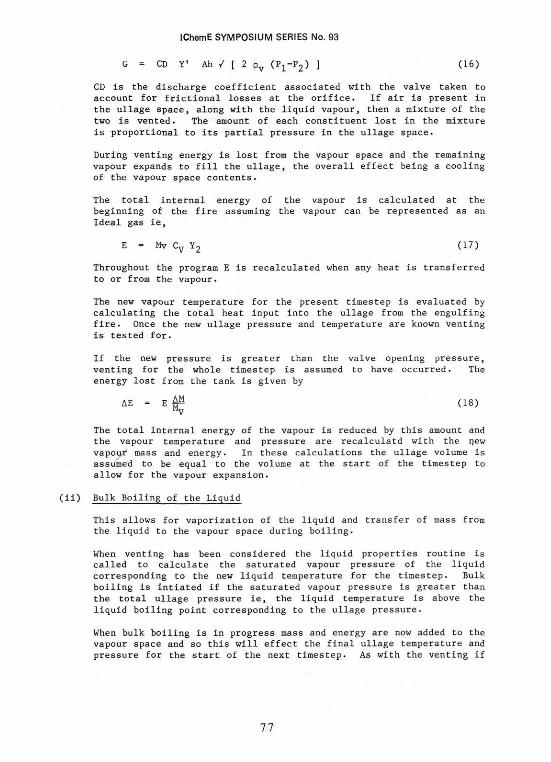
CD is the discharge coefficient associated with the valve taken to account for frictional losses at the orifice. If air is present in the ullage space, along with the liquid vapour, then a mixture of the two is vented. The amount of each constituent lost in the mixture is proportional to its partial pressure in the ullage space.
During venting energy is lost from the vapour space and the remaining vapour expands to fill the ullage, the overall effect being a cooling of the vapour space contents.
The total internal energy of the vapour is calculated at the beginning of the fire assuming the vapour can be represented as an Ideal gas ie,
Throughout the program E is recalculated when any heat is transferred to or from the vapour.
The new vapour temperature for the present timestep is evaluated by calculating the total heat input into the ullage from the engulfing fire. Once the new ullage pressure and temperature are known venting is tested for.
If the new pressure is greater than the valve opening pressure, venting for the whole timestep is assumed to have occurred. The energy lost from the tank is given by
The total internal energy of the vapour Is reduced by this amount and the vapour temperature and pressure are recalculatd with the new vapour mass and energy. In these calculations the ullage volume is assumed to be equal to the volume at the start of the timestep to allow for the vapour expansion.
Bulk Boiling of the Liquid
This allows for vaporization of the liquid and transfer of mass from the liquid to the vapour space during boiling.
When venting has been considered the liquid properties routine is called to calculate the saturated vapour pressure of the liquid corresponding to the new liquid temperature for the timestep. Bulk boiling is intiated if the saturated vapour pressure is greater than the total ullage pressure ie, the liquid temperature is above the liquid boiling point corresponding to the ullage pressure.
When bulk boiling is in progress mass and energy are now added to the vapour space and so this will effect the final ullage temperature and pressure for the start of the next timestep. As with the venting if
77
IChemE SYMPOSIUM SERIES No. 93
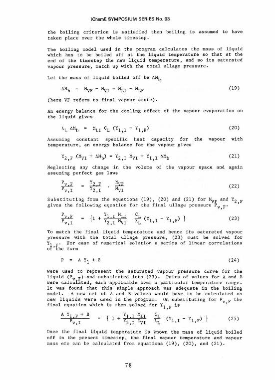
the boiling criterion is satisfied then boiling is assumed to have taken place over the whole timestep.
The boiling model used in the program calculates the mass of liquid which has to be boiled off at the liquid temperature so that at the end of the timestep the new liquid temperature, and so its saturated vapour pressure, match up with the total ullage pressure.
Let the mass of liquid boiled off be
(here VF refers to final vapour state).
An energy balance for the cooling effect of the vapour evaporation on
the liquid gives
Assuming constant specific heat capacity for the vapour with temperature, an energy balance for the vapour gives
Neglecting any change in the volume of the vapour space and again assuming perfect gas laws
To match the final liquid temperature and hence its saturated vapour pressure with the total ullage pressure, (23) must be solved for
For ease of numerical solution a series of linear correlations of'the form
were used to represent the saturated vapour pressure curve for the liquid and substituted into (23). Pairs of values for A and B were calculated, each applicable over a particular temperature range. It was found that this simple approach was adequate in the boiling model. A new set of A and B values would have to be calculated as new liquids were used in the program. On substituting for the final equation which is then solved for is
Once the final liquid temperature is known the mass of liquid boiled off in the present timestep, the final vapour temperature and vapour mass etc can be calculated from equations (19), (20), and (21).
78

IChemE SYMPOSIUM SERIES No. 93
Throughout the fire the height of the liquid in the tank will vary; increasing due to expansion of the liquid as it heats up and decreasing due to boil off of the liquid. These changes in liquid height will affect the relative heat transfer areas to the liquid and vapour masses in the tank. Both effects are modelled in ENGULF. If during the initial expansion of the liquid the ullage becomes less than 5% the program automatically stops as instabilities can occur due to the vapour volume and heat transfer area approaching zero.
(d) Calculation of the Node Temperatures - The Numerical Model
There are 12 temperature nodes within the tank. The temperature at each node is recalculated at every timestep during the fire.
The value of the temperatures at nodes 1 to 8 are found using a fourth order Runge-Kutta algorithm (12).
where
and
is the rate of temperature rise of the ith node for the present
timestep. Expressions for can be found by dividing the net rate of
heat flow into the node over the timestep by the nodes heat capacity. Writing
down for the 8 nodes leads to a series of coupled ordinary differential
equations as each temperature node depends on at least the temperature of the
two adjacent nodes.
The four remaining node temperatures are the inner and outer wall skin temperatures of the liquid and vapour spaces. These temperatures are calculated by balancing the fluxes into and out of the wall surfaces.
79
IChemE SYMPOSIUM SERIES No. 93
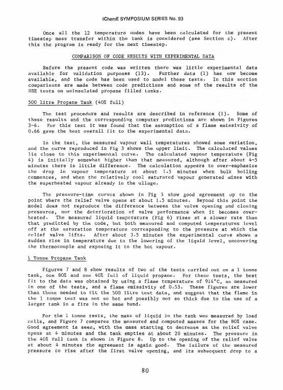
Once all the 12 temperature nodes have been calculated for the present timestep mass transfer within the tank is considered (see Section c) • After this the program is ready for the next timestep.
COMPARISON OF CODE RESULTS WITH EXPERIMENTAL DATA
Before the present code was written there was little experimental data available for validation purposes (13). Further data (1) has now become available, and the code has been used to model these tests. In this section comparisons are made between code predictions and some of the results of the HSE tests on uninsulated propane filled tanks.
500 litre Propane Tank (40% full)
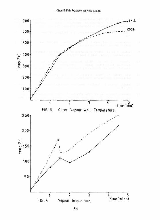
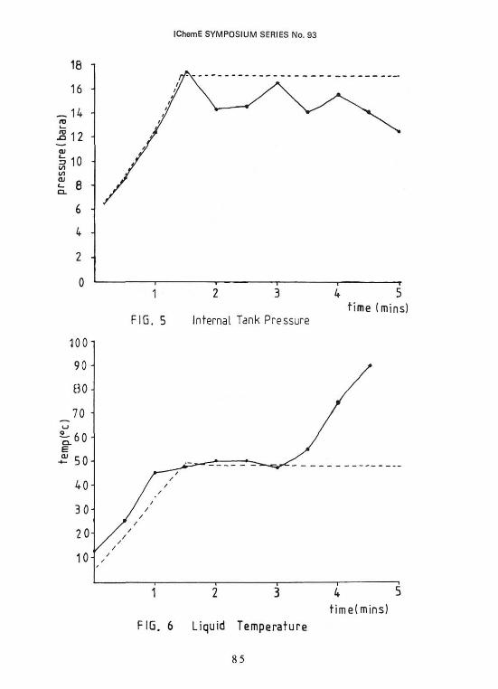
The test procedure and results are described in reference (1). Some of these results and the corresponding computer predictions are shown in Figures 3-6. For this test it was found that the assumption of a flame emissivity of 0.66 gave the best overall fit to the experimental data.
In the test, the measured vapour wall temperatures showed some variation, and the curve reproduced in Fig 3 shows the upper limit. The calculated values lie close to this experimental curve. The calculated vapour temperature (Fig 4) is initially somewhat higher than that measured, although after about 4-5 minutes there is little difference. The calculation appears to over-emphasize the drop in vapour temperature at about 1.5 minutes when bulk boiling commences, and when the relatively cool saturated vapour generated mixes with the superheated vapour already in the ullage.
The pressure-time curves shown in Fig 5 show good agreement up to the point where the relief valve opens at about 1.5 minutes. Beyond this point the model does not reproduce the difference between the valve opening and closing pressures, nor the deterioration of valve performance when it becomes overheated. The measured liquid temperature (Fig 6) rises at a slower rate than that predicted by the code, but both measured and computed temperatures level off at the saturation temperature corresponding to the pressure at which the relief valve lifts. After about 3.5 minutes the experimental curve shows a sudden rise in temperature due to the lowering of the liquid level, uncovering the thermocouple and exposing it to the hot vapour.
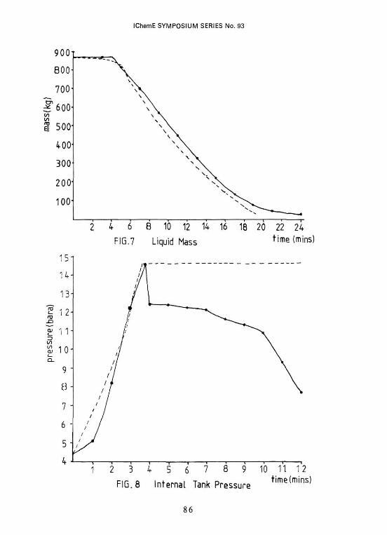
1 Tonne Propane Tank
Figures 7 and 8 show results of two of the tests carried out on a 1 tonne tank, one 80% and one 40% full of liquid propane. For these tests, the best fit to the data was obtained by using a flame temperature of 914°C, as measured in one of the tests, and a flame emissivity of 0.53. These figures are lower than those needed to fit the 500 litre test data, and suggest that the flame in the 1 tonne test was not so hot and possibly not so thick due to the use of a larger tank in a fire in the same bund.
For the 1 tonne tests, the mass of liquid in the tank was measured by load cells, and Figure 7 compares the measured and computed masses for the 80% case. Good agreement is seen, with the mass starting to decrease as the relief valve opens at 4 minutes and the tank empties at about 20 minutes. The pressure in the 40% full tank is shown in Figure 8. Up to the opening of the relief valve at about 4 minutes the agreement is again good. The failure of the measured pressure to rise after the first valve opening, and its subsequent drop to a
80
IChemE SYMPOSIUM SERIES No. 93
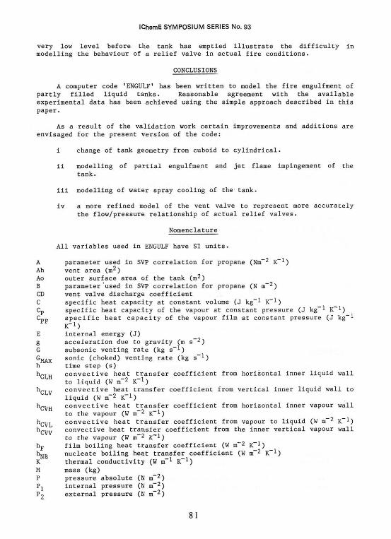
very low level before the tank has emptied illustrate the difficulty in modelling the behaviour of a relief valve in actual fire conditions.
CONCLUSIONS
A computer code 'ENGULF' has been written to model the fire engulfment of partly filled liquid tanks. Reasonable agreement with the available experimental data has been achieved using the simple approach described in this paper.
As a result of the validation work certain improvements and additions are envisaged for the present version of the code:
i change of tank geometry from cuboid to cylindrical.
ii modelling of partial engulfment and jet flame impingement of the tank.
iii modelling of water spray cooling of the tank.
iv a more refined model of the vent valve to represent more accurately the flow/pressure relationship of actual relief valves.
Nomenclature
All variables used in ENGULF have SI units.
81
IChemE SYMPOSIUM SERIES No. 93
References
1. Moodie, K et al, 1984, Proc. of Assessment and control of Major Hazards, I Chem E Conference, Manchester 22-24 April 1985, The fire engulfment of LPG storage tanks.
2. Graves, K W, 1973, Development of a computer program for modelling the heat effects on a railroad tank car. Calspan Corp. Buffalo, NY, CALSPAN YE 5176D1.
3. American Gas Association Project IS-3-1 LNG Safety Program. Interim Report on phase II work (July 1, 1974).
4. Rasbash D J, et al, 'Properties of fires of liquids', Fire Research Station, Boreham Wood, Herts.
5. Law M, 'Structural fire protection in the process industry', Fire Research Station, Boreham Wood, Herts.
8 2
IChemE SYMPOSIUM SERIES No. 93
6. Pope R B, et al, 'An assessment of accident thermal testing and analysis procedures for radioactive materials shipping package1, ASME/AICHE National Heat Transfer Conference, Orlando, Florida, July 27-30, 1980.
7. McAdams W H, Heat Transmission, 3rd Edition, McGraw-Hill Book Co Inc, 1954.
8. Butterworth D and Hewitt G F, 'Two phase flow and heat transfer', AERE Harwell Series, Oxford University Press 1979.
9. Vachan, R et al (1968) 'Evaluation of Constants for Rohsenow Pool Boiling Correlation'. Trans. ASME J Heat Transfer 90C, 239.
10. Sciance C T et al, 'Film boiling measurements and correlation for liquified hydrocarbon gases'. Fundamental Research on Heat and Mass Transfer, Chemical Engineering Progress Symposium Series, No 77, Vol 63.
11. Lees Frank P, 'Loss prevention in the process industries' Vol 1, Butterworth and Company (Publishers) Ltd, 1980.
12. Gerald, Curtis F, 'Applied numerical analysis' Addison-Wesley Publishing Co, 1970.
13. Anderson Charles et al, 'The effects of a fire environment on a rail tank car filled with LPG', US Army Ballistic Research Laboratories, Aberdeen Proving Ground, Maryland, PB 241, September 1974.
8 3
IChemE SYMPOSIUM SERIES No. 93
84
IChemE SYMPOSIUM SERIES No. 93
85
IChemE SYMPOSIUM SERIES No. 93
86