Embed Size (px)
Citation preview
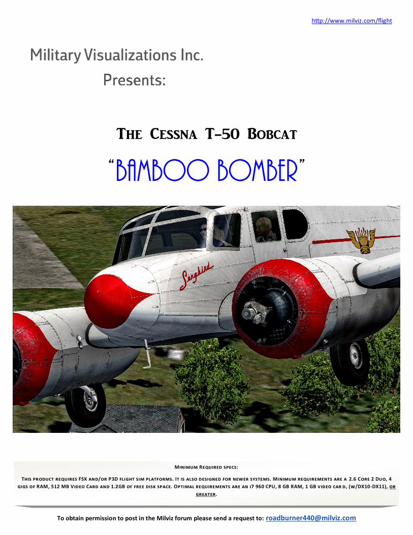
The Cessna T-50 Bobcat
“Bamboo Bomber”
http://www.milviz.com/flight
Minimum Required specs:
This product requires FSX and/or P3D flight sim platforms. It is also designed for newer systems. Minimum requirements are a 2.6 Core 2 Duo, 4
gigs of RAM, 512 MB Video Card and 1.2GB of free disk space. Optimal requirements are an i7 960 CPU, 8 GB RAM, 1 GB video car d, (w/DX10-DX11), or
greater.
To obtain permission to post in the Milviz forum please send a request to: [email protected]
2
http://www.milviz.com/flight 1
1 To obtain permission to post in the Milviz forum please send a request to: [email protected]
Milviz Cessna T-50 Bobcat
Model & Systems Testers
Mike Cameron Beta Tester
Vassilios “Dimus” Dimoulas Beta Tester
David “The Frog” Lawrence Beta Tester
Steve "Slayer" McNitt Beta Tester
Toby Wills Beta Tester
Developers:
Collin Biedenkapp MVAMS
Jonathan Bleeker Cockpit Lighting
Chuck Jodry Secondary Coder
Bill Leaming 3d Modeler and Gauge/Systems Programmer
Mike Maarse Sound Environment
Rick Mackintosh Materials/Livery Texture/ Beta Testing
Dutch Owen Radio Range Sim & Flight Dynamics
Rich Petocz User Guide Text & Design
3D Reach (http://3dreach.com/) Model & Paint
Sergio "Raptor" Sanchez Lights, Animations, FDE
Colin Pearson Military Visualizations Inc.©
77 Mont Royal West, Suite 402 Montréal, QC
Canada • H2T2S5
3
http://www.milviz.com/flight 1
1 To obtain permission to post in the Milviz forum please send a request to: [email protected]
Credits 2
Installation
4
LFR & Radio Range Navigation 5
Startup Procedure 7
Takeoff procedure The T-50 Bobcat Idiosyncrasy 12
TABLE OF CONTENTS
TT HIS PRODUCT IS AN ARTISTIC REPRESENTATION OF THE SUBJECT MATTER. MILITARY VISUALIZATIONS INC. DOES NOT ENDORSE AND IS NOT ENDORSED BY THE MANUFACTURER OF THE SUBJECT MATTER.
NOT ALL SYSTEMS HAVE BEEN SIMULATED AND THOSE WHICH HAVE BEEN SIMULATED ARE DONE SO USING THE LIMITATIONS OF THE MICROSOFT & PREPAR3D FLIGHT SIMULATOR PLATFORMS.
ANY INQUIRIES REGARDING COMMERCIAL, MILITARY OR ACADEMIC USE OF THIS PROGRAM SHOULD BE DIRECTED VIA EMAIL TO
4
http://www.milviz.com/flight 1
1 To obtain permission to post in the Milviz forum please send a request to: [email protected]
II nstalling the Milviz Cessna T-50 Bobcat is simple and no different than most
other FS installations when it comes to ‘pre-installation precautions’. These pre-
cautions include shutting down any programs that are open and disabling any active
antivirus software.
After you’ve downloaded the Milviz Bobcat to your desktop, unzip and open the
folder to find the Cessna T-50 Bobcat installer and then:
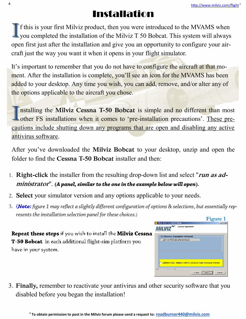
1. Right-click the installer from the resulting drop-down list and select "run as ad-
ministrator". ( ).
2. Select your simulator version and any options applicable to your needs.
3.
Installation
3. Finally, remember to reactivate your antivirus and other security software that you
disabled before you began the installation!
Figure 1
II f this is your first Milviz product, then you were introduced to the MVAMS when
you completed the installation of the Milviz T 50 Bobcat. This system will always
open first just after the installation and give you an opportunity to configure your air-
craft just the way you want it when it opens in your flight simulator.
It’s important to remember that you do not have to configure the aircraft at that mo-
ment. After the installation is complete, you’ll see an icon for the MVAMS has been
added to your desktop. Any time you wish, you can add, remove, and/or alter any of
the options applicable to the aircraft you chose.
5
http://www.milviz.com/flight 1
1 To obtain permission to post in the Milviz forum please send a request to: [email protected]
TT hank you for purchasing the Milviz Cessna T 50 Bobcat! Also known as the “Bamboo
Bomber”, the Milviz team once again went as far as the flight simulator’s capabilities would let
them. We’re sure that you’ll find it to be a very close recreation of the real-world T 50.
This user guide barely scratches the surface of the Bamboo Bomber’s operation and procedures.
However, included in this user guide will be several links that we think you’ll find very in-
teresting if not important.
II n fact, during the time of the T 50s active service lifespan, they used a navigation system known
as “LFR” (low-frequency radio range). This navigation system used a special combination of
tones to tell the pilot which way he had to go in order to reach the airstrip he selected.
Of course, each airstrip of the day had a preassigned “Code”, Morse code Key, and frequency, which
the pilot would listen for and follow, in order to maintain the correct heading to the destination.
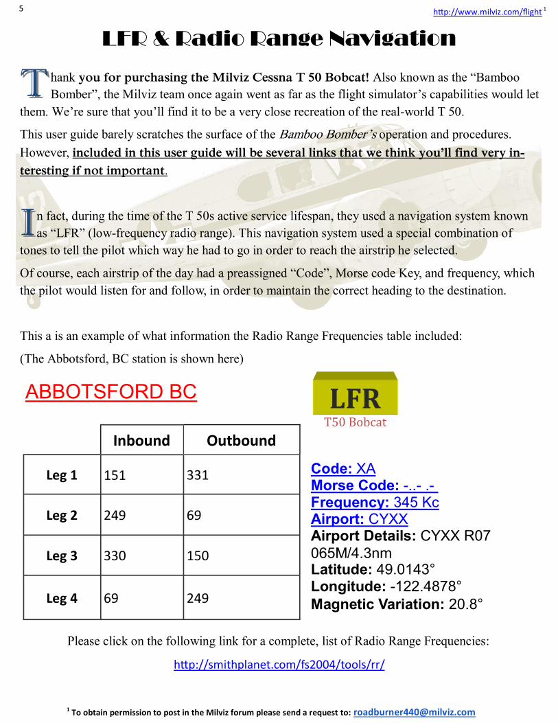
This a is an example of what information the Radio Range Frequencies table included:
(The Abbotsford, BC station is shown here)
Inbound Outbound
Leg 1 151 331
Leg 2 249 69
Leg 3 330 150
Leg 4 69 249
Code: XA Morse Code: -..- .- Frequency: 345 Kc Airport: CYXX Airport Details: CYXX R07
065M/4.3nm Latitude: 49.0143° Longitude: -122.4878°
Magnetic Variation: 20.8°
ABBOTSFORD BC
Please click on the following link for a complete, list of Radio Range Frequencies:
http://smithplanet.com/fs2004/tools/rr/
T50 Bobcat
LFR
LFR & Radio Range Navigation
6
http://www.milviz.com/flight 1
1 To obtain permission to post in the Milviz forum please send a request to: [email protected]
AA very clear and comprehensive tutorial has been prepared instructing exactly how this is ac-
complished. Please refer to this link:
FSX/P3D: Flying the Ranges in the Milviz T-50 Bobcat:
https://www.youtube.com/watch?v=ZQsINQ6qA5c
It’s an excellent, easy to understand, YouTube tutorial which includes an example using an actual
Milviz T 50 flight!
Milviz also supplies a link which contains all the radio range frequencies for the airports that exist-
ed at the time the T 50 Bobcat was in service.
We strongly recommend that you first watch the YouTube tutorial, which will go over the entire
process in detail. Then, refer to this link for your complete list of radio range frequencies assigned
to the airports of the day.
Please click on the following link for the entire, complete, list of Radio Range
Frequencies: http://smithplanet.com/fs2004/tools/rr/
II ncluded with this user guide, is the Pilot’s hand book and several additional manuals that cover
the operation of the T 50 Bobcat.
The Milviz Cessna T 50 installation package also includes a short but detailed, step-by-step proce-
dure on the use of the MVAMS, (Milviz Add-On Management System).
The MVAMS user guide includes the procedure to reestablish your Flight Sim platform, (be it FSX
or P3D based), to a default Cold & Dark, (C&D) or Ready to Fly (RTF) condition.
Upon opening a flight in your sim, you may find your aircraft engines running (or some systems on
and active) even though you chose the C&D option in the MVAMS. If so, then you may need to re-
turn your flight simulator platform to its default “Cold and Dark” condition using the simulator’s de-
fault aircraft, (preferably, the Cessna 172†).
†Please note that the Cessna 172 FSX default aircraft would be the best selection for that platform. For P3D users, a similar aircraft comparable to the Cessna 172 will likely be the best selection as well. Please don’t choose a more complex default aircraft for this procedure. Please refer to the MVAMS guide for detailed instructions.
II t may be useful to know that following this procedure can also correct some anomalies (or in-
creasingly strange behavior ), that you may have been experiencing in your simulator lately.
It’s recommended that you bring your simulator to its default state periodically for that reason alone!
7
http://www.milviz.com/flight 1
1 To obtain permission to post in the Milviz forum please send a request to: [email protected]
Startup ProcedureStartup ProcedureStartup Procedure
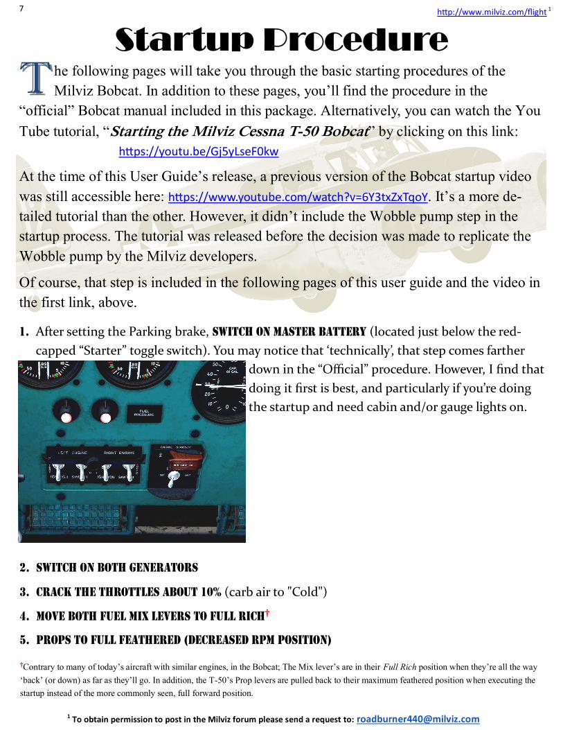
1. After setting the Parking brake, Switch on master battery (located just below the red-
capped “Starter” toggle switch). You may notice that ‘technically’, that step comes farther
down in the “Official” procedure. However, I find that
doing it first is best, and particularly if you’re doing
the startup and need cabin and/or gauge lights on.
TT he following pages will take you through the basic starting procedures of the
Milviz Bobcat. In addition to these pages, you’ll find the procedure in the
“official” Bobcat manual included in this package. Alternatively, you can watch the You
Tube tutorial, “Starting the Milviz Cessna T-50 Bobcat” by clicking on this link:
https://youtu.be/Gj5yLseF0kw
At the time of this User Guide’s release, a previous version of the Bobcat startup video
was still accessible here: https://www.youtube.com/watch?v=6Y3txZxTqoY. It’s a more de-
tailed tutorial than the other. However, it didn’t include the Wobble pump step in the
startup process. The tutorial was released before the decision was made to replicate the
Wobble pump by the Milviz developers.
Of course, that step is included in the following pages of this user guide and the video in
the first link, above.
2. Switch on both Generators
3. Crack the throttles about 10% (carb air to "Cold")
4. Move Both Fuel Mix levers to Full Rich†
5. Props to full feathered (decreased RPM position)
†Contrary to many of today’s aircraft with similar engines, in the Bobcat; The Mix lever’s are in their Full Rich position when they’re all the way ‘back’ (or down) as far as they’ll go. In addition, the T-50’s Prop levers are pulled back to their maximum feathered position when executing the startup instead of the more commonly seen, full forward position.
8
http://www.milviz.com/flight 1
1 To obtain permission to post in the Milviz forum please send a request to: [email protected]
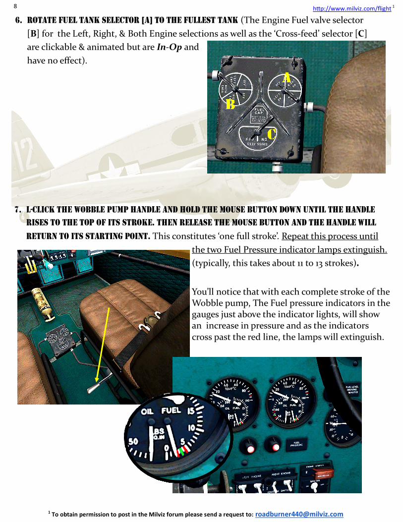
6. Rotate fuel tank selector [A] to the fullest tank (The Engine Fuel valve selector
[B] for the Left, Right, & Both Engine selections as well as the ‘Cross-feed’ selector [C]
are clickable & animated but are In-Op and
have no effect).
7. L-Click the Wobble pump handle and hold the mouse button down until the handle
rises to the top of its stroke. Then release the mouse button and the handle will
return to its starting point. This constitutes ‘one full stroke’. Repeat this process until
the two Fuel Pressure indicator lamps extinguish.
(typically, this takes about 11 to 13 strokes).
You’ll notice that with each complete stroke of the Wobble pump, The Fuel pressure indicators in the gauges just above the indicator lights, will show an increase in pressure and as the indicators cross past the red line, the lamps will extinguish.
9
http://www.milviz.com/flight 1
1 To obtain permission to post in the Milviz forum please send a request to: [email protected]
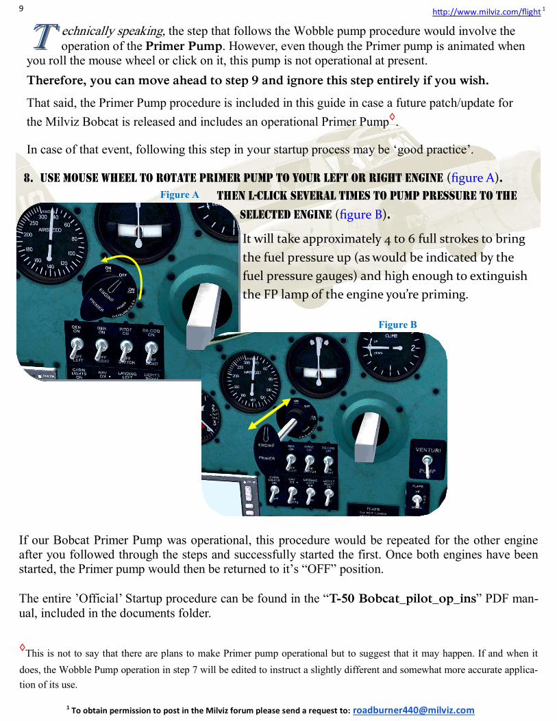
8. Use mouse wheel to rotate primer pump to your left or right engine (figure A).
Then l-click several times to pump pressure to the
selected engine (figure B).
It will take approximately 4 to 6 full strokes to bring
the fuel pressure up (as would be indicated by the
fuel pressure gauges) and high enough to extinguish
the FP lamp of the engine you’re priming.
Figure A
Figure B
◊This is not to say that there are plans to make Primer pump operational but to suggest that it may happen. If and when it
does, the Wobble Pump operation in step 7 will be edited to instruct a slightly different and somewhat more accurate applica-tion of its use.
TT echnically speaking, the step that follows the Wobble pump procedure would involve the
operation of the Primer Pump. However, even though the Primer pump is animated when you roll the mouse wheel or click on it, this pump is not operational at present.
Therefore, you can move ahead to step 9 and ignore this step entirely if you wish.
That said, the Primer Pump procedure is included in this guide in case a future patch/update for
the Milviz Bobcat is released and includes an operational Primer Pump◊.
In case of that event, following this step in your startup process may be ‘good practice’.
If our Bobcat Primer Pump was operational, this procedure would be repeated for the other engine after you followed through the steps and successfully started the first. Once both engines have been started, the Primer pump would then be returned to it’s “OFF” position. The entire ’Official’ Startup procedure can be found in the “T-50 Bobcat_pilot_op_ins” PDF man-ual, included in the documents folder.
10
http://www.milviz.com/flight 1
1 To obtain permission to post in the Milviz forum please send a request to: [email protected]
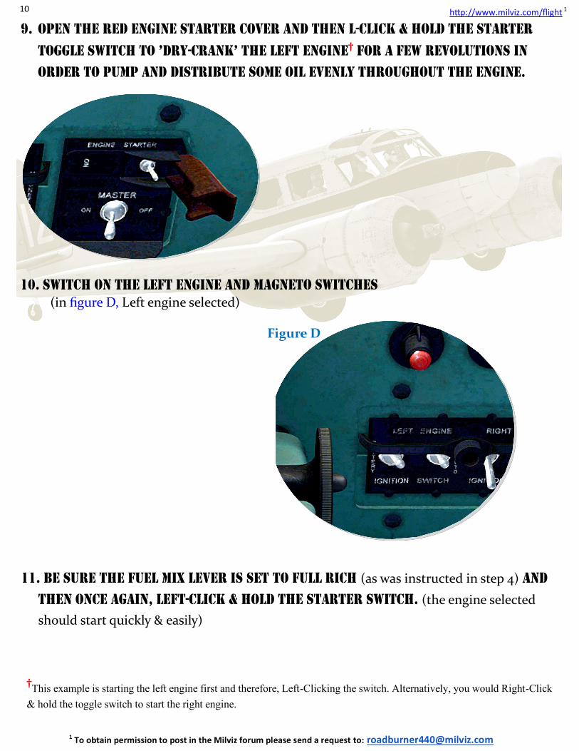
9. Open the red engine starter cover and then L-click & hold the starter
toggle switch to ’dry-crank’ the left engine† for a few revolutions in
order to pump and distribute some oil evenly throughout the engine.
†This example is starting the left engine first and therefore, Left-Clicking the switch. Alternatively, you would Right-Click & hold the toggle switch to start the right engine.
10. Switch on the left engine and magneto switches
(in figure D, Left engine selected)
Figure D
11. Be sure the fuel mix lever is set to full rich (as was instructed in step 4) and
then once again, left-click & hold the starter switch. (the engine selected
should start quickly & easily)
11
http://www.milviz.com/flight 1
1 To obtain permission to post in the Milviz forum please send a request to: [email protected]
12. After starting the first engine, repeat steps 8 through 11 for the remaining
engine.
13. Finally, return the Primer Pump to the center, “OFF” position and close
the Starter switch Cover.
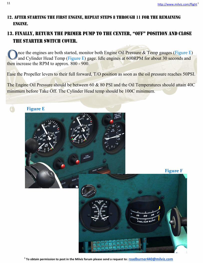
OO nce the engines are both started, monitor both Engine Oil Pressure & Temp gauges (Figure E)
and Cylinder Head Temp (Figure E) gage. Idle engines at 600RPM for about 30 seconds and then increase the RPM to approx. 800 - 900. Ease the Propeller levers to their full forward, T/O position as soon as the oil pressure reaches 50PSI. The Engine Oil Pressure should be between 60 & 80 PSI and the Oil Temperatures should attain 40C
minimum before Take Off. The Cylinder Head temp should be 100C minimum.
Figure E
Figure F

12
http://www.milviz.com/flight 1
1 To obtain permission to post in the Milviz forum please send a request to: [email protected]
Takeoff procedureTakeoff procedureTakeoff procedure
II f there’s one thing most pilots who flew the T-50 would agree on, it’s the way the Bobcat
‘twists’ to the left on take off. The following are some suggestions to counter that ‘twist-
factor’ .
The instructions, (or really, more like suggestions), below are actually a compilation of sugges-
tions from real-world pilots and the like. Some follow all the options given and others only follow
a few. It’s up to you to decide which, if any, you wish to try.
In the screenshot above, the T-50 is on its way down the runway as it gathers up speed for the T/O.
It’s depicting the position of the rudder which is obviously being applied to the right.
Of course, as the throttles are advanced, the characteristic becomes more prevalent, and this occur-
rence in itself is not really all that unusual. For many planes, the increasing torque on the engines
will tend to ‘twist’ the aircraft in the opposite direction of the spinning prop. (Even some jet engines
will do it but it’s not as pronounced.)
However, for the T-50, this characteristic requires more than a little ‘right-rudder’ to correct. The use
of the rudder to correct the problem must be combined with several other applications.
13
http://www.milviz.com/flight 1
1 To obtain permission to post in the Milviz forum please send a request to: [email protected]
TT o get right to it, you may find a combination of some or all of the suggestions in the list below
helpful in keeping the aircraft running straight as it is attaining take-off speed.
Listed below, (and in the order that I personally found each option effective), are the application of
throttle and rudder and how much of each to use, which you may find helpful. I can’t stress enough
that the order of this list is strictly my personal preference.
The content is taken from various, experienced, pilots, (both sim & real-world), which I then com-
bined and tried out. Based on the experience I had with the Milviz T-50 Bobcat each time I took off,
I found them to be very effective.
There are a number of variables and conditions that can significantly impact the effectiveness of
these suggestions, such as, (but not limited to); weather, T/O altitude, barometric pressure & temper-
ature, and of course, gross T/O weight of the aircraft.
UU pon lining up on the runway’s centerline:
Throttle Control, (rudimentary application) Gradually increase both throttles evenly and gently to get the plane rolling.
Rudder Control, (initial operation) As the RPM of the engines and speed of the aircraft begin to increase, start applying right rudder
and increase it as needed to keep the plane moving straight◊.
Throttle Control, (Left throttle Increase) When the right rudder pedal approaches its maximum travel, continue to gently increase the left
throttle but without increasing the right one (Figure G on the following page). Continue with the left throttle until you can reduce some right rudder application and still keep the plane on straight course (approx. 10% more left throttle than right). At that point, resume increasing both throttle lev-ers simultaneously.
Rudder & Throttle control, (Combination) The plane will be building speed and momentum and the rudder’s control surface will begin to be-come increasingly effective. As it does, you’ll begin to feel the plane’s “cooperation” to stay straight on the runway. It’s then that you’ll gradually increase the right throttle to match the left.
Elevator Control As the T-50 increases its speed allow it to ‘decide’ when to raise the tail off the ground. Try not to rush it with the elevator. The tail will rise in time when it’s ready.
◊Some pilots found that applying right rudder trim along with right rudder pedal was sufficient to hold the aircraft straight and no more than that
was needed. Others applied the use of ailerons to work in adjunct to the rudder and/or throttle manipulation.
Takeoff procedure Takeoff procedure Takeoff procedure (cont.)(cont.)(cont.)
14
http://www.milviz.com/flight 1
1 To obtain permission to post in the Milviz forum please send a request to: [email protected]
AA s you could see on the previous page, the control of the throttles are important in assisting the
rudder to correct the twist. This is particularly true when you first start off and the effective-
ness of the rudder’s control surface is negligible at best.
In that phase of the T/O, the rear wheel is probably handling 100% of the action to straighten up the
aircraft. However, it won’t be long before the aircraft reaches a speed fast enough to create a little
lift and considerably reduce the traction and control of the rear gear.
Simultaneously, when the speed has increased to that point, that same speed also happens to be in-
sufficient to offer much more that a ’breeze’ across the rudder’s control surface.
Hmmm…. That could problem.
NN evertheless, you’re very resourceful, (and you’ve gotten used to waking up every morning), so
you reach for alternatives. The list on the previous page for example.
One idea that may come to mind is to pull back on the yoke and try to keep some pressure on the rear
wheel. That may not be of much help when you consider that the same speed was too slow to create
enough airflow for the rudder’s control surface. Therefore, the elevator may be just as handicapped as
the rudder.
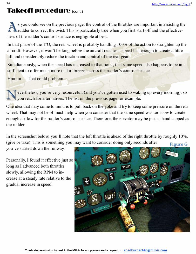
In the screenshot below, you’ll note that the left throttle is ahead of the right throttle by roughly 10%,
(give or take). This is something you may want to consider doing only seconds after
you’ve started down the runway.
Personally, I found it effective just so
long as I advanced both throttles
slowly, allowing the RPM to in-
crease at a steady rate relative to the
gradual increase in speed.
Takeoff procedure Takeoff procedure Takeoff procedure (cont.)(cont.)(cont.)
Figure G
15
http://www.milviz.com/flight 1
1 To obtain permission to post in the Milviz forum please send a request to: [email protected]
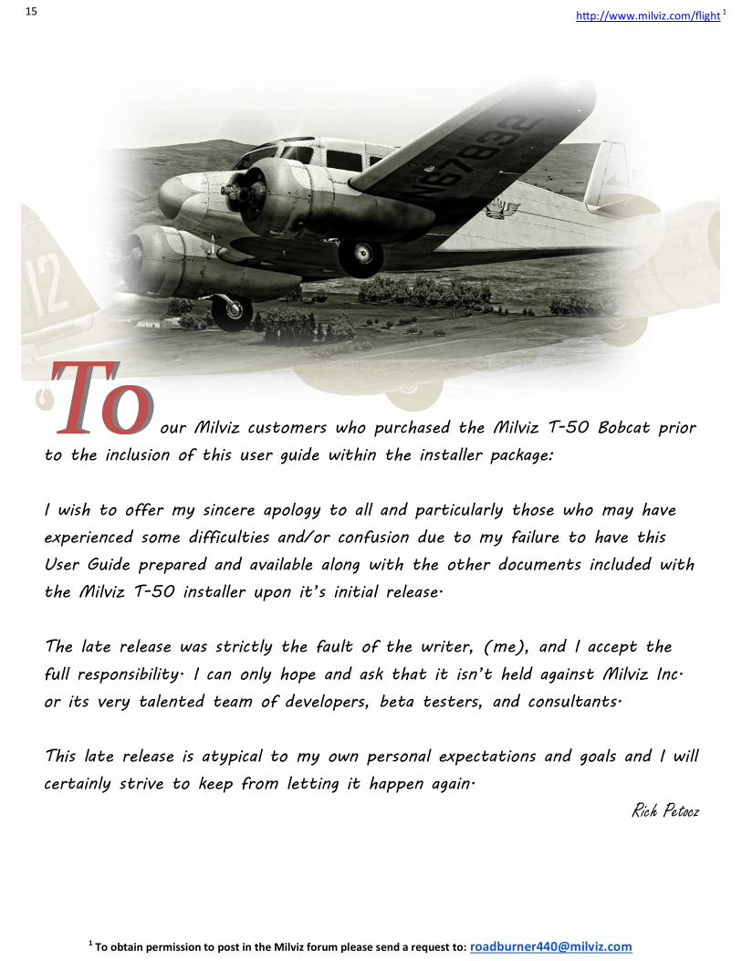
ToTo our Milviz customers who purchased the Milviz T-50 Bobcat prior
to the inclusion of this user guide within the installer package:
I wish to offer my sincere apology to all and particularly those who may have
experienced some difficulties and/or confusion due to my failure to have this
User Guide prepared and available along with the other documents included with
the Milviz T-50 installer upon it’s initial release.
The late release was strictly the fault of the writer, (me), and I accept the
full responsibility. I can only hope and ask that it isn’t held against Milviz Inc.
or its very talented team of developers, beta testers, and consultants.
This late release is atypical to my own personal expectations and goals and I will
certainly strive to keep from letting it happen again.
Rich Petocz


![G.3 (Military aircraft) G.IV (Bomber) G5 automobile · G.III (Bomber) USEFriedrichshafen G.III (Bomber) G.IV (Bomber) USEAEG G.IV (Bomber) G-machine (Computer) (Not Subd Geog) [QA76.8.G]](https://img.pdfslide.net/doc/110x75/5f09a0207e708231d427bb82/g3-military-aircraft-giv-bomber-g5-automobile-giii-bomber-usefriedrichshafen.jpg)