Embed Size (px)
Citation preview
The Danger with Set Screw Locking BearingsBy Victor Wowk, P.E.
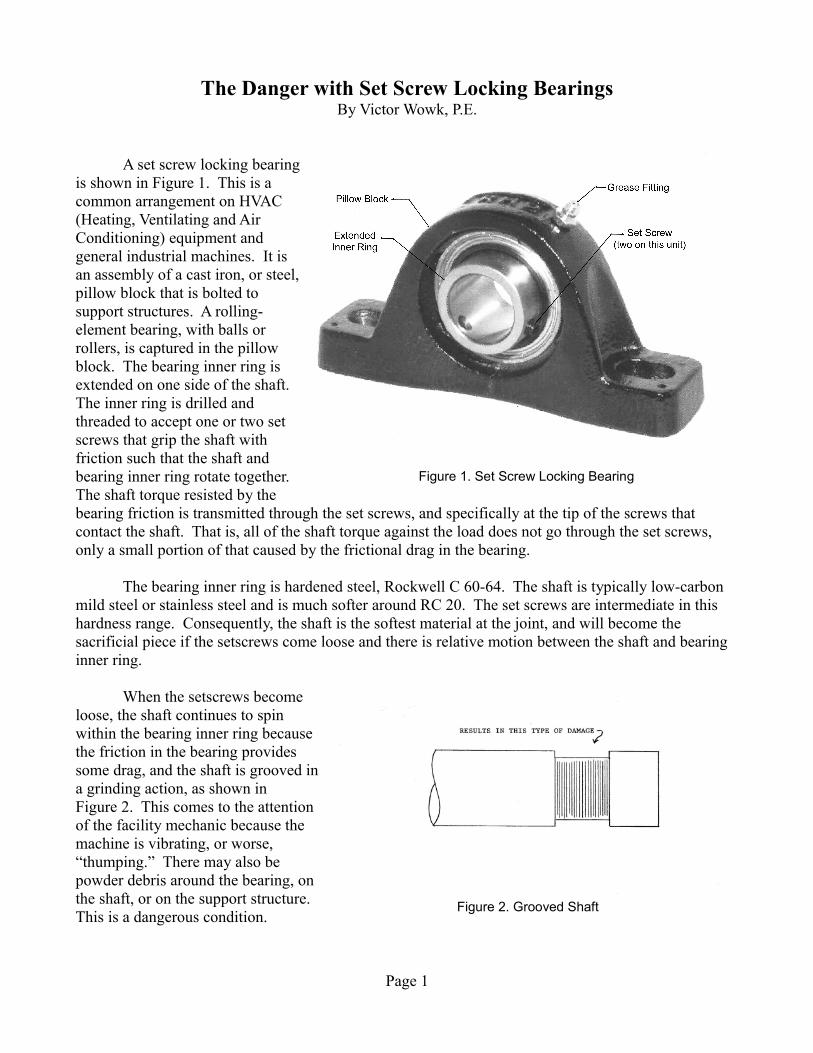
A set screw locking bearingis shown in Figure 1. This is acommon arrangement on HVAC(Heating, Ventilating and AirConditioning) equipment andgeneral industrial machines. It isan assembly of a cast iron, or steel,pillow block that is bolted tosupport structures. A rolling-element bearing, with balls orrollers, is captured in the pillowblock. The bearing inner ring isextended on one side of the shaft.The inner ring is drilled andthreaded to accept one or two setscrews that grip the shaft withfriction such that the shaft andbearing inner ring rotate together.The shaft torque resisted by thebearing friction is transmitted through the set screws, and specifically at the tip of the screws that contact the shaft. That is, all of the shaft torque against the load does not go through the set screws, only a small portion of that caused by the frictional drag in the bearing.
The bearing inner ring is hardened steel, Rockwell C 60-64. The shaft is typically low-carbon mild steel or stainless steel and is much softer around RC 20. The set screws are intermediate in this hardness range. Consequently, the shaft is the softest material at the joint, and will become the sacrificial piece if the setscrews come loose and there is relative motion between the shaft and bearing inner ring.
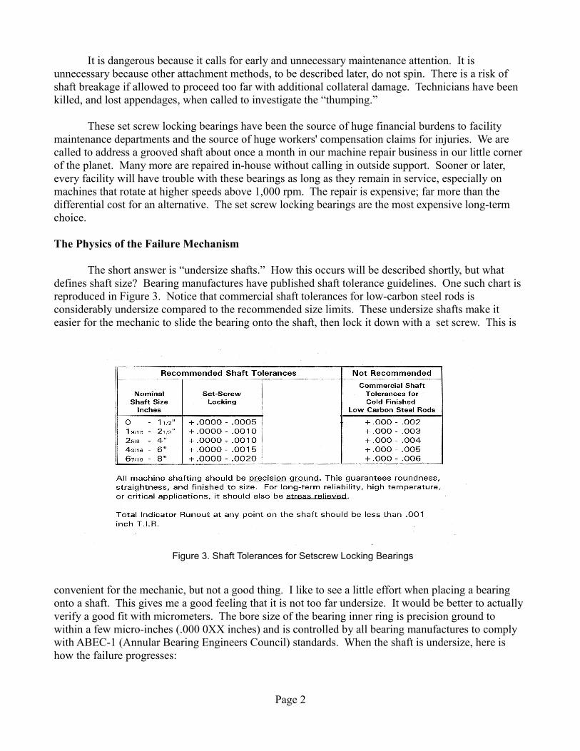
When the setscrews becomeloose, the shaft continues to spinwithin the bearing inner ring becausethe friction in the bearing providessome drag, and the shaft is grooved ina grinding action, as shown inFigure 2. This comes to the attentionof the facility mechanic because themachine is vibrating, or worse,“thumping.” There may also bepowder debris around the bearing, onthe shaft, or on the support structure.This is a dangerous condition.
Page 1
Figure 1. Set Screw Locking Bearing
Figure 2. Grooved Shaft
It is dangerous because it calls for early and unnecessary maintenance attention. It is unnecessary because other attachment methods, to be described later, do not spin. There is a risk of shaft breakage if allowed to proceed too far with additional collateral damage. Technicians have been killed, and lost appendages, when called to investigate the “thumping.”
These set screw locking bearings have been the source of huge financial burdens to facility maintenance departments and the source of huge workers' compensation claims for injuries. We are called to address a grooved shaft about once a month in our machine repair business in our little corner of the planet. Many more are repaired in-house without calling in outside support. Sooner or later, every facility will have trouble with these bearings as long as they remain in service, especially on machines that rotate at higher speeds above 1,000 rpm. The repair is expensive; far more than the differential cost for an alternative. The set screw locking bearings are the most expensive long-term choice.
The Physics of the Failure Mechanism
The short answer is “undersize shafts.” How this occurs will be described shortly, but what defines shaft size? Bearing manufactures have published shaft tolerance guidelines. One such chart is reproduced in Figure 3. Notice that commercial shaft tolerances for low-carbon steel rods is considerably undersize compared to the recommended size limits. These undersize shafts make it easier for the mechanic to slide the bearing onto the shaft, then lock it down with a set screw. This is
convenient for the mechanic, but not a good thing. I like to see a little effort when placing a bearing onto a shaft. This gives me a good feeling that it is not too far undersize. It would be better to actually verify a good fit with micrometers. The bore size of the bearing inner ring is precision ground to within a few micro-inches (.000 0XX inches) and is controlled by all bearing manufactures to comply with ABEC-1 (Annular Bearing Engineers Council) standards. When the shaft is undersize, here is how the failure progresses:
Page 2
Figure 3. Shaft Tolerances for Setscrew Locking Bearings

1. The bearing goes on easily. When the first setscrew is tightened, the shaft is pushed against the far side of the inner ring. This creates an unbalance, which can be corrected with mass balancing after assembly, but more seriously, it distorts the shaft somewhat, and being offsetfrom the roller plane, the inner ring is crooked on the shaft
2. Since there is local distortion at this joint, every rotation produces a tiny “wiggle” of the inner ring pivoting on this point of contact of set screw on shaft.
3. This micro-vibration abradesmaterial at the point of contact,eventually causing a loosening ofthe setscrew.
4. Since the friction generated at thispoint of contact must transmittorque, the loss of frictional contactwill be reduced to the level that itdoes not hold the two together.
5. The shaft is continuously spun bythe motor torque to drive the load.The shaft spins relative to thebearing inner ring which has aslight drag from the roller frictionand viscous drag from the grease,or other lubricant.
6. The shaft continues to spin at full speed driving the load, while the bearing inner ring slows.There is a grinding action of metal on metal.
7. The shaft steel, being softer than the hardened inner ring, has more material removed faster, and becomes the sacrificial victim.
Managing the Situation
This scenario described above is not likely to happen if the shaft is up to full size or near full size, i.e., less than .0005 inch undersize. So one management method is to measure every shaft diameter with micrometers prior to bearing installation to know what you have to deal with. A set of precision micrometers should be in every maintenance department.
If this undersize shaft must be used, then additional procedures can be implemented to manage this situation. They are:
Page 3
Figure 4. Undersize Shaft is offset
1. Counter sink about 1/8-inch depth into the shaft where the setscrew is to seat, and grind the tip of the setscrew to a point. (Most setscrews are “cup point.”) This “pointy” set screw willsit in this countersunk depression and penetrate deeper into the soft shaft steel. This is less likely to loosen, and if it does, then the tip of the set screw will jam against the side of the countersunk pocket and continue to transmit torque.
2. Check set screw tightness periodically• After one hour of run time• Again after one day• Weekly thereafter
3. Daily walk-thru listening for “thumping”
4. Continuous vibration monitoring
Repair Methods
When you are called to address a “thumping” machine and observe that the shaft is already grooved, then there are several repair options.
1. Replace the shaft and bearing. The bearing inner-ring bore size may also have enlarged. This may be an urgent safety decision if the grooving is too deep and the shaft has lost strength. Generally, 25-percent of reduction in shaft diameter is risky to use because the majority of torque transmission and deflection resistance is at the outermost fibers.
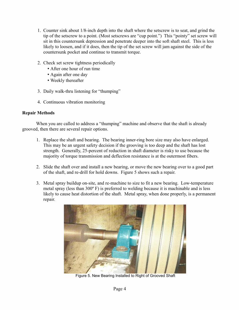
2. Slide the shaft over and install a new bearing, or move the new bearing over to a good part of the shaft, and re-drill for hold downs. Figure 5 shows such a repair.
3. Metal spray buildup on-site, and re-machine to size to fit a new bearing. Low-temperature metal spray (less than 300º F) is preferred to welding because it is machinable and is less likely to cause heat distortion of the shaft. Metal spray, when done properly, is a permanent repair.
Page 4
Figure 5. New Bearing Installed to Right of Grooved Shaft

Alternatives
Set screw locking is the least reliable method of securing a bearing to a shaft. It should only be used on low torque (like rotary switches on electronic instruments) and low speed (less than 20 rpm) mechanisms. There are better choices that do not spin. They are:
1. Keys to transmit torque. This is not often seen on facility equipment, but keyed inner rings are available.
2. Threaded shafts with a locknut that secure the bearing against a shaft shoulder
3. Eccentric locking collars
4. Tapered shafts with tapered inner rings and a nut on a threaded shaft
5. Tapered adapters with split sleeves that squeeze down onto a shaft, and also centers it to preserve balance
6. Various proprietary mechanisms, such as:• Grip Tight® Dodge• Squeeze Lock® SealMaster• Taper lock bearings from several manufactures is another alternative
Another alternative is to design the shaft to use plain, sleeve, or babbit bearings. The shaft always spins on a lubricant film and the babbit is softer than shaft steel so the babbit wears, preserving the shaft. It is easier to replace bearings rather than the shaft.
A final alternative is to just delete the bearings. This is always a fall-back engineering option—to just deplete a problematic part. Belts and pulleys are an out-of-date technology that can be replaced with a variable-speed drive and a motor coupled directly to the driven rotor. This is mechanically more reliable because it deletes parts, i.e., belts, pulleys, shaft, and two bearings go away.A variable-speed drive adds electronic complexity, but is safer for mechanics and easier to repair.
Engineering Solutions
What should be done, from an engineering perspective, to address this unsafe and costly situation in industry with set screw locking bearings?
First, I wish that manufactures would stop making them. This, I know, is unlikely because they have a financial incentive to continue selling more replacement bearings. They are also sensitive to thelowest-cost purchaser. Original equipment manufactures who continue to make or use set screw locking bearings identify themselves as “cheap” with little regard for quality, reliability, or customer safety. If manufactures, or OEM's, feel so strong that their product is good, then they should offer a lifetime guarantee that their bearings will never spin before the rollers wear out.
Page 5

Second, machine designers should exclude these bearings in their assemblies.
Third, engineers who write specifications should not allow them to be substituted.
Fourth, general and mechanical contractors who do installations should not allow them on their new construction projects.
Fifth, architects and engineers should reject submittals that show them.
Sixth, owners should not accept them on their premises.
Seventh, maintenance technicians should replace them with something better at the first opportunity.
Finally, the federal government, with their oversight on public safety, should step up to their responsibilities and, at least, study the situation. Ultimately, OSHA (Occupational Safety and Health Administration) should ban set screw locking bearings, just like the FDA bans dangerous chemicals, the DOT bans unsafe products, and the FAA regulates components on aircraft.
Victor Wowk, P.E., is the president of Machine Dynamics, Inc., located in Rio Rancho, andAlbuquerque, New Mexico. His contact information is available at www.machinedyn.com.
Page 6

![Lifting and Locking Mechanism - Transporter Engtransporter-eng.com/files/lifting-locking-mechanism.pdf · Screw Lifting ] 5õln's gemier car transporter RANSPORTER Hunwick Engineering](https://img.pdfslide.net/doc/110x75/5f4b23031c4f7c3fc420dc3f/lifting-and-locking-mechanism-transporter-engtransporter-engcomfileslifting-locking-.jpg)