Embed Size (px)
Citation preview

TS05J - Hydrography in Practice, paper no 5200 Harry Wirth and Thomas Brüggemann The development of a multiple transducer multi-beam echo sounder system for very shallow waters FIG Working Week 2011 Bridging the Gap between Cultures Marrakech, Morocco, 18-22 May 2011
1/15
The Development of a Multiple Transducer Multi-beam Echo Sounder System for Very Shallow Waters
Harry WIRTH and Thomas BRÜGGEMANN, Germany
Key words: Multi-beam echo sounder; very shallow-water survey; triple-head MBES SUMMARY In 2008, the German Federal Institute of Hydrology (BfG) was commissioned to investigate possibilities of improving the effectiveness of multi-beam echo sounders for the use on inland waterways. The BfG identified parameters for the optimisation of a combined multi-beam system that consisted of two Kongsberg EM 3002 echo sounders, one equipped with a dual-head transducer and one with a single-head transducer. The system was designed for maximum efficiency in waters deeper than 2 m. Moreover, the shape and the size of the boat hull define the dynamical behaviour of the survey vessel, what can have considerable influence on the accuracy of measurements and on the navigability. To find the best compromise, the dynamic behaviour of a catamaran vessel was tested. In field tests it was shown that the survey can be made at a cruising velocity of 12 km/h without putting the required data density at risk. On most inland waterways this new system may increase the output of measurements by at least 120% (compared between conventional and new system the size of a surveyed area in the same time is increased by a factor of 2.2). Thereupon the waterways and shipping administration (WSV) of Germany procured a “triple head” multi-beam system in the autumn of 2010. During the process of acceptance and commissioning new deficiencies occurred, which were caused by the transducer mounting. There were failures of the hydraulic transducer lifting device and lots of false measurements due to the bow waves. These technical problems could be solved, respectively a compromise was reached. The system was put to full operation at the end of March 2011. The paper will furthermore present examples of the system efficiency on the small River Main, for the survey of dams, sheet pilings and other objects.

TS05J - Hydrography in Practice, paper no 5200 Harry Wirth and Thomas Brüggemann The development of a multiple transducer multi-beam echo sounder system for very shallow waters FIG Working Week 2011 Bridging the Gap between Cultures Marrakech, Morocco, 18-22 May 2011
2/15
The Development of a Multiple Transducer Multi-beam Echo Sounder
System for Very Shallow Waters
Harry WIRTH and Thomas BRÜGGEMANN, Germany 1. INTRODUCTION The Federal Waterways and Shipping Administration (WSV) wanted to increase the efficiency of the conventional hydrographic multi-beam echo sounder systems. This objective was derived from the need to lower the production costs by getting the same quality and output with less resources. Therefore in 2008, the German Federal Institute of Hydrology (BfG) was commissioned to investigate possibilities of improving the effectiveness of multi-beam echo sounders for the use on inland waterways. 2. SYSTEM CONCEPT The efficiency of hydrographic surveying systems using multi-beam echo sounders may be increased by maximizing the area covered by the measuring signal (maximized transversal beam aperture) and by increasing the speed of the surveying vessel. However, to ensure the proper analysis and reliability of the measurement results, a minimum density of 5-10 measuring points per square metre must be provided. Moreover, overlapping with the neighbouring swathes should be minimized. [WIRTH H., 2008] The system has to be designed for maximum efficiency in waters deeper than 1.5 m. The following concept is based on the assumption that the multi-beam echo sounder forms the beams according to the ”equidistant” principle. [BRÜGGEMANN Th., WIRTH H. 2007] 2.1 Combined MBES with optimization of the transducer alignment It is intended to maximize the swathe width by combining two multi-beam echo sounders in such a way that full coverage of the area under the vessel is achieved. The outer transducers should be as little tilted against the horizontal as possible, so that the gap in coverage to fill below the vessel remains minimal. When the outer transducers are inclined by 25°, the outer beams with 75° tilt angle (measured against nadir) can be shifted to 90° for inspections of buildings or near-bank areas, i.e. the measurement can be made parallel to the water surface (see Figure 1). Provided the transducer heads are mounted at the vessel at a depth of 0.5 m, this alignment is suitable to close the gap in coverage below the ship's hull already at a water depth of 1.50 m by means of a third transducer, if the distance between the outer transducers is not more than 6 m. If they are 9 metres apart, the water depth must be more than 2.01 m.

TS05J - Hydrography in Practice, paper no 5200 Harry Wirth and Thomas Brüggemann The development of a multiple transducer multi-beam echo sounder system for very shallow waters FIG Working Week 2011 Bridging the Gap between Cultures Marrakech, Morocco, 18-22 May 2011
3/15
To avoid deterioration of the accuracy of coordinates when transferring them to the transducer centres, eccentricities between heave-roll-pitch sensors, positioning system and transducers must be kept at a minimum. [WIRTH H., 2008]
Figure 1: Optimized transducer alignment with two combined multibeam echosounders 2.2 Optimizing swathe-width planning and the survey vessel type To ensure the preservation of the minimum density of measurements, the overlap of the swathes should be chosen so that influences of imprecise navigation along survey route (about ±2-3 m), the roll of the vessel and the variation of swath width caused by varying water depth are compensated. If the swathes are oriented parallel to the depth layers, a swathe overlap of 5 m is sufficient in evenly sloped, structurally less diversified terrain. In practical application it is necessary to plan the survey routes on the basis of previous surveys. When the outer oscillators are tilted by 25°, roll movements of the vessel reduce the effective aperture angle of 2 x 75° (each referenced to the nadir). Accordingly it is essential for the survey vessel to keep stable in the water. The roll angles should be ≤ ±3°. Directional stability can be achieved with vessels of more than 20 m length. [WIRTH H., 2008] 3. RESULTS OF THE FIELD TESTS The tests were made with the EM 3002 by Kongsberg on the survey vessel ”Johannes Kepler” of the Waterways and Shipping Directorate South (WSD Süd). The mounting was temporarily fixed to the vessel following the instructions given by the BfG.
75° 25°
65°40°
Min. depth for complete coverage

TS05J - Hydrography in Practice, paper no 5200 Harry Wirth and Thomas Brüggemann The development of a multiple transducer multi-beam echo sounder system for very shallow waters FIG Working Week 2011 Bridging the Gap between Cultures Marrakech, Morocco, 18-22 May 2011
4/15
t
Figure 1: Survey vessel PS “Johannes Kepler” Signal superposition between the transducers had to be suppressed or avoided by controlled triggering of the signals of the combined echo sounder systems. 3.1 Survey-vessel test The shape and the size of the boat hull define the dynamical behaviour of the survey vessel, what can have considerable influence on its navigability and on the accuracy of measurements. To find the best compromise, the dynamic behaviour of a catamaran vessel (MS “Visurgis”) was tested and evaluated in comparison with standard vessels (like the MB “Reiher”) in dependence on manoeuvres, waves, wind, and cross currents.
Figure 2: Roll angles of the survey boats on a curved course Being a catamaran, the survey boat „Visurgis“ shows only 1/5th of the roll movements of the standard survey boats „Reiher“ in monohull design. Thus, the "Visurgis" type meets the limits
PS “Johannes Kepler” Length: 33,2m Width: 8,88m
welded MBES transducer makeshift-mounting

TS05J - Hydrography in Practice, paper no 5200 Harry Wirth and Thomas Brüggemann The development of a multiple transducer multi-beam echo sounder system for very shallow waters FIG Working Week 2011 Bridging the Gap between Cultures Marrakech, Morocco, 18-22 May 2011
5/15
of ±3° required for the combined echo sounder system without problems. The catamaran design also allows very exact navigation along the planned survey route. [BÖTH H. 2009] 3.2 Multibeam investigation and improvement The transversal standard mounting angle of the dual-head-(v-shaped) MBES used to be 40°. In order to eliminate or minimize the influence of total reflexions, the installation angles of the transducers were varied. The computed theoretical optimal value of 25° was verified in practical tests. The field tests yielded an unacceptable number of severe errors in the measurements (see the Figure 2 and left-hand picture in Figure 2). We observed different categories of causes for the erroneous measurements:
Errors due to multiple signal paths in areas with very firm subsoil (see left-hand picture in Figure 3 and 4, green measurements seemingly below the seafloor);
Errors due to signal interferences between the main lobe and the side lobes (blue and red measurements seemingly above the seafloor);
Errors due to strongly reflecting small and compact objects (e.g. rip-rap stones). The EM 3002 still was not suitable (see figure 3). Therefore the bottom-detector algorithms of the EM3002 had to be improved by Kongsberg.
Figure 3: 3D view of one swathe before system improvement
transducer positions
faulty measurements

TS05J - Hydrography in Practice, paper no 5200 Harry Wirth and Thomas Brüggemann The development of a multiple transducer multi-beam echo sounder system for very shallow waters FIG Working Week 2011 Bridging the Gap between Cultures Marrakech, Morocco, 18-22 May 2011
6/15
Figure 4: Error performance of the system before (left picture) and after the modification Furthermore the required triggering of the MBES reduced the frequency of soundings nearly to its half, i.e. to about 9 Hz. Because of the even distribution of measuring points with the equidistant mode, the minimum density of points within one swathe could still be achieved at a speed over ground of 12-13 km/h. The remaining critical marginal areas are sufficiently filled by overlapping neighbour swathes. [BRÜGGEMANN Th., WIRTH H. 2010] After further development and modifications, the system was working with satisfactory reliability and accuracy (see right-hand picture in Figure 4). 4. PERFORMANCE IN OPERATION The tests proved the general applicability of a combined multi-beam echo sounder system on the basis of the EM3002 by Kongsberg Maritime. Thereupon the WSV procured a “triple head” multi-beam system in the autumn of 2010. The vessel was modified until the end of 2010. In this phase the existing multi channel echo sounder sweep-system fitted to booms had to be dismantled and the new hydraulic lifting devices had to be installed. During the process of acceptance and commissioning new deficiencies occurred. In the following chapters the new technical problems are described and how they were overcome. The system was put to full operation at the end of March 2011. The paper gives some examples of the system efficiency in different application areas. 4.1 Mounting of the transducers The WSD Süd wanted to avoid high constructional expense and decided not to build an external mounting out of influence of the bow waves as it was the case during the field tests. Therefore the hydraulic lifting devices were mounted at the nearest position to the bow in the freeboard deck (see figure 5 left). For the acceptance and commissioning several tests were carried out. Due to the bow waves
TS05J - Hydrography in Practice, paper no 5200 Harry Wirth and Thomas Brüggemann The development of a multiple transducer multi-beam echo sounder system for very shallow waters FIG Working Week 2011 Bridging the Gap between Cultures Marrakech, Morocco, 18-22 May 2011
7/15
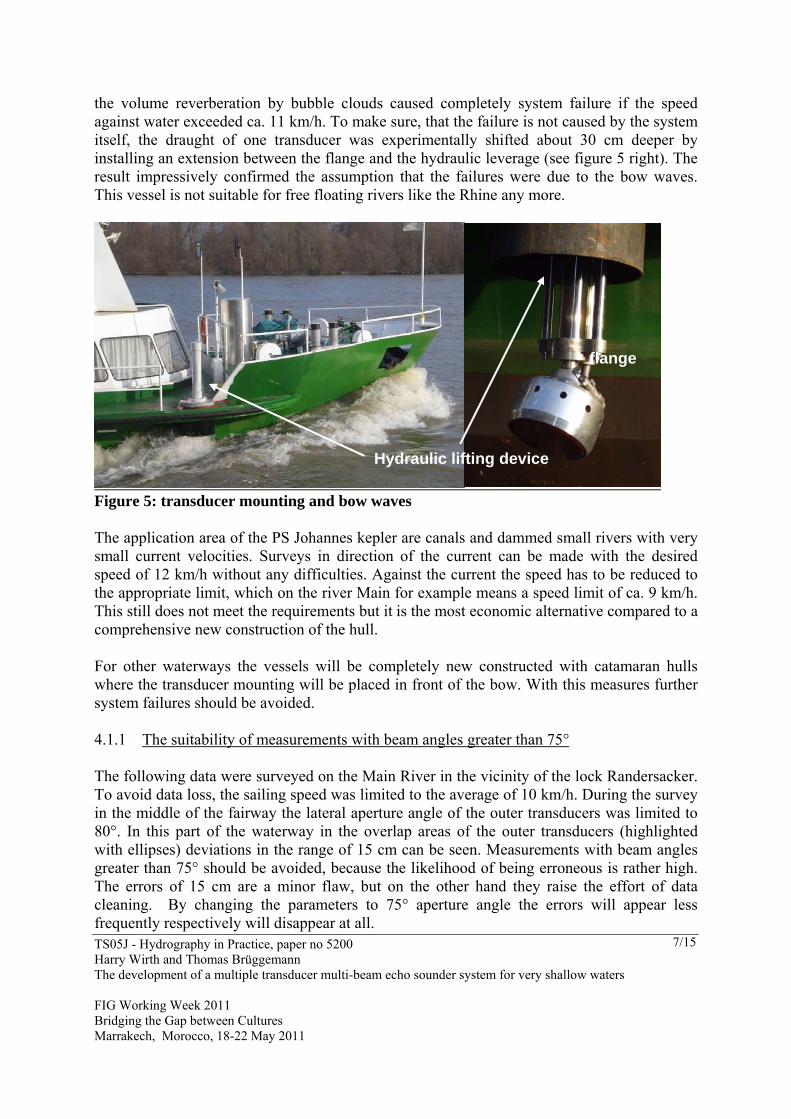
the volume reverberation by bubble clouds caused completely system failure if the speed against water exceeded ca. 11 km/h. To make sure, that the failure is not caused by the system itself, the draught of one transducer was experimentally shifted about 30 cm deeper by installing an extension between the flange and the hydraulic leverage (see figure 5 right). The result impressively confirmed the assumption that the failures were due to the bow waves. This vessel is not suitable for free floating rivers like the Rhine any more.
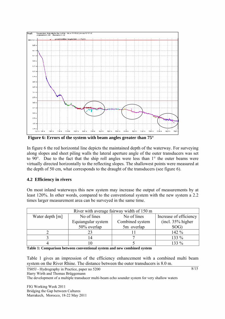
Figure 5: transducer mounting and bow waves The application area of the PS Johannes kepler are canals and dammed small rivers with very small current velocities. Surveys in direction of the current can be made with the desired speed of 12 km/h without any difficulties. Against the current the speed has to be reduced to the appropriate limit, which on the river Main for example means a speed limit of ca. 9 km/h. This still does not meet the requirements but it is the most economic alternative compared to a comprehensive new construction of the hull. For other waterways the vessels will be completely new constructed with catamaran hulls where the transducer mounting will be placed in front of the bow. With this measures further system failures should be avoided. 4.1.1 The suitability of measurements with beam angles greater than 75° The following data were surveyed on the Main River in the vicinity of the lock Randersacker. To avoid data loss, the sailing speed was limited to the average of 10 km/h. During the survey in the middle of the fairway the lateral aperture angle of the outer transducers was limited to 80°. In this part of the waterway in the overlap areas of the outer transducers (highlighted with ellipses) deviations in the range of 15 cm can be seen. Measurements with beam angles greater than 75° should be avoided, because the likelihood of being erroneous is rather high. The errors of 15 cm are a minor flaw, but on the other hand they raise the effort of data cleaning. By changing the parameters to 75° aperture angle the errors will appear less frequently respectively will disappear at all.
Hydraulic lifting device
flange
TS05J - Hydrography in Practice, paper no 5200 Harry Wirth and Thomas Brüggemann The development of a multiple transducer multi-beam echo sounder system for very shallow waters FIG Working Week 2011 Bridging the Gap between Cultures Marrakech, Morocco, 18-22 May 2011
8/15
Figure 6: Errors of the system with beam angles greater than 75° In figure 6 the red horizontal line depicts the maintained depth of the waterway. For surveying along slopes and sheet piling walls the lateral aperture angle of the outer transducers was set to 90°. Due to the fact that the ship roll angles were less than 1° the outer beams were virtually directed horizontally to the reflecting slopes. The shallowest points were measured at the depth of 50 cm, what corresponds to the draught of the transducers (see figure 6). 4.2 Efficiency in rivers On most inland waterways this new system may increase the output of measurements by at least 120%. In other words, compared to the conventional system with the new system a 2.2 times larger measurement area can be surveyed in the same time.
River with average fairway width of 150 m Water depth [m] No of lines
Equiangular system 50% overlap
No of lines Combined system
5m overlap
Increase of efficiency(incl. 35% higher
SOG) 2 23 11 142 % 3 14 7 133 % 4 10 5 133 %
Table 1: Comparison between conventional system and new combined system Table 1 gives an impression of the efficiency enhancement with a combined multi beam system on the River Rhine. The distance between the outer transducers is 8.0 m.

TS05J - Hydrography in Practice, paper no 5200 Harry Wirth and Thomas Brüggemann The development of a multiple transducer multi-beam echo sounder system for very shallow waters FIG Working Week 2011 Bridging the Gap between Cultures Marrakech, Morocco, 18-22 May 2011
9/15
4.3 Efficiency in canals and small rivers The heretofore used multichannel echo sounders with booms covered a width of roundabout 40 m with one sweep. With the small overlap of the neighbour swathes of 5m two lines are sufficient to cover the canals. A third line was necessary for transferring the vessel to the following application area. With the implementation of the new combined multi-beam system the numbers of lines stay the same (see figure 7), but the considerably higher speed increases the efficiency in canals about 67%.
Figure 7: survey line geometry in canals Small rivers in Germany which also serve as waterways often have a width of about 90-100 between waters edges. In figure 8 the River Main is shown as example. The level of this dammed waters and the fairway are plotted as red lines. In practise with the new system is no difference to the situation in canals. Two swathes are not quite sufficient for full coverage, but switching on the data collection while sailing the third line which was formerly used only for return closes the small gap between the two first swathes. [WIRTH H., 2008]
water level width in canals 55,0m
5m
7,47m
Distance between swathes: 29,05m
0,97m
Waterdepth 4,0m
4,0m
EM3002 Measurement area width 52,0m
Uncertainty of navigation
Reduction of overlap due to roll angle
Slope 1:3

TS05J - Hydrography in Practice, paper no 5200 Harry Wirth and Thomas Brüggemann The development of a multiple transducer multi-beam echo sounder system for very shallow waters FIG Working Week 2011 Bridging the Gap between Cultures Marrakech, Morocco, 18-22 May 2011
10/15
Figure 8: Cross section of a dammed small river To make clear where profile 1 to 3 begin and end, the corresponding areas were additionally sketched above the original data (figure 8). The shallowest points were also measured at the depth of 50 cm. 4.4 Data density and accuracy of single measurements and model surfaces Insufficient data density reduces the reliability of data cleaning and makes it difficult to compute high resolution digital terrain models. Therefore in the quality management standards of the WSV of Germany homogeneously distributed data are claimed. A minimum data density of 5-10 measurements/m2 must be provided.
Figure 9: Colour-coded data density in meshes (size 1x1 m)
Profile 1 Profile 2
Profile 3
TS05J - Hydrography in Practice, paper no 5200 Harry Wirth and Thomas Brüggemann The development of a multiple transducer multi-beam echo sounder system for very shallow waters FIG Working Week 2011 Bridging the Gap between Cultures Marrakech, Morocco, 18-22 May 2011
11/15
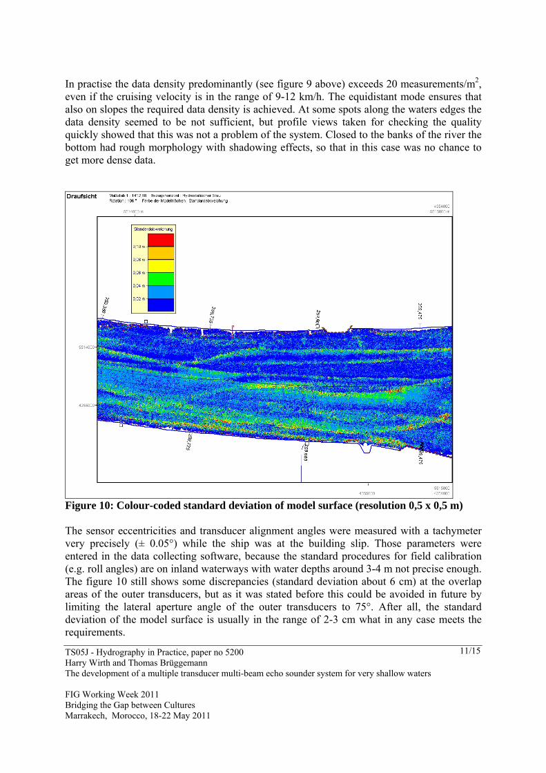
In practise the data density predominantly (see figure 9 above) exceeds 20 measurements/m2, even if the cruising velocity is in the range of 9-12 km/h. The equidistant mode ensures that also on slopes the required data density is achieved. At some spots along the waters edges the data density seemed to be not sufficient, but profile views taken for checking the quality quickly showed that this was not a problem of the system. Closed to the banks of the river the bottom had rough morphology with shadowing effects, so that in this case was no chance to get more dense data.
Figure 10: Colour-coded standard deviation of model surface (resolution 0,5 x 0,5 m) The sensor eccentricities and transducer alignment angles were measured with a tachymeter very precisely (± 0.05°) while the ship was at the building slip. Those parameters were entered in the data collecting software, because the standard procedures for field calibration (e.g. roll angles) are on inland waterways with water depths around 3-4 m not precise enough. The figure 10 still shows some discrepancies (standard deviation about 6 cm) at the overlap areas of the outer transducers, but as it was stated before this could be avoided in future by limiting the lateral aperture angle of the outer transducers to 75°. After all, the standard deviation of the model surface is usually in the range of 2-3 cm what in any case meets the requirements.

TS05J - Hydrography in Practice, paper no 5200 Harry Wirth and Thomas Brüggemann The development of a multiple transducer multi-beam echo sounder system for very shallow waters FIG Working Week 2011 Bridging the Gap between Cultures Marrakech, Morocco, 18-22 May 2011
12/15
Figure 11: model surface (gridded data 1x1 m) The WSV has defined the characteristics of a so called multi purpose model: The deviations between the model surface and the measurements must be in the size of the accuracy of the measurements. All further generalized models with lower resolution are based on this gridded data. Figure 11 shows this model type with the resolution of 1m. Applying the Cardinal theorem of Interpolation Theory for frequencies (sampling theorem) to model resolution, objects of the size of 2 m can be determined in satisfactory quality with the showed resolution of 1m. For special purposes like inspection of underwater buildings you might need higher resolutions. [WIRTH H., BRÜGGEMANN Th., 2010] 4.5 The suitability for the inspection of underwater constructions The predecessor EM 3000 solely formed beams in equiangular mode. The lateral data density declined with higher beam angles. This mode was not suitable for surveys in areas with rough morphology or underwater constructions. The equidistant mode of the EM 3002 now ensures homogeneous data density in each ping as long as the morphology causes no shadowing effects. This is the prerequisite for the survey and modelling of underwater constructions, embankments of rivers or groynes. However the equidistant mode is not a special feature of the combined multi beam echo sounder. Especially in canals the WSV wants to detect embankment erosions early enough to protect the sensible base layers. [BRÜGGEMANN Th., WIRTH H. 2010] With the resulting high data density, the model resolution can be increased to 0.25 m what makes it possible to distinguish even objects in the size of rip-rap stones. In the following drawing (see figure 12) The high quality of the survey can directly be seen in the right-hand picture of the concrete wall. The surface of the object is visibly plane and smooth. In comparism to this the rip-rap stones on the other side of the dam could be displayed in detail.

TS05J - Hydrography in Practice, paper no 5200 Harry Wirth and Thomas Brüggemann The development of a multiple transducer multi-beam echo sounder system for very shallow waters FIG Working Week 2011 Bridging the Gap between Cultures Marrakech, Morocco, 18-22 May 2011
13/15
Figure 12: 3D picture of a dam with 0,25m model; left-hand picture shows a dam with
rip-rap stones; right-hand picture shows a concrete wall The last example shows a typical profile through a swath measured against a sheet piling wall.
Figure 13: profile of a sheet piling wall with a corridor width of 1m The erroneous data at the bottom of the wall is due to multiple paths of the signal. In this case the signals were first reflected on the wall and then on the bottom. This is a problem of the bottom detector algorithm of the EM 3002 which has its weakness with firm soils. This is also the cause for the outliers at the end of the profile. We are still trying to motivate the company Kongsberg to join our endeavour to enhance the system efficiency by improving the existing bottom detector.

TS05J - Hydrography in Practice, paper no 5200 Harry Wirth and Thomas Brüggemann The development of a multiple transducer multi-beam echo sounder system for very shallow waters FIG Working Week 2011 Bridging the Gap between Cultures Marrakech, Morocco, 18-22 May 2011
14/15
This picture impressively underlines the advantage of the equidistant mode and evidently shows the excellent suitability of the system for the inspection of underwater constructions. 5. CONCLUSION The tests proved the general applicability of a combined multi-beam echo sounder system on the basis of the EM3002 by Kongsberg Maritime. In the field tests it was shown that surveys can be made at a cruising velocity of 12 km/h without putting the required data density at risk. Moreover, it was shown that on inland waterways the combined system makes it possible to increase efficiency significantly by some 120% against the conventional multi-beam echo sounder systems. The alignment of the transducers suggested by the BfG proved to be practicable. Below water depths of 2m the combined echo sounder system is more efficient than multi-channel system with swinging booms (sweep sounder). The requirements on data transfer and evaluation increase with a combined triple-head MBES insignificantly, if at all, against a dual-head system. REFERENCES BÖTH H. 2009, Fachtechnische Stellungnahme zur Lagestäbilität und Linienführung des Messschiffes „Visurgis“. BfG-Gutachten unveröffentlicht, Koblenz. BRÜGGEMANN Th., WIRTH H. 2007, Vergleich der Fächerlotsysteme EM 3000 und EM 3002, BfG-Bericht 1529, Koblenz. BRÜGGEMANN Th., WIRTH H. 2010, Optimierung der Gerätetechnik und Geräteträger in der Gewässervermessung, Abschlussbericht. BfG-Bericht 1661, Koblenz. WIRTH H., 2008, Optimierung der Gerätetechnik und Geräteträger in der Gewässervermessung, Zwischenbericht. BfG-Bericht 1605, Koblenz. WIRTH H., BRÜGGEMANN Th., 2010, Surveying of extremely shallow waters with optimised multi-beam echo sounders and survey vessels, presentation at HYDRO 2010, Rostock-Warnemünde, http://www.hydro2010.com/

TS05J - Hydrography in Practice, paper no 5200 Harry Wirth and Thomas Brüggemann The development of a multiple transducer multi-beam echo sounder system for very shallow waters FIG Working Week 2011 Bridging the Gap between Cultures Marrakech, Morocco, 18-22 May 2011
15/15
BIOGRAPHICAL NOTES Dipl.-Ing. Harry Wirth Studies of Geodesy at the Rheinische Friedrich-Wilhelms University 1980-1986 Diplom-Ingenieur degree 1986; Trainee for public service in cadastral surveying and mapping authorities in Germany 1986-1988; Employee at the German Federal Institute of Hydrology (BfG) since 1988; Head of the team for hydrography (development and testing of survey systems and methods for surveying and evaluating of data); Since 2010, Deputy Head of the Department Geodesy in the BfG; since 2010 Member of the German Hydrographic Society, Deutscher Verein für Vermessungswesen (DVW); Member of the DVW Working Group III, Measuring methods and systems. Dipl.-Ing. Thomas Brüggemann Studies of surveying and mapping at the Fachhochschule Bochum 1989-1992 Employee at the federal institute of hydrology germany since 1992 Works in the team for hydrography (development and testing of survey systems and methods for surveying and evaluating of data) CONTACT Dipl.-Ing. Harry Wirth and Dipl.-Ing. Thomas Brüggemann, both at German Federal Institute of Hydrology Am Mainzer Tor 1 56002 Koblenz GERMANY Tel. +4926113065232 Fax + 4926113065280 Email: [email protected], [email protected] Web site: bafg.de