Embed Size (px)
Citation preview
Nationaal Lucht- en Ruimtevaartlaboratorium National Aerospace Laboratory NLR
NLR-TP-2004-141
The development of composite landing gear components for aerospace applications
H.G.S.J. Thuis
This report has been based on a paper presented at Society of Allied Weight Engineers International Conference, at Newport Beach California 17-19 May 2004. This report may be cited on condition that full credit is given to NLR and the author.
Customer: National Aerospace Laboratory NLR Working Plan number: AV.3.E Owner: National Aerospace Laboratory NLR Division: Aerospace Vehicles Distribution: Unlimited Classification title: Unclassified April 2004 Approved by author:
Approved by project manager: Approved by project managing department:

-3-
NLR-TP-2004-141
Contents
Abstract 5 Introduction 6 Composite Torque Link development 7 The metal reference torque link 7 The composite torque link design 8 Fabrication of the composite torque links 8 Testing the composite torque links 9 F-16 drag brace development 10
Materials used and material properties 11 Detailed design 11 Sub-component testing 12 Description of the tooling concept 13 Manufacturing of the RTM drag braces 14 Test program 16
NH-90 Trailing arm development 18
The metal reference Trailing arm 18 The composite trailing arm concept 19 Fabrication of the composite trailing arm 19
Conclusions 22 References 23 18 Figures
(23 pages in total)
-4-
NLR-TP-2004-141
SAWE Paper No. 3333
Category: Advanced Technology and Materials
The development of composite landing gear components for aerospace applications
Bert G.S.J. Thuis, Head Structures Technology Department
National Aerospace Laboratory NLR
For Presentation at the 63rd Annual Conference
of Society of Allied Weight Engineers, Inc.
Newport Beach, California, 17-19 May, 2004
Permission to publish this paper, in full or in part, with credit to the author and the Society may be obtained, by request, to:
Society of Allied Weight Engineers, Inc.
P.O. Box 60024, Terminal Annex Los Angeles, CA 90060
The Society is not responsible for statements or opinions in papers or discussions at the meeting.
-5-
NLR-TP-2004-141
Abstract
Composites are being used increasingly for structural components for aircraft and space applications because of their superior specific strength and stiffness properties in comparison aluminum and steel. The weight savings that were realized by applying composites used to be one of the main drivers to apply these materials. However, nowadays a reduction in fabrication cost is becoming important as well. The objective therefore is to combine new cost effective fabrication methods with lightweight structural concepts in order bring the exploitation of composite materials to a higher level. Up to now, the autoclave process is the standard fabrication technique to produce composite components for the aerospace industry. Recent developments show the evolution of new cost efficient fabrication techniques and of composite materials for these new techniques. One of these (for the aerospace) new fabrication methods is Resin Transfer Moulding (RTM). The RTM fabrication concept is based on the injection of resin into a mould cavity containing dry fibers (preform). During the injection process, air in the mould is being replaced by resin and the fibers are impregnated. Although RTM tooling can be complex and expensive, RTM has several advantages compared to autoclave processing. One of these advantages is that thick complex shaped components can be made that would be very cumbersome or even impossible to make by autoclave processing. This means that designers now can design composite components as replacement of components made with metal forging. In the framework of several technology programs the Structures Technology Department as part of the Aerospace Vehicles division of NLR developed several composite landing gear components for a large military helicopter and a fighter aircraft. These programs were carried out in close collaboration with the landing gear manufacturer SP aerospace and vehicle systems. The targets of the programs were to achieve not only weight reductions of 20% but also to reduce the manufacturing costs by 15% and to achieve a reduction in lead-time. Several different landing gear components were fabricated successfully by RTM and tested. All tested landing gear components failed beyond their required failure load levels. All program targets were met. The present paper will present an overview of the design concepts of these composite landing gear components. The RTM tooling concepts and the RTM manufacturing set-ups will be described and a brief overview of the test results will be given. Based on the results achieved, composite landing gear components are now considered to be feasible for application in next generation civil and military aircraft.
-6-
NLR-TP-2004-141
Introduction
Composites are being increasingly used for structural components for aircraft and space applications because of their superior specific strength and stiffness properties in comparison aluminum and steel. The weight savings that were realized by applying composites used to be one of the main drivers to apply these materials. However, nowadays a reduction in fabrication cost is becoming important as well. The objective therefore is to combine new cost effective fabrication methods with lightweight structural concepts in order bring the exploitation of composite materials to a higher level. Up to now, the autoclave process is the standard fabrication technique to produce composite components for the aerospace industry. Recent developments show the evolution of new cost efficient fabrication techniques and of composite materials for these new techniques. One of these (for the aerospace) new fabrication methods is Resin Transfer Moulding (RTM). The RTM fabrication concept is based on the injection of resin into a mould cavity containing dry fibers (preform). During the injection process, air in the mould is being replaced by resin and the fibers are impregnated. Although RTM tooling can be complex and expensive, RTM has several advantages compared to autoclave processing: • Matched die tooling concepts can be used, assuring tight outer dimensional tolerances,
hence reducing the amount of shimming during assembly • Net-shaped or nearly net-shaped components can be made, hence reducing the amount of
trimming after curing the composite component • Complex shaped thick components can be made that would be very cumbersome or even
impossible to produce by autoclave processing. The RTM fabrication concept makes it possible for designers to replace metal forging by composite components. This opens the door for designers to develop composite landing gear components. In order to demonstrate the feasibility of composite materials in landing gear applications, NLR carried out several technology programs. These programs were carried out in close collaboration with the landing gear manufacturer SP aerospace and vehicle systems. The main targets of these programs were to realize a cost reduction of 15% and a weight reduction of 20% by replacing metal landing gear components by composite components. The present paper presents the development of three different landing gear elements: a torque link for a helicopter, a drag brace for a fighter aircraft and a trailing arm for a helicopter. The design concepts will be described followed by a description of the manufacturing process. Most of the landing gear components were tested. The paper will present a brief overview of these test programs followed with a presentation of the test results.
-7-
NLR-TP-2004-141
Composite Torque Link development
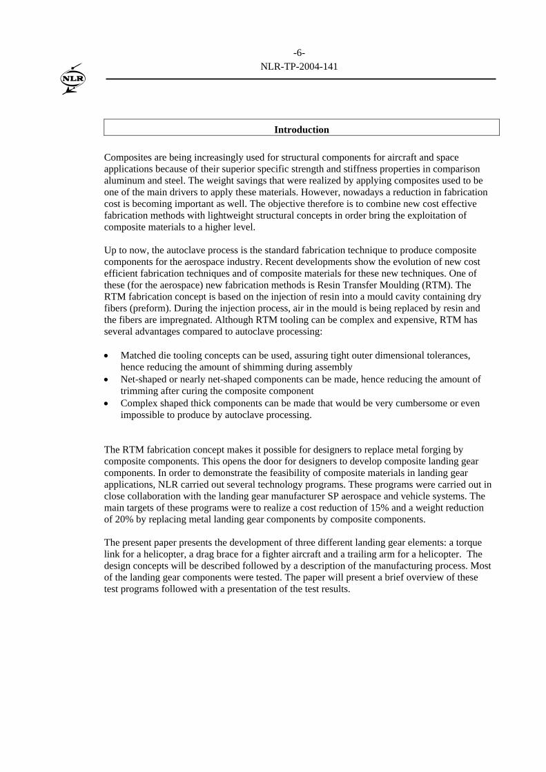
The first composite landing gear component that was developed at NLR was a torque link for the main landing gear of the NH-90 helicopter. In landing gear applications a torque link is used to prevent the landing gear from shimmying during landing operations. Figure 1 presents the NH-90 helicopter and shows the location of the torque link in the main landing gear.
Torque link
Figure 1: NH-90 helicopter and position of the torque link in the main landing gear.
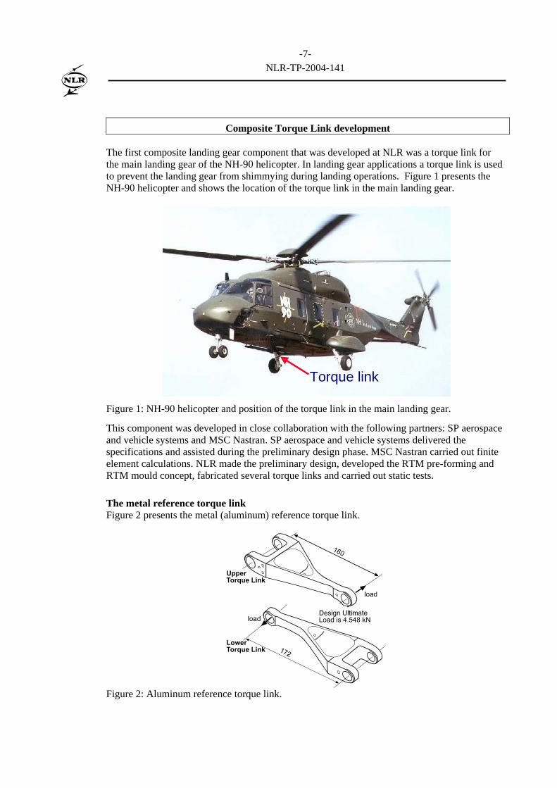
This component was developed in close collaboration with the following partners: SP aerospace and vehicle systems and MSC Nastran. SP aerospace and vehicle systems delivered the specifications and assisted during the preliminary design phase. MSC Nastran carried out finite element calculations. NLR made the preliminary design, developed the RTM pre-forming and RTM mould concept, fabricated several torque links and carried out static tests. The metal reference torque link Figure 2 presents the metal (aluminum) reference torque link.
Figure 2: Aluminum reference torque link.
-8-
NLR-TP-2004-141
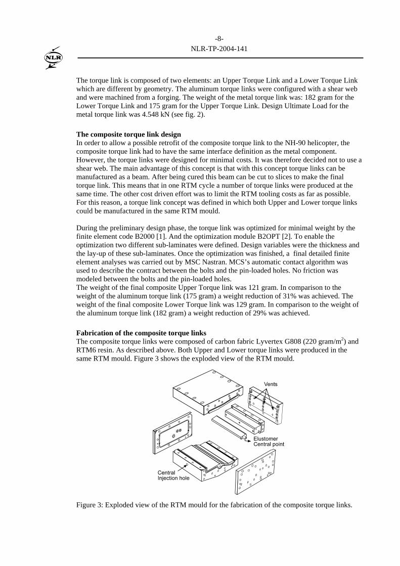
The torque link is composed of two elements: an Upper Torque Link and a Lower Torque Link which are different by geometry. The aluminum torque links were configured with a shear web and were machined from a forging. The weight of the metal torque link was: 182 gram for the Lower Torque Link and 175 gram for the Upper Torque Link. Design Ultimate Load for the metal torque link was 4.548 kN (see fig. 2). The composite torque link design In order to allow a possible retrofit of the composite torque link to the NH-90 helicopter, the composite torque link had to have the same interface definition as the metal component. However, the torque links were designed for minimal costs. It was therefore decided not to use a shear web. The main advantage of this concept is that with this concept torque links can be manufactured as a beam. After being cured this beam can be cut to slices to make the final torque link. This means that in one RTM cycle a number of torque links were produced at the same time. The other cost driven effort was to limit the RTM tooling costs as far as possible. For this reason, a torque link concept was defined in which both Upper and Lower torque links could be manufactured in the same RTM mould. During the preliminary design phase, the torque link was optimized for minimal weight by the finite element code B2000 [1]. And the optimization module B2OPT [2]. To enable the optimization two different sub-laminates were defined. Design variables were the thickness and the lay-up of these sub-laminates. Once the optimization was finished, a final detailed finite element analyses was carried out by MSC Nastran. MCS’s automatic contact algorithm was used to describe the contract between the bolts and the pin-loaded holes. No friction was modeled between the bolts and the pin-loaded holes. The weight of the final composite Upper Torque link was 121 gram. In comparison to the weight of the aluminum torque link (175 gram) a weight reduction of 31% was achieved. The weight of the final composite Lower Torque link was 129 gram. In comparison to the weight of the aluminum torque link (182 gram) a weight reduction of 29% was achieved. Fabrication of the composite torque links The composite torque links were composed of carbon fabric Lyvertex G808 (220 gram/m2) and RTM6 resin. As described above. Both Upper and Lower torque links were produced in the same RTM mould. Figure 3 shows the exploded view of the RTM mould.
Figure 3: Exploded view of the RTM mould for the fabrication of the composite torque links.
-9-
NLR-TP-2004-141
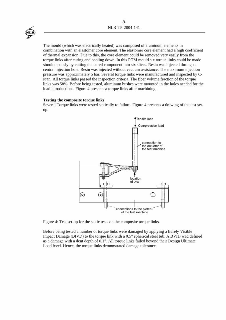
The mould (which was electrically heated) was composed of aluminum elements in combination with an elastomer core element. The elastomer core element had a high coefficient of thermal expansion. Due to this, the core element could be removed very easily from the torque links after curing and cooling down. In this RTM mould six torque links could be made simultaneously by cutting the cured component into six slices. Resin was injected through a central injection hole. Resin was injected without vacuum assistance. The maximum injection pressure was approximately 5 bar. Several torque links were manufactured and inspected by C-scan. All torque links passed the inspection criteria. The fiber volume fraction of the torque links was 58%. Before being tested, aluminum bushes were mounted in the holes needed for the load introductions. Figure 4 presents a torque links after machining. Testing the composite torque links Several Torque links were tested statically to failure. Figure 4 presents a drawing of the test set-up.
Figure 4: Test set-up for the static tests on the composite torque links. Before being tested a number of torque links were damaged by applying a Barely Visible Impact Damage (BIVD) to the torque link with a 0.5” spherical steel tub. A BVID wad defined as a damage with a dent depth of 0.1”. All torque links failed beyond their Design Ultimate Load level. Hence, the torque links demonstrated damage tolerance.
-10-
NLR-TP-2004-141
F-16 drag brace development
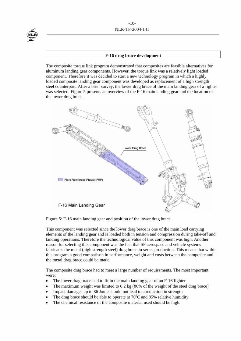
The composite torque link program demonstrated that composites are feasible alternatives for aluminum landing gear components. However, the torque link was a relatively light loaded component. Therefore it was decided to start a new technology program in which a highly loaded composite landing gear component was developed as replacement of a high strength steel counterpart. After a brief survey, the lower drag brace of the main landing gear of a fighter was selected. Figure 5 presents an overview of the F-16 main landing gear and the location of the lower drag brace.
Figure 5: F-16 main landing gear and position of the lower drag brace. This component was selected since the lower drag brace is one of the main load carrying elements of the landing gear and is loaded both in tension and compression during take-off and landing operations. Therefore the technological value of this component was high. Another reason for selecting this component was the fact that SP aerospace and vehicle systems fabricates the metal (high strength steel) drag brace in series production. This means that within this program a good comparison in performance, weight and costs between the composite and the metal drag brace could be made. The composite drag brace had to meet a large number of requirements. The most important were: • The lower drag brace had to fit in the main landing gear of an F-16 fighter • The maximum weight was limited to 6.2 kg (80% of the weight of the steel drag brace) • Impact damages up to 86 Joule should not lead to a reduction in strength • The drag brace should be able to operate at 700C and 85% relative humidity • The chemical resistance of the composite material used should be high.
-11-
NLR-TP-2004-141
The metal lower drag brace is configured as an I-shaped beam. For the conceptual design of the composite drag brace the box girder concept was selected. This concept was selected since a box girder has a limited number of free edges that are sensitive to impact damages, hence increasing the damage tolerance of the drag brace. The composite drag brace was configured with three lugs: two to enable the rotation of the component during take-off and landing of the aircraft and one for connecting a locking device. The middle of the drag brace was tapered in order to meet the interface requirements of the main landing gear. The RTM fabrication method was selected to produce the composite drag brace. This fabrication concept was selected because with RTM complex shaped components can be made within very tight outer dimensional tolerances. Since at the moment the conceptual design was made no design allowable of the materials used were at hand, the conceptual design was based on assumed design allowable. Materials used and material properties For fiber reinforcements the following Non Crimped Fabrics (NCF) were selected: • [+450, -450], 705 gram/m2 and IM-7 (12 k) fibers • [00, 900], 817 gram/m2 and IM-7 (12 k) fibers. Before being processed to a pre-form the NCF’s were bindered with binder powder Cycom 790. The resin Cycom 890 was selected for its compatibility with the binder powder and its excellent mechanical properties and glass transition temperature Tg wet of 169 0C. In order to determine design allowable a limited material qualification program was carried out by testing coupons of one batch of NCF’s and one batch of resin. The results of the material qualification program were transferred to B-basis values. Coupon tests were carried out at ambient and hot/wet (700C and 85% relative humidity) conditions. In order to determine the chemical resistance, Interlaminar Shear tests were carried out on specimens that had been exposed to white spirit, turbo clean, kilfrost, JP-8 and several hydraulic oils for a period of 1000 hours. The allowable average design strain level was determined by testing Open Hole Compression (OHC) specimens at ambient as well as cold dry (-55 0C) and hot/wet conditions (700C and 85% relative humidity). The OHC specimens had the same lay-up as the lay-up that was defined during the conceptual design of the drag brace. This allowable design strain level should ensure the load carrying capability of the drag brace after being damaged by an impact. Detailed design After the design allowable were determined the detailed design was made. The detailed design was made by carrying out finite element calculations for which B2000 was used. B2000 is NLR’s test bed for computational structural mechanics. The finite element model was composed of four nodes Stanley-type shell elements. The optimization module B2OPT within B2000 was used to optimize the composite drag brace for minimal weight with maximum values for the strains and displacements as constraints. In order to facilitate the optimization laminate design variables were defined. The means that the number of 00/900 NCF and +450/-450 NCF layers varied during the optimization leading to an optimal laminate. The Tsai-Hill failure criterion was used as a failure criterion. The optimum was found after 12 optimization cycles. After completion of the optimization a buckling analyses was carried out. The fist buckling mode had an eigenvalue of 4.05. The weight of the optimized composite drag brace was 4.7 kg which is a reduction of 39% in comparison to the steel lower drag brace. The lugs were not modeled in detail since this would increase the complexity of the model. The load carrying capability of the
-12-
NLR-TP-2004-141
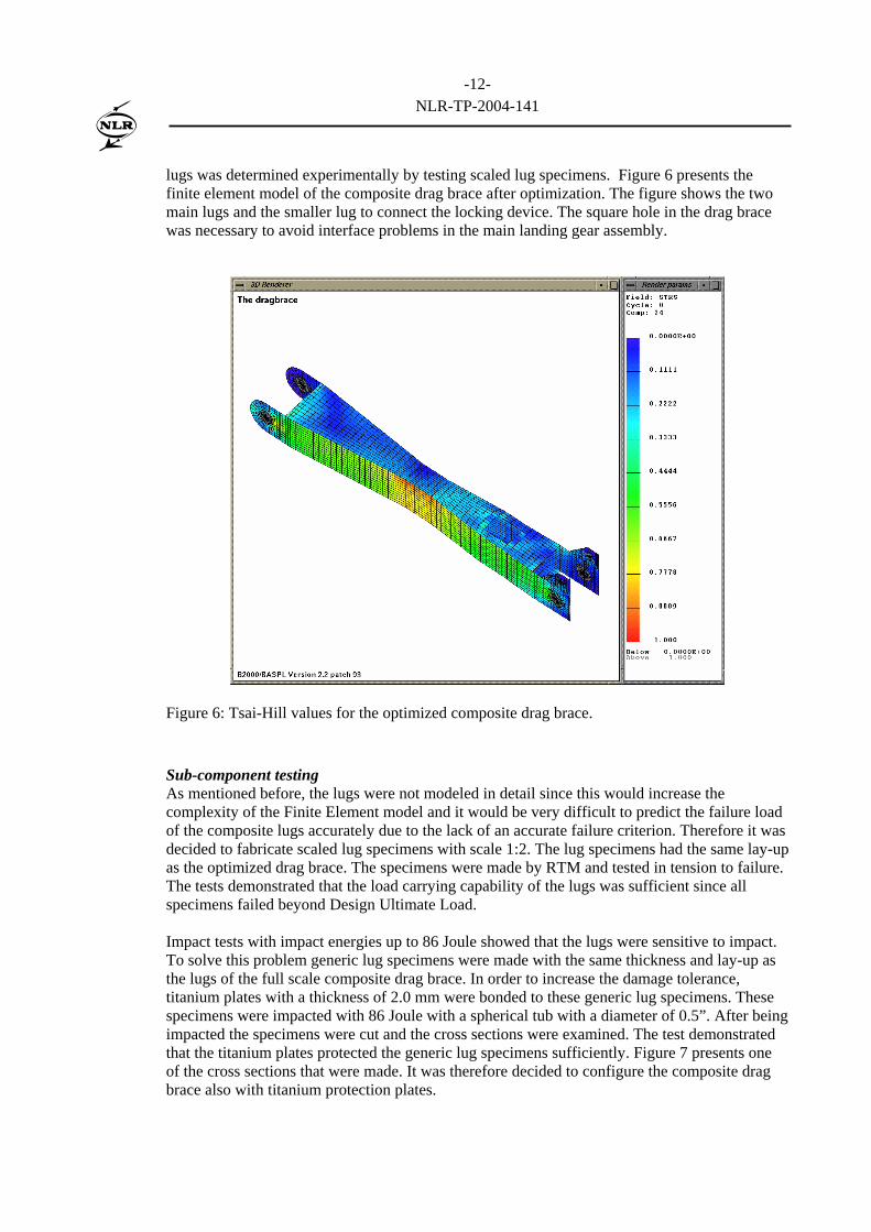
lugs was determined experimentally by testing scaled lug specimens. Figure 6 presents the finite element model of the composite drag brace after optimization. The figure shows the two main lugs and the smaller lug to connect the locking device. The square hole in the drag brace was necessary to avoid interface problems in the main landing gear assembly.
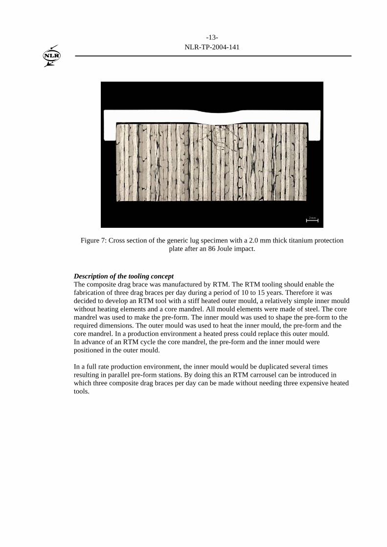
Figure 6: Tsai-Hill values for the optimized composite drag brace. Sub-component testing As mentioned before, the lugs were not modeled in detail since this would increase the complexity of the Finite Element model and it would be very difficult to predict the failure load of the composite lugs accurately due to the lack of an accurate failure criterion. Therefore it was decided to fabricate scaled lug specimens with scale 1:2. The lug specimens had the same lay-up as the optimized drag brace. The specimens were made by RTM and tested in tension to failure. The tests demonstrated that the load carrying capability of the lugs was sufficient since all specimens failed beyond Design Ultimate Load. Impact tests with impact energies up to 86 Joule showed that the lugs were sensitive to impact. To solve this problem generic lug specimens were made with the same thickness and lay-up as the lugs of the full scale composite drag brace. In order to increase the damage tolerance, titanium plates with a thickness of 2.0 mm were bonded to these generic lug specimens. These specimens were impacted with 86 Joule with a spherical tub with a diameter of 0.5”. After being impacted the specimens were cut and the cross sections were examined. The test demonstrated that the titanium plates protected the generic lug specimens sufficiently. Figure 7 presents one of the cross sections that were made. It was therefore decided to configure the composite drag brace also with titanium protection plates.
-13-
NLR-TP-2004-141
Figure 7: Cross section of the generic lug specimen with a 2.0 mm thick titanium protection plate after an 86 Joule impact.
Description of the tooling concept The composite drag brace was manufactured by RTM. The RTM tooling should enable the fabrication of three drag braces per day during a period of 10 to 15 years. Therefore it was decided to develop an RTM tool with a stiff heated outer mould, a relatively simple inner mould without heating elements and a core mandrel. All mould elements were made of steel. The core mandrel was used to make the pre-form. The inner mould was used to shape the pre-form to the required dimensions. The outer mould was used to heat the inner mould, the pre-form and the core mandrel. In a production environment a heated press could replace this outer mould. In advance of an RTM cycle the core mandrel, the pre-form and the inner mould were positioned in the outer mould. In a full rate production environment, the inner mould would be duplicated several times resulting in parallel pre-form stations. By doing this an RTM carrousel can be introduced in which three composite drag braces per day can be made without needing three expensive heated tools.
-14-
NLR-TP-2004-141
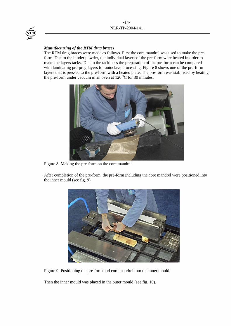
Manufacturing of the RTM drag braces The RTM drag braces were made as follows. First the core mandrel was used to make the pre-form. Due to the binder powder, the individual layers of the pre-form were heated in order to make the layers tacky. Due to the tackiness the preparation of the pre-form can be compared with laminating pre-preg layers for autoclave processing. Figure 8 shows one of the pre-form layers that is pressed to the pre-form with a heated plate. The pre-form was stabilised by heating the pre-form under vacuum in an oven at 120 0C for 30 minutes.
Figure 8: Making the pre-form on the core mandrel. After completion of the pre-form, the pre-form including the core mandrel were positioned into the inner mould (see fig. 9)
Figure 9: Positioning the pre-form and core mandrel into the inner mould. Then the inner mould was placed in the outer mould (see fig. 10).
-15-
NLR-TP-2004-141
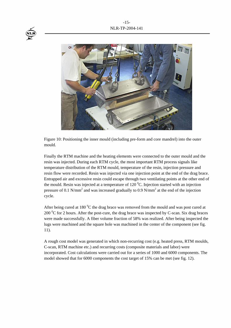
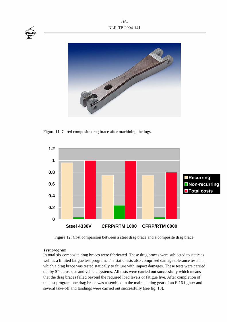
Figure 10: Positioning the inner mould (including pre-form and core mandrel) into the outer mould. Finally the RTM machine and the heating elements were connected to the outer mould and the resin was injected. During each RTM cycle, the most important RTM process signals like temperature distribution of the RTM mould, temperature of the resin, injection pressure and resin flow were recorded. Resin was injected via one injection point at the end of the drag brace. Entrapped air and excessive resin could escape through two ventilating points at the other end of the mould. Resin was injected at a temperature of 120 0C. Injection started with an injection pressure of 0.1 N/mm2 and was increased gradually to 0.9 N/mm2 at the end of the injection cycle. After being cured at 180 0C the drag brace was removed from the mould and was post cured at 200 0C for 2 hours. After the post-cure, the drag brace was inspected by C-scan. Six drag braces were made successfully. A fiber volume fraction of 58% was realized. After being inspected the lugs were machined and the square hole was machined in the center of the component (see fig. 11). A rough cost model was generated in which non-recurring cost (e.g. heated press, RTM moulds, C-scan, RTM machine etc.) and recurring costs (composite materials and labor) were incorporated. Cost calculations were carried out for a series of 1000 and 6000 components. The model showed that for 6000 components the cost target of 15% can be met (see fig. 12).
-16-
NLR-TP-2004-141
Figure 11: Cured composite drag brace after machining the lugs.
0
0.2
0.4
0.6
0.8
1
1.2
Steel 4330V CFRP/RTM 1000 CFRP/RTM 6000
RecurringNon-recurringTotal costs
Figure 12: Cost comparison between a steel drag brace and a composite drag brace.
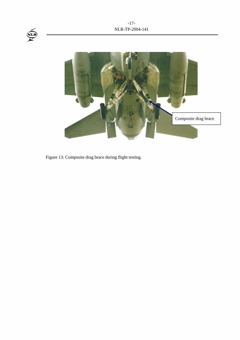
Test program In total six composite drag braces were fabricated. These drag braces were subjected to static as well as a limited fatigue test program. The static tests also comprised damage tolerance tests in which a drag brace was tested statically to failure with impact damages. These tests were carried out by SP aerospace and vehicle systems. All tests were carried out successfully which means that the drag braces failed beyond the required load levels or fatigue live. After completion of the test program one drag brace was assembled in the main landing gear of an F-16 fighter and several take-off and landings were carried out successfully (see fig. 13).
-17-
NLR-TP-2004-141
Figure 13: Composite drag brace during flight testing.
Composite drag brace
-18-
NLR-TP-2004-141
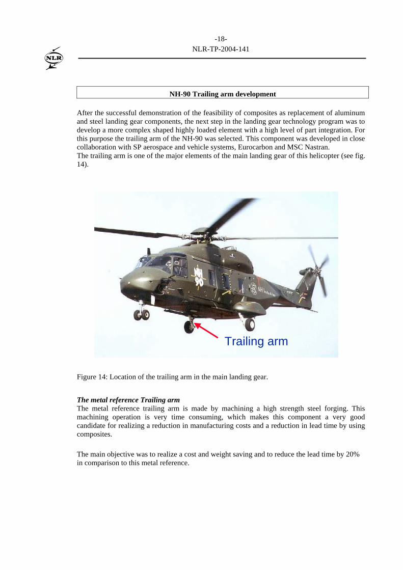
NH-90 Trailing arm development After the successful demonstration of the feasibility of composites as replacement of aluminum and steel landing gear components, the next step in the landing gear technology program was to develop a more complex shaped highly loaded element with a high level of part integration. For this purpose the trailing arm of the NH-90 was selected. This component was developed in close collaboration with SP aerospace and vehicle systems, Eurocarbon and MSC Nastran. The trailing arm is one of the major elements of the main landing gear of this helicopter (see fig. 14).
Trailing arm
Figure 14: Location of the trailing arm in the main landing gear. The metal reference Trailing arm The metal reference trailing arm is made by machining a high strength steel forging. This machining operation is very time consuming, which makes this component a very good candidate for realizing a reduction in manufacturing costs and a reduction in lead time by using composites. The main objective was to realize a cost and weight saving and to reduce the lead time by 20% in comparison to this metal reference.
-19-
NLR-TP-2004-141
The composite trailing arm concept The composite trailing arm assembly consists of a tubular braided element, two composite tubes with bronze bushings, a central lug made of fabric and a steel wheel axle (see fig. 15).
Drawing by SP aerospace andvehicle systems
Bronze bushing
Braid
Fabric pre-formfor the lugs
Steel wheel axle
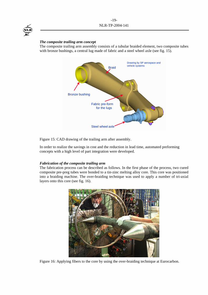
Figure 15: CAD drawing of the trailing arm after assembly. In order to realize the savings in cost and the reduction in lead time, automated preforming concepts with a high level of part integration were developed. Fabrication of the composite trailing arm The fabrication process can be described as follows. In the first phase of the process, two cured composite pre-preg tubes were bonded to a tin-zinc melting alloy core. This core was positioned into a braiding machine. The over-braiding technique was used to apply a number of tri-axial layers onto this core (see fig. 16).
Figure 16: Applying fibers to the core by using the over-braiding technique at Eurocarbon.
-20-
NLR-TP-2004-141
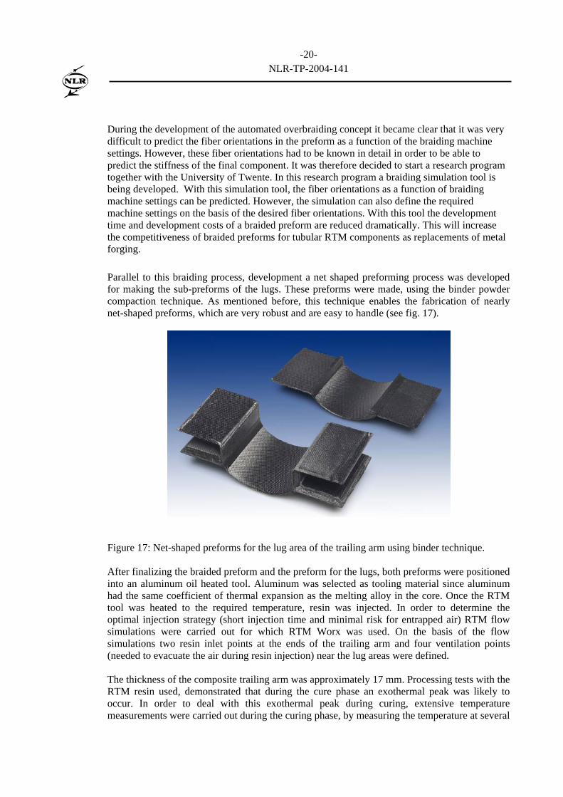
During the development of the automated overbraiding concept it became clear that it was very difficult to predict the fiber orientations in the preform as a function of the braiding machine settings. However, these fiber orientations had to be known in detail in order to be able to predict the stiffness of the final component. It was therefore decided to start a research program together with the University of Twente. In this research program a braiding simulation tool is being developed. With this simulation tool, the fiber orientations as a function of braiding machine settings can be predicted. However, the simulation can also define the required machine settings on the basis of the desired fiber orientations. With this tool the development time and development costs of a braided preform are reduced dramatically. This will increase the competitiveness of braided preforms for tubular RTM components as replacements of metal forging. Parallel to this braiding process, development a net shaped preforming process was developed for making the sub-preforms of the lugs. These preforms were made, using the binder powder compaction technique. As mentioned before, this technique enables the fabrication of nearly net-shaped preforms, which are very robust and are easy to handle (see fig. 17).
Figure 17: Net-shaped preforms for the lug area of the trailing arm using binder technique. After finalizing the braided preform and the preform for the lugs, both preforms were positioned into an aluminum oil heated tool. Aluminum was selected as tooling material since aluminum had the same coefficient of thermal expansion as the melting alloy in the core. Once the RTM tool was heated to the required temperature, resin was injected. In order to determine the optimal injection strategy (short injection time and minimal risk for entrapped air) RTM flow simulations were carried out for which RTM Worx was used. On the basis of the flow simulations two resin inlet points at the ends of the trailing arm and four ventilation points (needed to evacuate the air during resin injection) near the lug areas were defined. The thickness of the composite trailing arm was approximately 17 mm. Processing tests with the RTM resin used, demonstrated that during the cure phase an exothermal peak was likely to occur. In order to deal with this exothermal peak during curing, extensive temperature measurements were carried out during the curing phase, by measuring the temperature at several
-21-
NLR-TP-2004-141
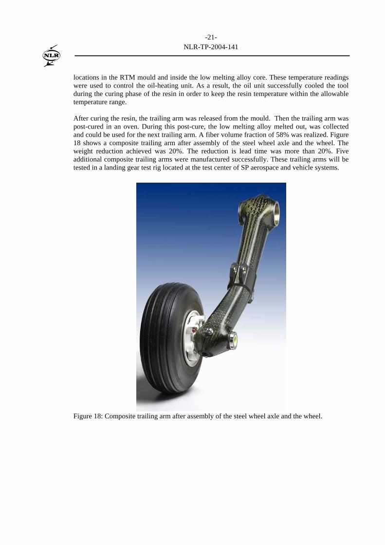
locations in the RTM mould and inside the low melting alloy core. These temperature readings were used to control the oil-heating unit. As a result, the oil unit successfully cooled the tool during the curing phase of the resin in order to keep the resin temperature within the allowable temperature range. After curing the resin, the trailing arm was released from the mould. Then the trailing arm was post-cured in an oven. During this post-cure, the low melting alloy melted out, was collected and could be used for the next trailing arm. A fiber volume fraction of 58% was realized. Figure 18 shows a composite trailing arm after assembly of the steel wheel axle and the wheel. The weight reduction achieved was 20%. The reduction is lead time was more than 20%. Five additional composite trailing arms were manufactured successfully. These trailing arms will be tested in a landing gear test rig located at the test center of SP aerospace and vehicle systems.
Figure 18: Composite trailing arm after assembly of the steel wheel axle and the wheel.
-22-
NLR-TP-2004-141
Conclusions
Several technology programs were carried out successfully by a collaboration between industries, research establishments and universities. The programs demonstrated that RTM can be used as fabrication method for making complex shaped damage tolerant landing gear components with a high level of part integration. . By using composites in stead of steel large weight saving can be obtained. For large series also cost savings are feasible. Based on the results of the technology programs described in this paper, the conclusion can be drawn that composite landing gear components are feasible cost-effective alternatives for steel landing gear components. Composite landing gear components therefore are opportunities to be taken for application in the next generation civil and military aircraft.
-23-
NLR-TP-2004-141
References
1. Modular Finite Element Analysis Tools applied to problems in Engineering, Phd These no.
1251, Ecole Plythenique Federale de lausanne, by Silvio Merazzi, lausanne, EPFL 1994. 2. The B2000 Optimisation Module: B2OPT, by P. Arendsen, NLR TP 94116 L, Published as
part of the GARTEUR AG13 “Structural Optimisation” action group report, March 1993.
Biography Name: Bert Thuis Date of Birth: 04-11-1965 Masters in Aerospace Engineering at the Technical University of Delft in 1990 From 1990 – 2000 Research Engineer at the Structures Department of NLR Activities: • Design of post-buckled composite skin panels • Design of composite landing gear components • Development of RTM and autoclave fabrication concepts for composite structures • Project manager of the certification test on the Fokker 100 full scale composite horizontal
tail plane From 2000 – 2003 Group Manager of the Development and Evaluation group within the Structures Department From 2004 – Head Structures Technology Department within the Aerospace and Vehicles Division of NLR.