Embed Size (px)
Citation preview

THE DISTRIBUTOR TEST MACHINE for 25D and
45D series distributors:
Dr. H. Holden Jan 2015.
Introduction:
The machine shown above was constructed to test 25D and 45D Lucas distributors and their
variations such as the 45DM4. It allows the RPM related advance to be plotted. Both the RPM
and advance can be displayed either in engine degrees or distributor degrees on the central angle
meter and rpm meter on the upper right. The left hand meter is a Dwell meter. The inputs to the
machine can either be contact breaker style or reluctor style signals, or signals from magnet &
Hall device switching amplifier systems used as “distributor inserts” sold as distributor upgrades
to eliminated contact breakers.
The machine is powered by a Hitachi 3 Phase variable frequency drive unit and a 0.18kW three
phase motor. Vacuum is manually supplied to the distributor’s vacuum unit via a syringe and

vacuum meter to document the vacuum advance or retard. The machine has the capability to
drive ignition coils directly or it can be coupled to the author’s Spark Energy Test Machine (see
www.worldphaco.net) for more spark energy recordings.
Machine design & construction:
The drive from the motor is belt coupled to a driveshaft which uses a Pertronix distributor
module as a “shaft encoder” so as to measure the angle of the driving shaft:
The photo below shows the machine’s general construction. The custom designed control
circuitry mounts immediately beside the VFD:

At the core of the machine is the Phase Detector Circuit. This circuit measures the angle or phase
difference between the distributor’s drive shaft and the output from the contact breaker, reluctor
or other encoding device in the distributor under test (DUT). The result is displayed on the
central meter in degrees of distributor rotation or degrees of what would be engine crankshaft
rotation, whatever is selected on the machine’s control panel. The diagram below shows how the
phase detector and phase meter are configured. It is base on an S-R flip flop reset by
narrow(50uS) pulses. The reason that this system was used is that this detector is very resistant to
errors cause by mechanical jitter on the signal and responds with a specific polarity output with
respect to its input signals and that the two input channels are unique (unlike an XOR based
phase detector). Also the phase detector’s output is filtered with a 1.5 second time constant to
give very stable meter readings despite any mechanical jitter:
Since the Distributor Under Test (DUT) signal can originate from a mechanical source (the
contact breaker) this channel has some addition de-bounce components.(note in the schematics
drawn here any crossing wires are not connected)

The schematic below shows the general circuitry.
Since the phase detector will have a large offset when there is no distributor rotation, a rotation
detector is used to zero the meter when the machine is powered but not in operation. In addition,
since some distributors have vacuum retard, the phase meter can be reversed by front panel
selection.

The Reluctor amplifier signal (if present) and the contact breaker signal are simply OR’d to
become the DUT signal. The reluctor processing amplifier is shown below:
The Dwell meter which monitors the DUT is very straightforward and the display (meter) zeros
automatically with no distributor rotation:

RESULTS:
The following data was obtained testing distributors 45DM4. These had various vacuum units
attached:
The vacuum advance on the 25D distributor could not be tested because its diaphragm was
perforated. The 25D otherwise closely matched the published specifications. The vacuum units
were tested on the machine with a precision vacuum meter ad the results were close to the
markings:
Vacuum Unit :
3-11-12 tested: (3.9)-(10.2)-(10.0)
6-13-6 tested: (7.3)-(14.8)- (5.75)
10-15-5 tested: (8.7)-(14.2)-(5.5)
Unmarked unit fitted to -1182 45DM4: tested: (2.9)-(11.0)-(7.0) so is probably a 3-11-7 unit.
UTILITY OF THE DISTRIBUTOR TEST MACHINE & HEI testing:
Apart from being able to test distributors to determine the RPM and vacuum related advance
characteristics, the machine is useful for running up reluctor style distributors and testing them
with the type of amplifier/switching system that the manufacturer of the system designed. In this
type of distributor the signal generated is unique and its voltage-time profile combined with the
type of switching amplifier that it drives determines the dwell.
For example with a simple threshold switching amplifier the dwell at low RPM is around 20
degrees, and at high RPM around 45 degrees from a typical reluctor. However in the HEI system
(based on Motorola’s MC3334 IC) where there is bidirectional dwell control, the results are quite
different.
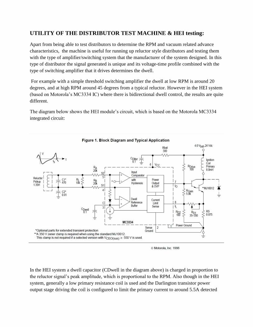
The diagram below shows the HEI module’s circuit, which is based on the Motorola MC3334
integrated circuit:
In the HEI system a dwell capacitor (CDwell in the diagram above) is charged in proportion to
the reluctor signal’s peak amplitude, which is proportional to the RPM. Also though in the HEI
system, generally a low primary resistance coil is used and the Darlington transistor power
output stage driving the coil is configured to limit the primary current to around 5.5A detected

across resistor RS. However at the time this current limiter deploys, the dwell capacitor is
discharged. The HEI system enables current control of the coil at low rpm to prevent overheating
and at the same time maximum coil output and spark energy at high RPM because the dwell is
optimized to the maximum available time leaving about 1mS time for the actual spark itself. (See
notes below in “Discussion” for what can happen if the coil primary resistance is so high as to
not initiate the current limiter in the HEI unit and see notes below in “Discussion” about what
can happen if the coil primary resistance is too low.)
With low R primary ignitions coils (between 0.5R to 1.5R) the HEI system delivers nearly a
constant spark energy output across the full RPM range, though it always falls in the higher RPM
range because there is not enough time for the coil current to reach the 5.5A threshold. The
Lucas version of this system, fitted to MG Midgets, Triumph Spitfires, TR7’s and other British
cars such as Jaguars was called CEI (Constant Energy Ignition).
The Lucas CEI modules of the early 1980’s actually have the GM HEI module inside them
which is based on Motorola’s MC3334 IC. With a 1.5R coil the spark energy is excellent also,
despite a small reduction at the high RPM end however it is still twice as good as standard
Kettering.
The photo below is a simultaneous recording of the reluctor voltage and the ignition coil’s
primary voltage with an HEI module and a 1.5R primary resistance ignition coil. It is a low rpm
recording (around 1200 rpm) and it is easy to see on the waveform when the HEI’s current
limiter activates for about 33% of the operating cycle. During this time the amount of heat
generated in the module is significantly increased:

The following graph is a spark energy recording (mJ per spark) of a reluctor driven 45DM4 HEI
system with the Bosch GT40RT (1.5Ohm) transformer ignition coil and the Bosch MEC723A
which is a 1.1 Ohm primary transformer coil similar to the GT40RT. The standard Kettering
system energies measured for a typical 3 Ohm ignition oil style coil and for a 3 Ohm transformer
style coil is shown in blue and green & pink for comparison:
(Of note: The above graphs also shows that simply going from a standard oil coil to a
transformer version of a standard 3 Ohm ignition coil, in the Kettering system, results in an
improvement in spark energy at the low rpm range only due to the higher primary inductance and
therefore more stored energy if the coil current profile has time to level off. However less spark
energy at the high rpm range because the transformer coil has a higher primary inductance and
therefore its L/R ratio or “time constant” is a little longer than the standard oil style coil and the
current doesn’t climb to a very high value per cycle prior to the spark)
The spark energy results for standard Kettering (60 Degrees dwell) and a standard 3 R primary
coils are above shown in blue & green, with the GT40RT (1.5 ohm coil) operating in standard
Kettering with the recommended 1.5 Ohm ballast resistor, so as to compare these with the HEI
recordings. These “standard Kettering spark energy results” are nearly exactly the same as for
electronically assisted Kettering, such as with a distributor insert with rotating magnets, or a

contact breaker with a transistor amplifier, although sometimes the energy can in fact be even
little lower with the inserts because the output transistor in them, typically a Darlington, has
about a 1 volt voltage drop which is higher than a contact breaker’s voltage drop. For this reason
some manufacturers have gone to an IGBT output stage device or a Mosfet in their distributor
inserts to get the result as least as good as the contact breaker. Despite these facts, distributor
insert marketing often claims “high energies” & powerful sparks. In fact the spark energy is
determined by the type of ignition coil and its primary current prior to magnetic field collapse
(all other things such as dwell and coil inductance being equal) and not the device or distributor
insert switching the coil on & off which doesn’t contribute to the spark energy at all unless there
is some dwell manipulation involved as there is in the HEI system.
The other advantage of the HEI system, apart from the higher spark energies is that with no
distributor rotation the ignition coil is in the OFF condition, which saves a lot of coil heating if
the ignition switch is left on without the engine running.
The photo below shows the inside of the 1982 vintage Lucas LUCAS CEI system amplifier
module type AB14. It uses GM’s HEI module, with an additional 1uF filter capacitor on its 12V
supply feed and a power zener diode on the HEI’s coil connection. This diode snubs of the peak
voltage to 350V (otherwise it is around about 450V which is a threat to the Darlington output
transistor in the module):
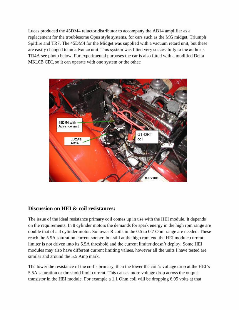
Lucas produced the 45DM4 reluctor distributor to accompany the AB14 amplifier as a
replacement for the troublesome Opus style systems, for cars such as the MG midget, Triumph
Spitfire and TR7. The 45DM4 for the Midget was supplied with a vacuum retard unit, but these
are easily changed to an advance unit. This system was fitted very successfully to the author’s
TR4A see photo below. For experimental purposes the car is also fitted with a modified Delta
MK10B CDI, so it can operate with one system or the other:
Discussion on HEI & coil resistances:
The issue of the ideal resistance primary coil comes up in use with the HEI module. It depends
on the requirements. In 8 cylinder motors the demands for spark energy in the high rpm range are
double that of a 4 cylinder motor. So lower R coils in the 0.5 to 0.7 Ohm range are needed. These
reach the 5.5A saturation current sooner, but still at the high rpm end the HEI module current
limiter is not driven into its 5.5A threshold and the current limiter doesn’t deploy. Some HEI
modules may also have different current limiting values, however all the units I have tested are
similar and around the 5.5 Amp mark.
The lower the resistance of the coil’s primary, then the lower the coil’s voltage drop at the HEI’s
5.5A saturation or threshold limit current. This causes more voltage drop across the output
transistor in the HEI module. For example a 1.1 Ohm coil will be dropping 6.05 volts at that

current, leaving 14-6.05 = 7 .95 volts across the HEI’s transistor output stage and dissipating
7.95 x 5.5 x 0.3 =13 Watts in the HEI module assuming say at the low rpm range the current
limiting was occurring for about 1/3 of the operating cycle as shown in the above recording. The
heat dissipation (in the module) is lower with a higher resistance primary coil.
So going to a lower resistance primary coil in the HEI system (in the low rpm range where the
HEI’s current limiter is active) shifts heat dissipation from the ignition coil to the HEI module.
For example the HEI module will run a little hotter in the low rpm range with the 1.1R
MEC723A coil than the 1.5R GT40RT coil. But as seen from the graph the MECH 723A gives a
little more spark energy than the GT40RT.
So it is very important that the HEI module is attached to a good heat radiating metal surface
with ample heat conducting compound. It should be noted that when Motorola designed the
MC3334 IC, it was for use with a separate transistor in a TO-3 package, such as an MJ10014 or
MJ10012, on a good heat sink. In the HEI module this transistor die has been fitted inside, along
with the IC and the supports resistors & capacitors. All of these parts get heated by the
transistor’s dissipation.
It is probable that some of the failures experienced with HEI modules therefore are a
combination of using low primary resistance coils, in the range of 0.5 to 0.7 Ohms in conjunction
with poor or inadequate HEI module heat sinking.
Also there are some interesting things that can happen if the ignition coil resistance is such that it
is high enough on its own, such as a 3 Ohm primary coil. The maximum current they can achieve
is 14/3 =4.66 amps. Therefore the current limiter in the HEI module does not reach its 5.5A
operating threshold. It depends on the particular module what happens here. Earlier 1980’s
vintage modules I have tested continue to operate. But the newer ones drop output of operation
in the low rpm range. This occurs because the charge on the dwell capacitor becomes excessive
and since the current limiter is not activating, there is no effect to discharge the capacitor, so the
input op amp in the IC gets biased out of conduction. So it appears some of the newer HEI clone
modules, and clone MC3334 IC’s inside them, require that the primary ignition coil resistance is
at least low enough to operate the current limiter which, if 5.5A, would mean that the coil would
have to have a primary resistance lower than about 2.5 Ohms or the newer clone HEI modules
will malfunction.

Conclusion about reluctor-HEI vs other MDI systems:
It should be pointed out that all the data I have acquired about a combination of a reluctor driven
HEI system is clear & conclusive. With a reluctor –HEI system it is possible to attain four very
important things which substantially improve spark energies:
1) Excellent bidirectional Dwell Control.
2) Low RPM coil current control and reduced coil heating.
3) Significantly higher spark energy output compared to a conventional Kettering system
or any system with a fixed switching signal derived from the distributor, such as rare earth
magnets & Hall devices common in aftermarket “distributor inserts” or an Optical sensor
systems. This is especially so in the higher RPM ranges.
4) Freedom from coil overheating with the ignition left on and engine not running.
It is the unique nature of the reluctor’s signal combined with the processing by the MC3334 IC
which allows the above features. The reluctor’s signal amplitude, being an AC generator, is
proportional to the rpm and it is this unique feature of the reluctor as a distributor “shaft
encoder” in conjunction with Motorola’s MC3334 IC which allows the above functions to be
possible.
The signals derived from the magnets & Hall switch sensors in distributor inserts, or optical
distributors do not contain amplitude information related to the RPM, they only contain timing or
switching 0n-0ff information, and this severely limits their performance compared to reluctor
driven HEI. The signals detected by Hall devices are proportional to the magnetic field strength,
so they are useful as an angle or on-off position sensors, whereas the voltages generated by a
reluctor are proportional to the rate of change of the magnetic flux and so their amplitude is
dependent on the rpm and this information can be used, as it is in the HEI system, for dwell
control. It would be possible to build a unique type of Hall sensor input system (distributor shaft
encoder) where the Hall sensor signal was linear and electronically differentiated to gain the rpm
related information required for dwell control, to achieve similar results to HEI. However dwell
control is only part of the HEI system, there is also the need for coil current limiting in the low
rpm range and this is a heat dissipative process with over 10 watts to dissipate. The distributor
inserts already appear to have heat dissipation issues affecting their reliability and adding the
HEI style 5.5A current limiter to their internal design would aggravate this issue and probably
make them even less reliable.
Therefore the reluctor-HEI system completely trumps standard Kettering, Optical or Hall –
magnetic detector systems or distributor insert systems (replacing contact breakers) for spark
energy.

Some distributor inserts on Ebay are now claiming to have “dwell control” I have yet to test any.
If they were effective they would also require as noted above, in addition to the claimed dwell
control, have coil over-current control and be designed for use with low R primary coils without
series coil resistors to achieve results similar to reluctor-HEI and in that case also be able to
handle over 10watts of thermal dissipation which is a highly unlikely scenario in my view.
Reluctor-HEI also trumps CDI systems for spark energy, although the spark energy is delivered
in a shorter time with CDI (typically around 150uS vs 1.5mS) and CDI has higher peak spark
currents than MDI systems. The effect of this on fuel combustion is open to conjecture, but a
CDI system is more complicated than HEI and has higher component stressors.
If you are stuck with a non reluctor style distributor, then CDI is advantageous as it ignores the
dwell issue and has uniform, although much lower spark energy (typically 10 to 20mJ/spark)
across the full RPM range. The spark energy value depending on the type of ignition coil used
(Standard Oil type or Transformer type) and the values and charging voltages of the discharge
capacitor (typically 1.5uF & 400V) and the recharging capacity of the CDI’s DC:DC converter.
If you plan to move to a reluctor style distributor for your TR car be aware that there are
basically two types of 45DM4’s. Although they have the same mechanical features, some have a
different reluctor coil with a low resistance & inductance compared to the type needed to drive
the HEI module. These have about 8” leads exiting the distributor not 4.5” ones, so they are
fairly easily recognized and from the distributor numbers:

Calculations indicate that the low R and Low L unit was wound with thicker wire and 1/3 the
number of turns to fill the coil bobbin (it is not a faulty unit with shorted turns). Presumably the
low R and low L reluctor drove a different type of switching amplifier designed by Lucas and
not GM’s HEI module containing the MC3334 IC.
Without spring and weight modifications, some types of 45DM4 are not suited to the TR4
especially if they have high value vacuum advance units on them.
*****************************************************************************