Embed Size (px)
Citation preview
1
The Effect of Flow Rate on the Preferential Weld Corrosion of X65 Pipeline Steel
N. Nofrizal
1,2, M. J. Robinson
1 and S. A. Impey
1,
1Cranfield University, England
2Ministry of Energy and Mineral Resources, Indonesia
Email: [email protected]; [email protected]; [email protected]*
Abstract
Large galvanic currents occurring in a weld between the parent metal, weld metal and heat affected
zone can sometimes lead to serious localised corrosion. In practice, the galvanic currents are generally
controlled by the addition of a corrosion inhibitor and by ensuring that the composition of the weld
metal is selected to make it slightly more noble than the parent material. However, it has been shown
that in some circumstances, a current reversal takes place which results in the weld metal becoming
more active than the parent metal and severe attack of the weld occurs. The corrosion inhibitor
appears to have a role in this current reversal. It has been proposed that the inhibitor may be
selectively removed from the weld metal at the high flow rate but this needs further investigation.
The aim of the research described in this paper is to study the effect of flow rate on preferential weld
corrosion in X65 pipeline steel by investigating the hydrodynamic conditions under which current
reversal takes place. A submerged jet-impingement flow loop was used to investigate the corrosion
behaviour of the steel in stagnant and flowing brine, saturated with CO2 at 1 bar. The galvanic currents
between the weldment samples in each hydrodynamic region were recorded simultaneously using
zero-resistance ammeters and analysed to investigate the impact of galvanic effects on the overall
corrosion rate.
Key words: Preferential weld corrosion; carbon dioxide; electrochemical measurements; submerged
jet impingement
*Correspondence Author
1. Introduction
Preferential weld corrosion (PWC) is a serious form of attack in which the corrosion rates of
the weld metal (WM) and heat affected zone (HAZ) exceed that of the parent metal (PM).
Figure 1 shows an example of severe PWC in a carbon steel pipeline which failed after only a
few months in service [1].
2
Figure 1. Severe PWC in carbon steel pipeline in oil and gas systems [1]
Preferential weld corrosion occurs by a galvanic corrosion mechanism caused by differences
in the composition and microstructure of the metal in the three weld regions [2]. It can be
controlled by alloying the weld metal so that it is slightly cathodic to the parent metal and
therefore benefits from partial corrosion protection [3]. In addition, oilfield corrosion
inhibitors, which operate by adsorbing onto the metal surface, are an effective way of
reducing the corrosion rate to acceptable levels [4]. However, inhibitor adsorption is affected
by the flow rate of the fluid in the pipeline. It has been shown that at high flow rates a current
reversal can take place, with the weld metal changing from being more cathodic than the
parent metal to being more anodic, and severe PWC results. This attack is exacerbated by the
now large cathodic area of the parent metal, relative to the small area of the anodic weld
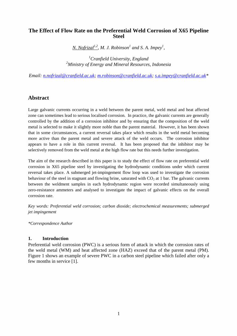
metal. Figure 2 shows galvanic currents measured in rotating electrode studies of a X65
pipeline steel weldment tested in inhibited brine containing CO2 [5]. The current reversals that
occurred first at 4000rpm and again at 5000rpm are thought to be caused by the inhibitor
being removed selectively by the flow from different regions of the weld in turn.
Figure 2. Galvanic currents in a X65 steel weldment in inhibited brine containing CO2
displaying current reversals at 4000 and 5000 rpm [5, 6]
3
This important finding needs further investigation and the aim of the work described in this
paper is to investigate in detail the influence of fluid flow on current reversal. A new weld is
being studied, having been produced by a different process and using different welding
parameters from those employed in previous work [7]. The paper describes progress in this
current research project to date.
2. Experimental Procedure
Materials
A Submerged Jet Impingement (SJI) target was prepared from a sample of X65 pipeline steel
with a weldment from a multi-pass welding process. The chemical composition of the parent
metal and weld metal is shown in Table 1.
Table 1. Composition of X65 pipeline steel (I) and weld metal (II) (Wt %)
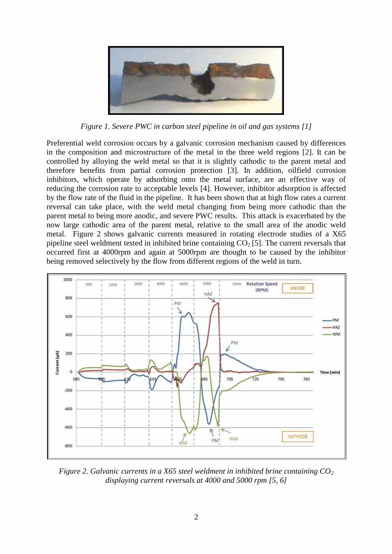
The weldment plate (Figure 3), of area 210 x 60 mm2 and 30 mm thickness, was polished
using different grades of abrasive paper from 240 to 1200 grit, rinsed with deionized water,
isopropanol then etched in 10 % Nital. The detailed macrostructure of X65 weldment is
shown in Figure 3C with parent metal (PM), weld metal (WM) and heat affected zone (HAZ).
Figure 3. (A) Welded plate, (B) plate etched in 10 % Nital and (C) PM, WM and HAZ
macrostructure
C Si Mn P S N Al Cu Mo Ni Cr Nb Ti
Pipe (%) 0.07 0.30 1.51 0.01 <0.005 0.005 0.04 0.26 0.01 0.39 0.02 0.02 <0.01
Weld (%) 0.07 0.30 1.59 0.01 0.007 0.005 <0.01 0.1 0.11 0.27 0.03 <0.01 <0.01
4
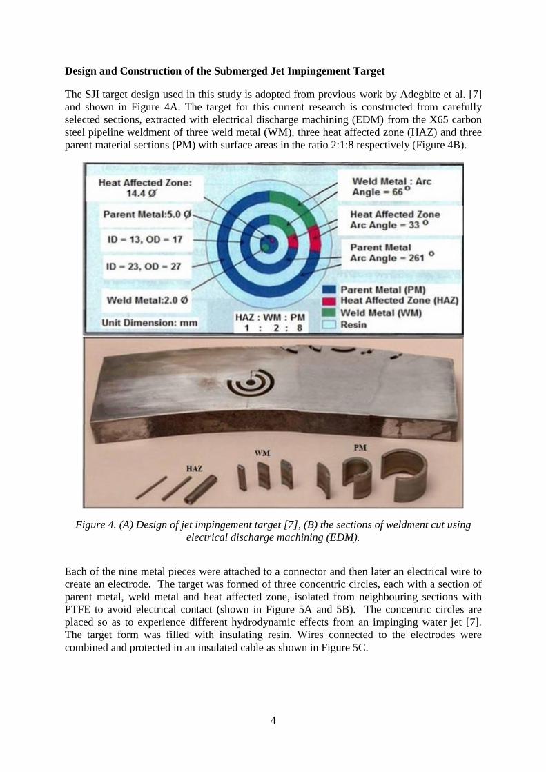
Design and Construction of the Submerged Jet Impingement Target
The SJI target design used in this study is adopted from previous work by Adegbite et al. [7]
and shown in Figure 4A. The target for this current research is constructed from carefully
selected sections, extracted with electrical discharge machining (EDM) from the X65 carbon
steel pipeline weldment of three weld metal (WM), three heat affected zone (HAZ) and three
parent material sections (PM) with surface areas in the ratio 2:1:8 respectively (Figure 4B).
Figure 4. (A) Design of jet impingement target [7], (B) the sections of weldment cut using
electrical discharge machining (EDM).
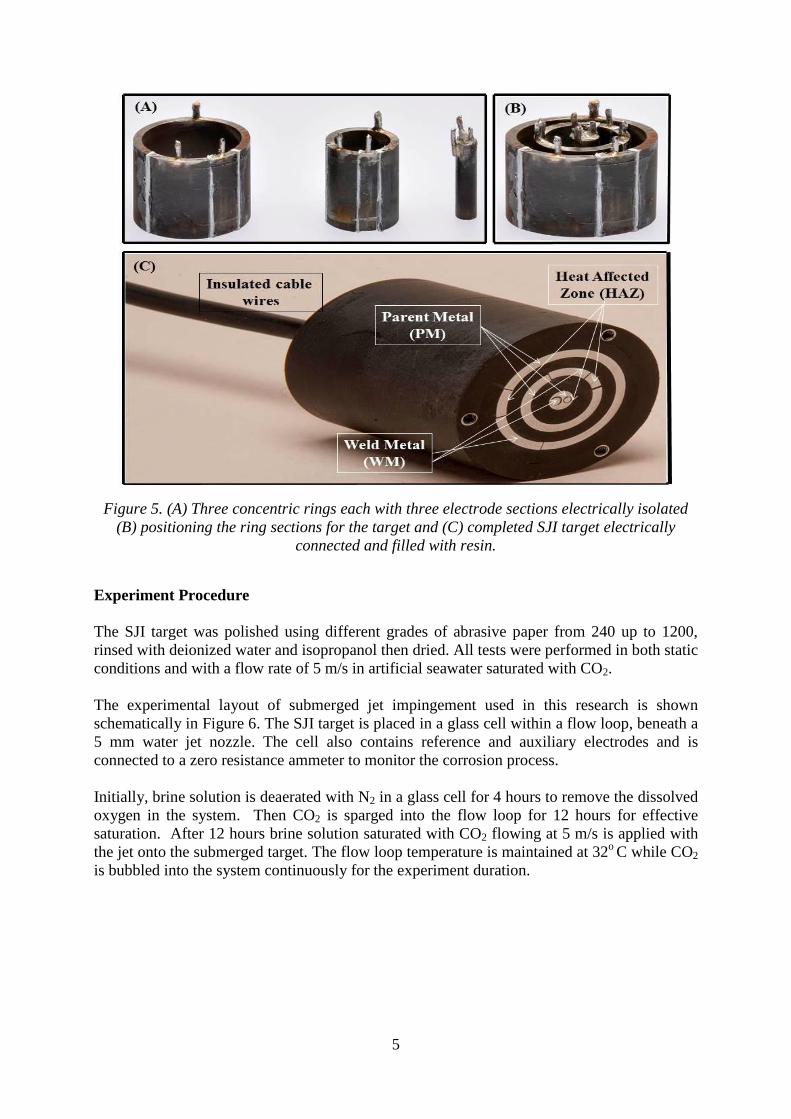
Each of the nine metal pieces were attached to a connector and then later an electrical wire to
create an electrode. The target was formed of three concentric circles, each with a section of
parent metal, weld metal and heat affected zone, isolated from neighbouring sections with
PTFE to avoid electrical contact (shown in Figure 5A and 5B). The concentric circles are
placed so as to experience different hydrodynamic effects from an impinging water jet [7].
The target form was filled with insulating resin. Wires connected to the electrodes were
combined and protected in an insulated cable as shown in Figure 5C.
5
Figure 5. (A) Three concentric rings each with three electrode sections electrically isolated
(B) positioning the ring sections for the target and (C) completed SJI target electrically
connected and filled with resin.
Experiment Procedure
The SJI target was polished using different grades of abrasive paper from 240 up to 1200,
rinsed with deionized water and isopropanol then dried. All tests were performed in both static
conditions and with a flow rate of 5 m/s in artificial seawater saturated with CO2.
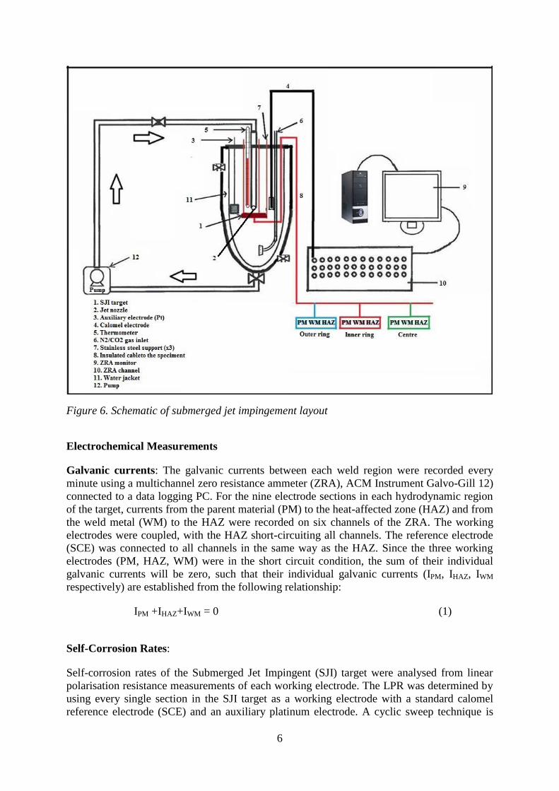
The experimental layout of submerged jet impingement used in this research is shown
schematically in Figure 6. The SJI target is placed in a glass cell within a flow loop, beneath a
5 mm water jet nozzle. The cell also contains reference and auxiliary electrodes and is
connected to a zero resistance ammeter to monitor the corrosion process.
Initially, brine solution is deaerated with N2 in a glass cell for 4 hours to remove the dissolved
oxygen in the system. Then CO2 is sparged into the flow loop for 12 hours for effective
saturation. After 12 hours brine solution saturated with CO2 flowing at 5 m/s is applied with
the jet onto the submerged target. The flow loop temperature is maintained at 32o C while CO2
is bubbled into the system continuously for the experiment duration.
6
Figure 6. Schematic of submerged jet impingement layout
Electrochemical Measurements
Galvanic currents: The galvanic currents between each weld region were recorded every
minute using a multichannel zero resistance ammeter (ZRA), ACM Instrument Galvo-Gill 12)
connected to a data logging PC. For the nine electrode sections in each hydrodynamic region
of the target, currents from the parent material (PM) to the heat-affected zone (HAZ) and from
the weld metal (WM) to the HAZ were recorded on six channels of the ZRA. The working
electrodes were coupled, with the HAZ short-circuiting all channels. The reference electrode
(SCE) was connected to all channels in the same way as the HAZ. Since the three working
electrodes (PM, HAZ, WM) were in the short circuit condition, the sum of their individual
galvanic currents will be zero, such that their individual galvanic currents (IPM, IHAZ, IWM
respectively) are established from the following relationship:
IPM +IHAZ+IWM = 0 (1)
Self-Corrosion Rates:
Self-corrosion rates of the Submerged Jet Impingent (SJI) target were analysed from linear
polarisation resistance measurements of each working electrode. The LPR was determined by
using every single section in the SJI target as a working electrode with a standard calomel
reference electrode (SCE) and an auxiliary platinum electrode. A cyclic sweep technique is
7
used to scan each uncoupled electrode from 10 mV (SCE) below the open circuit potential
(OCP) to 10 mV (SCE) above the OCP and back to the starting potential. Changes of current
during the process were recorded every second.
The resulting potential/current density plot exhibited a straight line where the gradient is
inversely related to the corrosion rate. This results in the polarisation resistance Rp, which is
related to the corrosion current using equation 2:
𝑅𝑝 = 𝛥𝐸/𝛥𝐼 = ß/(𝐼𝑐𝑜𝑟𝑟) (2)
Where:
Rp = polarisation resistance (Ωcm2)
Icorr = corrosion current (A/cm2)
ß = Stern-Geary constant related to the anodic (ba) and cathodic (bc) Tafel slopes
Electrochemical Impedance Spectroscopy (EIS)
Electrochemical impedance spectroscopy was used to complement the LPR measurements
and confirm the self-corrosion rates. The potential was scanned +/- 10mV of the open circuit
potential, as in the LPR measurements, at frequencies ranging from 20kHz to 0.05 Hz and the
corresponding currents were recorded and used to calculate the impedance of the corrosion
processes. In addition, EIS can be used to investigate the corrosion mechanism and the
influence of surface films result from either the corrosion process or action of the inhibitor.
3. Results and Discussion
Typical results are reported here for the corrosion measurements on the outer ring of the SJI
target at a flow rate of 5m/s and a temperature of 32 oC.
Galvanic Current Measurements
The results of the galvanic current measurements are given in Figure 7. During the initial
deaeration stage with nitrogen (a), the galvanic currents are small and slowly decrease. The
deaeration is monitored by recording the electrode potentials, which become more
electronegative as dissolved oxygen is removed. Figure 8 shows that the potentials of the
PM/HAZ and WM/HAZ couples are lowered to approximately -640mV(SCE) during this
period. The brine is considered to be well deaerated when the potential reaches -730mV(SCE)
so in these initial experiments there was still some dissolved oxygen present.
When CO2 is bubbled into the cell (b), there is a further active shift in the electrode potentials
to -754 mV(SCE) as the steel electrodes are attacked by the carbonic acid (Figure 8)
accompanied by an increase in the galvanic currents (Figure 7). At this stage, the PM is
slightly anodic to the other two weld regions (a positive current) and the WM and HAZ are
both cathodic (negative currents) and therefore partially protected from corrosion.
After flowing CO2 into the solution for 6h, the pump is started and the brine impinges on the
target electrodes at 5m/s (c). There is a large transient increase in the galvanic currents, which
quickly stabilises, leaving a reversal in the current direction on the WM. Whereas the WM
has been cathodic in static conditions, it now becomes anodic, providing corrosion protection
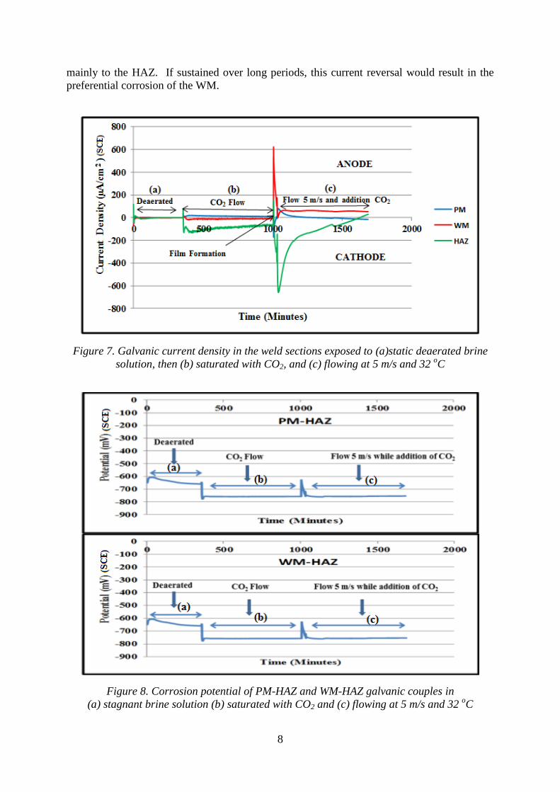
8
mainly to the HAZ. If sustained over long periods, this current reversal would result in the
preferential corrosion of the WM.
Figure 7. Galvanic current density in the weld sections exposed to (a)static deaerated brine
solution, then (b) saturated with CO2, and (c) flowing at 5 m/s and 32 oC
Figure 8. Corrosion potential of PM-HAZ and WM-HAZ galvanic couples in
(a) stagnant brine solution (b) saturated with CO2 and (c) flowing at 5 m/s and 32 oC
9
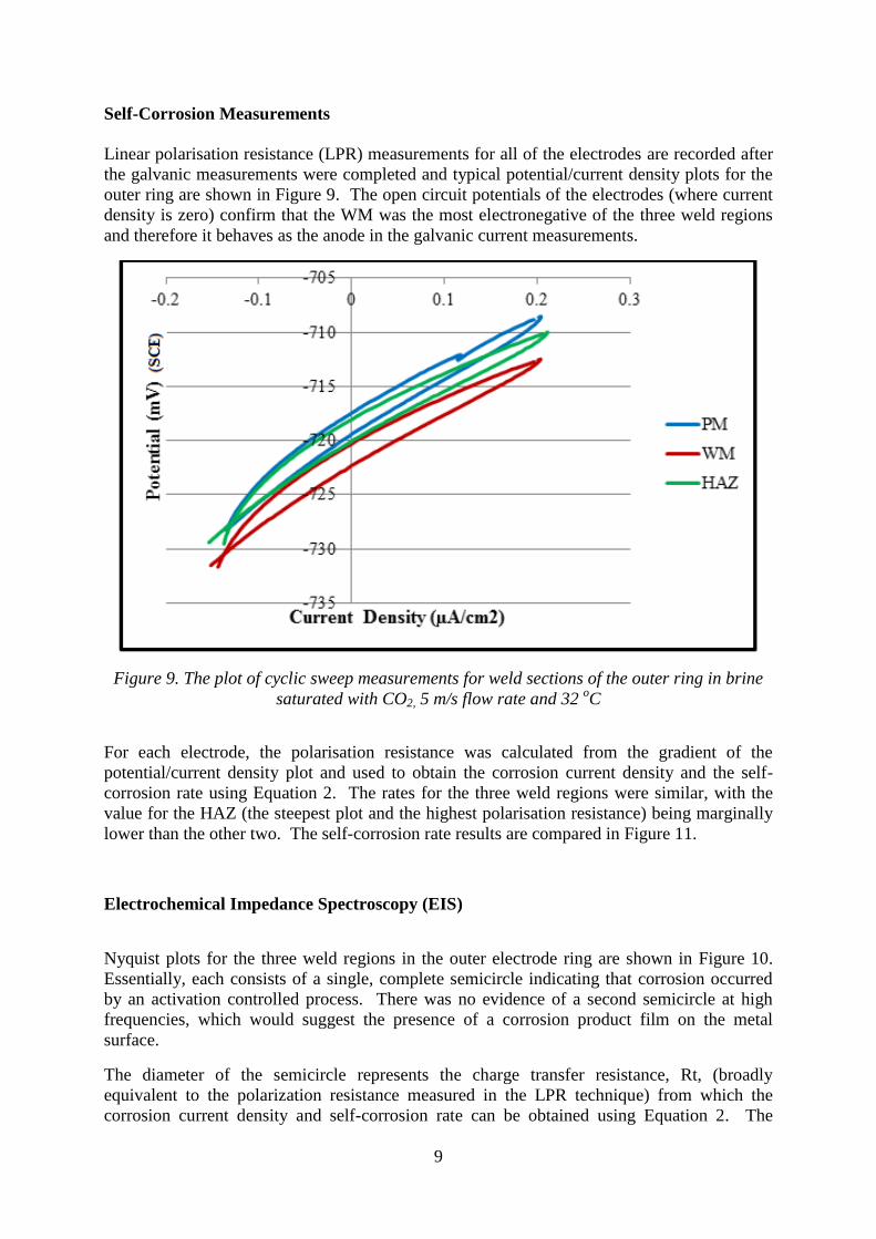
Self-Corrosion Measurements
Linear polarisation resistance (LPR) measurements for all of the electrodes are recorded after
the galvanic measurements were completed and typical potential/current density plots for the
outer ring are shown in Figure 9. The open circuit potentials of the electrodes (where current
density is zero) confirm that the WM was the most electronegative of the three weld regions
and therefore it behaves as the anode in the galvanic current measurements.
Figure 9. The plot of cyclic sweep measurements for weld sections of the outer ring in brine
saturated with CO2, 5 m/s flow rate and 32 oC
For each electrode, the polarisation resistance was calculated from the gradient of the
potential/current density plot and used to obtain the corrosion current density and the self-
corrosion rate using Equation 2. The rates for the three weld regions were similar, with the
value for the HAZ (the steepest plot and the highest polarisation resistance) being marginally
lower than the other two. The self-corrosion rate results are compared in Figure 11.
Electrochemical Impedance Spectroscopy (EIS)
Nyquist plots for the three weld regions in the outer electrode ring are shown in Figure 10.
Essentially, each consists of a single, complete semicircle indicating that corrosion occurred
by an activation controlled process. There was no evidence of a second semicircle at high
frequencies, which would suggest the presence of a corrosion product film on the metal
surface.
The diameter of the semicircle represents the charge transfer resistance, Rt, (broadly
equivalent to the polarization resistance measured in the LPR technique) from which the
corrosion current density and self-corrosion rate can be obtained using Equation 2. The
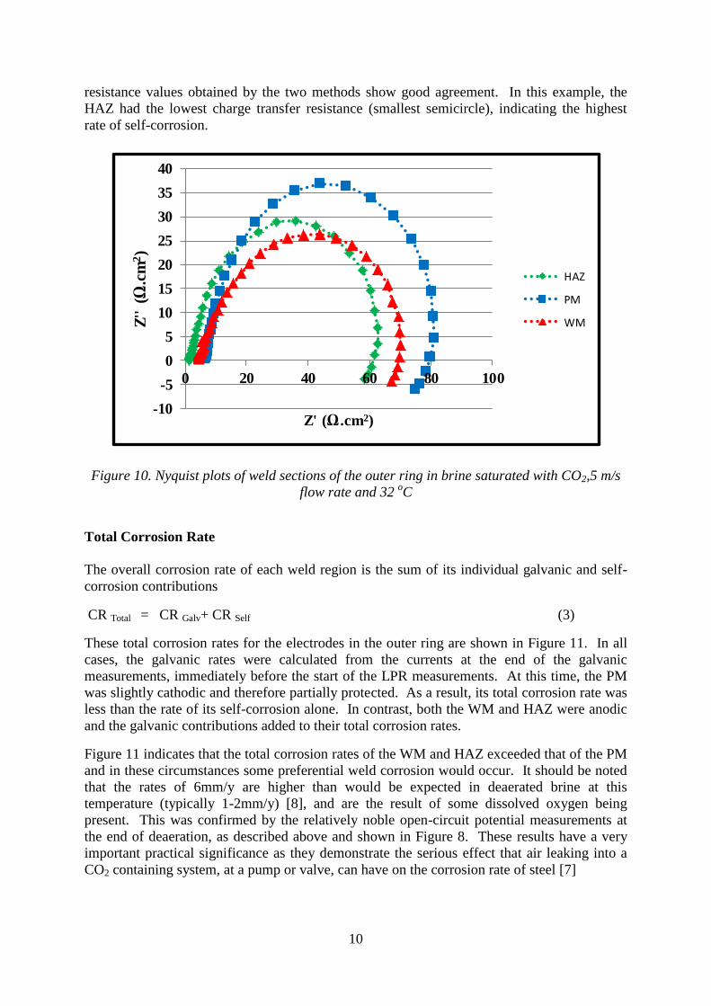
10
resistance values obtained by the two methods show good agreement. In this example, the
HAZ had the lowest charge transfer resistance (smallest semicircle), indicating the highest
rate of self-corrosion.
Figure 10. Nyquist plots of weld sections of the outer ring in brine saturated with CO2,5 m/s
flow rate and 32 oC
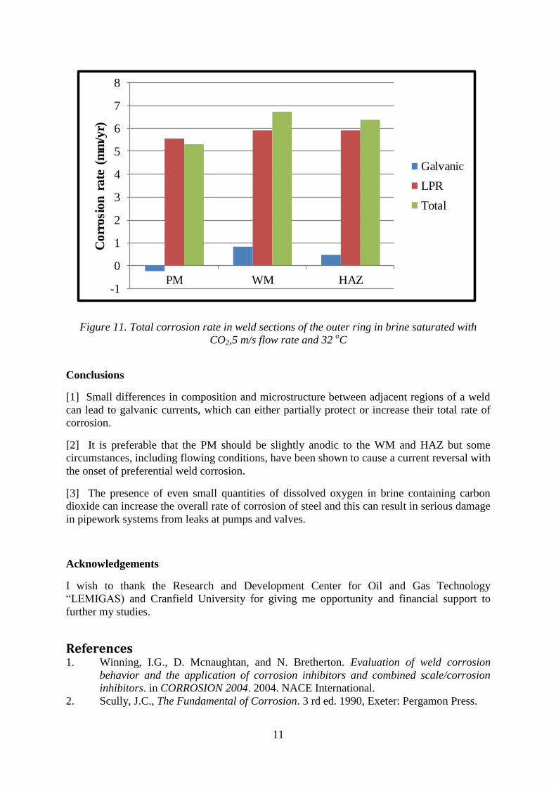
Total Corrosion Rate
The overall corrosion rate of each weld region is the sum of its individual galvanic and self-
corrosion contributions
CR Total = CR Galv+ CR Self (3)
These total corrosion rates for the electrodes in the outer ring are shown in Figure 11. In all
cases, the galvanic rates were calculated from the currents at the end of the galvanic
measurements, immediately before the start of the LPR measurements. At this time, the PM
was slightly cathodic and therefore partially protected. As a result, its total corrosion rate was
less than the rate of its self-corrosion alone. In contrast, both the WM and HAZ were anodic
and the galvanic contributions added to their total corrosion rates.
Figure 11 indicates that the total corrosion rates of the WM and HAZ exceeded that of the PM
and in these circumstances some preferential weld corrosion would occur. It should be noted
that the rates of 6mm/y are higher than would be expected in deaerated brine at this
temperature (typically 1-2mm/y) [8], and are the result of some dissolved oxygen being
present. This was confirmed by the relatively noble open-circuit potential measurements at
the end of deaeration, as described above and shown in Figure 8. These results have a very
important practical significance as they demonstrate the serious effect that air leaking into a
CO2 containing system, at a pump or valve, can have on the corrosion rate of steel [7]
-10
-5
0
5
10
15
20
25
30
35
40
0 20 40 60 80 100
Z'' (Ω.c
m2)
Z' (Ω.cm2)
HAZ
PM
WM
11
Figure 11. Total corrosion rate in weld sections of the outer ring in brine saturated with
CO2,5 m/s flow rate and 32 oC
Conclusions
[1] Small differences in composition and microstructure between adjacent regions of a weld
can lead to galvanic currents, which can either partially protect or increase their total rate of
corrosion.
[2] It is preferable that the PM should be slightly anodic to the WM and HAZ but some
circumstances, including flowing conditions, have been shown to cause a current reversal with
the onset of preferential weld corrosion.
[3] The presence of even small quantities of dissolved oxygen in brine containing carbon
dioxide can increase the overall rate of corrosion of steel and this can result in serious damage
in pipework systems from leaks at pumps and valves.
Acknowledgements
I wish to thank the Research and Development Center for Oil and Gas Technology
“LEMIGAS) and Cranfield University for giving me opportunity and financial support to
further my studies.
References 1. Winning, I.G., D. Mcnaughtan, and N. Bretherton. Evaluation of weld corrosion
behavior and the application of corrosion inhibitors and combined scale/corrosion
inhibitors. in CORROSION 2004. 2004. NACE International.
2. Scully, J.C., The Fundamental of Corrosion. 3 rd ed. 1990, Exeter: Pergamon Press.
-1
0
1
2
3
4
5
6
7
8
PM WM HAZ
Corr
osi
on
rate
(m
m/y
r)
Galvanic
LPR
Total
12
3. Mahajanam, S.P. and M.W. Joosten, Guidelines for Filler-Material Selection To
Minimize Preferential Weld Corrosion in Pipeline Steels. SPE Projects, Facilities &
Construction, 2011. 6(01): p. 5-12.
4. Obanijesu, E.O., et al., The influence of corrosion inhibitors on hydrate formation
temperature along the subsea natural gas pipelines. Journal of Petroleum Science and
Engineering, 2014. 120: p. 239-252.
5. Martinez, M., et al. Control of preferential weld corrosion of X65 pipeline steel in
flowing brines containing carbon dioxide. in CORROSION 2011. 2011. NACE
International.
6. Alawadhi, K., Inhibition of weld corrosion in flowing brines containing carbon
dioxide. 2009.
7. Adegbite, M., S. Impey, and M. Robinson. The Influence of Hydrodynamics on the
Preferential Weld Corrosion of X65 Linepipe Steel in Flowing Brine Containing
Carbon Dioxide. in CORROSION 2014. 2014. NACE International.
8. Allison, C. and M. Robinson. Assessment of Vented Flexible Liners For Corrosion
Protection of Pipelines. in CORROSION 2011. 2011. NACE International.


![ENVIRONMENTAL BEHAVIOR · 2018-04-14 · preferential weld corrosion [48] and pitting in sodium. bromide -[49]. Weld corrosion has also been related to the microstructure and to the](https://img.pdfslide.net/doc/110x75/5ea07528ca0c205f90219f8c/environmental-behavior-2018-04-14-preferential-weld-corrosion-48-and-pitting.jpg)