Embed Size (px)
Citation preview
16TH
INTERNATIONAL CONFERENCE ON COMPOSITE MATERIALS
1
Abstract
This study explores the effect of voids in the 1-6%
range on the flexural fatigue properties of
unidirectional carbon fibre reinforced epoxy
polymer composites (CFRP) as used by the wind
turbine industry. Samples with different void content
were successfully obtained by varying the
manufacturing process. Void content were acquired
from three-point bending test samples and
correlated with the three-point bending test results.
There is a general trend of increasing fatigue
strength with decreasing void content. Acoustic
emission results show that the major failure is due to
fibre breakage. Observation of damage using x-ray
computed tomography shows failures that consist of
crack under the roller and a separate delamination
starting from voids.
1 Introduction
The presence of defects can severely degrade
the mechanical properties of composite materials
and not surprisingly their effects have been
extensively researched in recent years [1]. Voids are
regarded as being particularly significant because
they are inherent in any manufacturing process.
Acceptable void levels vary from less than 1% in
aerospace applications to in excess of 5% in
automotive and marine applications.
There is a general agreement that the tensile
(fibre dominated properties) are not significantly
influenced by voids but it is well established that the
matrix dominated properties such as compressive
and flexural are significantly affected [2]. Ideally
composites are not exposed to these loading regimes
but in the case of wind turbines both compression
and flexure are real issues.
Less attention has been given to the
development of damage in composite laminates
loaded in flexure due to the presence of both tensile
and compressive stress in the material making it
more difficult to interpret. In particular, studies on
damage development for CFRP containing voids
loaded in flexure are still not well explored.
The aims and objectives of this research are to
develop an understanding of effect of voids on the
fatigue behaviour of unidirectional carbon/epoxy
composites.
2. Background
For CFRP, the tensile fatigue resistance at
stresses below 80% of the static strength is excellent.
However, in flexural fatigue, damage occurs at
smaller loads and after a fewer cycles [3]. Flexural
fatigue loading was reported to have a more serious
effect on the fatigue resistance of the composite
compared with uniaxial loading because it places a
more severe stress on the matrix of the composite.
Several researchers have described how
unidirectional CFRP failed from flexural fatigue
damage. Croman [4] observed that fatigue failure
initiation was by compression failure in the vicinity
of the loading nose. This damage increased in length
toward the mid-plane. With increasing cycles,
delaminations to the right and left appeared and
grew until the specimen finally failed into two
pieces via tensile breaking of the fibres on the tensile
side of the specimens. Failure started at compression
side due to the downward thrust of the point loading
that subjected the uppermost fibres to longitudinal
compression and lateral thrust. The fibres buckled
and failed at the same time resulting in the sudden
appearance of compression side cracks.
THE EFFECT OF VOIDS ON THE FLEXURAL FATIGUE PERFORMANCE OF UNIDIRECTIONAL CARBON FIBRE
COMPOSITES
Mohamed A. Suhot*, Alan R. Chambers*
*School of Engineering Sciences, University of Southampton, Highfield, Southampton. SO17
1BJ, UK
Keywords: voids, flexural fatigue, carbon fibre, acoustic emission, x-ray ctscan
MOHAMED A. SUHOT, Chambers
2
There are several reasons for the decrease of
strength due to the presence of voids, including
voids acting as a break in fibre-matrix adhesion [2],
shearing due to the presence of voids in fibre/matrix
interface and resin [5], voids reducing the cross-
sectional area and acting as failure initiator [6] and a
variation of a notched strength criterion [7]. In a
review of bending tests, Mullin and Knoell [8]
discussed the effects of specimen flaw such as voids
on flexural strength. The maximum flexural stress
location is at the outermost layers of the laminate
and the maximum shear stress is at the vertical plane
under the loading roll. Therefore a single flaw at
these locations could diminish the overall flexural
strength.
3. Experimental procedures
3.1 Materials
Both SPRINT* and prepreg were used to
produce four ply unidirectional carbon/epoxy
composites. SPRINT materials consist of a layer of
fibre reinforcement on each side of a precast,
precatalysed resin film, with a light tack film on one
face. SPRINT is different from the usual prepregs, in
the sense that its fibres stay dry and unimpregnated
by the resin until the curing process [9]. For the
prepreg materials, the base material is a
carbon/epoxy prepreg by SP Systems, made of
500g/m2 of unidirectional carbon fibre. All the
laminates were manufactured by vacuum bagging
process.
The primary objective of this work is to
investigate the effect of voids on the flexural fatigue
performance. In order to achieve a range of voids,
SPRINT laminates were produced using vacuum
pressures of 70%, 80%, 90% and 100% of the
manufacturer’s recommended vacuum pressure
(70% vacuum is an inferior to 100% vacuum). For
the prepreg laminates, the difference in quality was
achieved by debaulking and non-debaulking.
3.2 Image analysis
To determine the quality of the laminate, void
contents were measured using computerized image
analysis. Void content measurements were made on
previously tested flexural fatigue specimens to gain
a void content representative of the material in the
failure zone. Thus image analysis was conducted 30
* SP Systems trademark
mm away from the failure point along the axis
perpendicular to the direction of the fibre
orientation. Next the statistical average of void
percentages in the processed images was taken as
equal to the void volume percentage. This method is
thus far considered among the most precise for
measuring the void content [10].
Carefully prepared specimens were placed
under an optical Olympus BH-2 microscope
interfaced to a PC based computer using a DVC
digital video camera module. Voids in the image in
the optical microscope analysis were separated from
the background (resin and fibres) by adjusting the
light intensity of the microscope until only the voids
were highlighted. The images were fed to the
computer using XCap image analysis software.
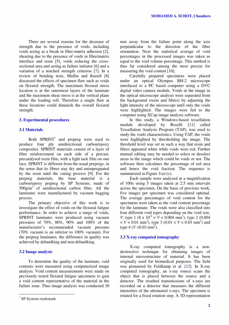
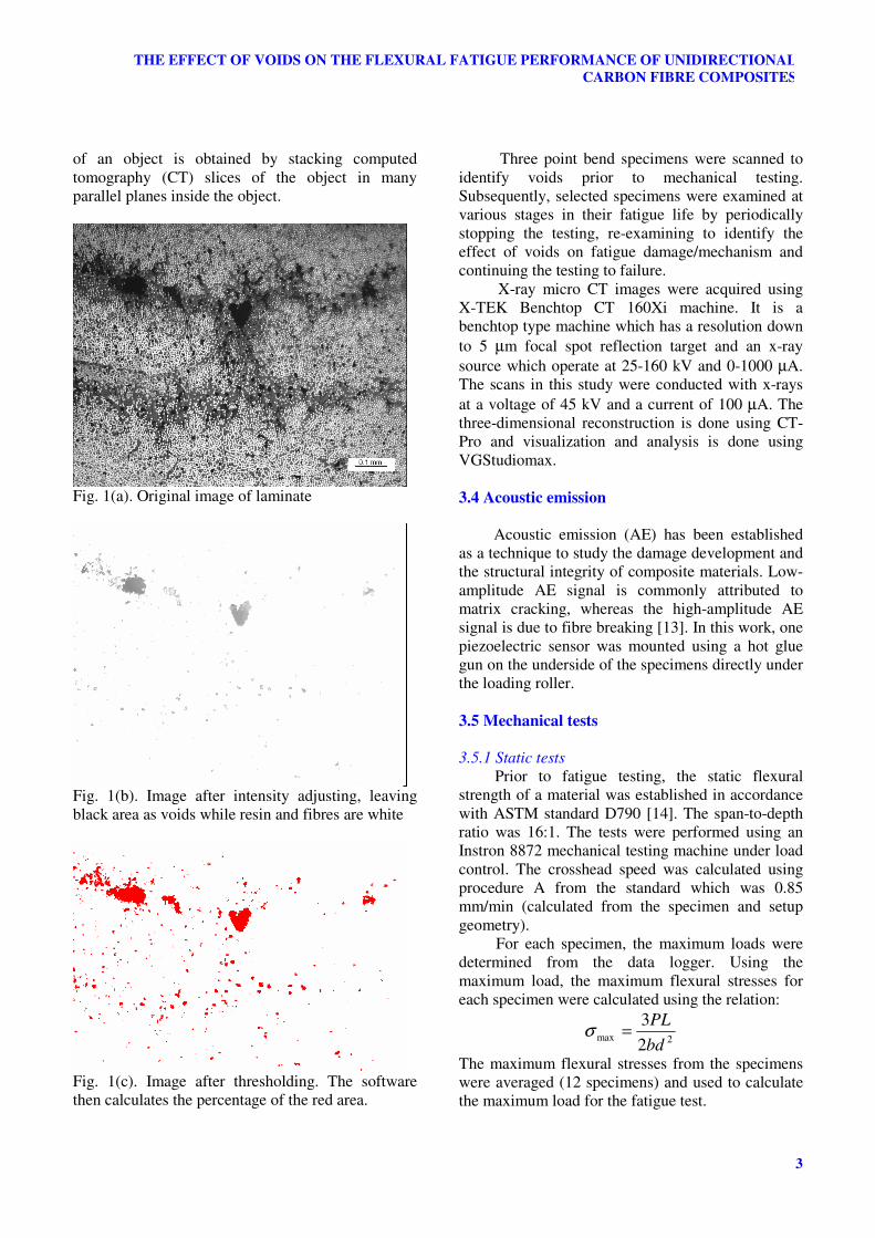
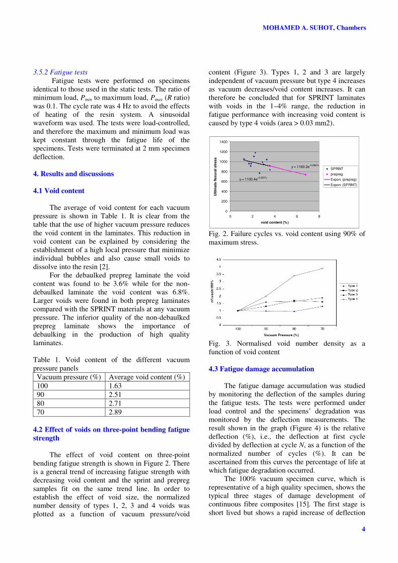
In this study, a Windows-based tessellation
module developed by Boselli [11] called
Tessellation Analysis Program (TAP), was used to
study the voids characteristics. Using TAP, the voids
were highlighted by thresholding the image. The
threshold level was set in such a way that resin and
fibres appeared white while voids were red. Further
manual editing may be needed to select or deselect
areas in the image which could be voids or not. The
software then calculates the percentage of red area
and hence the void fraction. The sequence is
summarized in Figure 1(a)-(c).
Each sample were analysed at a magnification
of 100x using 5 images taken at 2.5 mm intervals
across the specimen. On the basis of previous work,
five images per specimen was considered optimal.
The average percentages of void content for the
specimens were taken as the void content percentage
for the laminate. The voids were also classified into
four different void types depending on the void size,
V: type 1 (8 x 10⁻⁶
< V < 0.004 mm2), type 2 (0.004
< V < 0.01 mm2), type 3 (0.01 < V < 0.03 mm
2) and
type 4 (V >0.03 mm2).
3.3 X-ray computed tomography
X-ray computed tomography is a non-
destructive technique for obtaining images of
internal microstructure of material. It has been
originally used for biomedical purposes. The field
was pioneered by Feldkamp et al. [12]. In X-ray
computed tomography, an x-ray source scans the
object that is placed between the source and a
detector. The resulted transmissions of x-rays are
recorded on a detector that measures the different
intensities of the attenuated x-rays. The specimen is
rotated for a fixed rotation step. A 3D representation
3
THE EFFECT OF VOIDS ON THE FLEXURAL FATIGUE PERFORMANCE OF UNIDIRECTIONAL
CARBON FIBRE COMPOSITES
of an object is obtained by stacking computed
tomography (CT) slices of the object in many
parallel planes inside the object.
Fig. 1(a). Original image of laminate
Fig. 1(b). Image after intensity adjusting, leaving
black area as voids while resin and fibres are white
Fig. 1(c). Image after thresholding. The software
then calculates the percentage of the red area.
Three point bend specimens were scanned to
identify voids prior to mechanical testing.
Subsequently, selected specimens were examined at
various stages in their fatigue life by periodically
stopping the testing, re-examining to identify the
effect of voids on fatigue damage/mechanism and
continuing the testing to failure.
X-ray micro CT images were acquired using
X-TEK Benchtop CT 160Xi machine. It is a
benchtop type machine which has a resolution down
to 5 µm focal spot reflection target and an x-ray
source which operate at 25-160 kV and 0-1000 µA.
The scans in this study were conducted with x-rays
at a voltage of 45 kV and a current of 100 µA. The
three-dimensional reconstruction is done using CT-
Pro and visualization and analysis is done using
VGStudiomax.
3.4 Acoustic emission
Acoustic emission (AE) has been established
as a technique to study the damage development and
the structural integrity of composite materials. Low-
amplitude AE signal is commonly attributed to
matrix cracking, whereas the high-amplitude AE
signal is due to fibre breaking [13]. In this work, one
piezoelectric sensor was mounted using a hot glue
gun on the underside of the specimens directly under
the loading roller.
3.5 Mechanical tests
3.5.1 Static tests
Prior to fatigue testing, the static flexural
strength of a material was established in accordance
with ASTM standard D790 [14]. The span-to-depth
ratio was 16:1. The tests were performed using an
Instron 8872 mechanical testing machine under load
control. The crosshead speed was calculated using
procedure A from the standard which was 0.85
mm/min (calculated from the specimen and setup
geometry).
For each specimen, the maximum loads were
determined from the data logger. Using the
maximum load, the maximum flexural stresses for
each specimen were calculated using the relation:
2max2
3
bd
PL=σ
The maximum flexural stresses from the specimens
were averaged (12 specimens) and used to calculate
the maximum load for the fatigue test.
MOHAMED A. SUHOT, Chambers
4
3.5.2 Fatigue tests
Fatigue tests were performed on specimens
identical to those used in the static tests. The ratio of
minimum load, Pmin to maximum load, Pmax (R ratio)
was 0.1. The cycle rate was 4 Hz to avoid the effects
of heating of the resin system. A sinusoidal
waveform was used. The tests were load-controlled,
and therefore the maximum and minimum load was
kept constant through the fatigue life of the
specimens. Tests were terminated at 2 mm specimen
deflection.
4. Results and discussions
4.1 Void content
The average of void content for each vacuum
pressure is shown in Table 1. It is clear from the
table that the use of higher vacuum pressure reduces
the void content in the laminates. This reduction in
void content can be explained by considering the
establishment of a high local pressure that minimize
individual bubbles and also cause small voids to
dissolve into the resin [2].
For the debaulked prepreg laminate the void
content was found to be 3.6% while for the non-
debaulked laminate the void content was 6.8%.
Larger voids were found in both prepreg laminates
compared with the SPRINT materials at any vacuum
pressure. The inferior quality of the non-debaulked
prepreg laminate shows the importance of
debaulking in the production of high quality
laminates.
Table 1. Void content of the different vacuum
pressure panels
Vacuum pressure (%) Average void content (%)
100 1.63
90 2.51
80 2.71
70 2.89
4.2 Effect of voids on three-point bending fatigue
strength
The effect of void content on three-point
bending fatigue strength is shown in Figure 2. There
is a general trend of increasing fatigue strength with
decreasing void content and the sprint and prepreg
samples fit on the same trend line. In order to
establish the effect of void size, the normalized
number density of types 1, 2, 3 and 4 voids was
plotted as a function of vacuum pressure/void
content (Figure 3). Types 1, 2 and 3 are largely
independent of vacuum pressure but type 4 increases
as vacuum decreases/void content increases. It can
therefore be concluded that for SPRINT laminates
with voids in the 1–4% range, the reduction in
fatigue performance with increasing void content is
caused by type 4 voids (area > 0.03 mm2).
y = 1160.3e-0.0667x
y = 1100.4e-0.0527x
0
200
400
600
800
1000
1200
1400
0 2 4 6 8
void content (%)
Ult
ima
te f
lex
ura
l s
tre
ss
SPRINT
prepreg
Expon. (prepreg)
Expon. (SPRINT)
Fig. 2. Failure cycles vs. void content using 90% of
maximum stress.
Fig. 3. Normalised void number density as a
function of void content
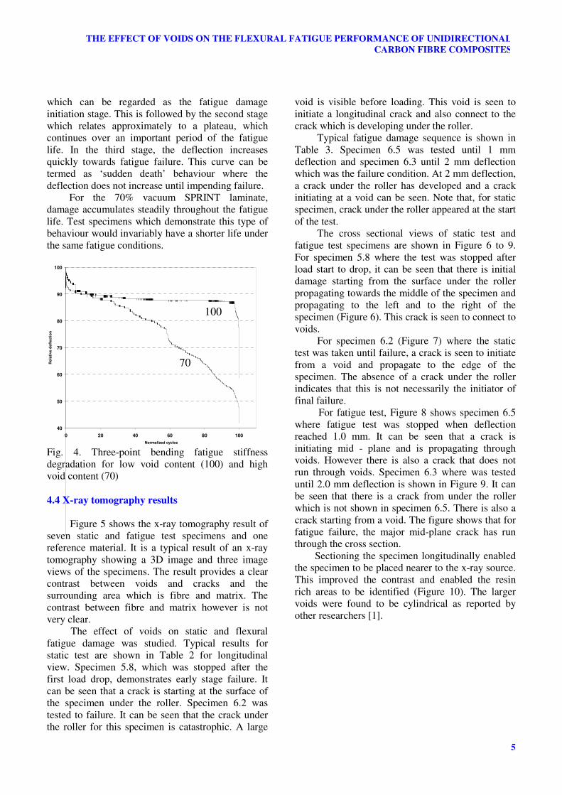
4.3 Fatigue damage accumulation
The fatigue damage accumulation was studied
by monitoring the deflection of the samples during
the fatigue tests. The tests were performed under
load control and the specimens’ degradation was
monitored by the deflection measurements. The
result shown in the graph (Figure 4) is the relative
deflection (%), i.e., the deflection at first cycle
divided by deflection at cycle N, as a function of the
normalized number of cycles (%). It can be
ascertained from this curves the percentage of life at
which fatigue degradation occurred.
The 100% vacuum specimen curve, which is
representative of a high quality specimen, shows the
typical three stages of damage development of
continuous fibre composites [15]. The first stage is
short lived but shows a rapid increase of deflection
5
THE EFFECT OF VOIDS ON THE FLEXURAL FATIGUE PERFORMANCE OF UNIDIRECTIONAL
CARBON FIBRE COMPOSITES
which can be regarded as the fatigue damage
initiation stage. This is followed by the second stage
which relates approximately to a plateau, which
continues over an important period of the fatigue
life. In the third stage, the deflection increases
quickly towards fatigue failure. This curve can be
termed as ‘sudden death’ behaviour where the
deflection does not increase until impending failure.
For the 70% vacuum SPRINT laminate,
damage accumulates steadily throughout the fatigue
life. Test specimens which demonstrate this type of
behaviour would invariably have a shorter life under
the same fatigue conditions.
40
50
60
70
80
90
100
0 20 40 60 80 100
Normalized cycles
Re
lati
ve d
efl
ecti
on
Fig. 4. Three-point bending fatigue stiffness
degradation for low void content (100) and high
void content (70)
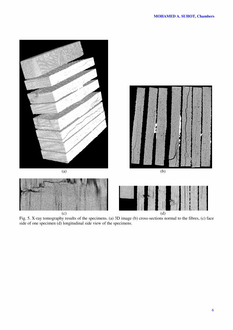
4.4 X-ray tomography results
Figure 5 shows the x-ray tomography result of
seven static and fatigue test specimens and one
reference material. It is a typical result of an x-ray
tomography showing a 3D image and three image
views of the specimens. The result provides a clear
contrast between voids and cracks and the
surrounding area which is fibre and matrix. The
contrast between fibre and matrix however is not
very clear.
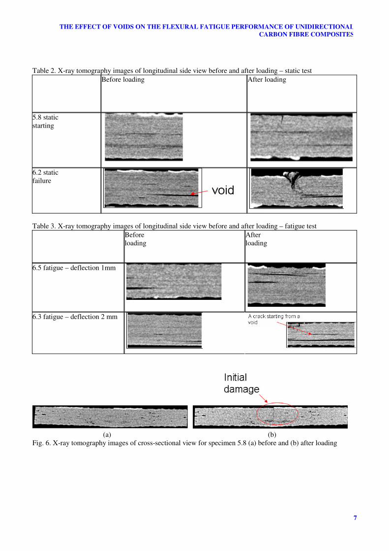
The effect of voids on static and flexural
fatigue damage was studied. Typical results for
static test are shown in Table 2 for longitudinal
view. Specimen 5.8, which was stopped after the
first load drop, demonstrates early stage failure. It
can be seen that a crack is starting at the surface of
the specimen under the roller. Specimen 6.2 was
tested to failure. It can be seen that the crack under
the roller for this specimen is catastrophic. A large
void is visible before loading. This void is seen to
initiate a longitudinal crack and also connect to the
crack which is developing under the roller.
Typical fatigue damage sequence is shown in
Table 3. Specimen 6.5 was tested until 1 mm
deflection and specimen 6.3 until 2 mm deflection
which was the failure condition. At 2 mm deflection,
a crack under the roller has developed and a crack
initiating at a void can be seen. Note that, for static
specimen, crack under the roller appeared at the start
of the test.
The cross sectional views of static test and
fatigue test specimens are shown in Figure 6 to 9.
For specimen 5.8 where the test was stopped after
load start to drop, it can be seen that there is initial
damage starting from the surface under the roller
propagating towards the middle of the specimen and
propagating to the left and to the right of the
specimen (Figure 6). This crack is seen to connect to
voids.
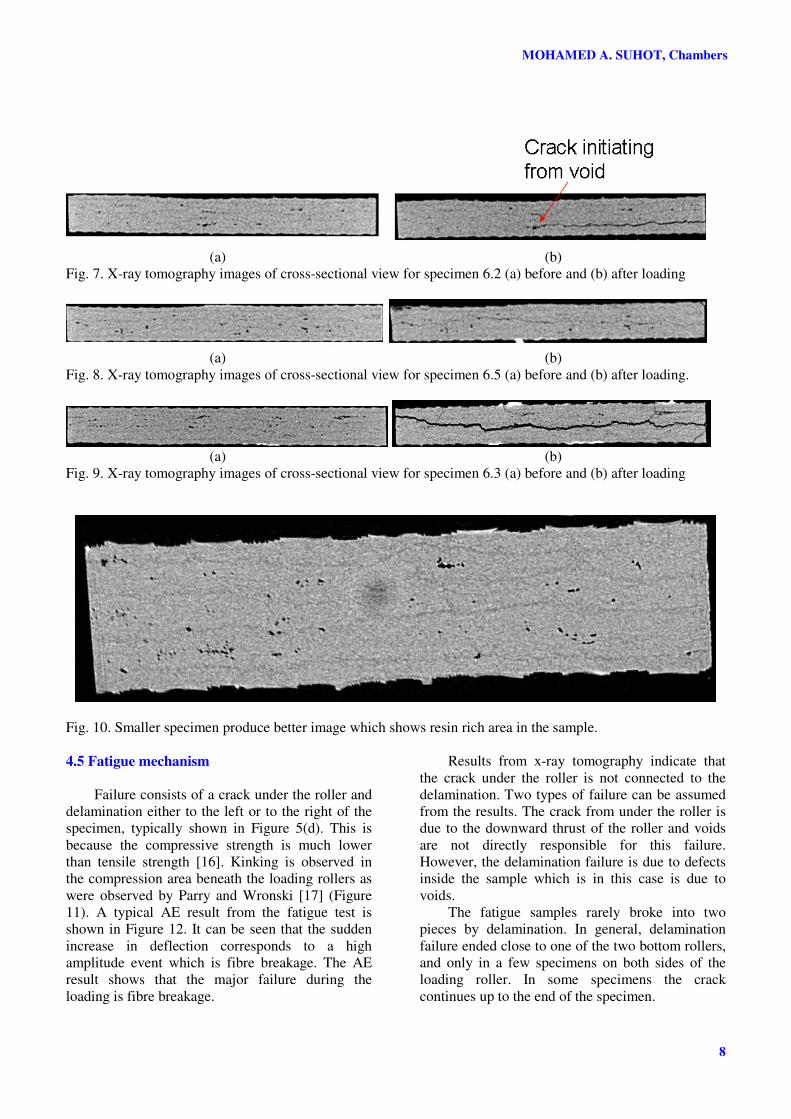
For specimen 6.2 (Figure 7) where the static
test was taken until failure, a crack is seen to initiate
from a void and propagate to the edge of the
specimen. The absence of a crack under the roller
indicates that this is not necessarily the initiator of
final failure.
For fatigue test, Figure 8 shows specimen 6.5
where fatigue test was stopped when deflection
reached 1.0 mm. It can be seen that a crack is
initiating mid - plane and is propagating through
voids. However there is also a crack that does not
run through voids. Specimen 6.3 where was tested
until 2.0 mm deflection is shown in Figure 9. It can
be seen that there is a crack from under the roller
which is not shown in specimen 6.5. There is also a
crack starting from a void. The figure shows that for
fatigue failure, the major mid-plane crack has run
through the cross section.
Sectioning the specimen longitudinally enabled
the specimen to be placed nearer to the x-ray source.
This improved the contrast and enabled the resin
rich areas to be identified (Figure 10). The larger
voids were found to be cylindrical as reported by
other researchers [1].
100
70
MOHAMED A. SUHOT, Chambers
6
(a) (b)
(c) (d)
Fig. 5. X-ray tomography results of the specimens. (a) 3D image (b) cross-sections normal to the fibres, (c) face
side of one specimen (d) longitudinal side view of the specimens.
7
THE EFFECT OF VOIDS ON THE FLEXURAL FATIGUE PERFORMANCE OF UNIDIRECTIONAL
CARBON FIBRE COMPOSITES
Table 2. X-ray tomography images of longitudinal side view before and after loading – static test
Before loading After loading
5.8 static
starting
6.2 static
failure
Table 3. X-ray tomography images of longitudinal side view before and after loading – fatigue test
Before
loading
After
loading
6.5 fatigue – deflection 1mm
6.3 fatigue – deflection 2 mm
(a) (b)
Fig. 6. X-ray tomography images of cross-sectional view for specimen 5.8 (a) before and (b) after loading
MOHAMED A. SUHOT, Chambers
8
(a) (b)
Fig. 7. X-ray tomography images of cross-sectional view for specimen 6.2 (a) before and (b) after loading
(a) (b)
Fig. 8. X-ray tomography images of cross-sectional view for specimen 6.5 (a) before and (b) after loading.
(a) (b)
Fig. 9. X-ray tomography images of cross-sectional view for specimen 6.3 (a) before and (b) after loading
Fig. 10. Smaller specimen produce better image which shows resin rich area in the sample.
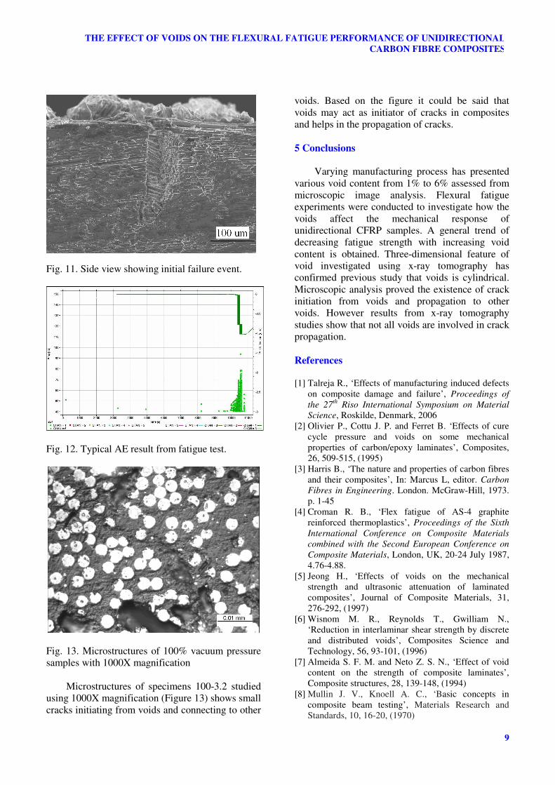
4.5 Fatigue mechanism
Failure consists of a crack under the roller and
delamination either to the left or to the right of the
specimen, typically shown in Figure 5(d). This is
because the compressive strength is much lower
than tensile strength [16]. Kinking is observed in
the compression area beneath the loading rollers as
were observed by Parry and Wronski [17] (Figure
11). A typical AE result from the fatigue test is
shown in Figure 12. It can be seen that the sudden
increase in deflection corresponds to a high
amplitude event which is fibre breakage. The AE
result shows that the major failure during the
loading is fibre breakage.
Results from x-ray tomography indicate that
the crack under the roller is not connected to the
delamination. Two types of failure can be assumed
from the results. The crack from under the roller is
due to the downward thrust of the roller and voids
are not directly responsible for this failure.
However, the delamination failure is due to defects
inside the sample which is in this case is due to
voids.
The fatigue samples rarely broke into two
pieces by delamination. In general, delamination
failure ended close to one of the two bottom rollers,
and only in a few specimens on both sides of the
loading roller. In some specimens the crack
continues up to the end of the specimen.
9
THE EFFECT OF VOIDS ON THE FLEXURAL FATIGUE PERFORMANCE OF UNIDIRECTIONAL
CARBON FIBRE COMPOSITES
Fig. 11. Side view showing initial failure event.
Fig. 12. Typical AE result from fatigue test.
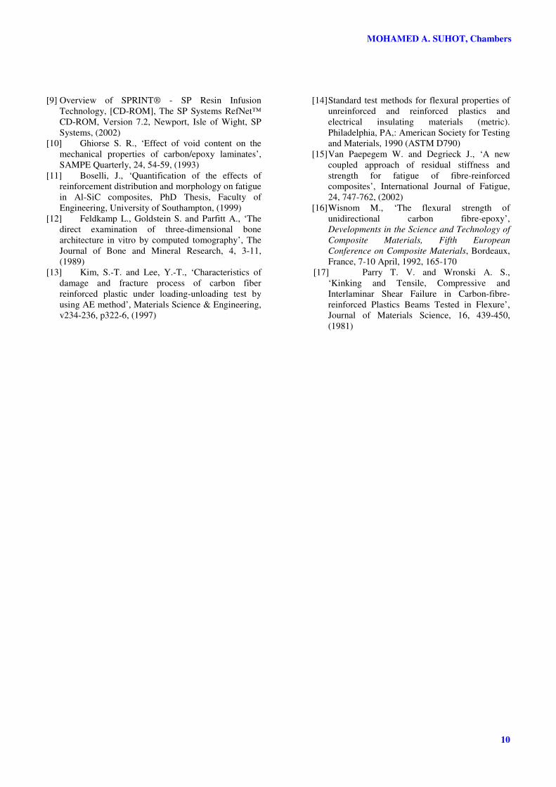
Fig. 13. Microstructures of 100% vacuum pressure
samples with 1000X magnification
Microstructures of specimens 100-3.2 studied
using 1000X magnification (Figure 13) shows small
cracks initiating from voids and connecting to other
voids. Based on the figure it could be said that
voids may act as initiator of cracks in composites
and helps in the propagation of cracks.
5 Conclusions
Varying manufacturing process has presented
various void content from 1% to 6% assessed from
microscopic image analysis. Flexural fatigue
experiments were conducted to investigate how the
voids affect the mechanical response of
unidirectional CFRP samples. A general trend of
decreasing fatigue strength with increasing void
content is obtained. Three-dimensional feature of
void investigated using x-ray tomography has
confirmed previous study that voids is cylindrical.
Microscopic analysis proved the existence of crack
initiation from voids and propagation to other
voids. However results from x-ray tomography
studies show that not all voids are involved in crack
propagation.
References
[1] Talreja R., ‘Effects of manufacturing induced defects
on composite damage and failure’, Proceedings of
the 27th
Riso International Symposium on Material
Science, Roskilde, Denmark, 2006
[2] Olivier P., Cottu J. P. and Ferret B. ‘Effects of cure
cycle pressure and voids on some mechanical
properties of carbon/epoxy laminates’, Composites,
26, 509-515, (1995)
[3] Harris B., ‘The nature and properties of carbon fibres
and their composites’, In: Marcus L, editor. Carbon
Fibres in Engineering. London. McGraw-Hill, 1973.
p. 1-45
[4] Croman R. B., ‘Flex fatigue of AS-4 graphite
reinforced thermoplastics’, Proceedings of the Sixth
International Conference on Composite Materials
combined with the Second European Conference on
Composite Materials, London, UK, 20-24 July 1987,
4.76-4.88.
[5] Jeong H., ‘Effects of voids on the mechanical
strength and ultrasonic attenuation of laminated
composites’, Journal of Composite Materials, 31,
276-292, (1997)
[6] Wisnom M. R., Reynolds T., Gwilliam N.,
‘Reduction in interlaminar shear strength by discrete
and distributed voids’, Composites Science and
Technology, 56, 93-101, (1996)
[7] Almeida S. F. M. and Neto Z. S. N., ‘Effect of void
content on the strength of composite laminates’,
Composite structures, 28, 139-148, (1994)
[8] Mullin J. V., Knoell A. C., ‘Basic concepts in
composite beam testing’, Materials Research and
Standards, 10, 16-20, (1970)
MOHAMED A. SUHOT, Chambers
10
[9] Overview of SPRINT® - SP Resin Infusion
Technology, [CD-ROM], The SP Systems RefNet™
CD-ROM, Version 7.2, Newport, Isle of Wight, SP
Systems, (2002)
[10] Ghiorse S. R., ‘Effect of void content on the
mechanical properties of carbon/epoxy laminates’,
SAMPE Quarterly, 24, 54-59, (1993)
[11] Boselli, J., ‘Quantification of the effects of
reinforcement distribution and morphology on fatigue
in Al-SiC composites, PhD Thesis, Faculty of
Engineering, University of Southampton, (1999)
[12] Feldkamp L., Goldstein S. and Parfitt A., ‘The
direct examination of three-dimensional bone
architecture in vitro by computed tomography’, The
Journal of Bone and Mineral Research, 4, 3-11,
(1989)
[13] Kim, S.-T. and Lee, Y.-T., ‘Characteristics of
damage and fracture process of carbon fiber
reinforced plastic under loading-unloading test by
using AE method’, Materials Science & Engineering,
v234-236, p322-6, (1997)
[14] Standard test methods for flexural properties of
unreinforced and reinforced plastics and
electrical insulating materials (metric).
Philadelphia, PA,: American Society for Testing
and Materials, 1990 (ASTM D790)
[15] Van Paepegem W. and Degrieck J., ‘A new
coupled approach of residual stiffness and
strength for fatigue of fibre-reinforced
composites’, International Journal of Fatigue,
24, 747-762, (2002)
[16] Wisnom M., ‘The flexural strength of
unidirectional carbon fibre-epoxy’,
Developments in the Science and Technology of
Composite Materials, Fifth European
Conference on Composite Materials, Bordeaux,
France, 7-10 April, 1992, 165-170
[17] Parry T. V. and Wronski A. S.,
‘Kinking and Tensile, Compressive and
Interlaminar Shear Failure in Carbon-fibre-
reinforced Plastics Beams Tested in Flexure’,
Journal of Materials Science, 16, 439-450,
(1981)